EP2952298A2 - Robot module - Google Patents
Robot moduleDownload PDFInfo
- Publication number
- EP2952298A2 EP2952298A2EP15159031.2AEP15159031AEP2952298A2EP 2952298 A2EP2952298 A2EP 2952298A2EP 15159031 AEP15159031 AEP 15159031AEP 2952298 A2EP2952298 A2EP 2952298A2
- Authority
- EP
- European Patent Office
- Prior art keywords
- module
- robot
- feed
- workpieces
- container
- Prior art date
- Legal status (The legal status is an assumption and is not a legal conclusion. Google has not performed a legal analysis and makes no representation as to the accuracy of the status listed.)
- Granted
Links
Images


Classifications
- B—PERFORMING OPERATIONS; TRANSPORTING
- B25—HAND TOOLS; PORTABLE POWER-DRIVEN TOOLS; MANIPULATORS
- B25J—MANIPULATORS; CHAMBERS PROVIDED WITH MANIPULATION DEVICES
- B25J9/00—Programme-controlled manipulators
- B25J9/16—Programme controls
- B25J9/1679—Programme controls characterised by the tasks executed
- B—PERFORMING OPERATIONS; TRANSPORTING
- B25—HAND TOOLS; PORTABLE POWER-DRIVEN TOOLS; MANIPULATORS
- B25J—MANIPULATORS; CHAMBERS PROVIDED WITH MANIPULATION DEVICES
- B25J9/00—Programme-controlled manipulators
- B25J9/0084—Programme-controlled manipulators comprising a plurality of manipulators
- B—PERFORMING OPERATIONS; TRANSPORTING
- B25—HAND TOOLS; PORTABLE POWER-DRIVEN TOOLS; MANIPULATORS
- B25J—MANIPULATORS; CHAMBERS PROVIDED WITH MANIPULATION DEVICES
- B25J21/00—Chambers provided with manipulation devices
- B—PERFORMING OPERATIONS; TRANSPORTING
- B25—HAND TOOLS; PORTABLE POWER-DRIVEN TOOLS; MANIPULATORS
- B25J—MANIPULATORS; CHAMBERS PROVIDED WITH MANIPULATION DEVICES
- B25J3/00—Manipulators of leader-follower type, i.e. both controlling unit and controlled unit perform corresponding spatial movements
- B—PERFORMING OPERATIONS; TRANSPORTING
- B25—HAND TOOLS; PORTABLE POWER-DRIVEN TOOLS; MANIPULATORS
- B25J—MANIPULATORS; CHAMBERS PROVIDED WITH MANIPULATION DEVICES
- B25J9/00—Programme-controlled manipulators
- B25J9/0093—Programme-controlled manipulators co-operating with conveyor means
- B—PERFORMING OPERATIONS; TRANSPORTING
- B25—HAND TOOLS; PORTABLE POWER-DRIVEN TOOLS; MANIPULATORS
- B25J—MANIPULATORS; CHAMBERS PROVIDED WITH MANIPULATION DEVICES
- B25J9/00—Programme-controlled manipulators
- B25J9/0096—Programme-controlled manipulators co-operating with a working support, e.g. work-table
- B—PERFORMING OPERATIONS; TRANSPORTING
- B25—HAND TOOLS; PORTABLE POWER-DRIVEN TOOLS; MANIPULATORS
- B25J—MANIPULATORS; CHAMBERS PROVIDED WITH MANIPULATION DEVICES
- B25J9/00—Programme-controlled manipulators
- B25J9/08—Programme-controlled manipulators characterised by modular constructions
- Y—GENERAL TAGGING OF NEW TECHNOLOGICAL DEVELOPMENTS; GENERAL TAGGING OF CROSS-SECTIONAL TECHNOLOGIES SPANNING OVER SEVERAL SECTIONS OF THE IPC; TECHNICAL SUBJECTS COVERED BY FORMER USPC CROSS-REFERENCE ART COLLECTIONS [XRACs] AND DIGESTS
- Y10—TECHNICAL SUBJECTS COVERED BY FORMER USPC
- Y10S—TECHNICAL SUBJECTS COVERED BY FORMER USPC CROSS-REFERENCE ART COLLECTIONS [XRACs] AND DIGESTS
- Y10S901/00—Robots
- Y10S901/30—End effector
- Y10S901/31—Gripping jaw
Definitions
- the present inventionrelates to a robot module.
- the robot module according to the inventioncan be used as a handling module, in particular for removing workpieces arranged in a container.
- the robot modulecan also be used for other purposes.
- Robotsare used in the field of handling, machining and / or assembly of workpieces in a variety of fields and applications.
- the object of the present inventionis to simplify the planning, construction and provision of units in which robots are used.
- this objectis achieved by a robot module according to claim 1, a feed module according to claim 9, an output module according to claim 14 and a handling system according to claim 15.
- the present inventionshows a robot module with a cell frame and a robot, wherein the cell frame has a bottom plate on which robot is mounted, and at least one connected to the bottom plate cell wall and wherein the robot module is equipped with a control module for the robot.
- the robot module according to the inventionthus makes available a component which can be used in a large number of applications without the interaction of the robot module, cell frame and control module having to be newly designed and produced every time.
- the robot modulecan thus be manufactured in larger quantities, and be adapted in each case by combination with other modules to the respective application. This results in significant advantages in the speed and cost of construction, manufacturing and final assembly.
- the robot moduleis equipped so that it only has to be connected to other modules at the installation site. Preferably no assembly work has to be carried out on the robot module itself. In particular, the robot can thus already be completely wired to the controller. As a result, the installation times on site are significantly reduced. Preferably, the robot module is thus preassembled "ready to hook".
- the robot modulecan be transported as a whole.
- a forkliftcan be used, which under the Bottom plate moves and transports the robot module as a whole.
- the robot modulecan also be transported hanging.
- the robot of the robot module according to the inventionpreferably has a working area which is larger than the base area of the floor panel.
- the robotcan handle, in particular grasp and / or process workpieces which are arranged outside the robot module via at least one free side of the cell frame.
- the working area of the robotis so large that it extends to two sides of the cell frame beyond its base.
- the robot modulemay be designed such that a gripper of the robot module can remove workpieces from a region which is arranged outside a first open side of the cell frame and can deposit them in a second region, which is arranged outside a second open side of the cell frame ,
- the cell frameis open at the top.
- the cell frame of the robot module according to the inventionhas mechanical connection points for connection to further modules.
- the mechanical connection pointsmay be, for example, bolts and / or bolt receptacles, and / or screws and / or screw domes, via which a mechanical connection between a plurality of modules takes place.
- the robot module according to the inventioncan have an electrical, pneumatic and / or hydraulic supply.
- a compressed air generator and / or a high-pressure hydraulic supplycan be provided, and / or an electrical supply which is connected to the mains and supplies the components of the robot module with electrical energy.
- the robot modulecan preferably have an electrical, pneumatic and / or hydraulic interface for connection to further modules.
- the other modulescan preferably access the electrical, pneumatic and / or hydraulic supply of the robot module.
- the other modulesdo not require their own supply, which reduces costs and simplifies installation.
- the robot modulecan have an interface which allows a coordination of the operation of the robot module with other modules.
- thisis an interface of the control module for the robot.
- the interfaceallows a data exchange and / or the sending and / or receiving of control commands and / or sensor data.
- the robot modulecan have an interface for a production control system, which enables coordination of the operation with another production system.
- the bottom plate of the cell framehas a rectangular shape. This simplifies the combination with the bottom plates of further modules.
- the bottom platehas a longer and a shorter side.
- the cell framehas at least two cell walls.
- the cell wallsare preferably connected to the bottom plate.
- the cell wallsensure that unauthorized persons do not gain access to the working area of the robot module.
- the cell framepreferably has cell walls on two sides, while it is open on two sides.
- the robot modulecan be connected to other modules on the sides, on which no cell walls are provided.
- the cell framemay also have cell walls on three sides and be open only on one side. In this case, the robot module is connected to one or more modules on one side only.
- the two cell wallsare arranged on opposite sides of the bottom plate. Particularly preferably, the two cell walls are arranged on opposite narrow sides of the bottom plate.
- the longer sides of the base plateare available for connection to other modules, and thus a correspondingly wide area over which the robot of the robot module can interact with the components of the other modules.
- the two cell wallscan also be arranged on adjacent sides of the bottom plate.
- further modulesare preferably connected via corner to the robot module.
- the cell frame of the robot module according to the inventioncan have vertically extending corner struts.
- the corner strutsare connected via horizontally extending transverse struts to form cell walls. This results in a mechanically stable construction.
- the corner strutsare connected in their lower region with the bottom plate.
- the corner strutshave mechanical connection points for connection to at least one further module.
- thesemay be those mechanical connection points which have already been described in more detail above.
- At least two of the side walls of the cell framecan be connected to each other in an upper region via a transport strut. This stiffens the cell frame for transport.
- the transport strutis then removed again at the installation site, so that it does not restrict the working range of the robot.
- the robot module according to the inventionpreferably has an operating module.
- the operating modulecan have an input / output interface.
- a display or a monitorcan be provided.
- input elementssuch as a keyboard for inputting data or control commands.
- the operating moduleis preferably arranged on an outer side of a cell wall and / or can also be equipped with a mobile operating element. The operating module preferably allows access to the control module.
- the robot module according to the inventionmay further comprise a control cabinet.
- the electronic, pneumatic and / or hydraulic supplycan be provided in the control cabinet.
- the cabinetis accessible from an outside of a cell wall.
- the operating module and the control cabinetare arranged in two different cell walls of the cell frame, in particular on opposite sides of the cell frame.
- the robot module according to the inventionis preferably a handling module, in particular for handling workpieces.
- the robotis preferably equipped with a gripper or can be replaced.
- the control modulemay have a control routine for gripping and / or depositing workpieces by means of the robot.
- the robot moduleallows a gripping of randomly arranged in a container workpieces.
- the control module of the robot modulecan have an interface to an object recognition device for detecting the workpieces in the container.
- the control modulemay have control routines for evaluating the data of the object recognition device, for path planning and for activating the gripper.
- the robot module according to the inventioncan be used in a device for removing workpieces from a container, as it is known from the EP 2 679 352 A1 is known.
- a robot module according to the present inventionmay further comprise an intermediate station which is arranged on the bottom plate of the robot module and on which workpieces which have been gripped by a gripper of the robot module can be deposited and picked up by this or another gripper.
- the present inventioncomprises an intermediate module on which an intermediate station for depositing and resuming a workpiece is arranged.
- the intermediate modulepreferably has a cell frame and an intermediate station.
- the intermediate modulemay have a bottom plate and at least two cell walls.
- the intermediate stationis arranged on the bottom plate.
- the intermediate modulepreferably has two open sides.
- the present inventioncomprises an intermediate station for depositing and resuming a workpiece, which can be integrated in an output / processing and / or assembly module.
- the present inventionfurther includes a delivery module having a cell frame and an assembly for providing a container with workpieces.
- the feed modulethus allows a particularly simple design, manufacture and installation of a device for handling workpieces.
- the cell frame and the arrangement for providing a container with workpiecesno longer have to be separately constructed and mounted here as well.
- the feed moduleserves to supply containers with workpieces, from which a robot module according to the invention remove workpieces can.
- the feed module according to the invention and the robot module according to the inventionare preferably connectable to one another.
- the cell frame of the feed modulepreferably has mechanical connection points.
- the connection pointsallow a connection with connection points of the robot module.
- the feed module according to the inventionmay have an electrical, pneumatic and / or hydraulic interface for connection to a corresponding interface of the robot module according to the invention.
- the feed modulecan be supplied via the interface with electrical, pneumatic and / or hydraulic energy.
- the feed module in a preferred embodimentdoes not require its own electrical, pneumatic and / or hydraulic supply.
- the feed modulecan have an interface which allows a coordination of the operation of the feed module with other modules.
- the interfaceallows a connection to the control module of the robot module.
- actuators arranged in the feed moduleare actuated via the control module of the robot module.
- the control modulereceives data from sensors which are arranged in the feed module.
- the feed modulecan also have its own control module which actuates actuators of the feed module and / or evaluates sensors of the feed module, wherein preferably such a control module of the feed module communicates via an interface with the control module of the robot module.
- the feed modulemay have an interface for a production control system, which allows a coordination of the operation with another manufacturing system.
- the feed module according to the inventionpreferably has a cell frame with a bottom plate, on which the arrangement for providing a container with Workpieces is arranged. Furthermore, it can be provided that the cell frame of the feed module has cell walls at least at two and preferably at three sides and is open on at least one side. In particular, the cell frame can preferably be connected to the robot module via the open side. Particularly preferably, the connection between robot module and feed module takes place in such a way that a gripper of the robot module in at least one container, which is provided by the arrangement for providing a container, grab and remove from this workpieces.
- At least two of the side walls of the cell framecan be connected to each other in an upper region via a transport strut. This stiffens the cell frame for transport.
- the transport strutis then removed again at the installation site, so that it does not restrict the working range of the robot.
- the arrangement for providing a container with workpiecesis preferably accessible from the outside on at least one side, in particular via a door arranged on at least one side and / or an automatic feed and / or removal path arranged on at least one side.
- full containersare supplied via this page and empty containers are removed again.
- the side from which the arrangement for providing a container with workpiecesis accessible from the outside, the open side opposite.
- the supply and / or discharge direction of the container supply and / or discharge pathmay be arranged either parallel to the open side, or perpendicular thereto, in which case the transport direction of the container supply path is opposite to the transport direction of the container removal path.
- the open sideis preferably a broad side of the feed module.
- a broad side of the feed moduleis preferably open on the opposite side, the provision and discharge of the container, and on the narrow sides each cell walls are provided, which separate the working area of the robot.
- the arrangement for providing a container with workpiecescan accommodate at least two containers. This allows a fast working after a first container has been emptied.
- the feed modulehas a separating device, via which a feed region for a container can be separated from a working region of the gripper.
- a separation deviceis particularly advantageous if the containers are supplied individually, for example via a transport vehicle and discharged again.
- the separating deviceensures that the robot can continue to remove workpieces from a container which is located in the working area of the robot, while a new container is fed in the feed area or a deflated container is removed.
- a hoodwhich is arranged in the feed module in such a way that it can optionally be moved over the feed area for one or the other container.
- the hoodcan be displaceable and / or pivotable.
- the feed modulecan have a transport arrangement for transporting the containers in the interior of the feed module.
- this transport arrangementcan cooperate with an automatic Be fiscalerzu- and / or -ab fossilrange.
- the transport arrangement for transporting the containers in the interior of the feed modulemakes it possible to further transport a container emptied by the robot and to feed it to the discharge line.
- a light barrieris provided which secures the feed area.
- the transport arrangementmay be a transverse shuttle which shifts the containers in the interior of the feed module perpendicular to a feed or discharge direction of the automatic feed and / or discharge path.
- the containersare thus fully fed on one side, emptied inside the feed module, and then moved via the shuttle shuttle to the input area of the discharge line, from where they are removed again.
- the transport arrangement of the feed modulecan be a turntable on which the containers can be arranged, wherein the containers can be moved by rotating the turntable from a feed region of the feed module into a working region of the gripper of the robot module and vice versa.
- the feed modulecan interact with a driverless transport system.
- the present inventionfurther includes an output, processing, and / or assembly module for connection to a robotic module as set forth above.
- the output, processing and / or assembly modulehas an end deposit on which workpieces can be singulated and / or stored in a defined position by a gripper of the robot module.
- the modulehas mechanical connection points for connection to a robot module, as has been shown above.
- An output modulepreferably has a transport path for the workpieces over which the workpieces can be removed.
- a processing and / or assembly modulepreferably has a processing and / or assembly unit, through which workpieces can be processed and / or mounted.
- the output, processing and / or assembly modulepreferably has a cell frame, which preferably has a bottom plate and / or one or more side walls.
- At least two of the side walls of the cell framecan be connected to each other in an upper region via a transport strut. This stiffens the cell frame for transport.
- the transport strutis then removed again at the installation site, so that it does not restrict the working range of the robot.
- the cell framehas mechanical connection points.
- the connection pointsallow a connection with connection points of the robot module.
- the present inventionfurther comprises a workpiece handling system having a robot module and at least one feed module and / or at least one dispensing, processing and / or assembly module as set forth above.
- the present inventionrelates, in a first aspect, to the modular construction of a device for the automated removal of workpieces arranged in a container.
- Such deviceshave an object recognition device for detecting the workpieces present in the container, as well as a gripper for gripping and removing the workpieces from the container in order to place them optionally on one or more intermediate stations on an end tray.
- the devicefurther comprises a controller for evaluating the data of Object recognition device on, for path planning and the corresponding control of the gripper.
- Such devicesmake it possible to separate unsorted bulk material, which is fed to a production unit or production and / or assembly line disorderly in containers, and so supply the further production.
- Such devicesusually require an adaptation to the needs of the respective production unit or manufacturing and / or assembly line in order to meet the requirements imposed by the different workpieces and / or the supply and / or output of the workpieces. So far, the implementation had to be redesigned for each customer.
- the present inventionprovides a module structure for such a device which, without or at least reducing costly individual constructions, provides a device for the automated removal of workpieces arranged in a container, which if necessary integrated into existing processing and / or production units can be.
- the modular construction according to the inventionis in Fig. 1 schematically and divides a device for automated removal of arranged in a container workpieces in a central handling module 1, on which the gripper kinematics is arranged, which is in particular a robot or a surface portal for moving the gripper.
- the handling module 1is combined with a feeding module 2, which has an arrangement for providing the containers with the workpieces. Furthermore, the arrangement of handling module 1 and feed module 2 is usually combined with an output module 3, on which the gripper of the handling module 1 stores the workpieces singly.
- the dispensing module 3usually has a transport path for the removal of the workpieces.
- the feed module 2 and the output module 3are each provided interfaces 4 and 5, via which the individual modules are interconnected.
- Thiscan be a mechanical interface.
- an electrical, pneumatic and / or hydraulic interfacecan also be provided.
- the interfacecan allow coordination of the operation between the individual modules.
- an interface to a production systemcan be provided.
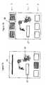
- Fig. 2a and 2bThere are two variants of the in Fig. 1 shown basic module structure shown.
- Fig. 2aIn addition to the handling module 1, the feed module 2 and the output module 7, a mounting module 6 is provided. At this workpieces can for example be processed and / or assembly steps are carried out on the workpieces. In this case, the workpieces of the handling module can first be passed to the assembly module, and be given by the latter via the handling module back to the output module 7.
- Fig. 2ba variant is shown in which the handling module 1 is connected via a transfer module 8 with a Palletierzelle 9 in combination.
- the transfer modulecan be, for example, a conveyor belt on which palletizing baskets can be transported to the palletizing cell.
- the workpiecescan then be first placed in the Palletierkörbe in the area of the transfer module 8.
- the Palletierkörbebe transported into the Palletierzelle 9, for which preferably a corresponding transport device is provided.
- the transfer modulecan either be attached to a palletizing cell or it can be integrated as a transfer module in a palletizing cell and thus enable a direct input into the palletising cell.
- the handling moduleAs a base unit for all variants of the device according to the invention serves the handling module, which with different feed modules can be combined.
- the handling module and feeder modulemay then be extended by different types of feeder module or attached to existing transport, processing and / or assembly units.
- the modular designmakes it possible to meet the diverse and varied requirements of customers with regard to production, processing and assembly lines without a complete new design. Furthermore, the interfaces allow a simple and quick installation on site, since the individual modules delivered pre-assembled and only need to be connected together at the installation site.
- the handling module 1 and the feed module 2each have a cell frame.
- Thisusually comprises a base plate and one or more cell walls, which prevent unauthorized access to the working area of the handling device in a device constructed.
- the cell frames of the individual modulesare connected to each other via mechanical connection points.
- electrical, pneumatic and / or hydraulic interfacescan be provided for connecting the modules.
- the individual modulescan be delivered completely assembled and then connected to each other by a few simple steps.
- the handling module 1has the gripper kinematics, ie an arrangement by means of which the gripper can be moved for removing the workpieces from the container and for depositing them on an intermediate or end tray.
- a robotis used for this, in particular a six-axis robot.
- a surface portalcan also be used.
- the handling modulehas a corresponding control for the gripper kinematics and the gripper.
- the handling modulealso has an operating module with a user interface, via which the controller can be accessed.
- Farthercan be provided an electrical, pneumatic and / or hydraulic supply, in particular in a control cabinet.
- the user interface and the control cabinetare preferably accessible from the outside of the cell walls.
- the inventive device for removing workpieces from the containers in this casehas an object detection device with a sensor.
- a sensorThis is arranged in each case in the region of the feed module and can be arranged above a container to be emptied in order to detect the workpieces in the container.
- itis a 3 D laser scanner.
- the data of the sensorare evaluated in order to identify the individual workpieces and their positions and to determine a suitable for gripping workpiece. Based on the position data of this workpiece is then a path planning for the gripper or for its gripper kinematics, in particular for the robot 10.
- the sensoris for this purpose via an interface with the control of the handling module in connection.
- Fig. 3In this case, first the handling module 1 is shown, which has a robot 10, the user interface 11 and the power supply 12.
- the handling module 1in this case has two open sides, via which it communicates with a feed module 2 and an output module 3.
- the feed module 2has two feed regions arranged side by side for containers, which are each accessible from outside via a door 13.
- the container 66can be inserted, for example, via a forklift in the respective feed or removed from this.
- a hood 14is provided, which is optionally pushed over the feed area for one or the other container can be. If one of the two containers is completely emptied, the hood moves over it, thus releasing the other container for the gripper. The gripper can thus continue seamlessly with the emptying. Through the hood 14, which covers the supply area for the now empty container, this can now be safely removed and replaced by a full container.
- a transport path 15on which the removed from the containers workpieces are stored isolated.
- the transport pathmay optionally have appropriate recordings. In the embodiment, it is a conveyor belt.
- This in Fig. 4 illustrated embodimentdiffers from the in Fig. 3
- the feed moduleis in this case connected to an automated container feed line 16 and an automated container discharge line 17, via which full containers are fed or empty containers are removed.
- the feed direction of the feed line 16is opposite to the discharge direction of the discharge line 17.
- a transverse shuttle 18is provided, via which containers can be moved transversely to the feed or discharge in the direction of movement 19. Containers are thus transported from the feed line 16 into the feed region of the feed module. There, the containers can be emptied by the handling module. An emptied container is then moved via the transverse shuttle 18 to a transfer area for transfer to the discharge line 17, from where the emptied containers are removed. Alternatively, a filled container can also be initially transported via the transverse shuttle within the feed arrangement, and only then take the removal of workpieces from the container.
- a light barrier 20is furthermore provided, which is arranged between the feed module and the feed line 16 and / or discharge line 17. The light barrier prevents the access of persons in the area of the feed module.
- a transport path 21 for the containersis provided as the feed module 2, in particular a conveyor belt via which both the supply of full containers and the removal of empty containers takes place.
- the supply and removaltakes place without change of direction simply by further transport on the transport route.
- the feed module 2preferably has on its narrow sides 22 and 23 openings through which the transport path passes with the containers.
- the turntable 24is rotatable about a vertical axis of rotation 26 to bring the container from a supply area for the container in the working area of the handling module.
- the turntable 24has a partition wall 25 which separates the working area of the gripper from the supply area for the containers.
- the feeding and removal of the container to or from the turntablecan be carried out again via a transport vehicle, for example. A forklift.
- a turntablecan be combined with an automated supply and / or discharge line for the containers.
- an intermediate station 27is furthermore provided in the region of the handling module 1, on which the gripper of the handling module can deposit workpieces which are removed from the containers in the region of the feed module and, if necessary, grasp them again.
- the intermediate stationallows a more precise grip and thus a more accurate filing in the region of the output module.
- feed module 2can be used any feed module, which in Fig. 7a and 7b is shown only schematically.
- any output modulecan be used.
- a transport path 15is used as the output module.
- Fig. 7bis provided as a dispensing module 3, however, a Palletierzelle 28, in which the workpieces are stored.
- Fig. 8a further embodiment is shown, in which the supply and removal of the container via a conveyor belt 21 takes place. Furthermore, a clipboard 27 is provided here in the region of the handling module. The deposit takes place in Palletierkörbe 29, which are moved over a transport path 28 to a Palletierzelle.
- Fig. 9an arrangement is shown in which a plurality of handling modules 1 with a single dispensing module 34, in the embodiment again a conveyor belt, combined.
- the handling moduleswork in parallel, and put each individual workpieces on the output module 34 from.
- the individual handling modules 1are each combined with separate feed modules 35 and thus form removal units 30 to 33.
- two removal units 30 and 32are provided on opposite sides of the conveyor belt 34, so that the loading takes place from opposite sides.
- two removal units along the conveyor belt 34are arranged one behind the other.
- Fig. 10an embodiment is shown in which also several handling modules are used. However, these are connected in series, so that the workpieces are each handled successively by two different handling modules. This allows in particular an increase in the grip accuracy when placing on the end tray.
- the handling modules 36 and 37are provided, which are combined via an intermediate module 38 with an intermediate station.
- the individual modulescan be as in Fig. 10 shown schematically offset offset with each other, but preferably in alignment.
- the arrangement of the two handling modules 36 and 37 and the intermediate module 38is then combined with a feed module 39 and an output module 40.
- the first handling module 37removes workpieces from the containers in the region of the feed module 39 and places them on the intermediate station of the intermediate module 38, from where they are gripped again via the second handling module 36 and deposited in the region of the dispensing module 40.
- the feed modulecan interact with a driverless transport system.
- a robot moduleaccording to the present invention is shown, which can be used for example as a handling module in a device according to the invention for the removal of workpieces from a container, as has been shown above.
- the robot modulecan also be used independently of this application in a variety of tasks.
- the robot module 1comprises a cell frame, which consists of a bottom plate 41 and the cell walls 42 and 43. On the bottom plate while the robot 10 is mounted.
- the robot 10 in the exemplary embodimentis a six-axis industrial robot.
- the bottom plate 41is rectangular, wherein the two cell walls 42 and 43 are arranged on opposite narrow sides of the bottom plate 41.
- the two long sides of the robot moduleare open.
- the working area of the robot 10extends beyond the area of the robot module through the open sides into the adjacent area.
- the robot module 1can be combined with other modules which, for example, provide or receive workpieces that are processed and / or handled by the robot.
- the cell wallsare constructed in the embodiment of corner struts 46, which are connected to each other via transverse struts 47. Furthermore, the cell walls a disguise on. The cell walls prevent access to the working space of the robot 10.
- a control module for the robotis integrated in the robot module. Furthermore, the robot module has a user interface, which is arranged in the exemplary embodiment on an outer wall of the cell wall 42.
- the interfacehas a display 44 and input elements.
- a touch screen 45is provided as an input / output member. Via the user interface, the control module can be accessed and in particular the movement of the robot can be controlled.
- the robot modulehas an electrical, pneumatic and / or hydraulic supply 12, which is accessible from the outside via a control cabinet arranged in the region of the other cell wall 43.
- itis an energy supply not only for the robot or the robot module itself, but also for other modules that can be connected via appropriate interfaces.
- the robot module according to the inventioncan be connected to other modules to form a processing, assembly and / or handling unit.
- the other modulesalso have a cell frame, which can be mechanically connected to the cell frame of the robot module.
- the cell frame of the robot module shown in the embodimenthas mechanical connection points 48 for connection to other modules. These are provided on the corner struts 46. In the exemplary embodiment, these are screw domes 49, which can be pushed through corresponding openings in the cell frame of a further module and can be screwed thereto.
- further modules for power supplycan be connected to the robot module.
- a pneumatic and / or hydraulic interface 50provided, via which a further module can be connected to the hydraulic and / or pneumatic supply of the robot module.
- the robot modulehas a hydraulic supply, it preferably comprises a pump which provides high-pressure hydraulic fluid. If a pneumatic supply is provided, then this preferably comprises a compressor which provides compressed air.
- the electrical connection of a further module via the electrical supply of the robot modulecan take place.
- an electrical interfaceis also provided for this purpose.
- an interface to the control module of the robotcan be provided, via which the operation of the robot module can be coordinated with the operation of other modules.
- the further modulemay itself have a controller which communicates via the interface with the control module of the robot module 1, preferably communicating bidirectionally.
- the actuation of actuators of a further modulecan also take place via the control module of the robot module.
- sensor data from sensors which are arranged in a further modulecan be evaluated via the control module of the robot module.
- the robot moduleis designed in such a way that it can be delivered completely pre-assembled as a unit to the installation site.
- the cell frame for transportoptionally via a longitudinal strut, which connects the cell walls in their upper region, stiffened.
- the transport of the robot moduleThis can be done either hanging, for example by hooks are connected to the longitudinal strut or the cell walls, or by the robot module is transported hanging on the robot.
- the robot modulecan be transported, for example via a forklift, which engages under the bottom plate.
- the robot modulealready has a complete wiring of the robot with the control module, the power supply and the user interface. As a result, only a few assembly steps are to be carried out at the installation site.
- the other modulesare preassembled accordingly and only have to be mechanically connected to the robot module and connected via the corresponding interfaces with the power supply and / or the control module of the robot module.
- Feed module 2 and robot module or handling module 1preferably form a device for removing workpieces arranged in a container, in particular for removing workpieces disposed in a container in a disorderly manner.
- the feed module 2also has a cell frame, which can be connected to the cell frame of the handling module 1.
- the cell framehas a bottom plate 51 and cell walls 52, 53 and 54.
- one side of the feeder moduleis open, and is connected to an open side of the handling module so that the robot 10 can operate in the area of the feeder module.
- the cell frame of the feed modulein turn has corner struts 56, which communicate with each other via transverse struts 47 and longitudinal struts.
- Farther Covers or windowsare also provided here, which protect the area of the feed module from unauthorized access.
- the arranged on the open side of the cell frame corner struts 46can be mechanically connected to the corner struts 46 of the cell frame of the robot module, in particular on the in Fig. 12a illustrated attachment points.
- connection to the power supply of the robot moduleis via the in Fig. 12b shown interface 50 which is connected to a corresponding interface 70 of the feed module.
- the interface 70 of the feed moduleis arranged in the interior of the feed module and accessible via a door in an outer wall. Furthermore, sensors and / or actuators of the feed module can be connected to the control module of the robot module via an electronic interface, not shown.
- the feed module 2is also completely pre-assembled and has a complete wiring, which only makes a connection with the interfaces of the robot module necessary.
- the feed modulecan be hung for example via the holes 48 to a hook and transported hanging. Alternatively, a transport via a forklift is also conceivable here.
- Fig. 14 . 15 and 16Now, the combination of the handling module 1 and the feed module 2 is shown, which together form a device for removing workpieces from containers 66.
- the handling module 1is still connected on its side facing the feeder module free side with an output module 3, which will be discussed in more detail later.
- the feed moduleforms a feed arrangement for providing containers, from which the robot can remove workpieces, which can also be used independently of the modular construction according to the invention.
- the feed arrangement formed by the feed moduleis accessible on one side for the provision and removal of containers.
- sliding doors 55are provided for this, which are embedded in the cell wall 54.
- two supply areas provided side by side in the feed arrangementare accessible to one container each.
- the containerscan be set for example via a forklift 65 in the feed or removed after emptying from this.
- the provision of two containershas the advantage that after emptying a first container, the device can proceed immediately with the emptying of the second container without the removal operation must be interrupted to replace the container. Rather, the empty container can be removed and replaced by a full container while the other container is emptied.
- a displaceable hood 57is provided, which can be pushed either over the feed area for the first container or the feed area for the second container, and thus separates it from the working space of the gripper.
- the doors 55are preferably configured such that they can only be opened when the feed region assigned to the respective door is separated from the working region of the gripper via the displaceable hood 47. This ensures that there is no risk of injury when removing and setting a container in the feed arrangement.
- the inventive device for removing workpieces from the containersin this case has an object detection device with a sensor 63, which can be arranged above the respective container and detects the workpieces in the container.
- a sensor 63which can be arranged above the respective container and detects the workpieces in the container.
- itis a 3 D laser scanner.
- the data of the sensor arrangementare evaluated in order to identify the individual workpieces and their positions and to determine a suitable workpiece for gripping. Based on the position data of this workpiece is then a path planning for the gripper or for its gripper kinematics, in particular for the robot 10th
- the sensor arrangement 63is arranged movable in the feed arrangement.
- a movement arrangement 64is provided, along which the sensor 63 can optionally be arranged above the first and the second container.
- Thishas the advantage that only one sensor arrangement for detecting the workpieces must be used, since these can be driven over the respective container depending on the container, which is to be emptied.
- the sensor arrangementcan be moved away from an area above the container so that the working area of the gripper is not restricted by the sensor arrangement. After a workpiece has been removed, the sensor assembly is then moved over the container again to detect the remaining workpieces.
- the sensor arrangement 63is connected to the control module of the robot module, wherein the data of the sensor module are evaluated via the control module.
- the handling moduleis as in Fig. 15 and 16 shown connected to an output module on the open side opposite the feed module.
- thisalso has a cell frame, which is connected to the cell frame of the handling module 1.
- the output unitin this case has a transport path on which the gripper of the handling unit deposits the workpieces removed from the container.
- the transport routeis a roller conveyor. On this nests can be transported if necessary, in which the workpieces are stored.
- the cell frame of the dispensing modulealso protects against unauthorized access to the working area of the robot 10.
- doors 71are provided, through which the interior of the cell formed by the feed module, handling module and dispensing module can be entered.
- the device according to the invention for the removal of workpieces from a container with little design and installation effortcan be used in a variety of different areas.
- the handling module according to the inventioncan be combined with output units already provided by the customer, so that only a corresponding connection of the handling module, in particular via the construction of a cell frame, has to be newly designed for the output module.
- the handling modulecan also be combined with the customer already existing existing feed modules.
- the robot module according to the inventioncan also be used in other applications for the simple and inexpensive construction of a robot cell.
- itcan be combined with processing and / or assembly modules.
Landscapes
- Engineering & Computer Science (AREA)
- Robotics (AREA)
- Mechanical Engineering (AREA)
- Manipulator (AREA)
- Toys (AREA)
Abstract
Translated fromGerman
Description
Translated fromGermanDie vorliegende Erfindung betrifft ein Robotermodul. Insbesondere kann das erfindungsgemäße Robotermodul dabei als Handhabungsmodul eingesetzt werden, insbesondere zum Entnehmen von in einem Behälter angeordneten Werkstücken. Das Robotermodul kann jedoch auch zu anderen Zwecken eingesetzt werden.The present invention relates to a robot module. In particular, the robot module according to the invention can be used as a handling module, in particular for removing workpieces arranged in a container. However, the robot module can also be used for other purposes.
Roboter werden im Bereich der Handhabung, Bearbeitung und / oder Montage von Werkstücken in vielfältigen Bereichen und Anwendungsfällen eingesetzt.Robots are used in the field of handling, machining and / or assembly of workpieces in a variety of fields and applications.
Dabei erfolgt die Konstruktion und Zusammenstellung einzelner Einheiten eines Handhabungs-, Bearbeitungs- und / oder Montagesystems üblicherweise individuell und je nach den konkreten Anforderungen. Neben dem Roboter sowie weiteren Einheiten, welche der Bereitstellung, Handhabung, Bearbeitung, Montage und / oder dem Abtransport der Werkstücke dienen, sind dabei üblicherweise weiterhin Zellenwände vorgesehen. Diese verhindern den unbefugten Zutritt in den Arbeitsbereich des Roboters oder der übrigen Komponenten. Auch diese werden üblicherweise separat und jeweils individuell für den einzelnen Einsatz konstruiert und montiert.The construction and assembly of individual units of a handling, processing and / or mounting system usually takes place individually and depending on the specific requirements. In addition to the robot and other units which serve the provision, handling, processing, assembly and / or removal of the workpieces, cell walls are usually still provided. These prevent unauthorized access to the working area of the robot or the other components. These too are usually designed and assembled separately and individually for the individual application.
Aufgabe der vorliegenden Erfindung ist es, die Planung, Konstruktion und Bereitstellung von Einheiten, in welchen Roboter zum Einsatz kommen, zu vereinfachen.The object of the present invention is to simplify the planning, construction and provision of units in which robots are used.
Erfindungsgemäß wird diese Aufgabe durch ein Robotermodul gemäß Anspruch 1, ein Zuführmodul gemäß Anspruch 9, ein Ausgabemodul gemäß Anspruch 14 und eine Handhabungsanlage gemäß Anspruch 15 gelöst.According to the invention, this object is achieved by a robot module according to
Die vorliegende Erfindung zeigt dabei ein Robotermodul mit einem Zellenrahmen und einem Roboter, wobei der Zellenrahmen eine Bodenplatte aufweist, an welcher Roboter montiert ist, und mindestens eine mit der Bodenplatte verbundene Zellenwand und wobei das Robotermodul mit einem Steuermodul für den Roboter ausgestattet ist.The present invention shows a robot module with a cell frame and a robot, wherein the cell frame has a bottom plate on which robot is mounted, and at least one connected to the bottom plate cell wall and wherein the robot module is equipped with a control module for the robot.
Das erfindungsgemäße Robotermodul stellt damit eine Komponente zur Verfügung, welche in einer Vielzahl von Anwendungen zum Einsatz kommen kann, ohne dass jedes Mal neu das Zusammenspiel von Robotermodul, Zellenrahmen und Steuermodul neu konstruiert und hergestellt werden müsste. Das Robotermodul kann damit in größerer Stückzahl gefertigt werden, und jeweils durch Kombination mit anderen Modulen an den jeweiligen Einsatzzweck angepasst werden. Hierdurch ergeben sich erhebliche Vorteile bei der Geschwindigkeit und den Kosten der Konstruktion, der Herstellung und der Endmontage.The robot module according to the invention thus makes available a component which can be used in a large number of applications without the interaction of the robot module, cell frame and control module having to be newly designed and produced every time. The robot module can thus be manufactured in larger quantities, and be adapted in each case by combination with other modules to the respective application. This results in significant advantages in the speed and cost of construction, manufacturing and final assembly.
Vorteilhafterweise ist das Robotermodul dabei so ausgestattet, dass es am Montageort nur noch mit anderen Modulen verbunden werden muss. Bevorzugt müssen dabei am Robotermodul selbst keine Montagearbeiten mehr durchgeführt werden. Insbesondere kann der Roboter damit bereits komplett mit der Steuerung verkabelt sein. Hierdurch verringern sich die Montagezeiten vor Ort erheblich. Bevorzugt ist das Robotermodul damit "hakenfertig" vormontiert.Advantageously, the robot module is equipped so that it only has to be connected to other modules at the installation site. Preferably no assembly work has to be carried out on the robot module itself. In particular, the robot can thus already be completely wired to the controller. As a result, the installation times on site are significantly reduced. Preferably, the robot module is thus preassembled "ready to hook".
Weiterhin vorteilhafterweise ist das Robotermodul dabei als Ganzes transportierbar. Beispielsweise kann dabei ein Gabelstapler eingesetzt werden, welcher unter die Bodenplatte fährt und das Robotermodul als Ganzes transportiert. Alternativ oder zusätzlich kann das Robotermodul auch hängend transportierbar sein.Furthermore advantageously, the robot module can be transported as a whole. For example, while a forklift can be used, which under the Bottom plate moves and transports the robot module as a whole. Alternatively or additionally, the robot module can also be transported hanging.
Der Roboter des erfindungsgemäßen Robotermoduls weist bevorzugt einen Arbeitsbereich auf, welcher größer als die Grundfläche der Bodenplatte ist. Insbesondere kann der Roboter dabei über mindestens eine freie Seite des Zellenrahmens Werkstücke, welche außerhalb des Robotermoduls angeordnet sind, handhaben, insbesondere greifen und / oder bearbeiten.The robot of the robot module according to the invention preferably has a working area which is larger than the base area of the floor panel. In particular, the robot can handle, in particular grasp and / or process workpieces which are arranged outside the robot module via at least one free side of the cell frame.
Bevorzugt ist der Arbeitsbereich des Roboters dabei so groß, dass er zu zwei Seiten des Zellenrahmens sich über dessen Grundfläche hinaus erstreckt. Insbesondere kann das Robotermodul dabei so ausgestaltet sein, dass ein Greifer des Robotermoduls Werkstücke aus einem Bereich, welcher außerhalb einer ersten offenen Seite des Zellenrahmens angeordnet ist, entnehmen und in einen zweiten Bereich, welcher außerhalb einer zweiten offenen Seite des Zellenrahmens angeordnet ist, ablegen kann.Preferably, the working area of the robot is so large that it extends to two sides of the cell frame beyond its base. In particular, the robot module may be designed such that a gripper of the robot module can remove workpieces from a region which is arranged outside a first open side of the cell frame and can deposit them in a second region, which is arranged outside a second open side of the cell frame ,
Bevorzugt ist der Zellenrahmen nach oben hin offen.Preferably, the cell frame is open at the top.
Vorteilhafterweise weist der Zellenrahmen des erfindungsgemäßen Robotermoduls mechanische Verbindungspunkte zur Verbindung mit weiteren Modulen auf. Hierdurch kann am Aufstellort eine einfache mechanische Verbindung zwischen den einzelnen Modulen hergestellt werden. Bei den mechanischen Verbindungspunkten kann es sich beispielsweise um Bolzen und / oder Bolzenaufnahmen handeln, und / oder Schrauben und / oder Schraubdome, über welche eine mechanische Verbindung zwischen mehreren Modulen erfolgt.Advantageously, the cell frame of the robot module according to the invention has mechanical connection points for connection to further modules. As a result, a simple mechanical connection between the individual modules can be made at the installation. The mechanical connection points may be, for example, bolts and / or bolt receptacles, and / or screws and / or screw domes, via which a mechanical connection between a plurality of modules takes place.
Weiterhin kann das erfindungsgemäße Robotermodul eine Elektrik-, Pneumatik- und / oder Hydraulikversorgung aufweisen. Insbesondere kann dabei ein Druckluftgenerator und / oder eine Hydraulik-Hochdruckversorgung vorgesehen sein, und / oder eine Elektrikversorgung, welche ans Netz angeschlossen wird und die Komponenten des Robotermoduls mit elektrischer Energie versorgt.Furthermore, the robot module according to the invention can have an electrical, pneumatic and / or hydraulic supply. In particular, a compressed air generator and / or a high-pressure hydraulic supply can be provided, and / or an electrical supply which is connected to the mains and supplies the components of the robot module with electrical energy.
Weiterhin bevorzugt kann das Robotermodul eine Elektrik-, Pneumatik- und / oder Hydraulikschnittstelle zur Verbindung mit weiteren Modulen aufweisen. Durch die Schnittstelle können die weiteren Module bevorzugt auf die Elektrik-, Pneumatik- und / oder Hydraulikversorgung des Robotermoduls zugreifen. Die weiteren Module benötigen hierdurch keine eigene Versorgung, was die Kosten verringert und die Montage vereinfacht.Furthermore, the robot module can preferably have an electrical, pneumatic and / or hydraulic interface for connection to further modules. Through the interface, the other modules can preferably access the electrical, pneumatic and / or hydraulic supply of the robot module. The other modules do not require their own supply, which reduces costs and simplifies installation.
Weiterhin kann das Robotermodul eine Schnittstelle aufweisen, welche eine Koordinierung des Betriebs des Robotermoduls mit anderen Modulen erlaubt. Insbesondere handelt es sich dabei um eine Schnittstelle des Steuermoduls für den Roboter. Insbesondere erlaubt die Schnittstelle dabei einen Datenaustausch und / oder die Absendung und / oder Entgegennahme von Steuerbefehlen und / oder Sensordaten. Weiterhin kann das Robotermodul eine Schnittstelle für ein Fertigungssteuerungssystem aufweisen, welche eine Koordinierung des Betriebs mit einem weiteren Fertigungssystem ermöglicht.Furthermore, the robot module can have an interface which allows a coordination of the operation of the robot module with other modules. In particular, this is an interface of the control module for the robot. In particular, the interface allows a data exchange and / or the sending and / or receiving of control commands and / or sensor data. Furthermore, the robot module can have an interface for a production control system, which enables coordination of the operation with another production system.
Bevorzugt weist die Bodenplatte des Zellenrahmens eine rechteckige Form auf. Hierdurch ist die Kombination mit den Bodenplatten weiterer Module vereinfacht. Bevorzugt weist die Bodenplatte dabei eine längere und eine kürzere Seite auf.Preferably, the bottom plate of the cell frame has a rectangular shape. This simplifies the combination with the bottom plates of further modules. Preferably, the bottom plate has a longer and a shorter side.
Weiterhin kann vorgesehen sein, dass Zellenrahmen mindestens zwei Zellenwände aufweist. Die Zellenwände sind dabei bevorzugt mit der Bodenplatte verbunden. Die Zellenwände sorgen dabei bei einer aus dem Robotermodul und weiteren Modulen aufgebauten fertigen Anlage dafür, dass unbefugte Personen keinen Zutritt zum Arbeitsbereich des Robotermoduls erhalten. Bevorzugt weist der Zellenrahmen dabei auf zwei Seiten Zellenwände auf, während er auf zwei Seiten offen ist. Bevorzugt kann das Robotermodul dabei an den Seiten, an welchen keine Zellenwände vorgesehen sind, mit weiteren Modulen verbunden werden. Gegebenenfalls kann der Zellenrahmen auch auf drei Seiten Zellenwände aufweisen und nur an einer Seite hin offen sein. In diesem Fall wird das Robotermodul nur auf einer Seite mit einem oder mehreren Modulen verbunden.Furthermore, it can be provided that the cell frame has at least two cell walls. The cell walls are preferably connected to the bottom plate. In the case of a finished system constructed from the robot module and further modules, the cell walls ensure that unauthorized persons do not gain access to the working area of the robot module. The cell frame preferably has cell walls on two sides, while it is open on two sides. Preferably, the robot module can be connected to other modules on the sides, on which no cell walls are provided. Optionally, the cell frame may also have cell walls on three sides and be open only on one side. In this case, the robot module is connected to one or more modules on one side only.
In einer möglichen Ausführungsform der vorliegenden Erfindung sind die beiden Zellenwände dabei auf gegenüberliegenden Seiten der Bodenplatte angeordnet. Besonders bevorzugt sind die beiden Zellenwände dabei auf gegenüberliegenden Schmalseiten der Bodenplatte angeordnet. Hierdurch stehen die längeren Seiten der Bodenplatte zur Verbindung mit weiteren Modulen zur Verfügung, und damit ein entsprechend breiter Bereich, über welchen der Roboter des Robotermoduls mit den Komponenten der anderen Module zusammenwirken kann.In one possible embodiment of the present invention, the two cell walls are arranged on opposite sides of the bottom plate. Particularly preferably, the two cell walls are arranged on opposite narrow sides of the bottom plate. As a result, the longer sides of the base plate are available for connection to other modules, and thus a correspondingly wide area over which the robot of the robot module can interact with the components of the other modules.
In einer zweiten Ausführungsform können die beiden Zellenwände auch auf angrenzenden Seiten der Bodenplatte angeordnet sein. Bevorzugt werden in diesem Fall weitere Module über Eck mit dem Robotermodul verbunden.In a second embodiment, the two cell walls can also be arranged on adjacent sides of the bottom plate. In this case, further modules are preferably connected via corner to the robot module.
Der Zellenrahmen des erfindungsgemäßen Robotermoduls kann dabei vertikal verlaufende Eckstreben aufweisen. Bevorzugt sind die Eckstreben dabei über horizontal verlaufende Querstreben verbunden, um Zellenwände zu bilden. Hierdurch ergibt sich eine mechanisch stabile Konstruktion. Vorteilhafterweise sind die Eckstreben dabei in ihrem unteren Bereich mit der Bodenplatte verbunden.The cell frame of the robot module according to the invention can have vertically extending corner struts. Preferably, the corner struts are connected via horizontally extending transverse struts to form cell walls. This results in a mechanically stable construction. Advantageously, the corner struts are connected in their lower region with the bottom plate.
Bevorzugt weisen die Eckstreben mechanische Verbindungspunkte zur Verbindung mit mindestens einem weiteren Modul auf. Insbesondere kann es sich dabei um jene mechanische Verbindungspunkte handeln, welche bereits oben näher dargestellt wurden.Preferably, the corner struts have mechanical connection points for connection to at least one further module. In particular, these may be those mechanical connection points which have already been described in more detail above.
Erfindungsgemäß kann vorgesehen sein, dass mindestens zwei der Seitenwände des Zellenrahmens in einem oberen Bereich über eine Transportstrebe miteinander verbindbar sind. Hierdurch wird der Zellenrahmen für den Transport versteift. Bevorzugt wird die Transportstrebe dann am Montageort wieder abgenommen, sodass sie den Arbeitsbereich des Roboters nicht einschränkt.According to the invention, it can be provided that at least two of the side walls of the cell frame can be connected to each other in an upper region via a transport strut. This stiffens the cell frame for transport. Preferably, the transport strut is then removed again at the installation site, so that it does not restrict the working range of the robot.
Das erfindungsgemäße Robotermodul weist bevorzugt ein Bedienmodul auf. Insbesondere kann das Bedienmodul dabei eine Ein- / Ausgabeschnittstelle aufweisen.The robot module according to the invention preferably has an operating module. In particular, the operating module can have an input / output interface.
Insbesondere kann dabei ein Display oder ein Monitor vorgesehen sein. Weiterhin bevorzugt sind Eingabeelemente wie eine Tastatur zur Eingabe von Daten oder Steuerbefehlen vorgesehen. Das Bedienmodul ist bevorzugt an einer Außenseite einer Zellwand angeordnet und/ oder kann auch mit einem mobilen Bedienelement ausgestattet sein. Das Bedienmodul erlaubt bevorzugt einen Zugriff auf das Steuermodul.In particular, a display or a monitor can be provided. Further preferred are input elements such as a keyboard for inputting data or control commands. The operating module is preferably arranged on an outer side of a cell wall and / or can also be equipped with a mobile operating element. The operating module preferably allows access to the control module.
Das erfindungsgemäße Robotermodul kann weiterhin einen Schaltschrank aufweisen. Insbesondere kann in dem Schaltschrank die Elektronik-, Pneumatik- und / oder Hydraulikversorgung vorgesehen sein. Bevorzugt ist der Schaltschrank dabei von einer Außenseite einer Zellwand aus zugänglich. Bevorzugt sind dabei das Bedienmodul und der Schaltschrank in zwei unterschiedlichen Zellwänden des Zellenrahmens angeordnet, insbesondere auf gegenüberliegenden Seiten des Zellenrahmens.The robot module according to the invention may further comprise a control cabinet. In particular, the electronic, pneumatic and / or hydraulic supply can be provided in the control cabinet. Preferably, the cabinet is accessible from an outside of a cell wall. Preferably, the operating module and the control cabinet are arranged in two different cell walls of the cell frame, in particular on opposite sides of the cell frame.
Bei dem erfindungsgemäßen Robotermodul handelt es sich bevorzugt um ein Handhabungsmodul, insbesondere zur Handhabung von Werkstücken. Bevorzugt ist der Roboter hierfür mit einem Greifer ausgestattet oder austattbar. Alternativ oder zusätzlich kann das Steuermodul eine Steuerroutine zum Greifen und / oder Ablegen von Werkstücken mittels des Roboters aufweisen.The robot module according to the invention is preferably a handling module, in particular for handling workpieces. For this purpose, the robot is preferably equipped with a gripper or can be replaced. Alternatively or additionally, the control module may have a control routine for gripping and / or depositing workpieces by means of the robot.
In einer möglichen, besonders bevorzugten Ausgestaltung erlaubt das Robotermodul ein Greifen von ungeordnet in einem Behälter angeordneten Werkstücken. Insbesondere kann das Steuermodul des Robotermoduls dabei eine Schnittstelle zu einer Objekterkennungseinrichtung zum Erfassen der Werkstücke im Behälter aufweisen. Weiterhin kann das Steuermodul Steuerroutinen zur Auswertung der Daten der Objekterkennungseinrichtung, zur Pfadplanung und zur Ansteuerung des Greifers aufweisen.In a possible, particularly preferred embodiment, the robot module allows a gripping of randomly arranged in a container workpieces. In particular, the control module of the robot module can have an interface to an object recognition device for detecting the workpieces in the container. Furthermore, the control module may have control routines for evaluating the data of the object recognition device, for path planning and for activating the gripper.
Insbesondere kann das erfindungsgemäße Robotermodul dabei in einer Vorrichtung zur Entnahme von Werkstücken aus einem Behälter eingesetzt werden, wie sie aus der
Ein Robotermodul gemäß der vorliegenden Erfindung kann weiterhin eine Zwischenstation aufweisen, welche an der Bodenplatte des Robotermoduls angeordnet ist und auf welcher Werkstücke, welche von einem Greifer des Robotermoduls gegriffen wurden, abgelegt und von diesem oder einem anderen Greifer wieder aufgenommen werden können.A robot module according to the present invention may further comprise an intermediate station which is arranged on the bottom plate of the robot module and on which workpieces which have been gripped by a gripper of the robot module can be deposited and picked up by this or another gripper.
Weiterhin umfasst die vorliegende Erfindung ein Zwischenmodul, auf welchem eine Zwischenstation zum Ablegen und Wiederaufnehmen eines Werkstücks angeordnet ist. Bevorzugt weist das Zwischenmodul dabei einen Zellenrahmen und eine Zwischenstation auf. Insbesondere kann das Zwischenmodul dabei eine Bodenplatte und mindestens zwei Zellenwände aufweisen. Bevorzugt ist die Zwischenstation dabei an der Bodenplatte angeordnet. Bevorzugt weist das Zwischenmodul dabei zwei offene Seiten auf.Furthermore, the present invention comprises an intermediate module on which an intermediate station for depositing and resuming a workpiece is arranged. The intermediate module preferably has a cell frame and an intermediate station. In particular, the intermediate module may have a bottom plate and at least two cell walls. Preferably, the intermediate station is arranged on the bottom plate. The intermediate module preferably has two open sides.
Weiterhin umfasst die vorliegende Erfindung eine Zwischenstation zum Ablegen und Wiederaufnehmen eines Werkstücks, welche in einem Ausgabe- / Bearbeitungs- und/oder Montagemodul integrierbar ist.Furthermore, the present invention comprises an intermediate station for depositing and resuming a workpiece, which can be integrated in an output / processing and / or assembly module.
Die vorliegende Erfindung umfasst weiterhin ein Zuführmodul mit einem Zellenrahmen und einer Anordnung zur Bereitstellung eines Behälters mit Werkstücken. Auch das Zuführmodul erlaubt damit eine besonders einfache Konstruktion, Herstellung und Montage einer Vorrichtung zur Handhabung von Werkstücken. Insbesondere müssen auch hier der Zellenrahmen und die Anordnung zur Bereitstellung eines Behälters mit Werkstücken nicht mehr jeweils separat konstruiert und montiert werden. Durch das erfindungsgemäße Zuführmodul ergeben sich damit im Wesentlichen die gleichen Vorteile, welche bereits oben im Hinblick auf das erfindungsgemäße Robotermodul näher dargestellt wurden.The present invention further includes a delivery module having a cell frame and an assembly for providing a container with workpieces. Also, the feed module thus allows a particularly simple design, manufacture and installation of a device for handling workpieces. In particular, the cell frame and the arrangement for providing a container with workpieces no longer have to be separately constructed and mounted here as well. As a result of the feed module according to the invention, essentially the same advantages result, which have already been described in more detail above with regard to the robot module according to the invention.
Insbesondere dient das Zuführmodul dabei zur Zuführung von Behältern mit Werkstücken, aus welchen ein erfindungsgemäßes Robotermodul Werkstücke entnehmen kann. Bevorzugt sind dabei das erfindungsgemäße Zuführmodul und das erfindungsgemäße Robotermodul miteinander verbindbar.In particular, the feed module serves to supply containers with workpieces, from which a robot module according to the invention remove workpieces can. In this case, the feed module according to the invention and the robot module according to the invention are preferably connectable to one another.
Bevorzugt weist der Zellenrahmen des Zuführmoduls dabei mechanische Verbindungspunkte auf. Insbesondere erlauben die Verbindungspunkte dabei eine Verbindung mit Verbindungspunkten des Robotermoduls.In this case, the cell frame of the feed module preferably has mechanical connection points. In particular, the connection points allow a connection with connection points of the robot module.
Weiterhin vorteilhafterweise kann das erfindungsgemäße Zuführmodul eine Elektrik-, Pneumatik- und / oder Hydraulikschnittstelle zur Verbindung mit einer entsprechenden Schnittstelle des erfindungsgemäßen Robotermoduls aufweisen. Insbesondere kann das Zuführmodul dabei über die Schnittstelle mit elektrischer, pneumatischer und / oder hydraulischer Energie versorgt werden. Hierdurch benötigt das Zuführmodul in einer bevorzugten Ausgestaltung keine eigene Elektrik-, Pneumatik- und / oder Hydraulikversorgung.Further advantageously, the feed module according to the invention may have an electrical, pneumatic and / or hydraulic interface for connection to a corresponding interface of the robot module according to the invention. In particular, the feed module can be supplied via the interface with electrical, pneumatic and / or hydraulic energy. As a result, the feed module in a preferred embodiment does not require its own electrical, pneumatic and / or hydraulic supply.
Weiterhin kann das Zuführmodul eine Schnittstelle aufweisen, welche eine Koordinierung des Betriebs des Zuführmoduls mit anderen Modulen erlaubt. Insbesondere erlaubt die Schnittstelle dabei eine Verbindung mit dem Steuermodul des Robotermoduls. Dabei kann in einer möglichen Ausführungsform vorgesehen sein, dass im Zuführmodul angeordnete Aktoren über das Steuermodul des Robotermoduls angesteuert werden. Weiterhin kann vorgesehen sein, dass das Steuermodul Daten von Sensoren, welche im Zuführmodul angeordnet sind, erhält. In einer alternativen Ausführungsform kann das Zuführmodul jedoch auch ein eigenes Steuermodul aufweisen, welches Aktoren des Zuführmoduls ansteuert und / oder Sensoren des Zuführmoduls auswertet, wobei bevorzugt ein solches Steuermodul des Zuführmoduls über eine Schnittstelle mit dem Steuermodul des Robotermoduls kommuniziert. Weiterhin kann das Zuführmodul eine Schnittstelle für ein Fertigungssteuerungssystem aufweisen, welche eine Koordinierung des Betriebs mit einem weiteren Fertigungssystem ermöglicht.Furthermore, the feed module can have an interface which allows a coordination of the operation of the feed module with other modules. In particular, the interface allows a connection to the control module of the robot module. In one possible embodiment, it may be provided that actuators arranged in the feed module are actuated via the control module of the robot module. Furthermore, it can be provided that the control module receives data from sensors which are arranged in the feed module. In an alternative embodiment, however, the feed module can also have its own control module which actuates actuators of the feed module and / or evaluates sensors of the feed module, wherein preferably such a control module of the feed module communicates via an interface with the control module of the robot module. Furthermore, the feed module may have an interface for a production control system, which allows a coordination of the operation with another manufacturing system.
Das erfindungsgemäße Zuführmodul weist bevorzugt einen Zellenrahmen mit einer Bodenplatte auf, an welcher die Anordnung zur Bereitstellung eines Behälters mit Werkstücken angeordnet ist. Weiterhin kann vorgesehen sein, dass der Zellenrahmen des Zuführmoduls mindestens an zwei und bevorzugt an drei Seiten Zellenwände aufweist und auf mindestens einer Seite hin offen ist. Insbesondere kann der Zellenrahmen dabei bevorzugt über die offene Seite mit dem Robotermodul verbunden werden. Besonders bevorzugt erfolgt die Verbindung zwischen Robotermodul und Zuführmodul dabei in der Weise, dass ein Greifer des Robotermoduls in mindestens einen Behälter, welcher durch die Anordnung zur Bereitstellung eines Behälters bereitgestellt wird, greifen und aus diesem Werkstücke entnehmen kann.The feed module according to the invention preferably has a cell frame with a bottom plate, on which the arrangement for providing a container with Workpieces is arranged. Furthermore, it can be provided that the cell frame of the feed module has cell walls at least at two and preferably at three sides and is open on at least one side. In particular, the cell frame can preferably be connected to the robot module via the open side. Particularly preferably, the connection between robot module and feed module takes place in such a way that a gripper of the robot module in at least one container, which is provided by the arrangement for providing a container, grab and remove from this workpieces.
Erfindungsgemäß kann vorgesehen sein, dass mindestens zwei der Seitenwände des Zellenrahmens in einem oberen Bereich über eine Transportstrebe miteinander verbindbar sind. Hierdurch wird der Zellenrahmen für den Transport versteift. Bevorzugt wird die Transportstrebe dann am Montageort wieder abgenommen, sodass sie den Arbeitsbereich des Roboters nicht einschränkt.According to the invention, it can be provided that at least two of the side walls of the cell frame can be connected to each other in an upper region via a transport strut. This stiffens the cell frame for transport. Preferably, the transport strut is then removed again at the installation site, so that it does not restrict the working range of the robot.
Die Anordnung zur Bereitstellung eines Behälters mit Werkstücken ist dabei bevorzugt auf mindestens einer Seite von außen zugänglich, insbesondere über eine auf mindestens einer Seite angeordneten Türe und / oder einen auf mindestens einer Seite angeordneten automatischen Zu- und / oder -Abführstrecke. Bevorzugt werden über diese Seite volle Behälter zugeführt und leere Behälter wieder abgeführt. Bevorzugt liegt die Seite, von welcher aus die Anordnung zur Bereitstellung eines Behälters mit Werkstücken von außen zugänglich ist, der offenen Seite gegenüber.The arrangement for providing a container with workpieces is preferably accessible from the outside on at least one side, in particular via a door arranged on at least one side and / or an automatic feed and / or removal path arranged on at least one side. Preferably, full containers are supplied via this page and empty containers are removed again. Preferably, the side from which the arrangement for providing a container with workpieces is accessible from the outside, the open side opposite.
Die Zu- und / oder Abführrichtung der Behälterzu- und / oder -abführstrecke kann dabei je nach Ausgestaltung entweder parallel zu der offenen Seite angeordnet sein, oder senkrecht zu dieser, wobei in diesem Fall die Transportrichtung der Behälterzuführstrecke gegenläufig zur Transportrichtung der Behälterabführstrecke ist.Depending on the configuration, the supply and / or discharge direction of the container supply and / or discharge path may be arranged either parallel to the open side, or perpendicular thereto, in which case the transport direction of the container supply path is opposite to the transport direction of the container removal path.
In einer besonders bevorzugten Ausführung der vorliegenden Erfindung handelt es sich bei der offenen Seite bevorzugt um eine Breitseite des Zuführmoduls. Bevorzugt ist damit eine Breitseite des Zuführmoduls offen, auf der gegenüberliegenden Seite erfolgt die Bereitstellung und Abführung der Behälter, und auf den Schmalseiten sind jeweils Zellwände vorgesehen, welche den Arbeitsbereich des Roboters abtrennen.In a particularly preferred embodiment of the present invention, the open side is preferably a broad side of the feed module. Thus, a broad side of the feed module is preferably open on the opposite side, the provision and discharge of the container, and on the narrow sides each cell walls are provided, which separate the working area of the robot.
In einer bevorzugten Ausgestaltung der vorliegenden Erfindung kann die Anordnung zur Bereitstellung eines Behälters mit Werkstücken mindestens zwei Behälter aufnehmen. Dies erlaubt ein schnelles Weiterarbeiten, nachdem ein erster Behälter entleert wurde.In a preferred embodiment of the present invention, the arrangement for providing a container with workpieces can accommodate at least two containers. This allows a fast working after a first container has been emptied.
In einer möglichen Ausführungsform der vorliegenden Erfindung weist das Zuführmodul eine Trennvorrichtung auf, über welche ein Zuführbereich für einen Behälter von einem Arbeitsbereich des Greifers trennbar ist. Eine solche Trennvorrichtung ist insbesondere dann von Vorteil, wenn die Behälter einzeln beispielsweise über ein Transportfahrzeug zugeführt und wieder abgeführt werden. Die Trennvorrichtung sorgt in diesem Fall dafür, dass der Roboter weiterhin Werkstücke aus einem Behälter, welcher sich im Arbeitsbereich des Roboters befindet, entnehmen kann, während im Zuführbereich ein neuer Behälter zugeführt oder ein entleerter Behälter entnommen wird.In one possible embodiment of the present invention, the feed module has a separating device, via which a feed region for a container can be separated from a working region of the gripper. Such a separation device is particularly advantageous if the containers are supplied individually, for example via a transport vehicle and discharged again. In this case, the separating device ensures that the robot can continue to remove workpieces from a container which is located in the working area of the robot, while a new container is fed in the feed area or a deflated container is removed.
Insbesondere kann dabei eine Haube vorgesehen sein, welche so im Zuführmodul angeordnet ist, dass sie wahlweise über den Zuführbereich für den einen oder den anderen Behälter bewegt werden kann. Insbesondere kann die Haube dabei verschiebbar und/oder verschwenkbar sein.In particular, it is possible to provide a hood which is arranged in the feed module in such a way that it can optionally be moved over the feed area for one or the other container. In particular, the hood can be displaceable and / or pivotable.
In einer alternativen Ausführungsform kann das Zuführmodul in einer Transportanordnung zum Transport der Behälter im Inneren des Zuführmoduls aufweisen. Insbesondere kann diese Transportanordnung dabei mit einer automatischen Behälterzu- und / oder -abführstrecke zusammenwirken. Die Transportanordnung zum Transport der Behälter im Inneren des Zuführmoduls erlaubt es dabei, einen durch den Roboter entleerten Behälter weiter zu transportieren und der Abführstrecke zuzuführen. In einer möglichen Ausführungsform ist dabei eine Lichtschranke vorgesehen, welche den Zuführbereich absichert.In an alternative embodiment, the feed module can have a transport arrangement for transporting the containers in the interior of the feed module. In particular, this transport arrangement can cooperate with an automatic Behälterzu- and / or -abführstrecke. The transport arrangement for transporting the containers in the interior of the feed module makes it possible to further transport a container emptied by the robot and to feed it to the discharge line. In one possible embodiment, a light barrier is provided which secures the feed area.
Bei der Transportanordnung kann es sich dabei in einer möglichen Ausführungsform um eine Quershuttle handeln, welche die Behälter im Inneren des Zuführmoduls senkrecht zu einer Zu- bzw. Abführrichtung der automatischen Zu- und / oder Abführstrecke verschiebt. Die Behälter werden also auf einer Seite voll zugeführt, im Inneren des Zuführmoduls entleert, und dann über das Quershuttle zu dem Eingangsbereich der Abführstrecke verschoben, von wo aus sie wieder entnommen werden.In a possible embodiment, the transport arrangement may be a transverse shuttle which shifts the containers in the interior of the feed module perpendicular to a feed or discharge direction of the automatic feed and / or discharge path. The containers are thus fully fed on one side, emptied inside the feed module, and then moved via the shuttle shuttle to the input area of the discharge line, from where they are removed again.
Alternativ kann es sich bei der Transportanordnung des Zuführmoduls um einen Drehtisch handeln, auf welchen die Behälter anordenbar sind, wobei die Behälter durch Drehen des Drehtisches von einem Zuführbereich des Zuführmoduls in einen Arbeitsbereich des Greifers des Robotermoduls verfahrbar sind und umgekehrt.Alternatively, the transport arrangement of the feed module can be a turntable on which the containers can be arranged, wherein the containers can be moved by rotating the turntable from a feed region of the feed module into a working region of the gripper of the robot module and vice versa.
Weiterhin kann das Zuführmodul mit einem fahrerlosen Transportsystem zusammenwirken.Furthermore, the feed module can interact with a driverless transport system.
Die vorliegende Erfindung umfasst weiterhin ein Ausgabe-, Bearbeitungs- und / oder Montagemodul zur Verbindung mit einem Robotermodul, wie es oben dargestellt wurde. Insbesondere weist das Ausgabe-, Bearbeitungs- und / oder Montagemodul dabei eine Endablage auf, auf welcher Werkstücke vereinzelt und / oder in einer definierten Position durch einen Greifer des Robotermoduls abgelegt werden können. Weiterhin vorteilhafterweise weist das Modul dabei mechanische Verbindungspunkte zur Verbindung mit einem Robotermodul, wie es oben dargestellt wurde, auf. Ein Ausgabemodul weist dabei bevorzugt eine Transportstrecke für die Werkstücke auf, über welche die Werkstücke abtransportiert werden können. Ein Bearbeitungs- und / oder Montagemodul weist bevorzugt eine Bearbeitungs- und / oder Montageeinheit auf, durch welche Werkstücke bearbeitet und / oder montiert werden können.The present invention further includes an output, processing, and / or assembly module for connection to a robotic module as set forth above. In particular, the output, processing and / or assembly module has an end deposit on which workpieces can be singulated and / or stored in a defined position by a gripper of the robot module. Further advantageously, the module has mechanical connection points for connection to a robot module, as has been shown above. An output module preferably has a transport path for the workpieces over which the workpieces can be removed. A processing and / or assembly module preferably has a processing and / or assembly unit, through which workpieces can be processed and / or mounted.
Das Ausgabe-, Bearbeitungs- und / oder Montagemodul weist bevorzugt einen Zellenrahmen auf, welcher bevorzugt eine Bodenplatte und/oder eine oder mehrere Seitenwände aufweist.The output, processing and / or assembly module preferably has a cell frame, which preferably has a bottom plate and / or one or more side walls.
Erfindungsgemäß kann vorgesehen sein, dass mindestens zwei der Seitenwände des Zellenrahmens in einem oberen Bereich über eine Transportstrebe miteinander verbindbar sind. Hierdurch wird der Zellenrahmen für den Transport versteift. Bevorzugt wird die Transportstrebe dann am Montageort wieder abgenommen, sodass sie den Arbeitsbereich des Roboters nicht einschränkt.According to the invention, it can be provided that at least two of the side walls of the cell frame can be connected to each other in an upper region via a transport strut. This stiffens the cell frame for transport. Preferably, the transport strut is then removed again at the installation site, so that it does not restrict the working range of the robot.
Bevorzugt weist der Zellenrahmen mechanische Verbindungspunkte auf. Insbesondere erlauben die Verbindungspunkte dabei eine Verbindung mit Verbindungspunkten des Robotermoduls.Preferably, the cell frame has mechanical connection points. In particular, the connection points allow a connection with connection points of the robot module.
Die vorliegende Erfindung umfasst weiterhin eine Handhabungsanlage für Werkstücke mit einem Robotermodul und mindestens einem Zuführmodul und / oder mindestens einem Ausgabe-, Bearbeitungs- und / oder Montagemodul, wie sie oben dargestellt wurden.The present invention further comprises a workpiece handling system having a robot module and at least one feed module and / or at least one dispensing, processing and / or assembly module as set forth above.
Die vorliegende Erfindung wird nun anhand von Ausführungsbeispielen sowie Zeichnungen näher beschrieben.The present invention will now be described in more detail with reference to embodiments and drawings.
Dabei zeigen:
- Fig. 1:
- eine schematische Darstellung der erfindungsgemäßen Modulbauweise einer Vorrichtung zum automatisierten Entnehmen von in einem Behälter angeordneten Werkstücken bzw. Handhabungsanlage,
- Fig. 2a:
- eine erste Variante der Modulbauweise, bei welcher zusätzlich ein Montagemodul vorgesehen ist,
- Fig. 2b:
- eine zweite Variante, bei welcher das Ausgabemodul aus einem Übergabemodul und einer Palletierzelle besteht,
- Fig. 3:
- ein erstes Ausführungsbeispiel einer erfindungsgemäßen Vorrichtung, bei welcher die Behälter über ein Transportfahrzeug in das Zuführmodul verfahren werden können,
- Fig. 4:
- ein zweites Ausführungsbeispiel, bei welchem die Behälter über eine automatisierte Zuführstrecke zugeführt und über eine automatisierte Abführstrecke abgeführt werden,
- Fig. 5:
- ein drittes Ausführungsbeispiel, bei welchem ein Transportband zur Zu- und Abfuhr der Behälter eingesetzt wird, sowie ein weiteres Transportband zum Abführen der Werkstücke,
- Fig. 6:
- ein viertes Ausführungsbeispiel, bei welchem das Zuführmodul einen Drehteller aufweist,
- Fig. 7a:
- ein fünftes Ausführungsbeispiel, bei welchen eine Zwischenstation vorgesehen ist,
- Fig. 7b:
- ein sechstes Ausführungsbeispiel, bei welchem das Ausgabemodul durch eine Palletierzelle gebildet wird,
- Fig. 8:
- ein siebtes Ausführungsbeispiel, bei welchem das Ausgabemodul mit einer Palletierzelle in Verbindung steht,
- Fig. 9:
- ein Ausführungsbeispiel einer Vorrichtung zum automatisierten Entnehmen von in einem Behälter angeordneten Werkstücken, bei welcher mehrere Handhabungsmodule parallel Werkstücke auf einem gemeinsamen Ausgabemodul ablegen,
- Fig. 10:
- ein weiteres Ausführungsbeispiel, bei welchem zwischen zwei Handhabungsmodulen ein Zwischenmodul mit einer Zwischenstation geschaltet ist,
- Fig. 11:
- ein Ausführungsbeispiel eines erfindungsgemäßen Robotermoduls bzw. eines erfindungsgemäßen Handhabungsmoduls,
- Fig. 12a:
- eine Detailansicht der in
Fig. 11 vorgesehenen mechanischen Verbindungselemente, - Fig. 12:
- eine Detailansicht der in
Fig. 11 vorgesehenen pneumatischen Verbindungselemente, - Fig. 13:
- ein Ausführungsbeispiel einer erfindungsgemäßen Zuführstation,
- Fig. 14:
- die Kombination aus dem in
Fig. 11 gezeigten Ausführungsbeispiel eines erfindungsgemäßen Roboter- und / oder Handhabungsmoduls mit dem inFig. 13 gezeigten Zuführmodul, - Fig. 15:
- eine Darstellung eines Ausführungsbeispiels einer erfindungsgemäßen Vorrichtung zum automatisierten Entnehmen von in einem Behälter angeordneten Werkstücken bzw. einer erfindungsgemäßen Kombination aus einem Roboter- und / oder Handhabungsmodul, einem Zuführmodul und einem Ausgabemodul, und
- Fig. 16:
- die in
Fig. 15 gezeigte Kombination aus Modulen in ihrer zusammengebauten Anordnung.
- Fig. 1:
- a schematic representation of the modular construction of a device according to the invention for the automated removal of arranged in a container workpieces or handling equipment,
- Fig. 2a:
- a first variant of the modular design, in which an additional mounting module is provided,
- Fig. 2b:
- a second variant in which the dispensing module consists of a transfer module and a palletizing cell,
- 3:
- a first embodiment of a device according to the invention, in which the containers can be moved via a transport vehicle in the feed,
- 4:
- a second embodiment in which the containers are fed via an automated feed line and discharged via an automated discharge line,
- Fig. 5:
- a third embodiment in which a conveyor belt for supplying and discharging the container is used, as well as another conveyor belt for discharging the workpieces,
- Fig. 6:
- A fourth embodiment, in which the feed module has a turntable,
- Fig. 7a:
- A fifth embodiment, in which an intermediate station is provided,
- Fig. 7b:
- a sixth embodiment in which the dispensing module is formed by a palletizing cell,
- Fig. 8:
- A seventh embodiment in which the dispensing module communicates with a palletizing cell,
- Fig. 9:
- An embodiment of an apparatus for the automated removal of workpieces arranged in a container, in which several handling modules store workpieces in parallel on a common dispensing module,
- Fig. 10:
- a further embodiment in which an intermediate module is connected to an intermediate station between two handling modules,
- Fig. 11:
- An embodiment of a robot module according to the invention or a handling module according to the invention,
- Fig. 12a:
- a detailed view of in
Fig. 11 provided mechanical fasteners, - Fig. 12:
- a detailed view of in
Fig. 11 provided pneumatic fasteners, - Fig. 13:
- An embodiment of a feed station according to the invention,
- Fig. 14:
- the combination of the in
Fig. 11 shown embodiment of a robot and / or handling module according to the invention with the inFig. 13 shown feeding module, - Fig. 15:
- a representation of an embodiment of a device according to the invention for the automated removal of arranged in a container workpieces or a combination of a robot and / or handling module according to the invention, a feed module and an output module, and
- Fig. 16:
- in the
Fig. 15 shown combination of modules in their assembled arrangement.
Die vorliegende Erfindung betrifft in einem ersten Aspekt den modularen Aufbau einer Vorrichtung zum automatisierten Entnehmen von in einem Behälter angeordneten Werkstücken. Solche Vorrichtungen weisen eine Objekterkennungseinrichtung zum Erfassen der im Behälter vorhandenen Werkstücke auf, sowie einen Greifer zum Greifen und Entnehmen der Werkstücke aus dem Behälter, um sie gegebenenfalls über eine oder mehrere Zwischenstationen auf einer Endablage abzulegen. Die Vorrichtung weist weiterhin eine Steuerung zur Auswertung der Daten der Objekterkennungseinrichtung auf, zur Pfadplanung und zur entsprechenden Ansteuerung des Greifers.The present invention relates, in a first aspect, to the modular construction of a device for the automated removal of workpieces arranged in a container. Such devices have an object recognition device for detecting the workpieces present in the container, as well as a gripper for gripping and removing the workpieces from the container in order to place them optionally on one or more intermediate stations on an end tray. The device further comprises a controller for evaluating the data of Object recognition device on, for path planning and the corresponding control of the gripper.
Solche Vorrichtungen erlauben es, unsortiertes Schüttgut, welches einer Produktionseinheit oder Fertigungs- und/oder Montagelinie ungeordnet in Behältern zugeführt wird, zu vereinzeln und so der weiteren Produktion zuzuführen.Such devices make it possible to separate unsorted bulk material, which is fed to a production unit or production and / or assembly line disorderly in containers, and so supply the further production.
Solche Vorrichtungen erfordern dabei üblicherweise eine Anpassung an die Bedürfnisse der jeweiligen Produktionseinheit oder Fertigungs- und/oder Montagelinie, um den Anforderungen, welche durch die unterschiedlichen Werkstücke und / oder die Zufuhr und / oder Ausgabe der Werkstücke gestellt werden, gerecht zu werden. Dabei musste die Umsetzung bisher für jeden Kunden neu konstruiert werden.Such devices usually require an adaptation to the needs of the respective production unit or manufacturing and / or assembly line in order to meet the requirements imposed by the different workpieces and / or the supply and / or output of the workpieces. So far, the implementation had to be redesigned for each customer.
Die vorliegende Erfindung stellt dagegen einen Modulaufbau für eine solche Vorrichtung zur Verfügung, welche ohne oder zumindest unter Verringerung von aufwändigen Individualkonstruktionen eine Vorrichtung zum automatisierten Entnehmen von in einem Behälter angeordneten Werkstücken zu Verfügung stellt, welche ggf. in bestehende Bearbeitungs- und / oder Fertigungseinheiten integriert werden kann.On the other hand, the present invention provides a module structure for such a device which, without or at least reducing costly individual constructions, provides a device for the automated removal of workpieces arranged in a container, which if necessary integrated into existing processing and / or production units can be.
Die erfindungsgemäße Modulbauweise ist in
Zwischen dem Handhabungsmodul 1, dem Zuführmodul 2 und dem Ausgabemodul 3 sind jeweils Schnittstellen 4 bzw. 5 vorgesehen, über welche die einzelnen Module miteinander verbunden werden. Dabei kann es sich um eine mechanische Schnittstelle handeln. Weiterhin kann auch eine Elektrik-, Pneumatik- und / oder Hydraulikschnittstelle vorgesehen sein. Zudem kann die Schnittstelle eine Koordination des Betriebs zwischen den einzelnen Modulen erlauben. Zusätzlich kann eine Schnittstelle zu einem Fertigungssystem vorgesehen sein.Between the
In
In
Das Übergabemodul kann entweder an einer Palettierzelle angegliedert sein oder es kann als Übergabemodul in einer Palettierzelle integriert sein und damit eine Direkteingabe in die Palettierzelle ermöglichen.The transfer module can either be attached to a palletizing cell or it can be integrated as a transfer module in a palletizing cell and thus enable a direct input into the palletising cell.
Als Basiseinheit für sämtliche Varianten der erfindungsgemäßen Vorrichtung dient dabei das Handhabungsmodul, welches mit unterschiedlichen Zuführmodulen kombiniert werden kann. Die Einheit aus Handhabungsmodul und Zuführmodul kann dann durch unterschiedliche Arten eines Ausführmoduls erweitert werden, oder an bestehenden Transport-, Bearbeitungs- und / oder Montageeinheiten angebaut werden.As a base unit for all variants of the device according to the invention serves the handling module, which with different feed modules can be combined. The handling module and feeder module may then be extended by different types of feeder module or attached to existing transport, processing and / or assembly units.
Der modulare Aufbau ermöglicht es, die vielfältigen und variantenreichen Anforderungen der Kunden im Hinblick auf Fertigungs-, Bearbeitungs- und Montagelinien ohne eine jeweils komplette Neukonstruktion zu bedienen. Weiterhin erlauben die Schnittstellen eine einfache und schnelle Montage vor Ort, da die einzelnen Module vormontiert geliefert und am Montageort nur noch miteinander verbunden werden müssen.The modular design makes it possible to meet the diverse and varied requirements of customers with regard to production, processing and assembly lines without a complete new design. Furthermore, the interfaces allow a simple and quick installation on site, since the individual modules delivered pre-assembled and only need to be connected together at the installation site.
In einer Ausgestaltung der vorliegenden Erfindung weisen insbesondere das Handhabungsmodul 1 und das Zuführmodul 2 jeweils einen Zellenrahmen auf. Dieser umfasst üblicherweise eine Bodenplatte sowie eine oder mehrere Zellenwände, welche bei einer aufgebauten Vorrichtung den unbefugten Zugang zum Arbeitsbereich des Handhabungsgerätes verhindern. Die Zellenrahmen der einzelnen Module werden dabei über mechanische Verbindungspunkte miteinander verbunden. Weiterhin können Elektrik-, Pneumatik- und / oder Hydraulikschnittstellen zur Verbindung der Module vorgesehen sein. Insbesondere können die einzelnen Module dabei komplett aufgebaut geliefert und dann durch wenige Handgriffe miteinander verbunden werden.In one embodiment of the present invention, in particular, the
Das Handhabungsmodul 1 weist dabei in seiner Grundausstattung die Greiferkinematik auf, d. h. eine Anordnung, über welche der Greifer zum Entnehmen der Werkstücke aus dem Behälter und zum Ablegen auf einer Zwischen- oder Endablage bewegt werden kann. Insbesondere wird hierfür ein Roboter eingesetzt, insbesondere ein Sechsachs-Roboter. Alternativ kann jedoch auch ein Flächenportal eingesetzt werden. Weiterhin weist das Handhabungsmodul eine entsprechende Ansteuerung für die Greiferkinematik und den Greifer auf. Im Ausführungsbeispiel weist das Handhabungsmodul weiterhin ein Bedienmodul mit einer Benutzerschnittstelle auf, über welche auf die Steuerung zugegriffen werden kann. Weiterhin kann eine Elektrik-, Pneumatik- und / oder Hydraulikversorgung vorgesehen sein, insbesondere in einem Schaltschrank. Die Benutzerschnittstelle und der Schaltschrank sind bevorzugt von den Außenseiten der Zellenwände aus zugänglich.In its basic configuration, the
Die erfindungsgemäße Vorrichtung zum Entnehmen von Werkstücken aus den Behältern weist dabei eine Objekterfassungseinrichtung mit einem Sensor auf. Dieser ist jeweils im Bereich des Zuführmoduls angeordnet und kann oberhalb eines zu entleerenden Behälters angeordnet werden, um die Werkstücke im Behälter zu erfassen. Insbesondere handelt es sich dabei um einen 3 D Laserscanner. Die Daten des Sensors werden dabei ausgewertet, um die einzelnen Werkstücke und deren Positionen zu identifizieren und ein zum Greifen geeignetes Werkstück zu ermitteln. Anhand der Positionsdaten dieses Werkstücks erfolgt dann eine Bahnplanung für den Greifer bzw. für dessen Greiferkinematik, insbesondere für den Roboter 10. Der Sensor steht hierfür über eine Schnittstellte mit der Steuerung des Handhabungsmoduls im Verbindung.The inventive device for removing workpieces from the containers in this case has an object detection device with a sensor. This is arranged in each case in the region of the feed module and can be arranged above a container to be emptied in order to detect the workpieces in the container. In particular, it is a 3 D laser scanner. The data of the sensor are evaluated in order to identify the individual workpieces and their positions and to determine a suitable for gripping workpiece. Based on the position data of this workpiece is then a path planning for the gripper or for its gripper kinematics, in particular for the
Im Folgenden werden nun einige Varianten beschrieben, wie ein erfindungsgemäßes Handhabungsmodul mit unterschiedlichen Zuführmodulen und / oder Ausgabemodulen kombiniert werden kann.In the following, some variants will be described how a handling module according to the invention can be combined with different feed modules and / or output modules.
In
Bei dem in
Als Ausgabemodul dient in
Das in
Im Zuführmodul 2 ist daher ein Quershuttle 18 vorgesehen, über welches Behälter in Bewegungsrichtung 19 quer zur Zuführ- bzw. Abführrichtung verfahren werden können. Behälter werden also von der Zuführstrecke 16 in den Zuführbereich des Zuführmoduls transportiert. Dort können die Behälter von dem Handhabungsmodul entleert werden. Ein entleerter Behälter wird dann über das Quershuttle 18 zu einem Übergabebereich zur Übergabe an die Abführstrecke 17 verfahren, von wo aus die entleerten Behälter entnommen werden. Alternativ kann ein befüllter Behälter auch zunächst über das Quershuttle innerhalb der Zuführanordnung transportiert werden, und erst danach das Entnehmen von Werkstücken aus dem Behälter erfolgen. Im Ausführungsbeispiel ist dabei weiterhin eine Lichtschranke 20 vorgesehen, welche zwischen dem Zuführmodul und der Zufuhrstrecke 16 und / oder Abfuhrstrecke 17 angeordnet ist. Die Lichtschranke verhindert dabei den Zugang von Personen in den Bereich des Zuführmoduls.In the
Bei dem in
Bei dem in
Bevorzugt weist der Drehteller 24 dabei eine Trennwand 25 auf, welche den Arbeitsbereich des Greifers von dem Zuführbereich für die Behälter trennt. Das Zuführen und Entnehmen der Behälter zu bzw. von dem Drehteller kann dabei wieder über ein Transportfahrzeug, bspw. einen Gabelstapler, erfolgen. Alternativ kann auch ein solcher Drehteller mit einer automatisierten Zu- und / oder Abführstrecke für die Behälter kombiniert werden.Preferably, the
Bei den in
In
In
In
In
In einer weiteren möglichen Ausgestaltung der Erfindung kann das Zuführmodul mit einem fahrerlosen Transportsystem zusammenwirken.In a further possible embodiment of the invention, the feed module can interact with a driverless transport system.
In
Das Robotermodul 1 umfasst einen Zellenrahmen, welcher aus einer Bodenplatte 41 und den Zellenwänden 42 und 43 besteht. Auf der Bodenplatte ist dabei der Roboter 10 montiert. Bei dem Roboter 10 handelt es sich im Ausführungsbeispiel um einen Sechs-Achs-Industrieroboter.The
Die Bodenplatte 41 ist dabei rechteckig, wobei die beiden Zellenwände 42 und 43 auf gegenüberliegenden Schmalseiten der Bodenplatte 41 angeordnet sind. Die beiden Längsseiten des Robotermoduls sind dagegen offen. Der Arbeitsbereich des Roboters 10 erstreckt sich über den Bereich des Robotermoduls hinaus durch die offenen Seiten in den angrenzenden Bereich. Hierdurch kann das Robotermodul 1 mit weiteren Modulen kombiniert werden, welche beispielsweise Werkstücke bereitstellen oder aufnehmen, die vom Roboter bearbeitet und / oder gehandhabt werden.The
Die Zellenwände sind dabei im Ausführungsbeispiel aus Eckstreben 46 aufgebaut, welche über Querstreben 47 miteinander verbunden sind. Weiterhin weisen die Zellenwände eine Verkleidung auf. Die Zellenwände verhindern dabei den Zutritt zum Arbeitsraum des Roboters 10.The cell walls are constructed in the embodiment of corner struts 46, which are connected to each other via transverse struts 47. Furthermore, the cell walls a disguise on. The cell walls prevent access to the working space of the
Ein Steuermodul für den Roboter ist in das Robotermodul integriert. Weiterhin weist das Robotermodul eine Benutzerschnittstelle auf, welche im Ausführungsbeispiel an einer Außenwand der Zellenwand 42 angeordnet ist. Die Schnittstelle weist dabei einen Display 44 sowie Eingabeelemente auf. Weiterhin ist ein Touchscreen 45 als ein Ein-/Ausgabeelement vorgesehen. Über die Benutzerschnittstelle kann auf das Steuermodul zugegriffen und insbesondere die Bewegung des Roboters angesteuert werden.A control module for the robot is integrated in the robot module. Furthermore, the robot module has a user interface, which is arranged in the exemplary embodiment on an outer wall of the
Weiterhin weist das Robotermodul eine Elektrik-, Pneumatik- und / oder Hydraulikversorgung 12 auf, welche über ein im Bereich der anderen Zellenwand 43 angeordneten Schaltschrank von außen zugänglich ist. Insbesondere handelt es sich dabei um eine Energieversorgung nicht nur für den Roboter bzw. das Robotermodul selbst, sondern auch für weitere Module, welche über entsprechende Schnittstellen angeschlossen werden können.Furthermore, the robot module has an electrical, pneumatic and / or
Das erfindungsgemäße Robotermodul kann mit weiteren Modulen verbunden werden, um eine Bearbeitungs-, Montage- und / oder Handhabungseinheit zu bilden. Bevorzugt weisen auch die weiteren Module einen Zellenrahmen auf, welcher mit dem Zellenrahmen des Robotermoduls mechanisch verbunden werden kann.The robot module according to the invention can be connected to other modules to form a processing, assembly and / or handling unit. Preferably, the other modules also have a cell frame, which can be mechanically connected to the cell frame of the robot module.
Der Zellenrahmen des im Ausführungsbeispiel gezeigten Robotermoduls weist dabei mechanische Verbindungspunkte 48 zur Verbindung mit weiteren Modulen auf. Diese sind an den Eckstreben 46 vorgesehen. Im Ausführungsbeispiel handelt es sich dabei um Schraubdome 49, welche durch entsprechende Öffnungen in dem Zellenrahmen eines weiteren Moduls hindurchgeschoben und mit diesem verschraubt werden können.The cell frame of the robot module shown in the embodiment has mechanical connection points 48 for connection to other modules. These are provided on the corner struts 46. In the exemplary embodiment, these are
Weiterhin können weitere Module zur Energieversorgung mit dem Robotermodul verbunden werden. Hierfür ist eine Pneumatik- und / oder Hydraulikschnittstelle 50 vorgesehen, über welche ein weiteres Modul an die Hydraulik- und / oder Pneumatikversorgung des Robotermoduls angeschlossen werden kann.Furthermore, further modules for power supply can be connected to the robot module. For this purpose, a pneumatic and / or
Weist das Robotermodul dabei eine Hydraulikversorgung auf, so umfasst diese bevorzugt eine Pumpe, welche Hochdruck-Hydraulikfluid bereitstellt. Ist eine Pneumatikversorgung vorgesehen, so umfasst diese bevorzugt einen Kompressor, welcher Druckluft zur Verfügung stellt.If the robot module has a hydraulic supply, it preferably comprises a pump which provides high-pressure hydraulic fluid. If a pneumatic supply is provided, then this preferably comprises a compressor which provides compressed air.
Weiterhin kann auch der elektrische Anschluss eines weiteren Moduls über die elektrische Versorgung des Robotermoduls erfolgen. Bevorzugt ist auch hierfür eine elektrische Schnittstelle vorgesehen.Furthermore, the electrical connection of a further module via the electrical supply of the robot module can take place. Preferably, an electrical interface is also provided for this purpose.
Weiterhin kann eine Schnittstelle zu dem Steuermodul des Roboters vorgesehen sein, über welche der Betrieb des Robotermoduls mit dem Betrieb anderer Module koordiniert werden kann.Furthermore, an interface to the control module of the robot can be provided, via which the operation of the robot module can be coordinated with the operation of other modules.
In einem ersten Ausführungsbeispiel kann das weitere Modul dabei selbst eine Steuerung aufweisen, welche über die Schnittstelle mit dem Steuermodul des Robotermoduls 1 kommuniziert, vorzugsweise bidirektional kommuniziert.In a first exemplary embodiment, the further module may itself have a controller which communicates via the interface with the control module of the
In einer alternativen Ausführungsform kann die Ansteuerung von Aktoren eines weiteren Moduls auch über das Steuermodul des Robotermoduls erfolgen. Weiterhin können Sensordaten von Sensoren, welche in einem weiteren Modul angeordnet sind, über das Steuermodul des Robotermoduls ausgewertet werden.In an alternative embodiment, the actuation of actuators of a further module can also take place via the control module of the robot module. Furthermore, sensor data from sensors which are arranged in a further module can be evaluated via the control module of the robot module.
Weiterhin ist auch eine Kombination aus den oben genannten Varianten einer Schnittstelle denkbar.Furthermore, a combination of the above variants of an interface is conceivable.
Das Robotermodul ist so aufgebaut, dass es komplett vormontiert als Baueinheit an den Aufstellort geliefert werden kann. Dabei kann der Zellenrahmen zum Transport gegebenenfalls über eine Längsstrebe, welche die Zellenwände in ihrem oberen Bereich miteinander verbindet, versteift werden. Der Transport des Robotermoduls kann dabei entweder hängend erfolgen, beispielsweise indem mit der Längsstrebe oder den Zellenwänden Haken verbunden werden, oder indem das Robotermodul hängend am Roboter transportiert wird. Alternativ kann das Robotermodul beispielsweise über einen Gabelstapler transportiert werden, welcher unter die Bodenplatte greift.The robot module is designed in such a way that it can be delivered completely pre-assembled as a unit to the installation site. In this case, the cell frame for transport optionally via a longitudinal strut, which connects the cell walls in their upper region, stiffened. The transport of the robot module This can be done either hanging, for example by hooks are connected to the longitudinal strut or the cell walls, or by the robot module is transported hanging on the robot. Alternatively, the robot module can be transported, for example via a forklift, which engages under the bottom plate.
Das Robotermodul weist dabei bereits eine komplette Verkabelung des Roboters mit dem Steuermodul, der Energieversorgung und der Benutzerschnittstelle auf. Hierdurch sind am Aufstellort nur noch wenige Montageschritte durchzuführen.The robot module already has a complete wiring of the robot with the control module, the power supply and the user interface. As a result, only a few assembly steps are to be carried out at the installation site.
Bevorzugt sind auch die weiteren Module entsprechend vormontiert und müssen nur noch mechanisch mit dem Robotermodul verbunden und über die entsprechenden Schnittstellen mit der Energieversorgung und / oder dem Steuermodul des Robotermoduls verbunden werden.Preferably, the other modules are preassembled accordingly and only have to be mechanically connected to the robot module and connected via the corresponding interfaces with the power supply and / or the control module of the robot module.
In
Das Zuführmodul 2 weist dabei ebenfalls einen Zellenrahmen auf, welcher mit dem Zellenrahmen des Handhabungsmoduls 1 verbindbar ist. Der Zellenrahmen weist dabei eine Bodenplatte 51 sowie Zellenwände 52, 53 und 54 auf. Eine Seite des Zuführmoduls ist dagegen offen, und wird mit einer offenen Seite des Handhabungsmoduls verbunden, sodass der Roboter 10 im Bereich des Zuführmoduls arbeiten kann.The
Der Zellenrahmen des Zuführmoduls weist wiederum Eckstreben 56 auf, welche über Querstreben 47 und Längsstreben miteinander in Verbindung stehen. Weiterhin sind auch hier Abdeckungen bzw. Fenster vorgesehen, welche den Bereich des Zuführmoduls von unbefugtem Zutritt schützen.The cell frame of the feed module in turn has corner struts 56, which communicate with each other via
Die an der offenen Seite des Zellenrahmens angeordneten Eckstreben 46 können dabei mechanisch mit den Eckstreben 46 des Zellenrahmens des Robotermoduls verbunden werden, insbesondere über die in
Der Anschluss an die Energieversorgung des Robotermoduls erfolgt über die in
Das Zuführmodul 2 ist ebenfalls komplett vormontiert und weist eine komplette Verkabelung auf, welche lediglich eine Verbindung mit den Schnittstellen des Robotermoduls notwendig macht. Das Zuführmodul kann dabei beispielsweise über die Bohrungen 48 an einen Haken gehängt werden und hängend transportiert werden. Alternativ ist auch hier ein Transport über einen Gabelstapler denkbar.The
In
Das Zuführmodul bildet dabei eine Zuführanordnung zur Bereitstellung von Behältern, aus welchen der Roboter Werkstücke entnehmen kann, welche auch unabhängig von dem erfindungsgemäßen modularen Aufbau eingesetzt werden kann.The feed module forms a feed arrangement for providing containers, from which the robot can remove workpieces, which can also be used independently of the modular construction according to the invention.
Besonders bevorzugt ist jedoch hier der oben beschriebene modulare Aufbau vorgesehen.Particularly preferably, however, the modular construction described above is provided here.
Die durch das Zuführmodul gebildete Zuführanordnung ist dabei auf einer Seite zur Bereitstellung und Entnahme von Behältern zugänglich. Im Ausführungsbeispiel sind hierfür Schiebetüren 55 vorgesehen, welche in der Zellenwand 54 eingelassen sind. Hierdurch sind zwei nebeneinander in der Zuführanordnung vorgesehene Zuführbereiche für jeweils einen Behälter zugänglich. Die Behälter können dabei beispielsweise über einen Gabelstapler 65 in die Zuführanordnung eingestellt oder nach dem Entleeren aus dieser entnommen werden.The feed arrangement formed by the feed module is accessible on one side for the provision and removal of containers. In the embodiment, sliding
Die Bereitstellung von zwei Behältern hat dabei den Vorteil, dass nach dem Entleeren eines ersten Behälters die Vorrichtung sofort mit dem Entleeren des zweiten Behälters fortfahren kann, ohne dass der Entnahmebetrieb unterbrochen werden muss, um den Behälter auszutauschen. Vielmehr kann der leere Behälter entnommen und durch einen vollen Behälter ersetzt werden, während der andere Behälter entleert wird.The provision of two containers has the advantage that after emptying a first container, the device can proceed immediately with the emptying of the second container without the removal operation must be interrupted to replace the container. Rather, the empty container can be removed and replaced by a full container while the other container is emptied.
Hierfür bedarf es jedoch einer Trennung der Zuführbereiche für die Behälter von dem Arbeitsbereich des Greifers, mit welchem die Werkstücke aus dem Behälter entnommen werden. Hierfür ist eine verschiebbare Haube 57 vorgesehen, welche entweder über den Zuführbereich für den ersten Behälter oder den Zuführbereich für den zweiten Behälter geschoben werden kann, und so diesen vom Arbeitsraum des Greifers trennt.However, this requires a separation of the feed areas for the containers from the working area of the gripper, with which the workpieces are removed from the container. For this purpose, a
Bevorzugt sind die Türen 55 dabei so ausgestaltet, dass sie nur dann geöffnet werden können, wenn der der jeweiligen Tür zugeordnete Zuführbereich über die verschiebbare Haube 47 von dem Arbeitsbereich des Greifers abgetrennt ist. Hierdurch wird sichergestellt, dass beim Entnehmen und Einstellen eines Behälters in die Zuführanordnung keine Verletzungsgefahr besteht.In this case, the
Die erfindungsgemäße Vorrichtung zum Entnehmen von Werkstücken aus den Behältern weist dabei eine Objekterfassungseinrichtung mit einem Sensor 63 auf, welcher oberhalb der jeweiligen Behälter angeordnet werden kann und die Werkstücke im Behälter erfasst. Insbesondere handelt es sich dabei um einen 3 D Laserscanner. Die Daten der Sensoranordnung werden dabei ausgewertet, um die einzelnen Werkstücke und deren Positionen zu identifizieren und ein zum Greifen geeignetes Werkstück zu ermitteln. Anhand der Positionsdaten dieses Werkstücks erfolgt dann eine Bahnplanung für den Greifer bzw. für dessen Greiferkinematik, insbesondere für den Roboter 10.The inventive device for removing workpieces from the containers in this case has an object detection device with a
Die Sensoranordnung 63 ist dabei verfahrbar in der Zuführanordnung angeordnet. Hierfür ist insbesondere eine Verfahranordnung 64 vorgesehen, entlang welcher der Sensor 63 wahlweise über dem ersten und dem zweiten Behälter angeordnet werden kann. Dies hat zum einen den Vorteil, dass nur eine Sensoranordnung zum Erfassen der Werkstücke eingesetzt werden muss, da diese je nach Behälter, welcher entleert werden soll, über den jeweiligen Behälter gefahren werden kann. Zum anderen kann die Sensoranordnung, nachdem die Werkstücke erfasst werden, aus einem Bereich oberhalb des Behälters weggefahren werden, sodass der Arbeitsbereich des Greifers nicht durch die Sensoranordnung eingeschränkt wird. Nachdem ein Werkstück entnommen wurde, wird die Sensoranordnung dann wieder über den Behälter gefahren, um die verbleibenden Werkstücke zu erfassen.The
Im Ausführungsbeispiel der vorliegenden Erfindung, bei welcher die gesamte Steuerelektronik für den Griff aus dem Behälter im Bereich des Robotermoduls 1 angeordnet ist, wird die Sensoranordnung 63 mit dem Steuermodul des Robotermoduls verbunden, wobei die Daten des Sensormoduls über das Steuermodul ausgewertet werden.In the exemplary embodiment of the present invention, in which the entire control electronics for the handle are arranged out of the container in the region of the
Das Handhabungsmodul ist, wie in
Durch den modulartigen Aufbau kann die erfindungsgemäße Vorrichtung zur Entnahme von Werkstücken aus einem Behälter mit nur geringem Konstruktions- und Montageaufwand in eine Vielzahl von unterschiedlichen Bereichen eingesetzt werden. Insbesondere kann dabei das erfindungsgemäße Handhabungsmodul mit bereits kundenseitig vorhandenen Ausgabeeinheiten kombiniert werden, sodass lediglich ein entsprechender Anschluss des Handhabungsmoduls insbesondere über Konstruktion eines Zellrahmens für das Ausgabemodul neu konstruiert werden muss. Weiterhin kann das Handhabungsmodul auch mit kundenseitig gegebenenfalls bereits vorhandenen Zuführmodulen kombiniert werden.Due to the modular structure, the device according to the invention for the removal of workpieces from a container with little design and installation effort can be used in a variety of different areas. In particular, the handling module according to the invention can be combined with output units already provided by the customer, so that only a corresponding connection of the handling module, in particular via the construction of a cell frame, has to be newly designed for the output module. Furthermore, the handling module can also be combined with the customer already existing existing feed modules.
Das erfindungsgemäße Robotermodul kann jedoch auch in anderen Anwendungen zum einfachen und kostengünstigen Aufbau einer Roboterzelle zum Einsatz kommen. Insbesondere kann es dabei mit Bearbeitungs- und / oder Montagemodulen kombiniert werden.However, the robot module according to the invention can also be used in other applications for the simple and inexpensive construction of a robot cell. In particular, it can be combined with processing and / or assembly modules.
Claims (15)
Translated fromGermanApplications Claiming Priority (1)
| Application Number | Priority Date | Filing Date | Title |
|---|---|---|---|
| DE102014008107.9ADE102014008107A1 (en) | 2014-06-02 | 2014-06-02 | robot module |
Publications (3)
| Publication Number | Publication Date |
|---|---|
| EP2952298A2true EP2952298A2 (en) | 2015-12-09 |
| EP2952298A3 EP2952298A3 (en) | 2016-12-21 |
| EP2952298B1 EP2952298B1 (en) | 2022-07-13 |
Family
ID=52813898
Family Applications (1)
| Application Number | Title | Priority Date | Filing Date |
|---|---|---|---|
| EP15159031.2AActiveEP2952298B1 (en) | 2014-06-02 | 2015-03-13 | Robot module |
Country Status (3)
| Country | Link |
|---|---|
| US (1) | US9827676B2 (en) |
| EP (1) | EP2952298B1 (en) |
| DE (1) | DE102014008107A1 (en) |
Cited By (3)
| Publication number | Priority date | Publication date | Assignee | Title |
|---|---|---|---|---|
| EP3290168A4 (en)* | 2015-04-28 | 2018-12-12 | Seiko Epson Corporation | Robot system and robot |
| WO2019233890A1 (en)* | 2018-06-08 | 2019-12-12 | Kuka Deutschland Gmbh | Ride device, more particularly for amusement parks |
| WO2020239935A1 (en)* | 2019-05-29 | 2020-12-03 | Technische Gebäudeausrüstung Meiningen Gmbh | Modular automation system and method for operating same |
Families Citing this family (15)
| Publication number | Priority date | Publication date | Assignee | Title |
|---|---|---|---|---|
| DE102014008108A1 (en) | 2014-06-02 | 2015-12-03 | Liebherr-Verzahntechnik Gmbh | Device for the automated removal of workpieces arranged in a container |
| DE202015106871U1 (en)* | 2015-12-16 | 2017-03-17 | Kuka Industries Gmbh | processing device |
| DE102016015122A1 (en) | 2016-12-20 | 2018-06-21 | Drägerwerk AG & Co. KGaA | Method for controlling a device for extracorporeal blood gas exchange, device for extracorporeal blood gas exchange and control device for controlling a device for extracorporeal blood gas exchange |
| DE102017000524A1 (en) | 2017-01-20 | 2018-07-26 | Liebherr-Verzahntechnik Gmbh | Device for the automated removal of workpieces arranged in a container |
| DE102017000527A1 (en) | 2017-01-20 | 2018-07-26 | Liebherr-Verzahntechnik Gmbh | Device for the automated removal of workpieces arranged in a container |
| JP2018126795A (en)* | 2017-02-06 | 2018-08-16 | セイコーエプソン株式会社 | Robot system |
| WO2018191818A1 (en) | 2017-04-18 | 2018-10-25 | Clearpath Robotics Inc. | Stand-alone self-driving material-transport vehicle |
| WO2018213931A1 (en)* | 2017-05-25 | 2018-11-29 | Clearpath Robotics Inc. | Systems and methods for process tending with a robot arm |
| CN108381509B (en)* | 2018-03-19 | 2021-03-02 | 京东方科技集团股份有限公司 | Intelligent grasping device and control method thereof, and intelligent grasping control system |
| RU201065U1 (en)* | 2020-06-15 | 2020-11-25 | Федеральное государственное бюджетное образовательное учреждение высшего образования "МИРЭА - Российский технологический университет" | MODULAR PRODUCTION CELL BASED ON A SMALL-SIZED ROBOT |
| US12122367B2 (en) | 2020-09-10 | 2024-10-22 | Rockwell Automation Technologies, Inc. | Systems and methods for operating one or more self-driving vehicles |
| TWI780772B (en)* | 2021-06-16 | 2022-10-11 | 中傳科技股份有限公司 | Cutter and cutter-holder mating system and mating method |
| WO2023041184A1 (en)* | 2021-09-20 | 2023-03-23 | Abb Schweiz Ag | Base unit for feeding system, feeding system, industrial system, and method of handling feeding system |
| US11932501B2 (en)* | 2022-04-14 | 2024-03-19 | Dexterity, Inc. | Containerized robotic system |
| EP4371711A1 (en)* | 2022-11-16 | 2024-05-22 | Mujin, Inc. | A robotic system transfer unit cell and method of operation thereof |
Citations (1)
| Publication number | Priority date | Publication date | Assignee | Title |
|---|---|---|---|---|
| EP2679352A1 (en) | 2012-06-29 | 2014-01-01 | LIEBHERR-VERZAHNTECHNIK GmbH | Device for the automated removal of workpieces arranged in a container |
Family Cites Families (12)
| Publication number | Priority date | Publication date | Assignee | Title |
|---|---|---|---|---|
| DE3413255A1 (en)* | 1984-04-07 | 1985-10-17 | Krone Gmbh, 1000 Berlin | Method and apparatus for a modular flexible assembly system |
| DE3532305A1 (en)* | 1985-09-11 | 1987-03-12 | Messer Griesheim Gmbh | Production and/or assembly cell for workpieces |
| DE4212178A1 (en)* | 1992-04-10 | 1993-10-14 | Klaus Dipl Ing Broetzmann | Automated assembly unit with at least one manipulation robot - has assembly tool and at least one assembly station with at least one clamping system for workpiece to be completed |
| DE19519524C2 (en)* | 1995-05-27 | 2002-11-28 | Imt Robot Ag | Robot cell with a robot and a parts warehouse |
| NL1027332C2 (en)* | 2004-10-25 | 2006-04-26 | Meerpaal B V De | Robot cell and method for storing elements in a robot cell. |
| US7238916B2 (en)* | 2004-11-19 | 2007-07-03 | Lincoln Global, Inc. | Robotic welding cell unit |
| WO2009039183A1 (en)* | 2007-09-17 | 2009-03-26 | Maglev, Inc. | Modular fabrication unit |
| DE102008019102A1 (en)* | 2008-04-16 | 2009-10-29 | Siemens Aktiengesellschaft | Arrangement for transporting substrates, arrangement for handling substrates, arrangement for producing electronic assemblies and methods for handling substrates |
| DE102009040951B4 (en)* | 2009-09-11 | 2023-08-10 | Ralf Bär | Handling/stacking device for pallets, containers or the like |
| JP2011224742A (en)* | 2010-04-21 | 2011-11-10 | Canon Inc | Robot cell |
| DE202010015780U1 (en)* | 2010-11-23 | 2011-03-03 | Goldfuss, Thomas | Flexible robot cell |
| DE102012005735A1 (en)* | 2012-03-23 | 2013-09-26 | Aberle GmbH | Robot/magazine cell for e.g. handling of tools in magazine, has side walls standardized as components and comprising hole patterns such that inner and outer sides of components are utilizable for surface mounting and attachment purposes |
- 2014
- 2014-06-02DEDE102014008107.9Apatent/DE102014008107A1/ennot_activeCeased
- 2015
- 2015-03-13EPEP15159031.2Apatent/EP2952298B1/enactiveActive
- 2015-06-02USUS14/728,526patent/US9827676B2/enactiveActive
Patent Citations (1)
| Publication number | Priority date | Publication date | Assignee | Title |
|---|---|---|---|---|
| EP2679352A1 (en) | 2012-06-29 | 2014-01-01 | LIEBHERR-VERZAHNTECHNIK GmbH | Device for the automated removal of workpieces arranged in a container |
Cited By (4)
| Publication number | Priority date | Publication date | Assignee | Title |
|---|---|---|---|---|
| EP3290168A4 (en)* | 2015-04-28 | 2018-12-12 | Seiko Epson Corporation | Robot system and robot |
| US10857674B2 (en) | 2015-04-28 | 2020-12-08 | Seiko Epson Corporation | Robot system and robot |
| WO2019233890A1 (en)* | 2018-06-08 | 2019-12-12 | Kuka Deutschland Gmbh | Ride device, more particularly for amusement parks |
| WO2020239935A1 (en)* | 2019-05-29 | 2020-12-03 | Technische Gebäudeausrüstung Meiningen Gmbh | Modular automation system and method for operating same |
Also Published As
| Publication number | Publication date |
|---|---|
| DE102014008107A1 (en) | 2015-12-03 |
| US9827676B2 (en) | 2017-11-28 |
| EP2952298B1 (en) | 2022-07-13 |
| US20150343638A1 (en) | 2015-12-03 |
| EP2952298A3 (en) | 2016-12-21 |
Similar Documents
| Publication | Publication Date | Title |
|---|---|---|
| EP2952297B1 (en) | Supply module and device with such a module for the automated removal of workpieces arranged in a container | |
| EP2952298B1 (en) | Robot module | |
| EP3114017B1 (en) | Manufacturing station, manufacturing plant and method | |
| EP3494073A1 (en) | Order-picking system | |
| EP3351351B1 (en) | Device for the automated removal of workpieces arranged in a container | |
| DE102018213680A1 (en) | Device for sorting goods | |
| EP1889800A2 (en) | Shelving system and method for automatic storage of smalls | |
| DE102009052547A1 (en) | Robot system and working method of a robot system | |
| EP0569689A2 (en) | Method and device for sorting bottles | |
| EP3620422B1 (en) | Driverless transporter | |
| EP2154088B1 (en) | Method and system for commissioning articles stored in a pallet store | |
| AT520959A2 (en) | Picking station and method for automatic picking of goods | |
| EP2607271B1 (en) | Method for picking articles and a picking device designed for this purpose | |
| DE102007017365A1 (en) | Method for storing stored goods in a storage rack with several rack units and a transport shaft and such a storage rack | |
| EP2769936B1 (en) | Picking system and picking area and method for order picking of articles | |
| EP3509973B1 (en) | Robotic transport apparatus for transporting small parts, and method able to be carried out with the robotic apparatus | |
| EP1862406A1 (en) | Method for picking articles in a picking system and a buffer storage device with storage places | |
| DE102018213677B4 (en) | Device for sorting goods | |
| DE102016216574B3 (en) | Bin shifting device | |
| EP3459879A1 (en) | Robot-based storage system | |
| WO1996015964A1 (en) | Order-picking cell | |
| DE102018213678B4 (en) | Device for sorting goods | |
| EP4291512A1 (en) | Transfer device for transferring components to a safety-critical production side | |
| DE202016103890U1 (en) | picking | |
| DE202006004730U1 (en) | Device for machining or treatment of objects comprises housing closable on two oppositely-disposed sides, with machining and/or manipulating tools installed in housing and operating unit communicating with them |
Legal Events
| Date | Code | Title | Description |
|---|---|---|---|
| PUAI | Public reference made under article 153(3) epc to a published international application that has entered the european phase | Free format text:ORIGINAL CODE: 0009012 | |
| AK | Designated contracting states | Kind code of ref document:A2 Designated state(s):AL AT BE BG CH CY CZ DE DK EE ES FI FR GB GR HR HU IE IS IT LI LT LU LV MC MK MT NL NO PL PT RO RS SE SI SK SM TR | |
| AX | Request for extension of the european patent | Extension state:BA ME | |
| PUAL | Search report despatched | Free format text:ORIGINAL CODE: 0009013 | |
| AK | Designated contracting states | Kind code of ref document:A3 Designated state(s):AL AT BE BG CH CY CZ DE DK EE ES FI FR GB GR HR HU IE IS IT LI LT LU LV MC MK MT NL NO PL PT RO RS SE SI SK SM TR | |
| AX | Request for extension of the european patent | Extension state:BA ME | |
| RIC1 | Information provided on ipc code assigned before grant | Ipc:B25J 21/00 20060101ALI20161117BHEP Ipc:B65G 47/14 20060101ALI20161117BHEP Ipc:B25J 9/00 20060101AFI20161117BHEP Ipc:B25J 9/08 20060101ALI20161117BHEP | |
| STAA | Information on the status of an ep patent application or granted ep patent | Free format text:STATUS: REQUEST FOR EXAMINATION WAS MADE | |
| 17P | Request for examination filed | Effective date:20170619 | |
| STAA | Information on the status of an ep patent application or granted ep patent | Free format text:STATUS: EXAMINATION IS IN PROGRESS | |
| 17Q | First examination report despatched | Effective date:20201009 | |
| GRAP | Despatch of communication of intention to grant a patent | Free format text:ORIGINAL CODE: EPIDOSNIGR1 | |
| STAA | Information on the status of an ep patent application or granted ep patent | Free format text:STATUS: GRANT OF PATENT IS INTENDED | |
| INTG | Intention to grant announced | Effective date:20220215 | |
| GRAS | Grant fee paid | Free format text:ORIGINAL CODE: EPIDOSNIGR3 | |
| GRAA | (expected) grant | Free format text:ORIGINAL CODE: 0009210 | |
| STAA | Information on the status of an ep patent application or granted ep patent | Free format text:STATUS: THE PATENT HAS BEEN GRANTED | |
| AK | Designated contracting states | Kind code of ref document:B1 Designated state(s):AL AT BE BG CH CY CZ DE DK EE ES FI FR GB GR HR HU IE IS IT LI LT LU LV MC MK MT NL NO PL PT RO RS SE SI SK SM TR | |
| REG | Reference to a national code | Ref country code:GB Ref legal event code:FG4D Free format text:NOT ENGLISH | |
| REG | Reference to a national code | Ref country code:CH Ref legal event code:EP | |
| REG | Reference to a national code | Ref country code:IE Ref legal event code:FG4D Free format text:LANGUAGE OF EP DOCUMENT: GERMAN | |
| REG | Reference to a national code | Ref country code:DE Ref legal event code:R096 Ref document number:502015015950 Country of ref document:DE | |
| REG | Reference to a national code | Ref country code:AT Ref legal event code:REF Ref document number:1504027 Country of ref document:AT Kind code of ref document:T Effective date:20220815 | |
| REG | Reference to a national code | Ref country code:LT Ref legal event code:MG9D | |
| REG | Reference to a national code | Ref country code:NL Ref legal event code:MP Effective date:20220713 | |
| PG25 | Lapsed in a contracting state [announced via postgrant information from national office to epo] | Ref country code:SE Free format text:LAPSE BECAUSE OF FAILURE TO SUBMIT A TRANSLATION OF THE DESCRIPTION OR TO PAY THE FEE WITHIN THE PRESCRIBED TIME-LIMIT Effective date:20220713 Ref country code:RS Free format text:LAPSE BECAUSE OF FAILURE TO SUBMIT A TRANSLATION OF THE DESCRIPTION OR TO PAY THE FEE WITHIN THE PRESCRIBED TIME-LIMIT Effective date:20220713 Ref country code:PT Free format text:LAPSE BECAUSE OF FAILURE TO SUBMIT A TRANSLATION OF THE DESCRIPTION OR TO PAY THE FEE WITHIN THE PRESCRIBED TIME-LIMIT Effective date:20221114 Ref country code:NO Free format text:LAPSE BECAUSE OF FAILURE TO SUBMIT A TRANSLATION OF THE DESCRIPTION OR TO PAY THE FEE WITHIN THE PRESCRIBED TIME-LIMIT Effective date:20221013 Ref country code:NL Free format text:LAPSE BECAUSE OF FAILURE TO SUBMIT A TRANSLATION OF THE DESCRIPTION OR TO PAY THE FEE WITHIN THE PRESCRIBED TIME-LIMIT Effective date:20220713 Ref country code:LV Free format text:LAPSE BECAUSE OF FAILURE TO SUBMIT A TRANSLATION OF THE DESCRIPTION OR TO PAY THE FEE WITHIN THE PRESCRIBED TIME-LIMIT Effective date:20220713 Ref country code:LT Free format text:LAPSE BECAUSE OF FAILURE TO SUBMIT A TRANSLATION OF THE DESCRIPTION OR TO PAY THE FEE WITHIN THE PRESCRIBED TIME-LIMIT Effective date:20220713 Ref country code:FI Free format text:LAPSE BECAUSE OF FAILURE TO SUBMIT A TRANSLATION OF THE DESCRIPTION OR TO PAY THE FEE WITHIN THE PRESCRIBED TIME-LIMIT Effective date:20220713 Ref country code:ES Free format text:LAPSE BECAUSE OF FAILURE TO SUBMIT A TRANSLATION OF THE DESCRIPTION OR TO PAY THE FEE WITHIN THE PRESCRIBED TIME-LIMIT Effective date:20220713 | |
| PG25 | Lapsed in a contracting state [announced via postgrant information from national office to epo] | Ref country code:PL Free format text:LAPSE BECAUSE OF FAILURE TO SUBMIT A TRANSLATION OF THE DESCRIPTION OR TO PAY THE FEE WITHIN THE PRESCRIBED TIME-LIMIT Effective date:20220713 Ref country code:IS Free format text:LAPSE BECAUSE OF FAILURE TO SUBMIT A TRANSLATION OF THE DESCRIPTION OR TO PAY THE FEE WITHIN THE PRESCRIBED TIME-LIMIT Effective date:20221113 Ref country code:HR Free format text:LAPSE BECAUSE OF FAILURE TO SUBMIT A TRANSLATION OF THE DESCRIPTION OR TO PAY THE FEE WITHIN THE PRESCRIBED TIME-LIMIT Effective date:20220713 Ref country code:GR Free format text:LAPSE BECAUSE OF FAILURE TO SUBMIT A TRANSLATION OF THE DESCRIPTION OR TO PAY THE FEE WITHIN THE PRESCRIBED TIME-LIMIT Effective date:20221014 | |
| REG | Reference to a national code | Ref country code:DE Ref legal event code:R097 Ref document number:502015015950 Country of ref document:DE | |
| PG25 | Lapsed in a contracting state [announced via postgrant information from national office to epo] | Ref country code:SM Free format text:LAPSE BECAUSE OF FAILURE TO SUBMIT A TRANSLATION OF THE DESCRIPTION OR TO PAY THE FEE WITHIN THE PRESCRIBED TIME-LIMIT Effective date:20220713 Ref country code:RO Free format text:LAPSE BECAUSE OF FAILURE TO SUBMIT A TRANSLATION OF THE DESCRIPTION OR TO PAY THE FEE WITHIN THE PRESCRIBED TIME-LIMIT Effective date:20220713 Ref country code:DK Free format text:LAPSE BECAUSE OF FAILURE TO SUBMIT A TRANSLATION OF THE DESCRIPTION OR TO PAY THE FEE WITHIN THE PRESCRIBED TIME-LIMIT Effective date:20220713 Ref country code:CZ Free format text:LAPSE BECAUSE OF FAILURE TO SUBMIT A TRANSLATION OF THE DESCRIPTION OR TO PAY THE FEE WITHIN THE PRESCRIBED TIME-LIMIT Effective date:20220713 | |
| PLBE | No opposition filed within time limit | Free format text:ORIGINAL CODE: 0009261 | |
| STAA | Information on the status of an ep patent application or granted ep patent | Free format text:STATUS: NO OPPOSITION FILED WITHIN TIME LIMIT | |
| PG25 | Lapsed in a contracting state [announced via postgrant information from national office to epo] | Ref country code:SK Free format text:LAPSE BECAUSE OF FAILURE TO SUBMIT A TRANSLATION OF THE DESCRIPTION OR TO PAY THE FEE WITHIN THE PRESCRIBED TIME-LIMIT Effective date:20220713 Ref country code:EE Free format text:LAPSE BECAUSE OF FAILURE TO SUBMIT A TRANSLATION OF THE DESCRIPTION OR TO PAY THE FEE WITHIN THE PRESCRIBED TIME-LIMIT Effective date:20220713 | |
| 26N | No opposition filed | Effective date:20230414 | |
| PG25 | Lapsed in a contracting state [announced via postgrant information from national office to epo] | Ref country code:AL Free format text:LAPSE BECAUSE OF FAILURE TO SUBMIT A TRANSLATION OF THE DESCRIPTION OR TO PAY THE FEE WITHIN THE PRESCRIBED TIME-LIMIT Effective date:20220713 | |
| PG25 | Lapsed in a contracting state [announced via postgrant information from national office to epo] | Ref country code:SI Free format text:LAPSE BECAUSE OF FAILURE TO SUBMIT A TRANSLATION OF THE DESCRIPTION OR TO PAY THE FEE WITHIN THE PRESCRIBED TIME-LIMIT Effective date:20220713 | |
| PG25 | Lapsed in a contracting state [announced via postgrant information from national office to epo] | Ref country code:MC Free format text:LAPSE BECAUSE OF FAILURE TO SUBMIT A TRANSLATION OF THE DESCRIPTION OR TO PAY THE FEE WITHIN THE PRESCRIBED TIME-LIMIT Effective date:20220713 | |
| REG | Reference to a national code | Ref country code:CH Ref legal event code:PL | |
| GBPC | Gb: european patent ceased through non-payment of renewal fee | Effective date:20230313 | |
| REG | Reference to a national code | Ref country code:BE Ref legal event code:MM Effective date:20230331 | |
| PG25 | Lapsed in a contracting state [announced via postgrant information from national office to epo] | Ref country code:LU Free format text:LAPSE BECAUSE OF NON-PAYMENT OF DUE FEES Effective date:20230313 | |
| REG | Reference to a national code | Ref country code:IE Ref legal event code:MM4A | |
| PG25 | Lapsed in a contracting state [announced via postgrant information from national office to epo] | Ref country code:GB Free format text:LAPSE BECAUSE OF NON-PAYMENT OF DUE FEES Effective date:20230313 | |
| PG25 | Lapsed in a contracting state [announced via postgrant information from national office to epo] | Ref country code:LI Free format text:LAPSE BECAUSE OF NON-PAYMENT OF DUE FEES Effective date:20230331 Ref country code:IT Free format text:LAPSE BECAUSE OF FAILURE TO SUBMIT A TRANSLATION OF THE DESCRIPTION OR TO PAY THE FEE WITHIN THE PRESCRIBED TIME-LIMIT Effective date:20220713 Ref country code:IE Free format text:LAPSE BECAUSE OF NON-PAYMENT OF DUE FEES Effective date:20230313 Ref country code:GB Free format text:LAPSE BECAUSE OF NON-PAYMENT OF DUE FEES Effective date:20230313 Ref country code:FR Free format text:LAPSE BECAUSE OF NON-PAYMENT OF DUE FEES Effective date:20230331 Ref country code:CH Free format text:LAPSE BECAUSE OF NON-PAYMENT OF DUE FEES Effective date:20230331 | |
| PG25 | Lapsed in a contracting state [announced via postgrant information from national office to epo] | Ref country code:BE Free format text:LAPSE BECAUSE OF NON-PAYMENT OF DUE FEES Effective date:20230331 | |
| REG | Reference to a national code | Ref country code:AT Ref legal event code:MM01 Ref document number:1504027 Country of ref document:AT Kind code of ref document:T Effective date:20230313 | |
| PG25 | Lapsed in a contracting state [announced via postgrant information from national office to epo] | Ref country code:AT Free format text:LAPSE BECAUSE OF NON-PAYMENT OF DUE FEES Effective date:20230313 | |
| PG25 | Lapsed in a contracting state [announced via postgrant information from national office to epo] | Ref country code:AT Free format text:LAPSE BECAUSE OF NON-PAYMENT OF DUE FEES Effective date:20230313 | |
| PG25 | Lapsed in a contracting state [announced via postgrant information from national office to epo] | Ref country code:BG Free format text:LAPSE BECAUSE OF FAILURE TO SUBMIT A TRANSLATION OF THE DESCRIPTION OR TO PAY THE FEE WITHIN THE PRESCRIBED TIME-LIMIT Effective date:20220713 | |
| PG25 | Lapsed in a contracting state [announced via postgrant information from national office to epo] | Ref country code:BG Free format text:LAPSE BECAUSE OF FAILURE TO SUBMIT A TRANSLATION OF THE DESCRIPTION OR TO PAY THE FEE WITHIN THE PRESCRIBED TIME-LIMIT Effective date:20220713 | |
| PGFP | Annual fee paid to national office [announced via postgrant information from national office to epo] | Ref country code:DE Payment date:20250331 Year of fee payment:11 | |
| PG25 | Lapsed in a contracting state [announced via postgrant information from national office to epo] | Ref country code:CY Free format text:LAPSE BECAUSE OF FAILURE TO SUBMIT A TRANSLATION OF THE DESCRIPTION OR TO PAY THE FEE WITHIN THE PRESCRIBED TIME-LIMIT; INVALID AB INITIO Effective date:20150313 | |
| PG25 | Lapsed in a contracting state [announced via postgrant information from national office to epo] | Ref country code:HU Free format text:LAPSE BECAUSE OF FAILURE TO SUBMIT A TRANSLATION OF THE DESCRIPTION OR TO PAY THE FEE WITHIN THE PRESCRIBED TIME-LIMIT; INVALID AB INITIO Effective date:20150313 |