EP2952142B1 - Device for forming fistula between blood vessels - Google Patents
Device for forming fistula between blood vesselsDownload PDFInfo
- Publication number
- EP2952142B1 EP2952142B1EP15159244.1AEP15159244AEP2952142B1EP 2952142 B1EP2952142 B1EP 2952142B1EP 15159244 AEP15159244 AEP 15159244AEP 2952142 B1EP2952142 B1EP 2952142B1
- Authority
- EP
- European Patent Office
- Prior art keywords
- tubular body
- flange
- vessel
- longitudinal axis
- vane
- Prior art date
- Legal status (The legal status is an assumption and is not a legal conclusion. Google has not performed a legal analysis and makes no representation as to the accuracy of the status listed.)
- Active
Links
- 206010016717FistulaDiseases0.000titleclaimsdescription26
- 230000003890fistulaEffects0.000titleclaimsdescription26
- 210000004204blood vesselAnatomy0.000titleclaimsdescription14
- 239000008280bloodSubstances0.000claimsdescription13
- 210000004369bloodAnatomy0.000claimsdescription13
- 238000000034methodMethods0.000description13
- 230000017531blood circulationEffects0.000description11
- 238000004891communicationMethods0.000description5
- 238000000502dialysisMethods0.000description5
- 230000014759maintenance of locationEffects0.000description5
- 230000007246mechanismEffects0.000description5
- 206010003226Arteriovenous fistulaDiseases0.000description4
- 230000015572biosynthetic processEffects0.000description4
- 238000001631haemodialysisMethods0.000description4
- 230000000322hemodialysisEffects0.000description4
- 230000008569processEffects0.000description4
- 210000003462veinAnatomy0.000description4
- 210000001367arteryAnatomy0.000description3
- 230000008901benefitEffects0.000description3
- 206010020718hyperplasiaDiseases0.000description3
- 230000001939inductive effectEffects0.000description3
- 230000035800maturationEffects0.000description3
- 230000004323axial lengthEffects0.000description2
- 238000013461designMethods0.000description2
- 239000012530fluidSubstances0.000description2
- 230000001965increasing effectEffects0.000description2
- 238000003780insertionMethods0.000description2
- 230000037431insertionEffects0.000description2
- 230000007774longtermEffects0.000description2
- 238000007634remodelingMethods0.000description2
- 238000001356surgical procedureMethods0.000description2
- 210000005166vasculatureAnatomy0.000description2
- 208000031481Pathologic ConstrictionDiseases0.000description1
- 230000002159abnormal effectEffects0.000description1
- 239000000853adhesiveSubstances0.000description1
- 230000001070adhesive effectEffects0.000description1
- 210000000709aortaAnatomy0.000description1
- 238000013459approachMethods0.000description1
- 238000002555auscultationMethods0.000description1
- 238000005452bendingMethods0.000description1
- 229920000249biocompatible polymerPolymers0.000description1
- 238000007796conventional methodMethods0.000description1
- 230000008878couplingEffects0.000description1
- 238000010168coupling processMethods0.000description1
- 238000005859coupling reactionMethods0.000description1
- 230000007423decreaseEffects0.000description1
- 230000003247decreasing effectEffects0.000description1
- 230000001419dependent effectEffects0.000description1
- 229910003460diamondInorganic materials0.000description1
- 239000010432diamondSubstances0.000description1
- 238000005516engineering processMethods0.000description1
- 230000007717exclusionEffects0.000description1
- 230000036541healthEffects0.000description1
- 230000000004hemodynamic effectEffects0.000description1
- 238000002513implantationMethods0.000description1
- 238000002347injectionMethods0.000description1
- 239000007924injectionSubstances0.000description1
- 230000001788irregularEffects0.000description1
- 208000017169kidney diseaseDiseases0.000description1
- 238000012986modificationMethods0.000description1
- 230000004048modificationEffects0.000description1
- 210000000056organAnatomy0.000description1
- 230000037361pathwayEffects0.000description1
- 239000002861polymer materialSubstances0.000description1
- 230000035755proliferationEffects0.000description1
- 230000001737promoting effectEffects0.000description1
- 230000009467reductionEffects0.000description1
- 238000009877renderingMethods0.000description1
- 208000037804stenosisDiseases0.000description1
- 230000036262stenosisEffects0.000description1
- 238000011144upstream manufacturingMethods0.000description1
- 230000002792vascularEffects0.000description1
- 210000001631vena cava inferiorAnatomy0.000description1
- 238000003466weldingMethods0.000description1
Images


Classifications
- A—HUMAN NECESSITIES
- A61—MEDICAL OR VETERINARY SCIENCE; HYGIENE
- A61M—DEVICES FOR INTRODUCING MEDIA INTO, OR ONTO, THE BODY; DEVICES FOR TRANSDUCING BODY MEDIA OR FOR TAKING MEDIA FROM THE BODY; DEVICES FOR PRODUCING OR ENDING SLEEP OR STUPOR
- A61M1/00—Suction or pumping devices for medical purposes; Devices for carrying-off, for treatment of, or for carrying-over, body-liquids; Drainage systems
- A61M1/36—Other treatment of blood in a by-pass of the natural circulatory system, e.g. temperature adaptation, irradiation ; Extra-corporeal blood circuits
- A61M1/3621—Extra-corporeal blood circuits
- A61M1/3653—Interfaces between patient blood circulation and extra-corporal blood circuit
- A61M1/3655—Arterio-venous shunts or fistulae
- A—HUMAN NECESSITIES
- A61—MEDICAL OR VETERINARY SCIENCE; HYGIENE
- A61B—DIAGNOSIS; SURGERY; IDENTIFICATION
- A61B17/00—Surgical instruments, devices or methods
- A61B17/11—Surgical instruments, devices or methods for performing anastomosis; Buttons for anastomosis
- A—HUMAN NECESSITIES
- A61—MEDICAL OR VETERINARY SCIENCE; HYGIENE
- A61B—DIAGNOSIS; SURGERY; IDENTIFICATION
- A61B17/00—Surgical instruments, devices or methods
- A61B2017/00681—Aspects not otherwise provided for
- A61B2017/00685—Archimedes screw
- A—HUMAN NECESSITIES
- A61—MEDICAL OR VETERINARY SCIENCE; HYGIENE
- A61B—DIAGNOSIS; SURGERY; IDENTIFICATION
- A61B17/00—Surgical instruments, devices or methods
- A61B17/11—Surgical instruments, devices or methods for performing anastomosis; Buttons for anastomosis
- A61B2017/1107—Surgical instruments, devices or methods for performing anastomosis; Buttons for anastomosis for blood vessels
- A—HUMAN NECESSITIES
- A61—MEDICAL OR VETERINARY SCIENCE; HYGIENE
- A61B—DIAGNOSIS; SURGERY; IDENTIFICATION
- A61B17/00—Surgical instruments, devices or methods
- A61B17/11—Surgical instruments, devices or methods for performing anastomosis; Buttons for anastomosis
- A61B2017/1135—End-to-side connections, e.g. T- or Y-connections
- A—HUMAN NECESSITIES
- A61—MEDICAL OR VETERINARY SCIENCE; HYGIENE
- A61M—DEVICES FOR INTRODUCING MEDIA INTO, OR ONTO, THE BODY; DEVICES FOR TRANSDUCING BODY MEDIA OR FOR TAKING MEDIA FROM THE BODY; DEVICES FOR PRODUCING OR ENDING SLEEP OR STUPOR
- A61M2206/00—Characteristics of a physical parameter; associated device therefor
- A61M2206/10—Flow characteristics
- A61M2206/16—Rotating swirling helical flow, e.g. by tangential inflows
Definitions
- the present disclosurerelates generally to forming a fistula between blood vessels, and more particularly to a device for fistula formation where a vane within a tubular body of the device induces helical flow in blood passed through the tubular body.
- Renal diseaseis a significant health challenge in the United States and elsewhere. Lack of organ transplant availability means that most patients are treated by dialysis, with roughly ten times as many patients receiving hemodialysis versus other forms. To minimize treatment time, hemodialysis requires a relatively large blood volume flow rate typically achieved through an arteriovenous shunt created through surgery. This shunt creates a low resistance pathway that can result in significantly increased flow rate through an arteriovenous fistula. Grafts have also been widely used.
- arteriovenus fistulashave been increasingly used to the exclusion of grafts, as data has emerged demonstrating that fistulas tend to have better long term patency rates and reduced requirements for intervention.
- fistula usageThere are nevertheless various challenges associated with fistula usage.
- the inflow and outflow vesselsmust dilate sufficiently and the venous tissue must generally undergo a remodeling process known as fistula maturation in order to be able to sustain the high flow rates needed for dialysis. This maturation process is only successful in about sixty percent of arteriovenous fistulas.
- NIHneointimal hyperplasia
- NIHneointimal hyperplasia
- Abnormal flow through an arteriovenous fistulais often observed with auscultation in the nature of characteristic vibration, believed likely to stem from turbulent flow through the vasculature.
- Various devices and techniques for use in fistula formationhave been proposed over the years. Such technologies, however, suffer from a variety of drawbacks and shortcomings as evidenced by the still relatively low success rates of fistula maturation. Moreover, some devices for fistula formation are purpose-engineered for certain specific applications and may be less well suited to others.
- an implantable flow connectorfor fluidically coupling a source tissue-enclosed body space with a destination element, comprising: a conduit having a lumen terminating at an orifice at a first end of the conduit implantable in the source body space through an opening formed in a tissue wall of the source body space, and a second end of the conduit implantable in the destination element through an opening in a surface of the destination element; and a circumferential flange, radially extending from the conduit proximate the conduit first end, configured to be implanted in the source body space adjacent an opening in the tissue wall of the source body space such that the conduit extends through the opening, the flange comprising one or more circumferentially adjacent sections at least one of which has a rigidity that decreases
- the disclosed tubinghas helical-flow inducing means adapted to induce helical flow in an effort to eliminate or reduce turbulence.
- the helical-flow inducing meansincludes internal helical grooving and/or ridging within the tubing, which may be multi-start grooving and/or ridging.
- a device for forming a fistula between blood vesselsincludes a tubular body defining a longitudinal axis and being positionable within an opening in an end of a first vessel.
- the tubular bodyincludes an outer surface, an inner surface, and a central lumen extending between a first axial end and a second axial end.
- the devicefurther includes a flange positionable within an opening in the side of a second vessel to be connected to the first vessel via the fistula.
- the flangeis attached to the tubular body at the second axial end and projects outwardly from the outer surface.
- the devicefurther includes at least one vane attached to the tubular body and projecting inwardly from the inner surface into the lumen.
- the at least one vanehas an axially and circumferentially advancing orientation so as to induce helical flow in blood passed through the lumen between the first and second vessels.
- a method of connecting blood vessels in a patientincludes sliding a first end of a tubular body in a device for forming a fistula into an opening in the end of a first vessel so as to fluidly connect the first vessel with a lumen in the tubular body.
- the methodfurther includes sliding a flange attached to a second end of the tubular body into an opening in the side of a second vessel so as to fluidly connect the second vessel with the lumen.
- the methodstill further includes establishing blood flow communication between the first vessel and the second vessel via the fluid connections of the first and second vessels with the lumen, and inducing helical flow in blood passed through the lumen via a vane projecting into the lumen.
- Device 10for forming a fistula between blood vessels in a patient.
- Device 10includes a tubular body 12 defining a longitudinal axis 14, and being positionable within an opening in the end of a first vessel.
- Tubular body 12includes an outer surface 16, and an inner surface 18.
- a central lumen 20extends between a first axial body end 22 and a second axial body end 24.
- a flange 26is attached to tubular body 12 at second axial body end 24, and positionable within an opening in the side of a second vessel to be connected to the first vessel via the fistula.
- Flange 26projects outwardly from outer surface 16.
- At least one vane 28is attached to tubular body 12 and projects inwardly from inner surface 18 into lumen 20.
- Vane 28has an axially and circumferentially advancing orientation so as to induce helical flow in blood passed through central lumen 20 between the first and second vessels.
- flange 26is circumferential of tubular body 12. In other embodiments, flange 26 might extend only part way about tubular body 12, having a circumferential extent less than 360°.
- Device 10may be formed as a one-piece, unitary injection molded part formed of a suitable biocompatible polymer material, but in other instances could be formed from two separately constructed pieces attached to one another by way of an adhesive or welding together of the pieces. As will be further apparent from the following description, device 10 provides an efficient mechanism for forming an arteriovenous or other fistula. Device 10 can, moreover, be expected to promote improved fistula patency through reduction in hyperplasia as a result of the induced helical flow as further discussed herein.
- tubular body 12may be cylindrical, and flange 26 may project outwardly in directions oriented diagonally to longitudinal axis 14.
- Flange 26may be elongated so as to define a minor diameter 17 and a major diameter 15.
- Major diameter 15may be oriented diagonally to longitudinal axis 14.
- minor diameter 17 and major diameter 15are in the plane of the page in that illustration, and axis 14 will be understood to extend in and out of the page but at an angle corresponding generally to an orientation of tubular body 12.
- major diameter 15 and minor diameter 17are oriented normal to one another and intersect one another and longitudinal axis 14 at a common point.
- Minor diameter 17is oriented normal to axis 14.
- the diagonal orientation of tubular body 12 relative flange 26can assist in forming a fistula inasmuch as bending and/or turning the attached vessels may be less than would be required with a design where a tubular body and flange are orthogonal to one another.
- An included angle between axis 14 and major diameter 15might be from about 20 degrees to about 70 degrees, although the present disclosure is not thereby limited.
- flange 26has an upper side 54 oriented toward tubular body 12, and shown in Figure 3 is a lower side 6 that faces away from tubular body 12.
- upper side 54may include a convex side
- lower side 56may include a concave side.
- Flange 26further includes a plurality of edges 40, 42, 44 and 45. Each of these edges may be concave, and together impart a roughly diamond shape to flange 26, facilitating insertion within a slit opening in the second vessel noted above, and as will be further apparent from the following description.
- Alternating with the plurality of edges, and formed at junctions of the plurality of edgesare a plurality of corners, including two sharp corners 46 and 48 and the two blunt corners 50 and 52.
- sharpand “blunt” are used herein in a relative sense, and no part of device 10 will typically be sharp in the sense of capable of readily slicing blood vessel tissue.
- Blunt corners 50 and 52can facilitate slipping device 10 into a slit opening in a vessel, as further discussed herein, whereas corners 46 and 48 can assist in retention of device 10 by way of impinging upon inner vessel walls of a blood vessel receiving flange 26.
- the concave and convex shapes of surfaces 54 and 56will assist in substantially matching a shape of flange 26 to the vessel lumen wherein flange 26 is to be implanted.
- flange 26might have the shape of an ellipse, or still another geometry such as ovoid, circular, or irregular.
- device 10includes at least one vane 28, shown in phantom in Figure 1 .
- the at least one vane 28circumferentially advances at least one complete turn about axis 14.
- the at least one vane 28includes a plurality of vanes 28, 30 and 32.
- the at least one vane 28projects inwardly from inner surface 18 into central lumen 20.
- Inner surface 18may have a cylindrical shape, and an extent of inward projection of vanes 28, 30 and 32 may be from about 1/3 to about 2/3 a radial distance from inner surface 18 to axis 14.
- a radial extent 58 of each of the vanes from inner surface 18 in a straight line toward axis 14is from about 1/3 to about 2/3 of the total distance from inner surface 18 to axis 14.
- a circumferential extent 60 of each of vanes 28, 30 and 32 about axis 14may be such that a total or sum circumferential extent of all the vanes, as noted above, is equal to at least one full turn, or 360°, about longitudinal axis 14. In certain instances, it might be desirable to have a greater sum circumferential extent, or a lesser sum circumferential extent of the plurality of vanes.
- vane 28is shown having an inner vane edge 31, and an outer vane edge 29 adjoining inner surface 18.
- Vane 30is shown having a leading edge 34, which will typically be directed in an upstream direction respecting blood flow through device 10, and a trailing edge 36.
- Edges 34 and 36might be shaped, such as being rounded, to impart desirable flow characteristics to blood, such as reducing turbulence. Orientations of edges 34 and 36 may be substantially perpendicular to inner surface 18.
- an unobstructed line of sight parallel to axis 15extends through central lumen 20 between a leading edge and a trailing edge of an adjacent pair of the plurality of vanes. From Figure 4 it can be readily seen that an unobstructed line of sight would extend between vanes 30 and 28 in the manner described. Vane 32 in Figure 4 will be understood to be above the plane of the page, and thus not visible in the sectioned view. Alternative embodiments are contemplated, however, where the vanes have an overlapping configuration, so that no unobstructed line of site could be found between leading and trailing vane edges in the manner described.
- Device 110includes a tubular body 112 and an attached flange 126, where tubular body 112 defines a longitudinal axis 114. Rather than a plurality of vanes, a single vane 128 is provided, and advances axially and circumferentially through tubular body 112, with the extent of axial advancement being a majority of an axial length of tubular body 112, and an extent of the circumferential advancement being greater than 360°, in the illustrated example about 1 1/4 turns about axis 114.
- Device 110also includes a vessel retention feature 113 in the nature of a barb 113 circumferential of tubular body 112, and projecting radially outward.
- barb 113is one example of a number of different features that might be used for retention of a blood vessel about tubular body 112.
- Barb 113might instead be a plurality of barbs, non-circumferential barbs, or still another geometric contrivance for mechanical retention such as a plurality of spicules.
- one or more through-holesmight extend through tubular body 112, or tubular body 12 by way of analogy, to enable sutures to be passed through a blood vessel and also through device 10 to secure the two together.
- a small hole through tubular body 112 in a generally radial directioncan be readily visualized for such purposes.
- a clamp or some other external mechanismmight be used, and a practical implementation strategy further discussed below includes a resilient loop such as a medical grade rubber band held in tension and positioned upon tubular body 12, such that the resilient loop can be rolled over the vessel receiving tubular body 12, 112.
- tubular body 12, 112the at least one vane 28, 128, and flange 26, 126.
- Features described herein in connection with either of devices 10 or 110might be employed in the same device. Both barbs or the like and a resilient rubber band could be used together.
- Still other alternatives to the designs specifically illustratedmight include a tubular body at a shallower or a steeper angle relative to an attached flange, or a tubular body having a non-uniform inner diameter dimension, for instance flaring outwardly or inwardly away from the attached flange, depending upon the hemodynamic properties it is desirable to impart.
- vanes 28, 30 and 32are shown having a generally constant pitch, as is vane 128, in other embodiments the pitch of one or more vanes could vary within the corresponding tubular body.
- the vanes illustrated hereinalso have a generally consistent extent of radial projection, in other words radial width. In other embodiments, vanes could have a tapered radial extent, starting at about zero toward one axial end of the corresponding tubular body, increasing as the vane extends in an axial direction, and then decreasing once again as the vane approaches its end. Still further variations will be readily apparent to those skilled in the art.
- first vessel 300having been severed, such as by a physician with a surgical cutting tool, rendering an opening 304 in the end thereof.
- Device 10is shown in the process of sliding end 22 of tubular body 12 into opening 304 so as to fluidly connect first vessel 300, and in particular a vessel lumen 302, with lumen 20 in tubular body 12.
- a resilient band 62held in tension upon tubular body 12.
- the arrow upon tubular body 12indicates an approximate direction of sliding relative to vessel 300.
- a second vessel 200having an opening 204 such as a slit formed in a side thereof.
- FIG. 7there is shown device 10 more fully positioned within vessel 300, and where resilient band 62 has been rolled or slid over vessel 300 to retain device 10 within vessel 300.
- FIG 8there is shown device 10 connected to vessel 300 where flange 26, attached to second end 24 has been slid into opening 204 so as to fluidly connect second vessel 200 with lumen 20 in device 10.
- blood flow communication between vessel 300 and vessel 200may be established via the fluid connections of vessels 300 and 200 with lumen 20. Blood flow communication may be controlled via a clamp or the like about vessel 200 in a conventional manner.
- flange 26may be elongated, and also that a length of flange 26 may be greater than a length of opening 204. Accordingly, inserting flange 26 into opening 204 may involve deforming tissue of vessel 200 at least modestly and entering flange 26 at an angle. Sliding of flange 26 into vessel 200 in this manner might be facilitated by slipping one of corners 50 and 52 into opening 204 first, and following with the rest of flange 26 and part of tubular body 12. It will be appreciated that major diameter 15 of flange 26 may be aligned with opening 204, in other words the slit, during the insertion of flange 26.
- FIG. 9there is shown device 10 and vessels 300 and 200 approximately as they might appear where the fistula has been formed.
- Two sutures 400are shown on opposite sides of device 10 and vessel 300, which may project slightly into vessel 200, with sutures 400 securing the vessels and device together.
- vessel 300is a vein, such that opening 304 is formed in a cut end of the vein.
- Vessel 200is an artery such that opening 204 is formed in the side of artery 200.
- a dialysis mechanism 500is shown coupled with a catheter mechanism 502 that has been positioned within vessel 300 to both receive and return blood for conventional dialysis treatment.
- Catheter mechanism 502is illustrated as having both an outflow lumen/port and an inflow lumen/port within the same device body. In other instances separate withdrawal and return needles or the like can be used.
- arrowsillustrating approximate blood flow directions as they might appear where helical flow is induced via vanes 28, 30 and 32, and also where the helical flow persists for some distance downstream of device 10.
- helical flowis a descriptive term meaning at least some of the blood in any given section of a blood vessel is traveling in a helical pattern, not necessarily that all of the blood is traveling in a helical pattern. It is in fact likely that a relatively modest extent of helical flow at or close to an inner vessel wall is likely all that is needed to glean the benefits contemplated herein. Circumferential flow components about axis 306 of vessel lumen 302 are seen some distance downstream of device 10. It has been discovered that helical outflow may persist at least several device lengths downstream, potentially several centimeters, and is considered to provide advantages over known fistula devices that do not induce such flow, promoting long-term fistula patency.
- the pattern of blood flow communication between vessels 200 and 300is believed to have similarities to native blood flow patterns through various parts of the human vasculature. For these reasons, the remodeling processes necessary to support relatively high pressure drops from an artery to a vein and high flow rates needed for efficient hemodialysis, are expected to have greater likelihood of successfully occurring than with conventional techniques. Neointimal hyperplasia or NIH as described above may also be less likely.
Landscapes
- Health & Medical Sciences (AREA)
- Heart & Thoracic Surgery (AREA)
- Life Sciences & Earth Sciences (AREA)
- Vascular Medicine (AREA)
- Veterinary Medicine (AREA)
- Engineering & Computer Science (AREA)
- Biomedical Technology (AREA)
- Animal Behavior & Ethology (AREA)
- General Health & Medical Sciences (AREA)
- Public Health (AREA)
- Surgery (AREA)
- Anesthesiology (AREA)
- Hematology (AREA)
- Cardiology (AREA)
- Molecular Biology (AREA)
- Nuclear Medicine, Radiotherapy & Molecular Imaging (AREA)
- Medical Informatics (AREA)
- External Artificial Organs (AREA)
Description
- The present disclosure relates generally to forming a fistula between blood vessels, and more particularly to a device for fistula formation where a vane within a tubular body of the device induces helical flow in blood passed through the tubular body.
- Renal disease is a significant health challenge in the United States and elsewhere. Lack of organ transplant availability means that most patients are treated by dialysis, with roughly ten times as many patients receiving hemodialysis versus other forms. To minimize treatment time, hemodialysis requires a relatively large blood volume flow rate typically achieved through an arteriovenous shunt created through surgery. This shunt creates a low resistance pathway that can result in significantly increased flow rate through an arteriovenous fistula. Grafts have also been widely used.
- In recent years, arteriovenus fistulas have been increasingly used to the exclusion of grafts, as data has emerged demonstrating that fistulas tend to have better long term patency rates and reduced requirements for intervention. There are nevertheless various challenges associated with fistula usage. After surgical creation of an arteriovenous fistula, the inflow and outflow vessels must dilate sufficiently and the venous tissue must generally undergo a remodeling process known as fistula maturation in order to be able to sustain the high flow rates needed for dialysis. This maturation process is only successful in about sixty percent of arteriovenous fistulas.
- Another common problem is tissue proliferation along the lumen of the vein know as neointimal hyperplasia or NIH. NIH may lead to stenosis, reduced flow and ultimately failure of the fistula. Abnormal flow through an arteriovenous fistula is often observed with auscultation in the nature of characteristic vibration, believed likely to stem from turbulent flow through the vasculature. Various devices and techniques for use in fistula formation have been proposed over the years. Such technologies, however, suffer from a variety of drawbacks and shortcomings as evidenced by the still relatively low success rates of fistula maturation. Moreover, some devices for fistula formation are purpose-engineered for certain specific applications and may be less well suited to others. United States Patent No.
8,523,800 to Brenneman et al. , contemplating a shunt rivet for implantation in the aorta and inferior vena cava, is one such example. Reference is also directed to United States Published Patent Application No.US 2013/0110029 which discloses an implantable flow connector for fluidically coupling a source tissue-enclosed body space with a destination element, comprising: a conduit having a lumen terminating at an orifice at a first end of the conduit implantable in the source body space through an opening formed in a tissue wall of the source body space, and a second end of the conduit implantable in the destination element through an opening in a surface of the destination element; and a circumferential flange, radially extending from the conduit proximate the conduit first end, configured to be implanted in the source body space adjacent an opening in the tissue wall of the source body space such that the conduit extends through the opening, the flange comprising one or more circumferentially adjacent sections at least one of which has a rigidity that decreases in a radially-increasing direction. - Reference is further directed to
US2012/123520 , which discloses artificial or modified natural blood-flow tubing, such as artificial vascular prostheses or modified natural grafts or autografts, or tubing in which blood flows outside the body, e. g. in dialysis or in open heart surgery. It should be noted however that the document nowhere mentions the use of the disclosed tubing in a fistula between blood vessels. - The disclosed tubing has helical-flow inducing means adapted to induce helical flow in an effort to eliminate or reduce turbulence. In one example, the helical-flow inducing means includes internal helical grooving and/or ridging within the tubing, which may be multi-start grooving and/or ridging.
- The present invention is defined by the features of the independent claim. Preferred embodiments are given in the dependent claims.
- In one aspect, a device for forming a fistula between blood vessels includes a tubular body defining a longitudinal axis and being positionable within an opening in an end of a first vessel. The tubular body includes an outer surface, an inner surface, and a central lumen extending between a first axial end and a second axial end. The device further includes a flange positionable within an opening in the side of a second vessel to be connected to the first vessel via the fistula. The flange is attached to the tubular body at the second axial end and projects outwardly from the outer surface. The device further includes at least one vane attached to the tubular body and projecting inwardly from the inner surface into the lumen. The at least one vane has an axially and circumferentially advancing orientation so as to induce helical flow in blood passed through the lumen between the first and second vessels.
- In another aspect, not being part of the present invention, a method of connecting blood vessels in a patient includes sliding a first end of a tubular body in a device for forming a fistula into an opening in the end of a first vessel so as to fluidly connect the first vessel with a lumen in the tubular body. The method further includes sliding a flange attached to a second end of the tubular body into an opening in the side of a second vessel so as to fluidly connect the second vessel with the lumen. The method still further includes establishing blood flow communication between the first vessel and the second vessel via the fluid connections of the first and second vessels with the lumen, and inducing helical flow in blood passed through the lumen via a vane projecting into the lumen.
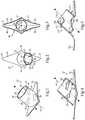
Figure 1 is a perspective view of a device, according to one embodiment;Figure 2 is a top view of the device ofFigure 1 ;Figure 3 is a bottom view of the device ofFigures 1 and 2 ;Figure 4 is a partially sectioned side diagrammatic view of the device ofFigures 1-3 ;Figure 5 is a partially sectioned side diagrammatic view of a device according to another embodiment;Figure 6 is a diagrammatic view at one stage of a procedure, according to one embodiment;Figure 7 is a diagrammatic view at another stage of the procedure;Figure 8 is a diagrammatic view at yet another stage of the procedure;Figure 9 is a diagrammatic view at yet another stage of the procedure; andFigure 10 is a diagrammatic view at one stage of another procedure, according to one embodiment.- Referring to
Figure 1 , there is shown adevice 10 for forming a fistula between blood vessels in a patient.Device 10 includes atubular body 12 defining alongitudinal axis 14, and being positionable within an opening in the end of a first vessel.Tubular body 12 includes anouter surface 16, and aninner surface 18. Acentral lumen 20 extends between a firstaxial body end 22 and a secondaxial body end 24. Aflange 26 is attached totubular body 12 at secondaxial body end 24, and positionable within an opening in the side of a second vessel to be connected to the first vessel via the fistula.Flange 26 projects outwardly fromouter surface 16. At least onevane 28 is attached totubular body 12 and projects inwardly frominner surface 18 intolumen 20. Vane 28 has an axially and circumferentially advancing orientation so as to induce helical flow in blood passed throughcentral lumen 20 between the first and second vessels. In a practicalimplementation strategy flange 26 is circumferential oftubular body 12. In other embodiments,flange 26 might extend only part way abouttubular body 12, having a circumferential extent less than 360°.Device 10 may be formed as a one-piece, unitary injection molded part formed of a suitable biocompatible polymer material, but in other instances could be formed from two separately constructed pieces attached to one another by way of an adhesive or welding together of the pieces. As will be further apparent from the following description,device 10 provides an efficient mechanism for forming an arteriovenous or other fistula.Device 10 can, moreover, be expected to promote improved fistula patency through reduction in hyperplasia as a result of the induced helical flow as further discussed herein. - Referring also now to
Figures 2, 3 and 4 ,tubular body 12 may be cylindrical, andflange 26 may project outwardly in directions oriented diagonally tolongitudinal axis 14.Flange 26 may be elongated so as to define aminor diameter 17 and amajor diameter 15.Major diameter 15 may be oriented diagonally tolongitudinal axis 14. As can be seen fromFigure 3 ,minor diameter 17 andmajor diameter 15 are in the plane of the page in that illustration, andaxis 14 will be understood to extend in and out of the page but at an angle corresponding generally to an orientation oftubular body 12. As can further be seen fromFigure 3 , in the illustrated embodimentmajor diameter 15 andminor diameter 17 are oriented normal to one another and intersect one another andlongitudinal axis 14 at a common point.Minor diameter 17 is oriented normal toaxis 14. The diagonal orientation oftubular body 12relative flange 26 can assist in forming a fistula inasmuch as bending and/or turning the attached vessels may be less than would be required with a design where a tubular body and flange are orthogonal to one another. An included angle betweenaxis 14 andmajor diameter 15 might be from about 20 degrees to about 70 degrees, although the present disclosure is not thereby limited. - From
Figure 2 it can be seen thatflange 26 has an upper side 54 oriented towardtubular body 12, and shown inFigure 3 is a lower side 6 that faces away fromtubular body 12. In a practical implementation strategy, upper side 54 may include a convex side, and lower side 56 may include a concave side.Flange 26 further includes a plurality ofedges sharp corners blunt corners device 10 will typically be sharp in the sense of capable of readily slicing blood vessel tissue.Blunt corners device 10 into a slit opening in a vessel, as further discussed herein, whereascorners device 10 by way of impinging upon inner vessel walls of a bloodvessel receiving flange 26. The concave and convex shapes of surfaces 54 and 56 will assist in substantially matching a shape offlange 26 to the vessel lumen whereinflange 26 is to be implanted. In other embodiments,flange 26 might have the shape of an ellipse, or still another geometry such as ovoid, circular, or irregular. - As noted above,
device 10 includes at least onevane 28, shown in phantom inFigure 1 . In a practical implementation strategy, the at least onevane 28 circumferentially advances at least one complete turn aboutaxis 14. In a further practical implementation strategy, the at least onevane 28 includes a plurality ofvanes vane 28 projects inwardly frominner surface 18 intocentral lumen 20.Inner surface 18 may have a cylindrical shape, and an extent of inward projection ofvanes inner surface 18 toaxis 14. Another way to understand this feature, as best shown inFigure 4 , is that a radial extent 58 of each of the vanes frominner surface 18 in a straight line towardaxis 14 is from about 1/3 to about 2/3 of the total distance frominner surface 18 toaxis 14. Acircumferential extent 60 of each ofvanes axis 14 may be such that a total or sum circumferential extent of all the vanes, as noted above, is equal to at least one full turn, or 360°, aboutlongitudinal axis 14. In certain instances, it might be desirable to have a greater sum circumferential extent, or a lesser sum circumferential extent of the plurality of vanes. - It will regardless typically be desirable to impart circumferential velocity components to blood passing between an
opening 38 in firstaxial end 22 and anopening 39 in secondaxial end 34, within a relatively short axial distance. In other words, since it is generally desirable to avoid substantially obstructing flow or occluding the available flow area for blood, it will tend to be desirable to impart the helical flow relatively aggressively, and without utilizing vanes that extend a full axial length oftubular body 12 betweenopenings Figure 2 ,vane 28 is shown having aninner vane edge 31, and anouter vane edge 29 adjoininginner surface 18.Vane 30 is shown having a leadingedge 34, which will typically be directed in an upstream direction respecting blood flow throughdevice 10, and a trailing edge 36.Edges 34 and 36 might be shaped, such as being rounded, to impart desirable flow characteristics to blood, such as reducing turbulence. Orientations ofedges 34 and 36 may be substantially perpendicular toinner surface 18. In certain embodiments, an unobstructed line of sight parallel toaxis 15 extends throughcentral lumen 20 between a leading edge and a trailing edge of an adjacent pair of the plurality of vanes. FromFigure 4 it can be readily seen that an unobstructed line of sight would extend betweenvanes Vane 32 inFigure 4 will be understood to be above the plane of the page, and thus not visible in the sectioned view. Alternative embodiments are contemplated, however, where the vanes have an overlapping configuration, so that no unobstructed line of site could be found between leading and trailing vane edges in the manner described. - Referring now to
Figure 5 , there is shown adevice 110 having certain similarities withdevice 10 described above, but certain differences.Device 110 includes atubular body 112 and an attachedflange 126, wheretubular body 112 defines alongitudinal axis 114. Rather than a plurality of vanes, asingle vane 128 is provided, and advances axially and circumferentially throughtubular body 112, with the extent of axial advancement being a majority of an axial length oftubular body 112, and an extent of the circumferential advancement being greater than 360°, in the illustrated example about 1 1/4 turns aboutaxis 114.Device 110 also includes avessel retention feature 113 in the nature of abarb 113 circumferential oftubular body 112, and projecting radially outward. Those skilled in the art will appreciate analogy between the shape ofbarb 113 and features known from the field of connecting valve fittings to tubes. As a blood vessel to be joined to another viadevice 110 is slid overtubular body 112, after passing overbarb 113, retention of the blood vessel in place will generally be enhanced by gripping ofbarb 113.Barb 113 is one example of a number of different features that might be used for retention of a blood vessel abouttubular body 112. "Barb" 113 might instead be a plurality of barbs, non-circumferential barbs, or still another geometric contrivance for mechanical retention such as a plurality of spicules. In still other instances, one or more through-holes might extend throughtubular body 112, ortubular body 12 by way of analogy, to enable sutures to be passed through a blood vessel and also throughdevice 10 to secure the two together. A small hole throughtubular body 112 in a generally radial direction can be readily visualized for such purposes. In still other instances, a clamp or some other external mechanism might be used, and a practical implementation strategy further discussed below includes a resilient loop such as a medical grade rubber band held in tension and positioned upontubular body 12, such that the resilient loop can be rolled over the vessel receivingtubular body - In view of the foregoing, it will be readily understood that a variety of different geometries are contemplated herein respecting
tubular body vane flange devices vanes vane 128, in other embodiments the pitch of one or more vanes could vary within the corresponding tubular body. The vanes illustrated herein also have a generally consistent extent of radial projection, in other words radial width. In other embodiments, vanes could have a tapered radial extent, starting at about zero toward one axial end of the corresponding tubular body, increasing as the vane extends in an axial direction, and then decreasing once again as the vane approaches its end. Still further variations will be readily apparent to those skilled in the art. - Referring now to the drawings generally, but in particular to
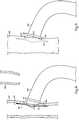
Figure 6 , there is shown afirst vessel 300 having been severed, such as by a physician with a surgical cutting tool, rendering anopening 304 in the end thereof.Device 10 is shown in the process of slidingend 22 oftubular body 12 intoopening 304 so as to fluidly connectfirst vessel 300, and in particular avessel lumen 302, withlumen 20 intubular body 12. The present description of the use ofdevice 10 will be understood to refer analogously todevice 110. Also shown inFigure 6 is aresilient band 62 held in tension upontubular body 12. The arrow upontubular body 12 indicates an approximate direction of sliding relative tovessel 300. Also shown inFigure 6 is asecond vessel 200 having anopening 204 such as a slit formed in a side thereof. - Referring now to
Figure 7 , there is showndevice 10 more fully positioned withinvessel 300, and whereresilient band 62 has been rolled or slid overvessel 300 to retaindevice 10 withinvessel 300. Referring also toFigure 8 , there is showndevice 10 connected tovessel 300 whereflange 26, attached tosecond end 24 has been slid intoopening 204 so as to fluidly connectsecond vessel 200 withlumen 20 indevice 10. After completely slidingflange 26 intovessel 200, blood flow communication betweenvessel 300 andvessel 200 may be established via the fluid connections ofvessels lumen 20. Blood flow communication may be controlled via a clamp or the like aboutvessel 200 in a conventional manner. It can be seen from the drawings that flange 26 may be elongated, and also that a length offlange 26 may be greater than a length ofopening 204. Accordingly, insertingflange 26 intoopening 204 may involve deforming tissue ofvessel 200 at least modestly and enteringflange 26 at an angle. Sliding offlange 26 intovessel 200 in this manner might be facilitated by slipping one ofcorners opening 204 first, and following with the rest offlange 26 and part oftubular body 12. It will be appreciated thatmajor diameter 15 offlange 26 may be aligned withopening 204, in other words the slit, during the insertion offlange 26. - Referring also now to
Figure 9 , there is showndevice 10 andvessels sutures 400 are shown on opposite sides ofdevice 10 andvessel 300, which may project slightly intovessel 200, withsutures 400 securing the vessels and device together. In a practical implementation strategy,vessel 300 is a vein, such thatopening 304 is formed in a cut end of the vein.Vessel 200 is an artery such thatopening 204 is formed in the side ofartery 200. With blood flow communication established between first andsecond vessels lumen 20 may be induced viavanes - Referring now to
Figure 10 , it will be recalled that a practical application of fistula formation is in facilitating hemodialysis. InFigure 10 , adialysis mechanism 500 is shown coupled with acatheter mechanism 502 that has been positioned withinvessel 300 to both receive and return blood for conventional dialysis treatment.Catheter mechanism 502 is illustrated as having both an outflow lumen/port and an inflow lumen/port within the same device body. In other instances separate withdrawal and return needles or the like can be used. Also shown inFigure 10 are arrows illustrating approximate blood flow directions as they might appear where helical flow is induced viavanes device 10. It should be appreciated that the term helical flow is a descriptive term meaning at least some of the blood in any given section of a blood vessel is traveling in a helical pattern, not necessarily that all of the blood is traveling in a helical pattern. It is in fact likely that a relatively modest extent of helical flow at or close to an inner vessel wall is likely all that is needed to glean the benefits contemplated herein. Circumferential flow components aboutaxis 306 ofvessel lumen 302 are seen some distance downstream ofdevice 10. It has been discovered that helical outflow may persist at least several device lengths downstream, potentially several centimeters, and is considered to provide advantages over known fistula devices that do not induce such flow, promoting long-term fistula patency. With at least some circumferential velocity components to the blood flow, in other words some helical flow, the pattern of blood flow communication betweenvessels - The present description is for illustrative purposes only, and should not be construed to narrow the breadth of the present disclosure in any way. Thus, those skilled in the art will appreciate that various modifications might be made to the presently disclosed embodiments without departing from the full and fair scope of the appended claims. Other aspects, features and advantages will be apparent upon an examination of the attached drawings and appended claims.
Claims (13)
- A device (10, 110) for forming a fistula between blood vessels in a patient comprising:a tubular body (12, 112) defining a longitudinal axis (14, 114) and being positionable within an opening in the end of a first vessel, and the tubular body including an outer surface (16), an inner surface (18), and a central lumen (20) extending between a first axial end (22) and a second axial end (24); anda flange (26, 126) positionable within an opening in the side of a second vessel to be connected to the first vessel via the fistula, and the flange being attached to the tubular body (12, 112) at the second axial end (24) and projecting outwardly from the outer surface (16);characterised by at least one vane (28, 128) attached to the tubular body (12, 112) and projecting inwardly from the inner surface (18) into the lumen (20), and the at least one vane (28, 128) having an axially and circumferentially advancing orientation so as to induce helical flow in blood passed through the lumen (20) between the first and second vessels.
- The device of claim 1 wherein the flange is circumferential of the tubular body.
- The device of claim 1 wherein the tubular body is cylindrical and the flange projects outwardly in directions oriented diagonally to the longitudinal axis.
- The device of any one of the preceding claims wherein the flange is elongated so as to define a minor diameter (17) and a major diameter (15), and the major diameter is oriented diagonally to the longitudinal axis.
- The device of claim 4 wherein the major diameter and the minor diameter are oriented normal to one another and intersect one another and the longitudinal axis at a common point, and wherein the minor diameter is oriented normal to the longitudinal axis.
- The device of any one of the preceding claims wherein the flange has a convex side, and an opposite concave side facing away from the tubular body.
- The device of claim 6 wherein the flange includes a plurality of edges (40,42,44,45), and a plurality of corners (46,48,50,52) formed at junctions of the plurality of edges.
- The device of claim 7 wherein the plurality of corners includes two sharp corners (46,48) and two blunt corners (50,52).
- The device of any one of the preceding claims wherein the at least one vane circumferentially advances at least one complete turn about the longitudinal axis.
- The device of any one of the preceding claims wherein the at least one vane includes a plurality of vanes.
- The device of claim 10 wherein the inner surface has a cylindrical shape, and wherein an extent of inward projection of the plurality of vanes is from about one-third to about two-thirds a radial distance from the inner surface to the longitudinal axis.
- The device of any one of the preceding claims wherein an unobstructed line of sight extends through the lumen between a leading edge and a trailing edge of an adjacent pair of the plurality of vanes.
- The device of any one of the preceding claims further comprising a resilient loop (62) held in tension and positioned upon the tubular body.
Applications Claiming Priority (1)
| Application Number | Priority Date | Filing Date | Title |
|---|---|---|---|
| US201462008818P | 2014-06-06 | 2014-06-06 |
Publications (2)
| Publication Number | Publication Date |
|---|---|
| EP2952142A1 EP2952142A1 (en) | 2015-12-09 |
| EP2952142B1true EP2952142B1 (en) | 2017-09-06 |
Family
ID=52780805
Family Applications (1)
| Application Number | Title | Priority Date | Filing Date |
|---|---|---|---|
| EP15159244.1AActiveEP2952142B1 (en) | 2014-06-06 | 2015-03-16 | Device for forming fistula between blood vessels |
Country Status (2)
| Country | Link |
|---|---|
| US (1) | US10420873B2 (en) |
| EP (1) | EP2952142B1 (en) |
Families Citing this family (5)
| Publication number | Priority date | Publication date | Assignee | Title |
|---|---|---|---|---|
| US9463269B2 (en) | 2010-09-10 | 2016-10-11 | W. L. Gore & Associates, Inc. | Anastomotic devices and methods |
| US10849627B2 (en)* | 2015-08-28 | 2020-12-01 | University Of Cincinnati | Arteriovenous fistula implant effective for inducing laminar blood flow |
| GB2577940A (en)* | 2018-10-12 | 2020-04-15 | Spectrum Medical Ltd | Seal |
| CN111419493B (en)* | 2020-03-24 | 2021-08-13 | 西安交通大学医学院第一附属医院 | A medical intravascular implant device |
| WO2022005909A2 (en)* | 2020-06-30 | 2022-01-06 | Nxt Biomedical, Llc | Rivet docking platform, occluder |
Citations (1)
| Publication number | Priority date | Publication date | Assignee | Title |
|---|---|---|---|---|
| US20120123520A1 (en)* | 1998-12-28 | 2012-05-17 | Tayside University Hospitals Nhs Trust | Blood-flow tubing |
Family Cites Families (11)
| Publication number | Priority date | Publication date | Assignee | Title |
|---|---|---|---|---|
| US5344425A (en) | 1990-09-14 | 1994-09-06 | Interface Biomedical Laboratories, Corp. | Intravascular stent and method for conditioning the surfaces thereof |
| CA2244080A1 (en) | 1996-02-02 | 1997-08-07 | Transvascular, Inc. | Methods and apparatus for blocking flow through blood vessels |
| US6019788A (en)* | 1996-11-08 | 2000-02-01 | Gore Enterprise Holdings, Inc. | Vascular shunt graft and junction for same |
| GB9706965D0 (en) | 1997-04-05 | 1997-05-21 | Univ Belfast | Haemodynamic control deviceo |
| EP1072282A1 (en) | 1999-07-19 | 2001-01-31 | EndoArt S.A. | Flow control device |
| GB2384189A (en) | 2001-11-21 | 2003-07-23 | Tayside Flow Technologies Ltd | Helix shaped insert for flow moification in a duct or stent |
| US7828814B2 (en) | 2004-08-27 | 2010-11-09 | Rox Medical, Inc. | Device and method for establishing an artificial arterio-venous fistula |
| EP1912592A4 (en) | 2005-07-26 | 2016-01-06 | Rox Medical Inc | DEVICES, SYSTEMS AND METHODS FOR ARTERIOVINOUS FISTULA CREATION |
| EP2173259A4 (en)* | 2007-08-02 | 2015-07-08 | Bio Connect Systems | Implantable flow connector |
| US9616214B2 (en)* | 2012-05-21 | 2017-04-11 | Becton, Dickinson And Company | Flush enhancing male luer tip design for syringes and any luer connector |
| CA3113910C (en)* | 2012-08-10 | 2023-09-19 | Abiomed, Inc. | Graft anchor devices, systems, and methods |
- 2015
- 2015-03-16EPEP15159244.1Apatent/EP2952142B1/enactiveActive
- 2015-03-25USUS14/668,049patent/US10420873B2/enactiveActive
Patent Citations (1)
| Publication number | Priority date | Publication date | Assignee | Title |
|---|---|---|---|---|
| US20120123520A1 (en)* | 1998-12-28 | 2012-05-17 | Tayside University Hospitals Nhs Trust | Blood-flow tubing |
Also Published As
| Publication number | Publication date |
|---|---|
| EP2952142A1 (en) | 2015-12-09 |
| US10420873B2 (en) | 2019-09-24 |
| US20150352273A1 (en) | 2015-12-10 |
Similar Documents
| Publication | Publication Date | Title |
|---|---|---|
| EP2952142B1 (en) | Device for forming fistula between blood vessels | |
| US11504461B2 (en) | Arteriovenous graft for hemodialysis with puncture-resistant posterior and side walls | |
| US11185676B2 (en) | Vascular access system with connector | |
| JP5873057B2 (en) | Symmetrical tip sharp catheter | |
| EP3033122B1 (en) | Systems for a fluid carrying conduit of a vascular access system | |
| CN107913445A (en) | Conduit with asymmetric end | |
| US10034739B2 (en) | Stent to assist in arteriovenous fistula formation | |
| US20130274648A1 (en) | Blood flow controllers and methods | |
| US20180078697A1 (en) | Vascular access system with connector | |
| JP2021192819A (en) | Hemodialysis catheter having waveform tip | |
| US20120071965A1 (en) | Implantable graft connector | |
| EP2432521A1 (en) | A vascular graft | |
| US10850084B1 (en) | Arteriovenous graft and method of providing dialysis | |
| EP4321186B1 (en) | Devices for fistula-free hemodialysis | |
| US9561320B2 (en) | Device for promoting fistula patency and method | |
| EP3103418B1 (en) | Spiral blood flow device with diameter independent helix angle | |
| US20160199065A1 (en) | Extravascular device for limiting blood flow adjacent an arteriovenous fistula | |
| EP3207902A1 (en) | Spiral flow inducing stent and cannula cut method of making same | |
| US9687240B2 (en) | Implant for facilitating sutureless side-to-side arteriovenous fistula creation and maintaining patency | |
| WO2024218211A1 (en) | An improved hemodialysis device | |
| US20200016367A1 (en) | Self-Centric Symmetric Catheter |
Legal Events
| Date | Code | Title | Description |
|---|---|---|---|
| PUAI | Public reference made under article 153(3) epc to a published international application that has entered the european phase | Free format text:ORIGINAL CODE: 0009012 | |
| AK | Designated contracting states | Kind code of ref document:A1 Designated state(s):AL AT BE BG CH CY CZ DE DK EE ES FI FR GB GR HR HU IE IS IT LI LT LU LV MC MK MT NL NO PL PT RO RS SE SI SK SM TR | |
| AX | Request for extension of the european patent | Extension state:BA ME | |
| 17P | Request for examination filed | Effective date:20160113 | |
| RBV | Designated contracting states (corrected) | Designated state(s):AL AT BE BG CH CY CZ DE DK EE ES FI FR GB GR HR HU IE IS IT LI LT LU LV MC MK MT NL NO PL PT RO RS SE SI SK SM TR | |
| 17Q | First examination report despatched | Effective date:20160317 | |
| GRAP | Despatch of communication of intention to grant a patent | Free format text:ORIGINAL CODE: EPIDOSNIGR1 | |
| INTG | Intention to grant announced | Effective date:20170328 | |
| RIN1 | Information on inventor provided before grant (corrected) | Inventor name:SHIELDS, ADAM Inventor name:MILNER, KEITH | |
| GRAS | Grant fee paid | Free format text:ORIGINAL CODE: EPIDOSNIGR3 | |
| GRAA | (expected) grant | Free format text:ORIGINAL CODE: 0009210 | |
| AK | Designated contracting states | Kind code of ref document:B1 Designated state(s):AL AT BE BG CH CY CZ DE DK EE ES FI FR GB GR HR HU IE IS IT LI LT LU LV MC MK MT NL NO PL PT RO RS SE SI SK SM TR | |
| REG | Reference to a national code | Ref country code:GB Ref legal event code:FG4D | |
| REG | Reference to a national code | Ref country code:CH Ref legal event code:EP Ref country code:AT Ref legal event code:REF Ref document number:925008 Country of ref document:AT Kind code of ref document:T Effective date:20170915 | |
| REG | Reference to a national code | Ref country code:IE Ref legal event code:FG4D | |
| REG | Reference to a national code | Ref country code:DE Ref legal event code:R096 Ref document number:602015004518 Country of ref document:DE | |
| REG | Reference to a national code | Ref country code:NL Ref legal event code:MP Effective date:20170906 | |
| REG | Reference to a national code | Ref country code:LT Ref legal event code:MG4D | |
| PG25 | Lapsed in a contracting state [announced via postgrant information from national office to epo] | Ref country code:LT Free format text:LAPSE BECAUSE OF FAILURE TO SUBMIT A TRANSLATION OF THE DESCRIPTION OR TO PAY THE FEE WITHIN THE PRESCRIBED TIME-LIMIT Effective date:20170906 Ref country code:SE Free format text:LAPSE BECAUSE OF FAILURE TO SUBMIT A TRANSLATION OF THE DESCRIPTION OR TO PAY THE FEE WITHIN THE PRESCRIBED TIME-LIMIT Effective date:20170906 Ref country code:NO Free format text:LAPSE BECAUSE OF FAILURE TO SUBMIT A TRANSLATION OF THE DESCRIPTION OR TO PAY THE FEE WITHIN THE PRESCRIBED TIME-LIMIT Effective date:20171206 Ref country code:FI Free format text:LAPSE BECAUSE OF FAILURE TO SUBMIT A TRANSLATION OF THE DESCRIPTION OR TO PAY THE FEE WITHIN THE PRESCRIBED TIME-LIMIT Effective date:20170906 Ref country code:HR Free format text:LAPSE BECAUSE OF FAILURE TO SUBMIT A TRANSLATION OF THE DESCRIPTION OR TO PAY THE FEE WITHIN THE PRESCRIBED TIME-LIMIT Effective date:20170906 | |
| REG | Reference to a national code | Ref country code:AT Ref legal event code:MK05 Ref document number:925008 Country of ref document:AT Kind code of ref document:T Effective date:20170906 | |
| PG25 | Lapsed in a contracting state [announced via postgrant information from national office to epo] | Ref country code:BG Free format text:LAPSE BECAUSE OF FAILURE TO SUBMIT A TRANSLATION OF THE DESCRIPTION OR TO PAY THE FEE WITHIN THE PRESCRIBED TIME-LIMIT Effective date:20171206 Ref country code:LV Free format text:LAPSE BECAUSE OF FAILURE TO SUBMIT A TRANSLATION OF THE DESCRIPTION OR TO PAY THE FEE WITHIN THE PRESCRIBED TIME-LIMIT Effective date:20170906 Ref country code:ES Free format text:LAPSE BECAUSE OF FAILURE TO SUBMIT A TRANSLATION OF THE DESCRIPTION OR TO PAY THE FEE WITHIN THE PRESCRIBED TIME-LIMIT Effective date:20170906 Ref country code:GR Free format text:LAPSE BECAUSE OF FAILURE TO SUBMIT A TRANSLATION OF THE DESCRIPTION OR TO PAY THE FEE WITHIN THE PRESCRIBED TIME-LIMIT Effective date:20171207 Ref country code:RS Free format text:LAPSE BECAUSE OF FAILURE TO SUBMIT A TRANSLATION OF THE DESCRIPTION OR TO PAY THE FEE WITHIN THE PRESCRIBED TIME-LIMIT Effective date:20170906 | |
| PG25 | Lapsed in a contracting state [announced via postgrant information from national office to epo] | Ref country code:NL Free format text:LAPSE BECAUSE OF FAILURE TO SUBMIT A TRANSLATION OF THE DESCRIPTION OR TO PAY THE FEE WITHIN THE PRESCRIBED TIME-LIMIT Effective date:20170906 | |
| PG25 | Lapsed in a contracting state [announced via postgrant information from national office to epo] | Ref country code:CZ Free format text:LAPSE BECAUSE OF FAILURE TO SUBMIT A TRANSLATION OF THE DESCRIPTION OR TO PAY THE FEE WITHIN THE PRESCRIBED TIME-LIMIT Effective date:20170906 Ref country code:RO Free format text:LAPSE BECAUSE OF FAILURE TO SUBMIT A TRANSLATION OF THE DESCRIPTION OR TO PAY THE FEE WITHIN THE PRESCRIBED TIME-LIMIT Effective date:20170906 Ref country code:PL Free format text:LAPSE BECAUSE OF FAILURE TO SUBMIT A TRANSLATION OF THE DESCRIPTION OR TO PAY THE FEE WITHIN THE PRESCRIBED TIME-LIMIT Effective date:20170906 | |
| PG25 | Lapsed in a contracting state [announced via postgrant information from national office to epo] | Ref country code:SM Free format text:LAPSE BECAUSE OF FAILURE TO SUBMIT A TRANSLATION OF THE DESCRIPTION OR TO PAY THE FEE WITHIN THE PRESCRIBED TIME-LIMIT Effective date:20170906 Ref country code:SK Free format text:LAPSE BECAUSE OF FAILURE TO SUBMIT A TRANSLATION OF THE DESCRIPTION OR TO PAY THE FEE WITHIN THE PRESCRIBED TIME-LIMIT Effective date:20170906 Ref country code:IS Free format text:LAPSE BECAUSE OF FAILURE TO SUBMIT A TRANSLATION OF THE DESCRIPTION OR TO PAY THE FEE WITHIN THE PRESCRIBED TIME-LIMIT Effective date:20180106 Ref country code:IT Free format text:LAPSE BECAUSE OF FAILURE TO SUBMIT A TRANSLATION OF THE DESCRIPTION OR TO PAY THE FEE WITHIN THE PRESCRIBED TIME-LIMIT Effective date:20170906 Ref country code:AT Free format text:LAPSE BECAUSE OF FAILURE TO SUBMIT A TRANSLATION OF THE DESCRIPTION OR TO PAY THE FEE WITHIN THE PRESCRIBED TIME-LIMIT Effective date:20170906 Ref country code:EE Free format text:LAPSE BECAUSE OF FAILURE TO SUBMIT A TRANSLATION OF THE DESCRIPTION OR TO PAY THE FEE WITHIN THE PRESCRIBED TIME-LIMIT Effective date:20170906 | |
| REG | Reference to a national code | Ref country code:DE Ref legal event code:R097 Ref document number:602015004518 Country of ref document:DE | |
| PLBE | No opposition filed within time limit | Free format text:ORIGINAL CODE: 0009261 | |
| STAA | Information on the status of an ep patent application or granted ep patent | Free format text:STATUS: NO OPPOSITION FILED WITHIN TIME LIMIT | |
| PG25 | Lapsed in a contracting state [announced via postgrant information from national office to epo] | Ref country code:DK Free format text:LAPSE BECAUSE OF FAILURE TO SUBMIT A TRANSLATION OF THE DESCRIPTION OR TO PAY THE FEE WITHIN THE PRESCRIBED TIME-LIMIT Effective date:20170906 | |
| 26N | No opposition filed | Effective date:20180607 | |
| PG25 | Lapsed in a contracting state [announced via postgrant information from national office to epo] | Ref country code:SI Free format text:LAPSE BECAUSE OF FAILURE TO SUBMIT A TRANSLATION OF THE DESCRIPTION OR TO PAY THE FEE WITHIN THE PRESCRIBED TIME-LIMIT Effective date:20170906 | |
| REG | Reference to a national code | Ref country code:CH Ref legal event code:PL | |
| PG25 | Lapsed in a contracting state [announced via postgrant information from national office to epo] | Ref country code:MC Free format text:LAPSE BECAUSE OF FAILURE TO SUBMIT A TRANSLATION OF THE DESCRIPTION OR TO PAY THE FEE WITHIN THE PRESCRIBED TIME-LIMIT Effective date:20170906 | |
| REG | Reference to a national code | Ref country code:BE Ref legal event code:MM Effective date:20180331 | |
| PG25 | Lapsed in a contracting state [announced via postgrant information from national office to epo] | Ref country code:LU Free format text:LAPSE BECAUSE OF NON-PAYMENT OF DUE FEES Effective date:20180316 | |
| PG25 | Lapsed in a contracting state [announced via postgrant information from national office to epo] | Ref country code:BE Free format text:LAPSE BECAUSE OF NON-PAYMENT OF DUE FEES Effective date:20180331 Ref country code:LI Free format text:LAPSE BECAUSE OF NON-PAYMENT OF DUE FEES Effective date:20180331 Ref country code:CH Free format text:LAPSE BECAUSE OF NON-PAYMENT OF DUE FEES Effective date:20180331 | |
| PG25 | Lapsed in a contracting state [announced via postgrant information from national office to epo] | Ref country code:FR Free format text:LAPSE BECAUSE OF NON-PAYMENT OF DUE FEES Effective date:20180331 | |
| PG25 | Lapsed in a contracting state [announced via postgrant information from national office to epo] | Ref country code:MT Free format text:LAPSE BECAUSE OF NON-PAYMENT OF DUE FEES Effective date:20180316 | |
| PG25 | Lapsed in a contracting state [announced via postgrant information from national office to epo] | Ref country code:TR Free format text:LAPSE BECAUSE OF FAILURE TO SUBMIT A TRANSLATION OF THE DESCRIPTION OR TO PAY THE FEE WITHIN THE PRESCRIBED TIME-LIMIT Effective date:20170906 | |
| PG25 | Lapsed in a contracting state [announced via postgrant information from national office to epo] | Ref country code:PT Free format text:LAPSE BECAUSE OF FAILURE TO SUBMIT A TRANSLATION OF THE DESCRIPTION OR TO PAY THE FEE WITHIN THE PRESCRIBED TIME-LIMIT Effective date:20170906 | |
| PG25 | Lapsed in a contracting state [announced via postgrant information from national office to epo] | Ref country code:MK Free format text:LAPSE BECAUSE OF NON-PAYMENT OF DUE FEES Effective date:20170906 Ref country code:CY Free format text:LAPSE BECAUSE OF FAILURE TO SUBMIT A TRANSLATION OF THE DESCRIPTION OR TO PAY THE FEE WITHIN THE PRESCRIBED TIME-LIMIT Effective date:20170906 Ref country code:HU Free format text:LAPSE BECAUSE OF FAILURE TO SUBMIT A TRANSLATION OF THE DESCRIPTION OR TO PAY THE FEE WITHIN THE PRESCRIBED TIME-LIMIT; INVALID AB INITIO Effective date:20150316 | |
| PG25 | Lapsed in a contracting state [announced via postgrant information from national office to epo] | Ref country code:AL Free format text:LAPSE BECAUSE OF FAILURE TO SUBMIT A TRANSLATION OF THE DESCRIPTION OR TO PAY THE FEE WITHIN THE PRESCRIBED TIME-LIMIT Effective date:20170906 | |
| P01 | Opt-out of the competence of the unified patent court (upc) registered | Effective date:20230602 | |
| PGFP | Annual fee paid to national office [announced via postgrant information from national office to epo] | Ref country code:DE Payment date:20250327 Year of fee payment:11 | |
| PGFP | Annual fee paid to national office [announced via postgrant information from national office to epo] | Ref country code:IE Payment date:20250318 Year of fee payment:11 | |
| PGFP | Annual fee paid to national office [announced via postgrant information from national office to epo] | Ref country code:GB Payment date:20250326 Year of fee payment:11 |