EP2949355B1 - Hinged cap for needle device - Google Patents
Hinged cap for needle deviceDownload PDFInfo
- Publication number
- EP2949355B1 EP2949355B1EP15170053.1AEP15170053AEP2949355B1EP 2949355 B1EP2949355 B1EP 2949355B1EP 15170053 AEP15170053 AEP 15170053AEP 2949355 B1EP2949355 B1EP 2949355B1
- Authority
- EP
- European Patent Office
- Prior art keywords
- cap
- needle
- hinged
- base
- hook arm
- Prior art date
- Legal status (The legal status is an assumption and is not a legal conclusion. Google has not performed a legal analysis and makes no representation as to the accuracy of the status listed.)
- Active
Links
Images


Classifications
- A—HUMAN NECESSITIES
- A61—MEDICAL OR VETERINARY SCIENCE; HYGIENE
- A61M—DEVICES FOR INTRODUCING MEDIA INTO, OR ONTO, THE BODY; DEVICES FOR TRANSDUCING BODY MEDIA OR FOR TAKING MEDIA FROM THE BODY; DEVICES FOR PRODUCING OR ENDING SLEEP OR STUPOR
- A61M5/00—Devices for bringing media into the body in a subcutaneous, intra-vascular or intramuscular way; Accessories therefor, e.g. filling or cleaning devices, arm-rests
- A61M5/178—Syringes
- A61M5/31—Details
- A61M5/32—Needles; Details of needles pertaining to their connection with syringe or hub; Accessories for bringing the needle into, or holding the needle on, the body; Devices for protection of needles
- A61M5/3205—Apparatus for removing or disposing of used needles or syringes, e.g. containers; Means for protection against accidental injuries from used needles
- A61M5/321—Means for protection against accidental injuries by used needles
- A61M5/3216—Caps placed transversally onto the needle, e.g. pivotally attached to the needle base
- A61M2005/3217—Means to impede repositioning of protection cap from needle covering to needle uncovering position, e.g. catch mechanisms
- A—HUMAN NECESSITIES
- A61—MEDICAL OR VETERINARY SCIENCE; HYGIENE
- A61M—DEVICES FOR INTRODUCING MEDIA INTO, OR ONTO, THE BODY; DEVICES FOR TRANSDUCING BODY MEDIA OR FOR TAKING MEDIA FROM THE BODY; DEVICES FOR PRODUCING OR ENDING SLEEP OR STUPOR
- A61M5/00—Devices for bringing media into the body in a subcutaneous, intra-vascular or intramuscular way; Accessories therefor, e.g. filling or cleaning devices, arm-rests
- A61M5/50—Devices for bringing media into the body in a subcutaneous, intra-vascular or intramuscular way; Accessories therefor, e.g. filling or cleaning devices, arm-rests having means for preventing re-use, or for indicating if defective, used, tampered with or unsterile
Definitions
- the present inventionrelates generally to caps for a needle device, and more particularly, to hinged cap devices for use with hypodermic needles as defined in claim 1.
- Recappingis a common procedure for periods between drawing up fluids into a syringe and administering injections through a needle.
- the recapping procedurecan occasionally cause needle sticks since users sometime misalign the needles with the openings on the caps, producing minimal pain but causing a great deal of inconvenience because all such needle stick incidences must be reported.
- needles related to the needle stick incidencesmust be discarded, medications contained within the syringes are unnecessarily wasted.
- fluids linked to these "clean" type of needle stickscan cause injuries and adverse reactions.
- Hinged cap devices of this kindare known in the state of the art.
- US 5,490,841discloses a needle protection device having an elongate housing with a longitudinal needle entrance portion defined between two housing side walls. At least one hinged door member is provided extending across the entrance portion to enclose the needle within the housing.
- US 4,976,699discloses a protective cover for a syringe needle which maintains the sterility of the needle prior to use, is easily displaced with one hand in order to employ the syringe in the application of fluid transfer via its needle portion with the same hand, is readily repositioned back over the needle with the same hand, prevents reuse, indicates prior use, prevents accidental needle sticks, and is able to be manufactured cost-effectively.
- hinged cap devicesare packaged ready for use without additional removable caps. However, in some cases, a removable cap may still be used as necessary or desired.
- a hinged safety cap devicehaving multiple positions will allow a user to safely cover a sharp needle tip during the periods between drawing up fluids and administering an injection to a patient.
- the needlecan be covered without locking the device to allow the needle to be exposed when necessary.
- he or shecan manipulate the hinged cap into a locked position so it can no longer be re-used or be exposed to cause needle stick injuries.
- an audible, visual and/or tactile signal(s)is provided to the user as an indication that the cap is securely locked over the needle.
- a hinged cap device for use with a syringeincludes a base defining an interior cavity for mounting onto a tip and a cap connected to the base by a living hinge.
- the capis moveable from a ready position to an open position to expose a needle, and from the open position to a secured position to prevent relative rotation between the cap and the base.
- a first latching mechanismis on the cap for engaging the needle, the first latching mechanism locatable on a first side of the needle in the ready position and locatable on a second side of the needle in the secured position.
- the needleis disengageable from the first latching mechanism in the ready position, and the needle is not disengageable from the first latching mechanism in the secured position.
- the hinged cap assemblymay optionally include a first latching mechanism having a projection attached to the cap and extending into the open channel and a catch lever straddling the projection to form an obtuse angle side and an acute angle side.
- the hinged cap devicemay also include a second latching mechanism on the cap for engaging at least one tab on the cap, the second latching mechanism dis-engageable from the at least one tab by axially moving the cap along a lengthwise axis of the needle relative to the hub.
- the second latching mechanismmay optionally include a pair of latch walls, one latch wall extending from the first side wall and the second side wall, wherein each latch wall comprises a notch adapted to engage a respective base tab on the base.
- the second latching mechanismmay include a pair of tabs, one lab extending from both the first side wall and the second side wall, wherein each tab is adapted to abut a respective base tab on the base.
- the hinged cap assemblymay further optionally include a base having a wedge and a cap having a pair of gripping plates, the wedge adapted to engage the gripping plates to temporarily maintain the cap in the open position.
- the hinged cap devicemay be a single integral device and the device may be injection molded.
- the hinged cap assemblymay also optionally include a first side wall having a notch having two end wall edges defining an angle therebetween. Additionally, a living hinge may be located on the cap spaced from the living hinge located between the cap and the base.
- Also provided is a method for operating a hinged cap deviceincluding moving a cap axially along a lengthwise direction of a needle to distort the living hinge to disengage the second latching mechanism from the base and rotating the cap radially outwardly relative to the needle from the ready position to the open position to expose the needle, and engaging the cap to the base in the cap open position.
- the methodmay also include rotating the cap radially inwardly relative to the needle to shield the needle from the open position to the secured position, thereby engaging the needle latching mechanism with the needle.
- the hinged cap assembly 10comprises a base or hub 12 for mounting onto a syringe tip (not shown), the base defining an interior cavity therein, and a cap 14 for shielding the needle 16 preceding or following an injection.
- the hinged cap assembly 10may be made by injection molding and, in one exemplary embodiment, is an integrally formed single unit in which the base 12 is connected to the cap 14 by a living hinge 18.
- the cap 14is rotatable with respect to the base 12 from a packaged or ready position ( FIG. 2 ) to an open position ( FIG. 1 ) and from the open position to a secured position ( FIG. 7 ).
- the base 12includes two integral cylinders 12a, 12b with the second cylinder 12b having a smaller diameter than the first cylinder.
- the first cylinder 12ais dimensioned to receive a syringe tip (not shown) of a syringe.
- the syringe tip and the hubmay engage one another using Luer tapers with the flange 13 located at a proximal end of the first cylinder 12a optionally engaging a threaded collar on the syringe to form a Luer lock, as is well known in the art.
- An integral coaxial cylindrical needle holder 17extends distally from the base 12 for securing a needle 16 to the base.
- the needle holder 17is dimensioned with a smaller diameter than the base and is adapted to be received by a hub alignment mechanism 36 when the hinged cap device 10 is in the ready position and in the secured position, as described in more detail below.
- a stopping edge 19is formed by a distal surface of the second cylinder 19b to limit axial movement of the base 12 with respect to the cap 14, as described in more detail below.
- the basemay incorporate a male projection for engaging a separate combination needle hub and needle.
- the alternative male projection(not shown) may be a male Luer taper having an optional Luer lock, which may be a collar having internal threads, as is well known in the art.
- a ridge or rib 15in incorporated on the second cylinder 12b and the needle holder 17 for reinforcement. In the example shown, two spaced apart ribs are incorporated, with only one shown.
- the cap 14generally is configured to shield and contain the needle 16 in the ready and secured positions to be easily manipulated between the ready and open positions; and to be easily manipulated between the open and secured positions.
- the cap 14comprises a base wall 28 and two side walls 20a, 20b, defining a generally U-shaped or otherwise open channel 22 therebetween.
- a profile of the cap 14includes a middle section 14b that extends deeper than a distal section 14a and a proximal section 14c.
- the base wall 28substantially follows the contour of the profile and serves to support various components of the cap, as described in more detail below.
- the side walls 20a, 20bextend upward from the base wall 28 and are generally parallel to each other in the proximal section 14c of the cap 14.
- the side walls 20a, 20bare configured to form a narrowingly tapered distally extending channel.
- An end wall 21extends between the two side walls 20a, 20b at a distal end of the cap 14.
- the side walls 20a, 20bmay extend generally parallel to one another along the entire length of the cap.
- the first latching mechanism 24comprises a cantilever projection 30 extending generally orthogonally of the base wall and a sloped catch lever 32 integral with a top surface of the projection.
- the projection 30is attached to a circumferential surface of an opening 23 in the base wall 28 located in the middle portion 14b of the cap 14 and extends into the channel 22. Since only a lower portion of the projection 30 is attached to the opening, the projection has lateral flexibility with respect to a longitudinal axis of the needle 16.
- the sloped catch lever 32straddles the projection 30, forming an obtuse angle with one side of the projection and an acute angle on the other side of the projection.
- the obtuse angle side of the sloped catch lever 32has a configuration such that when a bottom surface 60 ( FIG. 1 ) of the sloped catch lever encounters the needle 16 when the cap moves from a ready position to an open position, the first latch mechanism 24 is displaced and the catch lever can pass around the needle.
- the needle 16may deflect or bend slightly to pass around the obtuse angle side.
- the acute angle side of the sloped catch lever 32has a configuration such that when a top surface 58 of the catch lever encounters the needle 16 when the cap moves from an open position to the secured position, the first latch mechanism 24 is displaced and/or the needle is deflected and the needle can then pass around the catch lever.
- a userattempts to reposition the cap 14 into the open position from the secured position, and thereby pushes the bottom surface 60 of the acute angle side of the catch lever 32 against the needle, the needle cannot laterally displace the first latch mechanism 24 nor can the needle pass around the sloped catch lever, thereby maintaining the hinged cap device 10 in the secured position.
- the channel 22incorporates a first needle alignment mechanism 34 for aligning the needle 16 to the cap 14, the first needle alignment mechanism being located within the distal section 14a of the cap.
- the first needle alignment mechanism 34comprises a pair of aligned vertical walls 34a, 34b, one wall extending perpendicularly from each side wall 20a, 20b, having a gap therebetween adapted to receive the needle 16 and align it with a longitudinal axis of the cap 14.
- Each wall 34a, 34b of the first needle alignment mechanism 34includes a sloped leading edge 35 for directing the needle 16 into the gap between the walls when the cap is rotated from an open position to a secured position.
- the channel 22may incorporate a second needle alignment mechanism 50 having substantially the same structure as the first needle alignment mechanism in the middle section 14b, for example, and located distally adjacent the first latching mechanism 24.
- a hub alignment mechanism 36may be incorporated into the cap 14 for aligning the base 12 to the cap.
- the hub alignment mechanism 36includes two spaced walls 36a, 36b extending perpendicularly to side walls 20a, 20b, a forming a gap between each wall having a sloped leading edge 35.
- the gap between the walls 36a, 36bis dimensioned to receive the needle holder 17, and therefore is wider than the gap between walls of the first and second needle alignment mechanisms 34, 50, and is located proximal to the first catch mechanism.
- Each sidewall 20a, 20bcomprises an integral fin 39 extending proximally from about the hub alignment mechanism 36, the fins having a sloped top surface and a generally flat bottom surface.
- the fins 39includes an exterior indicia 41 ( FIG. 4 ), which may be, for example, a series of slightly raised protrusions, a roughened or corrugated surface, or a contoured surface.
- the exterior indicia 41adds to the aesthetic appeal of the cap.
- the capmay include lettering, symbols, or instructions.
- exterior indicia 41indicates to a user where to hold the cap 14 and also to allow the user to attain a more secure grip of the cap when moving the cap between the various positions.
- An integral ear, lever, or tab 40extends into the channel 22, the tabs being generally located toward a lower, proximal portion of each fin 39.
- the tabs 40are configured to abut corresponding tabs 38 extending from the base 12 to prevent relative movement between the cap 14 and the base in the ready position. More specifically, the tabs 38 extend from the second cylinder 12b and have a flat bottom surface adapted to abut a flat top surface of the tabs 40.
- the two sets of tabsprovide a temporary lock state and function as an added security feature when in the ready position.
- the base 12is connected to the cap 14 by a living hinge 18 located between a base segment 54 and a cap segment 56.
- the cap segment 56extends proximally from a proximal end of the base wall 28 and is generally parallel to a longitudinal axis of the cap 14.
- the base segment 54extends at an angle from a wall surface of the base 12 towards the cap segment 56 with the living hinge 18 integrally joined therebetween such that the living hinge not only allows rotation of the cap 14 relative to the base 12, but also allows for limited axial movement of the cap relative to the base to enable the tabs 38, 40 to be disengaged, as is described in more detail below.
- the cap 14comprises an integral push lever 48 extending from the base wall 28 away from the channel 22.
- a distally-facing surface 49 of the push lever 48is generally arc-shaped and dimensioned to generally conform to the side of a user's finger.
- the usercan use the push lever 48 to apply a compressive axial force toward a proximal end of the cap, and also apply a radial force to rotate the cap 14 with respect to the base 12.
- a push leversuch as an orthogonal lever, may be used within the scope of aspects of the present disclosure.
- a usermay simply grab the two side walls 20a, 20b to exert both an axial force and a radial force to open the cap. Still alternatively, a user can push the cap against a surface so that the end wall 21 of the cap ( FIG. 2 ) abuts the surface to create an axial force and a rotational force to open the cap.
- a wedge 42extends from a wall surface of the base 12, the wedge having a slightly arcuate configuration.
- the wedge 42is dimensioned to fit between two spaced gripping plates 44 which extend from the base wall 28 of the cap 14 ( FIG. 6 ). More specifically, the wedge 42 is located on the base 12 such that when the cap 14 is rotated by a certain amount about the living hinge 18 with respect to the base, the wedge engages the gripping plates 44 to temporarily retain the cap in the open position.
- the engagement between the wedge 42 and the gripping plates 44is a frictional engagement.
- toothed surfaces or detentsmay be used without deviating from scope of the present disclosure.
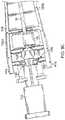
- the hinged cap assembly 10is shown in a packaged or ready position. As the name implies and although not shown, the assembly 10 may be packaged in the configuration shown inside a vacuum pack enclosure having a peelable cover configured for peeling to remove the assembly from the package.
- the needle 16is engaged on the obtuse angle side of the first latching mechanism 24 and extends through the first and second needle alignment members 34, 50.
- the cap 14is engaged to the base 12 via abutting surfaces of the tabs 38, 40, that prevent relative rotation between the base and the cap, and the needle holder 17 extends through the hub alignment mechanism 36.
- the tabs 40 on the capare disengaged from the tabs 38 on the base.
- the tabs 38, 40may be disengaged by pulling the cap 14 along a longitudinal axis of the needle 16 towards the base such that the surfaces of the tabs 38, 40 become entirely misaligned as shown in FIG. 3 .
- the axial movement of the cap 14 with respect to the base 12causes the living hinge 18 to curl or distort to accommodate for the axial movement of the cap, resulting in a portion of the cap segment 56 of the living hinge 18 moving proximally of a portion of the base segment 54 ( FIG. 4 ).
- the stopping edge 19abuts the walls 36a, 36b of the hub alignment mechanism, thereby limiting the amount of relative axial movement between the base 12 and the cap 14.
- the relative angle between the cap 14 and the needle 16indicates that the cap is rotating radially outwardly to free the needle from the obtuse side of the first latching mechanism 24.
- the needledisplaces the first latching mechanism 24 and/or the needle deflects to free the needle from the latching mechanism thus allowing the needle.
- the cap 14has been disengaged from the first latching mechanism 24, and the cap is rotated radially outwardly relative to the needle axis to further expose the needle 16. As shown in FIG.
- the wedge 42 on the baseengages the gripping plates 44 on the cap to temporarily retain the cap in the open position. In this position, an injection may be performed without the cap 14 interfering with the needle 16.
- the capis rotated radially inwardly relative to the needle axis such that the needle 16 encounters a top surface 58 of the catch lever 32 and laterally displaces the first latching mechanism 24, or alternatively or in addition thereto the needle deflects to allow the needle to pass around the first latching mechanism.
- the needle 16is secured beneath the catch lever and is prevented from laterally displacing the first latching mechanism 24 and/or from passing around the first latching mechanism regardless of whether the tabs 38/40 are engaged. Additionally, when the needle passes around the catch lever, an audible click and/or a slight vibration may be produced by the interaction of the components, informing a user that the needle has been secured. Although it is not necessary for maintaining the hinged cap device 10 in the secured position, the cap 14 may be moved distally along the needle longitudinal axis to uncurl the living hinge 18 and reengage the tabs 38/40 to provide added security against unwanted rotation.
- the hinged cap device 110comprises a base 112 and a cap 114 ( FIG. 9a ) having a similar structure to those described above with respect to previous examples of the present disclosure.
- the base 112is connected to the cap 114 by a living hinge.
- the base 112further comprises a temporary lock mechanism that, in the present example of the present disclosure, is in the form of integral tabs 128 extending from a needle holder 117 adapted to engage a second latching mechanism 126 on the cap 114.
- the second latching mechanism 126comprises a pair of latch walls 122 extending perpendicularly from side walls 120a, 120b proximate to a proximal end of the cap 114.
- the latch walls 122have a sloped leading edge 135 for directing the temporary lock mechanism in between the gap located between the two walls when the cap is rotated from an open position to a secured position.
- a channel-facing surface 132 of the latch walls 122includes a notch 124, similar to a barb connector, adapted to engage the tabs 128 on the base 112.
- a triangular latch support wall 130extends perpendicularly from the channel-facing surface 132 of each latch wall 122 to delimit over-rotation of the cap when it engages the hub.
- the hinged cap device 110is transformable from a packaged or ready position to an open position and from an open position to a secured position.
- the needle 16in the ready position, is located on the obtuse angle side of the first latching mechanism 24, and in contact with the projection on one side of its shaft surface, and a top surface of the tabs 128 on the hub or base abuts the notch 124 on each latch wall 122 to prevent relative rotation between the base 112 and the cap 114.
- the tabs 128may be disengaged from the notches 124 by holding the hub 112 relatively fixed and moving the cap 114 along a longitudinal axis of the needle 16 towards the base such that the tabs 128 are moved distally of the notches as shown in FIG. 9c to separate the tabs 128 from the notches 124.
- the axial movement of the cap 114 with respect to the base 112causes the living hinge 18 to curl or distort to accommodate for the axial movement of the cap. Accordingly, the cap 114 can now be rotated radially away from a longitudinal axis of the needle 16 to expose the needle.
- the cap 114may be squeezed along the two proximal end walls 41a, 41b of the two side walls 120a, 120b to facilitate disengaging the tabs from the latch walls.
- the cap 114is rotated radially back toward the needle axis such that the needles becomes trapped on the acute angle side of the first latch mechanism 24 ( FIGs. 10a and 10b ).
- the cap 114can be pulled distally to engage the notches 124 with the tabs 128 for further security against relative rotations between the cap and the base 118.
- a hinged cap device 210provided in accordance with aspects of the present disclosure comprises a hub 212 and a cap 214 connected to one another via a hinge 216.
- the hub 212has an open end 218 for coupling to a syringe, a flange 219, and a coupling well 220 for receiving a needle having a sharp needle tip (not shown).
- the coupling well 220is configured to grip and couple with the needle without a separate needle hub.
- the cap 214comprises a generally U-shape channel comprising two side walls 228, a base wall 230 and a curved or rounded end 232.
- a cut-out 234is incorporated on each side wall 228 thus creating a living hinge 236 at the base wall 230 for pivoting the curved end 232 of the housing over the needle to capture the needle, as further discussed below.
- the cut outhas an angle of about 30 degrees, but one of ordinary skill in the art will appreciate that a cut out having an angle of between about 15 degrees to about 45 degrees or greater could also be used to pivot the curved end 232 of the housing over the needle to capture the needle.
- An integrally formed lever 238is incorporated for pulling or manipulating the cap 214 to shield the needle or to expose the needle from a semi-lock configuration.
- FIG. 12is a top or plan view of the hinged cap assembly 210 of FIG. 11 , looking down at the base wall 230, the coupling well 220, and a channel 222 defined by the two side walls 228. Assuming that a needle is attached to the coupling well 220, the hinged cap assembly 210 is shown in an open or exposed position with the cap 214 pivoted away from the needle to expose the needle tip.
- a round detent 240which resembles a half-cylinder, is molded to one of the side walls 228.
- a second detent 242is incorporated near the distal end of the cap, closer to the rounded end 232 and on the other side of the living hinge 236.
- the second detent 242resembles a downward leaf spring having one end integrally molded to the same side wall 228 as the round detent and a free end pointed downward into the channel 222.
- the round detent 240is configured to temporarily engage the cap 214 to the needle, such as during transport and prior to use. After use, the second detent 242 in combination with the living hinge 236 is configured to more permanently secure the cap to the needle to prevent needle stick injuries.
- a wide base section 244 of the cap 214formed by providing an expanded shoulder 246.
- the base section 244is configured to fit around or enwrap the hub 212 when the cap is in a closed or locked position.
- FIG. 13is a bottom or reversed view of FIG. 12 .
- Two viewing windows 248, 250are incorporated on the base wall 230.
- the two viewing windows 248, 250allow a user to verify the locking status of the needle, i.e., to verify whether the needle is trapped behind the semi-lock detent 240 and/or the leaf spring 242.
- the cap 214is configured to more permanently lock to the needle.
- the second detent 242in the form of a cantilevered ramp or leaf spring, supported at only one end so that the free end moves or deflects when pushed, is configured to more permanently lock the cap to the needle.
- the leaf spring 242has an upper surface or free side and a lower surface or lock side.
- the needleis trapped below the round detent 240 and rests against the free side or upper surface of the leaf spring 242.
- the cap 214may be pivoted away from the needle by activating the lever 238, which deflects the needle away from the round detent 240.
- the cap 214is first rotated upright over the needle until the needle engages the round detent 240.
- the curved end 232 of the capis then pushed so that it pivots about the living hinge 236 ( FIG. 11 ).
- the base wall 230 and the leaf spring 242moves in a corresponding radial direction.
- the leaf spring 242moves, the needle is forced under the free end of the leaf spring 242 and is trapped under the lower surface of the leaf spring.
- FIG. 14is a semi-schematic perspective view of the hinged cap assembly 210 of FIGs. 11-13 with the cap 214 in the open position.
- a needle 252is shown attached to the coupling well 220, without a separate needle hub.
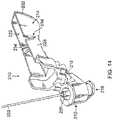
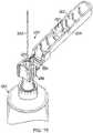
- FIG. 15is a perspective view of yet another exemplary hinged cap device 254 provided in accordance with aspects of the present invention, attached to a syringe 255.
- the hinged cap device 254incorporates a cap 256 connected to a needle hub 258 by a living hinge 259.
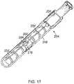
- the hinged cap device 254is moveable between a semi-locked or start position ( FIG. 16 ), in which the cap temporarily covers a needle 252, to an open position wherein the needle is exposed ( FIG. 15 ), from the open position to a capped position ( FIG. 17 ), and from the capped position to a locked position ( FIG. 18 ) in which the needle 252 is permanently trapped within the cap 256.
- the needle 252is attached directly to the coupling well 220 of the needle hub 258, although a needle attached to a separate needle hub is contemplated for use with a male luer connector to be located on the hinged cap device 254.
- the cap 256defines a generally U-shaped channel 262 adapted to house the needle 252.
- a catch mechanism 260is incorporated in the channel 262 defined by the cap 256.
- the catch mechanism 260is made from a metal material and is attached to the cap in a snap lock arrangement, such as detent, dove-tail, or tongue- and-groove lock arrangement.
- the catch mechanism 260may also be insert-molded into the cap.
- the cap 256is shown in an exposed position, which in one embodiment is about 120 degrees measured from the axis of the needle shaft and an axis defined by the lengthwise direction of the cap.
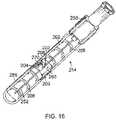
- FIG. 16is a perspective view of the hinged cap device 254 of FIG. 15 in the semi-locked or start position, that is also a packaged or shipped position.
- the lock mechanism 260comprises an anchor plate 200, that is similar to a tongue for engaging a groove located on the cap.
- a cantilevered member 202extends from the anchor plate 200, or to another section that extends from the anchor plate, and comprises an arcuate joint 203 and a hook arm 270, (more clearly shown on FIG. 19 ) that comprises an inactive surface 204 and an active surface 206, located on the hook arm facing in the opposite direction from the inactive surface 204.
- a plurality of ribs 208are optionally incorporated in the cap for enhancing the structural rigidity of the cap.
- the needle 252is positioned in a temporary locked position against the catch mechanism 260, in which the needle is held temporarily against the arcuate joint 203.
- the cap 256is pivoted radially outwardly to expose the needle, which deflects the needle 252 and/or the catch mechanism 260 to free the needle from the catch mechanism.
- the cap 256is pivoted until it is in the open position shown in FIG. 15 .
- the needleis now ready for use.
- FIG. 17is a perspective view of the hinged cap device 254 with the needle 252 pushed against the inactive surface 204 of the hook arm 270.
- the cap 214may be pivoted back in alignment over the needle 252 by pushing the cap, using either a finger to push the cap or pushing the cap against a surface. Care should be taken at this time not to fully lock the needle before administering the injection.
- the useragain pivots the cap 256 away from the needle ( FIG. 15 ) to the open position, administers the injection, and recaps the needle to the position shown in FIG. 17 .
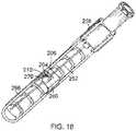
- FIG. 18is a perspective view of the needle 252 moved to a secured position.
- the needle 252is moved to the active surface 206 of the hook arm 270.
- thisis accomplished by pushing the cap 256 further upright so that the needle 252 is moved further into the channel 262 defined by the cap.
- This further movement on the capcauses the needle 252 to deflect, the hook arm 270 to deflect, or both.
- the hook arm 270is angled so that the plane defined by the inactive surface 204 ( FIG. 17 ) is angled or sloped relative to the plane defined by the motion of the cap. This orientation allows the needle, the hook arm, or both to deflect when the cap is pivoted.
- the capis pivoted until the needle 252 is moved past the end or ledge 264 of the hook arm 270, at which time the needle recoils or recovers and moves under the hook arm against the active surface 206.
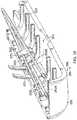
- FIG. 19is a partial perspective view of the hinged cap device 254 of FIG. 15 with the needle 252 shown in three different positions: (1) a start position, (2) a capped but not secured position, and (3) a secured position.
- the needle 252is positioned in a temporary locked position, indicated at 252A, against the arcuate joint 203 of the cantilevered member 202.
- the cap 256is pivoted outwardly in the direction of the open arrow 266, which deflects the needle free from the catch mechanism.
- the cap 256is pivoted in the direction of the closed arrow 268 until the needle 252 contacts the hook arm 270 of the catch mechanism, indicated at 252B.
- the hinged cap device 272may include any of the latching mechanisms described above, among others, and is shown with the cap pivoted away from a needle 252 , in an exposed or open position.
- the hub 274incorporates a flange 276 , including a lock lever 278 for locking a needle hub 280 having the needle 252 attached thereto and a socket 282 for receiving a boss 284 on the cap 286 .
- the cap 286further includes a gripping lever 288 for pushing or pulling on the cap to engage the boss 284 to the socket 282.
- the hinged cap deviceincludes two sockets 282, two bosses 284, and two gripping levers 288 located on opposite sides of the needle hub 274 and the cap 286.
- the cap 286may be rotated from the open position to a semi-locked position in which the cap 286 is aligned over the needle and the boss 284 is engaged in a first groove of the socket 282.
- the capIn the semi-locked position, the cap can be pivoted away from the needle to an open position or the gripping lever 288 may be pulled or pushed to move the boss to the second groove of the socket 282 to a locking position.
- the hinge 290is an articulating hinge, capable of both pivoting and translating to move the boss to a fully locked position.
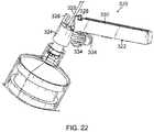
- the hinged cap device 320incorporates a cap 322 and a hub 324 for capturing and shielding a needle to prevent inadvertent needle stick.
- the hub 324incorporates a post 326 and a pair of catch arms 328 for grabbing or engaging the post 326.
- the catch arms 328extend from the two side walls 330 of the cap.
- a pair of lever arms 334also extend from the two side walls 330, but in a direction opposite from the two catch arms 328.
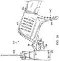
- FIGs. 23-27Yet another example of a hinged cap device 310 of the present disclosure is shown in FIGs. 23-27 .
- the hinged cap devicecomprises a base 312 connected to a cap 314 by a living hinge 18, the living hinge being biased toward an initial packaged or ready position.
- the capcan be rotated from the ready position to an open position ( FIG. 24 ), in which a needle 316 is exposed and from the open position to a secured position in which the needle 316 is secured within the cap by the first latching mechanism 24.
- a push tab 346is provided to aid in rotation of the cap 314 between various positions, the push tab including a gripping surface 347, for example, a plurality of raised protrusions or bumps, to provide a user with a more secure hold on the cap.
- the push tab 346may also be contoured to generally conform to a user's finger, thereby providing a comfortable feel for the user.
- the base 312includes a base engagement prong 348 having a detent or hook 350 at an end adapted to engage a detent or hook 354 on a cap engagement prong 352 to temporarily lock the cap 314 in the open position, as described in more detail below.
- the cap 314includes two side walls 311a, 311b, defining an open channel 313 therebetween.
- the cap 314further includes a second latching mechanism 340, including two latch walls 342, each latch wall extending orthogonally from one side wall 311a, 311b and including an undercut or notch 343 adapted to receive a respective tab 336 on the base 312, similarly to the examples described with respect to FIGs. 8 -iob .
- the notches 343form an acute angle with the latch wall 342 to provide additional security against rotation for the base 312 when the tabs 336 are engaged with the notches.
- a latch support wall 344extends perpendicularly from each latch wall 342 and having tapered or angled edges below generally constant upper edges for structurally supporting the latch wall 342.
- the upper generally constant edges 344a, 344bare configured to abut the base to delimit axial movement of the base relative to the cap, as further discussed below.
- the tabs 336 extending from the base 312have angled leading and trailing edges 337a, 337b that generally form an obtuse angle with a surface of the base that they contact and allow for easier disengagement from and engagement to the cap during rotation. Additionally, upper and lower surfaces 315a, 315b of the tabs 336 are generally sloped upward toward a reinforcement member 317 of the base 312 to substantially match an angle of the notch 343 such that the tabs generally form a V-shape with the base in cross-section.
- the sloped lower surface 315b on the two tabs 336provide less resistance between the latch walls 342 and the tabs 336 when the cap is rotated from the open position to the secured position, allowing easier rotation of the cap into the secured position.
- tabs and corresponding notchesof varying shapes, sizes, and configurations may be used without departing from the scope of the dislcosure.
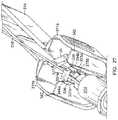
- the hinged cap device 310is shown in the open position wherein the cap 314 has been rotated such that the hook 354 on the cap engagement prong 352 is engaged with the hook 350 on the base engagement prong 348.
- a contact surface 355 of the cap engagement prongcontacts a contact surface 351 of the base engagement prong 348 and, if enough force is applied on the cap 314 toward the base 312, the engagement prongs 348, 352 deflect and snap into the temporary locked arrangement as shown.
- the componentsmay produce a sound or a vibration to indicate their engagement to a user.
- the contact surfaces 351, 355are arcuate to require less resistance to snap the engagement prongs 348, 352 together.
- a radial forcemay be applied to the cap 314 sufficient to deflect the engagement prongs and to allow the hooks 350, 354 to separate.
- the length of the hooks 350, 354 and the widths of the engagement prongs 348, 352may be varied based on the amount of force desired to disengage the engagement prongs.
- the usermay grasp the cap 314 at a contoured gripping surface 341 location of the side walls 311a, 311b, thereby slightly compressing and deforming the cap and causing the latch walls 342 to exert a radial pressure on the tabs 336.
- a usercan restrict relative axial movement between the base 312 and the cap 314 when the hinged cap device 310 is mounted onto a syringe.
- a hinged cap device having a rigid capcould still be suitable and mountable onto a syringe.
- to move the cap 314 from the ready positionFIG.
- the capis moved axially toward the base 312 to disengage the tabs 336 from the second latching mechanism 340.
- the relative axial movement between the base 312 and the cap 314is limited by the stopping edge 356 abutting the latch support walls 344, and more particularly the upper generally constant edges 344a, 344b. Either the base is held stationary and the cap is axially moved or vice versa or both.
- the cap 314may be rotated radially outwardly away from the needle 316 to expose the needle.
- the cap 314may be rotated radially inwardly toward the needle 316 where the first latching mechanism 24 will engage the needle and secure it under the acute angle side, as described above.
- the living hingeis configured with a self bias by sizing the tabs on either side of the living hinge with sufficient material and resiliency so that it tends to push the base and the cap axially away from one another toward the ready position to uncoil to its more relaxed position. As such, when the cap is moved to a locked position, the tabs 336 will reengage the notches 343 of the latch walls 342 by the bias action of the living hinge. However, as noted above, such reengagement is not necessary to secure the needle 316 within the cap 314. Additionally, one of ordinary skill in the art will appreciate that the living hinge does not need to be biased into the ready position.
- hinged cap embodiments or examples and their componentshave been specifically described and illustrated, many modifications, combinations, and variations of the embodiments or examples will be apparent to those skilled in the art.
- the length, size, colors, and other appearances of the hubmay be modified, and the needle may be attached directly to the hub on the hinged cap or as a separate hub attached via a luer fitting.
- features specifically discussed for one hinged cap embodiment or examplemay be adopted for inclusion with another hinged cap embodiment or example provided the functions are compatible.
- the hinged cap devices and their components constructed according to principles of this inventionmay be embodied other than as specifically described herein.
- the present disclosurefurther relates to the following aspects.
Landscapes
- Health & Medical Sciences (AREA)
- Engineering & Computer Science (AREA)
- Heart & Thoracic Surgery (AREA)
- Vascular Medicine (AREA)
- Anesthesiology (AREA)
- Biomedical Technology (AREA)
- Environmental & Geological Engineering (AREA)
- Hematology (AREA)
- Life Sciences & Earth Sciences (AREA)
- Animal Behavior & Ethology (AREA)
- General Health & Medical Sciences (AREA)
- Public Health (AREA)
- Veterinary Medicine (AREA)
- Infusion, Injection, And Reservoir Apparatuses (AREA)
Description
- The present invention relates generally to caps for a needle device, and more particularly, to hinged cap devices for use with hypodermic needles as defined in
claim 1. - Recapping is a common procedure for periods between drawing up fluids into a syringe and administering injections through a needle. The recapping procedure can occasionally cause needle sticks since users sometime misalign the needles with the openings on the caps, producing minimal pain but causing a great deal of inconvenience because all such needle stick incidences must be reported. Also, since needles related to the needle stick incidences must be discarded, medications contained within the syringes are unnecessarily wasted. Furthermore, fluids linked to these "clean" type of needle sticks can cause injuries and adverse reactions.
- Hinged cap devices of this kind are known in the state of the art.
US 5,490,841 discloses a needle protection device having an elongate housing with a longitudinal needle entrance portion defined between two housing side walls. At least one hinged door member is provided extending across the entrance portion to enclose the needle within the housing.US 4,976,699 discloses a protective cover for a syringe needle which maintains the sterility of the needle prior to use, is easily displaced with one hand in order to employ the syringe in the application of fluid transfer via its needle portion with the same hand, is readily repositioned back over the needle with the same hand, prevents reuse, indicates prior use, prevents accidental needle sticks, and is able to be manufactured cost-effectively. - In an effort to reduce or eliminate the source of "clean" needle stick injuries during recapping between drawing up fluids and administering an injection, it was necessary to improve the state of the art. The improvements will also minimize or eliminate the more dangerous types of needle stick injuries that occur after the needles have been contaminated with a patient's bodily fluids. In exemplary embodiments discussed below, hinged cap devices are packaged ready for use without additional removable caps. However, in some cases, a removable cap may still be used as necessary or desired.
- As further discussed below, using a hinged safety cap device having multiple positions will allow a user to safely cover a sharp needle tip during the periods between drawing up fluids and administering an injection to a patient. The needle can be covered without locking the device to allow the needle to be exposed when necessary. Before the user discards the device, such as after use, he or she can manipulate the hinged cap into a locked position so it can no longer be re-used or be exposed to cause needle stick injuries. In some exemplary embodiments, an audible, visual and/or tactile signal(s) is provided to the user as an indication that the cap is securely locked over the needle.
- A hinged cap device for use with a syringe includes a base defining an interior cavity for mounting onto a tip and a cap connected to the base by a living hinge. The cap is moveable from a ready position to an open position to expose a needle, and from the open position to a secured position to prevent relative rotation between the cap and the base. A first latching mechanism is on the cap for engaging the needle, the first latching mechanism locatable on a first side of the needle in the ready position and locatable on a second side of the needle in the secured position. The needle is disengageable from the first latching mechanism in the ready position, and the needle is not disengageable from the first latching mechanism in the secured position.
- In certain aspects of the present disclosure, the hinged cap assembly may optionally include a first latching mechanism having a projection attached to the cap and extending into the open channel and a catch lever straddling the projection to form an obtuse angle side and an acute angle side.
- The hinged cap device may also include a second latching mechanism on the cap for engaging at least one tab on the cap, the second latching mechanism dis-engageable from the at least one tab by axially moving the cap along a lengthwise axis of the needle relative to the hub. In certain aspects of the present disclosure, the second latching mechanism may optionally include a pair of latch walls, one latch wall extending from the first side wall and the second side wall, wherein each latch wall comprises a notch adapted to engage a respective base tab on the base.
- In another example of the present disclosure, the second latching mechanism may include a pair of tabs, one lab extending from both the first side wall and the second side wall, wherein each tab is adapted to abut a respective base tab on the base.
- In certain aspects of the present disclosure, the hinged cap assembly may further optionally include a base having a wedge and a cap having a pair of gripping plates, the wedge adapted to engage the gripping plates to temporarily maintain the cap in the open position. The hinged cap device may be a single integral device and the device may be injection molded. The hinged cap assembly may also optionally include a first side wall
having a notch having two end wall edges defining an angle therebetween. Additionally, a living hinge may be located on the cap spaced from the living hinge located between the cap and the base. - Also provided is a method for operating a hinged cap device including moving a cap axially along a lengthwise direction of a needle to distort the living hinge to disengage the second latching mechanism from the base and rotating the cap radially outwardly relative to the needle from the ready position to the open position to expose the needle, and engaging the cap to the base in the cap open position. The method may also include rotating the cap radially inwardly relative to the needle to shield the needle from the open position to the secured position, thereby engaging the needle latching mechanism with the needle.
FIG. 1 is a perspective view of a hinged cap device provided in accordance with aspects of the present disclosure;FIG. 2 is a perspective view of the hinged cap device ofFIG. 1 showing the cap in a packaged or pre-operative configuration;FIG. 3 is a partial perspective view of the hinged cap device ofFIG. 2 showing the engagement between the second latching mechanism and the base separated from one another;FIG. 4 is a side view of the hinged cap device ofFIG. 3 showing a living hinge partially distorted for uncapping the needle;FIG. 5 is a side view of the hinged cap device ofFIG. 1 showing the cap rotated away from the needle to expose the needle;FIG. 6 is a perspective end view of the hinged cap device ofFIG. 1 showing the cap rotated away from the needle to expose the needle;FIG. 7 is a perspective view of the hinged cap device ofFIG. 1 in a secured configuration;FIG. 8 is a cross-sectional detail view of a proximal end of a cap of another example of the hinged cap device in accordance with aspects of the present disclosure showing a second latch mechanism;FIG. 9a is a top view of the hinged cap device ofFIG. 8 in a ready position, looking at the channel of the cap;FIG 9b is a cross-sectional view of the hinged cap device ofFIG. 9a along the line B-B;FIG. 9c is a side detail view of the hinged cap device ofFIG. 8 with the base disengaged from the second latching mechanism;FIG. 10a is a side view of the hinged cap device ofFIG. 8 in a secured position, looking at the channel of the cap;FIG 10b is a cross-sectional view of the hinged cap device ofFIG. 9a along the line C-C;FIGs. 11, 12 and 13 are a side view, a bottom view, and a top view, respectively, of yet another exemplary hinged cap needle device provided in accordance with aspects of the present disclosure;FIG. 14 is a perspective view of the hinged cap device ofFIG. 11 shown with a needle attached to the base;FIG. 15 is a perspective view of an exemplary hinged cap device provided in accordance with aspects of the present invention, shown mounted on an end of a barrel;FIG. 16 is a perspective view of the hinged cap device ofFIG. 15 in the packaged position for a different viewing angle, shown with the needle rested against an inactive side of the catch mechanism;FIG. 17 is a perspective view of the hinged cap device ofFIG. 16 shown with the needle pushed against the catch mechanism, immediately prior to latching or locking;FIG. 18 is a perspective view of the hinged cap device ofFIG. 17 shown with the needle in a locked position;FIG. 19 is a schematic view of the hinged cap device ofFIG. 15 showing the three needle positions depicted inFIGs. 16-18 ;FIG. 20 is a side view of yet another exemplary embodiment of a hinged cap device provided in accordance with aspects of the present disclosure;FIG. 21 is a side view of the hinged cap device ofFIG. 20 in a semi-locked position;FIG. 22 is a perspective view of still another example of a hinged cap device provided in accordance with aspects of the present disclosure;FIG. 23 is a perspective view of yet another example of a hinged cap device provided in accordance with aspects of the present disclosure;FIG. 24 is a detail view of a base and a second latching mechanism of the hinged cap device ofFIG. 23 ;FIG. 25 is a partial perspective view of the hinged cap device ofFIG. 23 showing the engagement between the second latching mechanism and the base;FIG. 26 is a perspective end view of the hinged cap device ofFIG. 23 showing the cap rotated away from the needle to expose the needle and the cap temporarily locked to the base; andFIG. 27 is a perspective view of the hinged cap device ofFIG. 23 between an open position and a secured position.- The detailed description set forth below in connection with the appended drawings is intended as a description of exemplary embodiments or examples of a hinged cap assembly for use with needles having sharp needle tips provided in accordance with aspects of the present invention and is not intended to represent the only forms in which the present invention may be constructed or used. The description sets forth the features and the steps for constructing and using the hinged cap assembly of the present invention in connection with the illustrated embodiments. It is to be understood that the same or equivalent functions and structures may be accomplished by different embodiments and are also intended to be encompassed within
the scope of the present invention, especially those incorporating a combination of features shown in the different embodiments included herein. As denoted elsewhere herein, like element numbers are intended to indicate like or similar elements or features. - Referring now to
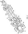
FIG. 1 , a perspective view of an exemplary hinged cap assembly of the present disclosure is shown, which is generally designated as10. Broadly speaking, the hingedcap assembly 10 comprises a base orhub 12 for mounting onto a syringe tip (not shown), the base defining an interior cavity therein, and acap 14 for shielding theneedle 16 preceding or following an injection. The hingedcap assembly 10 may be made by injection molding and, in one exemplary embodiment, is an integrally formed single unit in which thebase 12 is connected to thecap 14 by a livinghinge 18. As will be described in more detail below, thecap 14 is rotatable with respect to the base12 from a packaged or ready position (FIG. 2 ) to an open position (FIG. 1 ) and from the open position to a secured position (FIG. 7 ). - With reference now to
FIGs. 1 and2 , in one example of the present disclosure, thebase 12 includes twointegral cylinders second cylinder 12b having a smaller diameter than the first cylinder. Thefirst cylinder 12a is dimensioned to receive a syringe tip (not shown) of a syringe. The syringe tip and the hub may engage one another using Luer tapers with theflange 13 located at a proximal end of thefirst cylinder 12a optionally engaging a threaded collar on the syringe to form a Luer lock, as is well known in the art. An integral coaxialcylindrical needle holder 17 extends distally from thebase 12 for securing aneedle 16 to the base. Theneedle holder 17 is dimensioned with a smaller diameter than the base and is adapted to be received by ahub alignment mechanism 36 when the hingedcap device 10 is in the ready position and in the secured position, as described in more detail below. A stoppingedge 19 is formed by a distal surface of the second cylinder19b to limit axial movement of the base12 with respect to thecap 14, as described in more detail below. In an alternative example, the base may incorporate a male projection for engaging a separate combination needle hub and needle. The alternative male projection (not shown) may be a male Luer taper having an optional Luer lock, which may be a collar having internal threads, as is well known in the art. Optionally, a ridge orrib 15 in incorporated on thesecond cylinder 12b and theneedle holder 17 for reinforcement. In the example shown, two spaced apart ribs are incorporated, with only one shown. - The
cap 14 generally is configured to shield and contain theneedle 16 in the ready and secured positions to be easily manipulated between the ready and open positions; and to be easily manipulated between the open and secured positions. Thecap 14 comprises abase wall 28 and twoside walls open channel 22 therebetween. As seen more clearly inFIG. 5 , a profile of thecap 14 includes amiddle section 14b that extends deeper than adistal section 14a and aproximal section 14c. Thebase wall 28 substantially follows the contour of the profile and serves to support various components of the cap, as described in more detail below. Theside walls base wall 28 and are generally parallel to each other in theproximal section 14c of thecap 14. In the middle anddistal sections side walls end wall 21 extends between the twoside walls cap 14. In alternative examples of the present disclosure, theside walls - As shown in the figures, such as
FIGs. 1 and4 , a portion of theside wall 20a is cut away, for discussion purposes, to expose afirst latching mechanism 24 provided in accordance with aspects of the present disclosure. Thefirst latching mechanism 24 comprises acantilever projection 30 extending generally orthogonally of the base wall and asloped catch lever 32 integral with a top surface of the projection. In one example, theprojection 30 is attached to a circumferential surface of anopening 23 in thebase wall 28 located in themiddle portion 14b of thecap 14 and extends into thechannel 22. Since only a lower portion of theprojection 30 is attached to the opening, the projection has lateral flexibility with respect to a longitudinal axis of theneedle 16. Thesloped catch lever 32 straddles theprojection 30, forming an obtuse angle with one side of the projection and an acute angle on the other side of the projection. The obtuse angle side of thesloped catch lever 32 has a configuration such that when a bottom surface60 (FIG. 1 ) of the sloped catch
lever encounters theneedle 16 when the cap moves from a ready position to an open position, thefirst latch mechanism 24 is displaced and the catch lever can pass around the needle. Alternatively or in addition thereto, theneedle 16 may deflect or bend slightly to pass around the obtuse angle side. The acute angle side of thesloped catch lever 32 has a configuration such that when atop surface 58 of the catch lever encounters theneedle 16 when the cap moves from an open position to the secured position, thefirst latch mechanism 24 is displaced and/or the needle is deflected and the needle can then pass around the catch lever. However, if a user attempts to reposition thecap 14 into the open position from the secured position, and thereby pushes thebottom surface 60 of the acute angle side of thecatch lever 32 against the needle, the needle cannot laterally displace thefirst latch mechanism 24 nor can the needle pass around the sloped catch lever, thereby maintaining the hingedcap device 10 in the secured position. - With reference again to
FIG.2 , in one example of the present disclosure, thechannel 22 incorporates a firstneedle alignment mechanism 34 for aligning theneedle 16 to thecap 14, the first needle alignment mechanism being located within thedistal section 14a of the cap. The firstneedle alignment mechanism 34 comprises a pair of alignedvertical walls 34a, 34b, one wall extending perpendicularly from eachside wall needle 16 and align it with a longitudinal axis of thecap 14. Eachwall 34a, 34b of the firstneedle alignment mechanism 34 includes a sloped leadingedge 35 for directing theneedle 16 into the gap between the walls when the cap is rotated from an open position to a secured position. Similarly, thechannel 22 may incorporate a secondneedle alignment mechanism 50 having substantially the same structure as the first needle alignment mechanism in themiddle section 14b, for example, and located distally adjacent thefirst latching mechanism 24. - In another example of the present disclosure, a
hub alignment mechanism 36 may be incorporated into thecap 14 for aligning the base12 to the cap. Similarly to the first and secondneedle alignment mechanisms hub alignment mechanism 36 includes two spacedwalls side walls
between each wall having a sloped leadingedge 35. The gap between thewalls needle holder 17, and therefore is wider than the gap between walls of the first and secondneedle alignment mechanisms - Each
sidewall integral fin 39 extending proximally from about thehub alignment mechanism 36, the fins having a sloped top surface and a generally flat bottom surface. In one example of the present disclosure, thefins 39 includes an exterior indicia41 (FIG. 4 ), which may be, for example, a series of slightly raised protrusions, a roughened or corrugated surface, or a contoured surface. The exterior indicia41 adds to the aesthetic appeal of the cap. In other examples of the present disclosure, the cap may include lettering, symbols, or instructions. Alternatively or in addition,exterior indicia 41 indicates to a user where to hold thecap 14 and also to allow the user to attain a more secure grip of the cap when moving the cap between the various positions. An integral ear, lever, ortab 40 extends into thechannel 22, the tabs being generally located toward a lower, proximal portion of eachfin 39. Thetabs 40 are configured toabut corresponding tabs 38 extending from the base12 to prevent relative movement between thecap 14 and the base in the ready position. More specifically, thetabs 38 extend from thesecond cylinder 12b and have a flat bottom surface adapted to abut a flat top surface of thetabs 40. The two sets of tabs provide a temporary lock state and function as an added security feature when in the ready position. - The
base 12 is connected to thecap 14 by a livinghinge 18 located between abase segment 54 and acap segment 56. As showninFIGs. 1 and5 , thecap segment 56 extends proximally from a proximal end of thebase wall 28 and is generally parallel to a longitudinal axis of thecap 14. Thebase segment 54 extends at an angle from a wall surface of the base12 towards thecap segment 56 with the livinghinge 18 integrally joined therebetween such that the living hinge not only allows rotation of thecap 14 relative to thebase 12, but also allows for limited axial movement of the cap relative to the base to enable thetabs - With reference now also to
FIGS. 4 , thecap 14 comprises anintegral push lever 48 extending from thebase wall 28 away from thechannel 22. In one example of the present disclosure, a distally-facingsurface 49 of thepush lever 48 is generally arc-shaped and dimensioned to generally conform to the side of a user's finger. As such, the user can use thepush lever 48 to apply a compressive axial force toward a proximal end of the cap, and also apply a radial force to rotate thecap 14 with respect to thebase 12. One of ordinary skill in the art will appreciate that other configurations of a push lever, such as an orthogonal lever, may be used within the scope of aspects of the present disclosure. Additionally, a user may simply grab the twoside walls end wall 21 of the cap(FIG. 2 ) abuts the surface to create an axial force and a rotational force to open the cap. - With reference now to
FIGs. 4-6 , and initially toFIG. 6 , awedge 42 extends from a wall surface of thebase 12, the wedge having a slightly arcuate configuration. Thewedge 42 is dimensioned to fit between two spaced grippingplates 44 which extend from thebase wall 28 of the cap14 (FIG. 6 ). More specifically, thewedge 42 is located on the base12 such that when thecap 14 is rotated by a certain amount about the livinghinge 18 with respect to the base, the wedge engages thegripping plates 44 to temporarily retain the cap in the open position. In one example of the present disclosure, the engagement between thewedge 42 and thegripping plates 44 is a frictional engagement. However, one of ordinary skill in the art will appreciate that toothed surfaces or detents may be used without deviating from scope of the present disclosure. - The operation of the hinged cap assembly will now be described with reference to
FIGs. 2-7 . Initially, with reference toFIG. 2 , the hingedcap assembly 10 is shown in a packaged or ready position. As the name implies and although not shown, theassembly 10 may be packaged in the configuration shown inside a vacuum pack enclosure having a peelable cover configured for peeling to remove the assembly from the package. In this position, theneedle 16 is engaged on the obtuse angle side of thefirst latching mechanism 24
and extends through the first and secondneedle alignment members cap 14 is engaged to thebase 12 via abutting surfaces of thetabs needle holder 17 extends through thehub alignment mechanism 36. To rotate thecap 14 into the open position with respect to thebase 12 and expose theneedle 16, thetabs 40 on the cap are disengaged from thetabs 38 on the base. In one example of the present disclosure, thetabs cap 14 along a longitudinal axis of theneedle 16 towards the base such that the surfaces of thetabs FIG. 3 . The axial movement of thecap 14 with respect to the base12 causes the livinghinge 18 to curl or distort to accommodate for the axial movement of the cap, resulting in a portion of thecap segment 56 of the livinghinge 18 moving proximally of a portion of the base segment54 (FIG. 4 ). After a certain amount of axial movement, the stoppingedge 19 abuts thewalls cap 14. - As further shown in
FIG. 4 , the relative angle between thecap 14 and theneedle 16 indicates that the cap is rotating radially outwardly to free the needle from the obtuse side of thefirst latching mechanism 24. As noted above, when the bottom surface of thecatch lever 32 engages theneedle 16 during the cap rotation to expose the needle, the needle displaces thefirst latching mechanism 24 and/or the needle deflects to free the needle from the latching mechanism thus allowing the needle. With reference toFIG. 5 , thecap 14 has been disengaged from thefirst latching mechanism 24, and the cap is rotated radially outwardly relative to the needle axis to further expose theneedle 16. As shown inFIG. 6 , when thecap 14 is further rotated, thewedge 42 on the base engages thegripping plates 44 on the cap to temporarily retain the cap in the open position. In this position, an injection may be performed without thecap 14 interfering with theneedle 16. To place the hinged cap device in the secured position, as shown inFIG. 7 , the cap is rotated radially inwardly relative to the needle axis such that theneedle 16 encounters atop surface 58 of thecatch lever 32 and laterally displaces thefirst latching mechanism 24, or alternatively or in addition
thereto the needle deflects to allow the needle to pass around the first latching mechanism. Once theneedle 16 is located beneath the acute angle side of thecatch lever 32, the needle is secured beneath the catch lever and is prevented from laterally displacing thefirst latching mechanism 24 and/or from passing around the first latching mechanism regardless of whether thetabs 38/40 are engaged. Additionally, when the needle passes around the catch lever, an audible click and/or a slight vibration may be produced by the interaction of the components, informing a user that the needle has been secured. Although it is not necessary for maintaining the hingedcap device 10 in the secured position, thecap 14 may be moved distally along the needle longitudinal axis to uncurl the livinghinge 18 and reengage thetabs 38/40 to provide added security against unwanted rotation. - Another example of a hinged
cap device 110 of the present disclosure is provided with reference now toFIGs. 8 -iob. The hingedcap device 110 comprises abase 112 and a cap114 (FIG. 9a ) having a similar structure to those described above with respect to previous examples of the present disclosure. Thebase 112 is connected to thecap 114 by a living hinge. The base112 further comprises a temporary lock mechanism that, in the present example of the present disclosure, is in the form ofintegral tabs 128 extending from aneedle holder 117 adapted to engage asecond latching mechanism 126 on thecap 114. Thesecond latching mechanism 126 comprises a pair oflatch walls 122 extending perpendicularly fromside walls cap 114. Thelatch walls 122 have a slopedleading edge 135 for directing the temporary lock mechanism in between the gap located between the two walls when the cap is rotated from an open position to a secured position. Additionally, a channel-facingsurface 132 of thelatch walls 122 includes anotch 124, similar to a barb connector, adapted to engage thetabs 128 on thebase 112. A triangularlatch support wall 130 extends perpendicularly from the channel-facingsurface 132 of eachlatch wall 122 to delimit over-rotation of the cap when it engages the hub. - Similar to previously described examples of the present disclosure, the hinged
cap device 110 is transformable from a packaged or ready position to an open position and from an open position to a secured position. As shown inFIG. 9a and 9b , in the ready position, the needle
16 is located on the obtuse angle side of thefirst latching mechanism 24, and in contact with the projection on one side of its shaft surface, and a top surface of thetabs 128 on the hub or base abuts thenotch 124 on eachlatch wall 122 to prevent relative rotation between the base112 and thecap 114. To rotate thecap 114 into an open position, thetabs 128 may be disengaged from thenotches 124 by holding thehub 112 relatively fixed and moving thecap 114 along a longitudinal axis of theneedle 16 towards the base such that thetabs 128 are moved distally of the notches as shown inFIG. 9c to separate thetabs 128 from thenotches 124. The axial movement of thecap 114 with respect to the base112 causes the livinghinge 18 to curl or distort to accommodate for the axial movement of the cap. Accordingly, thecap 114 can now be rotated radially away from a longitudinal axis of theneedle 16 to expose the needle. In one example of the present disclosure, thecap 114 may be squeezed along the twoproximal end walls side walls cap device 110 in the secured position from the open position, thecap 114 is rotated radially back toward the needle axis such that the needles becomes trapped on the acute angle side of the first latch mechanism24 (FIGs. 10a and 10b ). As with previously described examples of the present disclosure, if desired, thecap 114 can be pulled distally to engage thenotches 124 with thetabs 128 for further security against relative rotations between the cap and the base118. - Referring to now
FIGs. 11-13 , a hingedcap device 210 provided in accordance with aspects of the present disclosure comprises ahub 212 and acap 214 connected to one another via ahinge 216. Thehub 212 has anopen end 218 for coupling to a syringe, aflange 219, and a coupling well220 for receiving a needle having a sharp needle tip (not shown). The coupling well220 is configured to grip and couple with the needle without a separate needle hub. - The
cap 214 comprises a generally U-shape channel comprising twoside walls 228, abase wall 230 and a curved orrounded end 232. A cut-out234 is incorporated on eachside wall 228 thus creating aliving hinge 236 at thebase wall 230 for pivoting thecurved end 232 of the housing over the needle to capture the needle, as further discussed below. In one
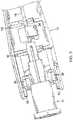
example of the present disclosure, the cut out has an angle of about 30 degrees, but one of ordinary skill in the art will appreciate that a cut out having an angle of between about 15 degrees to about 45 degrees or greater could also be used to pivot thecurved end 232 of the housing over the needle to capture the needle. An integrally formedlever 238 is incorporated for pulling or manipulating thecap 214 to shield the needle or to expose the needle from a semi-lock configuration. FIG. 12 is a top or plan view of the hingedcap assembly 210 ofFIG. 11 , looking down at thebase wall 230, the coupling well220, and achannel 222 defined by the twoside walls 228. Assuming that a needle is attached to the coupling well220, the hingedcap assembly 210 is shown in an open or exposed position with thecap 214 pivoted away from the needle to expose the needle tip.- A
round detent 240, which resembles a half-cylinder, is molded to one of theside walls 228. Asecond detent 242 is incorporated near the distal end of the cap, closer to therounded end 232 and on the other side of theliving hinge 236. Thesecond detent 242 resembles a downward leaf spring having one end integrally molded to thesame side wall 228 as the round detent and a free end pointed downward into thechannel 222. As further discussed below, theround detent 240 is configured to temporarily engage thecap 214 to the needle, such as during transport and prior to use. After use, thesecond detent 242 in combination with theliving hinge 236 is configured to more permanently secure the cap to the needle to prevent needle stick injuries. - Also shown is a
wide base section 244 of thecap 214, formed by providing an expandedshoulder 246. Thebase section 244 is configured to fit around or enwrap thehub 212 when the cap is in a closed or locked position. FIG. 13 is a bottom or reversed view ofFIG. 12 . Twoviewing windows base wall 230. The twoviewing windows semi-lock detent 240 and/or theleaf spring 242.- As briefly mentioned above, following an injection, the
cap 214 is configured to more permanently lock to the needle. Thesecond detent 242, in the form of a cantilevered ramp or leaf spring, supported at only one end so that the free end moves or deflects when pushed, is configured to more permanently lock the cap to the needle. Theleaf spring 242 has an upper surface or free side and a lower surface or lock side. In a semi-locked configuration, the needle is trapped below theround detent 240 and rests against the free side or upper surface of theleaf spring 242. In the semi-locked configuration, thecap 214 may be pivoted away from the needle by activating thelever 238, which deflects the needle away from theround detent 240. - To more permanently trap the needle within the
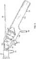
channel 222 of thecap 214, thecap 214 is first rotated upright over the needle until the needle engages theround detent 240. Thecurved end 232 of the cap is then pushed so that it pivots about the living hinge236 (FIG. 11 ). As thecurved end 232 pivots, thebase wall 230 and theleaf spring 242 moves in a corresponding radial direction. As theleaf spring 242 moves, the needle is forced under the free end of theleaf spring 242 and is trapped under the lower surface of the leaf spring. FIG. 14 is a semi-schematic perspective view of the hingedcap assembly 210 ofFIGs. 11-13 with thecap 214 in the open position. Aneedle 252 is shown attached to the coupling well220, without a separate needle hub.FIG. 15 is a perspective view of yet another exemplary hingedcap device 254 provided in accordance with aspects of the present invention, attached to asyringe 255. The hingedcap device 254 incorporates acap 256 connected to aneedle hub 258 by aliving hinge 259. The hingedcap device 254 is moveable between a semi-locked or start position (FIG. 16 ), in which the cap temporarily covers aneedle 252, to an open position wherein the needle is exposed (FIG. 15 ), from the open position to a capped position (FIG. 17 ), and from the capped position to a locked position (FIG. 18 ) in which theneedle 252 is permanently trapped within thecap 256. Theneedle 252 is attached directly to the coupling well220 of theneedle hub 258, although a needle attached to a separate needle hub is contemplated for use with a male luer connector to be located on the hingedcap device 254. In one exemplary
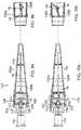
embodiment, thecap 256 defines a generallyU-shaped channel 262 adapted to house theneedle 252. Acatch mechanism 260 is incorporated in thechannel 262 defined by thecap 256. In one exemplary embodiment, thecatch mechanism 260 is made from a metal material and is attached to the cap in a snap lock arrangement, such as detent, dove-tail, or tongue- and-groove lock arrangement. Thecatch mechanism 260 may also be insert-molded into the cap. Thecap 256 is shown in an exposed position, which in one embodiment is about120 degrees measured from the axis of the needle shaft and an axis defined by the lengthwise direction of the cap.FIG. 16 is a perspective view of the hingedcap device 254 ofFIG. 15 in the semi-locked or start position, that is also a packaged or shipped position. As shown, thelock mechanism 260 comprises ananchor plate 200, that is similar to a tongue for engaging a groove located on the cap. A cantileveredmember 202 extends from theanchor plate 200, or to another section that extends from the anchor plate, and comprises an arcuate joint203 and ahook arm 270, (more clearly shown onFIG. 19 ) that comprises aninactive surface 204 and anactive surface 206, located on the hook arm facing in the opposite direction from theinactive surface 204. A plurality ofribs 208 are optionally incorporated in the cap for enhancing the structural rigidity of the cap.- In the start position shown in
FIG. 16 , theneedle 252 is positioned in a temporary locked position against thecatch mechanism 260, in which the needle is held temporarily against thearcuate joint 203. To use the needle, thecap 256 is pivoted radially outwardly to expose the needle, which deflects theneedle 252 and/or thecatch mechanism 260 to free the needle from the catch mechanism. Thecap 256 is pivoted until it is in the open position shown inFIG. 15 . The needle is now ready for use. FIG. 17 is a perspective view of the hingedcap device 254 with theneedle 252 pushed against theinactive surface 204 of thehook arm 270. Once fluids are drawn into the syringe255 (FIG. 15 ) for performing an injection, thecap 214 may be pivoted back in alignment over theneedle 252 by pushing the cap, using either a finger to push the cap or pushing the cap against a surface. Care should be taken at this time not to fully lock the
needle before administering the injection. To perform an injection, the user again pivots thecap 256 away from the needle (FIG. 15 ) to the open position, administers the injection, and recaps the needle to the position shown inFIG. 17 .FIG. 18 is a perspective view of theneedle 252 moved to a secured position. As shown, theneedle 252 is moved to theactive surface 206 of thehook arm 270. In one exemplary embodiment, this is accomplished by pushing thecap 256 further upright so that theneedle 252 is moved further into thechannel 262 defined by the cap. This further movement on the cap causes theneedle 252 to deflect, thehook arm 270 to deflect, or both. As is readily apparent to a person of ordinary skill in the art, thehook arm 270 is angled so that the plane defined by the inactive surface204 (FIG. 17 ) is angled or sloped relative to the plane defined by the motion of the cap. This orientation allows the needle, the hook arm, or both to deflect when the cap is pivoted. The cap is pivoted until theneedle 252 is moved past the end or ledge264 of thehook arm 270, at which time the needle recoils or recovers and moves under the hook arm against theactive surface 206.FIG. 19 is a partial perspective view of the hingedcap device 254 ofFIG. 15 with theneedle 252 shown in three different positions:(1) a start position, (2) a capped but not secured position, and (3) a secured position. In the start position, theneedle 252 is positioned in a temporary locked position, indicated at252A, against thearcuate joint 203 of the cantileveredmember 202. To use the needle, thecap 256 is pivoted outwardly in the direction of theopen arrow 266, which deflects the needle free from the catch mechanism. After use, thecap 256 is pivoted in the direction of theclosed arrow 268 until theneedle 252 contacts thehook arm 270 of the catch mechanism, indicated at252B. Further advancing the cap in theclosed arrow 268 direction will cause the needle to deflect due to thehook arm 270, the hook arm to deflect due to the needle, or both. As the needle moves across the tip or end264 of thehook arm 270, the needle is trapped on theactive side 206 of the hook arm, indicated at252C.- With reference now to
FIG. 20 , another example of a hingedcap device 272 according to the present disclosure mountable on a syringe is shown. The hingedcap device 272 may include any of
the latching mechanisms described above, among others, and is shown with the cap pivoted away from aneedle 252, in an exposed or open position. Thehub 274 incorporates aflange 276, including alock lever 278 for locking aneedle hub 280 having theneedle 252 attached thereto and asocket 282 for receiving aboss 284 on thecap 286. Thecap 286 further includes agripping lever 288 for pushing or pulling on the cap to engage theboss 284 to thesocket 282. In one example of the present disclosure, the hinged cap device includes twosockets 282, twobosses 284, and twogripping levers 288 located on opposite sides of theneedle hub 274 and thecap 286. - As shown in
FIG. 21 , thecap 286 may be rotated from the open position to a semi-locked position in which thecap 286 is aligned over the needle and theboss 284 is engaged in a first groove of thesocket 282. In the semi-locked position, the cap can be pivoted away from the needle to an open position or thegripping lever 288 may be pulled or pushed to move the boss to the second groove of thesocket 282 to a locking position. Thehinge 290 is an articulating hinge, capable of both pivoting and translating to move the boss to a fully locked position. - In another example of a hinged
needle device 320 as shown inFIG. 22 , provided in accordance with aspects of the present disclosure mountable on a syringe. Similar to other hinged cap device examples described herein, the hingedcap device 320 incorporates acap 322 and ahub 324 for capturing and shielding a needle to prevent inadvertent needle stick. Thehub 324 incorporates apost 326 and a pair ofcatch arms 328 for grabbing or engaging thepost 326. Thecatch arms 328 extend from the twoside walls 330 of the cap. A pair oflever arms 334 also extend from the twoside walls 330, but in a direction opposite from the twocatch arms 328. When the twocatch arms 328 are squeezed together, or towards one another, they deflect the two side walls, which then causes the two catch arms to move farther apart from one another. - Yet another example of a hinged
cap device 310 of the present disclosure is shown inFIGs. 23-27 . With reference now toFIG. 23 , the hinged cap device comprises a base312 connected to acap 314 by a livinghinge 18, the living hinge being biased toward an initial packaged or ready position. Similarly to previously described embodiments or examples, the cap can be rotated from the ready position to an open position (FIG. 24 ), in which aneedle 316 is exposed and from the open position to a secured position in which theneedle 316 is secured within the cap by thefirst latching mechanism 24. Apush tab 346 is provided to aid in rotation of thecap 314 between various positions, the push tab including agripping surface 347, for example, a plurality of raised protrusions or bumps, to provide a user with a more secure hold on the cap. Thepush tab 346 may also be contoured to generally conform to a user's finger, thereby providing a comfortable feel for the user. Additionally, thebase 312 includes abase engagement prong 348 having a detent or hook350 at an end adapted to engage a detent or hook354 on acap engagement prong 352 to temporarily lock thecap 314 in the open position, as described in more detail below. - With reference now to
FIGs. 24 and25 , thecap 314 includes twoside walls open channel 313 therebetween. Thecap 314 further includes asecond latching mechanism 340, including twolatch walls 342, each latch wall extending orthogonally from oneside wall respective tab 336 on thebase 312, similarly to the examples described with respect toFIGs. 8 -iob. In one example of the present disclosure, thenotches 343 form an acute angle with thelatch wall 342 to provide additional security against rotation for the base312 when thetabs 336 are engaged with the notches. Additionally, alatch support wall 344 extends perpendicularly from eachlatch wall 342 and having tapered or angled edges below generally constant upper edges for structurally supporting thelatch wall 342. The upper generallyconstant edges - With reference now also to
FIG. 27 , thetabs 336 extending from the base312 have angled leading and trailingedges lower surfaces tabs 336 are generally sloped upward toward areinforcement member 317 of thebase 312
to substantially match an angle of thenotch 343 such that the tabs generally form a V-shape with the base in cross-section. Additionally, the slopedlower surface 315b on the twotabs 336 provide less resistance between thelatch walls 342 and thetabs 336 when the cap is rotated from the open position to the secured position, allowing easier rotation of the cap into the secured position. As will be appreciated by one of ordinary skill in the art, tabs and corresponding notches of varying shapes, sizes, and configurations may be used without departing from the scope of the dislcosure. - With reference now to
FIG. 26 , the hingedcap device 310 is shown in the open position wherein thecap 314 has been rotated such that thehook 354 on thecap engagement prong 352 is engaged with thehook 350 on thebase engagement prong 348. As thecap 314 is rotated radially, acontact surface 355 of the cap engagement prong contacts acontact surface 351 of thebase engagement prong 348 and, if enough force is applied on thecap 314 toward thebase 312, the engagement prongs348, 352 deflect and snap into the temporary locked arrangement as shown. When the engagement prongs348, 352 are snapped together, the components may produce a sound or a vibration to indicate their engagement to a user. In one example of the present disclosure, the contact surfaces351, 355 are arcuate to require less resistance to snap the engagement prongs348, 352 together. To disengage the engagement prongs348, 352, a radial force may be applied to thecap 314 sufficient to deflect the engagement prongs and to allow thehooks hooks - To place the hinged
cap device 310 onto a syringe (not shown), the user may grasp thecap 314 at a contouredgripping surface 341 location of theside walls latch walls 342 to exert a radial pressure on thetabs 336. As such, a user can restrict relative axial movement between the base312 and thecap 314 when the hingedcap device 310 is mounted onto a syringe. However, one of ordinary skill in the art will appreciate that a hinged cap device having a
rigid cap could still be suitable and mountable onto a syringe. Similarly to previously described embodiments or examples, to move thecap 314 from the ready position (FIG. 25 ) to the open position (FIG. 26 ), the cap is moved axially toward the base312 to disengage thetabs 336 from thesecond latching mechanism 340. The relative axial movement between the base312 and thecap 314 is limited by the stoppingedge 356 abutting thelatch support walls 344, and more particularly the upper generallyconstant edges tabs 336 have been disengaged, thecap 314 may be rotated radially outwardly away from theneedle 316 to expose the needle. After use, thecap 314 may be rotated radially inwardly toward theneedle 316 where thefirst latching mechanism 24 will engage the needle and secure it under the acute angle side, as described above. In one example of the present disclosure, the living hinge is configured with a self bias by sizing the tabs on either side of the living hinge with sufficient material and resiliency so that it tends to push the base and the cap axially away from one another toward the ready position to uncoil to its more relaxed position. As such, when the cap is moved to a locked position, thetabs 336 will reengage thenotches 343 of thelatch walls 342 by the bias action of the living hinge. However, as noted above, such reengagement is not necessary to secure theneedle 316 within thecap 314. Additionally, one of ordinary skill in the art will appreciate that the living hinge does not need to be biased into the ready position. - Although limited hinged cap embodiments or examples and their components have been specifically described and illustrated, many modifications, combinations, and variations of the embodiments or examples will be apparent to those skilled in the art. For example, the length, size, colors, and other appearances of the hub may be modified, and the needle may be attached directly to the hub on the hinged cap or as a separate hub attached via a luer fitting. Furthermore, it is understood and contemplated that features specifically discussed for one hinged cap embodiment or example may be adopted for inclusion with another hinged cap embodiment or example provided the functions are compatible. Accordingly, it is to be understood that the hinged cap devices and their components constructed according to
principles of this invention may be embodied other than as specifically described herein. The present disclosure further relates to the following aspects. - Aspect 1: A hinged cap device for use with a syringe comprising: a base defining an interior cavity for mounting onto a tip; a cap comprising a base wall, a first side wall, and a second side wall defining an open channel, wherein the cap is connected to the base by a living hinge, and wherein the cap is moveable from a ready position to an open position to expose a needle, and from the open position to a secured position to prevent relative rotation between the cap and the base; a first latching mechanism on the cap for engaging the needle, the first latching mechanism locatable on a first side of the needle in the ready position and locatable on a second side of the needle in the secured position; wherein the needle is disengageable from the first latching mechanism in the ready position, and wherein the needle is not disengageable from the first latching mechanism in the secured position.
- Aspect 2: The hinged cap device of
aspect 1, wherein the first latching mechanism further comprises a projection attached to the cap and extending into the open channel; and a catch lever straddling the projection to form an obtuse angle side and an acute angle side. - Aspect 3: The hinged cap device of aspect 2, wherein the needle is on the obtuse angle side in the ready position and on the acute angle side in the secured position.
- Aspect 4: The hinged cap device of
aspect 1, wherein the first latching mechanism is laterally deflectable with respect to a longitudinal axis of the needle. - Aspect 5: The hinged cap device of
aspect 1, further comprising a second latching mechanism on the cap for engaging the base to prevent relative rotation between the cap and the base when the cap is in the ready position. - Aspect 6: The hinged cap device of aspect 5, wherein the base further comprises a pair of base tabs, and the second latching mechanism comprising a pair of latch walls, one latch wall extending from the first side wall and the second side wall, wherein each latch wall comprises a notch adapted to engage a respective base tab.
- Aspect 7: The hinged cap device of aspect 5, wherein the second latching mechanism comprises a pair of tabs, one tab extending from both the first side wall and the second side wall, wherein each tab is adapted to abut a respective base tab.
- Aspect 8: The hinged cap device of aspect 5, wherein the living hinge is distortable to allow the second latching mechanism to be disengaged from the base tabs.
- Aspect 9: The hinged cap device of
aspect 1, wherein the base further comprises a wedge and the cap further comprises a pair of gripping plates, the wedge adapted to engage the gripping plates to temporarily maintain the cap in the open position. - Aspect 10: The hinged cap device of
aspect 1 comprising a single integral device. - Aspect 11: The hinged cap device of
aspect 10, wherein the device is injection molded. - Aspect 12: A hinged cap device for use with a syringe comprising: a hub defining a cavity to receive a syringe for mounting onto a tip; a cap comprising a base wall, a first side wall, and a second side wall defining an open channel, the cap connected to the hub by a living hinge and rotatable between a ready position and a secured position; a first latching mechanism on the cap for engaging a needle to prevent relative rotation between the cap and the base when the cap is in the secured position; and a second latching mechanism on the hub for engaging at least one tab on the cap, said second latching mechanism dis-engageable from the at least one tab by axially moving the cap along a lengthwise axis of the needle relative to the hub.
- Aspect 13: The hinged cap device of
aspect 12, wherein the first latching mechanism further comprises a projection attached to the cap and extending into the open channel, and a catch lever straddling the projection to form an obtuse angle side and an acute angle side. - Aspect 14: The hinged cap device of
aspect 13, wherein the needle is on the obtuse angle side in the ready position, and wherein the needle is on the acute angle side in the secured position. - Aspect 15: The hinged cap device of
aspect 12, wherein the first latching mechanism is laterally deflectable with respect to a longitudinal axis of the needle. - Aspect 16: The hinged cap device of
aspect 12, wherein the second latching mechanism comprises at least one tab protruding from the hub for engaging at least one tab on the cap. - Aspect 17: The hinged cap device of
aspect 12, wherein the second latching mechanism comprises a pair of latch walls, one latch wall each extending from both the first side wall and the second side wall, and wherein each latch wall comprises a notch adapted to engage a respective tab on the hub. - Aspect 18: The hinged cap device of
aspect 12, wherein the second latching mechanism comprises a pair of cap tabs, one cap tab extending from both the first side wall and the second side wall, and wherein each cap tab is adapted to abut a respective tab on the hub. - Aspect 19: The hinged cap device of
aspect 12, wherein the living hinge is distortable to allow the second latching mechanism to be disengaged from the hub. - Aspect 20: The hinged cap device of
aspect 12, the hub further comprising a wedge and the cap further comprising a pair of gripping plates, the wedge adapted to engage the gripping plates to temporarily maintain the cap in an open position in which the needle is exposed. - Aspect 21: A method for operating a hinged cap device, the hinged cap device comprising a base for supporting a needle, a cap connected to the base by a living hinge, a needle latching mechanism on the cap for engaging the needle, the method comprising: moving a cap axially along a lengthwise direction of a needle to distort the living hinge to disengage the needle latching mechanism from the base; rotating the cap radially outwardly relative to the needle to expose the needle; and engaging the cap to the base in the cap open position.
- Aspect 22: The method of
aspect 21, the hinged cap device further comprising a base latching mechanism on the cap for engaging the base, the method further comprising rotating the cap radially inwardly relative to the needle to shield the needle and to engage the needle latching mechanism with the needle. - Aspect 23: The method of
aspect 22, the needle latching mechanism comprising an obtuse angle side and an acute angle side; wherein before rotating the cap radially outwardly, the needle is on the obtuse angle side; and wherein after rotating the cap radially inwardly, the needle is on the acute angle side. - Aspect 24: The hinged cap device of
aspect 1, wherein the first side wall comprises a notch having two end wall edges defining an angle therebetween. - Aspect 25: The hinged cap device of
aspect 24, further comprising a living hinge on the cap spaced from the living hinge located between the cap and the base. - The invention is defined in the following claims.
Claims (12)
- A hinged cap device (254) comprising:a needle hub (258) defining a cavity to receive a syringe for mounting onto a tip;the needle hub (258) comprising a needle (252) attached thereto;the needle (252) comprising a needle shaft and a needle tip;a cap (256) connected to the needle hub (258) by a hinge (259);said cap (256) comprising a base wall (230), a first side wall (228), and a second side wall (228) defining an open channel (262);wherein the cap (256) is moveable between a start position to an open position wherein the needle (252) is exposed, from the open position to a capped position, and from the capped position to a locked position in which the needle (252) is trapped within the cap (256);a catch mechanism (260) incorporated in the open channel (262) of the cap (256);the catch mechanism (260) further comprising a hook arm (270), the hook arm (270) comprising an end or a ledge (264), an inactive surface (204), and an active surface (206) located on the hook arm (270) facing in an opposite direction of the inactive surface (204);wherein in the capped position prior to locking, the needle (252) contacts the inactive surface (204) of the hook arm (270);wherein in the locked position, the needle (252) is trapped on the active surface (206) of the hook arm (206); andwherein the needle (252), the hook arm (270), or both the needle (252) and the hook arm (270) being deflectable such that the needle (252) is movable from the inactive surface (204) to the active surface (206) when the cap (256) is rotated radially inwardly relative to the needle (252) from the capped position to the locked positioncharacterized in thatthe catch mechanism (260) is made from a metal material and comprising an anchor plate (200) engaging the cap (256) in a snap lock arrangement, or by insert-molding.
- The hinged cap device (254) of claim 1, wherein the snap lock arrangement comprises a detent, dove-tail, or tongue-groove lock arrangement.
- The hinged cap device (254) of any of claim 1 or 2, wherein the catch mechanism (260) further comprises a cantilevered member (202) extending from the anchor plate (200).
- The hinged cap device (254) of any one of claims 1 to 3, wherein the anchor plate (200) is configured to engage a groove located on the cap (256).
- The hinged cap device (254) of any one of claims 1 to 4, wherein the cap (256) is movable from the capped position to the locked position when the cap (256) is pivoted until the needle (252) is moved past the end or the ledge (264) of the hook arm (270).
- The hinged cap device (254) of any one of claims 1 to 5, wherein the hook arm (270) is angled so that a plane defined by the inactive surface (204) is sloped relative to a plane defined by the motion of the cap (256) when the cap (256) is moved from the capped position to the locked position.
- The hinged cap device (254) of any one of claims 1 to 6 being a single integral device.
- The hinged cap device (254) of claim 7 being injection molded.
- The hinged cap device (254) of any one of claims 1 to 8, wherein the needle (252) is trapped on the active surface (206) of the hook arm (270) after the needle (252) moves across the end or the ledge (264) of the hook arm (270).
- The hinged cap device (254) of claim 3, wherein the cantilevered member (202) comprises an arcuate joint (203).
- The hinged cap device (254) of claim 10, wherein the arcuate joint (203) and the hook arm (270) are a part of the cantilevered member (202), which extends from the anchor plate (200).
- The hinged cap device (254) of any one of claims 1 to 11, wherein the hook arm (270) is deflectable such that the needle (252) is movable from the inactive surface (204) to the active surface (206) when the cap (256) is rotated radially inwardly relative to the needle (252) from the capped position to the locked position.
Applications Claiming Priority (4)
| Application Number | Priority Date | Filing Date | Title |
|---|---|---|---|
| US87624606P | 2006-12-21 | 2006-12-21 | |
| US11/962,078US8057431B2 (en) | 2006-12-21 | 2007-12-20 | Hinged cap for needle device |
| PCT/US2007/026234WO2008076459A1 (en) | 2006-12-21 | 2007-12-21 | Hinged cap for needle device |
| EP07853459.1AEP2094335B1 (en) | 2006-12-21 | 2007-12-21 | Hinged cap for needle device |
Related Parent Applications (2)
| Application Number | Title | Priority Date | Filing Date |
|---|---|---|---|
| EP07853459.1ADivisionEP2094335B1 (en) | 2006-12-21 | 2007-12-21 | Hinged cap for needle device |
| EP07853459.1ADivision-IntoEP2094335B1 (en) | 2006-12-21 | 2007-12-21 | Hinged cap for needle device |
Publications (2)
| Publication Number | Publication Date |
|---|---|
| EP2949355A1 EP2949355A1 (en) | 2015-12-02 |
| EP2949355B1true EP2949355B1 (en) | 2019-03-13 |
Family
ID=39536642
Family Applications (2)
| Application Number | Title | Priority Date | Filing Date |
|---|---|---|---|
| EP15170053.1AActiveEP2949355B1 (en) | 2006-12-21 | 2007-12-21 | Hinged cap for needle device |
| EP07853459.1AActiveEP2094335B1 (en) | 2006-12-21 | 2007-12-21 | Hinged cap for needle device |
Family Applications After (1)
| Application Number | Title | Priority Date | Filing Date |
|---|---|---|---|
| EP07853459.1AActiveEP2094335B1 (en) | 2006-12-21 | 2007-12-21 | Hinged cap for needle device |
Country Status (5)
| Country | Link |
|---|---|
| US (2) | US8057431B2 (en) |
| EP (2) | EP2949355B1 (en) |
| ES (2) | ES2564390T3 (en) |
| MY (2) | MY170947A (en) |
| WO (1) | WO2008076459A1 (en) |
Families Citing this family (107)
| Publication number | Priority date | Publication date | Assignee | Title |
|---|---|---|---|---|
| US7815663B2 (en) | 2006-01-27 | 2010-10-19 | Warsaw Orthopedic, Inc. | Vertebral rods and methods of use |
| US8038654B2 (en)* | 2007-02-26 | 2011-10-18 | Becton, Dickinson And Company | Syringe having a hinged needle shield |
| BRPI0817907B8 (en) | 2007-10-02 | 2021-06-22 | Lamodel Ltd | apparatus for administering a substance to an individual |
| US7967795B1 (en) | 2010-01-19 | 2011-06-28 | Lamodel Ltd. | Cartridge interface assembly with driving plunger |
| US9345836B2 (en) | 2007-10-02 | 2016-05-24 | Medimop Medical Projects Ltd. | Disengagement resistant telescoping assembly and unidirectional method of assembly for such |
| US10420880B2 (en) | 2007-10-02 | 2019-09-24 | West Pharma. Services IL, Ltd. | Key for securing components of a drug delivery system during assembly and/or transport and methods of using same |
| US9656019B2 (en) | 2007-10-02 | 2017-05-23 | Medimop Medical Projects Ltd. | Apparatuses for securing components of a drug delivery system during transport and methods of using same |
| EP2296735A4 (en)* | 2008-05-14 | 2013-05-29 | John Stephens | Needle protective device |
| US12097357B2 (en) | 2008-09-15 | 2024-09-24 | West Pharma. Services IL, Ltd. | Stabilized pen injector |
| US9393369B2 (en) | 2008-09-15 | 2016-07-19 | Medimop Medical Projects Ltd. | Stabilized pen injector |
| US20100256450A1 (en)* | 2008-10-24 | 2010-10-07 | Seung Wook Choi | Laparoscope and setting method thereof |
| EP2201971A1 (en)* | 2008-12-23 | 2010-06-30 | Sanofi-Aventis Deutschland GmbH | Drug delivery device |
| US8118840B2 (en) | 2009-02-27 | 2012-02-21 | Warsaw Orthopedic, Inc. | Vertebral rod and related method of manufacture |
| SE534021C2 (en) | 2009-08-13 | 2011-04-05 | Vigmed Ab | Protective device for a catheter needle tip |
| US10071196B2 (en) | 2012-05-15 | 2018-09-11 | West Pharma. Services IL, Ltd. | Method for selectively powering a battery-operated drug-delivery device and device therefor |
| US10071198B2 (en) | 2012-11-02 | 2018-09-11 | West Pharma. Servicees IL, Ltd. | Adhesive structure for medical device |
| USD810279S1 (en) | 2009-09-15 | 2018-02-13 | Medimop Medical Projects Ltd. | Injector device |
| US8157769B2 (en) | 2009-09-15 | 2012-04-17 | Medimop Medical Projects Ltd. | Cartridge insertion assembly for drug delivery system |
| US9011494B2 (en) | 2009-09-24 | 2015-04-21 | Warsaw Orthopedic, Inc. | Composite vertebral rod system and methods of use |
| US8348898B2 (en) | 2010-01-19 | 2013-01-08 | Medimop Medical Projects Ltd. | Automatic needle for drug pump |
| EP2569031B1 (en) | 2010-05-10 | 2017-10-11 | Medimop Medical Projects Ltd. | Low volume accurate injector |
| RU2584388C2 (en)* | 2010-11-22 | 2016-05-20 | Б. Браун Мельзунген Аг | Hinged panel device and related methods |
| CA2827415C (en)* | 2011-02-14 | 2018-10-23 | Terumo Kabushiki Kaisha | Safety needle assembly |
| US8764711B2 (en) | 2011-02-28 | 2014-07-01 | Injectimed, Inc. | Needle guard |
| US9238104B2 (en) | 2011-02-28 | 2016-01-19 | Injectimed, Inc. | Needle guard |
| USD702834S1 (en) | 2011-03-22 | 2014-04-15 | Medimop Medical Projects Ltd. | Cartridge for use in injection device |
| CN202724375U (en)* | 2011-05-06 | 2013-02-13 | 上海萌黎国际贸易有限公司 | Safety needle assembly |
| ES3005911T3 (en)* | 2011-07-05 | 2025-03-17 | Greiner Bio One Gmbh | Needle guard with an active state and a passive state |
| CA2854003C (en) | 2011-11-07 | 2020-07-14 | Safety Syringes, Inc. | Contact trigger release needle guard |
| BR112014019775A8 (en)* | 2012-03-08 | 2021-05-18 | Becton Dickinson Co | |
| US9072827B2 (en) | 2012-03-26 | 2015-07-07 | Medimop Medical Projects Ltd. | Fail safe point protector for needle safety flap |
| CN103520807A (en)* | 2012-07-04 | 2014-01-22 | 无锡市宇寿医疗器械股份有限公司 | Device capable of restraining injection needle cross infection |
| IL221634A0 (en) | 2012-08-26 | 2012-12-31 | Medimop Medical Projects Ltd | Universal drug vial adapter |
| CN103405831B (en)* | 2012-10-30 | 2015-07-08 | 张林锋 | Safety syringe |
| US9421323B2 (en) | 2013-01-03 | 2016-08-23 | Medimop Medical Projects Ltd. | Door and doorstop for portable one use drug delivery apparatus |
| WO2014121119A1 (en) | 2013-02-01 | 2014-08-07 | Nxstage Medical, Inc. | Safe cannulation devices, methods, and systems |
| US8721619B1 (en) | 2013-03-06 | 2014-05-13 | Nellin Medical Devices, LLC | Safety device |
| US9011164B2 (en) | 2013-04-30 | 2015-04-21 | Medimop Medical Projects Ltd. | Clip contact for easy installation of printed circuit board PCB |
| DE212014000169U1 (en) | 2013-08-07 | 2016-03-14 | Medimop Medical Projects Ltd. | Fluid transfer devices for use with infusion fluid containers |
| CN105431183B (en)* | 2013-08-07 | 2019-07-30 | 百时美施贵宝公司 | Injection aid and application method for being used together with injection device |
| CN103751889A (en)* | 2014-01-21 | 2014-04-30 | 淮安市恒春医疗器材有限公司 | Safety self-destructive syringe |
| CN103908710A (en)* | 2014-03-26 | 2014-07-09 | 温州市贝普科技有限公司 | Safety syringe |
| JPWO2015151596A1 (en) | 2014-03-31 | 2017-04-13 | ニプロ株式会社 | Safety equipment for syringes and needles |
| US9867951B2 (en)* | 2014-04-08 | 2018-01-16 | B. Braun Melsungen Ag | Hinged cap needle assemblies and related methods |
| JPWO2016002389A1 (en)* | 2014-07-02 | 2017-04-27 | テルモ株式会社 | Safety needle assembly |
| GB2532979A (en)* | 2014-12-04 | 2016-06-08 | Owen Mumford Ltd | Needle assemblies |
| US20160158458A1 (en)* | 2014-12-07 | 2016-06-09 | Wuxi Yushou Medical Appliances Co., Ltd. | Safe Injection Device Capable of Locking Needle |
| JP6358724B2 (en) | 2015-01-05 | 2018-07-18 | ウエスト・ファーマ.サービシーズ・イスラエル,リミテッド | Dual vial adapter assembly with easy removable pill adapter to ensure accurate use |
| US10029049B2 (en) | 2015-03-19 | 2018-07-24 | B. Braun Melsungen Ag | Hinged shield assemblies and related methods |
| US10293120B2 (en) | 2015-04-10 | 2019-05-21 | West Pharma. Services IL, Ltd. | Redundant injection device status indication |
| US10149943B2 (en) | 2015-05-29 | 2018-12-11 | West Pharma. Services IL, Ltd. | Linear rotation stabilizer for a telescoping syringe stopper driverdriving assembly |
| CN113181477B (en) | 2015-06-04 | 2023-07-14 | 麦迪麦珀医疗工程有限公司 | Cartridge insertion for drug delivery device |
| KR101685689B1 (en)* | 2015-06-11 | 2016-12-13 | (주)가이버 | Safety cap for disposable syringe |
| WO2017009822A1 (en) | 2015-07-16 | 2017-01-19 | Medimop Medical Projects Ltd | Liquid drug transfer devices for secure telescopic snap fit on injection vials |
| US10576207B2 (en) | 2015-10-09 | 2020-03-03 | West Pharma. Services IL, Ltd. | Angled syringe patch injector |
| US9987432B2 (en) | 2015-09-22 | 2018-06-05 | West Pharma. Services IL, Ltd. | Rotation resistant friction adapter for plunger driver of drug delivery device |
| US11318254B2 (en) | 2015-10-09 | 2022-05-03 | West Pharma. Services IL, Ltd. | Injector needle cap remover |
| CN115721558A (en) | 2015-11-25 | 2023-03-03 | 西部制药服务以色列有限公司 | Dual vial adapter assembly comprising a drug vial adapter having a self-sealing inlet valve |
| JP6885960B2 (en) | 2016-01-21 | 2021-06-16 | ウェスト ファーマ サービシーズ イスラエル リミテッド | Drug delivery device with visual indicators |
| EP3711793B1 (en) | 2016-01-21 | 2021-12-01 | West Pharma Services IL, Ltd. | A method of connecting a cartridge to an automatic injector |
| US10646643B2 (en) | 2016-01-21 | 2020-05-12 | West Pharma. Services IL, Ltd. | Needle insertion and retraction mechanism |
| US11389597B2 (en) | 2016-03-16 | 2022-07-19 | West Pharma. Services IL, Ltd. | Staged telescopic screw assembly having different visual indicators |
| IL245800A0 (en) | 2016-05-24 | 2016-08-31 | West Pharma Services Il Ltd | Dual vial adapter assemblages including identical twin vial adapters |
| IL245803A0 (en) | 2016-05-24 | 2016-08-31 | West Pharma Services Il Ltd | Dual vial adapter assemblages including vented drug vial adapter and vented liquid vial adapter |
| CN109310831B (en) | 2016-06-02 | 2021-11-23 | 西医药服务以色列有限公司 | Three position needle retraction |
| IL246073A0 (en) | 2016-06-06 | 2016-08-31 | West Pharma Services Il Ltd | Fluid transfer devices for use with drug pump cartridge having slidable driving plunger |
| JP7059251B2 (en) | 2016-08-01 | 2022-04-25 | ウェスト ファーマ サービシーズ イスラエル リミテッド | A spring that prevents the door from closing halfway |
| US11338090B2 (en) | 2016-08-01 | 2022-05-24 | West Pharma. Services IL, Ltd. | Anti-rotation cartridge pin |
| IL247376A0 (en) | 2016-08-21 | 2016-12-29 | Medimop Medical Projects Ltd | Syringe assembly |
| CN106730172B (en)* | 2016-11-11 | 2023-05-23 | 贝普医疗科技股份有限公司 | Safety injection needle |
| JP7047271B2 (en)* | 2017-07-14 | 2022-04-05 | ニプロ株式会社 | Needle assembly and needle device equipped with it |
| US11185638B2 (en)* | 2016-12-02 | 2021-11-30 | Nipro Corporation | Needle assembly and needle device having same |
| IL249408A0 (en) | 2016-12-06 | 2017-03-30 | Medimop Medical Projects Ltd | Liquid transfer device for use with infusion liquid container and pincers-like hand tool for use therewith for releasing intact drug vial therefrom |
| US12064609B2 (en)* | 2016-12-14 | 2024-08-20 | Star Syringe Limited | Needlestick prevention device |
| KR102035551B1 (en)* | 2017-02-20 | 2019-10-23 | 박선명 | Safety filter syringe |
| KR101940275B1 (en)* | 2017-02-27 | 2019-01-18 | 주식회사 밴드골드 | Safety sylinge |
| IL251458A0 (en) | 2017-03-29 | 2017-06-29 | Medimop Medical Projects Ltd | User actuated liquid drug transfer devices for use in ready-to-use (rtu) liquid drug transfer assemblages |
| EP3630226A1 (en) | 2017-05-30 | 2020-04-08 | West Pharma. Services Il, Ltd. | Modular drive train for wearable injector |
| IL254802A0 (en) | 2017-09-29 | 2017-12-31 | Medimop Medical Projects Ltd | Dual vial adapter assemblages with twin vented female vial adapters |
| JP7402799B2 (en) | 2017-12-22 | 2023-12-21 | ウェスト ファーマ サービシーズ イスラエル リミテッド | Syringes available with different cartridge sizes |
| US11083847B2 (en) | 2018-01-26 | 2021-08-10 | Becton, Dickinson And Company | Flush syringe with flip cap |
| ES2938996T3 (en) | 2018-01-30 | 2023-04-18 | Becton Dickinson Co | Universal plug or connector for male and female threaded accessories |
| US11273298B2 (en) | 2018-04-10 | 2022-03-15 | Becton, Dickinson And Company | Universal single-use cap for male and female connectors |
| JP7089169B2 (en)* | 2018-05-14 | 2022-06-22 | 株式会社トップ | Needle protection |
| JP1630477S (en) | 2018-07-06 | 2019-05-07 | ||
| KR102557433B1 (en)* | 2018-11-27 | 2023-07-21 | 주식회사 대웅제약 | Safety cap for syringe and safety syringe including the same |
| USD923812S1 (en) | 2019-01-16 | 2021-06-29 | West Pharma. Services IL, Ltd. | Medication mixing apparatus |
| JP1648075S (en) | 2019-01-17 | 2019-12-16 | ||
| JP7209849B2 (en) | 2019-01-18 | 2023-01-20 | ウェスト・ファーマ・サービシーズ・アイエル・リミテッド | Liquid transfer device for use with IV bottles |
| US11511100B2 (en) | 2019-01-30 | 2022-11-29 | Becton, Dickinson And Company | Universal cap for male and female connectors |
| US11918542B2 (en) | 2019-01-31 | 2024-03-05 | West Pharma. Services IL, Ltd. | Liquid transfer device |
| JP7284289B2 (en) | 2019-04-09 | 2023-05-30 | ウェスト ファーマ サービシーズ イスラエル リミテッド | Infusion device with integrated syringe |
| KR20240122586A (en) | 2019-04-30 | 2024-08-12 | 웨스트 파마. 서비시즈 일, 리미티드 | Liquid transfer device with dual lumen iv spike |
| MX2021014537A (en)* | 2019-05-31 | 2022-02-11 | Metier Medical Ltd | Needle cover and safety needle assembly including same. |
| BR112022000161A2 (en)* | 2019-07-12 | 2022-02-22 | Becton Dickinson Co | Syringe tip cap |
| CA3145028A1 (en) | 2019-08-08 | 2021-02-11 | Chang JIANG | Universal cap with pressure seal |
| US11266792B2 (en)* | 2019-10-28 | 2022-03-08 | FGC Holdings Limited | Single use safety needle guard |
| US11975168B2 (en) | 2019-11-18 | 2024-05-07 | Becton, Dickinson And Company | Disinfectant cap |
| US12029828B2 (en) | 2020-03-05 | 2024-07-09 | Becton, Dickinson And Company | Disinfection cap |
| US12005244B2 (en) | 2020-03-27 | 2024-06-11 | Medivena Sp. Z O.O. | Needle-based device based on direct wing-based coupling of a needle shield to a barrel thereof and safety mechanism implemented therein |
| US11969572B2 (en) | 2020-04-17 | 2024-04-30 | Becton, Dickinson And Company | Disinfection cap |
| US12383719B2 (en) | 2020-04-17 | 2025-08-12 | Becton, Dickinson And Company | Disinfecting cap with re-use prevention |
| US12005223B2 (en) | 2020-04-17 | 2024-06-11 | Becton, Dickinson And Company | Disinfection cap |
| WO2021259953A1 (en)* | 2020-06-23 | 2021-12-30 | Becton Dickinson France | Safety device for a needle |
| USD956958S1 (en) | 2020-07-13 | 2022-07-05 | West Pharma. Services IL, Ltd. | Liquid transfer device |
| DE102022111083A1 (en) | 2022-05-05 | 2023-11-09 | Stephan Fischer | Protective device for a needle tube of a syringe |
| DE102023126547A1 (en)* | 2023-09-28 | 2025-04-03 | Dispomed GmbH & Co. KG | Angled cannula guard for one-handed operation and arrangement |
Citations (2)
| Publication number | Priority date | Publication date | Assignee | Title |
|---|---|---|---|---|
| US4976699A (en)* | 1989-05-24 | 1990-12-11 | Gold Steven K | Needle and safety cover assembly for syringes and the like |
| US20050075609A1 (en)* | 2003-10-01 | 2005-04-07 | Latona Patrick C. | Protective needle clips |
Family Cites Families (286)
| Publication number | Priority date | Publication date | Assignee | Title |
|---|---|---|---|---|
| US3658061A (en) | 1970-11-10 | 1972-04-25 | Baxter Laboratories Inc | Needle guard |
| US4664259A (en) | 1985-05-13 | 1987-05-12 | Robert Landis | Needle container and method for preventing accidental contact with a needle |
| US5549572A (en) | 1985-07-29 | 1996-08-27 | British Technology Group, Ltd. | Safety device for hypodermic needle or the like |
| US5536257A (en) | 1986-07-23 | 1996-07-16 | British Technology Group Ltd. | Safety device for hypodermic needle or the like |
| US4826490A (en) | 1985-07-29 | 1989-05-02 | National Research Development Corporation | Safety device for hypodermic needle or the like |
| GB8519049D0 (en) | 1985-07-29 | 1985-09-04 | Bryne P O | Safety device |
| USRE36447E (en) | 1985-07-29 | 1999-12-14 | Btg International Limited | Safety device for hypodermic needle or the like |
| EP0242373A1 (en) | 1985-10-11 | 1987-10-28 | Physionic Gesellschaft Für Medizin- Und Systemtechnik Gmbh | Injection syringe |
| US4631057A (en) | 1985-12-17 | 1986-12-23 | Dolores A. Smith | Shielded needle |
| US4639250A (en) | 1986-02-20 | 1987-01-27 | Becton, Dickinson And Company | Syringe barrel and hypodermic needle assembly |
| US4778453A (en) | 1986-04-07 | 1988-10-18 | Icu Medical, Inc. | Medical device |
| US4931048A (en) | 1986-04-07 | 1990-06-05 | Icu Medical, Inc. | Medical device |
| US4666435A (en) | 1986-05-22 | 1987-05-19 | Braginetz Paul A | Shielded medical syringe |
| US4775369A (en) | 1986-09-09 | 1988-10-04 | Boris Schwartz | Automatically actionable sharpened needle-tip protection |
| US4731059A (en) | 1986-10-14 | 1988-03-15 | Medical Safety Products, Inc. | Combination needle shield/needle guard device positively locked onto detachable needle assemblies for an evacuated blood collection system and a hypodermic syringe |
| ES2020280B3 (en) | 1986-11-19 | 1991-08-01 | Sterimatic Holdings Ltd | IMPROVEMENTS IN OR RELATED TO SYRINGES. |
| US4723943A (en) | 1986-12-31 | 1988-02-09 | Montana Deaconess Medical Center | Sheathed syringe |
| US4795432A (en) | 1987-02-19 | 1989-01-03 | Karczmer Claude M | Shield assembly for hypodermic injection devices |
| US4832696A (en) | 1987-03-05 | 1989-05-23 | Luther Medical Products, Inc. | Assembly of needle and protector |
| US4816024A (en) | 1987-04-13 | 1989-03-28 | Icu Medical, Inc. | Medical device |
| US4747837A (en) | 1987-05-01 | 1988-05-31 | Hauck Martin W | Syringe needle recapping protective device |
| US4804371A (en) | 1987-05-06 | 1989-02-14 | Vaillancourt Vincent L | Post-injection needle sheath |
| US4725267A (en) | 1987-05-06 | 1988-02-16 | Vaillancourt Vincent L | Post-injection needle sheath |
| US4850968A (en) | 1987-07-27 | 1989-07-25 | Ar.Ma.S.R.L. | Self-blocking hypodermic syringe for once-only use, comprising a needle protection cap |
| US4850961A (en) | 1987-07-30 | 1989-07-25 | Wanderer Alan A | Indwelling placement device with guard |
| US4804372A (en) | 1987-09-08 | 1989-02-14 | Laico Joseph P | Protective sheath for hypodermic needle |
| US4927416A (en) | 1987-12-02 | 1990-05-22 | National Medical Device Corporation | User-protective hypodermic syringe holder |
| US4887998A (en) | 1987-12-14 | 1989-12-19 | Martin Catherine L | Hypodermic needle guard |
| US4850977A (en) | 1988-01-29 | 1989-07-25 | Bayless William B | Button activated automatic needle sheath for disposable syringe |
| US4863434A (en) | 1988-01-29 | 1989-09-05 | Bayless William B | Automatic needle sheath for disposable syringe |
| US4820277A (en) | 1988-02-16 | 1989-04-11 | Norelli Robert A | Safety cover for syringe needles |
| US4850996A (en) | 1988-02-22 | 1989-07-25 | Cree Ian C | Safety needle |
| US4950250A (en) | 1988-02-23 | 1990-08-21 | Habley Medical Technology Corporation | Collapsible needle cover |
| US4935013A (en) | 1988-02-23 | 1990-06-19 | Habley Medical Technology Corporation | Collapsible needle cover |
| US4846809A (en) | 1988-02-29 | 1989-07-11 | Winifred Sims | Needle tip protective device |
| US4923446A (en) | 1988-04-14 | 1990-05-08 | Page Mary J | Shield for devices capable of penetrating skin |
| GB2217991A (en) | 1988-05-03 | 1989-11-08 | John Cole | Needle protection |
| JPH03504205A (en) | 1988-05-06 | 1991-09-19 | ディークス,デビッド,ジョン | Needle |
| US4867746A (en) | 1988-05-23 | 1989-09-19 | Becton, Dickinson And Company | Needle shield |
| US4932940A (en) | 1988-06-06 | 1990-06-12 | Walker Cedric F | Needle guard device |
| US5053018A (en) | 1988-06-28 | 1991-10-01 | Sherwood Medical Company | Combined syringe and needle shield and method of manufacture |
| US5156599A (en) | 1988-06-28 | 1992-10-20 | Sherwood Medical Company | Syringe and sliding locking needle shield |
| US5160326A (en) | 1988-06-28 | 1992-11-03 | Sherwood Medical Company | Combined syringe and needle shield |
| US5217437A (en) | 1988-06-28 | 1993-06-08 | Sherwood Medical Company | Needle protecting device |
| US5147326A (en) | 1988-06-28 | 1992-09-15 | Sherwood Medical Company | Combined syringe and needle shield and method of manufacture |
| US5169392A (en) | 1988-06-28 | 1992-12-08 | Sherwood Medical Company | Combined syringe and needle shield and method of manufacture |
| US4927417A (en) | 1988-07-07 | 1990-05-22 | Schneider Medical Technologies, Inc. | Safety sleeve adapter |
| US4952207A (en) | 1988-07-11 | 1990-08-28 | Critikon, Inc. | I.V. catheter with self-locating needle guard |
| US4892521A (en) | 1988-08-03 | 1990-01-09 | Lincoln Mills, Inc. | Protective cover for hypodermic needle |
| US4929241A (en) | 1988-08-05 | 1990-05-29 | Kulli John C | Medical needle puncture guard |
| US4978344A (en) | 1988-08-11 | 1990-12-18 | Dombrowski Mitchell P | Needle and catheter assembly |
| US4863435A (en) | 1988-08-24 | 1989-09-05 | Sturman Martin F | Safety hypodermic syringe |
| US4921490A (en) | 1988-08-24 | 1990-05-01 | Spier Martin I | Safety hypodermic needle syringe |
| US4888002A (en) | 1988-08-30 | 1989-12-19 | Braginetz Paul A | Disposable shield medical syringe |
| CA1315166C (en) | 1988-10-05 | 1993-03-30 | John S. Parry | Injection devices |
| US4911706A (en) | 1988-10-14 | 1990-03-27 | Regents Of The University Of Minnesota | Automatic needle cover |
| US4955866A (en) | 1988-10-19 | 1990-09-11 | University Of Florida | Hypodermic needle recapping device |
| US4917673A (en) | 1988-10-31 | 1990-04-17 | Coplin Allan J | Assembly for the protection against inadvertent puncture by medical needles |
| US4929237A (en) | 1988-11-07 | 1990-05-29 | David Medway | Hypodermic needle protection device |
| US4900311A (en) | 1988-12-06 | 1990-02-13 | Lawrence Stern | Hypodermic syringe |
| US4894055A (en) | 1988-12-28 | 1990-01-16 | Sudnak Paul J | Needle guard assembly for use with hypodermic syringes and the like |
| US4985021A (en) | 1989-01-31 | 1991-01-15 | Jeff Straw | Safety enclosure system for medical devices |
| US5662610A (en) | 1989-02-01 | 1997-09-02 | Sircom; Richard C. | Automatic needle guard tip protection |
| US6017329A (en) | 1989-03-02 | 2000-01-25 | Hake; Lawrence W. | Hypodermic needle guard and method to prevent needle stick injuries |
| US5843041A (en) | 1989-03-02 | 1998-12-01 | Hake; Lawrence W. | Hypodermic needle guard and method to prevent needle stick injuries |
| US5141500A (en) | 1989-03-02 | 1992-08-25 | Lawrence W. Hake | Hypodermic needle guard |
| US5314414A (en) | 1989-03-02 | 1994-05-24 | Needlepoint Guard, Inc. | Hypodermic needle guard and method to prevent needle stick injuries |
| US5000740A (en) | 1989-04-10 | 1991-03-19 | Critikon, Inc. | Catheter with needle guard |
| US5256151A (en) | 1989-06-15 | 1993-10-26 | Mediverse, Inc. | Safety syringe with retractible needle holder |
| US5135504A (en) | 1989-07-17 | 1992-08-04 | Mclees Donald J | Needle tip guard |
| US5019044A (en) | 1989-08-14 | 1991-05-28 | Tsao Chien Hua | Safety hypodermic syringe |
| US5059180A (en) | 1989-11-21 | 1991-10-22 | Mclees Donald J | Automatic needle tip guard |
| US4964866A (en) | 1989-11-22 | 1990-10-23 | Becton, Dickinson And Company | Needle sheath assembly |
| US5163916A (en) | 1990-01-05 | 1992-11-17 | Sherwood Medical Company | Safety syringe with offset needle |
| US5049136A (en) | 1990-01-10 | 1991-09-17 | Johnson Gerald W | Hypodermic needle with protective sheath |
| US5219338A (en) | 1990-01-18 | 1993-06-15 | Haworth Warren D | Safety syringe with collapsible needle guard |
| US5053017A (en) | 1990-02-28 | 1991-10-01 | Chamuel Steven R | Hypodermic needle safety clip |
| US5558651A (en) | 1990-04-20 | 1996-09-24 | Becton Dickinson And Company | Apparatus and method for a needle tip cover |
| US5015240A (en) | 1990-05-01 | 1991-05-14 | Ian Campbell Cree | Hypodermic needle shield |
| US5151089A (en)* | 1990-05-16 | 1992-09-29 | Kirk Iii William D | Retractable protective needle sheath |
| US5188611A (en) | 1990-05-31 | 1993-02-23 | Orgain Peter A | Safety sheath for needles, sharp instruments and tools |
| US4982842A (en) | 1990-06-04 | 1991-01-08 | Concord/Portex | Safety needle container |
| DK0467173T3 (en) | 1990-07-19 | 1996-03-11 | Nardino Righi | Disposable Safety Syringe |
| US5139489A (en) | 1991-01-07 | 1992-08-18 | Smiths Industries Medical Systems, Inc. | Needle protection device |
| US5232454A (en)* | 1990-08-01 | 1993-08-03 | Smiths Industries Medical Systems, Inc. | Safety needle container |
| NL9002552A (en) | 1990-09-05 | 1992-04-01 | Advanced Protective Injection | INFUSION OR TRANSFUSION NEEDLE ASSEMBLY. |
| US5085648A (en) | 1990-09-13 | 1992-02-04 | Becton Dickinson And Company | Dual diameter needle with a smooth transition |
| US5057089A (en) | 1990-10-04 | 1991-10-15 | Greco Robert M | Syringe needle guard |
| US5820605A (en) | 1990-10-04 | 1998-10-13 | Zdeb; Brian D. | Retractable syringe |
| US5026356A (en) | 1990-10-17 | 1991-06-25 | Smith Daniel E | Safety device for needles of hypodermic syringes |
| US5176655A (en) | 1990-11-08 | 1993-01-05 | Mbo Laboratories, Inc. | Disposable medical needle and catheter placement assembly having full safety enclosure means |
| AR245372A1 (en) | 1990-12-04 | 1994-01-31 | Arcusin Sa | Safety sheath for hypodermic syringes. |
| US5092851A (en) | 1991-01-04 | 1992-03-03 | Ragner & Staab Associates | Safety needle with spring-loaded shield |
| US5232455A (en) | 1991-01-07 | 1993-08-03 | Smiths Industries Medical Systems, Inc. | Syringe with protective housing |
| US5376080A (en) | 1991-01-30 | 1994-12-27 | Petrussa; Gian L. | Single use retractable needle syringe |
| US5106380A (en) | 1991-02-01 | 1992-04-21 | Diane Lobello | Syringes |
| US5183468A (en) | 1991-04-02 | 1993-02-02 | Mclees Donald J | Snap ring needle guard |
| US5120310A (en) | 1991-04-03 | 1992-06-09 | Shaw Thomas J | Nonreusable syringe |
| US5188613A (en) | 1991-04-03 | 1993-02-23 | Shaw Thomas J | Nonreusable syringe with safety indicator |
| US5106379A (en) | 1991-04-09 | 1992-04-21 | Leap E Jack | Syringe shielding assembly |
| SE9101102D0 (en) | 1991-04-11 | 1991-04-11 | Viggo Spectramed Ab | NEEDLE PROTECTION DEVICE |
| US5116326A (en) | 1991-04-25 | 1992-05-26 | Schmidt Industries, Inc. | Hypodermic needle sheath |
| US5254100A (en) | 1991-06-06 | 1993-10-19 | Huband Michael L | Protective needle assembly for hypodermic syringe |
| US5370628A (en) | 1991-07-31 | 1994-12-06 | Allison; Alan C. | Safety needle and syringe |
| US5151088A (en) | 1991-07-31 | 1992-09-29 | The Board Of Trustees Of The Leland Stanford Junior University | Safety needle and syringe assembly |
| US5277311A (en) | 1991-12-20 | 1994-01-11 | Smiths Industries Medical Systems, Inc. | Needle assembly holder with rotatable safety sheath member and method of effecting proper alignment of a cannula using such needle assembly holder |
| US5242416A (en) | 1992-01-09 | 1993-09-07 | Hutson Clifford L | Shield assembly for needle syringes |
| US5242417A (en) | 1992-01-13 | 1993-09-07 | Paudler Gary M | Self closing hinged syringe guard |
| US5318547A (en) | 1992-01-15 | 1994-06-07 | Altschuler Bruce R | Sheathed hypodermic needle |
| US5201708A (en) | 1992-02-03 | 1993-04-13 | Timothy A. Kershenstine | Self-locking safety syringe |
| US5300040A (en) | 1992-02-03 | 1994-04-05 | Timothy A. Kershenstine | Self-locking safety syringe |
| US5338310A (en) | 1992-02-06 | 1994-08-16 | Becton, Dickinson And Company | Needle device having safety indication features |
| US5215528C1 (en) | 1992-02-07 | 2001-09-11 | Becton Dickinson Co | Catheter introducer assembly including needle tip shield |
| US5261894A (en) | 1992-03-10 | 1993-11-16 | Injectimed, Inc. | Injection spring with locking collar for a protective needle sleeve |
| USRE37110E1 (en) | 1992-05-18 | 2001-03-27 | William H. Hollister | Locking safety needle protection system |
| WO1993023312A1 (en) | 1992-05-18 | 1993-11-25 | Smiths Industries Medical Systems, Inc. | Safety needle protection system |
| US5242418A (en) | 1992-05-22 | 1993-09-07 | Weinstein James D | Protective means for a needle or similar cannula medical device |
| GB9212742D0 (en) | 1992-06-16 | 1992-07-29 | Sterimatic Holdings Ltd | Syringe or blood collection system |
| IT1257913B (en) | 1992-07-13 | 1996-02-16 | HYPODERMIC NEEDLE WITH PROTECTION DEVICE. | |
| US5246428A (en) | 1992-07-30 | 1993-09-21 | Falknor Donald W | Needle safety mechanism |
| FR2694198B1 (en) | 1992-07-31 | 1994-10-21 | Claude Trapp | Injection needle protection device. |
| US5273541A (en) | 1992-08-03 | 1993-12-28 | Robert Malenchek | Safety syringe |
| US5338303A (en) | 1992-09-08 | 1994-08-16 | Design And Engineering Associates | Safety syringes |
| US5224936A (en) | 1992-10-15 | 1993-07-06 | Brian Gallagher | Automatic self-protecting hypodermic needle assembly |
| US5295975A (en) | 1992-10-28 | 1994-03-22 | Lockwood Jr Hanford N | Hypodermic needle safety device with sliding outer cover |
| US5290254A (en) | 1992-11-16 | 1994-03-01 | Vaillancourt Vincent L | Shielded cannula assembly |
| US5360408A (en) | 1992-11-16 | 1994-11-01 | Vaillancourt Vincent L | Shielded hypodermic needle assembly and a shield assembly for a hypodermic needle |
| US5376073A (en) | 1992-11-23 | 1994-12-27 | Becton, Dickinson And Company | Locking safety needle assembly |
| US5246427A (en) | 1992-11-25 | 1993-09-21 | Sturman Martin F | Safety hypodermic needle and shielding cap assembly |
| US5411487A (en) | 1992-12-07 | 1995-05-02 | Castagna; John F. | Hypodermic syringe with automatic needle cover |
| US5273543A (en) | 1992-12-14 | 1993-12-28 | Becton, Dickinson And Company | Safety needle syringe |
| US5250031A (en) | 1992-12-14 | 1993-10-05 | The George Washington University | Locking needle cover |
| US5425720A (en) | 1993-01-27 | 1995-06-20 | Rogalsky; Alena | Medical needle unit |
| US5549570A (en) | 1993-01-27 | 1996-08-27 | Rogalsky; Alena | Medical needle unit |
| US5984899A (en) | 1993-02-11 | 1999-11-16 | Beech Medical Products, Inc. | Needle protector device having a lockable protective cover which is unlockable during actuation |
| US5292314A (en) | 1993-02-11 | 1994-03-08 | International Medical Consultants, Inc. | Automatic needle protector |
| US5795336A (en) | 1993-02-11 | 1998-08-18 | Beech Medical Products, Inc. | Automatic needle protector having features for facilitating assembly |
| US5540666A (en) | 1993-03-31 | 1996-07-30 | Immuno Aktiengesellschaft | Cannula shield and injection syringe system |
| US5894015A (en) | 1993-04-07 | 1999-04-13 | Rechtin; Michael D. | Disinfection of medical sharps |
| US5300045A (en) | 1993-04-14 | 1994-04-05 | Plassche Jr Walter M | Interventional needle having an automatically capping stylet |
| US5304151A (en) | 1993-04-16 | 1994-04-19 | Injectimed, Inc. | Add-on fail-safe safety cap for passive sliding-sleeve needle protectors |
| US5993426A (en) | 1993-04-16 | 1999-11-30 | Sims Portex Inc. | Fluid absorbable needle sheath |
| US5423765A (en) | 1993-05-06 | 1995-06-13 | Smiths Industries Medical Systems, Inc. | Removable safety needle sheath |
| US5527294A (en) | 1993-05-18 | 1996-06-18 | Safety 1St | Shielded syringe |
| US5290256A (en) | 1993-05-18 | 1994-03-01 | Safety Lst | Shielded syringe |
| US5312368A (en) | 1993-05-21 | 1994-05-17 | Haynes-Miller, Inc. | Protective shield for hypodermic syringe |
| US5364370A (en) | 1993-06-02 | 1994-11-15 | Szerlip Gregg M | Hyprodermic needle assembly with safety cap |
| US5433712A (en) | 1993-06-10 | 1995-07-18 | Donald E. Stiles | Self-sheathing hypodermic syringe |
| US5336187A (en) | 1993-06-24 | 1994-08-09 | Mark Terry | Automatic cover disposable syringe |
| US5334149A (en) | 1993-07-13 | 1994-08-02 | Marvin Nortman | Post-injection sheath for a hypodermic syringe needle |
| US5584809A (en) | 1993-07-20 | 1996-12-17 | Graphic Controls Corporation | Safety catheter |
| US5417659A (en) | 1993-07-20 | 1995-05-23 | Devon Industries, Inc. | Surgical instrument sharp end foil |
| US5697907A (en) | 1993-07-20 | 1997-12-16 | Graphic Controls Corporation | Safety catheter |
| US5472430A (en) | 1993-08-18 | 1995-12-05 | Vlv Associates | Protected needle assembly |
| US5385551A (en) | 1993-09-22 | 1995-01-31 | Shaw; Thomas J. | Nonreusable medical device with front retraction |
| US5419766A (en) | 1993-09-28 | 1995-05-30 | Critikon, Inc. | Catheter with stick protection |
| US5368568A (en) | 1993-10-12 | 1994-11-29 | Pitts; Raymond H. | Disabling hypodermic syringe |
| DE9315861U1 (en) | 1993-10-18 | 1995-02-23 | MEDI plus TEC Medizinisch-technische Handelsgesellschaft mbH, 47441 Moers | Hypodermic syringe |
| GB9323121D0 (en) | 1993-11-09 | 1994-01-05 | Smiths Industries Plc | Needle protection assemblies |
| US5366447A (en) | 1993-12-13 | 1994-11-22 | Gurley Carol A | Protective sleeve for a hypodermic syringe |
| US5423758A (en) | 1993-12-16 | 1995-06-13 | Shaw; Thomas J. | Retractable fluid collection device |
| US5334158A (en) | 1993-12-20 | 1994-08-02 | Mclees Donald J | Automatic needle tip guard for standard hypodermic needles |
| US5573510A (en) | 1994-02-28 | 1996-11-12 | Isaacson; Dennis R. | Safety intravenous catheter assembly with automatically retractable needle |
| US5405332A (en)* | 1994-03-28 | 1995-04-11 | Opalek; A. Allen | Shield apparatus for syringe needle |
| US6203527B1 (en) | 1994-03-29 | 2001-03-20 | Filiberto P. Zadini | Bi-directional clamping guard for needle stick protection |
| US5498243A (en) | 1995-01-31 | 1996-03-12 | Unique Management Enterprises, Inc. | Apparatus for shielding a syringe needle |
| US5389076A (en) | 1994-04-05 | 1995-02-14 | Shaw; Thomas J. | Single use medical device with retraction mechanism |
| US5415645A (en) | 1994-04-29 | 1995-05-16 | Friend; John M. | Retractable sheath for hypodermic needle |
| EP0680767A1 (en) | 1994-05-06 | 1995-11-08 | Nardino Righi | Non-reusable safety syringe |
| US5466223A (en) | 1994-06-20 | 1995-11-14 | Becton, Dickinson And Company | Needle assembly having single-handedly activatable needle barrier |
| US5746718A (en) | 1994-07-05 | 1998-05-05 | Steyn; Ricardo Sheath Oxford | Needle protective device |
| US5490841A (en) | 1994-07-29 | 1996-02-13 | Landis; Robert M. | Safety sheath device |
| US5433711A (en) | 1994-08-01 | 1995-07-18 | Monsanto Company | Syringe with cannula-protecting sheath and sealing center rod |
| US5478313A (en) | 1994-08-18 | 1995-12-26 | White; Jennifer A. | Needle shield |
| US5584818A (en) | 1994-08-22 | 1996-12-17 | Morrison; David | Safety hypodermic needle and shielding cap assembly |
| US5769827A (en) | 1994-08-25 | 1998-06-23 | Safeguard Needle International, Inc. | Safety needle apparatus and method |
| US5423766A (en) | 1994-08-26 | 1995-06-13 | Becton, Dickinson And Company | Safety shield having spring tether |
| US5460611A (en) | 1994-09-06 | 1995-10-24 | Medisys Technologies, Inc. | Safety syringe |
| US5512050A (en) | 1994-09-20 | 1996-04-30 | Becton, Dickinson And Company | Needle assembly with collapsible and retractable sheath |
| US5487733A (en) | 1994-09-20 | 1996-01-30 | Becton, Dickinson And Company | Assembly with collapsible sheath and tip guard |
| GB9419316D0 (en) | 1994-09-24 | 1994-11-09 | Robertson William F | A needle guard |
| US5746727A (en) | 1994-10-21 | 1998-05-05 | Becton, Dickinson And Company | Safety needle assembly having telescoping shield |
| US5823997A (en) | 1995-01-10 | 1998-10-20 | Specialized Health Products, Inc. | Medical needle safety apparatus and methods |
| US5595566A (en) | 1995-01-31 | 1997-01-21 | Unique Management Enterprises, Inc. | Apparatus for shielding a syringe needle |
| US5795339A (en) | 1995-03-07 | 1998-08-18 | Becton Dickinson And Company | Catheter-advancement actuated needle retraction system |
| WO1996029107A1 (en) | 1995-03-17 | 1996-09-26 | Radiometer Medical A/S | Shielding means |
| US5632733A (en) | 1995-05-11 | 1997-05-27 | Shaw; Thomas J. | Tamperproof retractable syringe |
| US6277102B1 (en) | 1995-05-17 | 2001-08-21 | Brian D. Carilli | Hypodermic syringe system and method of manufacture |
| US5554130A (en) | 1995-05-17 | 1996-09-10 | Creative Bio Tech, Inc. | Stick-free syringe and associated methods |
| ZA964503B (en) | 1995-06-02 | 1996-12-09 | Louis Hubert Jacobs | Medical apparatus |
| US5702369A (en) | 1995-06-06 | 1997-12-30 | Mercereau; Steven Frank | Extendable device for enclosing cutting surfaces of surgical instruments |
| US5685860A (en) | 1995-06-07 | 1997-11-11 | Johnson & Johnson Medical, Inc. | Self-capping needle assembly |
| US5853393A (en) | 1995-06-07 | 1998-12-29 | Johnson & Johnson Medical, Inc. | Catheter needle locking and catheter hub unlocking mechanism |
| US5599310A (en) | 1995-06-07 | 1997-02-04 | Johnson & Johnson Medical, Inc. | I.V. catheter assembly with automatic cannula tip guard |
| US5683365A (en) | 1995-06-07 | 1997-11-04 | Johnson & Johnson Medical, Inc. | Tip protection device |
| US5549558A (en) | 1995-06-09 | 1996-08-27 | Martin; Robin P. | Self sheathing safety needle |
| ATE250949T1 (en) | 1995-07-06 | 2003-10-15 | Weidmann Plastics Tech Ag | AUTOMATIC CANNULA RETRACTION DEVICE FOR INJECTION SYRINGES |
| CA2178255A1 (en) | 1995-07-12 | 1997-01-13 | Becton, Dickinson And Company | Telescoping needle shield |
| US5591138A (en) | 1995-08-10 | 1997-01-07 | Vaillancourt; Vincent L. | Protected needle assembly |
| US5599318A (en) | 1995-08-29 | 1997-02-04 | Becton, Dickinson And Company | Needle shield assembly having a releasable lock |
| US5562626A (en) | 1995-09-11 | 1996-10-08 | Sanpietro; Joseph A. | Safety syringe |
| EP0763369B1 (en) | 1995-09-18 | 2002-01-09 | Becton, Dickinson and Company | Needle shield with collapsible cover |
| US5817064A (en) | 1995-10-23 | 1998-10-06 | American Home Products Corporation | Syringe needle guard |
| US5630803A (en) | 1995-11-06 | 1997-05-20 | Tamaro; Frank A. | Safety cap assembly for needles |
| US5749856A (en) | 1995-11-24 | 1998-05-12 | Zadini; Filiberto P. | Needle stick protective apparatus for manual catheter placement devices |
| US5603699A (en) | 1996-02-07 | 1997-02-18 | Shine; Jerry P. | Needle guard assembly |
| ATE481124T1 (en) | 1996-02-27 | 2010-10-15 | Braun Melsungen Ag | NEEDLE TIP PROTECTION FOR SUBCUTANEOUS INJECTIONS |
| US5879337A (en) | 1997-02-27 | 1999-03-09 | Injectimed, Inc. | Needle tip guard for hypodermic needles |
| US5976111A (en) | 1996-03-04 | 1999-11-02 | Emily A. Hart | Automatically positioned hypodermic needle guard |
| US5762628A (en) | 1996-04-10 | 1998-06-09 | Harper; Ronald G. | Safety syringe with breakaway seal |
| IN189105B (en) | 1996-05-03 | 2002-12-21 | Nordway Ltd | |
| US5746753A (en) | 1996-05-13 | 1998-05-05 | Boston Scientific Corporation | Needle grasping apparatus |
| US5807351A (en) | 1996-06-17 | 1998-09-15 | Safegard Medical Products, Inc. | Protection device for sharp objects |
| US5893845A (en) | 1996-06-21 | 1999-04-13 | Becton Dickinson & Company | Telescoping needle shield |
| US5814017A (en) | 1996-07-18 | 1998-09-29 | Safegard Medical Products, Inc. | Single use syringe device |
| US5746726A (en) | 1996-08-23 | 1998-05-05 | Becton, Dickinson And Company | Shielded needle assembly |
| US5733265A (en) | 1996-09-25 | 1998-03-31 | Becton Dickinson And Company | Shielded needle assembly |
| US5738665A (en) | 1996-09-26 | 1998-04-14 | Becton, Dickinson And Company | Shield and actuator for needles |
| US5735827A (en) | 1996-09-26 | 1998-04-07 | Becton, Dickinson And Company | Needle assembly having locking enclosure |
| US5772636A (en) | 1996-12-02 | 1998-06-30 | Becton Dickinson And Company | Catheter assembly with interlocking telescoping needle shield |
| US5776107A (en) | 1996-12-31 | 1998-07-07 | Delab | Injection device |
| US5733264A (en) | 1997-01-22 | 1998-03-31 | Becton, Dickinson And Company | Shieldable syringe assembly |
| US6319234B1 (en) | 1997-02-12 | 2001-11-20 | Sergio Restelli | Disposable safety syringe |
| US6171283B1 (en) | 1997-03-10 | 2001-01-09 | Safety Syringes, Inc. | Disposable self-shielding unit dose syringe guard |
| US6159184A (en) | 1997-03-10 | 2000-12-12 | Safety Syringes, Inc. | Disposable self-shielding unit dose syringe guard |
| US6129710A (en) | 1997-05-12 | 2000-10-10 | Spectrum Biotech Inc. | Needle cannula attachment device for a disposable syringe |
| FR2764195B1 (en) | 1997-06-10 | 1999-10-15 | Blue Star Corp | SELF-RETRACTING NEEDLE SYRINGE |
| US5817070A (en) | 1997-07-21 | 1998-10-06 | Tamaro; Frank A. | Safety cap assembly for needles |
| JPH1147276A (en) | 1997-08-07 | 1999-02-23 | Shinji Kondo | Injection needle protection cap and injection needle treatment device using the same |
| US5810784A (en) | 1997-08-15 | 1998-09-22 | Tamaro; Frank A. | Safety cap assembly for needles and catheters |
| US6117108A (en) | 1997-08-20 | 2000-09-12 | Braun Melsungen Ag | Spring clip safety IV catheter |
| US5919168A (en) | 1997-08-25 | 1999-07-06 | Wheeler; Alton D. | Injection needle protection |
| FR2767469B1 (en) | 1997-08-25 | 2000-06-16 | Raphael Mosseri | PROTECTION DEVICE FOR A CUTTING AND / OR PERFORATING TOOL |
| US6120482A (en) | 1997-09-09 | 2000-09-19 | Becton, Dickinson And Company | Pivotable guard for shielding a needle |
| IE970782A1 (en) | 1997-10-22 | 1999-05-05 | Elan Corp | An improved automatic syringe |
| JP3351322B2 (en) | 1997-11-14 | 2002-11-25 | 株式会社島津製作所 | Auto sampler |
| DE19755125B4 (en) | 1997-12-11 | 2006-04-20 | Tecpharma Licensing Ag | Needle protection device for injection devices |
| US5980494A (en) | 1997-12-22 | 1999-11-09 | Robert Malenchek | Safety syringe |
| US6004294A (en) | 1998-04-09 | 1999-12-21 | Becton, Dickinson And Company | Catheter and introducer needle assembly with needle shield |
| US6319233B1 (en) | 1998-04-17 | 2001-11-20 | Becton, Dickinson And Company | Safety shield system for prefilled syringes |
| US5899883A (en) | 1998-07-08 | 1999-05-04 | Jinq Shing Chern | Safety syringe |
| US6355021B1 (en) | 1998-07-14 | 2002-03-12 | Maersk Medical A/S | Medical puncturing device |
| FR2782011B1 (en) | 1998-08-07 | 2000-11-03 | Sedat | INJECTION SYRINGE WITH EXTERNALLY MOBILE NEEDLE PROTECTOR |
| US6080135A (en) | 1998-08-26 | 2000-06-27 | Van Stokkum; Petrus J. M. | Automatically activated protection system for hypodermic needles |
| US6436086B1 (en) | 1998-08-28 | 2002-08-20 | Becton Dickinson And Company | Method of using a safety shield assembly and related combinations thereof |
| US6440104B1 (en) | 1998-08-28 | 2002-08-27 | Becton, Dickinson And Company | Safety shield assembly |
| US6298541B1 (en) | 1998-08-28 | 2001-10-09 | Becton, Dickinson And Company | Method for making a safety shield assembly and related combinations thereof |
| US6165153A (en) | 1998-10-13 | 2000-12-26 | Safegard Medical Limited | Single use syringe device |
| US5947936A (en) | 1998-10-23 | 1999-09-07 | Bonds; Michael F. | Syringe with spring biased needle cover |
| US6302868B1 (en) | 1998-12-22 | 2001-10-16 | Owais Mohammad | Retractable hypodermic needle assembly and method of making the same |
| US6117110A (en) | 1999-03-26 | 2000-09-12 | Radmand; Reza | Catheter needle safety device and method of using same |
| US6409706B1 (en) | 1999-05-14 | 2002-06-25 | Randall A. Loy | Safety syringe, fluid collection device, and associated methods |
| US6149630A (en) | 1999-06-21 | 2000-11-21 | Owens-Illinois Closure Inc. | Syringe with squeeze release needle guard |
| US6090079A (en) | 1999-07-19 | 2000-07-18 | Fu; Kuo Wen | Syringe protective device |
| US6261264B1 (en) | 1999-07-23 | 2001-07-17 | Frank A. Tamaro | Safety cap assembly for needles |
| US6213687B1 (en)* | 1999-07-30 | 2001-04-10 | Amos Washington Broughton | System for preventing erosion of soil surfaces |
| US6213987B1 (en) | 1999-08-02 | 2001-04-10 | Michael N. Hirsch | Shroud for a used hypodermic syringe needle |
| US6273874B1 (en) | 1999-08-18 | 2001-08-14 | Becton, Dickinson And Company | Protected peelable U-wing introducer |
| FR2799375B1 (en) | 1999-10-07 | 2002-01-18 | Marc Brunel | SINGLE USE INJECTION DEVICE |
| US6309376B1 (en) | 1999-10-07 | 2001-10-30 | Sims Portex, Inc. | Safety device for intravenous infusion needles |
| US6537257B1 (en) | 1999-11-01 | 2003-03-25 | Abraham Wien | Syringe with reciprocating, leak-proof needle guard |
| US6299602B1 (en) | 1999-11-03 | 2001-10-09 | Scan, Inc. | Apparatus and method for catheterization of blood vessels |
| US6254575B1 (en) | 1999-11-04 | 2001-07-03 | Specialized Health Products | Reaccessible medical needle safety devices and methods |
| US6280420B1 (en) | 1999-11-04 | 2001-08-28 | Specialized Health Products | Reaccessible medical needle safety devices and methods |
| US6077253A (en) | 1999-11-15 | 2000-06-20 | Cosme; Edgar Z. | Safety needle assembly |
| US6210373B1 (en) | 1999-12-30 | 2001-04-03 | Ethicon, Inc. | Needle safety cover |
| US6234999B1 (en) | 2000-01-18 | 2001-05-22 | Becton, Dickinson And Company | Compact needle shielding device |
| US6413243B1 (en) | 2000-02-21 | 2002-07-02 | Vital Signs, Inc. | Apparatus for covering a used syringe needle |
| US6537259B1 (en) | 2000-03-07 | 2003-03-25 | Becton, Dickinson And Company | Passive safety device |
| US6322540B1 (en) | 2000-03-10 | 2001-11-27 | International Technology Group | Safe needle device for syringe |
| US6171284B1 (en) | 2000-03-15 | 2001-01-09 | Wang-Hsiang Kao | Syringe needle cover structure |
| DE60104466T2 (en) | 2000-04-04 | 2005-08-04 | Nipro Corp. | Indwelling needle assembly |
| US6475194B2 (en) | 2000-04-05 | 2002-11-05 | Gem Plastics, Inc. | Safety syringe |
| US6524281B1 (en) | 2000-04-14 | 2003-02-25 | Portex, Inc. | Needle protection device for use with a vial |
| US6190361B1 (en) | 2000-04-18 | 2001-02-20 | Gettig Technologies, Inc. | Selectively lockable needle guard |
| US6416323B1 (en) | 2000-05-11 | 2002-07-09 | Safety Syringes, Inc. | Aspirating dental syringe with needle shield |
| US6217559B1 (en) | 2000-06-13 | 2001-04-17 | Livingston Foster | Automatic safety syringe construction |
| US6485469B1 (en) | 2001-01-10 | 2002-11-26 | Sherwood Services Ag | Shielded dental safety needle |
| US6475190B2 (en) | 2001-01-23 | 2002-11-05 | Ispg, Inc. | Needle assembly including a retractable sheath |
| EP2014324B1 (en)* | 2001-05-22 | 2010-10-13 | Becton, Dickinson & Company | Needle Shield Assembly Having Hinged Needle Shield |
| US6527747B2 (en) | 2001-05-25 | 2003-03-04 | Becton Dickinson And Company | Introducer needle assembly having a tethered needle shield |
| US20040054334A1 (en) | 2001-12-28 | 2004-03-18 | Prais Alfred W. | Medical needle assemblies |
| AU2003201335B2 (en) | 2002-03-20 | 2009-07-23 | Becton, Dickinson And Company | Shieldable needle assembly with biased safety shield |
| US6719737B2 (en) | 2002-05-13 | 2004-04-13 | Terumo Medical Corporation | Safety needle assembly |
| USD505200S1 (en) | 2003-09-09 | 2005-05-17 | Smiths Medical Asd, Inc. | Fixed needle assembly |
| US8641680B2 (en) | 2005-01-06 | 2014-02-04 | Smiths Medical Asd, Inc. | Safety needle device with snap feature |
- 2007
- 2007-12-20USUS11/962,078patent/US8057431B2/enactiveActive
- 2007-12-21MYMYPI2013002763Apatent/MY170947A/enunknown
- 2007-12-21EPEP15170053.1Apatent/EP2949355B1/enactiveActive
- 2007-12-21WOPCT/US2007/026234patent/WO2008076459A1/enactiveApplication Filing
- 2007-12-21MYMYPI20092555patent/MY152550A/enunknown
- 2007-12-21ESES07853459.1Tpatent/ES2564390T3/enactiveActive
- 2007-12-21ESES15170053Tpatent/ES2728523T3/enactiveActive
- 2007-12-21EPEP07853459.1Apatent/EP2094335B1/enactiveActive
- 2011
- 2011-11-14USUS13/295,645patent/US8715231B2/enactiveActive
Patent Citations (2)
| Publication number | Priority date | Publication date | Assignee | Title |
|---|---|---|---|---|
| US4976699A (en)* | 1989-05-24 | 1990-12-11 | Gold Steven K | Needle and safety cover assembly for syringes and the like |
| US20050075609A1 (en)* | 2003-10-01 | 2005-04-07 | Latona Patrick C. | Protective needle clips |
Also Published As
| Publication number | Publication date |
|---|---|
| EP2094335A4 (en) | 2012-12-12 |
| EP2949355A1 (en) | 2015-12-02 |
| US20120059332A1 (en) | 2012-03-08 |
| US8057431B2 (en) | 2011-11-15 |
| EP2094335B1 (en) | 2015-12-09 |
| US8715231B2 (en) | 2014-05-06 |
| MY170947A (en) | 2019-09-20 |
| WO2008076459A1 (en) | 2008-06-26 |
| EP2094335A1 (en) | 2009-09-02 |
| US20080306451A1 (en) | 2008-12-11 |
| MY152550A (en) | 2014-10-31 |
| ES2564390T3 (en) | 2016-03-22 |
| ES2728523T3 (en) | 2019-10-25 |
Similar Documents
| Publication | Publication Date | Title |
|---|---|---|
| EP2949355B1 (en) | Hinged cap for needle device | |
| US8608695B2 (en) | Safety needle assembly | |
| AU2007234639B2 (en) | Needle shield assembly having hinged needle shield | |
| US6582397B2 (en) | Needle safety device with antiremoval protection | |
| KR101638261B1 (en) | Needle sheath remover assembly | |
| EP1150729B1 (en) | Needle protection apparatus used with a vial | |
| EP1951342B1 (en) | Single-handedly actuatable shield for needles | |
| US7431713B2 (en) | Infusion device with safety guard | |
| CA2609096C (en) | Safety needle device with snap feature and method of making same | |
| JP3993435B2 (en) | Blood collection assembly | |
| JP2004522552A (en) | Needle shield assembly with hinged needle shield and flexible cannula lock | |
| JP6820266B2 (en) | Hinge protection assembly and related methods | |
| US20110301546A1 (en) | Hinged cap for needle device | |
| EP1855745B1 (en) | Safety needle device with snap feature | |
| AU2020284275A1 (en) | Needle cover and safety needle assembly including same | |
| HK1248615B (en) | Catheter devices with needle guards and related methods |
Legal Events
| Date | Code | Title | Description |
|---|---|---|---|
| AC | Divisional application: reference to earlier application | Ref document number:2094335 Country of ref document:EP Kind code of ref document:P | |
| AK | Designated contracting states | Kind code of ref document:A1 Designated state(s):AT BE BG CH CY CZ DE DK EE ES FI FR GB GR HU IE IS IT LI LT LU LV MC MT NL PL PT RO SE SI SK TR | |
| PUAI | Public reference made under article 153(3) epc to a published international application that has entered the european phase | Free format text:ORIGINAL CODE: 0009012 | |
| 17P | Request for examination filed | Effective date:20160530 | |
| RBV | Designated contracting states (corrected) | Designated state(s):AT BE BG CH CY CZ DE DK EE ES FI FR GB GR HU IE IS IT LI LT LU LV MC MT NL PL PT RO SE SI SK TR | |
| STAA | Information on the status of an ep patent application or granted ep patent | Free format text:STATUS: EXAMINATION IS IN PROGRESS | |
| 17Q | First examination report despatched | Effective date:20170120 | |
| GRAP | Despatch of communication of intention to grant a patent | Free format text:ORIGINAL CODE: EPIDOSNIGR1 | |
| STAA | Information on the status of an ep patent application or granted ep patent | Free format text:STATUS: GRANT OF PATENT IS INTENDED | |
| INTG | Intention to grant announced | Effective date:20181016 | |
| GRAS | Grant fee paid | Free format text:ORIGINAL CODE: EPIDOSNIGR3 | |
| GRAA | (expected) grant | Free format text:ORIGINAL CODE: 0009210 | |
| STAA | Information on the status of an ep patent application or granted ep patent | Free format text:STATUS: THE PATENT HAS BEEN GRANTED | |
| AC | Divisional application: reference to earlier application | Ref document number:2094335 Country of ref document:EP Kind code of ref document:P | |
| AK | Designated contracting states | Kind code of ref document:B1 Designated state(s):AT BE BG CH CY CZ DE DK EE ES FI FR GB GR HU IE IS IT LI LT LU LV MC MT NL PL PT RO SE SI SK TR | |
| REG | Reference to a national code | Ref country code:GB Ref legal event code:FG4D | |
| RIN1 | Information on inventor provided before grant (corrected) | Inventor name:RIESENBERGER, HERMANN Inventor name:HECKMANN, HARALD Inventor name:RUBIK, MICHAEL Inventor name:WOEHR, KEVIN Inventor name:LESKOVICH, VINCE | |
| REG | Reference to a national code | Ref country code:CH Ref legal event code:EP Ref country code:AT Ref legal event code:REF Ref document number:1106824 Country of ref document:AT Kind code of ref document:T Effective date:20190315 | |
| REG | Reference to a national code | Ref country code:IE Ref legal event code:FG4D | |
| REG | Reference to a national code | Ref country code:DE Ref legal event code:R096 Ref document number:602007057867 Country of ref document:DE | |
| REG | Reference to a national code | Ref country code:NL Ref legal event code:MP Effective date:20190313 | |
| REG | Reference to a national code | Ref country code:LT Ref legal event code:MG4D | |
| PG25 | Lapsed in a contracting state [announced via postgrant information from national office to epo] | Ref country code:SE Free format text:LAPSE BECAUSE OF FAILURE TO SUBMIT A TRANSLATION OF THE DESCRIPTION OR TO PAY THE FEE WITHIN THE PRESCRIBED TIME-LIMIT Effective date:20190313 Ref country code:FI Free format text:LAPSE BECAUSE OF FAILURE TO SUBMIT A TRANSLATION OF THE DESCRIPTION OR TO PAY THE FEE WITHIN THE PRESCRIBED TIME-LIMIT Effective date:20190313 Ref country code:LT Free format text:LAPSE BECAUSE OF FAILURE TO SUBMIT A TRANSLATION OF THE DESCRIPTION OR TO PAY THE FEE WITHIN THE PRESCRIBED TIME-LIMIT Effective date:20190313 | |
| PG25 | Lapsed in a contracting state [announced via postgrant information from national office to epo] | Ref country code:GR Free format text:LAPSE BECAUSE OF FAILURE TO SUBMIT A TRANSLATION OF THE DESCRIPTION OR TO PAY THE FEE WITHIN THE PRESCRIBED TIME-LIMIT Effective date:20190614 Ref country code:NL Free format text:LAPSE BECAUSE OF FAILURE TO SUBMIT A TRANSLATION OF THE DESCRIPTION OR TO PAY THE FEE WITHIN THE PRESCRIBED TIME-LIMIT Effective date:20190313 Ref country code:LV Free format text:LAPSE BECAUSE OF FAILURE TO SUBMIT A TRANSLATION OF THE DESCRIPTION OR TO PAY THE FEE WITHIN THE PRESCRIBED TIME-LIMIT Effective date:20190313 Ref country code:BG Free format text:LAPSE BECAUSE OF FAILURE TO SUBMIT A TRANSLATION OF THE DESCRIPTION OR TO PAY THE FEE WITHIN THE PRESCRIBED TIME-LIMIT Effective date:20190613 | |
| REG | Reference to a national code | Ref country code:AT Ref legal event code:MK05 Ref document number:1106824 Country of ref document:AT Kind code of ref document:T Effective date:20190313 | |
| REG | Reference to a national code | Ref country code:ES Ref legal event code:FG2A Ref document number:2728523 Country of ref document:ES Kind code of ref document:T3 Effective date:20191025 | |
| PG25 | Lapsed in a contracting state [announced via postgrant information from national office to epo] | Ref country code:CZ Free format text:LAPSE BECAUSE OF FAILURE TO SUBMIT A TRANSLATION OF THE DESCRIPTION OR TO PAY THE FEE WITHIN THE PRESCRIBED TIME-LIMIT Effective date:20190313 Ref country code:RO Free format text:LAPSE BECAUSE OF FAILURE TO SUBMIT A TRANSLATION OF THE DESCRIPTION OR TO PAY THE FEE WITHIN THE PRESCRIBED TIME-LIMIT Effective date:20190313 Ref country code:EE Free format text:LAPSE BECAUSE OF FAILURE TO SUBMIT A TRANSLATION OF THE DESCRIPTION OR TO PAY THE FEE WITHIN THE PRESCRIBED TIME-LIMIT Effective date:20190313 Ref country code:PT Free format text:LAPSE BECAUSE OF FAILURE TO SUBMIT A TRANSLATION OF THE DESCRIPTION OR TO PAY THE FEE WITHIN THE PRESCRIBED TIME-LIMIT Effective date:20190713 Ref country code:SK Free format text:LAPSE BECAUSE OF FAILURE TO SUBMIT A TRANSLATION OF THE DESCRIPTION OR TO PAY THE FEE WITHIN THE PRESCRIBED TIME-LIMIT Effective date:20190313 | |
| PG25 | Lapsed in a contracting state [announced via postgrant information from national office to epo] | Ref country code:PL Free format text:LAPSE BECAUSE OF FAILURE TO SUBMIT A TRANSLATION OF THE DESCRIPTION OR TO PAY THE FEE WITHIN THE PRESCRIBED TIME-LIMIT Effective date:20190313 | |
| REG | Reference to a national code | Ref country code:DE Ref legal event code:R097 Ref document number:602007057867 Country of ref document:DE | |
| PG25 | Lapsed in a contracting state [announced via postgrant information from national office to epo] | Ref country code:IS Free format text:LAPSE BECAUSE OF FAILURE TO SUBMIT A TRANSLATION OF THE DESCRIPTION OR TO PAY THE FEE WITHIN THE PRESCRIBED TIME-LIMIT Effective date:20190713 Ref country code:AT Free format text:LAPSE BECAUSE OF FAILURE TO SUBMIT A TRANSLATION OF THE DESCRIPTION OR TO PAY THE FEE WITHIN THE PRESCRIBED TIME-LIMIT Effective date:20190313 | |
| PLBE | No opposition filed within time limit | Free format text:ORIGINAL CODE: 0009261 | |
| STAA | Information on the status of an ep patent application or granted ep patent | Free format text:STATUS: NO OPPOSITION FILED WITHIN TIME LIMIT | |
| PG25 | Lapsed in a contracting state [announced via postgrant information from national office to epo] | Ref country code:DK Free format text:LAPSE BECAUSE OF FAILURE TO SUBMIT A TRANSLATION OF THE DESCRIPTION OR TO PAY THE FEE WITHIN THE PRESCRIBED TIME-LIMIT Effective date:20190313 | |
| 26N | No opposition filed | Effective date:20191216 | |
| PG25 | Lapsed in a contracting state [announced via postgrant information from national office to epo] | Ref country code:SI Free format text:LAPSE BECAUSE OF FAILURE TO SUBMIT A TRANSLATION OF THE DESCRIPTION OR TO PAY THE FEE WITHIN THE PRESCRIBED TIME-LIMIT Effective date:20190313 | |
| PG25 | Lapsed in a contracting state [announced via postgrant information from national office to epo] | Ref country code:TR Free format text:LAPSE BECAUSE OF FAILURE TO SUBMIT A TRANSLATION OF THE DESCRIPTION OR TO PAY THE FEE WITHIN THE PRESCRIBED TIME-LIMIT Effective date:20190313 | |
| REG | Reference to a national code | Ref country code:CH Ref legal event code:PL | |
| REG | Reference to a national code | Ref country code:BE Ref legal event code:MM Effective date:20191231 | |
| PG25 | Lapsed in a contracting state [announced via postgrant information from national office to epo] | Ref country code:MC Free format text:LAPSE BECAUSE OF FAILURE TO SUBMIT A TRANSLATION OF THE DESCRIPTION OR TO PAY THE FEE WITHIN THE PRESCRIBED TIME-LIMIT Effective date:20190313 | |
| PG25 | Lapsed in a contracting state [announced via postgrant information from national office to epo] | Ref country code:LU Free format text:LAPSE BECAUSE OF NON-PAYMENT OF DUE FEES Effective date:20191221 Ref country code:IE Free format text:LAPSE BECAUSE OF NON-PAYMENT OF DUE FEES Effective date:20191221 | |
| PG25 | Lapsed in a contracting state [announced via postgrant information from national office to epo] | Ref country code:LI Free format text:LAPSE BECAUSE OF NON-PAYMENT OF DUE FEES Effective date:20191231 Ref country code:CH Free format text:LAPSE BECAUSE OF NON-PAYMENT OF DUE FEES Effective date:20191231 Ref country code:BE Free format text:LAPSE BECAUSE OF NON-PAYMENT OF DUE FEES Effective date:20191231 | |
| PG25 | Lapsed in a contracting state [announced via postgrant information from national office to epo] | Ref country code:CY Free format text:LAPSE BECAUSE OF FAILURE TO SUBMIT A TRANSLATION OF THE DESCRIPTION OR TO PAY THE FEE WITHIN THE PRESCRIBED TIME-LIMIT Effective date:20190313 | |
| PG25 | Lapsed in a contracting state [announced via postgrant information from national office to epo] | Ref country code:HU Free format text:LAPSE BECAUSE OF FAILURE TO SUBMIT A TRANSLATION OF THE DESCRIPTION OR TO PAY THE FEE WITHIN THE PRESCRIBED TIME-LIMIT; INVALID AB INITIO Effective date:20071221 Ref country code:MT Free format text:LAPSE BECAUSE OF FAILURE TO SUBMIT A TRANSLATION OF THE DESCRIPTION OR TO PAY THE FEE WITHIN THE PRESCRIBED TIME-LIMIT Effective date:20190313 | |
| P01 | Opt-out of the competence of the unified patent court (upc) registered | Effective date:20230511 | |
| PGFP | Annual fee paid to national office [announced via postgrant information from national office to epo] | Ref country code:DE Payment date:20241216 Year of fee payment:18 | |
| PGFP | Annual fee paid to national office [announced via postgrant information from national office to epo] | Ref country code:GB Payment date:20241218 Year of fee payment:18 | |
| PGFP | Annual fee paid to national office [announced via postgrant information from national office to epo] | Ref country code:FR Payment date:20241218 Year of fee payment:18 | |
| PGFP | Annual fee paid to national office [announced via postgrant information from national office to epo] | Ref country code:IT Payment date:20241216 Year of fee payment:18 | |
| PGFP | Annual fee paid to national office [announced via postgrant information from national office to epo] | Ref country code:ES Payment date:20250117 Year of fee payment:18 |