EP2947756B1 - Position controlled electrodynamic linear motor - Google Patents
Position controlled electrodynamic linear motorDownload PDFInfo
- Publication number
- EP2947756B1 EP2947756B1EP15168992.4AEP15168992AEP2947756B1EP 2947756 B1EP2947756 B1EP 2947756B1EP 15168992 AEP15168992 AEP 15168992AEP 2947756 B1EP2947756 B1EP 2947756B1
- Authority
- EP
- European Patent Office
- Prior art keywords
- pole shoe
- rotor
- stator
- linear motor
- annular
- Prior art date
- Legal status (The legal status is an assumption and is not a legal conclusion. Google has not performed a legal analysis and makes no representation as to the accuracy of the status listed.)
- Active
Links
Images


Classifications
- H—ELECTRICITY
- H02—GENERATION; CONVERSION OR DISTRIBUTION OF ELECTRIC POWER
- H02K—DYNAMO-ELECTRIC MACHINES
- H02K41/00—Propulsion systems in which a rigid body is moved along a path due to dynamo-electric interaction between the body and a magnetic field travelling along the path
- H02K41/02—Linear motors; Sectional motors
- H02K41/035—DC motors; Unipolar motors
- H02K41/0352—Unipolar motors
- H02K41/0354—Lorentz force motors, e.g. voice coil motors
- H02K41/0356—Lorentz force motors, e.g. voice coil motors moving along a straight path
- A—HUMAN NECESSITIES
- A61—MEDICAL OR VETERINARY SCIENCE; HYGIENE
- A61B—DIAGNOSIS; SURGERY; IDENTIFICATION
- A61B1/00—Instruments for performing medical examinations of the interior of cavities or tubes of the body by visual or photographical inspection, e.g. endoscopes; Illuminating arrangements therefor
- A61B1/00002—Operational features of endoscopes
- A61B1/00004—Operational features of endoscopes characterised by electronic signal processing
- A61B1/00006—Operational features of endoscopes characterised by electronic signal processing of control signals
- A—HUMAN NECESSITIES
- A61—MEDICAL OR VETERINARY SCIENCE; HYGIENE
- A61B—DIAGNOSIS; SURGERY; IDENTIFICATION
- A61B1/00—Instruments for performing medical examinations of the interior of cavities or tubes of the body by visual or photographical inspection, e.g. endoscopes; Illuminating arrangements therefor
- A61B1/00064—Constructional details of the endoscope body
- A61B1/00071—Insertion part of the endoscope body
- A61B1/0008—Insertion part of the endoscope body characterised by distal tip features
- A61B1/00096—Optical elements
- A—HUMAN NECESSITIES
- A61—MEDICAL OR VETERINARY SCIENCE; HYGIENE
- A61B—DIAGNOSIS; SURGERY; IDENTIFICATION
- A61B1/00—Instruments for performing medical examinations of the interior of cavities or tubes of the body by visual or photographical inspection, e.g. endoscopes; Illuminating arrangements therefor
- A61B1/00163—Optical arrangements
- A61B1/00174—Optical arrangements characterised by the viewing angles
- A61B1/00181—Optical arrangements characterised by the viewing angles for multiple fixed viewing angles
- H—ELECTRICITY
- H01—ELECTRIC ELEMENTS
- H01F—MAGNETS; INDUCTANCES; TRANSFORMERS; SELECTION OF MATERIALS FOR THEIR MAGNETIC PROPERTIES
- H01F7/00—Magnets
- H01F7/06—Electromagnets; Actuators including electromagnets
- H01F7/08—Electromagnets; Actuators including electromagnets with armatures
- H01F7/121—Guiding or setting position of armatures, e.g. retaining armatures in their end position
- H01F7/122—Guiding or setting position of armatures, e.g. retaining armatures in their end position by permanent magnets
- H—ELECTRICITY
- H01—ELECTRIC ELEMENTS
- H01F—MAGNETS; INDUCTANCES; TRANSFORMERS; SELECTION OF MATERIALS FOR THEIR MAGNETIC PROPERTIES
- H01F7/00—Magnets
- H01F7/06—Electromagnets; Actuators including electromagnets
- H01F7/08—Electromagnets; Actuators including electromagnets with armatures
- H01F7/16—Rectilinearly-movable armatures
- H01F7/1607—Armatures entering the winding
- H01F7/1615—Armatures or stationary parts of magnetic circuit having permanent magnet
- H—ELECTRICITY
- H02—GENERATION; CONVERSION OR DISTRIBUTION OF ELECTRIC POWER
- H02K—DYNAMO-ELECTRIC MACHINES
- H02K11/00—Structural association of dynamo-electric machines with electric components or with devices for shielding, monitoring or protection
- H02K11/20—Structural association of dynamo-electric machines with electric components or with devices for shielding, monitoring or protection for measuring, monitoring, testing, protecting or switching
- H02K11/21—Devices for sensing speed or position, or actuated thereby
- H02K11/215—Magnetic effect devices, e.g. Hall-effect or magneto-resistive elements
- H—ELECTRICITY
- H02—GENERATION; CONVERSION OR DISTRIBUTION OF ELECTRIC POWER
- H02K—DYNAMO-ELECTRIC MACHINES
- H02K33/00—Motors with reciprocating, oscillating or vibrating magnet, armature or coil system
- H02K33/12—Motors with reciprocating, oscillating or vibrating magnet, armature or coil system with armatures moving in alternate directions by alternate energisation of two coil systems
- H—ELECTRICITY
- H02—GENERATION; CONVERSION OR DISTRIBUTION OF ELECTRIC POWER
- H02K—DYNAMO-ELECTRIC MACHINES
- H02K33/00—Motors with reciprocating, oscillating or vibrating magnet, armature or coil system
- H02K33/16—Motors with reciprocating, oscillating or vibrating magnet, armature or coil system with polarised armatures moving in alternate directions by reversal or energisation of a single coil system
Definitions
- the inventionrelates to a linear motor, in particular for optical systems.
- optical systemsare used for example in endoscopes.
- a camera chip and an associated lens systemare integrated into the endoscope tip.
- a miniaturized motoris needed.
- Classical endoscopesas can be used, for example, for minimally invasive surgery, guide the image by means of rod lenses from the intracorporeal objective to the extracorporeal eyepiece.
- the rod lensesmake the system rigid and limited in optical quality.
- Modern video endoscopesuse a camera chip in the endoscope tip.
- Such an endoscopeis in the US 7,365,768 B1 disclosed. This has a rigidly arranged lens in front of the camera chip. It is not possible to adjust the focal length of the lens.
- DE 103 23 629 A1discloses a traveling-field linear motor having at least three stator coils. By a phase-shifted energization of the coils, a traveling field is generated, which causes a displacement of the rotor with axial permanent magnets.
- a linear drivewhich has two axially polarized permanent magnets in the rotor.
- the rotoris deflected by the current supply of the stator coils in the axial direction.
- the stable positions of the rotorare due to the pole shoes mounted in the stator realized, so that a continuous displacement of the rotor is made possible in a cladding tube.
- These three linear drivescomprise a stator and a rotor.
- the runnersare each made up of one or more permanent magnets.
- rings of soft iron (pole pieces) on the permanent magnetIn the stator, one or more coils generate Lorentz forces.
- additional permanent magnets and soft iron ringsserve to produce reluctance forces.
- the statoris enclosed by a soft-magnetic sleeve, which represents the return flow yoke for the magnetic flux. In the de-energized state, the rotor is due to restoring reluctance forces in a so-called rest position.
- the DE 196 05 413 A1discloses a linear actuator with displacement measurement.
- the drive windingis simultaneously used as a measuring winding.
- Such a distance measurementcan achieve a higher positioning accuracy.
- the accuracy of the measuring and thus the control systemis limited by the small change in the coil inductance during the movement of the rotor.
- the inventionhas for its object to improve a linear motor to the effect that the rotor can be brought into defined positions or a defined and preferably a linear characteristic between a control signal and a rotor position consists. Furthermore, the position of the rotor should preferably be independent of an external load within wide limits.
- the linear motorshould be miniaturized so far that it can be integrated into an endoscope.
- the linear motor according to the inventioncomprises a stator and a linearly displaceable rotor.
- the linear motoris constructed largely rotationally symmetrical.
- the componentsare carried out largely annular.
- the movement of the rotoris preferably along an axis, which is preferably parallel to the central axis of the rotationally symmetrical arrangement and is particularly preferably identical to this.
- the statorhas one or two coils, wherein preferably in the axial direction laterally to the coils at least a Statorpolschuh, as well as in the radial direction on the outside of a return element, which is arranged at least substantially parallel to the direction of movement and preferably encloses the one or two coils and more preferably at least one Statorpolschuh.
- the rotoris at least partially enclosed in the radial direction by the coil and has a first permanent magnet and optionally a second permanent magnet.
- a rotor pole pieceis arranged laterally in the axial direction on the permanent magnet. It is in the case of two permanent magnets between the two permanent magnets preferably still arranged a pole piece.
- the rotor pole piecesallow a defined exit of the magnetic fields of the permanent magnets through the coil in the direction of the return element. Basically, the arrangement works without pole pieces.
- the pole pieceshowever, the power of the engine can be increased by more than an order of magnitude.
- theseare axially magnetized and aligned with their polarity so that either the north pole or the south poles are opposite.
- the rotor and in particular the permanent magnets and the pole shoesare preferably hollow cylindrical, ie they have the shape of a cylindrical sleeve.
- the beam path of an optical systemcan then pass through the sleeve.
- a lens or other optical elementmay be seated in the sleeve.
- the focal length and / or the focus of the optical systemcan be adjusted by a displacement of the sleeve.
- the pole pieces and the return elementpreferably comprise ferromagnetic and / or soft magnetic materials.
- the linear motorcan be easily miniaturized up to a size of a few millimeters outside diameter.
- the coilmay optionally be wound on a bobbin or without bobbin. It can also be multi-part, i. consist of several windings.
- one or two magnetic field sensorsare provided.
- the magnetic field sensorsare arranged laterally in the axial direction next to the at least one winding.
- a portion of the magnetic fluxpasses through the permanent magnets.
- the control electronicscan be implemented easily. The simple design allows for miniaturization of the drive, making it suitable for use in minimally invasive instruments.
- the at least one magnetic field sensoris arranged laterally next to at least one stator pole shoe.
- at least one magnetic field sensorcan also be integrated into a stator pole shoe.
- Particularly advantageousis the evaluation of the signal difference of at least two magnetic field sensors. As a result, a greater independence from external influences such as the temperature and a greater accuracy of measurement can be achieved.
- the preferred embodimenthas a coil and on both sides in the axial direction Statorpol note, wherein the coil and the Statorpol Mandarin are enclosed by a return element.
- Two magnetic field sensorsare provided laterally next to the stator pole shoe or in the stator pole shoes.
- the rotorhas two polarized in the opposite direction permanent magnets, wherein between the two permanent magnets, a rotor pole piece and at the ends of the permanent magnets two further rotor pole pieces are provided.
- a variant of the linear motor according to the inventionhas only one stator pole piece and correspondingly only one field sensor.
- the rotorcan be simplified with only one permanent magnet and preferably with two rotor pole shoes at the ends of the permanent magnet.
- two coilsare arranged laterally in the axial direction on two sides of a Statorpolschuhs.
- at least one magnetic field sensorpreferably two magnetic field sensors, is integrated into the stator pole shoe.
- a rotor with two oppositely poled permanent magnets and one rotor pole piece between the permanent magnets and at the outer ends of the permanent magnetsis used here.
- the most common sensorsare Hall effect sensors, GMR sensors and AMR sensors.
- the different variants of the linear motor according to the inventioncan also be realized with an ironless stator.
- the stator pole shoes and the return elementwould then consist of non-ferromagnetic material or even be omitted. Due to the lack of magnetic field conducting materials in the stator, the magnetic flux density in the magnetic circuit is lower. Thus, the driving Lorentz force is reduced by an electric current flow in the coil.
- the sliding layerIn a further advantageous embodiment of the invention is between the stator and the rotor a sliding layer.
- Thiscan be designed in particular in the case of a rotationally symmetrical arrangement as a sliding sleeve.
- the sliding layershould consist of a material which does not carry magnetic field, in particular of a non-ferromagnetic material.
- Their surfacepreferably comprises a material with a low coefficient of friction, for example PTFE (polytetrafluoroethylene), silicon nitride, silicon carbide, poly-para-xylylene polymers or DLC (diamond-like carbon), for example in US Pat US 5,478,650 disclosed.
- the sliding layercan compensate for unevenness on the rotor-facing side of the stator.
- the described linear motormay, in an alternative embodiment, be provided with a plane, e.g. plate-shaped stator and a likewise flat or plate-shaped pole piece of the rotor can be realized.
- a plurality of linear motors arranged around a cylinder or a polygonal bodymay also be provided. For example, with a uniform arrangement of linear motors around a cylinder, stable guidance results.
- a linear motor according to the inventioncan also consist of solid material and have at one end a plunger for the nanopositioning of instruments.
- Such a deviceis preferably used in molecular biology, microelectronics or neurosurgery.
- the drivecan be very compact in terms of axial length.
- the driveis well suited as a version with a hollow rotor for use in optical systems.
- the drive according to the inventioncan be integrated directly into the objective of an endoscope camera. A controlled adjustment of zoom and focus function with measurement of the position of the movable optical lens groups is thus possible. Thanks to the small design, space-saving stereo cameras with two individual lenses for 3D systems can now be integrated into a conventional camera housing.
- the linear drive according to the inventionis preferably integrated twice in identical construction for the movement of lens groups along the optical axis. Due to the controlled positioning of the lens groups by the linear drives, the images impinging on the image sensors can be displayed sharply.
- the complete optics including a camera chipcan be integrated into the tip of an endoscope.
- optical lens groupsare moved along the optical axis, for example, in order to enable focusing (focusing) or enlargement (zooming) of the image.
- the controlled linear drive according to the inventioncan also be used in miniaturized form in video endoscopes.
- the drive according to the inventionoffers the possibility of regulating the position of the lens groups by feedback of the position signals. By measuring the rotor position with the magnetic field sensors, the position of the lens groups is known. In the case of a drive for the focus adjustment, it is thus possible, with knowledge of the optical system, to determine the object distance to the objects in focus.
- linear drive according to the inventionalso a simple coupling of two or more movable lens groups is possible.
- two adjacent optical lens systemsare often used on the endoscope tip for pair image acquisition. If in each case lens groups for a focusing or zoom function are to be axially movable by an electric motor, two drives according to the invention can be used for this purpose.
- the drive according to the inventionBy using the drive according to the invention in a surgical instrument, it is possible to set an opening angle Phi of a jaw part regulated.
- the rotor of the drive according to the inventioncan be positioned within the stator as described above. If a pull-push rod, which causes the opening and closing of a jaw part by a linear motion, is mounted on the drive, the position of the slider can be used to adjust the opening angle of the instrument Phi. Due to the controlled operation, the opening angle Phi can be maintained or adjusted independently of the closing force of the jaw part.
- the drive according to the inventionis a linear motor operated by means of a Lorentz force, the axially acting driving force can also be determined via the relationship between the current intensity in the coil. As a result, the closing force on the jaw part can also be calculated. This relationship is particularly important in novel force feedback systems in which the operating physician receives feedback about the amount of closing force on the jaw part.
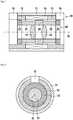
- FIG. 1schematically shows a linear motor according to the invention in a longitudinal section.
- the linear motoris predominantly rotationally symmetrical about a central axis 30. It comprises a stator 10 and a rotor 20.
- the stator 10has a coil 14, which is enclosed by a preferably cylindrical return element 11 in the radial direction. In the axial direction, the coil 14 is enclosed by a first stator pole piece 12 and a second stator pole piece 13. These stator pole shoes are also preferably enclosed in the radial direction by the return element. Furthermore, a first field sensor 15 on the side of the first Statorpolschuhs 12 in the axial direction adjacent to the coil and a second field sensor 16 on the side of the second Statorpolschuhs 13 in the axial direction adjacent to the coil 14 is arranged. At least one field sensor is preferably arranged in a section of a stator pole shoe.
- the cutoutextends as in this Figur shown, in the axial direction, but it may also extend in the radial direction.
- the cutoutcan also be continued up to the return element 11 in order to provide sufficient installation space for a larger field sensor.
- the stator pole shoes and / or the return elementare preferably ring-shaped.
- the rotorhas a first permanent magnet 21 and a second permanent magnet 22, which are polarized in the opposite direction. Between the two permanent magnets, a middle rotor pole piece 24 is arranged. A first outer rotor pole piece 23 and a second outer rotor pole shoe 25 are arranged toward the first permanent magnet 21 at the sides opposite the middle rotor pole piece 24 in the axial direction.
- the rotoris preferably hollow, more preferably designed as a hollow cylinder.
- the permanent magnets and / or the rotor pole shoesare annular.
- the two field sensors 15, 16are arranged in the same plane passing through the central axis 30 cutting plane, but they can also be arranged in other planes.
- the driveis preferably designed so that no axially directed reluctance forces prevail in the travel path of the rotor 10 in the de-energized state. If the coil 14 of the drive is supplied with an electric current, a Lorentz force is generated, which acts on the rotor regardless of its position.
- this embodimentas well as the other embodiments presented in this document can be realized with an ironless stator.
- the Statorpol notes 12, 13 and the return element 11would consist of non-ferromagnetic material or even eliminated. Due to the lack of magnetic field conductive materials in the stator is the magnetic Flux density in the magnetic circuit is lower. Thus, the driving Lorentz force is reduced by an electric current flow in the coil.
- FIG. 2a view is shown in the direction of the central axis 30.
- the preferred concentric arrangement of the componentsis clearly visible.
- the first field sensor 15is arranged in a cutout which passes through the return element 11 into the first stator pole shoe 12.
- FIGS. 3, 4 and 5show the magnetic field characteristics at different positions of the rotor 20 relative to the stator 10.
- FIG. 3is the rotor 20 with respect to the center position, which in the FIG. 4 is shown, moved to the left while in the FIG. 5 moved to the right.
- a first magnetic circuit 41results from the first permanent magnet 21.
- the fieldcontinues through the first outer rotor pole shoe 23 via the first field sensor 15 or the first stator pole shoe 12 through the return element 11, via the coil 14 into the middle rotor pole shoe 24 and back to the first permanent magnet 21.
- the second magnetic circuit 42extends in the reverse direction.
- the lines 41 and 42are shown symbolically.
- the magnetic fieldis distributed, for example, over the entire end face of the permanent magnets 21, 22.
- the magnetic field in the radial directionemerges from the rotor pole shoes distributed over the surface.
- FIG. 4occurs a part of the magnetic field from the first rotor pole piece 23 via the first field sensor 15 and parallel thereto via the first stator pole 12 in the return element 11 a.
- the fieldis divided between the second field sensor 16 and the second stator pole piece 13.
- the statorhas only one stator pole piece 12, and the rotor has only one permanent magnet 21.
- a first field sensor 17 and optionally a second field sensor 18are provided.
- Integrated field sensors 17, 18 with a smaller designare preferably used here, which can be integrated into the first stator pole shoe 12. These are preferably inserted into a recess of the first stator pole shoe 12.
- the field sensors 17, 18are offset from each other in the axial direction. They can preferably also be arranged on different cutting planes through the axis of rotation. In the embodiment shown here they are arranged in the same plane, on different sides of the axis of rotation.
- the magnetic fluxpasses from the first outer rotor pole piece 23 through one of the field sensors. In the illustrated position, a greater portion of the magnetic flux passes through the second field sensor 18 while the first field sensor is in the field-free space.
- the magnetic field sensorcan only be in the magnetic field of a pole piece.
- simpler magnetic field sensorscan be used, which provide an output signal independent of the direction of the magnetic field.
- sensorsare for example GMR (Giant Magneto Resistance) sensors.
- GMRGate Magneto Resistance
- Such sensorsare usually larger, more expensive and require a more complex control or evaluation.
- the integration of the magnetic field sensors in the stator poleallows a much better space utilization especially for miniature motors.
- This embodimentis also more robust because the magnetic field sensors are mechanically protected by the stator pole piece. This makes it possible to dispense with a separate housing of the magnetic field sensors.
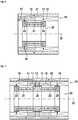
- FIG. 7a further embodiment according to the invention is shown.
- the rotor 20corresponds to the rotor of the first embodiment, as for example in the FIG. 1 is shown.
- the statorhas a first coil 14 and a second coil 19.
- the coilscan be single-phase (identical current) or two-phase (different currents in the two coils) be supplied.
- a stator pole 12is arranged between the two coils.
- the coils and the stator pole pieceare enclosed by the return element 11.
- the field sensors 17, 18are offset from each other in the axial direction in the stator pole 12 or incorporated into recesses of the stator pole.
- the magnetic field from the middle rotor pole piece 24runs wholly or partially through the first field sensor 17 or the second field sensor 18.
- the output signals of the field sensors 17, 18also approximately correspond to the curves 61 and 62 in FIG. 8 , Again, by a difference formation, a signal corresponding to FIG. 9 be achieved.
- the FIG. 8shows the waveform of the field sensors, for example, according to the representations of the FIGS. 3, 4 and 5 .
- the diagramshows on the horizontal axis the distance in millimeters relative to the zero position "0", which for example the FIG. 4 equivalent.
- a deflection of -2 mmcorresponds to the FIG. 3 and a deflection of +2 mm corresponds to FIG. 5 .
- the amplitudes of the sensor signalsare scaled from 0-150.
- the curve 61shows the signal of the first field sensor 15, while the curve 62 shows the course of the signal of the second field sensor 16.
- the curve 61shows on the left, with a deflection of -2 mm, the maximum amplitude, which corresponds to the maximum magnetic flux density by the first field sensor 15. This will be at the in FIG. 3 reached shown position of the runner. At the same time, the second field sensor 16 is in almost field-free space, so that the sensor signals corresponding to the curve 62 is almost zero. In the middle position according to the FIG. 4 the flux density is approximately the same for both field sensors, so that the two curves 61 and 62 at the position "0" have the same amplitude. In the right position at +2 mm, the sensor signals behave in the opposite way as in the left position. Here goes the maximum magnetic flux density through the second field sensor 16, while the first field sensor 15 is in almost field-free space.
- FIG. 9shows the sum of the curves 61 and 62 from the FIG. 8 in the curve 63.
- This curvecan be approximated well by a linear approximation 64. This results in a measurement signal which is proportional to the position of the rotor with slight deviations.
- This measurement signalcan also be fed into a control loop, so that the position of the rotor can be kept constant as a function of a desired value.
- the FIG. 10shows the signals of the field sensors in an arrangement according to the FIG. 6 , Again, the horizontal axis indicates the displacement in the direction of the central axis, while the vertical axis indicates the amplitude of the sensor signals.
- the curve 65indicates the signal amplitude of the first field sensor 17, while the second curve 66 indicates the amplitude of the second field sensor 18.
- the exact positioncan be determined by evaluating which sensor emits a signal in combination with the signal amplitude of the sensor. In this example only two sensors are shown. Of course, any higher number of field sensors can be used here in order to increase the resolution and / or the maximum path length.
- FIG. 11shows an endoscope 80, in which a linear motor 84 is used according to the invention for adjusting the viewing angle ⁇ .
- the endoscopehas a distal shaft 81 and a proximal eyepiece 83.
- Optional ports 82may be provided for supplying light or for supplying liquids and / or gases.
- the endoscopehas an axis 88, which is preferably also the optical and / or mechanical axis.
- a prism 85is pivotally mounted about a bearing 86. The prism allows a deflection of the optical beam path, so that at different angles ⁇ entering the distal end of the endoscope Light can be detected.
- An adjustment of the prismby means of a linear motor 84 via a push / pull rod 87th
Landscapes
- Engineering & Computer Science (AREA)
- Life Sciences & Earth Sciences (AREA)
- Health & Medical Sciences (AREA)
- Physics & Mathematics (AREA)
- Surgery (AREA)
- Power Engineering (AREA)
- Electromagnetism (AREA)
- Radiology & Medical Imaging (AREA)
- Public Health (AREA)
- Nuclear Medicine, Radiotherapy & Molecular Imaging (AREA)
- Optics & Photonics (AREA)
- Pathology (AREA)
- Veterinary Medicine (AREA)
- Biophysics (AREA)
- Biomedical Technology (AREA)
- Heart & Thoracic Surgery (AREA)
- Medical Informatics (AREA)
- Molecular Biology (AREA)
- Animal Behavior & Ethology (AREA)
- General Health & Medical Sciences (AREA)
- Chemical & Material Sciences (AREA)
- Combustion & Propulsion (AREA)
- Microelectronics & Electronic Packaging (AREA)
- Signal Processing (AREA)
- Linear Motors (AREA)
- Reciprocating, Oscillating Or Vibrating Motors (AREA)
Description
Translated fromGermanDie Erfindung betrifft einen Linearmotor insbesondere für optische Systeme. Derartige optische Systeme werden beispielsweise in Endoskopen eingesetzt. Bei modernen Videoendoskopen sind ein Kamerachip sowie ein zugehöriges Linsensystem in die Endoskopspitze integriert. Zur Einstellung der Brennweite bzw. des Fokus des Linsensystems wird ein miniaturisierter Motor benötigt.The invention relates to a linear motor, in particular for optical systems. Such optical systems are used for example in endoscopes. In modern video endoscopes, a camera chip and an associated lens system are integrated into the endoscope tip. To set the focal length or the focus of the lens system, a miniaturized motor is needed.
Klassische Endoskope, wie sie beispielsweise für die minimalinvasive Chirurgie eingesetzt werden können, führen das Bild mittels Stablinsen vom intrakorporalen Objektiv zum extrakorporalen Okular. Durch die Stablinsen ist das System starr und in der optischen Qualität begrenzt. Moderne Videoendoskope verwenden einen Kamerachip in der Endoskopspitze. Ein solches Endoskop ist in der
In der
Aus der
In der
Diese drei Linearantriebe umfassen einen Stator und einen Läufer. Die Läufer sind jeweils aus einem oder mehreren Permanentmagneten aufgebaut. Zur Umlenkung und zum Erzeugen des magnetischen Flusses in definierte Richtungen befinden sich an den Permanentmagneten Ringe aus Weicheisen (Polschuhe). Im Stator erzeugen eine oder mehrere Spulen Lorentzkräfte. Teilweise dienen zusätzliche Permanentmagnete und Ringe aus Weicheisen der Erzeugung von Reluktanzkräften. Umschlossen wird der Stator durch eine weichmagnetische Hülse, die das Rückflussjoch für den magnetischen Fluss darstellt. Im stromlosen Zustand befindet sich der Läufer aufgrund von rücktreibenden Reluktanzkräften in einer so genannten Ruheposition. Durch die Speisung der Spulen mit einem elektrischen Strom fester Stromstärke entstehen Lorentzkräfte, die zu einer kontinuierlichen Auslenkung des Läufers aus der Ruheposition führen. Durch das Einstellen eines Kräftegleichgewichts aus Lorentzkräften in der
Von außen einwirkende, schwer kontrollierbare Widerstandskräfte, wie beispielsweise die Reibungskraft oder die Schwerkraft, führen zur Positionierungenauigkeit. Durch die Vorgabe fester Stromstärken lässt sich demnach die Position des Läufers nur bedingt festlegen.Externally applied, hard-to-control resistance forces, such as frictional force or gravity, result in positioning inaccuracy. By specifying fixed currents, the position of the rotor can only be determined to a limited extent.
Die
In der
Der Erfindung liegt die Aufgabe zugrunde, einen Linearmotor dahingehend zu verbessern, dass der Läufer in definierte Positionen gebracht werden kann bzw. eine definierte und vorzugsweise eine lineare Kennlinie zwischen einem Steuersignal und einer Läuferposition besteht. Weiterhin soll bevorzugt die Position des Läufers in weiten Grenzen unabhängig von einer äußeren Last sein. Der Linearmotor soll soweit miniaturisierbar sein, dass er in ein Endoskop integrierbar ist.The invention has for its object to improve a linear motor to the effect that the rotor can be brought into defined positions or a defined and preferably a linear characteristic between a control signal and a rotor position consists. Furthermore, the position of the rotor should preferably be independent of an external load within wide limits. The linear motor should be miniaturized so far that it can be integrated into an endoscope.
Diese Aufgabe wird durch eine Vorrichtung nach einem der unabhängigen Ansprüche gelöst. Vorteilhafte Ausgestaltungen der Erfindung sind in den Unteransprüchen angegeben.This object is achieved by a device according to one of the independent claims. Advantageous embodiments of the invention are specified in the subclaims.
Der erfindungsgemäße Linearmotor umfasst einen Stator sowie einen dazu linear verschiebbaren Läufer. Bevorzugt ist der Linearmotor weitgehend rotationssymmetrisch aufgebaut. Dabei sind die Komponenten weitgehend ringförmig ausgeführt. Die Bewegung des Läufers erfolgt bevorzugt entlang einer Achse, welche bevorzugt parallel zur Mittelachse der rotationssymmetrischen Anordnung liegt und besonders bevorzugt mit dieser identisch ist. Der Stator hat eine oder zwei Spulen, wobei bevorzugt in axialer Richtung seitlich zu den Spulen wenigstens ein Statorpolschuh, sowie in radialer Richtung an der Außenseite ein Rückschlußelement, welches zumindest weitgehend parallel zur Bewegungsrichtung angeordnet ist und bevorzugt die eine oder zwei Spulen und besonders bevorzugt wenigstens einen Statorpolschuh umschließt. Der Läufer wird in radialer Richtung zumindest teilweise von der Spule umschlossen und hat einen ersten Permanentmagneten sowie optional einen zweiten Permanentmagneten. Bevorzugt ist seitlich in axialer Richtung an den Permanentmagneten jeweils ein Läuferpolschuh angeordnet. Es ist im Falle von zwei Permanentmagneten zwischen den beiden Permanentmagneten bevorzugt noch ein Polschuh angeordnet. Die Läuferpolschuhe ermöglichen einen definierten Austritt der Magnetfelder der Permanentmagnete durch die Spule in Richtung des Rückschlußelements. Grundsätzlich arbeitet die Anordnung auch ohne Polschuhe. Durch die Polschuhe kann jedoch die Kraft des Motors um mehr als eine Größenordnung erhöht werden. Im Falle von zwei Permanentmagneten, sind diese axial magnetisiert und mit ihrer Polung so ausgerichtet, dass sich wahlweise die Nordpole oder die Südpole gegenüber liegen. Der Läufer und insbesondere die Permanentmagnete sowie die Polschuhe sind bevorzugt hohlzylindrisch, d.h. sie haben die Form einer zylindrischen Hülse. Der Strahlengang eines optischen Systems kann dann durch die Hülse verlaufen. Insbesondere kann eine Linse oder ein anderes optisches Element in der Hülse sitzen. Somit kann durch eine Verschiebung der Hülse die Brennweite und/oder auch der Fokus des optischen Systems eingestellt werden.The linear motor according to the invention comprises a stator and a linearly displaceable rotor. Preferably, the linear motor is constructed largely rotationally symmetrical. The components are carried out largely annular. The movement of the rotor is preferably along an axis, which is preferably parallel to the central axis of the rotationally symmetrical arrangement and is particularly preferably identical to this. The stator has one or two coils, wherein preferably in the axial direction laterally to the coils at least a Statorpolschuh, as well as in the radial direction on the outside of a return element, which is arranged at least substantially parallel to the direction of movement and preferably encloses the one or two coils and more preferably at least one Statorpolschuh. The rotor is at least partially enclosed in the radial direction by the coil and has a first permanent magnet and optionally a second permanent magnet. Preferably, a rotor pole piece is arranged laterally in the axial direction on the permanent magnet. It is in the case of two permanent magnets between the two permanent magnets preferably still arranged a pole piece. The rotor pole pieces allow a defined exit of the magnetic fields of the permanent magnets through the coil in the direction of the return element. Basically, the arrangement works without pole pieces. The pole pieces, however, the power of the engine can be increased by more than an order of magnitude. In the case of two permanent magnets, these are axially magnetized and aligned with their polarity so that either the north pole or the south poles are opposite. The rotor and in particular the permanent magnets and the pole shoes are preferably hollow cylindrical, ie they have the shape of a cylindrical sleeve. The beam path of an optical system can then pass through the sleeve. In particular, a lens or other optical element may be seated in the sleeve. Thus, the focal length and / or the focus of the optical system can be adjusted by a displacement of the sleeve.
Die Polschuhe und das Rückschlußelement umfassen bevorzugt ferromagnetische und/oder weichmagnetische Materialien.The pole pieces and the return element preferably comprise ferromagnetic and / or soft magnetic materials.
Der Linearmotor ist bis zu einer Größe von wenigen Millimetern Außendurchmesser problemlos miniaturisierbar.The linear motor can be easily miniaturized up to a size of a few millimeters outside diameter.
Die Spule kann wahlweise auf einen Spulenkörper oder auch ohne Spulenkörper gewickelt sein. Sie kann auch mehrteilig sein, d.h. aus mehreren Wicklungen bestehen.The coil may optionally be wound on a bobbin or without bobbin. It can also be multi-part, i. consist of several windings.
Zur mittelbaren Bestimmung der Position des Läufers sind ein oder zwei Magnetfeldsensoren, hier auch Feldsensoren genannt, vorgesehen. Grundsätzlich kann auch eine höhere Anzahl von Feldsensoren eingesetzt werden. Die Magnetfeldsensoren sind seitlich in axialer Richtung neben der wenigstens einen Wicklung angeordnet. Durch diese Magnetfeldsensoren verläuft in Abhängigkeit von der Position des Läufers ein Anteil des magnetischen Flusses durch die Permanentmagnete. Über die Bestimmung des magnetischen Flusses bzw. der entsprechenden magnetischen Flussdichte B kann auf die Position des Läufers rückgeschlossen werden. Durch einphasige Bestromung der Spulen lässt sich die Ansteuerungselektronik unkompliziert realisieren. Der einfache Aufbau ermöglicht die Miniaturisierung des Antriebs, so dass er sich für den Einsatz in minimalinvasiven Instrumenten eignet. Bevorzugt ist der wenigstens eine Magnetfeldsensor seitlich neben wenigstens einem Statorpolschuh angeordnet. Alternativ kann auch wenigstens ein Magnetfeldsensor in einen Statorpolschuh integriert sein. Besonders vorteilhaft ist die Auswertung der Signaldifferenz von wenigstens zwei Magnetfeldsensoren. Dadurch kann eine stärkere Unabhängigkeit von äußeren Einflüssen wie beispielsweise der Temperatur sowie eine größere Messgenauigkeit erreicht werden.For indirect determination of the position of the rotor one or two magnetic field sensors, also called field sensors, are provided. In principle, a higher number of field sensors can also be used. The magnetic field sensors are arranged laterally in the axial direction next to the at least one winding. By means of these magnetic field sensors, depending on the position of the rotor, a portion of the magnetic flux passes through the permanent magnets. On the determination of the magnetic flux or the corresponding magnetic flux density B can be deduced the position of the rotor. By single-phase current supply of the coils, the control electronics can be implemented easily. The simple design allows for miniaturization of the drive, making it suitable for use in minimally invasive instruments. Preferably, the at least one magnetic field sensor is arranged laterally next to at least one stator pole shoe. Alternatively, at least one magnetic field sensor can also be integrated into a stator pole shoe. Particularly advantageous is the evaluation of the signal difference of at least two magnetic field sensors. As a result, a greater independence from external influences such as the temperature and a greater accuracy of measurement can be achieved.
Die bevorzugte Ausführungsform hat eine Spule und auf beiden Seiten in axialer Richtung Statorpolschuhe, wobei die Spule und die Statorpolschuhe von einem Rückschlusselement umschlossen sind. Seitlich neben den Statorpolschuh bzw. in die Statorpolschuhe integriert sind zwei Magnetfeldsensoren vorgesehen. Der Läufer hat zwei in entgegengesetzter Richtung polarisierte Permanentmagnete, wobei zwischen den beiden Permanentmagneten ein Läuferpolschuh und an den Enden der Permanentmagnete zwei weitere Läuferpolschuhe vorgesehen sind.The preferred embodiment has a coil and on both sides in the axial direction Statorpolschuhe, wherein the coil and the Statorpolschuhe are enclosed by a return element. Two magnetic field sensors are provided laterally next to the stator pole shoe or in the stator pole shoes. The rotor has two polarized in the opposite direction permanent magnets, wherein between the two permanent magnets, a rotor pole piece and at the ends of the permanent magnets two further rotor pole pieces are provided.
Eine Variante des erfindungsgemäßen Linearmotors hat nur einen Statorpolschuh und entsprechend auch nur einen Feldsensor. Passend hierzu kann der Läufer vereinfacht mit nur einem Permanentmagneten und bevorzugt mit zwei Läuferpolschuhen an den Enden des Permanentmagneten ausgestaltet sein.A variant of the linear motor according to the invention has only one stator pole piece and correspondingly only one field sensor. In keeping with this, the rotor can be simplified with only one permanent magnet and preferably with two rotor pole shoes at the ends of the permanent magnet.
In einer weiteren Ausgestaltung der Erfindung sind zwei Spulen seitlich in axialer Richtung an zwei Seiten eines Statorpolschuhs angeordnet. Hier ist mindestens ein Magnetfeldsensor, bevorzugt zwei Magnetfeldsensoren in den Statorpolschuh integriert. Bevorzugt wird hier ein Läufer mit zwei entgegengesetzt gepolten Permanentmagneten und jeweils einem Läuferpolschuh zwischen den Permanentmagneten sowie an den äußeren Enden der Permanentmagnete eingesetzt.In a further embodiment of the invention, two coils are arranged laterally in the axial direction on two sides of a Statorpolschuhs. Here at least one magnetic field sensor, preferably two magnetic field sensors, is integrated into the stator pole shoe. Preferably, a rotor with two oppositely poled permanent magnets and one rotor pole piece between the permanent magnets and at the outer ends of the permanent magnets is used here.
Zur Magnetfeldmessung können unterschiedliche Sensortypen zum Einsatz kommen. Die gängigsten Sensoren sind Hall-Effekt-Sensoren, GMR-Sensoren und AMR-Sensoren.For measuring the magnetic field different sensor types can be used. The most common sensors are Hall effect sensors, GMR sensors and AMR sensors.
Bei dem erfindungsgemäßen Linearmotor ist kein Gleichgewichtszustand zwischen Reluktanzkraft- und Lorentzkraft für die Positionierung, wie bei den aus dem Stand der Technik bekannten Linearantrieben notwendig. Dies führt im Vergleich zu deutlich höheren Antriebs- und Stellkräften bei gleicher elektrischer Leistung. Dadurch lässt er sich auch in chirurgischen Instrumenten einsetzen.In the case of the linear motor according to the invention, no equilibrium state between reluctance force and Lorentz force is necessary for the positioning, as is the case with the linear drives known from the prior art. This results in comparison to significantly higher drive and actuating forces with the same electrical power. As a result, it can also be used in surgical instruments.
Die verschiedenen Varianten des erfindungsgemäßen Linearmotors können auch mit einem eisenlosen Stator realisiert werden. Hierbei würden dann die Statorpolschuhe sowie das Rückschlusselement aus nicht-ferromagnetischem Material bestehen oder gar entfallen. Aufgrund der fehlenden magnetfeldleitenden Materialien im Stator ist die magnetische Flussdichte im magnetischen Kreis geringer. Damit wird auch die antreibende Lorentzkraft durch einen elektrischen Stromfluss in der Spule geringer.The different variants of the linear motor according to the invention can also be realized with an ironless stator. In this case, the stator pole shoes and the return element would then consist of non-ferromagnetic material or even be omitted. Due to the lack of magnetic field conducting materials in the stator, the magnetic flux density in the magnetic circuit is lower. Thus, the driving Lorentz force is reduced by an electric current flow in the coil.
In einer weiteren vorteilhaften Ausgestaltung der Erfindung ist zwischen dem Stator und dem Läufer eine Gleitschicht. Diese kann insbesondere im Falle einer rotationssymmetrischen Anordnung als Gleithülse ausgeführt sein. Um die Magnetfelder möglichst wenig zu beeinflussen soll die Gleitschicht aus einem nicht magnetfeldführenden Material, insbesondere aus einem nicht- ferromagnetischen Material bestehen. Ihre Oberfläche umfasst bevorzugt ein Material mit niedrigem Reibungskoeffizienten, beispielsweise PTFE (Polytetrafluorethylen), Siliziumnitrid, Siliziumkarbid, Poly-para-Xylylen Polymere oder DLC (diamond like carbon) wie beispielsweise in der
Die Gleitschicht kann Unebenheiten auf der dem Läufer zugewandten Seite des Stators ausgleichen.The sliding layer can compensate for unevenness on the rotor-facing side of the stator.
Der beschriebene Linearmotor kann in einer alternativen Ausführungsform mit einem ebenen, z.B. plattenförmig aufgebauten Stator und einem ebenfalls ebenen bzw. plattenförmigen Polschuh des Läufers realisiert werden. Alternativ können auch mehrere um einen Zylinder oder einen vieleckigen Körper angeordnete Linearmotoren vorgesehen sein. So ergibt sich beispielsweise bei einer gleichmäßigen Anordnung von Linearmotoren um einen Zylinder eine stabile Führung.The described linear motor may, in an alternative embodiment, be provided with a plane, e.g. plate-shaped stator and a likewise flat or plate-shaped pole piece of the rotor can be realized. Alternatively, a plurality of linear motors arranged around a cylinder or a polygonal body may also be provided. For example, with a uniform arrangement of linear motors around a cylinder, stable guidance results.
Ein erfindungsgemäßer Linearmotor kann auch aus Vollmaterial bestehen und an einem Ende einen Stößel zur Nanopositionierung von Instrumenten aufweisen. Eine solche Vorrichtung ist bevorzugt in der Molekularbiologie, der Mikroelektronik oder auch der Neurochirurgie einsetzbar.A linear motor according to the invention can also consist of solid material and have at one end a plunger for the nanopositioning of instruments. Such a device is preferably used in molecular biology, microelectronics or neurosurgery.
Durch den einfachen Aufbau lässt sich der Antrieb in Bezug auf die axiale Baulänge sehr kompakt ausführen. Damit ist der Antrieb als Ausführung mit einem Hohlläufer für den Einsatz in optischen Systemen gut geeignet.Due to its simple design, the drive can be very compact in terms of axial length. Thus, the drive is well suited as a version with a hollow rotor for use in optical systems.
Der erfindungsgemäße Antrieb kann direkt in das Objektiv einer Endoskopkamera integriert werden. Eine geregelte Einstellung von Zoom- und Fokusfunktion mit Messung der Position der beweglichen optischen Linsengruppen ist damit möglich. Durch die kleine Bauform können nun auch platzsparend Stereokameras mit zwei Einzelobjektiven für 3D-Systeme in ein konventionelles Kameragehäuse integriert werden. Der erfindungsgemäße Linearantrieb ist bevorzugt zweimal in identischer Bauweise für die Bewegung von Linsengruppen entlang der optischen Achse integriert. Durch die geregelte Positionierung der Linsengruppen durch die Linearantriebe können die auf die Bildaufnehmer auftreffenden Bilder scharf angezeigt werden.The drive according to the invention can be integrated directly into the objective of an endoscope camera. A controlled adjustment of zoom and focus function with measurement of the position of the movable optical lens groups is thus possible. Thanks to the small design, space-saving stereo cameras with two individual lenses for 3D systems can now be integrated into a conventional camera housing. The linear drive according to the invention is preferably integrated twice in identical construction for the movement of lens groups along the optical axis. Due to the controlled positioning of the lens groups by the linear drives, the images impinging on the image sensors can be displayed sharply.
In Chip-on-the-Tip-Objektiven kann die komplette Optik einschließlich eines Kamerachips in die Spitze eines Endoskops integriert werden. Dabei werden optische Linsengruppen beispielsweise entlang der optischen Achse bewegt, um eine Scharfeinstellung (Fokussierung) oder eine Vergrößerung (Zoomfunktion) des Bilds zu ermöglichen. Der erfindungsgemäße geregelte Linearantrieb kann in miniaturisierter Form ebenfalls in Videoendoskopen zum Einsatz kommen. Durch den erfindungsgemäßen Antrieb bietet sich dabei die Möglichkeit, die Position der Linsengruppen durch Rückkopplung der Positionssignale zu regeln. Durch die Messung der Läuferposition mit den Magnetfeldsensoren ist die Position der Linsengruppen bekannt. Bei einem Antrieb für die Fokusverstellung kann damit bei Kenntnis über das optische System der Objektabstand zu scharfgestellten Objekten ermittelt werden. Mit dem erfindungsgemäßen Linearantrieb ist auch eine einfache Kopplung von zwei oder mehreren beweglichen Linsengruppen möglich. Bei Stereoendoskopen in Chip-on-the-Tip-Ausführung werden für die Paarbildaufnahme häufig zwei nebeneinander liegende optische Linsensysteme an der Endoskopspitze verwendet. Sollen hierbei jeweils Linsengruppen für eine Fokussierung oder Zoomfunktion axial motorisch beweglich sein, können zwei erfindungsgemäße Antriebe dafür eingesetzt werden.In chip-on-the-tip lenses, the complete optics including a camera chip can be integrated into the tip of an endoscope. In this case, optical lens groups are moved along the optical axis, for example, in order to enable focusing (focusing) or enlargement (zooming) of the image. The controlled linear drive according to the invention can also be used in miniaturized form in video endoscopes. The drive according to the invention offers the possibility of regulating the position of the lens groups by feedback of the position signals. By measuring the rotor position with the magnetic field sensors, the position of the lens groups is known. In the case of a drive for the focus adjustment, it is thus possible, with knowledge of the optical system, to determine the object distance to the objects in focus. With the linear drive according to the invention also a simple coupling of two or more movable lens groups is possible. In the case of stereo endoscopes in chip-on-the-tip design, two adjacent optical lens systems are often used on the endoscope tip for pair image acquisition. If in each case lens groups for a focusing or zoom function are to be axially movable by an electric motor, two drives according to the invention can be used for this purpose.
Durch den Einsatz des erfindungsgemäßen Antriebs in einem chirurgischen Instrument ist es möglich, einen Öffnungswinkel Phi eines Maulteils geregelt einzustellen. Über die Magnetfeldsensoren kann der Läufer des erfindungsgemäßen Antriebs wie oben beschrieben innerhalb des Stators positioniert werden. Wird eine Zug-Druck-Stange, die durch eine Linearbewegung das Öffnen und Schließen eines Maulteils hervorruft, an den Antrieb montiert, kann über die Position des Läufers der Öffnungswinkel des Instruments Phi eingestellt werden. Durch den geregelten Betrieb kann unabhängig von der Schließkraft des Maulteils der Öffnungswinkel Phi beibehalten oder eingestellt werden. Da es sich bei dem erfindungsgemäßen Antrieb um einen über Lorentzkraft betätigten Linearmotor handelt, kann über den Zusammenhang der Stromstärke in der Spule auch die axial wirkende Antriebskraft ermittelt werden. Dadurch kann auch die Schließkraft am Maulteil berechnet werden. Dieser Zusammenhang spielt vor allem bei neuartigen Force-Feedback-Systemen eine große Rolle, bei denen der operierende Arzt eine Rückmeldung über die Höhe der Schließkraft am Maulteil erhält.By using the drive according to the invention in a surgical instrument, it is possible to set an opening angle Phi of a jaw part regulated. About the magnetic field sensors, the rotor of the drive according to the invention can be positioned within the stator as described above. If a pull-push rod, which causes the opening and closing of a jaw part by a linear motion, is mounted on the drive, the position of the slider can be used to adjust the opening angle of the instrument Phi. Due to the controlled operation, the opening angle Phi can be maintained or adjusted independently of the closing force of the jaw part. Since the drive according to the invention is a linear motor operated by means of a Lorentz force, the axially acting driving force can also be determined via the relationship between the current intensity in the coil. As a result, the closing force on the jaw part can also be calculated. This relationship is particularly important in novel force feedback systems in which the operating physician receives feedback about the amount of closing force on the jaw part.
Die Erfindung wird nachstehend ohne Beschränkung des allgemeinen Erfindungsgedankens anhand von Ausführungsbeispielen unter Bezugnahme auf die Zeichnungen exemplarisch beschrieben.
Figur 1- zeigt schematisch einen Linearmotor entsprechend der Erfindung in einem Längsschnitt.
Figur 2- zeigt den linearen Motor in einem Querschnitt.
- Figur 3
- zeigt den magnetischen Feldverlauf in einer ersten Läuferposition.
- Figur 4
- zeigt den magnetischen Feldverlauf in einer zweiten Läuferposition.
- Figur 5
- zeigt den magnetischen Feldverlauf in einer dritten Läuferposition.
- Figur 6
- zeigt eine weitere Ausführungsform mit nur einem Statorpolschuh.
- Figur 7
- zeigt eine weitere Ausführungsform mit zwei Spulen.
- Figur 8
- zeigt die Sensorsignale einer Anordnung nach
Figur 1 in Abhängigkeit von der Position. - Figur 9
- zeigt die Differenz der Sensorsignale in Abhängigkeit von der Position.
Figur 10- zeigt die Sensorsignale in einer Anordnung nach
Figur 6 . Figur 11- zeigt ein Endoskop mit einem durch einen linearen Motor schwenkbaren Prisma.
- FIG. 1
- schematically shows a linear motor according to the invention in a longitudinal section.
- FIG. 2
- shows the linear motor in a cross section.
- FIG. 3
- shows the magnetic field profile in a first rotor position.
- FIG. 4
- shows the magnetic field course in a second rotor position.
- FIG. 5
- shows the magnetic field profile in a third rotor position.
- FIG. 6
- shows a further embodiment with only one Statorpolschuh.
- FIG. 7
- shows a further embodiment with two coils.
- FIG. 8
- shows the sensor signals of an arrangement
FIG. 1 depending on the position. - FIG. 9
- shows the difference of the sensor signals depending on the position.
- FIG. 10
- shows the sensor signals in an arrangement
FIG. 6 , - FIG. 11
- shows an endoscope with a prism pivotable by a linear motor.
Die
Der Stator 10 hat eine Spule 14, welche von einem vorzugsweise zylindrischen Rückschlusselement 11 in radialer Richtung umschlossen ist. In axialer Richtung ist die Spule 14 durch einen ersten Statorpolschuh 12 und einen zweiten Statorpolschuh 13 eingeschlossen. Bevorzugt sind auch diese Statorpolschuhe durch das Rückschlusselement in radialer Richtung umschlossen. Weiterhin ist ein erster Feldsensor 15 auf der Seite des ersten Statorpolschuhs 12 in axialer Richtung neben der Spule und ein zweiter Feldsensor 16 auf der Seite des zweiten Statorpolschuhs 13 in axialer Richtung neben der Spule 14 angeordnet. Bevorzugt ist wenigstens ein Feldsensor in einem Ausschnitt eines Statorpolschuhs angeordnet. Besonders bevorzugt erstreckt sich der Ausschnitt, wie in dieser Figur dargestellt, in axialer Richtung, er kann sich aber auch in radialer Richtung erstrecken. Der Ausschnitt kann auch bis in das Rückschlusselement 11 fortgesetzt sein, um einem größeren Feldsensor hinreichend Einbauraum zu bieten. Bevorzugt sind die Statorpolschuhe und/oder das Rückschlusselement ringförmig ausgebildet.The
Der Läufer hat einen ersten Permanentmagnet 21 und einen zweiten Permanentmagnet 22, welche in entgegengesetzter Richtung polarisiert sind. Zwischen den beiden Permanentmagneten ist ein mittlerer Läuferpolschuh 24 angeordnet. An den in axialer Richtung dem mittleren Läuferpolschuh 24 entgegengesetzten Seiten sind zum ersten Permanentmagnet 21 hin ein erster äußerer Läuferpolschuh 23 und zum zweiten Permanentmagnet 22 hin ein zweiter äußerer Läuferpolschuh 25 angeordnet. Der Läufer ist bevorzugt hohl, besonders bevorzugt hohlzylindrisch ausgeführt. Bevorzugterweise sind die Permanentmagnete und/oder die Läuferpolschuhe ringförmig ausgebildet.The rotor has a first
Bevorzugt sind die beiden Feldsensoren 15, 16 in derselben durch die Mittelachse 30 verlaufenden Schnittebene angeordnet, sie können aber auch in anderen Ebenen angeordnet sein.Preferably, the two
Der Antrieb ist bevorzugt so ausgelegt, dass innerhalb des Verfahrwegs des Läufers 10 im unbestromten Zustand keine axial gerichteten Reluktanzkräfte herrschen. Wird die Spule 14 des Antriebs mit einem elektrischen Strom versorgt, entsteht eine Lorentzkraft, die auf den Läufer unabhängig von dessen Position einwirkt.The drive is preferably designed so that no axially directed reluctance forces prevail in the travel path of the
Grundsätzlich kann diese Ausführungsform wie auch die anderen in diesem Dokument vorgestellten Ausführungsformen mit einem eisenlosen Stator realisiert werden. Hierbei würden dann die Statorpolschuhe 12, 13 sowie das Rückschlusselement 11 aus nicht-ferromagnetischem Material bestehen oder gar entfallen. Aufgrund der fehlenden magnetfeldleitenden Materialien im Stator ist die magnetische Flussdichte im magnetischen Kreis geringer. Damit wird auch die antreibende Lorentzkraft durch einen elektrischen Stromfluss in der Spule geringer.In principle, this embodiment as well as the other embodiments presented in this document can be realized with an ironless stator. Here, the
In der
Die
Zur Darstellung des magnetischen Feldverlaufs sind symbolisch die Linien 41 und 42 eingezeichnet. Tatsächlich verteilt sich das magnetische Feld beispielsweise über die gesamte Stirnfläche der Permanentmagnete 21, 22. Ebenso tritt das magnetische Feld in radialer Richtung aus den Läuferpolschuhen verteilt über die Fläche aus.To illustrate the magnetic field course, the
In der Darstellung der
In der
In der
In der
Durch die hier dargestellte Anordnung kann der Magnetfeldsensor nur im Magnetfeld eines Polschuhs liegen. Dadurch können einfachere Magnetfeldsensoren eingesetzt werden, die ein Ausgangssignal unabhängig von der Richtung des Magnetfelds liefern. Solche Sensoren sind beispielsweise GMR-(Giant Magneto Resistance) Sensoren. Beim Stand der Technik ist es oftmals notwendig, richtungssensitive Magnetfeldsensoren wie beispielsweise Hall-Sensoren einzusetzen, um eine eindeutige Positionserkennung zu erreichen. Solche Sensoren sind meist größer, teurer und erfordern eine komplexere Ansteuerung bzw. Auswertung.By the arrangement shown here, the magnetic field sensor can only be in the magnetic field of a pole piece. As a result, simpler magnetic field sensors can be used, which provide an output signal independent of the direction of the magnetic field. Such sensors are for example GMR (Giant Magneto Resistance) sensors. In the prior art, it is often necessary to use directionally sensitive magnetic field sensors such as Hall sensors in order to achieve a clear position detection. Such sensors are usually larger, more expensive and require a more complex control or evaluation.
Die Integration der Magnetfeldsensoren in den Statorpolschuh erlaubt insbesondere bei Miniaturmotoren eine wesentlich bessere Raumausnutzung. Diese Ausführungsform ist gleichzeitig robuster, da die Magnetfeldsensoren durch den Statorpolschuh mechanisch geschützt werden. Dadurch kann auf ein separates Gehäuse der Magnetfeldsensoren verzichtet werden.The integration of the magnetic field sensors in the stator pole allows a much better space utilization especially for miniature motors. This embodiment is also more robust because the magnetic field sensors are mechanically protected by the stator pole piece. This makes it possible to dispense with a separate housing of the magnetic field sensors.
Grundsätzlich kann bei dieser Ausführungsform eines Linearmotors auch eine Anordnung aus einem ersten Magnetfeldsensor 15 neben einem ersten Statorpolschuh 12 wie in der Ausführungsform nach
In der
Die
Die Kurve 61 zeigt links, bei einer Auslenkung von -2 mm die maximale Amplitude, was der maximalen magnetischen Flussdichte durch den ersten Feldsensor 15 entspricht. Diese wird bei der in
Die
Die
Die
- 1010
- Statorstator
- 1111
- RückschlußelementGround element
- 1212
- Erster StatorpolschuhFirst stator pole piece
- 1313
- Zweiter StatorpolschuhSecond stator pole piece
- 1414
- SpuleKitchen sink
- 1515
- erster Feldsensorfirst field sensor
- 1616
- zweiter Feldsensorsecond field sensor
- 1717
- erster integrierter Feldsensorfirst integrated field sensor
- 1818
- zweiter integrierter Feldsensorsecond integrated field sensor
- 1919
- Zweite SpuleSecond coil
- 2020
- Läuferrunner
- 2121
- erster Permanentmagnetfirst permanent magnet
- 2222
- zweiter Permanentmagnetsecond permanent magnet
- 2323
- erster Läuferpolschuhfirst runner pole piece
- 2424
- zweiter Läuferpolschuhsecond runner pole piece
- 2525
- dritter Läuferpolschuhthird runner pole piece
- 3030
- Mittelachsecentral axis
- 4141
- erster Feldverlauffirst field course
- 4242
- zweiter Feldverlaufsecond field course
- 5151
- erste Linsefirst lens
- 5252
- zweite Linsesecond lens
- 6161
- Signalverlauf erster FeldsensorSignal waveform first field sensor
- 6262
- Signalverlauf zweiter FeldsensorSignal waveform second field sensor
- 6363
- Differenz der SignalverläufeDifference of the signal curves
- 6464
- lineare Approximationlinear approximation
- 6565
- Signalverlauf erster integrierter FeldsensorWaveform first integrated field sensor
- 6666
- Signalverlauf zweiter integrierter FeldsensorSignal waveform second integrated field sensor
- 8080
- Endoskopendoscope
- 8181
- Endoskopschaftendoscope shaft
- 8282
- Anschlussconnection
- 8383
- Okulareyepiece
- 8484
- Linearmotorlinear motor
- 8585
- Prismaprism
- 8686
- Lagercamp
- 8787
- Schub/ZugstangePush / pull rod
- 8888
- Mittelachsecentral axis
Claims (14)
- Linear motor comprising
a stator (10) having a middle axis (30), a coil (14) which is enclosed in the axial direction to the middle axis (30) at two sides by a first annular stator pole shoe (12) and a second annular stator pole shoe (13), a magnetic circuit closing element (11) which encloses the coil (14) in a radial direction, as well as a first field sensor (15) arranged in the axial direction next to the coil (14) at the side of the first stator pole shoe (12) and a second field sensor (16) arranged in the axial direction next to the coil (14) at the side of the second stator pole shoe (13), and
a hollow rotor (20) being displaceable in the axial direction in the stator, the rotor comprising a first annular permanent magnet (21) and a second annular permanent magnet (22) which are polarized in opposite directions, an annular middle rotor pole shoe (24) between the two permanent magnets as well as an annular first outer rotor pole shoe (23) at the side of the first permanent magnet (21) opposite in the axial direction to the middle rotor pole shoe (24) and an annular second outer rotor pole shoe (25) at a side of the second permanent magnet (22) opposite in the axial direction to the middle rotor pole shoe (24),
wherein at least a portion of the magnetic flow from the first outer rotor pole shoe (23) and/or the second outer rotor pole shoe (25) flows through at least one of the field sensors (15, 16). - Linear motor comprising
a stator (10) having a middle axis (30), a coil (14) which is enclosed in the axial direction to the middle axis (30) at one side by an annular stator pole shoe (12), a magnetic circuit closing element (11) which encloses the coil (14) in a radial direction, as well as a field sensor (17) integrated into the stator pole shoe (12), and
a hollow rotor (20) being displaceable in the axial direction in the stator, the rotor comprising a first annular permanent magnet (21) as well as an annular first outer rotor pole shoe (23) and an annular second outer rotor pole shoe (24) at the axially opposed sides of the permanent magnet (21),
wherein at least a portion of the magnetic flow from the first outer rotor pole shoe (23) flows through the field sensor (17). - Linear motor according to claim 2,characterized in that a second field sensor (18) is integrated into the stator pole shoe (12) and is displaced in the axial direction in relation to the first field sensor (17).
- Linear motor comprising
a stator (10) having a middle axis (30), a first coil (14), a second coil (19), a first annular stator pole shoe (12) between the two coils (14, 19), a magnetic circuit closing element (11) which encloses the coils (14, 19) in a radial direction, as well as a first field sensor (17) and a second field sensor (18), wherein both field sensors (17, 18) are integrated into the stator pole shoe (12) and are displaced in an axial direction to the middle axis (30) in relation to one another, and
a hollow rotor (20) being displaceable in the axial direction in the stator, the rotor comprising a first annular permanent magnet (21) and a second annular permanent magnet (22) which are polarized in opposite directions, an annular middle rotor pole shoe (24) between the two permanent magnets, as well as an annular first outer rotor pole shoe (23) at the side of the first permanent magnet (21) opposite in the axial direction to the middle rotor pole shoe (24), and an annular second outer rotor pole shoe (25) at a side of the second permanent magnet (22) opposite in the axial direction to the middle rotor pole shoe (24),
wherein at least a portion of the magnetic flow from the middle rotor pole shoe (24) flows through at least one of the field sensors (17, 18). - Linear motor according to any preceding claim,characterized in that an at least one of the field sensors (15, 16, 17, 18) is arranged in a cavity of the corresponding stator pole shoe (12, 13) or is integrated into the stator pole shoe.
- Linear motor according to claim 1, 3 or 4,characterized in that an evaluation circuitry is provided which generates a signal to indicate the position of the rotor using the sum of the signals of both field sensors (15, 16 or 17, 18).
- Linear motor according to any preceding claim,characterized in that a control circuitry is provided which compares a target value for a position of the rotor to a measurement value of at least one signal of at least one field sensor and generates a setting signal to keep the position of the rotor constant.
- Linear motor according to any preceding claim,characterized in that at least one of the field sensors (15, 16) is enclosed in the radial direction by the magnetic circuit closing element (11).
- Linear motor according to any preceding claim,characterized in that at least one stator pole shoe (12, 13) and/or at least one rotor pole shoe (23, 24, 25) and/or the magnetic circuit closing element (11) comprise at least one ferromagnetic material.
- Linear motor according to any preceding claim,characterized in that on the inside of the rotor (20) an optical element (51, 52) may be received.
- Linear motor according to any preceding claim,characterized in that a slide sleeve comprising a non-ferromagnetic material with a low coefficient of friction is arranged at the surface between stator (10) and rotor (20).
- Camera comprising a linear motor according to any preceding claim,characterized in that the linear motor is provided for controlling at least one optical component.
- Endoscope comprising a linear motor according to any preceding claim,characterized in that the linear motor is provided for the control of at least one optical component.
- Medical instrument according to any preceding claim,characterized in that the linear motor is provided for setting the opening angle of a jaw element.
Applications Claiming Priority (1)
| Application Number | Priority Date | Filing Date | Title |
|---|---|---|---|
| DE102014107297.9ADE102014107297A1 (en) | 2014-05-23 | 2014-05-23 | Position controlled electrodynamic linear drive |
Publications (3)
| Publication Number | Publication Date |
|---|---|
| EP2947756A2 EP2947756A2 (en) | 2015-11-25 |
| EP2947756A3 EP2947756A3 (en) | 2016-01-06 |
| EP2947756B1true EP2947756B1 (en) | 2017-07-19 |
Family
ID=53191579
Family Applications (1)
| Application Number | Title | Priority Date | Filing Date |
|---|---|---|---|
| EP15168992.4AActiveEP2947756B1 (en) | 2014-05-23 | 2015-05-22 | Position controlled electrodynamic linear motor |
Country Status (3)
| Country | Link |
|---|---|
| US (1) | US9722480B2 (en) |
| EP (1) | EP2947756B1 (en) |
| DE (1) | DE102014107297A1 (en) |
Families Citing this family (7)
| Publication number | Priority date | Publication date | Assignee | Title |
|---|---|---|---|---|
| CN107615126B (en)* | 2015-06-02 | 2020-05-26 | 奥林巴斯株式会社 | Optical unit and endoscope |
| DE102017107414A1 (en)* | 2017-04-06 | 2018-10-11 | Olympus Winter & Ibe Gmbh | Stereoscopic optical system of a surgical instrument and method of making the same |
| WO2019123730A1 (en) | 2017-12-22 | 2019-06-27 | オリンパス株式会社 | Endoscope optical unit and endoscope |
| WO2019146144A1 (en) | 2018-01-25 | 2019-08-01 | オリンパス株式会社 | Optical unit and endoscope |
| WO2021119847A1 (en)* | 2019-12-19 | 2021-06-24 | The University Of British Columbia | Micromotor-integrated endoscopic side-viewing probe |
| FR3138858B1 (en)* | 2022-08-09 | 2025-07-18 | Safran Electronics & Defense | Linear motor, load orientation device comprising such a motor and a gyro-stabilized module equipped with such a motor |
| JP7599019B1 (en)* | 2022-12-19 | 2024-12-12 | エーエーシー テクノロジーズ (ナンジン) カンパニーリミテッド | Multi-directional vibration motor |
Family Cites Families (16)
| Publication number | Priority date | Publication date | Assignee | Title |
|---|---|---|---|---|
| US4318038A (en)* | 1978-11-15 | 1982-03-02 | Nippon Electric Co., Ltd. | Moving-coil linear motor |
| US5411797A (en) | 1988-04-18 | 1995-05-02 | Board Of Regents, The University Of Texas System | Nanophase diamond films |
| DE4012832C2 (en) | 1990-04-23 | 1995-03-09 | Festo Kg | magnetic valve |
| TW243568B (en) | 1993-11-16 | 1995-03-21 | At & T Corp | Digital signal processor with an embedded viterbi co-processor |
| DE19605413A1 (en) | 1996-02-14 | 1996-07-11 | Schinkoethe Wolfgang Prof Dr I | DC linear motor for use in position control |
| JPH09275694A (en) | 1996-04-02 | 1997-10-21 | Minolta Co Ltd | Energizing circuit for armature coil of linear motor |
| JP2000092809A (en)* | 1998-09-10 | 2000-03-31 | Efutemu:Kk | Linear dc motor having position detecting function |
| JP2000210251A (en) | 1999-01-21 | 2000-08-02 | Olympus Optical Co Ltd | Endoscope unit |
| EP1365208A4 (en)* | 2000-12-27 | 2007-03-14 | Bridgestone Corp | Displacement sensor |
| DE10323629A1 (en) | 2003-03-24 | 2004-10-14 | Technische Universität Berlin | Traveling wave linear motor |
| US20070097532A1 (en)* | 2005-11-03 | 2007-05-03 | Industrial Technology Research Institute | Optical devices |
| CN201063067Y (en)* | 2007-06-18 | 2008-05-21 | 华宏新技股份有限公司 | Lens actuating device |
| DE102008038926A1 (en)* | 2007-08-16 | 2009-02-19 | Vizaar Ag | Electromagnetic linear motor |
| US20110170288A1 (en) | 2010-01-11 | 2011-07-14 | Led Folio Corporation | Led retrofit unit having adjustable heads for street lighting |
| DE102010000582A1 (en) | 2010-02-26 | 2011-09-01 | Karl Storz Gmbh & Co. Kg | Linear motor with permanent magnetic latching |
| JP2012090467A (en)* | 2010-10-21 | 2012-05-10 | Seiko Epson Corp | Linear motor |
- 2014
- 2014-05-23DEDE102014107297.9Apatent/DE102014107297A1/ennot_activeWithdrawn
- 2015
- 2015-05-22EPEP15168992.4Apatent/EP2947756B1/enactiveActive
- 2015-05-23USUS14/720,779patent/US9722480B2/enactiveActive
Non-Patent Citations (1)
| Title |
|---|
| None* |
Also Published As
| Publication number | Publication date |
|---|---|
| DE102014107297A1 (en) | 2015-11-26 |
| US20150340939A1 (en) | 2015-11-26 |
| EP2947756A2 (en) | 2015-11-25 |
| EP2947756A3 (en) | 2016-01-06 |
| US9722480B2 (en) | 2017-08-01 |
Similar Documents
| Publication | Publication Date | Title |
|---|---|---|
| EP2947756B1 (en) | Position controlled electrodynamic linear motor | |
| EP2362530B1 (en) | Linear motor with permanent magnetic lock | |
| EP2362529B1 (en) | Linear drive powered by reluctance and Lorentz force | |
| EP2591480B1 (en) | Electromagnetic actuator for a surgical instrument | |
| EP2175458B1 (en) | Linear motor for positioning optical systems | |
| EP1609233B1 (en) | Gliding field linear motor | |
| DE19718189C2 (en) | Device for changing the position of an optical imaging system | |
| EP2365617A2 (en) | Electromagnetic linear step motor | |
| DE102012224179A1 (en) | Electromagnetic actuator for a surgical instrument | |
| EP2034594A2 (en) | Electromagnetic linear motor | |
| DE102014103169A1 (en) | Optical device and optical system | |
| EP2954542B1 (en) | Bi-stable electromagnetic actuator, and surgical instrument | |
| DE112015006490T5 (en) | Optical unit and endoscope | |
| DE19618355A1 (en) | Endoscope with distal arranged lens | |
| DE10323629A1 (en) | Traveling wave linear motor | |
| DE102012204841B4 (en) | Rotary anode X-ray and X-ray system | |
| WO2018099783A1 (en) | Electromagnetic actuator for a surgical instrument | |
| EP3606397B1 (en) | Stereoscopic optical system of a surgical instrument and method for producing same | |
| DE102011089055A1 (en) | Instrument e.g. medical instrument e.g. endoscope for e.g. medical investigation, has actuator that is provided to adjust adjusting element along longitudinal axis of runner relative to stator and is designed as reluctance motor | |
| WO2019137789A1 (en) | Endoscope | |
| EP1971890B1 (en) | Method for operating an optical system and optical system | |
| DE102010030007A1 (en) | Magnetic resonance-compliant microscope for use in operating microscope system, has actuator for controlling adjustable mechanism of microscope and formed as electroactive polymer actuator | |
| DE19610720A1 (en) | Focus adjustment arrangement for slide projector |
Legal Events
| Date | Code | Title | Description |
|---|---|---|---|
| PUAI | Public reference made under article 153(3) epc to a published international application that has entered the european phase | Free format text:ORIGINAL CODE: 0009012 | |
| AK | Designated contracting states | Kind code of ref document:A2 Designated state(s):AL AT BE BG CH CY CZ DE DK EE ES FI FR GB GR HR HU IE IS IT LI LT LU LV MC MK MT NL NO PL PT RO RS SE SI SK SM TR | |
| AX | Request for extension of the european patent | Extension state:BA ME | |
| PUAL | Search report despatched | Free format text:ORIGINAL CODE: 0009013 | |
| AK | Designated contracting states | Kind code of ref document:A3 Designated state(s):AL AT BE BG CH CY CZ DE DK EE ES FI FR GB GR HR HU IE IS IT LI LT LU LV MC MK MT NL NO PL PT RO RS SE SI SK SM TR | |
| AX | Request for extension of the european patent | Extension state:BA ME | |
| RIC1 | Information provided on ipc code assigned before grant | Ipc:H02K 11/00 20160101AFI20151130BHEP Ipc:H02K 41/035 20060101ALI20151130BHEP | |
| 17P | Request for examination filed | Effective date:20160706 | |
| RBV | Designated contracting states (corrected) | Designated state(s):AL AT BE BG CH CY CZ DE DK EE ES FI FR GB GR HR HU IE IS IT LI LT LU LV MC MK MT NL NO PL PT RO RS SE SI SK SM TR | |
| REG | Reference to a national code | Ref country code:DE Ref legal event code:R079 Ref document number:502015001460 Country of ref document:DE Free format text:PREVIOUS MAIN CLASS: H02K0011000000 Ipc:H02K0011215000 | |
| GRAP | Despatch of communication of intention to grant a patent | Free format text:ORIGINAL CODE: EPIDOSNIGR1 | |
| STAA | Information on the status of an ep patent application or granted ep patent | Free format text:STATUS: GRANT OF PATENT IS INTENDED | |
| RIC1 | Information provided on ipc code assigned before grant | Ipc:H02K 11/215 20160101AFI20170127BHEP Ipc:H02K 41/035 20060101ALI20170127BHEP | |
| INTG | Intention to grant announced | Effective date:20170303 | |
| GRAS | Grant fee paid | Free format text:ORIGINAL CODE: EPIDOSNIGR3 | |
| GRAA | (expected) grant | Free format text:ORIGINAL CODE: 0009210 | |
| STAA | Information on the status of an ep patent application or granted ep patent | Free format text:STATUS: THE PATENT HAS BEEN GRANTED | |
| AK | Designated contracting states | Kind code of ref document:B1 Designated state(s):AL AT BE BG CH CY CZ DE DK EE ES FI FR GB GR HR HU IE IS IT LI LT LU LV MC MK MT NL NO PL PT RO RS SE SI SK SM TR | |
| REG | Reference to a national code | Ref country code:GB Ref legal event code:FG4D Free format text:NOT ENGLISH | |
| REG | Reference to a national code | Ref country code:CH Ref legal event code:EP | |
| REG | Reference to a national code | Ref country code:IE Ref legal event code:FG4D Free format text:LANGUAGE OF EP DOCUMENT: GERMAN | |
| REG | Reference to a national code | Ref country code:AT Ref legal event code:REF Ref document number:911284 Country of ref document:AT Kind code of ref document:T Effective date:20170815 | |
| REG | Reference to a national code | Ref country code:DE Ref legal event code:R096 Ref document number:502015001460 Country of ref document:DE | |
| REG | Reference to a national code | Ref country code:NL Ref legal event code:MP Effective date:20170719 | |
| REG | Reference to a national code | Ref country code:LT Ref legal event code:MG4D | |
| RAP2 | Party data changed (patent owner data changed or rights of a patent transferred) | Owner name:KARL STORZ SE & CO. KG | |
| PG25 | Lapsed in a contracting state [announced via postgrant information from national office to epo] | Ref country code:SE Free format text:LAPSE BECAUSE OF FAILURE TO SUBMIT A TRANSLATION OF THE DESCRIPTION OR TO PAY THE FEE WITHIN THE PRESCRIBED TIME-LIMIT Effective date:20170719 Ref country code:HR Free format text:LAPSE BECAUSE OF FAILURE TO SUBMIT A TRANSLATION OF THE DESCRIPTION OR TO PAY THE FEE WITHIN THE PRESCRIBED TIME-LIMIT Effective date:20170719 Ref country code:NL Free format text:LAPSE BECAUSE OF FAILURE TO SUBMIT A TRANSLATION OF THE DESCRIPTION OR TO PAY THE FEE WITHIN THE PRESCRIBED TIME-LIMIT Effective date:20170719 Ref country code:LT Free format text:LAPSE BECAUSE OF FAILURE TO SUBMIT A TRANSLATION OF THE DESCRIPTION OR TO PAY THE FEE WITHIN THE PRESCRIBED TIME-LIMIT Effective date:20170719 Ref country code:FI Free format text:LAPSE BECAUSE OF FAILURE TO SUBMIT A TRANSLATION OF THE DESCRIPTION OR TO PAY THE FEE WITHIN THE PRESCRIBED TIME-LIMIT Effective date:20170719 Ref country code:NO Free format text:LAPSE BECAUSE OF FAILURE TO SUBMIT A TRANSLATION OF THE DESCRIPTION OR TO PAY THE FEE WITHIN THE PRESCRIBED TIME-LIMIT Effective date:20171019 | |
| REG | Reference to a national code | Ref country code:DE Ref legal event code:R081 Ref document number:502015001460 Country of ref document:DE Owner name:KARL STORZ SE & CO. KG INTELLECTUAL PROPERTY, DE Free format text:FORMER OWNER: KARL STORZ GMBH & CO. KG, 78532 TUTTLINGEN, DE Ref country code:DE Ref legal event code:R082 Ref document number:502015001460 Country of ref document:DE Representative=s name:WITTE, WELLER & PARTNER PATENTANWAELTE MBB, DE Ref country code:DE Ref legal event code:R081 Ref document number:502015001460 Country of ref document:DE Owner name:KARL STORZ SE & CO. KG, DE Free format text:FORMER OWNER: KARL STORZ GMBH & CO. KG, 78532 TUTTLINGEN, DE | |
| PG25 | Lapsed in a contracting state [announced via postgrant information from national office to epo] | Ref country code:IS Free format text:LAPSE BECAUSE OF FAILURE TO SUBMIT A TRANSLATION OF THE DESCRIPTION OR TO PAY THE FEE WITHIN THE PRESCRIBED TIME-LIMIT Effective date:20171119 Ref country code:ES Free format text:LAPSE BECAUSE OF FAILURE TO SUBMIT A TRANSLATION OF THE DESCRIPTION OR TO PAY THE FEE WITHIN THE PRESCRIBED TIME-LIMIT Effective date:20170719 Ref country code:GR Free format text:LAPSE BECAUSE OF FAILURE TO SUBMIT A TRANSLATION OF THE DESCRIPTION OR TO PAY THE FEE WITHIN THE PRESCRIBED TIME-LIMIT Effective date:20171020 Ref country code:PL Free format text:LAPSE BECAUSE OF FAILURE TO SUBMIT A TRANSLATION OF THE DESCRIPTION OR TO PAY THE FEE WITHIN THE PRESCRIBED TIME-LIMIT Effective date:20170719 Ref country code:RS Free format text:LAPSE BECAUSE OF FAILURE TO SUBMIT A TRANSLATION OF THE DESCRIPTION OR TO PAY THE FEE WITHIN THE PRESCRIBED TIME-LIMIT Effective date:20170719 Ref country code:LV Free format text:LAPSE BECAUSE OF FAILURE TO SUBMIT A TRANSLATION OF THE DESCRIPTION OR TO PAY THE FEE WITHIN THE PRESCRIBED TIME-LIMIT Effective date:20170719 Ref country code:BG Free format text:LAPSE BECAUSE OF FAILURE TO SUBMIT A TRANSLATION OF THE DESCRIPTION OR TO PAY THE FEE WITHIN THE PRESCRIBED TIME-LIMIT Effective date:20171019 | |
| REG | Reference to a national code | Ref country code:DE Ref legal event code:R097 Ref document number:502015001460 Country of ref document:DE | |
| REG | Reference to a national code | Ref country code:FR Ref legal event code:PLFP Year of fee payment:4 | |
| PG25 | Lapsed in a contracting state [announced via postgrant information from national office to epo] | Ref country code:RO Free format text:LAPSE BECAUSE OF FAILURE TO SUBMIT A TRANSLATION OF THE DESCRIPTION OR TO PAY THE FEE WITHIN THE PRESCRIBED TIME-LIMIT Effective date:20170719 Ref country code:DK Free format text:LAPSE BECAUSE OF FAILURE TO SUBMIT A TRANSLATION OF THE DESCRIPTION OR TO PAY THE FEE WITHIN THE PRESCRIBED TIME-LIMIT Effective date:20170719 Ref country code:CZ Free format text:LAPSE BECAUSE OF FAILURE TO SUBMIT A TRANSLATION OF THE DESCRIPTION OR TO PAY THE FEE WITHIN THE PRESCRIBED TIME-LIMIT Effective date:20170719 | |
| PLBE | No opposition filed within time limit | Free format text:ORIGINAL CODE: 0009261 | |
| STAA | Information on the status of an ep patent application or granted ep patent | Free format text:STATUS: NO OPPOSITION FILED WITHIN TIME LIMIT | |
| PG25 | Lapsed in a contracting state [announced via postgrant information from national office to epo] | Ref country code:EE Free format text:LAPSE BECAUSE OF FAILURE TO SUBMIT A TRANSLATION OF THE DESCRIPTION OR TO PAY THE FEE WITHIN THE PRESCRIBED TIME-LIMIT Effective date:20170719 Ref country code:SM Free format text:LAPSE BECAUSE OF FAILURE TO SUBMIT A TRANSLATION OF THE DESCRIPTION OR TO PAY THE FEE WITHIN THE PRESCRIBED TIME-LIMIT Effective date:20170719 Ref country code:SK Free format text:LAPSE BECAUSE OF FAILURE TO SUBMIT A TRANSLATION OF THE DESCRIPTION OR TO PAY THE FEE WITHIN THE PRESCRIBED TIME-LIMIT Effective date:20170719 | |
| 26N | No opposition filed | Effective date:20180420 | |
| PG25 | Lapsed in a contracting state [announced via postgrant information from national office to epo] | Ref country code:SI Free format text:LAPSE BECAUSE OF FAILURE TO SUBMIT A TRANSLATION OF THE DESCRIPTION OR TO PAY THE FEE WITHIN THE PRESCRIBED TIME-LIMIT Effective date:20170719 | |
| PG25 | Lapsed in a contracting state [announced via postgrant information from national office to epo] | Ref country code:MT Free format text:LAPSE BECAUSE OF FAILURE TO SUBMIT A TRANSLATION OF THE DESCRIPTION OR TO PAY THE FEE WITHIN THE PRESCRIBED TIME-LIMIT Effective date:20170719 | |
| REG | Reference to a national code | Ref country code:CH Ref legal event code:PL | |
| REG | Reference to a national code | Ref country code:BE Ref legal event code:MM Effective date:20180531 | |
| PG25 | Lapsed in a contracting state [announced via postgrant information from national office to epo] | Ref country code:MC Free format text:LAPSE BECAUSE OF FAILURE TO SUBMIT A TRANSLATION OF THE DESCRIPTION OR TO PAY THE FEE WITHIN THE PRESCRIBED TIME-LIMIT Effective date:20170719 | |
| REG | Reference to a national code | Ref country code:IE Ref legal event code:MM4A | |
| PG25 | Lapsed in a contracting state [announced via postgrant information from national office to epo] | Ref country code:CH Free format text:LAPSE BECAUSE OF NON-PAYMENT OF DUE FEES Effective date:20180531 Ref country code:LI Free format text:LAPSE BECAUSE OF NON-PAYMENT OF DUE FEES Effective date:20180531 | |
| PG25 | Lapsed in a contracting state [announced via postgrant information from national office to epo] | Ref country code:LU Free format text:LAPSE BECAUSE OF NON-PAYMENT OF DUE FEES Effective date:20180522 | |
| PG25 | Lapsed in a contracting state [announced via postgrant information from national office to epo] | Ref country code:IE Free format text:LAPSE BECAUSE OF NON-PAYMENT OF DUE FEES Effective date:20180522 | |
| PG25 | Lapsed in a contracting state [announced via postgrant information from national office to epo] | Ref country code:BE Free format text:LAPSE BECAUSE OF NON-PAYMENT OF DUE FEES Effective date:20180531 | |
| PG25 | Lapsed in a contracting state [announced via postgrant information from national office to epo] | Ref country code:TR Free format text:LAPSE BECAUSE OF FAILURE TO SUBMIT A TRANSLATION OF THE DESCRIPTION OR TO PAY THE FEE WITHIN THE PRESCRIBED TIME-LIMIT Effective date:20170719 | |
| PG25 | Lapsed in a contracting state [announced via postgrant information from national office to epo] | Ref country code:PT Free format text:LAPSE BECAUSE OF FAILURE TO SUBMIT A TRANSLATION OF THE DESCRIPTION OR TO PAY THE FEE WITHIN THE PRESCRIBED TIME-LIMIT Effective date:20170719 | |
| PG25 | Lapsed in a contracting state [announced via postgrant information from national office to epo] | Ref country code:HU Free format text:LAPSE BECAUSE OF FAILURE TO SUBMIT A TRANSLATION OF THE DESCRIPTION OR TO PAY THE FEE WITHIN THE PRESCRIBED TIME-LIMIT; INVALID AB INITIO Effective date:20150522 Ref country code:MK Free format text:LAPSE BECAUSE OF NON-PAYMENT OF DUE FEES Effective date:20170719 Ref country code:CY Free format text:LAPSE BECAUSE OF FAILURE TO SUBMIT A TRANSLATION OF THE DESCRIPTION OR TO PAY THE FEE WITHIN THE PRESCRIBED TIME-LIMIT Effective date:20170719 | |
| PG25 | Lapsed in a contracting state [announced via postgrant information from national office to epo] | Ref country code:AL Free format text:LAPSE BECAUSE OF FAILURE TO SUBMIT A TRANSLATION OF THE DESCRIPTION OR TO PAY THE FEE WITHIN THE PRESCRIBED TIME-LIMIT Effective date:20170719 | |
| REG | Reference to a national code | Ref country code:AT Ref legal event code:MM01 Ref document number:911284 Country of ref document:AT Kind code of ref document:T Effective date:20200522 | |
| PG25 | Lapsed in a contracting state [announced via postgrant information from national office to epo] | Ref country code:AT Free format text:LAPSE BECAUSE OF NON-PAYMENT OF DUE FEES Effective date:20200522 | |
| P01 | Opt-out of the competence of the unified patent court (upc) registered | Effective date:20230527 | |
| PGFP | Annual fee paid to national office [announced via postgrant information from national office to epo] | Ref country code:DE Payment date:20250528 Year of fee payment:11 | |
| PGFP | Annual fee paid to national office [announced via postgrant information from national office to epo] | Ref country code:GB Payment date:20250520 Year of fee payment:11 | |
| PGFP | Annual fee paid to national office [announced via postgrant information from national office to epo] | Ref country code:IT Payment date:20250522 Year of fee payment:11 | |
| PGFP | Annual fee paid to national office [announced via postgrant information from national office to epo] | Ref country code:FR Payment date:20250526 Year of fee payment:11 |