EP2947053A1 - System and method for cleaning and sterilizing a water flow - Google Patents
System and method for cleaning and sterilizing a water flowDownload PDFInfo
- Publication number
- EP2947053A1 EP2947053A1EP14196254.8AEP14196254AEP2947053A1EP 2947053 A1EP2947053 A1EP 2947053A1EP 14196254 AEP14196254 AEP 14196254AEP 2947053 A1EP2947053 A1EP 2947053A1
- Authority
- EP
- European Patent Office
- Prior art keywords
- filter
- backflush
- water
- filter element
- silt
- Prior art date
- Legal status (The legal status is an assumption and is not a legal conclusion. Google has not performed a legal analysis and makes no representation as to the accuracy of the status listed.)
- Granted
Links
- XLYOFNOQVPJJNP-UHFFFAOYSA-NwaterSubstancesOXLYOFNOQVPJJNP-UHFFFAOYSA-N0.000titleclaimsabstractdescription192
- 230000001954sterilising effectEffects0.000titleclaimsabstractdescription32
- 238000004140cleaningMethods0.000titleclaimsabstractdescription26
- 238000000034methodMethods0.000titleclaimsdescription17
- 238000003860storageMethods0.000claimsabstractdescription11
- 238000011144upstream manufacturingMethods0.000claimsdescription20
- 230000005855radiationEffects0.000claimsdescription13
- 239000007921spraySubstances0.000claimsdescription10
- 239000012530fluidSubstances0.000claimsdescription8
- 239000008237rinsing waterSubstances0.000claimsdescription8
- 238000004891communicationMethods0.000claimsdescription6
- 238000007667floatingMethods0.000claimsdescription6
- 230000001105regulatory effectEffects0.000claimsdescription4
- 230000003213activating effectEffects0.000claims1
- 239000000463materialSubstances0.000description14
- 238000011012sanitizationMethods0.000description12
- 239000013049sedimentSubstances0.000description11
- 239000012634fragmentSubstances0.000description8
- 238000001816coolingMethods0.000description6
- 239000002245particleSubstances0.000description6
- 230000008901benefitEffects0.000description5
- 230000008569processEffects0.000description5
- 238000001914filtrationMethods0.000description4
- 244000261422Lysimachia clethroidesSpecies0.000description3
- 238000011001backwashingMethods0.000description3
- 238000013467fragmentationMethods0.000description3
- 238000006062fragmentation reactionMethods0.000description3
- 239000002184metalSubstances0.000description3
- 238000005273aerationMethods0.000description2
- 230000005791algae growthEffects0.000description2
- 230000001276controlling effectEffects0.000description2
- 230000007613environmental effectEffects0.000description2
- 230000012010growthEffects0.000description2
- 239000002002slurrySubstances0.000description2
- 239000007787solidSubstances0.000description2
- 238000004659sterilization and disinfectionMethods0.000description2
- 241000143060Americamysis bahiaSpecies0.000description1
- VEXZGXHMUGYJMC-UHFFFAOYSA-MChloride anionChemical compound[Cl-]VEXZGXHMUGYJMC-UHFFFAOYSA-M0.000description1
- 229910003336CuNiInorganic materials0.000description1
- 241000196324EmbryophytaSpecies0.000description1
- 229910000792MonelInorganic materials0.000description1
- CBENFWSGALASAD-UHFFFAOYSA-NOzoneChemical compound[O-][O+]=OCBENFWSGALASAD-UHFFFAOYSA-N0.000description1
- 230000009471actionEffects0.000description1
- 210000000988bone and boneAnatomy0.000description1
- 210000000845cartilageAnatomy0.000description1
- 239000000919ceramicSubstances0.000description1
- 239000012141concentrateSubstances0.000description1
- 230000007797corrosionEffects0.000description1
- 238000005260corrosionMethods0.000description1
- 238000005520cutting processMethods0.000description1
- 230000003467diminishing effectEffects0.000description1
- 238000006073displacement reactionMethods0.000description1
- 230000000694effectsEffects0.000description1
- 238000001704evaporationMethods0.000description1
- 230000008020evaporationEffects0.000description1
- 230000036541healthEffects0.000description1
- 239000012528membraneSubstances0.000description1
- 238000012544monitoring processMethods0.000description1
- 238000011045prefiltrationMethods0.000description1
- 230000009467reductionEffects0.000description1
- 230000029058respiratory gaseous exchangeEffects0.000description1
- 238000007789sealingMethods0.000description1
- 210000004974shellAnatomy0.000description1
- 210000002356skeletonAnatomy0.000description1
- 239000010802sludgeSubstances0.000description1
- 238000005507sprayingMethods0.000description1
- 230000007480spreadingEffects0.000description1
- 238000003892spreadingMethods0.000description1
- 229910001220stainless steelInorganic materials0.000description1
- 239000010935stainless steelSubstances0.000description1
- 229920002994synthetic fiberPolymers0.000description1
- 210000001519tissueAnatomy0.000description1
- 238000005406washingMethods0.000description1
Images


Classifications
- B—PERFORMING OPERATIONS; TRANSPORTING
- B01—PHYSICAL OR CHEMICAL PROCESSES OR APPARATUS IN GENERAL
- B01D—SEPARATION
- B01D33/00—Filters with filtering elements which move during the filtering operation
- B01D33/06—Filters with filtering elements which move during the filtering operation with rotary cylindrical filtering surfaces, e.g. hollow drums
- B01D33/11—Filters with filtering elements which move during the filtering operation with rotary cylindrical filtering surfaces, e.g. hollow drums arranged for outward flow filtration
- B—PERFORMING OPERATIONS; TRANSPORTING
- B01—PHYSICAL OR CHEMICAL PROCESSES OR APPARATUS IN GENERAL
- B01D—SEPARATION
- B01D33/00—Filters with filtering elements which move during the filtering operation
- B01D33/44—Regenerating the filter material in the filter
- B01D33/46—Regenerating the filter material in the filter by scrapers, brushes nozzles or the like acting on the cake-side of the filtering element
- B01D33/463—Regenerating the filter material in the filter by scrapers, brushes nozzles or the like acting on the cake-side of the filtering element nozzles
- B—PERFORMING OPERATIONS; TRANSPORTING
- B01—PHYSICAL OR CHEMICAL PROCESSES OR APPARATUS IN GENERAL
- B01D—SEPARATION
- B01D33/00—Filters with filtering elements which move during the filtering operation
- B01D33/44—Regenerating the filter material in the filter
- B01D33/48—Regenerating the filter material in the filter by flushing, e.g. counter-current air-bumps
- B01D33/50—Regenerating the filter material in the filter by flushing, e.g. counter-current air-bumps with backwash arms, shoes or nozzles
- B01D33/503—Regenerating the filter material in the filter by flushing, e.g. counter-current air-bumps with backwash arms, shoes or nozzles the backwash arms, shoes acting on the cake side
- B—PERFORMING OPERATIONS; TRANSPORTING
- B01—PHYSICAL OR CHEMICAL PROCESSES OR APPARATUS IN GENERAL
- B01D—SEPARATION
- B01D35/00—Filtering devices having features not specifically covered by groups B01D24/00 - B01D33/00, or for applications not specifically covered by groups B01D24/00 - B01D33/00; Auxiliary devices for filtration; Filter housing constructions
- B01D35/02—Filters adapted for location in special places, e.g. pipe-lines, pumps, stop-cocks
- B—PERFORMING OPERATIONS; TRANSPORTING
- B63—SHIPS OR OTHER WATERBORNE VESSELS; RELATED EQUIPMENT
- B63J—AUXILIARIES ON VESSELS
- B63J4/00—Arrangements of installations for treating ballast water, waste water, sewage, sludge, or refuse, or for preventing environmental pollution not otherwise provided for
- B63J4/002—Arrangements of installations for treating ballast water, waste water, sewage, sludge, or refuse, or for preventing environmental pollution not otherwise provided for for treating ballast water
- C—CHEMISTRY; METALLURGY
- C02—TREATMENT OF WATER, WASTE WATER, SEWAGE, OR SLUDGE
- C02F—TREATMENT OF WATER, WASTE WATER, SEWAGE, OR SLUDGE
- C02F1/00—Treatment of water, waste water, or sewage
- C02F1/001—Processes for the treatment of water whereby the filtration technique is of importance
- C02F1/004—Processes for the treatment of water whereby the filtration technique is of importance using large scale industrial sized filters
- C—CHEMISTRY; METALLURGY
- C02—TREATMENT OF WATER, WASTE WATER, SEWAGE, OR SLUDGE
- C02F—TREATMENT OF WATER, WASTE WATER, SEWAGE, OR SLUDGE
- C02F1/00—Treatment of water, waste water, or sewage
- C02F1/30—Treatment of water, waste water, or sewage by irradiation
- C02F1/32—Treatment of water, waste water, or sewage by irradiation with ultraviolet light
- C02F1/325—Irradiation devices or lamp constructions
- C—CHEMISTRY; METALLURGY
- C02—TREATMENT OF WATER, WASTE WATER, SEWAGE, OR SLUDGE
- C02F—TREATMENT OF WATER, WASTE WATER, SEWAGE, OR SLUDGE
- C02F1/00—Treatment of water, waste water, or sewage
- C02F1/38—Treatment of water, waste water, or sewage by centrifugal separation
- C—CHEMISTRY; METALLURGY
- C02—TREATMENT OF WATER, WASTE WATER, SEWAGE, OR SLUDGE
- C02F—TREATMENT OF WATER, WASTE WATER, SEWAGE, OR SLUDGE
- C02F1/00—Treatment of water, waste water, or sewage
- C02F1/30—Treatment of water, waste water, or sewage by irradiation
- C02F1/32—Treatment of water, waste water, or sewage by irradiation with ultraviolet light
- C—CHEMISTRY; METALLURGY
- C02—TREATMENT OF WATER, WASTE WATER, SEWAGE, OR SLUDGE
- C02F—TREATMENT OF WATER, WASTE WATER, SEWAGE, OR SLUDGE
- C02F2103/00—Nature of the water, waste water, sewage or sludge to be treated
- C02F2103/008—Originating from marine vessels, ships and boats, e.g. bilge water or ballast water
- C—CHEMISTRY; METALLURGY
- C02—TREATMENT OF WATER, WASTE WATER, SEWAGE, OR SLUDGE
- C02F—TREATMENT OF WATER, WASTE WATER, SEWAGE, OR SLUDGE
- C02F2201/00—Apparatus for treatment of water, waste water or sewage
- C02F2201/001—Build in apparatus for autonomous on board water supply and wastewater treatment (e.g. for aircrafts, cruiseships, oil drilling platforms, railway trains, space stations)
- C—CHEMISTRY; METALLURGY
- C02—TREATMENT OF WATER, WASTE WATER, SEWAGE, OR SLUDGE
- C02F—TREATMENT OF WATER, WASTE WATER, SEWAGE, OR SLUDGE
- C02F2203/00—Apparatus and plants for the biological treatment of water, waste water or sewage
- C02F2203/008—Mobile apparatus and plants, e.g. mounted on a vehicle
- C—CHEMISTRY; METALLURGY
- C02—TREATMENT OF WATER, WASTE WATER, SEWAGE, OR SLUDGE
- C02F—TREATMENT OF WATER, WASTE WATER, SEWAGE, OR SLUDGE
- C02F2209/00—Controlling or monitoring parameters in water treatment
- C02F2209/03—Pressure
- C—CHEMISTRY; METALLURGY
- C02—TREATMENT OF WATER, WASTE WATER, SEWAGE, OR SLUDGE
- C02F—TREATMENT OF WATER, WASTE WATER, SEWAGE, OR SLUDGE
- C02F2209/00—Controlling or monitoring parameters in water treatment
- C02F2209/42—Liquid level
- C—CHEMISTRY; METALLURGY
- C02—TREATMENT OF WATER, WASTE WATER, SEWAGE, OR SLUDGE
- C02F—TREATMENT OF WATER, WASTE WATER, SEWAGE, OR SLUDGE
- C02F2301/00—General aspects of water treatment
- C02F2301/08—Multistage treatments, e.g. repetition of the same process step under different conditions
- C—CHEMISTRY; METALLURGY
- C02—TREATMENT OF WATER, WASTE WATER, SEWAGE, OR SLUDGE
- C02F—TREATMENT OF WATER, WASTE WATER, SEWAGE, OR SLUDGE
- C02F2303/00—Specific treatment goals
- C02F2303/04—Disinfection
- C—CHEMISTRY; METALLURGY
- C02—TREATMENT OF WATER, WASTE WATER, SEWAGE, OR SLUDGE
- C02F—TREATMENT OF WATER, WASTE WATER, SEWAGE, OR SLUDGE
- C02F2303/00—Specific treatment goals
- C02F2303/16—Regeneration of sorbents, filters
- C—CHEMISTRY; METALLURGY
- C02—TREATMENT OF WATER, WASTE WATER, SEWAGE, OR SLUDGE
- C02F—TREATMENT OF WATER, WASTE WATER, SEWAGE, OR SLUDGE
- C02F2303/00—Specific treatment goals
- C02F2303/20—Prevention of biofouling
Definitions
- the present inventionrelates to a system for cleaning and sterilizing a water flow.
- the present inventionfurther relates to a method for cleaning and sterilizing the water flow.
- the systemis used for cleaning water flowing from ballast tanks of a ship into the environment when the outflow of water must fulfil the requirements that are specified in the International Maritime Organisation (IMO) ballast water convention.
- IMOInternational Maritime Organization
- the maximum number of organisms greater than 50 micronis 10 organisms per cubic meter, for organisms between 10 and 50 micron the maximum number is 10 organism per millilitre and the convention specifies maximum concentrations of viable microbes that are harmful for health.
- ballast water treatment plantis described.
- the plantis configured to, during ballast offload operation and by means of a first backwashing water conduit, lead backwashing water from a ballast water filter to a suction side of a ballast water pump. This way, filter backwashing water is re-circulated through the ballast water pump and the ballast water filter.
- the inventionprovides for an improved system whereby floating organisms are removed from the water flow.
- a system for cleaning and sterilizing a water flowcomprising a main treatment line, comprising an inlet with a pump to pump water from a water storage, such as a ballast water tank of a vessel, through a main filter to a sterilizing station with one or more UV lamps to sterilize the water flow, and a system outlet.
- the main filteris provided with first filter element and a backflush member with a first backflush outlet to rinse the first filter element with backflush water.
- the systemfurther comprises a secondary treatment line, comprising an inlet being in fluid communication to the first backflush outlet, a backflush filter with a backflush filter element that has filter openings with a largest dimension between 50 micrometre and 20 micrometre to remove floating organisms or silt from the backflush water, and a secondary outlet being in fluid communication with the main treatment line, to lead filtered backflush water from the secondary treatment line to the main treatment line, wherein the backflush filter is designed such that a backflush pressure difference over the backflush filter element is less than 0.05 bar (5 kPa), and wherein the main filter is designed such that the pressure difference over the first filter element is at least 0.1 bar (10kPa) or 0.2 bar (20 kPa) and wherein the largest dimension of openings in the first filter element preferably are smaller than half or one third of the largest dimension of the openings in the backflush filter element.
- a secondary treatment linecomprising an inlet being in fluid communication to the first backflu
- An advantage of the system according the inventionis that the pressure drop over the openings of the first filter element is at least double the pressure drop over the backflush filter element. This leads to fragmentation of the organisms or inorganic parts that are pressed against the first filter element and through the openings.
- An organism or inorganic part that is larger than the openings in the first filter elementwill press against several openings in the filter and as the organism or inorganic part has no structural strength, parts of the organism or inorganic part will be pulled into several separate small pieces or fragments, which shall flow through the filter openings.
- the first filter elementis used as a cutting or fragmenting device.
- Organisms or parts thereof and inorganic parts that contain structuring tissuessuch as a skeleton, bones, cartilage, shells or similar might not be fragmented and the organisms will get stuck against the first filter element and at a later stage will be rinsed from the first filter element by the backflush water and if it is larger than the openings in the backflush filter it will remain as silt on the backflush filter.
- the limited pressure difference over the backflush filterprevents deformation of the larger organisms against the backflush filter element so that these organisms are filtered from the water flow and only small organisms will flow into the sanitizing station where they are killed by the UV radiation.
- a further effect caused by the fragmentation of the organisms and inorganic matteris, that a large part of and in a specific situation approximately 70 percent of the floating organisms that would be filtered out by the backflush filters now flushes as fragments through the smaller openings of first filter element with the main water flow and will not finish against the backflush filter element and in the silt.
- This reduction of the amount of silt in a specific water flowdepends on the nature of the organisms in the water flow: the material ending in the silt that remains after a number of young shrimps are filtered from the water flow differs considerably from the material ending in the silt of zooplankton.
- the backflush filterhas a filter rinsing system to rinse the silt from the backflush filter with rinsing water and the filter rinsing system is connected to a separator or centrifuge to remove rinsing water from the silt.
- the silt that is rinsed from the backflush filter(s)is concentrated to a sediment with a water content of less than 20%.
- the volume of the dewatered silt or sedimentis small it can be stored separately and/or temporarily so that the system does not need a large storage for the removed silt. Removing the dewatered silt from the fluid circulating through the main and backflush filters prevents choking of the filters.
- the water removed from the siltis re-circulated upstream to the main filter or backflush filter, so that silt remaining in the fluid, does not leave with the main flow but is fragmented or filtered out again.
- the dewatered silt or sedimentis routed to outside the system and can be removed continuously or intermittently.
- the main filtercomprises a first filter element with filter openings with a largest dimension of 10 micron or 6 micron. In this way, the organisms are reduced to small fragments before they may pass through the openings in the main filter, so that killing the fragments with UV radiation requires limited doses of radiation, and this makes the UV radiation more effective.
- the backflush membermay be configured to rinse less than 20% or less than 10% of the first filter openings of the first filter elements simultaneously.
- the backflush membermay be operated on basis of a pressure build-up measured within the main filter, such that when a pressure difference over the main filter exceeds a predetermined value, for example 0.3 bar (30 kPa), the backflush member is activated to rinse organisms or inorganic parts out of the main filter.
- the backflush membermay configured to rinse a small or limited area of filter openings of the main filter, therewith minimising the flow of backflush water, which limits the dimensions of the backflush filter.
- the backflush memberis provided with a drive to move over all first filter openings, so that by moving in due time all filter openings are cleaned while the filter openings not covered by the backflush member remain active as filter.
- the secondary treatment linemight comprise two or more backflush filters in line and one of the backflush filters might have openings with a largest dimension of 25 micron or 20 micron. In this way, there is no risk that too large organisms leave the system with the water flow if a backflush filter fails. Further the maximum dimension of the openings in the backflush filter element of 25 or 20 micron ensures that the number of larger organisms that flow through openings in the backflush filter is reduced. This makes it easier to adhere to the limits specified in the IMO convention.
- the first backflush filter in linemight have filters openings with a largest dimension that is greater than or equal to the following backflush filter(s).
- the backflush filtersremove particles of diminishing dimensions, whereby the silt load is spread over the various filters.
- At least one of the backflush filter(s)comprises a rotary drum filter.
- a rotary drum filteris advantageous since it is provides a reliable filtering of the water from which the floating organisms have to be removed. Further, the pressure difference over such a rotary drum filter can be small as the rotary drum filter can have a large filter surface.
- the secondary outletis connected to the main treatment line upstream relative to the sterilizing station or wherein the secondary treatment line has a second sterilizing station. In this way, all water that leaves the system is subjected to UV radiation, so that there are no contagious organisms flowing from the system.
- At least one of the UV-lamps in the sterilizing stationis switched on continuously, which might be at a lower than full power. In this way, it is possible to start the system immediately, even with slow starting UV lamps, and flow out of water that is not irradiated is prevented.
- the backflush filtercomprises a filter rinsing system to rinse the silt from the backflush filter element with rinsing water, wherein an outlet of the filter rinsing system is connected to a silt tank to collect the rinsing water with the silt rinsed from the backflush filter, wherein the silt tank is connected to a separator, in particular a centrifuge, to dewater the silt, and wherein a first separator outlet is connected to the main treatment line or the secondary treatment line and a second separator outlet is connected to a storage area or to a storage tank to store the dewatered silt.
- a separatorin particular a centrifuge
- An advantage of this embodimentis that the sediment from the separator, in particular the centrifuge, is routed to outside the system, such that the sediment may be transported away from the system.
- the sedimentmay have a water content of less than 20% or about 7-15% and may be called slurry also.
- the slurrycan be removed intermittently after treating ballast water from one or several ships.
- Another advantage of this embodimentis that the backflush filter(s), are cleaned without stopping the water flow and/or without providing access to the filter device itself.
- the systemmay be a closed system and no access is required to clean the filter devices.
- the main treatment linecomprises a self-priming unit and/or a straining unit upstream with respect to the main filter.
- the system for cleaning and sterilizing a water flowis a separate unit that can be connected to a ballast tank of a vessel, of the system can operate independently from the vessel.
- the straining unitis provided for removing larger hard objects from the water flow in order to prevent that any damage is caused to, e.g. the main filter.
- the straining unitmay be designed to remove particles larger than 4, or larger than 2 millimetre from the water flow.
- the main treatment linemay comprise a pressure regulating element, in particular a flow control valve, to regulate the pressure at the downstream side of the first filter element. In this way it is possible to control the flow backflush water through the first filter element to ensure sufficient cleaning of the first filter element.
- a pressure regulating elementin particular a flow control valve
- the system for cleaning and sterilizing a water flowis placed in a container, which might be a moveable container and/or a on a vehicle, such as a truck, and/or on a vessel, such as a barge.
- a containerwhich might be a moveable container and/or a on a vehicle, such as a truck, and/or on a vessel, such as a barge.
- the systemcan be brought to a ship that enters a harbour and needs to unload ballast water.
- the systemIn embodiments where the system is located in a sea going vessel, it might be part of the ship and it might be used when removing ballast water in all situations and harbours where the ship is.
- the water flow to and/or from the ballast tanksmight be cleaned and sterilized using the system or the system might be used to clean and sterilize washing water that is used for cleaning the ballast tanks.
- Placing the system in a containermakes it possible to place the system in a closed environment, such that the system is not easily accessible or is only accessible by a selected group of persons, for example certified persons. Further, the system is easily transportable since the container may be placed on a transporting vehicle or vessel.
- the system for removing cleaning and sterilizing a water flowis provided with a power supply.
- the power supplymay be placed within the container.
- a system with an own power supplyis an independently operating system and is thus able to operate at any desired location.
- vent valves upstream of the sterilizing stationare connected to a tank that drains upstream of the sterilizing station. In this way no viable organisms such as microbes are released into the environment.
- the inventioncomprises a method for cleaning and sterilizing a water flow, wherein the water flow is pumped through a first filter element of a main filter under a first pressure difference of at least 0.1 bar (10kPa) or 0.2 bar (or 20 kPa).
- the first filter elementis rinsed with a flow of backflush water and the organisms in the backflush water are filtered out in a backflush filter with openings with a largest dimension between 50 micrometre and 20 micrometre.
- a backflush pressure difference over the backflush filter elementis more than 0.05 bar (5 kPa)
- the backflush filteris cleaned with a water spray and the water spray with silt is dewatered in a separator and the silt is stored for later disposal.
- the water flowing from the main filter and the backflush filteris sterilized in a sterilizing station using UV radiation and guided to the environment, and the water flowing from the separator is re-entered into the system upstream of the main filter and/or the backflush filter.
- the advantage of this methodis that the pressure difference over the first filter element causes the organisms pressed against the first filter element to fragment into smaller parts that can flow through the openings of the filter element.
- the smaller partsare easy to sanitize with UV radiation and the material flowing through the openings reduces the amount of dewatered silt that must be stored.
- the largest dimension of the openings in the first filter elementis smaller than half of the largest dimensions of the openings in the backflush filter element or are smaller than 10 or 6 micrometre. In this way, the majority of the fragmented organisms entering the sanitizing station have a small dimension, which ensures that the UV radiation is most effective.
- the methodcomprises steps for measuring the first pressure difference over the first filter element, and, when the first pressure difference exceeds 0.3 bar (30 kPa) starting the flow of backflush water to rinse the first filter element. In the way, there will be no unnecessary backflushing which reduces the load on the backflush filter.
- the backflush filteris a rotary drum filter
- the methodmay further comprise steps for measuring a water level within a drum of the rotary drum filter. When the water level reaches a predetermined level, the filter rinsing system is activated to remove silt from the inside surface of the drum.
- ballast tanksin order to trim the vessel in dependence of the load situation.
- Ballast wateris pumped from the surrounding water into the ballast tanks when, e.g., a vessel is not loaded with cargo, or water is pumped from the ballast tanks to the surrounding water when, e.g., the vessel is heavily loaded with cargo.
- the intake and outlet of the ballast watermay occur at different locations and in different harbours, which may lead to undesired spreading of organisms now living only at specific locations of the world.
- the described systemcleans and sanitizes a water flow and the system might be used to clean ballast water pumped from ballast tanks of a vessel.
- the systemmay also be used to clean a water flow into a storage tank whereby the water stored in the storage tank might be used to rinse the ballast tank of for instance a semi-submersible ship so that this ship may use his ballast tanks during loading/unloading of cargo.
- the systemis used for other application for cleaning and sanitizing a water flow are also possible, these embodiments more or less use the same components as the embodiment described with the aid of the figures.
- a main treatment line 1 of a system for cleaning and sterilizing a water flowcomprises an inlet 2 to connect with an outlet of a ballast tank or ballast tanks of a vessel (not shown).
- a self-priming unit 3 with a pump 56is provided downstream to the inlet 2, such that it is possible to pump ballast water from the ballast tank(s) of the vessel into the main treatment line 1 even when the vessel is not able to pump ballast water from the ballast tank(s) to the system by itself.
- the main treatment line 1comprises conduits and appendages made of materials comprising ceramic, Fe, CuNi, plastic, etc. and/or a combination thereof, in order to prevent corrosion and undesired growth of organisms.
- the self-priming unit 3removes, if required, air from a line 57, which in this case is the line between the self-priming unit and the ballast tank(s) of the vessel, such that the pump 56 eventually pumps water from the ballast tank(s) into the system.
- a line 57which in this case is the line between the self-priming unit and the ballast tank(s) of the vessel, such that the pump 56 eventually pumps water from the ballast tank(s) into the system.
- the self-priming unitfunctions as an additional pump or the pump 56 remains idle.
- the pressure in a suction line 5is determined by means of one or more pressure sensors 6 and when this pressure is above a specified limit, for example 1.1 bar (110 kPa), for a predetermined time period, for example 60 seconds, a bypass (not shown) might be opened and the water flow bypasses the self-priming unit.
- a specified limitfor example 1.1 bar (110 kPa)
- a predetermined time periodfor example 60 seconds
- a straining unit 7is provided downstream to the self-priming unit.
- the straining unit 7filters solids from the water that have entered the main treatment line 1. Solids, such as screws, scrap or other objects, may cause damage to parts of the system and therefore have to be removed from the water.
- the straining unit 7may have openings with a maximum dimension of 4 or 2 mm. It is noted that in other embodiments of the system the straining unit may be positioned upstream to the self-priming unit 3 or may be positioned upstream to the outlet of the ballast tank(s) of the vessel (not shown).
- a pressure sensor 6may be provided upstream and downstream to the straining unit 7, which pressure difference for example may indicate that the straining unit 7 is obstructed by an object (not shown) and that urgent action is required.
- a main filter 8is provided downstream to the straining unit 7.
- the main filter 8comprises a housing 15 with an inlet and an outlet (not shown).
- the main filter 8comprises an annular element 10 with a plurality of openings 11.
- a corrugated first filter element 12is provided, such that after a row of openings 11 in the annular element 10 a filter chamber 13 is formed.
- a backflush member with a backflush arm 14is provided which seals against the annular element 10 and extends over at least a width equally to the distance between the openings 11.
- a small tolerance between the end and the annular element 10is provided to reduce the amount of water that enters the backflush arm 14 from within the annular element 10.
- sealsare provided at the end of the backflush arm 14, which end is in contact with the annular element 10.
- the backflush arm 14is connected to a pump 9 in order to aid the backflush over the filter chambers 13.
- a driving unit(not shown) is connected to the backflush arm 14 to rotatably drive the backflush arm 14 within the annular element 10, as indicated with arrow A.
- the driving unit and the pump 9are connected to a controller (not shown), which controls the driving unit and the pump 9 on basis of predetermined parameters, such as time and/or pressure build up within the annular element 10.
- the first filter element 12has filter openings with a largest dimension of less than 10 micron or 6 micron.
- Filter material with such small openingscan be made from meshed wires, for instance from stainless steel wires material 316L or similar or from 304, Monel or other metal wires. Synthetic materials is also possible.
- the wiresare very thin, and for the single woven meshed wires the smallest aperture width of the filter mesh is similar to the wire thickness. More complicated wire mesh is possible, such as Twill Dutch Weave, which makes smaller apertures possible.
- the filter materialmight consist of metal plates from the same materials as earlier mentioned, in which holes with a diameter of 6 or 10 micrometer are made, for instance using pulsed laser beams.
- filter elements with filter openingshaving a maximum opening of approximately 10 or 6 micron cause that the larger organisms are fragmented into smaller parts before passing the filter.
- Figure 5illustrates this process and shows an organism O on the first filter element 12, which is shown schematically in front view ( fig 5a ) on a wire mesh weave and in a cross section ( fig. 5b ) on a metal plate with laser pulsed holes. On the upstream side an organism O lies against the filter element 12 and closes small filter openings 12a.
- the pressure difference over the first filter element 12presses on the organism O and fragments of the organism O will be pressed through the small filter openings 12a.
- the organism Oshall disintegrate and shall flow in small pieces through the openings 12a. Hard parts in an organism may remain on the pressure side of the filter element 12 and will be removed by backflushing.
- the main filter 8is designed such that the pressure difference over the first filter element 12 is higher than 0.1 bar (10 kPa) or might be higher than 0.2 bar (20 kPa). This pressure difference is sufficient to fragment the organisms O.
- the pressure in the annular chamber 10is approximately 2 bar (200 kPa) and a pressure difference of the main flow over the first filter element 12 is limited to 0.3 bar (30 kPa).
- Pressure sensors(not shown) are provided for measuring the pressure, which pressure sensors send a signal to the controller when the pressure difference over the first filter element 12 exceeds 0.3 bar (30 kPa). The controller then starts the flow of backflush water in order to clean the first filter elements 12.
- a flow sensor 16is provided downstream to the main filter 8 for measuring the flow from the main filter 8.
- the flow sensor 16sends a signal to the controller in order to start the backflush, when the flow sensor 16 senses that the flow in the main treatment line 1 is below a predetermined limit.
- the flow of backflush waterhas a pressure difference over the first filter element 12 of approximately 1.6 bar (160 kPa).
- the backflush waterrinses silt consisting of removed organisms and other removed particles out of the filter chambers 13 one by one, which silt the main filter 8 has filtered out of the main flow.
- An outlet 17 of the backflush armis connected to an inlet 18 of an secondary treatment line 19 (see Fig. 2 ) of the system for cleaning and sanitizing a water flow, which is described in relation to and is shown in detail in Fig. 2 .
- a sterilizing stationin this embodiment a first UV-station 20 to radiate the water with UV-radiation.
- the UV-radiationkills and/or stops growth of any remaining organisms in the water.
- the first UV-station 20comprises two UV-lamps 21 to radiate the water.
- a UV-lampneeds about 5 minutes to start up in order that the radiation is strong enough to kill organisms. It is therefore contemplated that always one UV-lamp is switched on, such that it is possible to start treating ballast water immediately.
- the UV-lampcan be burning at half the maximum strength.
- a C.I.P. (Cleaning In Place) systemmay be provided to clean the UV-lamps 21 or their housings.
- the fragmented parts of organisms that flow through the first filter element 12have been pressed through openings of 6 or 10 micrometre. Although they may have some length the UV radiation can penetrate easy into the fragmented organisms. The irradiation of these fragmented parts is very effective and the power requirement for killing the organisms is limited.
- a cooling line 22is provided parallel to the first UV-station.
- the cooling line 22is connected to the main treatment line 1 upstream and downstream to the first UV-station 20, such that a loop is created.
- watercan be contained within the loop 22 and the water can be circulated through the cooling line 22 and the first UV-station 20 by means of, e . g ., a pump 24, distributing the heat and thereby cooling the lighted UV-lamp.
- the water flowmay be blocked before and after the first UV-station 20, such that it is possible to circulate water through the cooling line 22.
- the UV-lamp(s) radiating the watermay cause the temperature of the water to increase, which may cause the water to expand.
- An expansion tank with a membrane(not shown) may be provided near and connected to the first UV-station 20, such that expansion of the water caused by the UV-lamp(s) 21 may be absorbed by the expansion tank (not shown).
- the first UV-station 20might be replaced by other systems for sterilizing the water flow, such as systems for sterilization with ozone, chloride, or similar systems.
- the sterilizing systemkills the remaining organisms or incapacitates the reproduction, so that no fertile or viable organisms remain.
- a pressure regulating membersuch as a flow controlling valve 10 is provided downstream to the main filter 8.
- the flow control valve 10may be provided with a pressure sensor sensing the pressure within the main treatment line 1.
- the flow control valve 10is connected to the controller (not shown), such that the pressure in the main treatment line 1 can be adjusted continuously.
- the pressureis used to monitor the filtering of the main flow through the main filter 8 and to control the flow of backflush water to ensure it is strong enough to rinse out the filter chambers 13.
- the pressure regulating memberis a flow control valve.
- the flow control valvemay also stop the flow before the first UV-station.
- a systemis provided with an adjustable water flow through the main treatment line 1.
- the systemmay be controlled automatically.
- a flow control valve 54can also be provided downstream to the backflush member 14 in order to control the flow through the backflush member 14.
- the waterafter the water has passed the first UV-station 20, there is a gooseneck 25.
- an aeration valve 26is provided de-aerate the main flow line so that during use the UV-station 20 remains filled with water to provide cooling of the UV lamps.
- One or more sample elements 29are provided upstream to the gooseneck 25, which sample elements 29 are configured to sample the water. Thereafter, the water is discharged into the environmental water via an outlet 30.
- Fig. 2shows the secondary treatment line 19 of the system for cleaning and sanitizing a water flow.
- the secondary treatment line 19comprises an inlet 18 connected to the outlet 17 of the backflush member 14.
- the water from the backflush member 14is collected in the backflush filter 31, which is a rotary drum filter in this embodiment.
- An advantage of the rotary drum filter 31is that little pressure difference is needed in order to filter the water, since the water flow is a gravitational flow through a large filter area.
- the backflush filter 31might be called a gravitational filter as no pump pressure is used to press the water flow through the filter material, the filter material might be chosen from the material as described for the main filter.
- Any air and spray from the self-priming unit 3 or other vent valve(s)may enter the rotary drum filter 31 through inlet 27, such that organisms particles in the air and spray are removed in the secondary treatment line 19 of the system and no organisms leave the system.
- the housing of the rotary drum filter 31is provided with aeration openings 53 breathing air at low speed, so that no spray with organisms occur.
- the first rotary drum filter 31comprises a drum 32 within a container 33 and inside the drum 32 the water to be filtered.
- a drive 28is provided, which drive 28 is connected to the controller (not shown).
- the controllercontrols the drive 28 to rotate the drum 32 of the rotating drum filter 31 continuously or intermittently.
- Waterenters the rotary drum filter 31 at the inside via inlet 34 of the drum, which inlet 34 is in fluid communication to inlet 18, and thereafter flows through the drum elements with filter openings to the outside 35 of the drum 32, thereby passing a drum element that is part of the drum 32.
- the drum elementhas filter openings with a largest dimension of approximately 40 micron, 30 micron, 25 micron or 20 micron, which is sufficient to filter out, in a gravitational flow, organisms that are larger than 50 micron. Also in this case, this means that there are no filter openings with larger dimensions.
- the pressure difference over the drum elementsis limited to 0.05 bar (5 kPa) so that the larger organisms are not pressed through the filter mesh.
- This limited pressure differenceis called gravitational flow.
- the water level on the outside 35 of the drum 32is above the underside of the drum 32. This limits the pressure difference over the drum elements to 5 kPa, 3 kPa or even to 1 kPa.
- An elbow pipe(not shown) with an opening extending upwards and connected to the outlet conduit 45 ensures this limitation in the pressure difference.
- a sensorinside the first rotary drum filter 31, measures the water level, which sensor is connected to the controller. In the case that the sensor senses that the water level reaches a certain level, which is an indication that the filter openings are clogged by silt, which is the residue of the organisms filtered out by the drum elements, a signal is sent to the controller. The controller then sends a signal to a rinsing system, in this embodiment spray elements 36 to start spraying the outside surface of the drum 32.
- the spray elements 36are located above a receiving station 37.
- the siltis sprayed from the drum elements, which silt falls into the receiving station 37.
- the receiving station 37is connected to a silt tank 38 for collecting the silt from the rotary drum filter 31. It is noted that no light is able to enter the rotary drum filter 31 in order to prevent algae growth on the drum 32.
- the drum of a rotary drum filtermay comprise projections 55 intended for preventing the silt from moving downwards over the drum elements during rotating of the drum.
- the waterenters an second backflush filter 39 via outlet conduit 45, in this case a second rotary drum filter 39, which is similar to and functions substantially the same as the first rotary drum filter 31.
- the drum of the second rotary drum filter 39may have openings with a diameter of 50 micron, 45 micron, or 40 micron, 30 micron, 25 micron, or 20 micron.
- a water tank 40is provided for collecting water leaving the additional rotary drum filter 39.
- the spray elements 36 of the first rotary drum filter 31 and the second rotary drum filter 39are fed with water from the water tank 40 via conduit 49 and optionally pump 50. It is noted that no light is able to enter the water tank in order to prevent algae growth on the filter.
- a third rotary drum filter 47is provided downstream to the second rotary drum filter 39. Via outlet conduit 51 the water filtered by the rotary drum filter 31 and the second rotary drum filter 39 enters the third rotary drum filter 47.
- the first rotary drum filter 31serves as a pre-filter.
- the rotary drum filter 31, the second rotary drum filter 39 and the third rotary drum filter 47may have different sizes or may be able to filter different amounts of water. In the shown embodiment, there are three backflush filters. In some situations only one or two backflush filter(s) might be sufficient.
- the surface of the filter material and the openings in the filter materialare designed such that during use the different filters remove the same amount of silt; this means that the openings in the filter material of a backflush filter will get smaller in direction of the flow.
- the secondary line of the system for cleaning and sanitizing a water flowfurther comprises a separator 23, such as a centrifuge connected to the silt tank 38.
- a pump 41pumps the silt from the silt tank 38 into the separator 40 and subsequently the separator separates water and sediment from the silt.
- the water from the separator 40is recirculated to the flush tank 28.
- the sedimentwhich is a sludge with a water content of about 7-15%, or which might have a water content of less than 20 % is routed to the outside of the system for cleaning and sanitizing a water flow via outlet 42 by mainly mechanical means, such as a displacement pump, after being stored in a storage area or a tank (not shown).
- the water filtered by the backflush filtersenters the main treatment line upstream to the first UV-station 20 via inlet 44 such that water filtered in the secondary treatment line 19 is radiated during passing the first UV-station 20. Thereafter, the water is discharged into the environmental water.
- a pump 46in this embodiment a centrifugal pump, is provided to pump the water from the water tank 40 to the first UV-station. Downstream to the pump 46, a flow meter 43 may be provided which may be connected to the controller (not shown)
- the secondary treatment lineis provided with a second UV-station comprising at least one UV lamp.
- the UV-lampis provided downstream to the water tank 40, such that the filtered water of the secondary treatment line 19 can be irradiated with UV-radiation before the water is returned to the main treatment line 1 of the system for cleaning and sanitizing a water flow.
- a valvemay be provided downstream to the UV-lamp.
- a recirculation linemay be provided to recirculate water from a point downstream to the UV-lamp back to the water tank 40. In this manner, it is possible to cool the UV-lamp.
- downstream to the water tank 40the secondary treatment line may split into two lines.
- Each of the two linesmay comprise a closing valve to close off the respective one of the two lines. In this way, it is controllable where the water from the secondary treatment line re-enters the main treatment line 1 via inlet 44 or an inlet downstream to the first UV-station 20.
- a process shutdown valve 48may be provided to stop the process of the system for cleaning and sanitizing a water flow in case of an emergency or failure.
- a butterfly valveis placed at the inlet 2 of the system, which valve is closable by air.
- the process shutdown valveis connected to the controller, such that the process shutdown valve is controllable on basis of all parameters which are determined during use of the system.
- a water pumpmay be provided at the bottom of the container.
- the water pumpmay be in fluid communication with the backflush filter 31.
- the watercan be pumped into the flush tank 28 such that no water with organisms leaks to the environment.
- the device for cleaning and sanitizing a water flowis capable to treat a total maximum of 1000 m 3 /h. for this capacity the first filter element may have a surface area of 8 m2 and the backflush filters may have a surface area of 3-6 m2.
- the inventionis not restricted to the above-described embodiments, which can be varied in a number of ways within the scope of the claims. It is, for example possible device for cleaning and sanitizing a water flow comprises two main lines and two secondary lines for removing the organisms from a water flow. The device is then capable to treat a total maximum of 2000 m 3 /h. Also two main treatment lines may be connected to one secondary line and/or two secondary treatment lines may be connected to one separator of centrifuge.
- a monitoring panelis placed in a switchboard room with an interface for remote control of the valves and filters.
- the interfaceis connected to the controller as described above.
- systemmay be permanently mounted in a ship so that all ballast water of that ship is routed through the system when entering and/or leaving the ship.
Landscapes
- Chemical & Material Sciences (AREA)
- Engineering & Computer Science (AREA)
- Environmental & Geological Engineering (AREA)
- Organic Chemistry (AREA)
- Life Sciences & Earth Sciences (AREA)
- Water Supply & Treatment (AREA)
- Hydrology & Water Resources (AREA)
- Chemical Kinetics & Catalysis (AREA)
- Mechanical Engineering (AREA)
- Toxicology (AREA)
- Health & Medical Sciences (AREA)
- Analytical Chemistry (AREA)
- General Health & Medical Sciences (AREA)
- Public Health (AREA)
- Combustion & Propulsion (AREA)
- Ocean & Marine Engineering (AREA)
- Physical Water Treatments (AREA)
- Treatment Of Water By Oxidation Or Reduction (AREA)
- Separation Using Semi-Permeable Membranes (AREA)
Abstract
Description
- The present invention relates to a system for cleaning and sterilizing a water flow. The present invention further relates to a method for cleaning and sterilizing the water flow. The system is used for cleaning water flowing from ballast tanks of a ship into the environment when the outflow of water must fulfil the requirements that are specified in the International Maritime Organisation (IMO) ballast water convention. According to this convention in the cleaned water flowing from the vessel the maximum number of organisms greater than 50 micron is 10 organisms per cubic meter, for organisms between 10 and 50 micron the maximum number is 10 organism per millilitre and the convention specifies maximum concentrations of viable microbes that are harmful for health.
- Such a system is known from
WO2013/178296 in which a ballast water treatment plant is described. The plant is configured to, during ballast offload operation and by means of a first backwashing water conduit, lead backwashing water from a ballast water filter to a suction side of a ballast water pump. This way, filter backwashing water is re-circulated through the ballast water pump and the ballast water filter. - In this known system organisms removed by the ballast water filter from the water are re-introduced into the water upstream to the ballast water filter, leading to a build-up of organisms within the water upstream to the ballast water filter which might lead to choking of the ballast water filter, which is disadvantageous.
- Document
WO2014/035343 discloses a further embodiment of such a system. This document describes an embodiment that removes sediments from the secondary filtration system and concentrates these sediments by evaporation before storing the sediments. Further this document discloses that in the typically used UV light disinfection systems the UV lamps require a high power consumption to kill the organisms remaining after filtration. - The invention provides for an improved system whereby floating organisms are removed from the water flow.
- In an aspect of the invention a system for cleaning and sterilizing a water flow is proposed, the system comprising a main treatment line, comprising an inlet with a pump to pump water from a water storage, such as a ballast water tank of a vessel, through a main filter to a sterilizing station with one or more UV lamps to sterilize the water flow, and a system outlet. The main filter is provided with first filter element and a backflush member with a first backflush outlet to rinse the first filter element with backflush water.
- The system further comprises a secondary treatment line, comprising an inlet being in fluid communication to the first backflush outlet, a backflush filter with a backflush filter element that has filter openings with a largest dimension between 50 micrometre and 20 micrometre to remove floating organisms or silt from the backflush water, and a secondary outlet being in fluid communication with the main treatment line, to lead filtered backflush water from the secondary treatment line to the main treatment line, wherein the backflush filter is designed such that a backflush pressure difference over the backflush filter element is less than 0.05 bar (5 kPa), and wherein the main filter is designed such that the pressure difference over the first filter element is at least 0.1 bar (10kPa) or 0.2 bar (20 kPa) and wherein the largest dimension of openings in the first filter element preferably are smaller than half or one third of the largest dimension of the openings in the backflush filter element.
- An advantage of the system according the invention is that the pressure drop over the openings of the first filter element is at least double the pressure drop over the backflush filter element. This leads to fragmentation of the organisms or inorganic parts that are pressed against the first filter element and through the openings. An organism or inorganic part that is larger than the openings in the first filter element will press against several openings in the filter and as the organism or inorganic part has no structural strength, parts of the organism or inorganic part will be pulled into several separate small pieces or fragments, which shall flow through the filter openings.
- In this way, organism or inorganic parts will be fragmented into smaller parts and the fragmented parts often will be no longer viable or the fragments are easy accessible for UV radiation which causes killing the remaining viable parts of the organisms in the sterilizing station. In this way, the first filter element is used as a cutting or fragmenting device. Organisms or parts thereof and inorganic parts that contain structuring tissues such as a skeleton, bones, cartilage, shells or similar might not be fragmented and the organisms will get stuck against the first filter element and at a later stage will be rinsed from the first filter element by the backflush water and if it is larger than the openings in the backflush filter it will remain as silt on the backflush filter. The limited pressure difference over the backflush filter prevents deformation of the larger organisms against the backflush filter element so that these organisms are filtered from the water flow and only small organisms will flow into the sanitizing station where they are killed by the UV radiation.
- A further effect caused by the fragmentation of the organisms and inorganic matter is, that a large part of and in a specific situation approximately 70 percent of the floating organisms that would be filtered out by the backflush filters now flushes as fragments through the smaller openings of first filter element with the main water flow and will not finish against the backflush filter element and in the silt. This reduction of the amount of silt in a specific water flow depends on the nature of the organisms in the water flow: the material ending in the silt that remains after a number of young shrimps are filtered from the water flow differs considerably from the material ending in the silt of zooplankton. Tests have shown that on average the fragmentation in the main filter according the invention reduces the weight per cubic metre of the silt that remains in the backflush filter with approximately 70 % and reduces the dimensions of the organisms flushed through the main filter, so that killing these organisms with UV radiation is easier and requires less power.
- In an embodiment, the backflush filter has a filter rinsing system to rinse the silt from the backflush filter with rinsing water and the filter rinsing system is connected to a separator or centrifuge to remove rinsing water from the silt. In this way, the silt that is rinsed from the backflush filter(s), is concentrated to a sediment with a water content of less than 20%. As the volume of the dewatered silt or sediment is small it can be stored separately and/or temporarily so that the system does not need a large storage for the removed silt. Removing the dewatered silt from the fluid circulating through the main and backflush filters prevents choking of the filters. After the separator or centrifuge, the water removed from the silt is re-circulated upstream to the main filter or backflush filter, so that silt remaining in the fluid, does not leave with the main flow but is fragmented or filtered out again. The dewatered silt or sediment is routed to outside the system and can be removed continuously or intermittently.
- In an embodiment, the main filter comprises a first filter element with filter openings with a largest dimension of 10 micron or 6 micron. In this way, the organisms are reduced to small fragments before they may pass through the openings in the main filter, so that killing the fragments with UV radiation requires limited doses of radiation, and this makes the UV radiation more effective.
- In an embodiment, the backflush member may be configured to rinse less than 20% or less than 10% of the first filter openings of the first filter elements simultaneously. The backflush member may be operated on basis of a pressure build-up measured within the main filter, such that when a pressure difference over the main filter exceeds a predetermined value, for example 0.3 bar (30 kPa), the backflush member is activated to rinse organisms or inorganic parts out of the main filter. The backflush member may configured to rinse a small or limited area of filter openings of the main filter, therewith minimising the flow of backflush water, which limits the dimensions of the backflush filter. The backflush member is provided with a drive to move over all first filter openings, so that by moving in due time all filter openings are cleaned while the filter openings not covered by the backflush member remain active as filter.
- In accordance with an embodiment, the secondary treatment line might comprise two or more backflush filters in line and one of the backflush filters might have openings with a largest dimension of 25 micron or 20 micron. In this way, there is no risk that too large organisms leave the system with the water flow if a backflush filter fails. Further the maximum dimension of the openings in the backflush filter element of 25 or 20 micron ensures that the number of larger organisms that flow through openings in the backflush filter is reduced. This makes it easier to adhere to the limits specified in the IMO convention.
- In a further embodiment, the first backflush filter in line might have filters openings with a largest dimension that is greater than or equal to the following backflush filter(s). In this way, the backflush filters remove particles of diminishing dimensions, whereby the silt load is spread over the various filters.
- In an embodiment, at least one of the backflush filter(s) comprises a rotary drum filter. Such a rotary drum filter is advantageous since it is provides a reliable filtering of the water from which the floating organisms have to be removed. Further, the pressure difference over such a rotary drum filter can be small as the rotary drum filter can have a large filter surface.
- In an embodiment, the secondary outlet is connected to the main treatment line upstream relative to the sterilizing station or wherein the secondary treatment line has a second sterilizing station. In this way, all water that leaves the system is subjected to UV radiation, so that there are no contagious organisms flowing from the system.
- In an embodiment at least one of the UV-lamps in the sterilizing station is switched on continuously, which might be at a lower than full power. In this way, it is possible to start the system immediately, even with slow starting UV lamps, and flow out of water that is not irradiated is prevented.
- In an embodiment, the backflush filter comprises a filter rinsing system to rinse the silt from the backflush filter element with rinsing water, wherein an outlet of the filter rinsing system is connected to a silt tank to collect the rinsing water with the silt rinsed from the backflush filter, wherein the silt tank is connected to a separator, in particular a centrifuge, to dewater the silt, and wherein a first separator outlet is connected to the main treatment line or the secondary treatment line and a second separator outlet is connected to a storage area or to a storage tank to store the dewatered silt.
- An advantage of this embodiment is that the sediment from the separator, in particular the centrifuge, is routed to outside the system, such that the sediment may be transported away from the system. The sediment may have a water content of less than 20% or about 7-15% and may be called slurry also. The slurry can be removed intermittently after treating ballast water from one or several ships.
- Another advantage of this embodiment is that the backflush filter(s), are cleaned without stopping the water flow and/or without providing access to the filter device itself. In other words, the system may be a closed system and no access is required to clean the filter devices.
- In an embodiment, the main treatment line comprises a self-priming unit and/or a straining unit upstream with respect to the main filter. When for instance the system for cleaning and sterilizing a water flow is a separate unit that can be connected to a ballast tank of a vessel, of the system can operate independently from the vessel.
- The straining unit is provided for removing larger hard objects from the water flow in order to prevent that any damage is caused to, e.g. the main filter. The straining unit may be designed to remove particles larger than 4, or larger than 2 millimetre from the water flow.
- In an embodiment, the main treatment line may comprise a pressure regulating element, in particular a flow control valve, to regulate the pressure at the downstream side of the first filter element. In this way it is possible to control the flow backflush water through the first filter element to ensure sufficient cleaning of the first filter element.
- In an embodiment, the system for cleaning and sterilizing a water flow is placed in a container, which might be a moveable container and/or a on a vehicle, such as a truck, and/or on a vessel, such as a barge. In this way, the system can be brought to a ship that enters a harbour and needs to unload ballast water. In embodiments where the system is located in a sea going vessel, it might be part of the ship and it might be used when removing ballast water in all situations and harbours where the ship is. For semi-submersible ships the water flow to and/or from the ballast tanks might be cleaned and sterilized using the system or the system might be used to clean and sterilize washing water that is used for cleaning the ballast tanks. Placing the system in a container makes it possible to place the system in a closed environment, such that the system is not easily accessible or is only accessible by a selected group of persons, for example certified persons. Further, the system is easily transportable since the container may be placed on a transporting vehicle or vessel.
- In an embodiment, the system for removing cleaning and sterilizing a water flow is provided with a power supply. The power supply may be placed within the container. When the system and the power supply are placed within a container, it might be advantageous to provide an air controlling device within the container. A system with an own power supply is an independently operating system and is thus able to operate at any desired location.
- In an embodiment all vent valves upstream of the sterilizing station are connected to a tank that drains upstream of the sterilizing station. In this way no viable organisms such as microbes are released into the environment.
- In an aspect, the invention comprises a method for cleaning and sterilizing a water flow, wherein the water flow is pumped through a first filter element of a main filter under a first pressure difference of at least 0.1 bar (10kPa) or 0.2 bar (or 20 kPa). The first filter element is rinsed with a flow of backflush water and the organisms in the backflush water are filtered out in a backflush filter with openings with a largest dimension between 50 micrometre and 20 micrometre. Further, when a backflush pressure difference over the backflush filter element is more than 0.05 bar (5 kPa), the backflush filter is cleaned with a water spray and the water spray with silt is dewatered in a separator and the silt is stored for later disposal.
- The water flowing from the main filter and the backflush filter is sterilized in a sterilizing station using UV radiation and guided to the environment, and the water flowing from the separator is re-entered into the system upstream of the main filter and/or the backflush filter. The advantage of this method is that the pressure difference over the first filter element causes the organisms pressed against the first filter element to fragment into smaller parts that can flow through the openings of the filter element. The smaller parts are easy to sanitize with UV radiation and the material flowing through the openings reduces the amount of dewatered silt that must be stored.
- In an embodiment, the largest dimension of the openings in the first filter element is smaller than half of the largest dimensions of the openings in the backflush filter element or are smaller than 10 or 6 micrometre. In this way, the majority of the fragmented organisms entering the sanitizing station have a small dimension, which ensures that the UV radiation is most effective.
- In an embodiment, the method comprises steps for measuring the first pressure difference over the first filter element, and, when the first pressure difference exceeds 0.3 bar (30 kPa) starting the flow of backflush water to rinse the first filter element. In the way, there will be no unnecessary backflushing which reduces the load on the backflush filter.
- In an embodiment the backflush filter is a rotary drum filter, the method may further comprise steps for measuring a water level within a drum of the rotary drum filter. When the water level reaches a predetermined level, the filter rinsing system is activated to remove silt from the inside surface of the drum.
- Aspects of the invention will be explained in greater detail by reference to exemplary embodiments of the invention shown in the drawings, in which:
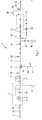
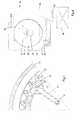
Fig. 1 is a schematic view of the main treatment line;Fig. 2 is a schematic view of the secondary treatment line;Fig. 3 is a partly cross-section of the main filter;Fig. 4 is a schematic cross section of a rotary drum filter; andFig. 5 is a schematic front view and cross section of the main filter.- It should be appreciated, however, that these embodiments may not be construed as limiting the scope of protection for the present invention.
- Vessels travelling over the seas usually have ballast tanks in order to trim the vessel in dependence of the load situation. Ballast water is pumped from the surrounding water into the ballast tanks when, e.g., a vessel is not loaded with cargo, or water is pumped from the ballast tanks to the surrounding water when, e.g., the vessel is heavily loaded with cargo. The intake and outlet of the ballast water may occur at different locations and in different harbours, which may lead to undesired spreading of organisms now living only at specific locations of the world. The described system cleans and sanitizes a water flow and the system might be used to clean ballast water pumped from ballast tanks of a vessel.
- In an embodiment the system may also be used to clean a water flow into a storage tank whereby the water stored in the storage tank might be used to rinse the ballast tank of for instance a semi-submersible ship so that this ship may use his ballast tanks during loading/unloading of cargo. Other embodiments where the system is used for other application for cleaning and sanitizing a water flow are also possible, these embodiments more or less use the same components as the embodiment described with the aid of the figures.
- As shown in
Fig. 1 , a main treatment line 1 of a system for cleaning and sterilizing a water flow comprises aninlet 2 to connect with an outlet of a ballast tank or ballast tanks of a vessel (not shown). A self-priming unit 3 with apump 56 is provided downstream to theinlet 2, such that it is possible to pump ballast water from the ballast tank(s) of the vessel into the main treatment line 1 even when the vessel is not able to pump ballast water from the ballast tank(s) to the system by itself. - The main treatment line 1 comprises conduits and appendages made of materials comprising ceramic, Fe, CuNi, plastic, etc. and/or a combination thereof, in order to prevent corrosion and undesired growth of organisms.
- The self-priming unit 3 removes, if required, air from a
line 57, which in this case is the line between the self-priming unit and the ballast tank(s) of the vessel, such that thepump 56 eventually pumps water from the ballast tank(s) into the system. In the case that the vessel uses a pump to pump water from the ballast tank(s) into the main treatment line 1, the self-priming unit functions as an additional pump or thepump 56 remains idle. - The pressure in a
suction line 5 is determined by means of one ormore pressure sensors 6 and when this pressure is above a specified limit, for example 1.1 bar (110 kPa), for a predetermined time period, for example 60 seconds, a bypass (not shown) might be opened and the water flow bypasses the self-priming unit. - A
straining unit 7 is provided downstream to the self-priming unit. Thestraining unit 7 filters solids from the water that have entered the main treatment line 1. Solids, such as screws, scrap or other objects, may cause damage to parts of the system and therefore have to be removed from the water. Thestraining unit 7 may have openings with a maximum dimension of 4 or 2 mm. It is noted that in other embodiments of the system the straining unit may be positioned upstream to the self-priming unit 3 or may be positioned upstream to the outlet of the ballast tank(s) of the vessel (not shown). - Upstream and downstream to the
straining unit 7, apressure sensor 6 may be provided. It is possible to determine a pressure difference over the strainingunit 7, which pressure difference for example may indicate that thestraining unit 7 is obstructed by an object (not shown) and that urgent action is required. - In the embodiment shown in
Fig. 1 , amain filter 8 is provided downstream to thestraining unit 7. Themain filter 8 comprises ahousing 15 with an inlet and an outlet (not shown). As can be seen inFig. 3 , themain filter 8 comprises anannular element 10 with a plurality ofopenings 11. Around the annular element 10 a corrugatedfirst filter element 12 is provided, such that after a row ofopenings 11 in the annular element 10 afilter chamber 13 is formed. Within theannular element 10, a backflush member with abackflush arm 14 is provided which seals against theannular element 10 and extends over at least a width equally to the distance between theopenings 11. At the end of thebackflush arm 14, which is near the annular element 10 a small tolerance between the end and theannular element 10 is provided to reduce the amount of water that enters thebackflush arm 14 from within theannular element 10. Alternatively, seals (not shown) are provided at the end of thebackflush arm 14, which end is in contact with theannular element 10. Thebackflush arm 14 is connected to apump 9 in order to aid the backflush over thefilter chambers 13. A driving unit (not shown) is connected to thebackflush arm 14 to rotatably drive thebackflush arm 14 within theannular element 10, as indicated with arrow A. The driving unit and thepump 9 are connected to a controller (not shown), which controls the driving unit and thepump 9 on basis of predetermined parameters, such as time and/or pressure build up within theannular element 10. The main water flow, in use, flows from the inside of theannular element 10 to the outside of theannular element 10. - It is noted that it is possible that the flow of backflush water over the
filter elements 12 chambers is provided on basis of the pressure in thehousing 15 at the downstream side of thefilter element 12 and that there is nopump 9 for aiding the flow of backflush water. - The
first filter element 12 has filter openings with a largest dimension of less than 10 micron or 6 micron. Filter material with such small openings can be made from meshed wires, for instance from stainless steel wires material 316L or similar or from 304, Monel or other metal wires. Synthetic materials is also possible. The wires are very thin, and for the single woven meshed wires the smallest aperture width of the filter mesh is similar to the wire thickness. More complicated wire mesh is possible, such as Twill Dutch Weave, which makes smaller apertures possible. In other embodiments the filter material might consist of metal plates from the same materials as earlier mentioned, in which holes with a diameter of 6 or 10 micrometer are made, for instance using pulsed laser beams. - In the disclosed embodiment there are no filter openings with larger dimensions than 6 or 10 micrometers. Due to the fairly high pressure difference over the
first filter element 12 and the structure of the organisms, filter elements with filter openings having a maximum opening of approximately 10 or 6 micron cause that the larger organisms are fragmented into smaller parts before passing the filter. - An organism that is larger than the filter opening will be fragmented and/or will be pulled into separate small pieces which can flow through the filter openings of the
first filter element 12.Figure 5 illustrates this process and shows an organism O on thefirst filter element 12, which is shown schematically in front view (fig 5a ) on a wire mesh weave and in a cross section (fig. 5b ) on a metal plate with laser pulsed holes. On the upstream side an organism O lies against thefilter element 12 and closessmall filter openings 12a. - The pressure difference over the
first filter element 12 presses on the organism O and fragments of the organism O will be pressed through thesmall filter openings 12a. The organism O shall disintegrate and shall flow in small pieces through theopenings 12a. Hard parts in an organism may remain on the pressure side of thefilter element 12 and will be removed by backflushing. Themain filter 8 is designed such that the pressure difference over thefirst filter element 12 is higher than 0.1 bar (10 kPa) or might be higher than 0.2 bar (20 kPa). This pressure difference is sufficient to fragment the organisms O. - During operation, the pressure in the
annular chamber 10 is approximately 2 bar (200 kPa) and a pressure difference of the main flow over thefirst filter element 12 is limited to 0.3 bar (30 kPa). Pressure sensors (not shown) are provided for measuring the pressure, which pressure sensors send a signal to the controller when the pressure difference over thefirst filter element 12 exceeds 0.3 bar (30 kPa). The controller then starts the flow of backflush water in order to clean thefirst filter elements 12. - It is also possible that a
flow sensor 16 is provided downstream to themain filter 8 for measuring the flow from themain filter 8. In an embodiment, theflow sensor 16 sends a signal to the controller in order to start the backflush, when theflow sensor 16 senses that the flow in the main treatment line 1 is below a predetermined limit. - The flow of backflush water has a pressure difference over the
first filter element 12 of approximately 1.6 bar (160 kPa). The backflush water rinses silt consisting of removed organisms and other removed particles out of thefilter chambers 13 one by one, which silt themain filter 8 has filtered out of the main flow. Anoutlet 17 of the backflush arm is connected to aninlet 18 of an secondary treatment line 19 (seeFig. 2 ) of the system for cleaning and sanitizing a water flow, which is described in relation to and is shown in detail inFig. 2 . - After the water in the main treatment line has passed the
main filter 8, the water enters a sterilizing station, in this embodiment a first UV-station 20 to radiate the water with UV-radiation. The UV-radiation kills and/or stops growth of any remaining organisms in the water. In this embodiment, the first UV-station 20 comprises two UV-lamps 21 to radiate the water. In practice, a UV-lamp needs about 5 minutes to start up in order that the radiation is strong enough to kill organisms. It is therefore contemplated that always one UV-lamp is switched on, such that it is possible to start treating ballast water immediately. In practice, the UV-lamp can be burning at half the maximum strength. It is noted that a C.I.P. (Cleaning In Place) system (not shown) may be provided to clean the UV-lamps 21 or their housings. - The fragmented parts of organisms that flow through the
first filter element 12 have been pressed through openings of 6 or 10 micrometre. Although they may have some length the UV radiation can penetrate easy into the fragmented organisms. The irradiation of these fragmented parts is very effective and the power requirement for killing the organisms is limited. - In this embodiment of the system, a cooling
line 22, optionally with an air cooled water cooler, is provided parallel to the first UV-station. The coolingline 22 is connected to the main treatment line 1 upstream and downstream to the first UV-station 20, such that a loop is created. In the case that the water flow through the first UV-station 20 is minimal, water can be contained within theloop 22 and the water can be circulated through the coolingline 22 and the first UV-station 20 by means of,e.g., apump 24, distributing the heat and thereby cooling the lighted UV-lamp. - Optionally, the water flow may be blocked before and after the first UV-
station 20, such that it is possible to circulate water through the coolingline 22. The UV-lamp(s) radiating the water may cause the temperature of the water to increase, which may cause the water to expand. An expansion tank with a membrane (not shown) may be provided near and connected to the first UV-station 20, such that expansion of the water caused by the UV-lamp(s) 21 may be absorbed by the expansion tank (not shown). - In other embodiments, the first UV-
station 20 might be replaced by other systems for sterilizing the water flow, such as systems for sterilization with ozone, chloride, or similar systems. The sterilizing system kills the remaining organisms or incapacitates the reproduction, so that no fertile or viable organisms remain. - In order to provide sufficient pressure within the main treatment line 1 and the
housing 15 of themain filter 8, a pressure regulating member, such as aflow controlling valve 10 is provided downstream to themain filter 8. Theflow control valve 10 may be provided with a pressure sensor sensing the pressure within the main treatment line 1. Theflow control valve 10 is connected to the controller (not shown), such that the pressure in the main treatment line 1 can be adjusted continuously. The pressure is used to monitor the filtering of the main flow through themain filter 8 and to control the flow of backflush water to ensure it is strong enough to rinse out thefilter chambers 13. In this embodiment the pressure regulating member is a flow control valve. The flow control valve may also stop the flow before the first UV-station. - Due to the
flow control valve 10, a system is provided with an adjustable water flow through the main treatment line 1. In an embodiment, the system may be controlled automatically. - A
flow control valve 54 can also be provided downstream to thebackflush member 14 in order to control the flow through thebackflush member 14. - In this embodiment, after the water has passed the first UV-
station 20, there is agooseneck 25. On top of the gooseneck anaeration valve 26 is provided de-aerate the main flow line so that during use the UV-station 20 remains filled with water to provide cooling of the UV lamps. One ormore sample elements 29 are provided upstream to thegooseneck 25, whichsample elements 29 are configured to sample the water. Thereafter, the water is discharged into the environmental water via anoutlet 30. Fig. 2 shows the secondary treatment line 19 of the system for cleaning and sanitizing a water flow. The secondary treatment line 19 comprises aninlet 18 connected to theoutlet 17 of thebackflush member 14. The water from thebackflush member 14 is collected in thebackflush filter 31, which is a rotary drum filter in this embodiment. An advantage of therotary drum filter 31 is that little pressure difference is needed in order to filter the water, since the water flow is a gravitational flow through a large filter area. Thebackflush filter 31 might be called a gravitational filter as no pump pressure is used to press the water flow through the filter material, the filter material might be chosen from the material as described for the main filter.- Any air and spray from the self-priming unit 3 or other vent valve(s) may enter the
rotary drum filter 31 throughinlet 27, such that organisms particles in the air and spray are removed in the secondary treatment line 19 of the system and no organisms leave the system. The housing of therotary drum filter 31 is provided withaeration openings 53 breathing air at low speed, so that no spray with organisms occur. - As shown in detail in
Fig. 4 , the firstrotary drum filter 31 comprises adrum 32 within acontainer 33 and inside thedrum 32 the water to be filtered. Adrive 28 is provided, which drive 28 is connected to the controller (not shown). The controller controls thedrive 28 to rotate thedrum 32 of therotating drum filter 31 continuously or intermittently. Water enters therotary drum filter 31 at the inside viainlet 34 of the drum, whichinlet 34 is in fluid communication toinlet 18, and thereafter flows through the drum elements with filter openings to the outside 35 of thedrum 32, thereby passing a drum element that is part of thedrum 32. The drum element has filter openings with a largest dimension of approximately 40 micron, 30 micron, 25 micron or 20 micron, which is sufficient to filter out, in a gravitational flow, organisms that are larger than 50 micron. Also in this case, this means that there are no filter openings with larger dimensions. - In the first
rotary drum filter 32 the pressure difference over the drum elements is limited to 0.05 bar (5 kPa) so that the larger organisms are not pressed through the filter mesh. This limited pressure difference is called gravitational flow. In order to ensure this limited pressure difference in an embodiment the water level on the outside 35 of thedrum 32 is above the underside of thedrum 32. This limits the pressure difference over the drum elements to 5 kPa, 3 kPa or even to 1 kPa. An elbow pipe (not shown) with an opening extending upwards and connected to theoutlet conduit 45 ensures this limitation in the pressure difference. - In an embodiment, inside the first
rotary drum filter 31, a sensor (not shown) measures the water level, which sensor is connected to the controller. In the case that the sensor senses that the water level reaches a certain level, which is an indication that the filter openings are clogged by silt, which is the residue of the organisms filtered out by the drum elements, a signal is sent to the controller. The controller then sends a signal to a rinsing system, in thisembodiment spray elements 36 to start spraying the outside surface of thedrum 32. Thespray elements 36 are located above a receivingstation 37. The silt is sprayed from the drum elements, which silt falls into the receivingstation 37. The receivingstation 37 is connected to asilt tank 38 for collecting the silt from therotary drum filter 31. It is noted that no light is able to enter therotary drum filter 31 in order to prevent algae growth on thedrum 32. - The drum of a rotary drum filter may comprise
projections 55 intended for preventing the silt from moving downwards over the drum elements during rotating of the drum. - After the first
rotary drum filter 31 has filtered the water, in the shown embodiment, the water enters ansecond backflush filter 39 viaoutlet conduit 45, in this case a secondrotary drum filter 39, which is similar to and functions substantially the same as the firstrotary drum filter 31. The drum of the secondrotary drum filter 39 may have openings with a diameter of 50 micron, 45 micron, or 40 micron, 30 micron, 25 micron, or 20 micron. Awater tank 40 is provided for collecting water leaving the additionalrotary drum filter 39. Thespray elements 36 of the firstrotary drum filter 31 and the secondrotary drum filter 39 are fed with water from thewater tank 40 viaconduit 49 and optionally pump 50. It is noted that no light is able to enter the water tank in order to prevent algae growth on the filter. - In this embodiment, a third
rotary drum filter 47 is provided downstream to the secondrotary drum filter 39. Viaoutlet conduit 51 the water filtered by therotary drum filter 31 and the secondrotary drum filter 39 enters the thirdrotary drum filter 47. In this case, the firstrotary drum filter 31 serves as a pre-filter. Further, therotary drum filter 31, the secondrotary drum filter 39 and the thirdrotary drum filter 47 may have different sizes or may be able to filter different amounts of water. In the shown embodiment, there are three backflush filters. In some situations only one or two backflush filter(s) might be sufficient. - In case there is more than one backflush filter, the surface of the filter material and the openings in the filter material are designed such that during use the different filters remove the same amount of silt; this means that the openings in the filter material of a backflush filter will get smaller in direction of the flow.
- The secondary line of the system for cleaning and sanitizing a water flow further comprises a
separator 23, such as a centrifuge connected to thesilt tank 38. Apump 41 pumps the silt from thesilt tank 38 into theseparator 40 and subsequently the separator separates water and sediment from the silt. The water from theseparator 40 is recirculated to theflush tank 28. The sediment, which is a sludge with a water content of about 7-15%, or which might have a water content of less than 20 % is routed to the outside of the system for cleaning and sanitizing a water flow viaoutlet 42 by mainly mechanical means, such as a displacement pump, after being stored in a storage area or a tank (not shown). - The water filtered by the backflush filters enters the main treatment line upstream to the first UV-
station 20 viainlet 44 such that water filtered in the secondary treatment line 19 is radiated during passing the first UV-station 20. Thereafter, the water is discharged into the environmental water. Apump 46, in this embodiment a centrifugal pump, is provided to pump the water from thewater tank 40 to the first UV-station. Downstream to thepump 46, aflow meter 43 may be provided which may be connected to the controller (not shown) - Optionally, in an embodiment (not shown), the secondary treatment line is provided with a second UV-station comprising at least one UV lamp. The UV-lamp is provided downstream to the
water tank 40, such that the filtered water of the secondary treatment line 19 can be irradiated with UV-radiation before the water is returned to the main treatment line 1 of the system for cleaning and sanitizing a water flow. Optionally, a valve may be provided downstream to the UV-lamp. Further, a recirculation line may be provided to recirculate water from a point downstream to the UV-lamp back to thewater tank 40. In this manner, it is possible to cool the UV-lamp. In an embodiment (not shown), downstream to thewater tank 40, the secondary treatment line may split into two lines. Each of the two lines may comprise a closing valve to close off the respective one of the two lines. In this way, it is controllable where the water from the secondary treatment line re-enters the main treatment line 1 viainlet 44 or an inlet downstream to the first UV-station 20. - A
process shutdown valve 48 may be provided to stop the process of the system for cleaning and sanitizing a water flow in case of an emergency or failure. In this embodiment a butterfly valve is placed at theinlet 2 of the system, which valve is closable by air. The process shutdown valve is connected to the controller, such that the process shutdown valve is controllable on basis of all parameters which are determined during use of the system. - Optionally, in an embodiment where the system for cleaning and sanitizing a water flow is placed within a container (not shown), a water pump may be provided at the bottom of the container. The water pump may be in fluid communication with the
backflush filter 31. In case a leakage occurs, the water can be pumped into theflush tank 28 such that no water with organisms leaks to the environment. - It is noted that all sealing and connections within the system for removing floating particles from a water flow are such that no particles or organisms can get stuck in for example a groove of the connection. The system further comprises different kinds of valves and connection points which are not discussed in detail, but are shown in the figures.
- The device for cleaning and sanitizing a water flow is capable to treat a total maximum of 1000 m3/h. for this capacity the first filter element may have a surface area of 8 m2 and the backflush filters may have a surface area of 3-6 m2.
- It is noted that the drawings are schematic, not necessarily to scale and that details that are not required for understanding the present invention may have been omitted. The terms "upward", "downward", "below", "above", and the like relate to the embodiments as oriented in the drawings, unless otherwise specified. Further, elements that are at least substantially identical or that perform an at least substantially identical function are denoted by the same numeral.
- The invention is not restricted to the above-described embodiments, which can be varied in a number of ways within the scope of the claims. It is, for example possible device for cleaning and sanitizing a water flow comprises two main lines and two secondary lines for removing the organisms from a water flow. The device is then capable to treat a total maximum of 2000 m3/h. Also two main treatment lines may be connected to one secondary line and/or two secondary treatment lines may be connected to one separator of centrifuge.
- It is further possible that a monitoring panel is placed in a switchboard room with an interface for remote control of the valves and filters. The interface is connected to the controller as described above.
- In a further embodiment, the system may be permanently mounted in a ship so that all ballast water of that ship is routed through the system when entering and/or leaving the ship.
Claims (18)
- A system for cleaning and sterilizing a water flow, comprising:a main treatment line, comprising an inlet with a pump to pump water from a water storage, such as a ballast water tank of a vessel, through a main filter to a sterilizing station with one or more UV lamps to sterilize the water flow, and a system outlet,wherein the main filter is provided with a first filter element and a backflush member with a first backflush outlet to rinse the first filter element with backflush water,and a secondary treatment line, comprising an inlet being in fluid communication to the first backflush outlet, a backflush filter with a backflush filter element that has filter openings with a largest dimension between 50 micrometer and 20 micrometer to remove floating organisms or silt from the backflush water, and a secondary outlet being in fluid communication with the main treatment line, to lead filtered backflush water from the secondary treatment line to the main treatment line, wherein the backflush filter is designed such that a backflush pressure difference over the backflush filter element is less than 0.05 bar (5 kPa), andwherein the main filter is designed such that the pressure difference over the first filter element is at least 0.1 bar (10 kPa) or 0.2 bar (20 kPa) and wherein the largest dimensions of openings in the first filter element preferably are smaller than half or one third of the largest dimension of the openings in the backflush filter element.
- The system according to claim 1, wherein the backflush filter has a filter rinsing system to rinse the silt from the backflush filter element with rinsing water and the filter rinsing system is connected to a separator or centrifuge to remove rinsing water from the silt.
- The system according to claim 1 or 2, wherein the first filter element comprises first filter openings with a largest dimension of 10 micron or 6 micron.
- The system according any of the preceding claims, wherein the backflush member is configured to rinse less than 20% or less than 10% of the first filter openings of the first filter element simultaneously.
- The system according to any one of the preceding claims, wherein the secondary treatment line might comprise two or more backflush filters in line, wherein one of the backflush filters might have openings with a largest dimension of 25 micron or 20 micron.
- The system according to claim 5, wherein the first backflush filter in line has filters openings with a largest dimension that is greater than or equal to the following backflush filter(s).
- The system according to any one of the preceding claims, wherein at least one of the backflush filter(s) comprises a rotary drum filter.
- The system according to any one of the preceding claims, wherein the secondary outlet is connected to the main treatment line upstream relative to the sterilizing station or wherein the secondary treatment line has a second sterilizing station.
- The system according to any one of the preceding claims, wherein at least one of the UV-lamps in the sterilizing station is switched on continuously, which might be at a lower than full power.
- The system according to any one of the preceding claims, wherein the backflush filter comprises a filter rinsing system to rinse the silt from the backflush filter element with rinsing water, wherein an outlet of the filter rinsing system is connected to a silt tank to collect the rinsing water with the silt rinsed from the backflush filter(s), wherein the silt tank is connected to a separator, in particular a centrifuge, to dewater the silt, and wherein a first separator outlet is connected to the main treatment line or the secondary treatment line and a second separator outlet is connected to a storage area or to a storage tank to store the dewatered silt.
- The system according to any one of the preceding claims, wherein the main treatment line comprises a self-priming unit and/or a straining unit upstream with respect to the main filter.
- The system according to any one of the preceding claims, wherein the main treatment line comprises a pressure regulating element, in particular a flow control valve, to regulate the pressure at the downstream side of the first filter element.
- The system according to any one of the preceding claims, wherein the system is placed in a container, which might be a moveable container, and/or wherein the system is placed on a vehicle, such as a truck, and/or on a vessel, such as a barge.
- The system according to any one of the preceding claims, wherein all vent valves upstream of the sterilizing station are connected to a tank that drains upstream of the sterilizing station.
- Method for cleaning and sterilizing a water flow, wherein the water flow is pumped through a first filter element of a main filter under a first pressure difference of at least 0.1 bar (10 kPa) or 0.2 bar (20 kPa) ;
wherein the first filter element can be rinsed with a flow of backflush water and the organisms in the backflush water are filtered out as silt in a backflush filter with a backflush filter element that has filter openings with a largest dimension between 50 micrometer and 20 micrometer;
wherein when a backflush pressure difference over the back flush filter element is more than 0.05 bar (5kPa), the backflush filter is cleaned with a water spray and the water spray with silt is dewatered in a separator and the dewatered silt is stored for later disposal;
wherein the water flowing from the main filter and the backflush filter is sterilized in a sterilizing station using UV radiation and guided to the environment, and the water flowing from the separator is re-entered into the system upstream of the main filter and/or the backflush filter. - The method according to claim 15, wherein the largest dimension of the openings in the first filter element is smaller than half of the largest dimension of the openings in the backflush filter element or are smaller than 10 or 6 micrometer.
- The method according to claim 15 or 16, the method comprising steps for:measuring the first pressure difference over the first filter element, andwhen the first pressure difference exceeds 0.3 bar (30 kPa), starting the flow of backflush water to rinse the first filter element.
- The method according to any one of claims 15-17, wherein the backflush filter is a rotary drum filter, the method further comprising steps for:measuring a water level within a drum of the rotary drum filter, andwhen the water level reaches a predetermined level in the drum, activating the filter rinsing system to remove silt from the inside surface of the drum.
Priority Applications (18)
| Application Number | Priority Date | Filing Date | Title |
|---|---|---|---|
| EP14196254.8AEP2947053B1 (en) | 2014-05-21 | 2014-12-04 | System and method for cleaning and sterilizing a ballast water flow |
| RU2016147002ARU2016147002A (en) | 2014-05-21 | 2015-05-21 | SYSTEM AND METHOD FOR CLEANING AND STERILIZING WATER FLOW |
| TN2016000485ATN2016000485A1 (en) | 2014-05-21 | 2015-05-21 | System and method for cleaning and sterilizing a water flow. |
| EA201692115AEA031608B1 (en) | 2014-05-21 | 2015-05-21 | System and method for cleaning and sterilizing a water flow |
| KR1020167035307AKR20170016867A (en) | 2014-05-21 | 2015-05-21 | System and method for cleaning and sterilizing a water flow |
| BR112016026875-0ABR112016026875B1 (en) | 2014-05-21 | 2015-05-21 | SYSTEM FOR CLEANING AND STERILIZING A WATER FLOW |
| JP2016568850AJP2017516647A (en) | 2014-05-21 | 2015-05-21 | System and method for cleaning and sterilizing water streams |
| EP15732169.6AEP3145874B1 (en) | 2014-05-21 | 2015-05-21 | System for cleaning and sterilizing a water flow |
| AU2015261833AAU2015261833B2 (en) | 2014-05-21 | 2015-05-21 | System and method for cleaning and sterilizing a water flow |
| CN201580026263.2ACN106458674A (en) | 2014-05-21 | 2015-05-21 | System and method for cleaning and sterilizing a water flow |
| PCT/EP2015/061260WO2015177280A1 (en) | 2014-05-21 | 2015-05-21 | System and method for cleaning and sterilizing a water flow |
| SG11201609444QASG11201609444QA (en) | 2014-05-21 | 2015-05-21 | System and method for cleaning and sterilizing a water flow |
| MX2016015201AMX2016015201A (en) | 2014-05-21 | 2015-05-21 | System and method for cleaning and sterilizing a water flow. |
| CA2948433ACA2948433C (en) | 2014-05-21 | 2015-05-21 | System and method for cleaning and sterilizing a water flow |
| US15/312,576US10464821B2 (en) | 2014-05-21 | 2015-05-21 | System and method for cleaning and sterilizing a water flow |
| SA516380325ASA516380325B1 (en) | 2014-05-21 | 2016-11-17 | System for Cleaning and Sterilizing a Water Flow |
| CL2016002978ACL2016002978A1 (en) | 2014-05-21 | 2016-11-21 | Water cleaning and sterilization system of a ship's ballast tank, method |
| PH12016502314APH12016502314A1 (en) | 2014-05-21 | 2016-11-21 | System and method for cleaning and sterilizing a water flow |
Applications Claiming Priority (2)
| Application Number | Priority Date | Filing Date | Title |
|---|---|---|---|
| EP14169245 | 2014-05-21 | ||
| EP14196254.8AEP2947053B1 (en) | 2014-05-21 | 2014-12-04 | System and method for cleaning and sterilizing a ballast water flow |
Publications (2)
| Publication Number | Publication Date |
|---|---|
| EP2947053A1true EP2947053A1 (en) | 2015-11-25 |
| EP2947053B1 EP2947053B1 (en) | 2018-11-07 |
Family
ID=50735965
Family Applications (2)
| Application Number | Title | Priority Date | Filing Date |
|---|---|---|---|
| EP14196254.8ANot-in-forceEP2947053B1 (en) | 2014-05-21 | 2014-12-04 | System and method for cleaning and sterilizing a ballast water flow |
| EP15732169.6AActiveEP3145874B1 (en) | 2014-05-21 | 2015-05-21 | System for cleaning and sterilizing a water flow |
Family Applications After (1)
| Application Number | Title | Priority Date | Filing Date |
|---|---|---|---|
| EP15732169.6AActiveEP3145874B1 (en) | 2014-05-21 | 2015-05-21 | System for cleaning and sterilizing a water flow |
Country Status (17)
| Country | Link |
|---|---|
| US (1) | US10464821B2 (en) |
| EP (2) | EP2947053B1 (en) |
| JP (1) | JP2017516647A (en) |
| KR (1) | KR20170016867A (en) |
| CN (1) | CN106458674A (en) |
| AU (1) | AU2015261833B2 (en) |
| BR (1) | BR112016026875B1 (en) |
| CA (1) | CA2948433C (en) |
| CL (1) | CL2016002978A1 (en) |
| EA (1) | EA031608B1 (en) |
| MX (1) | MX2016015201A (en) |
| PH (1) | PH12016502314A1 (en) |
| RU (1) | RU2016147002A (en) |
| SA (1) | SA516380325B1 (en) |
| SG (1) | SG11201609444QA (en) |
| TN (1) | TN2016000485A1 (en) |
| WO (1) | WO2015177280A1 (en) |
Cited By (3)
| Publication number | Priority date | Publication date | Assignee | Title |
|---|---|---|---|---|
| CN106669261A (en)* | 2017-01-05 | 2017-05-17 | 昆明滇池湖泊治理开发有限公司 | Device for directly high-efficiently treating blue-green algae in water |
| CN110615567A (en)* | 2019-10-12 | 2019-12-27 | 李德峰 | Be used for abluent sewage treatment system of car |
| CN114405128A (en)* | 2022-01-24 | 2022-04-29 | 中国水产科学研究院渔业机械仪器研究所 | A backwash device for a microfilter |
Families Citing this family (25)
| Publication number | Priority date | Publication date | Assignee | Title |
|---|---|---|---|---|
| US9885196B2 (en) | 2015-01-26 | 2018-02-06 | Hayward Industries, Inc. | Pool cleaner power coupling |
| JP6780306B2 (en)* | 2016-06-06 | 2020-11-04 | 三浦工業株式会社 | Cooling method for ballast water treatment equipment and UV treatment means for ballast water treatment equipment |
| US10214933B2 (en) | 2017-05-11 | 2019-02-26 | Hayward Industries, Inc. | Pool cleaner power supply |
| US10189490B2 (en) | 2017-05-11 | 2019-01-29 | Hayward Industries, Inc. | Pool cleaner caddy with removable wheel assemblies |
| US10364905B2 (en) | 2017-05-11 | 2019-07-30 | Hayward Industries, Inc. | Pool cleaner check valve |
| US9885194B1 (en) | 2017-05-11 | 2018-02-06 | Hayward Industries, Inc. | Pool cleaner impeller subassembly |
| US9896858B1 (en) | 2017-05-11 | 2018-02-20 | Hayward Industries, Inc. | Hydrocyclonic pool cleaner |
| US10156083B2 (en) | 2017-05-11 | 2018-12-18 | Hayward Industries, Inc. | Pool cleaner power coupling |
| US10676950B2 (en) | 2017-05-11 | 2020-06-09 | Hayward Industries, Inc. | Pool cleaner roller latch |
| US10227081B2 (en) | 2017-05-11 | 2019-03-12 | Hayward Industries, Inc. | Pool cleaner caddy with retention mechanism |
| US10161153B2 (en) | 2017-05-11 | 2018-12-25 | Hayward Industries, Inc. | Pool cleaner canister handle |
| US9878739B1 (en) | 2017-05-11 | 2018-01-30 | Hayward Industries, Inc. | Pool cleaner modular drivetrain |
| US11767095B2 (en) | 2017-05-29 | 2023-09-26 | Bawat A/S | System and a method for heat treatment of water of a vessel |
| US20210371314A1 (en)* | 2018-04-23 | 2021-12-02 | Sinku Water Services Corp. | Systems and methods for hull wastewater remediation |
| US11117816B2 (en)* | 2018-08-13 | 2021-09-14 | Geberit International Ag | Water disinfecting module, systems and methods |
| EP3666640A1 (en)* | 2018-12-14 | 2020-06-17 | ABB Schweiz AG | Water treatment device |
| CA3057084A1 (en)* | 2019-01-09 | 2020-07-09 | Jeremy Leonard | Centrifugal separator |
| US11529573B2 (en)* | 2019-04-23 | 2022-12-20 | Greatpyr Resources Llc | Systems and processes employing wet/dry suction filter |
| CN110180257A (en)* | 2019-05-15 | 2019-08-30 | 安徽金宇阳电子科技有限公司 | A kind of abrasive waste water processing method |
| CN112209542A (en)* | 2019-07-10 | 2021-01-12 | 九江精密测试技术研究所 | Portable ballast water processing system in harbour |
| CN110453747A (en)* | 2019-09-10 | 2019-11-15 | 毅康科技有限公司 | A recyclable metal mechanism for river cleaning |
| US12377372B2 (en) | 2021-06-08 | 2025-08-05 | Greatpyr Resources Llc | Apparatus, systems, and processes employing wet/dry suction filter with chicaned suction head |
| CN113279711B (en)* | 2021-06-08 | 2022-09-20 | 山东省地矿工程勘察院 | Drilling fluid circulation system |
| JP2024136519A (en)* | 2023-03-24 | 2024-10-04 | ヤンマーホールディングス株式会社 | Water purification device and purification system |
| CN120328811B (en)* | 2025-06-20 | 2025-09-02 | 济南泰德天成环境科技有限公司 | Ozone biological activated carbon combined ultrafiltration integrated water purifying device |
Citations (5)
| Publication number | Priority date | Publication date | Assignee | Title |
|---|---|---|---|---|
| CN102316952A (en)* | 2009-02-16 | 2012-01-11 | 株式会社可乐丽 | Filtering unit and ballast water production equipment provided with same |
| WO2013027125A2 (en)* | 2011-08-23 | 2013-02-28 | Pr Aqua Supplies Ltd. | Apparatus and methods for sequential treatments of process flows |
| WO2013072476A1 (en)* | 2011-11-16 | 2013-05-23 | Pureteq A/S | A liquid treatment device |
| WO2013178296A1 (en) | 2012-06-01 | 2013-12-05 | Desmi Ocean Guard A/S | De-ballast filtration |
| WO2014035343A1 (en) | 2012-08-30 | 2014-03-06 | Sembawang Shipyard Pte Ltd | System and method of ballast water treatment with continuous biofouling control |
Family Cites Families (15)
| Publication number | Priority date | Publication date | Assignee | Title |
|---|---|---|---|---|
| CA1060351A (en) | 1973-12-26 | 1979-08-14 | Lloyd Ewing | Microscreening method and apparatus |
| US6125481A (en)* | 1999-03-11 | 2000-10-03 | Sicilano; Edward N. | Swimming pool management system |
| AU2003294487A1 (en) | 2003-11-20 | 2005-07-14 | Marine Environmental Partners, Inc. | Ballast water treatment system |
| WO2006008729A1 (en) | 2004-07-21 | 2006-01-26 | Amiad Filtration Systems (1997) Ltd. | Filter cleaning head |
| DE102006045558A1 (en)* | 2006-09-25 | 2008-04-03 | Rwo Gmbh | Water treatment plant |
| WO2010019526A1 (en)* | 2008-08-14 | 2010-02-18 | Brent Lee | Dynamic filtration device using centrifugal force |
| RU113264U1 (en) | 2011-04-29 | 2012-02-10 | Российская Федерация, От Имени Которой Выступает Министерство Промышленности И Торговли Российской Федерации | SHIPBALL DEVICE FOR DISCONNECTING BALLAST WATER |
| US8926843B2 (en)* | 2011-06-21 | 2015-01-06 | Veolia Water Solutions & Technologies Support | Method and apparatus for treating water and controlling effluent surges produced by disc and drum filters |
| WO2013070085A1 (en) | 2011-11-07 | 2013-05-16 | Timbernor Ou | A system for cleaning ballast water |
| US9255025B2 (en)* | 2012-07-20 | 2016-02-09 | ProAct Services Corporation | Method for the treatment of wastewater |
| DE102012015346A1 (en)* | 2012-08-06 | 2014-02-20 | Wirtgen Gmbh | Self-propelled construction machine |
| DE102012018996A1 (en) | 2012-09-27 | 2014-03-27 | Klaus Büttner | Process for treating ballast water and apparatus for treating ballast water |
| KR101427478B1 (en)* | 2012-10-18 | 2014-08-08 | 현대중공업 주식회사 | Sea Water Flow Control System for Treatment Apparatus of Ship's Ballast Water |
| CN203269706U (en)* | 2013-03-22 | 2013-11-06 | 江苏科技大学 | Ship ballast water treatment device based on filtration and ultraviolet sterilization |
| US20150174509A1 (en)* | 2013-12-20 | 2015-06-25 | Hollingsworth & Vose Company | Filter media with fine staple fibers |
- 2014
- 2014-12-04EPEP14196254.8Apatent/EP2947053B1/ennot_activeNot-in-force
- 2015
- 2015-05-21RURU2016147002Apatent/RU2016147002A/ennot_activeApplication Discontinuation
- 2015-05-21USUS15/312,576patent/US10464821B2/enactiveActive
- 2015-05-21EPEP15732169.6Apatent/EP3145874B1/enactiveActive
- 2015-05-21CACA2948433Apatent/CA2948433C/enactiveActive
- 2015-05-21EAEA201692115Apatent/EA031608B1/ennot_activeIP Right Cessation
- 2015-05-21KRKR1020167035307Apatent/KR20170016867A/ennot_activeWithdrawn
- 2015-05-21WOPCT/EP2015/061260patent/WO2015177280A1/enactiveApplication Filing
- 2015-05-21JPJP2016568850Apatent/JP2017516647A/enactivePending
- 2015-05-21TNTN2016000485Apatent/TN2016000485A1/enunknown
- 2015-05-21MXMX2016015201Apatent/MX2016015201A/enunknown
- 2015-05-21AUAU2015261833Apatent/AU2015261833B2/ennot_activeCeased
- 2015-05-21SGSG11201609444QApatent/SG11201609444QA/enunknown
- 2015-05-21BRBR112016026875-0Apatent/BR112016026875B1/ennot_activeIP Right Cessation
- 2015-05-21CNCN201580026263.2Apatent/CN106458674A/enactivePending
- 2016
- 2016-11-17SASA516380325Apatent/SA516380325B1/enunknown
- 2016-11-21CLCL2016002978Apatent/CL2016002978A1/enunknown
- 2016-11-21PHPH12016502314Apatent/PH12016502314A1/enunknown
Patent Citations (5)
| Publication number | Priority date | Publication date | Assignee | Title |
|---|---|---|---|---|
| CN102316952A (en)* | 2009-02-16 | 2012-01-11 | 株式会社可乐丽 | Filtering unit and ballast water production equipment provided with same |
| WO2013027125A2 (en)* | 2011-08-23 | 2013-02-28 | Pr Aqua Supplies Ltd. | Apparatus and methods for sequential treatments of process flows |
| WO2013072476A1 (en)* | 2011-11-16 | 2013-05-23 | Pureteq A/S | A liquid treatment device |
| WO2013178296A1 (en) | 2012-06-01 | 2013-12-05 | Desmi Ocean Guard A/S | De-ballast filtration |
| WO2014035343A1 (en) | 2012-08-30 | 2014-03-06 | Sembawang Shipyard Pte Ltd | System and method of ballast water treatment with continuous biofouling control |
Cited By (4)
| Publication number | Priority date | Publication date | Assignee | Title |
|---|---|---|---|---|
| CN106669261A (en)* | 2017-01-05 | 2017-05-17 | 昆明滇池湖泊治理开发有限公司 | Device for directly high-efficiently treating blue-green algae in water |
| CN106669261B (en)* | 2017-01-05 | 2022-10-11 | 李艳华 | Equipment for directly treating blue algae in water body at high efficiency |
| CN110615567A (en)* | 2019-10-12 | 2019-12-27 | 李德峰 | Be used for abluent sewage treatment system of car |
| CN114405128A (en)* | 2022-01-24 | 2022-04-29 | 中国水产科学研究院渔业机械仪器研究所 | A backwash device for a microfilter |
Also Published As
| Publication number | Publication date |
|---|---|
| CN106458674A (en) | 2017-02-22 |
| KR20170016867A (en) | 2017-02-14 |
| RU2016147002A (en) | 2018-06-22 |
| SG11201609444QA (en) | 2016-12-29 |
| EP3145874B1 (en) | 2019-10-16 |
| US20170088435A1 (en) | 2017-03-30 |
| AU2015261833B2 (en) | 2019-08-15 |
| CA2948433C (en) | 2022-09-20 |
| RU2016147002A3 (en) | 2018-12-13 |
| CA2948433A1 (en) | 2015-11-26 |
| MX2016015201A (en) | 2017-05-30 |
| WO2015177280A1 (en) | 2015-11-26 |
| US10464821B2 (en) | 2019-11-05 |
| BR112016026875A2 (en) | 2017-08-15 |
| EA201692115A1 (en) | 2017-05-31 |
| CL2016002978A1 (en) | 2017-04-07 |
| JP2017516647A (en) | 2017-06-22 |
| EP3145874A1 (en) | 2017-03-29 |
| EA031608B1 (en) | 2019-01-31 |
| AU2015261833A1 (en) | 2016-12-01 |
| BR112016026875B1 (en) | 2021-12-14 |
| SA516380325B1 (en) | 2020-04-07 |
| EP2947053B1 (en) | 2018-11-07 |
| TN2016000485A1 (en) | 2018-04-04 |
| PH12016502314A1 (en) | 2017-02-06 |
Similar Documents
| Publication | Publication Date | Title |
|---|---|---|
| EP3145874B1 (en) | System for cleaning and sterilizing a water flow | |
| JP5358440B2 (en) | Water purification equipment | |
| US8852441B2 (en) | Apparatus for purifying liquids, in particular for purifying ballast water | |
| US20150108071A1 (en) | De-ballast filtration | |
| TWI387480B (en) | Filtration unit and ballast water production apparatus using the same | |
| JP2010504855A (en) | Water treatment system | |
| AU1885302A (en) | Apparatus for sewage treatment | |
| KR20170041258A (en) | Ballast water treatment system and ballast water treatment method | |
| WO2010093025A1 (en) | Filtfering unit and ballast water production equipment provided with same | |
| KR20170028993A (en) | Ballast water treatment device, and method for treating ballast water | |
| EP2440450B1 (en) | Cleaning unit for cleaning of a ballast water treatment system, ballast water treatment system and use of such a system. | |
| WO2012164070A1 (en) | De-ballast filtration | |
| JP6296070B2 (en) | Ballast water treatment system and control method thereof | |
| JP2017100084A (en) | Filtration germicidal treatment system | |
| HK1231840A1 (en) | System and method for cleaning and sterilizing a water flow | |
| EP2855361B1 (en) | De-ballast filtration | |
| JP4754884B2 (en) | Backwash system | |
| JP5517113B1 (en) | Ballast water treatment equipment | |
| JP2017100076A (en) | Ballast water treatment equipment | |
| CN206345709U (en) | Ship | |
| KR20140118072A (en) | Ballast water process system for a ship using turbulent flow generator | |
| JP2013043144A (en) | Ballast water treatment apparatus | |
| JP2012205975A (en) | Water treatment apparatus | |
| HK1130760A (en) | Ballast water treatment plant having filter, disinfection, instrumentation and control unit |
Legal Events
| Date | Code | Title | Description |
|---|---|---|---|
| PUAI | Public reference made under article 153(3) epc to a published international application that has entered the european phase | Free format text:ORIGINAL CODE: 0009012 | |
| AK | Designated contracting states | Kind code of ref document:A1 Designated state(s):AL AT BE BG CH CY CZ DE DK EE ES FI FR GB GR HR HU IE IS IT LI LT LU LV MC MK MT NL NO PL PT RO RS SE SI SK SM TR | |
| AX | Request for extension of the european patent | Extension state:BA ME | |
| RAP3 | Party data changed (applicant data changed or rights of an application transferred) | Owner name:BV SCHEEPSWERF DAMEN GORINCHEM | |
| 17P | Request for examination filed | Effective date:20160523 | |
| RBV | Designated contracting states (corrected) | Designated state(s):AL AT BE BG CH CY CZ DE DK EE ES FI FR GB GR HR HU IE IS IT LI LT LU LV MC MK MT NL NO PL PT RO RS SE SI SK SM TR | |
| 17Q | First examination report despatched | Effective date:20170509 | |
| GRAP | Despatch of communication of intention to grant a patent | Free format text:ORIGINAL CODE: EPIDOSNIGR1 | |
| RIC1 | Information provided on ipc code assigned before grant | Ipc:C02F 1/38 20060101ALI20180309BHEP Ipc:B01D 33/50 20060101ALI20180309BHEP Ipc:C02F 1/00 20060101ALI20180309BHEP Ipc:B63J 4/00 20060101ALI20180309BHEP Ipc:B01D 33/46 20060101ALI20180309BHEP Ipc:C02F 103/00 20060101ALN20180309BHEP Ipc:B01D 33/11 20060101ALI20180309BHEP Ipc:C02F 1/32 20060101AFI20180309BHEP | |
| INTG | Intention to grant announced | Effective date:20180329 | |
| GRAJ | Information related to disapproval of communication of intention to grant by the applicant or resumption of examination proceedings by the epo deleted | Free format text:ORIGINAL CODE: EPIDOSDIGR1 | |
| GRAS | Grant fee paid | Free format text:ORIGINAL CODE: EPIDOSNIGR3 | |
| GRAP | Despatch of communication of intention to grant a patent | Free format text:ORIGINAL CODE: EPIDOSNIGR1 | |
| INTG | Intention to grant announced | Effective date:20180727 | |
| RIC1 | Information provided on ipc code assigned before grant | Ipc:C02F 1/00 20060101ALI20180717BHEP Ipc:B01D 33/11 20060101ALI20180717BHEP Ipc:C02F 103/00 20060101ALN20180717BHEP Ipc:C02F 1/32 20060101AFI20180717BHEP Ipc:B01D 33/46 20060101ALI20180717BHEP Ipc:B63J 4/00 20060101ALI20180717BHEP Ipc:C02F 1/38 20060101ALI20180717BHEP Ipc:B01D 33/50 20060101ALI20180717BHEP | |
| GRAA | (expected) grant | Free format text:ORIGINAL CODE: 0009210 | |
| AK | Designated contracting states | Kind code of ref document:B1 Designated state(s):AL AT BE BG CH CY CZ DE DK EE ES FI FR GB GR HR HU IE IS IT LI LT LU LV MC MK MT NL NO PL PT RO RS SE SI SK SM TR | |
| REG | Reference to a national code | Ref country code:GB Ref legal event code:FG4D | |
| REG | Reference to a national code | Ref country code:CH Ref legal event code:EP Ref country code:AT Ref legal event code:REF Ref document number:1061843 Country of ref document:AT Kind code of ref document:T Effective date:20181115 | |
| REG | Reference to a national code | Ref country code:DE Ref legal event code:R096 Ref document number:602014035499 Country of ref document:DE | |
| REG | Reference to a national code | Ref country code:IE Ref legal event code:FG4D | |
| REG | Reference to a national code | Ref country code:NL Ref legal event code:FP | |
| REG | Reference to a national code | Ref country code:LT Ref legal event code:MG4D | |
| REG | Reference to a national code | Ref country code:AT Ref legal event code:MK05 Ref document number:1061843 Country of ref document:AT Kind code of ref document:T Effective date:20181107 | |
| PG25 | Lapsed in a contracting state [announced via postgrant information from national office to epo] | Ref country code:LV Free format text:LAPSE BECAUSE OF FAILURE TO SUBMIT A TRANSLATION OF THE DESCRIPTION OR TO PAY THE FEE WITHIN THE PRESCRIBED TIME-LIMIT Effective date:20181107 Ref country code:AT Free format text:LAPSE BECAUSE OF FAILURE TO SUBMIT A TRANSLATION OF THE DESCRIPTION OR TO PAY THE FEE WITHIN THE PRESCRIBED TIME-LIMIT Effective date:20181107 Ref country code:NO Free format text:LAPSE BECAUSE OF FAILURE TO SUBMIT A TRANSLATION OF THE DESCRIPTION OR TO PAY THE FEE WITHIN THE PRESCRIBED TIME-LIMIT Effective date:20190207 Ref country code:LT Free format text:LAPSE BECAUSE OF FAILURE TO SUBMIT A TRANSLATION OF THE DESCRIPTION OR TO PAY THE FEE WITHIN THE PRESCRIBED TIME-LIMIT Effective date:20181107 Ref country code:HR Free format text:LAPSE BECAUSE OF FAILURE TO SUBMIT A TRANSLATION OF THE DESCRIPTION OR TO PAY THE FEE WITHIN THE PRESCRIBED TIME-LIMIT Effective date:20181107 Ref country code:ES Free format text:LAPSE BECAUSE OF FAILURE TO SUBMIT A TRANSLATION OF THE DESCRIPTION OR TO PAY THE FEE WITHIN THE PRESCRIBED TIME-LIMIT Effective date:20181107 Ref country code:BG Free format text:LAPSE BECAUSE OF FAILURE TO SUBMIT A TRANSLATION OF THE DESCRIPTION OR TO PAY THE FEE WITHIN THE PRESCRIBED TIME-LIMIT Effective date:20190207 Ref country code:IS Free format text:LAPSE BECAUSE OF FAILURE TO SUBMIT A TRANSLATION OF THE DESCRIPTION OR TO PAY THE FEE WITHIN THE PRESCRIBED TIME-LIMIT Effective date:20190307 Ref country code:FI Free format text:LAPSE BECAUSE OF FAILURE TO SUBMIT A TRANSLATION OF THE DESCRIPTION OR TO PAY THE FEE WITHIN THE PRESCRIBED TIME-LIMIT Effective date:20181107 | |
| PG25 | Lapsed in a contracting state [announced via postgrant information from national office to epo] | Ref country code:GR Free format text:LAPSE BECAUSE OF FAILURE TO SUBMIT A TRANSLATION OF THE DESCRIPTION OR TO PAY THE FEE WITHIN THE PRESCRIBED TIME-LIMIT Effective date:20190208 Ref country code:SE Free format text:LAPSE BECAUSE OF FAILURE TO SUBMIT A TRANSLATION OF THE DESCRIPTION OR TO PAY THE FEE WITHIN THE PRESCRIBED TIME-LIMIT Effective date:20181107 Ref country code:RS Free format text:LAPSE BECAUSE OF FAILURE TO SUBMIT A TRANSLATION OF THE DESCRIPTION OR TO PAY THE FEE WITHIN THE PRESCRIBED TIME-LIMIT Effective date:20181107 Ref country code:PT Free format text:LAPSE BECAUSE OF FAILURE TO SUBMIT A TRANSLATION OF THE DESCRIPTION OR TO PAY THE FEE WITHIN THE PRESCRIBED TIME-LIMIT Effective date:20190307 Ref country code:AL Free format text:LAPSE BECAUSE OF FAILURE TO SUBMIT A TRANSLATION OF THE DESCRIPTION OR TO PAY THE FEE WITHIN THE PRESCRIBED TIME-LIMIT Effective date:20181107 | |
| PG25 | Lapsed in a contracting state [announced via postgrant information from national office to epo] | Ref country code:DK Free format text:LAPSE BECAUSE OF FAILURE TO SUBMIT A TRANSLATION OF THE DESCRIPTION OR TO PAY THE FEE WITHIN THE PRESCRIBED TIME-LIMIT Effective date:20181107 Ref country code:IT Free format text:LAPSE BECAUSE OF FAILURE TO SUBMIT A TRANSLATION OF THE DESCRIPTION OR TO PAY THE FEE WITHIN THE PRESCRIBED TIME-LIMIT Effective date:20181107 Ref country code:CZ Free format text:LAPSE BECAUSE OF FAILURE TO SUBMIT A TRANSLATION OF THE DESCRIPTION OR TO PAY THE FEE WITHIN THE PRESCRIBED TIME-LIMIT Effective date:20181107 Ref country code:PL Free format text:LAPSE BECAUSE OF FAILURE TO SUBMIT A TRANSLATION OF THE DESCRIPTION OR TO PAY THE FEE WITHIN THE PRESCRIBED TIME-LIMIT Effective date:20181107 | |
| REG | Reference to a national code | Ref country code:CH Ref legal event code:PL | |
| REG | Reference to a national code | Ref country code:DE Ref legal event code:R097 Ref document number:602014035499 Country of ref document:DE | |
| PG25 | Lapsed in a contracting state [announced via postgrant information from national office to epo] | Ref country code:RO Free format text:LAPSE BECAUSE OF FAILURE TO SUBMIT A TRANSLATION OF THE DESCRIPTION OR TO PAY THE FEE WITHIN THE PRESCRIBED TIME-LIMIT Effective date:20181107 Ref country code:SK Free format text:LAPSE BECAUSE OF FAILURE TO SUBMIT A TRANSLATION OF THE DESCRIPTION OR TO PAY THE FEE WITHIN THE PRESCRIBED TIME-LIMIT Effective date:20181107 Ref country code:MC Free format text:LAPSE BECAUSE OF FAILURE TO SUBMIT A TRANSLATION OF THE DESCRIPTION OR TO PAY THE FEE WITHIN THE PRESCRIBED TIME-LIMIT Effective date:20181107 Ref country code:LU Free format text:LAPSE BECAUSE OF NON-PAYMENT OF DUE FEES Effective date:20181204 Ref country code:EE Free format text:LAPSE BECAUSE OF FAILURE TO SUBMIT A TRANSLATION OF THE DESCRIPTION OR TO PAY THE FEE WITHIN THE PRESCRIBED TIME-LIMIT Effective date:20181107 Ref country code:SM Free format text:LAPSE BECAUSE OF FAILURE TO SUBMIT A TRANSLATION OF THE DESCRIPTION OR TO PAY THE FEE WITHIN THE PRESCRIBED TIME-LIMIT Effective date:20181107 | |
| PLBE | No opposition filed within time limit | Free format text:ORIGINAL CODE: 0009261 | |
| STAA | Information on the status of an ep patent application or granted ep patent | Free format text:STATUS: NO OPPOSITION FILED WITHIN TIME LIMIT | |
| REG | Reference to a national code | Ref country code:IE Ref legal event code:MM4A | |
| REG | Reference to a national code | Ref country code:BE Ref legal event code:MM Effective date:20181231 | |
| 26N | No opposition filed | Effective date:20190808 | |
| GBPC | Gb: european patent ceased through non-payment of renewal fee | Effective date:20190207 | |
| PG25 | Lapsed in a contracting state [announced via postgrant information from national office to epo] | Ref country code:SI Free format text:LAPSE BECAUSE OF FAILURE TO SUBMIT A TRANSLATION OF THE DESCRIPTION OR TO PAY THE FEE WITHIN THE PRESCRIBED TIME-LIMIT Effective date:20181107 Ref country code:FR Free format text:LAPSE BECAUSE OF NON-PAYMENT OF DUE FEES Effective date:20190107 Ref country code:IE Free format text:LAPSE BECAUSE OF NON-PAYMENT OF DUE FEES Effective date:20181204 | |
| PG25 | Lapsed in a contracting state [announced via postgrant information from national office to epo] | Ref country code:BE Free format text:LAPSE BECAUSE OF NON-PAYMENT OF DUE FEES Effective date:20181231 | |
| PG25 | Lapsed in a contracting state [announced via postgrant information from national office to epo] | Ref country code:LI Free format text:LAPSE BECAUSE OF NON-PAYMENT OF DUE FEES Effective date:20181231 Ref country code:CH Free format text:LAPSE BECAUSE OF NON-PAYMENT OF DUE FEES Effective date:20181231 | |
| PG25 | Lapsed in a contracting state [announced via postgrant information from national office to epo] | Ref country code:GB Free format text:LAPSE BECAUSE OF NON-PAYMENT OF DUE FEES Effective date:20190207 Ref country code:MT Free format text:LAPSE BECAUSE OF NON-PAYMENT OF DUE FEES Effective date:20181204 | |
| PG25 | Lapsed in a contracting state [announced via postgrant information from national office to epo] | Ref country code:TR Free format text:LAPSE BECAUSE OF FAILURE TO SUBMIT A TRANSLATION OF THE DESCRIPTION OR TO PAY THE FEE WITHIN THE PRESCRIBED TIME-LIMIT Effective date:20181107 | |
| PG25 | Lapsed in a contracting state [announced via postgrant information from national office to epo] | Ref country code:HU Free format text:LAPSE BECAUSE OF FAILURE TO SUBMIT A TRANSLATION OF THE DESCRIPTION OR TO PAY THE FEE WITHIN THE PRESCRIBED TIME-LIMIT; INVALID AB INITIO Effective date:20141204 Ref country code:CY Free format text:LAPSE BECAUSE OF FAILURE TO SUBMIT A TRANSLATION OF THE DESCRIPTION OR TO PAY THE FEE WITHIN THE PRESCRIBED TIME-LIMIT Effective date:20181107 Ref country code:MK Free format text:LAPSE BECAUSE OF NON-PAYMENT OF DUE FEES Effective date:20181107 | |
| PGFP | Annual fee paid to national office [announced via postgrant information from national office to epo] | Ref country code:NL Payment date:20221228 Year of fee payment:9 | |
| PGFP | Annual fee paid to national office [announced via postgrant information from national office to epo] | Ref country code:DE Payment date:20221228 Year of fee payment:9 | |
| REG | Reference to a national code | Ref country code:DE Ref legal event code:R119 Ref document number:602014035499 Country of ref document:DE | |
| REG | Reference to a national code | Ref country code:NL Ref legal event code:MM Effective date:20240101 | |
| PG25 | Lapsed in a contracting state [announced via postgrant information from national office to epo] | Ref country code:NL Free format text:LAPSE BECAUSE OF NON-PAYMENT OF DUE FEES Effective date:20240101 | |
| PG25 | Lapsed in a contracting state [announced via postgrant information from national office to epo] | Ref country code:NL Free format text:LAPSE BECAUSE OF NON-PAYMENT OF DUE FEES Effective date:20240101 | |
| PG25 | Lapsed in a contracting state [announced via postgrant information from national office to epo] | Ref country code:DE Free format text:LAPSE BECAUSE OF NON-PAYMENT OF DUE FEES Effective date:20240702 | |
| PG25 | Lapsed in a contracting state [announced via postgrant information from national office to epo] | Ref country code:DE Free format text:LAPSE BECAUSE OF NON-PAYMENT OF DUE FEES Effective date:20240702 |