EP2945660B1 - Manually-actuated reduced pressure treatment system with audible leak indicator - Google Patents
Manually-actuated reduced pressure treatment system with audible leak indicatorDownload PDFInfo
- Publication number
- EP2945660B1 EP2945660B1EP14702398.0AEP14702398AEP2945660B1EP 2945660 B1EP2945660 B1EP 2945660B1EP 14702398 AEP14702398 AEP 14702398AEP 2945660 B1EP2945660 B1EP 2945660B1
- Authority
- EP
- European Patent Office
- Prior art keywords
- pressure
- reduced pressure
- piston
- chamber
- passage
- Prior art date
- Legal status (The legal status is an assumption and is not a legal conclusion. Google has not performed a legal analysis and makes no representation as to the accuracy of the status listed.)
- Active
Links
- 230000001105regulatory effectEffects0.000claimsdescription64
- 239000012530fluidSubstances0.000claimsdescription50
- 238000002560therapeutic procedureMethods0.000claimsdescription40
- 238000004891communicationMethods0.000claimsdescription32
- 210000001519tissueAnatomy0.000description72
- 206010052428WoundDiseases0.000description14
- 208000027418Wounds and injuryDiseases0.000description14
- 239000000463materialSubstances0.000description10
- 230000008901benefitEffects0.000description8
- 230000007423decreaseEffects0.000description7
- 239000006260foamSubstances0.000description7
- 238000000034methodMethods0.000description7
- 239000007789gasSubstances0.000description6
- 239000000853adhesiveSubstances0.000description4
- 230000001070adhesive effectEffects0.000description4
- 230000010261cell growthEffects0.000description4
- 230000001225therapeutic effectEffects0.000description4
- 229920000954PolyglycolidePolymers0.000description3
- 238000007906compressionMethods0.000description3
- 230000006835compressionEffects0.000description3
- 230000001419dependent effectEffects0.000description3
- 239000013536elastomeric materialSubstances0.000description3
- 210000000416exudates and transudateAnatomy0.000description3
- 239000004633polyglycolic acidSubstances0.000description3
- 238000013459approachMethods0.000description2
- 230000017531blood circulationEffects0.000description2
- 238000011161developmentMethods0.000description2
- 239000006261foam materialSubstances0.000description2
- 230000006870functionEffects0.000description2
- 230000012010growthEffects0.000description2
- 230000035876healingEffects0.000description2
- 230000002209hydrophobic effectEffects0.000description2
- 230000002706hydrostatic effectEffects0.000description2
- 239000000203mixtureSubstances0.000description2
- 239000004626polylactic acidSubstances0.000description2
- 238000012545processingMethods0.000description2
- 230000009467reductionEffects0.000description2
- 238000007789sealingMethods0.000description2
- 230000008467tissue growthEffects0.000description2
- 235000014653Carica parvifloraNutrition0.000description1
- 241000243321CnidariaSpecies0.000description1
- 102000008186CollagenHuman genes0.000description1
- 108010035532CollagenProteins0.000description1
- 206010063560Excessive granulation tissueDiseases0.000description1
- 239000004721Polyphenylene oxideSubstances0.000description1
- 229920005830Polyurethane FoamPolymers0.000description1
- 239000004372Polyvinyl alcoholSubstances0.000description1
- 230000001154acute effectEffects0.000description1
- 210000000577adipose tissueAnatomy0.000description1
- 230000009286beneficial effectEffects0.000description1
- 230000033228biological regulationEffects0.000description1
- 230000015572biosynthetic processEffects0.000description1
- 239000007767bonding agentSubstances0.000description1
- 210000000988bone and boneAnatomy0.000description1
- 229910000389calcium phosphateInorganic materials0.000description1
- 239000001506calcium phosphateSubstances0.000description1
- 235000011010calcium phosphatesNutrition0.000description1
- 150000004649carbonic acid derivativesChemical class0.000description1
- 210000000845cartilageAnatomy0.000description1
- 230000001684chronic effectEffects0.000description1
- 238000004140cleaningMethods0.000description1
- 229920001436collagenPolymers0.000description1
- 210000002808connective tissueAnatomy0.000description1
- 230000003247decreasing effectEffects0.000description1
- 230000007547defectEffects0.000description1
- 230000002950deficientEffects0.000description1
- 238000013461designMethods0.000description1
- 230000002500effect on skinEffects0.000description1
- 210000000981epitheliumAnatomy0.000description1
- 239000000835fiberSubstances0.000description1
- 238000005469granulationMethods0.000description1
- 230000003179granulationEffects0.000description1
- 210000001126granulation tissueAnatomy0.000description1
- 125000002887hydroxy groupChemical group[H]O*0.000description1
- 208000014674injuryDiseases0.000description1
- 230000001788irregularEffects0.000description1
- 238000002955isolationMethods0.000description1
- 210000003041ligamentAnatomy0.000description1
- 230000007246mechanismEffects0.000description1
- 229920002529medical grade siliconePolymers0.000description1
- 239000012528membraneSubstances0.000description1
- 238000013508migrationMethods0.000description1
- 230000005012migrationEffects0.000description1
- 210000003205muscleAnatomy0.000description1
- 238000009581negative-pressure wound therapyMethods0.000description1
- 230000001537neural effectEffects0.000description1
- 206010033675panniculitisDiseases0.000description1
- 229920000747poly(lactic acid)Polymers0.000description1
- 239000004417polycarbonateSubstances0.000description1
- 229920000515polycarbonatePolymers0.000description1
- 229920000570polyetherPolymers0.000description1
- 239000011496polyurethane foamSubstances0.000description1
- 229920002451polyvinyl alcoholPolymers0.000description1
- 239000011148porous materialSubstances0.000description1
- 230000008569processEffects0.000description1
- 229920005573silicon-containing polymerPolymers0.000description1
- 229920002379silicone rubberPolymers0.000description1
- 210000004304subcutaneous tissueAnatomy0.000description1
- 239000000126substanceSubstances0.000description1
- 238000001356surgical procedureMethods0.000description1
- 210000002435tendonAnatomy0.000description1
- 238000012546transferMethods0.000description1
- 230000008733traumaEffects0.000description1
- QORWJWZARLRLPR-UHFFFAOYSA-Htricalcium bis(phosphate)Chemical compound[Ca+2].[Ca+2].[Ca+2].[O-]P([O-])([O-])=O.[O-]P([O-])([O-])=OQORWJWZARLRLPR-UHFFFAOYSA-H0.000description1
- 230000002792vascularEffects0.000description1
Images


Classifications
- A—HUMAN NECESSITIES
- A61—MEDICAL OR VETERINARY SCIENCE; HYGIENE
- A61M—DEVICES FOR INTRODUCING MEDIA INTO, OR ONTO, THE BODY; DEVICES FOR TRANSDUCING BODY MEDIA OR FOR TAKING MEDIA FROM THE BODY; DEVICES FOR PRODUCING OR ENDING SLEEP OR STUPOR
- A61M1/00—Suction or pumping devices for medical purposes; Devices for carrying-off, for treatment of, or for carrying-over, body-liquids; Drainage systems
- A61M1/90—Negative pressure wound therapy devices, i.e. devices for applying suction to a wound to promote healing, e.g. including a vacuum dressing
- A61M1/96—Suction control thereof
- A61M1/962—Suction control thereof having pumping means on the suction site, e.g. miniature pump on dressing or dressing capable of exerting suction
- A—HUMAN NECESSITIES
- A61—MEDICAL OR VETERINARY SCIENCE; HYGIENE
- A61M—DEVICES FOR INTRODUCING MEDIA INTO, OR ONTO, THE BODY; DEVICES FOR TRANSDUCING BODY MEDIA OR FOR TAKING MEDIA FROM THE BODY; DEVICES FOR PRODUCING OR ENDING SLEEP OR STUPOR
- A61M1/00—Suction or pumping devices for medical purposes; Devices for carrying-off, for treatment of, or for carrying-over, body-liquids; Drainage systems
- A61M1/71—Suction drainage systems
- A61M1/73—Suction drainage systems comprising sensors or indicators for physical values
- A—HUMAN NECESSITIES
- A61—MEDICAL OR VETERINARY SCIENCE; HYGIENE
- A61M—DEVICES FOR INTRODUCING MEDIA INTO, OR ONTO, THE BODY; DEVICES FOR TRANSDUCING BODY MEDIA OR FOR TAKING MEDIA FROM THE BODY; DEVICES FOR PRODUCING OR ENDING SLEEP OR STUPOR
- A61M1/00—Suction or pumping devices for medical purposes; Devices for carrying-off, for treatment of, or for carrying-over, body-liquids; Drainage systems
- A61M1/71—Suction drainage systems
- A61M1/76—Handpieces
- A—HUMAN NECESSITIES
- A61—MEDICAL OR VETERINARY SCIENCE; HYGIENE
- A61M—DEVICES FOR INTRODUCING MEDIA INTO, OR ONTO, THE BODY; DEVICES FOR TRANSDUCING BODY MEDIA OR FOR TAKING MEDIA FROM THE BODY; DEVICES FOR PRODUCING OR ENDING SLEEP OR STUPOR
- A61M1/00—Suction or pumping devices for medical purposes; Devices for carrying-off, for treatment of, or for carrying-over, body-liquids; Drainage systems
- A61M1/71—Suction drainage systems
- A61M1/78—Means for preventing overflow or contamination of the pumping systems
- A61M1/782—Means for preventing overflow or contamination of the pumping systems using valves with freely moving parts, e.g. float valves
- A—HUMAN NECESSITIES
- A61—MEDICAL OR VETERINARY SCIENCE; HYGIENE
- A61M—DEVICES FOR INTRODUCING MEDIA INTO, OR ONTO, THE BODY; DEVICES FOR TRANSDUCING BODY MEDIA OR FOR TAKING MEDIA FROM THE BODY; DEVICES FOR PRODUCING OR ENDING SLEEP OR STUPOR
- A61M2205/00—General characteristics of the apparatus
- A61M2205/15—Detection of leaks
- A—HUMAN NECESSITIES
- A61—MEDICAL OR VETERINARY SCIENCE; HYGIENE
- A61M—DEVICES FOR INTRODUCING MEDIA INTO, OR ONTO, THE BODY; DEVICES FOR TRANSDUCING BODY MEDIA OR FOR TAKING MEDIA FROM THE BODY; DEVICES FOR PRODUCING OR ENDING SLEEP OR STUPOR
- A61M2205/00—General characteristics of the apparatus
- A61M2205/18—General characteristics of the apparatus with alarm
- A61M2205/183—General characteristics of the apparatus with alarm the sound being generated pneumatically
Definitions
- the subject matter described hereinrelates generally to reduced pressure treatment systems. More particularly, but without limitation, the subject matter relates to a manually-actuated reduced pressure treatment system having capabilities for providing a regulated pressure to a tissue site and an audible indication of a leak.
- Reduced-pressure therapymay provide a number of benefits, including migration of epithelial and subcutaneous tissues, improved blood flow, and micro-deformation of tissue at a wound site. Together, these benefits can increase development of granulation tissue and reduce healing times.
- WO 2007/067685 A2describes a wound exudate removal and isolation system with a pump.
- AU 2009 242 535 A1describes a manually-actuated reduced pressure treatment apparatus having regulated pressure capabilities.
- US 2011/0098611 A1describes methods of achieving increased fluid distribution with, and patient kits for, resuscitation systems.
- One example embodimentis a manually-actuated pump for applying reduced-pressure therapy, which generally comprises a charging chamber, a regulated chamber, and a regulator passage between the charging chamber and the regulated chamber.
- a valve bodyis adapted to control fluid communication through the regulator passage, and a regulator spring may be engaged with the valve body to bias the valve body against a differential between a pressure in the regulated chamber and an ambient pressure.
- the regulator passagemay have a bore size adapted to deflect the valve body, leaving a gap between the valve body and the regulator passage to cause an audible indication of a leak above a threshold.
- the gap in some example embodimentsmay be less than 0.1 mm, and the bore size preferably has a diameter in a range of about 1 mm to about 1.5 mm.
- a conduitmay also be coupled to the outlet port, and the conduit preferably has a lumen with a diameter of about 1.2 mm.
- an apparatushaving a piston chamber having a closed end, a piston disposed within the piston chamber and being movable between an extended position and a compressed position, a charging chamber disposed between the piston and the closed end, and a regulated chamber.
- a biasing membermay be adapted to bias the piston toward the extended position, and a valve member can be adapted to allow fluid to exit the charging chamber as the piston moves toward the compressed position and to prevent fluid from entering the charging chamber as the piston moves toward the extended position.
- a regulator membermay be provided to regulate fluid communication through a passage between the charging chamber and the regulated chamber, wherein the passage has a bore size adapted to deflect the regulator member cause an audible indication of a leak greater than a predetermined threshold.
- Illustrative embodiments of methods for providing reduced pressure treatmentare also described, including methods that store a charging pressure within a charging chamber, deliver a desired therapy pressure from a regulated chamber to a tissue site, reduce the pressure within the regulated chamber by allowing fluid communication between the charging chamber and the regulated chamber when a pressure within the regulated chamber exceeds the desired therapy pressure, and provide an audible indication of a leak.
- reduced pressuregenerally refers to a pressure less than the ambient pressure at a tissue site that is being subjected to treatment. In most cases, this reduced pressure will be less than the atmospheric pressure at which the patient is located. Alternatively, the reduced pressure may be less than a hydrostatic pressure associated with tissue at the tissue site. Although the terms “vacuum” and “negative pressure” may be used to describe the pressure applied to the tissue site, the actual pressure reduction applied to the tissue site may be significantly less than the pressure reduction normally associated with a complete vacuum. Reduced pressure may initially generate fluid flow in the area of the tissue site. As the hydrostatic pressure around the tissue site approaches the desired reduced pressure, the flow may subside, and the reduced pressure is then maintained. Unless otherwise indicated, values of pressure stated herein are gauge pressures. Similarly, references to increases in reduced pressure typically refer to a decrease in absolute pressure, while decreases in reduced pressure typically refer to an increase in absolute pressure.
- tissue siterefers to a wound or defect located on or within any tissue, including but not limited to, bone tissue, adipose tissue, muscle tissue, neural tissue, dermal tissue, vascular tissue, connective tissue, cartilage, tendons, or ligaments.
- tissue sitemay further refer to areas of any tissue that are not necessarily wounded or defective, but are instead areas in which it is desired to add or promote the growth of additional tissue. For example, reduced pressure tissue treatment may be used in certain tissue areas to grow additional tissue that may be harvested and transplanted to another tissue location.
- reduced-pressure therapycan be beneficial for wounds of all severity, but the cost and complexity of reduced-pressure therapy systems often limit the application of reduced-pressure therapy to large, highly-exudating wounds present on patients undergoing acute or chronic care, as well as other severe wounds that are not readily susceptible to healing without application of reduced pressure.
- the complexity of conventional reduced-pressure therapy systemscan limit the ability of a person with little or no specialized knowledge from administering reduced-pressure therapy.
- the size of many reduced-pressure therapy systemsmay also impair mobility.
- Many reduced-pressure therapy systemsalso require careful cleaning after each treatment, and may require electrical components or other powered devices to supply the reduced pressure for treatment.
- Eliminating power requirementscan increase mobility, and generally reduce cost, as well.
- a manually-actuated or manually-charged pumpcan be used as a source of reduced pressure instead of an electrically-powered pump.
- leaks in a dressingcan gradually erode energy stored in pump. Large leaks are also common when a dressing is first applied.
- a manually-actuated reduced-pressure therapy systemcan be particularly sensitive to leaks because the capacity of such a system to generate reduced pressure is typically more limited than electrically-powered pumps. The presence of a leak at a dressing can quickly dissipate the therapeutic pressure generated by a pump.
- a reduced-pressure treatment system 100can overcome these shortcomings and others by providing audible feedback of flow indicative of a leak.
- a reduced pressure treatment system 100according to an illustrative embodiment includes a reduced pressure dressing 104 positioned at a tissue site 108 of a patient.
- the reduced pressure dressing 104is fluidly connected to a reduced pressure source 110 by a conduit 112.
- the conduit 112may fluidly communicate with the reduced pressure dressing 104 through a tubing adapter 116.
- the reduced pressure source 110is a manually-actuated pump such as the regulated pressure pumps described herein.
- the reduced pressure source 110may include pressure regulation capabilities but may initially be charged or re-charged to a selected reduced pressure by a reduced pressure or vacuum pump that is driven by an electric motor.
- the reduced pressure source 110may be charged to the selected reduced pressure by a wall suction port such as are available in hospitals and other medical facilities.
- the reduced pressure source 110may be housed within or used in conjunction with a reduced pressure treatment unit (not shown), which may also contain sensors, processing units, alarm indicators, memory, databases, software, display units, and user interfaces that further facilitate the application of reduced pressure treatment to the tissue site 108.
- a sensor or switch(not shown) may be disposed at or near the reduced pressure source 110 to determine a source pressure generated by the reduced pressure source 110.
- the sensormay communicate with a processing unit that monitors and controls the reduced pressure that is delivered by the reduced pressure source 110. Delivery of reduced pressure to the reduced pressure dressing 104 and tissue site 108 encourages new tissue growth by maintaining drainage of exudate from the tissue site, increasing blood flow to tissues surrounding the tissue site, and creating microstrain at the tissue site.
- the reduced pressure dressing 104includes a distribution manifold 120 adapted to be positioned at the tissue site 108, and a seal layer 122 to seal the reduced pressure dressing 104 around the tissue site 108.
- a cover 124, or drapeis positioned over the distribution manifold 120 and the seal layer to maintain reduced pressure beneath the cover 124 at the tissue site.
- the cover 124may extend beyond a perimeter of the tissue site and may include an adhesive or bonding agent on the cover 124 to secure the cover to tissue adjacent the tissue site.
- the adhesive disposed on cover 124may be used in lieu of the seal layer 122, however, the seal layer 122 may be used in conjunction with the adhesive of the cover 124 to improve sealing of the cover 124 at the tissue site 108.
- the seal layer 122may be used in lieu of adhesive disposed on cover 124.
- the distribution manifold 120 of the reduced pressure dressing 104is adapted to contact the tissue site 108.
- the distribution manifold 120may be partially or fully in contact with the tissue site 108 being treated by the reduced pressure dressing 104.
- the distribution manifold 120may partially or fully fill the wound.
- the distribution manifold 120may be any size, shape, or thickness depending on a variety of factors, such as the type of treatment being implemented or the nature and size of the tissue site 108.
- the size and shape of the distribution manifold 120may be customized by a user to cover a particular portion of the tissue site 108, or to fill or partially fill the tissue site 108.
- the distribution manifold 120 illustrated in FIG. 3has a square shape, the distribution manifold 120 may be shaped as a circle, oval, polygon, an irregular shape, or any other shape.
- the distribution manifold 120is a foam material that distributes reduced pressure to the tissue site 108 when the distribution manifold 120 is in contact with or near the tissue site 108.
- the foam materialmay be either hydrophobic or hydrophilic.
- the distribution manifold 120is an open-cell, reticulated polyurethane foam such as GranuFoam® dressing available from Kinetic Concepts, Inc. of San Antonio, Texas.
- the distribution manifold 120also functions to wick fluid away from the tissue site 108, while continuing to provide reduced pressure to the tissue site 108 as a manifold.
- the wicking properties of the distribution manifold 120draw fluid away from the tissue site 108 by capillary flow or other wicking mechanisms.
- An example of a hydrophilic foamis a polyvinyl alcohol, open-cell foam such as V.A.C. WhiteFoam® dressing available from Kinetic Concepts, Inc. of San Antonio, Texas.
- Other hydrophilic foamsmay include those made from polyether.
- Other foams that may exhibit hydrophilic characteristicsinclude hydrophobic foams that have been treated or coated to provide hydrophilicity.
- the distribution manifold 120may further promote granulation at the tissue site 108 when a reduced pressure is applied through the reduced pressure dressing 104.
- any or all of the surfaces of the distribution manifold 120may have an uneven, coarse, or jagged profile that causes microstrains and stresses at the tissue site 108 when reduced pressure is applied through the distribution manifold 120. These microstrains and stresses have been shown to increase new tissue growth.
- the distribution manifold 120may be constructed from bioresorbable materials that do not have to be removed from a patient's body following use of the reduced pressure dressing 104.
- Suitable bioresorbable materialsmay include, without limitation, a polymeric blend of polylactic acid (PLA) and polyglycolic acid (PGA).
- the polymeric blendmay also include without limitation polycarbonates, polyfumarates, and capralactones.
- the distribution manifold 120may further serve as a scaffold for new cell-growth, or a scaffold material may be used in conjunction with the distribution manifold 120 to promote cell-growth.
- a scaffoldis a substance or structure used to enhance or promote the growth of cells or formation of tissue, such as a three-dimensional porous structure that provides a template for cell growth.
- Illustrative examples of scaffold materialsinclude calcium phosphate, collagen, PLA/PGA, coral hydroxy apatites, carbonates, or processed allograft materials.
- a reduced pressure treatment apparatus 150or reduced pressure pump, or reduced pressure source, is schematically illustrated and includes a charging chamber 154 fluidly connected by a passage 156, or conduit, to a regulated chamber 158.
- a regulator member 162is operably associated with the passage 156 to selectively allow or prevent fluid communication between the charging chamber 154 and the regulated chamber 158.
- the regulator member 162includes a piston 164 that is disposed within the regulated chamber 158.
- the regulator member 162further includes a regulator spring 166 to bias the piston 164 toward an open position as illustrated in FIG. 3 . In the open position, the piston 164 allows fluid communication through the passage 156. In a closed position (shown in FIG. 4 ), the piston 164 prevents or at least substantially reduces fluid communication through the passage 156.
- the charging chamber 154is fluidly connected to the regulated chamber 158 by passage 156.
- the charging chamber 154may include an inlet 170 for introduction of a reduced pressure to the charging chamber 154, or as explained below, the charging chamber 154 may by operably associated with a piston-driven or other device to charge the charging chamber 154 with the reduced pressure.
- the charging chamber 154is well suited to receive the reduced pressure from a device that is manually-actuated, or alternatively that is powered by electrical or other means.
- the regulated chamber 158is fluidly connected by a conduit 172 to a dressing 174.
- the conduit 172 and dressing 174may be similar to conduit 112 and dressing 104.
- the charging chamber 154stores a first pressure that is less than an ambient pressure.
- the regulated chamber 158stores a second pressure that is also less than the ambient pressure. The first pressure stored in the charging chamber 154 is less than the second pressure stored in the regulated chamber 158.
- a counteracting force on the pistonis able to overcome a biasing force exerted by the regulator spring 166 on the piston 164.
- the counteracting force on the pistonis a result of a pressure differential across opposite sides of the piston 164.
- the ambient pressuree.g. atmospheric pressure
- the second pressure within the regulated chamber 158acts on the piston. Since the second pressure is less than the ambient pressure, the counteracting force acts on the first side 176 of the piston 164 against the biasing force of the regulator spring 166.
- the piston 164is biased back to the open position by the regulator spring 166. In the open position, fluid communication is allowed between the charging chamber 154 and the regulated chamber 158. Since the first pressure in the charging chamber 154 is less than the second pressure in the regulated chamber 158, the second pressure in the regulated chamber 158 drops until the desired therapy pressure is reached, at which point the piston 164 again moves to the closed position.
- the first pressure stored in the charging chamber 154is about -150 mm Hg
- the desired therapy pressureis about -125 mm Hg.
- regulator member 162can maintain the therapy pressure. However, regulator member 162 may not be able to maintain the therapy pressure if a leak exceeds a certain tolerance, which is dependent upon the size of the restrictions on the entry and exit sides of the regulated chamber 158.
- passage 156 and conduit 172may be sized such that a leak exceeding a threshold causes regulator member 162 to remain partially open with a gap between regulator member 162 and passage 156 that allows a steady flow of air through passage 156 and conduit 172.
- the sizes of passage 156 and conduit 172may be calibrated such that the flow of air through the gap causes an audible note, alerting an operator of an unexpected loss of therapeutic pressure.
- a piston-driven device 180is provided for charging a charging chamber 182 similar to charging chamber 154.
- the piston-driven device 180includes a piston 184 disposed within the charging chamber 182. This piston 184 is capable of reciprocal movement between a compressed position (see FIG. 5 ) and an extended position (see. FIG. 6 ).
- a piston spring 188 or other biasing memberis operably associated within the piston 184 to bias the piston 184 toward the extended position.
- the piston 184To charge the charging chamber 182, the piston 184 is moved to the compressed position. A seal 190 or other valve member allows fluid within the charging chamber 182 to exit the charging chamber 182 as a volume of the charging chamber 182 decreases. After moving the piston 184 to the compressed position, the piston spring 188 attempts to return the piston 184 to the extended position. As the volume of the charging chamber 182 increases, the seal 190 prevents fluid from entering the charging chamber 182 past the seal 190, which results in a pressure drop within the charging chamber 182. After the piston 184 has moved completely to the extended position, the piston 184 may be moved again to the compressed position to recharge the charging chamber 182 with a reduced pressure.
- the piston-driven device 180may be manually-actuated by a user compressing the piston 184.
- the piston 184may be actuated by an electrical, hydraulic, or pneumatic actuator.
- reduced pressuremay be supplied to the charging chamber by manual or electrically powered means.
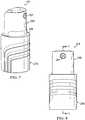
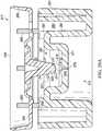
- a reduced pressure treatment apparatus, or reduced pressure source 211is a manually-actuated pump having a first, or outer barrel 215 and a second, or inner barrel 219.
- the first barrel 215includes a passage 223 (see FIG. 9 ) having a closed end and an open end.
- the passage 223may be defined by a substantially cylindrical wall.
- the passage 223slidingly receives the second barrel 219 through the open end of the first barrel 215, and the second barrel 219 is movable between an extended position and a compressed position. While the first and second barrels are illustrated as having substantially cylindrical shapes, the shapes of the barrels could be any other shape that permits operation of the device.
- the reduced pressure source 211In the extended position, the reduced pressure source 211 is discharged and does not actively deliver or supply a reduced pressure. In the compressed position, the reduced pressure source 211 is primed or charged, and the reduced pressure source 211 is capable of delivering a reduced pressure.
- An outlet port 227is provided on the second barrel 219 and is adapted for fluid communication with a delivery tube or other conduit, which may be similar to delivery tube 135, such that reduced pressure generated by the reduced pressure source 211 may be delivered to the tissue site.
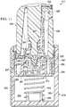
- the reduced pressure source 211further includes a barrel ring 229, a piston 231, and a seal 235.
- the barrel ring 229is positioned at the open end of the first barrel 215 to circumscribe the second barrel 219.
- the barrel ring 229eliminates large gaps between the first barrel 215 and the second barrel 219 at the open end of the first barrel 215.
- the first barrel 215includes a protrusion 239 extending from the closed end of the first barrel 215 into the passage 223.
- a piston spring 243 or other biasing memberis positioned within the passage 223 and is received at one end of the piston spring 243 by the protrusion 239.
- the protrusion 239reduces lateral movement of the piston spring 243 within the passage 223.
- An opposite end of the piston spring 243is received against the piston 231.
- the piston spring 243biases the piston 231, the seal 235, and the second barrel 219 toward the extended position.
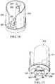
- the piston 231includes an outer wall 247 and an inner wall 251 joined by an outer floor 253.
- An annulus 255is defined between the outer wall 247 and the inner wall 251, and a plurality of radial supports 259 are positioned between the outer wall 247 and the inner wall 251 in the annulus 255.
- the radial supports 259provide additional rigidity to the piston 231, yet the presence of the annulus 255 as well as the sizes and spacing of the radial supports 259 within the annulus 255 reduces the weight of the piston 231 as compared to a single-wall piston that includes no annulus.
- either piston designwould be suitable for the reduced pressure source described herein.
- a plurality of guides 263is disposed on the piston 231, and in one embodiment, one of the guides 263 is disposed on each radial support 259. As described in more detail herein, the guides 263 serve to align the piston 231 relative to the seal 235 and the second barrel 219. The guides 263 further serve to secure the piston 231 to the second barrel 219 by means of a friction fit.
- the piston 231further includes an inner bowl 267 that is defined by the inner wall 251 and an inner floor 271.
- the inner floor 271may be two-tiered or multi-tiered as illustrated in FIG. 11 , but the inner floor 271 may instead be single-tiered and/or substantially planar.
- the inner floor 271may be positioned such that a recess 273 is defined beneath the inner floor 271 to receive an end of the piston spring 243 (see FIGS. 11 and 13 ).
- a regulator passage 275passes through the inner floor 271.
- a valve seat 279may be positioned in the inner bowl 267 near the regulator passage 275 such that fluid communication through the regulator passage 275 may be selectively controlled by selective engagement of the valve seat 279 with a valve body (described in more detail with reference to FIG. 15 ).
- a well 283is positioned in the annulus 255 of the piston 231, and a channel 287 is fluidly connected between the well 283 and the inner bowl 267.
- the channel 287allows fluid communication between the well 283 and the inner bowl 267.
- the seal 235includes a central portion 291 that is circumscribed by a skirt portion 295.
- a plurality of guidance apertures 299are disposed in the central portion 291 to receive the guides 263 of the piston 231 when the reduced pressure source 211 is assembled.
- a communication aperture 301is similarly disposed in the central portion 291, and in one embodiment, the communication aperture 301 is radially spaced an equal distance from a center of the seal as the guidance apertures 299.
- the communication aperture 301permits fluid communication through the central portion 291 of the seal 235 and with the well 283 of the piston 231 upon assembly.
- the skirt portion 295 of the seal 235extends axially and radially outward from the central portion 291. As illustrated in FIG. 11 , the radially-outward-extending skirt portion 295 engages an inner surface 305 of the first barrel 215 to permit unidirectional fluid communication past the seal 235. In other words, the skirt portion 295 of the seal 235 allows fluid to flow past the skirt portion 295 when the fluid flow is directed from the side of the seal 235 on which the piston 231 is disposed toward the opposite side of the seal 235. The skirt portion 295, however, substantially prevents fluid flow in the opposite direction. While the skirt portion of the seal effectively controls fluid communication past the skirt portion 295, a valve member such as, for example, a check valve or other valve could instead be used to perform this function.
- a valve membersuch as, for example, a check valve or other valve could instead be used to perform this function.
- valve body 303is positioned on the central portion 291 of the seal 235.
- the valve body 303may be cone-shaped with an apex 309 that is adapted to sealingly engage the valve seat 279 of the piston 231.
- the valve body 303is illustrated as being an integral part of the seal 235, the valve body 303 may alternatively be a separate component from the seal 235 that is provided to engage the valve seat 279.
- both the seal 235 and the valve body 303are made from an elastomeric material, which could include without limitation a medical grade silicone. While many different materials may be used to construct, form, or otherwise create the seal 235 and valve body 303, it is preferred that a flexible material be used to improve the sealing properties of the skirt portion 295 with the inner surface 305 and the valve body 303 with the valve seat 279.
- a regulator spring 307is provided to bias the valve body 303 away from the piston 231 and the valve seat 279.
- One end of the regulator spring 307may be positioned concentrically around the valve seat 279 within the inner bowl 267 of the piston 231, while another end of the regulator spring 307 may be positioned around the valve body 303.
- the biasing force provided by the regulator spring 307urges the valve body 303 toward an open position in which fluid communication is permitted through the regulator passage 275.
- the spring 307biases the valve body 303 toward the open position, only the central portion 291 of the seal 235 moves upward due to the flexibility of the seal (see FIG. 20 ).
- the biasing force of the spring 307may move the entire seal 235 toward the open position as illustrated in FIG. 20A .
- the second barrel 219includes a first housing portion 311 and a second housing portion 315.
- the first housing portion 311includes an outer shell 319 having an aperture 323 disposed near an open end of the first housing portion 311.
- a floor 327is integrally formed with or otherwise connected to the outer shell 319 on an end of the first housing portion 311 opposite the open end.
- a passage 331may be centrally disposed in the floor 327.
- a boss 333is integrated with or connected to the first housing portion 311.
- the boss 333includes the outlet port 227, which is physically aligned with the aperture 323 to allow a delivery tube to be fluidly connected to the outlet port 227.
- the boss 323is a ninety degree fluid fitting that permits the outlet port 227 to fluidly communicate with a conduit 335 positioned within the first housing portion 311.
- the conduit 335may be a rigid conduit that is formed from the same or similar material to that of the outer shell, or in one alternative embodiment, the conduit 335 may be flexible.
- a plurality of guidance apertures 337are disposed in the floor 327 of the first housing portion 311.
- the guidance apertures 337receive the guides 263 of the piston 231 to ensure that the second barrel 219 remains aligned with the piston 231.
- a friction fit between the guides 263 and guidance apertures 337assist in securing the relative positions of the piston 231 and the second barrel 219. It should be readily apparent, however, that the piston 231 and the second barrel 219 may be secured by alternative means.
- a communication aperture 338is also disposed in the floor 327 to allow fluid communication with the conduit 335 through the floor 327.
- the second housing portion 315may include an end cap 339 integrally or otherwise connected to a guide 343. Together, the end cap 339 and guide 343 slidingly engage the outer shell 319 of the first housing portion 311 to create a substantially closed second barrel 219 (with the exception of various apertures and passages). While the second barrel 219 may be constructed from fewer components, the existence of the first housing portion 311 and the second housing portion 315 allows easier access within the second barrel 219 and also allows easier assembly of the reduced pressure source 211. Additional advantages regarding the sliding engagement of the first housing portion 311 and the second housing portion 315 are explained in more detail below.
- a shaft 347extends from the end cap 339 and includes an engagement end 349 opposite the end cap 339.
- the shaftWhen the second barrel 219 is assembled, the shaft may be substantially coaxial to a longitudinal axis of the second barrel 219 and extend through the passage 331 in the floor 327 of the first housing portion 311.
- a spring 351is positioned within the second barrel 219 such that one end of the spring 351 bears upon the floor 327 of the first housing portion 311 and another end of the spring 351 bears upon the shaft 347 or another portion of the second housing portion 315.
- the spring 351biases the shaft 347 and other portions of the second housing portion 315 toward a disengaged position (see position of shaft 347 in FIG.
- a charging chamber 355is defined within the first barrel 215 beneath the piston 231.
- a regulated chamber 359is defined within the inner bowl 267 of the piston 231 beneath the seal 235.
- the regulator passage 275allows selective fluid communication between the charging chamber 355 and the regulated chamber 359 depending on the position of the valve body 303.
- the regulated chamber 359fluidly communicates with the well 283 of the piston 231 through the channel 287.
- the well 283is aligned with the communication aperture 301 of the seal 235 and the communication aperture 338 of the first housing portion 311, which allows fluid communication between the well 283 and the conduit 335 and outlet port 227 of the second barrel 219.
- regulator passage 275is illustrated as being disposed within the piston 231, the regulator passage 275 could instead be routed through the wall of the first barrel 215.
- the regulator passage 275could be any conduit that is suitable for allowing fluid communication between the chambers.
- the reduced pressure source 211is capable of being used with other components of a reduced pressure treatment system similar to those of reduced pressure treatment system 100 (see FIG. 1 ).
- the outlet port 227 of the reduced pressure source 211is adapted to be connected to a delivery tube or other conduit that is fluidly connected to a tissue site.
- a fluid canistercould be integrated into the reduced pressure source 211, in one embodiment, the reduced pressure source 211 is not intended to collect wound exudates or other fluids within any internal chamber.
- the reduced pressure source 211may either be used with low-exudating wounds, or an alternative collection system such as an external canister or absorptive dressing may be used to collect fluids.
- the extended position (see FIG. 11 ) and the compressed position (see FIG. 18 ) of the reduced pressure source 211are illustrated.
- the reduced pressure source 211is not “charged” and is thus not capable of delivering reduced pressure to the outlet port 227.
- the second barrel 219is manually compressed into the first barrel 215 by a user such that the reduced pressure source 211 is placed in the compressed position.
- the force exerted by the user on the second barrel 219must be greater than the biasing force provided by the piston spring 243.
- the force being exerted on the second barrel 219 by the useris also transmitted to the seal 235 and piston 231.
- the movement of the second barrel 219, the seal 235, and the piston 231 into the compressed positiondecreases the volume of the charging chamber 355.
- the pressure in the charging chamber 355increases, but air and other gases within the charging chamber 355 are allowed to escape past the skirt portion 295 of the seal 235 due to the increased pressure within the charging chamber 355.
- a reduced pressurethat is greater (i.e., a lower absolute pressure) than the amount of reduced pressure to be supplied to the tissue site. For example, if it is desired to provide 125 mmHg of reduced pressure to the tissue site, it may be desirable to have the charging chamber 355 charged to 150 mmHg of reduced pressure.
- the regulated chamber 359is used to generate the desired therapy pressure that is delivered to the outlet port 227 and the tissue site.
- the upward force on the seal 235(exerted by the increased absolute pressure in the regulated chamber 359 and the biasing force of the regulator spring 307, both against the atmosphere pressure exerted downward on the seal 235) moves the valve body 303 into the open position (see FIG. 20 ), thereby allowing fluid communication between the charging chamber 355 and the regulated chamber 359.
- the charging chamber 355continues to charge the regulated chamber 359 with reduced pressure (i.e., the absolute pressure in the regulated chamber 359 continues to drop) until the reduced pressure in the regulated chamber 359, balanced against the atmospheric pressure above the seal 235, is sufficient to counteract the biasing force of the regulator spring 307 and move the valve body into the closed position (see FIG. 19 ).
- this pressuremay be delivered to the outlet port as detailed previously.
- the reduced pressure source 211When the reduced pressure source 211 is initially connected to a delivery tube and tissue site for treatment, it will likely be necessary to compress the second barrel 219 within the first barrel 215 multiple times. As each compression stroke is completed, the reduced pressure generated within the charging chamber 355 will pull air and any other gases from the delivery tube and the tissue site until the pressure within the tube and at the tissue site begins to approach the desired therapy pressure.
- the reduced pressure source 211As the reduced pressure source 211 is being primed by one or more compressions, it is important that air and other positively-pressurized gases being pushed out of the charging chamber 355 are pushed past the skirt portion 295 of the seal 235 and not into the regulated chamber 359. Positively pressurized gas flow to the regulated chamber 359 may transfer to the delivery tube and the tissue site, which would counteract the reduced pressure that is then being applied to the tissue site. To prevent positively pressurized gas from entering the regulated chamber 359, the shaft 347 is provided to engage the seal 235 and valve body 303.
- the second housing portion 315moves relative to the first housing portion 311 so that the shaft 347 exerts a force on the valve body 303 that holds the valve body 303 in the closed position. Since the shaft 347 remains engaged during the entire compression, or charging stroke of the reduced pressure source 211, the air within the charging chamber 355 is vented past the seal 235 and not into the regulated chamber 359.
- the reduced pressure source 211including the first barrel 215, the second barrel 219, the piston 231, and the seal 235, have been described herein as being cylindrical, it will be readily apparent that all of these components may be any size or shape. Additionally, the relative positions of the valve seat 279 and the valve body 303 may be varied in some embodiments.
- valve body 303can maintain a therapeutic pressure.
- regulated chamber 359may be adapted to compensate for leaks that are less than about 1 L/min.
- valve body 303may not be able to maintain the therapy pressure if a leak exceeds such a limit, which is generally dependent upon the size of the restrictions on the entry and exit sides of the regulated chamber 359.
- the flow leaving regulated chamber 359can be controlled by adjusting the bore size of regulator passage 275, and the flow coming in can be controlled by adjusting the size of the bore of a number of components in the fluid path, such as the conduit 112, tubing adapter 116, or outlet port 227.
- the size of the borescan be balanced such that a flow-induced drop in reduced-pressure in regulated chamber 359 deflects valve body 303, leaving a gap between valve body 303 and regulator passage 275.
- the decrease in reduced pressure in regulated chamber 359may partially open valve body 303.
- the drop in reduced pressuremay partially close valve body 303, but still leave a gap.
- the gap between valve body 303 and regulator passage 275is less than 0.1 mm.
- the bore sizescan be balanced so that valve body 303 remains open if no dressing is connected.
- the bore sizesmay be calibrated such that a flow of air through the gap produces an audible indicator, alerting an operator of an unexpected loss of therapeutic pressure.
- a leak thresholdmay represent a leak rate that is sufficient to interfere with a prescribed therapy, and many applications may have a leak threshold of about 0.8 L/min.
- An audible indicatormay be produced at this threshold if the diameter of regulator passage 275 is in the range of about 1 mm to about 1.5 mm and conduit 112 has a lumen size of about 1.2 mm over a length of about 500 mm to 800 mm.
- the size of the gape.g., the distance between apex 309 and regulator passage 275
- valve body 303 and regulator passage 275may also be designed to accentuate the audible feedback.
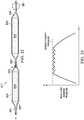
- a reduced pressure treatment system 511includes a reduced pressure treatment apparatus 513 for delivering a reduced pressure to a dressing 515 positioned at a tissue site 517.
- the reduced pressure treatment apparatusincludes a first flexible bladder 521 and a second flexible bladder 523.
- the flexible bladders 521, 523are preferably made from an elastomeric material such as, for example, a silicone polymer, rubber, or another elastomeric material.
- the first flexible bladder 521includes a compressible chamber 527 in which is disposed a biasing member 529.
- the second flexible bladder 523includes a charging chamber 535 in which is disposed a biasing member 537.
- the biasing members 529, 537may be any device that provides a biasing force to resist collapse of the chambers 527, 535.
- the biasing members 529, 537may be a porous foam that allows flow of fluid within or through the chambers 527, 535, but resists collapse when the chambers are exposed to a pressure less than an ambient pressure surrounding the reduced pressure treatment apparatus 513.
- the first flexible bladder 521includes a one-way valve 541 to allow expulsion of air from the compressible chamber 527 when the first flexible bladder is 521 is compressed by a user.
- the one-way valve 541prevents or substantially reduces fluid from entering the compressible chamber 527 through the one-way valve 541. Instead, fluid enters the compressible chamber 527 through a one-way valve 551 positioned between the first flexible bladder 521 and the second flexible bladder 523. This fluid is pulled from the charging chamber 535 into the compressible chamber 527 to create a reduced pressure within the charging chamber 535.
- the first flexible bladder 521may be compressed and allowed to expand several times to create the desired amount of reduced pressure in the charging chamber 535.
- the biasing member 537 in the charging chamber 535is a porous foam that is more resistant to collapse than the biasing member 529 disposed in the compressible chamber 527. This configuration allows the charging chamber 535 to resist collapse such that a greater reduced pressure may be stored in the charging chamber 535.
- the charging chamber 535is positioned in fluid communication with the dressing 515 to deliver a reduced pressure to the tissue site 517.
- a regulator member 561is positioned between the charging chamber 535 and the tissue site 517 to regulate pressure delivered by the charging chamber 535 to the tissue site 517.
- the regulator member 561may be similar to other regulators described herein, or may be any other type of regulator or device capable of regulating pressure. In one embodiment, it is desired that a pressure within the charging chamber 535 be less than the ambient pressure and less than a desired therapy pressure that is to be delivered to the tissue site 517.
- the regulator member 561ensures that pressure delivered to the tissue site 517 does not drop below the desired therapy pressure. If the pressure supplied to the tissue 517 begins to exceed the desired therapy pressure (i.e. more reduced pressure is needed), the regulator opens to allow fluid communication between the charging chamber 535 and the tissue site 517.
- the reduced pressure treatment apparatushas been described as having a charging chamber similar in some respects to other embodiments described herein. While a well-defined regulated chamber has not been described in this particular embodiment, a regulated chamber exists either within the dressing 515 at which regulated pressure is maintained, or within a fluid conduit fluidly connecting the regulator member 561 to the dressing 515.
- a graphis provided that illustrates the changes in pressure over time within a regulated chamber such as the regulated chambers described herein.
- the ability of a charging chamber to recharge the regulated chamberallows the pressure within the regulated chamber to vary little from the desired therapy pressure during operation of the reduced pressure source.
Landscapes
- Health & Medical Sciences (AREA)
- Heart & Thoracic Surgery (AREA)
- Hematology (AREA)
- Engineering & Computer Science (AREA)
- Anesthesiology (AREA)
- Biomedical Technology (AREA)
- Vascular Medicine (AREA)
- Life Sciences & Earth Sciences (AREA)
- Animal Behavior & Ethology (AREA)
- General Health & Medical Sciences (AREA)
- Public Health (AREA)
- Veterinary Medicine (AREA)
- Media Introduction/Drainage Providing Device (AREA)
- External Artificial Organs (AREA)
- Massaging Devices (AREA)
Description
- The subject matter described herein relates generally to reduced pressure treatment systems. More particularly, but without limitation, the subject matter relates to a manually-actuated reduced pressure treatment system having capabilities for providing a regulated pressure to a tissue site and an audible indication of a leak.
- Clinical studies and practice have shown that reducing pressure in proximity to a tissue site can augment and accelerate growth of new tissue at the tissue site. The applications of this phenomenon are numerous, but it has proven particularly advantageous for treating wounds. Regardless of the etiology of a wound, whether trauma, surgery, or another cause, proper care of the wound is important to the outcome. Treatment of wounds with reduced pressure is commonly referred to as "reduced-pressure therapy," but may also be known by other names, including "negative pressure wound therapy," "vacuum-assisted closure," or "vacuum therapy," for example. Reduced-pressure therapy may provide a number of benefits, including migration of epithelial and subcutaneous tissues, improved blood flow, and micro-deformation of tissue at a wound site. Together, these benefits can increase development of granulation tissue and reduce healing times.
- While the clinical benefits of reduced-pressure therapy are widely known, the cost and complexity of reduced-pressure therapy can be a limiting factor in its application, and the development and operation of reduced-pressure systems, components, and processes continues to present significant challenges to manufacturers, healthcare providers, and patients.
WO 2007/067685 A2 describes a wound exudate removal and isolation system with a pump.AU 2009 242 535 A1 US 2011/0098611 A1 describes methods of achieving increased fluid distribution with, and patient kits for, resuscitation systems.- Illustrative embodiments of new and useful systems and methods for reduced-pressure therapy are described herein. One example embodiment is a manually-actuated pump for applying reduced-pressure therapy, which generally comprises a charging chamber, a regulated chamber, and a regulator passage between the charging chamber and the regulated chamber. A valve body is adapted to control fluid communication through the regulator passage, and a regulator spring may be engaged with the valve body to bias the valve body against a differential between a pressure in the regulated chamber and an ambient pressure. The regulator passage may have a bore size adapted to deflect the valve body, leaving a gap between the valve body and the regulator passage to cause an audible indication of a leak above a threshold. The gap in some example embodiments may be less than 0.1 mm, and the bore size preferably has a diameter in a range of about 1 mm to about 1.5 mm. A conduit may also be coupled to the outlet port, and the conduit preferably has a lumen with a diameter of about 1.2 mm.
- Other illustrative embodiments of an apparatus are described having a piston chamber having a closed end, a piston disposed within the piston chamber and being movable between an extended position and a compressed position, a charging chamber disposed between the piston and the closed end, and a regulated chamber. A biasing member may be adapted to bias the piston toward the extended position, and a valve member can be adapted to allow fluid to exit the charging chamber as the piston moves toward the compressed position and to prevent fluid from entering the charging chamber as the piston moves toward the extended position. A regulator member may be provided to regulate fluid communication through a passage between the charging chamber and the regulated chamber, wherein the passage has a bore size adapted to deflect the regulator member cause an audible indication of a leak greater than a predetermined threshold.
- Illustrative embodiments of methods for providing reduced pressure treatment are also described, including methods that store a charging pressure within a charging chamber, deliver a desired therapy pressure from a regulated chamber to a tissue site, reduce the pressure within the regulated chamber by allowing fluid communication between the charging chamber and the regulated chamber when a pressure within the regulated chamber exceeds the desired therapy pressure, and provide an audible indication of a leak.
- Other objects, features, and advantages of the illustrative embodiments will become apparent with reference to the drawings and detailed description that follow.
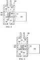
FIG. 1 illustrates a perspective view of a reduced pressure treatment system according to an illustrative embodiment, the reduced pressure treatment system having a reduced pressure pump adapted to deliver a reduced pressure to a dressing positioned at a tissue site;FIG. 2 depicts a cross-sectional front view of the dressing ofFIG. 1 taken at 2-2;FIG. 3 illustrates a schematic of a reduced pressure treatment apparatus according to an illustrative embodiment, the reduced pressure treatment apparatus having a charging chamber, a regulated chamber, and a regulator member, the regulator member being shown in an open position;FIG. 4 depicts a schematic of the reduced pressure treatment apparatus ofFIG. 3 , the regulator member being shown in a closed position;FIG. 5 illustrates a schematic of a piston-driven device for use with the reduced pressure treatment apparatus ofFIG. 3 to charge the charging chamber with a reduced pressure, the piston-driven device having a piston shown in a compressed position;FIG. 6 depicts a schematic of the piston-driven device ofFIG. 5 with the piston shown in an extended position;FIG. 7 illustrates a side perspective view of a reduced pressure treatment apparatus according to an illustrative embodiment;FIG. 8 depicts a front view of the reduced pressure treatment apparatus ofFIG. 7 ;FIG. 9 illustrates an exploded side perspective view of the reduced pressure treatment apparatus ofFIG. 7 ;FIG. 10 depicts an exploded rear perspective view of the reduced pressure treatment apparatus ofFIG. 7 ;FIG. 11 illustrates a cross-sectional side view of the reduced pressure treatment apparatus ofFIG. 8 taken at 11-11, the reduced pressure treatment apparatus shown in an extended position;FIG. 12 depicts a top-rear perspective view of a piston of the reduced pressure treatment apparatus ofFIG. 7 ;FIG. 13 illustrates a bottom-rear perspective view of the piston ofFIG. 12 ;FIG. 14 depicts a top-rear perspective view of a seal of the reduced pressure treatment apparatus ofFIG. 7 ;FIG. 15 illustrates a bottom-rear perspective view of the seal ofFIG. 14 ;FIG. 16 depicts a top-rear perspective view of a second barrel of the reduced pressure treatment apparatus ofFIG. 7 ;FIG. 17 illustrates a bottom-rear perspective view of the second barrel ofFIG. 16 ;FIG. 18 depicts a cross-sectional side view of the reduced pressure treatment apparatus ofFIG. 7 , the reduced pressure treatment apparatus shown in a compressed position;FIG. 19 illustrates an enlarged cross-sectional view of the reduced pressure treatment apparatus ofFIG. 18 , the reduced pressure treatment apparatus having a valve body shown in a closed position;FIG. 20 depicts an enlarged cross-sectional view of the reduced pressure treatment apparatus ofFIG. 19 with the valve body shown in an open position;FIG. 20A depicts an enlarged cross-sectional view, similar to that ofFIG. 20 , of a reduced pressure treatment apparatus according to an illustrative embodiment;FIG. 21 illustrates a perspective view of a reduced pressure treatment apparatus according to an illustrative embodiment;FIG. 22 depicts a cross-sectional side view of the reduced pressure treatment apparatus ofFIG. 21 taken at 22-22; andFIG. 23 illustrates a graph of regulated chamber pressure vs. time for a reduced pressure treatment apparatus.- New and useful systems, methods, and apparatuses associated with providing reduced-pressure therapy are set forth in the appended claims. Objectives, advantages, and a preferred mode of making and using the systems, methods, and apparatuses may be understood best by reference to the following detailed description in conjunction with the accompanying drawings. The description provides information that enables a person skilled in the art to make and use the claimed subject matter, but may omit certain details already well-known in the art. Moreover, descriptions of various alternatives using terms such as "or" do not necessarily require mutual exclusivity unless clearly required by the context. The claimed subject matter may also encompass alternative embodiments, variations, and equivalents not specifically described in detail. The following detailed description should therefore be taken as illustrative and not limiting.
- The example embodiments may also be described herein in the context of a reduced-pressure therapy applications, but many of the features and advantages are readily applicable to other environments and industries. Spatial relationships between various elements or to the spatial orientation of various elements may be described as depicted in the attached drawings. In general, such relationships or orientations assume a frame of reference consistent with or relative to a patient in a position to receive reduced-pressure therapy. However, as should be recognized by those skilled in the art, this frame of reference is merely a descriptive expedient rather than a strict prescription.
- The term "reduced pressure" as used herein generally refers to a pressure less than the ambient pressure at a tissue site that is being subjected to treatment. In most cases, this reduced pressure will be less than the atmospheric pressure at which the patient is located. Alternatively, the reduced pressure may be less than a hydrostatic pressure associated with tissue at the tissue site. Although the terms "vacuum" and "negative pressure" may be used to describe the pressure applied to the tissue site, the actual pressure reduction applied to the tissue site may be significantly less than the pressure reduction normally associated with a complete vacuum. Reduced pressure may initially generate fluid flow in the area of the tissue site. As the hydrostatic pressure around the tissue site approaches the desired reduced pressure, the flow may subside, and the reduced pressure is then maintained. Unless otherwise indicated, values of pressure stated herein are gauge pressures. Similarly, references to increases in reduced pressure typically refer to a decrease in absolute pressure, while decreases in reduced pressure typically refer to an increase in absolute pressure.
- The term "tissue site" as used herein refers to a wound or defect located on or within any tissue, including but not limited to, bone tissue, adipose tissue, muscle tissue, neural tissue, dermal tissue, vascular tissue, connective tissue, cartilage, tendons, or ligaments. The term "tissue site" may further refer to areas of any tissue that are not necessarily wounded or defective, but are instead areas in which it is desired to add or promote the growth of additional tissue. For example, reduced pressure tissue treatment may be used in certain tissue areas to grow additional tissue that may be harvested and transplanted to another tissue location.
- In general, reduced-pressure therapy can be beneficial for wounds of all severity, but the cost and complexity of reduced-pressure therapy systems often limit the application of reduced-pressure therapy to large, highly-exudating wounds present on patients undergoing acute or chronic care, as well as other severe wounds that are not readily susceptible to healing without application of reduced pressure. For example, the complexity of conventional reduced-pressure therapy systems can limit the ability of a person with little or no specialized knowledge from administering reduced-pressure therapy. The size of many reduced-pressure therapy systems may also impair mobility. Many reduced-pressure therapy systems also require careful cleaning after each treatment, and may require electrical components or other powered devices to supply the reduced pressure for treatment.
- Eliminating power requirements can increase mobility, and generally reduce cost, as well. For example, a manually-actuated or manually-charged pump can be used as a source of reduced pressure instead of an electrically-powered pump. However, leaks in a dressing can gradually erode energy stored in pump. Large leaks are also common when a dressing is first applied. A manually-actuated reduced-pressure therapy system can be particularly sensitive to leaks because the capacity of such a system to generate reduced pressure is typically more limited than electrically-powered pumps. The presence of a leak at a dressing can quickly dissipate the therapeutic pressure generated by a pump.
- As described herein, a reduced-
pressure treatment system 100 can overcome these shortcomings and others by providing audible feedback of flow indicative of a leak. Referring toFIGS. 1 and2 , a reducedpressure treatment system 100 according to an illustrative embodiment includes a reduced pressure dressing 104 positioned at atissue site 108 of a patient. The reduced pressure dressing 104 is fluidly connected to a reducedpressure source 110 by aconduit 112. Theconduit 112 may fluidly communicate with the reduced pressure dressing 104 through atubing adapter 116. In the embodiment illustrated inFIG. 1 , the reducedpressure source 110 is a manually-actuated pump such as the regulated pressure pumps described herein. In another implementation, the reducedpressure source 110 may include pressure regulation capabilities but may initially be charged or re-charged to a selected reduced pressure by a reduced pressure or vacuum pump that is driven by an electric motor. In still another embodiment, the reducedpressure source 110 may be charged to the selected reduced pressure by a wall suction port such as are available in hospitals and other medical facilities. - The reduced
pressure source 110 may be housed within or used in conjunction with a reduced pressure treatment unit (not shown), which may also contain sensors, processing units, alarm indicators, memory, databases, software, display units, and user interfaces that further facilitate the application of reduced pressure treatment to thetissue site 108. In one example, a sensor or switch (not shown) may be disposed at or near the reducedpressure source 110 to determine a source pressure generated by the reducedpressure source 110. The sensor may communicate with a processing unit that monitors and controls the reduced pressure that is delivered by the reducedpressure source 110. Delivery of reduced pressure to the reduced pressure dressing 104 andtissue site 108 encourages new tissue growth by maintaining drainage of exudate from the tissue site, increasing blood flow to tissues surrounding the tissue site, and creating microstrain at the tissue site. - The reduced pressure dressing 104 includes a
distribution manifold 120 adapted to be positioned at thetissue site 108, and aseal layer 122 to seal the reduced pressure dressing 104 around thetissue site 108. Acover 124, or drape, is positioned over thedistribution manifold 120 and the seal layer to maintain reduced pressure beneath thecover 124 at the tissue site. Thecover 124 may extend beyond a perimeter of the tissue site and may include an adhesive or bonding agent on thecover 124 to secure the cover to tissue adjacent the tissue site. In one embodiment, the adhesive disposed oncover 124 may be used in lieu of theseal layer 122, however, theseal layer 122 may be used in conjunction with the adhesive of thecover 124 to improve sealing of thecover 124 at thetissue site 108. In another embodiment, theseal layer 122 may be used in lieu of adhesive disposed oncover 124. - The
distribution manifold 120 of the reduced pressure dressing 104 is adapted to contact thetissue site 108. Thedistribution manifold 120 may be partially or fully in contact with thetissue site 108 being treated by the reduced pressure dressing 104. When thetissue site 108 is a wound, thedistribution manifold 120 may partially or fully fill the wound. - The
distribution manifold 120 may be any size, shape, or thickness depending on a variety of factors, such as the type of treatment being implemented or the nature and size of thetissue site 108. For example, the size and shape of thedistribution manifold 120 may be customized by a user to cover a particular portion of thetissue site 108, or to fill or partially fill thetissue site 108. Although thedistribution manifold 120 illustrated inFIG. 3 has a square shape, thedistribution manifold 120 may be shaped as a circle, oval, polygon, an irregular shape, or any other shape. - In one illustrative embodiment, the
distribution manifold 120 is a foam material that distributes reduced pressure to thetissue site 108 when thedistribution manifold 120 is in contact with or near thetissue site 108. The foam material may be either hydrophobic or hydrophilic. In one non-limiting example, thedistribution manifold 120 is an open-cell, reticulated polyurethane foam such as GranuFoam® dressing available from Kinetic Concepts, Inc. of San Antonio, Texas. - In the example in which the
distribution manifold 120 is made from a hydrophilic material, thedistribution manifold 120 also functions to wick fluid away from thetissue site 108, while continuing to provide reduced pressure to thetissue site 108 as a manifold. The wicking properties of thedistribution manifold 120 draw fluid away from thetissue site 108 by capillary flow or other wicking mechanisms. An example of a hydrophilic foam is a polyvinyl alcohol, open-cell foam such as V.A.C. WhiteFoam® dressing available from Kinetic Concepts, Inc. of San Antonio, Texas. Other hydrophilic foams may include those made from polyether. Other foams that may exhibit hydrophilic characteristics include hydrophobic foams that have been treated or coated to provide hydrophilicity. - The
distribution manifold 120 may further promote granulation at thetissue site 108 when a reduced pressure is applied through the reduced pressure dressing 104. For example, any or all of the surfaces of thedistribution manifold 120 may have an uneven, coarse, or jagged profile that causes microstrains and stresses at thetissue site 108 when reduced pressure is applied through thedistribution manifold 120. These microstrains and stresses have been shown to increase new tissue growth. - In one embodiment, the
distribution manifold 120 may be constructed from bioresorbable materials that do not have to be removed from a patient's body following use of the reduced pressure dressing 104. Suitable bioresorbable materials may include, without limitation, a polymeric blend of polylactic acid (PLA) and polyglycolic acid (PGA). The polymeric blend may also include without limitation polycarbonates, polyfumarates, and capralactones. Thedistribution manifold 120 may further serve as a scaffold for new cell-growth, or a scaffold material may be used in conjunction with thedistribution manifold 120 to promote cell-growth. A scaffold is a substance or structure used to enhance or promote the growth of cells or formation of tissue, such as a three-dimensional porous structure that provides a template for cell growth. Illustrative examples of scaffold materials include calcium phosphate, collagen, PLA/PGA, coral hydroxy apatites, carbonates, or processed allograft materials. - Referring to
FIGS. 3 and 4 , a reducedpressure treatment apparatus 150, or reduced pressure pump, or reduced pressure source, is schematically illustrated and includes a chargingchamber 154 fluidly connected by apassage 156, or conduit, to aregulated chamber 158. Aregulator member 162 is operably associated with thepassage 156 to selectively allow or prevent fluid communication between the chargingchamber 154 and theregulated chamber 158. In the embodiment illustrated inFIGS. 3 and 4 , theregulator member 162 includes apiston 164 that is disposed within theregulated chamber 158. Theregulator member 162 further includes aregulator spring 166 to bias thepiston 164 toward an open position as illustrated inFIG. 3 . In the open position, thepiston 164 allows fluid communication through thepassage 156. In a closed position (shown inFIG. 4 ), thepiston 164 prevents or at least substantially reduces fluid communication through thepassage 156. - As previously noted, the charging
chamber 154 is fluidly connected to theregulated chamber 158 bypassage 156. The chargingchamber 154 may include aninlet 170 for introduction of a reduced pressure to the chargingchamber 154, or as explained below, the chargingchamber 154 may by operably associated with a piston-driven or other device to charge the chargingchamber 154 with the reduced pressure. The chargingchamber 154 is well suited to receive the reduced pressure from a device that is manually-actuated, or alternatively that is powered by electrical or other means. - The
regulated chamber 158 is fluidly connected by aconduit 172 to adressing 174. In one embodiment, theconduit 172 and dressing 174 may be similar toconduit 112 and dressing 104. When reduced pressure treatment is applied to the dressing 174 and a tissue site, it is desired to deliver a reduced pressure to dressing 174 that is about equal to a desired therapy pressure. To accomplish this, the chargingchamber 154 stores a first pressure that is less than an ambient pressure. Theregulated chamber 158 stores a second pressure that is also less than the ambient pressure. The first pressure stored in the chargingchamber 154 is less than the second pressure stored in theregulated chamber 158. - When the second pressure is less than or equal to the desired therapy pressure, a counteracting force on the piston is able to overcome a biasing force exerted by the
regulator spring 166 on thepiston 164. The counteracting force on the piston is a result of a pressure differential across opposite sides of thepiston 164. On afirst side 176 of thepiston 164, the ambient pressure (e.g. atmospheric pressure) surrounding the reducedpressure treatment apparatus 150 acts on thepiston 164. On asecond side 178 of thepiston 164, the second pressure within theregulated chamber 158 acts on the piston. Since the second pressure is less than the ambient pressure, the counteracting force acts on thefirst side 176 of thepiston 164 against the biasing force of theregulator spring 166. When the second pressure in theregulated chamber 158 is less than or equal to the desired therapy pressure, thepiston 164 moves to and remains in the closed position. - If the second pressure in the
regulated chamber 158 rises above (i.e. exceeds) the desired therapy pressure, possibly due to fluid leaks at the dressing 174 or within the reducedpressure treatment apparatus 150, thepiston 164 is biased back to the open position by theregulator spring 166. In the open position, fluid communication is allowed between the chargingchamber 154 and theregulated chamber 158. Since the first pressure in the chargingchamber 154 is less than the second pressure in theregulated chamber 158, the second pressure in theregulated chamber 158 drops until the desired therapy pressure is reached, at which point thepiston 164 again moves to the closed position. In one embodiment, the first pressure stored in the chargingchamber 154 is about -150 mm Hg, and the desired therapy pressure is about -125 mm Hg. - If a dressing has a small leak,
regulator member 162 can maintain the therapy pressure. However,regulator member 162 may not be able to maintain the therapy pressure if a leak exceeds a certain tolerance, which is dependent upon the size of the restrictions on the entry and exit sides of theregulated chamber 158. For example,passage 156 andconduit 172 may be sized such that a leak exceeding a threshold causesregulator member 162 to remain partially open with a gap betweenregulator member 162 andpassage 156 that allows a steady flow of air throughpassage 156 andconduit 172. Moreover, the sizes ofpassage 156 andconduit 172 may be calibrated such that the flow of air through the gap causes an audible note, alerting an operator of an unexpected loss of therapeutic pressure. - Referring to
FIGS. 5 and 6 , a piston-drivendevice 180 is provided for charging a chargingchamber 182 similar to chargingchamber 154. The piston-drivendevice 180 includes apiston 184 disposed within the chargingchamber 182. Thispiston 184 is capable of reciprocal movement between a compressed position (seeFIG. 5 ) and an extended position (see.FIG. 6 ). Apiston spring 188 or other biasing member is operably associated within thepiston 184 to bias thepiston 184 toward the extended position. - To charge the charging
chamber 182, thepiston 184 is moved to the compressed position. Aseal 190 or other valve member allows fluid within the chargingchamber 182 to exit the chargingchamber 182 as a volume of the chargingchamber 182 decreases. After moving thepiston 184 to the compressed position, thepiston spring 188 attempts to return thepiston 184 to the extended position. As the volume of the chargingchamber 182 increases, theseal 190 prevents fluid from entering the chargingchamber 182 past theseal 190, which results in a pressure drop within the chargingchamber 182. After thepiston 184 has moved completely to the extended position, thepiston 184 may be moved again to the compressed position to recharge the chargingchamber 182 with a reduced pressure. - The piston-driven
device 180 may be manually-actuated by a user compressing thepiston 184. Alternatively, thepiston 184 may be actuated by an electrical, hydraulic, or pneumatic actuator. For all of the charging chambers described herein, it should be noted that reduced pressure may be supplied to the charging chamber by manual or electrically powered means. - Referring to
FIGS. 7 and 8 , a reduced pressure treatment apparatus, or reducedpressure source 211 according to an illustrative embodiment is a manually-actuated pump having a first, orouter barrel 215 and a second, orinner barrel 219. Thefirst barrel 215 includes a passage 223 (seeFIG. 9 ) having a closed end and an open end. Thepassage 223 may be defined by a substantially cylindrical wall. Thepassage 223 slidingly receives thesecond barrel 219 through the open end of thefirst barrel 215, and thesecond barrel 219 is movable between an extended position and a compressed position. While the first and second barrels are illustrated as having substantially cylindrical shapes, the shapes of the barrels could be any other shape that permits operation of the device. - In the extended position, the reduced
pressure source 211 is discharged and does not actively deliver or supply a reduced pressure. In the compressed position, the reducedpressure source 211 is primed or charged, and the reducedpressure source 211 is capable of delivering a reduced pressure. Anoutlet port 227 is provided on thesecond barrel 219 and is adapted for fluid communication with a delivery tube or other conduit, which may be similar to delivery tube 135, such that reduced pressure generated by the reducedpressure source 211 may be delivered to the tissue site. - Referring to
FIGS. 9-11 , the reducedpressure source 211 further includes abarrel ring 229, apiston 231, and aseal 235. Thebarrel ring 229 is positioned at the open end of thefirst barrel 215 to circumscribe thesecond barrel 219. Thebarrel ring 229 eliminates large gaps between thefirst barrel 215 and thesecond barrel 219 at the open end of thefirst barrel 215. When the reducedpressure source 211 is assembled, thepiston 231 and seal 235 are slidingly received within thepassage 223 of thefirst barrel 215. Both thepiston 231 and theseal 235 are positioned in thepassage 223 between thesecond barrel 219 and the closed end of thefirst barrel 215, theseal 235 being positioned between thesecond barrel 219 and thepiston 231. - Referring more specifically to
FIG. 11 , thefirst barrel 215 includes aprotrusion 239 extending from the closed end of thefirst barrel 215 into thepassage 223. Apiston spring 243 or other biasing member is positioned within thepassage 223 and is received at one end of thepiston spring 243 by theprotrusion 239. Theprotrusion 239 reduces lateral movement of thepiston spring 243 within thepassage 223. An opposite end of thepiston spring 243 is received against thepiston 231. Thepiston spring 243 biases thepiston 231, theseal 235, and thesecond barrel 219 toward the extended position. - Referring again to
FIGS. 9-11 , but also toFIGS. 12 and 13 , thepiston 231 includes anouter wall 247 and aninner wall 251 joined by anouter floor 253. Anannulus 255 is defined between theouter wall 247 and theinner wall 251, and a plurality ofradial supports 259 are positioned between theouter wall 247 and theinner wall 251 in theannulus 255. The radial supports 259 provide additional rigidity to thepiston 231, yet the presence of theannulus 255 as well as the sizes and spacing of the radial supports 259 within theannulus 255 reduces the weight of thepiston 231 as compared to a single-wall piston that includes no annulus. However, it should be apparent that either piston design would be suitable for the reduced pressure source described herein. - A plurality of
guides 263 is disposed on thepiston 231, and in one embodiment, one of theguides 263 is disposed on eachradial support 259. As described in more detail herein, theguides 263 serve to align thepiston 231 relative to theseal 235 and thesecond barrel 219. Theguides 263 further serve to secure thepiston 231 to thesecond barrel 219 by means of a friction fit. - The
piston 231 further includes aninner bowl 267 that is defined by theinner wall 251 and aninner floor 271. In one embodiment, theinner floor 271 may be two-tiered or multi-tiered as illustrated inFIG. 11 , but theinner floor 271 may instead be single-tiered and/or substantially planar. Theinner floor 271 may be positioned such that arecess 273 is defined beneath theinner floor 271 to receive an end of the piston spring 243 (seeFIGS. 11 and13 ). Aregulator passage 275 passes through theinner floor 271. Avalve seat 279 may be positioned in theinner bowl 267 near theregulator passage 275 such that fluid communication through theregulator passage 275 may be selectively controlled by selective engagement of thevalve seat 279 with a valve body (described in more detail with reference toFIG. 15 ). - A well 283 is positioned in the
annulus 255 of thepiston 231, and achannel 287 is fluidly connected between the well 283 and theinner bowl 267. Thechannel 287 allows fluid communication between the well 283 and theinner bowl 267. - Referring still to
FIGS. 9-11 , but also toFIGS. 14 and 15 , theseal 235 includes acentral portion 291 that is circumscribed by askirt portion 295. A plurality ofguidance apertures 299 are disposed in thecentral portion 291 to receive theguides 263 of thepiston 231 when the reducedpressure source 211 is assembled. Acommunication aperture 301 is similarly disposed in thecentral portion 291, and in one embodiment, thecommunication aperture 301 is radially spaced an equal distance from a center of the seal as theguidance apertures 299. Thecommunication aperture 301 permits fluid communication through thecentral portion 291 of theseal 235 and with the well 283 of thepiston 231 upon assembly. - The
skirt portion 295 of theseal 235 extends axially and radially outward from thecentral portion 291. As illustrated inFIG. 11 , the radially-outward-extendingskirt portion 295 engages aninner surface 305 of thefirst barrel 215 to permit unidirectional fluid communication past theseal 235. In other words, theskirt portion 295 of theseal 235 allows fluid to flow past theskirt portion 295 when the fluid flow is directed from the side of theseal 235 on which thepiston 231 is disposed toward the opposite side of theseal 235. Theskirt portion 295, however, substantially prevents fluid flow in the opposite direction. While the skirt portion of the seal effectively controls fluid communication past theskirt portion 295, a valve member such as, for example, a check valve or other valve could instead be used to perform this function. - As illustrated in more detail in
FIGS. 11 and15 , avalve body 303 is positioned on thecentral portion 291 of theseal 235. Although valve bodies of many types, shapes and sizes may be used, thevalve body 303 may be cone-shaped with an apex 309 that is adapted to sealingly engage thevalve seat 279 of thepiston 231. While thevalve body 303 is illustrated as being an integral part of theseal 235, thevalve body 303 may alternatively be a separate component from theseal 235 that is provided to engage thevalve seat 279. - In one embodiment, both the
seal 235 and thevalve body 303 are made from an elastomeric material, which could include without limitation a medical grade silicone. While many different materials may be used to construct, form, or otherwise create theseal 235 andvalve body 303, it is preferred that a flexible material be used to improve the sealing properties of theskirt portion 295 with theinner surface 305 and thevalve body 303 with thevalve seat 279. - Referring more specifically to
FIG. 11 , aregulator spring 307 is provided to bias thevalve body 303 away from thepiston 231 and thevalve seat 279. One end of theregulator spring 307 may be positioned concentrically around thevalve seat 279 within theinner bowl 267 of thepiston 231, while another end of theregulator spring 307 may be positioned around thevalve body 303. The biasing force provided by theregulator spring 307 urges thevalve body 303 toward an open position in which fluid communication is permitted through theregulator passage 275. In one embodiment, when thespring 307 biases thevalve body 303 toward the open position, only thecentral portion 291 of theseal 235 moves upward due to the flexibility of the seal (seeFIG. 20 ). In another embodiment, the biasing force of thespring 307 may move theentire seal 235 toward the open position as illustrated inFIG. 20A . - Referring again to
FIGS. 9-11 , but also toFIGS. 16 and 17 , thesecond barrel 219 includes afirst housing portion 311 and asecond housing portion 315. Thefirst housing portion 311 includes anouter shell 319 having anaperture 323 disposed near an open end of thefirst housing portion 311. Afloor 327 is integrally formed with or otherwise connected to theouter shell 319 on an end of thefirst housing portion 311 opposite the open end. Apassage 331 may be centrally disposed in thefloor 327. Aboss 333 is integrated with or connected to thefirst housing portion 311. Theboss 333 includes theoutlet port 227, which is physically aligned with theaperture 323 to allow a delivery tube to be fluidly connected to theoutlet port 227. In one embodiment, theboss 323 is a ninety degree fluid fitting that permits theoutlet port 227 to fluidly communicate with aconduit 335 positioned within thefirst housing portion 311. Theconduit 335 may be a rigid conduit that is formed from the same or similar material to that of the outer shell, or in one alternative embodiment, theconduit 335 may be flexible. - Referring more specifically to
FIG. 17 , a plurality ofguidance apertures 337 are disposed in thefloor 327 of thefirst housing portion 311. When the reducedpressure source 211 is assembled, theguidance apertures 337 receive theguides 263 of thepiston 231 to ensure that thesecond barrel 219 remains aligned with thepiston 231. A friction fit between theguides 263 andguidance apertures 337 assist in securing the relative positions of thepiston 231 and thesecond barrel 219. It should be readily apparent, however, that thepiston 231 and thesecond barrel 219 may be secured by alternative means. Acommunication aperture 338 is also disposed in thefloor 327 to allow fluid communication with theconduit 335 through thefloor 327. - The
second housing portion 315 may include anend cap 339 integrally or otherwise connected to aguide 343. Together, theend cap 339 and guide 343 slidingly engage theouter shell 319 of thefirst housing portion 311 to create a substantially closed second barrel 219 (with the exception of various apertures and passages). While thesecond barrel 219 may be constructed from fewer components, the existence of thefirst housing portion 311 and thesecond housing portion 315 allows easier access within thesecond barrel 219 and also allows easier assembly of the reducedpressure source 211. Additional advantages regarding the sliding engagement of thefirst housing portion 311 and thesecond housing portion 315 are explained in more detail below. - A
shaft 347 extends from theend cap 339 and includes anengagement end 349 opposite theend cap 339. When thesecond barrel 219 is assembled, the shaft may be substantially coaxial to a longitudinal axis of thesecond barrel 219 and extend through thepassage 331 in thefloor 327 of thefirst housing portion 311. Aspring 351 is positioned within thesecond barrel 219 such that one end of thespring 351 bears upon thefloor 327 of thefirst housing portion 311 and another end of thespring 351 bears upon theshaft 347 or another portion of thesecond housing portion 315. Thespring 351 biases theshaft 347 and other portions of thesecond housing portion 315 toward a disengaged position (see position ofshaft 347 inFIG. 11 ) in which theengagement end 349 of theshaft 347 does not bear upon theseal 235 orvalve body 303. The sliding relationship and engagement between the first andsecond housing portions second housing portion 315 to an engaged position. In the engaged position, the engagement end 345 of theshaft 347 bears upon theseal 235 above the valve body 303 (seeFIG. 18 ), which forces thevalve body 303 against thevalve seat 279, thereby preventing fluid communication through theregulator passage 275. - When the reduced
pressure source 211 is assembled, as illustrated inFIG. 11 , a chargingchamber 355 is defined within thefirst barrel 215 beneath thepiston 231. Aregulated chamber 359 is defined within theinner bowl 267 of thepiston 231 beneath theseal 235. Theregulator passage 275 allows selective fluid communication between the chargingchamber 355 and theregulated chamber 359 depending on the position of thevalve body 303. Theregulated chamber 359 fluidly communicates with the well 283 of thepiston 231 through thechannel 287. The well 283 is aligned with thecommunication aperture 301 of theseal 235 and thecommunication aperture 338 of thefirst housing portion 311, which allows fluid communication between the well 283 and theconduit 335 andoutlet port 227 of thesecond barrel 219. - While the
regulator passage 275 is illustrated as being disposed within thepiston 231, theregulator passage 275 could instead be routed through the wall of thefirst barrel 215. Theregulator passage 275 could be any conduit that is suitable for allowing fluid communication between the chambers. - In operation, the reduced
pressure source 211 is capable of being used with other components of a reduced pressure treatment system similar to those of reduced pressure treatment system 100 (seeFIG. 1 ). Theoutlet port 227 of the reducedpressure source 211 is adapted to be connected to a delivery tube or other conduit that is fluidly connected to a tissue site. Although a fluid canister could be integrated into the reducedpressure source 211, in one embodiment, the reducedpressure source 211 is not intended to collect wound exudates or other fluids within any internal chamber. In one embodiment, the reducedpressure source 211 may either be used with low-exudating wounds, or an alternative collection system such as an external canister or absorptive dressing may be used to collect fluids. - Referring to
FIGS. 11 and18 , the extended position (seeFIG. 11 ) and the compressed position (seeFIG. 18 ) of the reducedpressure source 211 are illustrated. In the extended position, the reducedpressure source 211 is not "charged" and is thus not capable of delivering reduced pressure to theoutlet port 227. To prime the reducedpressure source 211, thesecond barrel 219 is manually compressed into thefirst barrel 215 by a user such that the reducedpressure source 211 is placed in the compressed position. The force exerted by the user on thesecond barrel 219 must be greater than the biasing force provided by thepiston spring 243. As thesecond barrel 219 compresses within thefirst barrel 215 and moves toward the closed end of thefirst barrel 215, the force being exerted on thesecond barrel 219 by the user is also transmitted to theseal 235 andpiston 231. The movement of thesecond barrel 219, theseal 235, and thepiston 231 into the compressed position decreases the volume of the chargingchamber 355. As the volume of the chargingchamber 355 decreases, the pressure in the chargingchamber 355 increases, but air and other gases within the chargingchamber 355 are allowed to escape past theskirt portion 295 of theseal 235 due to the increased pressure within the chargingchamber 355. - When the user releases the compressive force exerted upon the
second barrel 219, the biasing force exerted by thepiston spring 243 on thepiston 231 moves thepiston 231, theseal 235, and thesecond barrel 219 toward the extended position. As this movement occurs, the volume of the chargingchamber 355 increases. Since theskirt portion 295 of theseal 235 allows only unidirectional flow, air and other gases are not permitted to enter the chargingchamber 355 past theskirt portion 295. A resulting drop in pressure (i.e., a generation of reduced pressure) occurs within the chargingchamber 355 as the volume increases. The amount of reduced pressure generated within the chargingchamber 355 is dependent on the spring constant of thepiston spring 243 and the integrity of theseal 235. In one embodiment, it is desired to generate a reduced pressure that is greater (i.e., a lower absolute pressure) than the amount of reduced pressure to be supplied to the tissue site. For example, if it is desired to provide 125 mmHg of reduced pressure to the tissue site, it may be desirable to have the chargingchamber 355 charged to 150 mmHg of reduced pressure. - The
regulated chamber 359 is used to generate the desired therapy pressure that is delivered to theoutlet port 227 and the tissue site. When the reduced pressure within the chargingchamber 355 is greater than the reduced pressure within theregulated chamber 359 and when the reduced pressure in theregulated chamber 359 is less than the desired therapy pressure, the upward force on the seal 235 (exerted by the increased absolute pressure in theregulated chamber 359 and the biasing force of theregulator spring 307, both against the atmosphere pressure exerted downward on the seal 235) moves thevalve body 303 into the open position (seeFIG. 20 ), thereby allowing fluid communication between the chargingchamber 355 and theregulated chamber 359. The chargingchamber 355 continues to charge theregulated chamber 359 with reduced pressure (i.e., the absolute pressure in theregulated chamber 359 continues to drop) until the reduced pressure in theregulated chamber 359, balanced against the atmospheric pressure above theseal 235, is sufficient to counteract the biasing force of theregulator spring 307 and move the valve body into the closed position (seeFIG. 19 ). When theregulated chamber 359 is charged with the desired therapy pressure, this pressure may be delivered to the outlet port as detailed previously. - When the reduced
pressure source 211 is initially connected to a delivery tube and tissue site for treatment, it will likely be necessary to compress thesecond barrel 219 within thefirst barrel 215 multiple times. As each compression stroke is completed, the reduced pressure generated within the chargingchamber 355 will pull air and any other gases from the delivery tube and the tissue site until the pressure within the tube and at the tissue site begins to approach the desired therapy pressure. - As the reduced
pressure source 211 is being primed by one or more compressions, it is important that air and other positively-pressurized gases being pushed out of the chargingchamber 355 are pushed past theskirt portion 295 of theseal 235 and not into theregulated chamber 359. Positively pressurized gas flow to theregulated chamber 359 may transfer to the delivery tube and the tissue site, which would counteract the reduced pressure that is then being applied to the tissue site. To prevent positively pressurized gas from entering theregulated chamber 359, theshaft 347 is provided to engage theseal 235 andvalve body 303. As thesecond barrel 219 is compressed within thefirst barrel 215, thesecond housing portion 315 moves relative to thefirst housing portion 311 so that theshaft 347 exerts a force on thevalve body 303 that holds thevalve body 303 in the closed position. Since theshaft 347 remains engaged during the entire compression, or charging stroke of the reducedpressure source 211, the air within the chargingchamber 355 is vented past theseal 235 and not into theregulated chamber 359. - While the reduced
pressure source 211, including thefirst barrel 215, thesecond barrel 219, thepiston 231, and theseal 235, have been described herein as being cylindrical, it will be readily apparent that all of these components may be any size or shape. Additionally, the relative positions of thevalve seat 279 and thevalve body 303 may be varied in some embodiments. - If a dressing, delivery tube, or other component has a small leak,
valve body 303 can maintain a therapeutic pressure. For example,regulated chamber 359 may be adapted to compensate for leaks that are less than about 1 L/min. However,valve body 303 may not be able to maintain the therapy pressure if a leak exceeds such a limit, which is generally dependent upon the size of the restrictions on the entry and exit sides of theregulated chamber 359. - The flow leaving
regulated chamber 359 can be controlled by adjusting the bore size ofregulator passage 275, and the flow coming in can be controlled by adjusting the size of the bore of a number of components in the fluid path, such as theconduit 112,tubing adapter 116, oroutlet port 227. The size of the bores can be balanced such that a flow-induced drop in reduced-pressure inregulated chamber 359 deflectsvalve body 303, leaving a gap betweenvalve body 303 andregulator passage 275. Thus, if a leak is increasing and exceeds a predetermined or configurable leak threshold, the decrease in reduced pressure inregulated chamber 359 may partiallyopen valve body 303. If a leak is decreasing but exceeds the leak threshold, the drop in reduced pressure may partially closevalve body 303, but still leave a gap. In some illustrative embodiments, the gap betweenvalve body 303 andregulator passage 275 is less than 0.1 mm. Optionally, the bore sizes can be balanced so thatvalve body 303 remains open if no dressing is connected. Moreover, the bore sizes may be calibrated such that a flow of air through the gap produces an audible indicator, alerting an operator of an unexpected loss of therapeutic pressure. For example, a leak threshold may represent a leak rate that is sufficient to interfere with a prescribed therapy, and many applications may have a leak threshold of about 0.8 L/min. An audible indicator may be produced at this threshold if the diameter ofregulator passage 275 is in the range of about 1 mm to about 1.5 mm andconduit 112 has a lumen size of about 1.2 mm over a length of about 500 mm to 800 mm. The size of the gap (e.g., the distance betweenapex 309 and regulator passage 275) may be calibrated so that the pitch of the audible note changes as flow decreases or increases, thereby differentiating the size or rate of a leak. - In other illustrative embodiments, the flow through the system can be controlled with additional components, such as filters, which may include membranes, sintered porous materials, fibers, woven, or non-woven materials, for example.
Valve body 303 andregulator passage 275 may also be designed to accentuate the audible feedback. - Referring to
FIGS. 21 and22 , a reducedpressure treatment system 511 includes a reducedpressure treatment apparatus 513 for delivering a reduced pressure to a dressing 515 positioned at atissue site 517. The reduced pressure treatment apparatus includes a firstflexible bladder 521 and a secondflexible bladder 523. Theflexible bladders flexible bladder 521 includes acompressible chamber 527 in which is disposed a biasingmember 529. The secondflexible bladder 523 includes a chargingchamber 535 in which is disposed a biasingmember 537. The biasingmembers chambers members chambers pressure treatment apparatus 513. - The first
flexible bladder 521 includes a one-way valve 541 to allow expulsion of air from thecompressible chamber 527 when the first flexible bladder is 521 is compressed by a user. As the biasingmember 529 in thecompressible chamber 527 attempts to move the firstflexible bladder 521 back to an extended position, the one-way valve 541 prevents or substantially reduces fluid from entering thecompressible chamber 527 through the one-way valve 541. Instead, fluid enters thecompressible chamber 527 through a one-way valve 551 positioned between the firstflexible bladder 521 and the secondflexible bladder 523. This fluid is pulled from the chargingchamber 535 into thecompressible chamber 527 to create a reduced pressure within the chargingchamber 535. The firstflexible bladder 521 may be compressed and allowed to expand several times to create the desired amount of reduced pressure in the chargingchamber 535. In one embodiment, the biasingmember 537 in the chargingchamber 535 is a porous foam that is more resistant to collapse than the biasingmember 529 disposed in thecompressible chamber 527. This configuration allows the chargingchamber 535 to resist collapse such that a greater reduced pressure may be stored in the chargingchamber 535. - The charging
chamber 535 is positioned in fluid communication with the dressing 515 to deliver a reduced pressure to thetissue site 517. Aregulator member 561 is positioned between the chargingchamber 535 and thetissue site 517 to regulate pressure delivered by the chargingchamber 535 to thetissue site 517. Theregulator member 561 may be similar to other regulators described herein, or may be any other type of regulator or device capable of regulating pressure. In one embodiment, it is desired that a pressure within the chargingchamber 535 be less than the ambient pressure and less than a desired therapy pressure that is to be delivered to thetissue site 517. Theregulator member 561 ensures that pressure delivered to thetissue site 517 does not drop below the desired therapy pressure. If the pressure supplied to thetissue 517 begins to exceed the desired therapy pressure (i.e. more reduced pressure is needed), the regulator opens to allow fluid communication between the chargingchamber 535 and thetissue site 517. - In the embodiment illustrated in
FIGS. 21 and22 , the reduced pressure treatment apparatus has been described as having a charging chamber similar in some respects to other embodiments described herein. While a well-defined regulated chamber has not been described in this particular embodiment, a regulated chamber exists either within the dressing 515 at which regulated pressure is maintained, or within a fluid conduit fluidly connecting theregulator member 561 to thedressing 515. - Referring to
FIG. 23 , a graph is provided that illustrates the changes in pressure over time within a regulated chamber such as the regulated chambers described herein. The ability of a charging chamber to recharge the regulated chamber allows the pressure within the regulated chamber to vary little from the desired therapy pressure during operation of the reduced pressure source. - It should be apparent from the foregoing that an invention having significant advantages has been provided.
Claims (10)
- A reduced pressure treatment apparatus comprising:a piston chamber having a closed end;a piston (231) disposed within the piston chamber and being movable between an extended position and a compressed position;a charging chamber (355) disposed between the piston (231) and the closed end;a biasing member (243) adapted to bias the piston (231) toward the extended position;a valve member (235) adapted to allow fluid to exit the charging chamber (355) as the piston (231) moves toward the compressed position and to prevent fluid from entering the charging chamber (355) as the piston (231) moves toward the extended position;a regulated chamber (359);a passage (275) between the regulated chamber (359) and the charging chamber (355); anda regulator member (303) configured to regulate fluid communication through the passage (275);characterized in that the passage (275) has a bore size adapted to deflect the regulator member (303) to cause an audible indication of a leak greater than a predetermined leak threshold.
- The apparatus of claim 1, wherein the bore size of the passage (275) is in a range of about 1 mm to about 1.5 mm.
- The apparatus of claim 1 or claim 2, further comprising a conduit coupled to the regulated chamber (359), wherein the conduit has a lumen of about 1.2 mm.
- The apparatus of claim 1 or claim 2, further comprising a conduit coupled to the regulated chamber (359), wherein the leak threshold is about 0.8 L/min.
- The apparatus of any one of the preceding claims, wherein:the regulator member (303) closes the passage (275) to prevent fluid communication through the passage when the pressure in the regulated chamber (359) is less than or equal to a desired therapy pressure; andthe regulator member (303) opens the passage (275) to allow fluid communication through the passage when the pressure in the regulated chamber (359) is greater than the desired therapy pressure.
- The apparatus of any one of the preceding claims, wherein the regulator member (303) further comprises:a valve seat (279) disposed adjacent the passage (275); anda valve body (303) capable of engaging the valve seat (279) to substantially reduce fluid communication through the passage (275).
- The apparatus of any one of the preceding claims, wherein:the charging chamber (355) stores a first pressure;the regulated chamber (359) stores a second pressure;the first pressure is less than the second pressure; andthe first pressure and the second pressure are less than an ambient pressure.
- The apparatus of claim 7, wherein:the first pressure is about -150 mm Hg; andthe second pressure is about -125 mm Hg.
- The apparatus of claim 1, wherein the biasing member (243) is a piston spring.
- A reduced pressure treatment system comprising:a manifold (120) adapted to be positioned at a tissue site (108); andthe reduced pressure treatment apparatus according to any one of the preceding claims.
Applications Claiming Priority (2)
| Application Number | Priority Date | Filing Date | Title |
|---|---|---|---|
| US201361753356P | 2013-01-16 | 2013-01-16 | |
| PCT/US2014/011732WO2014113504A1 (en) | 2013-01-16 | 2014-01-15 | Manually-actuated reduced pressure treatment system with audible leak indicator |
Publications (2)
| Publication Number | Publication Date |
|---|---|
| EP2945660A1 EP2945660A1 (en) | 2015-11-25 |
| EP2945660B1true EP2945660B1 (en) | 2020-08-19 |
Family
ID=50031616
Family Applications (1)
| Application Number | Title | Priority Date | Filing Date |
|---|---|---|---|
| EP14702398.0AActiveEP2945660B1 (en) | 2013-01-16 | 2014-01-15 | Manually-actuated reduced pressure treatment system with audible leak indicator |
Country Status (3)
| Country | Link |
|---|---|
| US (2) | US9907889B2 (en) |
| EP (1) | EP2945660B1 (en) |
| WO (1) | WO2014113504A1 (en) |
Families Citing this family (29)
| Publication number | Priority date | Publication date | Assignee | Title |
|---|---|---|---|---|
| GB0224986D0 (en) | 2002-10-28 | 2002-12-04 | Smith & Nephew | Apparatus |
| CA2619925A1 (en) | 2005-09-07 | 2007-03-15 | Tyco Healthcare Group Lp | Wound dressing with vacuum reservoir |
| EP2129409B2 (en) | 2007-03-14 | 2021-11-24 | The Board of Trustees of the Leland Stanford Junior University | Devices for application of reduced pressure therapy |
| EP2203137B1 (en) | 2007-10-11 | 2016-02-24 | Spiracur, Inc. | Closed incision negative pressure wound therapy device |
| ES2715605T3 (en) | 2007-11-21 | 2019-06-05 | Smith & Nephew | Wound dressing |
| AU2009214439B2 (en) | 2008-02-14 | 2014-09-25 | Solventum Intellectual Properties Company | Devices and methods for treatment of damaged tissue |
| US8152785B2 (en) | 2008-03-13 | 2012-04-10 | Tyco Healthcare Group Lp | Vacuum port for vacuum wound therapy |
| US10912869B2 (en) | 2008-05-21 | 2021-02-09 | Smith & Nephew, Inc. | Wound therapy system with related methods therefor |
| US8414519B2 (en) | 2008-05-21 | 2013-04-09 | Covidien Lp | Wound therapy system with portable container apparatus |
| CA2744548C (en) | 2008-11-25 | 2017-06-13 | Spiracur Inc. | Device for delivery of reduced pressure to body surfaces |
| US8361043B2 (en) | 2009-01-07 | 2013-01-29 | Spiracur Inc. | Reduced pressure therapy of the sacral region |
| US8444614B2 (en) | 2009-04-10 | 2013-05-21 | Spiracur, Inc. | Methods and devices for applying closed incision negative pressure wound therapy |
| US10792404B2 (en) | 2009-04-10 | 2020-10-06 | Kci Licensing, Inc. | Methods and devices for applying closed incision negative pressure wound therapy |
| US11291760B2 (en) | 2010-08-10 | 2022-04-05 | Kci Licensing, Inc. | Controlled negative pressure apparatus and alarm mechanism |
| US8753322B2 (en) | 2010-08-10 | 2014-06-17 | Spiracur Inc. | Controlled negative pressure apparatus and alarm mechanism |
| US8795246B2 (en) | 2010-08-10 | 2014-08-05 | Spiracur Inc. | Alarm system |
| US10758648B2 (en) | 2013-03-15 | 2020-09-01 | Kci Licensing, Inc. | Vacuum cartridge with integrated valve |
| BR112016007156B1 (en)* | 2013-10-02 | 2022-12-13 | 3M Innovative Properties Company | REDUCED PRESSURE SYSTEM |
| EP3939554A1 (en) | 2014-02-11 | 2022-01-19 | 3M Innovative Properties Company | Devices for applying closed incision negative pressure wound therapy |
| US9770369B2 (en) | 2014-08-08 | 2017-09-26 | Neogenix, Llc | Wound care devices, apparatus, and treatment methods |
| JP6787903B2 (en) | 2015-01-27 | 2020-11-18 | メディヴァンス インコーポレイテッドMedivance,Inc. | Improved medical pads and systems for hyperthermia |
| EP3341040B1 (en)* | 2015-08-27 | 2021-07-21 | Medela Holding AG | Lacteal extractor safety system |
| US11364150B2 (en) | 2015-12-30 | 2022-06-21 | Smith & Nephew Plc | Negative pressure wound therapy apparatus |
| WO2017139394A1 (en)* | 2016-02-09 | 2017-08-17 | Kci Licensing, Inc. | A negative-pressure therapy apparatus with push-to-release actuator |
| WO2020046589A1 (en)* | 2018-08-30 | 2020-03-05 | Kci Licensing, Inc. | Electro-mechanical pump for negative-pressure treatment |
| US11712374B2 (en)* | 2019-05-21 | 2023-08-01 | Sharon Ylonde Cole | Breathable medical gauze patch |
| USD1085426S1 (en) | 2020-05-21 | 2025-07-22 | Sharon Ylonde Cole | Medical gauze patch |
| US12433785B2 (en) | 2021-02-23 | 2025-10-07 | C. R. Bard, Inc. | Gel pad assembly using free rotatable fluid joints |
| US12241570B2 (en) | 2021-07-07 | 2025-03-04 | C. R. Bard, Inc. | Negative pressure connector seal |
Family Cites Families (131)
| Publication number | Priority date | Publication date | Assignee | Title |
|---|---|---|---|---|
| US1355846A (en) | 1920-02-06 | 1920-10-19 | David A Rannells | Medical appliance |
| US2547758A (en) | 1949-01-05 | 1951-04-03 | Wilmer B Keeling | Instrument for treating the male urethra |
| US2632443A (en) | 1949-04-18 | 1953-03-24 | Eleanor P Lesher | Surgical dressing |
| GB692578A (en) | 1949-09-13 | 1953-06-10 | Minnesota Mining & Mfg | Improvements in or relating to drape sheets for surgical use |
| US2682873A (en) | 1952-07-30 | 1954-07-06 | Johnson & Johnson | General purpose protective dressing |
| NL189176B (en) | 1956-07-13 | 1900-01-01 | Hisamitsu Pharmaceutical Co | PLASTER BASED ON A SYNTHETIC RUBBER. |
| US2969057A (en) | 1957-11-04 | 1961-01-24 | Brady Co W H | Nematodic swab |
| US3066672A (en) | 1960-09-27 | 1962-12-04 | Jr William H Crosby | Method and apparatus for serial sampling of intestinal juice |
| US3367332A (en) | 1965-08-27 | 1968-02-06 | Gen Electric | Product and process for establishing a sterile area of skin |
| US3520300A (en) | 1967-03-15 | 1970-07-14 | Amp Inc | Surgical sponge and suction device |
| US3568675A (en) | 1968-08-30 | 1971-03-09 | Clyde B Harvey | Fistula and penetrating wound dressing |
| US3682180A (en) | 1970-06-08 | 1972-08-08 | Coilform Co Inc | Drain clip for surgical drain |
| BE789293Q (en) | 1970-12-07 | 1973-01-15 | Parke Davis & Co | MEDICO-SURGICAL DRESSING FOR BURNS AND SIMILAR LESIONS |
| US3826254A (en) | 1973-02-26 | 1974-07-30 | Verco Ind | Needle or catheter retaining appliance |
| DE2527706A1 (en) | 1975-06-21 | 1976-12-30 | Hanfried Dr Med Weigand | DEVICE FOR THE INTRODUCTION OF CONTRAST AGENTS INTO AN ARTIFICIAL INTESTINAL OUTLET |
| US4104005A (en)* | 1976-01-09 | 1978-08-01 | Thermo Electron Corporation | Pneumatic bladder pump having stiffness symmetry |
| DE2640413C3 (en) | 1976-09-08 | 1980-03-27 | Richard Wolf Gmbh, 7134 Knittlingen | Catheter monitor |
| NL7710909A (en) | 1976-10-08 | 1978-04-11 | Smith & Nephew | COMPOSITE STRAPS. |
| GB1562244A (en) | 1976-11-11 | 1980-03-05 | Lock P M | Wound dressing materials |
| US4080970A (en) | 1976-11-17 | 1978-03-28 | Miller Thomas J | Post-operative combination dressing and internal drain tube with external shield and tube connector |
| US4139004A (en) | 1977-02-17 | 1979-02-13 | Gonzalez Jr Harry | Bandage apparatus for treating burns |
| US4184510A (en) | 1977-03-15 | 1980-01-22 | Fibra-Sonics, Inc. | Valued device for controlling vacuum in surgery |
| US4165748A (en) | 1977-11-07 | 1979-08-28 | Johnson Melissa C | Catheter tube holder |
| US4245637A (en) | 1978-07-10 | 1981-01-20 | Nichols Robert L | Shutoff valve sleeve |
| SE414994B (en) | 1978-11-28 | 1980-09-01 | Landstingens Inkopscentral | VENKATETERFORBAND |
| GB2047543B (en) | 1978-12-06 | 1983-04-20 | Svedman Paul | Device for treating tissues for example skin |
| US4266545A (en) | 1979-04-06 | 1981-05-12 | Moss James P | Portable suction device for collecting fluids from a closed wound |
| US4284079A (en) | 1979-06-28 | 1981-08-18 | Adair Edwin Lloyd | Method for applying a male incontinence device |
| US4261363A (en) | 1979-11-09 | 1981-04-14 | C. R. Bard, Inc. | Retention clips for body fluid drains |
| US4569348A (en) | 1980-02-22 | 1986-02-11 | Velcro Usa Inc. | Catheter tube holder strap |
| WO1981002516A1 (en) | 1980-03-11 | 1981-09-17 | E Schmid | Cushion for holding an element of grafted skin |
| US4297995A (en) | 1980-06-03 | 1981-11-03 | Key Pharmaceuticals, Inc. | Bandage containing attachment post |
| US4333468A (en) | 1980-08-18 | 1982-06-08 | Geist Robert W | Mesentery tube holder apparatus |
| US4465485A (en) | 1981-03-06 | 1984-08-14 | Becton, Dickinson And Company | Suction canister with unitary shut-off valve and filter features |
| US4392853A (en) | 1981-03-16 | 1983-07-12 | Rudolph Muto | Sterile assembly for protecting and fastening an indwelling device |
| US4373519A (en) | 1981-06-26 | 1983-02-15 | Minnesota Mining And Manufacturing Company | Composite wound dressing |
| US4392858A (en) | 1981-07-16 | 1983-07-12 | Sherwood Medical Company | Wound drainage device |
| US4419097A (en) | 1981-07-31 | 1983-12-06 | Rexar Industries, Inc. | Attachment for catheter tube |
| AU550575B2 (en) | 1981-08-07 | 1986-03-27 | Richard Christian Wright | Wound drainage device |
| SE429197B (en) | 1981-10-14 | 1983-08-22 | Frese Nielsen | SAR TREATMENT DEVICE |
| DE3146266A1 (en) | 1981-11-21 | 1983-06-01 | B. Braun Melsungen Ag, 3508 Melsungen | COMBINED DEVICE FOR A MEDICAL SUCTION DRAINAGE |
| US4551139A (en) | 1982-02-08 | 1985-11-05 | Marion Laboratories, Inc. | Method and apparatus for burn wound treatment |
| US4475909A (en) | 1982-05-06 | 1984-10-09 | Eisenberg Melvin I | Male urinary device and method for applying the device |
| EP0100148B1 (en) | 1982-07-06 | 1986-01-08 | Dow Corning Limited | Medical-surgical dressing and a process for the production thereof |
| NZ206837A (en) | 1983-01-27 | 1986-08-08 | Johnson & Johnson Prod Inc | Thin film adhesive dressing:backing material in three sections |
| US4548202A (en) | 1983-06-20 | 1985-10-22 | Ethicon, Inc. | Mesh tissue fasteners |
| US4540412A (en) | 1983-07-14 | 1985-09-10 | The Kendall Company | Device for moist heat therapy |
| US4543100A (en) | 1983-11-01 | 1985-09-24 | Brodsky Stuart A | Catheter and drain tube retainer |
| US4525374A (en) | 1984-02-27 | 1985-06-25 | Manresa, Inc. | Treating hydrophobic filters to render them hydrophilic |
| CA1286177C (en) | 1984-05-03 | 1991-07-16 | Smith And Nephew Associated Companies Plc | Adhesive wound dressing |
| US4897081A (en) | 1984-05-25 | 1990-01-30 | Thermedics Inc. | Percutaneous access device |
| US5215522A (en) | 1984-07-23 | 1993-06-01 | Ballard Medical Products | Single use medical aspirating device and method |
| GB8419745D0 (en) | 1984-08-02 | 1984-09-05 | Smith & Nephew Ass | Wound dressing |
| US4872450A (en) | 1984-08-17 | 1989-10-10 | Austad Eric D | Wound dressing and method of forming same |
| US4655754A (en) | 1984-11-09 | 1987-04-07 | Stryker Corporation | Vacuum wound drainage system and lipids baffle therefor |
| US4826494A (en) | 1984-11-09 | 1989-05-02 | Stryker Corporation | Vacuum wound drainage system |
| US4605399A (en) | 1984-12-04 | 1986-08-12 | Complex, Inc. | Transdermal infusion device |
| US5037397A (en) | 1985-05-03 | 1991-08-06 | Medical Distributors, Inc. | Universal clamp |
| US4640688A (en) | 1985-08-23 | 1987-02-03 | Mentor Corporation | Urine collection catheter |
| US4710165A (en) | 1985-09-16 | 1987-12-01 | Mcneil Charles B | Wearable, variable rate suction/collection device |
| US4758220A (en) | 1985-09-26 | 1988-07-19 | Alcon Laboratories, Inc. | Surgical cassette proximity sensing and latching apparatus |
| US4733659A (en) | 1986-01-17 | 1988-03-29 | Seton Company | Foam bandage |
| EP0256060A1 (en) | 1986-01-31 | 1988-02-24 | OSMOND, Roger L. W. | Suction system for wound and gastro-intestinal drainage |
| US4838883A (en) | 1986-03-07 | 1989-06-13 | Nissho Corporation | Urine-collecting device |
| JPS62281965A (en) | 1986-05-29 | 1987-12-07 | テルモ株式会社 | Catheter and catheter fixing member |
| GB8621884D0 (en) | 1986-09-11 | 1986-10-15 | Bard Ltd | Catheter applicator |
| GB2195255B (en) | 1986-09-30 | 1991-05-01 | Vacutec Uk Limited | Apparatus for vacuum treatment of an epidermal surface |
| US4743232A (en) | 1986-10-06 | 1988-05-10 | The Clinipad Corporation | Package assembly for plastic film bandage |
| DE3634569A1 (en) | 1986-10-10 | 1988-04-21 | Sachse Hans E | CONDOM CATHETER, A URINE TUBE CATHETER FOR PREVENTING RISING INFECTIONS |
| JPS63135179A (en) | 1986-11-26 | 1988-06-07 | 立花 俊郎 | Subcataneous drug administration set |
| GB8628564D0 (en) | 1986-11-28 | 1987-01-07 | Smiths Industries Plc | Anti-foaming agent suction apparatus |
| GB8706116D0 (en) | 1987-03-14 | 1987-04-15 | Smith & Nephew Ass | Adhesive dressings |
| US4787888A (en) | 1987-06-01 | 1988-11-29 | University Of Connecticut | Disposable piezoelectric polymer bandage for percutaneous delivery of drugs and method for such percutaneous delivery (a) |
| US4863449A (en) | 1987-07-06 | 1989-09-05 | Hollister Incorporated | Adhesive-lined elastic condom cathether |
| US5176663A (en) | 1987-12-02 | 1993-01-05 | Pal Svedman | Dressing having pad with compressibility limiting elements |
| US4906240A (en) | 1988-02-01 | 1990-03-06 | Matrix Medica, Inc. | Adhesive-faced porous absorbent sheet and method of making same |
| US4985019A (en) | 1988-03-11 | 1991-01-15 | Michelson Gary K | X-ray marker |
| GB8812803D0 (en) | 1988-05-28 | 1988-06-29 | Smiths Industries Plc | Medico-surgical containers |
| US4919654A (en) | 1988-08-03 | 1990-04-24 | Kalt Medical Corporation | IV clamp with membrane |
| US5000741A (en) | 1988-08-22 | 1991-03-19 | Kalt Medical Corporation | Transparent tracheostomy tube dressing |
| US5059596A (en) | 1989-01-16 | 1991-10-22 | Roussel Uclaf | Azabicyclo compounds |
| GB8906100D0 (en) | 1989-03-16 | 1989-04-26 | Smith & Nephew | Laminates |
| US5527293A (en) | 1989-04-03 | 1996-06-18 | Kinetic Concepts, Inc. | Fastening system and method |
| US5261893A (en) | 1989-04-03 | 1993-11-16 | Zamierowski David S | Fastening system and method |
| US4969880A (en) | 1989-04-03 | 1990-11-13 | Zamierowski David S | Wound dressing and treatment method |
| US5100396A (en) | 1989-04-03 | 1992-03-31 | Zamierowski David S | Fluidic connection system and method |
| US5358494A (en) | 1989-07-11 | 1994-10-25 | Svedman Paul | Irrigation dressing |
| JP2719671B2 (en) | 1989-07-11 | 1998-02-25 | 日本ゼオン株式会社 | Wound dressing |
| US5232453A (en) | 1989-07-14 | 1993-08-03 | E. R. Squibb & Sons, Inc. | Catheter holder |
| GB2235877A (en) | 1989-09-18 | 1991-03-20 | Antonio Talluri | Closed wound suction apparatus |
| US5134994A (en) | 1990-02-12 | 1992-08-04 | Say Sam L | Field aspirator in a soft pack with externally mounted container |
| US5092858A (en) | 1990-03-20 | 1992-03-03 | Becton, Dickinson And Company | Liquid gelling agent distributor device |
| JP2941918B2 (en) | 1990-09-19 | 1999-08-30 | テルモ株式会社 | Weighing device |
| US5149331A (en) | 1991-05-03 | 1992-09-22 | Ariel Ferdman | Method and device for wound closure |
| US5278100A (en) | 1991-11-08 | 1994-01-11 | Micron Technology, Inc. | Chemical vapor deposition technique for depositing titanium silicide on semiconductor wafers |
| US5645081A (en) | 1991-11-14 | 1997-07-08 | Wake Forest University | Method of treating tissue damage and apparatus for same |
| US5636643A (en) | 1991-11-14 | 1997-06-10 | Wake Forest University | Wound treatment employing reduced pressure |
| US5279550A (en) | 1991-12-19 | 1994-01-18 | Gish Biomedical, Inc. | Orthopedic autotransfusion system |
| US5167613A (en) | 1992-03-23 | 1992-12-01 | The Kendall Company | Composite vented wound dressing |
| FR2690617B1 (en) | 1992-04-29 | 1994-06-24 | Cbh Textile | TRANSPARENT ADHESIVE DRESSING. |
| DE4306478A1 (en) | 1993-03-02 | 1994-09-08 | Wolfgang Dr Wagner | Drainage device, in particular pleural drainage device, and drainage method |
| US6241747B1 (en) | 1993-05-03 | 2001-06-05 | Quill Medical, Inc. | Barbed Bodily tissue connector |
| US5342376A (en) | 1993-05-03 | 1994-08-30 | Dermagraphics, Inc. | Inserting device for a barbed tissue connector |
| US5344415A (en) | 1993-06-15 | 1994-09-06 | Deroyal Industries, Inc. | Sterile system for dressing vascular access site |
| US5437651A (en) | 1993-09-01 | 1995-08-01 | Research Medical, Inc. | Medical suction apparatus |
| US5549584A (en) | 1994-02-14 | 1996-08-27 | The Kendall Company | Apparatus for removing fluid from a wound |
| US5607388A (en) | 1994-06-16 | 1997-03-04 | Hercules Incorporated | Multi-purpose wound dressing |
| US5556375A (en) | 1994-06-16 | 1996-09-17 | Hercules Incorporated | Wound dressing having a fenestrated base layer |
| US5664270A (en) | 1994-07-19 | 1997-09-09 | Kinetic Concepts, Inc. | Patient interface system |
| DE69505545T2 (en) | 1994-08-22 | 1999-03-11 | Kinetic Concepts Inc | WOUND DRAINAGE DEVICE |
| DE29504378U1 (en) | 1995-03-15 | 1995-09-14 | MTG Medizinisch, technische Gerätebau GmbH, 66299 Friedrichsthal | Electronically controlled low-vacuum pump for chest and wound drainage |
| DE19517699C2 (en)* | 1995-05-13 | 1999-11-04 | Wilhelm Fleischmann | Device for vacuum sealing a wound |
| GB9523253D0 (en) | 1995-11-14 | 1996-01-17 | Mediscus Prod Ltd | Portable wound treatment apparatus |
| US6135116A (en) | 1997-07-28 | 2000-10-24 | Kci Licensing, Inc. | Therapeutic method for treating ulcers |
| AU755496B2 (en) | 1997-09-12 | 2002-12-12 | Kci Licensing, Inc. | Surgical drape and suction head for wound treatment |
| GB9719520D0 (en) | 1997-09-12 | 1997-11-19 | Kci Medical Ltd | Surgical drape and suction heads for wound treatment |
| US6071267A (en) | 1998-02-06 | 2000-06-06 | Kinetic Concepts, Inc. | Medical patient fluid management interface system and method |
| US6488643B1 (en) | 1998-10-08 | 2002-12-03 | Kci Licensing, Inc. | Wound healing foot wrap |
| US6287316B1 (en) | 1999-03-26 | 2001-09-11 | Ethicon, Inc. | Knitted surgical mesh |
| US7799004B2 (en) | 2001-03-05 | 2010-09-21 | Kci Licensing, Inc. | Negative pressure wound treatment apparatus and infection identification system and method |
| US6856821B2 (en) | 2000-05-26 | 2005-02-15 | Kci Licensing, Inc. | System for combined transcutaneous blood gas monitoring and vacuum assisted wound closure |
| US6991643B2 (en) | 2000-12-20 | 2006-01-31 | Usgi Medical Inc. | Multi-barbed device for retaining tissue in apposition and methods of use |
| ES2220734T3 (en) | 2000-02-24 | 2004-12-16 | Venetec International, Inc. | UNIVERSAL FIXING SYSTEM FOR CATETER. |
| US6540705B2 (en) | 2001-02-22 | 2003-04-01 | Core Products International, Inc. | Ankle brace providing upper and lower ankle adjustment |
| US6698422B2 (en)* | 2001-03-12 | 2004-03-02 | Birdsong Medical Devices, Inc. | Canister inhaler having a spacer and easy to operate lever mechanism and a flexible, elastic mouthpiece |
| US7815616B2 (en)* | 2002-09-16 | 2010-10-19 | Boehringer Technologies, L.P. | Device for treating a wound |
| US7976519B2 (en) | 2002-12-31 | 2011-07-12 | Kci Licensing, Inc. | Externally-applied patient interface system and method |
| CN1822874B (en)* | 2003-07-22 | 2010-10-13 | 凯希特许有限公司 | Negative pressure wound treatment dressing |
| UA91241C2 (en)* | 2005-12-06 | 2010-07-12 | Кейсиай ЛАЙСЕНСИНГ, ИНК. | Wound treatment apparatus (variants), wound stasis and isolation apparatus, method of providing stasis and isolation to a wound |
| CN102014982B (en)* | 2008-05-02 | 2014-03-26 | 凯希特许有限公司 | Manually actuated reduced pressure therapy pump with adjustable pressure capability |
| US8376973B2 (en) | 2009-06-26 | 2013-02-19 | Michael G. Flood | Patient kits for resuscitation or circulatory support systems |
- 2014
- 2014-01-15EPEP14702398.0Apatent/EP2945660B1/enactiveActive
- 2014-01-15USUS14/156,256patent/US9907889B2/enactiveActive
- 2014-01-15WOPCT/US2014/011732patent/WO2014113504A1/enactiveApplication Filing
- 2018
- 2018-01-19USUS15/875,110patent/US10786607B2/ennot_activeExpired - Fee Related
Non-Patent Citations (1)
| Title |
|---|
| None* |
Also Published As
| Publication number | Publication date |
|---|---|
| WO2014113504A1 (en) | 2014-07-24 |
| EP2945660A1 (en) | 2015-11-25 |
| WO2014113504A8 (en) | 2015-07-09 |
| US9907889B2 (en) | 2018-03-06 |
| US10786607B2 (en) | 2020-09-29 |
| US20180207329A1 (en) | 2018-07-26 |
| US20140200535A1 (en) | 2014-07-17 |
Similar Documents
| Publication | Publication Date | Title |
|---|---|---|
| US10786607B2 (en) | Manually-actuated reduced pressure treatment system with audible leak indicator | |
| US10946122B2 (en) | Manually-actuated reduced pressure treatment system having regulated pressure capabilities | |
| AU2019200279A1 (en) | Manually-actuated reduced pressure treatment system having regulated pressure capabilities | |
| AU2013201594B2 (en) | Manually-actuated reduced pressure pump having regulated pressure capabilities |
Legal Events
| Date | Code | Title | Description |
|---|---|---|---|
| PUAI | Public reference made under article 153(3) epc to a published international application that has entered the european phase | Free format text:ORIGINAL CODE: 0009012 | |
| 17P | Request for examination filed | Effective date:20150804 | |
| AK | Designated contracting states | Kind code of ref document:A1 Designated state(s):AL AT BE BG CH CY CZ DE DK EE ES FI FR GB GR HR HU IE IS IT LI LT LU LV MC MK MT NL NO PL PT RO RS SE SI SK SM TR | |
| AX | Request for extension of the european patent | Extension state:BA ME | |
| DAX | Request for extension of the european patent (deleted) | ||
| RAP1 | Party data changed (applicant data changed or rights of an application transferred) | Owner name:KCI LICENSING, INC. | |
| RAP1 | Party data changed (applicant data changed or rights of an application transferred) | Owner name:KCI LICENSING, INC. | |
| RAP1 | Party data changed (applicant data changed or rights of an application transferred) | Owner name:KCI LICENSING, INC. | |
| GRAP | Despatch of communication of intention to grant a patent | Free format text:ORIGINAL CODE: EPIDOSNIGR1 | |
| STAA | Information on the status of an ep patent application or granted ep patent | Free format text:STATUS: GRANT OF PATENT IS INTENDED | |
| INTG | Intention to grant announced | Effective date:20200313 | |
| GRAS | Grant fee paid | Free format text:ORIGINAL CODE: EPIDOSNIGR3 | |
| GRAA | (expected) grant | Free format text:ORIGINAL CODE: 0009210 | |
| STAA | Information on the status of an ep patent application or granted ep patent | Free format text:STATUS: THE PATENT HAS BEEN GRANTED | |
| AK | Designated contracting states | Kind code of ref document:B1 Designated state(s):AL AT BE BG CH CY CZ DE DK EE ES FI FR GB GR HR HU IE IS IT LI LT LU LV MC MK MT NL NO PL PT RO RS SE SI SK SM TR | |
| REG | Reference to a national code | Ref country code:CH Ref legal event code:EP | |
| REG | Reference to a national code | Ref country code:DE Ref legal event code:R096 Ref document number:602014069093 Country of ref document:DE | |
| REG | Reference to a national code | Ref country code:AT Ref legal event code:REF Ref document number:1303221 Country of ref document:AT Kind code of ref document:T Effective date:20200915 | |
| REG | Reference to a national code | Ref country code:IE Ref legal event code:FG4D | |
| RAP2 | Party data changed (patent owner data changed or rights of a patent transferred) | Owner name:3M INNOVATIVE PROPERTIES COMPANY | |
| REG | Reference to a national code | Ref country code:GB Ref legal event code:732E Free format text:REGISTERED BETWEEN 20201203 AND 20201209 | |
| REG | Reference to a national code | Ref country code:LT Ref legal event code:MG4D | |
| REG | Reference to a national code | Ref country code:DE Ref legal event code:R081 Ref document number:602014069093 Country of ref document:DE Owner name:3M INNOVATIVE PROPERTIES COMPANY, ST. PAUL, US Free format text:FORMER OWNER: KCI LICENSING, INC., SAN ANTONIO, TEX., US | |
| REG | Reference to a national code | Ref country code:NL Ref legal event code:MP Effective date:20200819 | |
| PG25 | Lapsed in a contracting state [announced via postgrant information from national office to epo] | Ref country code:GR Free format text:LAPSE BECAUSE OF FAILURE TO SUBMIT A TRANSLATION OF THE DESCRIPTION OR TO PAY THE FEE WITHIN THE PRESCRIBED TIME-LIMIT Effective date:20201120 Ref country code:BG Free format text:LAPSE BECAUSE OF FAILURE TO SUBMIT A TRANSLATION OF THE DESCRIPTION OR TO PAY THE FEE WITHIN THE PRESCRIBED TIME-LIMIT Effective date:20201119 Ref country code:FI Free format text:LAPSE BECAUSE OF FAILURE TO SUBMIT A TRANSLATION OF THE DESCRIPTION OR TO PAY THE FEE WITHIN THE PRESCRIBED TIME-LIMIT Effective date:20200819 Ref country code:NO Free format text:LAPSE BECAUSE OF FAILURE TO SUBMIT A TRANSLATION OF THE DESCRIPTION OR TO PAY THE FEE WITHIN THE PRESCRIBED TIME-LIMIT Effective date:20201119 Ref country code:SE Free format text:LAPSE BECAUSE OF FAILURE TO SUBMIT A TRANSLATION OF THE DESCRIPTION OR TO PAY THE FEE WITHIN THE PRESCRIBED TIME-LIMIT Effective date:20200819 Ref country code:HR Free format text:LAPSE BECAUSE OF FAILURE TO SUBMIT A TRANSLATION OF THE DESCRIPTION OR TO PAY THE FEE WITHIN THE PRESCRIBED TIME-LIMIT Effective date:20200819 Ref country code:LT Free format text:LAPSE BECAUSE OF FAILURE TO SUBMIT A TRANSLATION OF THE DESCRIPTION OR TO PAY THE FEE WITHIN THE PRESCRIBED TIME-LIMIT Effective date:20200819 Ref country code:PT Free format text:LAPSE BECAUSE OF FAILURE TO SUBMIT A TRANSLATION OF THE DESCRIPTION OR TO PAY THE FEE WITHIN THE PRESCRIBED TIME-LIMIT Effective date:20201221 | |
| REG | Reference to a national code | Ref country code:AT Ref legal event code:MK05 Ref document number:1303221 Country of ref document:AT Kind code of ref document:T Effective date:20200819 | |
| PG25 | Lapsed in a contracting state [announced via postgrant information from national office to epo] | Ref country code:IS Free format text:LAPSE BECAUSE OF FAILURE TO SUBMIT A TRANSLATION OF THE DESCRIPTION OR TO PAY THE FEE WITHIN THE PRESCRIBED TIME-LIMIT Effective date:20201219 Ref country code:RS Free format text:LAPSE BECAUSE OF FAILURE TO SUBMIT A TRANSLATION OF THE DESCRIPTION OR TO PAY THE FEE WITHIN THE PRESCRIBED TIME-LIMIT Effective date:20200819 Ref country code:LV Free format text:LAPSE BECAUSE OF FAILURE TO SUBMIT A TRANSLATION OF THE DESCRIPTION OR TO PAY THE FEE WITHIN THE PRESCRIBED TIME-LIMIT Effective date:20200819 Ref country code:NL Free format text:LAPSE BECAUSE OF FAILURE TO SUBMIT A TRANSLATION OF THE DESCRIPTION OR TO PAY THE FEE WITHIN THE PRESCRIBED TIME-LIMIT Effective date:20200819 Ref country code:PL Free format text:LAPSE BECAUSE OF FAILURE TO SUBMIT A TRANSLATION OF THE DESCRIPTION OR TO PAY THE FEE WITHIN THE PRESCRIBED TIME-LIMIT Effective date:20200819 | |
| PG25 | Lapsed in a contracting state [announced via postgrant information from national office to epo] | Ref country code:SM Free format text:LAPSE BECAUSE OF FAILURE TO SUBMIT A TRANSLATION OF THE DESCRIPTION OR TO PAY THE FEE WITHIN THE PRESCRIBED TIME-LIMIT Effective date:20200819 Ref country code:RO Free format text:LAPSE BECAUSE OF FAILURE TO SUBMIT A TRANSLATION OF THE DESCRIPTION OR TO PAY THE FEE WITHIN THE PRESCRIBED TIME-LIMIT Effective date:20200819 Ref country code:CZ Free format text:LAPSE BECAUSE OF FAILURE TO SUBMIT A TRANSLATION OF THE DESCRIPTION OR TO PAY THE FEE WITHIN THE PRESCRIBED TIME-LIMIT Effective date:20200819 Ref country code:DK Free format text:LAPSE BECAUSE OF FAILURE TO SUBMIT A TRANSLATION OF THE DESCRIPTION OR TO PAY THE FEE WITHIN THE PRESCRIBED TIME-LIMIT Effective date:20200819 Ref country code:EE Free format text:LAPSE BECAUSE OF FAILURE TO SUBMIT A TRANSLATION OF THE DESCRIPTION OR TO PAY THE FEE WITHIN THE PRESCRIBED TIME-LIMIT Effective date:20200819 | |
| REG | Reference to a national code | Ref country code:DE Ref legal event code:R097 Ref document number:602014069093 Country of ref document:DE | |
| PG25 | Lapsed in a contracting state [announced via postgrant information from national office to epo] | Ref country code:ES Free format text:LAPSE BECAUSE OF FAILURE TO SUBMIT A TRANSLATION OF THE DESCRIPTION OR TO PAY THE FEE WITHIN THE PRESCRIBED TIME-LIMIT Effective date:20200819 Ref country code:AL Free format text:LAPSE BECAUSE OF FAILURE TO SUBMIT A TRANSLATION OF THE DESCRIPTION OR TO PAY THE FEE WITHIN THE PRESCRIBED TIME-LIMIT Effective date:20200819 Ref country code:AT Free format text:LAPSE BECAUSE OF FAILURE TO SUBMIT A TRANSLATION OF THE DESCRIPTION OR TO PAY THE FEE WITHIN THE PRESCRIBED TIME-LIMIT Effective date:20200819 | |
| PLBE | No opposition filed within time limit | Free format text:ORIGINAL CODE: 0009261 | |
| STAA | Information on the status of an ep patent application or granted ep patent | Free format text:STATUS: NO OPPOSITION FILED WITHIN TIME LIMIT | |
| PG25 | Lapsed in a contracting state [announced via postgrant information from national office to epo] | Ref country code:SK Free format text:LAPSE BECAUSE OF FAILURE TO SUBMIT A TRANSLATION OF THE DESCRIPTION OR TO PAY THE FEE WITHIN THE PRESCRIBED TIME-LIMIT Effective date:20200819 | |
| 26N | No opposition filed | Effective date:20210520 | |
| PG25 | Lapsed in a contracting state [announced via postgrant information from national office to epo] | Ref country code:IT Free format text:LAPSE BECAUSE OF FAILURE TO SUBMIT A TRANSLATION OF THE DESCRIPTION OR TO PAY THE FEE WITHIN THE PRESCRIBED TIME-LIMIT Effective date:20200819 | |
| PG25 | Lapsed in a contracting state [announced via postgrant information from national office to epo] | Ref country code:SI Free format text:LAPSE BECAUSE OF FAILURE TO SUBMIT A TRANSLATION OF THE DESCRIPTION OR TO PAY THE FEE WITHIN THE PRESCRIBED TIME-LIMIT Effective date:20200819 Ref country code:MC Free format text:LAPSE BECAUSE OF FAILURE TO SUBMIT A TRANSLATION OF THE DESCRIPTION OR TO PAY THE FEE WITHIN THE PRESCRIBED TIME-LIMIT Effective date:20200819 | |
| REG | Reference to a national code | Ref country code:CH Ref legal event code:PL | |
| PG25 | Lapsed in a contracting state [announced via postgrant information from national office to epo] | Ref country code:LU Free format text:LAPSE BECAUSE OF NON-PAYMENT OF DUE FEES Effective date:20210115 | |
| REG | Reference to a national code | Ref country code:BE Ref legal event code:MM Effective date:20210131 | |
| PG25 | Lapsed in a contracting state [announced via postgrant information from national office to epo] | Ref country code:FR Free format text:LAPSE BECAUSE OF NON-PAYMENT OF DUE FEES Effective date:20210131 | |
| PG25 | Lapsed in a contracting state [announced via postgrant information from national office to epo] | Ref country code:LI Free format text:LAPSE BECAUSE OF NON-PAYMENT OF DUE FEES Effective date:20210131 Ref country code:CH Free format text:LAPSE BECAUSE OF NON-PAYMENT OF DUE FEES Effective date:20210131 | |
| PG25 | Lapsed in a contracting state [announced via postgrant information from national office to epo] | Ref country code:IE Free format text:LAPSE BECAUSE OF NON-PAYMENT OF DUE FEES Effective date:20210115 | |
| PGFP | Annual fee paid to national office [announced via postgrant information from national office to epo] | Ref country code:GB Payment date:20211216 Year of fee payment:9 | |
| PGFP | Annual fee paid to national office [announced via postgrant information from national office to epo] | Ref country code:DE Payment date:20211215 Year of fee payment:9 | |
| PG25 | Lapsed in a contracting state [announced via postgrant information from national office to epo] | Ref country code:BE Free format text:LAPSE BECAUSE OF NON-PAYMENT OF DUE FEES Effective date:20210131 | |
| PG25 | Lapsed in a contracting state [announced via postgrant information from national office to epo] | Ref country code:HU Free format text:LAPSE BECAUSE OF FAILURE TO SUBMIT A TRANSLATION OF THE DESCRIPTION OR TO PAY THE FEE WITHIN THE PRESCRIBED TIME-LIMIT; INVALID AB INITIO Effective date:20140115 | |
| PG25 | Lapsed in a contracting state [announced via postgrant information from national office to epo] | Ref country code:CY Free format text:LAPSE BECAUSE OF FAILURE TO SUBMIT A TRANSLATION OF THE DESCRIPTION OR TO PAY THE FEE WITHIN THE PRESCRIBED TIME-LIMIT Effective date:20200819 | |
| REG | Reference to a national code | Ref country code:DE Ref legal event code:R119 Ref document number:602014069093 Country of ref document:DE | |
| GBPC | Gb: european patent ceased through non-payment of renewal fee | Effective date:20230115 | |
| PG25 | Lapsed in a contracting state [announced via postgrant information from national office to epo] | Ref country code:GB Free format text:LAPSE BECAUSE OF NON-PAYMENT OF DUE FEES Effective date:20230115 Ref country code:DE Free format text:LAPSE BECAUSE OF NON-PAYMENT OF DUE FEES Effective date:20230801 | |
| PG25 | Lapsed in a contracting state [announced via postgrant information from national office to epo] | Ref country code:MK Free format text:LAPSE BECAUSE OF FAILURE TO SUBMIT A TRANSLATION OF THE DESCRIPTION OR TO PAY THE FEE WITHIN THE PRESCRIBED TIME-LIMIT Effective date:20200819 | |
| PG25 | Lapsed in a contracting state [announced via postgrant information from national office to epo] | Ref country code:MT Free format text:LAPSE BECAUSE OF FAILURE TO SUBMIT A TRANSLATION OF THE DESCRIPTION OR TO PAY THE FEE WITHIN THE PRESCRIBED TIME-LIMIT Effective date:20200819 |