EP2945578B1 - Deployment apparatus for luminal stenting - Google Patents
Deployment apparatus for luminal stentingDownload PDFInfo
- Publication number
- EP2945578B1 EP2945578B1EP13812258.5AEP13812258AEP2945578B1EP 2945578 B1EP2945578 B1EP 2945578B1EP 13812258 AEP13812258 AEP 13812258AEP 2945578 B1EP2945578 B1EP 2945578B1
- Authority
- EP
- European Patent Office
- Prior art keywords
- stent
- expandable member
- distal
- core wire
- blocking member
- Prior art date
- Legal status (The legal status is an assumption and is not a legal conclusion. Google has not performed a legal analysis and makes no representation as to the accuracy of the status listed.)
- Active
Links
- 230000000903blocking effectEffects0.000claimsdescription204
- 230000033001locomotionEffects0.000claimsdescription36
- 210000004204blood vesselAnatomy0.000claimsdescription34
- 239000000463materialSubstances0.000claimsdescription23
- 210000001367arteryAnatomy0.000description95
- 238000000034methodMethods0.000description31
- 210000003462veinAnatomy0.000description22
- 238000005516engineering processMethods0.000description19
- 206010002329AneurysmDiseases0.000description15
- 210000005166vasculatureAnatomy0.000description11
- 239000003550markerSubstances0.000description9
- BASFCYQUMIYNBI-UHFFFAOYSA-NplatinumChemical compound[Pt]BASFCYQUMIYNBI-UHFFFAOYSA-N0.000description8
- 229910000679solderInorganic materials0.000description6
- 230000001174ascending effectEffects0.000description5
- 229920001971elastomerPolymers0.000description5
- 239000000806elastomerSubstances0.000description5
- 210000003090iliac arteryAnatomy0.000description5
- 230000003993interactionEffects0.000description5
- 229920000642polymerPolymers0.000description5
- 230000001681protective effectEffects0.000description5
- 210000001685thyroid glandAnatomy0.000description5
- 239000000853adhesiveSubstances0.000description4
- 230000001070adhesive effectEffects0.000description4
- 230000017531blood circulationEffects0.000description4
- 230000006378damageEffects0.000description4
- -1e.g.Polymers0.000description4
- 230000003601intercostal effectEffects0.000description4
- 229910052697platinumInorganic materials0.000description4
- 229920001343polytetrafluoroethylenePolymers0.000description4
- 239000004810polytetrafluoroethyleneSubstances0.000description4
- 210000000115thoracic cavityAnatomy0.000description4
- 239000004812Fluorinated ethylene propyleneSubstances0.000description3
- 208000027418Wounds and injuryDiseases0.000description3
- 210000000709aortaAnatomy0.000description3
- 210000002376aorta thoracicAnatomy0.000description3
- 210000004556brainAnatomy0.000description3
- 210000001710bronchial arteryAnatomy0.000description3
- 230000006835compressionEffects0.000description3
- 238000007906compressionMethods0.000description3
- 230000008602contractionEffects0.000description3
- 230000010102embolizationEffects0.000description3
- 210000002815epigastric arteryAnatomy0.000description3
- 238000003384imaging methodMethods0.000description3
- 239000007943implantSubstances0.000description3
- 210000004731jugular veinAnatomy0.000description3
- 230000007246mechanismEffects0.000description3
- 210000002441meningeal arteryAnatomy0.000description3
- 229910001000nickel titaniumInorganic materials0.000description3
- HLXZNVUGXRDIFK-UHFFFAOYSA-Nnickel titaniumChemical compound[Ti].[Ti].[Ti].[Ti].[Ti].[Ti].[Ti].[Ti].[Ti].[Ti].[Ti].[Ni].[Ni].[Ni].[Ni].[Ni].[Ni].[Ni].[Ni].[Ni].[Ni].[Ni].[Ni].[Ni].[Ni]HLXZNVUGXRDIFK-UHFFFAOYSA-N0.000description3
- 229920009441perflouroethylene propylenePolymers0.000description3
- 210000002254renal arteryAnatomy0.000description3
- 239000012781shape memory materialSubstances0.000description3
- 239000010935stainless steelSubstances0.000description3
- 229910001220stainless steelInorganic materials0.000description3
- 210000003270subclavian arteryAnatomy0.000description3
- 230000002123temporal effectEffects0.000description3
- 230000002792vascularEffects0.000description3
- 238000003466weldingMethods0.000description3
- 208000004998Abdominal PainDiseases0.000description2
- 208000002881ColicDiseases0.000description2
- 201000008450Intracranial aneurysmDiseases0.000description2
- 239000004696Poly ether ether ketoneSubstances0.000description2
- 229920002614Polyether block amidePolymers0.000description2
- 229920006362Teflon®Polymers0.000description2
- 208000002223abdominal aortic aneurysmDiseases0.000description2
- 229910045601alloyInorganic materials0.000description2
- 239000000956alloySubstances0.000description2
- 210000000702aorta abdominalAnatomy0.000description2
- 230000009286beneficial effectEffects0.000description2
- 210000003129brachiocephalic veinAnatomy0.000description2
- 238000009954braidingMethods0.000description2
- 230000001680brushing effectEffects0.000description2
- 230000002490cerebral effectEffects0.000description2
- 210000004298cerebral veinAnatomy0.000description2
- 210000000038chestAnatomy0.000description2
- 230000008878couplingEffects0.000description2
- 238000010168coupling processMethods0.000description2
- 238000005859coupling reactionMethods0.000description2
- 229920001903high density polyethylenePolymers0.000description2
- 239000004700high-density polyethyleneSubstances0.000description2
- 208000014674injuryDiseases0.000description2
- 210000001349mammary arteryAnatomy0.000description2
- 239000002184metalSubstances0.000description2
- 229910052751metalInorganic materials0.000description2
- 150000002739metalsChemical class0.000description2
- 210000003657middle cerebral arteryAnatomy0.000description2
- 230000004048modificationEffects0.000description2
- 238000012986modificationMethods0.000description2
- 230000002450orbitofrontal effectEffects0.000description2
- 230000001936parietal effectEffects0.000description2
- 229920002530polyetherether ketonePolymers0.000description2
- 229920000036polyvinylpyrrolidonePolymers0.000description2
- 235000013855polyvinylpyrrolidoneNutrition0.000description2
- 239000001267polyvinylpyrrolidoneSubstances0.000description2
- 210000001147pulmonary arteryAnatomy0.000description2
- 210000003492pulmonary veinAnatomy0.000description2
- 230000000250revascularizationEffects0.000description2
- 210000001994temporal arteryAnatomy0.000description2
- 230000002381testicularEffects0.000description2
- 210000001042thoracic arteryAnatomy0.000description2
- 210000001177vas deferenAnatomy0.000description2
- 210000002385vertebral arteryAnatomy0.000description2
- 208000032170Congenital AbnormalitiesDiseases0.000description1
- 206010020772HypertensionDiseases0.000description1
- 229910000990Ni alloyInorganic materials0.000description1
- 208000031816Pathologic DilatationDiseases0.000description1
- 208000004717Ruptured AneurysmDiseases0.000description1
- RTAQQCXQSZGOHL-UHFFFAOYSA-NTitaniumChemical compound[Ti]RTAQQCXQSZGOHL-UHFFFAOYSA-N0.000description1
- 230000003187abdominal effectEffects0.000description1
- 238000004873anchoringMethods0.000description1
- 210000002551anterior cerebral arteryAnatomy0.000description1
- 210000005097arteria cerebelosa anteroinferiorAnatomy0.000description1
- QVGXLLKOCUKJST-UHFFFAOYSA-Natomic oxygenChemical compound[O]QVGXLLKOCUKJST-UHFFFAOYSA-N0.000description1
- 210000001229azygos veinAnatomy0.000description1
- 210000001841basilar arteryAnatomy0.000description1
- 239000011324beadSubstances0.000description1
- 229920000249biocompatible polymerPolymers0.000description1
- 210000002302brachial arteryAnatomy0.000description1
- 210000002168brachiocephalic trunkAnatomy0.000description1
- 210000001168carotid artery commonAnatomy0.000description1
- 210000000269carotid artery externalAnatomy0.000description1
- 210000004004carotid artery internalAnatomy0.000description1
- 210000001627cerebral arteryAnatomy0.000description1
- 230000008859changeEffects0.000description1
- ZGDWHDKHJKZZIQ-UHFFFAOYSA-Ncobalt nickelChemical compound[Co].[Ni].[Ni].[Ni]ZGDWHDKHJKZZIQ-UHFFFAOYSA-N0.000description1
- 238000002591computed tomographyMethods0.000description1
- 238000010276constructionMethods0.000description1
- 210000004351coronary vesselAnatomy0.000description1
- 238000002716delivery methodMethods0.000description1
- 201000010099diseaseDiseases0.000description1
- 208000037265diseases, disorders, signs and symptomsDiseases0.000description1
- 239000013013elastic materialSubstances0.000description1
- HQQADJVZYDDRJT-UHFFFAOYSA-Nethene;prop-1-eneChemical groupC=C.CC=CHQQADJVZYDDRJT-UHFFFAOYSA-N0.000description1
- 230000001815facial effectEffects0.000description1
- 210000001105femoral arteryAnatomy0.000description1
- 238000007667floatingMethods0.000description1
- 230000006870functionEffects0.000description1
- 230000002496gastric effectEffects0.000description1
- 230000001435haemodynamic effectEffects0.000description1
- 210000003709heart valveAnatomy0.000description1
- 230000002440hepatic effectEffects0.000description1
- 230000002267hypothalamic effectEffects0.000description1
- 238000007917intracranial administrationMethods0.000description1
- 238000002595magnetic resonance imagingMethods0.000description1
- 210000001595mastoidAnatomy0.000description1
- 210000002793maxillary arteryAnatomy0.000description1
- 210000004249mesenteric artery inferiorAnatomy0.000description1
- 210000001363mesenteric artery superiorAnatomy0.000description1
- 239000007769metal materialSubstances0.000description1
- 238000012544monitoring processMethods0.000description1
- 210000001636ophthalmic arteryAnatomy0.000description1
- 210000000056organAnatomy0.000description1
- 230000002611ovarianEffects0.000description1
- 229910052760oxygenInorganic materials0.000description1
- 239000001301oxygenSubstances0.000description1
- 238000012856packingMethods0.000description1
- 230000010412perfusionEffects0.000description1
- 230000002093peripheral effectEffects0.000description1
- 230000001830phrenic effectEffects0.000description1
- 210000003635pituitary glandAnatomy0.000description1
- 239000006223plastic coatingSubstances0.000description1
- ZONODCCBXBRQEZ-UHFFFAOYSA-Nplatinum tungstenChemical compound[W].[Pt]ZONODCCBXBRQEZ-UHFFFAOYSA-N0.000description1
- 229920001296polysiloxanePolymers0.000description1
- 239000011148porous materialSubstances0.000description1
- 210000003240portal veinAnatomy0.000description1
- 210000003388posterior cerebral arteryAnatomy0.000description1
- 230000008569processEffects0.000description1
- 230000002685pulmonary effectEffects0.000description1
- 230000000306recurrent effectEffects0.000description1
- 239000012858resilient materialSubstances0.000description1
- 238000007665saggingMethods0.000description1
- 238000000926separation methodMethods0.000description1
- 229910001285shape-memory alloyInorganic materials0.000description1
- 238000004513sizingMethods0.000description1
- 239000007787solidSubstances0.000description1
- 210000002563splenic arteryAnatomy0.000description1
- 210000001321subclavian veinAnatomy0.000description1
- 239000000126substanceSubstances0.000description1
- 229920001169thermoplasticPolymers0.000description1
- 239000004416thermosoftening plasticSubstances0.000description1
- 210000001519tissueAnatomy0.000description1
- 239000010936titaniumSubstances0.000description1
- 229910052719titaniumInorganic materials0.000description1
- WFKWXMTUELFFGS-UHFFFAOYSA-NtungstenChemical compound[W]WFKWXMTUELFFGS-UHFFFAOYSA-N0.000description1
- 229910052721tungstenInorganic materials0.000description1
- 239000010937tungstenSubstances0.000description1
- 238000002604ultrasonographyMethods0.000description1
- 238000012285ultrasound imagingMethods0.000description1
- 210000001644umbilical arteryAnatomy0.000description1
- 210000001631vena cava inferiorAnatomy0.000description1
- 210000002620vena cava superiorAnatomy0.000description1
- 238000004804windingMethods0.000description1
Images


Classifications
- A—HUMAN NECESSITIES
- A61—MEDICAL OR VETERINARY SCIENCE; HYGIENE
- A61F—FILTERS IMPLANTABLE INTO BLOOD VESSELS; PROSTHESES; DEVICES PROVIDING PATENCY TO, OR PREVENTING COLLAPSING OF, TUBULAR STRUCTURES OF THE BODY, e.g. STENTS; ORTHOPAEDIC, NURSING OR CONTRACEPTIVE DEVICES; FOMENTATION; TREATMENT OR PROTECTION OF EYES OR EARS; BANDAGES, DRESSINGS OR ABSORBENT PADS; FIRST-AID KITS
- A61F2/00—Filters implantable into blood vessels; Prostheses, i.e. artificial substitutes or replacements for parts of the body; Appliances for connecting them with the body; Devices providing patency to, or preventing collapsing of, tubular structures of the body, e.g. stents
- A61F2/95—Instruments specially adapted for placement or removal of stents or stent-grafts
- A61F2/962—Instruments specially adapted for placement or removal of stents or stent-grafts having an outer sleeve
- A61F2/966—Instruments specially adapted for placement or removal of stents or stent-grafts having an outer sleeve with relative longitudinal movement between outer sleeve and prosthesis, e.g. using a push rod
- A—HUMAN NECESSITIES
- A61—MEDICAL OR VETERINARY SCIENCE; HYGIENE
- A61F—FILTERS IMPLANTABLE INTO BLOOD VESSELS; PROSTHESES; DEVICES PROVIDING PATENCY TO, OR PREVENTING COLLAPSING OF, TUBULAR STRUCTURES OF THE BODY, e.g. STENTS; ORTHOPAEDIC, NURSING OR CONTRACEPTIVE DEVICES; FOMENTATION; TREATMENT OR PROTECTION OF EYES OR EARS; BANDAGES, DRESSINGS OR ABSORBENT PADS; FIRST-AID KITS
- A61F2/00—Filters implantable into blood vessels; Prostheses, i.e. artificial substitutes or replacements for parts of the body; Appliances for connecting them with the body; Devices providing patency to, or preventing collapsing of, tubular structures of the body, e.g. stents
- A61F2/82—Devices providing patency to, or preventing collapsing of, tubular structures of the body, e.g. stents
- A61F2/844—Devices providing patency to, or preventing collapsing of, tubular structures of the body, e.g. stents folded prior to deployment
- A—HUMAN NECESSITIES
- A61—MEDICAL OR VETERINARY SCIENCE; HYGIENE
- A61B—DIAGNOSIS; SURGERY; IDENTIFICATION
- A61B17/00—Surgical instruments, devices or methods
- A61B17/12—Surgical instruments, devices or methods for ligaturing or otherwise compressing tubular parts of the body, e.g. blood vessels or umbilical cord
- A61B17/12022—Occluding by internal devices, e.g. balloons or releasable wires
- A61B2017/1205—Introduction devices
- A—HUMAN NECESSITIES
- A61—MEDICAL OR VETERINARY SCIENCE; HYGIENE
- A61F—FILTERS IMPLANTABLE INTO BLOOD VESSELS; PROSTHESES; DEVICES PROVIDING PATENCY TO, OR PREVENTING COLLAPSING OF, TUBULAR STRUCTURES OF THE BODY, e.g. STENTS; ORTHOPAEDIC, NURSING OR CONTRACEPTIVE DEVICES; FOMENTATION; TREATMENT OR PROTECTION OF EYES OR EARS; BANDAGES, DRESSINGS OR ABSORBENT PADS; FIRST-AID KITS
- A61F2/00—Filters implantable into blood vessels; Prostheses, i.e. artificial substitutes or replacements for parts of the body; Appliances for connecting them with the body; Devices providing patency to, or preventing collapsing of, tubular structures of the body, e.g. stents
- A61F2/95—Instruments specially adapted for placement or removal of stents or stent-grafts
- A61F2002/9534—Instruments specially adapted for placement or removal of stents or stent-grafts for repositioning of stents
- A—HUMAN NECESSITIES
- A61—MEDICAL OR VETERINARY SCIENCE; HYGIENE
- A61F—FILTERS IMPLANTABLE INTO BLOOD VESSELS; PROSTHESES; DEVICES PROVIDING PATENCY TO, OR PREVENTING COLLAPSING OF, TUBULAR STRUCTURES OF THE BODY, e.g. STENTS; ORTHOPAEDIC, NURSING OR CONTRACEPTIVE DEVICES; FOMENTATION; TREATMENT OR PROTECTION OF EYES OR EARS; BANDAGES, DRESSINGS OR ABSORBENT PADS; FIRST-AID KITS
- A61F2/00—Filters implantable into blood vessels; Prostheses, i.e. artificial substitutes or replacements for parts of the body; Appliances for connecting them with the body; Devices providing patency to, or preventing collapsing of, tubular structures of the body, e.g. stents
- A61F2/95—Instruments specially adapted for placement or removal of stents or stent-grafts
- A61F2/962—Instruments specially adapted for placement or removal of stents or stent-grafts having an outer sleeve
- A61F2/966—Instruments specially adapted for placement or removal of stents or stent-grafts having an outer sleeve with relative longitudinal movement between outer sleeve and prosthesis, e.g. using a push rod
- A61F2002/9665—Instruments specially adapted for placement or removal of stents or stent-grafts having an outer sleeve with relative longitudinal movement between outer sleeve and prosthesis, e.g. using a push rod with additional retaining means
- A—HUMAN NECESSITIES
- A61—MEDICAL OR VETERINARY SCIENCE; HYGIENE
- A61F—FILTERS IMPLANTABLE INTO BLOOD VESSELS; PROSTHESES; DEVICES PROVIDING PATENCY TO, OR PREVENTING COLLAPSING OF, TUBULAR STRUCTURES OF THE BODY, e.g. STENTS; ORTHOPAEDIC, NURSING OR CONTRACEPTIVE DEVICES; FOMENTATION; TREATMENT OR PROTECTION OF EYES OR EARS; BANDAGES, DRESSINGS OR ABSORBENT PADS; FIRST-AID KITS
- A61F2210/00—Particular material properties of prostheses classified in groups A61F2/00 - A61F2/26 or A61F2/82 or A61F9/00 or A61F11/00 or subgroups thereof
- A61F2210/0014—Particular material properties of prostheses classified in groups A61F2/00 - A61F2/26 or A61F2/82 or A61F9/00 or A61F11/00 or subgroups thereof using shape memory or superelastic materials, e.g. nitinol
Definitions
- the present applicationgenerally relates to implantable devices for use within a patient's body and, more particularly, relates to systems for implanting devices, such as stents, in a patient's body and monitoring an occlusion.
- Lumens in the bodycan change in size, shape, and/or patency, and such changes can present complications or affect associated body functions.
- the walls of the vasculatureparticularly arterial walls, may develop pathological dilatation called an aneurysm.
- Aneurysmsare observed as a ballooning-out of the wall of an artery. This is a result of the vessel wall being weakened by disease, injury or a congenital abnormality.
- Aneurysmshave thin, weak walls and have a tendency to rupture and are often caused or made worse by high blood pressure.
- Aneurysmscan be found in different parts of the body; the most common being abdominal aortic aneurysms (AAA) and the brain or cerebral aneurysms.
- AAAabdominal aortic aneurysms
- the mere presence of an aneurysmis not always life-threatening, but they can have serious heath consequences such as a stroke if one should rupture in the brain. Additionally, a ruptured
- WO2012/068175discloses endovascular prostheses and methods of deploying the same, which may be directed more specifically to stent grafts and methods of positioning and deploying such devices within the body of a patient.
- US2005/288763discloses self-expanding stent delivery systems with stent bumpers.
- US2008/132989discloses devices and methods for controlling expandable prostheses during deployment.
- DE102010050569discloses a device for releasing a self-expandable medical functional element.
- US2010/249894discloses a two-stage prosthetic heart valve system having a radially expandable based stent implanted within a native of valve annulus.
- US2007/233224discloses an implantable medical endoprosthesis delivery system.
- US5158548discloses a stent delivery system having an expandable stent in a contracted condition positioned on an expandable member, such as an inflatable balloon, disposed on the distal portion of an elongated catheter body.
- US2012/226343discloses a stent delivery system comprising a self-expanding stent disposed over a frictional interfacing member and delivery member in a radially contracted configuration.
- At least one aspect of the disclosureprovides systems for implanting a device or devices (e.g., stent or stents) in the body.
- the devicecan easily conform to the shape of the tortuous vessels of the vasculature.
- the devicecan direct the blood flow within a vessel away from an aneurysm. Additionally, such a device can allow adequate blood flow to be provided to adjacent structures, such that those structures, whether they are branch vessels or oxygen demanding tissues, are not deprived of the necessary blood flow.
- a stent delivery systemcomprising an elongate body, a stent, a core wire, and an expandable member.
- the elongate bodycomprises a distal portion, a proximal portion, and an inner surface extending from the distal portion to the proximal portion.
- the distal portionis configured to extend within a blood vessel of a patient.
- the stentis expandable from a compressed configuration to an expanded configuration.
- the stenthas a proximal end, a distal end, an inner surface, and an outer surface. The inner and outer surfaces extend from the proximal end to the distal end.
- the core wireis extensible through the elongate body and the stent has a distal region or terminal portion.
- the expandable memberis disposed along the core wire.
- the expandable memberis configured to facilitate the expansion of at least a portion of the stent to the expanded configuration by expanding and engaging the inner surface of the stent.
- the expandable membercomprises first and second ends that are rotatably and slidably movable relative to the core wire.
- the expandable membercan be positioned proximally of the stent proximal end when the stent is in the compressed configuration. However, the expandable member can be positioned within a lumen of the stent when the stent is in the compressed configuration.
- the delivery systemfurther comprises at least one blocking member disposed along the core wire. The blocking member is configured to limit the movement of the expandable member relative to the core wire. Further, the clinician can push or withdraw the core wire until the blocking member(s) contact(s) the expandable member, whereupon further pushing or withdrawing of the core wire allows the clinician to push or withdraw the expandable member.
- the blocking member(s)can engage with a distal end of the expandable member to push the expandable member distally.
- the blocking member(s)can also engage with a proximal end of the expandable member to withdraw the expandable member proximally.
- the blocking member(s)can be disposed along the core wire between expandable member first and second ends, and the blocking member(s) can have an outer cross-sectional profile that is greater than an inner cross-sectional profile of the lumens of the expandable member first and second ends.
- the blocking member(s)can be a fixed blocking member. In some embodiments, the fixed blocking member can be fixed to the core wire.
- the expandable membercan be moved proximally or distally without axially compressing the proximal and distal ends of the expandable member, which could cause the expandable member to invert or become jammed inside of the stent lumen.
- the at least one blocking membercomprises at least one fixed blocking member.
- the fixed blocking membercan be fixed to the core wire.
- the fixed blocking membercan define an outer profile or cross-section that is greater than an inner profile or cross-section of a lumen of the movable blocking member. Accordingly, one or more fixed blocking members can be positioned along the core wire and interact with one and/or both of the ends of the expandable member to limit the travel thereof.
- the at least one blocking membercan comprise at least one fixed blocking member and at least one movable blocking member.
- the movable blocking membercan define an outer profile or cross-section that is greater than an inner profile or cross-section of a lumen of an end of the expandable member.
- the movable blocking membercan have a lumen that defines an inner profile or cross-section section that is less than an outer profile or cross-section of a fixed blocking member disposed along the core wire.
- the movable blocking membercan be disposed between an end of the expandable member and the fixed blocking member. Thus, the end of the expandable member can be blocked from sliding past the movable blocking member and the fixed blocking member.
- the expandable membercan be configured to comprise a plurality of filaments extending from a first end to a second end thereof. Further, the expandable member can comprise a shape memory material. The expandable member can self-expand upon being unsheathed from a microcatheter, e.g., when radially unrestrained by the elongate body.
- the systemcan also optionally comprise a distal stent cover extending proximally from the distal region of the core wire and interposed between the outer surface of the stent and the inner surface of the elongate member.
- the distal stent covercan comprise a folded region having (a) an outer layer configured to be urged against the inner surface of the elongate member and (b) an inner layer configured to contact the outer surface of the stent. Further, the folded region can be an inverted section of the distal stent cover where the distal stent cover folds within itself.
- the distal stent covercan be coupled to the core wire. Further, the distal stent cover can be formed by one or more flaps of material.
- the distal stent covercan also comprise a lubricious material.
- the systemcan further comprise an atraumatic tip coil coupled to the distal region of the core wire.
- the distal stent covercan be coupled to the tip coil.
- the distal stent covercan be coupled to the tip coil by a shrink tube.
- the methodcan include extending an elongate body within the vessel of the patient, the elongate body having an inner surface extending from a distal portion to a proximal portion of the elongate body; extending within the elongate body a core assembly having an expandable member and an expandable stent having an inner surface and a distal end; advancing, relative to and within the elongate body, the core assembly, wherein the stent and the expandable member are in a compressed configuration and the stent at least partially covers the expandable member; and expanding the expandable member and engaging the stent inner surface with the expandable member when at least the distal end of the stent is expanded. Expansion of the expandable member can contribute to the expansion of the stent by engaging an inner surface of the stent.
- the methodcan be performed such that the advancing the expandable member with the stent comprises permitting expansion of the distal end of the stent using the expandable member upon being unsheathed from the distal portion of the elongate body, e.g., when radially unrestrained by the elongate body.
- the methodcan also be performed such that expanding of the expandable member comprises allowing the expandable member to self-expand or automatically expand when radially unrestrained by the elongate body.
- the methodcan also comprise axially moving the expandable member within a lumen of the stent to facilitate expansion of at least a portion of the stent.
- the methodcan be performed such that axially moving the expandable member comprises axially moving the expandable member in proximal and distal directions within the lumen of the stent.
- the methodcan be performed such that axially moving the expandable member comprises preventing the expandable member from moving axially beyond the stent distal end.
- the methodcan also be performed such that axially moving the expandable member comprises proximally withdrawing the expandable member within the stent lumen.
- the methodcan also be performed such that axially moving the expandable member comprises distally pushing the expandable member within the stent lumen.
- the core assemblycan also comprise a distal stent cover.
- the distal stent covercan extend proximally from a distal region of a core wire extending through the stent and be interposed between an outer surface of the stent and the inner surface of the elongate member.
- the methodcan further comprise advancing the core assembly out of the distal portion of the elongate body, such that the distal stent cover withdraws from the distal end of the stent as the stent expands.
- the methodcan be performed such that the distal stent cover of the stent is extended in the elongate body with a proximal portion of the distal stent cover being inverted to form a folded region having an outer layer configured to be urged against the inner surface of the elongate member and an inner layer configured to contact the outer surface of the stent. Further, the method can also be performed such that the distal stent cover withdraws from the distal end. The folded region can be unfurled from between the inner surface of the elongate member and the outer surface of the stent.
- ends of the folded regioncan be inverted within the distal stent cover, such that the end of the distal stent cover forms the inner layer/surface between the outer surface of the stent and the distal stent cover.
- Thiscan permit distal advancement of the core wire assembly through the catheter, while engaging the inner surface of the catheter, without unfurling.
- the distal stent covercan provide a lubricious interface between the distal end and the inner surface of the elongate member.
- the distal stent covercan have a coefficient of friction of between about 0.02 and about 0.2. In some embodiments, the distal stent cover can have a coefficient of friction of about 0.04.
- Stents for use in practicing the technology disclosed hereincan be configured to comprise one or more of a variety of structures and/or vascular devices, such as stent grafts, tubular embolization devices, braided implants, laser cut implants, scrolled implants, and other various implantable support, revascularization, and/or occluding devices.
- vascular devicessuch as stent grafts, tubular embolization devices, braided implants, laser cut implants, scrolled implants, and other various implantable support, revascularization, and/or occluding devices.
- occluding deviceand “stent” as used herein can be used interchangeably.
- celland "pore” as used herein can be used interchangeably.
- porosityrefers to a value inversely proportional to lattice density.
- a stent delivery system 20including a stent 100 carried by a core wire 41 arranged within an introducer sheath or catheter 4.
- the stent delivery system 20is shown in a pre-deployment, unexpanded, or collapsed state.
- the stent 100 and the core wire 41can be cooperatively movable within the catheter 4 in order to deliver the stent 100 to a predetermined treatment site, such as an aneurysm, within the vasculature of a patient.
- the catheter 4can be configured to be introduced and advanced through the vasculature of the patient.
- the catheter 4can be made from various thermoplastics, e.g., polytetrafluoroethylene (PTFE or TEFLON®), fluorinated ethylene propylene (FEP), high-density polyethylene (HDPE), polyether ether ketone (PEEK), etc., which can optionally be lined on the inner surface of the catheter 4 or an adjacent surface with a hydrophilic material such as polyvinylpyrrolidone (PVP) or some other plastic coating. Additionally, either surface can be coated with various combinations of different materials, depending upon the desired results.
- PTFE or TEFLON®polytetrafluoroethylene
- FEPfluorinated ethylene propylene
- HDPEhigh-density polyethylene
- PEEKpolyether ether ketone
- the stent 100can be characterized as a vascular occluding device, a revascularization device and/or an embolization device.
- the stent 100can comprise a proximal end and a distal end.
- the stent 100can comprise a braided stent or other form of stent such as a laser-cut stent, roll-up stent, etc.
- the stent 100can be an expandable stent made of two or more filaments.
- the filamentscan be formed of known flexible materials including shape memory materials, such as nitinol, platinum and stainless steel.
- the filamentscan be round or ovoid wire.
- the filamentscan be configured such that the stent is self-expanding.
- the stent 100is fabricated from platinum/8% tungsten and 35N LT (cobalt nickel alloy, which is a low titanium version of MP35N alloy) alloy wires.
- one or more of the filamentscan be formed of a biocompatible metal material or a biocompatible polymer.
- the stent 100can optionally be configured to act as a "flow diverter” device for treatment of aneurysms, such as those found in blood vessels including arteries in the brain or within the cranium, or in other locations in the body such as peripheral arteries.
- the stent 100can optionally be similar to any of the versions or sizes of the PIPELINETM Embolization Device marketed by Covidien of Mansfield, Massachusetts USA.
- the stent 100can further alternatively comprise any suitable tubular medical device and/or other features, as described herein.
- the wire filamentscan be braided into a resulting lattice-like structure.
- the filamentscan be loosely braided using a 1-over-2-under-2 pattern. In other embodiments, however, other methods of braiding can be followed, without departing from the scope of the disclosure.
- the stent 100can exhibit a porosity configured to reduce haemodynamic flow into, for example, an aneurysm, but simultaneously allow perfusion to an adjacent branch vessel. As will be appreciated, the porosity of the stent 100 can be adjusted by "packing" the stent during deployment, as known in the art.
- the ends of the stent 100can be cut to length and therefore remain free for radial expansion and contraction.
- the stent 100can exhibit a high degree of flexibility due to the materials used, the density (i.e., the porosity) of the filaments, and the fact that the ends are not secured.
- the flexibility of the core wire 41allows the stent delivery system 20 to bend and conform to the curvature of the vasculature as needed for positional movement of the stent 100 within the vasculature.
- the core wire 41can be made of a conventional guidewire material and have a solid cross-section. Alternatively, the core wire 41 can be formed from a hypotube.
- the material used for the core wire 41can be any of the known guidewire materials including superelastic metals or shape memory alloys, e.g., nitinol. Alternatively, the core wire 41 can be formed of metals such as stainless steel.
- the stent delivery system 20can exhibit the same degree of flexion along its entire length. In other embodiments, however, the stent delivery system 20 can have two or more longitudinal sections, each with differing degrees of flexion or stiffness. The different degrees of flexions for the stent delivery system 20 can be created using different materials and/or thicknesses within different longitudinal sections of the core wire 41. In another embodiment, the flexion of the core wire 41 can be controlled by spaced cuts (not shown) formed within the core wire 41. These cuts can be longitudinally and/or circumferentially spaced from each other.
- a tip 28 and flexible tip coil 29can be secured to the distal end 27 of the core wire 41.
- the tip 28can be characterized as a distal solder joint formed of a continuous end cap or cover as shown in the figures, which securely receives or is embedded in a distal end of the tip coil 29. Flexion control is provided to the distal end 27 of the core wire 41 by the tip coil 29. However, in some embodiments, the tip 28 can be free of the coil 29. As illustrated, the tip 28 can have a non-puncturing, atraumatic end face.
- the tip coil 29can be configured to surround at least a portion of the core wire 41.
- the tip coil 29is flexible so that it will conform to and follow the path of a vessel within the patient as the tip 28 is advanced along the vessel and the core wire 41 bends to follow the tortuous path of the vasculature.
- a proximal solder joint 52 and proximal marker 88prevent or limit longitudinal movement of the stent 100 along the length of the core wire 41 in the direction of the proximal end 107.
- the proximal end 107 of the stent 100can be axially offset from the proximal marker 88 by a short distance. In other embodiments, however, the stent 100 can shift axially during introduction into the vasculature of the patient and contact the proximal marker 88 which prevents or limits the stent 100 from moving along the length of the core wire 41 away from a distally located protective coil 85 coupled to an adjacent or mid solder joint 82.
- the stent 100can be deployed from the catheter 4 in a variety of ways.
- the catheter 4is retracted while maintaining the position of the core wire 41 to expose the distal end 27 of the core wire 41 and the distal end 102 of the stent 100.
- the portion of the stent 100 that is not situated between the protective coil 85 and the core wire 41 and that is not covered by the catheter 4begins to expand radially.
- the catheter 4can then be further retracted until enough of the stent 100 is exposed, such that the expansion diameter of the stent 100 is sufficient to engage the walls of the vessel (not shown), such as a blood vessel.
- the stent 100can be at least partially anchored within the vessel.
- the core wire 41can then be rotated at its proximal end, which causes rotation at the distal end 27 relative to the stent 100.
- the rotation of the core wire 41also causes twisting of the protective coil 85, which pushes the distal end 102 of the stent 100 out from beneath the protective coil 85 like a corkscrew.
- the distal end 102 of the stent 100is released from the protective coil 85, it expands to engage the walls of the vessel.
- the catheter 4can then be further retracted to expose and expand the remaining portions of the stent 100 into engagement with the blood vessel wall.
- the catheter 4can be further retracted before rotating the core wire 41, thereby expanding the proximal end 107 of the stent 100 before expanding the distal end 102.
- Other examples of deployment variationsinclude causing or otherwise creating variable porosity of the stent 100.
- the core wire 41can then be retracted back into the catheter 4 by pulling proximally on the core wire 41 and maintaining the catheter 4 in its position.
- the proximal taper of the solder joint 52 coupled to the proximal marker 88helps guide retraction of the core wire 41 back into the catheter 4.
- the core wire 41 and the catheter 4can then be both retracted from the vessel and vasculature of the patient.
- the system 5can include an elongate body, such as a catheter 8, a core assembly 57 extending generally longitudinally through the catheter 8 (e.g., a microcatheter), and a stent 66 loaded onto the core assembly 57.
- the elongate body or catheter 8can define a lumen extending therethrough from a proximal portion to a distal portion thereof.
- the core assembly 57can be slidably received within the catheter 8 and used to deploy the stent 66 in a lumen, such as the blood vessel 69 shown in FIGS. 5-9 .
- the stent 66can be a self-expanding stent. However, the stent 66 can also be configured to be expanded using other means, such as a balloon and the like. The stent 66 can, in various embodiments, be similar to any of the embodiments of the stent 100 disclosed herein.
- the stent 66can define a lumen extending therethrough and include an inner surface 40a, an outer surface 40b, a distal end 67, and a proximal end 68.
- the stent 66can be loaded onto the core assembly 57 in a compressed configuration within the catheter 8, as shown in FIG. 2 .
- the stent 66is maintained in its compressed configuration within the catheter 8 by an inner surface 17 of the catheter 8.
- Some embodiments of the stent 66can be configured to automatically expand or self-expand radially from its compressed configuration to its expanded configuration as the stent 66 is deployed from the catheter 8 and into a blood vessel, as discussed in more detail below.
- the elongate body or catheter 8can extend longitudinally from a proximal portion 18a to a distal portion 18b. At the distal portion 18b, the catheter 8 defines a distal opening 19 through which the core assembly 57 can be advanced beyond the distal portion 18b in order to deploy the stent 66 within the blood vessel. A proximal opening (not shown) is defined at the opposing end of the catheter 8 through which the core assembly 57 can be initially inserted into the catheter 8.
- the core assembly 57includes a core wire 59 or other core member as disclosed herein extending generally longitudinally through a lumen of the catheter 8 and terminating at a flexible tip coil 61.
- the core wire 59has a proximal end 53a and a terminal or distal end 53b, and the tip coil 61 can be coupled to the distal (terminal) end 53b of the core wire 59.
- the tip coil 61can be substantially similar to the tip 28 and tip coil 29 combination described above with reference to FIG. 1
- the core wire 59can be substantially similar to the core wire 41, also described above with reference to FIG. 1 .
- the tip coil 61can have an atraumatic end face, such as a rounded or smoothed face. In other embodiments, the tip coil 61 can have other atraumatic shapes designed to prevent injury to the vessel into which it can be introduced.
- the core wire 59can be sufficiently flexible to allow flexure and bend as it traverses tortuous vessels. Moreover, the core wire 59 can be secured to the tip coil 61, such that the tip coil 61 is able to be translated within the catheter 8 and/or a blood vessel by manipulating the axial position of the core wire 59. In some embodiments, the core wire 59 is configured to transmit torque and axial or longitudinal force from the proximal end 53a of the core wire 59 through the distal end 53b to the tip coil 61.
- the core assembly 57can also include a proximal retaining member or proximal bumper 26 and one or more stent bumpers or pads 62.
- the proximal retaining member 26can be spaced proximally from the tip coil 61. Further, the proximal retaining member 26 can be concentrically disposed within the catheter 8. Additionally, the proximal retaining member 26 can define a width or diameter that is approximately equal to an inside diameter of the lumen of the catheter 8. However, the width or diameter of the proximal retaining member 26 can be much less than the inside diameter of the lumen of the catheter 8.
- the proximal retaining member 26can be generally circular or cylindrical in shape.
- the proximal retaining member 26can also define other geometries, such as square, rectangular, triangular, or have other features that can be configured to interact with the stent 66 in a manner providing a proximal limit or boundary.
- the proximal retaining member 26can comprise a core connector and one or more stent abutment portions extending from the core connector that can contact the stent 66 to provide a proximal limit or boundary.
- the proximal retaining member 26can comprise a radiopaque marker to facilitate the locating and viewing of the core assembly 57 in the blood vessel.
- the proximal retaining member or bumper 26can comprise a marker band 26a fixed to the core wire 59 via a solder bead 26b.
- the marker band 26acan be a generally cylindrical structure made of platinum or other radiopaque material.
- the proximal bumper 26can be arranged in the core assembly 59, such that there is a small gap defined between the proximal bumper 26 and the stent 66.
- a gap ranging between about 0.0mm to about 0.5mmcan be defined between the proximal bumper 26 and the stent 66.
- the proximal bumper 26can be substantially similar to the combination solder joint 52 and proximal marker 88 described above with reference to FIG. 1 .
- a portion of the stent 66can be engageable with or disposed within a proximal mechanism and/or the proximal retaining member.
- the stent 66can be disengageable from the proximal mechanism and/or proximal retaining member by axially moving a sleeve and/or rotating the proximal bumper 26 via the proximal end 53a of the core wire 59.
- the proximal bumper 26can be an axial stent bumper that is coupled to the core wire 59 and configured to urge or bias the stent 66 in the distal direction via the proximal end 68.
- the marker band 26a of the proximal bumper 26is made of platinum or another radiopaque material or substance visible through CAT scan, X-Ray, MRI, or ultrasound technology, a user can be able to pinpoint the location and track the progression of the proximal end 68 of the stent 66 within the catheter 8 or blood vessel by determining the location of the proximal bumper 26.
- the stent bumper(s) 62can be spaced longitudinally along the core wire 59 and coupled thereto for mutual movement. Although three stent bumpers 62 are illustrated, more or fewer than three stent bumpers 62 can be used in the system 5, without departing from the scope of the disclosure. Moreover, the stent bumpers 62 can be equidistantly spaced or randomly spaced along the core wire 59, depending on the application. In some embodiments, one or more of the stent bumpers 62 can be shrink tubes coupled to the core wire 59 by shrinking the stent bumpers 62 directly onto the core wire 59. In other embodiments, one or more of the stent bumpers 62 are coupled to the core wire 59 via other attachment means including, but not limited to, mechanical fasteners, welding techniques, adhesives, combinations thereof, or the like.
- the stent bumper(s) 62can comprise a soft or compressible polymer or elastomer that is fixed to the core wire 59 and can form a generally cylindrical outer surface.
- the polymer or elastomercan overlie one or more metallic coils that are wound around and welded to the core wire 59.
- two spaced coils of stainless steel or platinum-tungstencan be employed in the construction of a single bumper 62.
- the coilscan have an open-pitch configuration, be welded to the core wire 59 only at the end points, and/or separated by a slight gap that is similar in size to the pitch employed in the coils.
- the polymer or elastomercan form a generally cylindrical outer surface along the portion that overlies the coil(s), and taper down toward the core wire 59 distal end proximal of the coil(s).
- the polymer or elastomercan comprise Pebax (e.g., Pebax 3533), PTFE, FEP, silicone, or other medical grade polymers or elastomers.
- the stent 66In its compressed state within the catheter 8, the stent 66 can underlie the sidewall of the catheter 8 and overlies the stent bumper(s) 62. Specifically, the inner surface 40a of the stent 66 can contact the outer radial surface of the stent bumpers 62, and the outer surface 40b of the stent 66 can contact the inner radial surface 17 of the catheter 8.
- the stent bumpers 62can be sized or otherwise configured to engage the inner surface 40a of the stent 66 sufficiently to exceed the coefficient of friction between the outer surface 40b of the stent 66 and the inner surface 17 of the catheter 8.
- the stent bumpers 62can translate the stent 66 axially within the catheter 8 without the stent 66 binding against the inner surface 17 of the catheter 8. Moreover, this arrangement can enable the stent 66 to be resheathable, or to be drawn back within the catheter 8, as long as at least a portion of the stent 66 remains interposed between the inner surface 17 of the catheter 8 and one or more of the stent bumpers 62.
- the core assemblycan optionally comprise at least one expandable member.
- the expandable membercan comprise one or more arms, radial members, or filaments that can move from a collapsed position to an expanded position. When moved to the expanded position, the expandable member can facilitate deployment of the stent.
- the expandable membercan comprise a resilient, flexible material that can automatically or manually expand from the collapsed state.
- the expandable membercan comprise a shape memory material that expands when radially unrestrained by the elongate body.
- the expandable membercan be configured to slide and/or rotate relative to the core wire.
- the expandable membercan be positioned at any of a variety of locations along the core wire.
- an expandable member(s)can facilitate initial expansion of one or more portions of the stent.
- an expandable membercan be positioned at a distal portion of the core assembly under a distal portion of the stent, such that upon exiting the microcatheter, the expandable member immediately self-expands under the stent and urges the stent towards an expanded position.
- an expandable member(s)can be used to ensure that the stent has fully deployed at all portions thereof.
- a stentmay have one or more portions that have not fully expanded into apposition with the vessel wall.
- the expandable member(s) of the core assemblycan be axially moved along and within the lumen of the stent, and thereby employed to push the non-expanded portion(s) of the stent radially outward into contact with the inner surface of the blood vessel.
- the expandable membercan comprise a plurality of filaments that extend in a curvilinear manner.
- the expandable membercan comprise an "onion-shaped" structure, an ellipsoid of revolution, a prolate spheroid, etc.
- embodiments having filaments in a "bell curve" shapecan allow the expandable member to be urged both distally and proximally within a lumen of the stent ("brushed" or “brushing") without harming the framework of the stent or otherwise snagging with the stent or inner of the vessel.
- Various advantageous geometriescan be provided that facilitate initial expansion of one or more portions of the stent that do not require proximal and distal movement.
- some embodimentscan be provided that are suitable for initial expansion while others are suitable for brushing, and yet other embodiments can be provided that are suitable for both.
- the core assemblycan comprise one or more blocking components for limiting axial and/or rotational movement of the at least one expandable member.
- the one or more blocking componentscan comprise at least one fixed blocking component and/or at least one movable blocking component.
- the blocking component(s) and the expandable membercan interact or engage with each other in an axial direction or a rotational direction. The interaction between the blocking component(s) and the expandable member can thereby permit or limit certain types of motion of the expandable member.
- the blocking component(s)can be formed separately from the core wire and/or integrally with the core wire (e.g., both being formed from a single piece of material). In embodiments having more than one blocking component, one blocking component can be formed separately from the core wire while another blocking component can be formed integrally with the core wire. Further, the shape and dimensions of the blocking component(s) can define a variety of geometries operative to provide a desired interaction with each other and/or with the expandable member.
- the core assembly 57can further include one or more optional expandable members 54 arranged at or near the distal end 53b of the core wire 59.
- one or more optional expandable members 54arranged at or near the distal end 53b of the core wire 59.
- embodiments illustrated and discussed hereinrefer to a single expandable member, two or more expandable members can be used in some embodiments. Further, the discussion of certain features can also be extended to multiple expandable members in such embodiments.
- the expandable member 54can comprise one or more generally longitudinally arranged expandable struts extending from a proximal end 58a to a distal end 58b.
- the strutscan be self-expanding, such that the expandable member 54 can move on its own to an expanded configuration from a collapsed configuration. Therefore, in some embodiments, movement of the expandable member 54 to the expanded configuration can be automatic or self-expanding.
- the strutscan be heat set, preformed, or otherwise configured to expand from a collapsed state to an expanded state.
- the strutscan form a shape that is generally spherical, bulbous, or otherwise radially extending from the core wire. Further, the struts can define a generally smooth outer profile for the expandable member 54 that can allow the expandable member 54 to be moved within the lumen and against the inner surface of the stent 66.
- the expandable struts or members 54a, 54b, and 54ccan extend from the core wire 59 into contact with an inner surface of the stent 66.
- the expandable member 54can be formed from a generally tubular structure (e.g., a hypotube) made of shape-memory or super-elastic materials, such as nitinol, or other resilient materials.
- the struts 54a-ccan be laser-cut into a middle or central portion of the expandable member 54, and the proximal and distal ends 58a, b can therefore be short lengths of the uncut tubular structure.
- the members 54a-ccan be configured to automatically or manually assume an expanded state (e.g., self-expand) when deployed out the distal end 19 of the catheter 8, or when unrestrained by the catheter. While disposed within the catheter 8, the members 54a-c are compressed against their natural disposition and consequently urge an overlying portion of the stent 66 radially outward. When unrestrained or otherwise expanded, however, each respective member 54a-c expands radially in various angular directions about the core wire 59.
- an expanded statee.g., self-expand
- the expandable membercan be coupled to the core wire in a manner that permits relative movement therebetween as the core wire translates within the catheter and/or a blood vessel.
- one or both ends of the expandable membercan be axially freely movable along the core wire.
- at least one end of the expandable membercan be formed with, bonded, fixed, constrained, or fixedly coupled relative to the core wire to permit limited movement or no movement of the end of the expandable member relative to the core wire.
- the proximal end 58acan be secured relative to the core wire 59.
- the distal end 58bcan be secured relative to the core wire 59.
- one of the ends of the expandable member 54can be directly coupled to the core wire 59.
- the expandable membercan have two ends that are each coupled to the core wire (whether slidably or fixedly), other embodiments can be configured such that the expandable member is coupled to the core wire at only a single end of the expandable member. Such embodiments can be configured such that the expandable member has a free end unconnected to the core wire that is resiliently movable relative to the core wire.
- one or more attachment means or coupling devices 60bcan be used to secure the proximal end 58ab of the expandable member 54b to the core wire 59b.
- the coupling device 60bcan comprise a mechanical fastener, shrink tubing, a weld, adhesives, heat bonding, combinations thereof, or the like, or an uncut proximal tubular portion of the hypotube which is cut to form the expandable member 54b.
- the proximal end 58abcan be fixedly coupled with the core wire 59b, and the distal end 58bb of the expandable member 54b can remain free to move on and along the core wire 59b.
- the distal end 58bbcan be free to slidably move along the core wire 59b toward the proximal end 58ab, thereby facilitating expansion or contraction of the expandable member 54b.
- the expandable member 54bcan be fixedly coupled to the core wire 59b at its distal end 58bb instead of at its proximal end 58ab, thereby allowing the proximal end 58ab of the expandable member 54b to remain free, and likewise longitudinally translate, as generally described above.
- the expandable membercan be coupled to the core wire and positioned proximally of the proximal bumper 26.
- the expandable membercan therefore be positioned outside of the stent lumen when the stent is in the collapsed configuration.
- the expandable membercould be used as a dedicated mechanism that assists in fully expanding the stent after the stent has been released and initially expanded.
- the expandable membercould be inserted into the stent through the stent proximal end and moved within the stent lumen until all portions of the stent are fully expanded.
- both ends of the expandable membercan be axially and/or rotatably freely movable along and/or about the core wire.
- the core wirecan comprise one or more blocking structures operative to limit the axial and/or rotational movement of one or both of the ends of the expandable member.
- the blocking structurescan comprise one or more movable blocking structures and/or one or more fixed blocking structures.
- a movable blocking structurecan be configured to slide and/or rotate along the core wire.
- a fixed blocking structurecan be axially and/or rotatably fixed relative to the core wire.
- the fixed blocking structurecan be formed separately from the core wire and bonded or otherwise attached to the core wire.
- the fixed blocking structurecan also be formed integrally with the core wire.
- the distal tip of the core assemblycan act as or be a fixed blocking structure (see FIG. 3D ).
- the movable blocking structurecan interact with the fixed blocking structure and one or both of the ends of the expandable member to limit movement of the expandable member.
- a fixed blocking structure 160gcan be rotatably and axially fixed relative to the core wire 59g.
- a movable blocking structure 60gcan be disposed on the core wire 59g and permitted to freely rotate and move axially along the core wire 59g.
- an end 58ag (which can be proximal and/or distal) of an expandable member 54gcan also be rotatably and axially movable along the core wire 59g.
- the fixed blocking structure 160gcan define an outer profile or cross-sectional profile 160g' that is greater than an inner profile or cross-sectional profile 60g" of the movable blocking structure 60g.
- an end surface of the fixed blocking structure 160gcan be operative to contact a corresponding surface of the movable blocking structure 60g to prevent the movable blocking structure 60g from moving axially past the fixed blocking structure 160g.
- the fixed blocking structure 160gcan serve as a limit of travel of the movable blocking structure 60g.
- the movable blocking structure 60gcan define an outer cross-reference sectional profile 60g' that is greater than an inner profile or cross-sectional profile 58ag" of the end 58ag of the expandable member 54g.
- an end surface of the movable blocking structure 60gcan be operative to contact the end 58ag of the expandable member 54g and prevent the expandable member 54g from moving past the movable blocking structure 60g.
- movement of the end 58ag of the expandable member 54gcan be limited through indirect contact with the fixed blocking structure 160g.
- the movable blocking structure 60gcan be disposed outside of the ends (or lumen) of the expandable member 54g. However, in other embodiments, the movable blocking structure 60g can be disposed inside or between the ends (or lumen) of the expandable member 54g. Further, one or more movable blocking structures can be used in some embodiments. Additionally, one or more fixed blocking structures can be used in some embodiments.
- both ends of the expandable membercan be confined or limited to a length of travel.
- both endscan be positioned between a pair of blocking structures that are spaced at a minimum axial distance that is approximately equal to the length of individual struts of the expandable member. Accordingly, both ends of the expandable member could be axially movable until the expandable member is fully compressed or collapsed to permit the expandable member to be stowed within the lumen of the catheter.
- one or more blocking structurescan be placed between both ends of the expandable member, such that both ends can move axially in either direction, but are limited from further axial movement upon contact with the one or more blocking structures.
- some embodimentscan be configured such that only one of the ends of the expandable member is confined or limited to a length of travel.
- a first end of the expandable membercan be positioned between the pair of blocking structures, such that the first end is constrained by the blocking structures while a second end of the expandable member is unconstrained and generally free to move.
- a system 5cis shown in which a pair of blocking members 60c are positioned on either side of the proximal end 58ac of the expandable member 54c.
- the blocking members 60ccan be fixed relative to the core wire 59c.
- travel of the proximal end 58ac of the expandable member 54ccan be limited to the space defined between the blocking members 60c.
- the distal end 58bccan be free to travel.
- the axial position of the distal end 58bccan be responsive to movement of the proximal end 58ac, compression of the expandable member 54c, and/or expansion of the expandable member 54c.
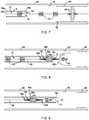
- FIG. 3Dillustrates an embodiment of a system 5d in which an expandable member 54d is slidable along a core wire 59d.
- the system 5dcan comprise a fixed blocking member 160d and a movable blocking member 60d.
- the fixed blocking member 160dcan define an outer profile or cross-section that is greater than an inner profile or cross-section of a lumen of the movable blocking member 60d, thus preventing the movable blocking member 60d from be able to pass or slide over fixed blocking member 160d.
- the movable blocking member 60dcan be disposed axially between the proximal and distal ends 58ad, 58bd of the expandable member 54d.
- the movable blocking member 60dcan be configured to define an outer profile or cross-section that is greater than the inner profile of the lumens of the proximal and distal ends 58ad, 58bd of the expandable member 54d.
- the lumen of the proximal end 58ad of the expandable member 54dcan define a profile or cross-section that is greater than an outer profile or cross-section of the fixed blocking member 160d.
- the proximal end 58adcan traverse or axially pass or slide over the fixed blocking member 160d, the proximal movement of the expandable member 54d can be limited upon contact between the fixed blocking member 160d, the movable blocking member 60d, and the distal end 58bd of the expandable member 54d.
- distal movement of the expandable member 54dcan be limited upon contact between the distal end 58bd of the expandable member 54d and the distal tip portion 7d.
- FIG. 3Eillustrates an embodiment of another system 5e in which an expandable member 54e is slidable along a core wire 59e.
- the system 5ecan comprise a pair of fixed blocking members 160e, 160e' and a movable blocking member 60e.
- the movable blocking member 60eis disposed axially between the proximal and distal ends 58ae, 58be of the expandable member 54e.
- the fixed blocking members 160e, 160e'can define outer profiles or cross-sections that are greater than an inner profile or cross-section of a lumen of the movable blocking member 60e, thus preventing the movable blocking member 60e from be able to pass or slide over fixed blocking members 160e, 160e'.
- the movable blocking member 60ecan define an outer profile or cross-section that is greater than the inner cross section of the lumens of the proximal and distal ends 58ae, 58be of the expandable member 54e. Further, the lumen of the proximal end 58ae of the expandable member 54e can define a profile or cross-section that is greater than an outer profile or cross-section of the fixed blocking member 160e, and the lumen of the distal end 58be of the expandable member 54e can define a profile or cross-section that is greater than an outer profile or cross-section of the fixed blocking member 160e'.
- the proximal end 58aecan traverse or axially pass or slide over the fixed blocking member 160e, and the distal end 58be can traverse or axially pass or slide over the fixed blocking member 160e'.
- the proximal movement of the expandable member 54ecan be limited upon contact between the fixed blocking member 160e, the movable blocking member 60d, and the distal end 58bd of the expandable member 54d.
- the distal movement of the expandable member 54ecan be limited upon contact between the fixed blocking member 160e', the movable blocking member 60e, and the proximal end 58ae of the expandable member 54e.
- FIG. 3Fillustrates yet another embodiment of a system 5f in which expandable member 54f is slidable along the core wire 59f.
- the system 5fcan comprise a pair of movable blocking members 60f, 60f' and a single fixed blocking member 160f interposed between the movable blocking members 60f, 60f'.
- the fixed blocking member 160fcan define an outer profile or cross-section that is greater than an inner profile or cross-section of a lumen of the movable blocking members 60f, 60f', thus preventing the movable blocking members 60f, 60f' from be able to pass or slide over fixed blocking member 160f.
- the movable blocking members 60f, 60f'can define outer cross sections that are greater than the inner profiles of the lumens of the proximal and distal ends 58af, 58bf of the expandable member 54f.
- proximal movement of the expandable member 54fcan be limited upon contact between the distal end 58bf of the expandable member 54f, the movable locking structure 60f', and the fixed blocking structure 160f.
- distal movement of the expandable member 54fcan be limited upon contact between the proximal end 58af of the expandable member 54f, the movable locking structure 60f, and the fixed blocking structure 160f.
- the expandable membercan be configured such that the size of the lumens of the proximal and distal ends can be configured to allow passage of some fixed blocking members while preventing the passage of other fixed blocking members.
- a proximal fixed blocking membercan be sized larger than a lumen of a proximal end of the expandable member, such that the proximal fixed blocking member does not permit the expandable member to pass any further proximally once the proximal fixed blocking member contacts the proximal end of the expandable member.
- the size of the lumen of the proximal end of the expandable membercan also be smaller than one or more distal fixed blocking members disposed along the core wire, similarly preventing the proximal end of the expandable member from advancing any further distally once the proximal end of the expandable member contacts the given distal fixed blocking member.
- the distal end of the expandable membercan comprise a lumen that is larger than a distal fixed blocking member, such that the distal end of the expandable member can pass over the distal fixed blocking member, allowing the distal end of the expandable member to be generally unconstrained relative to one or more distal fixed blocking members.
- FIG. 4illustrates an embodiment of a configuration comprising an expandable member 54k, a core wire 59k, and one or more fixed blocking members 160k, 160k'.
- the expandable member 54kcan comprise a proximal end 58ak and a distal end 58bk.
- the proximal and distal ends 58ak, 58bkcan each define lumens through which the core wire 59k can be slidably placed.
- the expandable member 54kin some embodiments, can slide relative to the core wire 59k.
- the length of travel of the expandable member 54kcan be limited by the distance between the fixed blocking members 160k, 160k'. Further, the proximal and distal ends 58ak, 58bk of the expandable member 54k can move relative to each other based on the expansion of the expandable member 54k.
- the lumen of the distal end 58bkcan define a diameter that is greater than a diameter of the fixed blocking member 160k'.
- the outer profile or shape of the fixed blocking member 160k' and the lumen of the distal end 58bkcan comprise shapes other than circular.
- the lumen of the distal end 58bkcan be sized to allow the fixed blocking member 160k' to pass therethrough.
- the lumen of the proximal end 58akcan be sized to prevent passage of the fixed blocking members 160k, 160k' therethrough.
- the outside diameter of the fixed blocking members 160k, 160k'can be greater than the inside diameter of the lumen of the proximal end 58ak.
- the inside diameter of the distal end 58bkcan be greater than the outside diameter of the fixed blocking member 160k'.
- the proximal end 58ak of the expandable member 54kcan be pushed distally by the fixed blocking member 160k or pulled proximally by the fixed blocking member 160k' while the distal end 58bk will not constrain or be constrained by the fixed blocking member 160k'.
- the blocking membercan be configured to engage with the expandable member to allow the clinician to distally push the expandable member while engaging a distal end of the expandable member and/or to withdraw the expandable member while engaging a proximal end of the expandable member.
- the expandable membercan be moved without axially compressing the expandable member, which could cause the expandable member to invert or become jammed inside of the stent lumen.
- the presence of one or more blocking memberscan allow the clinician to push and/or pull the core wire until the one or more blocking members interacts with an end of the expandable member, whereupon further pushing or pulling of the core wire allows the clinician to impart a pushing or pulling force on the expandable member.
- the systemcan be configured such that stent foreshortening during stent expansion does not force the expandable member distally beyond the stent distal end.
- stent distal endis initially "landed" and contacts the vessel wall, subsequently expanded sections of the stent will axially foreshorten, thus causing the overall stent to axially foreshorten and draw or advance the unexpanded stent proximal end in a distal direction. While the unexpanded stent proximal end advances distally, the core wire will tend to also advance distally relative to the stent distal end.
- the systemin order to prevent the expandable member from being forced distally beyond the stent distal end, can be configured such that blocking members positioned along the core wire do not engage with the stent proximal end or the stent distal end to push the expandable member distally beyond the stent distal end during expansion of the stent.
- the expandable member 54kcan move axially along the core wire 59k, constrained by the interaction between the proximal end 58ak and the fixed blocking members 160k, 160k', but not constrained by the interaction between the distal end 58bk and the fixed blocking members 160k, 160k'.
- the fixed blocking memberscan be placed along the core wire 59k such that the expandable member 54k is not pushed out of the stent distal end as the core wire 59k advances distally during stent expansion.
- the (proximal) fixed blocking member 160kcan be positioned along the core wire 59k spaced sufficiently apart from the expandable member proximal end such that the fixed blocking member 160k will not contact or will only insubstantially contact the proximal end 58ak such that any contact does not urge the expandable member 54k out of the stent distal end.
- the fixed blocking member 160kcan be proximally spaced apart from the proximal end 58ak of the expandable member 54k by a first distance.
- the first distancecan be about equal to or greater than the distance that the core wire will advance relative to the stent distal end during stent expansion or as the stent delivery system moves to the deployed state in which the stent is fully expanded and released from the stent delivery system.
- the first distancecan be between about 2 mm and about 60 mm. In some embodiments, the first distance can be between about 5 mm and about 40 mm. Further, in some embodiments, the first distance can be between about 10 mm and about 30 mm.
- the expandable member 54kcan be positioned within the stent lumen and the fixed blocking member 160k can be located proximal to or outside of the stent proximal end when the stent is in the collapsed position.
- the fixed blocking member 160kcan be spaced apart from the stent proximal end such that when the stent expands and the core wire 59k and the fixed blocking member 160k advance, the fixed blocking member 160k will not force the expandable member 54k distally beyond the stent distal end.
- the distal fixed blocking membercan be spaced from the stent distal end at a second distance. Similar to the first distance mentioned above, the second distance can be between about 2 mm and about 60 mm. In some embodiments, the second distance can be between about 5 mm and about 40 mm. Further, in some embodiments, the second distance can be between about 10 mm and about 30 mm.
- the distal fixed blocking membercan be located proximal to the stent proximal end when the stent is in the collapsed position and can be configured such that it passes through and does not engage the stent proximal end. Furthermore, in some embodiments, the distal fixed blocking member can be located distal to the stent proximal end when the stent is in the collapsed position.
- FIGS. 3B-GOther embodiments disclosed herein that incorporate one or more (fixed and/or movable) blocking members, such as the embodiments illustrated in FIGS. 3B-G , can also be configured such that stent expansion does not force the expandable member distally beyond the stent distal end.
- a fixed blocking member(s)can be spaced at an offset that allows the fixed blocking member to be advanced distally without pushing the expandable member out of the stent distal end, as discussed similarly above with respect to the first and second distances.
- the blocking member(s)can be configured to engage with the expandable member to allow the clinician to distally push the expandable member while engaging a distal end of the expandable member and/or to withdraw the expandable member while engaging a proximal end of the expandable member.
- the embodiment illustrated in Figure 3Eillustrates a system in which the movable blocking member 60e is disposed between the proximal and distal ends 58ae, 58be of the expandable member 54e.
- the movable blocking member 60eis sized to have an outer cross-sectional profile that is greater than the inner cross-sectional profile of the proximal and distal ends 58ae, 58be, which thereby constrains movement of the movable blocking member 60e.
- the movable blocking member 60eengages with either of the fixed blocking members 160e, the movable blocking member 60e will also engage with the expandable member 54e upon further movement of the core wire 59e in a given direction.
- the fixed blocking member 58becan initially contact the movable blocking member 60e and, upon further proximal movement of the core wire 59e, the movable blocking member 60e will contact the proximal end 58ae of the expandable member 54e. Additional proximal movement of the core wire 59e will thus withdraw the expandable member 54e in a proximal direction. As this occurs, the proximal end 58ae of the expandable member 54e may tend to (at least initially) be moved proximally away from the distal end 58be, thus potentially and initially somewhat elongating the expandable member 54e. However, the expandable member 54e will not tend to be jammed, inverted, or otherwise deflected from an expanded shape that can be optimal for facilitating complete stent expansion.
- the fixed blocking member 58aecan initially contact the movable blocking member 60e and, upon further distal movement of the core wire 59e, the movable blocking member 60e will contact the distal end 58be of the expandable member 54e. Additional distal movement of the core wire 59e will thus "push" the expandable member 54e in a proximal direction. As this occurs, the distal end 58be of the expandable member 54e may tend to (at least initially) be moved distally away from the proximal end 58ae, thus potentially and initially somewhat elongating the expandable member 54e. However, the expandable member 54e will not tend to be jammed, inverted, or otherwise deflected from an expanded shape that can be optimal for facilitating complete stent expansion.
- a fixed blocking membercan be coupled to a core wire and can be sized such that an outer cross-sectional profile of the fixed blocking member is greater than an inner cross-sectional profile of the lumens of the proximal and distal ends of the expandable member.
- an embodiment having only a single blocking membercan be provided that allows the expandable member to be pushed distally while engaging the expandable member distal end and withdrawn proximally while engaging the expandable member proximal end.
- the blocking member(s)can engage with a distal end of the expandable member to push the expandable member distally and/or can engage with a proximal end of the expandable member to withdraw the expandable member proximally.
- the expandable membercan be moved proximally or distally without axially compressing the proximal and distal ends of the expandable member, which could cause the expandable member to invert or become jammed inside of the stent lumen.
- one or more of the fixed blocking memberscan be formed along the core wire as a protrusion or structure of the core wire itself.
- one or more of the fixed blocking structurescan also be a distinct structure that is formed separately of and coupled to the core wire in a manner that prevents at least axial movement of the fixed blocking structure along the core wire.
- the term "fixed” in some embodimentscan refer at least to axial fixation along the core wire, while optionally permitting rotational movement of the fixed blocking structure relative to the core wire.
- the fixed blocking member and the lumencan comprise one or more surface features, such as threads, protrusions, or recesses configured such that the lumen and the fixed blocking member can interact as the lumen passes over the fixed blocking member.
- the fixed blocking member and the lumendo not pass over each other, the fixed blocking member and/or the lumen can comprise structures or other features that can interact with each other to fix the rotational position of the expandable member relative to the core wire.
- the above-noted examplesprovide possible configurations that can limit the proximal and/or distal movement of the expandable member relative to the core wire.
- Embodimentscan be provided in which the movable blocking structures are omitted and the inner profiles of the lumens of the proximal and distal ends of the expandable member are configured to correspond with an outer profile or cross-section of the fixed blocking member(s).
- some embodimentscan comprise at least one floating or movable blocking structure that can interact with a fixed blocking structure and one or both of the ends of the expandable member to limit or control axial and/or rotational movement of the expandable member.
- the inner and/or outer "cross-section" of the lumens and members discussed hereincan define any of a variety of geometric shapes or profiles.
- profilescan be provided that have one or more longitudinally extending slits or grooves that can provide a keyed structure so as to limit rotational movement of the expandable member relative to the core wire, but to allow axial movement of the expandable member relative to the core wire.
- profilescan be provided that provide a proximal and/or distal axial travel limit while allowing rotation of the expandable member relative to the core wire.
- the expandable member 54can include between 3 and 5 struts, between 5 and 10 struts, between 10 and 15 struts, between 15 and 20 struts, or 20 or more struts.
- the expandable member 54is characterized or otherwise depicted as an expanded tube or "onion-shaped" structure, it can equally conform to other shapes and/or configurations in order to fit particular applications. Other such shapes and/or configurations can include an ellipsoid of revolution, a prolate spheroid, etc.
- the core assembly 57can further include a distal stent cover 71 configured to act as a bearing or reduce friction between the stent 66 (e.g., the distal portion or distal end 67 thereof) and the inner surface 17 of the catheter 8. As shown in the embodiment in FIG. 2 , the core assembly 57 can be configured such that the distal stent cover 71 extends adjacent to or at least partially axially over the expandable member 54.
- the expandable membercan be positioned along the distal end of the core assembly 57.
- the expandable member 54is shown in FIG. 2 as being axially positioned adjacent to the distal end 67 of the stent 66.
- the expandable member 54can be positioned inside of the distal end 67 of the stent 66 and inside of the proximal portion of the distal stent cover 71.
- the expandable member 54can extend beyond the distal end 67 of the stent 66 and into a space defined by the proximally extending proximal portion of the distal stent cover 71.
- the expandable membercan be positioned along the proximal end of the core assembly 57.
- the expandable membercan also be positioned between the proximal and distal ends of the core assembly.
- the expandable membercan be positioned between the proximal and distal ends 68, 67 of the stent 66.
- eachcan be positioned at or between the proximal and distal ends of the core assembly.
- the distal stent cover 71can be made of a lubricious and/or hydrophilic material.
- the distal stent cover 71can be made of polytetrafluoroethylene, better known as TEFLON®, but can be made from other lubricious materials known by those skilled in the art, without departing from the scope of the disclosure.
- the distal stent covercan include a proximal portion 71a and a distal portion 71b.
- the distal portion 71b of the distal stent cover 71can be coupled to the tip coil 61 using, for example, a shrink tube 73 configured to shrink and capture a distal end of the distal stent cover 71 against the tip coil 61.
- the distal portion 71b of the distal stent cover 71is coupled to the tip coil 61 via other devices or attachment means, including, but not limited to mechanical fasteners, welding techniques, adhesives, heat bonding, combinations thereof, or the like.
- the distal stent cover 71i.e., the distal portion 71b
- the distal portion 71bis coupled or otherwise attached directly to the distal portion 53b of the core wire 59 itself using one or more of the devices or attachment means discussed herein.
- the distal stent cover 71can be manufactured or otherwise cut from a tube of the material selected for the distal stent cover 71.
- the proximal portion 71acan be formed as strips cut from the tube, and the distal portion 71b can be an uncut length of the tube. Accordingly, the tubular distal portion 71b and the proximally extending strips of the proximal portion 71a can form a single, integral device or structure.
- the distal stent cover 71can be a generally cylindrical or tubular structure formed by one or more strips or flaps of material coupled to the distal tip portion. For example, the distal stent cover 71 can be attached to the tip coil 61.
- the tubular distal portion 71bcan be shrunk onto or otherwise coupled to the tip coil 61 using mechanical fasteners, welding techniques, adhesives, heat bonding, combinations thereof, or the like, and the shrink tube 73 can be used, as described above. In yet other embodiments, the shrink tube 73 alone can be coupled to the tubular distal portion 71b to the tip coil 61.
- the distal stent cover 71can comprise a tube wherein the proximal portion 71a includes two or more semi-cylindrical or partially cylindrical strips or tube portions separated by a corresponding number of generally parallel, longitudinally oriented cuts or separations formed or otherwise defined in the sidewall of the tube. Therefore, when in the pre-deployment state, as shown in FIGS. 2-3 , the proximal portion 71a can generally have the shape of a longitudinally split or longitudinally slotted tube interposed between the outer surface 40b of the stent 66 and the inner surface 17 of the catheter 8.
- the strips of the proximal portion 71acan collectively span substantially the entire circumference of the outer surface 40b of the stent 66 (e.g., where the cuts between the strips are splits of substantially zero width), or somewhat less than the entire circumference (e.g., where the cuts between the strips are slots having significant width).
- the strips of the proximal portion 71acan be of substantially uniform size; e.g., two strips spanning approximately 180 degrees each, three strips of approximately 120 degrees each, four strips of approximately 90 degrees each, etc. Alternatively, the strips can differ in angular sizing, without departing from the scope of the disclosure. In some embodiments, only two strips or tube portions are employed in the proximal portion 71a.
- the use of two stripsfacilitates fold-over or everting of the distal stent cover 71, as discussed in more detail below, while minimizing the number of free or uncontained strips in the blood vessel lumen and any potential for injuring the vessel by virtue of contact between a strip and the vessel wall.
- the proximal portion 71a of the distal stent cover 71can be inverted or otherwise folded within itself, thereby creating a folded region 74 interposed between the outer surface 40b of the stent 66 and the inner surface 17 of the catheter 8.
- the folded region 74defines an outer layer 74a and an inner layer 74b, where the outer layer 74a is adjacent the inner surface 17 of the catheter 8 and the inner layer 74b is adjacent the outer surface 40b of the stent 66.
- the distal stent cover 71can be configured to fold over itself, in a manner opposite to that shown in FIG.
- proximal portion 71ais not folded, inverted, or everted at all, when in the pre-deployment configuration.
- the distal stent cover 71In operation, the distal stent cover 71, and in particular the folded region 74, generally covers and protects the distal end 67 of the stent 66 as the stent 66 is axially translated within the catheter 8.
- the distal stent cover 71can serve as a bearing or buffer layer that, for example, prevents the filament ends 99 of the stent 66 from contacting the inner surface 17 of the catheter 8, which could damage the stent 66 and/or catheter 8, or otherwise compromise the structural integrity of the stent 66.
- ends of the folded region 74can be inverted within the distal stent cover 71, such that the end of the distal stent cover 71 forms the inner layer/surface between the outer surface of the stent 66 and the distal stent cover 71.
- Thiscan permit distal advancement of the core wire assembly through the catheter 8, while engaging the inner surface of the catheter 8, without unfurling. Since the distal stent cover 71 can be made of a lubricious material, the distal stent cover 71 can exhibit a low coefficient of friction that allows the distal end 67 of the stent 66 to translate or slide within the catheter 8 with relative ease.
- the distal stent cover 71can have a coefficient of friction of between about 0.02 and about 0.2. In some embodiments, the distal stent cover 71 can have a coefficient of friction of about 0.04. Accordingly, the distal stent cover 71 may be configured to provide a lubricious interface between the outer surface 40b of the stent 66 and the inner surface 17 of the catheter 8.
- operation of a stent delivery system 5is illustrated in accordance with aspects of some embodiments. Operation of some embodiments can be performed such that the catheter 8 is percutaneously introduced into a blood vessel 69 and advanced to a treatment site in the blood vessel 69, such as the site of an aneurysm (not shown).
- the catheter 8is guided to the treatment site using fluoroscopic imaging, in which one or more radiopaque markers (not shown) located on the distal portion 18b of the catheter 8 indicate a position of the catheter 8 in a fluoroscopic image.
- the catheter 8can also be guided using other imaging techniques including, but not limited to, ultrasound and magnetic resonance imaging.
- the expandable membercan comprise one or more radiopaque materials or portions to facilitate fluoroscopic imaging of the stent delivery system.
- the expandable membercan be fabricated from a radiopaque material or comprise one or more markers located on the proximal or distal ends thereof.
- FIGS. 2-3depict the stent delivery system 5 with the stent 66, expandable member 54, and distal stent cover 71 in a pre-deployment configuration. While in this configuration, the stent 66, expandable member 54, and distal stent cover 71 can be advanced distally within the catheter 8 from a starting location (e.g., in a proximal portion of the catheter 8, which can be outside of the body of the patient) to a location within the distal portion of the catheter 8, at or near the distal end 18b thereof.
- a starting locatione.g., in a proximal portion of the catheter 8, which can be outside of the body of the patient
- This advancementcan be achieved by applying a distally directed force to the core wire 59, which force can be transmitted to the stent 66 via the bumpers(s) 62.
- the proximal portion 71a of the distal stent cover 71remains interposed between the outer surface 40b and/or distal end 67 of the stent 66 and the inner surface 17 of the catheter 8.
- the distal stent cover 71can prevent the distal end 67 of the advancing stent 66 (e.g., the filament ends 99 thereof) from damaging, abrading, or gouging the catheter 8, and from thereby impeding progress of the stent 66 along the catheter 8. This can, in turn, prevent damage to the stent 66 such as by longitudinal compression resulting from high friction generated between the distal end 67 and the catheter 8 while distally directed force is applied to the proximal portions of the stent 66.
- the distal end 67 of the advancing stent 66e.g., the filament ends 99 thereof
- Thiscan, in turn, prevent damage to the stent 66 such as by longitudinal compression resulting from high friction generated between the distal end 67 and the catheter 8 while distally directed force is applied to the proximal portions of the stent 66.
- the distal end 67 of the stent 66can be advanced beyond the distal portion 18b of the catheter 8 while the proximal end 68 of the stent 66 remains compressed within the catheter 8. As the distal end 67 of the stent 66 exits the distal opening 19, it can automatically expand, be expanded manually, or self-expand to an expanded configuration. In its expanded configuration, the outer surface 40b of the stent 66 can be "landed" or extend to and preferably lie mostly or completely adjacent to the inner surface 55 of the blood vessel 69. Thereafter, the stent 66 can be fully deployed at the site or resheathed and repositioned, if necessary.
- the stent 66can contract axially as it expands radially within the blood vessel.
- the axial foreshortening of both the stent 66 and the expandable member 54, and their respective radial expansionscan cause the strips or tube portions of the proximal portion 71a ( FIG. 3A ) of the distal stent cover 71 to separate and move radially outward, disengaging from contact with the stent 66.
- the distal stent cover 71moves and/or disengages from the stent, it unfurls or otherwise unravels from its folded configuration ( FIG. 3A ).
- distal stent cover 71may no longer cover the distal end 67 of the stent 66. Instead, the distal stent cover 71 may be left coupled to the tip coil 61 and its free ends may be generally unconstrained within the blood vessel 69.
- the distal stent cover 71can be configured to entirely invert or fold back over itself as the wire 59 is drawn proximally.
- the distal stent cover 71can be flexible and be able to be proximally withdrawn into the catheter to allow the core assembly (including the stent) to be resheathed or removed through the catheter.
- thiscan prove beneficial when the core assembly is withdrawn into the catheter after the stent has been deployed, which can allow for another core assembly (with an additional stent) to be introduced through the catheter to permit "telescoping" or placement of multiple stents without having to remove the catheter.
- the flexibility of the distal stent cover 71can also prove beneficial when the initial deployment site of the stent 66 is incorrect or otherwise has to be relocated to properly cover the treatment site of interest. Accordingly, in some embodiments, the stent 66 can be partially deployed, resheathed, and relocated multiple times as needed in order to ensure that the stent 66 is properly deployed in the correct location for best use.
- the catheter 8can be retracted further proximally relative to the stent 66.
- the released portions of the stent 66can be expanded (automatically or manually) to contact the inner surface 55 of the blood vessel 69.
- the stent 66can be retracted or otherwise resheathed back into the catheter 8.
- the one or more stent bumpers 62which can still be in contact with, urged, or biased against the inner surface 40a of the stent 66, can grip the stent 66 to facilitate moving it proximally and back into its compressed configuration within the catheter 8.
- the core wire 59can be pulled proximally while the catheter 8 remains stationary. As the core wire 59 moves proximally, if the core assembly 57 has any stent bumpers 62, they can be reintroduced into the catheter 8. Once the expandable member 54 reaches the distal opening 19, the struts 54a-c contact the distal portion 18b of the catheter 8 and are thereby forced back into their compressed configurations. As discussed above, the proximal and/or distal ends 58a, 58b can be freely axially movable along the core wire 59.
- the proximal and/or distal ends 58a, 58bcan translate proximally and/or distally along the core wire 59 to facilitate compression or contraction of the expandable member 54.
- the contact between the expandable member 54 and the catheter 8can force the distal end 58b of the expandable member 54 to slide distally along the core wire 59 and thereby axially elongate and collapse or compact the expandable member 54 for reinsertion in the catheter 8.
- the expandable member 54can facilitate the initial expansion and/or the subsequent or final expansion of the stent.
- the expandable membercan facilitate the initial expansion when the distal end of the stent is "landed" at the desired location. Further, after the stent is completely released from the core assembly, the expandable member can be used to urge partially expanded portions of the stent towards a fully expanded configuration by engaging the inner surface of the stent.
- the expandable membercan move from the collapsed position toward the expanded position.
- the distal end and the proximal end of the expandable membercan converge toward each other which allows the struts to expand radially.
- some embodiments of the expandable membercan comprise resilient struts or configuration that causes the expandable member to move to a radially expanded shape when outside of the catheter 8.
- one or both of the proximal and distal ends 58a, 58b of the members 54a-c of the expanding member 54can slide or otherwise translate along the core wire 59 to facilitate radial expansion of the expanding member 54.
- the distal end 58bcan contract proximally (i.e., converge axially toward the fixed proximal end 58a). These movements can cause the expandable member 54 to be axially contracted or foreshortened and radially expanded.
- the expandable member 54can cause at least a portion of the stent 66 to expand.
- the expandable member 54can cause at least a portion of the stent 66 to expand by expanding and engaging the inner surface of the stent 66.
- the expandable membercan facilitate expansion of the distal end of the stent to "land" the stent in the vessel.
- the expandable membercan be used to help achieve consistent results of the system and provide full initial expansion of the stent within the blood vessel.
- the expandable member 54can expand automatically, be expanded manually, or self-expand to its natural, expanded configuration.
- the strutscan be configured such that spring forces in each of the struts 54a-c can tend to facilitate to the expansion of the distal end 67 of the stent 66. Accordingly, the expandable member 54 can facilitate a more complete initial expansion of the distal end 67 of the stent 66 into apposition with the vessel, thereby assisting in the initial anchoring of the distal end 67 of the stent 66.
- the stent 66results in better wall apposition, such that an increased amount of friction is generated against the inner surface 55 of the blood vessel 69 by the stent 66.
- increasing the friction force between the blood vessel 69 and the stent 66can allow the user to strategically expand the remaining portions of the stent 66.
- other portions of the stente.g., central portions, proximal portion, etc.
- more than one expandable membercan be used in some embodiments, which can be employed to facilitate initial and/or subsequent or final expansion of the stent.
- the expandable membercan facilitate not only initial expansion upon deployment, but can also be passed along the lumen of the deployed stent to force open portions of the stent that may not have deployed fully. Thus, subsequent to the initial deployment, unsheathing, or release of the stent from the core wire, the expandable member can be passed axially along the lumen of the stent to tend to urge open any portions of the stent that did not expand into apposition with the walls of the vessel.
- the expandable member 54can be used to ensure that every portion of the stent 66 is fully engaged with the inner surface 55 of the blood vessel 69.
- the stent 66can provide structural support to the vessel wall 55 to strengthen the blood vessel 69 and prevent or reduce the likelihood of reclosure.
- the expandable member 54can be translated axially back and forth within the deployed stent 66, continuously urging or biasing the inner surface 40a of the stent 66, such as in the use of a mandrel-type device.
- any sagging or unapposed portions of the stent 66can be pressed or forced into proper engagement with the blood vessel 69 as the expandable member 54 translates along the lumen of the stent 66.
- the catheter 8 and core assembly 57can be withdrawn from the blood vessel 69 or otherwise retracted out of the vasculature of the patient.
- the catheter 8 and the core assembly 57can be removed separately from the blood vessel 69.
- the core assembly 57can be resheathed back into the catheter 8 and removed with the catheter 8.
- the core assembly 57can be easily withdrawn through the catheter 8 by itself (with the catheter 8 remaining in place) after stent deployment to facilitate "telescoping" or to reduce overall rigidity of the catheter assembly, such that the catheter can be more flexible when being withdrawn from the vessel.
- vesselscan include arteries or veins.
- the vesselscan be suprathoracic vessels (e.g., vessels in the neck or above), intrathoracic vessels (e.g., vessels in the thorax), subthoracic vessels (e.g., vessels in the abdominal area or below), lateral thoracic vessels (e.g., vessels to the sides of the thorax such as vessels in the shoulder area and beyond), or other types of vessels and/or branches thereof.
- the stent delivery systems disclosed hereincan be deployed within superthoracic vessels.
- the suprathoracic vesselscan comprise at least one of intracranial vessels, cerebral arteries, and/or any branches thereof.
- the suprathoracic vesselscan comprise at least one of a common carotid artery, an internal carotid artery, an external carotid artery, a middle meningeal artery, superficial temporal arteries, an occipital artery, a lacrimal (ophthalmic) artery, an accessory meningeal artery, an anterior ethmoidal artery, a posterior ethmoidal artery, a maxillary artery, a posterior auricular artery, an ascending pharyngeal artery, a vertebral artery, a left middle meningeal artery, a posterior cerebral artery, a superior cerebellar artery, a basilar artery, a left internal acoustic (labyrinthine) artery, an
- the suprathoracic vesselscan also comprise at least one of a medial orbitofrontal artery, a recurrent artery (of Heubner), medial and lateral lenticulostriate arteries, a lateral orbitofrontal artery, an ascending frontal (candelabra) artery, an anterior choroidal artery, pontine arteries, an internal acoustic (labyrinthine) artery, an anterior spinal artery, a posterior spinal artery, a posterior medial choroidal artery, a posterior lateral choroidal artery, and/or branches thereof.
- a medial orbitofrontal arterya recurrent artery (of Heubner), medial and lateral lenticulostriate arteries, a lateral orbitofrontal artery, an ascending frontal (candelabra) artery, an anterior choroidal artery, pontine arteries, an internal acoustic (labyrinthine) artery, an anterior spinal artery,
- the suprathoracic vesselscan also comprise at least one of perforating arteries, a hypothalamic artery, lenticulostriate arteries, a superior hypophyseal artery, an inferior hypophyseal artery, an anterior thalamostriate artery, a posterior thalamostriate artery, and/or branches thereof.
- the suprathoracic vesselscan also comprise at least one of a precentral (pre-Rolandic) and central (Rolandic) arteries, anterior and posterior parietal arteries, an angular artery, temporal arteries (anterior, middle and posterior), a paracentral artery, a pericallosal artery, a callosomarginal artery, a frontopolar artery, a precuneal artery, a parietooccipital artery, a calcarine artery, an inferior vermian artery, and/or branches thereof.
- pre-Rolandicprecentral
- central (Rolandic) arteriesanterior and posterior parietal arteries
- an angular arteryan angular artery
- temporal arteriesanterior, middle and posterior
- a paracentral arterya pericallosal artery
- a callosomarginal arterya frontopolar artery
- a precuneal arterya parietoo
- the suprathoracic vesselscan also comprise at least one of diploic veins, an emissary vein, a cerebral vein, a middle meningeal vein, superficial temporal veins, a frontal diploic vein, an anterior temporal diploic vein, a parietal emissary vein, a posterior temporal diploic vein, an occipital emissary vein, an occipital diploic vein, a mastoid emissary vein, a superior cerebral vein, efferent hypophyseal veins, infundibulum (pituitary stalk) and long hypophyseal portal veins, and/or branches thereof.
- the intrathoracic vesselscan comprise the aorta or branches thereof.
- the intrathoracic vesselscan comprise at least one of an ascending aorta, a descending aorta, an arch of the aorta, and/or branches thereof.
- the descending aortacan comprise at least one of a thoracic aorta, an abdominal aorta, and/or any branches thereof.
- the intrathoracic vesselscan also comprise at least one of a subclavian artery, an internal thoracic artery, a pericardiacophrenic artery, a right pulmonary artery, a right coronary artery, a brachiocephalic trunk, a pulmonary trunk, a left pulmonary artery, an anterior interventricular artery, and/or branches thereof.
- the intrathoracic vesselscan also comprise at least one of an inferior thyroid artery, a thyrocervical trunk, a vertebral artery, a right bronchial artery, a superior left bronchial artery, an inferior left bronchial artery, aortic esophageal arteries, and/or branches thereof.
- the intrathoracic vesselscan also comprise at least one of a right internal jugular vein, a right brachiocephalic vein, a subclavian vein, an internal thoracic vein, a pericardiacophrenic vein, a superior vena cava, a right superior pulmonary vein, a left brachiocephalic vein, a left internal jugular vein, a left superior pulmonary vein, an inferior thyroid vein, an external jugular vein, a vertebral vein, a right highest intercostal vein, a 6th right intercostal vein, an azygos vein, an inferior vena cava, a left highest intercostal vein, an accessory hemiazygos vein, a hemiazygos vein, and/or branches thereof.
- the subthoracic vesselscan comprise at least one of renal arteries, inferior phrenic arteries, a celiac trunk with common hepatic, left gastric and splenic arteries, superior suprarenal arteries, a middle suprarenal artery, an inferior suprarenal artery, a right renal artery, a subcostal artery, 1st to 4th right lumbar arteries, common iliac arteries, an iliolumbar artery, an internal iliac artery, lateral sacral arteries, an external iliac artery, a testicular (ovarian) artery, an ascending branch of deep circumclex iliac artery, a superficial circumflex iliac artery, an inferior epigastric artery, a superficial epigastric artery, a femoral artery, a ductus deferens and testicular artery, a superficial external pudendal artery, a deep external pudendal artery, and/or branches thereof.
- the subthoracic vesselscan also comprise at least one of a superior mesenteric artery, a left renal artery, an abdominal aorta, an inferior mesenteric artery, colic arteries, sigmoid arteries, a superior rectal artery, 5th lumbar arteries, a middle sacral artery, a superior gluteal artery, umbilical and superior vesical arteries, an obturator artery, an inferior vesical and artery to ductus deferens, a middle rectal artery, an internal pudendal artery, an inferior gluteal artery, a cremasteric, pubic (obturator anastomotic) branches of inferior epigastric artery, a left colic artery, rectal arteries, and/or branches thereof.
- a superior mesenteric arterya left renal artery, an abdominal aorta
- an inferior mesenteric arterycolic arteries
- sigmoid arteriesa superior
- the lateral thoracic vesselscan comprise at least one of humeral arteries, a transverse cervical artery, a suprascapular artery, a dorsal scapular artery, and/or branches thereof.
- the lateral thoracic vesselscan also comprise at least one of an anterior circumflex humeral artery, a posterior circumflex humeral artery, a subscapular artery, a circumflex scapular artery, a brachial artery, a thoracodorsal artery, a lateral thoracic artery, an inferior thyroid artery, a thyrocervical trunk, a subclavian artery, a superior thoracic artery, a thoracoacromial artery, and/or branches thereof.
- a cathetersuch as that described in U.S. Patent Application No. 12/731,110 , which was filed on March 24, 2010, can be used to deliver a stent delivery system.
- the delivery systemcan include an expandable occluding device (e.g., stent) configured to be placed across an aneurysm that is delivered through the distal portion of the catheter, out a distal tip, and into the vasculature adjacent an aneurysm in, for example, the middle cerebral artery.
- a proximal portion of the cathetercan remain partially or entirely within a guiding catheter during delivery, and an intermediate portion, taper portion, and distal portion of the catheter can extend distally of the guiding catheter.
- the occluding devicecan be released at the target location and can be used to occlude blood flow into the aneurysm.
- the cathetercan be used to reach target locations (e.g., aneurysms) located elsewhere in the body as well, include but not limited to other arteries, branches, and blood vessels such as those described above.
Landscapes
- Health & Medical Sciences (AREA)
- Engineering & Computer Science (AREA)
- Biomedical Technology (AREA)
- Cardiology (AREA)
- Oral & Maxillofacial Surgery (AREA)
- Transplantation (AREA)
- Heart & Thoracic Surgery (AREA)
- Vascular Medicine (AREA)
- Life Sciences & Earth Sciences (AREA)
- Animal Behavior & Ethology (AREA)
- General Health & Medical Sciences (AREA)
- Public Health (AREA)
- Veterinary Medicine (AREA)
- Media Introduction/Drainage Providing Device (AREA)
Description
- The present application generally relates to implantable devices for use within a patient's body and, more particularly, relates to systems for implanting devices, such as stents, in a patient's body and monitoring an occlusion.
- Lumens in the body can change in size, shape, and/or patency, and such changes can present complications or affect associated body functions. For example, the walls of the vasculature, particularly arterial walls, may develop pathological dilatation called an aneurysm. Aneurysms are observed as a ballooning-out of the wall of an artery. This is a result of the vessel wall being weakened by disease, injury or a congenital abnormality. Aneurysms have thin, weak walls and have a tendency to rupture and are often caused or made worse by high blood pressure. Aneurysms can be found in different parts of the body; the most common being abdominal aortic aneurysms (AAA) and the brain or cerebral aneurysms. The mere presence of an aneurysm is not always life-threatening, but they can have serious heath consequences such as a stroke if one should rupture in the brain. Additionally, a ruptured aneurysm can also result in death.
WO2012/068175 discloses endovascular prostheses and methods of deploying the same, which may be directed more specifically to stent grafts and methods of positioning and deploying such devices within the body of a patient.US2005/288763 discloses self-expanding stent delivery systems with stent bumpers.US2008/132989 discloses devices and methods for controlling expandable prostheses during deployment.DE102010050569 discloses a device for releasing a self-expandable medical functional element.US2010/249894 discloses a two-stage prosthetic heart valve system having a radially expandable based stent implanted within a native of valve annulus.US2007/233224 discloses an implantable medical endoprosthesis delivery system.US5158548 discloses a stent delivery system having an expandable stent in a contracted condition positioned on an expandable member, such as an inflatable balloon, disposed on the distal portion of an elongated catheter body.US2012/226343 discloses a stent delivery system comprising a self-expanding stent disposed over a frictional interfacing member and delivery member in a radially contracted configuration.- At least one aspect of the disclosure provides systems for implanting a device or devices (e.g., stent or stents) in the body. The device can easily conform to the shape of the tortuous vessels of the vasculature. The device can direct the blood flow within a vessel away from an aneurysm. Additionally, such a device can allow adequate blood flow to be provided to adjacent structures, such that those structures, whether they are branch vessels or oxygen demanding tissues, are not deprived of the necessary blood flow.
- In accordance with some embodiments, a stent delivery system is provided that comprises an elongate body, a stent, a core wire, and an expandable member. The elongate body comprises a distal portion, a proximal portion, and an inner surface extending from the distal portion to the proximal portion. The distal portion is configured to extend within a blood vessel of a patient. The stent is expandable from a compressed configuration to an expanded configuration. The stent has a proximal end, a distal end, an inner surface, and an outer surface. The inner and outer surfaces extend from the proximal end to the distal end. The core wire is extensible through the elongate body and the stent has a distal region or terminal portion. The expandable member is disposed along the core wire. The expandable member is configured to facilitate the expansion of at least a portion of the stent to the expanded configuration by expanding and engaging the inner surface of the stent.
- The expandable member comprises first and second ends that are rotatably and slidably movable relative to the core wire. The expandable member can be positioned proximally of the stent proximal end when the stent is in the compressed configuration. However, the expandable member can be positioned within a lumen of the stent when the stent is in the compressed configuration. The delivery system further comprises at least one blocking member disposed along the core wire. The blocking member is configured to limit the movement of the expandable member relative to the core wire. Further, the clinician can push or withdraw the core wire until the blocking member(s) contact(s) the expandable member, whereupon further pushing or withdrawing of the core wire allows the clinician to push or withdraw the expandable member.
- In accordance with some embodiments, the blocking member(s) can engage with a distal end of the expandable member to push the expandable member distally. The blocking member(s) can also engage with a proximal end of the expandable member to withdraw the expandable member proximally. For example, the blocking member(s) can be disposed along the core wire between expandable member first and second ends, and the blocking member(s) can have an outer cross-sectional profile that is greater than an inner cross-sectional profile of the lumens of the expandable member first and second ends. Further, in such embodiments, the blocking member(s) can be a fixed blocking member. In some embodiments, the fixed blocking member can be fixed to the core wire.
- Thus, in some embodiments, the expandable member can be moved proximally or distally without axially compressing the proximal and distal ends of the expandable member, which could cause the expandable member to invert or become jammed inside of the stent lumen.
- The at least one blocking member comprises at least one fixed blocking member. The fixed blocking member can be fixed to the core wire. The fixed blocking member can define an outer profile or cross-section that is greater than an inner profile or cross-section of a lumen of the movable blocking member. Accordingly, one or more fixed blocking members can be positioned along the core wire and interact with one and/or both of the ends of the expandable member to limit the travel thereof.
- In some embodiments, the at least one blocking member can comprise at least one fixed blocking member and at least one movable blocking member. In such embodiments, the movable blocking member can define an outer profile or cross-section that is greater than an inner profile or cross-section of a lumen of an end of the expandable member. Further, the movable blocking member can have a lumen that defines an inner profile or cross-section section that is less than an outer profile or cross-section of a fixed blocking member disposed along the core wire. The movable blocking member can be disposed between an end of the expandable member and the fixed blocking member. Thus, the end of the expandable member can be blocked from sliding past the movable blocking member and the fixed blocking member.
- The expandable member can be configured to comprise a plurality of filaments extending from a first end to a second end thereof. Further, the expandable member can comprise a shape memory material. The expandable member can self-expand upon being unsheathed from a microcatheter, e.g., when radially unrestrained by the elongate body.
- The system can also optionally comprise a distal stent cover extending proximally from the distal region of the core wire and interposed between the outer surface of the stent and the inner surface of the elongate member. The distal stent cover can comprise a folded region having (a) an outer layer configured to be urged against the inner surface of the elongate member and (b) an inner layer configured to contact the outer surface of the stent. Further, the folded region can be an inverted section of the distal stent cover where the distal stent cover folds within itself. The distal stent cover can be coupled to the core wire. Further, the distal stent cover can be formed by one or more flaps of material. The distal stent cover can also comprise a lubricious material.
- The system can further comprise an atraumatic tip coil coupled to the distal region of the core wire. For example, the distal stent cover can be coupled to the tip coil. Further, the distal stent cover can be coupled to the tip coil by a shrink tube.
- It is here also described a method of deploying a stent in a vessel of a patient. The method can include extending an elongate body within the vessel of the patient, the elongate body having an inner surface extending from a distal portion to a proximal portion of the elongate body; extending within the elongate body a core assembly having an expandable member and an expandable stent having an inner surface and a distal end; advancing, relative to and within the elongate body, the core assembly, wherein the stent and the expandable member are in a compressed configuration and the stent at least partially covers the expandable member; and expanding the expandable member and engaging the stent inner surface with the expandable member when at least the distal end of the stent is expanded. Expansion of the expandable member can contribute to the expansion of the stent by engaging an inner surface of the stent.
- The method can be performed such that the advancing the expandable member with the stent comprises permitting expansion of the distal end of the stent using the expandable member upon being unsheathed from the distal portion of the elongate body, e.g., when radially unrestrained by the elongate body. The method can also be performed such that expanding of the expandable member comprises allowing the expandable member to self-expand or automatically expand when radially unrestrained by the elongate body.
- The method can also comprise axially moving the expandable member within a lumen of the stent to facilitate expansion of at least a portion of the stent. The method can be performed such that axially moving the expandable member comprises axially moving the expandable member in proximal and distal directions within the lumen of the stent. The method can be performed such that axially moving the expandable member comprises preventing the expandable member from moving axially beyond the stent distal end. Further, the method can also be performed such that axially moving the expandable member comprises proximally withdrawing the expandable member within the stent lumen. Furthermore, the method can also be performed such that axially moving the expandable member comprises distally pushing the expandable member within the stent lumen.
- The core assembly can also comprise a distal stent cover. The distal stent cover can extend proximally from a distal region of a core wire extending through the stent and be interposed between an outer surface of the stent and the inner surface of the elongate member. The method can further comprise advancing the core assembly out of the distal portion of the elongate body, such that the distal stent cover withdraws from the distal end of the stent as the stent expands.
- The method can be performed such that the distal stent cover of the stent is extended in the elongate body with a proximal portion of the distal stent cover being inverted to form a folded region having an outer layer configured to be urged against the inner surface of the elongate member and an inner layer configured to contact the outer surface of the stent. Further, the method can also be performed such that the distal stent cover withdraws from the distal end. The folded region can be unfurled from between the inner surface of the elongate member and the outer surface of the stent. For example, in some embodiments, ends of the folded region can be inverted within the distal stent cover, such that the end of the distal stent cover forms the inner layer/surface between the outer surface of the stent and the distal stent cover. This can permit distal advancement of the core wire assembly through the catheter, while engaging the inner surface of the catheter, without unfurling. In addition, the distal stent cover can provide a lubricious interface between the distal end and the inner surface of the elongate member. For example, the distal stent cover can have a coefficient of friction of between about 0.02 and about 0.2. In some embodiments, the distal stent cover can have a coefficient of friction of about 0.04.
- Additional features and advantages of the subject technology will be set forth in the description below, and in part will be apparent from the description, or may be learned by practice of the subject technology. The advantages of the subject technology will be realized and attained by the structure particularly pointed out in the written description and embodiments hereof as well as the appended drawings.
- The accompanying drawings, which are included to provide further understanding of the subject technology and are incorporated in and constitute a part of this specification, illustrate aspects of the disclosure and together with the description serve to explain the principles of the subject technology.
FIG. 1 is a partial cross-sectional view of an exemplary stent delivery system, according to one or more embodiments disclosed.FIG. 2 illustrates a cross-sectional view of an exemplary stent delivery system, according to one or more embodiments disclosed.FIG. 3A illustrates an enlarged, cross-sectional view of the distal end of the stent delivery system ofFIG. 2 , according to one or more embodiments.FIG. 3B illustrates an enlarged, cross-sectional view of the distal end of another embodiment of the stent delivery system ofFIG. 2 .FIG. 3C illustrates an enlarged, cross-sectional view of the distal end of an embodiment of the stent delivery system ofFIG. 2 , according to the present invention.FIG. 3D illustrates an enlarged, cross-sectional view of the distal end of yet another embodiment of the stent delivery system ofFIG. 2 , according to the present invention.FIG. 3E illustrates an enlarged, cross-sectional view of the distal end of yet another embodiment of the stent delivery system ofFIG. 2 , according to the present invention.FIG. 3F illustrates an enlarged, cross-sectional view of the distal end of yet another embodiment of the stent delivery system ofFIG. 2 , according to the present invention.FIG. 4 illustrates an enlarged, cross-sectional view of an expandable member and bumpers positioned along a core wire, according to some embodiments of the present invention.FIG. 5 illustrates a stent delivery system with a partially deployed stent, according to one or more embodiments.FIG. 6 illustrates a stent delivery system with a partially deployed stent, according to one or more embodiments.FIG. 7 illustrates a stent delivery system with a fully deployed stent, according to one or more embodiments.FIG. 8 illustrates an expandable member being resheathed into an elongate member or catheter, according to one or more embodiments.FIG. 9 illustrates a further progression of the resheathing process of the stent delivery system, according to one or more embodiments.- In the following detailed description, numerous specific details are set forth to provide a full understanding of the subject technology. It should be noted, however, that the subject technology may be practiced without some of these specific details. In other instances, well-known structures and techniques have not been shown in detail so as not to obscure the subject technology.
- A discussion of aneurysm treatment technology, treatment methods (including delivery methods), and various delivery devices and stents, is disclosed in
U.S. Patent Application No.13/614,349 - Stents for use in practicing the technology disclosed herein can be configured to comprise one or more of a variety of structures and/or vascular devices, such as stent grafts, tubular embolization devices, braided implants, laser cut implants, scrolled implants, and other various implantable support, revascularization, and/or occluding devices. Further, in some embodiments, "occluding device" and "stent" as used herein can be used interchangeably. In some embodiments, "cell" and "pore" as used herein can be used interchangeably. In some embodiments, porosity refers to a value inversely proportional to lattice density.
- Described herein are various embodiments of stent delivery systems which can exhibit small cross-sections and/or be highly flexible. Referring to
FIG. 1 , an embodiment of astent delivery system 20 is shown including astent 100 carried by acore wire 41 arranged within an introducer sheath or catheter 4. Thestent delivery system 20 is shown in a pre-deployment, unexpanded, or collapsed state. Thestent 100 and thecore wire 41 can be cooperatively movable within the catheter 4 in order to deliver thestent 100 to a predetermined treatment site, such as an aneurysm, within the vasculature of a patient. Accordingly, the catheter 4 can be configured to be introduced and advanced through the vasculature of the patient. The catheter 4 can be made from various thermoplastics, e.g., polytetrafluoroethylene (PTFE or TEFLON®), fluorinated ethylene propylene (FEP), high-density polyethylene (HDPE), polyether ether ketone (PEEK), etc., which can optionally be lined on the inner surface of the catheter 4 or an adjacent surface with a hydrophilic material such as polyvinylpyrrolidone (PVP) or some other plastic coating. Additionally, either surface can be coated with various combinations of different materials, depending upon the desired results. - Information regarding additional embodiments, features, and other details of the occlusion devices or stents, methods of use, and other components that can optionally be used or implemented in embodiments of the occlusion devices or stents described herein, can be found in
U.S. Patent Application No. 13/614,349 - The
stent 100 can be characterized as a vascular occluding device, a revascularization device and/or an embolization device. Thestent 100 can comprise a proximal end and a distal end. Thestent 100 can comprise a braided stent or other form of stent such as a laser-cut stent, roll-up stent, etc. In some embodiments, thestent 100 can be an expandable stent made of two or more filaments. The filaments can be formed of known flexible materials including shape memory materials, such as nitinol, platinum and stainless steel. In some embodiments, the filaments can be round or ovoid wire. Further, the filaments can be configured such that the stent is self-expanding. In some embodiments, thestent 100 is fabricated from platinum/8% tungsten and 35N LT (cobalt nickel alloy, which is a low titanium version of MP35N alloy) alloy wires. In some embodiments, one or more of the filaments can be formed of a biocompatible metal material or a biocompatible polymer. - The
stent 100 can optionally be configured to act as a "flow diverter" device for treatment of aneurysms, such as those found in blood vessels including arteries in the brain or within the cranium, or in other locations in the body such as peripheral arteries. Thestent 100 can optionally be similar to any of the versions or sizes of the PIPELINE™ Embolization Device marketed by Covidien of Mansfield, Massachusetts USA. Thestent 100 can further alternatively comprise any suitable tubular medical device and/or other features, as described herein. - The wire filaments can be braided into a resulting lattice-like structure. In some embodiments, during braiding or winding of the
stent 100, the filaments can be loosely braided using a 1-over-2-under-2 pattern. In other embodiments, however, other methods of braiding can be followed, without departing from the scope of the disclosure. Thestent 100 can exhibit a porosity configured to reduce haemodynamic flow into, for example, an aneurysm, but simultaneously allow perfusion to an adjacent branch vessel. As will be appreciated, the porosity of thestent 100 can be adjusted by "packing" the stent during deployment, as known in the art. The ends of thestent 100 can be cut to length and therefore remain free for radial expansion and contraction. Thestent 100 can exhibit a high degree of flexibility due to the materials used, the density (i.e., the porosity) of the filaments, and the fact that the ends are not secured. - The flexibility of the
core wire 41 allows thestent delivery system 20 to bend and conform to the curvature of the vasculature as needed for positional movement of thestent 100 within the vasculature. Thecore wire 41 can be made of a conventional guidewire material and have a solid cross-section. Alternatively, thecore wire 41 can be formed from a hypotube. The material used for thecore wire 41 can be any of the known guidewire materials including superelastic metals or shape memory alloys, e.g., nitinol. Alternatively, thecore wire 41 can be formed of metals such as stainless steel. - In one or more embodiments, the
stent delivery system 20 can exhibit the same degree of flexion along its entire length. In other embodiments, however, thestent delivery system 20 can have two or more longitudinal sections, each with differing degrees of flexion or stiffness. The different degrees of flexions for thestent delivery system 20 can be created using different materials and/or thicknesses within different longitudinal sections of thecore wire 41. In another embodiment, the flexion of thecore wire 41 can be controlled by spaced cuts (not shown) formed within thecore wire 41. These cuts can be longitudinally and/or circumferentially spaced from each other. - A
tip 28 andflexible tip coil 29 can be secured to thedistal end 27 of thecore wire 41. Thetip 28 can be characterized as a distal solder joint formed of a continuous end cap or cover as shown in the figures, which securely receives or is embedded in a distal end of thetip coil 29. Flexion control is provided to thedistal end 27 of thecore wire 41 by thetip coil 29. However, in some embodiments, thetip 28 can be free of thecoil 29. As illustrated, thetip 28 can have a non-puncturing, atraumatic end face. Thetip coil 29 can be configured to surround at least a portion of thecore wire 41. Thetip coil 29 is flexible so that it will conform to and follow the path of a vessel within the patient as thetip 28 is advanced along the vessel and thecore wire 41 bends to follow the tortuous path of the vasculature. - At the
proximal end 107 of thestent 100, a proximal solder joint 52 and proximal marker 88 prevent or limit longitudinal movement of thestent 100 along the length of thecore wire 41 in the direction of theproximal end 107. As illustrated, theproximal end 107 of thestent 100 can be axially offset from the proximal marker 88 by a short distance. In other embodiments, however, thestent 100 can shift axially during introduction into the vasculature of the patient and contact the proximal marker 88 which prevents or limits thestent 100 from moving along the length of thecore wire 41 away from a distally locatedprotective coil 85 coupled to an adjacent ormid solder joint 82. - After navigating the length of the catheter 4 to the predetermined treatment site within the patient, the
stent 100 can be deployed from the catheter 4 in a variety of ways. In some embodiments, the catheter 4 is retracted while maintaining the position of thecore wire 41 to expose thedistal end 27 of thecore wire 41 and thedistal end 102 of thestent 100. Upon exiting the catheter 4, the portion of thestent 100 that is not situated between theprotective coil 85 and thecore wire 41 and that is not covered by the catheter 4 begins to expand radially. The catheter 4 can then be further retracted until enough of thestent 100 is exposed, such that the expansion diameter of thestent 100 is sufficient to engage the walls of the vessel (not shown), such as a blood vessel. Upon engaging a portion of said vessel, thestent 100 can be at least partially anchored within the vessel. - The
core wire 41 can then be rotated at its proximal end, which causes rotation at thedistal end 27 relative to thestent 100. The rotation of thecore wire 41 also causes twisting of theprotective coil 85, which pushes thedistal end 102 of thestent 100 out from beneath theprotective coil 85 like a corkscrew. Once thedistal end 102 of thestent 100 is released from theprotective coil 85, it expands to engage the walls of the vessel. The catheter 4 can then be further retracted to expose and expand the remaining portions of thestent 100 into engagement with the blood vessel wall. - Variations of this deployment method are possible. For example, the catheter 4 can be further retracted before rotating the
core wire 41, thereby expanding theproximal end 107 of thestent 100 before expanding thedistal end 102. Other examples of deployment variations include causing or otherwise creating variable porosity of thestent 100. - Once the
entire stent 100 is expanded, thecore wire 41 can then be retracted back into the catheter 4 by pulling proximally on thecore wire 41 and maintaining the catheter 4 in its position. The proximal taper of the solder joint 52 coupled to the proximal marker 88 helps guide retraction of thecore wire 41 back into the catheter 4. Thecore wire 41 and the catheter 4 can then be both retracted from the vessel and vasculature of the patient. - Referring now to
FIG. 2 , illustrated is a cross-sectional view of another embodiment of astent delivery system 5, according to one or more embodiments disclosed. Thesystem 5 can include an elongate body, such as acatheter 8, acore assembly 57 extending generally longitudinally through the catheter 8 (e.g., a microcatheter), and astent 66 loaded onto thecore assembly 57. The elongate body orcatheter 8 can define a lumen extending therethrough from a proximal portion to a distal portion thereof. Thecore assembly 57 can be slidably received within thecatheter 8 and used to deploy thestent 66 in a lumen, such as theblood vessel 69 shown inFIGS. 5-9 . - In some embodiments, the
stent 66 can be a self-expanding stent. However, thestent 66 can also be configured to be expanded using other means, such as a balloon and the like. Thestent 66 can, in various embodiments, be similar to any of the embodiments of thestent 100 disclosed herein. - The
stent 66 can define a lumen extending therethrough and include aninner surface 40a, anouter surface 40b, adistal end 67, and aproximal end 68. Thestent 66 can be loaded onto thecore assembly 57 in a compressed configuration within thecatheter 8, as shown inFIG. 2 . In one or more embodiments, thestent 66 is maintained in its compressed configuration within thecatheter 8 by aninner surface 17 of thecatheter 8. Some embodiments of thestent 66 can be configured to automatically expand or self-expand radially from its compressed configuration to its expanded configuration as thestent 66 is deployed from thecatheter 8 and into a blood vessel, as discussed in more detail below. - The elongate body or
catheter 8 can extend longitudinally from aproximal portion 18a to adistal portion 18b. At thedistal portion 18b, thecatheter 8 defines adistal opening 19 through which thecore assembly 57 can be advanced beyond thedistal portion 18b in order to deploy thestent 66 within the blood vessel. A proximal opening (not shown) is defined at the opposing end of thecatheter 8 through which thecore assembly 57 can be initially inserted into thecatheter 8. - As illustrated in
FIG. 2 , thecore assembly 57 includes acore wire 59 or other core member as disclosed herein extending generally longitudinally through a lumen of thecatheter 8 and terminating at aflexible tip coil 61. In particular, thecore wire 59 has aproximal end 53a and a terminal ordistal end 53b, and thetip coil 61 can be coupled to the distal (terminal)end 53b of thecore wire 59. In some embodiments, thetip coil 61 can be substantially similar to thetip 28 andtip coil 29 combination described above with reference toFIG. 1 , and thecore wire 59 can be substantially similar to thecore wire 41, also described above with reference toFIG. 1 . Thetip coil 61 can have an atraumatic end face, such as a rounded or smoothed face. In other embodiments, thetip coil 61 can have other atraumatic shapes designed to prevent injury to the vessel into which it can be introduced. - The
core wire 59 can be sufficiently flexible to allow flexure and bend as it traverses tortuous vessels. Moreover, thecore wire 59 can be secured to thetip coil 61, such that thetip coil 61 is able to be translated within thecatheter 8 and/or a blood vessel by manipulating the axial position of thecore wire 59. In some embodiments, thecore wire 59 is configured to transmit torque and axial or longitudinal force from theproximal end 53a of thecore wire 59 through thedistal end 53b to thetip coil 61. - The
core assembly 57 can also include a proximal retaining member orproximal bumper 26 and one or more stent bumpers orpads 62. The proximal retainingmember 26 can be spaced proximally from thetip coil 61. Further, the proximal retainingmember 26 can be concentrically disposed within thecatheter 8. Additionally, the proximal retainingmember 26 can define a width or diameter that is approximately equal to an inside diameter of the lumen of thecatheter 8. However, the width or diameter of the proximal retainingmember 26 can be much less than the inside diameter of the lumen of thecatheter 8. The proximal retainingmember 26 can be generally circular or cylindrical in shape. However, the proximal retainingmember 26 can also define other geometries, such as square, rectangular, triangular, or have other features that can be configured to interact with thestent 66 in a manner providing a proximal limit or boundary. Thus, the proximal retainingmember 26 can comprise a core connector and one or more stent abutment portions extending from the core connector that can contact thestent 66 to provide a proximal limit or boundary. - The proximal retaining
member 26 can comprise a radiopaque marker to facilitate the locating and viewing of thecore assembly 57 in the blood vessel. For example, the proximal retaining member orbumper 26 can comprise amarker band 26a fixed to thecore wire 59 via asolder bead 26b. Themarker band 26a can be a generally cylindrical structure made of platinum or other radiopaque material. In some embodiments, theproximal bumper 26 can be arranged in thecore assembly 59, such that there is a small gap defined between theproximal bumper 26 and thestent 66. For example, in some embodiments, a gap ranging between about 0.0mm to about 0.5mm can be defined between theproximal bumper 26 and thestent 66. In one or more other embodiments, theproximal bumper 26 can be substantially similar to the combination solder joint 52 and proximal marker 88 described above with reference toFIG. 1 . - Further, in some embodiments, a portion of the
stent 66 can be engageable with or disposed within a proximal mechanism and/or the proximal retaining member. In such embodiments, thestent 66 can be disengageable from the proximal mechanism and/or proximal retaining member by axially moving a sleeve and/or rotating theproximal bumper 26 via theproximal end 53a of thecore wire 59. In other embodiments, however, theproximal bumper 26 can be an axial stent bumper that is coupled to thecore wire 59 and configured to urge or bias thestent 66 in the distal direction via theproximal end 68. - In those embodiments where the
marker band 26a of theproximal bumper 26 is made of platinum or another radiopaque material or substance visible through CAT scan, X-Ray, MRI, or ultrasound technology, a user can be able to pinpoint the location and track the progression of theproximal end 68 of thestent 66 within thecatheter 8 or blood vessel by determining the location of theproximal bumper 26. - The stent bumper(s) 62 can be spaced longitudinally along the
core wire 59 and coupled thereto for mutual movement. Although threestent bumpers 62 are illustrated, more or fewer than threestent bumpers 62 can be used in thesystem 5, without departing from the scope of the disclosure. Moreover, thestent bumpers 62 can be equidistantly spaced or randomly spaced along thecore wire 59, depending on the application. In some embodiments, one or more of thestent bumpers 62 can be shrink tubes coupled to thecore wire 59 by shrinking thestent bumpers 62 directly onto thecore wire 59. In other embodiments, one or more of thestent bumpers 62 are coupled to thecore wire 59 via other attachment means including, but not limited to, mechanical fasteners, welding techniques, adhesives, combinations thereof, or the like. - The stent bumper(s) 62 can comprise a soft or compressible polymer or elastomer that is fixed to the
core wire 59 and can form a generally cylindrical outer surface. The polymer or elastomer can overlie one or more metallic coils that are wound around and welded to thecore wire 59. For example, two spaced coils of stainless steel or platinum-tungsten can be employed in the construction of asingle bumper 62. To enhance flexibility the coils can have an open-pitch configuration, be welded to thecore wire 59 only at the end points, and/or separated by a slight gap that is similar in size to the pitch employed in the coils. The polymer or elastomer can form a generally cylindrical outer surface along the portion that overlies the coil(s), and taper down toward thecore wire 59 distal end proximal of the coil(s). The polymer or elastomer can comprise Pebax (e.g., Pebax 3533), PTFE, FEP, silicone, or other medical grade polymers or elastomers. - In its compressed state within the
catheter 8, thestent 66 can underlie the sidewall of thecatheter 8 and overlies the stent bumper(s) 62. Specifically, theinner surface 40a of thestent 66 can contact the outer radial surface of thestent bumpers 62, and theouter surface 40b of thestent 66 can contact the innerradial surface 17 of thecatheter 8. In some embodiments, thestent bumpers 62 can be sized or otherwise configured to engage theinner surface 40a of thestent 66 sufficiently to exceed the coefficient of friction between theouter surface 40b of thestent 66 and theinner surface 17 of thecatheter 8. As a result, thestent bumpers 62 can translate thestent 66 axially within thecatheter 8 without thestent 66 binding against theinner surface 17 of thecatheter 8. Moreover, this arrangement can enable thestent 66 to be resheathable, or to be drawn back within thecatheter 8, as long as at least a portion of thestent 66 remains interposed between theinner surface 17 of thecatheter 8 and one or more of thestent bumpers 62. - Additionally, in some embodiments, the core assembly can optionally comprise at least one expandable member. The expandable member can comprise one or more arms, radial members, or filaments that can move from a collapsed position to an expanded position. When moved to the expanded position, the expandable member can facilitate deployment of the stent. The expandable member can comprise a resilient, flexible material that can automatically or manually expand from the collapsed state. In some embodiments, the expandable member can comprise a shape memory material that expands when radially unrestrained by the elongate body.
- The expandable member can be configured to slide and/or rotate relative to the core wire. The expandable member can be positioned at any of a variety of locations along the core wire.
- For example, an expandable member(s) can facilitate initial expansion of one or more portions of the stent. In some embodiments, an expandable member can be positioned at a distal portion of the core assembly under a distal portion of the stent, such that upon exiting the microcatheter, the expandable member immediately self-expands under the stent and urges the stent towards an expanded position.
- Further, an expandable member(s) can be used to ensure that the stent has fully deployed at all portions thereof. For example, when radially unrestrained by the elongate body or microcatheter, it is possible that a stent may have one or more portions that have not fully expanded into apposition with the vessel wall. In such situations, the expandable member(s) of the core assembly can be axially moved along and within the lumen of the stent, and thereby employed to push the non-expanded portion(s) of the stent radially outward into contact with the inner surface of the blood vessel.
- In accordance with some embodiments, the expandable member can comprise a plurality of filaments that extend in a curvilinear manner. The expandable member can comprise an "onion-shaped" structure, an ellipsoid of revolution, a prolate spheroid, etc. Advantageously, embodiments having filaments in a "bell curve" shape can allow the expandable member to be urged both distally and proximally within a lumen of the stent ("brushed" or "brushing") without harming the framework of the stent or otherwise snagging with the stent or inner of the vessel. Various advantageous geometries can be provided that facilitate initial expansion of one or more portions of the stent that do not require proximal and distal movement. Thus, some embodiments can be provided that are suitable for initial expansion while others are suitable for brushing, and yet other embodiments can be provided that are suitable for both.
- Further, the core assembly can comprise one or more blocking components for limiting axial and/or rotational movement of the at least one expandable member. The one or more blocking components can comprise at least one fixed blocking component and/or at least one movable blocking component. The blocking component(s) and the expandable member can interact or engage with each other in an axial direction or a rotational direction. The interaction between the blocking component(s) and the expandable member can thereby permit or limit certain types of motion of the expandable member.
- The blocking component(s) can be formed separately from the core wire and/or integrally with the core wire (e.g., both being formed from a single piece of material). In embodiments having more than one blocking component, one blocking component can be formed separately from the core wire while another blocking component can be formed integrally with the core wire. Further, the shape and dimensions of the blocking component(s) can define a variety of geometries operative to provide a desired interaction with each other and/or with the expandable member.
- For example, as illustrated in
FIG. 2 , thecore assembly 57 can further include one or more optionalexpandable members 54 arranged at or near thedistal end 53b of thecore wire 59. Although embodiments illustrated and discussed herein refer to a single expandable member, two or more expandable members can be used in some embodiments. Further, the discussion of certain features can also be extended to multiple expandable members in such embodiments. - As illustrated in the embodiment shown in
FIG. 2 , theexpandable member 54 can comprise one or more generally longitudinally arranged expandable struts extending from aproximal end 58a to adistal end 58b. In some embodiments, the struts can be self-expanding, such that theexpandable member 54 can move on its own to an expanded configuration from a collapsed configuration. Therefore, in some embodiments, movement of theexpandable member 54 to the expanded configuration can be automatic or self-expanding. For example, the struts can be heat set, preformed, or otherwise configured to expand from a collapsed state to an expanded state. The struts can form a shape that is generally spherical, bulbous, or otherwise radially extending from the core wire. Further, the struts can define a generally smooth outer profile for theexpandable member 54 that can allow theexpandable member 54 to be moved within the lumen and against the inner surface of thestent 66. - Referring still to the embodiment illustrated in
FIG. 2 , the expandable struts ormembers core wire 59 into contact with an inner surface of thestent 66. In one or more embodiments, theexpandable member 54 can be formed from a generally tubular structure (e.g., a hypotube) made of shape-memory or super-elastic materials, such as nitinol, or other resilient materials. Thestruts 54a-c can be laser-cut into a middle or central portion of theexpandable member 54, and the proximal anddistal ends 58a, b can therefore be short lengths of the uncut tubular structure. Themembers 54a-c can be configured to automatically or manually assume an expanded state (e.g., self-expand) when deployed out thedistal end 19 of thecatheter 8, or when unrestrained by the catheter. While disposed within thecatheter 8, themembers 54a-c are compressed against their natural disposition and consequently urge an overlying portion of thestent 66 radially outward. When unrestrained or otherwise expanded, however, eachrespective member 54a-c expands radially in various angular directions about thecore wire 59. - The expandable member can be coupled to the core wire in a manner that permits relative movement therebetween as the core wire translates within the catheter and/or a blood vessel. According to some embodiments, one or both ends of the expandable member can be axially freely movable along the core wire. In some embodiments, at least one end of the expandable member can be formed with, bonded, fixed, constrained, or fixedly coupled relative to the core wire to permit limited movement or no movement of the end of the expandable member relative to the core wire.
- For example, in some embodiments, the
proximal end 58a can be secured relative to thecore wire 59. In other embodiments, thedistal end 58b can be secured relative to thecore wire 59. In some embodiments, one of the ends of theexpandable member 54 can be directly coupled to thecore wire 59. Further, although the expandable member can have two ends that are each coupled to the core wire (whether slidably or fixedly), other embodiments can be configured such that the expandable member is coupled to the core wire at only a single end of the expandable member. Such embodiments can be configured such that the expandable member has a free end unconnected to the core wire that is resiliently movable relative to the core wire. - For example, as illustrated in the embodiment of the
system 5b shown inFIG. 3B , one or more attachment means orcoupling devices 60b can be used to secure the proximal end 58ab of theexpandable member 54b to the core wire 59b. Thecoupling device 60b can comprise a mechanical fastener, shrink tubing, a weld, adhesives, heat bonding, combinations thereof, or the like, or an uncut proximal tubular portion of the hypotube which is cut to form theexpandable member 54b. In some embodiments, the proximal end 58ab can be fixedly coupled with the core wire 59b, and the distal end 58bb of theexpandable member 54b can remain free to move on and along the core wire 59b. As a result, as the struts of theexpandable member 54b expand, the distal end 58bb can be free to slidably move along the core wire 59b toward the proximal end 58ab, thereby facilitating expansion or contraction of theexpandable member 54b. In other embodiments, however, theexpandable member 54b can be fixedly coupled to the core wire 59b at its distal end 58bb instead of at its proximal end 58ab, thereby allowing the proximal end 58ab of theexpandable member 54b to remain free, and likewise longitudinally translate, as generally described above. - In accordance with some embodiments, the expandable member can be coupled to the core wire and positioned proximally of the
proximal bumper 26. The expandable member can therefore be positioned outside of the stent lumen when the stent is in the collapsed configuration. Thus, while the expandable member may not assist in the initial expansion of the stent, the expandable member could be used as a dedicated mechanism that assists in fully expanding the stent after the stent has been released and initially expanded. In such embodiments, the expandable member could be inserted into the stent through the stent proximal end and moved within the stent lumen until all portions of the stent are fully expanded. - Additionally, in some embodiments, both ends of the expandable member can be axially and/or rotatably freely movable along and/or about the core wire. Thus, one or both of the ends of the expandable member can rotate and/or translate along the core wire. In such embodiments, the core wire can comprise one or more blocking structures operative to limit the axial and/or rotational movement of one or both of the ends of the expandable member.
- The blocking structures can comprise one or more movable blocking structures and/or one or more fixed blocking structures. For example, a movable blocking structure can be configured to slide and/or rotate along the core wire. A fixed blocking structure can be axially and/or rotatably fixed relative to the core wire. The fixed blocking structure can be formed separately from the core wire and bonded or otherwise attached to the core wire. However, the fixed blocking structure can also be formed integrally with the core wire. Further, the distal tip of the core assembly can act as or be a fixed blocking structure (see
FIG. 3D ). In some embodiments, the movable blocking structure can interact with the fixed blocking structure and one or both of the ends of the expandable member to limit movement of the expandable member. - For example, as shown in
FIG. 3G , a fixedblocking structure 160g can be rotatably and axially fixed relative to thecore wire 59g. Amovable blocking structure 60g can be disposed on thecore wire 59g and permitted to freely rotate and move axially along thecore wire 59g. Further, an end 58ag (which can be proximal and/or distal) of anexpandable member 54g can also be rotatably and axially movable along thecore wire 59g. As illustrated, the fixedblocking structure 160g can define an outer profile orcross-sectional profile 160g' that is greater than an inner profile orcross-sectional profile 60g" of themovable blocking structure 60g. Accordingly, an end surface of the fixedblocking structure 160g can be operative to contact a corresponding surface of themovable blocking structure 60g to prevent themovable blocking structure 60g from moving axially past the fixedblocking structure 160g. Thus, the fixedblocking structure 160g can serve as a limit of travel of themovable blocking structure 60g. - In addition, in some embodiments, the
movable blocking structure 60g can define an outer cross-referencesectional profile 60g' that is greater than an inner profile or cross-sectional profile 58ag" of the end 58ag of theexpandable member 54g. As such, an end surface of themovable blocking structure 60g can be operative to contact the end 58ag of theexpandable member 54g and prevent theexpandable member 54g from moving past themovable blocking structure 60g. - Further, in embodiments that use both a
fixed blocking structure 160g and amovable blocking structure 60g, movement of the end 58ag of theexpandable member 54g can be limited through indirect contact with the fixedblocking structure 160g. - In some embodiments, the
movable blocking structure 60g can be disposed outside of the ends (or lumen) of theexpandable member 54g. However, in other embodiments, themovable blocking structure 60g can be disposed inside or between the ends (or lumen) of theexpandable member 54g. Further, one or more movable blocking structures can be used in some embodiments. Additionally, one or more fixed blocking structures can be used in some embodiments. - In some embodiments, both ends of the expandable member can be confined or limited to a length of travel. For example, in some embodiments, both ends can be positioned between a pair of blocking structures that are spaced at a minimum axial distance that is approximately equal to the length of individual struts of the expandable member. Accordingly, both ends of the expandable member could be axially movable until the expandable member is fully compressed or collapsed to permit the expandable member to be stowed within the lumen of the catheter. Further, one or more blocking structures can be placed between both ends of the expandable member, such that both ends can move axially in either direction, but are limited from further axial movement upon contact with the one or more blocking structures.
- Further, some embodiments can be configured such that only one of the ends of the expandable member is confined or limited to a length of travel. For example, a first end of the expandable member can be positioned between the pair of blocking structures, such that the first end is constrained by the blocking structures while a second end of the expandable member is unconstrained and generally free to move.
- Various configurations of the blocking structure(s) and the expandable member can be developed using the teachings disclosed herein. The following embodiments illustrate possible configurations, and shall not be considered to limit the disclosure herein.
- Referring initially to embodiments illustrated in
FIG. 3C , asystem 5c is shown in which a pair of blockingmembers 60c are positioned on either side of the proximal end 58ac of theexpandable member 54c. The blockingmembers 60c can be fixed relative to thecore wire 59c. Thus, travel of the proximal end 58ac of theexpandable member 54c can be limited to the space defined between the blockingmembers 60c. However, the distal end 58bc can be free to travel. Thus, the axial position of the distal end 58bc can be responsive to movement of the proximal end 58ac, compression of theexpandable member 54c, and/or expansion of theexpandable member 54c. FIG. 3D illustrates an embodiment of asystem 5d in which anexpandable member 54d is slidable along acore wire 59d. Thesystem 5d can comprise a fixed blockingmember 160d and amovable blocking member 60d. The fixed blockingmember 160d can define an outer profile or cross-section that is greater than an inner profile or cross-section of a lumen of themovable blocking member 60d, thus preventing themovable blocking member 60d from be able to pass or slide over fixed blockingmember 160d.- The
movable blocking member 60d can be disposed axially between the proximal and distal ends 58ad, 58bd of theexpandable member 54d. Themovable blocking member 60d can be configured to define an outer profile or cross-section that is greater than the inner profile of the lumens of the proximal and distal ends 58ad, 58bd of theexpandable member 54d. - Further, in some embodiments, the lumen of the proximal end 58ad of the
expandable member 54d can define a profile or cross-section that is greater than an outer profile or cross-section of the fixed blockingmember 160d. Thus, although the proximal end 58ad can traverse or axially pass or slide over the fixed blockingmember 160d, the proximal movement of theexpandable member 54d can be limited upon contact between the fixed blockingmember 160d, themovable blocking member 60d, and the distal end 58bd of theexpandable member 54d. Further, distal movement of theexpandable member 54d can be limited upon contact between the distal end 58bd of theexpandable member 54d and thedistal tip portion 7d. FIG. 3E illustrates an embodiment of anothersystem 5e in which anexpandable member 54e is slidable along acore wire 59e. Thesystem 5e can comprise a pair of fixed blockingmembers movable blocking member 60e. Themovable blocking member 60e is disposed axially between the proximal and distal ends 58ae, 58be of theexpandable member 54e. The fixedblocking members movable blocking member 60e, thus preventing themovable blocking member 60e from be able to pass or slide over fixed blockingmembers - The
movable blocking member 60e can define an outer profile or cross-section that is greater than the inner cross section of the lumens of the proximal and distal ends 58ae, 58be of theexpandable member 54e. Further, the lumen of the proximal end 58ae of theexpandable member 54e can define a profile or cross-section that is greater than an outer profile or cross-section of the fixed blockingmember 160e, and the lumen of the distal end 58be of theexpandable member 54e can define a profile or cross-section that is greater than an outer profile or cross-section of the fixed blockingmember 160e'. - Accordingly, in some embodiments, the proximal end 58ae can traverse or axially pass or slide over the fixed blocking
member 160e, and the distal end 58be can traverse or axially pass or slide over the fixed blockingmember 160e'. However, the proximal movement of theexpandable member 54e can be limited upon contact between the fixed blockingmember 160e, themovable blocking member 60d, and the distal end 58bd of theexpandable member 54d. Further, the distal movement of theexpandable member 54e can be limited upon contact between the fixed blockingmember 160e', themovable blocking member 60e, and the proximal end 58ae of theexpandable member 54e. FIG. 3F illustrates yet another embodiment of asystem 5f in whichexpandable member 54f is slidable along thecore wire 59f. In this embodiment, thesystem 5f can comprise a pair ofmovable blocking members fixed blocking member 160f interposed between themovable blocking members member 160f can define an outer profile or cross-section that is greater than an inner profile or cross-section of a lumen of themovable blocking members movable blocking members member 160f.- Further, as similarly noted with respect to the above embodiments, the
movable blocking members expandable member 54f. Thus, proximal movement of theexpandable member 54f can be limited upon contact between the distal end 58bf of theexpandable member 54f, themovable locking structure 60f', and the fixedblocking structure 160f. Further, distal movement of theexpandable member 54f can be limited upon contact between the proximal end 58af of theexpandable member 54f, themovable locking structure 60f, and the fixedblocking structure 160f. - In accordance with some embodiments, the expandable member can be configured such that the size of the lumens of the proximal and distal ends can be configured to allow passage of some fixed blocking members while preventing the passage of other fixed blocking members. A proximal fixed blocking member can be sized larger than a lumen of a proximal end of the expandable member, such that the proximal fixed blocking member does not permit the expandable member to pass any further proximally once the proximal fixed blocking member contacts the proximal end of the expandable member. Additionally, the size of the lumen of the proximal end of the expandable member can also be smaller than one or more distal fixed blocking members disposed along the core wire, similarly preventing the proximal end of the expandable member from advancing any further distally once the proximal end of the expandable member contacts the given distal fixed blocking member.
- However, the distal end of the expandable member can comprise a lumen that is larger than a distal fixed blocking member, such that the distal end of the expandable member can pass over the distal fixed blocking member, allowing the distal end of the expandable member to be generally unconstrained relative to one or more distal fixed blocking members.
- For example,
FIG. 4 illustrates an embodiment of a configuration comprising anexpandable member 54k, acore wire 59k, and one or more fixed blockingmembers expandable member 54k can comprise a proximal end 58ak and a distal end 58bk. The proximal and distal ends 58ak, 58bk can each define lumens through which thecore wire 59k can be slidably placed. - The
expandable member 54k, in some embodiments, can slide relative to thecore wire 59k. The length of travel of theexpandable member 54k can be limited by the distance between the fixed blockingmembers expandable member 54k can move relative to each other based on the expansion of theexpandable member 54k. - In some embodiments, the lumen of the distal end 58bk can define a diameter that is greater than a diameter of the fixed blocking
member 160k'. However, the outer profile or shape of the fixed blockingmember 160k' and the lumen of the distal end 58bk can comprise shapes other than circular. - In accordance with some embodiments, the lumen of the distal end 58bk can be sized to allow the fixed blocking
member 160k' to pass therethrough. However, the lumen of the proximal end 58ak can be sized to prevent passage of the fixed blockingmembers members member 160k'. Thus, in this embodiment, the proximal end 58ak of theexpandable member 54k can be pushed distally by the fixed blockingmember 160k or pulled proximally by the fixed blockingmember 160k' while the distal end 58bk will not constrain or be constrained by the fixed blockingmember 160k'. In accordance with some embodiments, the blocking member can be configured to engage with the expandable member to allow the clinician to distally push the expandable member while engaging a distal end of the expandable member and/or to withdraw the expandable member while engaging a proximal end of the expandable member. Thus, the expandable member can be moved without axially compressing the expandable member, which could cause the expandable member to invert or become jammed inside of the stent lumen. - As noted herein, in some embodiments, the presence of one or more blocking members can allow the clinician to push and/or pull the core wire until the one or more blocking members interacts with an end of the expandable member, whereupon further pushing or pulling of the core wire allows the clinician to impart a pushing or pulling force on the expandable member. In such embodiments, with the interaction between the blocking member(s) and the expandable member, the system can be configured such that stent foreshortening during stent expansion does not force the expandable member distally beyond the stent distal end.
- In accordance with an aspect of some embodiments is the realization that after the stent distal end is initially "landed" and contacts the vessel wall, subsequently expanded sections of the stent will axially foreshorten, thus causing the overall stent to axially foreshorten and draw or advance the unexpanded stent proximal end in a distal direction. While the unexpanded stent proximal end advances distally, the core wire will tend to also advance distally relative to the stent distal end. Thus, in some embodiments, in order to prevent the expandable member from being forced distally beyond the stent distal end, the system can be configured such that blocking members positioned along the core wire do not engage with the stent proximal end or the stent distal end to push the expandable member distally beyond the stent distal end during expansion of the stent.
- For example, as noted above in
FIG. 4 , in some embodiments, theexpandable member 54k can move axially along thecore wire 59k, constrained by the interaction between the proximal end 58ak and the fixed blockingmembers members core wire 59k such that theexpandable member 54k is not pushed out of the stent distal end as thecore wire 59k advances distally during stent expansion. - Accordingly, in some embodiments, the (proximal) fixed blocking
member 160k can be positioned along thecore wire 59k spaced sufficiently apart from the expandable member proximal end such that the fixed blockingmember 160k will not contact or will only insubstantially contact the proximal end 58ak such that any contact does not urge theexpandable member 54k out of the stent distal end. - For example, in the pre-deployment or collapsed state of the stent delivery system, the fixed blocking
member 160k can be proximally spaced apart from the proximal end 58ak of theexpandable member 54k by a first distance. The first distance can be about equal to or greater than the distance that the core wire will advance relative to the stent distal end during stent expansion or as the stent delivery system moves to the deployed state in which the stent is fully expanded and released from the stent delivery system. The first distance can be between about 2 mm and about 60 mm. In some embodiments, the first distance can be between about 5 mm and about 40 mm. Further, in some embodiments, the first distance can be between about 10 mm and about 30 mm. - In some embodiments, the
expandable member 54k can be positioned within the stent lumen and the fixed blockingmember 160k can be located proximal to or outside of the stent proximal end when the stent is in the collapsed position. In such an embodiment, the fixed blockingmember 160k can be spaced apart from the stent proximal end such that when the stent expands and thecore wire 59k and the fixed blockingmember 160k advance, the fixed blockingmember 160k will not force theexpandable member 54k distally beyond the stent distal end. - Additionally, in some embodiments wherein a distal fixed blocking member (such as fixed blocking
member 160k') is configured to engage with the stent distal end, the distal fixed blocking member can be spaced from the stent distal end at a second distance. Similar to the first distance mentioned above, the second distance can be between about 2 mm and about 60 mm. In some embodiments, the second distance can be between about 5 mm and about 40 mm. Further, in some embodiments, the second distance can be between about 10 mm and about 30 mm. Further, in some embodiments, the distal fixed blocking member can be located proximal to the stent proximal end when the stent is in the collapsed position and can be configured such that it passes through and does not engage the stent proximal end. Furthermore, in some embodiments, the distal fixed blocking member can be located distal to the stent proximal end when the stent is in the collapsed position. - Other embodiments disclosed herein that incorporate one or more (fixed and/or movable) blocking members, such as the embodiments illustrated in
FIGS. 3B-G , can also be configured such that stent expansion does not force the expandable member distally beyond the stent distal end. In order to achieve this, a fixed blocking member(s) can be spaced at an offset that allows the fixed blocking member to be advanced distally without pushing the expandable member out of the stent distal end, as discussed similarly above with respect to the first and second distances. - In accordance with some embodiments, the blocking member(s) can be configured to engage with the expandable member to allow the clinician to distally push the expandable member while engaging a distal end of the expandable member and/or to withdraw the expandable member while engaging a proximal end of the expandable member.
- For example, the embodiment illustrated in
Figure 3E illustrates a system in which themovable blocking member 60e is disposed between the proximal and distal ends 58ae, 58be of theexpandable member 54e. Themovable blocking member 60e is sized to have an outer cross-sectional profile that is greater than the inner cross-sectional profile of the proximal and distal ends 58ae, 58be, which thereby constrains movement of themovable blocking member 60e. When themovable blocking member 60e engages with either of the fixedblocking members 160e, themovable blocking member 60e will also engage with theexpandable member 54e upon further movement of thecore wire 59e in a given direction. - In operation, if the
core wire 59e is pulled in a proximal direction, the fixed blocking member 58be can initially contact themovable blocking member 60e and, upon further proximal movement of thecore wire 59e, themovable blocking member 60e will contact the proximal end 58ae of theexpandable member 54e. Additional proximal movement of thecore wire 59e will thus withdraw theexpandable member 54e in a proximal direction. As this occurs, the proximal end 58ae of theexpandable member 54e may tend to (at least initially) be moved proximally away from the distal end 58be, thus potentially and initially somewhat elongating theexpandable member 54e. However, theexpandable member 54e will not tend to be jammed, inverted, or otherwise deflected from an expanded shape that can be optimal for facilitating complete stent expansion. - Additionally, if the
core wire 59e is pushed in a distal direction, the fixed blocking member 58ae can initially contact themovable blocking member 60e and, upon further distal movement of thecore wire 59e, themovable blocking member 60e will contact the distal end 58be of theexpandable member 54e. Additional distal movement of thecore wire 59e will thus "push" theexpandable member 54e in a proximal direction. As this occurs, the distal end 58be of theexpandable member 54e may tend to (at least initially) be moved distally away from the proximal end 58ae, thus potentially and initially somewhat elongating theexpandable member 54e. However, theexpandable member 54e will not tend to be jammed, inverted, or otherwise deflected from an expanded shape that can be optimal for facilitating complete stent expansion. - In some embodiments, a fixed blocking member can be coupled to a core wire and can be sized such that an outer cross-sectional profile of the fixed blocking member is greater than an inner cross-sectional profile of the lumens of the proximal and distal ends of the expandable member. Thus, an embodiment having only a single blocking member can be provided that allows the expandable member to be pushed distally while engaging the expandable member distal end and withdrawn proximally while engaging the expandable member proximal end.
- Accordingly, the blocking member(s) can engage with a distal end of the expandable member to push the expandable member distally and/or can engage with a proximal end of the expandable member to withdraw the expandable member proximally. Thus, in some embodiments, the expandable member can be moved proximally or distally without axially compressing the proximal and distal ends of the expandable member, which could cause the expandable member to invert or become jammed inside of the stent lumen.
- Optionally, one or more of the fixed blocking members can be formed along the core wire as a protrusion or structure of the core wire itself. However, one or more of the fixed blocking structures can also be a distinct structure that is formed separately of and coupled to the core wire in a manner that prevents at least axial movement of the fixed blocking structure along the core wire. Thus, the term "fixed" in some embodiments can refer at least to axial fixation along the core wire, while optionally permitting rotational movement of the fixed blocking structure relative to the core wire.
- Optionally, the fixed blocking member and the lumen can comprise one or more surface features, such as threads, protrusions, or recesses configured such that the lumen and the fixed blocking member can interact as the lumen passes over the fixed blocking member. Further, in embodiments where the fixed blocking member and the lumen do not pass over each other, the fixed blocking member and/or the lumen can comprise structures or other features that can interact with each other to fix the rotational position of the expandable member relative to the core wire.
- Accordingly, the above-noted examples provide possible configurations that can limit the proximal and/or distal movement of the expandable member relative to the core wire. Embodiments can be provided in which the movable blocking structures are omitted and the inner profiles of the lumens of the proximal and distal ends of the expandable member are configured to correspond with an outer profile or cross-section of the fixed blocking member(s).
- However, some embodiments, including those illustrated and discussed above, can comprise at least one floating or movable blocking structure that can interact with a fixed blocking structure and one or both of the ends of the expandable member to limit or control axial and/or rotational movement of the expandable member. Further, the inner and/or outer "cross-section" of the lumens and members discussed herein can define any of a variety of geometric shapes or profiles.
- For example, a variety of profiles can be provided that have one or more longitudinally extending slits or grooves that can provide a keyed structure so as to limit rotational movement of the expandable member relative to the core wire, but to allow axial movement of the expandable member relative to the core wire. Additionally, a variety of profiles can be provided that provide a proximal and/or distal axial travel limit while allowing rotation of the expandable member relative to the core wire.
- While only three
struts 54a-c are specifically referenced inFIG. 2 (among the six depicted therein), it will be appreciated that more or fewer than threestruts 54a-c can be employed, without departing from the scope of the disclosure. - For example, the
expandable member 54 can include between 3 and 5 struts, between 5 and 10 struts, between 10 and 15 struts, between 15 and 20 struts, or 20 or more struts. Moreover, while theexpandable member 54 is characterized or otherwise depicted as an expanded tube or "onion-shaped" structure, it can equally conform to other shapes and/or configurations in order to fit particular applications. Other such shapes and/or configurations can include an ellipsoid of revolution, a prolate spheroid, etc. - The
core assembly 57 can further include adistal stent cover 71 configured to act as a bearing or reduce friction between the stent 66 (e.g., the distal portion ordistal end 67 thereof) and theinner surface 17 of thecatheter 8. As shown in the embodiment inFIG. 2 , thecore assembly 57 can be configured such that thedistal stent cover 71 extends adjacent to or at least partially axially over theexpandable member 54. - In some embodiments, the expandable member can be positioned along the distal end of the
core assembly 57. Theexpandable member 54 is shown inFIG. 2 as being axially positioned adjacent to thedistal end 67 of thestent 66. In particular, theexpandable member 54 can be positioned inside of thedistal end 67 of thestent 66 and inside of the proximal portion of thedistal stent cover 71. Further, theexpandable member 54 can extend beyond thedistal end 67 of thestent 66 and into a space defined by the proximally extending proximal portion of thedistal stent cover 71. - In some embodiments, the expandable member can be positioned along the proximal end of the
core assembly 57. The expandable member can also be positioned between the proximal and distal ends of the core assembly. For example, the expandable member can be positioned between the proximal and distal ends 68, 67 of thestent 66. Further, in embodiments wherein two or more expandable members are used, each can be positioned at or between the proximal and distal ends of the core assembly. - The
distal stent cover 71 can be made of a lubricious and/or hydrophilic material. In some embodiments, thedistal stent cover 71 can be made of polytetrafluoroethylene, better known as TEFLON®, but can be made from other lubricious materials known by those skilled in the art, without departing from the scope of the disclosure. The distal stent cover can include aproximal portion 71a and adistal portion 71b. In some embodiments, thedistal portion 71b of thedistal stent cover 71 can be coupled to thetip coil 61 using, for example, ashrink tube 73 configured to shrink and capture a distal end of thedistal stent cover 71 against thetip coil 61. In other embodiments, thedistal portion 71b of thedistal stent cover 71 is coupled to thetip coil 61 via other devices or attachment means, including, but not limited to mechanical fasteners, welding techniques, adhesives, heat bonding, combinations thereof, or the like. In yet other embodiments, the distal stent cover 71 (i.e., thedistal portion 71b) is coupled or otherwise attached directly to thedistal portion 53b of thecore wire 59 itself using one or more of the devices or attachment means discussed herein. - The
distal stent cover 71 can be manufactured or otherwise cut from a tube of the material selected for thedistal stent cover 71. In some embodiments, theproximal portion 71a can be formed as strips cut from the tube, and thedistal portion 71b can be an uncut length of the tube. Accordingly, the tubulardistal portion 71b and the proximally extending strips of theproximal portion 71a can form a single, integral device or structure. Thedistal stent cover 71 can be a generally cylindrical or tubular structure formed by one or more strips or flaps of material coupled to the distal tip portion. For example, thedistal stent cover 71 can be attached to thetip coil 61. In some embodiments, the tubulardistal portion 71b can be shrunk onto or otherwise coupled to thetip coil 61 using mechanical fasteners, welding techniques, adhesives, heat bonding, combinations thereof, or the like, and theshrink tube 73 can be used, as described above. In yet other embodiments, theshrink tube 73 alone can be coupled to the tubulardistal portion 71b to thetip coil 61. - The
distal stent cover 71 can comprise a tube wherein theproximal portion 71a includes two or more semi-cylindrical or partially cylindrical strips or tube portions separated by a corresponding number of generally parallel, longitudinally oriented cuts or separations formed or otherwise defined in the sidewall of the tube. Therefore, when in the pre-deployment state, as shown inFIGS. 2-3 , theproximal portion 71a can generally have the shape of a longitudinally split or longitudinally slotted tube interposed between theouter surface 40b of thestent 66 and theinner surface 17 of thecatheter 8. The strips of theproximal portion 71a can collectively span substantially the entire circumference of theouter surface 40b of the stent 66 (e.g., where the cuts between the strips are splits of substantially zero width), or somewhat less than the entire circumference (e.g., where the cuts between the strips are slots having significant width). The strips of theproximal portion 71a can be of substantially uniform size; e.g., two strips spanning approximately 180 degrees each, three strips of approximately 120 degrees each, four strips of approximately 90 degrees each, etc. Alternatively, the strips can differ in angular sizing, without departing from the scope of the disclosure. In some embodiments, only two strips or tube portions are employed in theproximal portion 71a. The use of two strips facilitates fold-over or everting of thedistal stent cover 71, as discussed in more detail below, while minimizing the number of free or uncontained strips in the blood vessel lumen and any potential for injuring the vessel by virtue of contact between a strip and the vessel wall. - At or near the
distal end 67 of thestent 66, theproximal portion 71a of thedistal stent cover 71 can be inverted or otherwise folded within itself, thereby creating a foldedregion 74 interposed between theouter surface 40b of thestent 66 and theinner surface 17 of thecatheter 8. As illustrated, the foldedregion 74 defines anouter layer 74a and aninner layer 74b, where theouter layer 74a is adjacent theinner surface 17 of thecatheter 8 and theinner layer 74b is adjacent theouter surface 40b of thestent 66. In some embodiments, thedistal stent cover 71 can be configured to fold over itself, in a manner opposite to that shown inFIG. 3A , such thatlayer 74a would be the inner layer andlayer 74b would be the outer layer. In other embodiments, theproximal portion 71a is not folded, inverted, or everted at all, when in the pre-deployment configuration. - In operation, the
distal stent cover 71, and in particular the foldedregion 74, generally covers and protects thedistal end 67 of thestent 66 as thestent 66 is axially translated within thecatheter 8. Thedistal stent cover 71 can serve as a bearing or buffer layer that, for example, prevents the filament ends 99 of thestent 66 from contacting theinner surface 17 of thecatheter 8, which could damage thestent 66 and/orcatheter 8, or otherwise compromise the structural integrity of thestent 66. In some embodiments, ends of the foldedregion 74 can be inverted within thedistal stent cover 71, such that the end of the distal stent cover 71 forms the inner layer/surface between the outer surface of thestent 66 and thedistal stent cover 71. This can permit distal advancement of the core wire assembly through thecatheter 8, while engaging the inner surface of thecatheter 8, without unfurling. Since thedistal stent cover 71 can be made of a lubricious material, thedistal stent cover 71 can exhibit a low coefficient of friction that allows thedistal end 67 of thestent 66 to translate or slide within thecatheter 8 with relative ease. For example, thedistal stent cover 71 can have a coefficient of friction of between about 0.02 and about 0.2. In some embodiments, thedistal stent cover 71 can have a coefficient of friction of about 0.04. Accordingly, thedistal stent cover 71 may be configured to provide a lubricious interface between theouter surface 40b of thestent 66 and theinner surface 17 of thecatheter 8. - Referring generally to
FIGS. 2-8 , operation of astent delivery system 5 is illustrated in accordance with aspects of some embodiments. Operation of some embodiments can be performed such that thecatheter 8 is percutaneously introduced into ablood vessel 69 and advanced to a treatment site in theblood vessel 69, such as the site of an aneurysm (not shown). In some embodiments, thecatheter 8 is guided to the treatment site using fluoroscopic imaging, in which one or more radiopaque markers (not shown) located on thedistal portion 18b of thecatheter 8 indicate a position of thecatheter 8 in a fluoroscopic image. Thecatheter 8 can also be guided using other imaging techniques including, but not limited to, ultrasound and magnetic resonance imaging. - Additionally or alternatively, in some embodiments, the expandable member can comprise one or more radiopaque materials or portions to facilitate fluoroscopic imaging of the stent delivery system. For example, the expandable member can be fabricated from a radiopaque material or comprise one or more markers located on the proximal or distal ends thereof.
- Once the
catheter 8 is positioned at the treatment site 53, thecore assembly 57 can be introduced into thecatheter 8 and advanced distally toward thedistal opening 19.FIGS. 2-3 depict thestent delivery system 5 with thestent 66,expandable member 54, anddistal stent cover 71 in a pre-deployment configuration. While in this configuration, thestent 66,expandable member 54, anddistal stent cover 71 can be advanced distally within thecatheter 8 from a starting location (e.g., in a proximal portion of thecatheter 8, which can be outside of the body of the patient) to a location within the distal portion of thecatheter 8, at or near thedistal end 18b thereof. This advancement can be achieved by applying a distally directed force to thecore wire 59, which force can be transmitted to thestent 66 via the bumpers(s) 62. As thestent 66,expandable member 54, anddistal stent cover 71 are so advanced, theproximal portion 71a of thedistal stent cover 71 remains interposed between theouter surface 40b and/ordistal end 67 of thestent 66 and theinner surface 17 of thecatheter 8. Thus, thedistal stent cover 71 can prevent thedistal end 67 of the advancing stent 66 (e.g., the filament ends 99 thereof) from damaging, abrading, or gouging thecatheter 8, and from thereby impeding progress of thestent 66 along thecatheter 8. This can, in turn, prevent damage to thestent 66 such as by longitudinal compression resulting from high friction generated between thedistal end 67 and thecatheter 8 while distally directed force is applied to the proximal portions of thestent 66. - The
distal end 67 of thestent 66 can be advanced beyond thedistal portion 18b of thecatheter 8 while theproximal end 68 of thestent 66 remains compressed within thecatheter 8. As thedistal end 67 of thestent 66 exits thedistal opening 19, it can automatically expand, be expanded manually, or self-expand to an expanded configuration. In its expanded configuration, theouter surface 40b of thestent 66 can be "landed" or extend to and preferably lie mostly or completely adjacent to theinner surface 55 of theblood vessel 69. Thereafter, thestent 66 can be fully deployed at the site or resheathed and repositioned, if necessary. - During deployment, the
stent 66 can contract axially as it expands radially within the blood vessel. In some embodiments, the axial foreshortening of both thestent 66 and theexpandable member 54, and their respective radial expansions, can cause the strips or tube portions of theproximal portion 71a (FIG. 3A ) of thedistal stent cover 71 to separate and move radially outward, disengaging from contact with thestent 66. In one or more embodiments, as thedistal stent cover 71 moves and/or disengages from the stent, it unfurls or otherwise unravels from its folded configuration (FIG. 3A ). Once thedistal stent cover 71 withdraws or otherwise unravels, it may no longer cover thedistal end 67 of thestent 66. Instead, thedistal stent cover 71 may be left coupled to thetip coil 61 and its free ends may be generally unconstrained within theblood vessel 69. - In some embodiments, such as shown in
FIG. 8 , if thedistal stent cover 71 has unfurled, thedistal stent cover 71 can be configured to entirely invert or fold back over itself as thewire 59 is drawn proximally. Thus, thedistal stent cover 71 can be flexible and be able to be proximally withdrawn into the catheter to allow the core assembly (including the stent) to be resheathed or removed through the catheter. Thus, this can prove beneficial when the core assembly is withdrawn into the catheter after the stent has been deployed, which can allow for another core assembly (with an additional stent) to be introduced through the catheter to permit "telescoping" or placement of multiple stents without having to remove the catheter. As can also be appreciated, the flexibility of thedistal stent cover 71 can also prove beneficial when the initial deployment site of thestent 66 is incorrect or otherwise has to be relocated to properly cover the treatment site of interest. Accordingly, in some embodiments, thestent 66 can be partially deployed, resheathed, and relocated multiple times as needed in order to ensure that thestent 66 is properly deployed in the correct location for best use. - For example, referring to
FIG. 6 , after initially "landing" thestent 66 in the blood vessel, in order to deploy the remaining portions of thestent 66 in theblood vessel 69, thecatheter 8 can be retracted further proximally relative to thestent 66. As thecatheter 8 is retracted, the released portions of thestent 66 can be expanded (automatically or manually) to contact theinner surface 55 of theblood vessel 69. In some embodiments, before thestent 66 is fully deployed into theblood vessel 69, and before the stent bumper(s) 62 has passed distally out of thecatheter 8, thestent 66 can be retracted or otherwise resheathed back into thecatheter 8. As thecore wire 59 is retracted proximally, the one ormore stent bumpers 62, which can still be in contact with, urged, or biased against theinner surface 40a of thestent 66, can grip thestent 66 to facilitate moving it proximally and back into its compressed configuration within thecatheter 8. - For example, to resheath the
core assembly 57 within thecatheter 8, thecore wire 59 can be pulled proximally while thecatheter 8 remains stationary. As thecore wire 59 moves proximally, if thecore assembly 57 has anystent bumpers 62, they can be reintroduced into thecatheter 8. Once theexpandable member 54 reaches thedistal opening 19, thestruts 54a-c contact thedistal portion 18b of thecatheter 8 and are thereby forced back into their compressed configurations. As discussed above, the proximal and/ordistal ends core wire 59. Thus, the proximal and/ordistal ends core wire 59 to facilitate compression or contraction of theexpandable member 54. Specifically, in some embodiments, if theproximal end 58a is fixed relative to thecore wire 59, the contact between theexpandable member 54 and thecatheter 8 can force thedistal end 58b of theexpandable member 54 to slide distally along thecore wire 59 and thereby axially elongate and collapse or compact theexpandable member 54 for reinsertion in thecatheter 8. - In some embodiments, the
expandable member 54 can facilitate the initial expansion and/or the subsequent or final expansion of the stent. For example, the expandable member can facilitate the initial expansion when the distal end of the stent is "landed" at the desired location. Further, after the stent is completely released from the core assembly, the expandable member can be used to urge partially expanded portions of the stent towards a fully expanded configuration by engaging the inner surface of the stent. - As discussed herein, in some embodiments, after the expandable member has exited the catheter, the expandable member can move from the collapsed position toward the expanded position. For example, the distal end and the proximal end of the expandable member can converge toward each other which allows the struts to expand radially. As discussed herein, some embodiments of the expandable member can comprise resilient struts or configuration that causes the expandable member to move to a radially expanded shape when outside of the
catheter 8. In some embodiments, one or both of the proximal anddistal ends members 54a-c of the expandingmember 54 can slide or otherwise translate along thecore wire 59 to facilitate radial expansion of the expandingmember 54. In embodiments wherein theproximal end 58a is fixed, thedistal end 58b can contract proximally (i.e., converge axially toward the fixedproximal end 58a). These movements can cause theexpandable member 54 to be axially contracted or foreshortened and radially expanded. - After the expandable member has expanded and/or while it expands, the
expandable member 54 can cause at least a portion of thestent 66 to expand. For example, theexpandable member 54 can cause at least a portion of thestent 66 to expand by expanding and engaging the inner surface of thestent 66. For example, if the expandable member is positioned adjacent to the distal end of the stent, the expandable member can facilitate expansion of the distal end of the stent to "land" the stent in the vessel. The expandable member can be used to help achieve consistent results of the system and provide full initial expansion of the stent within the blood vessel. For example, as theexpandable member 54 exits thedistal opening 19 of thecatheter 8 along with thestent 66 during deployment, it can expand automatically, be expanded manually, or self-expand to its natural, expanded configuration. According to some embodiments, the struts can be configured such that spring forces in each of thestruts 54a-c can tend to facilitate to the expansion of thedistal end 67 of thestent 66. Accordingly, theexpandable member 54 can facilitate a more complete initial expansion of thedistal end 67 of thestent 66 into apposition with the vessel, thereby assisting in the initial anchoring of thedistal end 67 of thestent 66. This also results in better wall apposition, such that an increased amount of friction is generated against theinner surface 55 of theblood vessel 69 by thestent 66. In some embodiments, increasing the friction force between theblood vessel 69 and thestent 66 can allow the user to strategically expand the remaining portions of thestent 66. Further, other portions of the stent (e.g., central portions, proximal portion, etc.) can be initially expanded using an expandable member. As noted above, more than one expandable member can be used in some embodiments, which can be employed to facilitate initial and/or subsequent or final expansion of the stent. - The expandable member can facilitate not only initial expansion upon deployment, but can also be passed along the lumen of the deployed stent to force open portions of the stent that may not have deployed fully. Thus, subsequent to the initial deployment, unsheathing, or release of the stent from the core wire, the expandable member can be passed axially along the lumen of the stent to tend to urge open any portions of the stent that did not expand into apposition with the walls of the vessel.
- For example, referring to the embodiment in
FIG. 7 , once thestent 66 is fully deployed within theblood vessel 69, theexpandable member 54 can be used to ensure that every portion of thestent 66 is fully engaged with theinner surface 55 of theblood vessel 69. In some embodiments, thestent 66 can provide structural support to thevessel wall 55 to strengthen theblood vessel 69 and prevent or reduce the likelihood of reclosure. In some embodiments, theexpandable member 54 can be translated axially back and forth within the deployedstent 66, continuously urging or biasing theinner surface 40a of thestent 66, such as in the use of a mandrel-type device. Using the radial spring force of theexpandable member 54, any sagging or unapposed portions of thestent 66 can be pressed or forced into proper engagement with theblood vessel 69 as theexpandable member 54 translates along the lumen of thestent 66. - Referring to
FIGS. 7 and 8 , after thestent 66 is fully deployed in theblood vessel 69, thecatheter 8 andcore assembly 57 can be withdrawn from theblood vessel 69 or otherwise retracted out of the vasculature of the patient. In some embodiments, thecatheter 8 and thecore assembly 57 can be removed separately from theblood vessel 69. In other embodiments, however, thecore assembly 57 can be resheathed back into thecatheter 8 and removed with thecatheter 8. As also noted, thecore assembly 57 can be easily withdrawn through thecatheter 8 by itself (with thecatheter 8 remaining in place) after stent deployment to facilitate "telescoping" or to reduce overall rigidity of the catheter assembly, such that the catheter can be more flexible when being withdrawn from the vessel. - The apparatus and methods discussed herein are not limited to the deployment and use of an occluding device within any particular vessels, but can include any number of different types of vessels. For example, in some aspects, vessels can include arteries or veins. In some aspects, the vessels can be suprathoracic vessels (e.g., vessels in the neck or above), intrathoracic vessels (e.g., vessels in the thorax), subthoracic vessels (e.g., vessels in the abdominal area or below), lateral thoracic vessels (e.g., vessels to the sides of the thorax such as vessels in the shoulder area and beyond), or other types of vessels and/or branches thereof.
- In some aspects, the stent delivery systems disclosed herein can be deployed within superthoracic vessels. The suprathoracic vessels can comprise at least one of intracranial vessels, cerebral arteries, and/or any branches thereof. For example, the suprathoracic vessels can comprise at least one of a common carotid artery, an internal carotid artery, an external carotid artery, a middle meningeal artery, superficial temporal arteries, an occipital artery, a lacrimal (ophthalmic) artery, an accessory meningeal artery, an anterior ethmoidal artery, a posterior ethmoidal artery, a maxillary artery, a posterior auricular artery, an ascending pharyngeal artery, a vertebral artery, a left middle meningeal artery, a posterior cerebral artery, a superior cerebellar artery, a basilar artery, a left internal acoustic (labyrinthine) artery, an anterior inferior cerebellar artery, a left ascending pharyngeal artery, a posterior inferior cerebellar artery, a deep cervical artery, a highest intercostal artery, a costocervical trunk, a subclavian artery, a middle cerebral artery, an anterior cerebral artery, an anterior communicating artery, an ophthalmic artery, a posterior communicating artery, a facial artery, a lingual artery, a superior laryngeal artery, a superior thyroid artery, an ascending cervical artery, an inferior thyroid artery, a thyrocervical trunk, an internal thoracic artery, and/or any branches thereof. The suprathoracic vessels can also comprise at least one of a medial orbitofrontal artery, a recurrent artery (of Heubner), medial and lateral lenticulostriate arteries, a lateral orbitofrontal artery, an ascending frontal (candelabra) artery, an anterior choroidal artery, pontine arteries, an internal acoustic (labyrinthine) artery, an anterior spinal artery, a posterior spinal artery, a posterior medial choroidal artery, a posterior lateral choroidal artery, and/or branches thereof. The suprathoracic vessels can also comprise at least one of perforating arteries, a hypothalamic artery, lenticulostriate arteries, a superior hypophyseal artery, an inferior hypophyseal artery, an anterior thalamostriate artery, a posterior thalamostriate artery, and/or branches thereof. The suprathoracic vessels can also comprise at least one of a precentral (pre-Rolandic) and central (Rolandic) arteries, anterior and posterior parietal arteries, an angular artery, temporal arteries (anterior, middle and posterior), a paracentral artery, a pericallosal artery, a callosomarginal artery, a frontopolar artery, a precuneal artery, a parietooccipital artery, a calcarine artery, an inferior vermian artery, and/or branches thereof.
- In some aspects, the suprathoracic vessels can also comprise at least one of diploic veins, an emissary vein, a cerebral vein, a middle meningeal vein, superficial temporal veins, a frontal diploic vein, an anterior temporal diploic vein, a parietal emissary vein, a posterior temporal diploic vein, an occipital emissary vein, an occipital diploic vein, a mastoid emissary vein, a superior cerebral vein, efferent hypophyseal veins, infundibulum (pituitary stalk) and long hypophyseal portal veins, and/or branches thereof.
- The intrathoracic vessels can comprise the aorta or branches thereof. For example, the intrathoracic vessels can comprise at least one of an ascending aorta, a descending aorta, an arch of the aorta, and/or branches thereof. The descending aorta can comprise at least one of a thoracic aorta, an abdominal aorta, and/or any branches thereof. The intrathoracic vessels can also comprise at least one of a subclavian artery, an internal thoracic artery, a pericardiacophrenic artery, a right pulmonary artery, a right coronary artery, a brachiocephalic trunk, a pulmonary trunk, a left pulmonary artery, an anterior interventricular artery, and/or branches thereof. The intrathoracic vessels can also comprise at least one of an inferior thyroid artery, a thyrocervical trunk, a vertebral artery, a right bronchial artery, a superior left bronchial artery, an inferior left bronchial artery, aortic esophageal arteries, and/or branches thereof.
- In some aspects, the intrathoracic vessels can also comprise at least one of a right internal jugular vein, a right brachiocephalic vein, a subclavian vein, an internal thoracic vein, a pericardiacophrenic vein, a superior vena cava, a right superior pulmonary vein, a left brachiocephalic vein, a left internal jugular vein, a left superior pulmonary vein, an inferior thyroid vein, an external jugular vein, a vertebral vein, a right highest intercostal vein, a 6th right intercostal vein, an azygos vein, an inferior vena cava, a left highest intercostal vein, an accessory hemiazygos vein, a hemiazygos vein, and/or branches thereof.
- In some aspects, the subthoracic vessels can comprise at least one of renal arteries, inferior phrenic arteries, a celiac trunk with common hepatic, left gastric and splenic arteries, superior suprarenal arteries, a middle suprarenal artery, an inferior suprarenal artery, a right renal artery, a subcostal artery, 1st to 4th right lumbar arteries, common iliac arteries, an iliolumbar artery, an internal iliac artery, lateral sacral arteries, an external iliac artery, a testicular (ovarian) artery, an ascending branch of deep circumclex iliac artery, a superficial circumflex iliac artery, an inferior epigastric artery, a superficial epigastric artery, a femoral artery, a ductus deferens and testicular artery, a superficial external pudendal artery, a deep external pudendal artery, and/or branches thereof. The subthoracic vessels can also comprise at least one of a superior mesenteric artery, a left renal artery, an abdominal aorta, an inferior mesenteric artery, colic arteries, sigmoid arteries, a superior rectal artery, 5th lumbar arteries, a middle sacral artery, a superior gluteal artery, umbilical and superior vesical arteries, an obturator artery, an inferior vesical and artery to ductus deferens, a middle rectal artery, an internal pudendal artery, an inferior gluteal artery, a cremasteric, pubic (obturator anastomotic) branches of inferior epigastric artery, a left colic artery, rectal arteries, and/or branches thereof.
- In some aspects, the lateral thoracic vessels can comprise at least one of humeral arteries, a transverse cervical artery, a suprascapular artery, a dorsal scapular artery, and/or branches thereof. The lateral thoracic vessels can also comprise at least one of an anterior circumflex humeral artery, a posterior circumflex humeral artery, a subscapular artery, a circumflex scapular artery, a brachial artery, a thoracodorsal artery, a lateral thoracic artery, an inferior thyroid artery, a thyrocervical trunk, a subclavian artery, a superior thoracic artery, a thoracoacromial artery, and/or branches thereof.
- In some embodiments, a catheter, such as that described in
U.S. Patent Application No. 12/731,110 - The apparatus and methods discussed herein are not limited to the deployment and use of an occluding device or stent within the vascular system but can include any number of further treatment applications. Other treatment sites can include areas or regions of the body such as organ bodies. Modification of each of the above-described apparatus and methods for carrying out the subject technology, and variations of aspects of the disclosure that are apparent to those of skill in the art are intended to be within the scope of the claims. Furthermore, no element, component, or method step is intended to be dedicated to the public regardless of whether the element, component, or method step is explicitly recited in the claims.
- Although the detailed description contains many specifics, these should not be construed as limiting the scope of the subject technology but merely as illustrating different examples and aspects of the subject technology. It should be appreciated that the scope of the subject technology includes other embodiments not discussed in detail above. Various other modifications, changes and variations which will be apparent to those skilled in the art can be made in the arrangement, operation and details of the apparatus of the subject technology disclosed herein without departing from the scope of the subject technology as defined in the appended claims. Underlined and/or italicized headings and subheadings are used for convenience only, do not limit the subject technology, and are not referred to in connection with the interpretation of the description of the subject technology. In the claims and description, unless otherwise expressed, reference to an element in the singular is not intended to mean "one and only one" unless explicitly stated, but rather is meant to mean "one or more." In addition, it is not necessary for a device to address every problem that is solvable by different embodiments of the disclosure in order to be encompassed by the claims.
Claims (11)
- A stent delivery system (5), comprising:an elongate body (8) having a lumen extending from a proximal portion (18a) to a distal portion (18b) of the body, the distal portion being configured to extend within a blood vessel;a stent (66) expandable from a compressed configuration, sized to be received within the body lumen, to an expanded configuration, the stent having a lumen and an inner surface extending from a proximal end to a distal end of the stent;a core wire (59) configured to extend through the body lumen and the stent lumen and having a distal region;a self-expandable member (54) disposed along the core wire distal region, the self-expandable member comprising first and second ends, the first and second ends each comprising lumens through which the core wire passes to enable the self-expandable member to be rotatably and slidably movable relative to the core wire, the self-expandable member being configured to facilitate the expansion of at least a portion of the stent to the expanded configuration by expanding and engaging the stent inner surface; anda blocking member (60c, 160d, 160e, 160e', 160f, 160k, 160k') fixed to the core wire between the first and second ends of the self-expandable member, the blocking member having an outer cross-sectional profile greater than inner cross-sectional profiles of the lumens of the first and second ends of the self-expandable member to limit axial movement of the first and second ends along the core member upon contact with the blocking member.
- The system of Claim 1, further comprising a movable blocking member (60d, 60e, 60f, 60f) being slidable relative to the fixed blocking member, the outer cross-sectional profile of the fixed blocking member being sized greater than an inner cross-sectional profile of the lumen of the movable blocking member, the movable blocking member defining an outer cross-sectional profile that is sized greater than the inner cross-sectional profile of the lumen of an end of the self-expandable member, the movable blocking member being disposed between the end of the self-expandable member and the fixed blocking member, such that the end of the self-expandable member is blocked from sliding past the movable blocking member and the fixed blocking member.
- The system of Claim 1 or Claim 2, further comprising a movable blocking member.
- The system of Claim 1 or Claim 2, further comprising a second fixed blocking member and a movable blocking member.
- The system of any preceding claim, wherein the self-expandable member comprises a plurality of filaments.
- The system of any preceding claim, wherein the self-expandable member self-expands when radially unrestrained by the elongate body.
- The system of any preceding claim, further comprising a distal stent cover (71) extending proximally from the distal region of the core wire and interposed between the outer surface of the stent and the inner surface of the elongate member.
- The system of Claim 7, wherein the distal stent cover (71) is coupled to the core wire.
- The system of Claim 7 or Claim 8, wherein the distal stent cover is formed by one or more flaps of material.
- The system of any of Claims 7 to 9, wherein the distal stent cover comprises a lubricious material.
- The system of any preceding claim, wherein the self-expandable member is positioned proximally of the stent proximal end when the stent is in the compressed configuration.
Applications Claiming Priority (3)
| Application Number | Priority Date | Filing Date | Title |
|---|---|---|---|
| US201361753533P | 2013-01-17 | 2013-01-17 | |
| US13/795,556US9295571B2 (en) | 2013-01-17 | 2013-03-12 | Methods and apparatus for luminal stenting |
| PCT/US2013/071962WO2014113142A1 (en) | 2013-01-17 | 2013-11-26 | Deployment apparatus for luminal stenting |
Publications (2)
| Publication Number | Publication Date |
|---|---|
| EP2945578A1 EP2945578A1 (en) | 2015-11-25 |
| EP2945578B1true EP2945578B1 (en) | 2019-07-10 |
Family
ID=51165734
Family Applications (1)
| Application Number | Title | Priority Date | Filing Date |
|---|---|---|---|
| EP13812258.5AActiveEP2945578B1 (en) | 2013-01-17 | 2013-11-26 | Deployment apparatus for luminal stenting |
Country Status (3)
| Country | Link |
|---|---|
| US (2) | US9295571B2 (en) |
| EP (1) | EP2945578B1 (en) |
| WO (1) | WO2014113142A1 (en) |
Families Citing this family (73)
| Publication number | Priority date | Publication date | Assignee | Title |
|---|---|---|---|---|
| US6866679B2 (en) | 2002-03-12 | 2005-03-15 | Ev3 Inc. | Everting stent and stent delivery system |
| US10716573B2 (en) | 2008-05-01 | 2020-07-21 | Aneuclose | Janjua aneurysm net with a resilient neck-bridging portion for occluding a cerebral aneurysm |
| US10028747B2 (en) | 2008-05-01 | 2018-07-24 | Aneuclose Llc | Coils with a series of proximally-and-distally-connected loops for occluding a cerebral aneurysm |
| US9011511B2 (en)* | 2009-02-20 | 2015-04-21 | Boston Scientific Scimed, Inc. | Balloon catheter |
| US9358140B1 (en) | 2009-11-18 | 2016-06-07 | Aneuclose Llc | Stent with outer member to embolize an aneurysm |
| US20120245674A1 (en) | 2011-03-25 | 2012-09-27 | Tyco Healthcare Group Lp | Vascular remodeling device |
| US9060886B2 (en) | 2011-09-29 | 2015-06-23 | Covidien Lp | Vascular remodeling device |
| US9072624B2 (en)* | 2012-02-23 | 2015-07-07 | Covidien Lp | Luminal stenting |
| US20130226278A1 (en) | 2012-02-23 | 2013-08-29 | Tyco Healthcare Group Lp | Methods and apparatus for luminal stenting |
| US9078659B2 (en) | 2012-04-23 | 2015-07-14 | Covidien Lp | Delivery system with hooks for resheathability |
| US9724222B2 (en) | 2012-07-20 | 2017-08-08 | Covidien Lp | Resheathable stent delivery system |
| US9314248B2 (en) | 2012-11-06 | 2016-04-19 | Covidien Lp | Multi-pivot thrombectomy device |
| US9295571B2 (en) | 2013-01-17 | 2016-03-29 | Covidien Lp | Methods and apparatus for luminal stenting |
| US9192499B2 (en)* | 2013-03-11 | 2015-11-24 | Cook Medical Technologies Llc | Inner catheter for a self-expanding medical device delivery system with a closed coil wire |
| US10603157B2 (en) | 2013-03-13 | 2020-03-31 | DePuy Synthes Products, Inc. | Braid implant delivery and retraction device with distal engagement |
| US10561509B2 (en)* | 2013-03-13 | 2020-02-18 | DePuy Synthes Products, Inc. | Braided stent with expansion ring and method of delivery |
| US10736758B2 (en) | 2013-03-15 | 2020-08-11 | Covidien | Occlusive device |
| US10130500B2 (en) | 2013-07-25 | 2018-11-20 | Covidien Lp | Methods and apparatus for luminal stenting |
| US9782186B2 (en) | 2013-08-27 | 2017-10-10 | Covidien Lp | Vascular intervention system |
| US10045867B2 (en) | 2013-08-27 | 2018-08-14 | Covidien Lp | Delivery of medical devices |
| JP6661539B2 (en) | 2013-12-20 | 2020-03-11 | テルモ株式会社 | Vessel closure |
| WO2015157181A1 (en)* | 2014-04-08 | 2015-10-15 | Stryker Corporation | Implant delivery system |
| US10206796B2 (en) | 2014-08-27 | 2019-02-19 | DePuy Synthes Products, Inc. | Multi-strand implant with enhanced radiopacity |
| US9364352B1 (en)* | 2015-01-08 | 2016-06-14 | Edgar Louis Shriver | Controlling circumference of concentric spiral wires by length of control wire in control tube |
| US9433520B2 (en) | 2015-01-29 | 2016-09-06 | Intact Vascular, Inc. | Delivery device and method of delivery |
| JP6854282B2 (en)* | 2015-09-18 | 2021-04-07 | テルモ株式会社 | Pressable implant delivery system |
| JP6816126B2 (en) | 2015-09-18 | 2021-01-20 | マイクロベンション インコーポレイテッドMicrovention, Inc. | Releasable delivery system |
| US10478194B2 (en) | 2015-09-23 | 2019-11-19 | Covidien Lp | Occlusive devices |
| US10993824B2 (en) | 2016-01-01 | 2021-05-04 | Intact Vascular, Inc. | Delivery device and method of delivery |
| JP2019500136A (en)* | 2016-01-01 | 2019-01-10 | インタクト ヴァスキュラー インコーポレイテッドIntact Vascular, Inc. | Conveying apparatus and conveying method |
| US10881542B2 (en)* | 2016-04-05 | 2021-01-05 | Boston Scientific Scimed, Inc. | Stent delivery device |
| US20170304097A1 (en)* | 2016-04-21 | 2017-10-26 | Medtronic Vascular, Inc. | Stent-graft delivery system having an inner shaft component with a loading pad or covering on a distal segment thereof for stent retention |
| US10758350B2 (en)* | 2016-06-06 | 2020-09-01 | Medtronic Vascular, Inc. | Transcatheter prosthetic heart valve delivery system with protective feature |
| US10076428B2 (en) | 2016-08-25 | 2018-09-18 | DePuy Synthes Products, Inc. | Expansion ring for a braided stent |
| GB201615219D0 (en) | 2016-09-07 | 2016-10-19 | Vascutek Ltd And Univ Medical Center Hamburg-Eppendorf (Uke) | Hybrid prosthesis and delivery system |
| GB2554670B (en) | 2016-09-30 | 2022-01-05 | Vascutek Ltd | A vascular graft |
| US10292851B2 (en) | 2016-09-30 | 2019-05-21 | DePuy Synthes Products, Inc. | Self-expanding device delivery apparatus with dual function bump |
| WO2018067727A1 (en)* | 2016-10-04 | 2018-04-12 | Microvention, Inc. | Method and apparatus for stent delivery |
| US10376396B2 (en) | 2017-01-19 | 2019-08-13 | Covidien Lp | Coupling units for medical device delivery systems |
| US10932802B2 (en)* | 2017-01-26 | 2021-03-02 | Mg Stroke Analytics Inc. | Thrombus retrieval stents and methods of using for treatment of ischemic stroke |
| EP3585305B1 (en) | 2017-02-23 | 2025-07-30 | Boston Scientific Scimed, Inc. | Medical drain device |
| GB2562065A (en) | 2017-05-02 | 2018-11-07 | Vascutek Ltd | Endoprosthesis |
| GB201707929D0 (en) | 2017-05-17 | 2017-06-28 | Vascutek Ltd | Tubular medical device |
| CN107028639A (en)* | 2017-05-19 | 2017-08-11 | 北京泰杰伟业科技有限公司 | The conveyer and blood flow guider of a kind of blood flow guider |
| EP3629945A4 (en) | 2017-05-25 | 2021-03-03 | Terumo Corporation | ADHESIVE LOCKING SYSTEMS |
| US11660218B2 (en) | 2017-07-26 | 2023-05-30 | Intact Vascular, Inc. | Delivery device and method of delivery |
| CN111031971B (en)* | 2017-08-23 | 2021-11-19 | 斯瑞克公司 | Implant Delivery System |
| GB201715658D0 (en) | 2017-09-27 | 2017-11-08 | Vascutek Ltd | An endoluminal device |
| US11071637B2 (en) | 2018-04-12 | 2021-07-27 | Covidien Lp | Medical device delivery |
| US10786377B2 (en) | 2018-04-12 | 2020-09-29 | Covidien Lp | Medical device delivery |
| US11123209B2 (en) | 2018-04-12 | 2021-09-21 | Covidien Lp | Medical device delivery |
| US11413176B2 (en) | 2018-04-12 | 2022-08-16 | Covidien Lp | Medical device delivery |
| AU2019204522A1 (en) | 2018-07-30 | 2020-02-13 | DePuy Synthes Products, Inc. | Systems and methods of manufacturing and using an expansion ring |
| IL268468A (en)* | 2018-08-06 | 2020-02-27 | Depuy Synthes Products Inc | Braid implant delivery and retraction device with distal engagement |
| US10278848B1 (en) | 2018-08-06 | 2019-05-07 | DePuy Synthes Products, Inc. | Stent delivery with expansion assisting delivery wire |
| US10456280B1 (en) | 2018-08-06 | 2019-10-29 | DePuy Synthes Products, Inc. | Systems and methods of using a braided implant |
| WO2020093012A1 (en) | 2018-11-01 | 2020-05-07 | Terumo Corporation | Occlusion systems |
| GB201820898D0 (en) | 2018-12-20 | 2019-02-06 | Vascutek Ltd | Stent device |
| US11039944B2 (en) | 2018-12-27 | 2021-06-22 | DePuy Synthes Products, Inc. | Braided stent system with one or more expansion rings |
| US11413174B2 (en) | 2019-06-26 | 2022-08-16 | Covidien Lp | Core assembly for medical device delivery systems |
| US20210259866A1 (en)* | 2020-02-26 | 2021-08-26 | Covidien Lp | Tapered multilayer core member for medical device delivery systems |
| CN113440323B (en)* | 2020-03-26 | 2023-05-02 | 先健科技(深圳)有限公司 | Bracket assembly system and bracket assembly method |
| CA3175525A1 (en) | 2020-04-28 | 2021-11-04 | Terumo Corporation | Occlusion systems |
| CN111513899B (en)* | 2020-04-28 | 2022-09-13 | 刘卫辉 | Cystic duct expansion bracket and cystic duct expansion device formed by same |
| CN112263363A (en)* | 2020-12-03 | 2021-01-26 | 李立 | Support wall sticking device |
| US12042413B2 (en) | 2021-04-07 | 2024-07-23 | Covidien Lp | Delivery of medical devices |
| CN113058134B (en)* | 2021-04-30 | 2025-08-12 | 齐聚医疗科技(上海)有限公司 | Push core wire of medical implant and medical device |
| GB2607878B (en) | 2021-06-10 | 2024-07-10 | Cook Medical Technologies Llc | Implantable medical device and assembly |
| US12109137B2 (en) | 2021-07-30 | 2024-10-08 | Covidien Lp | Medical device delivery |
| US11944558B2 (en) | 2021-08-05 | 2024-04-02 | Covidien Lp | Medical device delivery devices, systems, and methods |
| CN114748123A (en)* | 2022-03-17 | 2022-07-15 | 上海心玮医疗科技股份有限公司 | Blood flow guider carries seal wire distal end from varicosity structure |
| CN120322211A (en)* | 2022-12-08 | 2025-07-15 | 柯惠有限合伙公司 | Stent pusher device, system and method |
| DE102024105772A1 (en)* | 2024-02-29 | 2025-09-04 | Acandis Gmbh | Arrangement for delivering an implant into a hollow body organ; transport wire; catheter with an arrangement |
Family Cites Families (390)
| Publication number | Priority date | Publication date | Assignee | Title |
|---|---|---|---|---|
| US3108593A (en) | 1961-03-13 | 1963-10-29 | Jacob A Glassman | Surgical extractor |
| DE1283434B (en) | 1963-06-25 | 1968-11-21 | Dr Jacob A Glassmann | Instrument for introducing into natural body canals and for capturing and bringing out foreign bodies in them |
| US4425908A (en) | 1981-10-22 | 1984-01-17 | Beth Israel Hospital | Blood clot filter |
| SE445884B (en) | 1982-04-30 | 1986-07-28 | Medinvent Sa | DEVICE FOR IMPLANTATION OF A RODFORM PROTECTION |
| US5190546A (en) | 1983-10-14 | 1993-03-02 | Raychem Corporation | Medical devices incorporating SIM alloy elements |
| FR2556210B1 (en) | 1983-12-08 | 1988-04-15 | Barra Jean Aubert | VENOUS PROSTHESIS AND PROCESS FOR PRODUCING THE SAME |
| US5749920A (en) | 1983-12-09 | 1998-05-12 | Endovascular Technologies, Inc. | Multicapsule intraluminal grafting system and method |
| DK151404C (en) | 1984-05-23 | 1988-07-18 | Cook Europ Aps William | FULLY FILTER FOR IMPLANTATION IN A PATIENT'S BLOOD |
| WO1987004935A1 (en) | 1986-02-24 | 1987-08-27 | Fischell Robert | An intravascular stent and percutaneous insertion system |
| SE453258B (en) | 1986-04-21 | 1988-01-25 | Medinvent Sa | ELASTIC, SELF-EXPANDING PROTEST AND PROCEDURE FOR ITS MANUFACTURING |
| WO1988000813A1 (en) | 1986-08-05 | 1988-02-11 | St. Jude Medical, Inc. | Braided polyester vascular prosthesis and method |
| FR2624747A1 (en) | 1987-12-18 | 1989-06-23 | Delsanti Gerard | REMOVABLE ENDO-ARTERIAL DEVICES FOR REPAIRING ARTERIAL WALL DECOLLEMENTS |
| US4921484A (en) | 1988-07-25 | 1990-05-01 | Cordis Corporation | Mesh balloon catheter device |
| DE9010130U1 (en) | 1989-07-13 | 1990-09-13 | American Medical Systems, Inc., Minnetonka, Minn. | Instrument for attaching an expansion implant |
| IE73670B1 (en) | 1989-10-02 | 1997-07-02 | Medtronic Inc | Articulated stent |
| US5545208A (en) | 1990-02-28 | 1996-08-13 | Medtronic, Inc. | Intralumenal drug eluting prosthesis |
| US6083220A (en) | 1990-03-13 | 2000-07-04 | The Regents Of The University Of California | Endovascular electrolytically detachable wire and tip for the formation of thrombus in arteries, veins, aneurysms, vascular malformations and arteriovenous fistulas |
| US5122136A (en) | 1990-03-13 | 1992-06-16 | The Regents Of The University Of California | Endovascular electrolytically detachable guidewire tip for the electroformation of thrombus in arteries, veins, aneurysms, vascular malformations and arteriovenous fistulas |
| US5221261A (en) | 1990-04-12 | 1993-06-22 | Schneider (Usa) Inc. | Radially expandable fixation member |
| US5158548A (en)* | 1990-04-25 | 1992-10-27 | Advanced Cardiovascular Systems, Inc. | Method and system for stent delivery |
| US5064435A (en) | 1990-06-28 | 1991-11-12 | Schneider (Usa) Inc. | Self-expanding prosthesis having stable axial length |
| US5405379A (en) | 1990-07-26 | 1995-04-11 | Lane; Rodney J. | Self expanding vascular endoprosthesis for aneurysms |
| US5222971A (en) | 1990-10-09 | 1993-06-29 | Scimed Life Systems, Inc. | Temporary stent and methods for use and manufacture |
| USRE38711E1 (en) | 1991-03-08 | 2005-03-15 | Kabushikikaisha Igaki Iryo Sekkei | Luminal stent, holding structure therefor and device for attaching luminal stent |
| USRE38653E1 (en) | 1991-03-08 | 2004-11-16 | Kabushikikaisha Igaki Iryo Sekkei | Luminal stent, holding structure therefor and device for attaching luminal stent |
| US5766151A (en) | 1991-07-16 | 1998-06-16 | Heartport, Inc. | Endovascular system for arresting the heart |
| US5232648A (en) | 1991-07-19 | 1993-08-03 | United States Surgical Corporation | Bioabsorbable melt spun fiber based on glycolide-containing copolymer |
| US5527338A (en) | 1992-09-02 | 1996-06-18 | Board Of Regents, The University Of Texas System | Intravascular device |
| US5250071A (en) | 1992-09-22 | 1993-10-05 | Target Therapeutics, Inc. | Detachable embolic coil assembly using interlocking clasps and method of use |
| DE59206251D1 (en) | 1992-10-31 | 1996-06-13 | Schneider Europ Ag | Arrangement for implanting self-expanding endoprostheses |
| US5308356A (en) | 1993-02-25 | 1994-05-03 | Blackshear Jr Perry L | Passive perfusion angioplasty catheter |
| US5476495A (en) | 1993-03-16 | 1995-12-19 | Ep Technologies, Inc. | Cardiac mapping and ablation systems |
| WO1994021170A1 (en) | 1993-03-16 | 1994-09-29 | Ep Technologies, Inc. | Flexible circuit assemblies employing ribbon cable |
| US5334210A (en) | 1993-04-09 | 1994-08-02 | Cook Incorporated | Vascular occlusion assembly |
| US5545209A (en)* | 1993-09-30 | 1996-08-13 | Texas Petrodet, Inc. | Controlled deployment of a medical device |
| RU2089131C1 (en) | 1993-12-28 | 1997-09-10 | Сергей Апполонович Пульнев | Stent-expander |
| FR2714815B1 (en) | 1994-01-10 | 1996-03-08 | Microfil Ind Sa | Elastic prosthesis to widen a duct, in particular a blood vessel. |
| US5549635A (en) | 1994-01-24 | 1996-08-27 | Solar, Rita & Gaterud, Ltd. | Non-deformable self-expanding parallel flow endovascular stent and deployment apparatus therefore |
| US20030032963A1 (en) | 2001-10-24 | 2003-02-13 | Kyphon Inc. | Devices and methods using an expandable body with internal restraint for compressing cancellous bone |
| AU1938395A (en) | 1994-03-04 | 1995-09-18 | Mentor Corporation | Self-sealing injection sites and method of manufacture |
| US5634942A (en) | 1994-04-21 | 1997-06-03 | B. Braun Celsa | Assembly comprising a blood filter for temporary or definitive use and a device for implanting it |
| US6001092A (en) | 1994-06-24 | 1999-12-14 | Target Therapeutics, Inc. | Complex coils having fibered centers |
| US6123715A (en) | 1994-07-08 | 2000-09-26 | Amplatz; Curtis | Method of forming medical devices; intravascular occlusion devices |
| ES2340142T3 (en) | 1994-07-08 | 2010-05-31 | Ev3 Inc. | SYSTEM TO CARRY OUT AN INTRAVASCULAR PROCEDURE. |
| US5725552A (en) | 1994-07-08 | 1998-03-10 | Aga Medical Corporation | Percutaneous catheter directed intravascular occlusion devices |
| US5846261A (en) | 1994-07-08 | 1998-12-08 | Aga Medical Corp. | Percutaneous catheter directed occlusion devices |
| US5702419A (en)* | 1994-09-21 | 1997-12-30 | Wake Forest University | Expandable, intraluminal stents |
| US5690671A (en) | 1994-12-13 | 1997-11-25 | Micro Interventional Systems, Inc. | Embolic elements and methods and apparatus for their delivery |
| US5879366A (en) | 1996-12-20 | 1999-03-09 | W.L. Gore & Associates, Inc. | Self-expanding defect closure device and method of making and using |
| US5814062A (en) | 1994-12-22 | 1998-09-29 | Target Therapeutics, Inc. | Implant delivery assembly with expandable coupling/decoupling mechanism |
| BE1009278A3 (en) | 1995-04-12 | 1997-01-07 | Corvita Europ | Guardian self-expandable medical device introduced in cavite body, and medical device with a stake as. |
| DE69626108T2 (en)* | 1995-04-14 | 2003-11-20 | Boston Scientific Ltd., St. Michael | STENTING DEVICE WITH ROLLING MEMBRANE |
| US5911731A (en) | 1995-04-20 | 1999-06-15 | Target Therapeutics, Inc. | Anatomically shaped vasoocclusive devices |
| US5645558A (en) | 1995-04-20 | 1997-07-08 | Medical University Of South Carolina | Anatomically shaped vasoocclusive device and method of making the same |
| NO962336L (en) | 1995-06-06 | 1996-12-09 | Target Therapeutics Inc | Vaso-occlusive spiral |
| US5624461A (en) | 1995-06-06 | 1997-04-29 | Target Therapeutics, Inc. | Three dimensional in-filling vaso-occlusive coils |
| US5713907A (en)* | 1995-07-20 | 1998-02-03 | Endotex Interventional Systems, Inc. | Apparatus and method for dilating a lumen and for inserting an intraluminal graft |
| US5758562A (en) | 1995-10-11 | 1998-06-02 | Schneider (Usa) Inc. | Process for manufacturing braided composite prosthesis |
| US6689162B1 (en) | 1995-10-11 | 2004-02-10 | Boston Scientific Scimed, Inc. | Braided composite prosthesis |
| ATE177928T1 (en) | 1995-11-14 | 1999-04-15 | Schneider Europ Gmbh | DEVICE FOR STENT IMPLANTATION |
| WO1997025918A1 (en) | 1996-01-19 | 1997-07-24 | Ep Technologies, Inc. | Electrode structures formed from flexible, porous, or woven materials |
| US6168622B1 (en) | 1996-01-24 | 2001-01-02 | Microvena Corporation | Method and apparatus for occluding aneurysms |
| CN1216929A (en) | 1996-02-02 | 1999-05-19 | 血管转换公司 | Method and apparatus for blocking flow through blood vessels |
| US5733294A (en) | 1996-02-28 | 1998-03-31 | B. Braun Medical, Inc. | Self expanding cardiovascular occlusion device, method of using and method of making the same |
| JP3804690B2 (en) | 1996-03-11 | 2006-08-02 | 鹿島塩ビモノマー株式会社 | Heat recovery method and heat recovery apparatus in thermal decomposition process of 1,2-dichloroethane |
| US5853422A (en) | 1996-03-22 | 1998-12-29 | Scimed Life Systems, Inc. | Apparatus and method for closing a septal defect |
| US5792154A (en) | 1996-04-10 | 1998-08-11 | Target Therapeutics, Inc. | Soft-ended fibered micro vaso-occlusive devices |
| AR001590A1 (en) | 1996-04-10 | 1997-11-26 | Jorge Alberto Baccaro | Abnormal vascular communications occluder device and applicator cartridge of said device |
| US5718159A (en) | 1996-04-30 | 1998-02-17 | Schneider (Usa) Inc. | Process for manufacturing three-dimensional braided covered stent |
| US6440088B1 (en) | 1996-05-24 | 2002-08-27 | Precision Vascular Systems, Inc. | Hybrid catheter guide wire apparatus and method |
| US6666883B1 (en) | 1996-06-06 | 2003-12-23 | Jacques Seguin | Endoprosthesis for vascular bifurcation |
| US6190402B1 (en) | 1996-06-21 | 2001-02-20 | Musc Foundation For Research Development | Insitu formable and self-forming intravascular flow modifier (IFM) and IFM assembly for deployment of same |
| US6077295A (en) | 1996-07-15 | 2000-06-20 | Advanced Cardiovascular Systems, Inc. | Self-expanding stent delivery system |
| US6096034A (en) | 1996-07-26 | 2000-08-01 | Target Therapeutics, Inc. | Aneurysm closure device assembly |
| US5980514A (en) | 1996-07-26 | 1999-11-09 | Target Therapeutics, Inc. | Aneurysm closure device assembly |
| JP3968444B2 (en)* | 1996-08-23 | 2007-08-29 | ボストン サイエンティフィック サイムド,インコーポレイテッド | Stent delivery mechanism with stent fixation device |
| US5941249A (en) | 1996-09-05 | 1999-08-24 | Maynard; Ronald S. | Distributed activator for a two-dimensional shape memory alloy |
| US5968068A (en)* | 1996-09-12 | 1999-10-19 | Baxter International Inc. | Endovascular delivery system |
| WO1998012660A1 (en) | 1996-09-23 | 1998-03-26 | Psc Scanning, Inc. | Dithering assemblies for barcode scanners |
| US5957974A (en) | 1997-01-23 | 1999-09-28 | Schneider (Usa) Inc | Stent graft with braided polymeric sleeve |
| JP3523765B2 (en)* | 1997-01-24 | 2004-04-26 | テルモ株式会社 | Living organ dilator |
| US6096073A (en) | 1997-02-25 | 2000-08-01 | Scimed Life Systems, Inc. | Method of deploying a stent at a lesion site located at a bifurcation in a parent vessel |
| US5830230A (en) | 1997-03-07 | 1998-11-03 | Micro Therapeutics, Inc. | Method of intracranial vascular embolotherapy using self anchoring coils |
| US5980554A (en) | 1997-05-05 | 1999-11-09 | Micro Therapeutics, Inc. | Wire frame partial flow obstruction for aneurysm treatment |
| US5951599A (en) | 1997-07-09 | 1999-09-14 | Scimed Life Systems, Inc. | Occlusion system for endovascular treatment of an aneurysm |
| US7569066B2 (en) | 1997-07-10 | 2009-08-04 | Boston Scientific Scimed, Inc. | Methods and devices for the treatment of aneurysms |
| US5928260A (en) | 1997-07-10 | 1999-07-27 | Scimed Life Systems, Inc. | Removable occlusion system for aneurysm neck |
| GB9715241D0 (en) | 1997-07-18 | 1997-09-24 | Jeffree Martin A | Device for treating aneurysms |
| EP1006890B1 (en) | 1997-08-04 | 2006-09-20 | Boston Scientific Limited | Occlusion system for aneurysm repair |
| US6063070A (en) | 1997-08-05 | 2000-05-16 | Target Therapeutics, Inc. | Detachable aneurysm neck bridge (II) |
| WO1999008607A1 (en) | 1997-08-05 | 1999-02-25 | Boston Scientific Limited | Detachable aneurysm neck bridge |
| US5916235A (en) | 1997-08-13 | 1999-06-29 | The Regents Of The University Of California | Apparatus and method for the use of detachable coils in vascular aneurysms and body cavities |
| US6086577A (en) | 1997-08-13 | 2000-07-11 | Scimed Life Systems, Inc. | Detachable aneurysm neck bridge (III) |
| US6860893B2 (en) | 1997-08-29 | 2005-03-01 | Boston Scientific Scimed, Inc. | Stable coil designs |
| US6322576B1 (en) | 1997-08-29 | 2001-11-27 | Target Therapeutics, Inc. | Stable coil designs |
| US6066149A (en) | 1997-09-30 | 2000-05-23 | Target Therapeutics, Inc. | Mechanical clot treatment device with distal filter |
| US6511468B1 (en) | 1997-10-17 | 2003-01-28 | Micro Therapeutics, Inc. | Device and method for controlling injection of liquid embolic composition |
| EP1028670B1 (en)* | 1997-11-07 | 2008-01-02 | Salviac Limited | An embolic protection device |
| US6443972B1 (en) | 1997-11-19 | 2002-09-03 | Cordis Europa N.V. | Vascular filter |
| US6036720A (en) | 1997-12-15 | 2000-03-14 | Target Therapeutics, Inc. | Sheet metal aneurysm neck bridge |
| US6626939B1 (en) | 1997-12-18 | 2003-09-30 | Boston Scientific Scimed, Inc. | Stent-graft with bioabsorbable structural support |
| US7070607B2 (en) | 1998-01-27 | 2006-07-04 | The Regents Of The University Of California | Bioabsorbable polymeric implants and a method of using the same to create occlusions |
| US5873907A (en) | 1998-01-27 | 1999-02-23 | Endotex Interventional Systems, Inc. | Electrolytic stent delivery system and methods of use |
| US20070093889A1 (en) | 1999-01-27 | 2007-04-26 | Wu Benjamin M | Non-Fragmenting Low Friction Bioactive Absorbable Coils for Brain Aneurysm Therapy |
| US5944738A (en) | 1998-02-06 | 1999-08-31 | Aga Medical Corporation | Percutaneous catheter directed constricting occlusion device |
| JP2003522550A (en) | 1998-02-10 | 2003-07-29 | アーテミス・メディカル・インコーポレイテッド | Occlusion, fixation, tensioning, and diverting devices and methods of use |
| DE69929036T2 (en) | 1998-02-12 | 2006-08-31 | Thomas R. North Vancouver Marotta | ENDOVASCULAR PROSTHESIS |
| US6676696B1 (en) | 1998-02-12 | 2004-01-13 | Thomas R. Marotta | Endovascular prosthesis |
| US5925060A (en) | 1998-03-13 | 1999-07-20 | B. Braun Celsa | Covered self-expanding vascular occlusion device |
| US6063111A (en) | 1998-03-31 | 2000-05-16 | Cordis Corporation | Stent aneurysm treatment system and method |
| US6168615B1 (en) | 1998-05-04 | 2001-01-02 | Micrus Corporation | Method and apparatus for occlusion and reinforcement of aneurysms |
| CA2333761C (en) | 1998-06-01 | 2008-05-27 | Kyphon Inc. | Expandable preformed structures for deployment in interior body regions |
| AU756080B2 (en) | 1998-06-04 | 2003-01-02 | New York University | Endovascular thin film devices and methods for treating and preventing stroke |
| US6139564A (en) | 1998-06-16 | 2000-10-31 | Target Therapeutics Inc. | Minimally occlusive flow disruptor stent for bridging aneurysm necks |
| US5935148A (en) | 1998-06-24 | 1999-08-10 | Target Therapeutics, Inc. | Detachable, varying flexibility, aneurysm neck bridge |
| US6165193A (en) | 1998-07-06 | 2000-12-26 | Microvention, Inc. | Vascular embolization with an expansible implant |
| US6093199A (en) | 1998-08-05 | 2000-07-25 | Endovascular Technologies, Inc. | Intra-luminal device for treatment of body cavities and lumens and method of use |
| US7410482B2 (en) | 1998-09-04 | 2008-08-12 | Boston Scientific-Scimed, Inc. | Detachable aneurysm neck bridge |
| EP1109499B1 (en) | 1998-09-04 | 2007-08-15 | Boston Scientific Limited | Detachable aneurysm neck closure patch |
| US7044134B2 (en) | 1999-11-08 | 2006-05-16 | Ev3 Sunnyvale, Inc | Method of implanting a device in the left atrial appendage |
| US6059813A (en)* | 1998-11-06 | 2000-05-09 | Scimed Life Systems, Inc. | Rolling membrane stent delivery system |
| US6544278B1 (en)* | 1998-11-06 | 2003-04-08 | Scimed Life Systems, Inc. | Rolling membrane stent delivery system |
| US7128073B1 (en) | 1998-11-06 | 2006-10-31 | Ev3 Endovascular, Inc. | Method and device for left atrial appendage occlusion |
| US6152144A (en) | 1998-11-06 | 2000-11-28 | Appriva Medical, Inc. | Method and device for left atrial appendage occlusion |
| US6723112B2 (en) | 1998-11-10 | 2004-04-20 | Scimed Life Systems, Inc. | Bioactive three loop coil |
| US6569179B2 (en) | 1998-11-10 | 2003-05-27 | Scimed Life Systems, Inc. | Bioactive three loop coil |
| US6325820B1 (en) | 1998-11-16 | 2001-12-04 | Endotex Interventional Systems, Inc. | Coiled-sheet stent-graft with exo-skeleton |
| US7018401B1 (en) | 1999-02-01 | 2006-03-28 | Board Of Regents, The University Of Texas System | Woven intravascular devices and methods for making the same and apparatus for delivery of the same |
| CA2360168C (en) | 1999-02-01 | 2008-10-14 | Hideki Hyodoh | Woven bifurcated and trifurcated stents and methods for making the same |
| US6695876B1 (en) | 1999-02-12 | 2004-02-24 | Thomas R. Marotta | Endovascular prosthesis |
| US6368338B1 (en) | 1999-03-05 | 2002-04-09 | Board Of Regents, The University Of Texas | Occlusion method and apparatus |
| US6613074B1 (en) | 1999-03-10 | 2003-09-02 | Cordis Corporation | Endovascular aneurysm embolization device |
| US6428558B1 (en) | 1999-03-10 | 2002-08-06 | Cordis Corporation | Aneurysm embolization device |
| US6682505B2 (en) | 1999-03-12 | 2004-01-27 | Arteria Medical Science, Inc. | Catheter for removing emboli from saphenous vein grafts and native coronary arteries |
| US6709465B2 (en) | 1999-03-18 | 2004-03-23 | Fossa Medical, Inc. | Radially expanding ureteral device |
| US6585756B1 (en) | 1999-05-14 | 2003-07-01 | Ernst P. Strecker | Implantable lumen prosthesis |
| US6375676B1 (en) | 1999-05-17 | 2002-04-23 | Advanced Cardiovascular Systems, Inc. | Self-expanding stent with enhanced delivery precision and stent delivery system |
| JP4299973B2 (en) | 1999-05-20 | 2009-07-22 | ボストン サイエンティフィック リミテッド | Stent delivery system with a shrink stabilizer |
| US20020169473A1 (en) | 1999-06-02 | 2002-11-14 | Concentric Medical, Inc. | Devices and methods for treating vascular malformations |
| US6375668B1 (en) | 1999-06-02 | 2002-04-23 | Hanson S. Gifford | Devices and methods for treating vascular malformations |
| US6280412B1 (en)* | 1999-06-17 | 2001-08-28 | Scimed Life Systems, Inc. | Stent securement by balloon modification |
| US6309367B1 (en) | 1999-07-23 | 2001-10-30 | Neurovasx, Inc. | Aneurysm shield |
| US6689150B1 (en) | 1999-10-27 | 2004-02-10 | Atritech, Inc. | Filter apparatus for ostium of left atrial appendage |
| US6551303B1 (en) | 1999-10-27 | 2003-04-22 | Atritech, Inc. | Barrier device for ostium of left atrial appendage |
| US6652555B1 (en) | 1999-10-27 | 2003-11-25 | Atritech, Inc. | Barrier device for covering the ostium of left atrial appendage |
| US6994092B2 (en) | 1999-11-08 | 2006-02-07 | Ev3 Sunnyvale, Inc. | Device for containing embolic material in the LAA having a plurality of tissue retention structures |
| US6331184B1 (en) | 1999-12-10 | 2001-12-18 | Scimed Life Systems, Inc. | Detachable covering for an implantable medical device |
| US6312458B1 (en) | 2000-01-19 | 2001-11-06 | Scimed Life Systems, Inc. | Tubular structure/stent/stent securement member |
| US6350270B1 (en) | 2000-01-24 | 2002-02-26 | Scimed Life Systems, Inc. | Aneurysm liner |
| US20020043456A1 (en) | 2000-02-29 | 2002-04-18 | Ho Ken K. | Bimorphic, compositionally-graded, sputter-deposited, thin film shape memory device |
| US6391037B1 (en) | 2000-03-02 | 2002-05-21 | Prodesco, Inc. | Bag for use in the intravascular treatment of saccular aneurysms |
| US6346117B1 (en) | 2000-03-02 | 2002-02-12 | Prodesco, Inc. | Bag for use in the intravascular treatment of saccular aneurysms |
| US6632241B1 (en) | 2000-03-22 | 2003-10-14 | Endovascular Technologies, Inc. | Self-expanding, pseudo-braided intravascular device |
| US6530934B1 (en) | 2000-06-06 | 2003-03-11 | Sarcos Lc | Embolic device composed of a linear sequence of miniature beads |
| AU2001275376A1 (en) | 2000-06-08 | 2001-12-17 | John J Frantzen | Radially expandable stent featuring covering tip primarily for bifurcated arteryaneurysms |
| WO2002000139A1 (en) | 2000-06-23 | 2002-01-03 | Frantzen John J | Radially expandable aneurysm treatment stent |
| US8298257B2 (en) | 2000-06-29 | 2012-10-30 | Concentric Medical, Inc. | Systems, methods and devices for removing obstructions from a blood vessel |
| US6855154B2 (en) | 2000-08-11 | 2005-02-15 | University Of Louisville Research Foundation, Inc. | Endovascular aneurysm treatment device and method |
| US6969401B1 (en) | 2000-08-18 | 2005-11-29 | Marotta Thomas R | Endovascular prosthesis |
| US6635069B1 (en) | 2000-10-18 | 2003-10-21 | Scimed Life Systems, Inc. | Non-overlapping spherical three-dimensional coil |
| US6589265B1 (en) | 2000-10-31 | 2003-07-08 | Endovascular Technologies, Inc. | Intrasaccular embolic device |
| BE1013757A6 (en) | 2000-12-12 | 2002-07-02 | Frid Noureddine | Luminal endoprosthesis MODULAR. |
| US8192484B2 (en) | 2000-12-12 | 2012-06-05 | Cardiatis S.A. | Stent for blood flow improvement |
| US6547804B2 (en) | 2000-12-27 | 2003-04-15 | Scimed Life Systems, Inc. | Selectively permeable highly distensible occlusion balloon |
| US6699274B2 (en) | 2001-01-22 | 2004-03-02 | Scimed Life Systems, Inc. | Stent delivery system and method of manufacturing same |
| JP4673987B2 (en) | 2001-02-27 | 2011-04-20 | 株式会社トップ | Stent and stent member |
| US6579302B2 (en) | 2001-03-06 | 2003-06-17 | Cordis Corporation | Total occlusion guidewire device |
| IL157732A0 (en) | 2001-03-08 | 2004-03-28 | Atritech Inc | Atrial filter implants |
| US6855153B2 (en) | 2001-05-01 | 2005-02-15 | Vahid Saadat | Embolic balloon |
| US6814739B2 (en) | 2001-05-18 | 2004-11-09 | U.S. Endoscopy Group, Inc. | Retrieval device |
| US6797083B2 (en) | 2001-06-11 | 2004-09-28 | Ev3 Inc. | Method of training nitinol wire |
| US6692510B2 (en) | 2001-06-14 | 2004-02-17 | Cordis Neurovascular, Inc. | Aneurysm embolization device and deployment system |
| US6454780B1 (en) | 2001-06-21 | 2002-09-24 | Scimed Life Systems, Inc. | Aneurysm neck obstruction device |
| US6599307B1 (en)* | 2001-06-29 | 2003-07-29 | Advanced Cardiovascular Systems, Inc. | Filter device for embolic protection systems |
| US20030100945A1 (en) | 2001-11-23 | 2003-05-29 | Mindguard Ltd. | Implantable intraluminal device and method of using same in treating aneurysms |
| US7011671B2 (en) | 2001-07-18 | 2006-03-14 | Atritech, Inc. | Cardiac implant device tether system and method |
| US8252040B2 (en) | 2001-07-20 | 2012-08-28 | Microvention, Inc. | Aneurysm treatment device and method of use |
| US8715312B2 (en) | 2001-07-20 | 2014-05-06 | Microvention, Inc. | Aneurysm treatment device and method of use |
| US7572288B2 (en) | 2001-07-20 | 2009-08-11 | Microvention, Inc. | Aneurysm treatment device and method of use |
| US20030028209A1 (en) | 2001-07-31 | 2003-02-06 | Clifford Teoh | Expandable body cavity liner device |
| FR2828091B1 (en) | 2001-07-31 | 2003-11-21 | Seguin Jacques | ASSEMBLY ALLOWING THE PLACEMENT OF A PROTHETIC VALVE IN A BODY DUCT |
| ES2319621T3 (en)* | 2001-08-23 | 2009-05-11 | Darrell C. Gumm | ROTARY SYSTEM OF IMPLANT OF ENDOVASCULAR PROTESIS FOR ACCSO OF SIDE BRANCH AND PROTECTION. |
| US7485088B2 (en) | 2001-09-05 | 2009-02-03 | Chase Medical L.P. | Method and device for percutaneous surgical ventricular repair |
| US6811560B2 (en) | 2001-09-20 | 2004-11-02 | Cordis Neurovascular, Inc. | Stent aneurysm embolization method and device |
| US6802851B2 (en) | 2001-09-20 | 2004-10-12 | Gordia Neurovascular, Inc. | Stent aneurysm embolization method using collapsible member and embolic coils |
| JP4429589B2 (en) | 2001-11-15 | 2010-03-10 | コーディス・ニューロバスキュラー・インコーポレイテッド | Aneurysm embolization device using an occluding member |
| JP2003190175A (en) | 2001-11-15 | 2003-07-08 | Cordis Neurovascular Inc | Aneurysm neck cover for sealing aneurysm |
| US20060292206A1 (en) | 2001-11-26 | 2006-12-28 | Kim Steven W | Devices and methods for treatment of vascular aneurysms |
| US6723116B2 (en) | 2002-01-14 | 2004-04-20 | Syde A. Taheri | Exclusion of ascending/descending aorta and/or aortic arch aneurysm |
| US6989024B2 (en) | 2002-02-28 | 2006-01-24 | Counter Clockwise, Inc. | Guidewire loaded stent for delivery through a catheter |
| US6773448B2 (en)* | 2002-03-08 | 2004-08-10 | Ev3 Inc. | Distal protection devices having controllable wire motion |
| US20030176884A1 (en) | 2002-03-12 | 2003-09-18 | Marwane Berrada | Everted filter device |
| US7695488B2 (en) | 2002-03-27 | 2010-04-13 | Boston Scientific Scimed, Inc. | Expandable body cavity liner device |
| US20030195609A1 (en) | 2002-04-10 | 2003-10-16 | Scimed Life Systems, Inc. | Hybrid stent |
| US20030195553A1 (en) | 2002-04-12 | 2003-10-16 | Scimed Life Systems, Inc. | System and method for retaining vaso-occlusive devices within an aneurysm |
| US6698877B2 (en) | 2002-06-28 | 2004-03-02 | Kimberly-Clark Worldwide, Inc. | Offset printing apparatus for applying a substance |
| US20040172056A1 (en) | 2002-07-12 | 2004-09-02 | Guterman Lee R. | Bifurcated aneurysm buttress arrangement |
| US6746890B2 (en) | 2002-07-17 | 2004-06-08 | Tini Alloy Company | Three dimensional thin film devices and methods of fabrication |
| JP2004049585A (en) | 2002-07-22 | 2004-02-19 | Piolax Medical Device:Kk | Stent type treatment device |
| US20040015224A1 (en) | 2002-07-22 | 2004-01-22 | Armstrong Joseph R. | Endoluminal expansion system |
| US20040034386A1 (en) | 2002-08-19 | 2004-02-19 | Michael Fulton | Aneurysm stent |
| US8075585B2 (en) | 2002-08-29 | 2011-12-13 | Stryker Corporation | Device and method for treatment of a vascular defect |
| US20040044391A1 (en) | 2002-08-29 | 2004-03-04 | Stephen Porter | Device for closure of a vascular defect and method of treating the same |
| US7063679B2 (en) | 2002-09-20 | 2006-06-20 | Flowmedica, Inc. | Intra-aortic renal delivery catheter |
| US20040111112A1 (en) | 2002-11-20 | 2004-06-10 | Hoffmann Gerard Von | Method and apparatus for retaining embolic material |
| FR2847155B1 (en) | 2002-11-20 | 2005-08-05 | Younes Boudjemline | METHOD FOR MANUFACTURING A MEDICAL IMPLANT WITH ADJUSTED STRUCTURE AND IMPLANT OBTAINED THEREBY |
| AU2003283792A1 (en) | 2002-11-29 | 2004-06-23 | Mindguard Ltd. | Braided intraluminal device for stroke prevention |
| US7169177B2 (en) | 2003-01-15 | 2007-01-30 | Boston Scientific Scimed, Inc. | Bifurcated stent |
| US20040143286A1 (en) | 2003-01-17 | 2004-07-22 | Johnson Eric G. | Catheter with disruptable guidewire channel |
| US8377035B2 (en) | 2003-01-17 | 2013-02-19 | Boston Scientific Scimed, Inc. | Unbalanced reinforcement members for medical device |
| US20040153119A1 (en)* | 2003-01-30 | 2004-08-05 | Kusleika Richard S. | Embolic filters with a distal loop or no loop |
| US7744583B2 (en) | 2003-02-03 | 2010-06-29 | Boston Scientific Scimed | Systems and methods of de-endothelialization |
| US20040193141A1 (en) | 2003-02-14 | 2004-09-30 | Leopold Eric W. | Intravascular flow modifier and reinforcement device and deployment system for same |
| US7314480B2 (en)* | 2003-02-27 | 2008-01-01 | Boston Scientific Scimed, Inc. | Rotating balloon expandable sheath bifurcation delivery |
| US20040193246A1 (en) | 2003-03-25 | 2004-09-30 | Microvention, Inc. | Methods and apparatus for treating aneurysms and other vascular defects |
| US20040193179A1 (en)* | 2003-03-26 | 2004-09-30 | Cardiomind, Inc. | Balloon catheter lumen based stent delivery systems |
| US20040215229A1 (en) | 2003-04-22 | 2004-10-28 | Medtronic Ave, Inc. | Stent delivery system and method |
| US7597704B2 (en) | 2003-04-28 | 2009-10-06 | Atritech, Inc. | Left atrial appendage occlusion device with active expansion |
| AU2004241870B2 (en) | 2003-05-23 | 2009-11-05 | Kabushikikaisha Igaki Iryo Sekkei | Stent supplying device |
| US7470282B2 (en) | 2003-06-30 | 2008-12-30 | Boston Scientific Scimed, Inc. | Stent grip and system for use therewith |
| EP2481356B1 (en) | 2003-07-14 | 2013-09-11 | W.L. Gore & Associates, Inc. | Tubular patent foramen ovale (PFO) closure device with catch system |
| DE10335649A1 (en) | 2003-07-30 | 2005-02-24 | Jotec Gmbh | Braid stent for implantation in a blood vessel |
| JP2007020590A (en) | 2003-08-19 | 2007-02-01 | Institute Of Physical & Chemical Research | Aneurysm treatment material |
| US20050060017A1 (en) | 2003-09-15 | 2005-03-17 | Fischell Robert E. | Means and method for the treatment of cerebral aneurysms |
| US7232461B2 (en) | 2003-10-29 | 2007-06-19 | Cordis Neurovascular, Inc. | Neck covering device for an aneurysm |
| US20050107867A1 (en) | 2003-11-17 | 2005-05-19 | Taheri Syde A. | Temporary absorbable venous occlusive stent and superficial vein treatment method |
| US20050107823A1 (en) | 2003-11-19 | 2005-05-19 | Leone Jim E. | Anchored stent and occlusive device for treatment of aneurysms |
| US7763011B2 (en) | 2003-12-22 | 2010-07-27 | Boston Scientific Scimed, Inc. | Variable density braid stent |
| US20110208233A1 (en) | 2004-01-22 | 2011-08-25 | Mcguckin Jr James F | Device for preventing clot migration from left atrial appendage |
| US8211140B2 (en) | 2004-01-22 | 2012-07-03 | Rex Medical, L.P. | Vein filter |
| US20050222605A1 (en) | 2004-03-16 | 2005-10-06 | Secant Medical, Llc | Occluding coil delivery device and method |
| US20050228434A1 (en) | 2004-03-19 | 2005-10-13 | Aga Medical Corporation | Multi-layer braided structures for occluding vascular defects |
| US8398670B2 (en) | 2004-03-19 | 2013-03-19 | Aga Medical Corporation | Multi-layer braided structures for occluding vascular defects and for occluding fluid flow through portions of the vasculature of the body |
| US8777974B2 (en) | 2004-03-19 | 2014-07-15 | Aga Medical Corporation | Multi-layer braided structures for occluding vascular defects |
| WO2005094725A1 (en) | 2004-03-31 | 2005-10-13 | Merlin Md Pte Ltd | A method for treating aneurysms |
| JP4395519B2 (en) | 2004-04-08 | 2010-01-13 | エイジーエイ メディカル コーポレイション | Flange closure device and method |
| EP1748732A1 (en) | 2004-05-07 | 2007-02-07 | NMT Medical, Inc. | Catching mechanisms for tubular septal occluder |
| CA2565106C (en) | 2004-05-25 | 2013-11-05 | Chestnut Medical Technologies, Inc. | Flexible vascular occluding device |
| US20060206200A1 (en) | 2004-05-25 | 2006-09-14 | Chestnut Medical Technologies, Inc. | Flexible vascular occluding device |
| US8267985B2 (en) | 2005-05-25 | 2012-09-18 | Tyco Healthcare Group Lp | System and method for delivering and deploying an occluding device within a vessel |
| BE1016067A3 (en) | 2004-06-03 | 2006-02-07 | Frid Noureddine | Luminal endoprosthesis FOR OBSTRUCTION OF ANEURYSM AND METHOD OF MANUFACTURING SUCH STENT. |
| US7699056B2 (en) | 2004-06-10 | 2010-04-20 | Conceptus, Inc. | Medical devices and methods of making and using such devices |
| US20050288766A1 (en)* | 2004-06-28 | 2005-12-29 | Xtent, Inc. | Devices and methods for controlling expandable prostheses during deployment |
| US8317859B2 (en)* | 2004-06-28 | 2012-11-27 | J.W. Medical Systems Ltd. | Devices and methods for controlling expandable prostheses during deployment |
| US20060025801A1 (en) | 2004-07-30 | 2006-02-02 | Robert Lulo | Embolic device deployment system with filament release |
| US7393358B2 (en)* | 2004-08-17 | 2008-07-01 | Boston Scientific Scimed, Inc. | Stent delivery system |
| US7819841B2 (en)* | 2004-08-18 | 2010-10-26 | Medtronic Vascular, Inc. | Vessel isolation device |
| CA2595809A1 (en) | 2004-08-31 | 2006-03-09 | Cook Incorporated | Device for treating an aneurysm |
| CA2580752C (en) | 2004-09-17 | 2014-11-25 | Cordis Neurovascular, Inc. | Vascular occlusion device with an embolic mesh ribbon |
| EP2468348B1 (en) | 2004-09-17 | 2016-10-26 | Codman & Shurtleff, Inc. | Thin film metallic devices for plugging aneurysms or vessels |
| WO2006034153A2 (en) | 2004-09-17 | 2006-03-30 | Cordis Neurovascular, Inc. | Thin film metallic devices for plugging aneurysms or vessels |
| WO2006052322A2 (en) | 2004-09-22 | 2006-05-18 | Guterman Lee R | Cranial aneurysm treatment arrangement |
| US7635383B2 (en)* | 2004-09-28 | 2009-12-22 | Boston Scientific Scimed, Inc. | Rotating stent delivery system for side branch access and protection and method of using same |
| US20060106421A1 (en) | 2004-11-16 | 2006-05-18 | Clifford Teoh | Expansible neck bridge |
| US20060116713A1 (en) | 2004-11-26 | 2006-06-01 | Ivan Sepetka | Aneurysm treatment devices and methods |
| US20060116714A1 (en) | 2004-11-26 | 2006-06-01 | Ivan Sepetka | Coupling and release devices and methods for their assembly and use |
| US7608089B2 (en) | 2004-12-22 | 2009-10-27 | Boston Scientific Scimed, Inc. | Vaso-occlusive device having pivotable coupling |
| US20060155323A1 (en) | 2005-01-07 | 2006-07-13 | Porter Stephen C | Intra-aneurysm devices |
| US7306623B2 (en)* | 2005-01-13 | 2007-12-11 | Medtronic Vascular, Inc. | Branch vessel graft design and deployment method |
| US20060167494A1 (en) | 2005-01-21 | 2006-07-27 | Loubert Suddaby | Aneurysm repair method and apparatus |
| US7601160B2 (en) | 2005-02-04 | 2009-10-13 | Zuli Holdings, Ltd | Device and methods for non-surgical clipping of aneurysms |
| US20060190070A1 (en) | 2005-02-23 | 2006-08-24 | Dieck Martin S | Rail stent and methods of use |
| US7632296B2 (en)* | 2005-03-03 | 2009-12-15 | Boston Scientific Scimed, Inc. | Rolling membrane with hydraulic recapture means for self expanding stent |
| US20080219533A1 (en) | 2005-03-07 | 2008-09-11 | Koninklijke Philips Electronics, N.V. | Apparatus and Method For Correlating First and Second 3D Images of Tubular Object |
| US20060206199A1 (en) | 2005-03-12 | 2006-09-14 | Churchwell Stacey D | Aneurysm treatment devices |
| DE102005013547B4 (en) | 2005-03-23 | 2009-02-05 | Admedes Schuessler Gmbh | Aneurysm stent and process for its preparation |
| US7402168B2 (en) | 2005-04-11 | 2008-07-22 | Xtent, Inc. | Custom-length stent delivery system with independently operable expansion elements |
| US20060264907A1 (en) | 2005-05-02 | 2006-11-23 | Pulsar Vascular, Inc. | Catheters having stiffening mechanisms |
| WO2006119422A2 (en) | 2005-05-02 | 2006-11-09 | Pulsar Vascular, Incorporated | Improved catheters |
| US20060264905A1 (en) | 2005-05-02 | 2006-11-23 | Pulsar Vascular, Inc. | Improved Catheters |
| US8287535B2 (en) | 2005-05-11 | 2012-10-16 | Mayo Foundation For Medical Education And Research | Apparatus and methods for internal surgical procedures |
| AU2005332044B2 (en) | 2005-05-25 | 2012-01-19 | Covidien Lp | System and method for delivering and deploying and occluding device within a vessel |
| US20060276826A1 (en) | 2005-06-02 | 2006-12-07 | Vladimir Mitelberg | Stretch resistant embolic coil delivery system with mechanical release mechanism |
| US7708754B2 (en) | 2005-06-02 | 2010-05-04 | Codman & Shurtleff, Pc | Stretch resistant embolic coil delivery system with mechanical release mechanism |
| US8435279B2 (en)* | 2005-06-14 | 2013-05-07 | Advanced Cardiovascular Systems, Inc. | Delivery system for a device such as a stent |
| US7963988B2 (en) | 2005-06-23 | 2011-06-21 | Boston Scientific Scimed, Inc. | ePTFE lamination—resizing ePTFE tubing |
| US20080114439A1 (en) | 2005-06-28 | 2008-05-15 | Venkatesh Ramaiah | Non-occluding dilation device |
| WO2007002863A2 (en) | 2005-06-28 | 2007-01-04 | Venkatesh Ramaiah | Non-occlusive, retrievable dilation system |
| US20080058856A1 (en) | 2005-06-28 | 2008-03-06 | Venkatesh Ramaiah | Non-occluding dilation device |
| WO2007013977A2 (en) | 2005-07-21 | 2007-02-01 | The Research Foundation Of State University Of New York | Stent vascular intervention device and methods for treating aneurysms |
| US8187318B2 (en)* | 2005-08-31 | 2012-05-29 | Advanced Bio Prosthetic Surfaces, Ltd. | Covered stent with proximal and distal attachment, delivery catheter, and method of making same |
| FR2890306B1 (en) | 2005-09-08 | 2007-11-02 | Beatrix Jean | DEVICE FOR THE TREATMENT OF A VASCULAR POCKET |
| US7972359B2 (en) | 2005-09-16 | 2011-07-05 | Atritech, Inc. | Intracardiac cage and method of delivering same |
| US7550053B2 (en) | 2006-01-26 | 2009-06-23 | Ilh, Llc | Catheters with lubricious linings and methods for making and using them |
| WO2007039678A1 (en) | 2005-10-05 | 2007-04-12 | Balt Extrusion | Safety catheter for fluid injection |
| US8545530B2 (en) | 2005-10-19 | 2013-10-01 | Pulsar Vascular, Inc. | Implantable aneurysm closure systems and methods |
| EP1951129B1 (en) | 2005-10-19 | 2012-11-21 | Pulsar Vascular, Inc. | Methods and systems for endovascularly clipping and repairing lumen and tissue defects |
| CA2627554A1 (en) | 2005-10-27 | 2007-05-03 | Martin S. Dieck | Partially covered stent devices and methods of use |
| US20070100414A1 (en)* | 2005-11-02 | 2007-05-03 | Cardiomind, Inc. | Indirect-release electrolytic implant delivery systems |
| US20070135826A1 (en) | 2005-12-01 | 2007-06-14 | Steve Zaver | Method and apparatus for delivering an implant without bias to a left atrial appendage |
| WO2007076480A2 (en) | 2005-12-23 | 2007-07-05 | Levy Elad I | Bifurcated aneurysm treatment arrangement |
| US7744652B2 (en) | 2006-01-23 | 2010-06-29 | Hesham Morsi | Aneurysm sealing device |
| US7691124B2 (en) | 2006-01-31 | 2010-04-06 | Codman & Shurtleff, Inc. | Delivery of therapeutic devices |
| US8801777B2 (en) | 2007-04-18 | 2014-08-12 | David Elmaleh | Intravascular device with netting system |
| US8157837B2 (en) | 2006-03-13 | 2012-04-17 | Pneumrx, Inc. | Minimally invasive lung volume reduction device and method |
| DE102006013770A1 (en) | 2006-03-24 | 2007-09-27 | Occlutech Gmbh | Occlusion instrument and method for its production |
| AU2007309715A1 (en) | 2006-03-24 | 2008-05-02 | Biomerix Corp | Self-expandable endovascular device for aneurysm occlusion |
| US20070233244A1 (en) | 2006-03-28 | 2007-10-04 | Depuy Spine, Inc. | Artificial Disc Replacement Using Posterior Approach |
| US8092508B2 (en)* | 2006-03-30 | 2012-01-10 | Stryker Corporation | Implantable medical endoprosthesis delivery system |
| JP5061181B2 (en) | 2006-04-07 | 2012-10-31 | ピナンブラ、インク | System and method for occluding an aneurysm |
| US8777979B2 (en) | 2006-04-17 | 2014-07-15 | Covidien Lp | System and method for mechanically positioning intravascular implants |
| JP5230602B2 (en) | 2006-04-17 | 2013-07-10 | タイコ ヘルスケア グループ リミテッド パートナーシップ | System and method for mechanically positioning an endovascular implant |
| EP1849440A1 (en) | 2006-04-28 | 2007-10-31 | Younes Boudjemline | Vascular stents with varying diameter |
| US20070288083A1 (en) | 2006-05-12 | 2007-12-13 | Hines Richard A | Exclusion Device and System For Delivery |
| US20070293935A1 (en) | 2006-06-07 | 2007-12-20 | Cook Incorporated | Stent deployment anchoring device |
| US7906066B2 (en) | 2006-06-30 | 2011-03-15 | Abbott Cardiovascular Systems, Inc. | Method of making a balloon catheter shaft having high strength and flexibility |
| US8057530B2 (en)* | 2006-06-30 | 2011-11-15 | Tyco Healthcare Group Lp | Medical devices with amorphous metals, and methods therefor |
| CN101495069A (en) | 2006-07-07 | 2009-07-29 | 波士顿科学有限公司 | Endoprosthesis delivery system with stent holder |
| CA2660851A1 (en) | 2006-08-17 | 2008-02-21 | Nfocus Neuromedical, Inc. | Isolation devices for the treatment of aneurysms |
| US20080114436A1 (en) | 2006-08-17 | 2008-05-15 | Dieck Martin S | Aneurysm covering devices and delivery devices |
| WO2008021570A2 (en)* | 2006-08-18 | 2008-02-21 | Abbott Laboratories | Bifurcation stent delivery catheter and method |
| US8460335B2 (en) | 2006-09-11 | 2013-06-11 | Embrella Cardiovascular, Inc. | Method of deflecting emboli from the cerebral circulation |
| US8454681B2 (en)* | 2006-09-13 | 2013-06-04 | Boston Scientific Scimed, Inc. | Bifurcation delivery systems and methods |
| US8372114B2 (en) | 2006-11-13 | 2013-02-12 | Electroformed Stents, Inc. | Over-the-wire exclusion device and system for delivery |
| EP2263605A1 (en) | 2006-11-20 | 2010-12-22 | SeptRx, Inc. | Device and method for preventing the undesired passage of emboli from a venous blood pool to an arterial blood pool |
| US20080281350A1 (en) | 2006-12-13 | 2008-11-13 | Biomerix Corporation | Aneurysm Occlusion Devices |
| US20080154286A1 (en) | 2006-12-21 | 2008-06-26 | Ryan Abbott | Systems and Methods for Treating Septal Defects with Capture Devices and Other Devices |
| CA2673213A1 (en)* | 2007-03-20 | 2008-09-25 | Minvasys | Apparatus and methods for stent delivery with embolic protection |
| US20080243226A1 (en) | 2007-03-30 | 2008-10-02 | Fernandez Jose E | Implantable stents with radiopaque markers and methods for manufacturing the same |
| US9005242B2 (en) | 2007-04-05 | 2015-04-14 | W.L. Gore & Associates, Inc. | Septal closure device with centering mechanism |
| US20110022149A1 (en) | 2007-06-04 | 2011-01-27 | Cox Brian J | Methods and devices for treatment of vascular defects |
| WO2008157507A2 (en) | 2007-06-15 | 2008-12-24 | Nfocus Neuromedical, Inc. | Blood flow diverters and aneurysm covering devices |
| US20080319533A1 (en) | 2007-06-22 | 2008-12-25 | Neurovasx, Inc. | Aneurysm occlusion assist device |
| US20090112251A1 (en) | 2007-07-25 | 2009-04-30 | Aga Medical Corporation | Braided occlusion device having repeating expanded volume segments separated by articulation segments |
| US8361138B2 (en) | 2007-07-25 | 2013-01-29 | Aga Medical Corporation | Braided occlusion device having repeating expanded volume segments separated by articulation segments |
| EP2190380A1 (en) | 2007-09-11 | 2010-06-02 | NFocus Neuromedical, Inc. | Aneurysm cover device for embolic delivery and retention |
| US20090082803A1 (en) | 2007-09-26 | 2009-03-26 | Aga Medical Corporation | Braided vascular devices having no end clamps |
| US9414842B2 (en) | 2007-10-12 | 2016-08-16 | St. Jude Medical, Cardiology Division, Inc. | Multi-component vascular device |
| DE102008028308A1 (en) | 2007-10-18 | 2009-04-23 | Acandis Gmbh & Co. Kg | Vascular implant for treating cerebral posterior circulation aneurysm, has lattice structure with deflection unit forming cone with apex that faces structure or three-dimensional curvature that extends towards axial end of structure |
| US20090118811A1 (en) | 2007-11-05 | 2009-05-07 | Medtronic Vascular, Inc. | Globe Stent |
| US20090125094A1 (en) | 2007-11-06 | 2009-05-14 | Angiotech Pharmaceuticals, Inc. | Sheath for intravascular inflatable structures, for example to expand stents |
| JP2011505201A (en) | 2007-11-30 | 2011-02-24 | クック・インコーポレイテッド | Method and apparatus for vascular therapy |
| US8298276B2 (en)* | 2007-12-03 | 2012-10-30 | Olympus Medical Systems Corp. | Stent delivery system, stent placement method, and stent attachment method |
| WO2009076515A1 (en) | 2007-12-11 | 2009-06-18 | Cornell University | Method and apparatus for sealing an opening in the side wall of a body lumen |
| US20100030220A1 (en) | 2008-07-31 | 2010-02-04 | Dfine, Inc. | Bone treatment systems and methods |
| US8545573B2 (en) | 2008-02-12 | 2013-10-01 | Cook Medical Technologies Llc | Spiral occluding device with an occlusion sail |
| US8163004B2 (en) | 2008-02-18 | 2012-04-24 | Aga Medical Corporation | Stent graft for reinforcement of vascular abnormalities and associated method |
| EP3912597A1 (en)* | 2008-02-29 | 2021-11-24 | Edwards Lifesciences Corporation | Expandable member for deploying a prosthetic device |
| US20090228029A1 (en) | 2008-03-05 | 2009-09-10 | Neuro Vasx, Inc. | Aneurysm shield anchoring device |
| DE102008015781B4 (en) | 2008-03-26 | 2011-09-29 | Malte Neuss | Device for sealing defects in the vascular system |
| EP2633823B1 (en) | 2008-04-21 | 2016-06-01 | Covidien LP | Braid-ball embolic devices and delivery systems |
| US20090318948A1 (en) | 2008-04-22 | 2009-12-24 | Coherex Medical, Inc. | Device, system and method for aneurysm embolization |
| US8974487B2 (en) | 2008-05-01 | 2015-03-10 | Aneuclose Llc | Aneurysm occlusion device |
| AU2009242528B2 (en) | 2008-05-02 | 2015-12-10 | Microvention, Inc. | Filamentary devices for treatment of vascular defects |
| US8128617B2 (en) | 2008-05-27 | 2012-03-06 | Boston Scientific Scimed, Inc. | Electrical mapping and cryo ablating with a balloon catheter |
| US7869889B2 (en) | 2008-07-02 | 2011-01-11 | Saudi Arabian Oil Company | Distributed and adaptive smart logic with multi-communication apparatus for reliable safety system shutdown |
| US9179918B2 (en) | 2008-07-22 | 2015-11-10 | Covidien Lp | Vascular remodeling device |
| US9351715B2 (en) | 2008-07-24 | 2016-05-31 | St. Jude Medical, Cardiology Division, Inc. | Multi-layered medical device for treating a target site and associated method |
| WO2010028314A1 (en) | 2008-09-05 | 2010-03-11 | Pulsar Vascular, Inc. | Systems and methods for supporting or occluding a physiological opening or cavity |
| US20100069948A1 (en) | 2008-09-12 | 2010-03-18 | Micrus Endovascular Corporation | Self-expandable aneurysm filling device, system and method of placement |
| US20100131002A1 (en) | 2008-11-24 | 2010-05-27 | Connor Robert A | Stent with a net layer to embolize and aneurysm |
| WO2010068467A1 (en) | 2008-11-25 | 2010-06-17 | Attenuex Technologies, Inc. | Implant with high vapor pressure medium |
| CN101779992B (en)* | 2009-01-19 | 2012-08-22 | 加奇生物科技(上海)有限公司 | Conveying device for retrievable self-eject nervi cerebrales stent |
| JP5750051B2 (en) | 2009-01-22 | 2015-07-15 | コーネル ユニヴァーシティー | Method and apparatus for restricting flow through a lumen wall |
| US9980818B2 (en)* | 2009-03-31 | 2018-05-29 | Edwards Lifesciences Corporation | Prosthetic heart valve system with positioning markers |
| JP5670424B2 (en) | 2009-04-03 | 2015-02-18 | リシェイプ メディカル, インコーポレイテッド | Improved gastric space filling and manufacturing method including in vitro testing |
| US20100274276A1 (en) | 2009-04-22 | 2010-10-28 | Ricky Chow | Aneurysm treatment system, device and method |
| US8657870B2 (en) | 2009-06-26 | 2014-02-25 | Biosensors International Group, Ltd. | Implant delivery apparatus and methods with electrolytic release |
| US20110106234A1 (en) | 2009-10-30 | 2011-05-05 | Axel Grandt | Interluminal medical treatment devices and methods |
| BR112012010758A2 (en) | 2009-11-05 | 2019-09-24 | Sequent Medical Inc | multilayer filament devices for treatment of vascular defects |
| US9095342B2 (en) | 2009-11-09 | 2015-08-04 | Covidien Lp | Braid ball embolic device features |
| US9814562B2 (en) | 2009-11-09 | 2017-11-14 | Covidien Lp | Interference-relief type delivery detachment systems |
| US8016872B2 (en)* | 2009-12-22 | 2011-09-13 | Cook Medical Technologies Llc | Deployment and dilation with an expandable roll sock delivery system |
| WO2011094638A1 (en) | 2010-01-28 | 2011-08-04 | Micro Therapeutics, Inc. | Vascular remodeling device |
| WO2011094634A1 (en) | 2010-01-28 | 2011-08-04 | Micro Therapeutics, Inc. | Vascular remodeling device |
| AU2011240927B2 (en) | 2010-04-14 | 2015-07-16 | Microvention, Inc. | Implant delivery device |
| US20110301630A1 (en) | 2010-06-02 | 2011-12-08 | Cook Incorporated | Occlusion device |
| US20130066357A1 (en) | 2010-09-10 | 2013-03-14 | Maria Aboytes | Devices and methods for the treatment of vascular defects |
| ES2566166T3 (en)* | 2010-10-20 | 2016-04-11 | Stryker Corporation | Stent delivery catheter with rapid exchange capabilities |
| DE102010050569A1 (en)* | 2010-11-05 | 2012-05-10 | Acandis Gmbh & Co. Kg | Device for discharging a self-expanding medical functional element |
| EP2640319B1 (en)* | 2010-11-16 | 2016-10-19 | TriVascular, Inc. | Advanced endovascular graft and delivery system |
| US8915950B2 (en) | 2010-12-06 | 2014-12-23 | Covidien Lp | Vascular remodeling device |
| JP5868432B2 (en) | 2011-02-11 | 2016-02-24 | コヴィディエン リミテッド パートナーシップ | Two-stage deployed aneurysm embolization device |
| DE102011011510B4 (en) | 2011-02-17 | 2022-12-29 | Acandis Gmbh | Medical device for removing calculus and system with such a medical device |
| WO2012112749A2 (en) | 2011-02-18 | 2012-08-23 | Sequent Medical, Inc. | Blood flow disruption devices and methods for the treatment of vascular defects |
| WO2012122048A1 (en)* | 2011-03-04 | 2012-09-13 | Stryker Corporation | Stent delivery system |
| EP4566553A3 (en) | 2011-03-09 | 2025-08-06 | Neuravi Limited | A clot retrieval device for removing occlusive clot from a blood vessel |
| US20120245674A1 (en) | 2011-03-25 | 2012-09-27 | Tyco Healthcare Group Lp | Vascular remodeling device |
| US20120283768A1 (en) | 2011-05-05 | 2012-11-08 | Sequent Medical Inc. | Method and apparatus for the treatment of large and giant vascular defects |
| US20120330341A1 (en) | 2011-06-22 | 2012-12-27 | Becking Frank P | Folded-Flat Aneurysm Embolization Devices |
| US20130018451A1 (en)* | 2011-07-12 | 2013-01-17 | Boston Scientific Scimed, Inc. | Delivery System |
| US9060886B2 (en) | 2011-09-29 | 2015-06-23 | Covidien Lp | Vascular remodeling device |
| US8261648B1 (en) | 2011-10-17 | 2012-09-11 | Sequent Medical Inc. | Braiding mechanism and methods of use |
| CN106192198B (en) | 2011-10-17 | 2020-06-05 | 后续医疗股份有限公司 | Knitting mechanism |
| US9072519B2 (en) | 2012-03-14 | 2015-07-07 | Gyrus Acmi, Inc. | Anti-retropulsion systems and methods |
| US9011513B2 (en)* | 2012-05-09 | 2015-04-21 | Abbott Cardiovascular Systems Inc. | Catheter having hydraulic actuator |
| US9211132B2 (en) | 2012-06-27 | 2015-12-15 | MicoVention, Inc. | Obstruction removal system |
| US9314248B2 (en) | 2012-11-06 | 2016-04-19 | Covidien Lp | Multi-pivot thrombectomy device |
| US9295571B2 (en) | 2013-01-17 | 2016-03-29 | Covidien Lp | Methods and apparatus for luminal stenting |
| US9463105B2 (en) | 2013-03-14 | 2016-10-11 | Covidien Lp | Methods and apparatus for luminal stenting |
- 2013
- 2013-03-12USUS13/795,556patent/US9295571B2/enactiveActive
- 2013-11-26EPEP13812258.5Apatent/EP2945578B1/enactiveActive
- 2013-11-26WOPCT/US2013/071962patent/WO2014113142A1/enactiveApplication Filing
- 2016
- 2016-03-17USUS15/073,079patent/US9901472B2/enactiveActive
Non-Patent Citations (1)
| Title |
|---|
| None* |
Also Published As
| Publication number | Publication date |
|---|---|
| US20160193061A1 (en) | 2016-07-07 |
| US9295571B2 (en) | 2016-03-29 |
| WO2014113142A1 (en) | 2014-07-24 |
| EP2945578A1 (en) | 2015-11-25 |
| US9901472B2 (en) | 2018-02-27 |
| US20140200648A1 (en) | 2014-07-17 |
Similar Documents
| Publication | Publication Date | Title |
|---|---|---|
| EP2945578B1 (en) | Deployment apparatus for luminal stenting | |
| US11259946B2 (en) | Luminal stenting | |
| US9675488B2 (en) | Luminal stenting | |
| US10130500B2 (en) | Methods and apparatus for luminal stenting | |
| EP3038570B1 (en) | Luminal stenting | |
| AU2013204617B2 (en) | Methods and apparatus for luminal stenting | |
| EP2630936A1 (en) | Apparatus for luminal stenting | |
| AU2015202690B2 (en) | Methods and apparatus for luminal stenting | |
| AU2019201096B2 (en) | A stent delivery system |
Legal Events
| Date | Code | Title | Description |
|---|---|---|---|
| PUAI | Public reference made under article 153(3) epc to a published international application that has entered the european phase | Free format text:ORIGINAL CODE: 0009012 | |
| 17P | Request for examination filed | Effective date:20150702 | |
| AK | Designated contracting states | Kind code of ref document:A1 Designated state(s):AL AT BE BG CH CY CZ DE DK EE ES FI FR GB GR HR HU IE IS IT LI LT LU LV MC MK MT NL NO PL PT RO RS SE SI SK SM TR | |
| AX | Request for extension of the european patent | Extension state:BA ME | |
| DAX | Request for extension of the european patent (deleted) | ||
| GRAP | Despatch of communication of intention to grant a patent | Free format text:ORIGINAL CODE: EPIDOSNIGR1 | |
| STAA | Information on the status of an ep patent application or granted ep patent | Free format text:STATUS: GRANT OF PATENT IS INTENDED | |
| INTG | Intention to grant announced | Effective date:20190204 | |
| GRAS | Grant fee paid | Free format text:ORIGINAL CODE: EPIDOSNIGR3 | |
| GRAA | (expected) grant | Free format text:ORIGINAL CODE: 0009210 | |
| STAA | Information on the status of an ep patent application or granted ep patent | Free format text:STATUS: THE PATENT HAS BEEN GRANTED | |
| AK | Designated contracting states | Kind code of ref document:B1 Designated state(s):AL AT BE BG CH CY CZ DE DK EE ES FI FR GB GR HR HU IE IS IT LI LT LU LV MC MK MT NL NO PL PT RO RS SE SI SK SM TR | |
| REG | Reference to a national code | Ref country code:GB Ref legal event code:FG4D | |
| REG | Reference to a national code | Ref country code:CH Ref legal event code:EP Ref country code:AT Ref legal event code:REF Ref document number:1152754 Country of ref document:AT Kind code of ref document:T Effective date:20190715 | |
| REG | Reference to a national code | Ref country code:DE Ref legal event code:R096 Ref document number:602013057719 Country of ref document:DE | |
| REG | Reference to a national code | Ref country code:IE Ref legal event code:FG4D | |
| REG | Reference to a national code | Ref country code:NL Ref legal event code:MP Effective date:20190710 | |
| REG | Reference to a national code | Ref country code:LT Ref legal event code:MG4D | |
| REG | Reference to a national code | Ref country code:AT Ref legal event code:MK05 Ref document number:1152754 Country of ref document:AT Kind code of ref document:T Effective date:20190710 | |
| PG25 | Lapsed in a contracting state [announced via postgrant information from national office to epo] | Ref country code:HR Free format text:LAPSE BECAUSE OF FAILURE TO SUBMIT A TRANSLATION OF THE DESCRIPTION OR TO PAY THE FEE WITHIN THE PRESCRIBED TIME-LIMIT Effective date:20190710 Ref country code:AT Free format text:LAPSE BECAUSE OF FAILURE TO SUBMIT A TRANSLATION OF THE DESCRIPTION OR TO PAY THE FEE WITHIN THE PRESCRIBED TIME-LIMIT Effective date:20190710 Ref country code:BG Free format text:LAPSE BECAUSE OF FAILURE TO SUBMIT A TRANSLATION OF THE DESCRIPTION OR TO PAY THE FEE WITHIN THE PRESCRIBED TIME-LIMIT Effective date:20191010 Ref country code:LT Free format text:LAPSE BECAUSE OF FAILURE TO SUBMIT A TRANSLATION OF THE DESCRIPTION OR TO PAY THE FEE WITHIN THE PRESCRIBED TIME-LIMIT Effective date:20190710 Ref country code:PT Free format text:LAPSE BECAUSE OF FAILURE TO SUBMIT A TRANSLATION OF THE DESCRIPTION OR TO PAY THE FEE WITHIN THE PRESCRIBED TIME-LIMIT Effective date:20191111 Ref country code:NL Free format text:LAPSE BECAUSE OF FAILURE TO SUBMIT A TRANSLATION OF THE DESCRIPTION OR TO PAY THE FEE WITHIN THE PRESCRIBED TIME-LIMIT Effective date:20190710 Ref country code:NO Free format text:LAPSE BECAUSE OF FAILURE TO SUBMIT A TRANSLATION OF THE DESCRIPTION OR TO PAY THE FEE WITHIN THE PRESCRIBED TIME-LIMIT Effective date:20191010 Ref country code:SE Free format text:LAPSE BECAUSE OF FAILURE TO SUBMIT A TRANSLATION OF THE DESCRIPTION OR TO PAY THE FEE WITHIN THE PRESCRIBED TIME-LIMIT Effective date:20190710 Ref country code:FI Free format text:LAPSE BECAUSE OF FAILURE TO SUBMIT A TRANSLATION OF THE DESCRIPTION OR TO PAY THE FEE WITHIN THE PRESCRIBED TIME-LIMIT Effective date:20190710 | |
| PG25 | Lapsed in a contracting state [announced via postgrant information from national office to epo] | Ref country code:RS Free format text:LAPSE BECAUSE OF FAILURE TO SUBMIT A TRANSLATION OF THE DESCRIPTION OR TO PAY THE FEE WITHIN THE PRESCRIBED TIME-LIMIT Effective date:20190710 Ref country code:IS Free format text:LAPSE BECAUSE OF FAILURE TO SUBMIT A TRANSLATION OF THE DESCRIPTION OR TO PAY THE FEE WITHIN THE PRESCRIBED TIME-LIMIT Effective date:20191110 Ref country code:AL Free format text:LAPSE BECAUSE OF FAILURE TO SUBMIT A TRANSLATION OF THE DESCRIPTION OR TO PAY THE FEE WITHIN THE PRESCRIBED TIME-LIMIT Effective date:20190710 Ref country code:ES Free format text:LAPSE BECAUSE OF FAILURE TO SUBMIT A TRANSLATION OF THE DESCRIPTION OR TO PAY THE FEE WITHIN THE PRESCRIBED TIME-LIMIT Effective date:20190710 Ref country code:GR Free format text:LAPSE BECAUSE OF FAILURE TO SUBMIT A TRANSLATION OF THE DESCRIPTION OR TO PAY THE FEE WITHIN THE PRESCRIBED TIME-LIMIT Effective date:20191011 Ref country code:LV Free format text:LAPSE BECAUSE OF FAILURE TO SUBMIT A TRANSLATION OF THE DESCRIPTION OR TO PAY THE FEE WITHIN THE PRESCRIBED TIME-LIMIT Effective date:20190710 | |
| PG25 | Lapsed in a contracting state [announced via postgrant information from national office to epo] | Ref country code:TR Free format text:LAPSE BECAUSE OF FAILURE TO SUBMIT A TRANSLATION OF THE DESCRIPTION OR TO PAY THE FEE WITHIN THE PRESCRIBED TIME-LIMIT Effective date:20190710 | |
| PG25 | Lapsed in a contracting state [announced via postgrant information from national office to epo] | Ref country code:EE Free format text:LAPSE BECAUSE OF FAILURE TO SUBMIT A TRANSLATION OF THE DESCRIPTION OR TO PAY THE FEE WITHIN THE PRESCRIBED TIME-LIMIT Effective date:20190710 Ref country code:IT Free format text:LAPSE BECAUSE OF FAILURE TO SUBMIT A TRANSLATION OF THE DESCRIPTION OR TO PAY THE FEE WITHIN THE PRESCRIBED TIME-LIMIT Effective date:20190710 Ref country code:DK Free format text:LAPSE BECAUSE OF FAILURE TO SUBMIT A TRANSLATION OF THE DESCRIPTION OR TO PAY THE FEE WITHIN THE PRESCRIBED TIME-LIMIT Effective date:20190710 Ref country code:RO Free format text:LAPSE BECAUSE OF FAILURE TO SUBMIT A TRANSLATION OF THE DESCRIPTION OR TO PAY THE FEE WITHIN THE PRESCRIBED TIME-LIMIT Effective date:20190710 Ref country code:PL Free format text:LAPSE BECAUSE OF FAILURE TO SUBMIT A TRANSLATION OF THE DESCRIPTION OR TO PAY THE FEE WITHIN THE PRESCRIBED TIME-LIMIT Effective date:20190710 | |
| PGFP | Annual fee paid to national office [announced via postgrant information from national office to epo] | Ref country code:GB Payment date:20191022 Year of fee payment:7 | |
| PG25 | Lapsed in a contracting state [announced via postgrant information from national office to epo] | Ref country code:SM Free format text:LAPSE BECAUSE OF FAILURE TO SUBMIT A TRANSLATION OF THE DESCRIPTION OR TO PAY THE FEE WITHIN THE PRESCRIBED TIME-LIMIT Effective date:20190710 Ref country code:IS Free format text:LAPSE BECAUSE OF FAILURE TO SUBMIT A TRANSLATION OF THE DESCRIPTION OR TO PAY THE FEE WITHIN THE PRESCRIBED TIME-LIMIT Effective date:20200224 Ref country code:SK Free format text:LAPSE BECAUSE OF FAILURE TO SUBMIT A TRANSLATION OF THE DESCRIPTION OR TO PAY THE FEE WITHIN THE PRESCRIBED TIME-LIMIT Effective date:20190710 Ref country code:CZ Free format text:LAPSE BECAUSE OF FAILURE TO SUBMIT A TRANSLATION OF THE DESCRIPTION OR TO PAY THE FEE WITHIN THE PRESCRIBED TIME-LIMIT Effective date:20190710 | |
| REG | Reference to a national code | Ref country code:DE Ref legal event code:R097 Ref document number:602013057719 Country of ref document:DE | |
| REG | Reference to a national code | Ref country code:CH Ref legal event code:PL | |
| PLBE | No opposition filed within time limit | Free format text:ORIGINAL CODE: 0009261 | |
| STAA | Information on the status of an ep patent application or granted ep patent | Free format text:STATUS: NO OPPOSITION FILED WITHIN TIME LIMIT | |
| PG2D | Information on lapse in contracting state deleted | Ref country code:IS | |
| PG25 | Lapsed in a contracting state [announced via postgrant information from national office to epo] | Ref country code:LU Free format text:LAPSE BECAUSE OF NON-PAYMENT OF DUE FEES Effective date:20191126 Ref country code:MC Free format text:LAPSE BECAUSE OF FAILURE TO SUBMIT A TRANSLATION OF THE DESCRIPTION OR TO PAY THE FEE WITHIN THE PRESCRIBED TIME-LIMIT Effective date:20190710 Ref country code:LI Free format text:LAPSE BECAUSE OF NON-PAYMENT OF DUE FEES Effective date:20191130 Ref country code:CH Free format text:LAPSE BECAUSE OF NON-PAYMENT OF DUE FEES Effective date:20191130 | |
| 26N | No opposition filed | Effective date:20200603 | |
| REG | Reference to a national code | Ref country code:BE Ref legal event code:MM Effective date:20191130 | |
| PG25 | Lapsed in a contracting state [announced via postgrant information from national office to epo] | Ref country code:SI Free format text:LAPSE BECAUSE OF FAILURE TO SUBMIT A TRANSLATION OF THE DESCRIPTION OR TO PAY THE FEE WITHIN THE PRESCRIBED TIME-LIMIT Effective date:20190710 | |
| PG25 | Lapsed in a contracting state [announced via postgrant information from national office to epo] | Ref country code:IE Free format text:LAPSE BECAUSE OF NON-PAYMENT OF DUE FEES Effective date:20191126 | |
| PG25 | Lapsed in a contracting state [announced via postgrant information from national office to epo] | Ref country code:BE Free format text:LAPSE BECAUSE OF NON-PAYMENT OF DUE FEES Effective date:20191130 | |
| PG25 | Lapsed in a contracting state [announced via postgrant information from national office to epo] | Ref country code:CY Free format text:LAPSE BECAUSE OF FAILURE TO SUBMIT A TRANSLATION OF THE DESCRIPTION OR TO PAY THE FEE WITHIN THE PRESCRIBED TIME-LIMIT Effective date:20190710 | |
| GBPC | Gb: european patent ceased through non-payment of renewal fee | Effective date:20201126 | |
| PG25 | Lapsed in a contracting state [announced via postgrant information from national office to epo] | Ref country code:MT Free format text:LAPSE BECAUSE OF FAILURE TO SUBMIT A TRANSLATION OF THE DESCRIPTION OR TO PAY THE FEE WITHIN THE PRESCRIBED TIME-LIMIT Effective date:20190710 Ref country code:HU Free format text:LAPSE BECAUSE OF FAILURE TO SUBMIT A TRANSLATION OF THE DESCRIPTION OR TO PAY THE FEE WITHIN THE PRESCRIBED TIME-LIMIT; INVALID AB INITIO Effective date:20131126 | |
| PG25 | Lapsed in a contracting state [announced via postgrant information from national office to epo] | Ref country code:GB Free format text:LAPSE BECAUSE OF NON-PAYMENT OF DUE FEES Effective date:20201126 | |
| PG25 | Lapsed in a contracting state [announced via postgrant information from national office to epo] | Ref country code:MK Free format text:LAPSE BECAUSE OF FAILURE TO SUBMIT A TRANSLATION OF THE DESCRIPTION OR TO PAY THE FEE WITHIN THE PRESCRIBED TIME-LIMIT Effective date:20190710 | |
| PGFP | Annual fee paid to national office [announced via postgrant information from national office to epo] | Ref country code:DE Payment date:20241022 Year of fee payment:12 | |
| PGFP | Annual fee paid to national office [announced via postgrant information from national office to epo] | Ref country code:FR Payment date:20241022 Year of fee payment:12 |