EP2942028B1 - End-effector force measurement drive circuit - Google Patents
End-effector force measurement drive circuitDownload PDFInfo
- Publication number
- EP2942028B1 EP2942028B1EP15166107.1AEP15166107AEP2942028B1EP 2942028 B1EP2942028 B1EP 2942028B1EP 15166107 AEP15166107 AEP 15166107AEP 2942028 B1EP2942028 B1EP 2942028B1
- Authority
- EP
- European Patent Office
- Prior art keywords
- assembly
- adapter
- loading unit
- drive circuit
- chip
- Prior art date
- Legal status (The legal status is an assumption and is not a legal conclusion. Google has not performed a legal analysis and makes no representation as to the accuracy of the status listed.)
- Active
Links
Images


Classifications
- G—PHYSICS
- G01—MEASURING; TESTING
- G01L—MEASURING FORCE, STRESS, TORQUE, WORK, MECHANICAL POWER, MECHANICAL EFFICIENCY, OR FLUID PRESSURE
- G01L5/00—Apparatus for, or methods of, measuring force, work, mechanical power, or torque, specially adapted for specific purposes
- G01L5/0028—Force sensors associated with force applying means
- A—HUMAN NECESSITIES
- A61—MEDICAL OR VETERINARY SCIENCE; HYGIENE
- A61B—DIAGNOSIS; SURGERY; IDENTIFICATION
- A61B17/00—Surgical instruments, devices or methods
- A61B17/068—Surgical staplers, e.g. containing multiple staples or clamps
- A61B17/072—Surgical staplers, e.g. containing multiple staples or clamps for applying a row of staples in a single action, e.g. the staples being applied simultaneously
- A61B17/07207—Surgical staplers, e.g. containing multiple staples or clamps for applying a row of staples in a single action, e.g. the staples being applied simultaneously the staples being applied sequentially
- A—HUMAN NECESSITIES
- A61—MEDICAL OR VETERINARY SCIENCE; HYGIENE
- A61B—DIAGNOSIS; SURGERY; IDENTIFICATION
- A61B90/00—Instruments, implements or accessories specially adapted for surgery or diagnosis and not covered by any of the groups A61B1/00 - A61B50/00, e.g. for luxation treatment or for protecting wound edges
- A61B90/90—Identification means for patients or instruments, e.g. tags
- A61B90/98—Identification means for patients or instruments, e.g. tags using electromagnetic means, e.g. transponders
- G—PHYSICS
- G01—MEASURING; TESTING
- G01L—MEASURING FORCE, STRESS, TORQUE, WORK, MECHANICAL POWER, MECHANICAL EFFICIENCY, OR FLUID PRESSURE
- G01L1/00—Measuring force or stress, in general
- G01L1/20—Measuring force or stress, in general by measuring variations in ohmic resistance of solid materials or of electrically-conductive fluids; by making use of electrokinetic cells, i.e. liquid-containing cells wherein an electrical potential is produced or varied upon the application of stress
- G01L1/22—Measuring force or stress, in general by measuring variations in ohmic resistance of solid materials or of electrically-conductive fluids; by making use of electrokinetic cells, i.e. liquid-containing cells wherein an electrical potential is produced or varied upon the application of stress using resistance strain gauges
- A—HUMAN NECESSITIES
- A61—MEDICAL OR VETERINARY SCIENCE; HYGIENE
- A61B—DIAGNOSIS; SURGERY; IDENTIFICATION
- A61B17/00—Surgical instruments, devices or methods
- A61B2017/00017—Electrical control of surgical instruments
- A—HUMAN NECESSITIES
- A61—MEDICAL OR VETERINARY SCIENCE; HYGIENE
- A61B—DIAGNOSIS; SURGERY; IDENTIFICATION
- A61B17/00—Surgical instruments, devices or methods
- A61B2017/00367—Details of actuation of instruments, e.g. relations between pushing buttons, or the like, and activation of the tool, working tip, or the like
- A61B2017/00398—Details of actuation of instruments, e.g. relations between pushing buttons, or the like, and activation of the tool, working tip, or the like using powered actuators, e.g. stepper motors, solenoids
- A—HUMAN NECESSITIES
- A61—MEDICAL OR VETERINARY SCIENCE; HYGIENE
- A61B—DIAGNOSIS; SURGERY; IDENTIFICATION
- A61B17/00—Surgical instruments, devices or methods
- A61B2017/0046—Surgical instruments, devices or methods with a releasable handle; with handle and operating part separable
- A—HUMAN NECESSITIES
- A61—MEDICAL OR VETERINARY SCIENCE; HYGIENE
- A61B—DIAGNOSIS; SURGERY; IDENTIFICATION
- A61B17/00—Surgical instruments, devices or methods
- A61B2017/0046—Surgical instruments, devices or methods with a releasable handle; with handle and operating part separable
- A61B2017/00473—Distal part, e.g. tip or head
- A—HUMAN NECESSITIES
- A61—MEDICAL OR VETERINARY SCIENCE; HYGIENE
- A61B—DIAGNOSIS; SURGERY; IDENTIFICATION
- A61B17/00—Surgical instruments, devices or methods
- A61B17/068—Surgical staplers, e.g. containing multiple staples or clamps
- A61B17/072—Surgical staplers, e.g. containing multiple staples or clamps for applying a row of staples in a single action, e.g. the staples being applied simultaneously
- A61B2017/07214—Stapler heads
- A61B2017/07278—Stapler heads characterised by its sled or its staple holder
- A—HUMAN NECESSITIES
- A61—MEDICAL OR VETERINARY SCIENCE; HYGIENE
- A61B—DIAGNOSIS; SURGERY; IDENTIFICATION
- A61B90/00—Instruments, implements or accessories specially adapted for surgery or diagnosis and not covered by any of the groups A61B1/00 - A61B50/00, e.g. for luxation treatment or for protecting wound edges
- A61B90/06—Measuring instruments not otherwise provided for
- A61B2090/064—Measuring instruments not otherwise provided for for measuring force, pressure or mechanical tension
Definitions
- the present disclosurerelates to surgical devices having a reusable handle assembly and removable and replaceable components. More particularly, the present disclosure relates to an end-effector force measurement drive circuit suitable for use in a surgical instrument for applying fasteners.
- Powered surgical instruments for use in endoscopic proceduresare known.
- such instrumentsinclude a reusable handle assembly, and a replaceable and generally disposable component sometimes referred to as single use loading unit or SULU.
- An adapter assemblyconnects the loading unit, which can include an end effector for interacting with tissue, to the handle assembly.
- the end effectorcan include a replaceable cartridge that is changed after each firing of the surgical stapler.
- the handle assembliesare generally configured for use with a variety of loading units and/or assemblies of various configurations for use on tissue having different properties, e.g., thickness and density.
- the different loading unitsmay have staples of different sizes and/or the staples may be arranged in different configurations.
- some loading unitsare provided with an integrated circuit, also known as a chip, that communicates with the handle assembly to identify the configuration of the loading unit.
- an integrated circuitalso known as a chip
- This arrangementenables the configuration of the loading unit to be automatically conveyed to the handle assembly upon attachment of the loading unit to the adapter assembly, thereby eliminating user error or incompatibility that may be experienced when switching between loading units with different configurations.
- Surgical staplersare commonly used for stapling tissue within a body cavity where the end effector is likely to come in contact with fluids, e.g., blood, bile, and/or irrigation solutions. If the interconnections between the chip and the handle assembly are compromised, the chip could malfunction or data communications between the loading unit and the handle assembly could be disrupted, rendering the surgical stapler unstable or inoperable.
- fluidse.g., blood, bile, and/or irrigation solutions.
- PCBsprinted circuit boards
- PWBsprinted wiring boards
- etched wiring boardsare widely used in the assembly of discrete electrical components into operating circuits.
- PCBsgenerally provide a reliable and economical means of interconnecting electrical signals among system components.
- PCBsare available in a variety of different types and may be classified in a variety of ways.
- PCBsare generally used to mechanically support and electrically connect electronic components using electrically-conductive pathways or signal traces that conduct signals on the PCB.
- a typical PCBincludes one or more layers of insulating material upon which patterns of electrical conductors are formed.
- a patterned array of metal-filled through-holes, or viasmay be formed to allow for layer-to-layer interconnections among various conductive features.
- a PCB on which electrical components are mountedis sometimes referred to as a printed circuit assembly (PCA) or a printed circuit board assembly (PCBA).
- PCBsVarious kinds of electro surgical devices that employ PCBs have become thin and/or compact.
- the amount of space needed to accommodate the PCBsmay make it difficult to reduce the size of the devices.
- PCB layouts large enough to accommodate the electrical components needed to provide desired functionality and/or performancemay increase the overall size of the device and potentially hinder usability.
- Surgical devices for applying staples, clips, or other fasteners to tissueare well known.
- Endoscopic surgical devices for applying surgical fastenersinclude an actuation unit, i.e., a handle assembly for actuating the device and a shaft for endoscopic access, and an end-effector assembly disposed at a distal end of the shaft.
- Certain of these devicesare designed for use with a replaceable loading unit which includes the end-effector assembly and houses the staples or fasteners.
- the replaceable loading unitmay include staples of various sizes and the staples may be arranged in one or more configurations.
- the usermay remove the empty loading unit, select and attach to the stapler another loading unit having staples of the same or different size and the same or different staple arrangement, and fire the stapler again. This process may be performed repeatedly during a surgical procedure.
- Document US 2011/0017801discloses a surgical instrument for applying fasteners, the instrument comprising a handle assembly, a drive motor disposed within the handle assembly, a replaceable loading unit having and end-effector assembly and an adapter configured to releaseably couple the replaceable loading unit to the drive motor via the handle assembly.
- the adapterincludes a strain gauge having a drive circuit coupled thereto, wherein the strain gauge and the drive circuit are configured to directly measure a driving force in the adapter, the instrument further comprising a microprocessor in communication with the drive circuit.
- a surgical instrument for applying fastenersincludes a handle assembly or a clamshell, a drive motor disposed within the handle assembly or the clamshell, a replaceable loading unit having an end-effector assembly, and an adapter configured to releaseably couple the replaceable loading unit to the drive motor.
- the adapteris configured for interchangeable coupling to different handle assemblies or clamshells and includes a strain gauge having a drive circuit coupled thereto. The strain gauge and the drive circuit are configured to directly measure a driving force in the adapter.
- the drive circuitincludes a microprocessor, wherein factory-calibrated force measurements including slope and offset correction factors are permanently stored in the microprocessor.
- a method of measuring a driving force in a surgical deviceincludes providing a surgical instrument for applying fasteners including an adapter configured to releaseably couple a replaceable loading unit having an end-effector assembly to a drive motor.
- the adapterincludes a strain gauge coupled to a drive circuit capable of detecting excessive loads.
- the methodalso includes using the strain gauge and the drive circuit to directly measure a driving force in the adapter to obtain a force measurement and if it is determined based on the force measurement that an excessive load has been detected, adjusting the driving force to prevent damage to the adapter.
- the drive circuitfurther includes a voltage regulation circuit configured to provide a DC voltage.
- proximalrefers to that part or component closer to the user or operator, i.e. surgeon or clinician
- distalrefers to that part or component further away from the user.
- terms referencing orientatione.g., “top”, “bottom”, “upper”, “lower”, “left”, “right”, and the like, are used with reference to the figures and features shown and described herein.
- the terms “power source” and “power supply”refer to any source of electrical power, e.g., electrical outlet, a/c generator, battery or battery pack, etc.
- electrically conductiveor simply “conductive,” generally refers to materials that are capable of electrical conductivity, including, without limitation, materials that are highly conductive, e.g., metals and alloys, or materials that are semi-conductive, e.g., semi-conducting materials and composites.
- transmission linegenerally refers to any transmission medium that can be used for the propagation of signals from one point to another.
- a surgical stapling instrument including an authentication systemis shown generally as stapler 10.
- Stapler 10includes a handle assembly 12, an adapter assembly 14 extending distally from handle assembly 12, and a loading unit 16 selectively secured to a distal end of adapter assembly 14.
- a detailed description of handle assembly 12, adapter assembly 14, and loading unit 16is provided in commonly-owned U.S. Patent Appl. Publ. No. 2012/008913 1 .
- Handle assembly 12includes a lower housing portion 17, an intermediate housing portion 18 extending from and/or supported on lower housing portion 17, and an upper housing portion 19 extending from and/or supported on intermediate housing portion 18.
- Intermediate housing portion 18 and upper housing portion 19are separated into a distal half-section 20a that is integrally formed with, and extends from, the lower housing portion 17, and a proximal half-section 20b joined to distal half-section 20a by any suitable manner of attachment, such as without limitation, ultrasonic welding and/or a plurality of fasteners.
- distal and proximal half-sections 20a, 20bform a handle housing 21 defining a cavity therein which houses a circuit board that includes a controller 21a, and a drive mechanism (not shown).
- Lower housing portion 17includes a door 13 pivotally connected thereto for accessing a cavity formed in lower housing portion 17 for retaining a battery (not shown) therein. It is contemplated that stapler 10 may be powered by any number of power sources, such as, for example and without limitation, a fuel cell, a power cord connected to an external power source, and so forth.
- power sourcessuch as, for example and without limitation, a fuel cell, a power cord connected to an external power source, and so forth.
- Adapter assembly 14includes a drive coupler 22 at a proximal end thereof and a loading unit coupler 15 at a distal end thereof.
- Distal half-section 20a of upper housing portion 19defines a nose or connecting portion 11 configured to operably receive drive coupler 22 of adapter assembly 14.
- Loading unit 16includes an adapter coupler 27 configured to operably receive loading unit coupler 15 of adapter assembly 14.
- Upper housing portion 19 of handle housing 21encloses a drive mechanism (not shown) configured to drive shafts and/or gear components (not shown) in order to perform the various operations of stapler 10.
- the drive mechanismis configured to drive shafts and/or gear components in order to selectively move a tool assembly or end effector 23 of loading unit 16 relative to a proximal body portion 24 of loading unit 16, to rotate loading unit 16 about a longitudinal axis "X-X" ( Fig. 1 ) relative to handle housing 21, to move an anvil assembly 25 relative to cartridge assembly 26 of loading unit 16, and/or to fire a stapling and cutting cartridge within cartridge assembly 26 of loading unit 16.
- the loading unit 16 shown in the FIGS. 1-21is a linear surgical stapling loading unit.
- the loading unitincludes a stapling anvil with recesses for forming surgical staples that are driven against it by operation of the loading unit in the surgical system.
- a staple cartridgehouses the surgical staples, as well as the staple firing and/or driving assembly.
- the staple firing and/or driving assemblyis known. One such assembly is described in U.S. Patent Nos. 8,256,656 and 7,044,53 .
- the drive assemblyincludes an elongated drive beam having a knife blade.
- the drive beampushes an actuation sled having wedge shaped surfaces for interacting with pushers.
- the pusherssupport the staples and have camming surfaces that the sled wedge shaped surfaces slide against, driving the pushers upwardly while the sled is advanced in a longitudinal fashion through the staple cartridge.
- the loading unithas jaw members for supporting the anvil and the staple cartridge respectively.
- the anvil jaw member and staple cartridge jaw membercan be approximated to clamp tissue therebetween.
- the end effectorcan articulate or pivot off axis from the longitudinal axis defined by the proximal body portion 24.
- the loading unitcan be a circular surgical stapling unit, other types of stapling units, or other types of surgical end effectors, such as electrocautery, ablation, ultrasonic, etc.
- loading unit coupler 15 of adapter assembly 14is configured to operably engage adapter coupler 27 of loading unit 16 via a push and twist or bayonet-type arrangement.
- Adapter coupler 27includes one or more bayonet lugs 28 that are configured to mate with corresponding one or more bayonet channels 29 defined in a bayonet collar 48 provided by loading unit coupler 15 of adapter assembly 14.
- a short link member 44 and a load link member 45are longitudinally disposed within adapter assembly 14 and are configured to translate longitudinally (e.g., distally and proximally) during operation of stapler 10.
- a cam 55 disposed at a distal end of short link member 44is urged distally against a bayonet channel 29 by spring 49a.
- adapter coupler 27 of loading unit 16is inserted into loading unit coupler 15 of adapter assembly 14 and rotated.
- bayonet collar 48rotates cooperatively with adapter coupler 27.
- cam 55rides off bayonet channel 29, causing short link member 44 to translate distally, which, in turn, causes a switch tab 47 formed in short link member 44 to actuate switch 46.
- Switch 46is in operative electrical communication with the controller 21a and is configured to convey thereto the engagement status between loading unit 16 and adapter assembly 14.
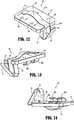
- adapter coupler 27 of loading unit 16includes an authentication board assembly 30 that is configured to be securely mounted within a recess 31 defined in adapter coupler 27.
- Authentication board assembly 30is positioned within adapter coupler 27 such that when loading unit 16 is secured to adapter assembly 14, authentication board assembly 30 engages an adapter board assembly 50 mounted within loading unit coupler 15 of the adapter assembly ( Fig. 11 ).
- authentication board 30includes a circuit board 37, a pair of contact members 40a, 40b (collectively, contact members 40) and a chip 36.
- Circuit board 37defines a substantially planar elongated member configured to be securely received within recess 31 defined by adapter coupler 27.
- Chip 36is in electrical communication with contact members 40.
- a distal end 37a of circuit board 37supports chip 36, and a proximal end 37b of circuit board 37 supports contact members 40.
- Distal end 37a of circuit board 37includes an alignment notch 33 defined therein that is configured to engage a corresponding alignment nub 32 provided at a distal end of recess 31 to ensure secure and accurate positioning of authentication board assembly 30 within adapter coupler 27.
- Chip 36includes any chip capable of storing the specifications of loading unit 16, such as, without limitation, cartridge size, staple arrangement, staple length, clamp-up distance, date of manufacture, expiration date, compatibility characteristics, a unique identifier (e.g., a serial number), and/or number of uses, and transmitting the specifications to handle assembly 12.
- chip 36includes an erasable programmable read only memory (“EPROM”) chip.
- EPROMerasable programmable read only memory
- the handle assembly 12may adjust the firing forces, firing stroke, and/or other operational characteristics thereof in accordance with the specifications of loading unit 16 that are transmitted from chip 36.
- chip 36may include write capabilities which allow handle assembly 12 to communicate to chip 36 that the associated loading unit 16 has been used, which can prevent reloading or reuse of an expended reload assembly, or any other unauthorized use.
- chip 36includes a secure authentication chip, such as, without limitation, a DS28E15 DeepCoverTM Secure Authenticator with 1-Wire SHA-256 and 512-Bit User EEPROM, manufactured by Maxim IntegratedTM of San Jose, California.
- a secure authentication chipsuch as, without limitation, a DS28E15 DeepCoverTM Secure Authenticator with 1-Wire SHA-256 and 512-Bit User EEPROM, manufactured by Maxim IntegratedTM of San Jose, California.
- the contents of chip 36, and the communications between chip 36 and handle assembly 12are encrypted to prevent unauthorized access.
- the use of low-quality counterfeit, re-manufactured, or "knock-off' loading unitsis effectively discouraged, which, in turn, reduces risk to patients by ensuring that only fresh, authentic loading units 16 are used during surgical procedures.
- chip 36utilizes a "1-wire" communications interface whereby a single signal conductor is employed, together with a ground conductor, for bidirectional serial communications between chip 36 and handle assembly 12.
- Contact assembly 38( Figs. 9, 10 ) includes a short contact arm 41 and a long contact arm 42 joined by a contact base 59, and having a generally elongated u-shaped configuration.
- Short contact arm 41includes a first contact member 40a orthogonally disposed and fixed to an upper portion of a proximal end thereof.
- Long contact arm 42includes a second contact member 40b orthogonally disposed and fixed to an upper portion of a proximal end thereof.
- Short and long contact arms 41, 42each include a solder tab 39 orthogonally disposed and fixed to a lower portion of a distal end thereof.
- Solder tabs 39are electromechanically joined to a proximal end 37b of circuit board 37 by, e.g., soldering, electrically conductive adhesive, and/or other suitable technique.
- Adapter coupler 27includes a raised contact support 34 extending radially from a proximal end thereof and includes a pair of cradles 35a, 35b defined therein that are configured to receive first contact member 40a and second contact member 40b, respectively, when authentication board assembly 30 is positioned within recess 31 of adapter coupler 27.
- a cover 43is configured to enclose and retain authentication board assembly 30 within recess 31 of adapter coupler 27 ( Figs. 7 and 8 ).
- short contact arm 41 and first contact member 40aare electrically insulated from long contact arm 42 and second contact member 40b by contact base 59.
- each of short contact arm 41 and long contact arm 42carries a separate circuit, e.g., short contact arm 41 carries signal and long contact arm 42 carries ground.
- short contact arm 41 and first contact member 40aare electrically joined with long contact arm 42 and second contact member 40b.
- short contact arm 41 and long contact arm 42operate in a bifurcated or redundant mode to carry a signal circuit, while the ground circuit is carried through other electrically conductive components of loading unit 16, adapter unit 14, and/or handle assembly 12.
- loading unit coupler 15includes an adapter board assembly 50 that is configured to be floatingly mounted within a pocket 60 defined in loading unit coupler 15.
- Adapter board assembly 50is positioned within loading unit coupler 15 such that when loading unit 16 is secured to adapter assembly 14, adapter board assembly 50 engages authentication board assembly 30.
- Adapter board assembly 50includes a circuit board 51 having a pair of contact members 55a, 55b (collectively, contact members 55) fixed thereto and in operable communication with handle assembly 12.
- contact members 55a, 55bare arranged for effective engagement in a transverse direction, e.g., transverse to the longitudinal axis "X-X" of stapler 10, to accommodate the rotational coupling of loading unit 16 and adapter assembly 14 as described herein.
- Circuit board 51includes an upper surface 51a, a lower surface 51b, a proximal end 51c, and a distal end 51d.
- Circuit board 51defines a substantially planar elongated member configured to be resiliently or floatingly received within pocket 60 defined by loading unit coupler 15.
- a spring clip 52is fixed to a proximal end 51c of circuit board 51 and is configured to support adapter board assembly 50 within pocket 60.
- Spring clip 52includes a pair of spring supports 54 having a wing-like configuration that are configured prevent spring clip 52 from over-extension and to provide stiffness thereto.
- Adapter board assembly 50includes a spring 53 having a broad, curvate u-shaped profile disposed on an upper surface 51a of circuit board 51.
- spring clip 52 and spring 53may be integrally formed.
- Spring clip 52 and/or spring 53may be positively aligned and/or supported by a notch 62 defined in proximal end 51c of circuit board 51.
- Circuit board 51includes one or more through holes 56 defined therein that may be utilized to form a conductive pathway between upper surface 51a and lower surface 51b of circuit board 51.
- adapter board assembly 50When adapter board assembly 50 is mounted within pocket 60, spring 53 bears against outer tube 57 of adapter assembly 14 ( Figs. 15, 16 ). In use, adapter board 50 is spring-biased towards authentication board assembly 30 by spring 53 and by side spring clip 52 such that, upon joining loading unit 16 and adapter assembly 14, any manufacturing tolerances between loading unit 16 and adapter assembly 14 are compensated for by engagement of the floating spring mount of adapter board 50 within pocket 60. In this manner, a reliable connection between contact members 55 of adapter board 50 and contact members 40 of authentication board assembly 30 is consistently achieved, thus providing a robust communication link between chip 36 and handle assembly 12. In some arrangements, contact assembly 38, contacts 40, and/or contacts 55 are formed at least in part from electrically conductive material, such as, without limitation, beryllium copper.
- FIGs. 15-21the interaction between adapter board assembly 50 and authentication board assembly 30 is shown.
- adapter board 50is retained within loading unit adapter 15 by spring clip 52.
- Spring 53bears against outer tube 57 to bias adapter board 50 inwardly towards bore 61, such that contact members 55 extend into bore 61.
- the initial rotational orientation of adapter coupler 27 and loading unit coupler 15is such that contact members 40 of authentication board 30 and contact members 55 of adapter board 50 are roughly 45° apart ( Fig. 20 ).
- contact members 40 of authentication board 30are brought into engagement with contact members 55 of adapter board 50.
- contact support 34 of adapter coupler 27 of loading unit 16provides radial support to contact members 30 as they engage mating contact members 55 of adapter board 50.
- spring 53bears against outer tube 57 which enables adapter board 50 to float with respect to authentication board 30 and loading unit coupler 15, thereby compensating for manufacturing variations between the various components and providing a reliable connection between authentication board 30 and adapter board 50.
- a loading unit like loading unit 16could have a removable and replaceable staple cartridge assembly.
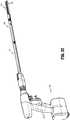
- a stapling systemis shown in FIGS. 22-57 , having a powered handle assembly 112 similar to the handle assembly 12 discussed above.
- the handle assemblyis configured as discussed above and has a controller 121a.
- the stapling systemincludes an adapter assembly 114 and a loading unit 116, each of which can be configured as discussed above.
- the loading unitis a linear stapling loading unit, but other types of loading units are contemplated.
- the loading unit 116has a drive assembly for firing staples into tissue clamped between the anvil jaw member 111 and staple cartridge jaw member 113, as discussed above.
- a removable and replaceable staple cartridge assembly 115Supported in the staple cartridge jaw member 113 is a removable and replaceable staple cartridge assembly 115.
- a removable and replaceable staple cartridge assemblyis disclosed in U.S. Patent Application No. 13/280,880, filed October 25, 2011 , and published as US 2013-0098965 A1 .
- Loading unit 116 of the present disclosureis configured to be used more than once.
- the loading unithas the removable staple cartridge assembly 115 that includes the staple cartridge and drive assembly discussed above.
- the removable assembly 116is configured to be removed and replaced (e.g., after firing staples or other surgical fasteners therefrom).
- the loading unit 116 shownincludes a proximal body portion 118 that is attachable to the adapter assembly 114.
- the features of the loading units of the present disclosurecan be incorporated in a surgical instrument in which does not include a detachable portion of the elongated portion of the instrument.
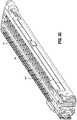
- Loading unit 500includes a proximal body portion 118 defining a longitudinal axis "A-A".
- Jaw membersinclude an anvil jaw member 111 and a cartridge jaw member 113.
- One of the jaw membersis pivotal in relation to the other to enable the clamping of tissue between the jaw members.
- the cartridge jaw member 113is pivotal in relation to the anvil jaw member and is movable between an open or unclamped position and a closed or approximated position.
- the anvil jaw member, or both the cartridge and anvil jaw membercan be movable.
- the anvil jaw memberincludes an anvil having a plurality of staple forming depressions.
- the cartridge jaw member 113includes a channel or carrier 120 which receives and supports the staple cartridge assembly 115.
- the cartridge assemblyhas a cartridge body 140 and a support plate 111.
- the cartridge body and support plateare attached to the channel or carrier 120 by a snap-fit connection, as discussed below, a detent, latch, or by another type of connection.
- the cartridge assemblyincludes fasteners or staples 141.
- Cartridge body 140defines a plurality of laterally spaced staple retention slots 142, which are configured as openings (see FIG. 32 ). Each slot is configured to receive a fastener or staple therein.
- Cartridge assemblyalso defines a plurality of cam wedge slots which accommodate staple pushers 146 and which are open on the bottom to allow the actuation sled 148 to pass longitudinally therethrough in the firing of the staples as discussed above.
- the removable staple cartridge assembly 115includes cartridge body 140 and support plate 111.
- the removable assembly 115is removable from channel 120, e.g., after staples have been fired from the cartridge body 140.
- Another removable and replaceable staple cartridge assemblyis capable of being loaded into the channel, such that the loading unit 116 can be actuated again to fire additional fasteners or staples.
- Channel 120includes one or a pair of engagement structures 120a (such as slots) for engaging the staple cartridge assembly and support plate (see FIG. 39 ), a central slot for the passage of the drive beam, a pair of proximal holes 150 for connection with the anvil jaw member, and a ramped surface 152.
- Proximal holes 150are configured to align with/mechanically engage a pair of corresponding holes or features on the anvil jaw member.
- the jaw memberscan be connected by pins, for example, to facilitate a pivotal relationship between anvil jaw member 111 and cartridge jaw member 113.
- the cartridge body 140includes a central slot 143, and rows of staple retention slots positioned on each side of slot 143 (see FIG. 32 ).
- Cartridge bodyalso includes a pair of engagement structures or protrusions which may, in certain arrangements, be slots or openings adjacent its proximal end for connection with the support plate 111a and/or channel 120.
- support plate 111aincludes a base 145, engagement features 147 and 147a (see FIG. 38 ) for connection with the cartridge body and/or channel, and a mounting portion 149 at a proximal end thereof (see FIG. 29 ).
- the support plate 111ais disposed underneath the cartridge body to support the staple pushers, actuation sled, and staples (or other surgical fasteners) and prevent those components from falling out of the staple cartridge assembly.
- the loading unitcan include a chip assembly 360 mounted on a proximal end of the proximal body portion 118, as shown in FIGS. 41-45 , for example.
- the chip assemblyis as described above in connection with the authentication board assembly 30 discussed above.
- the chip assembly 360is mounted for connection with a board assembly in the coupler on the distal end of the adapter assembly 114, and can be configured as discussed above in connection with FIGS. 1-21 .
- the chip assembly 360includes a chip 361 for authentication and information purposes, and can include a memory that stores certain information.
- the informationcan include the type of device the loading unit is, the version of the device/ loading unit, the name of the loading unit, the manufacturing lot number, the serial or other identification number, the maximum force to which the drive beam of the loading unit can be driven, the interlock zone (mm), the end zone (mm), whether or not the loading unit can articulate, and/or a usage limit (the number of times the loading unit can be used).
- the interlock zoneis the position of the drive beam, in millimeters, measured from the start or initial position of the drive beam, when the drive beam is engaged by a lockout in the loading unit.
- the end zoneis the position of the drive beam, in millimeters, measured from the start or initial position of the drive beam, when the drive beam has reached the end of its travel in the staple cartridge body 140. Since the staple cartridge assembly 115 can be removed and replaced, there is an intended limit to the number of times the loading unit can be reloaded with a fresh unfired staple cartridge.
- the information stored on the chipcan include the length of the staple line and/
- the controller 121a in the handle assembly 112can be programmed to read the information on the chip 361. This information is used in the operation of the surgical system. Desirably, some or all of the information is encrypted, which can be accomplished as discussed above in connection with FIGS. 1-21 .
- the controllercan be programmed to not provide power to a motor (not shown) disposed in the handle assembly 112, and not operate the adapter assembly and loading unit, in the event that the serial number or other data is not recognized.
- the maximum force informationis used in conjunction with a load sensor, such as a strain gauge, disposed in the surgical system.
- a load sensorcan be disposed in the adapter assembly 114 and/or loading unit, such as a load sensor on the drive beam.
- the controlleris programmed to compare the data from the load sensor to the maximum force data stored on the chip so that, for example, the operation of the motor (not shown) is interrupted before the maximum force is exceeded.
- the controllercan be programmed to operate in "slow mode" if the measured force reaches a predetermined level.
- the predetermined level of forcecan be the maximum force discussed above, or another level of force, stored on a chip in the system, such as chip 361.
- Slow modemeans that the controller operates the motor (not shown) at a slower rate, generating more torque, and also delaying the compression of tissue and/or firing of staples. In thick tissue, slow mode can allow fluid in the tissue to move away from the site of stapling, facilitating more compression of the tissue.
- the operation of the motorcan be stopped or operated in slow mode if the drive beam is disposed in the interlock zone or the end zone.
- the controllercan interrupt or prevent the operation of the articulation linkage, bar or cable if the data on chip 361 indicated that the loading unit does not articulate.
- the chip 361 with some or all of the data discussed abovecan be provided in any of the arrangements disclosed herein, including loading units that do not have a removable and replaceable staple cartridge assembly, and/or loading units that do not articulate.
- the information on chip 361can be read by the controller in the handle assembly, another chip in the system, or any other computer component in the surgical system.
- the controllercan write information to the chip on the loading unit. For example, the maximum force that was used to clamp onto tissue, as measured by the load sensor discussed above, the maximum force that was used to fire staples, and/or the position of the drive beam when the drive beam stops advancing, etc.
- Other information that can be written to the chip 361includes the location of the drive beam when the device entered into slow mode, the number of times the loading unit has been fired, whether the loading unit has been fired, the type of handle assembly, the serial number of the handle assembly, the type of adapter assembly, and/or the serial number of the adapter assembly.
- the maximum force to fire staplescan be saved along with the position of the drive beam, in any of the arrangements disclosed herein.
- the informationcan also be saved in a memory connected to the controller in the handle assembly, other chips in the system, or other computer components of the surgical system.
- an end effector or tool assemblyis arranged for articulating between a first position where tool assembly is aligned with longitudinal axis "Y-Y,” and a second position where tool assembly is disposed at an angle with respect to longitudinal axis "Y-Y.”
- the tool assemblywhich includes the anvil jaw member and the cartridge jaw member, may be mounted so as to be pivotable with respect to the proximal body portion 118.
- the anvil jaw member and cartridge jaw membercan be attached to a mounting assembly 2020 (discussed further below), and the mounting assembly can be pivotably connected to the proximal body portion 118.
- the loading unit 116includes one or more cables or linkages disposed in the proximal body portion so that when the cable or linkage is displaced, the tool assembly pivots and articulates with respect to the instrument. Further details of providing articulation are described in detail in commonly-owned U.S. Pat. No. 6,953,139 to Milliman et al .
- the adapter assembly 114can include a linkage, bar or cable for enabling the articulation of the tool assembly.
- any of the instruments disclosed hereincan include a cartridge body 140 having a stepped tissue-contacting surface 1412.
- different sized staplesor all the same sized staples, may be used.
- Further details of a staple cartridge having multiple staple sizesare included in U.S. Pat. No. 7,407,075 to Holsten et al.
- the staple forming recesses of the anvil, or the staple pushers, or both,can be configured accordingly, to form the staples in the desired shape and size.
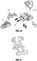
- the removable and replaceable staple cartridge assembly 115can further include a chip assembly 362. (see FIGS. 27 and 28 ).
- a corresponding board assembly 380( FIGS. 25 and 26 ) is disposed on the tool assembly of the loading unit 116, and may be disposed on the channel 120.
- the tool assembly board assembly 380can be configured as discussed above in connection with the adapter board assembly 50 of the adapter coupler 27.
- the tool assembly board assembly 380is configured to be securely mounted on a wall of the channel 120. This board assembly 380 is positioned such that when cartridge assembly 140 is secured to the channel 120 of the loading unit, the chip assembly 362 engages the board assembly 380 mounted on the channel. (See FIGS. 29-31 ).
- FIGS. 27 and 28show the relationship between the chip assembly and the staple cartridge body 140
- FIG.29shows the relationship between the chip assembly 362 and the support plate 111a.
- chip assemblyincludes a body 337 and a pair of contact members 340a, 340b (collectively, contact members 340) connected to a chip 336 disposed in the body.
- Body 337defines a rectangular member having flexible arms with snap features 337a thereon. The flexible arms are configured to be securely received within a recess 331 defined by in the cartridge body.
- Chip 336is in electrical communication with contact members 340.
- Chip 336includes any chip capable of storing information concerning the staple cartridge assembly 115.
- the chipcan be the same or similar to the chip of the authentication board assembly 30.
- any of the chipscan store information such as, without limitation, cartridge size, staple arrangement, staple line length (or length of the cartridge), date of manufacture, expiration date, compatibility characteristics, a unique identifier (e.g., a serial number), and/or number of uses, as well as whether or not the staple cartridge assembly has been used.
- Such informationcan be transmitted to the controller in the handle assembly 112, or to another computer component through an appropriate bus, pin connection, wireless means, etc.
- chip 336includes an erasable programmable read only memory (“EPROM”) chip.
- EPROMerasable programmable read only memory
- the controller in the handle assemblycan write information to the chip 336.
- the handle assembly 112may adjust the firing forces, firing stroke, and/or other operational characteristics thereof in accordance with the information concerning the staple cartridge assembly that are transmitted from chip 336.
- the handle assembly 112can communicate to chip 336 that the staple cartridge assembly has been used, which can prevent reloading or reuse of an expended reload assembly, or any other unauthorized use.
- the information stored in any of the components in the surgical systemcan be encrypted using private keys, public keys, and/or secure hash algorithms.
- the board assembly 380also has a pair of contacts 380a and 380b and a body 381.
- the board assemblyis mounted for contact with the chip assembly 362 when the staple cartridge assembly is properly mounted in the channel 120.
- the contacts 380a, 380b, 340a, and 340bhave an L-shaped configuration as seen in the figures so that they may resiliently engage one another.
- the body 381can define a snap feature 382 that is provided to engage a hole 383 in the channel to securely mount the board assembly.
- the board assemblyis appropriately connected to a bus, wires, or has a wireless communicator for transmittal of the information from chip assembly 362 to the controller in the handle assembly, or any other computer device.
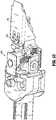
- a lockout mechanism 500is disposed in the loading unit.
- the loading unitmay be configured as discussed above.
- the present disclosureis directed to a removable assembly having the lockout, or a loading unit having the lockout.
- the lockout mechanism 500includes a latch 2010 and at least one spring 2030, and is configured to prevent re-firing of a staple cartridge assembly 115 or staple cartridge 26, and also prevent distal translation of a drive beam after the staple cartridge has been fired and prior to loading of another cartridge assembly 115.
- the lockout mechanism 500is shown alongside the sled 148 and mounting assembly 2020 in FIG. 50 .
- the at least one spring 2030is mounted on a distally facing surface 2031. For example, recesses are formed in surface 2031 for receiving springs 2030.
- Corresponding postsare provided on a proximally facing surface of the latch 2010.
- the latchis configured to be pivotable within the loading unit, and includes at least one prong 2012, a rear portion 2014, and a supporting portion 2016.
- the latchis configured to pivot around the supporting portion 2016, shown in FIGS. 50 and 51 as two downwardly depending features, and is biased by the spring or springs 2030.
- the sled 148has a hole or recess for receiving the at least one prong 2012 when the latch and drive beam are in their initial positions. (see FIG. 52 ).
- the drive beam 2039can interact with, or include, a dynamic clamping member 2040 having an upper flange 2042, lower flange 2044, and knife blade 2046. (see FIG. 53 ).
- the latch 2010In the initial position, the latch 2010 is biased in a forward or distal direction, with the rear portion 2014 in contact with an edge 2039a on the drive beam 2039, preventing further rotational movement of the latch.
- the dynamic clamping memberpushes the sled distally.
- a rear portion 148a of the sledpushes the prong or prongs 2012, tilting the latch against the bias of the at least one spring 2030. This removes the rear portion 2014 from the area near the edge 2039a, and allows the drive beam and dynamic clamping member to move forward.
- the latchrotates forwardly under the influence of the spring. (see FIG. 57 ).
- the dynamic clamping memberAfter the dynamic clamping member and sled have fired the staples from the cartridge 140, the dynamic clamping member is moved proximally, leaving the sled at the distal end of the cartridge 140 and cartridge assembly 115.
- the dynamic clamping membercan move past the latch 2010, as cam surface 2041 moves the latch out of the path of travel (see FIG. 57 ).
- the latch 2010will prevent another forward movement of the dynamic clamping member 2040.
- the latch rear portion 2014is in a position to engage another edge 2039b of the drive beam. (see FIG. 57 ).
- the cartridge assembly 115can be configured to return the latch 2010 to the initial position, so that the drive beam and dynamic clamping member can again be moved distally to fire another set of staples.
- any of the arrangements disclosed hereincan include a chip assembly 360 on a surgical stapling loading unit, like loading unit 116 that has information on it concerning the lockout mechanism, such as the lockout mechanism discussed above. Furthermore, information can be stored on the chip 361 concerning the lockout mechanism. For example, the fact that the lockout mechanism was engaged can be recorded in chip assembly 360 and/or chip assembly 362 by the controller in the handle.
- the controller in the handlecan include a memory for storing information, including a processor, and other computer components.
- the controllercan also include a current meter, or ammeter, to measure the current in the motor of the handle assembly.
- the controllercan be programmed to record the peak current reached during use of the loading unit and/or staple cartridge assembly, and can record that peak current on any of the chips or other computer components in the system.
- a peak current reached after the staples have been firedcan be an indication that the loading unit was attempted to be fired a second time before a fresh staple cartridge assembly was mounted in the loading unit.
- the lockout mechanismcan include a sensor such as, for example, on the latch. It is contemplated that the surgical system can include loading units that do not have a lockout mechanism like the one discussed above. The fact that the loading unit does not have a lockout mechanism can be stored in chip 361.
- the handle assemblycan also include an encoder that determines how many rotations of the motor output shaft have been made, which can be used to determine a position of drive bars, linkages, cables, etc., in the adapter assembly, the drive beam or firing bar in the loading unit, or other components. Alternatively, other sensors can be used to determine the position of various components in the surgical system.
- the adapter assembly disclosed hereinin any of the arrangements disclosed herein, can be configured as disclosed in U.S. Published Application No. 2011/0174099 A1 .
- the motor in the handle assemblyprovides a rotational output on a rotating shaft and the adapter is configured to transform that output to a linearly moving linkage or bar, and can also provide drive to an articulation linkage in the proximal body portion 118 of the loading unit 116.
- the handle assembly and/or adapter assemblycan be configured as disclosed in U.S. Published Application Nos. 2014/0012289 A1 and 2014/0110453 A1 .
- any of the embodiments disclosed hereincan include a force measurement and drive circuit, or be configured to be used with a component that has a force measurement and drive circuit.
- Surgical instruments for applying fastenersare known wherein the force exerted on an end-effector assembly by the motor drive mechanism has been estimated by motor current measurements.
- motor current measurementsthere may be sources of error in this measurement scheme that change with temperature, and there are uncertainties due to the differences in friction between one end-effector assembly and adapter combination and another end-effector assembly and adapter combination, which mean that the forces estimated by motor currents alone are variable in their reliability.
- a surgical instrumentincluding an adapter configured to operably couple the end-effector assembly to a motor drive mechanism and configured to directly measure a driving force in the adapter.
- the presently-disclosed surgical instrument embodimentsare capable of detecting excessive loads and/or preventing damage to the adapter and/or a handle assembly, which may increase reliability.
- Various embodiments of presently-disclosed surgical instrumentare also capable of collecting data related to tissue compression. The presently-disclosed surgical instrument embodiments are configured to accurately determine when a tissue end stop or end stop condition has been reached.
- Various embodiments of presently-disclosed surgical instrumentutilize an adapter configured with a strain gauge and a drive circuit.
- a strain gaugethe teachings of the present disclosure may also apply to a variety of sensing devices capable of providing an electrical output proportional to applied pressure.
- the drive circuitincludes a dedicated instrumentation amplifier, custom tuned 2-pole filter, low power mode switch, 12 bit analog-to-digital converter, and 32 bit microprocessor.
- the teachings of the present disclosuremay also apply to a variety of surgical devices that include an end-effector assembly and a shaft, e.g., devices that seal tissue.
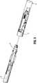
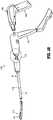
- FIG. 58shows a surgical instrument 1110 for use in various surgical procedures, e.g., endoscopic surgical procedures, and includes a motor pack 1150, a battery pack 1160, an adapter 1120, and a replaceable loading unit 1114 having an end-effector assembly 1111 configured to apply staples.
- Replaceable loading unit 1114 and/or the end-effector assembly 1111may include staples of various sizes and the staples may be arranged in one or more configurations.
- the replaceable loading unit 1114is configured to be releaseably coupled to a distal end of the adapter 1120.
- surgical instrument 1110includes a clamshell 1140 configured to hold the motor pack 1150 and the battery pack 1160, and includes a coupling mechanism 1130 for operably coupling the adapter 1120 via the clamshell 1140 to the motor pack 1150.
- Surgical instrument 1110may additionally, or alternatively, include a handle assembly (not shown) wherein the adapter 1120 extends from the distal end of the handle assembly.
- the instrument 1110may be provided with a transmission line (not shown) for connecting the instrument 1110 to an external power source.
- the driving forceis measured directly in the adapter 1120 using a strain gauge 1122, or other force sensor, and a drive circuit 1129 operably associated therewith.
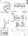
- Embodiments of the presently-disclosed surgical instrument 1110include factory-calibrated force measurements whereby the slope and offset correction factors are permanently stored in the microprocessor (e.g., microprocessor 1240 shown in FIGS. 59 and 60 ) of the drive circuit 1129.
- the microprocessore.g., microprocessor 1240 shown in FIGS. 59 and 60
- adapters 1120can be interchanged between different handle assemblies, or clamshells 1140, and the calibrated force measurements are assured.
- calibrated force measurements at the end of strokewill rise, which helps to allow for reliable end-stop detection.
- Force sensors and force transducersmay exhibit a drift of offset with temperature and over time.
- force transducersare calibrated at the factory during manufacture. This calibration provides correction factors to the microprocessor (e.g., microprocessor 1240 shown in FIGS. 59 and 60 ) for use by the microprocessor to modify the data received from the transducer (e.g., strain gauge 1122) to match the real world forces that are applied during factory manufacturing.
- the microprocessore.g., microprocessor 1240 shown in FIGS. 59 and 60
- the microprocessorto modify the data received from the transducer (e.g., strain gauge 1122) to match the real world forces that are applied during factory manufacturing.
- the slope correctionmay be calculated by first comparing "Sapp” to the ideal value "Si” that is the ideal output of the system with a force "Fl” input.
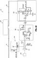
- FIGS. 59 and 60a circuit diagram of the drive circuit 1129 ( FIG. 58 ) is shown and includes an instrumentation amplifier 1220, a microprocessor 1240, an operational amplifier or "op-amp" 1230, and an interface 1215, which is connected to the strain gauge 1122, and power on/off circuit 1210 providing on/off capability.
- the drive circuit 1129further includes a voltage regulation circuit 1250, which provides clean DC voltage.
- voltage regulation circuit 1250provides a DC voltage of 3.3 volts.
- Instrumentation amplifier 1220is selected for power supply injection ratio and no current consumption. Instrumentation amplifier 1220 is designed to boost a relatively noisy signal or a very weak signal that comes from the strain gauge, e.g., boost the signal about 50 times.
- Op-amp 1230generally has low current draw and small size, and may be configured to boost the signal from the amplifier 1220 about 10 times. In some embodiments, op-amp 1230 provides 20 dB of gain with 20 Hz cut-off frequency, and may be a two pole Butterworth filter. Op-amp 1230 may also provide low-pass filtering, e.g., to reject motor noise, and/or may provide electromagnetic interference (EMI) suppression.
- EMIelectromagnetic interference
- the analog output of the op-amp 1230is transmitted via conductor 231 to the analog-to-digital input of the microprocessor 1240 and converted to digital form. Due to space constraints for housing the drive circuit 1129 within the adapter 1120, one of the main considerations in selecting an op-amp 1230 and a microprocessor 1240 is small size.
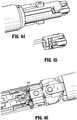
- FIG. 61is a flowchart illustrating a method of measuring a driving force in a surgical device in accordance with an embodiment of the present disclosure.
- a surgical instrument 1110is provided and includes an adapter 1120 configured to releaseably couple a replaceable loading unit 1114 having an end-effector assembly 1111 to a drive motor 1150.
- Adapter 1120includes a strain gauge 1122 coupled to a drive circuit 29 capable of detecting excessive loads.
- the end-effector assemblyis configured to apply staples.
- the drive circuit 1129includes a microprocessor 1240 and an op-amp 1230.
- Op-amp 1230may be configured to provide low-pass filtering and/or may be a two pole Butterworth filter.
- the method illustrated in FIG. 61may further include transmitting an analog output of the op-amp 1230 to an analog-to-digital input of the microprocessor 1240.
- Drive circuit 1129may further include a voltage regulation circuit 1250, which may provide a DC voltage of 3.3 volts.
- step 1420the strain gauge 1122 and the drive circuit 1129 are used to directly measure a driving force in the adapter 1120 to obtain a force measurement.
- step 1430if it is determined based on the force measurement that an excessive load has been detected, the driving force is adjusted to prevent damage to the adapter 1120.
- the method illustrated in FIG. 61may further include applying staples using the end-effector assembly and/or utilizing the end-effector assembly 1111 in endoscopic surgical procedures.
- the above-described surgical instruments and method of measuring a driving force in a surgical devicemay be suitable for utilization in endoscopic surgical procedures and/or suitable for utilization in open surgical applications.
- the motor in the handle assembly or clamshellmay be any electrical motor configured to actuate one or more drives (such as rotatable drive connectors).
- the motoris coupled to a battery, which may be a DC battery (e.g., rechargeable lead-based, nickel-based, lithium-ion based, battery etc.), an AC/DC transformer, or any other power source suitable for providing electrical energy to the motor.
Landscapes
- Health & Medical Sciences (AREA)
- Life Sciences & Earth Sciences (AREA)
- Surgery (AREA)
- General Health & Medical Sciences (AREA)
- Veterinary Medicine (AREA)
- Biomedical Technology (AREA)
- Heart & Thoracic Surgery (AREA)
- Medical Informatics (AREA)
- Molecular Biology (AREA)
- Animal Behavior & Ethology (AREA)
- Nuclear Medicine, Radiotherapy & Molecular Imaging (AREA)
- Public Health (AREA)
- Engineering & Computer Science (AREA)
- Physics & Mathematics (AREA)
- General Physics & Mathematics (AREA)
- Electromagnetism (AREA)
- Oral & Maxillofacial Surgery (AREA)
- Pathology (AREA)
- Chemical & Material Sciences (AREA)
- Analytical Chemistry (AREA)
- Surgical Instruments (AREA)
Description
- This application claims the benefit of and priority to
U.S. Provisional Patent Application No. 61/988,342, filed May 5, 2014 - The present disclosure relates to surgical devices having a reusable handle assembly and removable and replaceable components. More particularly, the present disclosure relates to an end-effector force measurement drive circuit suitable for use in a surgical instrument for applying fasteners.
- Powered surgical instruments for use in endoscopic procedures are known. Typically, such instruments include a reusable handle assembly, and a replaceable and generally disposable component sometimes referred to as single use loading unit or SULU. An adapter assembly connects the loading unit, which can include an end effector for interacting with tissue, to the handle assembly. In the case of a surgical stapler, the end effector can include a replaceable cartridge that is changed after each firing of the surgical stapler. To reduce costs and shorten procedure times, the handle assemblies are generally configured for use with a variety of loading units and/or assemblies of various configurations for use on tissue having different properties, e.g., thickness and density. For example, the different loading units may have staples of different sizes and/or the staples may be arranged in different configurations. To ensure the handle assembly is programmed to operate with the attached loading unit, some loading units are provided with an integrated circuit, also known as a chip, that communicates with the handle assembly to identify the configuration of the loading unit. This arrangement enables the configuration of the loading unit to be automatically conveyed to the handle assembly upon attachment of the loading unit to the adapter assembly, thereby eliminating user error or incompatibility that may be experienced when switching between loading units with different configurations.
- Surgical staplers are commonly used for stapling tissue within a body cavity where the end effector is likely to come in contact with fluids, e.g., blood, bile, and/or irrigation solutions. If the interconnections between the chip and the handle assembly are compromised, the chip could malfunction or data communications between the loading unit and the handle assembly could be disrupted, rendering the surgical stapler unstable or inoperable.
- Printed circuit boards (PCBs), sometimes referred to as printed wiring boards (PWBs) or etched wiring boards, are widely used in the assembly of discrete electrical components into operating circuits. PCBs generally provide a reliable and economical means of interconnecting electrical signals among system components. PCBs are available in a variety of different types and may be classified in a variety of ways.
- PCBs are generally used to mechanically support and electrically connect electronic components using electrically-conductive pathways or signal traces that conduct signals on the PCB. A typical PCB includes one or more layers of insulating material upon which patterns of electrical conductors are formed. In addition to a pattern of conductive traces on the PCB, a patterned array of metal-filled through-holes, or vias, may be formed to allow for layer-to-layer interconnections among various conductive features. A PCB on which electrical components are mounted is sometimes referred to as a printed circuit assembly (PCA) or a printed circuit board assembly (PCBA).
- Various kinds of electro surgical devices that employ PCBs have become thin and/or compact. In some devices, the amount of space needed to accommodate the PCBs may make it difficult to reduce the size of the devices. In some cases, PCB layouts large enough to accommodate the electrical components needed to provide desired functionality and/or performance may increase the overall size of the device and potentially hinder usability.
- Electrical signals may be used on PCBs for controlling the delivery of surgical staples to tissue. Surgical devices for applying staples, clips, or other fasteners to tissue are well known. Endoscopic surgical devices for applying surgical fasteners include an actuation unit, i.e., a handle assembly for actuating the device and a shaft for endoscopic access, and an end-effector assembly disposed at a distal end of the shaft. Certain of these devices are designed for use with a replaceable loading unit which includes the end-effector assembly and houses the staples or fasteners. The replaceable loading unit may include staples of various sizes and the staples may be arranged in one or more configurations. After firing the stapler with a replaceable loading unit, the user may remove the empty loading unit, select and attach to the stapler another loading unit having staples of the same or different size and the same or different staple arrangement, and fire the stapler again. This process may be performed repeatedly during a surgical procedure.
- During a surgical procedure, when the end-effector assembly is clamping down on tissue, or firing, in some situations it may be unclear whether the end-effector assembly has hit a piece of cartilage, and the surgeon may not be sure if he wants to go further. In some cases, when the end-effector assembly has hit something that blocks it from firing or that the motor drive has to overcome, the instrument draws excessive current which can be detected and measured. However, motor current measurements may not be entirely reliable, such as when the end-effector assembly has hit another staple line or encountered a malformed series of staples.
- Document
US 2011/0017801 discloses a surgical instrument for applying fasteners, the instrument comprising a handle assembly, a drive motor disposed within the handle assembly, a replaceable loading unit having and end-effector assembly and an adapter configured to releaseably couple the replaceable loading unit to the drive motor via the handle assembly. The adapter includes a strain gauge having a drive circuit coupled thereto, wherein the strain gauge and the drive circuit are configured to directly measure a driving force in the adapter, the instrument further comprising a microprocessor in communication with the drive circuit. - According to the present invention, a surgical instrument for applying fasteners is provided and includes a handle assembly or a clamshell, a drive motor disposed within the handle assembly or the clamshell, a replaceable loading unit having an end-effector assembly, and an adapter configured to releaseably couple the replaceable loading unit to the drive motor. The adapter is configured for interchangeable coupling to different handle assemblies or clamshells and includes a strain gauge having a drive circuit coupled thereto. The strain gauge and the drive circuit are configured to directly measure a driving force in the adapter. The drive circuit includes a microprocessor, wherein factory-calibrated force measurements including slope and offset correction factors are permanently stored in the microprocessor.
- According to another aspect of the present disclosure, a method of measuring a driving force in a surgical device includes providing a surgical instrument for applying fasteners including an adapter configured to releaseably couple a replaceable loading unit having an end-effector assembly to a drive motor. The adapter includes a strain gauge coupled to a drive circuit capable of detecting excessive loads. The method also includes using the strain gauge and the drive circuit to directly measure a driving force in the adapter to obtain a force measurement and if it is determined based on the force measurement that an excessive load has been detected, adjusting the driving force to prevent damage to the adapter.
- According to any one of the preceding aspects, the drive circuit further includes a voltage regulation circuit configured to provide a DC voltage.
- The above and other aspects, features, and advantages of the present disclosure will become more apparent in light of the following detailed description when taken in conjunction with the accompanying drawings in which:
Fig. 1 is a perspective view of a surgical stapling device for use with a chip assembly according to an arrangement of the present disclosure;Fig. 2 is a perspective view of the surgical stapling device ofFig. 1 showing the handle assembly, adapter assembly, and loading unit in a separated configuration;Fig. 3 is a view of a proximal end of a loading unit and a distal end of an adapter assembly of the surgical stapling device shown inFig. 1 ;Fig. 4 is an enlarged view of the proximal end of the loading unit and the distal end of the adapter assembly shown inFig. 3 ;Fig. 5 is another enlarged view of the proximal end of the loading unit and the distal end of the adapter assembly shown inFig. 3 ;Fig. 6 is an enlarged, exploded view of the proximal end of the loading unit shown inFig. 3 with the loading unit and authentication board separated;Fig. 7 is an enlarged, partially-exploded view of the proximal end of the loading unit shown inFig. 3 with the authentication board cover separated from the loading unit;Fig. 8 is an enlarged view of the proximal end of the loading unit shown inFig. 3 ;Fig. 9 is a perspective view of an authentication board assembly according to a further arrangement;Fig. 10 is a perspective view of an authentication board contact;Fig. 11 is an enlarged, exploded view of the distal end of the adapter assembly shown inFig. 3 with the adapter assembly and adapter board separated;Fig. 12 is an enlarged view of the adapter board shown inFig. 11 ;Fig. 13 is another enlarged view of the adapter board shown inFig. 11 ;Fig. 14 is yet another enlarged view of the adapter board shown inFig. 11 ;Fig. 15 is a cross-sectional, side view of the adapter assembly shown inFig. 3 showing the adapter assembly separated from the loading unit;Fig. 16 is an enlarged view of the indicated area shown inFig. 15 showing the adapter board separated from the authentication board;Fig. 17 is a cross-sectional, side view of the adapter assembly shown inFig. 3 showing the adapter assembly engaged with the loading unit;Fig. 18 is an enlarged view of the indicated area shown inFig. 17 showing the adapter board engaged with the authentication board;Fig. 19 is a cross-sectional, axial view of the adapter assembly shown inFig. 3 showing the adapter assembly separated from the loading unit;Fig. 20 is a cross-sectional, axial view of the adapter assembly shown inFig. 3 showing the loading unit inserted into the adapter assembly; andFig. 21 is a cross-sectional, axial view of the adapter assembly shown inFig. 3 showing the loading unit engaged with the adapter assembly.Fig. 22 is a perspective view of a surgical stapling device according to a further arrangement;Fig. 23 is a perspective view of a loading unit according to a further arrangement;Fig. 24 is the loading unit ofFig. 23 shown with parts separated;Fig. 25 is a detailed perspective view of a board assembly;Fig. 26 is a another detailed perspective view of the board assembly ofFig. 25 ;Fig. 27 is a detailed perspective view of a chip assembly;Fig. 28 is another detailed perspective view of the chip assembly ofFig. 27 ;Fig. 29 is a detailed perspective view of a support plate;Fig. 30 is a perspective view of the chip assembly and board assembly ofFigs. 25-28 ;Fig. 31 is another perspective view of the chip assembly and board assembly ofFigs. 25-28 ;Fig. 32 is a top perspective view of a staple cartridge assembly;Fig. 33 is a top perspective view of the staple cartridge assembly ofFig. 32 , with a shipping wedge;Fig. 34 is a bottom perspective view of the shipping wedge ofFig. 33 ;Fig. 35 is a detailed perspective view of a lockout assembly;Fig. 36 is a perspective view of the loading unit ofFig. 23 showing the staple cartridge assembly;Fig. 37 is a top view of the loading unit with the anvil and shipping wedge removed;Fig. 38 is a perspective view of the proximal portion of a support plate of the staple cartridge assembly;Fig. 39 is a perspective view of the proximal portion of a channel of the loading unit;Fig. 40 is a cross sectional view of the loading unit;Fig. 41 is a perspective view of a chip assembly of the loading unit with parts separated;Fig. 42 is a perspective view of the proximal portion of the loading unit;Fig. 43 is a perspective view of the chip assembly;Fig. 44 is a perspective view of the proximal portion of the loading unit;Fig. 45 is another perspective view of the chip assembly;Fig. 46 is a detailed perspective view of a lockout assembly;Fig. 47 is another detailed perspective view of a lockout mechanism;Fig. 48 is a cross sectional view through the drive beam;Fig. 49 is a another detailed perspective view of the lockout mechanism;Fig. 50 is a perspective view with parts separated showing a latch, sled, and mounting portion;Fig. 51 is a perspective view of the latch;Fig. 52 is a perspective view of the loading unit with parts removed showing the lockout mechanism;Fig. 53 is a perspective view of the lockout mechanism with parts separated showing the drive beam;Fig. 54 is a cross sectional view taken longitudinally through the loading unit;Fig. 55 is a detailed view ofFig. 54 showing the latch and dynamic clamping member;Fig. 56 is a side view of the drive beam, dynamic clamping member, and sled;Fig. 57 is a side view of the drive beam, dynamic clamping member, and sled, with the drive beam and dynamic clamping member advanced;FIG. 58 is a perspective view of a surgical instrument for applying surgical staples, shown with parts separated, including an adapter configured with a strain gauge and a drive circuit according to the present invention;FIG. 59 is a circuit diagram of the drive circuit ofFIG. 1 according to an embodiment of the present invention;FIG. 60 is a circuit diagram showing the microprocessor ofFIG. 2 and a voltage regulation circuit according to an embodiment of the present invention ; andFIG. 61 is a flowchart illustrating a method of measuring a driving force in a surgical device in accordance with an embodiment of the present invention- Hereinafter, embodiments of the presently-disclosed surgical instrument including an adapter configured with a strain gauge and a drive circuit and method of measuring a driving force in a surgical device are described with reference to the accompanying drawings. Like reference numerals may refer to similar or identical elements throughout the description of the figures. Particular embodiments of the present disclosure are described hereinbelow with reference to the accompanying drawings; however, it is to be understood that the disclosed embodiments are merely examples of the disclosure, which may be embodied in various forms. Well-known and/or repetitive functions and constructions are not described in detail to avoid obscuring the present disclosure in unnecessary or redundant detail. Therefore, specific structural and functional details disclosed herein are not to be interpreted as limiting, but merely as a basis for the claims and as a representative basis for teaching one skilled in the art to variously employ the present disclosure in virtually any appropriately detailed structure. As is common in the art, the term "proximal" refers to that part or component closer to the user or operator, i.e. surgeon or clinician, while the term "distal" refers to that part or component further away from the user. In addition, as used herein in the description and in the claims, terms referencing orientation, e.g., "top", "bottom", "upper", "lower", "left", "right", and the like, are used with reference to the figures and features shown and described herein. It is to be understood that embodiments in accordance with the present disclosure may be practiced in any orientation without limitation. In this description, as well as in the drawings, like-referenced numbers represent elements which may perform the same, similar, or equivalent functions. Embodiments of the presently disclosed chip assembly will now be described in detail with reference to the drawings in which like reference numerals designate identical or corresponding elements in each of the several views. The word "exemplary" is used herein to mean "serving as an example, instance, or illustration." Any embodiment described herein as "exemplary" is not necessarily to be construed as preferred or advantageous over other embodiments. The word "example" may be used interchangeably with the term "exemplary."
- This description may use the phrases "in an embodiment," "in embodiments," "in some embodiments," or "in other embodiments," which may each refer to one or more of the same or different embodiments in accordance with the present disclosure.
- As used herein, the terms "power source" and "power supply" refer to any source of electrical power, e.g., electrical outlet, a/c generator, battery or battery pack, etc. As it is used in this description, "electrically conductive," or simply "conductive," generally refers to materials that are capable of electrical conductivity, including, without limitation, materials that are highly conductive, e.g., metals and alloys, or materials that are semi-conductive, e.g., semi-conducting materials and composites. As it is used in this description, "transmission line" generally refers to any transmission medium that can be used for the propagation of signals from one point to another.
- With reference initially to
Figs. 1 and 2 , a surgical stapling instrument including an authentication system according to the present disclosure is shown generally asstapler 10.Stapler 10 includes ahandle assembly 12, anadapter assembly 14 extending distally fromhandle assembly 12, and aloading unit 16 selectively secured to a distal end ofadapter assembly 14. A detailed description ofhandle assembly 12,adapter assembly 14, andloading unit 16 is provided in commonly-owned U.S. Patent Appl. Publ. No.2012/008913 1 . - Handle
assembly 12 includes alower housing portion 17, anintermediate housing portion 18 extending from and/or supported onlower housing portion 17, and anupper housing portion 19 extending from and/or supported onintermediate housing portion 18.Intermediate housing portion 18 andupper housing portion 19 are separated into a distal half-section 20a that is integrally formed with, and extends from, thelower housing portion 17, and a proximal half-section 20b joined to distal half-section 20a by any suitable manner of attachment, such as without limitation, ultrasonic welding and/or a plurality of fasteners. When joined, distal and proximal half-sections handle housing 21 defining a cavity therein which houses a circuit board that includes acontroller 21a, and a drive mechanism (not shown). Lower housing portion 17 includes adoor 13 pivotally connected thereto for accessing a cavity formed inlower housing portion 17 for retaining a battery (not shown) therein. It is contemplated thatstapler 10 may be powered by any number of power sources, such as, for example and without limitation, a fuel cell, a power cord connected to an external power source, and so forth.Adapter assembly 14 includes adrive coupler 22 at a proximal end thereof and aloading unit coupler 15 at a distal end thereof. Distal half-section 20a ofupper housing portion 19 defines a nose or connectingportion 11 configured to operably receivedrive coupler 22 ofadapter assembly 14.Loading unit 16 includes anadapter coupler 27 configured to operably receiveloading unit coupler 15 ofadapter assembly 14.Upper housing portion 19 ofhandle housing 21 encloses a drive mechanism (not shown) configured to drive shafts and/or gear components (not shown) in order to perform the various operations ofstapler 10. In particular, the drive mechanism is configured to drive shafts and/or gear components in order to selectively move a tool assembly orend effector 23 ofloading unit 16 relative to aproximal body portion 24 ofloading unit 16, to rotateloading unit 16 about a longitudinal axis "X-X" (Fig. 1 ) relative to handlehousing 21, to move ananvil assembly 25 relative tocartridge assembly 26 ofloading unit 16, and/or to fire a stapling and cutting cartridge withincartridge assembly 26 ofloading unit 16.- The
loading unit 16 shown in theFIGS. 1-21 is a linear surgical stapling loading unit. The loading unit includes a stapling anvil with recesses for forming surgical staples that are driven against it by operation of the loading unit in the surgical system. A staple cartridge houses the surgical staples, as well as the staple firing and/or driving assembly. The staple firing and/or driving assembly is known. One such assembly is described inU.S. Patent Nos. 8,256,656 and7,044,53 . The drive assembly includes an elongated drive beam having a knife blade. The drive beam pushes an actuation sled having wedge shaped surfaces for interacting with pushers. The pushers support the staples and have camming surfaces that the sled wedge shaped surfaces slide against, driving the pushers upwardly while the sled is advanced in a longitudinal fashion through the staple cartridge. - It is contemplated that the loading unit has jaw members for supporting the anvil and the staple cartridge respectively. The anvil jaw member and staple cartridge jaw member can be approximated to clamp tissue therebetween. It is also contemplated that the end effector can articulate or pivot off axis from the longitudinal axis defined by the
proximal body portion 24. - It is contemplated that the loading unit can be a circular surgical stapling unit, other types of stapling units, or other types of surgical end effectors, such as electrocautery, ablation, ultrasonic, etc.
- With reference to
Figs. 3 ,4, and 5 ,loading unit coupler 15 ofadapter assembly 14 is configured to operably engageadapter coupler 27 ofloading unit 16 via a push and twist or bayonet-type arrangement.Adapter coupler 27 includes one or more bayonet lugs 28 that are configured to mate with corresponding one ormore bayonet channels 29 defined in abayonet collar 48 provided byloading unit coupler 15 ofadapter assembly 14. Ashort link member 44 and aload link member 45 are longitudinally disposed withinadapter assembly 14 and are configured to translate longitudinally (e.g., distally and proximally) during operation ofstapler 10. Acam 55 disposed at a distal end ofshort link member 44 is urged distally against abayonet channel 29 byspring 49a. To engageloading unit 16 withadapter assembly 14,adapter coupler 27 ofloading unit 16 is inserted intoloading unit coupler 15 ofadapter assembly 14 and rotated. In turn,bayonet collar 48 rotates cooperatively withadapter coupler 27. Asbayonet collar 48 rotates,cam 55 rides offbayonet channel 29, causingshort link member 44 to translate distally, which, in turn, causes aswitch tab 47 formed inshort link member 44 to actuateswitch 46.Switch 46 is in operative electrical communication with thecontroller 21a and is configured to convey thereto the engagement status betweenloading unit 16 andadapter assembly 14. - Turning now to
Figs. 6-10 ,adapter coupler 27 ofloading unit 16 includes anauthentication board assembly 30 that is configured to be securely mounted within arecess 31 defined inadapter coupler 27.Authentication board assembly 30 is positioned withinadapter coupler 27 such that when loadingunit 16 is secured toadapter assembly 14,authentication board assembly 30 engages anadapter board assembly 50 mounted withinloading unit coupler 15 of the adapter assembly (Fig. 11 ). In more detail,authentication board 30 includes acircuit board 37, a pair ofcontact members chip 36.Circuit board 37 defines a substantially planar elongated member configured to be securely received withinrecess 31 defined byadapter coupler 27.Chip 36 is in electrical communication withcontact members 40. Adistal end 37a ofcircuit board 37 supportschip 36, and aproximal end 37b ofcircuit board 37 supportscontact members 40.Distal end 37a ofcircuit board 37 includes analignment notch 33 defined therein that is configured to engage acorresponding alignment nub 32 provided at a distal end ofrecess 31 to ensure secure and accurate positioning ofauthentication board assembly 30 withinadapter coupler 27. Chip 36 includes any chip capable of storing the specifications ofloading unit 16, such as, without limitation, cartridge size, staple arrangement, staple length, clamp-up distance, date of manufacture, expiration date, compatibility characteristics, a unique identifier (e.g., a serial number), and/or number of uses, and transmitting the specifications to handleassembly 12. In some arrangements,chip 36 includes an erasable programmable read only memory ("EPROM") chip. In this manner, thehandle assembly 12 may adjust the firing forces, firing stroke, and/or other operational characteristics thereof in accordance with the specifications ofloading unit 16 that are transmitted fromchip 36. It is further envisioned thatchip 36 may include write capabilities which allowhandle assembly 12 to communicate to chip 36 that the associatedloading unit 16 has been used, which can prevent reloading or reuse of an expended reload assembly, or any other unauthorized use.- In some arrangements,
chip 36 includes a secure authentication chip, such as, without limitation, a DS28E15 DeepCoverTM Secure Authenticator with 1-Wire SHA-256 and 512-Bit User EEPROM, manufactured by Maxim IntegratedTM of San Jose, California. In these arrangements, the contents ofchip 36, and the communications betweenchip 36 and handleassembly 12, are encrypted to prevent unauthorized access. In this manner, the use of low-quality counterfeit, re-manufactured, or "knock-off' loading units is effectively discouraged, which, in turn, reduces risk to patients by ensuring that only fresh,authentic loading units 16 are used during surgical procedures. In addition, the likelihood that medical facilities and/or surgeons may unwittingly use counterfeit loading units is greatly curtailed, thus reducing the overall costs to society for delivering medical services. In some arrangements,chip 36 utilizes a "1-wire" communications interface whereby a single signal conductor is employed, together with a ground conductor, for bidirectional serial communications betweenchip 36 and handleassembly 12. - Contact assembly 38 (
Figs. 9, 10 ) includes ashort contact arm 41 and along contact arm 42 joined by acontact base 59, and having a generally elongated u-shaped configuration.Short contact arm 41 includes afirst contact member 40a orthogonally disposed and fixed to an upper portion of a proximal end thereof.Long contact arm 42 includes asecond contact member 40b orthogonally disposed and fixed to an upper portion of a proximal end thereof. Short andlong contact arms solder tab 39 orthogonally disposed and fixed to a lower portion of a distal end thereof.Solder tabs 39 are electromechanically joined to aproximal end 37b ofcircuit board 37 by, e.g., soldering, electrically conductive adhesive, and/or other suitable technique. Adapter coupler 27 includes a raisedcontact support 34 extending radially from a proximal end thereof and includes a pair ofcradles first contact member 40a andsecond contact member 40b, respectively, whenauthentication board assembly 30 is positioned withinrecess 31 ofadapter coupler 27. Acover 43 is configured to enclose and retainauthentication board assembly 30 withinrecess 31 of adapter coupler 27 (Figs. 7 and8 ).- In some arrangements,
short contact arm 41 andfirst contact member 40a are electrically insulated fromlong contact arm 42 andsecond contact member 40b bycontact base 59. In these arrangements, each ofshort contact arm 41 andlong contact arm 42 carries a separate circuit, e.g.,short contact arm 41 carries signal andlong contact arm 42 carries ground. In other embodiments,short contact arm 41 andfirst contact member 40a are electrically joined withlong contact arm 42 andsecond contact member 40b. In these arrangements,short contact arm 41 andlong contact arm 42 operate in a bifurcated or redundant mode to carry a signal circuit, while the ground circuit is carried through other electrically conductive components ofloading unit 16,adapter unit 14, and/or handleassembly 12. - As mentioned above,
authentication board assembly 30 is configured to engageadapter board assembly 50 mounted withinloading unit coupler 15 when loadingunit 16 is secured toadapter assembly 14. With reference now toFigs. 11-14 ,loading unit coupler 15 includes anadapter board assembly 50 that is configured to be floatingly mounted within apocket 60 defined inloading unit coupler 15.Adapter board assembly 50 is positioned withinloading unit coupler 15 such that when loadingunit 16 is secured toadapter assembly 14,adapter board assembly 50 engagesauthentication board assembly 30. Adapter board assembly 50 includes acircuit board 51 having a pair ofcontact members handle assembly 12. In the illustrated arrangement,contact members stapler 10, to accommodate the rotational coupling ofloading unit 16 andadapter assembly 14 as described herein.Circuit board 51 includes anupper surface 51a, alower surface 51b, aproximal end 51c, and adistal end 51d.Circuit board 51 defines a substantially planar elongated member configured to be resiliently or floatingly received withinpocket 60 defined byloading unit coupler 15. Aspring clip 52 is fixed to aproximal end 51c ofcircuit board 51 and is configured to supportadapter board assembly 50 withinpocket 60.Spring clip 52 includes a pair of spring supports 54 having a wing-like configuration that are configured preventspring clip 52 from over-extension and to provide stiffness thereto.Adapter board assembly 50 includes aspring 53 having a broad, curvate u-shaped profile disposed on anupper surface 51a ofcircuit board 51. In some arrangements,spring clip 52 andspring 53 may be integrally formed.Spring clip 52 and/orspring 53 may be positively aligned and/or supported by anotch 62 defined inproximal end 51c ofcircuit board 51.Circuit board 51 includes one or more throughholes 56 defined therein that may be utilized to form a conductive pathway betweenupper surface 51a andlower surface 51b ofcircuit board 51.- When
adapter board assembly 50 is mounted withinpocket 60,spring 53 bears againstouter tube 57 of adapter assembly 14 (Figs. 15, 16 ). In use,adapter board 50 is spring-biased towardsauthentication board assembly 30 byspring 53 and byside spring clip 52 such that, upon joiningloading unit 16 andadapter assembly 14, any manufacturing tolerances betweenloading unit 16 andadapter assembly 14 are compensated for by engagement of the floating spring mount ofadapter board 50 withinpocket 60. In this manner, a reliable connection betweencontact members 55 ofadapter board 50 andcontact members 40 ofauthentication board assembly 30 is consistently achieved, thus providing a robust communication link betweenchip 36 and handleassembly 12. In some arrangements,contact assembly 38,contacts 40, and/orcontacts 55 are formed at least in part from electrically conductive material, such as, without limitation, beryllium copper. - Turning now to
Figs. 15-21 , the interaction betweenadapter board assembly 50 andauthentication board assembly 30 is shown. As seen inFigs. 15, 16 , and19 ,adapter board 50 is retained withinloading unit adapter 15 byspring clip 52.Spring 53 bears againstouter tube 57 tobias adapter board 50 inwardly towardsbore 61, such thatcontact members 55 extend intobore 61. Asadapter coupler 27 is inserted fully intobore 61 ofloading unit adapter 15, the initial rotational orientation ofadapter coupler 27 andloading unit coupler 15 is such thatcontact members 40 ofauthentication board 30 andcontact members 55 ofadapter board 50 are roughly 45° apart (Fig. 20 ). Asloading unit 16 is rotated with respect toadapter assembly 14,contact members 40 ofauthentication board 30 are brought into engagement withcontact members 55 ofadapter board 50. Advantageously,contact support 34 ofadapter coupler 27 ofloading unit 16 provides radial support to contactmembers 30 as they engagemating contact members 55 ofadapter board 50. In addition,spring 53 bears againstouter tube 57 which enablesadapter board 50 to float with respect toauthentication board 30 andloading unit coupler 15, thereby compensating for manufacturing variations between the various components and providing a reliable connection betweenauthentication board 30 andadapter board 50. - It is contemplated that a loading unit like
loading unit 16 could have a removable and replaceable staple cartridge assembly. A stapling system is shown inFIGS. 22-57 , having apowered handle assembly 112 similar to thehandle assembly 12 discussed above. The handle assembly is configured as discussed above and has acontroller 121a. The stapling system includes anadapter assembly 114 and aloading unit 116, each of which can be configured as discussed above. The loading unit is a linear stapling loading unit, but other types of loading units are contemplated. Theloading unit 116 has a drive assembly for firing staples into tissue clamped between theanvil jaw member 111 and staplecartridge jaw member 113, as discussed above. - Supported in the staple
cartridge jaw member 113 is a removable and replaceablestaple cartridge assembly 115. A removable and replaceable staple cartridge assembly is disclosed inU.S. Patent Application No. 13/280,880, filed October 25, 2011 US 2013-0098965 A1 . Loading unit 116 of the present disclosure is configured to be used more than once. In particular, the loading unit has the removablestaple cartridge assembly 115 that includes the staple cartridge and drive assembly discussed above. Theremovable assembly 116 is configured to be removed and replaced (e.g., after firing staples or other surgical fasteners therefrom). Theloading unit 116 shown includes aproximal body portion 118 that is attachable to theadapter assembly 114. However, the features of the loading units of the present disclosure can be incorporated in a surgical instrument in which does not include a detachable portion of the elongated portion of the instrument.- Loading unit 500 includes a
proximal body portion 118 defining a longitudinal axis "A-A". Jaw members include ananvil jaw member 111 and acartridge jaw member 113. One of the jaw members is pivotal in relation to the other to enable the clamping of tissue between the jaw members. In the illustrated arrangements, thecartridge jaw member 113 is pivotal in relation to the anvil jaw member and is movable between an open or unclamped position and a closed or approximated position. However, the anvil jaw member, or both the cartridge and anvil jaw member, can be movable. As discussed in connection withFIGS. 1-21 , the anvil jaw member includes an anvil having a plurality of staple forming depressions. - The
cartridge jaw member 113 includes a channel orcarrier 120 which receives and supports thestaple cartridge assembly 115. The cartridge assembly has acartridge body 140 and asupport plate 111. The cartridge body and support plate are attached to the channel orcarrier 120 by a snap-fit connection, as discussed below, a detent, latch, or by another type of connection. The cartridge assembly includes fasteners orstaples 141.Cartridge body 140 defines a plurality of laterally spacedstaple retention slots 142, which are configured as openings (seeFIG. 32 ). Each slot is configured to receive a fastener or staple therein. Cartridge assembly also defines a plurality of cam wedge slots which accommodatestaple pushers 146 and which are open on the bottom to allow theactuation sled 148 to pass longitudinally therethrough in the firing of the staples as discussed above. - The removable
staple cartridge assembly 115 includescartridge body 140 andsupport plate 111. Theremovable assembly 115 is removable fromchannel 120, e.g., after staples have been fired from thecartridge body 140. Another removable and replaceable staple cartridge assembly is capable of being loaded into the channel, such that theloading unit 116 can be actuated again to fire additional fasteners or staples. Channel 120 includes one or a pair ofengagement structures 120a (such as slots) for engaging the staple cartridge assembly and support plate (seeFIG. 39 ), a central slot for the passage of the drive beam, a pair of proximal holes 150 for connection with the anvil jaw member, and a ramped surface 152. Proximal holes 150 are configured to align with/mechanically engage a pair of corresponding holes or features on the anvil jaw member. The jaw members can be connected by pins, for example, to facilitate a pivotal relationship betweenanvil jaw member 111 andcartridge jaw member 113.- The
cartridge body 140 includes a central slot 143, and rows of staple retention slots positioned on each side of slot 143 (seeFIG. 32 ). Cartridge body also includes a pair of engagement structures or protrusions which may, in certain arrangements, be slots or openings adjacent its proximal end for connection with thesupport plate 111a and/orchannel 120. - With particular reference to
FIG. 29 ,support plate 111a includes abase 145, engagement features 147 and 147a (seeFIG. 38 ) for connection with the cartridge body and/or channel, and a mountingportion 149 at a proximal end thereof (seeFIG. 29 ). Thesupport plate 111a is disposed underneath the cartridge body to support the staple pushers, actuation sled, and staples (or other surgical fasteners) and prevent those components from falling out of the staple cartridge assembly. - The loading unit can include a
chip assembly 360 mounted on a proximal end of theproximal body portion 118, as shown inFIGS. 41-45 , for example. The chip assembly is as described above in connection with theauthentication board assembly 30 discussed above. Thechip assembly 360 is mounted for connection with a board assembly in the coupler on the distal end of theadapter assembly 114, and can be configured as discussed above in connection withFIGS. 1-21 . Thechip assembly 360 includes achip 361 for authentication and information purposes, and can include a memory that stores certain information. The information can include the type of device the loading unit is, the version of the device/ loading unit, the name of the loading unit, the manufacturing lot number, the serial or other identification number, the maximum force to which the drive beam of the loading unit can be driven, the interlock zone (mm), the end zone (mm), whether or not the loading unit can articulate, and/or a usage limit (the number of times the loading unit can be used). The interlock zone is the position of the drive beam, in millimeters, measured from the start or initial position of the drive beam, when the drive beam is engaged by a lockout in the loading unit. The end zone is the position of the drive beam, in millimeters, measured from the start or initial position of the drive beam, when the drive beam has reached the end of its travel in thestaple cartridge body 140. Since thestaple cartridge assembly 115 can be removed and replaced, there is an intended limit to the number of times the loading unit can be reloaded with a fresh unfired staple cartridge. The information stored on the chip can include the length of the staple line and/or cartridge. - The
controller 121a in thehandle assembly 112 can be programmed to read the information on thechip 361. This information is used in the operation of the surgical system. Desirably, some or all of the information is encrypted, which can be accomplished as discussed above in connection withFIGS. 1-21 . The controller can be programmed to not provide power to a motor (not shown) disposed in thehandle assembly 112, and not operate the adapter assembly and loading unit, in the event that the serial number or other data is not recognized. The maximum force information is used in conjunction with a load sensor, such as a strain gauge, disposed in the surgical system. For example, a load sensor can be disposed in theadapter assembly 114 and/or loading unit, such as a load sensor on the drive beam. The controller is programmed to compare the data from the load sensor to the maximum force data stored on the chip so that, for example, the operation of the motor (not shown) is interrupted before the maximum force is exceeded. In another example, the controller can be programmed to operate in "slow mode" if the measured force reaches a predetermined level. The predetermined level of force can be the maximum force discussed above, or another level of force, stored on a chip in the system, such aschip 361. Slow mode means that the controller operates the motor (not shown) at a slower rate, generating more torque, and also delaying the compression of tissue and/or firing of staples. In thick tissue, slow mode can allow fluid in the tissue to move away from the site of stapling, facilitating more compression of the tissue. - In a similar manner, the operation of the motor can be stopped or operated in slow mode if the drive beam is disposed in the interlock zone or the end zone. Furthermore, the controller can interrupt or prevent the operation of the articulation linkage, bar or cable if the data on
chip 361 indicated that the loading unit does not articulate. - It is contemplated that the
chip 361 with some or all of the data discussed above can be provided in any of the arrangements disclosed herein, including loading units that do not have a removable and replaceable staple cartridge assembly, and/or loading units that do not articulate. - It is contemplated that the information on
chip 361 can be read by the controller in the handle assembly, another chip in the system, or any other computer component in the surgical system. - In any of the arrangements disclosed herein, the controller can write information to the chip on the loading unit. For example, the maximum force that was used to clamp onto tissue, as measured by the load sensor discussed above, the maximum force that was used to fire staples, and/or the position of the drive beam when the drive beam stops advancing, etc. Other information that can be written to the
chip 361 includes the location of the drive beam when the device entered into slow mode, the number of times the loading unit has been fired, whether the loading unit has been fired, the type of handle assembly, the serial number of the handle assembly, the type of adapter assembly, and/or the serial number of the adapter assembly. The maximum force to fire staples can be saved along with the position of the drive beam, in any of the arrangements disclosed herein. The information can also be saved in a memory connected to the controller in the handle assembly, other chips in the system, or other computer components of the surgical system. - It is also envisioned, in any of the embodiments disclosed herein, that an end effector or tool assembly is arranged for articulating between a first position where tool assembly is aligned with longitudinal axis "Y-Y," and a second position where tool assembly is disposed at an angle with respect to longitudinal axis "Y-Y." For example, the tool assembly, which includes the anvil jaw member and the cartridge jaw member, may be mounted so as to be pivotable with respect to the
proximal body portion 118. The anvil jaw member and cartridge jaw member can be attached to a mounting assembly 2020 (discussed further below), and the mounting assembly can be pivotably connected to theproximal body portion 118. Theloading unit 116 includes one or more cables or linkages disposed in the proximal body portion so that when the cable or linkage is displaced, the tool assembly pivots and articulates with respect to the instrument. Further details of providing articulation are described in detail in commonly-ownedU.S. Pat. No. 6,953,139 to Milliman et al . Theadapter assembly 114 can include a linkage, bar or cable for enabling the articulation of the tool assembly. - As seen in
FIG. 32 , for example, any of the instruments disclosed herein can include acartridge body 140 having a stepped tissue-contactingsurface 1412. In such instruments, different sized staples, or all the same sized staples, may be used. Further details of a staple cartridge having multiple staple sizes are included inU.S. Pat. No. 7,407,075 to Holsten et al. The staple forming recesses of the anvil, or the staple pushers, or both, can be configured accordingly, to form the staples in the desired shape and size. - The removable and replaceable
staple cartridge assembly 115 can further include achip assembly 362. (seeFIGS. 27 and 28 ). A corresponding board assembly 380 (FIGS. 25 and 26 ) is disposed on the tool assembly of theloading unit 116, and may be disposed on thechannel 120. The toolassembly board assembly 380 can be configured as discussed above in connection with theadapter board assembly 50 of theadapter coupler 27. The toolassembly board assembly 380 is configured to be securely mounted on a wall of thechannel 120. Thisboard assembly 380 is positioned such that whencartridge assembly 140 is secured to thechannel 120 of the loading unit, thechip assembly 362 engages theboard assembly 380 mounted on the channel. (SeeFIGS. 29-31 ).FIGS. 27 and 28 show the relationship between the chip assembly and thestaple cartridge body 140, whereasFIG.29 shows the relationship between thechip assembly 362 and thesupport plate 111a. - In more detail, chip assembly includes a
body 337 and a pair ofcontact members Body 337 defines a rectangular member having flexible arms withsnap features 337a thereon. The flexible arms are configured to be securely received within arecess 331 defined by in the cartridge body. Chip 336 is in electrical communication with contact members 340. - Chip 336 includes any chip capable of storing information concerning the
staple cartridge assembly 115. The chip can be the same or similar to the chip of theauthentication board assembly 30. In any of the instruments disclosed herein, any of the chips can store information such as, without limitation, cartridge size, staple arrangement, staple line length (or length of the cartridge), date of manufacture, expiration date, compatibility characteristics, a unique identifier (e.g., a serial number), and/or number of uses, as well as whether or not the staple cartridge assembly has been used. Such information can be transmitted to the controller in thehandle assembly 112, or to another computer component through an appropriate bus, pin connection, wireless means, etc. In some arrangements, chip 336 includes an erasable programmable read only memory ("EPROM") chip. The controller in the handle assembly can write information to the chip 336. In this manner, thehandle assembly 112 may adjust the firing forces, firing stroke, and/or other operational characteristics thereof in accordance with the information concerning the staple cartridge assembly that are transmitted from chip 336. Thehandle assembly 112 can communicate to chip 336 that the staple cartridge assembly has been used, which can prevent reloading or reuse of an expended reload assembly, or any other unauthorized use. The information stored in any of the components in the surgical system can be encrypted using private keys, public keys, and/or secure hash algorithms. - The
board assembly 380 also has a pair ofcontacts body 381. The board assembly is mounted for contact with thechip assembly 362 when the staple cartridge assembly is properly mounted in thechannel 120. Thecontacts body 381 can define asnap feature 382 that is provided to engage ahole 383 in the channel to securely mount the board assembly. The board assembly is appropriately connected to a bus, wires, or has a wireless communicator for transmittal of the information fromchip assembly 362 to the controller in the handle assembly, or any other computer device. - In any of the arrangements disclosed herein, a lockout mechanism 500 is disposed in the loading unit. The loading unit may be configured as discussed above. Furthermore, the present disclosure is directed to a removable assembly having the lockout, or a loading unit having the lockout.
- The lockout mechanism 500 includes a
latch 2010 and at least onespring 2030, and is configured to prevent re-firing of astaple cartridge assembly 115 orstaple cartridge 26, and also prevent distal translation of a drive beam after the staple cartridge has been fired and prior to loading of anothercartridge assembly 115. The lockout mechanism 500 is shown alongside thesled 148 and mountingassembly 2020 inFIG. 50 . The at least onespring 2030 is mounted on adistally facing surface 2031. For example, recesses are formed insurface 2031 for receivingsprings 2030. Corresponding posts are provided on a proximally facing surface of thelatch 2010. The latch is configured to be pivotable within the loading unit, and includes at least oneprong 2012, arear portion 2014, and a supportingportion 2016. The latch is configured to pivot around the supportingportion 2016, shown inFIGS. 50 and 51 as two downwardly depending features, and is biased by the spring or springs 2030. Thesled 148 has a hole or recess for receiving the at least oneprong 2012 when the latch and drive beam are in their initial positions. (seeFIG. 52 ). Thedrive beam 2039 can interact with, or include, adynamic clamping member 2040 having anupper flange 2042,lower flange 2044, andknife blade 2046. (seeFIG. 53 ). - In the initial position, the
latch 2010 is biased in a forward or distal direction, with therear portion 2014 in contact with anedge 2039a on thedrive beam 2039, preventing further rotational movement of the latch. As the drive beam and dynamic clamping member are moved in a forward or distal direction, the dynamic clamping member pushes the sled distally. Arear portion 148a of the sled pushes the prong orprongs 2012, tilting the latch against the bias of the at least onespring 2030. This removes therear portion 2014 from the area near theedge 2039a, and allows the drive beam and dynamic clamping member to move forward. After the dynamic clamping member passes thelatch 2010, the latch rotates forwardly under the influence of the spring. (seeFIG. 57 ). - After the dynamic clamping member and sled have fired the staples from the
cartridge 140, the dynamic clamping member is moved proximally, leaving the sled at the distal end of thecartridge 140 andcartridge assembly 115. The dynamic clamping member can move past thelatch 2010, ascam surface 2041 moves the latch out of the path of travel (seeFIG. 57 ). Once the dynamic clamping member returns to the initial position, thelatch 2010 will prevent another forward movement of thedynamic clamping member 2040. The latchrear portion 2014 is in a position to engage anotheredge 2039b of the drive beam. (seeFIG. 57 ). If the loading unit is of the type that accepts removable and replaceablestaple cartridge assemblies 115, thecartridge assembly 115 can be configured to return thelatch 2010 to the initial position, so that the drive beam and dynamic clamping member can again be moved distally to fire another set of staples. - As discussed above, any of the arrangements disclosed herein can include a
chip assembly 360 on a surgical stapling loading unit, likeloading unit 116 that has information on it concerning the lockout mechanism, such as the lockout mechanism discussed above. Furthermore, information can be stored on thechip 361 concerning the lockout mechanism. For example, the fact that the lockout mechanism was engaged can be recorded inchip assembly 360 and/orchip assembly 362 by the controller in the handle. The controller in the handle can include a memory for storing information, including a processor, and other computer components. The controller can also include a current meter, or ammeter, to measure the current in the motor of the handle assembly. The controller can be programmed to record the peak current reached during use of the loading unit and/or staple cartridge assembly, and can record that peak current on any of the chips or other computer components in the system. A peak current reached after the staples have been fired can be an indication that the loading unit was attempted to be fired a second time before a fresh staple cartridge assembly was mounted in the loading unit. Alternatively, the lockout mechanism can include a sensor such as, for example, on the latch. It is contemplated that the surgical system can include loading units that do not have a lockout mechanism like the one discussed above. The fact that the loading unit does not have a lockout mechanism can be stored inchip 361. - The handle assembly can also include an encoder that determines how many rotations of the motor output shaft have been made, which can be used to determine a position of drive bars, linkages, cables, etc., in the adapter assembly, the drive beam or firing bar in the loading unit, or other components. Alternatively, other sensors can be used to determine the position of various components in the surgical system.
- The adapter assembly disclosed herein, in any of the arrangements disclosed herein, can be configured as disclosed in
U.S. Published Application No. 2011/0174099 A1 . The motor in the handle assembly provides a rotational output on a rotating shaft and the adapter is configured to transform that output to a linearly moving linkage or bar, and can also provide drive to an articulation linkage in theproximal body portion 118 of theloading unit 116. The handle assembly and/or adapter assembly can be configured as disclosed inU.S. Published Application Nos. 2014/0012289 A1 and2014/0110453 A1 . - According to the invention, any of the embodiments disclosed herein can include a force measurement and drive circuit, or be configured to be used with a component that has a force measurement and drive circuit. Surgical instruments for applying fasteners are known wherein the force exerted on an end-effector assembly by the motor drive mechanism has been estimated by motor current measurements. However, there may be sources of error in this measurement scheme that change with temperature, and there are uncertainties due to the differences in friction between one end-effector assembly and adapter combination and another end-effector assembly and adapter combination, which mean that the forces estimated by motor currents alone are variable in their reliability.
- Various embodiments of the present invention provide a surgical instrument including an adapter configured to operably couple the end-effector assembly to a motor drive mechanism and configured to directly measure a driving force in the adapter. The presently-disclosed surgical instrument embodiments are capable of detecting excessive loads and/or preventing damage to the adapter and/or a handle assembly, which may increase reliability. Various embodiments of presently-disclosed surgical instrument are also capable of collecting data related to tissue compression. The presently-disclosed surgical instrument embodiments are configured to accurately determine when a tissue end stop or end stop condition has been reached.
- Various embodiments of presently-disclosed surgical instrument utilize an adapter configured with a strain gauge and a drive circuit. Although the following description describes the use of a strain gauge, the teachings of the present disclosure may also apply to a variety of sensing devices capable of providing an electrical output proportional to applied pressure. In some embodiments, the drive circuit includes a dedicated instrumentation amplifier, custom tuned 2-pole filter, low power mode switch, 12 bit analog-to-digital converter, and 32 bit microprocessor. Although the following description describes the use of a surgical instrument for applying surgical staples, the teachings of the present disclosure may also apply to a variety of surgical devices that include an end-effector assembly and a shaft, e.g., devices that seal tissue.
FIG. 58 shows asurgical instrument 1110 for use in various surgical procedures, e.g., endoscopic surgical procedures, and includes amotor pack 1150, abattery pack 1160, an adapter 1120, and areplaceable loading unit 1114 having an end-effector assembly 1111 configured to apply staples.Replaceable loading unit 1114 and/or the end-effector assembly 1111 may include staples of various sizes and the staples may be arranged in one or more configurations. In some embodiments, thereplaceable loading unit 1114 is configured to be releaseably coupled to a distal end of the adapter 1120.- As shown in
FIG. 58 ,surgical instrument 1110 includes aclamshell 1140 configured to hold themotor pack 1150 and thebattery pack 1160, and includes acoupling mechanism 1130 for operably coupling the adapter 1120 via theclamshell 1140 to themotor pack 1150.Surgical instrument 1110 may additionally, or alternatively, include a handle assembly (not shown) wherein the adapter 1120 extends from the distal end of the handle assembly. In some embodiments, theinstrument 1110 may be provided with a transmission line (not shown) for connecting theinstrument 1110 to an external power source. - In accordance with the invention the driving force is measured directly in the adapter 1120 using a
strain gauge 1122, or other force sensor, and adrive circuit 1129 operably associated therewith. Embodiments of the presently-disclosedsurgical instrument 1110 include factory-calibrated force measurements whereby the slope and offset correction factors are permanently stored in the microprocessor (e.g.,microprocessor 1240 shown inFIGS. 59 and60 ) of thedrive circuit 1129. In this way, adapters 1120 can be interchanged between different handle assemblies, orclamshells 1140, and the calibrated force measurements are assured. In some embodiments, calibrated force measurements at the end of stroke will rise, which helps to allow for reliable end-stop detection. - Force sensors and force transducers may exhibit a drift of offset with temperature and over time. In accordance with embodiments of the present disclosure, force transducers are calibrated at the factory during manufacture. This calibration provides correction factors to the microprocessor (e.g.,
microprocessor 1240 shown inFIGS. 59 and60 ) for use by the microprocessor to modify the data received from the transducer (e.g., strain gauge 1122) to match the real world forces that are applied during factory manufacturing. In an illustrative embodiment, the calibration first entails a measurement of the transducer offset "Y1." Next, a known force "Fl" is applied to the transducer, and the output of the transducer is measured to provide a data point "Y2." The apparent slope "Sapp" may be calculated using the equation Sapp = (Y2-Y1)/F1. - The offset "Y1" may be stored in the microprocessor 1240 (and/or stored in memory operably associated therewith), and the
microprocessor 1240 may be configured to subtract the offset "Y1" from all data received from the transducer. This represents a "b" correction for the straight line expected from the transducer using the y = mx+b equation. The slope correction may be calculated by first comparing "Sapp" to the ideal value "Si" that is the ideal output of the system with a force "Fl" input. The term "m" in the y = mx+b equation is modified by the ratio Si/Sapp. - In
FIGS. 59 and60 a circuit diagram of the drive circuit 1129 (FIG. 58 ) is shown and includes aninstrumentation amplifier 1220, amicroprocessor 1240, an operational amplifier or "op-amp" 1230, and aninterface 1215, which is connected to thestrain gauge 1122, and power on/offcircuit 1210 providing on/off capability. As shown inFIG. 60 , thedrive circuit 1129 further includes avoltage regulation circuit 1250, which provides clean DC voltage. In some embodiments,voltage regulation circuit 1250 provides a DC voltage of 3.3 volts. Instrumentation amplifier 1220 is selected for power supply injection ratio and no current consumption.Instrumentation amplifier 1220 is designed to boost a relatively noisy signal or a very weak signal that comes from the strain gauge, e.g., boost the signal about 50 times. Op-amp 1230 generally has low current draw and small size, and may be configured to boost the signal from theamplifier 1220 about 10 times. In some embodiments, op-amp 1230 provides 20 dB of gain with 20 Hz cut-off frequency, and may be a two pole Butterworth filter. Op-amp 1230 may also provide low-pass filtering, e.g., to reject motor noise, and/or may provide electromagnetic interference (EMI) suppression. The analog output of the op-amp 1230 is transmitted via conductor 231 to the analog-to-digital input of themicroprocessor 1240 and converted to digital form. Due to space constraints for housing thedrive circuit 1129 within the adapter 1120, one of the main considerations in selecting an op-amp 1230 and amicroprocessor 1240 is small size.- Hereinafter, a method of measuring a driving force in a surgical device in accordance with the present disclosure is described with reference to
FIG. 61 . It is to be understood that the steps of the method provided herein may be performed in combination and in a different order than presented herein without departing from the scope of the disclosure. FIG. 61 is a flowchart illustrating a method of measuring a driving force in a surgical device in accordance with an embodiment of the present disclosure. Instep 1410, asurgical instrument 1110 is provided and includes an adapter 1120 configured to releaseably couple areplaceable loading unit 1114 having an end-effector assembly 1111 to adrive motor 1150. Adapter 1120 includes astrain gauge 1122 coupled to adrive circuit 29 capable of detecting excessive loads. In some embodiments, the end-effector assembly is configured to apply staples.- In some embodiments, the
drive circuit 1129 includes amicroprocessor 1240 and an op-amp 1230. Op-amp 1230 may be configured to provide low-pass filtering and/or may be a two pole Butterworth filter. In some embodiments, the method illustrated inFIG. 61 may further include transmitting an analog output of the op-amp 1230 to an analog-to-digital input of themicroprocessor 1240.Drive circuit 1129 may further include avoltage regulation circuit 1250, which may provide a DC voltage of 3.3 volts. - In
step 1420, thestrain gauge 1122 and thedrive circuit 1129 are used to directly measure a driving force in the adapter 1120 to obtain a force measurement. - In
step 1430, if it is determined based on the force measurement that an excessive load has been detected, the driving force is adjusted to prevent damage to the adapter 1120. - In some embodiments, the method illustrated in
FIG. 61 may further include applying staples using the end-effector assembly and/or utilizing the end-effector assembly 1111 in endoscopic surgical procedures. - The above-described surgical instruments and method of measuring a driving force in a surgical device may be suitable for utilization in endoscopic surgical procedures and/or suitable for utilization in open surgical applications.
- Any of the arrangements described in connection with
Figs. 1 through 57 can include the strain gauge (or other force sensor) and/or the drive circuit discussed above. In any of the embodiment disclosed herein, the motor in the handle assembly or clamshell may be any electrical motor configured to actuate one or more drives (such as rotatable drive connectors). The motor is coupled to a battery, which may be a DC battery (e.g., rechargeable lead-based, nickel-based, lithium-ion based, battery etc.), an AC/DC transformer, or any other power source suitable for providing electrical energy to the motor.
Claims (6)
- A surgical instrument (1110) for applying fasteners, comprising:
a handle assembly (1140) or clamshell (1140);
a drive motor (1150) disposed within the handle assembly or the clamshell;
a replaceable loading unit (1114) having an end-effector assembly (1111); and
an adapter (1120) configured to releaseably couple the replaceable loading unit to the drive motor via the handle assembly or the clamshell, the adapter configured for interchangeable coupling to different handle assemblies or clamshells, the adapter including a strain gauge (1122) having a drive circuit (1129) coupled thereto, wherein the strain gauge and the drive circuit are configured to directly measure a driving force in the adapter,
the drive circuit includes a microprocessor (1240) having factory-calibrated force measurements including slope and offset correction factors permanently stored in the microprocessor (1240). - The surgical instrument of claim 1, wherein the drive circuit includes an operational amplifier (1230); preferably wherein the operational amplifier is configured to provide low-pass filtering.
- The surgical instrument of claim 1, wherein the operational amplifier (1230) is a two pole Butterworth filter; and/or wherein the operational amplifier (1230) is configured to provide electromagnetic interference (EMI) suppression.
- The surgical instrument of any preceding claim, wherein the drive circuit (1129) further includes a voltage regulation circuit configured to provide a DC voltage of 3.3 volts.
- The surgical instrument of any preceding claim, further comprising a conductor (231) configured to transmit an analog output of the operational amplifier (1230) to an analog-to-digital input of the microprocessor (1240).
- The surgical instrument of any preceding claim, wherein the end-effector assembly (1111) is configured to apply staples to tissue; wherein the end-effector assembly is configured for use in endoscopic surgical procedures.
Applications Claiming Priority (2)
| Application Number | Priority Date | Filing Date | Title |
|---|---|---|---|
| US201461988342P | 2014-05-05 | 2014-05-05 | |
| US14/670,781US10175127B2 (en) | 2014-05-05 | 2015-03-27 | End-effector force measurement drive circuit |
Publications (2)
| Publication Number | Publication Date |
|---|---|
| EP2942028A1 EP2942028A1 (en) | 2015-11-11 |
| EP2942028B1true EP2942028B1 (en) | 2021-04-07 |
Family
ID=53015731
Family Applications (1)
| Application Number | Title | Priority Date | Filing Date |
|---|---|---|---|
| EP15166107.1AActiveEP2942028B1 (en) | 2014-05-05 | 2015-05-01 | End-effector force measurement drive circuit |
Country Status (7)
| Country | Link |
|---|---|
| US (2) | US10175127B2 (en) |
| EP (1) | EP2942028B1 (en) |
| JP (3) | JP6671859B2 (en) |
| CN (1) | CN105078530B (en) |
| AU (1) | AU2015201756B2 (en) |
| CA (1) | CA2887955C (en) |
| ES (1) | ES2867073T3 (en) |
Families Citing this family (710)
| Publication number | Priority date | Publication date | Assignee | Title |
|---|---|---|---|---|
| US9060770B2 (en) | 2003-05-20 | 2015-06-23 | Ethicon Endo-Surgery, Inc. | Robotically-driven surgical instrument with E-beam driver |
| US20070084897A1 (en) | 2003-05-20 | 2007-04-19 | Shelton Frederick E Iv | Articulating surgical stapling instrument incorporating a two-piece e-beam firing mechanism |
| US8215531B2 (en) | 2004-07-28 | 2012-07-10 | Ethicon Endo-Surgery, Inc. | Surgical stapling instrument having a medical substance dispenser |
| US9072535B2 (en) | 2011-05-27 | 2015-07-07 | Ethicon Endo-Surgery, Inc. | Surgical stapling instruments with rotatable staple deployment arrangements |
| US11998198B2 (en) | 2004-07-28 | 2024-06-04 | Cilag Gmbh International | Surgical stapling instrument incorporating a two-piece E-beam firing mechanism |
| US11890012B2 (en) | 2004-07-28 | 2024-02-06 | Cilag Gmbh International | Staple cartridge comprising cartridge body and attached support |
| US7934630B2 (en) | 2005-08-31 | 2011-05-03 | Ethicon Endo-Surgery, Inc. | Staple cartridges for forming staples having differing formed staple heights |
| US7669746B2 (en) | 2005-08-31 | 2010-03-02 | Ethicon Endo-Surgery, Inc. | Staple cartridges for forming staples having differing formed staple heights |
| US9237891B2 (en) | 2005-08-31 | 2016-01-19 | Ethicon Endo-Surgery, Inc. | Robotically-controlled surgical stapling devices that produce formed staples having different lengths |
| US10159482B2 (en) | 2005-08-31 | 2018-12-25 | Ethicon Llc | Fastener cartridge assembly comprising a fixed anvil and different staple heights |
| US11246590B2 (en) | 2005-08-31 | 2022-02-15 | Cilag Gmbh International | Staple cartridge including staple drivers having different unfired heights |
| US11484312B2 (en) | 2005-08-31 | 2022-11-01 | Cilag Gmbh International | Staple cartridge comprising a staple driver arrangement |
| US20070106317A1 (en) | 2005-11-09 | 2007-05-10 | Shelton Frederick E Iv | Hydraulically and electrically actuated articulation joints for surgical instruments |
| US20120292367A1 (en) | 2006-01-31 | 2012-11-22 | Ethicon Endo-Surgery, Inc. | Robotically-controlled end effector |
| US7753904B2 (en) | 2006-01-31 | 2010-07-13 | Ethicon Endo-Surgery, Inc. | Endoscopic surgical instrument with a handle that can articulate with respect to the shaft |
| US20110024477A1 (en) | 2009-02-06 | 2011-02-03 | Hall Steven G | Driven Surgical Stapler Improvements |
| US8820603B2 (en) | 2006-01-31 | 2014-09-02 | Ethicon Endo-Surgery, Inc. | Accessing data stored in a memory of a surgical instrument |
| US8708213B2 (en) | 2006-01-31 | 2014-04-29 | Ethicon Endo-Surgery, Inc. | Surgical instrument having a feedback system |
| US11793518B2 (en) | 2006-01-31 | 2023-10-24 | Cilag Gmbh International | Powered surgical instruments with firing system lockout arrangements |
| US11278279B2 (en) | 2006-01-31 | 2022-03-22 | Cilag Gmbh International | Surgical instrument assembly |
| US11224427B2 (en) | 2006-01-31 | 2022-01-18 | Cilag Gmbh International | Surgical stapling system including a console and retraction assembly |
| US7845537B2 (en) | 2006-01-31 | 2010-12-07 | Ethicon Endo-Surgery, Inc. | Surgical instrument having recording capabilities |
| US8186555B2 (en) | 2006-01-31 | 2012-05-29 | Ethicon Endo-Surgery, Inc. | Motor-driven surgical cutting and fastening instrument with mechanical closure system |
| US20110295295A1 (en) | 2006-01-31 | 2011-12-01 | Ethicon Endo-Surgery, Inc. | Robotically-controlled surgical instrument having recording capabilities |
| US8992422B2 (en) | 2006-03-23 | 2015-03-31 | Ethicon Endo-Surgery, Inc. | Robotically-controlled endoscopic accessory channel |
| US8322455B2 (en) | 2006-06-27 | 2012-12-04 | Ethicon Endo-Surgery, Inc. | Manually driven surgical cutting and fastening instrument |
| US7506791B2 (en) | 2006-09-29 | 2009-03-24 | Ethicon Endo-Surgery, Inc. | Surgical stapling instrument with mechanical mechanism for limiting maximum tissue compression |
| US10568652B2 (en) | 2006-09-29 | 2020-02-25 | Ethicon Llc | Surgical staples having attached drivers of different heights and stapling instruments for deploying the same |
| US11980366B2 (en) | 2006-10-03 | 2024-05-14 | Cilag Gmbh International | Surgical instrument |
| US11291441B2 (en) | 2007-01-10 | 2022-04-05 | Cilag Gmbh International | Surgical instrument with wireless communication between control unit and remote sensor |
| US8632535B2 (en) | 2007-01-10 | 2014-01-21 | Ethicon Endo-Surgery, Inc. | Interlock and surgical instrument including same |
| US8652120B2 (en) | 2007-01-10 | 2014-02-18 | Ethicon Endo-Surgery, Inc. | Surgical instrument with wireless communication between control unit and sensor transponders |
| US8684253B2 (en) | 2007-01-10 | 2014-04-01 | Ethicon Endo-Surgery, Inc. | Surgical instrument with wireless communication between a control unit of a robotic system and remote sensor |
| US11039836B2 (en) | 2007-01-11 | 2021-06-22 | Cilag Gmbh International | Staple cartridge for use with a surgical stapling instrument |
| US20080169333A1 (en) | 2007-01-11 | 2008-07-17 | Shelton Frederick E | Surgical stapler end effector with tapered distal end |
| US7673782B2 (en) | 2007-03-15 | 2010-03-09 | Ethicon Endo-Surgery, Inc. | Surgical stapling instrument having a releasable buttress material |
| US8893946B2 (en) | 2007-03-28 | 2014-11-25 | Ethicon Endo-Surgery, Inc. | Laparoscopic tissue thickness and clamp load measuring devices |
| US11564682B2 (en) | 2007-06-04 | 2023-01-31 | Cilag Gmbh International | Surgical stapler device |
| US8931682B2 (en) | 2007-06-04 | 2015-01-13 | Ethicon Endo-Surgery, Inc. | Robotically-controlled shaft based rotary drive systems for surgical instruments |
| US7753245B2 (en) | 2007-06-22 | 2010-07-13 | Ethicon Endo-Surgery, Inc. | Surgical stapling instruments |
| US11849941B2 (en) | 2007-06-29 | 2023-12-26 | Cilag Gmbh International | Staple cartridge having staple cavities extending at a transverse angle relative to a longitudinal cartridge axis |
| US11986183B2 (en) | 2008-02-14 | 2024-05-21 | Cilag Gmbh International | Surgical cutting and fastening instrument comprising a plurality of sensors to measure an electrical parameter |
| US8636736B2 (en) | 2008-02-14 | 2014-01-28 | Ethicon Endo-Surgery, Inc. | Motorized surgical cutting and fastening instrument |
| US9179912B2 (en) | 2008-02-14 | 2015-11-10 | Ethicon Endo-Surgery, Inc. | Robotically-controlled motorized surgical cutting and fastening instrument |
| US7819298B2 (en) | 2008-02-14 | 2010-10-26 | Ethicon Endo-Surgery, Inc. | Surgical stapling apparatus with control features operable with one hand |
| US8573465B2 (en) | 2008-02-14 | 2013-11-05 | Ethicon Endo-Surgery, Inc. | Robotically-controlled surgical end effector system with rotary actuated closure systems |
| US8758391B2 (en) | 2008-02-14 | 2014-06-24 | Ethicon Endo-Surgery, Inc. | Interchangeable tools for surgical instruments |
| US7866527B2 (en) | 2008-02-14 | 2011-01-11 | Ethicon Endo-Surgery, Inc. | Surgical stapling apparatus with interlockable firing system |
| JP5410110B2 (en) | 2008-02-14 | 2014-02-05 | エシコン・エンド−サージェリィ・インコーポレイテッド | Surgical cutting / fixing instrument with RF electrode |
| US9585657B2 (en) | 2008-02-15 | 2017-03-07 | Ethicon Endo-Surgery, Llc | Actuator for releasing a layer of material from a surgical end effector |
| US9005230B2 (en) | 2008-09-23 | 2015-04-14 | Ethicon Endo-Surgery, Inc. | Motorized surgical instrument |
| US11648005B2 (en) | 2008-09-23 | 2023-05-16 | Cilag Gmbh International | Robotically-controlled motorized surgical instrument with an end effector |
| US8210411B2 (en) | 2008-09-23 | 2012-07-03 | Ethicon Endo-Surgery, Inc. | Motor-driven surgical cutting instrument |
| US9386983B2 (en) | 2008-09-23 | 2016-07-12 | Ethicon Endo-Surgery, Llc | Robotically-controlled motorized surgical instrument |
| US8608045B2 (en) | 2008-10-10 | 2013-12-17 | Ethicon Endo-Sugery, Inc. | Powered surgical cutting and stapling apparatus with manually retractable firing system |
| US8517239B2 (en) | 2009-02-05 | 2013-08-27 | Ethicon Endo-Surgery, Inc. | Surgical stapling instrument comprising a magnetic element driver |
| US8444036B2 (en) | 2009-02-06 | 2013-05-21 | Ethicon Endo-Surgery, Inc. | Motor driven surgical fastener device with mechanisms for adjusting a tissue gap within the end effector |
| RU2525225C2 (en) | 2009-02-06 | 2014-08-10 | Этикон Эндо-Серджери, Инк. | Improvement of drive surgical suturing instrument |
| US8220688B2 (en) | 2009-12-24 | 2012-07-17 | Ethicon Endo-Surgery, Inc. | Motor-driven surgical cutting instrument with electric actuator directional control assembly |
| US8851354B2 (en) | 2009-12-24 | 2014-10-07 | Ethicon Endo-Surgery, Inc. | Surgical cutting instrument that analyzes tissue thickness |
| US11382653B2 (en) | 2010-07-01 | 2022-07-12 | Avinger, Inc. | Atherectomy catheter |
| US8783543B2 (en) | 2010-07-30 | 2014-07-22 | Ethicon Endo-Surgery, Inc. | Tissue acquisition arrangements and methods for surgical stapling devices |
| US11812965B2 (en) | 2010-09-30 | 2023-11-14 | Cilag Gmbh International | Layer of material for a surgical end effector |
| US10945731B2 (en) | 2010-09-30 | 2021-03-16 | Ethicon Llc | Tissue thickness compensator comprising controlled release and expansion |
| US11298125B2 (en) | 2010-09-30 | 2022-04-12 | Cilag Gmbh International | Tissue stapler having a thickness compensator |
| US9629814B2 (en) | 2010-09-30 | 2017-04-25 | Ethicon Endo-Surgery, Llc | Tissue thickness compensator configured to redistribute compressive forces |
| US12213666B2 (en) | 2010-09-30 | 2025-02-04 | Cilag Gmbh International | Tissue thickness compensator comprising layers |
| US11925354B2 (en) | 2010-09-30 | 2024-03-12 | Cilag Gmbh International | Staple cartridge comprising staples positioned within a compressible portion thereof |
| US9364233B2 (en) | 2010-09-30 | 2016-06-14 | Ethicon Endo-Surgery, Llc | Tissue thickness compensators for circular surgical staplers |
| US9351730B2 (en) | 2011-04-29 | 2016-05-31 | Ethicon Endo-Surgery, Llc | Tissue thickness compensator comprising channels |
| US9016542B2 (en) | 2010-09-30 | 2015-04-28 | Ethicon Endo-Surgery, Inc. | Staple cartridge comprising compressible distortion resistant components |
| US9788834B2 (en) | 2010-09-30 | 2017-10-17 | Ethicon Llc | Layer comprising deployable attachment members |
| US9386988B2 (en) | 2010-09-30 | 2016-07-12 | Ethicon End-Surgery, LLC | Retainer assembly including a tissue thickness compensator |
| US8695866B2 (en) | 2010-10-01 | 2014-04-15 | Ethicon Endo-Surgery, Inc. | Surgical instrument having a power control circuit |
| AU2012250197B2 (en) | 2011-04-29 | 2017-08-10 | Ethicon Endo-Surgery, Inc. | Staple cartridge comprising staples positioned within a compressible portion thereof |
| US11207064B2 (en) | 2011-05-27 | 2021-12-28 | Cilag Gmbh International | Automated end effector component reloading system for use with a robotic system |
| US9044230B2 (en) | 2012-02-13 | 2015-06-02 | Ethicon Endo-Surgery, Inc. | Surgical cutting and fastening instrument with apparatus for determining cartridge and firing motion status |
| MX358135B (en) | 2012-03-28 | 2018-08-06 | Ethicon Endo Surgery Inc | Tissue thickness compensator comprising a plurality of layers. |
| JP6224070B2 (en) | 2012-03-28 | 2017-11-01 | エシコン・エンド−サージェリィ・インコーポレイテッドEthicon Endo−Surgery,Inc. | Retainer assembly including tissue thickness compensator |
| BR112014024098B1 (en) | 2012-03-28 | 2021-05-25 | Ethicon Endo-Surgery, Inc. | staple cartridge |
| US11871901B2 (en) | 2012-05-20 | 2024-01-16 | Cilag Gmbh International | Method for situational awareness for surgical network or surgical network connected device capable of adjusting function based on a sensed situation or usage |
| US9101358B2 (en) | 2012-06-15 | 2015-08-11 | Ethicon Endo-Surgery, Inc. | Articulatable surgical instrument comprising a firing drive |
| US20140001231A1 (en) | 2012-06-28 | 2014-01-02 | Ethicon Endo-Surgery, Inc. | Firing system lockout arrangements for surgical instruments |
| BR112014032776B1 (en) | 2012-06-28 | 2021-09-08 | Ethicon Endo-Surgery, Inc | SURGICAL INSTRUMENT SYSTEM AND SURGICAL KIT FOR USE WITH A SURGICAL INSTRUMENT SYSTEM |
| US12383267B2 (en) | 2012-06-28 | 2025-08-12 | Cilag Gmbh International | Robotically powered surgical device with manually-actuatable reversing system |
| US9289256B2 (en) | 2012-06-28 | 2016-03-22 | Ethicon Endo-Surgery, Llc | Surgical end effectors having angled tissue-contacting surfaces |
| JP6290201B2 (en) | 2012-06-28 | 2018-03-07 | エシコン・エンド−サージェリィ・インコーポレイテッドEthicon Endo−Surgery,Inc. | Lockout for empty clip cartridge |
| US11278284B2 (en) | 2012-06-28 | 2022-03-22 | Cilag Gmbh International | Rotary drive arrangements for surgical instruments |
| US20140005718A1 (en) | 2012-06-28 | 2014-01-02 | Ethicon Endo-Surgery, Inc. | Multi-functional powered surgical device with external dissection features |
| US9282974B2 (en) | 2012-06-28 | 2016-03-15 | Ethicon Endo-Surgery, Llc | Empty clip cartridge lockout |
| US9408606B2 (en) | 2012-06-28 | 2016-08-09 | Ethicon Endo-Surgery, Llc | Robotically powered surgical device with manually-actuatable reversing system |
| US11284916B2 (en) | 2012-09-06 | 2022-03-29 | Avinger, Inc. | Atherectomy catheters and occlusion crossing devices |
| BR112015021082B1 (en) | 2013-03-01 | 2022-05-10 | Ethicon Endo-Surgery, Inc | surgical instrument |
| RU2672520C2 (en) | 2013-03-01 | 2018-11-15 | Этикон Эндо-Серджери, Инк. | Hingedly turnable surgical instruments with conducting ways for signal transfer |
| US9808244B2 (en) | 2013-03-14 | 2017-11-07 | Ethicon Llc | Sensor arrangements for absolute positioning system for surgical instruments |
| US9629629B2 (en) | 2013-03-14 | 2017-04-25 | Ethicon Endo-Surgey, LLC | Control systems for surgical instruments |
| BR112015026109B1 (en) | 2013-04-16 | 2022-02-22 | Ethicon Endo-Surgery, Inc | surgical instrument |
| US9826976B2 (en) | 2013-04-16 | 2017-11-28 | Ethicon Llc | Motor driven surgical instruments with lockable dual drive shafts |
| EP3019096B1 (en) | 2013-07-08 | 2023-07-05 | Avinger, Inc. | System for identification of elastic lamina to guide interventional therapy |
| US9775609B2 (en) | 2013-08-23 | 2017-10-03 | Ethicon Llc | Tamper proof circuit for surgical instrument battery pack |
| MX369362B (en) | 2013-08-23 | 2019-11-06 | Ethicon Endo Surgery Llc | Firing member retraction devices for powered surgical instruments. |
| US9706674B2 (en)* | 2014-02-04 | 2017-07-11 | Covidien Lp | Authentication system for reusable surgical instruments |
| MX2016010141A (en) | 2014-02-06 | 2017-04-06 | Avinger Inc | Atherectomy catheters and occlusion crossing devices. |
| US9962161B2 (en) | 2014-02-12 | 2018-05-08 | Ethicon Llc | Deliverable surgical instrument |
| US10013049B2 (en) | 2014-03-26 | 2018-07-03 | Ethicon Llc | Power management through sleep options of segmented circuit and wake up control |
| BR112016021943B1 (en) | 2014-03-26 | 2022-06-14 | Ethicon Endo-Surgery, Llc | SURGICAL INSTRUMENT FOR USE BY AN OPERATOR IN A SURGICAL PROCEDURE |
| US12232723B2 (en) | 2014-03-26 | 2025-02-25 | Cilag Gmbh International | Systems and methods for controlling a segmented circuit |
| US10004497B2 (en) | 2014-03-26 | 2018-06-26 | Ethicon Llc | Interface systems for use with surgical instruments |
| US20150272580A1 (en) | 2014-03-26 | 2015-10-01 | Ethicon Endo-Surgery, Inc. | Verification of number of battery exchanges/procedure count |
| US10327764B2 (en) | 2014-09-26 | 2019-06-25 | Ethicon Llc | Method for creating a flexible staple line |
| CN106456159B (en) | 2014-04-16 | 2019-03-08 | 伊西康内外科有限责任公司 | Fastener Cartridge Assembly and Nail Retainer Cover Arrangement |
| US10470768B2 (en) | 2014-04-16 | 2019-11-12 | Ethicon Llc | Fastener cartridge including a layer attached thereto |
| CN106456176B (en) | 2014-04-16 | 2019-06-28 | 伊西康内外科有限责任公司 | Fastener Cartridge Including Extensions With Different Configurations |
| BR112016023825B1 (en) | 2014-04-16 | 2022-08-02 | Ethicon Endo-Surgery, Llc | STAPLE CARTRIDGE FOR USE WITH A SURGICAL STAPLER AND STAPLE CARTRIDGE FOR USE WITH A SURGICAL INSTRUMENT |
| US20150297225A1 (en) | 2014-04-16 | 2015-10-22 | Ethicon Endo-Surgery, Inc. | Fastener cartridges including extensions having different configurations |
| US11428591B2 (en) | 2014-05-05 | 2022-08-30 | Covidien Lp | End-effector force measurement drive circuit |
| US10175127B2 (en)* | 2014-05-05 | 2019-01-08 | Covidien Lp | End-effector force measurement drive circuit |
| US10357277B2 (en) | 2014-07-08 | 2019-07-23 | Avinger, Inc. | High speed chronic total occlusion crossing devices |
| US11311294B2 (en) | 2014-09-05 | 2022-04-26 | Cilag Gmbh International | Powered medical device including measurement of closure state of jaws |
| US10135242B2 (en) | 2014-09-05 | 2018-11-20 | Ethicon Llc | Smart cartridge wake up operation and data retention |
| BR112017004361B1 (en) | 2014-09-05 | 2023-04-11 | Ethicon Llc | ELECTRONIC SYSTEM FOR A SURGICAL INSTRUMENT |
| US10105142B2 (en) | 2014-09-18 | 2018-10-23 | Ethicon Llc | Surgical stapler with plurality of cutting elements |
| US11523821B2 (en) | 2014-09-26 | 2022-12-13 | Cilag Gmbh International | Method for creating a flexible staple line |
| CN107427300B (en) | 2014-09-26 | 2020-12-04 | 伊西康有限责任公司 | Surgical suture buttresses and auxiliary materials |
| US10076325B2 (en) | 2014-10-13 | 2018-09-18 | Ethicon Llc | Surgical stapling apparatus comprising a tissue stop |
| US9924944B2 (en) | 2014-10-16 | 2018-03-27 | Ethicon Llc | Staple cartridge comprising an adjunct material |
| US10517594B2 (en) | 2014-10-29 | 2019-12-31 | Ethicon Llc | Cartridge assemblies for surgical staplers |
| US11141153B2 (en) | 2014-10-29 | 2021-10-12 | Cilag Gmbh International | Staple cartridges comprising driver arrangements |
| US11504192B2 (en) | 2014-10-30 | 2022-11-22 | Cilag Gmbh International | Method of hub communication with surgical instrument systems |
| US9844376B2 (en) | 2014-11-06 | 2017-12-19 | Ethicon Llc | Staple cartridge comprising a releasable adjunct material |
| US10736636B2 (en) | 2014-12-10 | 2020-08-11 | Ethicon Llc | Articulatable surgical instrument system |
| MX389118B (en) | 2014-12-18 | 2025-03-20 | Ethicon Llc | SURGICAL INSTRUMENT WITH AN ANVIL THAT CAN BE SELECTIVELY MOVED ON A DISCRETE, NON-MOBILE AXIS RELATIVE TO A STAPLE CARTRIDGE. |
| US9987000B2 (en) | 2014-12-18 | 2018-06-05 | Ethicon Llc | Surgical instrument assembly comprising a flexible articulation system |
| US10085748B2 (en) | 2014-12-18 | 2018-10-02 | Ethicon Llc | Locking arrangements for detachable shaft assemblies with articulatable surgical end effectors |
| US9844375B2 (en) | 2014-12-18 | 2017-12-19 | Ethicon Llc | Drive arrangements for articulatable surgical instruments |
| US9943309B2 (en) | 2014-12-18 | 2018-04-17 | Ethicon Llc | Surgical instruments with articulatable end effectors and movable firing beam support arrangements |
| US9844374B2 (en) | 2014-12-18 | 2017-12-19 | Ethicon Llc | Surgical instrument systems comprising an articulatable end effector and means for adjusting the firing stroke of a firing member |
| US11154301B2 (en) | 2015-02-27 | 2021-10-26 | Cilag Gmbh International | Modular stapling assembly |
| US10441279B2 (en) | 2015-03-06 | 2019-10-15 | Ethicon Llc | Multiple level thresholds to modify operation of powered surgical instruments |
| US9808246B2 (en) | 2015-03-06 | 2017-11-07 | Ethicon Endo-Surgery, Llc | Method of operating a powered surgical instrument |
| US9924961B2 (en) | 2015-03-06 | 2018-03-27 | Ethicon Endo-Surgery, Llc | Interactive feedback system for powered surgical instruments |
| JP2020121162A (en) | 2015-03-06 | 2020-08-13 | エシコン エルエルシーEthicon LLC | Time dependent evaluation of sensor data to determine stability element, creep element and viscoelastic element of measurement |
| US10245033B2 (en) | 2015-03-06 | 2019-04-02 | Ethicon Llc | Surgical instrument comprising a lockable battery housing |
| US10617412B2 (en) | 2015-03-06 | 2020-04-14 | Ethicon Llc | System for detecting the mis-insertion of a staple cartridge into a surgical stapler |
| US10687806B2 (en) | 2015-03-06 | 2020-06-23 | Ethicon Llc | Adaptive tissue compression techniques to adjust closure rates for multiple tissue types |
| US10548504B2 (en) | 2015-03-06 | 2020-02-04 | Ethicon Llc | Overlaid multi sensor radio frequency (RF) electrode system to measure tissue compression |
| US9993248B2 (en) | 2015-03-06 | 2018-06-12 | Ethicon Endo-Surgery, Llc | Smart sensors with local signal processing |
| US9901342B2 (en) | 2015-03-06 | 2018-02-27 | Ethicon Endo-Surgery, Llc | Signal and power communication system positioned on a rotatable shaft |
| US10433844B2 (en) | 2015-03-31 | 2019-10-08 | Ethicon Llc | Surgical instrument with selectively disengageable threaded drive systems |
| CN107635481B (en) | 2015-05-25 | 2021-01-05 | 柯惠有限合伙公司 | Minor diameter surgical suturing device |
| US10568520B2 (en) | 2015-07-13 | 2020-02-25 | Avinger, Inc. | Micro-molded anamorphic reflector lens for image guided therapeutic/diagnostic catheters |
| US10835249B2 (en) | 2015-08-17 | 2020-11-17 | Ethicon Llc | Implantable layers for a surgical instrument |
| US10105139B2 (en) | 2015-09-23 | 2018-10-23 | Ethicon Llc | Surgical stapler having downstream current-based motor control |
| US10238386B2 (en) | 2015-09-23 | 2019-03-26 | Ethicon Llc | Surgical stapler having motor control based on an electrical parameter related to a motor current |
| US10327769B2 (en) | 2015-09-23 | 2019-06-25 | Ethicon Llc | Surgical stapler having motor control based on a drive system component |
| US10299878B2 (en) | 2015-09-25 | 2019-05-28 | Ethicon Llc | Implantable adjunct systems for determining adjunct skew |
| US10980539B2 (en) | 2015-09-30 | 2021-04-20 | Ethicon Llc | Implantable adjunct comprising bonded layers |
| US10433846B2 (en) | 2015-09-30 | 2019-10-08 | Ethicon Llc | Compressible adjunct with crossing spacer fibers |
| US10478188B2 (en) | 2015-09-30 | 2019-11-19 | Ethicon Llc | Implantable layer comprising a constricted configuration |
| US11890015B2 (en) | 2015-09-30 | 2024-02-06 | Cilag Gmbh International | Compressible adjunct with crossing spacer fibers |
| US10729435B2 (en)* | 2015-11-06 | 2020-08-04 | Covidien Lp | Adapter assemblies for interconnecting surgical loading units and handle assemblies |
| US10973517B2 (en) | 2015-11-13 | 2021-04-13 | Intuitive Surgical Operations, Inc. | Stapler with composite cardan and screw drive |
| US10390835B2 (en)* | 2015-12-10 | 2019-08-27 | Covidien Lp | Surgical fastener apparatus with linear position sensor |
| US10265068B2 (en) | 2015-12-30 | 2019-04-23 | Ethicon Llc | Surgical instruments with separable motors and motor control circuits |
| US10368865B2 (en) | 2015-12-30 | 2019-08-06 | Ethicon Llc | Mechanisms for compensating for drivetrain failure in powered surgical instruments |
| US10292704B2 (en) | 2015-12-30 | 2019-05-21 | Ethicon Llc | Mechanisms for compensating for battery pack failure in powered surgical instruments |
| US10966717B2 (en) | 2016-01-07 | 2021-04-06 | Covidien Lp | Surgical fastener apparatus |
| US10660623B2 (en) | 2016-01-15 | 2020-05-26 | Covidien Lp | Centering mechanism for articulation joint |
| JP6927986B2 (en)* | 2016-01-25 | 2021-09-01 | アビンガー・インコーポレイテッドAvinger, Inc. | OCT imaging catheter with delay compensation |
| US10413291B2 (en) | 2016-02-09 | 2019-09-17 | Ethicon Llc | Surgical instrument articulation mechanism with slotted secondary constraint |
| BR112018016098B1 (en) | 2016-02-09 | 2023-02-23 | Ethicon Llc | SURGICAL INSTRUMENT |
| US11213293B2 (en) | 2016-02-09 | 2022-01-04 | Cilag Gmbh International | Articulatable surgical instruments with single articulation link arrangements |
| US10448948B2 (en) | 2016-02-12 | 2019-10-22 | Ethicon Llc | Mechanisms for compensating for drivetrain failure in powered surgical instruments |
| US11224426B2 (en) | 2016-02-12 | 2022-01-18 | Cilag Gmbh International | Mechanisms for compensating for drivetrain failure in powered surgical instruments |
| US10413297B2 (en) | 2016-04-01 | 2019-09-17 | Ethicon Llc | Surgical stapling system configured to apply annular rows of staples having different heights |
| EP3435892B1 (en) | 2016-04-01 | 2024-04-03 | Avinger, Inc. | Atherectomy catheter with serrated cutter |
| US10617413B2 (en) | 2016-04-01 | 2020-04-14 | Ethicon Llc | Closure system arrangements for surgical cutting and stapling devices with separate and distinct firing shafts |
| KR102388183B1 (en)* | 2016-04-12 | 2022-04-19 | 어플라이드 메디컬 리소시스 코포레이션 | Reload Shaft Assembly for Surgical Stapler |
| US10456137B2 (en) | 2016-04-15 | 2019-10-29 | Ethicon Llc | Staple formation detection mechanisms |
| US11179150B2 (en) | 2016-04-15 | 2021-11-23 | Cilag Gmbh International | Systems and methods for controlling a surgical stapling and cutting instrument |
| US10492783B2 (en)* | 2016-04-15 | 2019-12-03 | Ethicon, Llc | Surgical instrument with improved stop/start control during a firing motion |
| US10335145B2 (en) | 2016-04-15 | 2019-07-02 | Ethicon Llc | Modular surgical instrument with configurable operating mode |
| US10828028B2 (en)* | 2016-04-15 | 2020-11-10 | Ethicon Llc | Surgical instrument with multiple program responses during a firing motion |
| US10405859B2 (en) | 2016-04-15 | 2019-09-10 | Ethicon Llc | Surgical instrument with adjustable stop/start control during a firing motion |
| US11607239B2 (en) | 2016-04-15 | 2023-03-21 | Cilag Gmbh International | Systems and methods for controlling a surgical stapling and cutting instrument |
| US10426467B2 (en) | 2016-04-15 | 2019-10-01 | Ethicon Llc | Surgical instrument with detection sensors |
| US10357247B2 (en) | 2016-04-15 | 2019-07-23 | Ethicon Llc | Surgical instrument with multiple program responses during a firing motion |
| US20170296173A1 (en) | 2016-04-18 | 2017-10-19 | Ethicon Endo-Surgery, Llc | Method for operating a surgical instrument |
| US10363037B2 (en) | 2016-04-18 | 2019-07-30 | Ethicon Llc | Surgical instrument system comprising a magnetic lockout |
| US11317917B2 (en) | 2016-04-18 | 2022-05-03 | Cilag Gmbh International | Surgical stapling system comprising a lockable firing assembly |
| US10561419B2 (en) | 2016-05-04 | 2020-02-18 | Covidien Lp | Powered end effector assembly with pivotable channel |
| US11344327B2 (en) | 2016-06-03 | 2022-05-31 | Avinger, Inc. | Catheter device with detachable distal end |
| WO2018006041A1 (en) | 2016-06-30 | 2018-01-04 | Avinger, Inc. | Atherectomy catheter with shapeable distal tip |
| US10595951B2 (en)* | 2016-08-15 | 2020-03-24 | Covidien Lp | Force sensor for surgical devices |
| US10500000B2 (en) | 2016-08-16 | 2019-12-10 | Ethicon Llc | Surgical tool with manual control of end effector jaws |
| CN106491211B (en)* | 2016-09-30 | 2019-02-12 | 江苏风和医疗器材股份有限公司 | A kind of stapler percussion force checking device |
| KR101838188B1 (en)* | 2016-10-31 | 2018-03-13 | 비앤알(주) | Circular Stapler |
| US10709512B2 (en)* | 2016-11-03 | 2020-07-14 | Verb Surgical Inc. | Tool driver with linear drives for use in robotic surgery |
| US10492784B2 (en) | 2016-11-08 | 2019-12-03 | Covidien Lp | Surgical tool assembly with compact firing assembly |
| US10959800B2 (en)* | 2016-11-08 | 2021-03-30 | Covidien Lp | Force sensors for surgical devices to prevent ingress of fluids |
| US10463371B2 (en) | 2016-11-29 | 2019-11-05 | Covidien Lp | Reload assembly with spent reload indicator |
| US10973516B2 (en) | 2016-12-21 | 2021-04-13 | Ethicon Llc | Surgical end effectors and adaptable firing members therefor |
| MX2019007295A (en) | 2016-12-21 | 2019-10-15 | Ethicon Llc | Surgical instrument system comprising an end effector lockout and a firing assembly lockout. |
| US10485543B2 (en) | 2016-12-21 | 2019-11-26 | Ethicon Llc | Anvil having a knife slot width |
| JP2020501815A (en) | 2016-12-21 | 2020-01-23 | エシコン エルエルシーEthicon LLC | Surgical stapling system |
| US10898186B2 (en) | 2016-12-21 | 2021-01-26 | Ethicon Llc | Staple forming pocket arrangements comprising primary sidewalls and pocket sidewalls |
| US11134942B2 (en) | 2016-12-21 | 2021-10-05 | Cilag Gmbh International | Surgical stapling instruments and staple-forming anvils |
| US11419606B2 (en) | 2016-12-21 | 2022-08-23 | Cilag Gmbh International | Shaft assembly comprising a clutch configured to adapt the output of a rotary firing member to two different systems |
| JP7010956B2 (en) | 2016-12-21 | 2022-01-26 | エシコン エルエルシー | How to staple tissue |
| US10582928B2 (en) | 2016-12-21 | 2020-03-10 | Ethicon Llc | Articulation lock arrangements for locking an end effector in an articulated position in response to actuation of a jaw closure system |
| US10980536B2 (en) | 2016-12-21 | 2021-04-20 | Ethicon Llc | No-cartridge and spent cartridge lockout arrangements for surgical staplers |
| US11090048B2 (en) | 2016-12-21 | 2021-08-17 | Cilag Gmbh International | Method for resetting a fuse of a surgical instrument shaft |
| US10542982B2 (en) | 2016-12-21 | 2020-01-28 | Ethicon Llc | Shaft assembly comprising first and second articulation lockouts |
| US10426471B2 (en) | 2016-12-21 | 2019-10-01 | Ethicon Llc | Surgical instrument with multiple failure response modes |
| JP6983893B2 (en) | 2016-12-21 | 2021-12-17 | エシコン エルエルシーEthicon LLC | Lockout configuration for surgical end effectors and replaceable tool assemblies |
| US10568625B2 (en) | 2016-12-21 | 2020-02-25 | Ethicon Llc | Staple cartridges and arrangements of staples and staple cavities therein |
| US10758229B2 (en) | 2016-12-21 | 2020-09-01 | Ethicon Llc | Surgical instrument comprising improved jaw control |
| JP7010957B2 (en) | 2016-12-21 | 2022-01-26 | エシコン エルエルシー | Shaft assembly with lockout |
| US20180168625A1 (en) | 2016-12-21 | 2018-06-21 | Ethicon Endo-Surgery, Llc | Surgical stapling instruments with smart staple cartridges |
| US10695055B2 (en) | 2016-12-21 | 2020-06-30 | Ethicon Llc | Firing assembly comprising a lockout |
| US20180168615A1 (en) | 2016-12-21 | 2018-06-21 | Ethicon Endo-Surgery, Llc | Method of deforming staples from two different types of staple cartridges with the same surgical stapling instrument |
| CN110087565A (en) | 2016-12-21 | 2019-08-02 | 爱惜康有限责任公司 | Surgical stapling system |
| US10813638B2 (en) | 2016-12-21 | 2020-10-27 | Ethicon Llc | Surgical end effectors with expandable tissue stop arrangements |
| US10709901B2 (en) | 2017-01-05 | 2020-07-14 | Covidien Lp | Implantable fasteners, applicators, and methods for brachytherapy |
| US10952767B2 (en) | 2017-02-06 | 2021-03-23 | Covidien Lp | Connector clip for securing an introducer to a surgical fastener applying apparatus |
| US20180235618A1 (en) | 2017-02-22 | 2018-08-23 | Covidien Lp | Loading unit for surgical instruments with low profile pushers |
| US10849621B2 (en) | 2017-02-23 | 2020-12-01 | Covidien Lp | Surgical stapler with small diameter endoscopic portion |
| US11350915B2 (en) | 2017-02-23 | 2022-06-07 | Covidien Lp | Surgical stapler with small diameter endoscopic portion |
| US20180250002A1 (en)* | 2017-03-03 | 2018-09-06 | Covidien Lp | Powered surgical devices having tissue sensing function |
| US10299790B2 (en) | 2017-03-03 | 2019-05-28 | Covidien Lp | Adapter with centering mechanism for articulation joint |
| US10660641B2 (en) | 2017-03-16 | 2020-05-26 | Covidien Lp | Adapter with centering mechanism for articulation joint |
| US11324502B2 (en) | 2017-05-02 | 2022-05-10 | Covidien Lp | Surgical loading unit including an articulating end effector |
| US10603035B2 (en) | 2017-05-02 | 2020-03-31 | Covidien Lp | Surgical loading unit including an articulating end effector |
| US10524784B2 (en) | 2017-05-05 | 2020-01-07 | Covidien Lp | Surgical staples with expandable backspan |
| US10390826B2 (en) | 2017-05-08 | 2019-08-27 | Covidien Lp | Surgical stapling device with elongated tool assembly and methods of use |
| US11311295B2 (en) | 2017-05-15 | 2022-04-26 | Covidien Lp | Adaptive powered stapling algorithm with calibration factor |
| US10420551B2 (en) | 2017-05-30 | 2019-09-24 | Covidien Lp | Authentication and information system for reusable surgical instruments |
| US10478185B2 (en) | 2017-06-02 | 2019-11-19 | Covidien Lp | Tool assembly with minimal dead space |
| US10888321B2 (en) | 2017-06-20 | 2021-01-12 | Ethicon Llc | Systems and methods for controlling velocity of a displacement member of a surgical stapling and cutting instrument |
| US10327767B2 (en) | 2017-06-20 | 2019-06-25 | Ethicon Llc | Control of motor velocity of a surgical stapling and cutting instrument based on angle of articulation |
| USD879808S1 (en) | 2017-06-20 | 2020-03-31 | Ethicon Llc | Display panel with graphical user interface |
| US10980537B2 (en) | 2017-06-20 | 2021-04-20 | Ethicon Llc | Closed loop feedback control of motor velocity of a surgical stapling and cutting instrument based on measured time over a specified number of shaft rotations |
| USD879809S1 (en) | 2017-06-20 | 2020-03-31 | Ethicon Llc | Display panel with changeable graphical user interface |
| US10368864B2 (en) | 2017-06-20 | 2019-08-06 | Ethicon Llc | Systems and methods for controlling displaying motor velocity for a surgical instrument |
| US10881396B2 (en) | 2017-06-20 | 2021-01-05 | Ethicon Llc | Surgical instrument with variable duration trigger arrangement |
| US11090046B2 (en) | 2017-06-20 | 2021-08-17 | Cilag Gmbh International | Systems and methods for controlling displacement member motion of a surgical stapling and cutting instrument |
| US11382638B2 (en) | 2017-06-20 | 2022-07-12 | Cilag Gmbh International | Closed loop feedback control of motor velocity of a surgical stapling and cutting instrument based on measured time over a specified displacement distance |
| US10779820B2 (en) | 2017-06-20 | 2020-09-22 | Ethicon Llc | Systems and methods for controlling motor speed according to user input for a surgical instrument |
| USD890784S1 (en) | 2017-06-20 | 2020-07-21 | Ethicon Llc | Display panel with changeable graphical user interface |
| US11071554B2 (en) | 2017-06-20 | 2021-07-27 | Cilag Gmbh International | Closed loop feedback control of motor velocity of a surgical stapling and cutting instrument based on magnitude of velocity error measurements |
| US10307170B2 (en) | 2017-06-20 | 2019-06-04 | Ethicon Llc | Method for closed loop control of motor velocity of a surgical stapling and cutting instrument |
| US11653914B2 (en) | 2017-06-20 | 2023-05-23 | Cilag Gmbh International | Systems and methods for controlling motor velocity of a surgical stapling and cutting instrument according to articulation angle of end effector |
| US10881399B2 (en) | 2017-06-20 | 2021-01-05 | Ethicon Llc | Techniques for adaptive control of motor velocity of a surgical stapling and cutting instrument |
| US10624633B2 (en) | 2017-06-20 | 2020-04-21 | Ethicon Llc | Systems and methods for controlling motor velocity of a surgical stapling and cutting instrument |
| US10813639B2 (en) | 2017-06-20 | 2020-10-27 | Ethicon Llc | Closed loop feedback control of motor velocity of a surgical stapling and cutting instrument based on system conditions |
| US10646220B2 (en) | 2017-06-20 | 2020-05-12 | Ethicon Llc | Systems and methods for controlling displacement member velocity for a surgical instrument |
| US11517325B2 (en) | 2017-06-20 | 2022-12-06 | Cilag Gmbh International | Closed loop feedback control of motor velocity of a surgical stapling and cutting instrument based on measured displacement distance traveled over a specified time interval |
| US11090049B2 (en) | 2017-06-27 | 2021-08-17 | Cilag Gmbh International | Staple forming pocket arrangements |
| US10772629B2 (en) | 2017-06-27 | 2020-09-15 | Ethicon Llc | Surgical anvil arrangements |
| US11266405B2 (en) | 2017-06-27 | 2022-03-08 | Cilag Gmbh International | Surgical anvil manufacturing methods |
| US10993716B2 (en) | 2017-06-27 | 2021-05-04 | Ethicon Llc | Surgical anvil arrangements |
| US11324503B2 (en) | 2017-06-27 | 2022-05-10 | Cilag Gmbh International | Surgical firing member arrangements |
| US10856869B2 (en) | 2017-06-27 | 2020-12-08 | Ethicon Llc | Surgical anvil arrangements |
| USD869655S1 (en) | 2017-06-28 | 2019-12-10 | Ethicon Llc | Surgical fastener cartridge |
| US10765427B2 (en) | 2017-06-28 | 2020-09-08 | Ethicon Llc | Method for articulating a surgical instrument |
| US11484310B2 (en) | 2017-06-28 | 2022-11-01 | Cilag Gmbh International | Surgical instrument comprising a shaft including a closure tube profile |
| US10903685B2 (en) | 2017-06-28 | 2021-01-26 | Ethicon Llc | Surgical shaft assemblies with slip ring assemblies forming capacitive channels |
| US11259805B2 (en) | 2017-06-28 | 2022-03-01 | Cilag Gmbh International | Surgical instrument comprising firing member supports |
| EP3420947B1 (en) | 2017-06-28 | 2022-05-25 | Cilag GmbH International | Surgical instrument comprising selectively actuatable rotatable couplers |
| USD854151S1 (en) | 2017-06-28 | 2019-07-16 | Ethicon Llc | Surgical instrument shaft |
| US11246592B2 (en) | 2017-06-28 | 2022-02-15 | Cilag Gmbh International | Surgical instrument comprising an articulation system lockable to a frame |
| USD906355S1 (en) | 2017-06-28 | 2020-12-29 | Ethicon Llc | Display screen or portion thereof with a graphical user interface for a surgical instrument |
| US10758232B2 (en) | 2017-06-28 | 2020-09-01 | Ethicon Llc | Surgical instrument with positive jaw opening features |
| US11564686B2 (en) | 2017-06-28 | 2023-01-31 | Cilag Gmbh International | Surgical shaft assemblies with flexible interfaces |
| US10716614B2 (en) | 2017-06-28 | 2020-07-21 | Ethicon Llc | Surgical shaft assemblies with slip ring assemblies with increased contact pressure |
| US11007022B2 (en) | 2017-06-29 | 2021-05-18 | Ethicon Llc | Closed loop velocity control techniques based on sensed tissue parameters for robotic surgical instrument |
| US10932772B2 (en) | 2017-06-29 | 2021-03-02 | Ethicon Llc | Methods for closed loop velocity control for robotic surgical instrument |
| US10898183B2 (en) | 2017-06-29 | 2021-01-26 | Ethicon Llc | Robotic surgical instrument with closed loop feedback techniques for advancement of closure member during firing |
| US10398434B2 (en) | 2017-06-29 | 2019-09-03 | Ethicon Llc | Closed loop velocity control of closure member for robotic surgical instrument |
| US11974742B2 (en) | 2017-08-03 | 2024-05-07 | Cilag Gmbh International | Surgical system comprising an articulation bailout |
| US11944300B2 (en) | 2017-08-03 | 2024-04-02 | Cilag Gmbh International | Method for operating a surgical system bailout |
| US11304695B2 (en) | 2017-08-03 | 2022-04-19 | Cilag Gmbh International | Surgical system shaft interconnection |
| US11471155B2 (en) | 2017-08-03 | 2022-10-18 | Cilag Gmbh International | Surgical system bailout |
| US10624636B2 (en) | 2017-08-23 | 2020-04-21 | Covidien Lp | Surgical stapling device with floating staple cartridge |
| US10806452B2 (en) | 2017-08-24 | 2020-10-20 | Covidien Lp | Loading unit for a surgical stapling instrument |
| CN112426190A (en)* | 2017-08-25 | 2021-03-02 | 上海逸思医疗科技股份有限公司 | Reusable electric endoscope cutting anastomat |
| US11331099B2 (en) | 2017-09-01 | 2022-05-17 | Rev Medica, Inc. | Surgical stapler with removable power pack and interchangeable battery pack |
| US10695060B2 (en)* | 2017-09-01 | 2020-06-30 | RevMedica, Inc. | Loadable power pack for surgical instruments |
| US10966720B2 (en) | 2017-09-01 | 2021-04-06 | RevMedica, Inc. | Surgical stapler with removable power pack |
| US10765429B2 (en) | 2017-09-29 | 2020-09-08 | Ethicon Llc | Systems and methods for providing alerts according to the operational state of a surgical instrument |
| USD907648S1 (en) | 2017-09-29 | 2021-01-12 | Ethicon Llc | Display screen or portion thereof with animated graphical user interface |
| USD917500S1 (en) | 2017-09-29 | 2021-04-27 | Ethicon Llc | Display screen or portion thereof with graphical user interface |
| USD907647S1 (en) | 2017-09-29 | 2021-01-12 | Ethicon Llc | Display screen or portion thereof with animated graphical user interface |
| US10743872B2 (en) | 2017-09-29 | 2020-08-18 | Ethicon Llc | System and methods for controlling a display of a surgical instrument |
| US11399829B2 (en) | 2017-09-29 | 2022-08-02 | Cilag Gmbh International | Systems and methods of initiating a power shutdown mode for a surgical instrument |
| US10729501B2 (en) | 2017-09-29 | 2020-08-04 | Ethicon Llc | Systems and methods for language selection of a surgical instrument |
| US10796471B2 (en) | 2017-09-29 | 2020-10-06 | Ethicon Llc | Systems and methods of displaying a knife position for a surgical instrument |
| US11564756B2 (en) | 2017-10-30 | 2023-01-31 | Cilag Gmbh International | Method of hub communication with surgical instrument systems |
| US11317919B2 (en) | 2017-10-30 | 2022-05-03 | Cilag Gmbh International | Clip applier comprising a clip crimping system |
| US11026687B2 (en) | 2017-10-30 | 2021-06-08 | Cilag Gmbh International | Clip applier comprising clip advancing systems |
| US11090075B2 (en) | 2017-10-30 | 2021-08-17 | Cilag Gmbh International | Articulation features for surgical end effector |
| US11311342B2 (en) | 2017-10-30 | 2022-04-26 | Cilag Gmbh International | Method for communicating with surgical instrument systems |
| US11291510B2 (en) | 2017-10-30 | 2022-04-05 | Cilag Gmbh International | Method of hub communication with surgical instrument systems |
| US11911045B2 (en) | 2017-10-30 | 2024-02-27 | Cllag GmbH International | Method for operating a powered articulating multi-clip applier |
| US11229436B2 (en) | 2017-10-30 | 2022-01-25 | Cilag Gmbh International | Surgical system comprising a surgical tool and a surgical hub |
| US11510741B2 (en) | 2017-10-30 | 2022-11-29 | Cilag Gmbh International | Method for producing a surgical instrument comprising a smart electrical system |
| US11801098B2 (en) | 2017-10-30 | 2023-10-31 | Cilag Gmbh International | Method of hub communication with surgical instrument systems |
| US11134944B2 (en) | 2017-10-30 | 2021-10-05 | Cilag Gmbh International | Surgical stapler knife motion controls |
| US11925373B2 (en) | 2017-10-30 | 2024-03-12 | Cilag Gmbh International | Surgical suturing instrument comprising a non-circular needle |
| US10842490B2 (en) | 2017-10-31 | 2020-11-24 | Ethicon Llc | Cartridge body design with force reduction based on firing completion |
| US10779903B2 (en) | 2017-10-31 | 2020-09-22 | Ethicon Llc | Positive shaft rotation lock activated by jaw closure |
| US10925603B2 (en) | 2017-11-14 | 2021-02-23 | Covidien Lp | Reload with articulation stabilization system |
| US10863987B2 (en) | 2017-11-16 | 2020-12-15 | Covidien Lp | Surgical instrument with imaging device |
| JP7049003B2 (en)* | 2017-12-14 | 2022-04-06 | タッチストーン インターナショナル メディカル サイエンス カンパニーリミテッド | Staple cartridge assembly and medical stapler using it |
| US10779826B2 (en) | 2017-12-15 | 2020-09-22 | Ethicon Llc | Methods of operating surgical end effectors |
| US10743874B2 (en) | 2017-12-15 | 2020-08-18 | Ethicon Llc | Sealed adapters for use with electromechanical surgical instruments |
| US11071543B2 (en) | 2017-12-15 | 2021-07-27 | Cilag Gmbh International | Surgical end effectors with clamping assemblies configured to increase jaw aperture ranges |
| US10828033B2 (en) | 2017-12-15 | 2020-11-10 | Ethicon Llc | Handheld electromechanical surgical instruments with improved motor control arrangements for positioning components of an adapter coupled thereto |
| US10966718B2 (en) | 2017-12-15 | 2021-04-06 | Ethicon Llc | Dynamic clamping assemblies with improved wear characteristics for use in connection with electromechanical surgical instruments |
| US11006955B2 (en) | 2017-12-15 | 2021-05-18 | Ethicon Llc | End effectors with positive jaw opening features for use with adapters for electromechanical surgical instruments |
| US11197670B2 (en) | 2017-12-15 | 2021-12-14 | Cilag Gmbh International | Surgical end effectors with pivotal jaws configured to touch at their respective distal ends when fully closed |
| US11033267B2 (en) | 2017-12-15 | 2021-06-15 | Ethicon Llc | Systems and methods of controlling a clamping member firing rate of a surgical instrument |
| US10743875B2 (en) | 2017-12-15 | 2020-08-18 | Ethicon Llc | Surgical end effectors with jaw stiffener arrangements configured to permit monitoring of firing member |
| US10687813B2 (en) | 2017-12-15 | 2020-06-23 | Ethicon Llc | Adapters with firing stroke sensing arrangements for use in connection with electromechanical surgical instruments |
| US10869666B2 (en) | 2017-12-15 | 2020-12-22 | Ethicon Llc | Adapters with control systems for controlling multiple motors of an electromechanical surgical instrument |
| US10779825B2 (en) | 2017-12-15 | 2020-09-22 | Ethicon Llc | Adapters with end effector position sensing and control arrangements for use in connection with electromechanical surgical instruments |
| USD910847S1 (en) | 2017-12-19 | 2021-02-16 | Ethicon Llc | Surgical instrument assembly |
| US10729509B2 (en) | 2017-12-19 | 2020-08-04 | Ethicon Llc | Surgical instrument comprising closure and firing locking mechanism |
| US10716565B2 (en) | 2017-12-19 | 2020-07-21 | Ethicon Llc | Surgical instruments with dual articulation drivers |
| US10835330B2 (en) | 2017-12-19 | 2020-11-17 | Ethicon Llc | Method for determining the position of a rotatable jaw of a surgical instrument attachment assembly |
| US11020112B2 (en) | 2017-12-19 | 2021-06-01 | Ethicon Llc | Surgical tools configured for interchangeable use with different controller interfaces |
| US11045270B2 (en) | 2017-12-19 | 2021-06-29 | Cilag Gmbh International | Robotic attachment comprising exterior drive actuator |
| US11311290B2 (en) | 2017-12-21 | 2022-04-26 | Cilag Gmbh International | Surgical instrument comprising an end effector dampener |
| US11179151B2 (en) | 2017-12-21 | 2021-11-23 | Cilag Gmbh International | Surgical instrument comprising a display |
| US11129680B2 (en) | 2017-12-21 | 2021-09-28 | Cilag Gmbh International | Surgical instrument comprising a projector |
| US12336705B2 (en) | 2017-12-21 | 2025-06-24 | Cilag Gmbh International | Continuous use self-propelled stapling instrument |
| US11076853B2 (en) | 2017-12-21 | 2021-08-03 | Cilag Gmbh International | Systems and methods of displaying a knife position during transection for a surgical instrument |
| US11696760B2 (en) | 2017-12-28 | 2023-07-11 | Cilag Gmbh International | Safety systems for smart powered surgical stapling |
| US11234756B2 (en) | 2017-12-28 | 2022-02-01 | Cilag Gmbh International | Powered surgical tool with predefined adjustable control algorithm for controlling end effector parameter |
| US11612444B2 (en) | 2017-12-28 | 2023-03-28 | Cilag Gmbh International | Adjustment of a surgical device function based on situational awareness |
| US11304763B2 (en) | 2017-12-28 | 2022-04-19 | Cilag Gmbh International | Image capturing of the areas outside the abdomen to improve placement and control of a surgical device in use |
| US12396806B2 (en) | 2017-12-28 | 2025-08-26 | Cilag Gmbh International | Adjustment of a surgical device function based on situational awareness |
| US11786245B2 (en) | 2017-12-28 | 2023-10-17 | Cilag Gmbh International | Surgical systems with prioritized data transmission capabilities |
| US10898622B2 (en) | 2017-12-28 | 2021-01-26 | Ethicon Llc | Surgical evacuation system with a communication circuit for communication between a filter and a smoke evacuation device |
| US11540855B2 (en) | 2017-12-28 | 2023-01-03 | Cilag Gmbh International | Controlling activation of an ultrasonic surgical instrument according to the presence of tissue |
| US11278281B2 (en) | 2017-12-28 | 2022-03-22 | Cilag Gmbh International | Interactive surgical system |
| US20190201142A1 (en) | 2017-12-28 | 2019-07-04 | Ethicon Llc | Automatic tool adjustments for robot-assisted surgical platforms |
| US12127729B2 (en) | 2017-12-28 | 2024-10-29 | Cilag Gmbh International | Method for smoke evacuation for surgical hub |
| US11832840B2 (en) | 2017-12-28 | 2023-12-05 | Cilag Gmbh International | Surgical instrument having a flexible circuit |
| US10849697B2 (en) | 2017-12-28 | 2020-12-01 | Ethicon Llc | Cloud interface for coupled surgical devices |
| US11832899B2 (en) | 2017-12-28 | 2023-12-05 | Cilag Gmbh International | Surgical systems with autonomously adjustable control programs |
| US10892899B2 (en) | 2017-12-28 | 2021-01-12 | Ethicon Llc | Self describing data packets generated at an issuing instrument |
| US11602393B2 (en) | 2017-12-28 | 2023-03-14 | Cilag Gmbh International | Surgical evacuation sensing and generator control |
| US11069012B2 (en) | 2017-12-28 | 2021-07-20 | Cilag Gmbh International | Interactive surgical systems with condition handling of devices and data capabilities |
| US10892995B2 (en) | 2017-12-28 | 2021-01-12 | Ethicon Llc | Surgical network determination of prioritization of communication, interaction, or processing based on system or device needs |
| US11446052B2 (en) | 2017-12-28 | 2022-09-20 | Cilag Gmbh International | Variation of radio frequency and ultrasonic power level in cooperation with varying clamp arm pressure to achieve predefined heat flux or power applied to tissue |
| US11304745B2 (en) | 2017-12-28 | 2022-04-19 | Cilag Gmbh International | Surgical evacuation sensing and display |
| US11284936B2 (en) | 2017-12-28 | 2022-03-29 | Cilag Gmbh International | Surgical instrument having a flexible electrode |
| US11376002B2 (en) | 2017-12-28 | 2022-07-05 | Cilag Gmbh International | Surgical instrument cartridge sensor assemblies |
| US11257589B2 (en) | 2017-12-28 | 2022-02-22 | Cilag Gmbh International | Real-time analysis of comprehensive cost of all instrumentation used in surgery utilizing data fluidity to track instruments through stocking and in-house processes |
| US11304720B2 (en) | 2017-12-28 | 2022-04-19 | Cilag Gmbh International | Activation of energy devices |
| US11666331B2 (en) | 2017-12-28 | 2023-06-06 | Cilag Gmbh International | Systems for detecting proximity of surgical end effector to cancerous tissue |
| US11529187B2 (en) | 2017-12-28 | 2022-12-20 | Cilag Gmbh International | Surgical evacuation sensor arrangements |
| US11109866B2 (en) | 2017-12-28 | 2021-09-07 | Cilag Gmbh International | Method for circular stapler control algorithm adjustment based on situational awareness |
| US12376855B2 (en) | 2017-12-28 | 2025-08-05 | Cilag Gmbh International | Safety systems for smart powered surgical stapling |
| US11253315B2 (en) | 2017-12-28 | 2022-02-22 | Cilag Gmbh International | Increasing radio frequency to create pad-less monopolar loop |
| US11903601B2 (en) | 2017-12-28 | 2024-02-20 | Cilag Gmbh International | Surgical instrument comprising a plurality of drive systems |
| US11969142B2 (en) | 2017-12-28 | 2024-04-30 | Cilag Gmbh International | Method of compressing tissue within a stapling device and simultaneously displaying the location of the tissue within the jaws |
| US11432885B2 (en) | 2017-12-28 | 2022-09-06 | Cilag Gmbh International | Sensing arrangements for robot-assisted surgical platforms |
| US20190206569A1 (en) | 2017-12-28 | 2019-07-04 | Ethicon Llc | Method of cloud based data analytics for use with the hub |
| US11179175B2 (en) | 2017-12-28 | 2021-11-23 | Cilag Gmbh International | Controlling an ultrasonic surgical instrument according to tissue location |
| US11896322B2 (en) | 2017-12-28 | 2024-02-13 | Cilag Gmbh International | Sensing the patient position and contact utilizing the mono-polar return pad electrode to provide situational awareness to the hub |
| US11464559B2 (en) | 2017-12-28 | 2022-10-11 | Cilag Gmbh International | Estimating state of ultrasonic end effector and control system therefor |
| US11051876B2 (en) | 2017-12-28 | 2021-07-06 | Cilag Gmbh International | Surgical evacuation flow paths |
| US11311306B2 (en) | 2017-12-28 | 2022-04-26 | Cilag Gmbh International | Surgical systems for detecting end effector tissue distribution irregularities |
| US11132462B2 (en) | 2017-12-28 | 2021-09-28 | Cilag Gmbh International | Data stripping method to interrogate patient records and create anonymized record |
| US11464535B2 (en) | 2017-12-28 | 2022-10-11 | Cilag Gmbh International | Detection of end effector emersion in liquid |
| US12062442B2 (en) | 2017-12-28 | 2024-08-13 | Cilag Gmbh International | Method for operating surgical instrument systems |
| US11160605B2 (en) | 2017-12-28 | 2021-11-02 | Cilag Gmbh International | Surgical evacuation sensing and motor control |
| US11273001B2 (en) | 2017-12-28 | 2022-03-15 | Cilag Gmbh International | Surgical hub and modular device response adjustment based on situational awareness |
| US11308075B2 (en) | 2017-12-28 | 2022-04-19 | Cilag Gmbh International | Surgical network, instrument, and cloud responses based on validation of received dataset and authentication of its source and integrity |
| US11013563B2 (en) | 2017-12-28 | 2021-05-25 | Ethicon Llc | Drive arrangements for robot-assisted surgical platforms |
| US11678881B2 (en) | 2017-12-28 | 2023-06-20 | Cilag Gmbh International | Spatial awareness of surgical hubs in operating rooms |
| US10943454B2 (en) | 2017-12-28 | 2021-03-09 | Ethicon Llc | Detection and escalation of security responses of surgical instruments to increasing severity threats |
| US11304699B2 (en) | 2017-12-28 | 2022-04-19 | Cilag Gmbh International | Method for adaptive control schemes for surgical network control and interaction |
| US11589888B2 (en) | 2017-12-28 | 2023-02-28 | Cilag Gmbh International | Method for controlling smart energy devices |
| US10758310B2 (en) | 2017-12-28 | 2020-09-01 | Ethicon Llc | Wireless pairing of a surgical device with another device within a sterile surgical field based on the usage and situational awareness of devices |
| US11419630B2 (en) | 2017-12-28 | 2022-08-23 | Cilag Gmbh International | Surgical system distributed processing |
| US11026751B2 (en) | 2017-12-28 | 2021-06-08 | Cilag Gmbh International | Display of alignment of staple cartridge to prior linear staple line |
| US11423007B2 (en) | 2017-12-28 | 2022-08-23 | Cilag Gmbh International | Adjustment of device control programs based on stratified contextual data in addition to the data |
| US11786251B2 (en) | 2017-12-28 | 2023-10-17 | Cilag Gmbh International | Method for adaptive control schemes for surgical network control and interaction |
| US11266468B2 (en) | 2017-12-28 | 2022-03-08 | Cilag Gmbh International | Cooperative utilization of data derived from secondary sources by intelligent surgical hubs |
| US11291495B2 (en) | 2017-12-28 | 2022-04-05 | Cilag Gmbh International | Interruption of energy due to inadvertent capacitive coupling |
| US11559308B2 (en) | 2017-12-28 | 2023-01-24 | Cilag Gmbh International | Method for smart energy device infrastructure |
| US11896443B2 (en) | 2017-12-28 | 2024-02-13 | Cilag Gmbh International | Control of a surgical system through a surgical barrier |
| US11969216B2 (en) | 2017-12-28 | 2024-04-30 | Cilag Gmbh International | Surgical network recommendations from real time analysis of procedure variables against a baseline highlighting differences from the optimal solution |
| US11389164B2 (en) | 2017-12-28 | 2022-07-19 | Cilag Gmbh International | Method of using reinforced flexible circuits with multiple sensors to optimize performance of radio frequency devices |
| US11324557B2 (en) | 2017-12-28 | 2022-05-10 | Cilag Gmbh International | Surgical instrument with a sensing array |
| US11744604B2 (en) | 2017-12-28 | 2023-09-05 | Cilag Gmbh International | Surgical instrument with a hardware-only control circuit |
| US11100631B2 (en) | 2017-12-28 | 2021-08-24 | Cilag Gmbh International | Use of laser light and red-green-blue coloration to determine properties of back scattered light |
| US11864728B2 (en) | 2017-12-28 | 2024-01-09 | Cilag Gmbh International | Characterization of tissue irregularities through the use of mono-chromatic light refractivity |
| US20190201112A1 (en) | 2017-12-28 | 2019-07-04 | Ethicon Llc | Computer implemented interactive surgical systems |
| US11096693B2 (en)* | 2017-12-28 | 2021-08-24 | Cilag Gmbh International | Adjustment of staple height of at least one row of staples based on the sensed tissue thickness or force in closing |
| US12096916B2 (en) | 2017-12-28 | 2024-09-24 | Cilag Gmbh International | Method of sensing particulate from smoke evacuated from a patient, adjusting the pump speed based on the sensed information, and communicating the functional parameters of the system to the hub |
| US11424027B2 (en) | 2017-12-28 | 2022-08-23 | Cilag Gmbh International | Method for operating surgical instrument systems |
| US10987178B2 (en) | 2017-12-28 | 2021-04-27 | Ethicon Llc | Surgical hub control arrangements |
| US11937769B2 (en) | 2017-12-28 | 2024-03-26 | Cilag Gmbh International | Method of hub communication, processing, storage and display |
| WO2019133144A1 (en) | 2017-12-28 | 2019-07-04 | Ethicon Llc | Detection and escalation of security responses of surgical instruments to increasing severity threats |
| US11576677B2 (en) | 2017-12-28 | 2023-02-14 | Cilag Gmbh International | Method of hub communication, processing, display, and cloud analytics |
| US11571234B2 (en) | 2017-12-28 | 2023-02-07 | Cilag Gmbh International | Temperature control of ultrasonic end effector and control system therefor |
| US10918310B2 (en) | 2018-01-03 | 2021-02-16 | Biosense Webster (Israel) Ltd. | Fast anatomical mapping (FAM) using volume filling |
| US10932872B2 (en) | 2017-12-28 | 2021-03-02 | Ethicon Llc | Cloud-based medical analytics for linking of local usage trends with the resource acquisition behaviors of larger data set |
| US10755813B2 (en) | 2017-12-28 | 2020-08-25 | Ethicon Llc | Communication of smoke evacuation system parameters to hub or cloud in smoke evacuation module for interactive surgical platform |
| US11202570B2 (en) | 2017-12-28 | 2021-12-21 | Cilag Gmbh International | Communication hub and storage device for storing parameters and status of a surgical device to be shared with cloud based analytics systems |
| US11179208B2 (en) | 2017-12-28 | 2021-11-23 | Cilag Gmbh International | Cloud-based medical analytics for security and authentication trends and reactive measures |
| US11410259B2 (en) | 2017-12-28 | 2022-08-09 | Cilag Gmbh International | Adaptive control program updates for surgical devices |
| US11633237B2 (en) | 2017-12-28 | 2023-04-25 | Cilag Gmbh International | Usage and technique analysis of surgeon / staff performance against a baseline to optimize device utilization and performance for both current and future procedures |
| US10944728B2 (en) | 2017-12-28 | 2021-03-09 | Ethicon Llc | Interactive surgical systems with encrypted communication capabilities |
| US11364075B2 (en) | 2017-12-28 | 2022-06-21 | Cilag Gmbh International | Radio frequency energy device for delivering combined electrical signals |
| US11659023B2 (en) | 2017-12-28 | 2023-05-23 | Cilag Gmbh International | Method of hub communication |
| US11419667B2 (en) | 2017-12-28 | 2022-08-23 | Cilag Gmbh International | Ultrasonic energy device which varies pressure applied by clamp arm to provide threshold control pressure at a cut progression location |
| US11998193B2 (en) | 2017-12-28 | 2024-06-04 | Cilag Gmbh International | Method for usage of the shroud as an aspect of sensing or controlling a powered surgical device, and a control algorithm to adjust its default operation |
| US11056244B2 (en) | 2017-12-28 | 2021-07-06 | Cilag Gmbh International | Automated data scaling, alignment, and organizing based on predefined parameters within surgical networks |
| US11818052B2 (en) | 2017-12-28 | 2023-11-14 | Cilag Gmbh International | Surgical network determination of prioritization of communication, interaction, or processing based on system or device needs |
| US11166772B2 (en) | 2017-12-28 | 2021-11-09 | Cilag Gmbh International | Surgical hub coordination of control and communication of operating room devices |
| US20190201090A1 (en) | 2017-12-28 | 2019-07-04 | Ethicon Llc | Capacitive coupled return path pad with separable array elements |
| US11857152B2 (en) | 2017-12-28 | 2024-01-02 | Cilag Gmbh International | Surgical hub spatial awareness to determine devices in operating theater |
| US20190201039A1 (en) | 2017-12-28 | 2019-07-04 | Ethicon Llc | Situational awareness of electrosurgical systems |
| US20190201034A1 (en) | 2017-12-28 | 2019-07-04 | Ethicon Llc | Powered stapling device configured to adjust force, advancement speed, and overall stroke of cutting member based on sensed parameter of firing or clamping |
| US10966791B2 (en) | 2017-12-28 | 2021-04-06 | Ethicon Llc | Cloud-based medical analytics for medical facility segmented individualization of instrument function |
| US11317937B2 (en) | 2018-03-08 | 2022-05-03 | Cilag Gmbh International | Determining the state of an ultrasonic end effector |
| US11076921B2 (en) | 2017-12-28 | 2021-08-03 | Cilag Gmbh International | Adaptive control program updates for surgical hubs |
| US11559307B2 (en) | 2017-12-28 | 2023-01-24 | Cilag Gmbh International | Method of robotic hub communication, detection, and control |
| US10695081B2 (en) | 2017-12-28 | 2020-06-30 | Ethicon Llc | Controlling a surgical instrument according to sensed closure parameters |
| US11147607B2 (en) | 2017-12-28 | 2021-10-19 | Cilag Gmbh International | Bipolar combination device that automatically adjusts pressure based on energy modality |
| US10945732B2 (en) | 2018-01-17 | 2021-03-16 | Covidien Lp | Surgical stapler with self-returning assembly |
| US12357305B2 (en)* | 2018-02-11 | 2025-07-15 | Chul Hi Park | Device and method for assisting selection of surgical staple height |
| US10682139B2 (en)* | 2018-02-11 | 2020-06-16 | Chul Hi Park | Device and method for assisting selection of surgical staple height |
| CN108210090B (en)* | 2018-02-26 | 2024-07-19 | 重庆邮电大学 | Force sensing surgical instrument driving device |
| CA3090020A1 (en) | 2018-03-02 | 2019-09-06 | Covidien Lp | Surgical stapling instrument |
| US11259830B2 (en) | 2018-03-08 | 2022-03-01 | Cilag Gmbh International | Methods for controlling temperature in ultrasonic device |
| US12303159B2 (en) | 2018-03-08 | 2025-05-20 | Cilag Gmbh International | Methods for estimating and controlling state of ultrasonic end effector |
| US11986233B2 (en) | 2018-03-08 | 2024-05-21 | Cilag Gmbh International | Adjustment of complex impedance to compensate for lost power in an articulating ultrasonic device |
| US11534196B2 (en) | 2018-03-08 | 2022-12-27 | Cilag Gmbh International | Using spectroscopy to determine device use state in combo instrument |
| US10631861B2 (en) | 2018-03-23 | 2020-04-28 | Ethicon Llc | Slip ring assembly for surgical instrument |
| US11096688B2 (en) | 2018-03-28 | 2021-08-24 | Cilag Gmbh International | Rotary driven firing members with different anvil and channel engagement features |
| US11207067B2 (en) | 2018-03-28 | 2021-12-28 | Cilag Gmbh International | Surgical stapling device with separate rotary driven closure and firing systems and firing member that engages both jaws while firing |
| US11219453B2 (en) | 2018-03-28 | 2022-01-11 | Cilag Gmbh International | Surgical stapling devices with cartridge compatible closure and firing lockout arrangements |
| US11471156B2 (en) | 2018-03-28 | 2022-10-18 | Cilag Gmbh International | Surgical stapling devices with improved rotary driven closure systems |
| US10973520B2 (en) | 2018-03-28 | 2021-04-13 | Ethicon Llc | Surgical staple cartridge with firing member driven camming assembly that has an onboard tissue cutting feature |
| US11278280B2 (en) | 2018-03-28 | 2022-03-22 | Cilag Gmbh International | Surgical instrument comprising a jaw closure lockout |
| US11213294B2 (en) | 2018-03-28 | 2022-01-04 | Cilag Gmbh International | Surgical instrument comprising co-operating lockout features |
| US11589865B2 (en) | 2018-03-28 | 2023-02-28 | Cilag Gmbh International | Methods for controlling a powered surgical stapler that has separate rotary closure and firing systems |
| US11090047B2 (en) | 2018-03-28 | 2021-08-17 | Cilag Gmbh International | Surgical instrument comprising an adaptive control system |
| US12167867B2 (en) | 2018-04-19 | 2024-12-17 | Avinger, Inc. | Occlusion-crossing devices |
| CN110411633B (en)* | 2018-04-27 | 2021-02-26 | 江苏风和医疗器材股份有限公司 | Detection tool and detection method |
| US10849622B2 (en) | 2018-06-21 | 2020-12-01 | Covidien Lp | Articulated stapling with fire lock |
| US11241233B2 (en)* | 2018-07-10 | 2022-02-08 | Covidien Lp | Apparatus for ensuring strain gauge accuracy in medical reusable device |
| US10736631B2 (en) | 2018-08-07 | 2020-08-11 | Covidien Lp | End effector with staple cartridge ejector |
| US11324501B2 (en) | 2018-08-20 | 2022-05-10 | Cilag Gmbh International | Surgical stapling devices with improved closure members |
| US11045192B2 (en) | 2018-08-20 | 2021-06-29 | Cilag Gmbh International | Fabricating techniques for surgical stapler anvils |
| US11291440B2 (en) | 2018-08-20 | 2022-04-05 | Cilag Gmbh International | Method for operating a powered articulatable surgical instrument |
| US11039834B2 (en) | 2018-08-20 | 2021-06-22 | Cilag Gmbh International | Surgical stapler anvils with staple directing protrusions and tissue stability features |
| US11083458B2 (en) | 2018-08-20 | 2021-08-10 | Cilag Gmbh International | Powered surgical instruments with clutching arrangements to convert linear drive motions to rotary drive motions |
| US10842492B2 (en) | 2018-08-20 | 2020-11-24 | Ethicon Llc | Powered articulatable surgical instruments with clutching and locking arrangements for linking an articulation drive system to a firing drive system |
| US10779821B2 (en) | 2018-08-20 | 2020-09-22 | Ethicon Llc | Surgical stapler anvils with tissue stop features configured to avoid tissue pinch |
| US11207065B2 (en) | 2018-08-20 | 2021-12-28 | Cilag Gmbh International | Method for fabricating surgical stapler anvils |
| USD914878S1 (en) | 2018-08-20 | 2021-03-30 | Ethicon Llc | Surgical instrument anvil |
| US10912559B2 (en) | 2018-08-20 | 2021-02-09 | Ethicon Llc | Reinforced deformable anvil tip for surgical stapler anvil |
| US20200054321A1 (en) | 2018-08-20 | 2020-02-20 | Ethicon Llc | Surgical instruments with progressive jaw closure arrangements |
| US10856870B2 (en) | 2018-08-20 | 2020-12-08 | Ethicon Llc | Switching arrangements for motor powered articulatable surgical instruments |
| US11253256B2 (en) | 2018-08-20 | 2022-02-22 | Cilag Gmbh International | Articulatable motor powered surgical instruments with dedicated articulation motor arrangements |
| US10849620B2 (en) | 2018-09-14 | 2020-12-01 | Covidien Lp | Connector mechanisms for surgical stapling instruments |
| US11510669B2 (en) | 2020-09-29 | 2022-11-29 | Covidien Lp | Hand-held surgical instruments |
| US11090051B2 (en) | 2018-10-23 | 2021-08-17 | Covidien Lp | Surgical stapling device with floating staple cartridge |
| WO2020131692A1 (en)* | 2018-12-21 | 2020-06-25 | Intuitive Surgical Operations, Inc. | Surgical instruments having mechanisms for identifying and/or deactivating stapler cartridges |
| US10912563B2 (en) | 2019-01-02 | 2021-02-09 | Covidien Lp | Stapling device including tool assembly stabilizing member |
| US11369377B2 (en) | 2019-02-19 | 2022-06-28 | Cilag Gmbh International | Surgical stapling assembly with cartridge based retainer configured to unlock a firing lockout |
| US11317915B2 (en) | 2019-02-19 | 2022-05-03 | Cilag Gmbh International | Universal cartridge based key feature that unlocks multiple lockout arrangements in different surgical staplers |
| US11331100B2 (en) | 2019-02-19 | 2022-05-17 | Cilag Gmbh International | Staple cartridge retainer system with authentication keys |
| US11357503B2 (en) | 2019-02-19 | 2022-06-14 | Cilag Gmbh International | Staple cartridge retainers with frangible retention features and methods of using same |
| US11464511B2 (en) | 2019-02-19 | 2022-10-11 | Cilag Gmbh International | Surgical staple cartridges with movable authentication key arrangements |
| US11344297B2 (en) | 2019-02-28 | 2022-05-31 | Covidien Lp | Surgical stapling device with independently movable jaws |
| US11259808B2 (en) | 2019-03-13 | 2022-03-01 | Covidien Lp | Tool assemblies with a gap locking member |
| US11147553B2 (en) | 2019-03-25 | 2021-10-19 | Cilag Gmbh International | Firing drive arrangements for surgical systems |
| US11147551B2 (en) | 2019-03-25 | 2021-10-19 | Cilag Gmbh International | Firing drive arrangements for surgical systems |
| US11172929B2 (en) | 2019-03-25 | 2021-11-16 | Cilag Gmbh International | Articulation drive arrangements for surgical systems |
| US11696761B2 (en) | 2019-03-25 | 2023-07-11 | Cilag Gmbh International | Firing drive arrangements for surgical systems |
| US11284893B2 (en) | 2019-04-02 | 2022-03-29 | Covidien Lp | Stapling device with articulating tool assembly |
| US11284892B2 (en) | 2019-04-02 | 2022-03-29 | Covidien Lp | Loading unit and adapter with modified coupling assembly |
| US11596410B2 (en)* | 2019-04-05 | 2023-03-07 | Covidien Lp | Surgical stapling device |
| US11241228B2 (en) | 2019-04-05 | 2022-02-08 | Covidien Lp | Surgical instrument including an adapter assembly and an articulating surgical loading unit |
| US11452528B2 (en) | 2019-04-30 | 2022-09-27 | Cilag Gmbh International | Articulation actuators for a surgical instrument |
| US11471157B2 (en) | 2019-04-30 | 2022-10-18 | Cilag Gmbh International | Articulation control mapping for a surgical instrument |
| US11426251B2 (en) | 2019-04-30 | 2022-08-30 | Cilag Gmbh International | Articulation directional lights on a surgical instrument |
| US11253254B2 (en) | 2019-04-30 | 2022-02-22 | Cilag Gmbh International | Shaft rotation actuator on a surgical instrument |
| US11648009B2 (en) | 2019-04-30 | 2023-05-16 | Cilag Gmbh International | Rotatable jaw tip for a surgical instrument |
| US11903581B2 (en) | 2019-04-30 | 2024-02-20 | Cilag Gmbh International | Methods for stapling tissue using a surgical instrument |
| US11432816B2 (en) | 2019-04-30 | 2022-09-06 | Cilag Gmbh International | Articulation pin for a surgical instrument |
| CN113905675B (en) | 2019-05-31 | 2025-01-14 | 直观外科手术操作公司 | Staple cartridge for surgical instruments |
| USD964564S1 (en) | 2019-06-25 | 2022-09-20 | Cilag Gmbh International | Surgical staple cartridge retainer with a closure system authentication key |
| USD952144S1 (en) | 2019-06-25 | 2022-05-17 | Cilag Gmbh International | Surgical staple cartridge retainer with firing system authentication key |
| USD950728S1 (en) | 2019-06-25 | 2022-05-03 | Cilag Gmbh International | Surgical staple cartridge |
| US11376098B2 (en) | 2019-06-28 | 2022-07-05 | Cilag Gmbh International | Surgical instrument system comprising an RFID system |
| US11660163B2 (en) | 2019-06-28 | 2023-05-30 | Cilag Gmbh International | Surgical system with RFID tags for updating motor assembly parameters |
| US11241235B2 (en) | 2019-06-28 | 2022-02-08 | Cilag Gmbh International | Method of using multiple RFID chips with a surgical assembly |
| US11523822B2 (en) | 2019-06-28 | 2022-12-13 | Cilag Gmbh International | Battery pack including a circuit interrupter |
| US11771419B2 (en) | 2019-06-28 | 2023-10-03 | Cilag Gmbh International | Packaging for a replaceable component of a surgical stapling system |
| US11051807B2 (en) | 2019-06-28 | 2021-07-06 | Cilag Gmbh International | Packaging assembly including a particulate trap |
| US11464601B2 (en) | 2019-06-28 | 2022-10-11 | Cilag Gmbh International | Surgical instrument comprising an RFID system for tracking a movable component |
| US11399837B2 (en) | 2019-06-28 | 2022-08-02 | Cilag Gmbh International | Mechanisms for motor control adjustments of a motorized surgical instrument |
| US11259803B2 (en) | 2019-06-28 | 2022-03-01 | Cilag Gmbh International | Surgical stapling system having an information encryption protocol |
| US11298127B2 (en) | 2019-06-28 | 2022-04-12 | Cilag GmbH Interational | Surgical stapling system having a lockout mechanism for an incompatible cartridge |
| US11497492B2 (en) | 2019-06-28 | 2022-11-15 | Cilag Gmbh International | Surgical instrument including an articulation lock |
| US11246678B2 (en) | 2019-06-28 | 2022-02-15 | Cilag Gmbh International | Surgical stapling system having a frangible RFID tag |
| US11553971B2 (en) | 2019-06-28 | 2023-01-17 | Cilag Gmbh International | Surgical RFID assemblies for display and communication |
| US11627959B2 (en) | 2019-06-28 | 2023-04-18 | Cilag Gmbh International | Surgical instruments including manual and powered system lockouts |
| US11219455B2 (en) | 2019-06-28 | 2022-01-11 | Cilag Gmbh International | Surgical instrument including a lockout key |
| US12004740B2 (en) | 2019-06-28 | 2024-06-11 | Cilag Gmbh International | Surgical stapling system having an information decryption protocol |
| US11684434B2 (en) | 2019-06-28 | 2023-06-27 | Cilag Gmbh International | Surgical RFID assemblies for instrument operational setting control |
| US11224497B2 (en) | 2019-06-28 | 2022-01-18 | Cilag Gmbh International | Surgical systems with multiple RFID tags |
| US11291451B2 (en) | 2019-06-28 | 2022-04-05 | Cilag Gmbh International | Surgical instrument with battery compatibility verification functionality |
| US11298132B2 (en) | 2019-06-28 | 2022-04-12 | Cilag GmbH Inlernational | Staple cartridge including a honeycomb extension |
| US11478241B2 (en) | 2019-06-28 | 2022-10-25 | Cilag Gmbh International | Staple cartridge including projections |
| US11426167B2 (en) | 2019-06-28 | 2022-08-30 | Cilag Gmbh International | Mechanisms for proper anvil attachment surgical stapling head assembly |
| US11638587B2 (en) | 2019-06-28 | 2023-05-02 | Cilag Gmbh International | RFID identification systems for surgical instruments |
| US12279770B2 (en) | 2019-07-19 | 2025-04-22 | RevMedica, Inc. | Power pack for activating surgical instruments and providing user feedback |
| US12279771B2 (en) | 2019-07-19 | 2025-04-22 | RevMedica, Inc. | Power pack for activating surgical instruments and providing user feedback |
| US12357307B2 (en) | 2022-05-13 | 2025-07-15 | RevMedica, Inc. | Power pack for activating surgical instruments and providing user feedback |
| US12290257B2 (en) | 2019-07-19 | 2025-05-06 | RevMedica, Inc. | Surgical clip applier with removable power pack |
| US11224424B2 (en) | 2019-08-02 | 2022-01-18 | Covidien Lp | Linear stapling device with vertically movable knife |
| US11284894B2 (en)* | 2019-08-05 | 2022-03-29 | Chul Hi Park | Device and method for assisting selection of surgical staple height |
| US11197669B2 (en)* | 2019-10-09 | 2021-12-14 | Chul Hi Park | Device and method for assisting selection of surgical staple height |
| US11406385B2 (en) | 2019-10-11 | 2022-08-09 | Covidien Lp | Stapling device with a gap locking member |
| CN114746033B (en) | 2019-10-18 | 2025-01-10 | 阿维格公司 | Blocking crossing device |
| US11123068B2 (en) | 2019-11-08 | 2021-09-21 | Covidien Lp | Surgical staple cartridge |
| US11974743B2 (en) | 2019-12-02 | 2024-05-07 | Covidien Lp | Linear stapling device with a gap locking member |
| CN110907158B (en)* | 2019-12-05 | 2021-11-09 | 山东威瑞外科医用制品有限公司 | Comprehensive test system of anastomat |
| US11707274B2 (en) | 2019-12-06 | 2023-07-25 | Covidien Lp | Articulating mechanism for surgical instrument |
| US11109862B2 (en) | 2019-12-12 | 2021-09-07 | Covidien Lp | Surgical stapling device with flexible shaft |
| US12383260B2 (en) | 2019-12-13 | 2025-08-12 | Covidien Lp | Surgical stapler with universal tip reload |
| US11737747B2 (en) | 2019-12-17 | 2023-08-29 | Covidien Lp | Hand-held surgical instruments |
| US11559304B2 (en) | 2019-12-19 | 2023-01-24 | Cilag Gmbh International | Surgical instrument comprising a rapid closure mechanism |
| US11504122B2 (en) | 2019-12-19 | 2022-11-22 | Cilag Gmbh International | Surgical instrument comprising a nested firing member |
| US11234698B2 (en) | 2019-12-19 | 2022-02-01 | Cilag Gmbh International | Stapling system comprising a clamp lockout and a firing lockout |
| US11529137B2 (en) | 2019-12-19 | 2022-12-20 | Cilag Gmbh International | Staple cartridge comprising driver retention members |
| US11529139B2 (en) | 2019-12-19 | 2022-12-20 | Cilag Gmbh International | Motor driven surgical instrument |
| US11576672B2 (en) | 2019-12-19 | 2023-02-14 | Cilag Gmbh International | Surgical instrument comprising a closure system including a closure member and an opening member driven by a drive screw |
| US11291447B2 (en) | 2019-12-19 | 2022-04-05 | Cilag Gmbh International | Stapling instrument comprising independent jaw closing and staple firing systems |
| US11304696B2 (en) | 2019-12-19 | 2022-04-19 | Cilag Gmbh International | Surgical instrument comprising a powered articulation system |
| US11446029B2 (en) | 2019-12-19 | 2022-09-20 | Cilag Gmbh International | Staple cartridge comprising projections extending from a curved deck surface |
| US11607219B2 (en) | 2019-12-19 | 2023-03-21 | Cilag Gmbh International | Staple cartridge comprising a detachable tissue cutting knife |
| US11844520B2 (en) | 2019-12-19 | 2023-12-19 | Cilag Gmbh International | Staple cartridge comprising driver retention members |
| US12035913B2 (en) | 2019-12-19 | 2024-07-16 | Cilag Gmbh International | Staple cartridge comprising a deployable knife |
| US11911032B2 (en) | 2019-12-19 | 2024-02-27 | Cilag Gmbh International | Staple cartridge comprising a seating cam |
| US11464512B2 (en) | 2019-12-19 | 2022-10-11 | Cilag Gmbh International | Staple cartridge comprising a curved deck surface |
| US11701111B2 (en) | 2019-12-19 | 2023-07-18 | Cilag Gmbh International | Method for operating a surgical stapling instrument |
| US11931033B2 (en) | 2019-12-19 | 2024-03-19 | Cilag Gmbh International | Staple cartridge comprising a latch lockout |
| US11452524B2 (en) | 2020-01-31 | 2022-09-27 | Covidien Lp | Surgical stapling device with lockout |
| US11278282B2 (en) | 2020-01-31 | 2022-03-22 | Covidien Lp | Stapling device with selective cutting |
| US12156651B2 (en) | 2020-02-03 | 2024-12-03 | Covidien Lp | Surgical stapling device |
| CN115103642A (en) | 2020-02-14 | 2022-09-23 | 柯惠有限合伙公司 | surgical stapler |
| JP2023523507A (en) | 2020-02-14 | 2023-06-06 | コヴィディエン リミテッド パートナーシップ | A cartridge holder for surgical staples and having ridges on the peripheral wall for gripping tissue |
| US11344301B2 (en) | 2020-03-02 | 2022-05-31 | Covidien Lp | Surgical stapling device with replaceable reload assembly |
| US11344302B2 (en) | 2020-03-05 | 2022-05-31 | Covidien Lp | Articulation mechanism for surgical stapling device |
| US11707278B2 (en) | 2020-03-06 | 2023-07-25 | Covidien Lp | Surgical stapler tool assembly to minimize bleeding |
| US11246593B2 (en) | 2020-03-06 | 2022-02-15 | Covidien Lp | Staple cartridge |
| US11357505B2 (en) | 2020-03-10 | 2022-06-14 | Covidien Lp | Surgical stapling apparatus with firing lockout mechanism |
| US11317911B2 (en) | 2020-03-10 | 2022-05-03 | Covidien Lp | Tool assembly with replaceable cartridge assembly |
| US11406383B2 (en) | 2020-03-17 | 2022-08-09 | Covidien Lp | Fire assisted powered EGIA handle |
| US12108953B2 (en) | 2020-03-24 | 2024-10-08 | Covidien Lp | Surgical stapling device with replaceable staple cartridge |
| US11331098B2 (en)* | 2020-04-01 | 2022-05-17 | Covidien Lp | Sled detection device |
| US11426159B2 (en)* | 2020-04-01 | 2022-08-30 | Covidien Lp | Sled detection device |
| US11504117B2 (en) | 2020-04-02 | 2022-11-22 | Covidien Lp | Hand-held surgical instruments |
| US11937794B2 (en) | 2020-05-11 | 2024-03-26 | Covidien Lp | Powered handle assembly for surgical devices |
| US11191537B1 (en) | 2020-05-12 | 2021-12-07 | Covidien Lp | Stapling device with continuously parallel jaws |
| US11406387B2 (en) | 2020-05-12 | 2022-08-09 | Covidien Lp | Surgical stapling device with replaceable staple cartridge |
| US11534167B2 (en) | 2020-05-28 | 2022-12-27 | Covidien Lp | Electrotaxis-conducive stapling |
| USD976401S1 (en) | 2020-06-02 | 2023-01-24 | Cilag Gmbh International | Staple cartridge |
| USD967421S1 (en) | 2020-06-02 | 2022-10-18 | Cilag Gmbh International | Staple cartridge |
| USD975851S1 (en) | 2020-06-02 | 2023-01-17 | Cilag Gmbh International | Staple cartridge |
| USD974560S1 (en) | 2020-06-02 | 2023-01-03 | Cilag Gmbh International | Staple cartridge |
| USD975850S1 (en) | 2020-06-02 | 2023-01-17 | Cilag Gmbh International | Staple cartridge |
| USD966512S1 (en) | 2020-06-02 | 2022-10-11 | Cilag Gmbh International | Staple cartridge |
| USD975278S1 (en) | 2020-06-02 | 2023-01-10 | Cilag Gmbh International | Staple cartridge |
| US11191538B1 (en) | 2020-06-08 | 2021-12-07 | Covidien Lp | Surgical stapling device with parallel jaw closure |
| US11844517B2 (en) | 2020-06-25 | 2023-12-19 | Covidien Lp | Linear stapling device with continuously parallel jaws |
| US11324500B2 (en) | 2020-06-30 | 2022-05-10 | Covidien Lp | Surgical stapling device |
| US12023027B2 (en) | 2020-07-02 | 2024-07-02 | Covidien Lp | Surgical stapling device with compressible staple cartridge |
| US11517305B2 (en) | 2020-07-09 | 2022-12-06 | Covidien Lp | Contoured staple pusher |
| US11446028B2 (en) | 2020-07-09 | 2022-09-20 | Covidien Lp | Tool assembly with pivotable clamping beam |
| US12349902B2 (en) | 2020-07-09 | 2025-07-08 | Covidien Lp | Powered handle assembly for surgical devices |
| EP4185215A4 (en) | 2020-07-21 | 2024-04-03 | Covidien LP | Shipping cover for staple cartridge |
| US20220022878A1 (en)* | 2020-07-27 | 2022-01-27 | Covidien Lp | Systems and methods for controlling a surgical stapling instrument |
| US11871925B2 (en) | 2020-07-28 | 2024-01-16 | Cilag Gmbh International | Surgical instruments with dual spherical articulation joint arrangements |
| US11266402B2 (en) | 2020-07-30 | 2022-03-08 | Covidien Lp | Sensing curved tip for surgical stapling instruments |
| US11439392B2 (en) | 2020-08-03 | 2022-09-13 | Covidien Lp | Surgical stapling device and fastener for pathological exam |
| US11395654B2 (en) | 2020-08-07 | 2022-07-26 | Covidien Lp | Surgical stapling device with articulation braking assembly |
| US11602342B2 (en) | 2020-08-27 | 2023-03-14 | Covidien Lp | Surgical stapling device with laser probe |
| US11678878B2 (en) | 2020-09-16 | 2023-06-20 | Covidien Lp | Articulation mechanism for surgical stapling device |
| US11660092B2 (en) | 2020-09-29 | 2023-05-30 | Covidien Lp | Adapter for securing loading units to handle assemblies of surgical stapling instruments |
| US11406384B2 (en) | 2020-10-05 | 2022-08-09 | Covidien Lp | Stapling device with drive assembly stop member |
| US11576674B2 (en) | 2020-10-06 | 2023-02-14 | Covidien Lp | Surgical stapling device with articulation lock assembly |
| USD980425S1 (en) | 2020-10-29 | 2023-03-07 | Cilag Gmbh International | Surgical instrument assembly |
| US11617577B2 (en) | 2020-10-29 | 2023-04-04 | Cilag Gmbh International | Surgical instrument comprising a sensor configured to sense whether an articulation drive of the surgical instrument is actuatable |
| US11534259B2 (en) | 2020-10-29 | 2022-12-27 | Cilag Gmbh International | Surgical instrument comprising an articulation indicator |
| US11896217B2 (en) | 2020-10-29 | 2024-02-13 | Cilag Gmbh International | Surgical instrument comprising an articulation lock |
| US12053175B2 (en) | 2020-10-29 | 2024-08-06 | Cilag Gmbh International | Surgical instrument comprising a stowed closure actuator stop |
| US11844518B2 (en) | 2020-10-29 | 2023-12-19 | Cilag Gmbh International | Method for operating a surgical instrument |
| USD1013170S1 (en) | 2020-10-29 | 2024-01-30 | Cilag Gmbh International | Surgical instrument assembly |
| US11452526B2 (en) | 2020-10-29 | 2022-09-27 | Cilag Gmbh International | Surgical instrument comprising a staged voltage regulation start-up system |
| US11931025B2 (en) | 2020-10-29 | 2024-03-19 | Cilag Gmbh International | Surgical instrument comprising a releasable closure drive lock |
| US11779330B2 (en) | 2020-10-29 | 2023-10-10 | Cilag Gmbh International | Surgical instrument comprising a jaw alignment system |
| US11517390B2 (en) | 2020-10-29 | 2022-12-06 | Cilag Gmbh International | Surgical instrument comprising a limited travel switch |
| US11717289B2 (en) | 2020-10-29 | 2023-08-08 | Cilag Gmbh International | Surgical instrument comprising an indicator which indicates that an articulation drive is actuatable |
| US11890007B2 (en) | 2020-11-18 | 2024-02-06 | Covidien Lp | Stapling device with flex cable and tensioning mechanism |
| US11737751B2 (en) | 2020-12-02 | 2023-08-29 | Cilag Gmbh International | Devices and methods of managing energy dissipated within sterile barriers of surgical instrument housings |
| US11744581B2 (en) | 2020-12-02 | 2023-09-05 | Cilag Gmbh International | Powered surgical instruments with multi-phase tissue treatment |
| US11653920B2 (en) | 2020-12-02 | 2023-05-23 | Cilag Gmbh International | Powered surgical instruments with communication interfaces through sterile barrier |
| US11890010B2 (en) | 2020-12-02 | 2024-02-06 | Cllag GmbH International | Dual-sided reinforced reload for surgical instruments |
| US11627960B2 (en) | 2020-12-02 | 2023-04-18 | Cilag Gmbh International | Powered surgical instruments with smart reload with separately attachable exteriorly mounted wiring connections |
| US11678882B2 (en) | 2020-12-02 | 2023-06-20 | Cilag Gmbh International | Surgical instruments with interactive features to remedy incidental sled movements |
| US11849943B2 (en) | 2020-12-02 | 2023-12-26 | Cilag Gmbh International | Surgical instrument with cartridge release mechanisms |
| US11653915B2 (en) | 2020-12-02 | 2023-05-23 | Cilag Gmbh International | Surgical instruments with sled location detection and adjustment features |
| US11944296B2 (en) | 2020-12-02 | 2024-04-02 | Cilag Gmbh International | Powered surgical instruments with external connectors |
| US11737774B2 (en) | 2020-12-04 | 2023-08-29 | Covidien Lp | Surgical instrument with articulation assembly |
| US11819200B2 (en) | 2020-12-15 | 2023-11-21 | Covidien Lp | Surgical instrument with articulation assembly |
| US11553914B2 (en) | 2020-12-22 | 2023-01-17 | Covidien Lp | Surgical stapling device with parallel jaw closure |
| WO2022140080A1 (en) | 2020-12-23 | 2022-06-30 | Covidien Lp | Surgical instrument including a decoupling mechanism |
| US11759206B2 (en) | 2021-01-05 | 2023-09-19 | Covidien Lp | Surgical stapling device with firing lockout mechanism |
| US11744582B2 (en) | 2021-01-05 | 2023-09-05 | Covidien Lp | Surgical stapling device with firing lockout mechanism |
| US12402883B2 (en) | 2021-01-08 | 2025-09-02 | Intuitive Surgical Operations, Inc. | Surgical instrument with linear and purse string suture staples |
| US11759207B2 (en) | 2021-01-27 | 2023-09-19 | Covidien Lp | Surgical stapling apparatus with adjustable height clamping member |
| US11517313B2 (en) | 2021-01-27 | 2022-12-06 | Covidien Lp | Surgical stapling device with laminated drive member |
| US11950777B2 (en) | 2021-02-26 | 2024-04-09 | Cilag Gmbh International | Staple cartridge comprising an information access control system |
| US11723657B2 (en) | 2021-02-26 | 2023-08-15 | Cilag Gmbh International | Adjustable communication based on available bandwidth and power capacity |
| US11751869B2 (en) | 2021-02-26 | 2023-09-12 | Cilag Gmbh International | Monitoring of multiple sensors over time to detect moving characteristics of tissue |
| US11980362B2 (en) | 2021-02-26 | 2024-05-14 | Cilag Gmbh International | Surgical instrument system comprising a power transfer coil |
| US11793514B2 (en) | 2021-02-26 | 2023-10-24 | Cilag Gmbh International | Staple cartridge comprising sensor array which may be embedded in cartridge body |
| US11925349B2 (en) | 2021-02-26 | 2024-03-12 | Cilag Gmbh International | Adjustment to transfer parameters to improve available power |
| US11749877B2 (en) | 2021-02-26 | 2023-09-05 | Cilag Gmbh International | Stapling instrument comprising a signal antenna |
| US11812964B2 (en) | 2021-02-26 | 2023-11-14 | Cilag Gmbh International | Staple cartridge comprising a power management circuit |
| US11950779B2 (en) | 2021-02-26 | 2024-04-09 | Cilag Gmbh International | Method of powering and communicating with a staple cartridge |
| US12324580B2 (en) | 2021-02-26 | 2025-06-10 | Cilag Gmbh International | Method of powering and communicating with a staple cartridge |
| US11744583B2 (en) | 2021-02-26 | 2023-09-05 | Cilag Gmbh International | Distal communication array to tune frequency of RF systems |
| US11701113B2 (en) | 2021-02-26 | 2023-07-18 | Cilag Gmbh International | Stapling instrument comprising a separate power antenna and a data transfer antenna |
| US11696757B2 (en) | 2021-02-26 | 2023-07-11 | Cilag Gmbh International | Monitoring of internal systems to detect and track cartridge motion status |
| US11730473B2 (en) | 2021-02-26 | 2023-08-22 | Cilag Gmbh International | Monitoring of manufacturing life-cycle |
| US12108951B2 (en) | 2021-02-26 | 2024-10-08 | Cilag Gmbh International | Staple cartridge comprising a sensing array and a temperature control system |
| US11717300B2 (en) | 2021-03-11 | 2023-08-08 | Covidien Lp | Surgical stapling apparatus with integrated visualization |
| US11717291B2 (en) | 2021-03-22 | 2023-08-08 | Cilag Gmbh International | Staple cartridge comprising staples configured to apply different tissue compression |
| US11723658B2 (en) | 2021-03-22 | 2023-08-15 | Cilag Gmbh International | Staple cartridge comprising a firing lockout |
| US11806011B2 (en) | 2021-03-22 | 2023-11-07 | Cilag Gmbh International | Stapling instrument comprising tissue compression systems |
| US11759202B2 (en) | 2021-03-22 | 2023-09-19 | Cilag Gmbh International | Staple cartridge comprising an implantable layer |
| US11826012B2 (en) | 2021-03-22 | 2023-11-28 | Cilag Gmbh International | Stapling instrument comprising a pulsed motor-driven firing rack |
| US11737749B2 (en) | 2021-03-22 | 2023-08-29 | Cilag Gmbh International | Surgical stapling instrument comprising a retraction system |
| US11826042B2 (en) | 2021-03-22 | 2023-11-28 | Cilag Gmbh International | Surgical instrument comprising a firing drive including a selectable leverage mechanism |
| US12102323B2 (en) | 2021-03-24 | 2024-10-01 | Cilag Gmbh International | Rotary-driven surgical stapling assembly comprising a floatable component |
| US11793516B2 (en) | 2021-03-24 | 2023-10-24 | Cilag Gmbh International | Surgical staple cartridge comprising longitudinal support beam |
| US11944336B2 (en) | 2021-03-24 | 2024-04-02 | Cilag Gmbh International | Joint arrangements for multi-planar alignment and support of operational drive shafts in articulatable surgical instruments |
| US11903582B2 (en) | 2021-03-24 | 2024-02-20 | Cilag Gmbh International | Leveraging surfaces for cartridge installation |
| US11786243B2 (en) | 2021-03-24 | 2023-10-17 | Cilag Gmbh International | Firing members having flexible portions for adapting to a load during a surgical firing stroke |
| US11896218B2 (en) | 2021-03-24 | 2024-02-13 | Cilag Gmbh International | Method of using a powered stapling device |
| US11849945B2 (en) | 2021-03-24 | 2023-12-26 | Cilag Gmbh International | Rotary-driven surgical stapling assembly comprising eccentrically driven firing member |
| US11857183B2 (en) | 2021-03-24 | 2024-01-02 | Cilag Gmbh International | Stapling assembly components having metal substrates and plastic bodies |
| US11849944B2 (en) | 2021-03-24 | 2023-12-26 | Cilag Gmbh International | Drivers for fastener cartridge assemblies having rotary drive screws |
| US11832816B2 (en) | 2021-03-24 | 2023-12-05 | Cilag Gmbh International | Surgical stapling assembly comprising nonplanar staples and planar staples |
| US11744603B2 (en) | 2021-03-24 | 2023-09-05 | Cilag Gmbh International | Multi-axis pivot joints for surgical instruments and methods for manufacturing same |
| US11786239B2 (en) | 2021-03-24 | 2023-10-17 | Cilag Gmbh International | Surgical instrument articulation joint arrangements comprising multiple moving linkage features |
| US11896219B2 (en) | 2021-03-24 | 2024-02-13 | Cilag Gmbh International | Mating features between drivers and underside of a cartridge deck |
| US11974750B2 (en) | 2021-03-26 | 2024-05-07 | Covidien Lp | Surgical staple cartridge |
| US11497495B2 (en) | 2021-03-31 | 2022-11-15 | Covidien Lp | Continuous stapler strip for use with a surgical stapling device |
| US11666330B2 (en) | 2021-04-05 | 2023-06-06 | Covidien Lp | Surgical stapling device with lockout mechanism |
| US12016556B2 (en)* | 2021-05-03 | 2024-06-25 | Covidien Lp | Handheld electromechanical surgical system |
| US11576670B2 (en) | 2021-05-06 | 2023-02-14 | Covidien Lp | Surgical stapling device with optimized drive assembly |
| US11812956B2 (en) | 2021-05-18 | 2023-11-14 | Covidien Lp | Dual firing radial stapling device |
| US11696755B2 (en) | 2021-05-19 | 2023-07-11 | Covidien Lp | Surgical stapling device with reload assembly removal lockout |
| CN117337154A (en) | 2021-05-21 | 2024-01-02 | 柯惠有限合伙公司 | Articulated assemblies for surgical devices |
| US11510673B1 (en) | 2021-05-25 | 2022-11-29 | Covidien Lp | Powered stapling device with manual retraction |
| US11771423B2 (en) | 2021-05-25 | 2023-10-03 | Covidien Lp | Powered stapling device with manual retraction |
| US11701119B2 (en) | 2021-05-26 | 2023-07-18 | Covidien Lp | Powered stapling device with rack release |
| US11826047B2 (en) | 2021-05-28 | 2023-11-28 | Cilag Gmbh International | Stapling instrument comprising jaw mounts |
| US11576675B2 (en) | 2021-06-07 | 2023-02-14 | Covidien Lp | Staple cartridge with knife |
| US11617579B2 (en) | 2021-06-29 | 2023-04-04 | Covidien Lp | Ultra low profile surgical stapling instrument for tissue resections |
| US11707275B2 (en) | 2021-06-29 | 2023-07-25 | Covidien Lp | Asymmetrical surgical stapling device |
| US11602344B2 (en) | 2021-06-30 | 2023-03-14 | Covidien Lp | Surgical stapling apparatus with firing lockout assembly |
| CN115670539A (en)* | 2021-07-29 | 2023-02-03 | 天津瑞奇外科器械股份有限公司 | a surgical instrument |
| US11540831B1 (en) | 2021-08-12 | 2023-01-03 | Covidien Lp | Staple cartridge with actuation sled detection |
| US12011164B2 (en)* | 2021-08-16 | 2024-06-18 | Cilag Gmbh International | Cartridge-based firing lockout mechanism for surgical stapler |
| US11779334B2 (en) | 2021-08-19 | 2023-10-10 | Covidien Lp | Surgical stapling device including a manual retraction assembly |
| US11576671B1 (en) | 2021-08-20 | 2023-02-14 | Covidien Lp | Small diameter linear surgical stapling apparatus |
| US12023028B2 (en) | 2021-08-20 | 2024-07-02 | Covidien Lp | Articulating surgical stapling apparatus with pivotable knife bar guide assembly |
| US11707277B2 (en) | 2021-08-20 | 2023-07-25 | Covidien Lp | Articulating surgical stapling apparatus with pivotable knife bar guide assembly |
| US12161341B2 (en)* | 2021-09-07 | 2024-12-10 | Covidien Lp | Slow speed staple and staple relaxation for stapling optimization |
| US11864761B2 (en) | 2021-09-14 | 2024-01-09 | Covidien Lp | Surgical instrument with illumination mechanism |
| US11660094B2 (en) | 2021-09-29 | 2023-05-30 | Covidien Lp | Surgical fastening instrument with two-part surgical fasteners |
| US11653922B2 (en) | 2021-09-29 | 2023-05-23 | Covidien Lp | Surgical stapling device with firing lockout mechanism |
| US11849949B2 (en) | 2021-09-30 | 2023-12-26 | Covidien Lp | Surgical stapling device with firing lockout member |
| US12035909B2 (en) | 2021-10-13 | 2024-07-16 | Covidien Lp | Surgical stapling device with firing lockout mechanism |
| US11877745B2 (en) | 2021-10-18 | 2024-01-23 | Cilag Gmbh International | Surgical stapling assembly having longitudinally-repeating staple leg clusters |
| US11980363B2 (en) | 2021-10-18 | 2024-05-14 | Cilag Gmbh International | Row-to-row staple array variations |
| US11957337B2 (en) | 2021-10-18 | 2024-04-16 | Cilag Gmbh International | Surgical stapling assembly with offset ramped drive surfaces |
| US12239317B2 (en) | 2021-10-18 | 2025-03-04 | Cilag Gmbh International | Anvil comprising an arrangement of forming pockets proximal to tissue stop |
| US11937816B2 (en) | 2021-10-28 | 2024-03-26 | Cilag Gmbh International | Electrical lead arrangements for surgical instruments |
| US12089841B2 (en) | 2021-10-28 | 2024-09-17 | Cilag CmbH International | Staple cartridge identification systems |
| US12432790B2 (en) | 2021-10-28 | 2025-09-30 | Cilag Gmbh International | Method and device for transmitting UART communications over a security short range wireless communication |
| US12268389B2 (en) | 2021-11-12 | 2025-04-08 | Covidien Lp | Surgical stapling device with firing lockout |
| US12137905B2 (en) | 2022-05-16 | 2024-11-12 | Covidien Lp | Gas-powered continuous feed surgical fastening device |
| US12193666B2 (en) | 2022-05-27 | 2025-01-14 | Covidien Lp | Replaceable staple cartridge with retractable knife |
| US12239319B2 (en)* | 2022-09-29 | 2025-03-04 | Cilag Gmbh International | Adjustment of a motor control command signal to adapt to system changes |
Family Cites Families (56)
| Publication number | Priority date | Publication date | Assignee | Title |
|---|---|---|---|---|
| US3039303A (en) | 1959-03-11 | 1962-06-19 | Anderson Clayton & Co | Method of and apparatus for measuring the length of fibers |
| US3358257A (en) | 1965-12-27 | 1967-12-12 | Lockheed Aircraft Corp | Force and moment transducer |
| US4281538A (en) | 1973-05-14 | 1981-08-04 | Thor Power Tool Company | Transducer for indicating torque |
| US3920082A (en) | 1973-05-14 | 1975-11-18 | Thor Power Tool Co | Power tool with torque sensing control means |
| US4404799A (en) | 1973-05-14 | 1983-09-20 | Thor Power Tool Company | Pneumatic tool with muffler |
| US4006784A (en) | 1973-05-14 | 1977-02-08 | Thor Power Tool Company | Fluid operated power tool |
| US4043222A (en) | 1973-05-14 | 1977-08-23 | Thor Power Tool Company | Housing construction for a power tool |
| US4807628A (en) | 1985-04-26 | 1989-02-28 | Edward Weck & Company, Inc. | Method and apparatus for storing, dispensing, and applying surgical staples |
| US5155423A (en) | 1986-02-18 | 1992-10-13 | Robotics Research Corporation | Industrial robot with servo |
| US5391844A (en) | 1992-04-03 | 1995-02-21 | Weigh-Tronix Inc | Load cell |
| US5460182A (en)* | 1992-09-14 | 1995-10-24 | Sextant Medical Corporation | Tissue penetrating apparatus and methods |
| US5675087A (en) | 1994-02-15 | 1997-10-07 | The Babcock & Wilcox Company | Fastener characterization with an electromagnetic acoustic transducer |
| US5762256A (en) | 1995-08-28 | 1998-06-09 | United States Surgical Corporation | Surgical stapler |
| US6132368A (en) | 1996-12-12 | 2000-10-17 | Intuitive Surgical, Inc. | Multi-component telepresence system and method |
| ES2202575T3 (en) | 1997-02-28 | 2004-04-01 | Synthes Ag Chur | IMPLANT FOR OSTEOSYNTHESIS. |
| US5865361A (en) | 1997-09-23 | 1999-02-02 | United States Surgical Corporation | Surgical stapling apparatus |
| US7789875B2 (en) | 1998-02-24 | 2010-09-07 | Hansen Medical, Inc. | Surgical instruments |
| US6872187B1 (en) | 1998-09-01 | 2005-03-29 | Izex Technologies, Inc. | Orthoses for joint rehabilitation |
| US6119562A (en) | 1999-07-08 | 2000-09-19 | Jenkins; Bradley G. | Electromechanical releasing torque wrench |
| US6360615B1 (en) | 2000-06-06 | 2002-03-26 | Technoskin, Llc | Wearable effect-emitting strain gauge device |
| US6526853B2 (en) | 2001-01-31 | 2003-03-04 | Bradley G. Jenkins | Electromechanical releasing torque wrench |
| DE10147145C2 (en) | 2001-09-25 | 2003-12-18 | Kunz Reiner | Multi-function instrument for micro-invasive surgery |
| FR2849589A1 (en) | 2003-01-07 | 2004-07-09 | 2R Invest | Thermo-retractable clip heating device control method for surgery, involves blocking electronic control circuit of device when predetermined criterion is recognized, and unlocking device using external information stored in IC card |
| US8968276B2 (en) | 2007-09-21 | 2015-03-03 | Covidien Lp | Hand held surgical handle assembly, surgical adapters for use between surgical handle assembly and surgical end effectors, and methods of use |
| US9113880B2 (en) | 2007-10-05 | 2015-08-25 | Covidien Lp | Internal backbone structural chassis for a surgical device |
| US8806973B2 (en) | 2009-12-02 | 2014-08-19 | Covidien Lp | Adapters for use between surgical handle assembly and surgical end effector |
| US10478179B2 (en) | 2004-04-27 | 2019-11-19 | Covidien Lp | Absorbable fastener for hernia mesh fixation |
| US8463439B2 (en) | 2009-03-31 | 2013-06-11 | Intuitive Surgical Operations, Inc. | Optic fiber connection for a force sensing instrument |
| US8945095B2 (en) | 2005-03-30 | 2015-02-03 | Intuitive Surgical Operations, Inc. | Force and torque sensing for surgical instruments |
| US8375808B2 (en) | 2005-12-30 | 2013-02-19 | Intuitive Surgical Operations, Inc. | Force sensing for surgical instruments |
| US8465474B2 (en) | 2009-05-19 | 2013-06-18 | Intuitive Surgical Operations, Inc. | Cleaning of a surgical instrument force sensor |
| US8496647B2 (en) | 2007-12-18 | 2013-07-30 | Intuitive Surgical Operations, Inc. | Ribbed force sensor |
| US7335053B2 (en) | 2005-06-17 | 2008-02-26 | I.Q. Innovations, Llc | ECG cable management system |
| US7407075B2 (en) | 2005-08-15 | 2008-08-05 | Tyco Healthcare Group Lp | Staple cartridge having multiple staple sizes for a surgical stapling instrument |
| EP2289455B1 (en) | 2005-12-30 | 2019-11-13 | Intuitive Surgical Operations, Inc. | Modular force sensor |
| US7416101B2 (en)* | 2006-01-31 | 2008-08-26 | Ethicon Endo-Surgery, Inc. | Motor-driven surgical cutting and fastening instrument with loading force feedback |
| US20070214892A1 (en) | 2006-03-15 | 2007-09-20 | Turner Joseph A | System and methods to determine and monitor changes in rail conditions over time |
| US7950560B2 (en)* | 2007-04-13 | 2011-05-31 | Tyco Healthcare Group Lp | Powered surgical instrument |
| JP5683775B2 (en)* | 2007-07-16 | 2015-03-11 | エシコン・エンド−サージェリィ・インコーポレイテッドEthicon Endo−Surgery,Inc. | Partially reusable surgical stapler |
| US8561473B2 (en) | 2007-12-18 | 2013-10-22 | Intuitive Surgical Operations, Inc. | Force sensor temperature compensation |
| US9895813B2 (en) | 2008-03-31 | 2018-02-20 | Intuitive Surgical Operations, Inc. | Force and torque sensing in a surgical robot setup arm |
| US9545216B2 (en)* | 2011-08-05 | 2017-01-17 | Mc10, Inc. | Catheter balloon methods and apparatus employing sensing elements |
| US8523885B2 (en) | 2009-09-18 | 2013-09-03 | Ethicon Endo-Surgery, Inc. | Implantable restriction system with load monitor |
| US9050093B2 (en)* | 2009-10-09 | 2015-06-09 | Ethicon Endo-Surgery, Inc. | Surgical generator for ultrasonic and electrosurgical devices |
| EP2677987B1 (en) | 2011-02-23 | 2019-12-25 | Perfuzia Medical, Inc. | Actuator for delivery of vibratory stimulation to an area of the body and method of application |
| US8753344B2 (en) | 2011-09-23 | 2014-06-17 | Smith & Nephew, Inc. | Dynamic orthoscopic sensing |
| US9016539B2 (en) | 2011-10-25 | 2015-04-28 | Covidien Lp | Multi-use loading unit |
| US9364228B2 (en) | 2012-05-11 | 2016-06-14 | Ethicon, Llc | Applicator instruments having distal end caps for facilitating the accurate placement of surgical fasteners during open repair procedures |
| US10492814B2 (en) | 2012-07-09 | 2019-12-03 | Covidien Lp | Apparatus for endoscopic procedures |
| US9955965B2 (en) | 2012-07-09 | 2018-05-01 | Covidien Lp | Switch block control assembly of a medical device |
| US9421014B2 (en) | 2012-10-18 | 2016-08-23 | Covidien Lp | Loading unit velocity and position feedback |
| US9265585B2 (en) | 2012-10-23 | 2016-02-23 | Covidien Lp | Surgical instrument with rapid post event detection |
| US9395257B2 (en) | 2013-05-10 | 2016-07-19 | Snap-On Incorporated | Electronic torque tool with integrated real-time clock |
| EP3007862B1 (en) | 2013-06-13 | 2022-01-26 | Stanley Black & Decker, Inc. | Wireless tool system |
| US10013049B2 (en)* | 2014-03-26 | 2018-07-03 | Ethicon Llc | Power management through sleep options of segmented circuit and wake up control |
| US10175127B2 (en) | 2014-05-05 | 2019-01-08 | Covidien Lp | End-effector force measurement drive circuit |
- 2015
- 2015-03-27USUS14/670,781patent/US10175127B2/enactiveActive
- 2015-04-08AUAU2015201756Apatent/AU2015201756B2/enactiveActive
- 2015-04-14CACA2887955Apatent/CA2887955C/enactiveActive
- 2015-04-23JPJP2015088456Apatent/JP6671859B2/enactiveActive
- 2015-05-01ESES15166107Tpatent/ES2867073T3/enactiveActive
- 2015-05-01EPEP15166107.1Apatent/EP2942028B1/enactiveActive
- 2015-05-05CNCN201510224776.6Apatent/CN105078530B/enactiveActive
- 2019
- 2019-02-26JPJP2019032605Apatent/JP7022087B2/enactiveActive
- 2021
- 2021-03-29JPJP2021055230Apatent/JP2021100640A/ennot_activeWithdrawn
- 2022
- 2022-08-30USUS17/898,530patent/US20220412823A1/enactivePending
Non-Patent Citations (1)
| Title |
|---|
| None* |
Also Published As
| Publication number | Publication date |
|---|---|
| JP6671859B2 (en) | 2020-03-25 |
| JP7022087B2 (en) | 2022-02-17 |
| CA2887955C (en) | 2023-05-16 |
| ES2867073T3 (en) | 2021-10-20 |
| HK1211195A1 (en) | 2016-05-20 |
| CN105078530B (en) | 2019-07-16 |
| JP2021100640A (en) | 2021-07-08 |
| US20220412823A1 (en) | 2022-12-29 |
| AU2015201756B2 (en) | 2019-09-26 |
| US10175127B2 (en) | 2019-01-08 |
| CA2887955A1 (en) | 2015-11-05 |
| JP2015211832A (en) | 2015-11-26 |
| CN105078530A (en) | 2015-11-25 |
| US20150316431A1 (en) | 2015-11-05 |
| AU2015201756A1 (en) | 2015-11-19 |
| JP2019141593A (en) | 2019-08-29 |
| EP2942028A1 (en) | 2015-11-11 |
Similar Documents
| Publication | Publication Date | Title |
|---|---|---|
| US20220412823A1 (en) | End-effector force measurement drive circuit | |
| US11428591B2 (en) | End-effector force measurement drive circuit | |
| US12282445B2 (en) | Authentication and information system for reusable surgical instruments | |
| US10891149B2 (en) | Authentication and information system for reusable surgical instruments | |
| HK1211195B (en) | End-effector force measurement drive circuit |
Legal Events
| Date | Code | Title | Description |
|---|---|---|---|
| PUAI | Public reference made under article 153(3) epc to a published international application that has entered the european phase | Free format text:ORIGINAL CODE: 0009012 | |
| AK | Designated contracting states | Kind code of ref document:A1 Designated state(s):AL AT BE BG CH CY CZ DE DK EE ES FI FR GB GR HR HU IE IS IT LI LT LU LV MC MK MT NL NO PL PT RO RS SE SI SK SM TR | |
| AX | Request for extension of the european patent | Extension state:BA ME | |
| REG | Reference to a national code | Ref country code:HK Ref legal event code:DE Ref document number:1211195 Country of ref document:HK | |
| 17P | Request for examination filed | Effective date:20160511 | |
| RBV | Designated contracting states (corrected) | Designated state(s):AL AT BE BG CH CY CZ DE DK EE ES FI FR GB GR HR HU IE IS IT LI LT LU LV MC MK MT NL NO PL PT RO RS SE SI SK SM TR | |
| STAA | Information on the status of an ep patent application or granted ep patent | Free format text:STATUS: EXAMINATION IS IN PROGRESS | |
| 17Q | First examination report despatched | Effective date:20180705 | |
| REG | Reference to a national code | Ref country code:DE Ref legal event code:R079 Ref document number:602015067677 Country of ref document:DE Free format text:PREVIOUS MAIN CLASS: A61B0019000000 Ipc:A61B0017072000 | |
| GRAP | Despatch of communication of intention to grant a patent | Free format text:ORIGINAL CODE: EPIDOSNIGR1 | |
| STAA | Information on the status of an ep patent application or granted ep patent | Free format text:STATUS: GRANT OF PATENT IS INTENDED | |
| RIC1 | Information provided on ipc code assigned before grant | Ipc:A61B 90/98 20160101ALI20201014BHEP Ipc:A61B 90/00 20160101ALN20201014BHEP Ipc:A61B 17/00 20060101ALN20201014BHEP Ipc:A61B 17/072 20060101AFI20201014BHEP | |
| INTG | Intention to grant announced | Effective date:20201029 | |
| GRAS | Grant fee paid | Free format text:ORIGINAL CODE: EPIDOSNIGR3 | |
| GRAA | (expected) grant | Free format text:ORIGINAL CODE: 0009210 | |
| STAA | Information on the status of an ep patent application or granted ep patent | Free format text:STATUS: THE PATENT HAS BEEN GRANTED | |
| AK | Designated contracting states | Kind code of ref document:B1 Designated state(s):AL AT BE BG CH CY CZ DE DK EE ES FI FR GB GR HR HU IE IS IT LI LT LU LV MC MK MT NL NO PL PT RO RS SE SI SK SM TR | |
| REG | Reference to a national code | Ref country code:GB Ref legal event code:FG4D | |
| REG | Reference to a national code | Ref country code:AT Ref legal event code:REF Ref document number:1378643 Country of ref document:AT Kind code of ref document:T Effective date:20210415 Ref country code:CH Ref legal event code:NV Representative=s name:NOVAGRAAF INTERNATIONAL SA, CH Ref country code:CH Ref legal event code:EP | |
| REG | Reference to a national code | Ref country code:DE Ref legal event code:R096 Ref document number:602015067677 Country of ref document:DE | |
| REG | Reference to a national code | Ref country code:IE Ref legal event code:FG4D | |
| REG | Reference to a national code | Ref country code:LT Ref legal event code:MG9D | |
| REG | Reference to a national code | Ref country code:NL Ref legal event code:MP Effective date:20210407 Ref country code:AT Ref legal event code:MK05 Ref document number:1378643 Country of ref document:AT Kind code of ref document:T Effective date:20210407 | |
| REG | Reference to a national code | Ref country code:ES Ref legal event code:FG2A Ref document number:2867073 Country of ref document:ES Kind code of ref document:T3 Effective date:20211020 | |
| PG25 | Lapsed in a contracting state [announced via postgrant information from national office to epo] | Ref country code:HR Free format text:LAPSE BECAUSE OF FAILURE TO SUBMIT A TRANSLATION OF THE DESCRIPTION OR TO PAY THE FEE WITHIN THE PRESCRIBED TIME-LIMIT Effective date:20210407 Ref country code:LT Free format text:LAPSE BECAUSE OF FAILURE TO SUBMIT A TRANSLATION OF THE DESCRIPTION OR TO PAY THE FEE WITHIN THE PRESCRIBED TIME-LIMIT Effective date:20210407 Ref country code:NL Free format text:LAPSE BECAUSE OF FAILURE TO SUBMIT A TRANSLATION OF THE DESCRIPTION OR TO PAY THE FEE WITHIN THE PRESCRIBED TIME-LIMIT Effective date:20210407 Ref country code:FI Free format text:LAPSE BECAUSE OF FAILURE TO SUBMIT A TRANSLATION OF THE DESCRIPTION OR TO PAY THE FEE WITHIN THE PRESCRIBED TIME-LIMIT Effective date:20210407 Ref country code:BG Free format text:LAPSE BECAUSE OF FAILURE TO SUBMIT A TRANSLATION OF THE DESCRIPTION OR TO PAY THE FEE WITHIN THE PRESCRIBED TIME-LIMIT Effective date:20210707 Ref country code:AT Free format text:LAPSE BECAUSE OF FAILURE TO SUBMIT A TRANSLATION OF THE DESCRIPTION OR TO PAY THE FEE WITHIN THE PRESCRIBED TIME-LIMIT Effective date:20210407 | |
| PG25 | Lapsed in a contracting state [announced via postgrant information from national office to epo] | Ref country code:LV Free format text:LAPSE BECAUSE OF FAILURE TO SUBMIT A TRANSLATION OF THE DESCRIPTION OR TO PAY THE FEE WITHIN THE PRESCRIBED TIME-LIMIT Effective date:20210407 Ref country code:GR Free format text:LAPSE BECAUSE OF FAILURE TO SUBMIT A TRANSLATION OF THE DESCRIPTION OR TO PAY THE FEE WITHIN THE PRESCRIBED TIME-LIMIT Effective date:20210708 Ref country code:IS Free format text:LAPSE BECAUSE OF FAILURE TO SUBMIT A TRANSLATION OF THE DESCRIPTION OR TO PAY THE FEE WITHIN THE PRESCRIBED TIME-LIMIT Effective date:20210807 Ref country code:NO Free format text:LAPSE BECAUSE OF FAILURE TO SUBMIT A TRANSLATION OF THE DESCRIPTION OR TO PAY THE FEE WITHIN THE PRESCRIBED TIME-LIMIT Effective date:20210707 Ref country code:PL Free format text:LAPSE BECAUSE OF FAILURE TO SUBMIT A TRANSLATION OF THE DESCRIPTION OR TO PAY THE FEE WITHIN THE PRESCRIBED TIME-LIMIT Effective date:20210407 Ref country code:PT Free format text:LAPSE BECAUSE OF FAILURE TO SUBMIT A TRANSLATION OF THE DESCRIPTION OR TO PAY THE FEE WITHIN THE PRESCRIBED TIME-LIMIT Effective date:20210809 Ref country code:SE Free format text:LAPSE BECAUSE OF FAILURE TO SUBMIT A TRANSLATION OF THE DESCRIPTION OR TO PAY THE FEE WITHIN THE PRESCRIBED TIME-LIMIT Effective date:20210407 Ref country code:RS Free format text:LAPSE BECAUSE OF FAILURE TO SUBMIT A TRANSLATION OF THE DESCRIPTION OR TO PAY THE FEE WITHIN THE PRESCRIBED TIME-LIMIT Effective date:20210407 | |
| REG | Reference to a national code | Ref country code:DE Ref legal event code:R097 Ref document number:602015067677 Country of ref document:DE | |
| PG25 | Lapsed in a contracting state [announced via postgrant information from national office to epo] | Ref country code:DK Free format text:LAPSE BECAUSE OF FAILURE TO SUBMIT A TRANSLATION OF THE DESCRIPTION OR TO PAY THE FEE WITHIN THE PRESCRIBED TIME-LIMIT Effective date:20210407 Ref country code:EE Free format text:LAPSE BECAUSE OF FAILURE TO SUBMIT A TRANSLATION OF THE DESCRIPTION OR TO PAY THE FEE WITHIN THE PRESCRIBED TIME-LIMIT Effective date:20210407 Ref country code:CZ Free format text:LAPSE BECAUSE OF FAILURE TO SUBMIT A TRANSLATION OF THE DESCRIPTION OR TO PAY THE FEE WITHIN THE PRESCRIBED TIME-LIMIT Effective date:20210407 Ref country code:SK Free format text:LAPSE BECAUSE OF FAILURE TO SUBMIT A TRANSLATION OF THE DESCRIPTION OR TO PAY THE FEE WITHIN THE PRESCRIBED TIME-LIMIT Effective date:20210407 Ref country code:SM Free format text:LAPSE BECAUSE OF FAILURE TO SUBMIT A TRANSLATION OF THE DESCRIPTION OR TO PAY THE FEE WITHIN THE PRESCRIBED TIME-LIMIT Effective date:20210407 Ref country code:RO Free format text:LAPSE BECAUSE OF FAILURE TO SUBMIT A TRANSLATION OF THE DESCRIPTION OR TO PAY THE FEE WITHIN THE PRESCRIBED TIME-LIMIT Effective date:20210407 Ref country code:MC Free format text:LAPSE BECAUSE OF FAILURE TO SUBMIT A TRANSLATION OF THE DESCRIPTION OR TO PAY THE FEE WITHIN THE PRESCRIBED TIME-LIMIT Effective date:20210407 Ref country code:LU Free format text:LAPSE BECAUSE OF NON-PAYMENT OF DUE FEES Effective date:20210501 | |
| REG | Reference to a national code | Ref country code:BE Ref legal event code:MM Effective date:20210531 | |
| PLBE | No opposition filed within time limit | Free format text:ORIGINAL CODE: 0009261 | |
| STAA | Information on the status of an ep patent application or granted ep patent | Free format text:STATUS: NO OPPOSITION FILED WITHIN TIME LIMIT | |
| 26N | No opposition filed | Effective date:20220110 | |
| PG25 | Lapsed in a contracting state [announced via postgrant information from national office to epo] | Ref country code:IE Free format text:LAPSE BECAUSE OF NON-PAYMENT OF DUE FEES Effective date:20210501 | |
| PG25 | Lapsed in a contracting state [announced via postgrant information from national office to epo] | Ref country code:IS Free format text:LAPSE BECAUSE OF FAILURE TO SUBMIT A TRANSLATION OF THE DESCRIPTION OR TO PAY THE FEE WITHIN THE PRESCRIBED TIME-LIMIT Effective date:20210807 Ref country code:AL Free format text:LAPSE BECAUSE OF FAILURE TO SUBMIT A TRANSLATION OF THE DESCRIPTION OR TO PAY THE FEE WITHIN THE PRESCRIBED TIME-LIMIT Effective date:20210407 | |
| PG25 | Lapsed in a contracting state [announced via postgrant information from national office to epo] | Ref country code:BE Free format text:LAPSE BECAUSE OF NON-PAYMENT OF DUE FEES Effective date:20210531 | |
| PG25 | Lapsed in a contracting state [announced via postgrant information from national office to epo] | Ref country code:HU Free format text:LAPSE BECAUSE OF FAILURE TO SUBMIT A TRANSLATION OF THE DESCRIPTION OR TO PAY THE FEE WITHIN THE PRESCRIBED TIME-LIMIT; INVALID AB INITIO Effective date:20150501 | |
| PG25 | Lapsed in a contracting state [announced via postgrant information from national office to epo] | Ref country code:CY Free format text:LAPSE BECAUSE OF FAILURE TO SUBMIT A TRANSLATION OF THE DESCRIPTION OR TO PAY THE FEE WITHIN THE PRESCRIBED TIME-LIMIT Effective date:20210407 | |
| PG25 | Lapsed in a contracting state [announced via postgrant information from national office to epo] | Ref country code:MK Free format text:LAPSE BECAUSE OF FAILURE TO SUBMIT A TRANSLATION OF THE DESCRIPTION OR TO PAY THE FEE WITHIN THE PRESCRIBED TIME-LIMIT Effective date:20210407 | |
| PG25 | Lapsed in a contracting state [announced via postgrant information from national office to epo] | Ref country code:MT Free format text:LAPSE BECAUSE OF FAILURE TO SUBMIT A TRANSLATION OF THE DESCRIPTION OR TO PAY THE FEE WITHIN THE PRESCRIBED TIME-LIMIT Effective date:20210407 | |
| PGFP | Annual fee paid to national office [announced via postgrant information from national office to epo] | Ref country code:DE Payment date:20250423 Year of fee payment:11 | |
| PGFP | Annual fee paid to national office [announced via postgrant information from national office to epo] | Ref country code:GB Payment date:20250423 Year of fee payment:11 Ref country code:ES Payment date:20250602 Year of fee payment:11 | |
| PGFP | Annual fee paid to national office [announced via postgrant information from national office to epo] | Ref country code:IT Payment date:20250423 Year of fee payment:11 | |
| PGFP | Annual fee paid to national office [announced via postgrant information from national office to epo] | Ref country code:FR Payment date:20250423 Year of fee payment:11 | |
| PGFP | Annual fee paid to national office [announced via postgrant information from national office to epo] | Ref country code:CH Payment date:20250601 Year of fee payment:11 |