EP2941232B2 - Moisture absorbing seal - Google Patents
Moisture absorbing sealDownload PDFInfo
- Publication number
- EP2941232B2 EP2941232B2EP13812444.1AEP13812444AEP2941232B2EP 2941232 B2EP2941232 B2EP 2941232B2EP 13812444 AEP13812444 AEP 13812444AEP 2941232 B2EP2941232 B2EP 2941232B2
- Authority
- EP
- European Patent Office
- Prior art keywords
- sealing
- absorbent
- drape
- tissue site
- reduced
- Prior art date
- Legal status (The legal status is an assumption and is not a legal conclusion. Google has not performed a legal analysis and makes no representation as to the accuracy of the status listed.)
- Active
Links
- 239000002250absorbentSubstances0.000claimsdescription141
- 238000007789sealingMethods0.000claimsdescription139
- 230000002745absorbentEffects0.000claimsdescription138
- 239000000463materialSubstances0.000claimsdescription101
- 239000003566sealing materialSubstances0.000claimsdescription83
- 239000012530fluidSubstances0.000claimsdescription68
- 230000002093peripheral effectEffects0.000claimsdescription28
- 239000000835fiberSubstances0.000claimsdescription22
- 239000002245particleSubstances0.000claimsdescription22
- 230000002209hydrophobic effectEffects0.000claimsdescription16
- 238000000034methodMethods0.000claimsdescription13
- 230000001965increasing effectEffects0.000claimsdescription8
- 239000000203mixtureSubstances0.000claimsdescription6
- 238000004891communicationMethods0.000claimsdescription4
- 239000006185dispersionSubstances0.000claimsdescription3
- -1polypropylenePolymers0.000claimsdescription3
- 229920002379silicone rubberPolymers0.000claimsdescription3
- 239000004743PolypropyleneSubstances0.000claimsdescription2
- 239000013536elastomeric materialSubstances0.000claimsdescription2
- 238000001704evaporationMethods0.000claimsdescription2
- 230000008020evaporationEffects0.000claimsdescription2
- 238000004519manufacturing processMethods0.000claimsdescription2
- 229920001155polypropylenePolymers0.000claimsdescription2
- 230000000717retained effectEffects0.000claims1
- 210000001519tissueAnatomy0.000description118
- 239000006260foamSubstances0.000description10
- 206010052428WoundDiseases0.000description8
- 208000027418Wounds and injuryDiseases0.000description7
- 238000002803macerationMethods0.000description6
- 210000000416exudates and transudateAnatomy0.000description5
- 239000000126substanceSubstances0.000description5
- 238000010521absorption reactionMethods0.000description4
- 230000010261cell growthEffects0.000description4
- 210000002615epidermisAnatomy0.000description4
- 229920002134Carboxymethyl cellulosePolymers0.000description3
- 229920000954PolyglycolidePolymers0.000description3
- 229920001971elastomerPolymers0.000description3
- 239000000806elastomerSubstances0.000description3
- 239000007788liquidSubstances0.000description3
- 239000004633polyglycolic acidSubstances0.000description3
- 238000003860storageMethods0.000description3
- 208000025865UlcerDiseases0.000description2
- NIXOWILDQLNWCW-UHFFFAOYSA-Nacrylic acid groupChemical groupC(C=C)(=O)ONIXOWILDQLNWCW-UHFFFAOYSA-N0.000description2
- 230000002411adverseEffects0.000description2
- 230000003466anti-cipated effectEffects0.000description2
- 230000015572biosynthetic processEffects0.000description2
- 239000001768carboxy methyl celluloseSubstances0.000description2
- 235000010948carboxy methyl celluloseNutrition0.000description2
- 239000008112carboxymethyl-celluloseSubstances0.000description2
- 239000000499gelSubstances0.000description2
- 239000000416hydrocolloidSubstances0.000description2
- 239000000017hydrogelSubstances0.000description2
- 230000037361pathwayEffects0.000description2
- 239000004626polylactic acidSubstances0.000description2
- 229920006395saturated elastomerPolymers0.000description2
- 231100000397ulcerToxicity0.000description2
- HRPVXLWXLXDGHG-UHFFFAOYSA-NAcrylamideChemical compoundNC(=O)C=CHRPVXLWXLXDGHG-UHFFFAOYSA-N0.000description1
- 235000014653Carica parvifloraNutrition0.000description1
- 241000243321CnidariaSpecies0.000description1
- 102000008186CollagenHuman genes0.000description1
- 108010035532CollagenProteins0.000description1
- 239000004831Hot glueSubstances0.000description1
- 239000004721Polyphenylene oxideSubstances0.000description1
- 239000004372Polyvinyl alcoholSubstances0.000description1
- 239000004820Pressure-sensitive adhesiveSubstances0.000description1
- 229920001247Reticulated foamPolymers0.000description1
- 208000002847Surgical WoundDiseases0.000description1
- 210000001015abdomenAnatomy0.000description1
- 238000009825accumulationMethods0.000description1
- 230000001154acute effectEffects0.000description1
- 239000000853adhesiveSubstances0.000description1
- 230000001070adhesive effectEffects0.000description1
- 210000000577adipose tissueAnatomy0.000description1
- 230000004075alterationEffects0.000description1
- 210000003484anatomyAnatomy0.000description1
- 230000000844anti-bacterial effectEffects0.000description1
- 229940088710antibiotic agentDrugs0.000description1
- 239000000560biocompatible materialSubstances0.000description1
- 230000005540biological transmissionEffects0.000description1
- 210000000988bone and boneAnatomy0.000description1
- 239000001506calcium phosphateSubstances0.000description1
- 229910000389calcium phosphateInorganic materials0.000description1
- 235000011010calcium phosphatesNutrition0.000description1
- 150000004649carbonic acid derivativesChemical class0.000description1
- 210000000845cartilageAnatomy0.000description1
- 230000001413cellular effectEffects0.000description1
- 230000008859changeEffects0.000description1
- 238000012412chemical couplingMethods0.000description1
- 210000000038chestAnatomy0.000description1
- 230000001684chronic effectEffects0.000description1
- 229920001436collagenPolymers0.000description1
- 210000002808connective tissueAnatomy0.000description1
- 229920001577copolymerPolymers0.000description1
- 230000008878couplingEffects0.000description1
- 238000010168coupling processMethods0.000description1
- 238000005859coupling reactionMethods0.000description1
- 230000003247decreasing effectEffects0.000description1
- 230000007547defectEffects0.000description1
- 230000002950deficientEffects0.000description1
- 230000001419dependent effectEffects0.000description1
- 210000004207dermisAnatomy0.000description1
- 206010012601diabetes mellitusDiseases0.000description1
- 238000009826distributionMethods0.000description1
- 229940079593drugDrugs0.000description1
- 239000003814drugSubstances0.000description1
- 230000002500effect on skinEffects0.000description1
- 230000005489elastic deformationEffects0.000description1
- 238000005469granulationMethods0.000description1
- 230000003179granulationEffects0.000description1
- 230000012010growthEffects0.000description1
- 239000003102growth factorSubstances0.000description1
- 230000035876healingEffects0.000description1
- 210000001624hipAnatomy0.000description1
- 230000002706hydrostatic effectEffects0.000description1
- 125000002887hydroxy groupChemical group[H]O*0.000description1
- 230000001939inductive effectEffects0.000description1
- 238000009434installationMethods0.000description1
- 230000001788irregularEffects0.000description1
- 210000003041ligamentAnatomy0.000description1
- 230000002879macerating effectEffects0.000description1
- 230000014759maintenance of locationEffects0.000description1
- 238000007726management methodMethods0.000description1
- 230000007246mechanismEffects0.000description1
- 238000002483medicationMethods0.000description1
- 239000000178monomerSubstances0.000description1
- 210000003205muscleAnatomy0.000description1
- 230000001537neural effectEffects0.000description1
- 206010033675panniculitisDiseases0.000description1
- 239000006072pasteSubstances0.000description1
- 229920000747poly(lactic acid)Polymers0.000description1
- 239000004417polycarbonateSubstances0.000description1
- 229920000515polycarbonatePolymers0.000description1
- 229920000570polyetherPolymers0.000description1
- 229920001296polysiloxanePolymers0.000description1
- 229920002635polyurethanePolymers0.000description1
- 239000004814polyurethaneSubstances0.000description1
- 229920002451polyvinyl alcoholPolymers0.000description1
- 239000011148porous materialSubstances0.000description1
- 230000002035prolonged effectEffects0.000description1
- 230000009467reductionEffects0.000description1
- 150000003839saltsChemical class0.000description1
- 238000000926separation methodMethods0.000description1
- 239000013464silicone adhesiveSubstances0.000description1
- 210000003491skinAnatomy0.000description1
- 210000004304subcutaneous tissueAnatomy0.000description1
- 238000006467substitution reactionMethods0.000description1
- 238000001356surgical procedureMethods0.000description1
- 210000002435tendonAnatomy0.000description1
- 230000000472traumatic effectEffects0.000description1
- QORWJWZARLRLPR-UHFFFAOYSA-Htricalcium bis(phosphate)Chemical compound[Ca+2].[Ca+2].[Ca+2].[O-]P([O-])([O-])=O.[O-]P([O-])([O-])=OQORWJWZARLRLPR-UHFFFAOYSA-H0.000description1
- 210000000689upper legAnatomy0.000description1
- 230000002792vascularEffects0.000description1
- 201000002282venous insufficiencyDiseases0.000description1
Images


Classifications
- A—HUMAN NECESSITIES
- A61—MEDICAL OR VETERINARY SCIENCE; HYGIENE
- A61F—FILTERS IMPLANTABLE INTO BLOOD VESSELS; PROSTHESES; DEVICES PROVIDING PATENCY TO, OR PREVENTING COLLAPSING OF, TUBULAR STRUCTURES OF THE BODY, e.g. STENTS; ORTHOPAEDIC, NURSING OR CONTRACEPTIVE DEVICES; FOMENTATION; TREATMENT OR PROTECTION OF EYES OR EARS; BANDAGES, DRESSINGS OR ABSORBENT PADS; FIRST-AID KITS
- A61F13/00—Bandages or dressings; Absorbent pads
- A61F13/05—Bandages or dressings; Absorbent pads specially adapted for use with sub-pressure or over-pressure therapy, wound drainage or wound irrigation, e.g. for use with negative-pressure wound therapy [NPWT]
- A—HUMAN NECESSITIES
- A61—MEDICAL OR VETERINARY SCIENCE; HYGIENE
- A61F—FILTERS IMPLANTABLE INTO BLOOD VESSELS; PROSTHESES; DEVICES PROVIDING PATENCY TO, OR PREVENTING COLLAPSING OF, TUBULAR STRUCTURES OF THE BODY, e.g. STENTS; ORTHOPAEDIC, NURSING OR CONTRACEPTIVE DEVICES; FOMENTATION; TREATMENT OR PROTECTION OF EYES OR EARS; BANDAGES, DRESSINGS OR ABSORBENT PADS; FIRST-AID KITS
- A61F13/00—Bandages or dressings; Absorbent pads
- A61F13/02—Adhesive bandages or dressings
- A61F13/0203—Adhesive bandages or dressings with fluid retention members
- A61F13/022—Adhesive bandages or dressings with fluid retention members having more than one layer with different fluid retention characteristics
- A—HUMAN NECESSITIES
- A61—MEDICAL OR VETERINARY SCIENCE; HYGIENE
- A61F—FILTERS IMPLANTABLE INTO BLOOD VESSELS; PROSTHESES; DEVICES PROVIDING PATENCY TO, OR PREVENTING COLLAPSING OF, TUBULAR STRUCTURES OF THE BODY, e.g. STENTS; ORTHOPAEDIC, NURSING OR CONTRACEPTIVE DEVICES; FOMENTATION; TREATMENT OR PROTECTION OF EYES OR EARS; BANDAGES, DRESSINGS OR ABSORBENT PADS; FIRST-AID KITS
- A61F13/00—Bandages or dressings; Absorbent pads
- A61F13/02—Adhesive bandages or dressings
- A61F13/0203—Adhesive bandages or dressings with fluid retention members
- A61F13/0223—Adhesive bandages or dressings with fluid retention members characterized by parametric properties of the fluid retention layer, e.g. absorbency, wicking capacity, liquid distribution
- A—HUMAN NECESSITIES
- A61—MEDICAL OR VETERINARY SCIENCE; HYGIENE
- A61M—DEVICES FOR INTRODUCING MEDIA INTO, OR ONTO, THE BODY; DEVICES FOR TRANSDUCING BODY MEDIA OR FOR TAKING MEDIA FROM THE BODY; DEVICES FOR PRODUCING OR ENDING SLEEP OR STUPOR
- A61M1/00—Suction or pumping devices for medical purposes; Devices for carrying-off, for treatment of, or for carrying-over, body-liquids; Drainage systems
- A61M1/90—Negative pressure wound therapy devices, i.e. devices for applying suction to a wound to promote healing, e.g. including a vacuum dressing
- A61M1/91—Suction aspects of the dressing
- A61M1/915—Constructional details of the pressure distribution manifold
- A—HUMAN NECESSITIES
- A61—MEDICAL OR VETERINARY SCIENCE; HYGIENE
- A61M—DEVICES FOR INTRODUCING MEDIA INTO, OR ONTO, THE BODY; DEVICES FOR TRANSDUCING BODY MEDIA OR FOR TAKING MEDIA FROM THE BODY; DEVICES FOR PRODUCING OR ENDING SLEEP OR STUPOR
- A61M1/00—Suction or pumping devices for medical purposes; Devices for carrying-off, for treatment of, or for carrying-over, body-liquids; Drainage systems
- A61M1/90—Negative pressure wound therapy devices, i.e. devices for applying suction to a wound to promote healing, e.g. including a vacuum dressing
- A61M1/96—Suction control thereof
- A61M1/962—Suction control thereof having pumping means on the suction site, e.g. miniature pump on dressing or dressing capable of exerting suction
- Y—GENERAL TAGGING OF NEW TECHNOLOGICAL DEVELOPMENTS; GENERAL TAGGING OF CROSS-SECTIONAL TECHNOLOGIES SPANNING OVER SEVERAL SECTIONS OF THE IPC; TECHNICAL SUBJECTS COVERED BY FORMER USPC CROSS-REFERENCE ART COLLECTIONS [XRACs] AND DIGESTS
- Y10—TECHNICAL SUBJECTS COVERED BY FORMER USPC
- Y10T—TECHNICAL SUBJECTS COVERED BY FORMER US CLASSIFICATION
- Y10T156/00—Adhesive bonding and miscellaneous chemical manufacture
- Y10T156/10—Methods of surface bonding and/or assembly therefor
Definitions
- the following subject matterrelates generally to tissue treatment systems and, more particularly, but not by way of limitation, to medical sealing drapes and systems including medical sealing drapes.
- Known tissue treatment systemsmay use a sealing drape to provide a fluid seal about a tissue site requiring treatment. Sealing around particular anatomical areas of the tissue site can be complicated and a leak-free seal is often difficult to achieve and maintain.
- Typical sealing drape materialsmay lack a sufficiently conformable adhesive capable of flowing into creases and cracks around the tissue site to achieve a good seal. Current materials may also suffer from being unable to transfer moisture away from the tissue site. Thus, if the sealing drape remains in place for an extended period of time, moisture present near the tissue site can cause maceration of the tissue and the formation of leaks between the tissue site and the sealing drape. Accordingly, improvements to sealing and moisture transfer capabilities for sealing drapes are desirable.
- WO2009/146441describes a super-absorbent dressing assembly for use with a reduced-pressure wound treatment system, comprising a breathable, fluid restricted dry layer for placement against a wound, a super- absorbent layer, and a non-breathable layer, and a drape extending over the non-breathable layer.
- a sealing drapefor treating a tissue site, the sealing drape comprising: an interior surface and an external surface, the interior surface for positioning adjacent a peripheral surface surrounding the tissue site and to overlap the peripheral surface to provide a sealed space between the sealing drape and the tissue site; a sealing material, the sealing material comprising a fluid permeable hydrophobic material free of hydrophilic components; an absorbent material disposed in the sealing material, the sealing material being positioned between the interior surface of the sealing drape and the absorbent material, the absorbent material for absorbing fluid communicated through the sealing material; and a plurality of absorbent materials disposed in the sealing material of the sealing drape, the absorbent materials having an absorptive capacity that increases with increasing distance through a cross section of the sealing drape from the interior surface of the sealing drape.
- this specificationprovides a reduced-pressure treatment system 100 utilizing a sealing drape 101 for treating a tissue site 102.
- the reduced-pressure treatment system 100is presented in the context of a tissue site 102 that may include, without limitation, a wound 104 extending through the epidermis 106, the dermis 108, and reaching into a hypodermis, or subcutaneous tissue 110.
- the reduced-pressure treatment system 100may include a reduced-pressure dressing 112, a reduced-pressure source 114, and a reduced-pressure delivery conduit 116.
- the reduced-pressure delivery conduit 116may provide reduced pressure from the reduced-pressure source 114 to the reduced-pressure dressing 112.
- the sealing drape 101may be a component of the reduced-pressure dressing 112 that will provide a fluid seal with the tissue site 102 while preventing the surface of the tissue site 102 from becoming saturated with moisture.
- tissue sitein this context, may refer to a wound or defect located on or within any tissue, including but not limited to, bone tissue, adipose tissue, muscle tissue, neural tissue, dermal tissue, vascular tissue, connective tissue, cartilage, tendons, or ligaments.
- a woundmay include, without limitation, any irregularity with a tissue, such as an open wound, surgical incision, or diseased tissue.
- the woundmay include chronic, acute, traumatic, subacute, and dehisced wounds, partial-thickness burns, ulcers (such as diabetic, pressure, or venous insufficiency ulcers), flaps, and grafts.
- tissue sitemay also refer to areas of any tissue that are not necessarily wounded or defective, but are instead areas in which it is desired to add or promote the growth of additional tissue. For example, reduced pressure may be used in certain tissue areas to grow additional tissue that may be harvested and transplanted to another location.
- components of the reduced-pressure treatment system 100may be coupled directly or indirectly.
- the reduced-pressure source 114may be directly coupled to the reduced-pressure dressing 112 or indirectly coupled to the reduced-pressure dressing 112 through the reduced-pressure delivery conduit 116.
- Componentsmay be fluidly coupled to each other to provide a path for transferring fluids, such as liquid or gas, between the components.
- componentsmay be fluidly coupled with a tube.
- a "tube,” as used herein,may refer to any tube, pipe, hose, conduit, or other structure with one or more lumina adapted to convey fluids between two ends.
- componentsmay be coupled by virtue of physical proximity, being integral to a single structure, or being formed from the same piece of material. Coupling may also include mechanical, thermal, electrical, or chemical coupling, such as a chemical bond.
- Reduced pressuremay refer to a pressure less than the ambient pressure at a tissue site being subjected to treatment.
- the reduced pressuremay be less than the atmospheric pressure.
- the reduced pressuremay also be less than a hydrostatic pressure at a tissue site. Unless otherwise indicated, values of pressure stated herein are gauge pressures. Consistent with the use herein, an increase in reduced pressure or vacuum pressure may refer to a relative reduction in absolute pressure.
- the reduced-pressure source 114may provide reduced pressure as a part of the reduced-pressure treatment system 100.
- the reduced-pressure source 114may be any device for supplying a reduced pressure, such as a vacuum pump, wall suction, micro-pump, or other source. While the amount and nature of reduced pressure applied to a tissue site may vary according to the treatment application, the reduced pressure may be between about -5 mm Hg (-667 Pa) to about -500 mm Hg (-66.7 kPa). In some embodiments, the reduced pressure may be between about -75 mm Hg (-9.9 kPa) to about -300 mm Hg (-39.9 kPa).
- the reduced-pressure dressing 112may include a manifold 118, the sealing drape 101, and a reduced-pressure interface 122.
- the manifold 118may have a first side 119 and a second side 121.
- the first side 119 of the manifold 118may be placed within, over, proximate, adjacent, or in direct contact with the tissue site 102.
- the manifold 118maybe a substance or structure capable of applying reduced pressure to, delivering fluids to, or removing fluids from the tissue site 102.
- the manifold 118may be positioned between the sealing drape 101 and the tissue site 102.
- the manifold 118may be partially or fully in contact with the tissue site 102.
- the manifold 118may partially or completely fill the tissue site 102, or the manifold 118 may be placed over the tissue site 102.
- the manifold 118may take many forms, and may be any size, shape, or thickness depending on a variety of factors, such as the type of treatment being implemented or the nature and size of a particular tissue site. For example, the size and shape of the manifold 118 may be adapted to the contours of deep and irregular shaped tissue sites.
- the manifold 118may include a plurality of flow channels or pathways configured to distribute fluids to and remove fluids from the tissue site 102. In some embodiments, the flow channels or pathways may be interconnected to improve distribution of fluids provided to or removed from the tissue site 102.
- the manifold 118may be a biocompatible material that is capable of being placed in contact with the tissue site 102 and distributing reduced pressure to the tissue site 102.
- the manifold 118may include, without limitation, devices that have structural elements arranged to form flow channels, such as cellular foam, open-cell foam, porous tissue collections, liquids, gels, and foams that include, or cure to include, flow channels.
- the manifold 118may be a gauze, felted mat, or any other material suited to a particular biological application.
- the manifold 118may be a porous foam having interconnected cells or pores that act as flow channels.
- the porous foammay be, for example, a hydrophobic material, such as a polyurethane, open-cell reticulated foam manufactured under the trade name GranuFoam® by Kinetic Concepts, Inc. of San Antonio, Texas.
- the manifold 118may also be used to distribute fluids such as medications, antibacterials, growth factors, and various solutions to the tissue site 102.
- Other layersmay be included in or on the manifold 118, such as absorptive materials, wicking materials, hydrophobic materials, and hydrophilic materials.
- the manifold 118may be made from a hydrophilic material capable of wicking fluid away from the tissue site 102 while continuing to distribute reduced pressure to the tissue site 102.
- the wicking properties of the manifold 118may draw fluid away from the tissue site 102 by capillary flow or other wicking mechanisms.
- An example of a hydrophilic foammay be a polyvinyl alcohol, open-cell foam such as V.A.C. WhiteFoam® dressing available from Kinetic Concepts, Inc. of San Antonio, Texas.
- Other hydrophilic foamsmay include those made from polyether.
- Other foams that may exhibit hydrophilic characteristicsmay include hydrophobic foams that have been treated or coated to provide hydrophilicity.
- the manifold 118may promote granulation at a tissue site when reduced-pressure is present within the reduced-pressure dressing 112.
- any or all of the surfaces of the manifold 118may have an uneven, coarse, or jagged profile that induce microstrains and stresses at the tissue site 102 when reduced pressure is applied through the manifold 118.
- the manifold 118may be constructed from a bioresorbable material that may remain in a patient's body following use of the reduced-pressure dressing 112.
- Suitable bioresorbable materialsmay include, without limitation, a polymeric blend of polylactic acid (PLA) and polyglycolic acid (PGA).
- the polymeric blendmay also include, without limitation, polycarbonates, polyfumarates, and capralactones.
- the manifold 118may further serve as a scaffold for new cell-growth, or a scaffold material may be used in conjunction with the manifold 118 to promote cell-growth.
- a scaffoldmay be a substance or structure used to enhance or promote the growth of cells or formation of tissue, such as a three-dimensional porous structure that provides a template for cell growth.
- Illustrative examples of scaffold materialsmay include calcium phosphate, collagen, PLA/PGA, coral hydroxy apatites, carbonates, or processed allograft materials.
- the sealing drape 101may be adapted to cover the second side 121 of the manifold 118 and to seal to a peripheral surface 128 proximate the tissue site 102. Thus, the sealing drape 101 may provide a fluid seal between the reduced-pressure dressing 112 and the tissue site 102.
- Fluid sealor “seal,” may refer to a seal adequate to maintain reduced pressure at a desired tissue site given the particular reduced-pressure source involved.
- the peripheral surface 128may be undamaged epidermis 106 peripheral to the tissue site 102.
- the sealing drape 101may provide a sealed space 123 proximate to the tissue site 102 that is substantially isolated from the external environment, and capable of maintaining a reduced pressure provided by the reduced-pressure source 114.
- Reduced pressure applied through the manifold 118 in the sealed space 123can promote healing by inducing macrostrain and microstrain in the tissue site 102, as well as by removing exudates and other fluids from the tissue site 102. Fluids from the tissue site 102 may be collected for disposal by a fluid canister (not shown) associated with the reduced-pressure source 114.
- the sealing drape 101may comprise an elastomeric material.
- "Elastomeric”may refer to the properties of an elastomer, such as a polymeric material that has rubber-like properties. More specifically, some elastomers have elongation rates greater than 100% and a significant amount of resilience. The resilience of a material may refer to the ability of the material to recover from an elastic deformation.
- the reduced-pressure dressing 112may also include additional layers (not shown) positioned between the tissue site 102 and the sealing drape 101.
- the reduced-pressure dressing 112may further include an absorption layer, tissue-interface layer, or additional manifold layers.
- the reduced-pressure dressing 112may also include an attachment device (not shown) capable of adhering or otherwise sealing the sealing drape 101 to the peripheral surface 128.
- Materials suitable for use as attachment devices for adhering the sealing drape 101 about a tissue sitemay include, for example, silicones and hot-melt adhesives.
- Other attachment devicesmay include, for example, hydrogels and hydrocolloids.
- Reduced pressuremay be applied to the reduced-pressure dressing 112 through the reduced-pressure interface 122.
- the reduced-pressure interface 122may be fluidly coupled to the sealing drape 101 through an aperture 124 in the sealing drape 101.
- the aperture 124is shown centrally located on the sealing drape 101.
- the aperture 124may be located anywhere on the sealing drape 101, including without limitation, a peripheral portion of the sealing drape 101 that may be adjacent to an edge of the sealing drape 101.
- the aperture 124is shown to be circular, the aperture 124 may have any shape.
- the shape of the aperture 124may also be adapted to contour or substantially coordinate with the shape of the reduced-pressure delivery conduit 116.
- the reduced-pressure interface 122may provide fluid communication between the sealed space 123 and the reduced-pressure delivery conduit 116 through the aperture 124.
- the reduced pressure provided by the reduced-pressure source 114may be delivered through the reduced-pressure delivery conduit 116 to the reduced-pressure interface 122.
- the reduced-pressure source 114may be fluidly coupled to the reduced-pressure interface 122 by the reduced-pressure delivery conduit 116.
- the reduced-pressure interface 122may be a T.R.A.C.® Pad or Sensa T.R.A.C.® Pad available from Kinetic Concepts, Inc. of San Antonio, Texas.
- the reduced-pressure interface 122may allow the reduced pressure to be delivered to the sealing drape 101 and realized within the sealed space 123 formed between the sealing drape 101 and the tissue site 102.
- the reduced-pressure interface 122may extend through the sealing drape 101 to the manifold 118, but numerous arrangements are possible.
- the reduced-pressure interface 122may deliver the reduced pressure through the aperture 124 of the sealing drape 101 to the manifold 118 and the tissue site 102.
- fluidssuch as exudates from the tissue site 102 may be drawn into the manifold 118. Some amount of fluid as a consequence may also be brought into contact with the sealing drape 101, including portions of the sealing drape 101 that may be adjacent the peripheral surface 128 surrounding the tissue site 102. Moisture at the interface between the peripheral surface 128 and the sealing drape 101 may adversely affect the seal between the sealing drape 101 and the peripheral surface 128, and may increase the risk of maceration. "Maceration” or “macerating” may refer to the softening or breaking down of tissue as a result of prolonged exposure to moisture.
- the sealing drape 101 of the reduced-pressure treatment system 100can overcome these shortcomings and others by maintaining a fluid seal with the tissue site 102, while also preventing the peripheral surface 128 from becoming saturated with moisture.
- the sealing drape 101may adhere to the tissue site 102 when wet or dry, may transmit and manage low levels of skin moisture to avoid maceration, and may be left in place for extended time periods.
- the sealing drape 101may have an external surface 130 and an interior surface 132.
- the interior surface 132may be adapted to face the tissue site 102.
- the sealing drape 101may be adapted to sealingly engage the peripheral surface 128 to provide a sealed space 123 with the tissue site 102.
- the interior surface 132 of the sealing drape 101may contact the peripheral surface 128 surrounding the tissue site 102 to provide the sealed space 123.
- the sealing drape 101may also be stretchable or elastic in nature. The stretchable properties of the sealing drape 101 may facilitate placement of the sealing drape 101 proximate to tissue sites having a variety of shapes, topologies, or flexibility requirements.
- the sealing drape 101may be sized to extend beyond the tissue site 102 to overlap the peripheral surface 128 surrounding the tissue site 102.
- the sealing drape 101may include a sealing material 134 and an absorbent material 136.
- the sealing material 134may be fluid permeable, may provide a substantially sheet-like structure for the sealing drape 101, and may form a part of the interior surface 132 of the sealing drape 101.
- the absorbent material 136may, for example, be contained within the sealing material 134, dispersed throughout the sealing material 134, or embedded as a sheet-like layer within the sealing material 134.
- the absorbent material 136may be adapted to absorb moisture, such as exudate, from the tissue site 102 by drawing or wicking the fluid from the peripheral surface 128 of the tissue site 102.
- the sealing material 134may be comprised of any substantially pure hydrophobic material, and may have a variety of structures, including materials and structures that allow fluid, such as liquid or gas, to pass through the sealing material 134 without being absorbed by the sealing material 134.
- a substantially pure hydrophobic materialmay be substantially free of hydrophilic components due to the tendency for hydrophilic materials to retain fluid.
- the substantially pure hydrophobic material of the sealing material 134may not be a copolymer incorporating a hydrophilic component, such as a hydrophilic monomer.
- the sealing material 134for example, may comprise a hydrophobic elastomer, such as a hydrophobic silicone elastomer.
- the hydrophobic characteristics of the sealing material 134may prevent the sealing material 134 from directly absorbing fluid, such as exudate, from the tissue site 102, but may allow the fluid to pass through.
- the sealing material 134may permit the passage of fluid away from the peripheral surface 128 and the tissue site 102 to substantially preclude any adverse affect on the seal being maintained with the tissue site 102.
- the sealing material 134may enhance the management of fluid in the reduced-pressure dressing 112 to allow for a continued fluid seal with the tissue site 102, while also protecting the tissue site 102 and surrounding areas from maceration.
- the absorbent material 136may be a hydrophilic material capable of absorbing fluid.
- the absorbent material 136may be a separate and distinct component coupled with the sealing material 134 as described herein to provide the sealing drape 101.
- the absorbent material 136may comprise a super-absorbent material.
- the absorbent material 136may comprise one or more super-absorbent materials, such as, for example, carboxymethyl cellulose (CMC) or a carboxymethylcellulose salt, a cross-linked hydrophilic acrylic or a cross-linked hydrophilic acrylic salt, or an acrylamide.
- the absorbent material 136When coupled with the sealing material 134, the absorbent material 136 may provide an absorption gradient to draw or otherwise wick fluid away from the tissue site 102. Fluid from the tissue site 102 may be drawn by the absorption gradient through the sealing material 134 and then be absorbed by the absorbent material 136. The absorbent material 136 may retain or bond to the fluid in conjunction with a physical or chemical change to the absorbent material 136. The absorbent material 136 may, for example, gel, increase in viscosity, or otherwise thicken upon contact with fluid from the tissue site 102, thereby trapping the fluid. The wicking properties of the absorbent material 136 may quickly draw fluid away from the tissue site 102, and thus, may prevent the accumulation of fluid at or near the tissue site 102.
- the sealing material 134may facilitate the evaporation of fluid absorbed by the absorbent material 136 or otherwise transferred through the sealing material 134 towards the external surface 130 of the sealing drape 101. Since fluid from the tissue site 102 may pass through the sealing material 134 to reach the absorbent material 136 as described above, the sealing material 134 may provide a separation between the tissue site 102 and the absorbent material 136. Thus, the sealing material 134 may be positioned between the interior surface 132 of the sealing drape 101 and the absorbent material 136. Further, the sealing material 134 may substantially preclude fluid that has been absorbed by the absorbent material 136 from contacting the tissue site 102 and the peripheral surface 128.
- the sealing material 134may have any size, shape, or thickness depending on a variety of factors, such as the type of treatment being implemented, the nature of the tissue site 102, or the peripheral surface 128.
- the thickness of the sealing material 134may be increased or decreased to optimize the effectiveness of the sealing material 134 as a separator between the tissue site 102 and the absorbent material 136.
- a thicker sealing material 134may be desirable to restrain or prevent the fluid from contacting the tissue site 102 or the peripheral surface 128.
- a thinner sealing material 134may be desirable in applications in which a lower amount of fluid is present.
- the sealing material 134may be between about 100 micrometers to about 200 micrometers in thickness.
- the thickness of the sealing material 134may also be adjusted according to a desired ratio of the sealing material 134 to the absorbent material 136 comprising the sealing drape 101 depending on the application.
- the overall thickness of the sealing drape 101 including the sealing material 134 and the absorbent material 136may be about 250 micrometers.
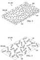
- FIGURE 2illustrates an embodiment of a sealing drape 201 that may include the sealing material 134 having absorbent particles 236 dispersed throughout the sealing drape 201.
- the absorbent particles 236may provide the previously described absorbent material 136.
- the absorbent particles 236may have any size or shape, depending on a variety of factors, such as the nature of the tissue site 102 or the amount of fluid anticipated to be released by the tissue site 102. In applications in which the tissue site 102 releases a large amount of fluid, larger absorbent particles 236 may be desirable to provide adequate absorptive capacity for the fluid.
- FIGURE 3illustrates another embodiment of a sealing drape 301 in which absorbent fibers 336, such as elongate tubes, are dispersed throughout the sealing material 134.
- the absorbent fibers 336may provide the previously described absorbent material 136.
- the absorbent fibers 336may have any size or shape, depending on a variety of factors including the amount of fluid anticipated to be released by the tissue site 102. This specification contemplates embodiments including a mixture of absorbent particles 236 and absorbent fibers 336 dispersed within the sealing material 134 as described herein.
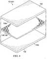
- FIGURE 4illustrates another embodiment of a sealing drape 401 in which the absorbent material 136 comprises an absorbent layer 436 positioned within the sealing material 134.
- the sealing drape 401may include a first layer 134a of the sealing material 134 and a second layer 134b of the sealing material 134.
- the absorbent layer 436may be positioned between the first layer 134a and the second layer 134b.
- the first layer 134a, the second layer 134b, and the absorbent layer 436may each have the same or a different thickness.
- the absorbent layer 436may be disposed at varying distances from the external surface 130 of the sealing drape 401 and the interior surface 132 of the sealing drape 401 depending on the thickness of each of the first and the second layer 134a, 134b.
- the absorbent layer 436may be provided as a nonwoven or a woven structure.
- the absorbent layer 436may comprise a nonwoven or a woven sheet of CMC fibers. Spaces or voids in the absorbent layer 436 may allow a reduced pressure that is applied to the reduced-pressure dressing 112 to be transferred within and through the absorbent layer 436.
- the absorbent layer 436may have any size, shape, or thickness, depending on a variety of factors, such as the type of treatment being implemented or the nature of the tissue site 102.
- the size and shape of the absorbent layer 436may be customized by a user to extend through a particular portion of the sealing drape 401.
- the absorbent layer 436may be designed to cover a particular portion of the tissue site 102 or nearby tissue.
- the width or thickness of the absorbent layer 436may be increased to cause a corresponding increase in fluid storage capacity of the absorbent layer 436.
- the absorbent particles 236 and/or the absorbent fibers 336may be dispersed or otherwise disposed throughout the sealing material 134 in a substantially uniform manner. A substantially uniform dispersion of the absorbent particles 236 and/or the absorbent fibers 336 may reduce the distance fluid must travel from the interior surface 132 before being absorbed. As described below, in some embodiments, utilizing a configuration for the sealing drape 101 that employs the absorbent particles 236 and/or the absorbent fibers 336 and/or the absorbent layer 436 may allow a user to customize the absorption gradient through the cross section of the sealing drape 101 for a desired application. Further, in some embodiments, the absorbent particles 236 and/or the absorbent fibers 336 may be dispersed or otherwise disposed within the sealing material 134 at a desired concentration and location within the sealing drape 101 to suit a particular application.
- FIGURE 5illustrates another embodiment of a sealing drape 501 that may have a plurality of the previously described absorbent materials 236, 336, 436 configured as described above with the sealing material 134.
- the absorbent materials 236, 336, 436may be configured with the sealing member 134 as described, and positioned in layers relative to one another within the sealing drape 501. Further, the absorbent materials 236, 336, 436 may have the same or different dimensions and include the same or different absorbent properties.
- the plurality of absorbent materials 236, 336, 436may increase in concentration with increasing distance from the interior surface 132 of the sealing drape 501 through the cross section of the sealing drape 501, such as, for example, from the interior surface 132 toward the external surface 130.
- the sealing drape 501may have a higher ratio of the absorbent material 236, 336, 436 to the sealing material 134 with increasing distance from the interior surface 132.
- the absorbent materials 236, 336, 436may exhibit increasing hydrophilicity or absorbency with increasing distance from the interior surface 132.
- the plurality of absorbent materials 236, 336, 436may be disposed within the sealing drape 501 such that the absorbent materials 236, 336, 436 positioned farthest from the interior surface 132 absorb more fluid than those closer to the interior surface 132.
- the absorbent layer 436 positioned furthest away from the interior surface 132may have a higher fluid storage capacity than the absorbent materials 336, 236 positioned successively closer to the interior surface 132.
- the plurality of absorbent materials 236, 336, 436may provide a 3-dimensional network of absorbent material to enhance the transfer of moisture away from the tissue site 102 and to retain the moisture at a maximum distance away from the tissue site 102.
- This configurationmay be customized as described to provide a desired absorptive gradient, Moisture Vapor Transmission Rate (MVTR), and fluid storage capacity to suit a particular application.
- MVTRMoisture Vapor Transmission Rate
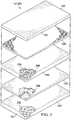
- FIGURE 6illustrates another embodiment of a sealing drape 601 that may include the absorbent material 136 carried by a carrier 635.
- the carrier 635 including the absorbent material 136may be positioned within the sealing material 134.
- the sealing drape 601may include the first layer 134a and the second layer 134b of the sealing material 134.
- the carrier 635may be positioned as a layer between the first layer 134a and the second layer 134b.
- the carrier 635may provide a support structure that carries the absorbent material 136.
- the carrier 635may comprise any of a variety of shapes and sizes, and may comprise any suitable nonwoven or woven material.
- the carrier 635may comprise a nonwoven hydrophobic polypropylene material that is formed into a sheet-like structure.
- the carrier 635may provide support and strength for the absorbent material 136.
- the absorbent material 136may be dispersed within the carrier 635 as absorbent particles 236 and/or absorbent fibers 336.
- the sealing drape 101, 201, 301, 401, 501, and 601may be self-sealing to the tissue site 102, or may require an additional sealing device.
- the sealing material 134 of the sealing drape 101, 201, 301, 401, 501, and 601may comprise a hydrophobic silicone elastomer, which may function as a silicone adhesive and form a direct bond with the peripheral surface 128 of the tissue site 102, the epidermis 106, or the manifold 118.
- the reduced-pressure dressing 112may include an additional attachment device (not shown) to fluidly seal the sealing drape 101, 201, 301, 401, 501, and 601 around the tissue site 102.
- the attachment devicemay be affixed to the interior surface 132 of the sealing drape 101, 201, 301, 401, 501, and 601 and may fluidly seal the sealing drape 101, 201, 301, 401, 501, and 601 to the epidermis 106 to provide the sealed space 123 surrounding the tissue site 102.
- the attachment devicemay cover at least a portion of the interior surface 132 of the sealing drape 101, 201, 301, 401, 501, and 601.
- Attachment devicesmay include, without limitation, a medically acceptable, pressure-sensitive adhesive that extends about a periphery, a portion of, or the entire sealing drape 101, 201, 301, 401, 501, and 601, a double-sided drape tape, paste, hydrocolloid, hydrogel, or similar sealing device.
- the sealing drape 101, 201, 301, 401, 501, and 601may be adapted to adhere to the peripheral surface 128 to secure the reduced-pressure dressing 112 to the tissue site 102.
- the reduced-pressure treatment system 100may be applied to a patient in the operating room after a surgical procedure or elsewhere.
- the manifold 118may be placed proximate to, within, overlying, or in contact with the tissue site 102.
- the sealing drape 101, 201, 301, 401, 501, and 601may be placed over or otherwise covering the manifold 118 such that a portion of the sealing drape 101, 201, 301, 401, 501, and 601 overlays the peripheral surface 128 around the tissue site 102.
- the sealing drape 101, 201, 301, 401, 501, and 601may be secured to the peripheral surface 128 in order to form a fluid seal between the tissue site 102 and the sealing drape 101, 201, 301, 401, 501, and 601.
- the fluid sealneed only be adequate to allow the reduced-pressure treatment system 100 to maintain a reduced pressure on the tissue site 102 for a desired treatment time.
- the individual components of the reduced-pressure dressing 112may be sized according to the particular application or the procedure being performed by a healthcare provider.
- the components of the reduced-pressure dressing 112may be sized, shaped, and configured to work in different anatomical applications such as the abdomen, chest, thighs, hip, and other locations.
- the reduced-pressure interface 122may be fluidly coupled to the sealing drape 101, 201, 301, 401, 501, and 601 before or after the installation of the sealing drape 101, 201, 301, 401, 501, and 601.
- the reduced-pressure conduit 116maybe fluidly coupled to the reduced-pressure interface 122.
- the reduced-pressure interface 122may also be omitted and the reduced-pressure conduit 116 may be directly inserted into the sealing drape 101, 201, 301, 401, 501, and 601 in fluid communication with the sealed space 123.
- the reduced-pressure conduit 116may be fluidly coupled to the reduced-pressure source 114.
- the reduced-pressure source 114may be activated to deliver reduced pressure to the sealed space 123 provided by the sealing drape 101, 201, 301, 401, 501, and 601 surrounding the tissue site 102.
- the reduced-pressure source 114may be a micro-pump in or on the reduced-pressure dressing 112.
- exudates or other fluids from the tissue site 102may be drawn into the manifold 118, the sealing drape 101, 201, 301, 401, 501, and 601, and through the reduced-pressure interface 122.
- the peripheral surface 128 as well the components of the reduced-pressure dressing 112may become moist, including the interior surface 132 of the sealing drape 101, 201, 301, 401, 501, and 601 where the sealing drape 101, 201, 301, 401, 501, and 601 contacts the peripheral surface 128 around the tissue site 102.
- the sealing drape 101, 201, 301, 401, 501, and 601may maintain a fluid seal with the tissue site 102.
- the sealing drape 101, 201, 301, 401, 501, and 601may allow fluid to pass through the interior surface 132 of the sealing drape 101, 201, 301, 401, 501, and 601 to reach the absorbent material 136 contained within the sealing material 134 of the sealing drape 101, 201, 301, 401, 501, and 601, thus helping to prevent saturation of the tissue site 102 and possible maceration.
- This specificationalso provides methods of manufacturing the sealing drape 101, 201, 301, 401, 501, and 601 for use with the reduced-pressure treatment system 100.
- the methodmay include the steps of providing the sealing material 134, and disposing the absorbent material 136 within the sealing material 134.
- the absorbent material 136may be the previously described absorbent particles 236, the absorbent fibers 336, the absorbent layer 436, or any combination thereof.
- the methodmay include the step of mixing the absorbent particles 236 and/or the absorbent fibers 336 within the sealing material 134 prior to curing or otherwise solidifying the sealing material 134.
- the methodmay further include the steps of forming the mixture of the absorbent particles 236 and/or the absorbent fibers 336 into a desired shape, such as a sheet, and curing or otherwise solidifying the mixture.
- the absorbent particles 236 and/or the absorbent fibers 336may be mixed within the sealing material 134 to provide a substantially uniform dispersion of the absorbent particles 236 and/or the absorbent fibers 336 within the sealing material 134.
- the absorbent particles 236 and/or the absorbent fibers 336may be mixed within the sealing material 134 to provide a desired concentration of the absorbent particles 236 and/or the absorbent fibers 336 within the sealing material 134 at desired location therein.
- the methodmay include the steps of providing the first layer 134a of the sealing material 134 and providing the second layer 134b of the sealing material 134.
- the methodmay additionally include the steps of providing the absorbent layer 436, positioning the absorbent layer 436 between the first and the second layer 134a, 134b, and enclosing the first and the second layer 134a, 134b about the absorbent layer 436.
- multiple layers of the sealing material 134 and the absorbent layers 436may be utilized to suit a particular application.
- the methodmay include the step of carrying the absorbent material 136, such as the absorbent particles 236 and/or the absorbent fibers 336, with the carrier 635.
- the absorbent particles 236 and/or the absorbent fibers 336may be applied to the carrier 635 for support and retention by the previously described non-woven or woven structure of the carrier 635.
- the methodmay additionally include the steps of providing the first layer 134a of the sealing material 134, and providing the second layer 134b of the sealing material 134.
- the methodmay include the steps of positioning the carrier 635, including the absorbent material 136, between the first and the second layer 134a, 134b, and enclosing the first and the second layer 134a, 134b about the carrier 635.
- multiple layers of the sealing material 134 and the carrier 635, including the absorbent material 136may be utilized to suit a particular application.
Landscapes
- Health & Medical Sciences (AREA)
- Heart & Thoracic Surgery (AREA)
- Animal Behavior & Ethology (AREA)
- Biomedical Technology (AREA)
- Vascular Medicine (AREA)
- Life Sciences & Earth Sciences (AREA)
- Engineering & Computer Science (AREA)
- General Health & Medical Sciences (AREA)
- Public Health (AREA)
- Veterinary Medicine (AREA)
- Anesthesiology (AREA)
- Hematology (AREA)
- Media Introduction/Drainage Providing Device (AREA)
- Materials For Medical Uses (AREA)
- Surgical Instruments (AREA)
Description
- The following subject matter relates generally to tissue treatment systems and, more particularly, but not by way of limitation, to medical sealing drapes and systems including medical sealing drapes.
- Known tissue treatment systems may use a sealing drape to provide a fluid seal about a tissue site requiring treatment. Sealing around particular anatomical areas of the tissue site can be complicated and a leak-free seal is often difficult to achieve and maintain. Typical sealing drape materials may lack a sufficiently conformable adhesive capable of flowing into creases and cracks around the tissue site to achieve a good seal. Current materials may also suffer from being unable to transfer moisture away from the tissue site. Thus, if the sealing drape remains in place for an extended period of time, moisture present near the tissue site can cause maceration of the tissue and the formation of leaks between the tissue site and the sealing drape. Accordingly, improvements to sealing and moisture transfer capabilities for sealing drapes are desirable.
WO2009/146441 describes a super-absorbent dressing assembly for use with a reduced-pressure wound treatment system, comprising a breathable, fluid restricted dry layer for placement against a wound, a super- absorbent layer, and a non-breathable layer, and a drape extending over the non-breathable layer.- Shortcomings with certain aspects of known tissue treatment systems and methods utilizing sealing drapes are addressed as shown and described in a variety of illustrative, non-limiting embodiments herein. Other features and advantages of the illustrative embodiments will become apparent with reference to the drawings and detailed description that follow.
- There is provided a sealing drape for treating a tissue site, the sealing drape comprising: an interior surface and an external surface, the interior surface for positioning adjacent a peripheral surface surrounding the tissue site and to overlap the peripheral surface to provide a sealed space between the sealing drape and the tissue site; a sealing material, the sealing material comprising a fluid permeable hydrophobic material free of hydrophilic components; an absorbent material disposed in the sealing material, the sealing material being positioned between the interior surface of the sealing drape and the absorbent material, the absorbent material for absorbing fluid communicated through the sealing material; and a plurality of absorbent materials disposed in the sealing material of the sealing drape, the absorbent materials having an absorptive capacity that increases with increasing distance through a cross section of the sealing drape from the interior surface of the sealing drape.
- A selection of optional features is set out in the dependent claims.
- A more complete understanding of this specification may be obtained by reference to the following detailed description when taken in conjunction with the accompanying drawings wherein:
FIGURE 1 is a side view, with a portion shown in cross section, of an illustrative embodiment of a reduced-pressure treatment system depicting an illustrative embodiment of a sealing drape;FIGURE 2 is a perspective view of another illustrative embodiment of a sealing drape suitable for use with the reduced-pressure treatment system ofFIGURE 1 ;FIGURE 3 is a perspective view of another illustrative embodiment of a sealing drape suitable for use with the reduced-pressure treatment system ofFIGURE 1 ;FIGURE 4 is a perspective, exploded view of another illustrative embodiment of a sealing drape suitable for use with the reduced-pressure treatment system ofFIGURE 1 ;FIGURE 5 is a perspective, exploded view of another illustrative embodiment of a sealing drape suitable for use with the reduced-pressure treatment system ofFIGURE 1 ; andFIGURE 6 is a perspective, exploded view of another illustrative embodiment of a sealing drape suitable for use with the reduced-pressure treatment system ofFIGURE 1 .- In the following detailed description of the illustrative, non-limiting embodiments, reference is made to the accompanying drawings that form a part hereof. Other embodiments may be utilized, and logical, structural, mechanical, electrical, and chemical changes may be made without departing from the scope of this specification. To avoid detail not necessary to enable those skilled in the art to practice the embodiments described herein, the detailed description may omit certain information known to those skilled in the art. The following detailed description is provided without limitation, and with the scope of the illustrative embodiments being defined by the appended claims.
- Referring generally to the drawings, this specification provides a reduced-
pressure treatment system 100 utilizing asealing drape 101 for treating atissue site 102. The reduced-pressure treatment system 100 is presented in the context of atissue site 102 that may include, without limitation, awound 104 extending through theepidermis 106, thedermis 108, and reaching into a hypodermis, orsubcutaneous tissue 110. The reduced-pressure treatment system 100 may include a reduced-pressure dressing 112, a reduced-pressure source 114, and a reduced-pressure delivery conduit 116. The reduced-pressure delivery conduit 116 may provide reduced pressure from the reduced-pressure source 114 to the reduced-pressure dressing 112. As will be described below, thesealing drape 101 may be a component of the reduced-pressure dressing 112 that will provide a fluid seal with thetissue site 102 while preventing the surface of thetissue site 102 from becoming saturated with moisture. - The term "tissue site" in this context, for example, may refer to a wound or defect located on or within any tissue, including but not limited to, bone tissue, adipose tissue, muscle tissue, neural tissue, dermal tissue, vascular tissue, connective tissue, cartilage, tendons, or ligaments. A wound may include, without limitation, any irregularity with a tissue, such as an open wound, surgical incision, or diseased tissue. For example, the wound may include chronic, acute, traumatic, subacute, and dehisced wounds, partial-thickness burns, ulcers (such as diabetic, pressure, or venous insufficiency ulcers), flaps, and grafts. The term "tissue site" may also refer to areas of any tissue that are not necessarily wounded or defective, but are instead areas in which it is desired to add or promote the growth of additional tissue. For example, reduced pressure may be used in certain tissue areas to grow additional tissue that may be harvested and transplanted to another location.
- In general, components of the reduced-
pressure treatment system 100 may be coupled directly or indirectly. For example, the reduced-pressure source 114 may be directly coupled to the reduced-pressure dressing 112 or indirectly coupled to the reduced-pressure dressing 112 through the reduced-pressure delivery conduit 116. Components may be fluidly coupled to each other to provide a path for transferring fluids, such as liquid or gas, between the components. In some embodiments, components may be fluidly coupled with a tube. A "tube," as used herein, may refer to any tube, pipe, hose, conduit, or other structure with one or more lumina adapted to convey fluids between two ends. In some embodiments, components may be coupled by virtue of physical proximity, being integral to a single structure, or being formed from the same piece of material. Coupling may also include mechanical, thermal, electrical, or chemical coupling, such as a chemical bond. - "Reduced pressure" may refer to a pressure less than the ambient pressure at a tissue site being subjected to treatment. The reduced pressure may be less than the atmospheric pressure. The reduced pressure may also be less than a hydrostatic pressure at a tissue site. Unless otherwise indicated, values of pressure stated herein are gauge pressures. Consistent with the use herein, an increase in reduced pressure or vacuum pressure may refer to a relative reduction in absolute pressure.
- The reduced-
pressure source 114 may provide reduced pressure as a part of the reduced-pressure treatment system 100. The reduced-pressure source 114 may be any device for supplying a reduced pressure, such as a vacuum pump, wall suction, micro-pump, or other source. While the amount and nature of reduced pressure applied to a tissue site may vary according to the treatment application, the reduced pressure may be between about -5 mm Hg (-667 Pa) to about -500 mm Hg (-66.7 kPa). In some embodiments, the reduced pressure may be between about -75 mm Hg (-9.9 kPa) to about -300 mm Hg (-39.9 kPa). - As shown in
FIGURE 1 , in some embodiments, the reduced-pressure dressing 112 may include amanifold 118, thesealing drape 101, and a reduced-pressure interface 122. Themanifold 118 may have afirst side 119 and asecond side 121. Thefirst side 119 of themanifold 118 may be placed within, over, proximate, adjacent, or in direct contact with thetissue site 102. - The
manifold 118 maybe a substance or structure capable of applying reduced pressure to, delivering fluids to, or removing fluids from thetissue site 102. Themanifold 118 may be positioned between thesealing drape 101 and thetissue site 102. Themanifold 118 may be partially or fully in contact with thetissue site 102. Themanifold 118 may partially or completely fill thetissue site 102, or themanifold 118 may be placed over thetissue site 102. Themanifold 118 may take many forms, and may be any size, shape, or thickness depending on a variety of factors, such as the type of treatment being implemented or the nature and size of a particular tissue site. For example, the size and shape of themanifold 118 may be adapted to the contours of deep and irregular shaped tissue sites. - The
manifold 118 may include a plurality of flow channels or pathways configured to distribute fluids to and remove fluids from thetissue site 102. In some embodiments, the flow channels or pathways may be interconnected to improve distribution of fluids provided to or removed from thetissue site 102. The manifold 118 may be a biocompatible material that is capable of being placed in contact with thetissue site 102 and distributing reduced pressure to thetissue site 102. For example, the manifold 118 may include, without limitation, devices that have structural elements arranged to form flow channels, such as cellular foam, open-cell foam, porous tissue collections, liquids, gels, and foams that include, or cure to include, flow channels. Additionally, the manifold 118 may be a gauze, felted mat, or any other material suited to a particular biological application. - In some embodiments, the manifold 118 may be a porous foam having interconnected cells or pores that act as flow channels. The porous foam may be, for example, a hydrophobic material, such as a polyurethane, open-cell reticulated foam manufactured under the trade name GranuFoam® by Kinetic Concepts, Inc. of San Antonio, Texas. In some embodiments, the manifold 118 may also be used to distribute fluids such as medications, antibacterials, growth factors, and various solutions to the
tissue site 102. Other layers may be included in or on the manifold 118, such as absorptive materials, wicking materials, hydrophobic materials, and hydrophilic materials. - In some embodiments, the manifold 118 may be made from a hydrophilic material capable of wicking fluid away from the
tissue site 102 while continuing to distribute reduced pressure to thetissue site 102. The wicking properties of the manifold 118 may draw fluid away from thetissue site 102 by capillary flow or other wicking mechanisms. An example of a hydrophilic foam may be a polyvinyl alcohol, open-cell foam such as V.A.C. WhiteFoam® dressing available from Kinetic Concepts, Inc. of San Antonio, Texas. Other hydrophilic foams may include those made from polyether. Other foams that may exhibit hydrophilic characteristics may include hydrophobic foams that have been treated or coated to provide hydrophilicity. - The manifold 118 may promote granulation at a tissue site when reduced-pressure is present within the reduced-
pressure dressing 112. For example, any or all of the surfaces of the manifold 118 may have an uneven, coarse, or jagged profile that induce microstrains and stresses at thetissue site 102 when reduced pressure is applied through themanifold 118. - In some embodiments, the manifold 118 may be constructed from a bioresorbable material that may remain in a patient's body following use of the reduced-
pressure dressing 112. Suitable bioresorbable materials may include, without limitation, a polymeric blend of polylactic acid (PLA) and polyglycolic acid (PGA). The polymeric blend may also include, without limitation, polycarbonates, polyfumarates, and capralactones. The manifold 118 may further serve as a scaffold for new cell-growth, or a scaffold material may be used in conjunction with the manifold 118 to promote cell-growth. A scaffold may be a substance or structure used to enhance or promote the growth of cells or formation of tissue, such as a three-dimensional porous structure that provides a template for cell growth. Illustrative examples of scaffold materials may include calcium phosphate, collagen, PLA/PGA, coral hydroxy apatites, carbonates, or processed allograft materials. - The sealing
drape 101 may be adapted to cover thesecond side 121 of the manifold 118 and to seal to aperipheral surface 128 proximate thetissue site 102. Thus, the sealingdrape 101 may provide a fluid seal between the reduced-pressure dressing 112 and thetissue site 102. "Fluid seal," or "seal," may refer to a seal adequate to maintain reduced pressure at a desired tissue site given the particular reduced-pressure source involved. - The
peripheral surface 128 may beundamaged epidermis 106 peripheral to thetissue site 102. Thus, the sealingdrape 101 may provide a sealedspace 123 proximate to thetissue site 102 that is substantially isolated from the external environment, and capable of maintaining a reduced pressure provided by the reduced-pressure source 114. Reduced pressure applied through the manifold 118 in the sealedspace 123 can promote healing by inducing macrostrain and microstrain in thetissue site 102, as well as by removing exudates and other fluids from thetissue site 102. Fluids from thetissue site 102 may be collected for disposal by a fluid canister (not shown) associated with the reduced-pressure source 114. - The sealing
drape 101 may comprise an elastomeric material. "Elastomeric" may refer to the properties of an elastomer, such as a polymeric material that has rubber-like properties. More specifically, some elastomers have elongation rates greater than 100% and a significant amount of resilience. The resilience of a material may refer to the ability of the material to recover from an elastic deformation. - In some embodiments, the reduced-pressure dressing 112 may also include additional layers (not shown) positioned between the
tissue site 102 and the sealingdrape 101. For example, the reduced-pressure dressing 112 may further include an absorption layer, tissue-interface layer, or additional manifold layers. The reduced-pressure dressing 112 may also include an attachment device (not shown) capable of adhering or otherwise sealing the sealingdrape 101 to theperipheral surface 128. Materials suitable for use as attachment devices for adhering the sealingdrape 101 about a tissue site, may include, for example, silicones and hot-melt adhesives. Other attachment devices may include, for example, hydrogels and hydrocolloids. - Reduced pressure may be applied to the reduced-pressure dressing 112 through the reduced-
pressure interface 122. The reduced-pressure interface 122 may be fluidly coupled to the sealingdrape 101 through anaperture 124 in the sealingdrape 101. In the illustrative example ofFIGURE 1 , theaperture 124 is shown centrally located on the sealingdrape 101. However, theaperture 124 may be located anywhere on the sealingdrape 101, including without limitation, a peripheral portion of the sealingdrape 101 that may be adjacent to an edge of the sealingdrape 101. Although theaperture 124 is shown to be circular, theaperture 124 may have any shape. The shape of theaperture 124 may also be adapted to contour or substantially coordinate with the shape of the reduced-pressure delivery conduit 116. The reduced-pressure interface 122 may provide fluid communication between the sealedspace 123 and the reduced-pressure delivery conduit 116 through theaperture 124. - The reduced pressure provided by the reduced-
pressure source 114 may be delivered through the reduced-pressure delivery conduit 116 to the reduced-pressure interface 122. Thus, the reduced-pressure source 114 may be fluidly coupled to the reduced-pressure interface 122 by the reduced-pressure delivery conduit 116. In some embodiments, the reduced-pressure interface 122 may be a T.R.A.C.® Pad or Sensa T.R.A.C.® Pad available from Kinetic Concepts, Inc. of San Antonio, Texas. The reduced-pressure interface 122 may allow the reduced pressure to be delivered to the sealingdrape 101 and realized within the sealedspace 123 formed between the sealingdrape 101 and thetissue site 102. In some embodiments, the reduced-pressure interface 122 may extend through the sealingdrape 101 to the manifold 118, but numerous arrangements are possible. The reduced-pressure interface 122 may deliver the reduced pressure through theaperture 124 of the sealingdrape 101 to the manifold 118 and thetissue site 102. - Upon application of the reduced pressure to the reduced-pressure dressing 112, fluids such as exudates from the
tissue site 102 may be drawn into themanifold 118. Some amount of fluid as a consequence may also be brought into contact with the sealingdrape 101, including portions of the sealingdrape 101 that may be adjacent theperipheral surface 128 surrounding thetissue site 102. Moisture at the interface between theperipheral surface 128 and the sealingdrape 101 may adversely affect the seal between the sealingdrape 101 and theperipheral surface 128, and may increase the risk of maceration. "Maceration" or "macerating" may refer to the softening or breaking down of tissue as a result of prolonged exposure to moisture. - The sealing
drape 101 of the reduced-pressure treatment system 100 can overcome these shortcomings and others by maintaining a fluid seal with thetissue site 102, while also preventing theperipheral surface 128 from becoming saturated with moisture. The sealingdrape 101 may adhere to thetissue site 102 when wet or dry, may transmit and manage low levels of skin moisture to avoid maceration, and may be left in place for extended time periods. - Continuing with the embodiment of
FIGURE 1 , the sealingdrape 101 may have anexternal surface 130 and aninterior surface 132. Theinterior surface 132 may be adapted to face thetissue site 102. As previously described, the sealingdrape 101 may be adapted to sealingly engage theperipheral surface 128 to provide a sealedspace 123 with thetissue site 102. Theinterior surface 132 of the sealingdrape 101 may contact theperipheral surface 128 surrounding thetissue site 102 to provide the sealedspace 123. The sealingdrape 101 may also be stretchable or elastic in nature. The stretchable properties of the sealingdrape 101 may facilitate placement of the sealingdrape 101 proximate to tissue sites having a variety of shapes, topologies, or flexibility requirements. The sealingdrape 101 may be sized to extend beyond thetissue site 102 to overlap theperipheral surface 128 surrounding thetissue site 102. - The sealing
drape 101 may include a sealingmaterial 134 and anabsorbent material 136. The sealingmaterial 134 may be fluid permeable, may provide a substantially sheet-like structure for the sealingdrape 101, and may form a part of theinterior surface 132 of the sealingdrape 101. Theabsorbent material 136 may, for example, be contained within the sealingmaterial 134, dispersed throughout the sealingmaterial 134, or embedded as a sheet-like layer within the sealingmaterial 134. Theabsorbent material 136 may be adapted to absorb moisture, such as exudate, from thetissue site 102 by drawing or wicking the fluid from theperipheral surface 128 of thetissue site 102. - The sealing
material 134 may be comprised of any substantially pure hydrophobic material, and may have a variety of structures, including materials and structures that allow fluid, such as liquid or gas, to pass through the sealingmaterial 134 without being absorbed by the sealingmaterial 134. Herein, a substantially pure hydrophobic material may be substantially free of hydrophilic components due to the tendency for hydrophilic materials to retain fluid. For example, the substantially pure hydrophobic material of the sealingmaterial 134 may not be a copolymer incorporating a hydrophilic component, such as a hydrophilic monomer. The sealingmaterial 134, for example, may comprise a hydrophobic elastomer, such as a hydrophobic silicone elastomer. The hydrophobic characteristics of the sealingmaterial 134 may prevent the sealingmaterial 134 from directly absorbing fluid, such as exudate, from thetissue site 102, but may allow the fluid to pass through. Thus, the sealingmaterial 134 may permit the passage of fluid away from theperipheral surface 128 and thetissue site 102 to substantially preclude any adverse affect on the seal being maintained with thetissue site 102. In this manner, the sealingmaterial 134 may enhance the management of fluid in the reduced-pressure dressing 112 to allow for a continued fluid seal with thetissue site 102, while also protecting thetissue site 102 and surrounding areas from maceration. - The
absorbent material 136 may be a hydrophilic material capable of absorbing fluid. Theabsorbent material 136 may be a separate and distinct component coupled with the sealingmaterial 134 as described herein to provide the sealingdrape 101. In some embodiments, theabsorbent material 136 may comprise a super-absorbent material. For example, theabsorbent material 136 may comprise one or more super-absorbent materials, such as, for example, carboxymethyl cellulose (CMC) or a carboxymethylcellulose salt, a cross-linked hydrophilic acrylic or a cross-linked hydrophilic acrylic salt, or an acrylamide. - When coupled with the sealing
material 134, theabsorbent material 136 may provide an absorption gradient to draw or otherwise wick fluid away from thetissue site 102. Fluid from thetissue site 102 may be drawn by the absorption gradient through the sealingmaterial 134 and then be absorbed by theabsorbent material 136. Theabsorbent material 136 may retain or bond to the fluid in conjunction with a physical or chemical change to theabsorbent material 136. Theabsorbent material 136 may, for example, gel, increase in viscosity, or otherwise thicken upon contact with fluid from thetissue site 102, thereby trapping the fluid. The wicking properties of theabsorbent material 136 may quickly draw fluid away from thetissue site 102, and thus, may prevent the accumulation of fluid at or near thetissue site 102. In a similar manner, the sealingmaterial 134 may facilitate the evaporation of fluid absorbed by theabsorbent material 136 or otherwise transferred through the sealingmaterial 134 towards theexternal surface 130 of the sealingdrape 101. Since fluid from thetissue site 102 may pass through the sealingmaterial 134 to reach theabsorbent material 136 as described above, the sealingmaterial 134 may provide a separation between thetissue site 102 and theabsorbent material 136. Thus, the sealingmaterial 134 may be positioned between theinterior surface 132 of the sealingdrape 101 and theabsorbent material 136. Further, the sealingmaterial 134 may substantially preclude fluid that has been absorbed by theabsorbent material 136 from contacting thetissue site 102 and theperipheral surface 128. - The sealing
material 134 may have any size, shape, or thickness depending on a variety of factors, such as the type of treatment being implemented, the nature of thetissue site 102, or theperipheral surface 128. The thickness of the sealingmaterial 134 may be increased or decreased to optimize the effectiveness of the sealingmaterial 134 as a separator between thetissue site 102 and theabsorbent material 136. For example, in applications in which thetissue site 102 is expected to release a large amount of fluid, athicker sealing material 134 may be desirable to restrain or prevent the fluid from contacting thetissue site 102 or theperipheral surface 128. Conversely, athinner sealing material 134 may be desirable in applications in which a lower amount of fluid is present. For example, the sealingmaterial 134 may be between about 100 micrometers to about 200 micrometers in thickness. The thickness of the sealingmaterial 134 may also be adjusted according to a desired ratio of the sealingmaterial 134 to theabsorbent material 136 comprising the sealingdrape 101 depending on the application. In some embodiments, the overall thickness of the sealingdrape 101 including the sealingmaterial 134 and theabsorbent material 136 may be about 250 micrometers. - The
absorbent material 136 may be dispersed throughout and/or embedded as a sheet-like layer within the sealingmaterial 134.FIGURE 2 illustrates an embodiment of a sealing drape 201 that may include the sealingmaterial 134 havingabsorbent particles 236 dispersed throughout the sealing drape 201. Theabsorbent particles 236 may provide the previously describedabsorbent material 136. Theabsorbent particles 236 may have any size or shape, depending on a variety of factors, such as the nature of thetissue site 102 or the amount of fluid anticipated to be released by thetissue site 102. In applications in which thetissue site 102 releases a large amount of fluid, largerabsorbent particles 236 may be desirable to provide adequate absorptive capacity for the fluid. FIGURE 3 illustrates another embodiment of a sealing drape 301 in whichabsorbent fibers 336, such as elongate tubes, are dispersed throughout the sealingmaterial 134. Theabsorbent fibers 336 may provide the previously describedabsorbent material 136. Theabsorbent fibers 336 may have any size or shape, depending on a variety of factors including the amount of fluid anticipated to be released by thetissue site 102. This specification contemplates embodiments including a mixture ofabsorbent particles 236 andabsorbent fibers 336 dispersed within the sealingmaterial 134 as described herein.FIGURE 4 illustrates another embodiment of a sealing drape 401 in which theabsorbent material 136 comprises anabsorbent layer 436 positioned within the sealingmaterial 134. The sealing drape 401 may include afirst layer 134a of the sealingmaterial 134 and asecond layer 134b of the sealingmaterial 134. Theabsorbent layer 436 may be positioned between thefirst layer 134a and thesecond layer 134b. Thefirst layer 134a, thesecond layer 134b, and theabsorbent layer 436 may each have the same or a different thickness. Thus, theabsorbent layer 436 may be disposed at varying distances from theexternal surface 130 of the sealing drape 401 and theinterior surface 132 of the sealing drape 401 depending on the thickness of each of the first and thesecond layer - The
absorbent layer 436 may be provided as a nonwoven or a woven structure. For example, theabsorbent layer 436 may comprise a nonwoven or a woven sheet of CMC fibers. Spaces or voids in theabsorbent layer 436 may allow a reduced pressure that is applied to the reduced-pressure dressing 112 to be transferred within and through theabsorbent layer 436. - Further, the
absorbent layer 436 may have any size, shape, or thickness, depending on a variety of factors, such as the type of treatment being implemented or the nature of thetissue site 102. The size and shape of theabsorbent layer 436 may be customized by a user to extend through a particular portion of the sealing drape 401. Thus, theabsorbent layer 436 may be designed to cover a particular portion of thetissue site 102 or nearby tissue. For example, the width or thickness of theabsorbent layer 436 may be increased to cause a corresponding increase in fluid storage capacity of theabsorbent layer 436. - Referring to
FIGURES 2-3 , in some embodiments, theabsorbent particles 236 and/or theabsorbent fibers 336 may be dispersed or otherwise disposed throughout the sealingmaterial 134 in a substantially uniform manner. A substantially uniform dispersion of theabsorbent particles 236 and/or theabsorbent fibers 336 may reduce the distance fluid must travel from theinterior surface 132 before being absorbed. As described below, in some embodiments, utilizing a configuration for the sealingdrape 101 that employs theabsorbent particles 236 and/or theabsorbent fibers 336 and/or theabsorbent layer 436 may allow a user to customize the absorption gradient through the cross section of the sealingdrape 101 for a desired application. Further, in some embodiments, theabsorbent particles 236 and/or theabsorbent fibers 336 may be dispersed or otherwise disposed within the sealingmaterial 134 at a desired concentration and location within the sealingdrape 101 to suit a particular application. FIGURE 5 illustrates another embodiment of a sealing drape 501 that may have a plurality of the previously describedabsorbent materials material 134. Theabsorbent materials member 134 as described, and positioned in layers relative to one another within the sealing drape 501. Further, theabsorbent materials absorbent materials interior surface 132 of the sealing drape 501 through the cross section of the sealing drape 501, such as, for example, from theinterior surface 132 toward theexternal surface 130. Similarly, the sealing drape 501 may have a higher ratio of theabsorbent material material 134 with increasing distance from theinterior surface 132. In some embodiments, theabsorbent materials interior surface 132. Further, in some embodiments, the plurality ofabsorbent materials absorbent materials interior surface 132 absorb more fluid than those closer to theinterior surface 132. For example, theabsorbent layer 436 positioned furthest away from theinterior surface 132, as shown inFIGURE 5 , may have a higher fluid storage capacity than theabsorbent materials interior surface 132. In this manner, the plurality ofabsorbent materials tissue site 102 and to retain the moisture at a maximum distance away from thetissue site 102. This configuration may be customized as described to provide a desired absorptive gradient, Moisture Vapor Transmission Rate (MVTR), and fluid storage capacity to suit a particular application.FIGURE 6 illustrates another embodiment of a sealing drape 601 that may include theabsorbent material 136 carried by acarrier 635. Thecarrier 635 including theabsorbent material 136 may be positioned within the sealingmaterial 134. For example, similar to the sealing drape 401, the sealing drape 601 may include thefirst layer 134a and thesecond layer 134b of the sealingmaterial 134. Thecarrier 635 may be positioned as a layer between thefirst layer 134a and thesecond layer 134b. Thus, thecarrier 635 may provide a support structure that carries theabsorbent material 136. Thecarrier 635 may comprise any of a variety of shapes and sizes, and may comprise any suitable nonwoven or woven material. In some embodiments, thecarrier 635 may comprise a nonwoven hydrophobic polypropylene material that is formed into a sheet-like structure. Thecarrier 635 may provide support and strength for theabsorbent material 136. In some embodiments, theabsorbent material 136 may be dispersed within thecarrier 635 asabsorbent particles 236 and/orabsorbent fibers 336.- The sealing
drape 101, 201, 301, 401, 501, and 601 may be self-sealing to thetissue site 102, or may require an additional sealing device. As discussed above, in one embodiment, the sealingmaterial 134 of the sealingdrape 101, 201, 301, 401, 501, and 601 may comprise a hydrophobic silicone elastomer, which may function as a silicone adhesive and form a direct bond with theperipheral surface 128 of thetissue site 102, theepidermis 106, or themanifold 118. - In some embodiments, the reduced-pressure dressing 112 may include an additional attachment device (not shown) to fluidly seal the sealing
drape 101, 201, 301, 401, 501, and 601 around thetissue site 102. The attachment device may be affixed to theinterior surface 132 of the sealingdrape 101, 201, 301, 401, 501, and 601 and may fluidly seal the sealingdrape 101, 201, 301, 401, 501, and 601 to theepidermis 106 to provide the sealedspace 123 surrounding thetissue site 102. The attachment device may cover at least a portion of theinterior surface 132 of the sealingdrape 101, 201, 301, 401, 501, and 601. Attachment devices may include, without limitation, a medically acceptable, pressure-sensitive adhesive that extends about a periphery, a portion of, or theentire sealing drape 101, 201, 301, 401, 501, and 601, a double-sided drape tape, paste, hydrocolloid, hydrogel, or similar sealing device. In this manner, the sealingdrape 101, 201, 301, 401, 501, and 601 may be adapted to adhere to theperipheral surface 128 to secure the reduced-pressure dressing 112 to thetissue site 102. - In an illustrative embodiment of operation, the reduced-
pressure treatment system 100 may be applied to a patient in the operating room after a surgical procedure or elsewhere. For example, the manifold 118 may be placed proximate to, within, overlying, or in contact with thetissue site 102. The sealingdrape 101, 201, 301, 401, 501, and 601 may be placed over or otherwise covering the manifold 118 such that a portion of the sealingdrape 101, 201, 301, 401, 501, and 601 overlays theperipheral surface 128 around thetissue site 102. The sealingdrape 101, 201, 301, 401, 501, and 601 may be secured to theperipheral surface 128 in order to form a fluid seal between thetissue site 102 and the sealingdrape 101, 201, 301, 401, 501, and 601. The fluid seal need only be adequate to allow the reduced-pressure treatment system 100 to maintain a reduced pressure on thetissue site 102 for a desired treatment time. The individual components of the reduced-pressure dressing 112 may be sized according to the particular application or the procedure being performed by a healthcare provider. For example, the components of the reduced-pressure dressing 112 may be sized, shaped, and configured to work in different anatomical applications such as the abdomen, chest, thighs, hip, and other locations. - The reduced-
pressure interface 122 may be fluidly coupled to the sealingdrape 101, 201, 301, 401, 501, and 601 before or after the installation of the sealingdrape 101, 201, 301, 401, 501, and 601. The reduced-pressure conduit 116 maybe fluidly coupled to the reduced-pressure interface 122. The reduced-pressure interface 122 may also be omitted and the reduced-pressure conduit 116 may be directly inserted into the sealingdrape 101, 201, 301, 401, 501, and 601 in fluid communication with the sealedspace 123. The reduced-pressure conduit 116 may be fluidly coupled to the reduced-pressure source 114. The reduced-pressure source 114 may be activated to deliver reduced pressure to the sealedspace 123 provided by the sealingdrape 101, 201, 301, 401, 501, and 601 surrounding thetissue site 102. In some embodiments, the reduced-pressure source 114 may be a micro-pump in or on the reduced-pressure dressing 112. - Upon application of the reduced pressure to the reduced-pressure dressing 112, exudates or other fluids from the
tissue site 102 may be drawn into the manifold 118, the sealingdrape 101, 201, 301, 401, 501, and 601, and through the reduced-pressure interface 122. As fluids are drawn from thetissue site 102, theperipheral surface 128 as well the components of the reduced-pressure dressing 112 may become moist, including theinterior surface 132 of the sealingdrape 101, 201, 301, 401, 501, and 601 where the sealingdrape 101, 201, 301, 401, 501, and 601 contacts theperipheral surface 128 around thetissue site 102. Because of the ability of the sealingdrape 101, 201, 301, 401, 501, and 601 to transfer moisture away from theperipheral surface 128 of thetissue site 102, the sealingdrape 101, 201, 301, 401, 501, and 601 may maintain a fluid seal with thetissue site 102. The sealingdrape 101, 201, 301, 401, 501, and 601 may allow fluid to pass through theinterior surface 132 of the sealingdrape 101, 201, 301, 401, 501, and 601 to reach theabsorbent material 136 contained within the sealingmaterial 134 of the sealingdrape 101, 201, 301, 401, 501, and 601, thus helping to prevent saturation of thetissue site 102 and possible maceration. - This specification also provides methods of manufacturing the sealing
drape 101, 201, 301, 401, 501, and 601 for use with the reduced-pressure treatment system 100. In some embodiments, the method may include the steps of providing the sealingmaterial 134, and disposing theabsorbent material 136 within the sealingmaterial 134. Theabsorbent material 136 may be the previously describedabsorbent particles 236, theabsorbent fibers 336, theabsorbent layer 436, or any combination thereof. - In embodiments utilizing the
absorbent particles 236 and theabsorbent fibers 336, such as the sealing drape 201, 301, the method may include the step of mixing theabsorbent particles 236 and/or theabsorbent fibers 336 within the sealingmaterial 134 prior to curing or otherwise solidifying the sealingmaterial 134. The method may further include the steps of forming the mixture of theabsorbent particles 236 and/or theabsorbent fibers 336 into a desired shape, such as a sheet, and curing or otherwise solidifying the mixture. In some embodiments, theabsorbent particles 236 and/or theabsorbent fibers 336 may be mixed within the sealingmaterial 134 to provide a substantially uniform dispersion of theabsorbent particles 236 and/or theabsorbent fibers 336 within the sealingmaterial 134. In some embodiments, theabsorbent particles 236 and/or theabsorbent fibers 336 may be mixed within the sealingmaterial 134 to provide a desired concentration of theabsorbent particles 236 and/or theabsorbent fibers 336 within the sealingmaterial 134 at desired location therein. - In embodiments utilizing the
absorbent layer 436, such as the sealing drape 401, the method may include the steps of providing thefirst layer 134a of the sealingmaterial 134 and providing thesecond layer 134b of the sealingmaterial 134. The method may additionally include the steps of providing theabsorbent layer 436, positioning theabsorbent layer 436 between the first and thesecond layer second layer absorbent layer 436. In other embodiments, multiple layers of the sealingmaterial 134 and theabsorbent layers 436 may be utilized to suit a particular application. - In embodiments utilizing the
carrier 635, such as the sealing drape 601, the method may include the step of carrying theabsorbent material 136, such as theabsorbent particles 236 and/or theabsorbent fibers 336, with thecarrier 635. For example, theabsorbent particles 236 and/or theabsorbent fibers 336 may be applied to thecarrier 635 for support and retention by the previously described non-woven or woven structure of thecarrier 635. The method may additionally include the steps of providing thefirst layer 134a of the sealingmaterial 134, and providing thesecond layer 134b of the sealingmaterial 134. Further, the method may include the steps of positioning thecarrier 635, including theabsorbent material 136, between the first and thesecond layer second layer carrier 635. In some embodiments, multiple layers of the sealingmaterial 134 and thecarrier 635, including theabsorbent material 136, may be utilized to suit a particular application. - Although the
treatment system 100 has been disclosed in the context of certain illustrative, non-limiting embodiments, various changes, substitutions, permutations, and alterations can be made without departing from the scope of this specification as defined by the appended claims. Any feature described in connection to any one embodiment may also be applicable to any other embodiment.
Claims (14)
- A sealing drape (101, 201, 301, 401, 501, 601) for treating a tissue site (102), the sealing drape (101, 201, 301, 401, 501, 601) comprising:an interior surface (132) and an external surface (130), the interior surface (132) for positioning adjacent a peripheral surface (128) surrounding the tissue site (102) and to overlap the peripheral surface (128) to provide a sealed space (123) between the sealing drape (101, 201, 301, 401, 501, 601) and the tissue site (102);a sealing material (134), the sealing material (134) comprising a fluid permeable hydrophobic material free of hydrophilic components;an absorbent material (136, 236, 336, 436) disposed in the sealing material (134), the sealing material (134) being positioned between the interior surface (132) of the sealing drape (101, 201, 301, 401, 501, 601) and the absorbent material (136, 236, 336, 436), the absorbent material (136, 236, 336, 436) for absorbing fluid communicated through the sealing material (134); anda plurality of absorbent materials (136, 236, 336, 436) disposed in the sealing material (134) of the sealing drape (101, 201, 301, 401, 501, 601), the absorbent materials (136, 236, 336, 436) having an absorptive capacity that increases with increasing distance through a cross section of the sealing drape (101, 201, 301, 401, 501, 601) from the interior surface (132) of the sealing drape (101, 201, 301, 401, 501, 601).
- The sealing drape (101, 201, 301, 401, 501, 601) of claim 1, the absorbent material (136, 236, 336, 436) disposed uniformly within the sealing material (134).
- The sealing drape (101, 201, 301, 401, 501, 601) of claim 1, the absorbent material (136, 236, 336, 436) comprising a plurality of absorbent particles (236) or a plurality of absorbent fibers (336).
- The sealing drape (101, 201, 301, 401, 501, 601) of claim 1, the absorbent material (136, 236, 336, 436) comprising a sheet-like absorbent layer (436) disposed between a first layer (134a) and a second layer (134b) of the sealing material (134).
- The sealing drape (101, 201, 301, 401, 501, 601) of claim 1, the absorbent material (136, 236, 336, 436) for providing an absorptive gradient through the sealing drape (101, 201, 301, 401, 501, 601).
- The sealing drape (101, 201, 301, 401, 501, 601) of claim 1, further comprising a carrier (635) that carries the absorbent material (136, 236, 336, 436), the carrier (635) and the absorbent material (136, 236, 336, 436) being disposed between a first layer (134a) and a second layer (134b) of the sealing material (134).
- The sealing drape of claim 6, the carrier (635) comprising a hydrophobic polypropylene sheet.
- The sealing drape of claim 1, wherein the absorbent material (136, 236, 336, 436) comprises a three-dimensional structure of interconnected absorbent fibers (336), absorbent particles (236), and sheet-like absorbent layers (436).
- The sealing drape of claim 1, wherein the sealing material (134) comprises an elastomeric material or a hydrophobic silicone elastomer.
- The sealing drape (101, 201, 301, 401, 501, 601) of claim 1, wherein the sealing material (134) of the sealing drape (101, 201, 301, 401, 501, 601) is for providing evaporation of fluid retained in the absorbent material (136, 236, 336, 436) through the external surface of the sealing drape (101, 201, 301, 401, 501, 601).
- A reduced-pressure system (100) for treating a tissue site (102), the system (100) comprising:a manifold (118) for positioning adjacent the tissue site (102) and to distribute reduced pressure to the tissue site (102);a sealing drape according to any of claims 1 to 10; anda reduced-pressure interface (122) for delivering reduced-pressure, the reduced-pressure interface (122) in fluid communication with the sealed space (123) and the manifold (118).
- The system of claim 11, further comprising a reduce-pressure source (114) in fluid communication with the reduced-pressure interface (122).
- A method of manufacturing a sealing drape (101, 201, 301, 401, 501, 601) according to any of claims 1 to 10 for treating a tissue site (102), the method comprising:providing a sealing material (134) being hydrophobic and free of hydrophilic components;providing an absorbent material (136, 236, 336, 436); anddisposing the absorbent material (136, 236, 336, 436) in the sealing material.
- The method of claim 13, the step of disposing the absorbent material (136, 236, 336, 436) in the sealing material (134) comprises:mixing the absorbent material (136, 236, 336, 436) and the sealing material (134) together to provide a uniform dispersion of absorbent material (136, 236, 336, 436) within the sealing material (134); andcuring the mixture.
Priority Applications (2)
| Application Number | Priority Date | Filing Date | Title |
|---|---|---|---|
| EP16173790.3AEP3081199B1 (en) | 2013-01-03 | 2013-12-12 | Moisture absorbing seal |
| EP19205294.2AEP3616661A1 (en) | 2013-01-03 | 2013-12-12 | Moisture absorbing seal |
Applications Claiming Priority (2)
| Application Number | Priority Date | Filing Date | Title |
|---|---|---|---|
| US201361748711P | 2013-01-03 | 2013-01-03 | |
| PCT/US2013/074763WO2014107281A1 (en) | 2013-01-03 | 2013-12-12 | Moisture absorbing seal |
Related Child Applications (3)
| Application Number | Title | Priority Date | Filing Date |
|---|---|---|---|
| EP19205294.2ADivisionEP3616661A1 (en) | 2013-01-03 | 2013-12-12 | Moisture absorbing seal |
| EP16173790.3ADivision-IntoEP3081199B1 (en) | 2013-01-03 | 2013-12-12 | Moisture absorbing seal |
| EP16173790.3ADivisionEP3081199B1 (en) | 2013-01-03 | 2013-12-12 | Moisture absorbing seal |
Publications (3)
| Publication Number | Publication Date |
|---|---|
| EP2941232A1 EP2941232A1 (en) | 2015-11-11 |
| EP2941232B1 EP2941232B1 (en) | 2016-07-20 |
| EP2941232B2true EP2941232B2 (en) | 2019-04-10 |
Family
ID=49881139
Family Applications (3)
| Application Number | Title | Priority Date | Filing Date |
|---|---|---|---|
| EP13812444.1AActiveEP2941232B2 (en) | 2013-01-03 | 2013-12-12 | Moisture absorbing seal |
| EP16173790.3AActiveEP3081199B1 (en) | 2013-01-03 | 2013-12-12 | Moisture absorbing seal |
| EP19205294.2AWithdrawnEP3616661A1 (en) | 2013-01-03 | 2013-12-12 | Moisture absorbing seal |
Family Applications After (2)
| Application Number | Title | Priority Date | Filing Date |
|---|---|---|---|
| EP16173790.3AActiveEP3081199B1 (en) | 2013-01-03 | 2013-12-12 | Moisture absorbing seal |
| EP19205294.2AWithdrawnEP3616661A1 (en) | 2013-01-03 | 2013-12-12 | Moisture absorbing seal |
Country Status (7)
| Country | Link |
|---|---|
| US (3) | US9833363B2 (en) |
| EP (3) | EP2941232B2 (en) |
| JP (1) | JP6474731B2 (en) |
| CN (1) | CN104955425A (en) |
| AU (1) | AU2013371545B2 (en) |
| CA (1) | CA2896320A1 (en) |
| WO (1) | WO2014107281A1 (en) |
Families Citing this family (25)
| Publication number | Priority date | Publication date | Assignee | Title |
|---|---|---|---|---|
| GB0808376D0 (en) | 2008-05-08 | 2008-06-18 | Bristol Myers Squibb Co | Wound dressing |
| GB0817796D0 (en) | 2008-09-29 | 2008-11-05 | Convatec Inc | wound dressing |
| GB201020236D0 (en) | 2010-11-30 | 2011-01-12 | Convatec Technologies Inc | A composition for detecting biofilms on viable tissues |
| WO2012078724A1 (en) | 2010-12-08 | 2012-06-14 | Convatec Technologies Inc. | Apparatus and method for applying pressure to a wound site |
| US10207031B2 (en) | 2010-12-08 | 2019-02-19 | Convatec Technologies Inc. | Integrated system for assessing wound exudates |
| ES2748519T3 (en) | 2010-12-08 | 2020-03-17 | Convatec Technologies Inc | Wound exudate system accessory |
| WO2013066426A2 (en) | 2011-06-24 | 2013-05-10 | Kci Licensing, Inc. | Reduced-pressure dressings employing tissue-fixation elements |
| GB201115182D0 (en) | 2011-09-02 | 2011-10-19 | Trio Healthcare Ltd | Skin contact material |
| GB2497406A (en) | 2011-11-29 | 2013-06-12 | Webtec Converting Llc | Dressing with a perforated binder layer |
| GB201120693D0 (en) | 2011-12-01 | 2012-01-11 | Convatec Technologies Inc | Wound dressing for use in vacuum therapy |
| JP2016507663A (en) | 2012-12-20 | 2016-03-10 | コンバテック・テクノロジーズ・インコーポレイテッドConvatec Technologies Inc | Processing of chemically modified cellulosic fibers |
| EP2941232B2 (en)* | 2013-01-03 | 2019-04-10 | KCI Licensing, Inc. | Moisture absorbing seal |
| GB2543544A (en) | 2015-10-21 | 2017-04-26 | Brightwake Ltd | Wound dressing |
| PL3435941T3 (en) | 2016-03-30 | 2022-05-09 | Convatec Technologies Inc. | Detecting microbial infections in wounds |
| AU2017243601A1 (en) | 2016-03-30 | 2018-11-22 | Acib Gmbh | Detecting microbial infection in wounds |
| MX2019000232A (en) | 2016-07-08 | 2019-11-12 | Convatec Technologies Inc | Fluid flow sensing. |
| DK3481349T3 (en) | 2016-07-08 | 2021-07-12 | Convatec Technologies Inc | Flexible vacuum system |
| EP3481348A4 (en) | 2016-07-08 | 2020-02-26 | ConvaTec Technologies Inc. | Fluid collection apparatus |
| CN111836655A (en) | 2017-11-16 | 2020-10-27 | 康沃特克有限公司 | fluid collection equipment |
| EP4295869A3 (en) | 2019-06-03 | 2024-03-20 | Convatec Limited | Methods and devices to disrupt and contain pathogens |
| EP4017446B1 (en)* | 2019-08-20 | 2025-02-12 | Solventum Intellectual Properties Company | Gel-blocking connection assembly for absorbent negative pressure dressing |
| GB201914706D0 (en) | 2019-10-11 | 2019-11-27 | Smith & Nephew | Apparatuses and methods for negative pressure wound therapy with switcheable fluid management |
| US11771819B2 (en) | 2019-12-27 | 2023-10-03 | Convatec Limited | Low profile filter devices suitable for use in negative pressure wound therapy systems |
| US11331221B2 (en) | 2019-12-27 | 2022-05-17 | Convatec Limited | Negative pressure wound dressing |
| GB202006305D0 (en) | 2020-04-29 | 2020-06-10 | Smith & Nephew | Apparatures and methods for negative pressure wound therapy |
Citations (7)
| Publication number | Priority date | Publication date | Assignee | Title |
|---|---|---|---|---|
| US3339546A (en)† | 1963-12-13 | 1967-09-05 | Squibb & Sons Inc | Bandage for adhering to moist surfaces |
| US4793337A (en)† | 1986-11-17 | 1988-12-27 | E. R. Squibb & Sons, Inc. | Adhesive structure and products including same |
| EP0304536A2 (en)† | 1987-08-25 | 1989-03-01 | The B.F. Goodrich Company | Polymeric wound dressings |
| WO1999013793A1 (en)† | 1997-09-12 | 1999-03-25 | Kci Medical Limited | Surgical drape and suction head for wound treatment |
| US20020147265A1 (en)† | 2001-01-19 | 2002-10-10 | Scapa North America | Hydrocolloid compositions |
| WO2004103415A2 (en)† | 2003-05-20 | 2004-12-02 | Avery Dennison Corporation | Multi-dressing system for managing skin wounds |
| WO2011130570A1 (en)† | 2010-04-16 | 2011-10-20 | Kci Licensing, Inc. | Dressings and methods for treating a tissue site on a patient |
Family Cites Families (155)
| Publication number | Priority date | Publication date | Assignee | Title |
|---|---|---|---|---|
| US1355846A (en) | 1920-02-06 | 1920-10-19 | David A Rannells | Medical appliance |
| US2547758A (en) | 1949-01-05 | 1951-04-03 | Wilmer B Keeling | Instrument for treating the male urethra |
| US2632443A (en) | 1949-04-18 | 1953-03-24 | Eleanor P Lesher | Surgical dressing |
| GB692578A (en) | 1949-09-13 | 1953-06-10 | Minnesota Mining & Mfg | Improvements in or relating to drape sheets for surgical use |
| US2682873A (en) | 1952-07-30 | 1954-07-06 | Johnson & Johnson | General purpose protective dressing |
| NL189176B (en) | 1956-07-13 | 1900-01-01 | Hisamitsu Pharmaceutical Co | PLASTER BASED ON A SYNTHETIC RUBBER. |
| US2969057A (en) | 1957-11-04 | 1961-01-24 | Brady Co W H | Nematodic swab |
| US3066672A (en) | 1960-09-27 | 1962-12-04 | Jr William H Crosby | Method and apparatus for serial sampling of intestinal juice |
| US3367332A (en) | 1965-08-27 | 1968-02-06 | Gen Electric | Product and process for establishing a sterile area of skin |
| US3520300A (en) | 1967-03-15 | 1970-07-14 | Amp Inc | Surgical sponge and suction device |
| US3568675A (en) | 1968-08-30 | 1971-03-09 | Clyde B Harvey | Fistula and penetrating wound dressing |
| US3682180A (en) | 1970-06-08 | 1972-08-08 | Coilform Co Inc | Drain clip for surgical drain |
| BE789293Q (en) | 1970-12-07 | 1973-01-15 | Parke Davis & Co | MEDICO-SURGICAL DRESSING FOR BURNS AND SIMILAR LESIONS |
| US3826254A (en) | 1973-02-26 | 1974-07-30 | Verco Ind | Needle or catheter retaining appliance |
| DE2527706A1 (en) | 1975-06-21 | 1976-12-30 | Hanfried Dr Med Weigand | DEVICE FOR THE INTRODUCTION OF CONTRAST AGENTS INTO AN ARTIFICIAL INTESTINAL OUTLET |
| DE2640413C3 (en) | 1976-09-08 | 1980-03-27 | Richard Wolf Gmbh, 7134 Knittlingen | Catheter monitor |
| NL7710909A (en) | 1976-10-08 | 1978-04-11 | Smith & Nephew | COMPOSITE STRAPS. |
| GB1562244A (en) | 1976-11-11 | 1980-03-05 | Lock P M | Wound dressing materials |
| US4080970A (en) | 1976-11-17 | 1978-03-28 | Miller Thomas J | Post-operative combination dressing and internal drain tube with external shield and tube connector |
| US4139004A (en) | 1977-02-17 | 1979-02-13 | Gonzalez Jr Harry | Bandage apparatus for treating burns |
| US4184510A (en) | 1977-03-15 | 1980-01-22 | Fibra-Sonics, Inc. | Valued device for controlling vacuum in surgery |
| US4165748A (en) | 1977-11-07 | 1979-08-28 | Johnson Melissa C | Catheter tube holder |
| US4245637A (en) | 1978-07-10 | 1981-01-20 | Nichols Robert L | Shutoff valve sleeve |
| SE414994B (en) | 1978-11-28 | 1980-09-01 | Landstingens Inkopscentral | VENKATETERFORBAND |
| GB2047543B (en) | 1978-12-06 | 1983-04-20 | Svedman Paul | Device for treating tissues for example skin |
| US4266545A (en) | 1979-04-06 | 1981-05-12 | Moss James P | Portable suction device for collecting fluids from a closed wound |
| US4284079A (en) | 1979-06-28 | 1981-08-18 | Adair Edwin Lloyd | Method for applying a male incontinence device |
| US4261363A (en) | 1979-11-09 | 1981-04-14 | C. R. Bard, Inc. | Retention clips for body fluid drains |
| US4569348A (en) | 1980-02-22 | 1986-02-11 | Velcro Usa Inc. | Catheter tube holder strap |
| WO1981002516A1 (en) | 1980-03-11 | 1981-09-17 | E Schmid | Cushion for holding an element of grafted skin |
| US4297995A (en) | 1980-06-03 | 1981-11-03 | Key Pharmaceuticals, Inc. | Bandage containing attachment post |
| US4333468A (en) | 1980-08-18 | 1982-06-08 | Geist Robert W | Mesentery tube holder apparatus |
| US4465485A (en) | 1981-03-06 | 1984-08-14 | Becton, Dickinson And Company | Suction canister with unitary shut-off valve and filter features |
| US4392853A (en) | 1981-03-16 | 1983-07-12 | Rudolph Muto | Sterile assembly for protecting and fastening an indwelling device |
| US4373519A (en) | 1981-06-26 | 1983-02-15 | Minnesota Mining And Manufacturing Company | Composite wound dressing |
| US4392858A (en) | 1981-07-16 | 1983-07-12 | Sherwood Medical Company | Wound drainage device |
| US4419097A (en) | 1981-07-31 | 1983-12-06 | Rexar Industries, Inc. | Attachment for catheter tube |
| AU550575B2 (en) | 1981-08-07 | 1986-03-27 | Richard Christian Wright | Wound drainage device |
| SE429197B (en) | 1981-10-14 | 1983-08-22 | Frese Nielsen | SAR TREATMENT DEVICE |
| DE3146266A1 (en) | 1981-11-21 | 1983-06-01 | B. Braun Melsungen Ag, 3508 Melsungen | COMBINED DEVICE FOR A MEDICAL SUCTION DRAINAGE |
| US4551139A (en) | 1982-02-08 | 1985-11-05 | Marion Laboratories, Inc. | Method and apparatus for burn wound treatment |
| US4475909A (en) | 1982-05-06 | 1984-10-09 | Eisenberg Melvin I | Male urinary device and method for applying the device |
| EP0100148B1 (en) | 1982-07-06 | 1986-01-08 | Dow Corning Limited | Medical-surgical dressing and a process for the production thereof |
| NZ206837A (en) | 1983-01-27 | 1986-08-08 | Johnson & Johnson Prod Inc | Thin film adhesive dressing:backing material in three sections |
| US4548202A (en) | 1983-06-20 | 1985-10-22 | Ethicon, Inc. | Mesh tissue fasteners |
| US4540412A (en) | 1983-07-14 | 1985-09-10 | The Kendall Company | Device for moist heat therapy |
| US4543100A (en) | 1983-11-01 | 1985-09-24 | Brodsky Stuart A | Catheter and drain tube retainer |
| US4525374A (en) | 1984-02-27 | 1985-06-25 | Manresa, Inc. | Treating hydrophobic filters to render them hydrophilic |
| CA1286177C (en) | 1984-05-03 | 1991-07-16 | Smith And Nephew Associated Companies Plc | Adhesive wound dressing |
| US4897081A (en) | 1984-05-25 | 1990-01-30 | Thermedics Inc. | Percutaneous access device |
| US5215522A (en) | 1984-07-23 | 1993-06-01 | Ballard Medical Products | Single use medical aspirating device and method |
| GB8419745D0 (en) | 1984-08-02 | 1984-09-05 | Smith & Nephew Ass | Wound dressing |
| US4872450A (en) | 1984-08-17 | 1989-10-10 | Austad Eric D | Wound dressing and method of forming same |
| US4655754A (en) | 1984-11-09 | 1987-04-07 | Stryker Corporation | Vacuum wound drainage system and lipids baffle therefor |
| US4826494A (en) | 1984-11-09 | 1989-05-02 | Stryker Corporation | Vacuum wound drainage system |
| US4605399A (en) | 1984-12-04 | 1986-08-12 | Complex, Inc. | Transdermal infusion device |
| US5037397A (en) | 1985-05-03 | 1991-08-06 | Medical Distributors, Inc. | Universal clamp |
| US4640688A (en) | 1985-08-23 | 1987-02-03 | Mentor Corporation | Urine collection catheter |
| US4710165A (en) | 1985-09-16 | 1987-12-01 | Mcneil Charles B | Wearable, variable rate suction/collection device |
| US4758220A (en) | 1985-09-26 | 1988-07-19 | Alcon Laboratories, Inc. | Surgical cassette proximity sensing and latching apparatus |
| US4733659A (en) | 1986-01-17 | 1988-03-29 | Seton Company | Foam bandage |
| EP0256060A1 (en) | 1986-01-31 | 1988-02-24 | OSMOND, Roger L. W. | Suction system for wound and gastro-intestinal drainage |
| US4838883A (en) | 1986-03-07 | 1989-06-13 | Nissho Corporation | Urine-collecting device |
| JPS62281965A (en) | 1986-05-29 | 1987-12-07 | テルモ株式会社 | Catheter and catheter fixing member |
| GB8621884D0 (en) | 1986-09-11 | 1986-10-15 | Bard Ltd | Catheter applicator |
| GB2195255B (en) | 1986-09-30 | 1991-05-01 | Vacutec Uk Limited | Apparatus for vacuum treatment of an epidermal surface |
| US4743232A (en) | 1986-10-06 | 1988-05-10 | The Clinipad Corporation | Package assembly for plastic film bandage |
| DE3634569A1 (en) | 1986-10-10 | 1988-04-21 | Sachse Hans E | CONDOM CATHETER, A URINE TUBE CATHETER FOR PREVENTING RISING INFECTIONS |
| JPS63135179A (en) | 1986-11-26 | 1988-06-07 | 立花 俊郎 | Subcataneous drug administration set |
| GB8628564D0 (en) | 1986-11-28 | 1987-01-07 | Smiths Industries Plc | Anti-foaming agent suction apparatus |
| GB8706116D0 (en) | 1987-03-14 | 1987-04-15 | Smith & Nephew Ass | Adhesive dressings |
| US4787888A (en) | 1987-06-01 | 1988-11-29 | University Of Connecticut | Disposable piezoelectric polymer bandage for percutaneous delivery of drugs and method for such percutaneous delivery (a) |
| US4863449A (en) | 1987-07-06 | 1989-09-05 | Hollister Incorporated | Adhesive-lined elastic condom cathether |
| US5176663A (en) | 1987-12-02 | 1993-01-05 | Pal Svedman | Dressing having pad with compressibility limiting elements |
| US4906240A (en) | 1988-02-01 | 1990-03-06 | Matrix Medica, Inc. | Adhesive-faced porous absorbent sheet and method of making same |
| US4985019A (en) | 1988-03-11 | 1991-01-15 | Michelson Gary K | X-ray marker |
| GB8812803D0 (en) | 1988-05-28 | 1988-06-29 | Smiths Industries Plc | Medico-surgical containers |
| US4919654A (en) | 1988-08-03 | 1990-04-24 | Kalt Medical Corporation | IV clamp with membrane |
| US5000741A (en) | 1988-08-22 | 1991-03-19 | Kalt Medical Corporation | Transparent tracheostomy tube dressing |
| US5059596A (en) | 1989-01-16 | 1991-10-22 | Roussel Uclaf | Azabicyclo compounds |
| GB8906100D0 (en) | 1989-03-16 | 1989-04-26 | Smith & Nephew | Laminates |
| US4969880A (en) | 1989-04-03 | 1990-11-13 | Zamierowski David S | Wound dressing and treatment method |
| US5527293A (en) | 1989-04-03 | 1996-06-18 | Kinetic Concepts, Inc. | Fastening system and method |
| US5100396A (en) | 1989-04-03 | 1992-03-31 | Zamierowski David S | Fluidic connection system and method |
| US5261893A (en) | 1989-04-03 | 1993-11-16 | Zamierowski David S | Fastening system and method |
| US5358494A (en) | 1989-07-11 | 1994-10-25 | Svedman Paul | Irrigation dressing |
| JP2719671B2 (en) | 1989-07-11 | 1998-02-25 | 日本ゼオン株式会社 | Wound dressing |
| US5232453A (en) | 1989-07-14 | 1993-08-03 | E. R. Squibb & Sons, Inc. | Catheter holder |
| GB2235877A (en) | 1989-09-18 | 1991-03-20 | Antonio Talluri | Closed wound suction apparatus |
| US5134994A (en) | 1990-02-12 | 1992-08-04 | Say Sam L | Field aspirator in a soft pack with externally mounted container |
| US5092858A (en) | 1990-03-20 | 1992-03-03 | Becton, Dickinson And Company | Liquid gelling agent distributor device |
| JP2941918B2 (en) | 1990-09-19 | 1999-08-30 | テルモ株式会社 | Weighing device |
| US5149331A (en) | 1991-05-03 | 1992-09-22 | Ariel Ferdman | Method and device for wound closure |
| US5429591A (en)* | 1991-07-22 | 1995-07-04 | Nitto Denko Corporation | Absorbent dressing having backing and continuous adhesive layer |
| CA2073815C (en)* | 1991-07-23 | 1998-05-05 | Clemson University Research Foundation | Absorbent articles, especially catamenials, having improved fluid directionality, comfort and fit |
| US5278100A (en) | 1991-11-08 | 1994-01-11 | Micron Technology, Inc. | Chemical vapor deposition technique for depositing titanium silicide on semiconductor wafers |
| US5636643A (en) | 1991-11-14 | 1997-06-10 | Wake Forest University | Wound treatment employing reduced pressure |
| US5645081A (en) | 1991-11-14 | 1997-07-08 | Wake Forest University | Method of treating tissue damage and apparatus for same |
| US5279550A (en) | 1991-12-19 | 1994-01-18 | Gish Biomedical, Inc. | Orthopedic autotransfusion system |
| US5167613A (en) | 1992-03-23 | 1992-12-01 | The Kendall Company | Composite vented wound dressing |
| FR2690617B1 (en) | 1992-04-29 | 1994-06-24 | Cbh Textile | TRANSPARENT ADHESIVE DRESSING. |
| DE4306478A1 (en) | 1993-03-02 | 1994-09-08 | Wolfgang Dr Wagner | Drainage device, in particular pleural drainage device, and drainage method |
| US5342376A (en) | 1993-05-03 | 1994-08-30 | Dermagraphics, Inc. | Inserting device for a barbed tissue connector |
| US6241747B1 (en) | 1993-05-03 | 2001-06-05 | Quill Medical, Inc. | Barbed Bodily tissue connector |
| US5344415A (en) | 1993-06-15 | 1994-09-06 | Deroyal Industries, Inc. | Sterile system for dressing vascular access site |
| US5437651A (en) | 1993-09-01 | 1995-08-01 | Research Medical, Inc. | Medical suction apparatus |
| US5549584A (en) | 1994-02-14 | 1996-08-27 | The Kendall Company | Apparatus for removing fluid from a wound |
| US5556375A (en) | 1994-06-16 | 1996-09-17 | Hercules Incorporated | Wound dressing having a fenestrated base layer |
| US5607388A (en) | 1994-06-16 | 1997-03-04 | Hercules Incorporated | Multi-purpose wound dressing |
| US5664270A (en) | 1994-07-19 | 1997-09-09 | Kinetic Concepts, Inc. | Patient interface system |
| DE69505545T2 (en) | 1994-08-22 | 1999-03-11 | Kinetic Concepts Inc | WOUND DRAINAGE DEVICE |
| DE29504378U1 (en) | 1995-03-15 | 1995-09-14 | MTG Medizinisch, technische Gerätebau GmbH, 66299 Friedrichsthal | Electronically controlled low-vacuum pump for chest and wound drainage |
| GB9523253D0 (en) | 1995-11-14 | 1996-01-17 | Mediscus Prod Ltd | Portable wound treatment apparatus |
| US6135116A (en) | 1997-07-28 | 2000-10-24 | Kci Licensing, Inc. | Therapeutic method for treating ulcers |
| AU755496B2 (en) | 1997-09-12 | 2002-12-12 | Kci Licensing, Inc. | Surgical drape and suction head for wound treatment |
| US6071267A (en) | 1998-02-06 | 2000-06-06 | Kinetic Concepts, Inc. | Medical patient fluid management interface system and method |
| US6488643B1 (en) | 1998-10-08 | 2002-12-03 | Kci Licensing, Inc. | Wound healing foot wrap |
| US6287316B1 (en) | 1999-03-26 | 2001-09-11 | Ethicon, Inc. | Knitted surgical mesh |
| US7799004B2 (en) | 2001-03-05 | 2010-09-21 | Kci Licensing, Inc. | Negative pressure wound treatment apparatus and infection identification system and method |
| US6856821B2 (en) | 2000-05-26 | 2005-02-15 | Kci Licensing, Inc. | System for combined transcutaneous blood gas monitoring and vacuum assisted wound closure |
| US6991643B2 (en) | 2000-12-20 | 2006-01-31 | Usgi Medical Inc. | Multi-barbed device for retaining tissue in apposition and methods of use |
| ES2220734T3 (en) | 2000-02-24 | 2004-12-16 | Venetec International, Inc. | UNIVERSAL FIXING SYSTEM FOR CATETER. |
| US6503526B1 (en)* | 2000-10-20 | 2003-01-07 | Kimberly-Clark Worldwide, Inc. | Absorbent articles enhancing skin barrier function |
| US6756520B1 (en)* | 2000-10-20 | 2004-06-29 | Kimberly-Clark Worldwide, Inc. | Hydrophilic compositions for use on absorbent articles to enhance skin barrier |
| US6540705B2 (en) | 2001-02-22 | 2003-04-01 | Core Products International, Inc. | Ankle brace providing upper and lower ankle adjustment |
| US7846141B2 (en) | 2002-09-03 | 2010-12-07 | Bluesky Medical Group Incorporated | Reduced pressure treatment system |
| US7520872B2 (en)* | 2002-09-13 | 2009-04-21 | Neogen Technologies, Inc. | Closed wound drainage system |
| GB0224986D0 (en) | 2002-10-28 | 2002-12-04 | Smith & Nephew | Apparatus |
| US7976519B2 (en) | 2002-12-31 | 2011-07-12 | Kci Licensing, Inc. | Externally-applied patient interface system and method |
| US6746765B1 (en)* | 2003-01-23 | 2004-06-08 | Bristol-Myers Squibb Company | Hydrocolloid adhesive tape |
| GB0325126D0 (en) | 2003-10-28 | 2003-12-03 | Smith & Nephew | Apparatus with heat |
| GB0325120D0 (en) | 2003-10-28 | 2003-12-03 | Smith & Nephew | Apparatus with actives |
| US20050123590A1 (en) | 2003-12-05 | 2005-06-09 | 3M Innovative Properties Company | Wound dressings and methods |
| US20050136773A1 (en)* | 2003-12-22 | 2005-06-23 | Kimberly-Clark Worldwide, Inc. | Treated nonwoven material |
| US7909805B2 (en) | 2004-04-05 | 2011-03-22 | Bluesky Medical Group Incorporated | Flexible reduced pressure treatment appliance |
| US8529548B2 (en) | 2004-04-27 | 2013-09-10 | Smith & Nephew Plc | Wound treatment apparatus and method |
| GB2415382A (en)* | 2004-06-21 | 2005-12-28 | Johnson & Johnson Medical Ltd | Wound dressings for vacuum therapy |
| US7779625B2 (en)* | 2006-05-11 | 2010-08-24 | Kalypto Medical, Inc. | Device and method for wound therapy |
| US7842848B2 (en)* | 2006-11-13 | 2010-11-30 | Ossur Hf | Absorbent structure in an absorbent article |
| AU2009221772B2 (en)* | 2008-03-05 | 2015-01-22 | Solventum Intellectual Properties Company | Dressing and method for applying reduced pressure to and collecting and storing fluid from a tissue site |
| US8021347B2 (en) | 2008-07-21 | 2011-09-20 | Tyco Healthcare Group Lp | Thin film wound dressing |
| BRPI0906527A2 (en) | 2008-04-04 | 2016-09-06 | 3Mm Innovative Properties Company | apparatus for applying bandages to wounds and medical bandages |
| US8007481B2 (en) | 2008-07-17 | 2011-08-30 | Tyco Healthcare Group Lp | Subatmospheric pressure mechanism for wound therapy system |
| CN102036699B (en)* | 2008-05-30 | 2013-08-21 | 凯希特许有限公司 | Decompression Linear Wound Therapy System |
| US8216198B2 (en) | 2009-01-09 | 2012-07-10 | Tyco Healthcare Group Lp | Canister for receiving wound exudate in a negative pressure therapy system |
| US8251979B2 (en) | 2009-05-11 | 2012-08-28 | Tyco Healthcare Group Lp | Orientation independent canister for a negative pressure wound therapy device |
| US8425478B2 (en)* | 2008-09-18 | 2013-04-23 | Kci Licensing, Inc. | Multi-layer dressings, systems, and methods for applying reduced pressure at a tissue site |
| GB2477314B (en)* | 2010-01-29 | 2016-10-19 | Su-Med Int (Uk) Ltd | Improvements in and relating to dressings |
| GB201006986D0 (en)* | 2010-04-27 | 2010-06-09 | Smith & Nephew | Wound dressing |
| US10639404B2 (en)* | 2010-06-03 | 2020-05-05 | Wound Healing Technologies, Llc | Wound dressing |
| US20120066855A1 (en)* | 2010-09-17 | 2012-03-22 | Schmidt Michael A | Coform nonwoven web having multiple textures |
| US20120109034A1 (en)* | 2010-10-27 | 2012-05-03 | Kci Licensing, Inc. | Interactive, wireless reduced-pressure dressings, methods, and systems |
| GB201108229D0 (en)* | 2011-05-17 | 2011-06-29 | Smith & Nephew | Tissue healing |
| WO2013033131A1 (en)* | 2011-08-30 | 2013-03-07 | Avery Dennison Corporation | Silicone absorbent adhesive layer |
| EP2941232B2 (en)* | 2013-01-03 | 2019-04-10 | KCI Licensing, Inc. | Moisture absorbing seal |
- 2013
- 2013-12-12EPEP13812444.1Apatent/EP2941232B2/enactiveActive
- 2013-12-12USUS14/104,630patent/US9833363B2/enactiveActive
- 2013-12-12WOPCT/US2013/074763patent/WO2014107281A1/enactiveApplication Filing
- 2013-12-12EPEP16173790.3Apatent/EP3081199B1/enactiveActive
- 2013-12-12JPJP2015551686Apatent/JP6474731B2/ennot_activeExpired - Fee Related
- 2013-12-12CNCN201380071550.6Apatent/CN104955425A/enactivePending
- 2013-12-12EPEP19205294.2Apatent/EP3616661A1/ennot_activeWithdrawn
- 2013-12-12AUAU2013371545Apatent/AU2013371545B2/ennot_activeCeased
- 2013-12-12CACA2896320Apatent/CA2896320A1/ennot_activeAbandoned
- 2017
- 2017-10-19USUS15/788,013patent/US11007084B2/enactiveActive
- 2021
- 2021-04-16USUS17/233,156patent/US20210251811A1/ennot_activeAbandoned
Patent Citations (7)
| Publication number | Priority date | Publication date | Assignee | Title |
|---|---|---|---|---|
| US3339546A (en)† | 1963-12-13 | 1967-09-05 | Squibb & Sons Inc | Bandage for adhering to moist surfaces |
| US4793337A (en)† | 1986-11-17 | 1988-12-27 | E. R. Squibb & Sons, Inc. | Adhesive structure and products including same |
| EP0304536A2 (en)† | 1987-08-25 | 1989-03-01 | The B.F. Goodrich Company | Polymeric wound dressings |
| WO1999013793A1 (en)† | 1997-09-12 | 1999-03-25 | Kci Medical Limited | Surgical drape and suction head for wound treatment |
| US20020147265A1 (en)† | 2001-01-19 | 2002-10-10 | Scapa North America | Hydrocolloid compositions |
| WO2004103415A2 (en)† | 2003-05-20 | 2004-12-02 | Avery Dennison Corporation | Multi-dressing system for managing skin wounds |
| WO2011130570A1 (en)† | 2010-04-16 | 2011-10-20 | Kci Licensing, Inc. | Dressings and methods for treating a tissue site on a patient |
Non-Patent Citations (3)
| Title |
|---|
| "Hydrocoll® Technical Data Sheet", PAUL HARTMANN AG, 29 September 2011 (2011-09-29), XP 055376722† |
| "Verkaufsbelege für Hydrocoll®", PAUL HARTMANN AG† |
| "Wundauflagen für die Kitteltasche", 2003, Stuttgart, article ANETTE VASEL-BIERGANS: "Hydroaktive Wundauflagen - Hydrokolloide", pages: 140 - 165, XP 055376728† |
Also Published As
| Publication number | Publication date |
|---|---|
| EP3616661A1 (en) | 2020-03-04 |
| CA2896320A1 (en) | 2014-07-10 |
| AU2013371545A1 (en) | 2015-07-09 |
| WO2014107281A1 (en) | 2014-07-10 |
| JP6474731B2 (en) | 2019-02-27 |
| AU2013371545B2 (en) | 2018-05-17 |
| US11007084B2 (en) | 2021-05-18 |
| US20210251811A1 (en) | 2021-08-19 |
| EP3081199A1 (en) | 2016-10-19 |
| US9833363B2 (en) | 2017-12-05 |
| EP3081199B1 (en) | 2019-10-30 |
| EP2941232A1 (en) | 2015-11-11 |
| EP2941232B1 (en) | 2016-07-20 |
| JP2016503690A (en) | 2016-02-08 |
| CN104955425A (en) | 2015-09-30 |
| US20180036178A1 (en) | 2018-02-08 |
| US20140188060A1 (en) | 2014-07-03 |
Similar Documents
| Publication | Publication Date | Title |
|---|---|---|
| US20210251811A1 (en) | Moisture absorbing seal | |
| US11957546B2 (en) | Dressing with fluid acquisition and distribution characteristics | |
| US20190175416A1 (en) | Multi-Layer Dressings, Systems, And Methods For Applying Reduced Pressure At A Tissue Site | |
| AU2015200669B2 (en) | Multi-layer dressings, systems, and methods for applying reduced pressure at a tissue site |
Legal Events
| Date | Code | Title | Description |
|---|---|---|---|
| PUAI | Public reference made under article 153(3) epc to a published international application that has entered the european phase | Free format text:ORIGINAL CODE: 0009012 | |
| 17P | Request for examination filed | Effective date:20150730 | |
| AK | Designated contracting states | Kind code of ref document:A1 Designated state(s):AL AT BE BG CH CY CZ DE DK EE ES FI FR GB GR HR HU IE IS IT LI LT LU LV MC MK MT NL NO PL PT RO RS SE SI SK SM TR | |
| AX | Request for extension of the european patent | Extension state:BA ME | |
| GRAP | Despatch of communication of intention to grant a patent | Free format text:ORIGINAL CODE: EPIDOSNIGR1 | |
| DAX | Request for extension of the european patent (deleted) | ||
| INTG | Intention to grant announced | Effective date:20160314 | |
| GRAS | Grant fee paid | Free format text:ORIGINAL CODE: EPIDOSNIGR3 | |
| GRAA | (expected) grant | Free format text:ORIGINAL CODE: 0009210 | |
| AK | Designated contracting states | Kind code of ref document:B1 Designated state(s):AL AT BE BG CH CY CZ DE DK EE ES FI FR GB GR HR HU IE IS IT LI LT LU LV MC MK MT NL NO PL PT RO RS SE SI SK SM TR | |
| REG | Reference to a national code | Ref country code:GB Ref legal event code:FG4D | |
| REG | Reference to a national code | Ref country code:CH Ref legal event code:EP | |
| REG | Reference to a national code | Ref country code:IE Ref legal event code:FG4D | |
| REG | Reference to a national code | Ref country code:AT Ref legal event code:REF Ref document number:813419 Country of ref document:AT Kind code of ref document:T Effective date:20160815 | |
| REG | Reference to a national code | Ref country code:DE Ref legal event code:R096 Ref document number:602013009723 Country of ref document:DE | |
| REG | Reference to a national code | Ref country code:DE Ref legal event code:R082 Ref document number:602013009723 Country of ref document:DE Representative=s name:OLSWANG GERMANY LLP, DE Ref country code:DE Ref legal event code:R082 Ref document number:602013009723 Country of ref document:DE Representative=s name:SIMMONS & SIMMONS LLP, DE | |
| REG | Reference to a national code | Ref country code:NL Ref legal event code:FP | |
| REG | Reference to a national code | Ref country code:LT Ref legal event code:MG4D | |
| REG | Reference to a national code | Ref country code:FR Ref legal event code:PLFP Year of fee payment:4 | |
| REG | Reference to a national code | Ref country code:AT Ref legal event code:MK05 Ref document number:813419 Country of ref document:AT Kind code of ref document:T Effective date:20160720 | |
| RAP2 | Party data changed (patent owner data changed or rights of a patent transferred) | Owner name:KCI LICENSING, INC. | |
| PG25 | Lapsed in a contracting state [announced via postgrant information from national office to epo] | Ref country code:IT Free format text:LAPSE BECAUSE OF FAILURE TO SUBMIT A TRANSLATION OF THE DESCRIPTION OR TO PAY THE FEE WITHIN THE PRESCRIBED TIME-LIMIT Effective date:20160720 Ref country code:IS Free format text:LAPSE BECAUSE OF FAILURE TO SUBMIT A TRANSLATION OF THE DESCRIPTION OR TO PAY THE FEE WITHIN THE PRESCRIBED TIME-LIMIT Effective date:20161120 Ref country code:FI Free format text:LAPSE BECAUSE OF FAILURE TO SUBMIT A TRANSLATION OF THE DESCRIPTION OR TO PAY THE FEE WITHIN THE PRESCRIBED TIME-LIMIT Effective date:20160720 Ref country code:HR Free format text:LAPSE BECAUSE OF FAILURE TO SUBMIT A TRANSLATION OF THE DESCRIPTION OR TO PAY THE FEE WITHIN THE PRESCRIBED TIME-LIMIT Effective date:20160720 Ref country code:NO Free format text:LAPSE BECAUSE OF FAILURE TO SUBMIT A TRANSLATION OF THE DESCRIPTION OR TO PAY THE FEE WITHIN THE PRESCRIBED TIME-LIMIT Effective date:20161020 Ref country code:RS Free format text:LAPSE BECAUSE OF FAILURE TO SUBMIT A TRANSLATION OF THE DESCRIPTION OR TO PAY THE FEE WITHIN THE PRESCRIBED TIME-LIMIT Effective date:20160720 Ref country code:LT Free format text:LAPSE BECAUSE OF FAILURE TO SUBMIT A TRANSLATION OF THE DESCRIPTION OR TO PAY THE FEE WITHIN THE PRESCRIBED TIME-LIMIT Effective date:20160720 | |
| PG25 | Lapsed in a contracting state [announced via postgrant information from national office to epo] | Ref country code:PT Free format text:LAPSE BECAUSE OF FAILURE TO SUBMIT A TRANSLATION OF THE DESCRIPTION OR TO PAY THE FEE WITHIN THE PRESCRIBED TIME-LIMIT Effective date:20161121 Ref country code:AT Free format text:LAPSE BECAUSE OF FAILURE TO SUBMIT A TRANSLATION OF THE DESCRIPTION OR TO PAY THE FEE WITHIN THE PRESCRIBED TIME-LIMIT Effective date:20160720 Ref country code:GR Free format text:LAPSE BECAUSE OF FAILURE TO SUBMIT A TRANSLATION OF THE DESCRIPTION OR TO PAY THE FEE WITHIN THE PRESCRIBED TIME-LIMIT Effective date:20161021 Ref country code:SE Free format text:LAPSE BECAUSE OF FAILURE TO SUBMIT A TRANSLATION OF THE DESCRIPTION OR TO PAY THE FEE WITHIN THE PRESCRIBED TIME-LIMIT Effective date:20160720 Ref country code:PL Free format text:LAPSE BECAUSE OF FAILURE TO SUBMIT A TRANSLATION OF THE DESCRIPTION OR TO PAY THE FEE WITHIN THE PRESCRIBED TIME-LIMIT Effective date:20160720 Ref country code:BE Free format text:LAPSE BECAUSE OF FAILURE TO SUBMIT A TRANSLATION OF THE DESCRIPTION OR TO PAY THE FEE WITHIN THE PRESCRIBED TIME-LIMIT Effective date:20160720 Ref country code:ES Free format text:LAPSE BECAUSE OF FAILURE TO SUBMIT A TRANSLATION OF THE DESCRIPTION OR TO PAY THE FEE WITHIN THE PRESCRIBED TIME-LIMIT Effective date:20160720 Ref country code:LV Free format text:LAPSE BECAUSE OF FAILURE TO SUBMIT A TRANSLATION OF THE DESCRIPTION OR TO PAY THE FEE WITHIN THE PRESCRIBED TIME-LIMIT Effective date:20160720 | |
| REG | Reference to a national code | Ref country code:DE Ref legal event code:R026 Ref document number:602013009723 Country of ref document:DE | |
| PG25 | Lapsed in a contracting state [announced via postgrant information from national office to epo] | Ref country code:RO Free format text:LAPSE BECAUSE OF FAILURE TO SUBMIT A TRANSLATION OF THE DESCRIPTION OR TO PAY THE FEE WITHIN THE PRESCRIBED TIME-LIMIT Effective date:20160720 Ref country code:EE Free format text:LAPSE BECAUSE OF FAILURE TO SUBMIT A TRANSLATION OF THE DESCRIPTION OR TO PAY THE FEE WITHIN THE PRESCRIBED TIME-LIMIT Effective date:20160720 | |
| PLBI | Opposition filed | Free format text:ORIGINAL CODE: 0009260 | |
| PLAX | Notice of opposition and request to file observation + time limit sent | Free format text:ORIGINAL CODE: EPIDOSNOBS2 | |
| 26 | Opposition filed | Opponent name:PAUL HARTMANN AG Effective date:20170420 | |
| PG25 | Lapsed in a contracting state [announced via postgrant information from national office to epo] | Ref country code:SK Free format text:LAPSE BECAUSE OF FAILURE TO SUBMIT A TRANSLATION OF THE DESCRIPTION OR TO PAY THE FEE WITHIN THE PRESCRIBED TIME-LIMIT Effective date:20160720 Ref country code:BG Free format text:LAPSE BECAUSE OF FAILURE TO SUBMIT A TRANSLATION OF THE DESCRIPTION OR TO PAY THE FEE WITHIN THE PRESCRIBED TIME-LIMIT Effective date:20161020 Ref country code:DK Free format text:LAPSE BECAUSE OF FAILURE TO SUBMIT A TRANSLATION OF THE DESCRIPTION OR TO PAY THE FEE WITHIN THE PRESCRIBED TIME-LIMIT Effective date:20160720 Ref country code:SM Free format text:LAPSE BECAUSE OF FAILURE TO SUBMIT A TRANSLATION OF THE DESCRIPTION OR TO PAY THE FEE WITHIN THE PRESCRIBED TIME-LIMIT Effective date:20160720 Ref country code:CZ Free format text:LAPSE BECAUSE OF FAILURE TO SUBMIT A TRANSLATION OF THE DESCRIPTION OR TO PAY THE FEE WITHIN THE PRESCRIBED TIME-LIMIT Effective date:20160720 | |
| REG | Reference to a national code | Ref country code:CH Ref legal event code:PL | |
| RAP2 | Party data changed (patent owner data changed or rights of a patent transferred) | Owner name:KCI LICENSING, INC. | |
| PG25 | Lapsed in a contracting state [announced via postgrant information from national office to epo] | Ref country code:SI Free format text:LAPSE BECAUSE OF FAILURE TO SUBMIT A TRANSLATION OF THE DESCRIPTION OR TO PAY THE FEE WITHIN THE PRESCRIBED TIME-LIMIT Effective date:20160720 | |
| PG25 | Lapsed in a contracting state [announced via postgrant information from national office to epo] | Ref country code:MC Free format text:LAPSE BECAUSE OF FAILURE TO SUBMIT A TRANSLATION OF THE DESCRIPTION OR TO PAY THE FEE WITHIN THE PRESCRIBED TIME-LIMIT Effective date:20160720 | |
| REG | Reference to a national code | Ref country code:IE Ref legal event code:MM4A | |
| PLBB | Reply of patent proprietor to notice(s) of opposition received | Free format text:ORIGINAL CODE: EPIDOSNOBS3 | |
| PG25 | Lapsed in a contracting state [announced via postgrant information from national office to epo] | Ref country code:LI Free format text:LAPSE BECAUSE OF NON-PAYMENT OF DUE FEES Effective date:20161231 Ref country code:CH Free format text:LAPSE BECAUSE OF NON-PAYMENT OF DUE FEES Effective date:20161231 Ref country code:LU Free format text:LAPSE BECAUSE OF NON-PAYMENT OF DUE FEES Effective date:20161212 | |
| REG | Reference to a national code | Ref country code:FR Ref legal event code:PLFP Year of fee payment:5 | |
| PG25 | Lapsed in a contracting state [announced via postgrant information from national office to epo] | Ref country code:IE Free format text:LAPSE BECAUSE OF NON-PAYMENT OF DUE FEES Effective date:20161212 | |
| PLAY | Examination report in opposition despatched + time limit | Free format text:ORIGINAL CODE: EPIDOSNORE2 | |
| PLBC | Reply to examination report in opposition received | Free format text:ORIGINAL CODE: EPIDOSNORE3 | |
| PG25 | Lapsed in a contracting state [announced via postgrant information from national office to epo] | Ref country code:HU Free format text:LAPSE BECAUSE OF FAILURE TO SUBMIT A TRANSLATION OF THE DESCRIPTION OR TO PAY THE FEE WITHIN THE PRESCRIBED TIME-LIMIT; INVALID AB INITIO Effective date:20131212 | |
| PG25 | Lapsed in a contracting state [announced via postgrant information from national office to epo] | Ref country code:MK Free format text:LAPSE BECAUSE OF FAILURE TO SUBMIT A TRANSLATION OF THE DESCRIPTION OR TO PAY THE FEE WITHIN THE PRESCRIBED TIME-LIMIT Effective date:20160720 Ref country code:CY Free format text:LAPSE BECAUSE OF FAILURE TO SUBMIT A TRANSLATION OF THE DESCRIPTION OR TO PAY THE FEE WITHIN THE PRESCRIBED TIME-LIMIT Effective date:20160720 | |
| REG | Reference to a national code | Ref country code:DE Ref legal event code:R082 Ref document number:602013009723 Country of ref document:DE Representative=s name:SIMMONS & SIMMONS LLP, DE | |
| PG25 | Lapsed in a contracting state [announced via postgrant information from national office to epo] | Ref country code:MT Free format text:LAPSE BECAUSE OF NON-PAYMENT OF DUE FEES Effective date:20161212 | |
| PG25 | Lapsed in a contracting state [announced via postgrant information from national office to epo] | Ref country code:AL Free format text:LAPSE BECAUSE OF FAILURE TO SUBMIT A TRANSLATION OF THE DESCRIPTION OR TO PAY THE FEE WITHIN THE PRESCRIBED TIME-LIMIT Effective date:20160720 Ref country code:TR Free format text:LAPSE BECAUSE OF FAILURE TO SUBMIT A TRANSLATION OF THE DESCRIPTION OR TO PAY THE FEE WITHIN THE PRESCRIBED TIME-LIMIT Effective date:20160720 | |
| PGFP | Annual fee paid to national office [announced via postgrant information from national office to epo] | Ref country code:IE Payment date:20181214 Year of fee payment:6 | |
| PGFP | Annual fee paid to national office [announced via postgrant information from national office to epo] | Ref country code:FR Payment date:20181121 Year of fee payment:6 | |
| PUAH | Patent maintained in amended form | Free format text:ORIGINAL CODE: 0009272 | |
| STAA | Information on the status of an ep patent application or granted ep patent | Free format text:STATUS: PATENT MAINTAINED AS AMENDED | |
| 27A | Patent maintained in amended form | Effective date:20190410 | |
| AK | Designated contracting states | Kind code of ref document:B2 Designated state(s):AL AT BE BG CH CY CZ DE DK EE ES FI FR GB GR HR HU IE IS IT LI LT LU LV MC MK MT NL NO PL PT RO RS SE SI SK SM TR | |
| REG | Reference to a national code | Ref country code:DE Ref legal event code:R102 Ref document number:602013009723 Country of ref document:DE | |
| REG | Reference to a national code | Ref country code:NL Ref legal event code:MP Effective date:20160720 | |
| PG25 | Lapsed in a contracting state [announced via postgrant information from national office to epo] | Ref country code:NL Free format text:LAPSE BECAUSE OF FAILURE TO SUBMIT A TRANSLATION OF THE DESCRIPTION OR TO PAY THE FEE WITHIN THE PRESCRIBED TIME-LIMIT Effective date:20160720 | |
| PG25 | Lapsed in a contracting state [announced via postgrant information from national office to epo] | Ref country code:FR Free format text:LAPSE BECAUSE OF NON-PAYMENT OF DUE FEES Effective date:20191231 | |
| REG | Reference to a national code | Ref country code:GB Ref legal event code:732E Free format text:REGISTERED BETWEEN 20201203 AND 20201209 | |
| REG | Reference to a national code | Ref country code:DE Ref legal event code:R081 Ref document number:602013009723 Country of ref document:DE Owner name:SOLVENTUM INTELLECTUAL PROPERTIES CO. (N.D.GES, US Free format text:FORMER OWNER: KCI LICENSING, INC., SAN ANTONIO, TEX., US Ref country code:DE Ref legal event code:R082 Ref document number:602013009723 Country of ref document:DE Representative=s name:SIMMONS & SIMMONS LLP, DE Ref country code:DE Ref legal event code:R081 Ref document number:602013009723 Country of ref document:DE Owner name:3M INNOVATIVE PROPERTIES COMPANY, ST. PAUL, US Free format text:FORMER OWNER: KCI LICENSING, INC., SAN ANTONIO, TEX., US | |
| PGFP | Annual fee paid to national office [announced via postgrant information from national office to epo] | Ref country code:GB Payment date:20201123 Year of fee payment:8 | |
| GBPC | Gb: european patent ceased through non-payment of renewal fee | Effective date:20211212 | |
| PG25 | Lapsed in a contracting state [announced via postgrant information from national office to epo] | Ref country code:GB Free format text:LAPSE BECAUSE OF NON-PAYMENT OF DUE FEES Effective date:20211212 | |
| REG | Reference to a national code | Ref country code:DE Ref legal event code:R081 Ref document number:602013009723 Country of ref document:DE Owner name:SOLVENTUM INTELLECTUAL PROPERTIES CO. (N.D.GES, US Free format text:FORMER OWNER: 3M INNOVATIVE PROPERTIES COMPANY, ST. PAUL, MN, US | |
| PGFP | Annual fee paid to national office [announced via postgrant information from national office to epo] | Ref country code:DE Payment date:20241121 Year of fee payment:12 |