EP2939560B1 - Device and method for pivotably connecting at least two parts, corresponding set of two assembled parts - Google Patents
Device and method for pivotably connecting at least two parts, corresponding set of two assembled partsDownload PDFInfo
- Publication number
- EP2939560B1 EP2939560B1EP14166781.6AEP14166781AEP2939560B1EP 2939560 B1EP2939560 B1EP 2939560B1EP 14166781 AEP14166781 AEP 14166781AEP 2939560 B1EP2939560 B1EP 2939560B1
- Authority
- EP
- European Patent Office
- Prior art keywords
- assembly device
- screw
- elastic ring
- assembly
- elastic
- Prior art date
- Legal status (The legal status is an assumption and is not a legal conclusion. Google has not performed a legal analysis and makes no representation as to the accuracy of the status listed.)
- Active
Links
Images


Classifications
- A—HUMAN NECESSITIES
- A44—HABERDASHERY; JEWELLERY
- A44C—PERSONAL ADORNMENTS, e.g. JEWELLERY; COINS
- A44C5/00—Bracelets; Wrist-watch straps; Fastenings for bracelets or wrist-watch straps
- A44C5/02—Link constructions
- A44C5/10—Link constructions not extensible
- A44C5/107—Link constructions not extensible with links made of more than two elements including connecting elements
- A—HUMAN NECESSITIES
- A44—HABERDASHERY; JEWELLERY
- A44C—PERSONAL ADORNMENTS, e.g. JEWELLERY; COINS
- A44C5/00—Bracelets; Wrist-watch straps; Fastenings for bracelets or wrist-watch straps
- A44C5/02—Link constructions
- A44C5/10—Link constructions not extensible
- F—MECHANICAL ENGINEERING; LIGHTING; HEATING; WEAPONS; BLASTING
- F16—ENGINEERING ELEMENTS AND UNITS; GENERAL MEASURES FOR PRODUCING AND MAINTAINING EFFECTIVE FUNCTIONING OF MACHINES OR INSTALLATIONS; THERMAL INSULATION IN GENERAL
- F16G—BELTS, CABLES, OR ROPES, PREDOMINANTLY USED FOR DRIVING PURPOSES; CHAINS; FITTINGS PREDOMINANTLY USED THEREFOR
- F16G13/00—Chains
- F—MECHANICAL ENGINEERING; LIGHTING; HEATING; WEAPONS; BLASTING
- F16—ENGINEERING ELEMENTS AND UNITS; GENERAL MEASURES FOR PRODUCING AND MAINTAINING EFFECTIVE FUNCTIONING OF MACHINES OR INSTALLATIONS; THERMAL INSULATION IN GENERAL
- F16G—BELTS, CABLES, OR ROPES, PREDOMINANTLY USED FOR DRIVING PURPOSES; CHAINS; FITTINGS PREDOMINANTLY USED THEREFOR
- F16G15/00—Chain couplings, Shackles; Chain joints; Chain links; Chain bushes
- F16G15/04—Quickly-detachable chain couplings; Shackles chain links with rapid junction means are classified according to the corresponding kind of chain
- Y—GENERAL TAGGING OF NEW TECHNOLOGICAL DEVELOPMENTS; GENERAL TAGGING OF CROSS-SECTIONAL TECHNOLOGIES SPANNING OVER SEVERAL SECTIONS OF THE IPC; TECHNICAL SUBJECTS COVERED BY FORMER USPC CROSS-REFERENCE ART COLLECTIONS [XRACs] AND DIGESTS
- Y10—TECHNICAL SUBJECTS COVERED BY FORMER USPC
- Y10T—TECHNICAL SUBJECTS COVERED BY FORMER US CLASSIFICATION
- Y10T403/00—Joints and connections
- Y10T403/32—Articulated members
- Y10T403/32606—Pivoted
- Y10T403/32951—Transverse pin or stud
Definitions
- the inventionrelates to an assembly device, or attachment, pivoting at least two parts, including two links of a bracelet, for example a watch band.
- Such an assembly devicemakes it possible to assemble links, generally via a pivoting guide pin and a screw, the assembled links being able to move in rotation relative to one another.
- a link assembly device of a watch strapfor assembling links, formed for example of two outer meshes and a central mesh, the links being able to move angularly relative to each other.
- This assembly devicecomprises a screw provided with a head at one of its ends, and a threaded portion at its other end.
- a median portion of the screw, of cylindrical shape,acts as a guide axis in rotation of the central mesh.
- a tubular barrelmade of elastic material and provided with an annular shrinkage, is driven into a bore for the passage of the screw passing through one of the outer meshes.
- the screwincludes an annular groove for receiving the narrowing of the barrel.
- the present inventionimproves the situation.
- the inventionrelates to an assembly device for pivotably attaching at least two parts, as defined by claim 1.
- the inventionalso relates to an assembly comprising at least two parts attached using the device of the invention. assembly as previously defined.
- the inventionalso relates to a bracelet comprising at least two links attached using the assembly device as previously defined.
- the inventionfinally relates to a method of pivotally assembling at least two parts using the assembly device as previously defined, characterized in that it comprises, after introduction of the assembly device into an opening passing through a second part, a screwing step in which the screw is screwed into a first part, driving in axial translation the pivoting guide axis of the assembly device and the elastic deformation of the elastic ring of the assembly device .
- the inventionrelates to an assembly device, or hinge, pivoting for assembling at least two parts that can pivot relative to each other. It can be used to assemble links, for example links of a bracelet such as a watch strap.
- the Figures 1 to 9relate to a first embodiment of the assembly device 3 of the invention.
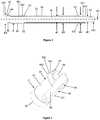
- FIG. 1there is shown an assembly of two bracelet links M1, M2 through the assembly device 3, being assembled, according to a first embodiment of the invention.
- the link M1is composed of two outer meshes M1a, M1b secured to one another, in known manner, in particular by a central stitch M1c.
- messagesmeans here designating a unit, or a single element, of a link.
- the link M1could be monoblock.
- the two outer meshes M1a, M1b and the central mesh M1cdelimit a central housing 10 for receiving a lateral end portion 20 of the link M2 of which only the central mesh is shown in the figures.
- the assembly device 3comprises a screw 4 and a pivoting guide axis 5, which we can sometimes call more simply "axis 5" thereafter.
- the screw 4comprises a head portion 40, cylindrical in shape and of diameter D1, an intermediate portion (or body portion) 41, cylindrical in shape and of diameter d1, and a threaded end portion 42.
- the diameter D1is greater than the diameter d1.
- the head portion 40incorporates a screw head 400.
- the head 40 and intermediate (or body) parts 41are separated by an annular bearing surface 44. They are integral with one another and form here a monoblock component.
- the end portion 42comprises a threaded section 420, at one of its ends, and an annular junction section 421, at its other end, connected to each other.
- the annular junction section 421is in the form of a ring which is distinct from the screw 4, of external and internal diameters respectively equal to or substantially equal to the diameters D1 and d1 of the screw 4. It is for example secured to the end portion 42 of the screw 4 by driving or welding.
- One end of the ring 421forms a bearing surface 423 receiving the support of a second end 53 of the pivoting guide axis 5.
- the threaded section 420has an outer diameter here equal to or substantially equal to the diameter d1.
- the pivoting guide axis 5has a tubular cylindrical shape with axis AX, corresponding to the axis of the screw 4, and has a first open end 52 and a second open end 53.
- inner housing 50receiving the screw 4 which is coaxial with the screw 4.
- the inner diameter of the axis 5is equal to, or substantially equal to, the diameter d1 of the screw 4. Its outer diameter is substantially equal to the diameter D1 of the screw 4.
- Its central portionhas a peripheral surface 55 forming a pivot surface of a second link M2 relative to a first link M1.
- this pivot guide axis 5can be made of sintered ceramic, or composite material formed of a mixture of ceramic and a metal, or a polymer (thermoplastic for example). This material reduces frictional wear.
- the teaching of the document EP2057914can for example be applied.
- the guide pin 5can be made of steel.
- the screw 4 and / or the annular junction section 421, as well as the links M1, M2,may advantageously be made of steel or a precious metal, such as gold or platinum.
- the assembly device 3finally comprises an elastic ring 6, of which a first end 62 comprises an annular shape of outside diameter substantially equal to D1, which rests on the bearing surface 44 defined by the head 40 of the screw 4. It comprises a second end 63 which abuts with the end 52 of the pivoting guide axis 5.
- the elastic ring 6is more particularly represented on the figure 4 . It therefore comprises a first end forming an annular base 62 of diameter substantially equal to D1, surrounding the screw 4, from which extend two elastic tabs 65 in a longitudinal direction, that is to say parallel to the 6. As a remark, when the assembly device 3 is mounted, this axis of the elastic ring merges with the axis AX of the axis 5 as well as with the axis of the device. assembly 3.
- the two elastic tabs 65 of the ring 6are in the form of portions of cylinders, truncated by two longitudinal notches 66. Each elastic tab 65 comprises a first portion 67 in the form of a portion of a cylinder, with a diameter slightly smaller than the diameter of the annular base 62.
- Each elastic tab 65comprises a head 68, arranged to the second end 63 of the elastic ring 6.
- These heads 68have at their respective ends of cylinder portions of diameter substantially equal to the diameter of the annular base 62 which is here substantially equal to the diameter D1 of the screw 4.
- These heads 68further comprise an annular portion 680 of diameter D2, delimited by two inclined flanks 681, 682 to facilitate respectively the insertion and removal of the assembly device 3, as will be detailed later.
- the diameter D2is greater than the diameter D1.
- the annular portion 680 of larger diameterthus forms a protruding peripheral zone, or bulge, of the elastic ring 6, as well as of the assembly device 3 after its assembly, which fulfills the function of axially locking the assembly device, by cooperation with an obstacle of a link.
- This annular portion 680is indeed intended to be inserted in a particular zone of complementary shape (the zone 120) arranged in a link to be assembled, as will be detailed later.
- the elastic ring 6is intended for mounting to the head 40 of the screw 4.
- the latterhas a reduced diameter section d2 vis-à-vis the elastic tabs 65, to release a space 401 between the outer peripheral surface of the screw 4 and the elastic tabs 65, thus allowing their deformation in the direction of the screw 4.
- the central mesh of the second link M2is traversed by a cylindrical bore 21 through which the assembly device 3 passes, with a diameter substantially equal to or slightly greater than that of D1, in its lateral end portion 20.
- the mesh M1a of the first link M1comprises a hole 11 for receiving the threaded end 420 of the assembly device 3, provided with a tapping 110.
- the hole 11is here a blind hole. Alternatively, it could cross the mesh M1a.
- the hole 11is slightly wider, near its mouth on the housing 10, so as to form a bearing 111 acting as positioning stop of the screw 4 at the end of screwing, receiving more particularly the support of the end 422 end of the annular section junction 421.
- the mesh M1b of the first link M1is traversed by a piercing or an opening 12 through which the assembly device 3 passes, shaped to house the elastic ring 6.
- the bore 12comprises a zone 120 of smaller diameter, surrounded by two inclined sides 121, 122. The diameter of this zone 120 remains greater than or equal to the diameter of the pivoting guide axis 5 to allow its insertion without resistance. through the opening 12.
- the axis 5is interposed between two abutment surfaces, formed on the one hand by the bearing surface 44, by means of the interposed elastic ring 6, and on the other hand by the end 423 of the annular junction section 421 of the free end of the end portion 42.
- a clearancecan be provided at these abutment surfaces.
- the axis 5can thus remain mobile in rotation around the screw 4, but blocked axially by the screw head 40 and the ring-shaped annular section 421 in the form of a ring.
- the axis 5may be secured to the screw, for example by driving or welding on the body of the screw 4, in which case its rotation relative to the screw 4 will be prevented.
- this rotationcan be prevented by means of a non-circular profile of a surface corresponding to the screw 4 and / or of the axis 5. This solution can in particular be retained if the axis is in a material difficult to hunt or solder, like ceramic.
- the links M1 and M2are placed in the assembly position.
- the lateral end portion 20 of the central mesh of the second link M2is introduced into the housing 10 formed between the two meshes M1a and M1b of the first link M1.
- the openings 11, 21 and 12are aligned to form a receiving passage of the assembly device 3.
- the assembly device 3is introduced through this passage formed by the openings 11, 21 and 12, until the portion 680 of larger diameter of the elastic ring 6 comes to cooperate with a first inclined flank 121 of a zone 120 of reduced diameter of the opening 12 of the mesh M1b.
- the figure 7represents the intermediate situation in which the portion 680 of larger diameter of the elastic tabs 65 comes into contact with the inclined first sidewall 121.
- the threaded section 420 of the screw 4cooperates with the corresponding threading 110 of the opening 11 of the other lateral mesh M1a of the first link M1.
- the screwing of the screw 4makes it possible to continue its insertion within the openings 11, 21, and 12.
- the screw 4is turned, for example by an operator, by driving in rotation of the screw head 400.
- the tightening torque exerted to rotate the screw 4must be greater than the resisting torque exerted by the contact of the elastic ring 6 against the sidewall 121 inside the opening 12. In other words, the operator must overcome the frictional torque exerted by this contact.
- the screw 4moves in a helical movement having an axial component directed in the screwing direction: this screwing begins as soon as the threaded end 420 of the screw 4 engages in the tapping 110 of the mesh M1a.
- the screw 4is driven in axial translation, which causes the axial translation of the axis 5 and the assembly assembly assembly, which thus enters the passage formed by the openings 11, 21 and 12 crossing the links M1 and M2.
- the elastic tabs 65 of the elastic ring 6are folded towards the surface of the screw 4 within the space 401, which allows the portion 680 of larger diameter of the elastic ring 6 of retracting to exceed the zone 120 of reduced diameter of the opening 12.
- the first inclined flank 681 of the end of the elastic ring 6slides against an inclined flank 121 of similar slope of the zone 120 of reduced diameter of the opening 12.
- the figure 8represents the final position of the elastic ring 6, when the assembly device 3 has reached its final position, in which the head 40 of the screw 4 is entirely housed within the opening 12.
- This final positionis advantageously defined by a stop formed by a mesh against which the assembly device 3 comes to bear.
- this stopis arranged by a bearing surface 111 at the opening 11 of the mesh M1a.
- the end 422 of the assembly section 421 of the assembly device 3is in abutment against this bearing surface 111 of the opening 11.
- the longitudinal positioning of the assembly device 3 with respect to the links M1 and M2could be achieved by an alternative or additional stop against which the screw 4 would abut.
- the elastic ring 6In the final position of the assembly device 3, the elastic ring 6 has exceeded the zone 120 of the opening 12 to reach a zone of larger diameter, of diameter greater than the diameter D1, in which the elastic tabs 65 of the ring elastic 6 were able to return to their initial configuration, by elastic return. In the final position, the elastic ring is therefore at rest, and its elastic legs do not undergo any stress. Their compression is thus performed for a short time, at the time of insertion of the assembly device, and the elastic ring thus undergoes minimal wear. In the final position, the assembly device thus undergoes no radial stress, no clamping on its outer surface. Alternatively, the ring could remain compressed and constrained in its final position, to provide additional frictional resistance to axial locking.
- the figures 10 and 11represent a second embodiment of the assembly device 3 of the invention. For the sake of clarity, only the elements that differ from the first described embodiment will now be described.
- the annular joint section 421 provided in the first embodimentis omitted, and the pivoting guide axis 5 'extends to the end portion of the screw 4, abutting direct against the scope 111 of the opening 11 of the mesh M1a.
- the elastic ring 6 'comprises an annular base 62' disposed in the extension of the first end 52 'of the axis 5' pivotally guide.
- the end 68 'of these elastic tabs 65'can bear on the bearing surface 44 of the head 40 of the screw 4.
- the inner surface of the opening 12 of the mesh M1balso forms a single flank 122 allowing the removal of the assembly device 3, but preventing unintended unscrewing, according to a mechanism similar to that of the first embodiment.
- the retraction of the elastic ring 6 'in a space 401 formed by a groove of the screw 4is formed by the mouth of the opening 12, which receives the head 40 of the screw 4 in the final position.
- the figure 12represents a third embodiment, similar to the previous embodiment, in which the pivoting axis 5 "also integrates the elastic ring 6".
- the axis 5 "of pivoting guidecomprises in one piece the axis 5, the annular junction section 421 and the elastic ring 6 of the first embodiment, in one piece .
- a portion of the body of the screwcould directly represent the pivoting guide axis.
- the pivoting guide axis 5 and the screw 4 of the previous embodimentswould no longer form two separate parts but one piece.
- the body of the screwcould include a groove towards the head of the screw, within which would be fixed an elastic ring.
- This elastic ringcould be in the form of a split ring, to form elastic tabs. This embodiment would have the advantage of minimizing the number of parts used.
- the assembly devicefinally comprises a first element filling the screwing function, in the form of a threaded part, for a suitable and removable attachment of the assembly device, and a second element axial locking device, in the form of an elastic ring, fulfilling the function of axial locking of the assembly device during the low stress induced especially during the wearing of the bracelet, in order to ultimately prevent inadvertent unscrewing of the first element.
- the second locking elementis here in the form of an elastic ring, having two elastic tabs, extending in a longitudinal direction, parallel to the axis of the assembly device.
- the elastic ringcould alternatively comprise three or more elastic tabs, or even a single elastic tab.
- the elastic ringcould be in the form of a split ring implemented for example by a wire spring. Alternatively, several elastic rings could be used.
- the elastic ringis rotatably mounted around the body of the screw.
- itcould be mounted around the pivoting guide axis.
- itmay either be formed by a separate element, or be integral with the pivoting guide shaft, or even the screw.
- the elastic ringcan be fixed on the body of the screw.
- This elastic ringcould be in any other geometric form, comprising one or more parts co-operating by obstacle with a particular geometry part of a link, forming a narrowing, to represent an obstacle to the axial displacement of the elastic ring, sufficient to block its displacement and that of the entire assembly device, when wearing a simple bracelet, but allowing the release of the elastic ring during a screwing effort or manual unscrewing of the assembly device.
- the ringmay comprise one or two inclined sides to promote its elastic deformation during removal or insertion.
- the geometry and the material of the elastic ringare defined so that its compression generates a minimal resistive torque during screwing or unscrewing of the screw, while axially locking the assembly device during the stresses exerted by a simple wear.
- the elastic ringis made of spring steel, for example Phynox, or Phytime, or Nivaflex.
Landscapes
- Engineering & Computer Science (AREA)
- General Engineering & Computer Science (AREA)
- Mechanical Engineering (AREA)
- Bolts, Nuts, And Washers (AREA)
- Adornments (AREA)
- Hooks, Suction Cups, And Attachment By Adhesive Means (AREA)
- Pivots And Pivotal Connections (AREA)
- Snaps, Bayonet Connections, Set Pins, And Snap Rings (AREA)
- Clamps And Clips (AREA)
Description
Translated fromFrenchL'invention concerne un dispositif d'assemblage, ou d'attache, à pivotement d'au moins deux pièces, notamment deux maillons d'un bracelet, par exemple d'un bracelet de montre.The invention relates to an assembly device, or attachment, pivoting at least two parts, including two links of a bracelet, for example a watch band.
Un tel dispositif d'assemblage permet d'assembler des maillons, généralement par le biais d'un axe de guidage en pivotement et d'une vis, les maillons assemblés pouvant se déplacer en rotation les uns par rapport aux autres.Such an assembly device makes it possible to assemble links, generally via a pivoting guide pin and a screw, the assembled links being able to move in rotation relative to one another.
Un assemblage de ce type est exposé à un risque de dévissage intempestif. Ce problème, bien connu des horlogers, est causé par les mouvements répétés des maillons les uns par rapport aux autres lors du porter du bracelet ou par des chocs.An assembly of this type is exposed to a risk of inadvertent unscrewing. This problem, well known to watchmakers, is caused by the repeated movements of the links relative to each other when wearing the bracelet or by shocks.
Pour résoudre ce problème, on connaît par le document
La présente invention vient améliorer la situation.The present invention improves the situation.
A cet effet, l'invention concerne un dispositif d'assemblage pour attacher à pivotement au moins deux pièces, tel que défini par la revendication 1. L'invention concerne aussi un ensemble comportant au moins deux pièces attachées à l'aide du dispositif d'assemblage tel que précédemment défini.To this end, the invention relates to an assembly device for pivotably attaching at least two parts, as defined by claim 1. The invention also relates to an assembly comprising at least two parts attached using the device of the invention. assembly as previously defined.
L'invention concerne également un bracelet comportant au moins deux maillons attachés à l'aide du dispositif d'assemblage tel que précédemment défini.The invention also relates to a bracelet comprising at least two links attached using the assembly device as previously defined.
L'invention concerne enfin un procédé d'assemblage à pivotement d'au moins deux pièces à l'aide du dispositif d'assemblage tel que précédemment défini, caractérisé en ce qu'il comprend, après introduction du dispositif d'assemblage dans une ouverture traversant une deuxième pièce, une étape de vissage lors de laquelle la vis est vissée dans une première pièce, entraînant en translation axiale l'axe de guidage en pivotement du dispositif d'assemblage et la déformation élastique de la bague élastique du dispositif d'assemblage.The invention finally relates to a method of pivotally assembling at least two parts using the assembly device as previously defined, characterized in that it comprises, after introduction of the assembly device into an opening passing through a second part, a screwing step in which the screw is screwed into a first part, driving in axial translation the pivoting guide axis of the assembly device and the elastic deformation of the elastic ring of the assembly device .
L'invention est plus précisément définie par les revendications.The invention is more precisely defined by the claims.
Ces objets, caractéristiques et avantages de la présente invention seront exposés en détail dans la description suivante de modes de réalisation particuliers faits à titre non-limitatif en relation avec les figures jointes parmi lesquelles :
- La
figure 1 représente un assemblage de deux maillons d'un bracelet comportant un dispositif d'assemblage selon une première forme de réalisation de l'invention, en cours de montage. - La
figure 2 représente le dispositif d'assemblage selon la première forme de réalisation. - La
figure 3 représente une vue en coupe axiale du dispositif d'assemblage selon la première forme de réalisation. - La
figure 4 représente une bague élastique du dispositif d'assemblage selon la première forme de réalisation. - La
figure 5 représente l'assemblage de lafigure 1 , après montage, en vue de coupe axiale selon A-A. - La
figure 6 représente l'assemblage de lafigure 1 en vue de coupe axiale selon B-B. - La
figure 7 représente l'assemblage de lafigure 1 au niveau de la bague élastique dans une phase intermédiaire de son montage, en vue de coupe axiale selon A-A. - La
figure 8 représente l'assemblage de lafigure 1 dans sa position finale d'assemblage au niveau de la bague élastique, en vue de coupe axiale selon A-A. - La
figure 9 représente l'assemblage de lafigure 1 dans sa position finale au niveau de la partie terminale de la vis du dispositif d'assemblage, en vue de coupe axiale selon A-A. - La
figure 10 représente une vue en coupe axiale du dispositif d'assemblage selon une deuxième forme de réalisation. - La
figure 11 représente une vue en coupe axiale du dispositif d'assemblage au niveau de la bague élastique selon la deuxième forme de réalisation. - La
figure 12 représente une vue en coupe axiale du dispositif d'assemblage selon une troisième forme de réalisation.
- The
figure 1 represents an assembly of two links of a bracelet comprising an assembly device according to a first embodiment of the invention, being assembled. - The
figure 2 represents the assembly device according to the first embodiment. - The
figure 3 is an axial sectional view of the assembly device according to the first embodiment. - The
figure 4 represents an elastic ring of the assembly device according to the first embodiment. - The
figure 5 represents the assembly of thefigure 1 , after assembly, for axial section along AA. - The
figure 6 represents the assembly of thefigure 1 in view of axial section along BB. - The
figure 7 represents the assembly of thefigure 1 at the level of the elastic ring in an intermediate phase of its assembly, for axial section along AA. - The
figure 8 represents the assembly of thefigure 1 in its final assembly position at the level of the elastic ring, for axial section along AA. - The
figure 9 represents the assembly of thefigure 1 in its final position at the end portion of the screw of the assembly device, for axial section along AA. - The
figure 10 represents an axial sectional view of the assembly device according to a second embodiment. - The
figure 11 represents an axial sectional view of the assembly device at the level of the elastic ring according to the second embodiment. - The
figure 12 is an axial sectional view of the assembly device according to a third embodiment.
L'invention concerne un dispositif d'assemblage, ou d'articulation, à pivotement destiné à assembler aux moins deux pièces pouvant pivoter l'une par rapport à l'autre. Il peut être utilisé pour assembler des maillons, par exemple des maillons d'un bracelet tel qu'un bracelet de montre.The invention relates to an assembly device, or hinge, pivoting for assembling at least two parts that can pivot relative to each other. It can be used to assemble links, for example links of a bracelet such as a watch strap.
Les éléments identiques ou correspondants, qui sont représentés sur les différentes figures, portent les mêmes références, sauf indication contraire. Par convention, nous appellerons direction longitudinale la direction parallèle à l'axe du dispositif d'assemblage et direction transversale la direction perpendiculaire.The identical or corresponding elements, which are represented in the various figures, bear the same references, unless otherwise indicated. By convention, we will call longitudinal direction the direction parallel to the axis of the assembly device and transverse direction the perpendicular direction.
Les
Sur la
Le maillon M1 est composé de deux mailles extérieures M1a, M1b solidarisées l'une à l'autre, de façon connue, notamment par une maille centrale M1c. Par le terme « maille », on entend ici désigner une unité, ou un élément simple, d'un maillon. En variante, le maillon M1 pourrait être monobloc. Les deux mailles extérieures M1a, M1b et la maille centrale M1c délimitent un logement central 10 de réception d'une portion d'extrémité latérale 20 du maillon M2 dont seule la maille centrale est représentée sur les figures.The link M1 is composed of two outer meshes M1a, M1b secured to one another, in known manner, in particular by a central stitch M1c. By the term "mesh" means here designating a unit, or a single element, of a link. Alternatively, the link M1 could be monoblock. The two outer meshes M1a, M1b and the central mesh M1c delimit a
En référence à la
En référence à la
La partie tête 40 intègre une tête de vis 400. Les parties tête 40 et intermédiaire (ou corps) 41 sont séparées par une portée annulaire 44. Elles sont solidaires l'une de l'autre et forment ici un composant monobloc.The
La partie terminale 42 comprend une section filetée 420, à l'une de ses extrémités, et une section annulaire de jonction 421, à son autre extrémité, reliées l'une à l'autre. La section annulaire de jonction 421 se présente comme un anneau distinct de la vis 4, de diamètres extérieur et intérieur respectivement égaux, ou sensiblement égaux, aux diamètres D1 et d1 de la vis 4. Elle est par exemple solidarisée à la partie terminale 42 de la vis 4 par chassage ou soudage. Une extrémité de l'anneau 421 forme une portée 423 recevant l'appui d'une seconde extrémité 53 de l'axe 5 de guidage en pivotement. La section filetée 420 a un diamètre extérieur ici égal ou sensiblement égal au diamètre d1.The
L'axe 5 de guidage en pivotement présente une forme cylindrique tubulaire d'axe AX, correspondant à l'axe de la vis 4, et comporte une première extrémité ouverte 52 et une deuxième extrémité ouverte 53. Il ménage un logement interne 50, de réception de la vis 4 qui est coaxial à la vis 4. Le diamètre interne de l'axe 5 est égal, ou sensiblement égal, au diamètre d1 de la vis 4. Son diamètre externe est sensiblement égal au diamètre D1 de la vis 4. Sa partie centrale présente une surface périphérique 55 formant une surface de pivotement d'un second maillon M2 relativement à un premier maillon M1.The pivoting
Avantageusement, cet axe 5 de guidage en pivotement peut être réalisé en céramique frittée, ou en matériau composite formé d'un mélange de céramique et d'un métal, ou d'un polymère (thermoplastique par exemple). Ce matériau permet de réduire l'usure par frottement. L'enseignement du document
Le dispositif d'assemblage 3 comprend enfin une bague élastique 6, dont une première extrémité 62 comprend une forme annulaire de diamètre extérieur sensiblement égal à D1, qui se trouve en appui sur la portée 44 définie par la tête 40 de la vis 4. Elle comprend une seconde extrémité 63 qui vient en butée avec l'extrémité 52 de l'axe 5 de guidage en pivotement.The
La bague élastique 6 est plus particulièrement représentée sur la
La maille centrale du second maillon M2 est traversée par un perçage 21 cylindrique de passage du dispositif d'assemblage 3, de diamètre sensiblement égal ou légèrement supérieur à D1, dans sa portion d'extrémité latérale 20.The central mesh of the second link M2 is traversed by a
La maille M1a du premier maillon M1 comporte un trou 11 de réception de l'extrémité filetée 420 du dispositif d'assemblage 3, muni d'un taraudage 110. Le trou 11 est ici un trou borgne. En variante, il pourrait traverser la maille M1a. Le trou 11 est légèrement plus large, à proximité de son embouchure sur le logement 10, de manière à former une portée 111 jouant le rôle de butée de positionnement de la vis 4 en fin de vissage, recevant plus particulièrement l'appui de l'extrémité 422 terminale de la section annulaire de jonction 421.The mesh M1a of the first link M1 comprises a
La maille M1b du premier maillon M1 est traversée par un perçage ou une ouverture 12 de passage du dispositif d'assemblage 3, conformé pour loger la bague élastique 6. Comme cela apparaît plus particulièrement sur les
Le dispositif d'assemblage 3 est préassemblé par la mise en oeuvre des étapes décrites ci-après :
- Lors d'une première étape, la bague élastique 6
et l'axe 5 sont disposés autour du corps de la vis 4. Pour cela, la bague élastique 6 est d'abord insérée par l'extrémité terminale 42 de la vis, jusqu'à ce que sa base annulaire 62 vienne en appui contre la portée 44 au niveau de la tête 40 de la vis. Ensuite,l'axe 5 est de même inséré par l'extrémité terminale de la vis, jusqu'à ce que sa première extrémité 52 vienne en appui contre la seconde extrémité 63 de la bague élastique 6. En remarque, la bague élastique 6,l'axe 5 et la vis 4 sont ainsi assemblés de manière coaxiale, et l'axe du dispositif d'assemblage 3 assemblé se confond donc avec l'axe AX de la vis 4 et de l'axe 5 et avec l'axe central de la bague élastique 6. - Lors d'une seconde étape, la section annulaire de jonction 421 de la partie terminale 42 est introduite par l'extrémité terminale de la vis, jusqu'à ce que sa première extrémité 423 vienne en appui contre la seconde extrémité 53 de l'axe 5. Ensuite, cette section annulaire de jonction 421 est solidarisée à la vis.
- In a first step, the
elastic ring 6 and theaxis 5 are arranged around the body of thescrew 4. For this, theelastic ring 6 is first inserted by theend end 42 of the screw, until itsannular base 62 bears against the bearingsurface 44 at the level of thehead 40 of the screw. Then, theaxis 5 is likewise inserted by the end end of the screw, until itsfirst end 52 bears against thesecond end 63 of theelastic ring 6. As a remark, theelastic ring 6, theaxis 5 and thescrew 4 are thus assembled coaxially, and the axis of the assembledassembly device 3 thus merges with the axis AX of thescrew 4 and theaxis 5 and with the central axis of theelastic ring 6. - In a second step, the
annular junction section 421 of theend portion 42 is introduced through the end end of the screw, until itsfirst end 423 bears against thesecond end 53 of the axis. 5. Then, thisannular junction section 421 is secured to the screw.
A l'issue de ces étapes de montage du dispositif d'assemblage 3, l'axe 5 se trouve interposé entre deux surfaces de butée, constituées d'une part par la portée 44, par l'intermédiaire de la bague élastique 6 interposée, et d'autre part par l'extrémité 423 de la section annulaire de jonction 421 de l'extrémité libre de la partie terminale 42. Un jeu peut toutefois être ménagé au niveau de ces surfaces de butée. L'axe 5 peut ainsi rester mobile en rotation autour de la vis 4, mais bloqué axialement par la tête de vis 40 et par la section annulaire de jonction 421 en forme d'anneau.At the end of these assembly steps of the
En variante, l'axe 5 peut être solidarisé à la vis, par exemple par chassage ou soudage sur le corps de la vis 4, auquel cas sa rotation relativement à la vis 4 sera empêchée. En variante, cette rotation peut être empêchée par le biais d'un profil non circulaire d'une surface en correspondance de la vis 4 et/ou de l'axe 5. Cette solution peut notamment être retenue si l'axe est dans un matériau difficile à chasser ou souder, comme en céramique.Alternatively, the
On va maintenant décrire, en référence avec les
Lors d'une première étape, les maillons M1 et M2 sont placés en position d'assemblage. A cet effet, la portion d'extrémité latérale 20 de la maille centrale du second maillon M2 est introduite dans le logement 10 formé entre les deux mailles M1a et M1b du premier maillon M1. Les ouvertures 11, 21 et 12 sont alignées de manière à former un passage de réception du dispositif d'assemblage 3.In a first step, the links M1 and M2 are placed in the assembly position. For this purpose, the
Lors d'une deuxième étape, le dispositif d'assemblage 3 est introduit à travers ce passage formé par les ouvertures 11, 21 et 12, jusqu'à ce que la portion 680 de plus grand diamètre de la bague élastique 6 vienne coopérer avec un premier flanc incliné 121 d'une zone 120 de diamètre réduit de l'ouverture 12 de la maille M1b. La
Lors d'une troisième étape, le vissage de la vis 4 permet de poursuivre son insertion au sein des ouvertures 11, 21, et 12. Pour cela, la vis 4 est tournée, par exemple par un opérateur, par entraînement en rotation de la tête de vis 400. Le couple de vissage exercé pour faire tourner la vis 4 doit être supérieur au couple résistant exercé par le contact de la bague élastique 6 contre le flanc 121 à l'intérieur de l'ouverture 12. Autrement dit, l'opérateur doit vaincre le couple de friction exercé par ce contact.In a third step, the screwing of the
Sous l'action d'être tournée, la vis 4 se déplace selon un mouvement hélicoïdal comportant une composante axiale dirigée dans le sens de vissage : ce vissage commence dès que l'extrémité filetée 420 de la vis 4 s'engage dans le taraudage 110 de la maille M1a. Lors de son déplacement hélicoïdal, la vis 4 est entraînée en translation axiale, ce qui provoque la translation axiale de l'axe 5 et de l'ensemble du dispositif d'assemblage, qui pénètre ainsi dans le passage formé par les ouvertures 11, 21 et 12 traversant les maillons M1 et M2.Under the action of being turned, the
Dans ce mouvement d'insertion, les pattes élastiques 65 de la bague élastique 6 sont rabattues vers la surface de la vis 4 au sein de l'espace 401, ce qui permet à la portion 680 de plus grand diamètre de la bague élastique 6 de s'escamoter pour dépasser la zone 120 de diamètre réduit de l'ouverture 12. Dans ce mouvement de la bague élastique, le premier flanc incliné 681 de l'extrémité de la bague élastique 6 glisse contre un flanc incliné 121 de pente semblable de la zone 120 de diamètre réduit de l'ouverture 12. Ces deux flancs inclinés permettent ainsi la déformation élastique adéquate de la bague élastique 6 lors de l'insertion du dispositif d'assemblage 3. En remarque, la zone 120 et la géométrie de la bague élastique 6 sont configurées pour obtenir l'escamotage de la bague lors de son insertion, puis son maintien en position finale, sans gêner l'insertion ni le retrait du reste du dispositif d'assemblage 3.In this insertion movement, the
La
Dans la position finale du dispositif d'assemblage 3, la bague élastique 6 a dépassé la zone 120 de l'ouverture 12 pour atteindre une zone de diamètre plus large, de diamètre supérieur au diamètre D1, dans laquelle les pattes élastiques 65 de la bague élastique 6 ont pu retrouver leur configuration initiale, par retour élastique. Dans la position finale, la bague élastique se trouve donc au repos, et ses pattes élastiques ne subissent aucune contrainte. Leur compression est donc réalisée pendant un instant réduit, au moment de l'insertion du dispositif d'assemblage, et la bague élastique subit ainsi une usure minimale. Dans la position finale, le dispositif d'assemblage ne subit ainsi aucune contrainte radiale, aucun serrage sur sa surface extérieure. En variante, la bague pourrait rester compressée et contrainte dans sa position finale, pour offrir une résistance par frottement complémentaire au blocage axial.In the final position of the
En position finale du dispositif d'assemblage 3, le maintien axial de l'axe 5 de guidage en pivotement vis-à-vis des maillons M1, M2 est principalement opéré par la force exercée par les filets 420 de la vis 4 au sein du trou taraudé 11 du maillon M1. Les maillons M1 et M2 sont ainsi assemblés, le maillon M2 pouvant pivoter par rapport au maillon M1 autour de l'axe 5 de guidage en pivotement.In the final position of the
Lors du porter du bracelet ou de chocs, des contacts répétitifs entre la surface extérieure 55 de l'axe 5 et la paroi interne du trou 21 du maillon central M2 se produisent. Cela induit de légers déplacements angulaires de l'axe 5 par rapport au maillon extérieur M1. Ces déplacements angulaires seraient susceptibles de produire un dévissage inopiné de la vis 4 et un démontage accidentel du dispositif d'assemblage 3. Toutefois, un tel événement ne peut pas se produire avec la solution selon ce mode de réalisation, car un second flanc incliné 122 de la zone 120 de diamètre réduit de l'ouverture 12 forme un obstacle contre lequel l'extrémité 68 des pattes élastiques 65 de la bague élastique 6, en saillie sur le dispositif d'assemblage 3, reste bloquée, empêchant tout mouvement arrière intempestif du dispositif d'assemblage 3. Grâce à cela, la vis 4 n'est pas impactée par les contacts répétés entre le maillon central M2 et l'axe 5. Elle reste dans sa position vissée. Le risque de dévissage intempestif est ainsi éliminé.When wearing the bracelet or shocks, repetitive contacts between the
Pour démonter le dispositif d'assemblage 3, afin de désolidariser les maillons M1 et M2, il suffit à un opérateur de tourner la vis 4 dans le sens de dévissage, par le biais de la tête de vis 400, en exerçant un couple de dévissage supérieur au couple résistant formé par la coopération des pattes élastiques 65 avec l'ouverture 12, explicitée ci-dessus. Sous l'action d'être tournée dans le sens de dévissage, la vis 4 effectue un mouvement hélicoïdal qui permet le démontage du dispositif d'assemblage 3, lors duquel les pattes élastiques 65 sont soumises à une compression temporaire, de manière similaire et réversible à la phase de vissage explicitée précédemment. Dans cette phase, les autres flancs inclinés 682, 122 de respectivement la portion 680 de plus grand diamètre de la bague élastique et de la zone 120 de diamètre réduit de l'ouverture 12 coopèrent pour permettre l'escamotage élastique de la bague élastique.To disassemble the
Les
Dans cette deuxième forme de réalisation, la section annulaire de jonction 421 prévue dans le premier mode de réalisation est supprimée, et l'axe 5' de guidage en pivotement s'étend jusqu'à la partie terminale de la vis 4, venant en butée directe contre la portée 111 de l'ouverture 11 de la maille M1a. D'autre part, la bague élastique 6' comprend une base annulaire 62' disposée dans le prolongement de la première extrémité 52' de l'axe 5' de guidage en pivotement. Les pattes élastiques 65' s'étendent depuis cette base annulaire 62', dans une direction opposée à celle du premier mode de réalisation. L'extrémité 68' de ces pattes élastiques 65' peut venir en appui sur la portée 44 de la tête 40 de la vis 4. La surface intérieure de l'ouverture 12 de la maille M1b forme aussi un seul flanc 122 permettant le retrait du dispositif d'assemblage 3, mais empêchant son dévissage inopiné, selon un mécanisme semblable à celui du premier mode de réalisation. L'escamotage de la bague élastique 6' dans un espace 401 formé par une gorge de la vis 4 est réalisé par l'embouchure de l'ouverture 12, qui reçoit la tête 40 de la vis 4 en position finale.In this second embodiment, the annular
La
Dans un quatrième mode de réalisation non représenté, une partie du corps de la vis pourrait représenter directement l'axe de guidage en pivotement. Dans un tel mode de réalisation, l'axe 5 de guidage en pivotement et la vis 4 des modes de réalisation précédents ne formeraient plus deux pièces distinctes mais une seule pièce. Dans ce mode de réalisation, le corps de la vis pourrait comprendre une gorge vers la tête de la vis, au sein de laquelle serait fixée une bague élastique. Cette bague élastique pourrait se présenter sous la forme d'un anneau fendu, pour former des pattes élastiques. Cette réalisation présenterait l'avantage de minimiser le nombre de pièces utilisées.In a fourth embodiment not shown, a portion of the body of the screw could directly represent the pivoting guide axis. In such an embodiment, the pivoting
Dans tous les modes de réalisation décrits précédemment, le dispositif d'assemblage comprend finalement un premier élément remplissant la fonction de vissage, sous la forme d'une partie filetée, pour une fixation adéquate et amovible du dispositif d'assemblage, et un second élément de blocage axial, sous la forme d'une bague élastique, remplissant la fonction de blocage axial du dispositif d'assemblage lors des faibles sollicitations induites notamment lors du porter du bracelet, afin d'éviter finalement le dévissage intempestif du premier élément.In all the embodiments described above, the assembly device finally comprises a first element filling the screwing function, in the form of a threaded part, for a suitable and removable attachment of the assembly device, and a second element axial locking device, in the form of an elastic ring, fulfilling the function of axial locking of the assembly device during the low stress induced especially during the wearing of the bracelet, in order to ultimately prevent inadvertent unscrewing of the first element.
Ces deux éléments ont été agencés précédemment sur deux extrémités différentes du dispositif d'assemblage, pour agir par coopération au sein de deux mailles de bord distinctes d'un maillon de bracelet. En variante, ils peuvent être disposés à proximité l'un de l'autre, pour coopérer au sein d'une même maille. Par exemple, la section filetée de la vis pourrait jouxter la tête de vis. En variante, la bague élastique pourrait être agencée vers l'extrémité de la vis opposée à la tête.These two elements have been previously arranged on two different ends of the assembly device, to act by cooperation within two distinct edge meshes of a bracelet link. Alternatively, they may be arranged close to each other, to cooperate within the same mesh. For example, the threaded section of the screw could be adjacent to the screw head. Alternatively, the elastic ring could be arranged towards the end of the screw opposite the head.
Le second élément de blocage se présente ici sous la forme d'une bague élastique, présentant deux pattes élastiques, s'étendant dans une direction longitudinale, parallèlement à l'axe du dispositif d'assemblage. Naturellement, la bague élastique pourrait en variante comprendre trois ou plus de trois pattes élastiques, voire une seule patte élastique. En variante, la bague élastique pourrait se présenter sous la forme d'un anneau fendu mis en oeuvre par exemple par un ressort fil. En variante, plusieurs bagues élastiques pourraient être utilisées.The second locking element is here in the form of an elastic ring, having two elastic tabs, extending in a longitudinal direction, parallel to the axis of the assembly device. Naturally, the elastic ring could alternatively comprise three or more elastic tabs, or even a single elastic tab. Alternatively, the elastic ring could be in the form of a split ring implemented for example by a wire spring. Alternatively, several elastic rings could be used.
Préférentiellement, la bague élastique est montée mobile en rotation autour du corps de la vis. En variante, elle pourrait être montée autour de l'axe de guidage en pivotement. De plus, elle peut soit être formée par un élément distinct, soit être solidaire de l'axe de guidage en pivotement, voire de la vis. Ainsi, la bague élastique peut être fixée sur le corps de la vis.Preferably, the elastic ring is rotatably mounted around the body of the screw. Alternatively, it could be mounted around the pivoting guide axis. In addition, it may either be formed by a separate element, or be integral with the pivoting guide shaft, or even the screw. Thus, the elastic ring can be fixed on the body of the screw.
Cette bague élastique pourrait se présenter sous toute autre forme géométrique, comprenant une ou plusieurs parties coopérant par obstacle avec une partie de géométrie particulière d'un maillon, formant un rétrécissement, pour représenter un obstacle au déplacement axial de la bague élastique, suffisant pour bloquer son déplacement et celui de l'ensemble du dispositif d'assemblage, lors du simple porter d'un bracelet, mais permettant la libération de la bague élastique lors d'un effort de vissage ou dévissage manuel du dispositif d'assemblage. Pour cela, la bague peut comprendre un ou deux flancs inclinés pour favoriser sa déformation élastique lors de son retrait ou insertion.This elastic ring could be in any other geometric form, comprising one or more parts co-operating by obstacle with a particular geometry part of a link, forming a narrowing, to represent an obstacle to the axial displacement of the elastic ring, sufficient to block its displacement and that of the entire assembly device, when wearing a simple bracelet, but allowing the release of the elastic ring during a screwing effort or manual unscrewing of the assembly device. For this, the ring may comprise one or two inclined sides to promote its elastic deformation during removal or insertion.
La géométrie et le matériau de la bague élastique sont définis de sorte que sa compression engendre un couple résistif minimal lors du vissage ou du dévissage de la vis, tout en bloquant axialement le dispositif d'assemblage lors des sollicitations exercées par un simple porter. Avantageusement, la bague élastique est réalisée en acier ressort, par exemple en Phynox, ou en Phytime, ou en Nivaflex.The geometry and the material of the elastic ring are defined so that its compression generates a minimal resistive torque during screwing or unscrewing of the screw, while axially locking the assembly device during the stresses exerted by a simple wear. Advantageously, the elastic ring is made of spring steel, for example Phynox, or Phytime, or Nivaflex.
Claims (15)
- An assembly device (3) for pivotally attaching at least two parts (M1, M2), comprising a screw (4) designed to be screwed into a first piece (M1) and carrying a pivoting guide pin (5) for a second part (M2), the assembly device (3) comprising at least one elastic ring (6) able to work in conjunction with a blocking element of one of the two parts (M1, M2), so as to prevent accidental axial movement of the assembly device (3),characterized in that the elastic ring (6) comprises an annular base (62) from where extend at least two elastic clips (65) parallel to the axis of the assembly device (3), these elastic clips (65) comprising a portion (680) able to work in conjunction with a blocking element of one of the two parts (M1, M2) of greater diameter than the diameter of the pivoting guide pin (5), surrounded by at least one beveled edge (681, 682) to promote the insertion and/or removal of the assembly device (3) into/from the two parts (M1, M2).
- The assembly device as claimed in the previous claim,characterized in that the elastic ring (6) comprises at least one elastic clip (65) arranged on the periphery of the screw (4) and/or of the pivoting guide pin (5).
- The assembly device as claimed in either of claims 1 or 2,characterized in that the elastic ring (6) is arranged around the screw (4), andcharacterized in that there is a space (401) between the elastic clips (65) of the elastic ring (6) and the screw (4) to allow the elastic return of these elastic clips (65) toward the screw (4) during insertion and removal of the assembly device (3) into and from the two parts (M1, M2).
- The assembly device as claimed in one of the previous claimscharacterized in that the screw (4) comprises a part (40) having a first diameter D1 defining a bearing surface (44), a central part (41) of smaller diameter d1 around which is arranged the pivoting guide pin (5) of diameter substantially equal to the first diameter D1, and such that the elastic ring (6) abuts between the bearing surface (44) and the pivoting guide pin (5) and has an elastic part with a portion (680) of greater diameter D2, which is notably greater than the first diameter D1.
- The assembly device as claimed in one of claims 1 to 3,characterized in that the screw (4) comprises a central section around which is arranged the pivoting guide pin (5) andcharacterized in that the elastic ring (6) is integral with the pivoting guide pin (5), arranged at one of its ends, or is even directly formed in the pivoting guide pin (5) with which it forms a single piece.
- The assembly device as claimed in one of the previous claims,characterized in that the screw (4) comprises a head (40), a central part (41) and an end part (42) which comprises a threaded section (420) of smaller diameter than the diameter of the central part (41).
- The assembly device as claimed in one of the previous claims,characterized in that the pivoting guide pin (5) is separate from the screw (4) and rotatably mobile around the screw (4) or fixed relative to the screw (4), orcharacterized in that the pivoting guide pin (5) and the screw (4) form the same part.
- The assembly device as claimed in one of the previous claims,characterized in that the pivoting guide pin (5) is made of sintered ceramic or composite material, notably formed from a mixture of ceramic and metal or a polymer, and/orcharacterized in that the elastic ring (6) is made of spring steel.
- An assembly comprising at least two parts (M1, M2) attached by means of the assembly device (3) as claimed in one of claims 1 to 8.
- The assembly as claimed in the previous claim,characterized in that an opening (12) of a part (M1) comprises a zone (120) of smaller diameter forming an obstacle to the elastic ring (6) preventing the untimely axial removal of the assembly device (3).
- The assembly as claimed in claim 9 or 10,characterized in that the zone (120) of smaller diameter allows the retraction of the elastic ring (6) and the passage of the rest of the assembly device (3) for its insertion into and/or removal from the openings (11, 12, 21) of the parts (M1, M2) to be attached.
- The assembly as claimed in one of claims 9 to 11,characterized in that the elastic ring (6) of the assembly device (3) occupies a non-stressed final position when the two parts (M1, M2) are attached by means of the assembly device (3).
- The assembly as claimed in one of claims 9 to 11,characterized in that the elastic ring (6) and the zone (120) of smaller diameter of the opening (12) of a part (M1) each comprise one or two beveled edges (681, 682, 121, 122) respectively, of similar inclination, to promote the insertion and/or the removal when screwing and/or unscrewing of the assembly device (3) for its insertion and/or removal.
- A bracelet comprising at least one assembly as claimed in one of claims 9 to 13 or at least two links (M1, M2) attached by means of the assembly device (3) as claimed in one of claims 1 to 8.
- A pivoting assembly method for at least two parts (M1, M2) by means of an assembly device (3) as claimed in one of claims 1 to 8,characterized in that it comprises, after introduction of the assembly device (3) into an opening (21) passing through a second part (M2), a screwing step during which the screw (4) is screwed into a first part (M1), driving in axial translation the pivoting guide pin (5) of the assembly device (3) and the elastic deformation of the elastic ring (6) of the assembly device (3).
Priority Applications (4)
| Application Number | Priority Date | Filing Date | Title |
|---|---|---|---|
| EP14166781.6AEP2939560B1 (en) | 2014-05-01 | 2014-05-01 | Device and method for pivotably connecting at least two parts, corresponding set of two assembled parts |
| US14/698,022US9462857B2 (en) | 2014-05-01 | 2015-04-28 | Device and method for pivotal assembly of at least two parts, corresponding assembly of the two assembled parts |
| CN201510319201.2ACN105134752B (en) | 2014-05-01 | 2015-04-30 | Assembly device and method for pivotally attaching at least two parts |
| JP2015092490AJP6667209B2 (en) | 2014-05-01 | 2015-04-30 | Device and method for pivotally assembling at least two parts, and an assembly comprising two parts |
Applications Claiming Priority (1)
| Application Number | Priority Date | Filing Date | Title |
|---|---|---|---|
| EP14166781.6AEP2939560B1 (en) | 2014-05-01 | 2014-05-01 | Device and method for pivotably connecting at least two parts, corresponding set of two assembled parts |
Publications (2)
| Publication Number | Publication Date |
|---|---|
| EP2939560A1 EP2939560A1 (en) | 2015-11-04 |
| EP2939560B1true EP2939560B1 (en) | 2018-07-11 |
Family
ID=50639307
Family Applications (1)
| Application Number | Title | Priority Date | Filing Date |
|---|---|---|---|
| EP14166781.6AActiveEP2939560B1 (en) | 2014-05-01 | 2014-05-01 | Device and method for pivotably connecting at least two parts, corresponding set of two assembled parts |
Country Status (4)
| Country | Link |
|---|---|
| US (1) | US9462857B2 (en) |
| EP (1) | EP2939560B1 (en) |
| JP (1) | JP6667209B2 (en) |
| CN (1) | CN105134752B (en) |
Families Citing this family (1)
| Publication number | Priority date | Publication date | Assignee | Title |
|---|---|---|---|---|
| CA2939560C (en)* | 2014-02-11 | 2019-11-12 | Classic Connectors | Electrical transmission line repair apparatus |
Family Cites Families (18)
| Publication number | Priority date | Publication date | Assignee | Title |
|---|---|---|---|---|
| US2412120A (en)* | 1945-06-28 | 1946-12-03 | Bausch & Lomb | Spectacle temple connection |
| US2939168A (en)* | 1957-12-11 | 1960-06-07 | American Optical Corp | Ophthalmic mountings |
| US3363745A (en)* | 1966-09-20 | 1968-01-16 | Rex Chainbelt Inc | Pivotal connection for links of flat top conveyor |
| JPS5330352B2 (en)* | 1971-12-14 | 1978-08-26 | ||
| FR2408062A1 (en)* | 1977-11-04 | 1979-06-01 | Pflieger Roger | Play-free pivotal joint - has spring washer compressed by pivot screw extending through insert sleeve with projection received in bore of second member |
| FR2492993A1 (en)* | 1980-10-28 | 1982-04-30 | Chevassus Veuve Henri | IMPROVEMENT TO GLASS HINGES |
| CH689439A5 (en)* | 1994-03-22 | 1999-04-30 | Maurice Petignat | Clasp, esp. for watch strap |
| JP2965472B2 (en)* | 1994-10-28 | 1999-10-18 | 日東精工株式会社 | Hinge for glasses |
| CH699811B1 (en)* | 2000-08-11 | 2010-05-14 | Rado Montres Sa | Bracelet with articulated links and a method of assembling such a bracelet |
| US6913411B2 (en)* | 2001-03-12 | 2005-07-05 | Citizen Watch Co., Ltd. | Band coupling structure and method of manufacturing piece member therefor |
| JP2002372023A (en)* | 2001-06-15 | 2002-12-26 | Nitto Seiko Co Ltd | Loosening screw |
| US6418706B1 (en)* | 2001-11-27 | 2002-07-16 | Fossil, Inc. | Watchband link assembly |
| CH695389A5 (en) | 2002-05-29 | 2006-04-28 | Hgt Petitjean S A | External and central links assembling device for watch strap, has screw including proximal and distal sections of different diameters between its threaded part and head, where sections have annular groove to receive shrinkage of hour wheel |
| EP1428451B1 (en)* | 2002-12-11 | 2008-02-13 | Rolex Sa | Bracelet with articulated links |
| JP4366459B2 (en)* | 2003-10-23 | 2009-11-18 | シチズンホールディングス株式会社 | Linkage structure for jewelry band |
| EP2057914B1 (en) | 2007-11-06 | 2016-07-06 | Rolex Sa | Bracelet with articulated links |
| EP2260740A1 (en)* | 2009-06-08 | 2010-12-15 | Rolex Sa | Bracelet made up of articulated links |
| EP2380455B1 (en)* | 2010-04-23 | 2013-03-20 | Montres Rado S.A. | Bracelet with articulated links |
- 2014
- 2014-05-01EPEP14166781.6Apatent/EP2939560B1/enactiveActive
- 2015
- 2015-04-28USUS14/698,022patent/US9462857B2/ennot_activeExpired - Fee Related
- 2015-04-30JPJP2015092490Apatent/JP6667209B2/enactiveActive
- 2015-04-30CNCN201510319201.2Apatent/CN105134752B/ennot_activeExpired - Fee Related
Non-Patent Citations (1)
| Title |
|---|
| None* |
Also Published As
| Publication number | Publication date |
|---|---|
| CN105134752B (en) | 2020-01-07 |
| EP2939560A1 (en) | 2015-11-04 |
| US20150313326A1 (en) | 2015-11-05 |
| JP6667209B2 (en) | 2020-03-18 |
| CN105134752A (en) | 2015-12-09 |
| US9462857B2 (en) | 2016-10-11 |
| JP2015211839A (en) | 2015-11-26 |
Similar Documents
| Publication | Publication Date | Title |
|---|---|---|
| EP1481653B1 (en) | Elbow prosthesis | |
| EP1961531B1 (en) | Tightening device with a retractable manoeuvring arm and apparatus including such a device | |
| EP1676177B1 (en) | Wristwatch push-piece winding button control device | |
| EP2746870B1 (en) | Dismountable crown | |
| FR2973003A1 (en) | SELF-ACTIVABLE LATCH FASTENING DEVICE | |
| LU92951B1 (en) | Swivel lifting point for lifting loads | |
| EP2107432B1 (en) | Pushbutton control device for a watch | |
| EP3825594A1 (en) | Clamping collar | |
| EP1760556A1 (en) | Device for fixing a watch back cover onto the middle of the watch case | |
| FR2560346A1 (en) | FAST HYDRAULIC COUPLING AND UNDOUPLING SYSTEM, COUPLING ELEMENT, VALVE DEVICE, AND VALVE DEVICE UNDER THIS SYSTEM | |
| EP2915445B1 (en) | Device and method for assembling a pivot of at least two parts, corresponding set of two assembled parts | |
| EP1853977A2 (en) | Lockable push-piece | |
| EP0165206B1 (en) | Rotary joining device with pin | |
| EP2182417A2 (en) | Screw crown and method for orienting such a crown on a watch case | |
| EP2462829B1 (en) | Bracelet with articulated links and use of said bracelet | |
| EP0536005B1 (en) | Device for the quick assembly and disassembly of two parts one over the other | |
| EP2939560B1 (en) | Device and method for pivotably connecting at least two parts, corresponding set of two assembled parts | |
| EP2899598B1 (en) | Stem-operated mechanism with secure extraction | |
| EP4103855B1 (en) | Length adjustable connecting rod with a restisting torque device | |
| FR2975323A1 (en) | DEVICE FOR THE EXTRACTION OF RING | |
| EP0373022B1 (en) | Adapter for screwing or unscrewing threaded connection elements | |
| EP0382638B1 (en) | Blind-assembly nut for insertion into any wall | |
| FR2865007A1 (en) | REVERSIBLE LOCKING DEVICE ON A STRUCTURE OF AN ADJUSTABLE POSITIONING BIT | |
| EP2372171B1 (en) | Attachment assembly | |
| CH695389A5 (en) | External and central links assembling device for watch strap, has screw including proximal and distal sections of different diameters between its threaded part and head, where sections have annular groove to receive shrinkage of hour wheel |
Legal Events
| Date | Code | Title | Description |
|---|---|---|---|
| PUAI | Public reference made under article 153(3) epc to a published international application that has entered the european phase | Free format text:ORIGINAL CODE: 0009012 | |
| AK | Designated contracting states | Kind code of ref document:A1 Designated state(s):AL AT BE BG CH CY CZ DE DK EE ES FI FR GB GR HR HU IE IS IT LI LT LU LV MC MK MT NL NO PL PT RO RS SE SI SK SM TR | |
| AX | Request for extension of the european patent | Extension state:BA ME | |
| 17P | Request for examination filed | Effective date:20160425 | |
| RBV | Designated contracting states (corrected) | Designated state(s):AL AT BE BG CH CY CZ DE DK EE ES FI FR GB GR HR HU IE IS IT LI LT LU LV MC MK MT NL NO PL PT RO RS SE SI SK SM TR | |
| STAA | Information on the status of an ep patent application or granted ep patent | Free format text:STATUS: EXAMINATION IS IN PROGRESS | |
| 17Q | First examination report despatched | Effective date:20161028 | |
| GRAP | Despatch of communication of intention to grant a patent | Free format text:ORIGINAL CODE: EPIDOSNIGR1 | |
| STAA | Information on the status of an ep patent application or granted ep patent | Free format text:STATUS: GRANT OF PATENT IS INTENDED | |
| INTG | Intention to grant announced | Effective date:20180202 | |
| GRAS | Grant fee paid | Free format text:ORIGINAL CODE: EPIDOSNIGR3 | |
| GRAA | (expected) grant | Free format text:ORIGINAL CODE: 0009210 | |
| STAA | Information on the status of an ep patent application or granted ep patent | Free format text:STATUS: THE PATENT HAS BEEN GRANTED | |
| AK | Designated contracting states | Kind code of ref document:B1 Designated state(s):AL AT BE BG CH CY CZ DE DK EE ES FI FR GB GR HR HU IE IS IT LI LT LU LV MC MK MT NL NO PL PT RO RS SE SI SK SM TR | |
| REG | Reference to a national code | Ref country code:GB Ref legal event code:FG4D Free format text:NOT ENGLISH | |
| REG | Reference to a national code | Ref country code:CH Ref legal event code:EP | |
| REG | Reference to a national code | Ref country code:AT Ref legal event code:REF Ref document number:1015995 Country of ref document:AT Kind code of ref document:T Effective date:20180715 | |
| REG | Reference to a national code | Ref country code:IE Ref legal event code:FG4D Free format text:LANGUAGE OF EP DOCUMENT: FRENCH | |
| REG | Reference to a national code | Ref country code:DE Ref legal event code:R096 Ref document number:602014028161 Country of ref document:DE | |
| REG | Reference to a national code | Ref country code:CH Ref legal event code:NV Representative=s name:MOINAS AND SAVOYE SARL, CH | |
| REG | Reference to a national code | Ref country code:NL Ref legal event code:MP Effective date:20180711 | |
| REG | Reference to a national code | Ref country code:LT Ref legal event code:MG4D | |
| REG | Reference to a national code | Ref country code:AT Ref legal event code:MK05 Ref document number:1015995 Country of ref document:AT Kind code of ref document:T Effective date:20180711 | |
| PG25 | Lapsed in a contracting state [announced via postgrant information from national office to epo] | Ref country code:NL Free format text:LAPSE BECAUSE OF FAILURE TO SUBMIT A TRANSLATION OF THE DESCRIPTION OR TO PAY THE FEE WITHIN THE PRESCRIBED TIME-LIMIT Effective date:20180711 | |
| PG25 | Lapsed in a contracting state [announced via postgrant information from national office to epo] | Ref country code:PL Free format text:LAPSE BECAUSE OF FAILURE TO SUBMIT A TRANSLATION OF THE DESCRIPTION OR TO PAY THE FEE WITHIN THE PRESCRIBED TIME-LIMIT Effective date:20180711 Ref country code:RS Free format text:LAPSE BECAUSE OF FAILURE TO SUBMIT A TRANSLATION OF THE DESCRIPTION OR TO PAY THE FEE WITHIN THE PRESCRIBED TIME-LIMIT Effective date:20180711 Ref country code:LT Free format text:LAPSE BECAUSE OF FAILURE TO SUBMIT A TRANSLATION OF THE DESCRIPTION OR TO PAY THE FEE WITHIN THE PRESCRIBED TIME-LIMIT Effective date:20180711 Ref country code:AT Free format text:LAPSE BECAUSE OF FAILURE TO SUBMIT A TRANSLATION OF THE DESCRIPTION OR TO PAY THE FEE WITHIN THE PRESCRIBED TIME-LIMIT Effective date:20180711 Ref country code:IS Free format text:LAPSE BECAUSE OF FAILURE TO SUBMIT A TRANSLATION OF THE DESCRIPTION OR TO PAY THE FEE WITHIN THE PRESCRIBED TIME-LIMIT Effective date:20181111 Ref country code:GR Free format text:LAPSE BECAUSE OF FAILURE TO SUBMIT A TRANSLATION OF THE DESCRIPTION OR TO PAY THE FEE WITHIN THE PRESCRIBED TIME-LIMIT Effective date:20181012 Ref country code:FI Free format text:LAPSE BECAUSE OF FAILURE TO SUBMIT A TRANSLATION OF THE DESCRIPTION OR TO PAY THE FEE WITHIN THE PRESCRIBED TIME-LIMIT Effective date:20180711 Ref country code:SE Free format text:LAPSE BECAUSE OF FAILURE TO SUBMIT A TRANSLATION OF THE DESCRIPTION OR TO PAY THE FEE WITHIN THE PRESCRIBED TIME-LIMIT Effective date:20180711 Ref country code:NO Free format text:LAPSE BECAUSE OF FAILURE TO SUBMIT A TRANSLATION OF THE DESCRIPTION OR TO PAY THE FEE WITHIN THE PRESCRIBED TIME-LIMIT Effective date:20181011 Ref country code:BG Free format text:LAPSE BECAUSE OF FAILURE TO SUBMIT A TRANSLATION OF THE DESCRIPTION OR TO PAY THE FEE WITHIN THE PRESCRIBED TIME-LIMIT Effective date:20181011 | |
| PG25 | Lapsed in a contracting state [announced via postgrant information from national office to epo] | Ref country code:ES Free format text:LAPSE BECAUSE OF FAILURE TO SUBMIT A TRANSLATION OF THE DESCRIPTION OR TO PAY THE FEE WITHIN THE PRESCRIBED TIME-LIMIT Effective date:20180711 Ref country code:LV Free format text:LAPSE BECAUSE OF FAILURE TO SUBMIT A TRANSLATION OF THE DESCRIPTION OR TO PAY THE FEE WITHIN THE PRESCRIBED TIME-LIMIT Effective date:20180711 Ref country code:HR Free format text:LAPSE BECAUSE OF FAILURE TO SUBMIT A TRANSLATION OF THE DESCRIPTION OR TO PAY THE FEE WITHIN THE PRESCRIBED TIME-LIMIT Effective date:20180711 Ref country code:AL Free format text:LAPSE BECAUSE OF FAILURE TO SUBMIT A TRANSLATION OF THE DESCRIPTION OR TO PAY THE FEE WITHIN THE PRESCRIBED TIME-LIMIT Effective date:20180711 | |
| REG | Reference to a national code | Ref country code:DE Ref legal event code:R097 Ref document number:602014028161 Country of ref document:DE | |
| PG25 | Lapsed in a contracting state [announced via postgrant information from national office to epo] | Ref country code:IT Free format text:LAPSE BECAUSE OF FAILURE TO SUBMIT A TRANSLATION OF THE DESCRIPTION OR TO PAY THE FEE WITHIN THE PRESCRIBED TIME-LIMIT Effective date:20180711 Ref country code:RO Free format text:LAPSE BECAUSE OF FAILURE TO SUBMIT A TRANSLATION OF THE DESCRIPTION OR TO PAY THE FEE WITHIN THE PRESCRIBED TIME-LIMIT Effective date:20180711 Ref country code:CZ Free format text:LAPSE BECAUSE OF FAILURE TO SUBMIT A TRANSLATION OF THE DESCRIPTION OR TO PAY THE FEE WITHIN THE PRESCRIBED TIME-LIMIT Effective date:20180711 Ref country code:EE Free format text:LAPSE BECAUSE OF FAILURE TO SUBMIT A TRANSLATION OF THE DESCRIPTION OR TO PAY THE FEE WITHIN THE PRESCRIBED TIME-LIMIT Effective date:20180711 | |
| PLBE | No opposition filed within time limit | Free format text:ORIGINAL CODE: 0009261 | |
| STAA | Information on the status of an ep patent application or granted ep patent | Free format text:STATUS: NO OPPOSITION FILED WITHIN TIME LIMIT | |
| PG25 | Lapsed in a contracting state [announced via postgrant information from national office to epo] | Ref country code:DK Free format text:LAPSE BECAUSE OF FAILURE TO SUBMIT A TRANSLATION OF THE DESCRIPTION OR TO PAY THE FEE WITHIN THE PRESCRIBED TIME-LIMIT Effective date:20180711 Ref country code:SK Free format text:LAPSE BECAUSE OF FAILURE TO SUBMIT A TRANSLATION OF THE DESCRIPTION OR TO PAY THE FEE WITHIN THE PRESCRIBED TIME-LIMIT Effective date:20180711 Ref country code:SM Free format text:LAPSE BECAUSE OF FAILURE TO SUBMIT A TRANSLATION OF THE DESCRIPTION OR TO PAY THE FEE WITHIN THE PRESCRIBED TIME-LIMIT Effective date:20180711 | |
| 26N | No opposition filed | Effective date:20190412 | |
| PG25 | Lapsed in a contracting state [announced via postgrant information from national office to epo] | Ref country code:SI Free format text:LAPSE BECAUSE OF FAILURE TO SUBMIT A TRANSLATION OF THE DESCRIPTION OR TO PAY THE FEE WITHIN THE PRESCRIBED TIME-LIMIT Effective date:20180711 | |
| PG25 | Lapsed in a contracting state [announced via postgrant information from national office to epo] | Ref country code:MC Free format text:LAPSE BECAUSE OF FAILURE TO SUBMIT A TRANSLATION OF THE DESCRIPTION OR TO PAY THE FEE WITHIN THE PRESCRIBED TIME-LIMIT Effective date:20180711 | |
| REG | Reference to a national code | Ref country code:BE Ref legal event code:MM Effective date:20190531 | |
| PG25 | Lapsed in a contracting state [announced via postgrant information from national office to epo] | Ref country code:LU Free format text:LAPSE BECAUSE OF NON-PAYMENT OF DUE FEES Effective date:20190501 | |
| PG25 | Lapsed in a contracting state [announced via postgrant information from national office to epo] | Ref country code:TR Free format text:LAPSE BECAUSE OF FAILURE TO SUBMIT A TRANSLATION OF THE DESCRIPTION OR TO PAY THE FEE WITHIN THE PRESCRIBED TIME-LIMIT Effective date:20180711 | |
| PG25 | Lapsed in a contracting state [announced via postgrant information from national office to epo] | Ref country code:IE Free format text:LAPSE BECAUSE OF NON-PAYMENT OF DUE FEES Effective date:20190501 | |
| PG25 | Lapsed in a contracting state [announced via postgrant information from national office to epo] | Ref country code:BE Free format text:LAPSE BECAUSE OF NON-PAYMENT OF DUE FEES Effective date:20190531 | |
| PG25 | Lapsed in a contracting state [announced via postgrant information from national office to epo] | Ref country code:PT Free format text:LAPSE BECAUSE OF FAILURE TO SUBMIT A TRANSLATION OF THE DESCRIPTION OR TO PAY THE FEE WITHIN THE PRESCRIBED TIME-LIMIT Effective date:20181111 | |
| PG25 | Lapsed in a contracting state [announced via postgrant information from national office to epo] | Ref country code:CY Free format text:LAPSE BECAUSE OF FAILURE TO SUBMIT A TRANSLATION OF THE DESCRIPTION OR TO PAY THE FEE WITHIN THE PRESCRIBED TIME-LIMIT Effective date:20180711 | |
| PG25 | Lapsed in a contracting state [announced via postgrant information from national office to epo] | Ref country code:MT Free format text:LAPSE BECAUSE OF FAILURE TO SUBMIT A TRANSLATION OF THE DESCRIPTION OR TO PAY THE FEE WITHIN THE PRESCRIBED TIME-LIMIT Effective date:20180711 Ref country code:HU Free format text:LAPSE BECAUSE OF FAILURE TO SUBMIT A TRANSLATION OF THE DESCRIPTION OR TO PAY THE FEE WITHIN THE PRESCRIBED TIME-LIMIT; INVALID AB INITIO Effective date:20140501 | |
| PG25 | Lapsed in a contracting state [announced via postgrant information from national office to epo] | Ref country code:MK Free format text:LAPSE BECAUSE OF FAILURE TO SUBMIT A TRANSLATION OF THE DESCRIPTION OR TO PAY THE FEE WITHIN THE PRESCRIBED TIME-LIMIT Effective date:20180711 | |
| P01 | Opt-out of the competence of the unified patent court (upc) registered | Effective date:20230529 | |
| PGFP | Annual fee paid to national office [announced via postgrant information from national office to epo] | Ref country code:FR Payment date:20230523 Year of fee payment:10 Ref country code:DE Payment date:20230510 Year of fee payment:10 | |
| PGFP | Annual fee paid to national office [announced via postgrant information from national office to epo] | Ref country code:GB Payment date:20230519 Year of fee payment:10 | |
| REG | Reference to a national code | Ref country code:DE Ref legal event code:R119 Ref document number:602014028161 Country of ref document:DE | |
| GBPC | Gb: european patent ceased through non-payment of renewal fee | Effective date:20240501 | |
| PG25 | Lapsed in a contracting state [announced via postgrant information from national office to epo] | Ref country code:DE Free format text:LAPSE BECAUSE OF NON-PAYMENT OF DUE FEES Effective date:20241203 | |
| PG25 | Lapsed in a contracting state [announced via postgrant information from national office to epo] | Ref country code:FR Free format text:LAPSE BECAUSE OF NON-PAYMENT OF DUE FEES Effective date:20240531 | |
| PG25 | Lapsed in a contracting state [announced via postgrant information from national office to epo] | Ref country code:GB Free format text:LAPSE BECAUSE OF NON-PAYMENT OF DUE FEES Effective date:20240501 | |
| PGFP | Annual fee paid to national office [announced via postgrant information from national office to epo] | Ref country code:CH Payment date:20250601 Year of fee payment:12 |