EP2937108B1 - Catheter - Google Patents
CatheterDownload PDFInfo
- Publication number
- EP2937108B1 EP2937108B1EP15161844.4AEP15161844AEP2937108B1EP 2937108 B1EP2937108 B1EP 2937108B1EP 15161844 AEP15161844 AEP 15161844AEP 2937108 B1EP2937108 B1EP 2937108B1
- Authority
- EP
- European Patent Office
- Prior art keywords
- distal end
- catheter
- end tip
- slit
- coating
- Prior art date
- Legal status (The legal status is an assumption and is not a legal conclusion. Google has not performed a legal analysis and makes no representation as to the accuracy of the status listed.)
- Active
Links
- 239000011248coating agentSubstances0.000claimsdescription52
- 238000000576coating methodMethods0.000claimsdescription52
- 230000002093peripheral effectEffects0.000claimsdescription17
- 230000003014reinforcing effectEffects0.000claimsdescription12
- 238000004804windingMethods0.000claimsdescription10
- 230000007423decreaseEffects0.000claimsdescription2
- 230000003902lesionEffects0.000description17
- 239000011347resinSubstances0.000description8
- 229920005989resinPolymers0.000description8
- PXHVJJICTQNCMI-UHFFFAOYSA-NNickelChemical compound[Ni]PXHVJJICTQNCMI-UHFFFAOYSA-N0.000description6
- BASFCYQUMIYNBI-UHFFFAOYSA-NplatinumChemical compound[Pt]BASFCYQUMIYNBI-UHFFFAOYSA-N0.000description6
- 238000005452bendingMethods0.000description4
- 210000004204blood vesselAnatomy0.000description4
- 229910045601alloyInorganic materials0.000description3
- 239000000956alloySubstances0.000description3
- PCHJSUWPFVWCPO-UHFFFAOYSA-NgoldChemical compound[Au]PCHJSUWPFVWCPO-UHFFFAOYSA-N0.000description3
- 239000010931goldSubstances0.000description3
- 229910052737goldInorganic materials0.000description3
- 239000000463materialSubstances0.000description3
- 239000007769metal materialSubstances0.000description3
- 229910052759nickelInorganic materials0.000description3
- 229910052697platinumInorganic materials0.000description3
- 239000010935stainless steelSubstances0.000description3
- 229910001220stainless steelInorganic materials0.000description3
- WFKWXMTUELFFGS-UHFFFAOYSA-NtungstenChemical compound[W]WFKWXMTUELFFGS-UHFFFAOYSA-N0.000description3
- 229910052721tungstenInorganic materials0.000description3
- 239000010937tungstenSubstances0.000description3
- 229910000832white goldInorganic materials0.000description3
- 239000010938white goldSubstances0.000description3
- 239000004952PolyamideSubstances0.000description2
- 238000007796conventional methodMethods0.000description2
- 238000010586diagramMethods0.000description2
- 230000002349favourable effectEffects0.000description2
- 229910052751metalInorganic materials0.000description2
- 239000002184metalSubstances0.000description2
- 210000005259peripheral bloodAnatomy0.000description2
- 239000011886peripheral bloodSubstances0.000description2
- 229920002647polyamidePolymers0.000description2
- 229920001343polytetrafluoroethylenePolymers0.000description2
- 239000004810polytetrafluoroethyleneSubstances0.000description2
- 238000004873anchoringMethods0.000description1
- 210000000013bile ductAnatomy0.000description1
- 210000000988bone and boneAnatomy0.000description1
- 210000001185bone marrowAnatomy0.000description1
- 238000009954braidingMethods0.000description1
- 230000000694effectsEffects0.000description1
- 229920001971elastomerPolymers0.000description1
- 239000000806elastomerSubstances0.000description1
- 210000000277pancreatic ductAnatomy0.000description1
- 229920000728polyesterPolymers0.000description1
- -1polytetrafluoroethylenePolymers0.000description1
- 229920002635polyurethanePolymers0.000description1
- 239000004814polyurethaneSubstances0.000description1
- 238000000926separation methodMethods0.000description1
- 238000003466weldingMethods0.000description1
Images


Classifications
- A—HUMAN NECESSITIES
- A61—MEDICAL OR VETERINARY SCIENCE; HYGIENE
- A61M—DEVICES FOR INTRODUCING MEDIA INTO, OR ONTO, THE BODY; DEVICES FOR TRANSDUCING BODY MEDIA OR FOR TAKING MEDIA FROM THE BODY; DEVICES FOR PRODUCING OR ENDING SLEEP OR STUPOR
- A61M25/00—Catheters; Hollow probes
- A61M25/0043—Catheters; Hollow probes characterised by structural features
- A61M25/0045—Catheters; Hollow probes characterised by structural features multi-layered, e.g. coated
- A—HUMAN NECESSITIES
- A61—MEDICAL OR VETERINARY SCIENCE; HYGIENE
- A61M—DEVICES FOR INTRODUCING MEDIA INTO, OR ONTO, THE BODY; DEVICES FOR TRANSDUCING BODY MEDIA OR FOR TAKING MEDIA FROM THE BODY; DEVICES FOR PRODUCING OR ENDING SLEEP OR STUPOR
- A61M25/00—Catheters; Hollow probes
- A61M25/0067—Catheters; Hollow probes characterised by the distal end, e.g. tips
- A—HUMAN NECESSITIES
- A61—MEDICAL OR VETERINARY SCIENCE; HYGIENE
- A61B—DIAGNOSIS; SURGERY; IDENTIFICATION
- A61B17/00—Surgical instruments, devices or methods
- A61B17/32—Surgical cutting instruments
- A61B17/3205—Excision instruments
- A61B17/3207—Atherectomy devices working by cutting or abrading; Similar devices specially adapted for non-vascular obstructions
- A—HUMAN NECESSITIES
- A61—MEDICAL OR VETERINARY SCIENCE; HYGIENE
- A61M—DEVICES FOR INTRODUCING MEDIA INTO, OR ONTO, THE BODY; DEVICES FOR TRANSDUCING BODY MEDIA OR FOR TAKING MEDIA FROM THE BODY; DEVICES FOR PRODUCING OR ENDING SLEEP OR STUPOR
- A61M25/00—Catheters; Hollow probes
- A61M25/0043—Catheters; Hollow probes characterised by structural features
- A61M25/005—Catheters; Hollow probes characterised by structural features with embedded materials for reinforcement, e.g. wires, coils, braids
- A61M25/0052—Localized reinforcement, e.g. where only a specific part of the catheter is reinforced, for rapid exchange guidewire port
- A—HUMAN NECESSITIES
- A61—MEDICAL OR VETERINARY SCIENCE; HYGIENE
- A61M—DEVICES FOR INTRODUCING MEDIA INTO, OR ONTO, THE BODY; DEVICES FOR TRANSDUCING BODY MEDIA OR FOR TAKING MEDIA FROM THE BODY; DEVICES FOR PRODUCING OR ENDING SLEEP OR STUPOR
- A61M25/00—Catheters; Hollow probes
- A61M25/0067—Catheters; Hollow probes characterised by the distal end, e.g. tips
- A61M25/008—Strength or flexibility characteristics of the catheter tip
- A—HUMAN NECESSITIES
- A61—MEDICAL OR VETERINARY SCIENCE; HYGIENE
- A61M—DEVICES FOR INTRODUCING MEDIA INTO, OR ONTO, THE BODY; DEVICES FOR TRANSDUCING BODY MEDIA OR FOR TAKING MEDIA FROM THE BODY; DEVICES FOR PRODUCING OR ENDING SLEEP OR STUPOR
- A61M25/00—Catheters; Hollow probes
- A61M25/01—Introducing, guiding, advancing, emplacing or holding catheters
- A61M25/0105—Steering means as part of the catheter or advancing means; Markers for positioning
- A61M25/0133—Tip steering devices
- A61M25/0138—Tip steering devices having flexible regions as a result of weakened outer material, e.g. slots, slits, cuts, joints or coils
- A—HUMAN NECESSITIES
- A61—MEDICAL OR VETERINARY SCIENCE; HYGIENE
- A61B—DIAGNOSIS; SURGERY; IDENTIFICATION
- A61B17/00—Surgical instruments, devices or methods
- A61B17/22—Implements for squeezing-off ulcers or the like on inner organs of the body; Implements for scraping-out cavities of body organs, e.g. bones; for invasive removal or destruction of calculus using mechanical vibrations; for removing obstructions in blood vessels, not otherwise provided for
- A61B2017/22094—Implements for squeezing-off ulcers or the like on inner organs of the body; Implements for scraping-out cavities of body organs, e.g. bones; for invasive removal or destruction of calculus using mechanical vibrations; for removing obstructions in blood vessels, not otherwise provided for for crossing total occlusions, i.e. piercing
- A—HUMAN NECESSITIES
- A61—MEDICAL OR VETERINARY SCIENCE; HYGIENE
- A61M—DEVICES FOR INTRODUCING MEDIA INTO, OR ONTO, THE BODY; DEVICES FOR TRANSDUCING BODY MEDIA OR FOR TAKING MEDIA FROM THE BODY; DEVICES FOR PRODUCING OR ENDING SLEEP OR STUPOR
- A61M25/00—Catheters; Hollow probes
- A61M25/0043—Catheters; Hollow probes characterised by structural features
- A61M25/0045—Catheters; Hollow probes characterised by structural features multi-layered, e.g. coated
- A61M2025/0046—Coatings for improving slidability
- A61M2025/0047—Coatings for improving slidability the inner layer having a higher lubricity
- A61M2025/0048—Coatings for improving slidability the inner layer having a higher lubricity with an outer layer made from silicon
- A—HUMAN NECESSITIES
- A61—MEDICAL OR VETERINARY SCIENCE; HYGIENE
- A61M—DEVICES FOR INTRODUCING MEDIA INTO, OR ONTO, THE BODY; DEVICES FOR TRANSDUCING BODY MEDIA OR FOR TAKING MEDIA FROM THE BODY; DEVICES FOR PRODUCING OR ENDING SLEEP OR STUPOR
- A61M25/00—Catheters; Hollow probes
- A61M25/0067—Catheters; Hollow probes characterised by the distal end, e.g. tips
- A61M25/008—Strength or flexibility characteristics of the catheter tip
- A61M2025/0081—Soft tip
- A—HUMAN NECESSITIES
- A61—MEDICAL OR VETERINARY SCIENCE; HYGIENE
- A61M—DEVICES FOR INTRODUCING MEDIA INTO, OR ONTO, THE BODY; DEVICES FOR TRANSDUCING BODY MEDIA OR FOR TAKING MEDIA FROM THE BODY; DEVICES FOR PRODUCING OR ENDING SLEEP OR STUPOR
- A61M25/00—Catheters; Hollow probes
- A61M25/10—Balloon catheters
- A61M2025/1043—Balloon catheters with special features or adapted for special applications
- A61M2025/1093—Balloon catheters with special features or adapted for special applications having particular tip characteristics
- A—HUMAN NECESSITIES
- A61—MEDICAL OR VETERINARY SCIENCE; HYGIENE
- A61M—DEVICES FOR INTRODUCING MEDIA INTO, OR ONTO, THE BODY; DEVICES FOR TRANSDUCING BODY MEDIA OR FOR TAKING MEDIA FROM THE BODY; DEVICES FOR PRODUCING OR ENDING SLEEP OR STUPOR
- A61M25/00—Catheters; Hollow probes
- A61M25/0043—Catheters; Hollow probes characterised by structural features
- A61M25/005—Catheters; Hollow probes characterised by structural features with embedded materials for reinforcement, e.g. wires, coils, braids
- A61M25/0051—Catheters; Hollow probes characterised by structural features with embedded materials for reinforcement, e.g. wires, coils, braids made from fenestrated or weakened tubing layer
- A—HUMAN NECESSITIES
- A61—MEDICAL OR VETERINARY SCIENCE; HYGIENE
- A61M—DEVICES FOR INTRODUCING MEDIA INTO, OR ONTO, THE BODY; DEVICES FOR TRANSDUCING BODY MEDIA OR FOR TAKING MEDIA FROM THE BODY; DEVICES FOR PRODUCING OR ENDING SLEEP OR STUPOR
- A61M25/00—Catheters; Hollow probes
- A61M25/0043—Catheters; Hollow probes characterised by structural features
- A61M25/005—Catheters; Hollow probes characterised by structural features with embedded materials for reinforcement, e.g. wires, coils, braids
- A61M25/0053—Catheters; Hollow probes characterised by structural features with embedded materials for reinforcement, e.g. wires, coils, braids having a variable stiffness along the longitudinal axis, e.g. by varying the pitch of the coil or braid
- A—HUMAN NECESSITIES
- A61—MEDICAL OR VETERINARY SCIENCE; HYGIENE
- A61M—DEVICES FOR INTRODUCING MEDIA INTO, OR ONTO, THE BODY; DEVICES FOR TRANSDUCING BODY MEDIA OR FOR TAKING MEDIA FROM THE BODY; DEVICES FOR PRODUCING OR ENDING SLEEP OR STUPOR
- A61M25/00—Catheters; Hollow probes
- A61M25/0067—Catheters; Hollow probes characterised by the distal end, e.g. tips
- A61M25/0068—Static characteristics of the catheter tip, e.g. shape, atraumatic tip, curved tip or tip structure
Definitions
- the present inventionrelates to a catheter capable of passing a hard lesion, for example.
- the catheterincluding a metallic distal end tip (Japanese Unexamined Patent Application No. 2007-244492 , for example).
- the distal end portionhas sufficient hardness.
- the catheteris used preferably as a catheter inserted into a hard lesion formed inside a blood vessel, a bile duct, and a pancreatic duct, for example, or a catheter inserted into a bone to suck bone marrow.
- a slitis provided on a metallic distal end tip using the above-described conventional technique, whereby the distal end tip can be bent easily while the hardness thereof is maintained.
- Thisrealizes a catheter being excellent in passing performance relative to a hard lesion, for example, and having favorable following properties for a tortuous blood vessel such as a peripheral blood vessel.
- document JP2001190680 (A )introduces a medical tube comprising a cylindrical layer (resin layer) having a first resin part and five strip-like second resin parts.
- Document JP2005230318 (A )introduces a catheter a catheter formed by a tube, a metal mesh would around the tube, and a coating covering around the metal mesh.
- the present inventionaims at allowing, in a catheter including a metallic distal end tip, the distal end tip to bend easily, and making it difficult for the distal end tip to be caught on a lesion, for example.
- the catheter of the inventionadopts the following structure. That is, the catheter includes a tube body constituted by an inner layer, a reinforcing body covering the inner layer, and an outer layer covering the reinforcing body, and a tubular metallic distal end tip provided at a distal end of the tube body, in which a slit is formed on the distal end tip and penetrates the distal end tip (50) from an outer peripheral surface of the distal end tip (50) to an inner surface of the distal end tip (50), and an outer peripheral surface of the distal end tip is provided with outer coating, and the outer coating enters the inside of the slit.
- the metallic distal end tipis provided with the slit, thus allowing the distal end tip to bend easily.
- an outer peripheral surface of the distal end tipis covered with outer coating, which smoothens the surface of the distal end tip and then makes it difficult for the distal end tip to be caught on a lesion, for example.
- the outer coatingenters the inside of the slit to be firmly fixed to the distal end tip (an anchoring effect), which makes it possible to securely maintain the smooth surface of the distal end tip.
- the slit formed on the distal end tipmay be formed helically around a longitudinal axis of the distal end tip. Further, a pitch of the slit may decrease toward a distal end of the distal end tip.
- inner coatingmay be provided on an inner peripheral surface of the distal end tip, so that the outer coating entering the inside of the slit comes into contact with the inner coating.
- the distal end tipis covered with outer coating and inner coating, and the outer coating entering the inside of the slit and the inner coating are in close contact with each other.
- the outer coating (and the inner coating)can be fixed to the distal end tip more firmly.
- the inner coatingcan also smoothen the inner peripheral surface of the distal end tip, which also prevents the case in which a medical instrument (a guide wire, for example) passing a lumen of the catheter is caught on the inner peripheral surface of the distal end tip.
- the outer coating and the outer layer of the tube bodymay be formed integrally, and the inner coating and the inner layer of the tube body may be formed integrally.
- the outer coating and the outer layer of the tube layerare formed integrally, and the inner coating and the inner layer of the tube body are formed integrally, whereby a connection portion between the distal end tip and the tube body is coated seamlessly.
- a braid layermay be used as a reinforcing body.
- a coil body formed by winding at least one metallic wire into a helical coil structuremay be used as a reinforcing body, and the distal end tip may be welded to the distal end of the coil body.
- the coil body and the distal end tipare joined by welding.
- the coil bodymay be formed by winding a single metallic wire or by winding a plurality of metallic wires.
- the distal end of the coil body as a reinforcing bodymay include a part formed integrally by mutually-melted wires constituting the coil body, and the metallic distal end tip may be welded to the part.
- the wiresare mutually melted and formed integrally at the distal end portion of the coil body, which regulates the movement of the wires at the distal end portion of the coil body.
- the wiresare mutually melted and formed integrally at the distal end portion of the coil body, which regulates the movement of the wires at the distal end portion of the coil body.
- FIG. 1is an explanatory diagram illustrating a structure of a catheter 1 according to a first embodiment of the invention.
- the catheter 1 of the first embodimentis constituted by a catheter shaft 10, a connector 80 provided at the proximal end portion of the catheter shaft 10, and a distal end tip 50 provided at the distal end portion of the catheter shaft 10.
- FIG. 2is an enlarged view illustrating the vicinity of a distal end of the catheter 1 (an area A in FIG. 1 ) according to the first embodiment of the invention.
- the catheter shaft 10is a tubular structural body, and is constituted by an inner layer 20a, a braid layer 30a covering the inner layer 20a, and an outer layer 40a covering the braid layer 30a.
- the "braid layer” in the specificationis one form of the "reinforcing body" of the invention.
- the inner layer 20ais formed of resin.
- the resin material forming the inner layer 20ais not especially limited. However, considering slidability with an inserted instrument (a guide wire or a catheter, for example), polytetrafluoroethylene (PTFE) is preferable.
- PTFEpolytetrafluoroethylene
- the braid layer 30ais formed by braiding single wires.
- the material of the wires forming the braid layer 30ais not especially limited, and there can be used stainless steel (SUS304, SUS316, etc.), gold, white gold, tungsten, platinum, nickel, and an alloy of such elements, for example.
- the outer layer 40ais formed of resin.
- the resin material forming the outer layer 40ais not especially limited, and there can be used polyamide, polyamide elastomer, polyester, and polyurethane, for example.
- the metallic distal end tip 50is provided at the distal end portion of the catheter shaft 10.
- the distal end tip 50 of the first embodimentis formed to be tapered in outer diameter toward the distal end. This improves passing performance relative to a hard lesion (a calcified lesion, for example).
- the metallic material used for the distal end tip 50is not especially limited, and there can be used stainless steel (SUS304, SUS316, etc.), gold, white gold, tungsten, platinum, nickel, and an alloy of such elements, for example.
- the distal end tip 50is preferably formed of radiopaque metallic material so that a position of the distal end of the catheter 1 can be grasped in a radioscopic image.
- the distal end tip 50 of the first embodimentis provided with a slit 52.
- the slit 52penetrates the distal end tip 50 from an outer peripheral surface of the distal end tip 50 to an inner surface of the distal end tip 50.
- the slit 52is provided to lighten the metallic distal end tip 50 and thus improve flexibility thereof.
- the slit 52is formed helically on the distal end tip 50 in the catheter 1 of the first embodiment.
- the distal end tip 50can be bent in any direction with a same level of easiness.
- the pitch of the slit 52is formed to be smaller toward the distal end, and the distal end area of the distal end tip 50 is especially flexible. In this manner, it is possible to reduce the risk of perforation of a blood vessel by the distal end tip 50.
- the outer peripheral surface of the distal end tip 50 of the first embodimentis covered with outer coating 60a.
- the outer coating 60aenters the inside of the slit 52 of the distal end tip 50.
- the metallic distal end tip 50is provided with the slit 52, thus allowing the distal end tip 50 to bend easily while the hardness thereof is maintained.
- the outer peripheral surface of the distal end tip 50is covered with the outer coating 60a, which smooths the surface of the distal end tip 50.
- the outer coating 60a covering the distal end tip 50enters the inside of the slit 52 to be firmly fixed to the distal end tip 50. Therefore, it is possible to prevent separation of the outer coating 60a from the distal end tip 50 due to friction with the outside. Consequently, even when the distal end tip 50 is made to pass a calcified lesion, for example, the smooth surface of the distal end tip 50 can be securely maintained.
- FIG. 3is an enlarged view illustrating the vicinity of a distal end of a catheter 2 according to a second embodiment of the invention.
- the illustrated catheter 2 of the second embodimentis different from the catheter 1 of the above-described first embodiment in the following aspect. That is, the outer coating 60a is provided on the outer peripheral surface of the distal end tip 50 and, in addition, inner coating 70a is provided on the inner surface of the distal end tip 50. Then, the outer coating 60a entering the inside of the slit 52 of the distal end tip 50 reaches the inner coating 70a, so that the outer coating 60a and the inner coating 70a are in close contact with each other.
- the catheter 1 of the first embodiment and the catheter 2 of the second embodimenthave the same structure. That is, the catheter shaft 10 is constituted by the inner layer 20a, the braid layer 30a covering the inner layer 20a, and the outer layer 40a covering the braid layer 30a.
- the distal end tip 50is covered with the outer coating 60a and the inner coating 70a, and the outer coating 60a entering the inside of the slit 52 and the inner coating 70a come in contact with each other.
- the outer coating 60a (and the inner coating 70a)can be fixed to the distal end tip 50 more firmly.
- the inner coating 70acan also smoothen the inner surface of the distal end tip 50, which also prevents the case in which a medical instrument (a guide wire, for example) passing a lumen of the catheter 2 is caught on the inner peripheral surface of the distal end tip 50.
- FIG. 4is an enlarged view illustrating the vicinity of a distal end of a catheter 3 according to a third embodiment of the invention.
- the catheter 3 of the third embodimentis different from the catheter 2 of the above-described second embodiment in the following aspect. That is, in the catheter 3 of the third embodiment, an outer layer 40b of a catheter shaft 12 and outer coating 60b covering the outer peripheral surface of the distal end tip 50 are formed integrally, and an inner layer 20b of the catheter shaft 12 and inner coating 70b covering the inner surface of the distal end tip 50 are formed integrally.
- the catheter 3 of the third embodimenthas the same structure as the catheter 2 of the above-described second embodiment. That is, the catheter shaft 12 is provided with a braid layer 30b covering the inner layer 20b, and the distal end tip 50 is provided with the slit 52.
- the outer coating 60b and the outer layer 40bare formed integrally, and the inner coating 70b and the inner layer 20b are formed integrally, whereby the connection portion between the distal end tip 50 and the catheter shaft 12 is coated seamlessly.
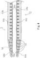
- FIG. 5is an enlarged view illustrating the vicinity of a distal end of a catheter 4 according to a fourth embodiment of the invention.
- the catheter 4 of the fourth embodimentis different from the catheter 3 of the above-described third embodiment in the following aspect. That is, the catheter 4 of the fourth embodiment includes, as a reinforcing body, a coil body 30c formed by winding metallic wires into a helical coil structure. Then, the metallic distal end tip 50 is welded to the distal end portion of the coil body 30c. In FIG. 5 , a welded portion w between the coil body 30c and the distal end tip 50 is illustrated by a bold wave line.
- the coil body 30cmay be formed by winding a single wire into a helical coil structure (a so-called single wound coil) or may be a hollow body formed by winding a plurality of wires into a helical coil structure (a so-called stranded wire coil).
- a stranded wire coilAs the rotation force of the catheter 4, it is preferable to use a stranded wire coil as the coil body 30c.
- the metallic material of the wires of the coil body 30cis not especially limited, and there can be used stainless steel (SUS304, SUS316, etc.), gold, white gold, tungsten, platinum, nickel, and an alloy of such elements, for example.
- the catheter 4 of the fourth embodimenthas the same structure as the catheter 3 of the above-described third embodiment. That is, a catheter shaft 14 has an inner layer 20c and an outer layer 40c. Moreover, the distal end tip 50 is provided with the slit 52. The outer peripheral surface of the distal end tip 50 is covered with outer coating 60c, and the inner surface thereof is covered with inner coating 70c.
- the reinforcing bodyis formed as the metallic coil body 30c, and the coil body 30c and the distal end tip 50 are welded to each other.
- the reinforcing bodyis formed as the metallic coil body 30c, and the coil body 30c and the distal end tip 50 are welded to each other.
- FIG. 6is an enlarged view illustrating the vicinity of a distal end of a catheter 5 according to a fifth embodiment of the invention.
- the catheter 5 of the fifth embodimentis different from the catheter 4 of the above-described fourth embodiment in the following aspect. That is, in the catheter 5 of the fifth embodiment, the distal end of a coil body 30d includes a part formed integrally by mutually-melted wires constituting the coil body 30d (a melted portion 32d), and the distal end tip 50 is welded to the melted portion 32d.
- the catheter 5 of the fifth embodimenthas the same structure as the catheters of the embodiments described above. That is, a catheter shaft 16 has an inner layer 20d and an outer layer 40d. Moreover, the distal end tip 50 is provided with the slit 52. The outer peripheral surface of the distal end tip 50 is covered with outer coating 60d and the inner surface thereof is covered with inner coating 70d.
- the wiresare melted mutually and formed integrally at the distal end portion of the coil body 30d, which regulates the movement of the wires at the distal end portion of the coil body 30d.
- a stranded wire coila hollow body formed by winding a plurality of wires into a helical coil structure
Landscapes
- Health & Medical Sciences (AREA)
- Life Sciences & Earth Sciences (AREA)
- Veterinary Medicine (AREA)
- Public Health (AREA)
- Engineering & Computer Science (AREA)
- General Health & Medical Sciences (AREA)
- Biomedical Technology (AREA)
- Heart & Thoracic Surgery (AREA)
- Animal Behavior & Ethology (AREA)
- Hematology (AREA)
- Anesthesiology (AREA)
- Pulmonology (AREA)
- Biophysics (AREA)
- Surgery (AREA)
- Vascular Medicine (AREA)
- Nuclear Medicine, Radiotherapy & Molecular Imaging (AREA)
- Medical Informatics (AREA)
- Molecular Biology (AREA)
- Media Introduction/Drainage Providing Device (AREA)
Description
- The present invention relates to a catheter capable of passing a hard lesion, for example.
- There is conventionally proposed a catheter including a metallic distal end tip (Japanese Unexamined Patent Application No.
2007-244492 - Moreover, there is proposed a catheter in which a resin distal end tip is provided with a groove so as to have flexibility (
U.S. Unexamined Patent Application No. 2008/0255507 , for example). - A slit is provided on a metallic distal end tip using the above-described conventional technique, whereby the distal end tip can be bent easily while the hardness thereof is maintained. This realizes a catheter being excellent in passing performance relative to a hard lesion, for example, and having favorable following properties for a tortuous blood vessel such as a peripheral blood vessel. Further, document
JP2001190680 (A JP2005230318 (A - However, when a slit is provided on the metallic distal end tip, unevenness occurs on the surface of the distal end tip, which causes a problem that the distal end tip is easily caught on a lesion, for example.
- The invention is defined as in the appended claims. In view of the above problem of the conventional technique, the present invention aims at allowing, in a catheter including a metallic distal end tip, the distal end tip to bend easily, and making it difficult for the distal end tip to be caught on a lesion, for example.
- In order to solve the problem described above, the catheter of the invention adopts the following structure. That is, the catheter includes a tube body constituted by an inner layer, a reinforcing body covering the inner layer, and an outer layer covering the reinforcing body, and a tubular metallic distal end tip provided at a distal end of the tube body, in which a slit is formed on the distal end tip and penetrates the distal end tip (50) from an outer peripheral surface of the distal end tip (50) to an inner surface of the distal end tip (50), and an outer peripheral surface of the distal end tip is provided with outer coating, and the outer coating enters the inside of the slit.
- In such a catheter of the invention, the metallic distal end tip is provided with the slit, thus allowing the distal end tip to bend easily. Moreover, an outer peripheral surface of the distal end tip is covered with outer coating, which smoothens the surface of the distal end tip and then makes it difficult for the distal end tip to be caught on a lesion, for example.
- In particular, the outer coating enters the inside of the slit to be firmly fixed to the distal end tip (an anchoring effect), which makes it possible to securely maintain the smooth surface of the distal end tip.
- The slit formed on the distal end tip may be formed helically around a longitudinal axis of the distal end tip. Further, a pitch of the slit may decrease toward a distal end of the distal end tip.
- Moreover, in the catheter of the invention, inner coating may be provided on an inner peripheral surface of the distal end tip, so that the outer coating entering the inside of the slit comes into contact with the inner coating.
- In such a catheter of the invention, the distal end tip is covered with outer coating and inner coating, and the outer coating entering the inside of the slit and the inner coating are in close contact with each other. Thus, the outer coating (and the inner coating) can be fixed to the distal end tip more firmly.
- Moreover, the inner coating can also smoothen the inner peripheral surface of the distal end tip, which also prevents the case in which a medical instrument (a guide wire, for example) passing a lumen of the catheter is caught on the inner peripheral surface of the distal end tip.
- Moreover, in the catheter of the invention described above, the outer coating and the outer layer of the tube body may be formed integrally, and the inner coating and the inner layer of the tube body may be formed integrally.
- In such a catheter of the invention, the outer coating and the outer layer of the tube layer are formed integrally, and the inner coating and the inner layer of the tube body are formed integrally, whereby a connection portion between the distal end tip and the tube body is coated seamlessly. This prevents occurrence of catch with the outside (a lesion, for example) and the inside (a guide wire passing a lumen of the catheter, for example) at the connection portion between the distal end tip and the tube body. At the same time, it is also possible to enhance connection strength between the distal end tip and the tube body.
- Moreover, in the catheter of the invention, a braid layer may be used as a reinforcing body.
- Alternatively, a coil body formed by winding at least one metallic wire into a helical coil structure may be used as a reinforcing body, and the distal end tip may be welded to the distal end of the coil body.
- In such a catheter of the invention, the coil body and the distal end tip are joined by welding. Thus, it is possible to further enhance connection strength between the distal end tip and the tube body.
- Further, in such a catheter the coil body may be formed by winding a single metallic wire or by winding a plurality of metallic wires.
- Furthermore, in the catheter of the invention, the distal end of the coil body as a reinforcing body may include a part formed integrally by mutually-melted wires constituting the coil body, and the metallic distal end tip may be welded to the part.
- In such a catheter of the invention, the wires are mutually melted and formed integrally at the distal end portion of the coil body, which regulates the movement of the wires at the distal end portion of the coil body. As a result, it is possible to easily weld the distal end tip and the distal end portion of the coil body.
FIG. 1 is an explanatory diagram illustrating a structure of a catheter according to a first embodiment of the invention;FIG. 2 is an enlarged view illustrating the vicinity of a distal end of the catheter (an area A inFIG. 1 ) according to the first embodiment of the invention, in which (a) illustrates a cross section illustrating the vicinity of the distal end of the catheter, and (b) illustrates an outer view of a distal end tip;FIG. 3 is an enlarged view illustrating the vicinity of a distal end of a catheter according to a second embodiment of the invention;FIG. 4 is an enlarged view illustrating the vicinity of a distal end of a catheter according to a third embodiment of the invention;FIG. 5 is an enlarged view illustrating the vicinity of a distal end of a catheter according to a fourth embodiment of the invention; andFIG. 6 is an enlarged view illustrating the vicinity of a distal end of a catheter according to a fifth embodiment of the invention.- In the following, various embodiments of the catheter of the invention will be described in order to clarify the subject matter of the above-described invention.
FIG. 1 is an explanatory diagram illustrating a structure of a catheter 1 according to a first embodiment of the invention. As illustrated inFIG. 1 , the catheter 1 of the first embodiment is constituted by acatheter shaft 10, aconnector 80 provided at the proximal end portion of thecatheter shaft 10, and adistal end tip 50 provided at the distal end portion of thecatheter shaft 10.- Note that the "catheter shaft" in the specification corresponds to the "tube body" of the invention.
FIG. 2 is an enlarged view illustrating the vicinity of a distal end of the catheter 1 (an area A inFIG. 1 ) according to the first embodiment of the invention. As illustrated inFIG. 2(a) , in the catheter 1 of the first embodiment, thecatheter shaft 10 is a tubular structural body, and is constituted by aninner layer 20a, abraid layer 30a covering theinner layer 20a, and anouter layer 40a covering thebraid layer 30a. Note that the "braid layer" in the specification is one form of the "reinforcing body" of the invention.- The
inner layer 20a is formed of resin. The resin material forming theinner layer 20a is not especially limited. However, considering slidability with an inserted instrument (a guide wire or a catheter, for example), polytetrafluoroethylene (PTFE) is preferable. - The
braid layer 30a is formed by braiding single wires. The material of the wires forming thebraid layer 30a is not especially limited, and there can be used stainless steel (SUS304, SUS316, etc.), gold, white gold, tungsten, platinum, nickel, and an alloy of such elements, for example. - The
outer layer 40a is formed of resin. The resin material forming theouter layer 40a is not especially limited, and there can be used polyamide, polyamide elastomer, polyester, and polyurethane, for example. - The metallic
distal end tip 50 is provided at the distal end portion of thecatheter shaft 10. Thedistal end tip 50 of the first embodiment is formed to be tapered in outer diameter toward the distal end. This improves passing performance relative to a hard lesion (a calcified lesion, for example). - Note that the metallic material used for the
distal end tip 50 is not especially limited, and there can be used stainless steel (SUS304, SUS316, etc.), gold, white gold, tungsten, platinum, nickel, and an alloy of such elements, for example. However, thedistal end tip 50 is preferably formed of radiopaque metallic material so that a position of the distal end of the catheter 1 can be grasped in a radioscopic image. - Moreover, the
distal end tip 50 of the first embodiment is provided with aslit 52. As it is seen fromFig. 2 theslit 52 penetrates thedistal end tip 50 from an outer peripheral surface of thedistal end tip 50 to an inner surface of thedistal end tip 50. Theslit 52 is provided to lighten the metallicdistal end tip 50 and thus improve flexibility thereof. - Note that as illustrated in
FIG. 2(b) , theslit 52 is formed helically on thedistal end tip 50 in the catheter 1 of the first embodiment. Thus, thedistal end tip 50 can be bent in any direction with a same level of easiness. Moreover, the pitch of theslit 52 is formed to be smaller toward the distal end, and the distal end area of thedistal end tip 50 is especially flexible. In this manner, it is possible to reduce the risk of perforation of a blood vessel by thedistal end tip 50. - Furthermore, as illustrated in
FIG. 2(a) , the outer peripheral surface of thedistal end tip 50 of the first embodiment is covered withouter coating 60a. Here, in the catheter 1 of the first embodiment, theouter coating 60a enters the inside of theslit 52 of thedistal end tip 50. - In such a catheter 1 of the first embodiment, the metallic
distal end tip 50 is provided with theslit 52, thus allowing thedistal end tip 50 to bend easily while the hardness thereof is maintained. Moreover, the outer peripheral surface of thedistal end tip 50 is covered with theouter coating 60a, which smooths the surface of thedistal end tip 50. As a result, it is possible to realize the catheter 1 being capable of passing a hard lesion easily, having favorable following properties for a tortuous blood vessel such as a peripheral blood vessel, and making it difficult for thedistal end tip 50 to be caught on a lesion, for example. - Particularly, in the catheter 1 of the first embodiment, the
outer coating 60a covering thedistal end tip 50 enters the inside of theslit 52 to be firmly fixed to thedistal end tip 50. Therefore, it is possible to prevent separation of theouter coating 60a from thedistal end tip 50 due to friction with the outside. Consequently, even when thedistal end tip 50 is made to pass a calcified lesion, for example, the smooth surface of thedistal end tip 50 can be securely maintained. FIG. 3 is an enlarged view illustrating the vicinity of a distal end of acatheter 2 according to a second embodiment of the invention. The illustratedcatheter 2 of the second embodiment is different from the catheter 1 of the above-described first embodiment in the following aspect. That is, theouter coating 60a is provided on the outer peripheral surface of thedistal end tip 50 and, in addition,inner coating 70a is provided on the inner surface of thedistal end tip 50. Then, theouter coating 60a entering the inside of theslit 52 of thedistal end tip 50 reaches theinner coating 70a, so that theouter coating 60a and theinner coating 70a are in close contact with each other.- Regarding aspects other than the above, the catheter 1 of the first embodiment and the
catheter 2 of the second embodiment have the same structure. That is, thecatheter shaft 10 is constituted by theinner layer 20a, thebraid layer 30a covering theinner layer 20a, and theouter layer 40a covering thebraid layer 30a. - Also in such a
catheter 2 of the second embodiment, it is possible to maintain easiness in bending of the metallicdistal end tip 50 and prevent the case in which thedistal end tip 50 is caught on a lesion, for example, similarly to the catheter 1 of the above-mentioned first embodiment. - Moreover, in the
catheter 2 of the second embodiment, thedistal end tip 50 is covered with theouter coating 60a and theinner coating 70a, and theouter coating 60a entering the inside of theslit 52 and theinner coating 70a come in contact with each other. Thus, theouter coating 60a (and theinner coating 70a) can be fixed to thedistal end tip 50 more firmly. - Furthermore, the
inner coating 70a can also smoothen the inner surface of thedistal end tip 50, which also prevents the case in which a medical instrument (a guide wire, for example) passing a lumen of thecatheter 2 is caught on the inner peripheral surface of thedistal end tip 50. FIG. 4 is an enlarged view illustrating the vicinity of a distal end of a catheter 3 according to a third embodiment of the invention. The catheter 3 of the third embodiment is different from thecatheter 2 of the above-described second embodiment in the following aspect. That is, in the catheter 3 of the third embodiment, anouter layer 40b of acatheter shaft 12 andouter coating 60b covering the outer peripheral surface of thedistal end tip 50 are formed integrally, and aninner layer 20b of thecatheter shaft 12 andinner coating 70b covering the inner surface of thedistal end tip 50 are formed integrally.- Regarding aspects other than the above, the catheter 3 of the third embodiment has the same structure as the
catheter 2 of the above-described second embodiment. That is, thecatheter shaft 12 is provided with abraid layer 30b covering theinner layer 20b, and thedistal end tip 50 is provided with theslit 52. - Also in such a catheter 3 of the third embodiment, it is possible to maintain easiness in bending of the metallic
distal end tip 50 and prevent the case in which thedistal end tip 50 is caught on a lesion, for example, similarly to the catheters of the various embodiments described above. - Moreover, in the catheter 3 of the third embodiment, the
outer coating 60b and theouter layer 40b are formed integrally, and theinner coating 70b and theinner layer 20b are formed integrally, whereby the connection portion between thedistal end tip 50 and thecatheter shaft 12 is coated seamlessly. This prevents occurrence of catch with the outside (a lesion, for example) and the inside (a guide wire passing a lumen of the catheter, for example) at the connection portion between thedistal end tip 50 and thecatheter shaft 12. At the same time, it is also possible to enhance connection strength between thedistal end tip 50 and thecatheter shaft 12. FIG. 5 is an enlarged view illustrating the vicinity of a distal end of acatheter 4 according to a fourth embodiment of the invention. Thecatheter 4 of the fourth embodiment is different from the catheter 3 of the above-described third embodiment in the following aspect. That is, thecatheter 4 of the fourth embodiment includes, as a reinforcing body, acoil body 30c formed by winding metallic wires into a helical coil structure. Then, the metallicdistal end tip 50 is welded to the distal end portion of thecoil body 30c. InFIG. 5 , a welded portion w between thecoil body 30c and thedistal end tip 50 is illustrated by a bold wave line.- Note that the
coil body 30c may be formed by winding a single wire into a helical coil structure (a so-called single wound coil) or may be a hollow body formed by winding a plurality of wires into a helical coil structure (a so-called stranded wire coil). Considering the rotation force of thecatheter 4, it is preferable to use a stranded wire coil as thecoil body 30c. Moreover, the metallic material of the wires of thecoil body 30c is not especially limited, and there can be used stainless steel (SUS304, SUS316, etc.), gold, white gold, tungsten, platinum, nickel, and an alloy of such elements, for example. - Regarding aspects other than the above, the
catheter 4 of the fourth embodiment has the same structure as the catheter 3 of the above-described third embodiment. That is, acatheter shaft 14 has aninner layer 20c and an outer layer 40c. Moreover, thedistal end tip 50 is provided with theslit 52. The outer peripheral surface of thedistal end tip 50 is covered with outer coating 60c, and the inner surface thereof is covered with inner coating 70c. - Also in such a
catheter 4 of the fourth embodiment, it is possible to maintain easiness in bending of the metallicdistal end tip 50 and prevent the case in which thedistal end tip 50 is caught on a lesion, for example, similarly to the catheters of the various embodiments described above. - Moreover, in the
catheter 4 of the fourth embodiment, the reinforcing body is formed as themetallic coil body 30c, and thecoil body 30c and thedistal end tip 50 are welded to each other. Thus, it is possible to further enhance connection strength between thedistal end tip 50 and thecatheter shaft 14. FIG. 6 is an enlarged view illustrating the vicinity of a distal end of a catheter 5 according to a fifth embodiment of the invention. The catheter 5 of the fifth embodiment is different from thecatheter 4 of the above-described fourth embodiment in the following aspect. That is, in the catheter 5 of the fifth embodiment, the distal end of acoil body 30d includes a part formed integrally by mutually-melted wires constituting thecoil body 30d (a meltedportion 32d), and thedistal end tip 50 is welded to the meltedportion 32d.- Regarding aspects other than the above, the catheter 5 of the fifth embodiment has the same structure as the catheters of the embodiments described above. That is, a
catheter shaft 16 has aninner layer 20d and anouter layer 40d. Moreover, thedistal end tip 50 is provided with theslit 52. The outer peripheral surface of thedistal end tip 50 is covered withouter coating 60d and the inner surface thereof is covered with inner coating 70d. - Also in such a catheter 5 of the fifth embodiment, it is possible to maintain easiness in bending of the metallic
distal end tip 50 and prevent the case in which thedistal end tip 50 is caught on a lesion, for example, similarly to the catheters of the various embodiments described above. - Moreover, in the catheter 5 of the fifth embodiment, the wires are melted mutually and formed integrally at the distal end portion of the
coil body 30d, which regulates the movement of the wires at the distal end portion of thecoil body 30d. For example, when a stranded wire coil (a hollow body formed by winding a plurality of wires into a helical coil structure) is used as thecoil body 30d, it is possible to prevent loosening of the end portion of the stranded wire coil. As a result, it is possible to easily join thedistal end tip 50 and the distal end portion of thecoil body 30d.
Claims (10)
- A catheter (1; 2; 3; 4; 5) comprising:a tube body (10) including an inner layer (20a), a reinforcing body (30a; 30b; 30c; 30d) covering the inner layer (20a), and an outer layer (40a) covering the reinforcing body (30a; 30b; 30c; 30d); anda tubular metallic distal end tip (50) provided at a distal end of the tube body (10),characterized in thata slit (52) is formed on the distal end tip (50) and penetrates the distal end tip (50) from an outer peripheral surface of the distal end tip (50) to an inner surface of the distal end tip (50), andan outer peripheral surface of the distal end tip (50) is provided with an outer coating (60a), and the outer coating (60a) enters inside of the slit (52).
- The catheter (2; 3) according to claim 1, wherein
an inner peripheral surface of the distal end tip (50) is provided with an inner coating (70a), and
the outer coating (60a) entering the inside of the slit (52) and the inner coating (70a) come in contact with each other. - The catheter (3) according to claim 2, wherein
the outer coating (60a) and the outer layer (40a) of the tube body (10) are formed integrally, and the inner coating (70a) and the inner layer (20a) of the tube body (10) are formed integrally. - The catheter (1; 2; 3) according to any one of claims 1 to 3, wherein
the reinforcing body (30a; 30b) is a braid layer. - The catheter (4; 5) according to any one of claims 1 to 3, wherein
the reinforcing body (30c; 30d) is a coil body formed by winding at least one metallic wire into a helical coil structure, and
the distal end tip (50) is welded to a distal end of the coil body (30c; 30d). - The catheter (4, 5) according to claim 5, wherein
the coil body (30c; 30d) is formed by winding a single metallic wire. - The catheter (4, 5) according to claim 5, wherein
the coil body (30c; 30d) is formed by winding a plurality of metallic wires. - The catheter (5) according to claim 7, wherein
the distal end of the coil body (30d) includes a part (32d) formed integrally by mutually-melted wires constituting the coil body (30d), and the metallic distal end tip (50) is welded to the part (32d). - The catheter (1; 2; 3; 4; 5) according to any one of claims 1 to 8, wherein
the slit (52) formed on the distal end tip (50) is formed helically. - The catheter (1; 2; 3; 4; 5) according to claim 9, wherein
a pitch of the slit (52) decreases toward a distal end of the distal end tip (50).
Applications Claiming Priority (1)
| Application Number | Priority Date | Filing Date | Title |
|---|---|---|---|
| JP2014090784AJP5954748B2 (en) | 2014-04-25 | 2014-04-25 | catheter |
Publications (2)
| Publication Number | Publication Date |
|---|---|
| EP2937108A1 EP2937108A1 (en) | 2015-10-28 |
| EP2937108B1true EP2937108B1 (en) | 2019-03-13 |
Family
ID=52780953
Family Applications (1)
| Application Number | Title | Priority Date | Filing Date |
|---|---|---|---|
| EP15161844.4AActiveEP2937108B1 (en) | 2014-04-25 | 2015-03-31 | Catheter |
Country Status (4)
| Country | Link |
|---|---|
| US (1) | US10166363B2 (en) |
| EP (1) | EP2937108B1 (en) |
| JP (1) | JP5954748B2 (en) |
| CN (1) | CN105013061B (en) |
Cited By (2)
| Publication number | Priority date | Publication date | Assignee | Title |
|---|---|---|---|---|
| US11850349B2 (en) | 2018-07-06 | 2023-12-26 | Incept, Llc | Vacuum transfer tool for extendable catheter |
| WO2025176333A1 (en) | 2024-02-23 | 2025-08-28 | Cti Vascular Ag | Crossing balloon catheter |
Families Citing this family (56)
| Publication number | Priority date | Publication date | Assignee | Title |
|---|---|---|---|---|
| EP1907042B1 (en) | 2005-07-06 | 2009-03-11 | Vascular Pathways Inc. | Intravenous catheter insertion device and method of use |
| EP2150304B1 (en) | 2007-05-07 | 2010-12-01 | Vascular Pathways Inc. | Intravenous catheter insertion and blood sample devices and method of use |
| US9872971B2 (en) | 2010-05-14 | 2018-01-23 | C. R. Bard, Inc. | Guidewire extension system for a catheter placement device |
| US8932258B2 (en) | 2010-05-14 | 2015-01-13 | C. R. Bard, Inc. | Catheter placement device and method |
| US9950139B2 (en) | 2010-05-14 | 2018-04-24 | C. R. Bard, Inc. | Catheter placement device including guidewire and catheter control elements |
| US10384039B2 (en) | 2010-05-14 | 2019-08-20 | C. R. Bard, Inc. | Catheter insertion device including top-mounted advancement components |
| US11925779B2 (en) | 2010-05-14 | 2024-03-12 | C. R. Bard, Inc. | Catheter insertion device including top-mounted advancement components |
| US8690833B2 (en) | 2011-01-31 | 2014-04-08 | Vascular Pathways, Inc. | Intravenous catheter and insertion device with reduced blood spatter |
| ES2835652T3 (en) | 2011-02-25 | 2021-06-22 | Bard Inc C R | Medical component insertion device including a retractable needle |
| USD903101S1 (en) | 2011-05-13 | 2020-11-24 | C. R. Bard, Inc. | Catheter |
| WO2014120741A1 (en) | 2013-01-30 | 2014-08-07 | Vascular Pathways, Inc. | Systems and methods for venipuncture and catheter placement |
| WO2016037127A1 (en) | 2014-09-05 | 2016-03-10 | C.R. Bard, Inc. | Catheter insertion device including retractable needle |
| JP2016101194A (en)* | 2014-11-27 | 2016-06-02 | 朝日インテック株式会社 | catheter |
| EP3072549A1 (en)* | 2015-03-23 | 2016-09-28 | Asahi Intecc Co., Ltd. | Catheter |
| USD903100S1 (en) | 2015-05-01 | 2020-11-24 | C. R. Bard, Inc. | Catheter placement device |
| CN113350614A (en) | 2015-05-15 | 2021-09-07 | C·R·巴德股份有限公司 | Catheter placement device including extendable needle safety feature |
| WO2017147493A1 (en) | 2016-02-24 | 2017-08-31 | Incept, Llc | Enhanced flexibility neurovascular catheter |
| US20200077991A1 (en)* | 2016-05-31 | 2020-03-12 | Intuitive Surgical Operations, Inc. | Pliant biopsy needle system |
| EP4032578A1 (en) | 2016-07-13 | 2022-07-27 | Perfuze Limited | High flexibility, kink resistant catheter shaft |
| JP6319777B1 (en)* | 2016-09-05 | 2018-05-09 | 朝日インテック株式会社 | Guide wire |
| US10493262B2 (en) | 2016-09-12 | 2019-12-03 | C. R. Bard, Inc. | Blood control for a catheter insertion device |
| US20180085555A1 (en)* | 2016-09-26 | 2018-03-29 | Boston Scientific Scimed, Inc. | Injection catheter |
| JP6241907B1 (en)* | 2016-10-04 | 2017-12-06 | 朝日インテック株式会社 | Catheter and balloon catheter |
| JP7264581B2 (en) | 2017-01-06 | 2023-04-25 | インセプト、リミテッド、ライアビリティ、カンパニー | Antithrombotic coating for aneurysm treatment devices |
| EP3585471B1 (en) | 2017-03-01 | 2025-01-01 | C. R. Bard, Inc. | Catheter insertion device |
| EP3593848B1 (en)* | 2017-03-10 | 2022-04-20 | Asahi Intecc Co., Ltd. | Catheter |
| EP3597258B1 (en) | 2017-03-16 | 2025-09-03 | Terumo Kabushiki Kaisha | Catheter assembly |
| JP2018201765A (en)* | 2017-06-01 | 2018-12-27 | オリンパス株式会社 | Tube for medical equipment |
| JP6952776B2 (en)* | 2017-06-29 | 2021-10-20 | 朝日インテック株式会社 | catheter |
| CN110545741A (en)* | 2017-08-24 | 2019-12-06 | 株式会社钟化 | Basket catheter, method for producing the same, and medical treatment instrument |
| EP3476423B1 (en)* | 2017-10-27 | 2021-01-20 | Heraeus Medical Components, LLC | Microcatheter and method |
| US10668247B2 (en)* | 2017-11-15 | 2020-06-02 | Alcyone Lifesciences, Inc. | Therapy specific, pre-programmed auto injection device |
| CN111465420B (en) | 2017-12-15 | 2023-04-18 | 佩尔福兹有限公司 | Improved catheter and apparatus and system incorporating same |
| WO2019146026A1 (en)* | 2018-01-25 | 2019-08-01 | 朝日インテック株式会社 | Catheter |
| WO2019146086A1 (en) | 2018-01-26 | 2019-08-01 | 朝日インテック株式会社 | Catheter |
| KR20200108039A (en) | 2018-01-26 | 2020-09-16 | 아사히 인텍크 가부시키가이샤 | Catheter |
| ES2980192T3 (en) | 2018-03-07 | 2024-09-30 | Bard Access Systems Inc | Guidewire advancement and blood reflux systems for a medical device insertion system |
| JP7265527B2 (en) | 2018-03-29 | 2023-04-26 | テルモ株式会社 | catheter assembly |
| AU2019262972B2 (en)* | 2018-05-01 | 2025-02-27 | Incept, Llc | Devices and methods for removing obstructive material from an intravascular site |
| US11395665B2 (en) | 2018-05-01 | 2022-07-26 | Incept, Llc | Devices and methods for removing obstructive material, from an intravascular site |
| US11517335B2 (en) | 2018-07-06 | 2022-12-06 | Incept, Llc | Sealed neurovascular extendable catheter |
| USD921884S1 (en) | 2018-07-27 | 2021-06-08 | Bard Access Systems, Inc. | Catheter insertion device |
| US11766539B2 (en) | 2019-03-29 | 2023-09-26 | Incept, Llc | Enhanced flexibility neurovascular catheter |
| CA3151126A1 (en) | 2019-08-19 | 2021-02-25 | Becton, Dickinson And Company | Midline catheter placement device |
| US11134859B2 (en) | 2019-10-15 | 2021-10-05 | Imperative Care, Inc. | Systems and methods for multivariate stroke detection |
| US11638637B2 (en) | 2019-12-18 | 2023-05-02 | Imperative Care, Inc. | Method of removing embolic material with thrombus engagement tool |
| EP4076611A4 (en) | 2019-12-18 | 2023-11-15 | Imperative Care, Inc. | Methods and systems for treating venous thromboembolic disease |
| US20210316127A1 (en) | 2019-12-18 | 2021-10-14 | Imperative Care, Inc. | Hemostasis valve |
| US20230248502A1 (en) | 2019-12-18 | 2023-08-10 | Imperative Care, Inc. | Sterile field clot capture module for use in thrombectomy system |
| CN113747934B (en) | 2020-03-10 | 2024-07-09 | 因普瑞缇夫护理公司 | Enhanced flexibility neurovascular catheter |
| CN115734797A (en)* | 2020-07-06 | 2023-03-03 | 朝日英达科株式会社 | catheter |
| EP4243708A4 (en)* | 2020-11-13 | 2024-09-18 | Microvention, Inc. | Distal aspiration catheter and method |
| US20230052862A1 (en) | 2021-08-12 | 2023-02-16 | Imperative Care, Inc. | Sterile packaging assembly for robotic interventional device |
| USD1077996S1 (en) | 2021-10-18 | 2025-06-03 | Imperative Care, Inc. | Inline fluid filter |
| WO2024236627A1 (en)* | 2023-05-12 | 2024-11-21 | 朝日インテック株式会社 | Medical device |
| US12171917B1 (en) | 2024-01-08 | 2024-12-24 | Imperative Care, Inc. | Devices for blood capture and reintroduction during aspiration procedure |
Family Cites Families (16)
| Publication number | Priority date | Publication date | Assignee | Title |
|---|---|---|---|---|
| JPH04338546A (en)* | 1991-05-15 | 1992-11-25 | Fujitsu Ltd | inkjet head |
| JPH07178176A (en)* | 1993-12-24 | 1995-07-18 | Terumo Corp | Catheter |
| US5496294A (en)* | 1994-07-08 | 1996-03-05 | Target Therapeutics, Inc. | Catheter with kink-resistant distal tip |
| JPH08308933A (en)* | 1995-05-22 | 1996-11-26 | Piolax Inc | Medical tube |
| US7815626B1 (en)* | 1998-06-12 | 2010-10-19 | Target Therapeutics, Inc. | Catheter with knit section |
| JP4301670B2 (en)* | 2000-01-12 | 2009-07-22 | テルモ株式会社 | Medical tube |
| JP4338546B2 (en)* | 2004-02-20 | 2009-10-07 | ミヤチテクノス株式会社 | Catheter processing method |
| JP2007244492A (en) | 2006-03-14 | 2007-09-27 | Yokohama Tlo Co Ltd | Intraosseous catheter |
| US7608085B2 (en)* | 2006-05-16 | 2009-10-27 | Joel Kwan Barrientos | Catheter having end including grooved needle guides |
| US20080255507A1 (en)* | 2006-06-15 | 2008-10-16 | Medtronic Vascular, Inc. | Catheter Assembly Having a Grooved Distal Tip |
| JP2011512956A (en)* | 2008-02-26 | 2011-04-28 | ボストン サイエンティフィック サイムド,インコーポレイテッド | Balloon catheter with a highly durable tip |
| US8206373B2 (en)* | 2008-07-01 | 2012-06-26 | Boston Scientific Scimed, Inc. | Medical device including braid with coated portion |
| EP2311518B1 (en)* | 2008-08-11 | 2013-06-26 | Terumo Kabushiki Kaisha | Medical instrument |
| JP4743800B2 (en)* | 2008-10-11 | 2011-08-10 | 朝日インテック株式会社 | catheter |
| WO2012109468A1 (en)* | 2011-02-09 | 2012-08-16 | Boston Scientific Scimed, Inc. | Balloon catheter |
| CN104707235A (en)* | 2013-12-17 | 2015-06-17 | 常州乐奥医疗科技有限公司 | Novel micro-catheter |
- 2014
- 2014-04-25JPJP2014090784Apatent/JP5954748B2/enactiveActive
- 2015
- 2015-02-26CNCN201510088648.3Apatent/CN105013061B/enactiveActive
- 2015-03-31EPEP15161844.4Apatent/EP2937108B1/enactiveActive
- 2015-04-23USUS14/694,426patent/US10166363B2/enactiveActive
Non-Patent Citations (1)
| Title |
|---|
| None* |
Cited By (2)
| Publication number | Priority date | Publication date | Assignee | Title |
|---|---|---|---|---|
| US11850349B2 (en) | 2018-07-06 | 2023-12-26 | Incept, Llc | Vacuum transfer tool for extendable catheter |
| WO2025176333A1 (en) | 2024-02-23 | 2025-08-28 | Cti Vascular Ag | Crossing balloon catheter |
Also Published As
| Publication number | Publication date |
|---|---|
| JP2015208425A (en) | 2015-11-24 |
| CN105013061A (en) | 2015-11-04 |
| EP2937108A1 (en) | 2015-10-28 |
| US20150306347A1 (en) | 2015-10-29 |
| US10166363B2 (en) | 2019-01-01 |
| CN105013061B (en) | 2019-06-07 |
| JP5954748B2 (en) | 2016-07-20 |
Similar Documents
| Publication | Publication Date | Title |
|---|---|---|
| EP2937108B1 (en) | Catheter | |
| EP2949358B1 (en) | Catheter | |
| EP2923724B1 (en) | Catheter | |
| JP4743800B2 (en) | catheter | |
| WO2013100045A1 (en) | Guide wire | |
| JP6558773B2 (en) | catheter | |
| JP6426068B2 (en) | Catheter and balloon catheter | |
| US20220054802A1 (en) | Guide wire | |
| JP7119132B2 (en) | CATHETER AND CATHETER MANUFACTURING METHOD | |
| US11484687B2 (en) | Catheter | |
| US11027094B2 (en) | Tubular body and catheter having tubular body | |
| JPWO2018163401A1 (en) | catheter | |
| EP4176918A1 (en) | Catheter | |
| CN112423825A (en) | Guide wire | |
| JP6850368B2 (en) | catheter | |
| JP2024162903A (en) | Medical Devices | |
| JP2024027763A (en) | Medical long body | |
| WO2024038595A1 (en) | Elongated body for medical use and catheter | |
| JP2019198662A (en) | catheter |
Legal Events
| Date | Code | Title | Description |
|---|---|---|---|
| PUAI | Public reference made under article 153(3) epc to a published international application that has entered the european phase | Free format text:ORIGINAL CODE: 0009012 | |
| AK | Designated contracting states | Kind code of ref document:A1 Designated state(s):AL AT BE BG CH CY CZ DE DK EE ES FI FR GB GR HR HU IE IS IT LI LT LU LV MC MK MT NL NO PL PT RO RS SE SI SK SM TR | |
| AX | Request for extension of the european patent | Extension state:BA ME | |
| 17P | Request for examination filed | Effective date:20160411 | |
| RBV | Designated contracting states (corrected) | Designated state(s):AL AT BE BG CH CY CZ DE DK EE ES FI FR GB GR HR HU IE IS IT LI LT LU LV MC MK MT NL NO PL PT RO RS SE SI SK SM TR | |
| REG | Reference to a national code | Ref country code:DE Ref legal event code:R079 Ref document number:602015026161 Country of ref document:DE Free format text:PREVIOUS MAIN CLASS: A61M0025000000 Ipc:A61M0025010000 | |
| GRAP | Despatch of communication of intention to grant a patent | Free format text:ORIGINAL CODE: EPIDOSNIGR1 | |
| STAA | Information on the status of an ep patent application or granted ep patent | Free format text:STATUS: GRANT OF PATENT IS INTENDED | |
| RIC1 | Information provided on ipc code assigned before grant | Ipc:A61M 25/01 20060101AFI20180912BHEP Ipc:A61M 25/10 20130101ALI20180912BHEP Ipc:A61M 25/00 20060101ALI20180912BHEP | |
| INTG | Intention to grant announced | Effective date:20181005 | |
| RAP1 | Party data changed (applicant data changed or rights of an application transferred) | Owner name:ASAHI INTECC CO., LTD. | |
| GRAS | Grant fee paid | Free format text:ORIGINAL CODE: EPIDOSNIGR3 | |
| GRAA | (expected) grant | Free format text:ORIGINAL CODE: 0009210 | |
| STAA | Information on the status of an ep patent application or granted ep patent | Free format text:STATUS: THE PATENT HAS BEEN GRANTED | |
| RIN1 | Information on inventor provided before grant (corrected) | Inventor name:YAGI, TAKAYUKI | |
| AK | Designated contracting states | Kind code of ref document:B1 Designated state(s):AL AT BE BG CH CY CZ DE DK EE ES FI FR GB GR HR HU IE IS IT LI LT LU LV MC MK MT NL NO PL PT RO RS SE SI SK SM TR | |
| REG | Reference to a national code | Ref country code:GB Ref legal event code:FG4D | |
| REG | Reference to a national code | Ref country code:CH Ref legal event code:EP Ref country code:AT Ref legal event code:REF Ref document number:1106857 Country of ref document:AT Kind code of ref document:T Effective date:20190315 | |
| REG | Reference to a national code | Ref country code:IE Ref legal event code:FG4D | |
| REG | Reference to a national code | Ref country code:DE Ref legal event code:R096 Ref document number:602015026161 Country of ref document:DE | |
| REG | Reference to a national code | Ref country code:NL Ref legal event code:MP Effective date:20190313 | |
| REG | Reference to a national code | Ref country code:LT Ref legal event code:MG4D | |
| PG25 | Lapsed in a contracting state [announced via postgrant information from national office to epo] | Ref country code:SE Free format text:LAPSE BECAUSE OF FAILURE TO SUBMIT A TRANSLATION OF THE DESCRIPTION OR TO PAY THE FEE WITHIN THE PRESCRIBED TIME-LIMIT Effective date:20190313 Ref country code:NO Free format text:LAPSE BECAUSE OF FAILURE TO SUBMIT A TRANSLATION OF THE DESCRIPTION OR TO PAY THE FEE WITHIN THE PRESCRIBED TIME-LIMIT Effective date:20190613 Ref country code:FI Free format text:LAPSE BECAUSE OF FAILURE TO SUBMIT A TRANSLATION OF THE DESCRIPTION OR TO PAY THE FEE WITHIN THE PRESCRIBED TIME-LIMIT Effective date:20190313 Ref country code:LT Free format text:LAPSE BECAUSE OF FAILURE TO SUBMIT A TRANSLATION OF THE DESCRIPTION OR TO PAY THE FEE WITHIN THE PRESCRIBED TIME-LIMIT Effective date:20190313 | |
| PG25 | Lapsed in a contracting state [announced via postgrant information from national office to epo] | Ref country code:BG Free format text:LAPSE BECAUSE OF FAILURE TO SUBMIT A TRANSLATION OF THE DESCRIPTION OR TO PAY THE FEE WITHIN THE PRESCRIBED TIME-LIMIT Effective date:20190613 Ref country code:NL Free format text:LAPSE BECAUSE OF FAILURE TO SUBMIT A TRANSLATION OF THE DESCRIPTION OR TO PAY THE FEE WITHIN THE PRESCRIBED TIME-LIMIT Effective date:20190313 Ref country code:HR Free format text:LAPSE BECAUSE OF FAILURE TO SUBMIT A TRANSLATION OF THE DESCRIPTION OR TO PAY THE FEE WITHIN THE PRESCRIBED TIME-LIMIT Effective date:20190313 Ref country code:RS Free format text:LAPSE BECAUSE OF FAILURE TO SUBMIT A TRANSLATION OF THE DESCRIPTION OR TO PAY THE FEE WITHIN THE PRESCRIBED TIME-LIMIT Effective date:20190313 Ref country code:GR Free format text:LAPSE BECAUSE OF FAILURE TO SUBMIT A TRANSLATION OF THE DESCRIPTION OR TO PAY THE FEE WITHIN THE PRESCRIBED TIME-LIMIT Effective date:20190614 Ref country code:LV Free format text:LAPSE BECAUSE OF FAILURE TO SUBMIT A TRANSLATION OF THE DESCRIPTION OR TO PAY THE FEE WITHIN THE PRESCRIBED TIME-LIMIT Effective date:20190313 | |
| REG | Reference to a national code | Ref country code:AT Ref legal event code:MK05 Ref document number:1106857 Country of ref document:AT Kind code of ref document:T Effective date:20190313 | |
| PG25 | Lapsed in a contracting state [announced via postgrant information from national office to epo] | Ref country code:CZ Free format text:LAPSE BECAUSE OF FAILURE TO SUBMIT A TRANSLATION OF THE DESCRIPTION OR TO PAY THE FEE WITHIN THE PRESCRIBED TIME-LIMIT Effective date:20190313 Ref country code:AL Free format text:LAPSE BECAUSE OF FAILURE TO SUBMIT A TRANSLATION OF THE DESCRIPTION OR TO PAY THE FEE WITHIN THE PRESCRIBED TIME-LIMIT Effective date:20190313 Ref country code:RO Free format text:LAPSE BECAUSE OF FAILURE TO SUBMIT A TRANSLATION OF THE DESCRIPTION OR TO PAY THE FEE WITHIN THE PRESCRIBED TIME-LIMIT Effective date:20190313 Ref country code:PT Free format text:LAPSE BECAUSE OF FAILURE TO SUBMIT A TRANSLATION OF THE DESCRIPTION OR TO PAY THE FEE WITHIN THE PRESCRIBED TIME-LIMIT Effective date:20190713 Ref country code:SK Free format text:LAPSE BECAUSE OF FAILURE TO SUBMIT A TRANSLATION OF THE DESCRIPTION OR TO PAY THE FEE WITHIN THE PRESCRIBED TIME-LIMIT Effective date:20190313 Ref country code:IT Free format text:LAPSE BECAUSE OF FAILURE TO SUBMIT A TRANSLATION OF THE DESCRIPTION OR TO PAY THE FEE WITHIN THE PRESCRIBED TIME-LIMIT Effective date:20190313 Ref country code:EE Free format text:LAPSE BECAUSE OF FAILURE TO SUBMIT A TRANSLATION OF THE DESCRIPTION OR TO PAY THE FEE WITHIN THE PRESCRIBED TIME-LIMIT Effective date:20190313 Ref country code:ES Free format text:LAPSE BECAUSE OF FAILURE TO SUBMIT A TRANSLATION OF THE DESCRIPTION OR TO PAY THE FEE WITHIN THE PRESCRIBED TIME-LIMIT Effective date:20190313 | |
| REG | Reference to a national code | Ref country code:CH Ref legal event code:PL | |
| PG25 | Lapsed in a contracting state [announced via postgrant information from national office to epo] | Ref country code:SM Free format text:LAPSE BECAUSE OF FAILURE TO SUBMIT A TRANSLATION OF THE DESCRIPTION OR TO PAY THE FEE WITHIN THE PRESCRIBED TIME-LIMIT Effective date:20190313 Ref country code:PL Free format text:LAPSE BECAUSE OF FAILURE TO SUBMIT A TRANSLATION OF THE DESCRIPTION OR TO PAY THE FEE WITHIN THE PRESCRIBED TIME-LIMIT Effective date:20190313 Ref country code:LU Free format text:LAPSE BECAUSE OF NON-PAYMENT OF DUE FEES Effective date:20190331 | |
| REG | Reference to a national code | Ref country code:BE Ref legal event code:MM Effective date:20190331 | |
| REG | Reference to a national code | Ref country code:DE Ref legal event code:R097 Ref document number:602015026161 Country of ref document:DE | |
| PG25 | Lapsed in a contracting state [announced via postgrant information from national office to epo] | Ref country code:IS Free format text:LAPSE BECAUSE OF FAILURE TO SUBMIT A TRANSLATION OF THE DESCRIPTION OR TO PAY THE FEE WITHIN THE PRESCRIBED TIME-LIMIT Effective date:20190713 Ref country code:AT Free format text:LAPSE BECAUSE OF FAILURE TO SUBMIT A TRANSLATION OF THE DESCRIPTION OR TO PAY THE FEE WITHIN THE PRESCRIBED TIME-LIMIT Effective date:20190313 | |
| PLBE | No opposition filed within time limit | Free format text:ORIGINAL CODE: 0009261 | |
| STAA | Information on the status of an ep patent application or granted ep patent | Free format text:STATUS: NO OPPOSITION FILED WITHIN TIME LIMIT | |
| PG25 | Lapsed in a contracting state [announced via postgrant information from national office to epo] | Ref country code:LI Free format text:LAPSE BECAUSE OF NON-PAYMENT OF DUE FEES Effective date:20190331 Ref country code:IE Free format text:LAPSE BECAUSE OF NON-PAYMENT OF DUE FEES Effective date:20190331 Ref country code:DK Free format text:LAPSE BECAUSE OF FAILURE TO SUBMIT A TRANSLATION OF THE DESCRIPTION OR TO PAY THE FEE WITHIN THE PRESCRIBED TIME-LIMIT Effective date:20190313 Ref country code:MC Free format text:LAPSE BECAUSE OF FAILURE TO SUBMIT A TRANSLATION OF THE DESCRIPTION OR TO PAY THE FEE WITHIN THE PRESCRIBED TIME-LIMIT Effective date:20190313 Ref country code:CH Free format text:LAPSE BECAUSE OF NON-PAYMENT OF DUE FEES Effective date:20190331 | |
| 26N | No opposition filed | Effective date:20191216 | |
| PG25 | Lapsed in a contracting state [announced via postgrant information from national office to epo] | Ref country code:SI Free format text:LAPSE BECAUSE OF FAILURE TO SUBMIT A TRANSLATION OF THE DESCRIPTION OR TO PAY THE FEE WITHIN THE PRESCRIBED TIME-LIMIT Effective date:20190313 Ref country code:BE Free format text:LAPSE BECAUSE OF NON-PAYMENT OF DUE FEES Effective date:20190331 | |
| PG25 | Lapsed in a contracting state [announced via postgrant information from national office to epo] | Ref country code:TR Free format text:LAPSE BECAUSE OF FAILURE TO SUBMIT A TRANSLATION OF THE DESCRIPTION OR TO PAY THE FEE WITHIN THE PRESCRIBED TIME-LIMIT Effective date:20190313 | |
| PG25 | Lapsed in a contracting state [announced via postgrant information from national office to epo] | Ref country code:MT Free format text:LAPSE BECAUSE OF NON-PAYMENT OF DUE FEES Effective date:20190331 | |
| PG25 | Lapsed in a contracting state [announced via postgrant information from national office to epo] | Ref country code:CY Free format text:LAPSE BECAUSE OF FAILURE TO SUBMIT A TRANSLATION OF THE DESCRIPTION OR TO PAY THE FEE WITHIN THE PRESCRIBED TIME-LIMIT Effective date:20190313 | |
| PG25 | Lapsed in a contracting state [announced via postgrant information from national office to epo] | Ref country code:HU Free format text:LAPSE BECAUSE OF FAILURE TO SUBMIT A TRANSLATION OF THE DESCRIPTION OR TO PAY THE FEE WITHIN THE PRESCRIBED TIME-LIMIT; INVALID AB INITIO Effective date:20150331 | |
| PG25 | Lapsed in a contracting state [announced via postgrant information from national office to epo] | Ref country code:MK Free format text:LAPSE BECAUSE OF FAILURE TO SUBMIT A TRANSLATION OF THE DESCRIPTION OR TO PAY THE FEE WITHIN THE PRESCRIBED TIME-LIMIT Effective date:20190313 | |
| PGFP | Annual fee paid to national office [announced via postgrant information from national office to epo] | Ref country code:DE Payment date:20250319 Year of fee payment:11 | |
| PGFP | Annual fee paid to national office [announced via postgrant information from national office to epo] | Ref country code:FR Payment date:20250325 Year of fee payment:11 | |
| PGFP | Annual fee paid to national office [announced via postgrant information from national office to epo] | Ref country code:GB Payment date:20250321 Year of fee payment:11 |