EP2937070B1 - System and method of controlling an air mattress - Google Patents
System and method of controlling an air mattressDownload PDFInfo
- Publication number
- EP2937070B1 EP2937070B1EP15172791.4AEP15172791AEP2937070B1EP 2937070 B1EP2937070 B1EP 2937070B1EP 15172791 AEP15172791 AEP 15172791AEP 2937070 B1EP2937070 B1EP 2937070B1
- Authority
- EP
- European Patent Office
- Prior art keywords
- pressure
- patient
- bladder
- zone
- processor
- Prior art date
- Legal status (The legal status is an assumption and is not a legal conclusion. Google has not performed a legal analysis and makes no representation as to the accuracy of the status listed.)
- Ceased
Links
- 238000000034methodMethods0.000titledescription14
- 230000008859changeEffects0.000claimsdescription60
- 238000004891communicationMethods0.000claimsdescription25
- 239000012530fluidSubstances0.000claimsdescription14
- 230000006378damageEffects0.000description43
- 238000007726management methodMethods0.000description21
- 238000012360testing methodMethods0.000description16
- 230000006870functionEffects0.000description10
- 238000009825accumulationMethods0.000description9
- 238000004458analytical methodMethods0.000description9
- 238000012384transportation and deliveryMethods0.000description9
- 230000008569processEffects0.000description7
- 210000004712air sacAnatomy0.000description6
- 238000004364calculation methodMethods0.000description6
- 238000012544monitoring processMethods0.000description6
- 238000013459approachMethods0.000description5
- 238000011156evaluationMethods0.000description4
- 210000002414legAnatomy0.000description4
- 230000001276controlling effectEffects0.000description3
- 230000001419dependent effectEffects0.000description3
- 239000006261foam materialSubstances0.000description3
- QSHDDOUJBYECFT-UHFFFAOYSA-NmercuryChemical compound[Hg]QSHDDOUJBYECFT-UHFFFAOYSA-N0.000description3
- 229910052753mercuryInorganic materials0.000description3
- 230000007704transitionEffects0.000description3
- XLYOFNOQVPJJNP-UHFFFAOYSA-NwaterSubstancesOXLYOFNOQVPJJNP-UHFFFAOYSA-N0.000description3
- 238000001134F-testMethods0.000description2
- 208000004210Pressure UlcerDiseases0.000description2
- 238000000692Student's t-testMethods0.000description2
- 238000000540analysis of varianceMethods0.000description2
- 210000001217buttockAnatomy0.000description2
- 238000013523data managementMethods0.000description2
- 238000010586diagramMethods0.000description2
- 230000000694effectsEffects0.000description2
- 238000001914filtrationMethods0.000description2
- 230000037380skin damageEffects0.000description2
- 238000007619statistical methodMethods0.000description2
- 238000012353t testMethods0.000description2
- 210000000689upper legAnatomy0.000description2
- 208000027418Wounds and injuryDiseases0.000description1
- 230000004913activationEffects0.000description1
- 238000004422calculation algorithmMethods0.000description1
- 244000309466calfSpecies0.000description1
- 238000012937correctionMethods0.000description1
- 230000002596correlated effectEffects0.000description1
- 238000013481data captureMethods0.000description1
- 238000013480data collectionMethods0.000description1
- 239000006260foamSubstances0.000description1
- 230000005484gravityEffects0.000description1
- 230000000977initiatory effectEffects0.000description1
- 208000014674injuryDiseases0.000description1
- 238000012417linear regressionMethods0.000description1
- 238000005259measurementMethods0.000description1
- 230000007246mechanismEffects0.000description1
- 230000010355oscillationEffects0.000description1
- 238000002360preparation methodMethods0.000description1
- 230000002035prolonged effectEffects0.000description1
- 230000004044responseEffects0.000description1
- 230000001960triggered effectEffects0.000description1
- 238000013022ventingMethods0.000description1
- 238000005303weighingMethods0.000description1
Images


Classifications
- A—HUMAN NECESSITIES
- A61—MEDICAL OR VETERINARY SCIENCE; HYGIENE
- A61G—TRANSPORT, PERSONAL CONVEYANCES, OR ACCOMMODATION SPECIALLY ADAPTED FOR PATIENTS OR DISABLED PERSONS; OPERATING TABLES OR CHAIRS; CHAIRS FOR DENTISTRY; FUNERAL DEVICES
- A61G7/00—Beds specially adapted for nursing; Devices for lifting patients or disabled persons
- A61G7/05—Parts, details or accessories of beds
- A61G7/057—Arrangements for preventing bed-sores or for supporting patients with burns, e.g. mattresses specially adapted therefor
- A61G7/05769—Arrangements for preventing bed-sores or for supporting patients with burns, e.g. mattresses specially adapted therefor with inflatable chambers
- A—HUMAN NECESSITIES
- A61—MEDICAL OR VETERINARY SCIENCE; HYGIENE
- A61B—DIAGNOSIS; SURGERY; IDENTIFICATION
- A61B5/00—Measuring for diagnostic purposes; Identification of persons
- A61B5/103—Measuring devices for testing the shape, pattern, colour, size or movement of the body or parts thereof, for diagnostic purposes
- A61B5/11—Measuring movement of the entire body or parts thereof, e.g. head or hand tremor or mobility of a limb
- A61B5/1113—Local tracking of patients, e.g. in a hospital or private home
- A61B5/1115—Monitoring leaving of a patient support, e.g. a bed or a wheelchair
- A—HUMAN NECESSITIES
- A61—MEDICAL OR VETERINARY SCIENCE; HYGIENE
- A61B—DIAGNOSIS; SURGERY; IDENTIFICATION
- A61B5/00—Measuring for diagnostic purposes; Identification of persons
- A61B5/68—Arrangements of detecting, measuring or recording means, e.g. sensors, in relation to patient
- A61B5/6887—Arrangements of detecting, measuring or recording means, e.g. sensors, in relation to patient mounted on external non-worn devices, e.g. non-medical devices
- A61B5/6892—Mats
- A—HUMAN NECESSITIES
- A61—MEDICAL OR VETERINARY SCIENCE; HYGIENE
- A61G—TRANSPORT, PERSONAL CONVEYANCES, OR ACCOMMODATION SPECIALLY ADAPTED FOR PATIENTS OR DISABLED PERSONS; OPERATING TABLES OR CHAIRS; CHAIRS FOR DENTISTRY; FUNERAL DEVICES
- A61G7/00—Beds specially adapted for nursing; Devices for lifting patients or disabled persons
- A61G7/05—Parts, details or accessories of beds
- A61G7/0527—Weighing devices
- A—HUMAN NECESSITIES
- A61—MEDICAL OR VETERINARY SCIENCE; HYGIENE
- A61G—TRANSPORT, PERSONAL CONVEYANCES, OR ACCOMMODATION SPECIALLY ADAPTED FOR PATIENTS OR DISABLED PERSONS; OPERATING TABLES OR CHAIRS; CHAIRS FOR DENTISTRY; FUNERAL DEVICES
- A61G2203/00—General characteristics of devices
- A61G2203/30—General characteristics of devices characterised by sensor means
- A61G2203/34—General characteristics of devices characterised by sensor means for pressure
- A—HUMAN NECESSITIES
- A61—MEDICAL OR VETERINARY SCIENCE; HYGIENE
- A61G—TRANSPORT, PERSONAL CONVEYANCES, OR ACCOMMODATION SPECIALLY ADAPTED FOR PATIENTS OR DISABLED PERSONS; OPERATING TABLES OR CHAIRS; CHAIRS FOR DENTISTRY; FUNERAL DEVICES
- A61G2203/00—General characteristics of devices
- A61G2203/30—General characteristics of devices characterised by sensor means
- A61G2203/42—General characteristics of devices characterised by sensor means for inclination
- A—HUMAN NECESSITIES
- A61—MEDICAL OR VETERINARY SCIENCE; HYGIENE
- A61G—TRANSPORT, PERSONAL CONVEYANCES, OR ACCOMMODATION SPECIALLY ADAPTED FOR PATIENTS OR DISABLED PERSONS; OPERATING TABLES OR CHAIRS; CHAIRS FOR DENTISTRY; FUNERAL DEVICES
- A61G2203/00—General characteristics of devices
- A61G2203/30—General characteristics of devices characterised by sensor means
- A61G2203/44—General characteristics of devices characterised by sensor means for weight
- A—HUMAN NECESSITIES
- A61—MEDICAL OR VETERINARY SCIENCE; HYGIENE
- A61G—TRANSPORT, PERSONAL CONVEYANCES, OR ACCOMMODATION SPECIALLY ADAPTED FOR PATIENTS OR DISABLED PERSONS; OPERATING TABLES OR CHAIRS; CHAIRS FOR DENTISTRY; FUNERAL DEVICES
- A61G7/00—Beds specially adapted for nursing; Devices for lifting patients or disabled persons
- A61G7/002—Beds specially adapted for nursing; Devices for lifting patients or disabled persons having adjustable mattress frame
- A61G7/015—Beds specially adapted for nursing; Devices for lifting patients or disabled persons having adjustable mattress frame divided into different adjustable sections, e.g. for Gatch position
Definitions
- the present disclosurerelates to a control system for the control of pressure in a patient support. More particularly, the present disclosure relates to a control system for an inflatable support surface that utilizes pressure data to determine a patient's position on the patient support.
- Patient supportssuch as hospital beds, and some beds used at home have inflatable support surfaces such as mattresses, for example, on which a person is supported.
- mattresseshave one or more air bladders which are inflated and deflated to control the pressure in the bladders.
- the pressure in the bladderscorrelates to the interface pressure between the skin of the person supported on the surface and the support surface. Prolonged exposure to excessive pressure and/or skin shear tends to break down the skin and form pressure ulcers, also known as bed sores.
- EP-A2-0853918describes a device for monitoring the body movements of a patient on a support, the device comprising at least one fluid filled cell inserted between the patient and the support and a detector of fluctuations in the state of the fluid in the cell caused by body movement of the patient, providing an output dependent on the fluctuations.
- a patient supportcomprises a source of pressurized air, a valve, a bladder, a pressure sensor and a controller.
- the valveis in fluid communication with the source of pressurized air and with the bladder.
- the bladderis in fluid communication with the pressure sensor.
- the controlleris in electrical communication with the source of pressurized air, the valve, and the first pressure sensor.
- the controllercomprises a processor, and a memory device electrically coupled to the processor.
- the memory devicestores a plurality of instructions which, when executed by the processor, cause the processor to operate the source of pressurized air and the valve to inflate the bladder, monitor the first pressure signal during the inflation to determine a rate of change of pressure in the bladder, and determine whether the patient is supported on the bladder based on the rate of change.
- the bladdermay be inflated or deflated and the rate of change of pressure may be determined during inflation or deflation as the case may be.
- the patient supportmay have multiple bladders and the rate of change of pressure may be determined for one or more of the
- the processormay operate the valve to deflate the first bladder, monitor the first pressure signal during the deflation to determine a rate of change of pressure in the first bladder, and determine whether the patient is supported on the first bladder.
- the processormay establish a target pressure for the first bladder, inflate the first bladder to a pressure within an acceptable tolerance of the target pressure, monitor the first pressure signal, compare the first pressure signal to the target pressure to determine a deviation of the first pressure signal from the target pressure, accumulate the magnitude of pressure deviation over time, and output a signal if the accumulated magnitude exceeds a maximum value.
- the systemmay inflate or deflate the bladder back to within the tolerance range in response to the signal.
- the processortherefore, may allow a period of time to elapse when the pressure is outside of the tolerance range before pressure adjustments are made. The period of elapsed time may vary depending on how far outside of the tolerance the measured pressure deviates.
- the patient supportmay comprise the source of pressurized air; the first bladder and a second bladder; the first valve and second, third and fourth valves; the first pressure sensor and a second pressure sensor; and the controller.
- the first valvemay be in fluid communication with the source of pressurized air and with the first bladder and configured to control the flow of air between the source of pressurized air and the first bladder.
- the second valvemay be in fluid communication with the first bladder and configured to control the flow of air out of the first bladder.
- the third valvemay be in fluid communication with the source of pressurized air and with the second bladder and configured to control the flow of air between the source of pressurized air and the second bladder.
- the fourth valvemay be in fluid communication with the second bladder and configured to control the flow of air out of the second bladder.
- the first pressure sensormay be in fluid communication with the first bladder and produce a first pressure signal indicative of air pressure within the first bladder.
- the second pressure sensormay be in fluid communication with the second bladder and produce a second pressure signal indicative of air pressure within the second bladder.
- the controllermay be in electrical communication with the source of pressurized air, valves, and pressure sensors.
- the processormay establish a position of the patient supported on the first bladder by comparing the rate of change of pressure in the first bladder to the rate of change of pressure in the second bladder, monitor the first and second pressure signals, and determine whether the patient has changed positions on the first and second bladders.
- the processormay cause the processor to establish a target pressure for the first bladder, determine the acceptable tolerance for the target pressure by evaluating the stability of the first pressure signal over time, and control pressure in the first bladder to within an acceptable tolerance of the target pressure by operating the source of pressurized air and the first valve to inflate the first bladder and operate the second valve to deflate the first bladder and monitor the first pressure signal during the operation of the source of pressurized air and first and second valves.
- the control systemmay be operable to control a pressure at which the at least one bladder is inflated, the pressure being determined automatically as a function of a weight of the patient, a position of the patient on the patient support, and an amount that a least a portion of the patient support is articulated, wherein the position of the person is automatically determined by the control system by monitoring a rate of change of pressure in the at least one inflatable bladder.
- the controllermay determine that the patient has changed positions by moving between a supine position and a side-lying position.
- the controllermay determine that the patient has changed positions by moving between a sitting up position and a supine position.
- the controllermay determine that the patient has changed positions by moving between a prone position and a side-lying position.
- the controllermay determine that the patient has changed positions by moving between a sitting up position and a supine position.
- a method of controlling pressure in an inflatable zone of a patient support surface supported on a patient support apparatusmay comprise multiple steps.
- One stepmay comprise inflating the inflatable zone to a first target pressure.
- Another stepmay comprise further inflating the inflatable zone.
- Yet another stepmay comprise determining a rate of change of pressure in the inflatable zone resulting from the further inflation of the inflatable zone.
- Still another stepmay comprise comparing the rate of change of pressure in the inflatable zone to a threshold value.
- Yet still another stepmay comprise adjusting the inflation of the inflatable zone to a second target pressure if the comparison of the pressure rate of change to the threshold value meets predetermined criteria.
- the predetermined criteriamay be a function of the weight of a patient supported on the patient support apparatus or an angle of articulation of a section of the patient support apparatus.
- Yet another method of controlling pressure in a first inflatable zone of a patient support surfacemay comprise multiple steps as well.
- One stepmay comprise inflating the first inflatable zone to a first target pressure and inflating a second inflatable zone of the support surface to a second target pressure.
- Another stepmay comprise further inflating the second inflatable zone.
- Yet another stepmay comprise determining a rate of change of pressure in the second inflatable zone resulting from the further inflation of the second inflatable zone.
- Still another stepmay comprise comparing the rate of change of pressure in the second inflatable zone to a threshold value.
- Yet still another stepmay comprise adjusting the inflation of the first inflatable zone to a third target pressure if the comparison of the pressure rate of change to the threshold value meets a predetermined criteria.
- the predetermined criteriamay be a function of the weight of a patient supported on the patient support apparatus or an angle of articulation of a section of the patient support apparatus.
- the processor of the controllerdetermines the rate of change of pressure in a bladder by comparing the change from a first pressure to a second pressure over a known time interval.
- the processorcompares a rate of change to a threshold value to determine if a patient is supported on the bladder.
- the determination that a patient is supported on the supported on the bladdermay be based on the rate of change being lower than the threshold.
- the determination that a patient is supported on the supported on the bladdermay be based on the rate of change being higher than the threshold.
- the patient supportfurther includes a weight sensor, such as a load beam, in electrical communication with the processor to input a signal indicative of at least a portion of the weight of the patient supported on the patient support.
- a weight sensorsuch as a load beam
- the threshold value or predetermined criteriais a function of the patient weight
- the patient supportmay include a position sensor, such as a potentiometer, in electrical communication with the processor to input a signal indicative of the articulation position of a section of the patient support.
- the threshold value or predetermined criteriamay be a function of the articulation position.
- the processormay filter the pressure signal.
- the processormay filter the signal either during inflation of deflation.
- the processormay filter the pressure data by taking an average of a number of pressure data points.
- the patient supportmay further comprise an additional bladder and an additional pressure sensor which communicates with the additional bladder.
- the controllermay be further responsive to the rate of change in the additional bladder and the threshold value or predetermined criteria may be a function of the rate of change in the additional bladder.
- pressure deviations above the target pressuremay have a first weighting and pressure deviations below the target pressure may have a second weighting and the potential damage accumulation may include the weighted pressure deviations.
- the second weighting factormay be less than the first weighting factor.
- the predetermined criteria for damagemay be a function of the patient weight.
- the controllermay be responsive to an additional pressure signal from an additional bladder to accumulate the potential damage from the first bladder and the additional bladder and to adjust the target pressure in the bladders if the combined potential damage exceeds a second predetermined value.
- the second predetermined valuemay be less than the combined sum of the predetermined values for each of the bladders independently.
- the controllermay be responsive to the rate of change of pressure within the bladder to determine whether a patient supported on the patient support has transitioned between a lying position and a sitting position.
- the bladder which is analyzed to determine whether the patient has sat upmay be positioned to support the back of the patient.
- the bladder which is analyzed to determine whether the patient has sat upmay be positioned to support the buttocks of the patient.
- the controllermay be responsive to the rate of change of pressure within multiple bladders to determine whether the patient supported on the patient support has transitioned between a lying position and a sitting position.
- the controllermay perform statistical analysis on the rate of pressure change data in determining if predetermined criteria have been met.
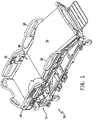
- a patient support apparatussuch as a hospital bed 10, for example, includes a frame 12, a mattress 14, and multiple siderails 16, 18, 20, 22 as shown in Fig. 1 .
- the mattress 14is supported on the frame 12.
- hospital bed 10is a VersaCareTM bed marketed by Hill-Rom Company, Inc.
- the mattress 14includes multiple air bladders 30 which are inflated by an air delivery system 24 (best seen in Fig. 4 ) which is coupled to the frame 12 and in fluid communication with the mattress 14.
- the air delivery system 24includes an air system controller 26 which utilizes information from three pressure sensors 28a, 28b, 28c in fluid communication with the air bladders 30 and which provide a signal to the air system controller 26 indicative of the air pressure in the bladders 30. As will be described in detail below, the pressure in the air bladders 30 is controlled by the air system controller 26 to adjust an interface pressure between the patient and the mattress 14.
- the illustrative embodimentincludes multiple bladders on a patient support such as a hospital bed or hospital bed mattress
- the disclosurecontemplates supports having any of a number of bladders, including at least one bladder.
- the disclosureis equally applicable to person supports used in environments other than a hospital setting, including chairs, sofas, beds and the like. Additional details of the VersaCareTM bed, which is the embodiment illustrated herein, may be found in U.S. Pat. No. 6,691,346 .
- the air system controller 26is programmed with software to monitor pressure in a respective bladder 30 over time and analyze the time based relationship of the air pressure in the bladders 30 to make decisions as to target pressures to be set in various bladders 30 of the mattress 14.
- the softwaredetermines which of the bladders 30 are predominantly supporting the patient and adjusts the target pressures of the bladders 30 to adjust the interface pressures between the mattress 14 and a patient supported on the mattress 14.
- the illustrative mattress 14is divided into four support zones; a head section zone 32, a seat section zone 34, a leg section zone 36, and a foot section zone 38.
- Head section zone 32supports the upper body of a patient residing on the mattress 14.
- the seat section zone 34supports the buttocks and upper thigh portion of a patient on mattress 14.
- Leg section zone 36supports the patient's legs in the mid thigh through the calf area.
- the foot section zone 38supports the heels of a patient lying in a supine position on the mattress 14.
- the head section zone 32, the seat section 34, and the foot section zone 38each have inflatable bladders 30 which serve as support structure for the patient in those areas.
- Leg section zone 36 of the illustrative embodimenthas foam material and does not provide any active pressure management.
- the foam materialis perforated to allow the foam to expand and retract along the longitudinal dimension of the foot section as the foot section is lengthened or shortened by mechanisms included in hospital bed 10. It should be understood that, in other embodiments, the foam material may be omitted and replaced with air bladders to provide support and pressure management for the patient in that area. Mattresses having any number of inflatable support zones, not just four zones, are contemplated by this disclosure.
- head section zone 32includes nine air bladders 30 oriented transversely to a longitudinal length of the hospital bed 10 with all of the bladders 30 plumbed together to form a single closed volume in head section zone 32.
- seat section zone 34comprises six transverse bladders 30 plumbed together so that the bladders 30 form a single closed volume.
- foot section zone 38comprises four bladders 30. Multiple bladders 30 are used in each zone in order to distribute support of the patient over multiple structures.
- Each of the bladders 30are subject to the same target pressure. The target pressure is substantially equal across all bladder in each zone but the use of multiple bladders 30 provides multiple structures to support a patient's body in a particular zone.
- the zones 32, 34, and 38each have a conduit, illustratively embodied as a hose, which communicates between the zone and a manifold 40 of the air delivery system 24 with each hose for each zone being connected to each bladder in the zone.
- Hose 44is in communication with head section zone 32
- hose 46is in communication with seat section zone 34
- hose 48is in communication with foot section zone 38.
- each zone 32, 34, and 38has an independent sense line which senses and communicates the pressure in the zone between the respective zone and a pressure sensor 28 dedicated to the zone.
- Sense line 50is in communication with head section zone 32
- sense line 52is in communication with seat section zone 34
- sense line 54is in communication with foot section zone 38.
- the sense linesare connected to ends of the bladders 30 opposite the ends to which the hoses 44, 46, and 48 are connected, but this need not be the case.
- distal sensingor, in other words, sensing a pressure at a point distal to the hose delivering pressurized air results in improved performance of a pressure based feedback control system such as the system employed in the illustrative embodiment, but again, this arrangement is optional.
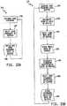
- the air system controller 26, the manifold 40, and a compressor 64are all included in the air delivery system 24 as shown diagrammatically in Fig. 4 .
- the air system controller 26is electrically coupled to the compressor 64 and the manifold 40.
- the manifold 40includes six valves 66a, 66b, 66c, 66d, 66e, and 66f, with valves 66a, 66b, and 66c operating as fill valves and valves 66d, 66e, and 66f operating as vent valves.
- the fill valves 66a, 66b, and 66ccontrol the flow of air from a conduit, illustratively embodied as hose 68, to each of the respective support zones 32, 34, and 38.
- the vent valves 66d, 66e, and 66feach control the venting of the respective support zones 32, 34, 38 to atmosphere.
- Each of the sense lines 50, 52, 54communicates with respective pressure sensors 28a, 28b, and 28c.
- the pressure sensors 28a, 28b, and 28care part number MPXV5010GC7U pressure transducers available from Motorola, Schaumburg, Illinois.
- the air system controller 26utilizes a part number AT89C51 CC03 microprocessor from Atmel Corporation, San Jose, California and which includes processor 42, random access memory 56, volatile memory 58, and a network interface 60.
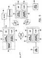
- the air system controller 26is part of a controller area network (CAN) 62 as illustrated in Fig. 5 .
- Hospital bed 10has multiple CAN nodes which provide distributed control of the various functions and features of the hospital bed 10.
- the transducers 28a, 28b, and 28care pneumatically coupled to zones 32, 34 and 38 and electrically coupled to the processor 42.
- the air system controller 26operates locally to set target pressures in each of the support zones 32, 34, and 38 and to control the air delivery system 24 to maintain the pressure in each of the support zones 32, 34, and 38 utilizing the target pressures as set points and controlling the opening and closing of the valves 66a-66f and the operation of compressor 64 to achieve the target pressures within a tolerance range.
- the air system controller 26relies on the pressures sensed by pressure sensors 28a-28c along with elapsed time to perform the pressure control analysis. Additionally, the air system controller 26 relies on information provided by other nodes on the CAN 62. As can be seen in Fig. 5 , the hospital bed 10 includes a scale system controller 70 and a logic module 72.
- the scale system controller 70 and logic module 72are configured similarly to the air system controller 26 and each include a processor 42, RAM 56, volatile memory 58, and a network interface 60.
- the air system controller 70, scale system controller 70, and logic module 72communicate via the CAN 62 and are thereby electrically connected.
- the scale system controller 70receives information from weight sensors, such as , illustratively, four load beams 74a, 74b, 74c, and 74d which is converted by the scale system controller 70 to a patient weight utilizing methods known in the art.
- the weight of the patientis supported on the load beams 74a, 74b, 74c, and 74d such that the signal from the load beams 74a, 74b, 74c, and 74d is indicative of the weight.
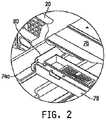
- the location of the load beam 74a within frame 12is shown in Fig. 2 .
- Frame 12includes a support deck 76 which supports mattress 14.
- Support deck 76comprises multiple members or sections that articulate relative to an upper frame 78.
- Upper frame 78is supported relative to intermediate frame 80 on four load beams 74a, 74b, 74c, and 74d.
- the remaining load beams 74b, 74c, 74dare all mounted between upper frame 78 and intermediate frame 80 in a manner similar to load beam 74a.
- the location of the load beams 74b, 74c, 74d relative to the support deck 76is shown diagrammatically in Fig. 6 .
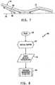
- the logic module 72receives a signal from an angle sensor 82 to determine the relative angle of inclination of a head section 84 (best seen in Fig. 1 ) of mattress 14.
- a head section 84is inclined by the articulation of a head portion 86 of support deck 76 relative to the upper frame 78.
- the articulationis driven by a linear actuator 88 in the illustrative embodiment.
- the linear actuator 88includes a potentiometer (not shown) which is driven by a motor (not shown) of the linear actuator 88. Rotation of a drive wheel of the potentiometer changes the resistance value of the potentiometer and thereby provides an indication of the length of linear actuator 88.
- the length of linear actuator 88is correlated by the controller 26 to an angle of articulation of head portion 86 relative to upper frame 78 and the resulting angle of articulation of head section 84 of mattress 14.
- other devicesmay be used to provide a signal indicative of the articulation of a section of the patient support.
- an accelerometer, a ball switch, limit switches, or other devicesmay be used to indicate articulation of a section.
- the angle of articulation and patient weight dataare available on the CAN 62 as network messages and are therefore available to the air system controller 26.
- the air system controller 26utilizes the angle of articulation, the patient weight, and the pressure sensed in the support zones 32, 34, and 36 to analyze the operations of the air delivery system 24 and to determine what control activities, if any, are indicated.
- the air system controller 26includes software resident in RAM 56 to perform the algorithms necessary to control air delivery system 24.
- the parameters controlledare activation of the various valves 66a-66f and the operation of compressor 64.
- Illustrative valves 66a-66fare solenoid valves which are normally closed and which are energized to allow flow through the valve.
- the solenoid valvesare part number SY-124-6HZ-X70 valves available from SMC Corporation of America, Indianapolis, Indiana.
- air compressor 64is a part number 6025 SE air compressor available from Thomas, Inc., Sheboygan, Wisconsin.
- the air system controller 26acquires data from the various inputs (i.e., angle sensor 82, pressure sensors 28a-28c, and load beams 74a-74d) through the network at regular intervals, processes the information from these inputs, and signals the outputs (i.e., valves 66a-66f and compressor 64) appropriately.
- the air system controller 26 softwaretransitions between states as necessary to control the air delivery system 24, with each state representing a different control routine.
- the CAN 62has a central scheduler which schedules the activities of various control routines within the hospital bed 10 operating system.
- the schedulerassures the integrity of global variables utilized by the various nodes of the CAN 62 and allocates network resources to the various nodes. Focusing on the control routines of the air system controller 26, a diagram of an initialization routine 88 of the air system controller 26 is shown in Fig. 8 .
- the initialization routine 88is called by a main control routine 90.
- an initialization step 92is performed where global variable values are set in the air system controller 26.
- Initialization step 92is followed by preparation of the air system controller 26 state machine at step 94 where the parameters of the system start-up, such as conditions of reset, are considered and a mode of operation is selected consistent with those parameters.
- the pressure management operation control 96 routineis entered.
- the air system controller 26commences the pressure management operation control routine 96 as indicated at block 126 shown in Fig. 9 .
- the air system controller 26considers patient weight, an articulation position of the patient support, a skin damage flag, and a patient sitting up flag to determine a target pressure for each of the zones 32, 34, and 38.
- the equations for calculation of target pressuresare in the form of:
- the air system controller 26gets the load beam data indicative of patient weight from the scale system controller 70 at step 128 and the head elevation data from the logic module 72 at step 130. The air system controller then determines, at step 132, in which head angle region the head section is positioned.
- the head angle region evaluationis a tabular look up which determines a particular factor to use in the calculation of target pressures based on the position of the head angle and the most recent direction of travel of the head portion 86 of support deck 76.
- An illustrative example of the use of head angle intervalsis that when the head section is raised, a first factor is applied from 0-10 degrees of elevation, a second factor is applied from 10-20 degrees of elevation, a third factor is applied from 20-30 degrees of elevation, a fourth factor is applied from 30-40 degrees of elevation, a fifth factor is applied from 40-50 degrees of elevation, a sixth factor is applied from 50-60 degrees of elevation, and a seventh factor is applied from 60-65 degrees of elevation.
- the seventh factoris applied from 65-56 degrees of elevation
- the sixth factoris applied from 55-46 degrees of elevation
- the fifth factoris applied from 45-36 degrees of elevation degrees of elevation
- the fourth factoris applied from 35-26 degrees of elevation
- the third factoris applied from 25-16 degrees of elevation
- the second factoris applied from 15-6 degrees of elevation
- the first factoris applied from 5-0 degrees of elevation.
- the systemconsiders direction of travel in order to compensate for angle sensing hysteresis in the head angle measurement.
- the combination of the head portion articulation linkage 86 and the head portion drive 88have settling characteristics which permit the system to settle after the drive has stopped operation. The settling is affected by momentum such that a lowering head portion 86 will settle differently than a lifting head portion 86 which alters the hysteresis experienced.
- the air system controller 26utilizes the patient weight information and head angle to calculate a target pressure for one of the support zones 32, 34, or 38.
- the description hereinafterwill discuss the monitoring, analysis and control of a singular zone. It should be understood that the process is applicable to any of a number of support zones supporting a patient.
- the target pressure calculatedrepresents a desired pressure which is believed to avoid injury to the patient's skin if the patient remains in a fixed position on the mattress 14 for an extended time.
- an acceptable tolerance for the target pressureis established as discussed in detail below.
- the air system controller 26adjust to a pressure that is within this acceptable tolerance. Specifically, at step 136 the air system controller 26 gets the current pressures in the zone read by the appropriate pressure sensor 28a, 28b, and 28c for the zone. At step 138, the actual pressure in the zone is compared to the target pressure calculated in step 134. If the actual pressure is within an acceptable tolerance of the target pressure, the control routine 96 advances to step 140. However, if the actual pressure is out of an acceptable tolerance band, the air system controller 26 adjusts the pressure in the zone at step 142.
- This adjustmentutilizes a proportional-integral-derivative (PID) control routine to control the operation of the compressor 64 and zone fill valve 66a, 66b, or 66c and vent valve 66d, 66e, 66f to adjust the pressure in the zone to be within an acceptable tolerance of the target pressure for the zone.
- PIDproportional-integral-derivative
- the systemdetermines a related bogey pressure.
- the bogey pressureis developed as an "over-shoot" value. If the system is inflating a zone, the bogey pressure is set slightly greater than the target pressure. In the illustrative embodiment, the bogey pressure is set at 124 Pa (0.93 mm of mercury, 0.5 inches of water) greater than the target pressure.
- the pressure in the zoneis monitored until the bogey pressure is reached. At that point, inflation is halted. Once the zone has had time to settle, the system checks the actual pressure and compares the actual to the target to confirm that the actual pressure is within an acceptable tolerance of the target.
- the bogey pressureis set slightly lower than the target pressure when the system is in the deflate mode. In the illustrative embodiment, the bogey pressure is set at 124 Pa (0.93 mm of mercury 0.5 inches of water) less than the target pressure. The use of the bogey pressure allows for hysteresis in the system as the pressure is changing. Empirical evidence has shown that the offset between the bogey and the target results in an actual pressure within an acceptable tolerance of the target.
- the tolerance band sizein chosen to provide effective pressure management while reducing the potential for dithering of the PID control routine. For example, a tolerance of about +/- 187 Pa (1.4 mm of mercury, 0.75 inches of water) provides a reasonable tolerance from the target.
- Step 140diagrammatically represents a subroutine which collects pressure data from the zone to be utilized by the pressure management control routine 96 in responding to changes in the inputs to the air system controller 26.
- the subroutine 140is presented in Fig. 10A .
- Subroutine 140operates continuously with the processor 42 scheduler multi-tasking to call subroutine 140 at regular intervals.
- the collect pressure data subroutine 140captures the current zone pressure
- the zone pressure data bufferis shifted in a first in first out (FIFO) fashion create a memory location for the latest pressure data point.
- the new zone pressure data pointis written to the buffer.
- Subroutine 140maintains the pressure data for use by other subroutines of the pressure management control routine 96.
- the size of the pressure data buffermay be selected so as to provide a sufficient sample size to perform statistics over the particular sample period. This period may be as small as a few milliseconds or as large as several minutes. In one exemplary embodiment, a polling rate of once every 20 ms and a buffer size of thirty data points is used.
- the pressure management control routine 96calls another subroutine at step 174.
- Subroutine 174shown in Fig. 10B , is a pressure analysis subroutine which calculates statistics on data in the pressure data buffer.
- the pressure analysis subroutine 174also operates continuously with the processor 42 scheduler multi-tasking to call subroutine 174 at regular intervals to perform the calculations.
- the pressure analysis subroutine 174acquires the data from the pressure data buffer.
- subroutine 174calculates the sample mean of the data points in the data buffer.
- the mean data stored in a mean data bufferis shifted to make room for the new sample mean.
- the new mean sample data pointis stored in the buffer.
- the analyze pressure subroutine 174calculates the standard deviation of the data in the buffer.
- the buffer storing sample standard deviation datais shifted in a FIFO fashion to make room for the new sample standard deviation data.
- the data pointis stored in the data buffer.
- the statistical calculationsare made once every 600 ms. This calculation rate, along with the data capture rate of the collect pressure data subroutine 140 described above, provides sample statistics on zone pressure data of a sample size of six data points. Additionally, the sample statistics buffer sizes for both the mean and sample standard deviation is six data points each. Therefore, data is available for the zone pressures for the previous 3.6 seconds, at any given time.
- control routine 96 shown in Fig. 9shows the check pressure data subroutine 140 and analyze pressure subroutine 174 being conducted in a sequential fashion, it should be understood that the scheduler of processor 42 may multi-task the processor to operate the subroutines continuously. Therefore, at any given time, the data from the subroutines is available to be used by other processes and subroutines of pressure management control routine 96.
- Pressure management control routine 96evaluates the historical information of the pressure in the zone at step 144.
- Step 144is a decision step which evaluates whether a pressure shift has been indicated in the zone based on the statistics developed in the analyze pressure subroutine 174.
- the decision as to whether or not a pressure shift is indicatedis based on the change in the mean pressure in the zone on an absolute pressure basis.
- the pressure shift analysismay utilize any of a number of other statistical techniques such as a t-test, F-test, or the like. If a pressure shift is indicated at step 144, pressure management control routine 96 advances to step 146 which is a subroutine for performing a load beam check and is shown in Fig. 12 .
- the load beam check subroutine 146captures the patient absent weight at step 148.
- the patient absent weightis the tare weight measured at each beam independently when a patient is known to be absent from the hospital bed 10.
- load beam check subroutine 146captures the historical load beam zeros which are the correction values or beam constants which represent the offset in the beams due to electrical and mechanical variation. This information allows the load beam data to be compensated for the built-in error that exists in the beam.
- load beam check subroutine 146captures the stored patient weight data from the scale system controller 70. This data is provided on a beam by beam basis and the system to sums the values sensed by each of the load beams in the scale system to arrive at an actual total patient weight.
- the actual patient weightis captured by the perform load beam check subroutine 146. Again, the weight captured is on a beam by beam basis.
- the current patient weight captured at step 154is compared to the historic patient weight captured at step 152 with adjustments made based on the patient absent weight gathered at step 148 and the historic load beam zeros gathered at step 150.
- Patient weight information developed at step 190is stored in an information buffer at step 192.
- Information buffermaintains a comparison of the change in position of the patient on the mattress 14 as predicted by the load beam data. This is determined on a change basis. It should be noted that a patient's actual position (i.e., the location of the patient's center of gravity) is never calculated.
- the information in the information bufferis processed at step 194 to develop data which may support or contradict the possibility that a patient has changed position along the longitudinal length of the hospital bed 10.
- subroutine 146called by the scheduler of the processor 42 which continuously multi-tasks the processor 42.
- the data developed by a subroutine 146is available for analysis by the pressure management operation control routine 96.
- a pressure change rate testmay be triggered at decision step 196.
- Decision step 196evaluates the information from both the analyze pressure subroutine 174 and the load beam check subroutine 146 weighing the data available to determine that a pressure change rate trigger is justified.
- a change rate triggermay be justified if the combination of the pressure shift and the load beam information statistically supports an inference that the patient resident on the mattress has sat up. This decision is based on the magnitude of the pressure shift and the magnitude of the change in the weight distribution of the patient on the load beams longitudinally on hospital bed 10.
- K 1is a predefined value based on the patient weight and the last known patient position.
- K 2is also a predefined value based on the patient weight.
- the valuesare stored in lookup tables which are accessed by the air system controller 26.
- the weighting of the pressure shift as compared to the weight shiftvaries depending on the patient weight. For example, K 2 may be larger for a 45 kg (100 pound) patient then for a 113 kg (250 pound) patient. Similarly, K 1 may be smaller for a 45 kg (100 pound) patient as compared to a 113 kg (250 pound) patient.
- the Likelihood valueis driven mostly by K 1 and the pressure shift.
- the load beam check and weight shiftmay be omitted and the decision to trigger a pressure change rate test may be entirely dependent on the magnitude of the pressure shift. See pages 144-150 of Appendix 2 and pages 18-45 of Appendix C of U.S. Provisional Patent Application 60/702,645 , for a specific example of the K1 and K2 values and the approach described herein as executed in the VersaCareTM product.
- a pressure change rate test subroutine 198is called.
- the subroutine 198is a test that is performed to evaluate whether or not the patient is present on the particular zone being evaluated based on a pressure signal.
- Subroutine 198shown in Fig. 11 , begins at step 200 by initiating a timer.
- Subroutine 198advances to step 202 where an inflation rate zone test is initiated. The purpose of this test is to evaluate the rate of pressure change which occurs in the zone to evaluate the presence of a portion of the patient on that zone. Referring to Fig. 13 , a diagram of the pressure in an expandable volume is represented by the line 204.
- the region 206is generally linear as the expandable volume is filled as a greater and greater pressure is required to expand the volume. Once the expandable volume has reached an elastic limit, the pressure increases much more rapidly over time because additional air no longer expands the bladder volume, once the bladder is fully inflated.
- the derivative of the curve 204, dP/dtis the instantaneous slope of the curve at any point in time. A transition of the curve from the portion 206 to the portion 208 results in a change in the slope of the curve dP/dt. By comparing the slope of the curve to a predetermined criteria, the transition of the expandable volume from a relatively elastic expansion to a relatively inelastic expansion can be detected.
- a bladder which supports an individualreaches the elastic limit more quickly than an unloaded bladder, so the air system controller 26 is able to discern that a load is applied to the bladder.
- a bladder under loaddeflates more rapidly as compared to an unloaded bladder as the weight of the individual tends to force air from the bladder.
- step 210the timer status is evaluated. If the timer has reached its limit, then subroutine 198 advances to step 214. If the timer has not reached its limit, the subroutine loops through step 212 which is a continue process and returns to decision step 210. This assures that pressure data is captured in specific, predetermined time intervals to assure the integrity of the calculations made within subroutine 198. In the illustrative embodiment, samples are taken at 20 millisecond intervals. At step 214, the subroutine captures the pressure data for the first time interval. The subroutine then advances to decision step 216 where an analysis of the data array size is made.
- the bufferincludes thirty samples to provide a sufficient time window of data for analysis. If the sample is not complete then subroutine 198 advances to step 218 wherein instantaneous dP/dt is calculated by comparing the most recent data point to the previous data point to determine the change in pressure over the 20 ms interval. Subroutine 198 then advances to step 220 wherein the instantaneous dP/dt is written to memory. At step 222 the latest two dP/dt values are compared in a filter to assure that there has not been an unexpected shift in dP/dt. An unexpected shift in dP/dt may be caused by patient movement during the performance of the pressure change rate test.
- the subroutine 198performs an error check to determine if an error indicative of a failure of the data integrity corrupting the pressure rate change test has occurred. If there has been a corruption, the subroutine 198 advances to step 202 and initiates the zone inflation test again which results in clearing of any data in the array and starting the tests from the beginning. If there has been no corruption detected by the filter the subroutine advances to step 226 wherein the timer is reset and the subroutine reenters the data collection stream at step 210.
- step 216If the subroutine determines that the data array is complete at step 216 then the subroutine advances to step 228 to determine the dP/dt statistics. Once the statistics are calculated the subroutine 198 returns to the pressure management control routine 96 at step 230. Pressure management control routine 96 then advances to step 232 as shown in Fig. 9 , and utilizes the statistics developed by the perform pressure change rate test subroutine 198 to evaluate whether or not the patient is sitting up at decision step 232. In the illustrative embodiment, the first fifteen data points are averaged and the second fifteen data points are averaged. The difference of the two averages is taken and the difference is multiplied by two. This information is then analyzed to determine the position of the patient.
- a dP/dt greater than a threshold valuemay be indicative that a patient is supported on the bladder. For example, if it is determined that the patient is not on the head zone 32, but the system otherwise concludes the patient is on the bed 10, (e.g., via the weight sensor readings) then this is indicative that the patient is sitting up.
- the air system controllercan assess the position of the patient on the mattress 14.
- the pressure change rate testis utilized in the head section zone 32 and seat section zone 34. It should be understood that the pressure change rate test could be performed in the head section zone 32 only, seat section 34 only, foot section zone 38 only, or performed in any two or all three of the zones 32, 34 and 38 simultaneously to improve the accuracy of the patient position determination, if desired.
- the pressure rate change testmay evaluate the dP/dt during inflation or during deflation in any one or all of the zones 32, 34, or 38.
- the statistics used in determining the patient positionmay include an average dP/dt, a linear regression of the dP/dt, a t-test, an F-test, an analysis of variance (ANOVA), or other statistical analysis.
- the systemmust first determine a dP/dt to determine if the change in dP/dt indicates a load is present or an elastic limit has been reached.
- control routine 96advances to step 234 and sets a patient sitting up flag. If the determination results in a finding that the patient is not sitting up, then be control routine 96 advances to step 236 and clears the patient sitting up flag. In either case, the control routine 96 returns to step 132. As discussed above, the patient sitting up condition is considered when determining the target pressure at step 134 of routine 96.
- historical changes in the pressure or pressure statisticsmay be used to determine that a patient has changed positions on one or more zones 32, 34, and 38. For example, while a patient may be continued to be supported on a zone 32, 34, or 38, a change in pressure may be indicative that a patient has rolled from a supine position to a side-lying position (i.e., the patient positioned on the patient support with the majority of their weight supported on their side as opposed to on their posterior in a supine position or anterior in a prone position).
- step 238which is a perform damage assessment subroutine.
- Subroutine 238is also a subroutine which the multi-task scheduler of the processor 42 calls regularly. Damage assessment subroutine 238 is shown diagrammatically in Fig. 15 .
- the first step of the damage assessment subroutine 238is step 240 where the subroutine 238 acquires the target pressure P target for the zone. Because the damage assessment is an accumulation of pressure deviation from the P target , the subroutine must capture a time value which is performed at step 242.
- the subroutine 238then advances to step 244 where the pressure in the zone, P actual is acquired from the appropriate pressure sensor 28a, 28b, or 28c.
- subroutine 238determines a damage factor which is determined by the value of
- a damage factorwhich is determined by the value of
- FIG. 14an illustration of the variation of P actual as compared to P target over time illustrates the concept of a damage factor.
- P actualmay deviate from P target due to slight changes in position of the patient or leaks in the air delivery system 24 which allows air to escape from the particular zone.
- Damage assessment subroutine 238acquires data which is an approximation of the area between the P actual curve and the P target line. The area between the P actual curve and the P target line represents theoretical damage to the patient's skin due to the variation from the target pressure.
- the latest damage factoris added to the previously accumulated zone damage to update the total damage accumulation.
- the new total damage accumulationis stored in memory and an evaluation of the theoretical damage in the applicable zone is performed at step 252 to determine if the damage is excessive (e.g., greater than a threshold).
- a threshold value of damage for each particular zoneis predefined based on a given patient weight.
- the damage thresholdmay be variable for a given patient weight based on the deviation of P actual from P target on an absolute basis. For example, referring to Fig. 14 , lines 255a and 255b represent a 30% variation from P target 402 and line 254a and 254b represent a 45% variation from P target 402.
- the accumulation factoris multiplied by a weighting factor which results in a heavier weighting of the variation outside of the tolerance bands 255a and 255b.
- the accumulation factoris be multiplied by a weighting factor greater than the weighting factor for the tolerance bands 255a or 255b.
- the excessive damage flag for the zoneis set at step 254.
- the excessive damage flag statusis evaluated by the pressure management control routine 96 at decision step 256. If the excess damage flag is set, then pressure management control routine 96 returns to step 134 where the support zone target pressure is recalculated and the control routine 96 adjusts to the new target pressure and continues to monitor the operation of the air system controller 26. As discussed above, the target pressure calculated is dependent upon whether the damage flag has is set.
- control routine 96continues to a head angle monitor subroutine 258.
- Subroutine 258, shown in Fig. 16captures the previous head angle reading from memory at step 260.
- subroutinecaptures the current head angle reading.
- the previous head angle reading and the current head angle readingare compared to determine if a change in head angle has been made. This determination may involve a tolerance band of change in the head angle to account for instability in the head angle reading from patient movement or other oscillations or system movement.
- the head angle change determinationmay be supplemented by monitoring current to the head portion drive motor.
- the head angle change determinationmay be supplemented by monitoring of inputs used to control the head angle to evaluate if a request to change head angle has been made.
- subroutine 258advances to step 266 where the head angle change flag is cleared. The subroutine then loops back to step 260 to repeat the evaluation. If the head angle is determined to be different at step 264, the subroutine advances to step 268 where the head angle change flag is set. The subroutine 258 then advances to step 270 where a delay is built into the system to allow sufficient time for the change angle flag to be read by the control routine 96. In the illustrative embodiment, subroutine 258 is called once every 200 ms and the delay at step 270 is set at 200 ms so that if the flag is set, it will be read in at least one subsequent call. Once the delay is met, the subroutine 258 returns to step 260 to repeat the evaluation.
- the pressure management operation control routine 96advances from subroutine 258 to step 272 where the control routine 96 evaluates the status of the angle change flag. If the flag is set, control routine 96 returns to step 130 to recalculate the target pressure and continue through control routine 96. If the angle change flag is not set, control routine 96 returns to step 136 where the status of pressure in the zone is reevaluated and pressure management control routine 96 continues to control operation of the air system controller 26.
Landscapes
- Health & Medical Sciences (AREA)
- Life Sciences & Earth Sciences (AREA)
- Veterinary Medicine (AREA)
- Animal Behavior & Ethology (AREA)
- General Health & Medical Sciences (AREA)
- Public Health (AREA)
- Engineering & Computer Science (AREA)
- Medical Informatics (AREA)
- Biophysics (AREA)
- Pathology (AREA)
- Nursing (AREA)
- Biomedical Technology (AREA)
- Heart & Thoracic Surgery (AREA)
- Physics & Mathematics (AREA)
- Molecular Biology (AREA)
- Surgery (AREA)
- Physiology (AREA)
- Dentistry (AREA)
- Oral & Maxillofacial Surgery (AREA)
- Invalid Beds And Related Equipment (AREA)
- Mattresses And Other Support Structures For Chairs And Beds (AREA)
Description
- The present disclosure relates to a control system for the control of pressure in a patient support. More particularly, the present disclosure relates to a control system for an inflatable support surface that utilizes pressure data to determine a patient's position on the patient support.
- Patient supports, such as hospital beds, and some beds used at home have inflatable support surfaces such as mattresses, for example, on which a person is supported. Such mattresses have one or more air bladders which are inflated and deflated to control the pressure in the bladders. The pressure in the bladders correlates to the interface pressure between the skin of the person supported on the surface and the support surface. Prolonged exposure to excessive pressure and/or skin shear tends to break down the skin and form pressure ulcers, also known as bed sores.
EP-A2-0853918 describes a device for monitoring the body movements of a patient on a support, the device comprising at least one fluid filled cell inserted between the patient and the support and a detector of fluctuations in the state of the fluid in the cell caused by body movement of the patient, providing an output dependent on the fluctuations.- The present disclosure comprises the features recited in the appended claims.
- According to this disclosure, a patient support comprises a source of pressurized air, a valve, a bladder, a pressure sensor and a controller. The valve is in fluid communication with the source of pressurized air and with the bladder. The bladder is in fluid communication with the pressure sensor. The controller is in electrical communication with the source of pressurized air, the valve, and the first pressure sensor. The controller comprises a processor, and a memory device electrically coupled to the processor. The memory device stores a plurality of instructions which, when executed by the processor, cause the processor to operate the source of pressurized air and the valve to inflate the bladder, monitor the first pressure signal during the inflation to determine a rate of change of pressure in the bladder, and determine whether the patient is supported on the bladder based on the rate of change. The bladder may be inflated or deflated and the rate of change of pressure may be determined during inflation or deflation as the case may be. The patient support may have multiple bladders and the rate of change of pressure may be determined for one or more of the multiple bladders.
- The processor may operate the valve to deflate the first bladder, monitor the first pressure signal during the deflation to determine a rate of change of pressure in the first bladder, and determine whether the patient is supported on the first bladder.
- The processor may establish a target pressure for the first bladder, inflate the first bladder to a pressure within an acceptable tolerance of the target pressure, monitor the first pressure signal, compare the first pressure signal to the target pressure to determine a deviation of the first pressure signal from the target pressure, accumulate the magnitude of pressure deviation over time, and output a signal if the accumulated magnitude exceeds a maximum value. The system may inflate or deflate the bladder back to within the tolerance range in response to the signal. The processor, therefore, may allow a period of time to elapse when the pressure is outside of the tolerance range before pressure adjustments are made. The period of elapsed time may vary depending on how far outside of the tolerance the measured pressure deviates.
- The patient support may comprise the source of pressurized air; the first bladder and a second bladder; the first valve and second, third and fourth valves; the first pressure sensor and a second pressure sensor; and the controller. The first valve may be in fluid communication with the source of pressurized air and with the first bladder and configured to control the flow of air between the source of pressurized air and the first bladder. The second valve may be in fluid communication with the first bladder and configured to control the flow of air out of the first bladder. The third valve may be in fluid communication with the source of pressurized air and with the second bladder and configured to control the flow of air between the source of pressurized air and the second bladder. The fourth valve may be in fluid communication with the second bladder and configured to control the flow of air out of the second bladder. The first pressure sensor may be in fluid communication with the first bladder and produce a first pressure signal indicative of air pressure within the first bladder. The second pressure sensor may be in fluid communication with the second bladder and produce a second pressure signal indicative of air pressure within the second bladder. The controller may be in electrical communication with the source of pressurized air, valves, and pressure sensors. The processor may establish a position of the patient supported on the first bladder by comparing the rate of change of pressure in the first bladder to the rate of change of pressure in the second bladder, monitor the first and second pressure signals, and determine whether the patient has changed positions on the first and second bladders.
- The processor may cause the processor to establish a target pressure for the first bladder, determine the acceptable tolerance for the target pressure by evaluating the stability of the first pressure signal over time, and control pressure in the first bladder to within an acceptable tolerance of the target pressure by operating the source of pressurized air and the first valve to inflate the first bladder and operate the second valve to deflate the first bladder and monitor the first pressure signal during the operation of the source of pressurized air and first and second valves.
- The control system may be operable to control a pressure at which the at least one bladder is inflated, the pressure being determined automatically as a function of a weight of the patient, a position of the patient on the patient support, and an amount that a least a portion of the patient support is articulated, wherein the position of the person is automatically determined by the control system by monitoring a rate of change of pressure in the at least one inflatable bladder.
- The controller may determine that the patient has changed positions by moving between a supine position and a side-lying position. The controller may determine that the patient has changed positions by moving between a sitting up position and a supine position. The controller may determine that the patient has changed positions by moving between a prone position and a side-lying position. The controller may determine that the patient has changed positions by moving between a sitting up position and a supine position.
- A method of controlling pressure in an inflatable zone of a patient support surface supported on a patient support apparatus may comprise multiple steps. One step may comprise inflating the inflatable zone to a first target pressure. Another step may comprise further inflating the inflatable zone. Yet another step may comprise determining a rate of change of pressure in the inflatable zone resulting from the further inflation of the inflatable zone. Still another step may comprise comparing the rate of change of pressure in the inflatable zone to a threshold value. Yet still another step may comprise adjusting the inflation of the inflatable zone to a second target pressure if the comparison of the pressure rate of change to the threshold value meets predetermined criteria. The predetermined criteria may be a function of the weight of a patient supported on the patient support apparatus or an angle of articulation of a section of the patient support apparatus.
- Yet another method of controlling pressure in a first inflatable zone of a patient support surface may comprise multiple steps as well. One step may comprise inflating the first inflatable zone to a first target pressure and inflating a second inflatable zone of the support surface to a second target pressure. Another step may comprise further inflating the second inflatable zone. Yet another step may comprise determining a rate of change of pressure in the second inflatable zone resulting from the further inflation of the second inflatable zone. Still another step may comprise comparing the rate of change of pressure in the second inflatable zone to a threshold value. Yet still another step may comprise adjusting the inflation of the first inflatable zone to a third target pressure if the comparison of the pressure rate of change to the threshold value meets a predetermined criteria. The predetermined criteria may be a function of the weight of a patient supported on the patient support apparatus or an angle of articulation of a section of the patient support apparatus.
- The processor of the controller determines the rate of change of pressure in a bladder by comparing the change from a first pressure to a second pressure over a known time interval. The processor compares a rate of change to a threshold value to determine if a patient is supported on the bladder. In some embodiments, the determination that a patient is supported on the supported on the bladder may be based on the rate of change being lower than the threshold. In other embodiments, the determination that a patient is supported on the supported on the bladder may be based on the rate of change being higher than the threshold.
- The patient support further includes a weight sensor, such as a load beam, in electrical communication with the processor to input a signal indicative of at least a portion of the weight of the patient supported on the patient support. The threshold value or predetermined criteria is a function of the patient weight
- The patient support may include a position sensor, such as a potentiometer, in electrical communication with the processor to input a signal indicative of the articulation position of a section of the patient support. The threshold value or predetermined criteria may be a function of the articulation position.
- The processor may filter the pressure signal. The processor may filter the signal either during inflation of deflation. The processor may filter the pressure data by taking an average of a number of pressure data points.
- In some embodiments, the patient support may further comprise an additional bladder and an additional pressure sensor which communicates with the additional bladder. The controller may be further responsive to the rate of change in the additional bladder and the threshold value or predetermined criteria may be a function of the rate of change in the additional bladder.
- In some embodiments, pressure deviations above the target pressure may have a first weighting and pressure deviations below the target pressure may have a second weighting and the potential damage accumulation may include the weighted pressure deviations. In some embodiments, the second weighting factor may be less than the first weighting factor.
- The predetermined criteria for damage may be a function of the patient weight. The controller may be responsive to an additional pressure signal from an additional bladder to accumulate the potential damage from the first bladder and the additional bladder and to adjust the target pressure in the bladders if the combined potential damage exceeds a second predetermined value. The second predetermined value may be less than the combined sum of the predetermined values for each of the bladders independently.
- The controller may be responsive to the rate of change of pressure within the bladder to determine whether a patient supported on the patient support has transitioned between a lying position and a sitting position. In some embodiments, the bladder which is analyzed to determine whether the patient has sat up may be positioned to support the back of the patient. In other embodiments, the bladder which is analyzed to determine whether the patient has sat up may be positioned to support the buttocks of the patient. In some embodiments, the controller may be responsive to the rate of change of pressure within multiple bladders to determine whether the patient supported on the patient support has transitioned between a lying position and a sitting position.
- The controller may perform statistical analysis on the rate of pressure change data in determining if predetermined criteria have been met.
- Additional features, which alone or in combination with any other feature(s), including those listed above and those listed in the claims, may comprise patentable subject matter and will become apparent to those skilled in the art upon consideration of the following detailed description of illustrative embodiments exemplifying the best mode of carrying out the invention as presently perceived.
- The detailed description particularly refers to the accompanying figures in which:
Fig. 1 is a perspective view of a hospital bed employing an embodiment of the control system of the present disclosure, the hospital bed including an articulable frame, siderails, and a mattress;Fig. 2 is an enlarged view of the hospital bed ofFig. 1 with portions cut away to illustrate the location of load cells in the hospital bed frame;Fig. 3 is a diagrammatic view of an air system associated with a mattress of the hospital bed ofFig. 1 ;Fig. 4 is a diagrammatic view of the relationship between components of an air system controller of the air system ofFig. 3 and the mattress;Fig. 5 is a diagrammatic representation of the relationship of various portions of a controller area network (CAN) of the hospital bed ofFig. 1 ;Fig. 6 is a diagrammatic representation of the location of various load cells to a support deck of the hospital bed ofFig. 1 ;Fig. 7 is a side view of the hospital bed ofFig. 1 with portions cut away, the side view illustrating the relationship of a head portion drive to a head portion of a support deck of the hospital bed ofFig. 1 ;Fig. 8 is a flowchart of the initialization of software associated with control of an air mattress of the hospital bed ofFig. 1 ;Fig. 9 is a flow chart of a software control routine of the air system controller ofFig. 4 ;Fig. 10A is a flow chart of a data management subroutine used to store pressure data associated with the operation of the mattress ofFig. 3 ;Fig. 10B is a flow chart of a data management subroutine used to perform and store statistical information based on the data captured in the subroutine ofFig. 10A ;Fig. 11 is a flow chart of a pressure rate test subroutine used to analyze the pressure rate change within a bladder of the mattress ofFig. 3 during inflation of the mattress;Fig. 12 is a flow chart of a load beam check subroutine used to analyze load beam data associated with the load beams ofFig. 6 ;Fig. 13 is a graphical representation of pressure as a function of time within a bladder of the mattress ofFig. 3 during inflation of the bladder;Fig. 14 is a graphical representation of an example of actual pressure as a function of time as it relates to a target pressure;Fig. 15 is a flowchart of a damage accumulation subroutine used by software of the air system controller ofFig. 4 to analyze the potential for damage to the skin of a patient residing on the mattress ofFig. 3 due to variations from a target pressure in a bladder of the mattress; andFig. 16 is a flow chart of a subroutine which monitors for variations in an angle of articulation of a head portion of the hospital bed ofFig. 1 .- A patient support apparatus such as a
hospital bed 10, for example, includes aframe 12, amattress 14, andmultiple siderails Fig. 1 . Themattress 14 is supported on theframe 12. In the illustrative embodiment,hospital bed 10 is a VersaCare™ bed marketed by Hill-Rom Company, Inc. Referring now toFigs. 3 and4 , themattress 14 includesmultiple air bladders 30 which are inflated by an air delivery system 24 (best seen inFig. 4 ) which is coupled to theframe 12 and in fluid communication with themattress 14. Theair delivery system 24 includes anair system controller 26 which utilizes information from threepressure sensors air bladders 30 and which provide a signal to theair system controller 26 indicative of the air pressure in thebladders 30. As will be described in detail below, the pressure in theair bladders 30 is controlled by theair system controller 26 to adjust an interface pressure between the patient and themattress 14. - While the illustrative embodiment includes multiple bladders on a patient support such as a hospital bed or hospital bed mattress, the disclosure contemplates supports having any of a number of bladders, including at least one bladder. Also, the disclosure is equally applicable to person supports used in environments other than a hospital setting, including chairs, sofas, beds and the like. Additional details of the VersaCare™ bed, which is the embodiment illustrated herein, may be found in
U.S. Pat. No. 6,691,346 . - The
air system controller 26 is programmed with software to monitor pressure in arespective bladder 30 over time and analyze the time based relationship of the air pressure in thebladders 30 to make decisions as to target pressures to be set invarious bladders 30 of themattress 14. By monitoring the time based relationship of the pressures in themattress bladders 30, the software determines which of thebladders 30 are predominantly supporting the patient and adjusts the target pressures of thebladders 30 to adjust the interface pressures between themattress 14 and a patient supported on themattress 14. - As shown in
Fig. 3 , theillustrative mattress 14 is divided into four support zones; ahead section zone 32, aseat section zone 34, aleg section zone 36, and afoot section zone 38.Head section zone 32 supports the upper body of a patient residing on themattress 14. Theseat section zone 34 supports the buttocks and upper thigh portion of a patient onmattress 14.Leg section zone 36 supports the patient's legs in the mid thigh through the calf area. Thefoot section zone 38 supports the heels of a patient lying in a supine position on themattress 14. Thehead section zone 32, theseat section 34, and thefoot section zone 38 each haveinflatable bladders 30 which serve as support structure for the patient in those areas.Leg section zone 36 of the illustrative embodiment has foam material and does not provide any active pressure management. In one embodiment, the foam material is perforated to allow the foam to expand and retract along the longitudinal dimension of the foot section as the foot section is lengthened or shortened by mechanisms included inhospital bed 10. It should be understood that, in other embodiments, the foam material may be omitted and replaced with air bladders to provide support and pressure management for the patient in that area. Mattresses having any number of inflatable support zones, not just four zones, are contemplated by this disclosure. - In the illustrative embodiment,
head section zone 32 includes nineair bladders 30 oriented transversely to a longitudinal length of thehospital bed 10 with all of thebladders 30 plumbed together to form a single closed volume inhead section zone 32. Similarly,seat section zone 34 comprises sixtransverse bladders 30 plumbed together so that thebladders 30 form a single closed volume. Also,foot section zone 38 comprises fourbladders 30.Multiple bladders 30 are used in each zone in order to distribute support of the patient over multiple structures. Each of thebladders 30 are subject to the same target pressure. The target pressure is substantially equal across all bladder in each zone but the use ofmultiple bladders 30 provides multiple structures to support a patient's body in a particular zone. - In the illustrative embodiment, the
zones manifold 40 of theair delivery system 24 with each hose for each zone being connected to each bladder in the zone.Hose 44 is in communication withhead section zone 32,hose 46 is in communication withseat section zone 34, andhose 48 is in communication withfoot section zone 38. In addition, eachzone pressure sensor 28 dedicated to the zone.Sense line 50 is in communication withhead section zone 32, whilesense line 52 is in communication withseat section zone 34, andsense line 54 is in communication withfoot section zone 38. In the illustrative example, the sense lines are connected to ends of thebladders 30 opposite the ends to which thehoses - The
air system controller 26, the manifold 40, and acompressor 64 are all included in theair delivery system 24 as shown diagrammatically inFig. 4 . Theair system controller 26 is electrically coupled to thecompressor 64 and the manifold 40. The manifold 40 includes sixvalves valves valves fill valves hose 68, to each of therespective support zones vent valves respective support zones respective pressure sensors pressure sensors - The
air system controller 26 utilizes a part number AT89C51 CC03 microprocessor from Atmel Corporation, San Jose, California and which includesprocessor 42,random access memory 56,volatile memory 58, and anetwork interface 60. In the illustrative embodiment, theair system controller 26 is part of a controller area network (CAN) 62 as illustrated inFig. 5 .Hospital bed 10 has multiple CAN nodes which provide distributed control of the various functions and features of thehospital bed 10. In the illustrative embodiment, thetransducers zones processor 42. - The
air system controller 26 operates locally to set target pressures in each of thesupport zones air delivery system 24 to maintain the pressure in each of thesupport zones valves 66a-66f and the operation ofcompressor 64 to achieve the target pressures within a tolerance range. Theair system controller 26 relies on the pressures sensed bypressure sensors 28a-28c along with elapsed time to perform the pressure control analysis. Additionally, theair system controller 26 relies on information provided by other nodes on theCAN 62. As can be seen inFig. 5 , thehospital bed 10 includes ascale system controller 70 and alogic module 72. Thescale system controller 70 andlogic module 72 are configured similarly to theair system controller 26 and each include aprocessor 42,RAM 56,volatile memory 58, and anetwork interface 60. Theair system controller 70,scale system controller 70, andlogic module 72 communicate via theCAN 62 and are thereby electrically connected. - The
scale system controller 70 receives information from weight sensors, such as , illustratively, fourload beams 74a, 74b, 74c, and 74d which is converted by thescale system controller 70 to a patient weight utilizing methods known in the art. The weight of the patient is supported on theload beams 74a, 74b, 74c, and 74d such that the signal from theload beams 74a, 74b, 74c, and 74d is indicative of the weight. For example, the location of the load beam 74a withinframe 12 is shown inFig. 2 .Frame 12 includes asupport deck 76 which supportsmattress 14.Support deck 76 comprises multiple members or sections that articulate relative to anupper frame 78.Upper frame 78 is supported relative tointermediate frame 80 on fourload beams 74a, 74b, 74c, and 74d. The remainingload beams 74b, 74c, 74d are all mounted betweenupper frame 78 andintermediate frame 80 in a manner similar to load beam 74a. The location of the load beams 74b, 74c, 74d relative to thesupport deck 76 is shown diagrammatically inFig. 6 . - The
logic module 72 receives a signal from anangle sensor 82 to determine the relative angle of inclination of a head section 84 (best seen inFig. 1 ) ofmattress 14. Referring now toFig. 7 , thehead section 84 is inclined by the articulation of ahead portion 86 ofsupport deck 76 relative to theupper frame 78. The articulation is driven by alinear actuator 88 in the illustrative embodiment. Thelinear actuator 88 includes a potentiometer (not shown) which is driven by a motor (not shown) of thelinear actuator 88. Rotation of a drive wheel of the potentiometer changes the resistance value of the potentiometer and thereby provides an indication of the length oflinear actuator 88. The length oflinear actuator 88 is correlated by thecontroller 26 to an angle of articulation ofhead portion 86 relative toupper frame 78 and the resulting angle of articulation ofhead section 84 ofmattress 14. In some embodiments, other devices may be used to provide a signal indicative of the articulation of a section of the patient support. For example, an accelerometer, a ball switch, limit switches, or other devices may be used to indicate articulation of a section. - The angle of articulation and patient weight data are available on the
CAN 62 as network messages and are therefore available to theair system controller 26. Theair system controller 26 utilizes the angle of articulation, the patient weight, and the pressure sensed in thesupport zones air delivery system 24 and to determine what control activities, if any, are indicated. Theair system controller 26 includes software resident inRAM 56 to perform the algorithms necessary to controlair delivery system 24. The parameters controlled are activation of thevarious valves 66a-66f and the operation ofcompressor 64. Illustrative valves 66a-66f are solenoid valves which are normally closed and which are energized to allow flow through the valve. In the illustrative embodiment, the solenoid valves are part number SY-124-6HZ-X70 valves available from SMC Corporation of America, Indianapolis, Indiana. In the illustrative embodiment,air compressor 64 is a part number 6025 SE air compressor available from Thomas, Inc., Sheboygan, Wisconsin. Theair system controller 26 acquires data from the various inputs (i.e.,angle sensor 82,pressure sensors 28a-28c, and load beams 74a-74d) through the network at regular intervals, processes the information from these inputs, and signals the outputs (i.e.,valves 66a-66f and compressor 64) appropriately. Theair system controller 26 software transitions between states as necessary to control theair delivery system 24, with each state representing a different control routine.- The
CAN 62 has a central scheduler which schedules the activities of various control routines within thehospital bed 10 operating system. The scheduler assures the integrity of global variables utilized by the various nodes of theCAN 62 and allocates network resources to the various nodes. Focusing on the control routines of theair system controller 26, a diagram of aninitialization routine 88 of theair system controller 26 is shown inFig. 8 . Theinitialization routine 88 is called by amain control routine 90. Upon being called, aninitialization step 92 is performed where global variable values are set in theair system controller 26.Initialization step 92 is followed by preparation of theair system controller 26 state machine atstep 94 where the parameters of the system start-up, such as conditions of reset, are considered and a mode of operation is selected consistent with those parameters. Once the variables are initialized and the state machine is prepared, the pressuremanagement operation control 96 routine is entered. - After
step 94, shown inFig. 8 , theair system controller 26 commences the pressure managementoperation control routine 96 as indicated atblock 126 shown inFig. 9 . As will be discussed in further detail below, theair system controller 26 considers patient weight, an articulation position of the patient support, a skin damage flag, and a patient sitting up flag to determine a target pressure for each of thezones - When the Patient is Laying Down


- When the Patient is Sitting Up


- When Damage Flag is Set


- The previous status of these conditions (i.e., patient weight, articulation position, skin damage flag, and patient sitting up flag) are used at start-up before the
air system controller 26 begins pressuremanagement control routine 96. - The
air system controller 26 gets the load beam data indicative of patient weight from thescale system controller 70 atstep 128 and the head elevation data from thelogic module 72 atstep 130. The air system controller then determines, atstep 132, in which head angle region the head section is positioned. The head angle region evaluation is a tabular look up which determines a particular factor to use in the calculation of target pressures based on the position of the head angle and the most recent direction of travel of thehead portion 86 ofsupport deck 76. An illustrative example of the use of head angle intervals is that when the head section is raised, a first factor is applied from 0-10 degrees of elevation, a second factor is applied from 10-20 degrees of elevation, a third factor is applied from 20-30 degrees of elevation, a fourth factor is applied from 30-40 degrees of elevation, a fifth factor is applied from 40-50 degrees of elevation, a sixth factor is applied from 50-60 degrees of elevation, and a seventh factor is applied from 60-65 degrees of elevation. When the most recent direction of travel of the head section is lowering, the seventh factor is applied from 65-56 degrees of elevation, the sixth factor is applied from 55-46 degrees of elevation, the fifth factor is applied from 45-36 degrees of elevation degrees of elevation, the fourth factor is applied from 35-26 degrees of elevation, the third factor is applied from 25-16 degrees of elevation, the second factor is applied from 15-6 degrees of elevation, and the first factor is applied from 5-0 degrees of elevation. - The system considers direction of travel in order to compensate for angle sensing hysteresis in the head angle measurement. The combination of the head
portion articulation linkage 86 and thehead portion drive 88 have settling characteristics which permit the system to settle after the drive has stopped operation. The settling is affected by momentum such that a loweringhead portion 86 will settle differently than a liftinghead portion 86 which alters the hysteresis experienced. - At
step 134 theair system controller 26 utilizes the patient weight information and head angle to calculate a target pressure for one of thesupport zones mattress 14 for an extended time. - When the
air system controller 26 is adjusting to a new target pressure, an acceptable tolerance for the target pressure is established as discussed in detail below. Theair system controller 26 adjust to a pressure that is within this acceptable tolerance. Specifically, atstep 136 theair system controller 26 gets the current pressures in the zone read by theappropriate pressure sensor step 138, the actual pressure in the zone is compared to the target pressure calculated instep 134. If the actual pressure is within an acceptable tolerance of the target pressure, the control routine 96 advances to step 140. However, if the actual pressure is out of an acceptable tolerance band, theair system controller 26 adjusts the pressure in the zone atstep 142. - This adjustment utilizes a proportional-integral-derivative (PID) control routine to control the operation of the
compressor 64 and zone fillvalve valve - The tolerance band size in chosen to provide effective pressure management while reducing the potential for dithering of the PID control routine. For example, a tolerance of about +/- 187 Pa (1.4 mm of mercury, 0.75 inches of water) provides a reasonable tolerance from the target. Upon completion of the adjustment loop between
steps - In the software algorithm example of
Fig. 9 , the adjustment of thehead section zone 32,seat section zone 34 andfoot section zone 38 pressures are sequential processes. It should be understood that these processes may occur simultaneously through proper application of theair system controller 26processor 42 scheduling approach. The description of the processes occurring in a sequential fashion is for illustrative purposes only. Those skilled in the art will readily recognize that a control routine may be implemented which minimizes the time to adjust all of the zones by sharing of the pressurized air from thecompressor 64 and appropriate management of thevalves - Step 140 diagrammatically represents a subroutine which collects pressure data from the zone to be utilized by the pressure
management control routine 96 in responding to changes in the inputs to theair system controller 26. Thesubroutine 140 is presented inFig. 10A .Subroutine 140 operates continuously with theprocessor 42 scheduler multi-tasking to callsubroutine 140 at regular intervals. Atstep 156, the collectpressure data subroutine 140 captures the current zone pressure, atstep 158, the zone pressure data buffer is shifted in a first in first out (FIFO) fashion create a memory location for the latest pressure data point. Atstep 160, the new zone pressure data point is written to the buffer.Subroutine 140 maintains the pressure data for use by other subroutines of the pressuremanagement control routine 96. The size of the pressure data buffer may be selected so as to provide a sufficient sample size to perform statistics over the particular sample period. This period may be as small as a few milliseconds or as large as several minutes. In one exemplary embodiment, a polling rate of once every 20 ms and a buffer size of thirty data points is used. - The pressure
management control routine 96 calls another subroutine atstep 174.Subroutine 174, shown inFig. 10B , is a pressure analysis subroutine which calculates statistics on data in the pressure data buffer. Thepressure analysis subroutine 174 also operates continuously with theprocessor 42 scheduler multi-tasking to callsubroutine 174 at regular intervals to perform the calculations. Atstep 176, thepressure analysis subroutine 174 acquires the data from the pressure data buffer. Atstep 178,subroutine 174 calculates the sample mean of the data points in the data buffer. Atstep 180, the mean data stored in a mean data buffer is shifted to make room for the new sample mean. Atstep 182, the new mean sample data point is stored in the buffer. Atstep 184, the analyzepressure subroutine 174 calculates the standard deviation of the data in the buffer. Atstep 186, the buffer storing sample standard deviation data is shifted in a FIFO fashion to make room for the new sample standard deviation data. Atstep 188 the data point is stored in the data buffer. In one exemplary embodiment, the statistical calculations are made once every 600 ms. This calculation rate, along with the data capture rate of the collectpressure data subroutine 140 described above, provides sample statistics on zone pressure data of a sample size of six data points. Additionally, the sample statistics buffer sizes for both the mean and sample standard deviation is six data points each. Therefore, data is available for the zone pressures for the previous 3.6 seconds, at any given time. - While the illustrative embodiment of control routine 96 shown in
Fig. 9 shows the checkpressure data subroutine 140 and analyzepressure subroutine 174 being conducted in a sequential fashion, it should be understood that the scheduler ofprocessor 42 may multi-task the processor to operate the subroutines continuously. Therefore, at any given time, the data from the subroutines is available to be used by other processes and subroutines of pressuremanagement control routine 96. - Pressure
management control routine 96 evaluates the historical information of the pressure in the zone atstep 144. Step 144 is a decision step which evaluates whether a pressure shift has been indicated in the zone based on the statistics developed in the analyzepressure subroutine 174. In one exemplary embodiment, the decision as to whether or not a pressure shift is indicated is based on the change in the mean pressure in the zone on an absolute pressure basis. In other embodiments, the pressure shift analysis may utilize any of a number of other statistical techniques such as a t-test, F-test, or the like. If a pressure shift is indicated atstep 144, pressure management control routine 96 advances to step 146 which is a subroutine for performing a load beam check and is shown inFig. 12 . The loadbeam check subroutine 146 captures the patient absent weight atstep 148. The patient absent weight is the tare weight measured at each beam independently when a patient is known to be absent from thehospital bed 10. Atstep 150, loadbeam check subroutine 146 captures the historical load beam zeros which are the correction values or beam constants which represent the offset in the beams due to electrical and mechanical variation. This information allows the load beam data to be compensated for the built-in error that exists in the beam. Atstep 152 loadbeam check subroutine 146 captures the stored patient weight data from thescale system controller 70. This data is provided on a beam by beam basis and the system to sums the values sensed by each of the load beams in the scale system to arrive at an actual total patient weight. - At
step 154, the actual patient weight is captured by the perform loadbeam check subroutine 146. Again, the weight captured is on a beam by beam basis. Atstep 190, the current patient weight captured atstep 154 is compared to the historic patient weight captured atstep 152 with adjustments made based on the patient absent weight gathered atstep 148 and the historic load beam zeros gathered atstep 150. Patient weight information developed atstep 190 is stored in an information buffer atstep 192. Information buffer maintains a comparison of the change in position of the patient on themattress 14 as predicted by the load beam data. This is determined on a change basis. It should be noted that a patient's actual position (i.e., the location of the patient's center of gravity) is never calculated. The information in the information buffer is processed atstep 194 to develop data which may support or contradict the possibility that a patient has changed position along the longitudinal length of thehospital bed 10. Similarly tosubroutines subroutine 146 called by the scheduler of theprocessor 42 which continuously multi-tasks theprocessor 42. The data developed by asubroutine 146 is available for analysis by the pressure managementoperation control routine 96. - If a potential pressure shift was indicated at
step 144, and the data from loadbeam check subroutine 146 supports the pressure shift decision atstep 144, a pressure change rate test may be triggered atdecision step 196.Decision step 196 evaluates the information from both the analyzepressure subroutine 174 and the loadbeam check subroutine 146 weighing the data available to determine that a pressure change rate trigger is justified. In the illustrative embodiment, a change rate trigger may be justified if the combination of the pressure shift and the load beam information statistically supports an inference that the patient resident on the mattress has sat up. This decision is based on the magnitude of the pressure shift and the magnitude of the change in the weight distribution of the patient on the load beams longitudinally onhospital bed 10. An equation in the form of:
air system controller 26. The weighting of the pressure shift as compared to the weight shift varies depending on the patient weight. For example, K2 may be larger for a 45 kg (100 pound) patient then for a 113 kg (250 pound) patient. Similarly, K1 may be smaller for a 45 kg (100 pound) patient as compared to a 113 kg (250 pound) patient. Typically, the Likelihood value is driven mostly by K1 and the pressure shift. In some embodiments, the load beam check and weight shift may be omitted and the decision to trigger a pressure change rate test may be entirely dependent on the magnitude of the pressure shift. See pages 144-150 of Appendix 2 and pages 18-45 of Appendix C ofU.S. , for a specific example of the K1 and K2 values and the approach described herein as executed in the VersaCare™ product.Provisional Patent Application 60/702,645 - If the Likelihood calculated in Equation 1 exceeds a threshold value, a pressure change
rate test subroutine 198 is called. Thesubroutine 198 is a test that is performed to evaluate whether or not the patient is present on the particular zone being evaluated based on a pressure signal.Subroutine 198, shown inFig. 11 , begins atstep 200 by initiating a timer.Subroutine 198 advances to step 202 where an inflation rate zone test is initiated. The purpose of this test is to evaluate the rate of pressure change which occurs in the zone to evaluate the presence of a portion of the patient on that zone. Referring toFig. 13 , a diagram of the pressure in an expandable volume is represented by theline 204. Theregion 206 is generally linear as the expandable volume is filled as a greater and greater pressure is required to expand the volume. Once the expandable volume has reached an elastic limit, the pressure increases much more rapidly over time because additional air no longer expands the bladder volume, once the bladder is fully inflated. The derivative of thecurve 204, dP/dt, is the instantaneous slope of the curve at any point in time. A transition of the curve from theportion 206 to theportion 208 results in a change in the slope of the curve dP/dt. By comparing the slope of the curve to a predetermined criteria, the transition of the expandable volume from a relatively elastic expansion to a relatively inelastic expansion can be detected. A bladder which supports an individual reaches the elastic limit more quickly than an unloaded bladder, so theair system controller 26 is able to discern that a load is applied to the bladder. Similarly, during deflation, a bladder under load deflates more rapidly as compared to an unloaded bladder as the weight of the individual tends to force air from the bladder. - Referring now to
Fig. 11 , atstep 210 the timer status is evaluated. If the timer has reached its limit, then subroutine 198 advances to step 214. If the timer has not reached its limit, the subroutine loops throughstep 212 which is a continue process and returns todecision step 210. This assures that pressure data is captured in specific, predetermined time intervals to assure the integrity of the calculations made withinsubroutine 198. In the illustrative embodiment, samples are taken at 20 millisecond intervals. Atstep 214, the subroutine captures the pressure data for the first time interval. The subroutine then advances todecision step 216 where an analysis of the data array size is made. In the illustrative embodiment the buffer includes thirty samples to provide a sufficient time window of data for analysis. If the sample is not complete then subroutine 198 advances to step 218 wherein instantaneous dP/dt is calculated by comparing the most recent data point to the previous data point to determine the change in pressure over the 20 ms interval.Subroutine 198 then advances to step 220 wherein the instantaneous dP/dt is written to memory. Atstep 222 the latest two dP/dt values are compared in a filter to assure that there has not been an unexpected shift in dP/dt. An unexpected shift in dP/dt may be caused by patient movement during the performance of the pressure change rate test. In other embodiments, other filtering techniques may be employed such as comparing the deviation of a current pressure to an initial pressure and determining that an unexpected shift has occurred based on the absolute difference in those pressure values. In addition, any of a number of other filtering techniques may be used to assure the data integrity during the pressure change rate test. Atstep 224 thesubroutine 198 performs an error check to determine if an error indicative of a failure of the data integrity corrupting the pressure rate change test has occurred. If there has been a corruption, thesubroutine 198 advances to step 202 and initiates the zone inflation test again which results in clearing of any data in the array and starting the tests from the beginning. If there has been no corruption detected by the filter the subroutine advances to step 226 wherein the timer is reset and the subroutine reenters the data collection stream atstep 210. - If the subroutine determines that the data array is complete at
step 216 then the subroutine advances to step 228 to determine the dP/dt statistics. Once the statistics are calculated thesubroutine 198 returns to the pressuremanagement control routine 96 atstep 230. Pressuremanagement control routine 96 then advances to step 232 as shown inFig. 9 , and utilizes the statistics developed by the perform pressure changerate test subroutine 198 to evaluate whether or not the patient is sitting up atdecision step 232. In the illustrative embodiment, the first fifteen data points are averaged and the second fifteen data points are averaged. The difference of the two averages is taken and the difference is multiplied by two. This information is then analyzed to determine the position of the patient. For example, a dP/dt greater than a threshold value may be indicative that a patient is supported on the bladder. For example, if it is determined that the patient is not on thehead zone 32, but the system otherwise concludes the patient is on thebed 10, (e.g., via the weight sensor readings) then this is indicative that the patient is sitting up. - By evaluating the dP/dt in any of the
support zones mattress 14. In the illustrative embodiment, the pressure change rate test is utilized in thehead section zone 32 andseat section zone 34. It should be understood that the pressure change rate test could be performed in thehead section zone 32 only,seat section 34 only,foot section zone 38 only, or performed in any two or all three of thezones zones - If a determination that the patient is sitting up is made at
step 232 then the control routine 96 advances to step 234 and sets a patient sitting up flag. If the determination results in a finding that the patient is not sitting up, then be control routine 96 advances to step 236 and clears the patient sitting up flag. In either case, thecontrol routine 96 returns to step 132. As discussed above, the patient sitting up condition is considered when determining the target pressure atstep 134 of routine 96. - In some embodiments, historical changes in the pressure or pressure statistics may be used to determine that a patient has changed positions on one or
more zones zone - When a patient moves to a side lying position, the weight of the patient is supported over a smaller area on the
zone zone bladders 30 in thezone bladder 30. A slight increase in pressure in thezone hospital bed 10 may be inferred to be a result of a patient moving from a supine or prone position to a side-lying position. - If there was no pressure shift indicated at
step 144 the control routine 96 advances to step 238 which is a perform damage assessment subroutine.Subroutine 238 is also a subroutine which the multi-task scheduler of theprocessor 42 calls regularly.Damage assessment subroutine 238 is shown diagrammatically inFig. 15 . The first step of thedamage assessment subroutine 238 isstep 240 where thesubroutine 238 acquires the target pressure Ptarget for the zone. Because the damage assessment is an accumulation of pressure deviation from the Ptarget, the subroutine must capture a time value which is performed atstep 242. Thesubroutine 238 then advances to step 244 where the pressure in the zone, Pactual is acquired from theappropriate pressure sensor - At
step 246,subroutine 238 determines a damage factor which is determined by the value of | Ptarget - Pactual |, the absolute value of the difference between Ptarget and Pactual. Referring toFig. 14 , an illustration of the variation of Pactual as compared to Ptarget over time illustrates the concept of a damage factor. Pactual may deviate from Ptarget due to slight changes in position of the patient or leaks in theair delivery system 24 which allows air to escape from the particular zone.Damage assessment subroutine 238 acquires data which is an approximation of the area between the Pactual curve and the Ptarget line. The area between the Pactual curve and the Ptarget line represents theoretical damage to the patient's skin due to the variation from the target pressure. - At
step 248, the latest damage factor is added to the previously accumulated zone damage to update the total damage accumulation. Atstep 250 the new total damage accumulation is stored in memory and an evaluation of the theoretical damage in the applicable zone is performed atstep 252 to determine if the damage is excessive (e.g., greater than a threshold). In the illustrative embodiment, a threshold value of damage for each particular zone is predefined based on a given patient weight. In other embodiments, the damage threshold may be variable for a given patient weight based on the deviation of Pactual from Ptarget on an absolute basis. For example, referring toFig. 14 ,lines 255a and 255b represent a 30% variation fromP target 402 andline 254a and 254b represent a 45% variation fromP target 402. WhenP actual 400 exceeds the 30% tolerance bands 255a or 255b, the accumulation factor is multiplied by a weighting factor which results in a heavier weighting of the variation outside of thetolerance bands 255a and 255b. WhenP actual 400 exceeds the 45% tolerance bands 254a or 254b, the accumulation factor is be multiplied by a weighting factor greater than the weighting factor for thetolerance bands 255a or 255b. This approach provides an opportunity for greater damage accumulation if the variation ofP actual 400 exceeds tolerance values. In some embodiments, the damage accumulation may be weighted differently for deviations aboveP target 402 than for deviations belowP target 402. For example, damage aboveP target 402 may be weighted more heavily than deviations belowP target 402 and the overall damage factor accumulated may be the sum of the two products according to the following equations:


- This approach accounts for differences in the extent of damage caused by variations above the Ptarget compared to damage caused by variation below Ptarget. See pages 12-15 of Appendix 1, pages 131-132 of Appendix 2 and pages 232-238 of Appendix C of
U.S. , for a specific example of the weighting factors and the approach described herein as executed in the VersaCare™ product.Provisional Patent Application 60/702,645 - If it is determined at
step 252 that the zone damage is excessive, the excessive damage flag for the zone is set atstep 254. Referring again toFig. 9 , the excessive damage flag status is evaluated by the pressuremanagement control routine 96 atdecision step 256. If the excess damage flag is set, then pressuremanagement control routine 96 returns to step 134 where the support zone target pressure is recalculated and thecontrol routine 96 adjusts to the new target pressure and continues to monitor the operation of theair system controller 26. As discussed above, the target pressure calculated is dependent upon whether the damage flag has is set. - If the excessive damage flag is not set,
control routine 96 continues to a headangle monitor subroutine 258.Subroutine 258, shown inFig. 16 , captures the previous head angle reading from memory atstep 260. Atstep 262, subroutine captures the current head angle reading. Atstep 264, the previous head angle reading and the current head angle reading are compared to determine if a change in head angle has been made. This determination may involve a tolerance band of change in the head angle to account for instability in the head angle reading from patient movement or other oscillations or system movement. In some embodiments, the head angle change determination may be supplemented by monitoring current to the head portion drive motor. In other embodiments, the head angle change determination may be supplemented by monitoring of inputs used to control the head angle to evaluate if a request to change head angle has been made. - If the determination is made that the current head angle is the same as the previous head angle,
subroutine 258 advances to step 266 where the head angle change flag is cleared. The subroutine then loops back to step 260 to repeat the evaluation. If the head angle is determined to be different atstep 264, the subroutine advances to step 268 where the head angle change flag is set. Thesubroutine 258 then advances to step 270 where a delay is built into the system to allow sufficient time for the change angle flag to be read by thecontrol routine 96. In the illustrative embodiment,subroutine 258 is called once every 200 ms and the delay atstep 270 is set at 200 ms so that if the flag is set, it will be read in at least one subsequent call. Once the delay is met, thesubroutine 258 returns to step 260 to repeat the evaluation. - Referring again to
Fig. 9 , the pressure management operation control routine 96 advances fromsubroutine 258 to step 272 where thecontrol routine 96 evaluates the status of the angle change flag. If the flag is set,control routine 96 returns to step 130 to recalculate the target pressure and continue throughcontrol routine 96. If the angle change flag is not set,control routine 96 returns to step 136 where the status of pressure in the zone is reevaluated and pressuremanagement control routine 96 continues to control operation of theair system controller 26. - It should be understood that the concepts disclosed herein are broadly applicable to person support systems which include inflatable supports such as bladders. As such, the details of the illustrative embodiment are applicable to that embodiment. When applied in other applications, the specific coefficients may vary from those disclosed herein and still be within the scope of this disclosure.


Claims (4)
- A patient support (10, 14) comprising:a source of pressurized air (64);a first bladder (30);a valve (66) in fluid communication with the source of pressurized air (24) and with the first bladder and configured to control the flow of air between the source of pressurized air (24) and the first bladder (30);a first pressure sensor (28) in fluid communication with the first bladder and producing a first pressure signal indicative of air pressure within the first bladder;a controller (26) in electrical communication with the source of pressurized air (64), valve (66), and first pressure sensor (28), the controller (26) comprising (i) a processor (42), and (ii) a memory device (56) electrically coupled to the processor (42), the memory device (56) having stored therein a plurality of instructions which, when executed by the processor (42), cause the processor (42) to:determine a position of the patient supported on the first bladder (30),monitor the first pressure signal to determine a rate of change of pressure in the first bladder by comparing the change from a first pressure to a second pressure over a known time interval, anddetermine whether the patient has changed positions on the first bladder (30) by determining if the rate of change of pressure is greater or less than a threshold value; anda weight sensor (74) in electrical communication with the processor (42) to input a signal to the processor (42) indicative of at least a portion of the weight of the patient supported on the patient support (10, 14) and the threshold value is a function of the patient weight.
- The patient support (10, 14) of claim 1, wherein the patient support further comprises a position sensor in electrical communication with the processor (42) to input a signal to the processor (42) indicative of the articulation position of the head section of the patient support and the threshold value is a function of the articulation position.
- The patient support (10, 14) of claim 2, wherein the processor (42) filters the pressure signal.
- The patient support (10, 14) of claim 3, wherein the processor (42) filters a pressure signal by taking an average of a number of pressure data points.
Applications Claiming Priority (2)
| Application Number | Priority Date | Filing Date | Title |
|---|---|---|---|
| US70264505P | 2005-07-26 | 2005-07-26 | |
| EP06813228.1AEP1912537B1 (en) | 2005-07-26 | 2006-07-25 | System and method of controlling an air mattress |
Related Parent Applications (2)
| Application Number | Title | Priority Date | Filing Date |
|---|---|---|---|
| EP06813228.1ADivisionEP1912537B1 (en) | 2005-07-26 | 2006-07-25 | System and method of controlling an air mattress |
| EP06813228.1ADivision-IntoEP1912537B1 (en) | 2005-07-26 | 2006-07-25 | System and method of controlling an air mattress |
Publications (2)
| Publication Number | Publication Date |
|---|---|
| EP2937070A1 EP2937070A1 (en) | 2015-10-28 |
| EP2937070B1true EP2937070B1 (en) | 2017-02-22 |
Family
ID=37709101
Family Applications (2)
| Application Number | Title | Priority Date | Filing Date |
|---|---|---|---|
| EP15172791.4ACeasedEP2937070B1 (en) | 2005-07-26 | 2006-07-25 | System and method of controlling an air mattress |
| EP06813228.1ACeasedEP1912537B1 (en) | 2005-07-26 | 2006-07-25 | System and method of controlling an air mattress |
Family Applications After (1)
| Application Number | Title | Priority Date | Filing Date |
|---|---|---|---|
| EP06813228.1ACeasedEP1912537B1 (en) | 2005-07-26 | 2006-07-25 | System and method of controlling an air mattress |
Country Status (3)
| Country | Link |
|---|---|
| US (1) | US8745788B2 (en) |
| EP (2) | EP2937070B1 (en) |
| WO (1) | WO2007016054A2 (en) |
Families Citing this family (74)
| Publication number | Priority date | Publication date | Assignee | Title |
|---|---|---|---|---|
| JP4712385B2 (en)* | 2002-09-06 | 2011-06-29 | ヒル−ロム サービシーズ,インコーポレイティド | Hospital bed |
| WO2006135845A2 (en)* | 2005-06-10 | 2006-12-21 | Hill-Rom Services, Inc. | Control for pressurized bladder in a patient support apparatus |
| US7657956B2 (en) | 2006-08-04 | 2010-02-09 | Hill-Rom Services, Inc. | Patient support |
| US20080077020A1 (en) | 2006-09-22 | 2008-03-27 | Bam Labs, Inc. | Method and apparatus for monitoring vital signs remotely |
| US8161826B1 (en)* | 2009-03-05 | 2012-04-24 | Stryker Corporation | Elastically stretchable fabric force sensor arrays and methods of making |
| CA2720467C (en)* | 2008-04-04 | 2013-12-10 | Select Comfort Corporation | System and method for improved pressure adjustment |
| CA2736332C (en) | 2008-09-10 | 2018-12-04 | Huntleigh Technology Limited | Angle detection & control |
| US8327477B2 (en) | 2009-06-29 | 2012-12-11 | Hill-Rom Services, Inc. | Localized microclimate management |
| US8437876B2 (en) | 2009-08-07 | 2013-05-07 | Hill-Rom Services, Inc. | Patient health based support apparatus configuration |
| US20110301432A1 (en)* | 2010-06-07 | 2011-12-08 | Riley Carl W | Apparatus for supporting and monitoring a person |
| US20110083271A1 (en)* | 2009-10-09 | 2011-04-14 | Bhai Aziz A | Head of bed angle mounting, calibration, and monitoring system |
| US8260475B2 (en)* | 2009-11-19 | 2012-09-04 | Hill-Rom Services, Inc. | Constant low-flow air source control system and method |
| US8844073B2 (en) | 2010-06-07 | 2014-09-30 | Hill-Rom Services, Inc. | Apparatus for supporting and monitoring a person |
| US20120194436A1 (en)* | 2011-01-28 | 2012-08-02 | Mahesh Kumar Thodupunuri | Handheld bed controller pendant with liquid crystal display |
| US9295600B2 (en) | 2011-04-08 | 2016-03-29 | Hill-Rom Services, Inc. | Person support apparatus with activity and mobility sensing |
| US20120259245A1 (en) | 2011-04-08 | 2012-10-11 | Receveur Timothy J | Person support apparatus with activity and mobility sensing |
| CH705224A1 (en)* | 2011-07-01 | 2013-01-15 | Compliant Concept Ag | Apparatus for changing characteristics of an airfoil for health prophylaxis and corresponding method. |
| KR101213400B1 (en)* | 2011-12-05 | 2012-12-21 | 주식회사 세라젬셀루피딕 | Method and apparatus for controlling pressure of mattress |
| US8973186B2 (en) | 2011-12-08 | 2015-03-10 | Hill-Rom Services, Inc. | Optimization of the operation of a patient-support apparatus based on patient response |
| US20130145552A1 (en)* | 2011-12-08 | 2013-06-13 | Aziz A. Bhai | Variable-shape seating surface |
| US9655795B2 (en) | 2012-04-10 | 2017-05-23 | Hill-Rom Services, Inc. | Occupant support with a migration sensitive bladder and method for migration detection |
| US9228885B2 (en)* | 2012-06-21 | 2016-01-05 | Hill-Rom Services, Inc. | Patient support systems and methods of use |
| US9468307B2 (en) | 2012-09-05 | 2016-10-18 | Stryker Corporation | Inflatable mattress and control methods |
| US9463124B2 (en) | 2013-01-15 | 2016-10-11 | Hill-Rom Services, Inc. | Microclimate system for a patient support apparatus |
| US9333136B2 (en) | 2013-02-28 | 2016-05-10 | Hill-Rom Services, Inc. | Sensors in a mattress cover |
| WO2014143634A1 (en)* | 2013-03-14 | 2014-09-18 | Nunn Rob | Inflatable air mattress system with detection techniques |
| EP2967223B1 (en) | 2013-03-14 | 2017-11-15 | SleepIQ Labs Inc. | Inflatable air mattress with light controls |
| JP6110008B2 (en)* | 2013-03-14 | 2017-04-05 | セレクト コンフォート コーポレーションSelect Comfort Corporation | Inflatable air mattress snoring detection and response |
| WO2014152793A1 (en) | 2013-03-14 | 2014-09-25 | Nunn Rob | Inflatable air mattress system architecture |
| CA2906038C (en) | 2013-03-14 | 2018-02-13 | Select Comfort Corporation | Inflatable air mattress alert and monitoring system |
| US9504416B2 (en) | 2013-07-03 | 2016-11-29 | Sleepiq Labs Inc. | Smart seat monitoring system |
| US9445751B2 (en)* | 2013-07-18 | 2016-09-20 | Sleepiq Labs, Inc. | Device and method of monitoring a position and predicting an exit of a subject on or from a substrate |
| US9311804B2 (en) | 2014-04-11 | 2016-04-12 | Hill-Rom Services, Inc. | Patient-need prediction system |
| US11925271B2 (en) | 2014-05-09 | 2024-03-12 | Sleepnea Llc | Smooch n' snore [TM]: devices to create a plurality of adjustable acoustic and/or thermal zones in a bed |
| WO2016011403A1 (en)* | 2014-07-18 | 2016-01-21 | Select Comfort Corporation | Automatic sensing and adjustment of a bed system |
| EP3242576A4 (en) | 2015-01-05 | 2018-07-25 | Select Comfort Corporation | Bed with user occupancy tracking |
| US20160242561A1 (en)* | 2015-02-25 | 2016-08-25 | Rapid Air Llc | Airbed control system for simultaneous articulation and pressure adjustment |
| US10085569B2 (en)* | 2015-03-20 | 2018-10-02 | Apex Medical Corp. | Inflation and deflation pressure regulation system |
| US20180140106A1 (en)* | 2015-04-23 | 2018-05-24 | Tempur-Pedic Management, Llc | Systems and methods for personalizing pressure settings in a mattress assembly |
| US11058227B2 (en) | 2015-04-23 | 2021-07-13 | Sealy Technology, Llc | Systems and methods for adjusting the firmness and profile of a mattress assembly |
| US10045715B2 (en) | 2015-04-27 | 2018-08-14 | Hill-Rom Services, Inc. | Self-compensating bed scale system for removable components |
| US10413464B2 (en) | 2015-05-05 | 2019-09-17 | Hill-Rom Services, Inc. | Multi-mode sacral unloading pressure relief in a patient support surface |
| US10054479B2 (en) | 2015-05-05 | 2018-08-21 | Hill-Rom Services, Inc. | Bed with automatic weight offset detection and modification |
| US10267706B2 (en)* | 2015-06-30 | 2019-04-23 | Stryker Corporation | Pneumatic diagnostic method and system for detecting leakage in a pneumatic system |
| US10149549B2 (en) | 2015-08-06 | 2018-12-11 | Sleep Number Corporation | Diagnostics of bed and bedroom environment |
| US10603234B2 (en)* | 2016-03-30 | 2020-03-31 | Stryker Corporation | Patient support apparatuses with drive systems |
| EP3500224A4 (en)* | 2016-08-19 | 2020-03-25 | Curiato Inc. | System, method, and computer readable medium for dynamic pressure damage risk assessment and response |
| US10939872B2 (en)* | 2017-06-01 | 2021-03-09 | Stryker Corporation | Patient care devices with network variables |
| US11571346B2 (en)* | 2017-12-28 | 2023-02-07 | Sleep Number Corporation | Bed having rollover identifying feature |
| US11246775B2 (en) | 2017-12-28 | 2022-02-15 | Stryker Corporation | Patient turning device for a patient support apparatus |
| US11173085B2 (en) | 2017-12-28 | 2021-11-16 | Stryker Corporation | Mattress cover for a mattress providing rotation therapy to a patient |
| US11857477B1 (en)* | 2018-09-18 | 2024-01-02 | Cerner Innovation, Inc. | Pressure injury prevention sensor and decision support tool |
| US11931167B1 (en) | 2018-09-18 | 2024-03-19 | Cerner Innovation, Inc. | Pressure injury prevention sensor and decision support tool |
| USD888964S1 (en) | 2018-09-28 | 2020-06-30 | Stryker Corporation | Crib assembly for a patient support |
| USD888963S1 (en) | 2018-09-28 | 2020-06-30 | Stryker Corporation | Cover assembly for a patient support |
| USD888962S1 (en) | 2018-09-28 | 2020-06-30 | Stryker Corporation | Cover assembly for a patient support |
| USD901940S1 (en) | 2018-09-28 | 2020-11-17 | Stryker Corporation | Patient support |
| USD977109S1 (en) | 2018-09-28 | 2023-01-31 | Stryker Corporation | Crib assembly for a patient support |
| USD879966S1 (en) | 2018-09-28 | 2020-03-31 | Stryker Corporation | Crib assembly |
| USD877915S1 (en) | 2018-09-28 | 2020-03-10 | Stryker Corporation | Crib assembly |
| USD894957S1 (en) | 2018-10-31 | 2020-09-01 | Stryker Corporation | Display screen or portion thereof with graphical user interface |
| USD892159S1 (en) | 2018-10-31 | 2020-08-04 | Stryker Corporation | Display screen with animated graphical user interface |
| USD894226S1 (en) | 2018-10-31 | 2020-08-25 | Stryker Corporation | Display screen or portion thereof with graphical user interface |
| USD893543S1 (en) | 2018-10-31 | 2020-08-18 | Stryker Corporation | Display screen with graphical user interface |
| USD890914S1 (en) | 2018-10-31 | 2020-07-21 | Stryker Corporation | Pump |
| USD894956S1 (en) | 2018-10-31 | 2020-09-01 | Stryker Corporation | Display screen or portion thereof with graphical user interface |
| USD894223S1 (en) | 2018-10-31 | 2020-08-25 | Stryker Corporation | Display screen with animated graphical user interface |
| CN111989015A (en)* | 2018-12-13 | 2020-11-24 | 天满紫商贸有限公司 | External force detection system and driving method of external force detection system |
| US12064383B2 (en) | 2019-08-08 | 2024-08-20 | Sizewise Rentals, L.L.C. | Method for reducing tissue interface pressure |
| US20210113142A1 (en)* | 2020-01-02 | 2021-04-22 | Michael David Whitt | System for diagnosis of traumatic brain injury |
| DE202023003005U1 (en)* | 2022-08-02 | 2025-07-30 | Sleep Number Corporation | Systems for detecting existing varnishes in beds |
| AU2023369682A1 (en)* | 2022-10-28 | 2025-06-05 | Umano Medical Inc. | Patient support having an inflatable bladder |
| US20240358569A1 (en)* | 2023-04-27 | 2024-10-31 | Raye’s, Inc. dba Sizewise Manufacturing | Support surface overlay with acoustic patient detection |
| SE2330306A1 (en)* | 2023-06-30 | 2024-12-31 | Care Of Sweden Ab | A method for monitoring bed mobility |
Family Cites Families (172)
| Publication number | Priority date | Publication date | Assignee | Title |
|---|---|---|---|---|
| US779576A (en) | 1903-09-11 | 1905-01-10 | Benjamin F Berryman | Mattress. |
| GB159299A (en) | 1919-11-22 | 1921-02-22 | Charles Reginald Stone | Air- and water-mattresses and the like |
| US1772310A (en) | 1926-12-16 | 1930-08-05 | Julian D Hart | Variable-pressure bed or mattress |
| GB959103A (en) | 1961-05-05 | 1964-05-27 | Talley Surgical Instr Ltd | A seat or bed for supporting the human body |
| GB969367A (en) | 1962-03-05 | 1964-09-09 | George Ingram | Improvements in inflatable mattresses, pillows and cushions |
| US3462778A (en) | 1966-02-25 | 1969-08-26 | Gaymar Ind Inc | Inflatable mattress and pressure system |
| GB1286197A (en) | 1970-03-13 | 1972-08-23 | Ronald James Peter Evans | Improvements in or relating to alternating pressure pads for bed patients |
| US3674019A (en) | 1970-10-23 | 1972-07-04 | Grant Airmass Corp | Dual layer cellular inflatable pad |
| AU458068B2 (en) | 1971-02-05 | 1975-01-30 | YAT CHUEN YUEN and KIN SUN YUEN | Inflatable mattresses and cushions |
| US3882425A (en) | 1973-08-27 | 1975-05-06 | Boeing Co | Linear microwave modulator |
| US3879776A (en) | 1974-01-10 | 1975-04-29 | Morris Solen | Variable tension fluid mattress |
| US3978530A (en) | 1975-11-21 | 1976-09-07 | Amarantos John G | Air inflatable bed-like device with adjustable back support |
| US4015928A (en) | 1976-01-23 | 1977-04-05 | International Telephone And Telegraph Corporation | Heating system |
| US4120278A (en) | 1976-09-17 | 1978-10-17 | Ward Gaylan J | Automatic shut-down control system for truck diesel engines equipped with exhaust-driven superchargers |
| US4042988A (en) | 1976-11-02 | 1977-08-23 | Odell Holliday | Air mattress |
| GB1595417A (en) | 1977-03-29 | 1981-08-12 | Welch H G | Beds and mattresses |
| US4150654A (en) | 1977-08-11 | 1979-04-24 | Caterpillar Tractor Co | Engine and fuel shutdown control |
| US4220312A (en) | 1977-12-12 | 1980-09-02 | Pauliukonis Richard S | Cryosolenoid valve |
| US4225989A (en) | 1978-10-05 | 1980-10-07 | Glynwed Group Services Limited | Inflatable supports |
| US4267611A (en) | 1979-03-08 | 1981-05-19 | Arnold Agulnick | Inflatable massaging and cooling mattress |
| US4336621A (en) | 1980-02-25 | 1982-06-29 | Schwartz Donald R | Disposable orthopedic overmattress for articulated beds |
| GB2070174A (en) | 1980-02-26 | 1981-09-03 | Watkins & Watson Ltd | Conduit connector |
| US4472847A (en) | 1980-07-22 | 1984-09-25 | American Hospital Supply Corporation | Patient treating mattress |
| US4391009A (en) | 1980-10-17 | 1983-07-05 | Huntleigh Medical Ltd. | Ventilated body support |
| GB2090734B (en) | 1980-10-27 | 1985-03-13 | Olivelark Ltd | Improvements in alternating pressure beds |
| US4448228A (en) | 1981-01-09 | 1984-05-15 | Aisin Seiki Kabushiki Kaisha | Air bag system having a branched joint |
| US4483029A (en) | 1981-08-10 | 1984-11-20 | Support Systems International, Inc. | Fluidized supporting apparatus |
| US4477935A (en) | 1982-01-08 | 1984-10-23 | Griffin Gordon D | Mattress support system |
| US4527298A (en) | 1982-03-18 | 1985-07-09 | Moulton Lee A | Electro pneumatic bed |
| US4527715A (en) | 1984-02-08 | 1985-07-09 | Cvd Equipment Corp. | Automatic valve shut-off system |
| US4541135A (en) | 1984-04-16 | 1985-09-17 | Victor Karpov | Air mattress |
| GB2167293B (en) | 1984-11-26 | 1988-12-07 | Matsushita Electric Works Ltd | Bedsore preventing apparatus |
| US4637083A (en) | 1985-03-13 | 1987-01-20 | Support Systems International, Inc. | Fluidized patient support apparatus |
| US4638519A (en) | 1985-04-04 | 1987-01-27 | Air Plus, Inc. | Fluidized hospital bed |
| US4639960A (en) | 1985-04-16 | 1987-02-03 | Quillen Jeffrey B | Recliner for medical convalescence |
| US4685163A (en) | 1985-04-16 | 1987-08-11 | Quillen Jeffrey B | Recliner for medical convalescence |
| US4679264A (en) | 1985-05-06 | 1987-07-14 | Mollura Carlos A | Airbed mattress including a regulated, controllable air reservoir therefor |
| US4807313A (en) | 1985-12-03 | 1989-02-28 | Ryder International Corporation | Inflatable inclined mattress support system |
| GB8625492D0 (en) | 1986-10-24 | 1986-11-26 | Huntleigh Technology Plc | Alternating pressure pad |
| GB2199803B (en) | 1987-01-20 | 1991-05-29 | Sanwa Shutter Corp | Elevation bed |
| US4839512A (en) | 1987-01-27 | 1989-06-13 | Tactilitics, Inc. | Tactile sensing method and apparatus having grids as a means to detect a physical parameter |
| US4803744A (en) | 1987-05-19 | 1989-02-14 | Hill-Rom Company, Inc. | Inflatable bed |
| JPS63305864A (en) | 1987-06-05 | 1988-12-13 | Matsushita Electric Works Ltd | Controller for bedsore preventing mat |
| US4934468A (en) | 1987-12-28 | 1990-06-19 | Hill-Rom Company, Inc. | Hospital bed for weighing patients |
| US4953244A (en) | 1987-12-28 | 1990-09-04 | Hill-Rom Company, Inc. | Hospital bed for weighing patients |
| US4833461A (en) | 1988-02-01 | 1989-05-23 | Richard Yeager | Utility shut off apparatus |
| GB8805961D0 (en) | 1988-03-14 | 1988-04-13 | Huntleigh Technology Plc | Pressure controller |
| US4953247A (en) | 1988-05-09 | 1990-09-04 | Hasty Charles E | Air-operated body support device |
| US5249318A (en) | 1988-05-24 | 1993-10-05 | Loadsman Gerald H | Air support cushion |
| US5129115A (en) | 1988-10-12 | 1992-07-14 | L&P Property Management Company | Method of prefilling and supporting person on fluid filled body support system |
| US4995124A (en)* | 1988-10-20 | 1991-02-26 | Sustena, Inc. | Constant pressure load bearing air chamber |
| US4942635A (en) | 1988-12-20 | 1990-07-24 | Ssi Medical Services, Inc. | Dual mode patient support system |
| US5029352A (en) | 1988-12-20 | 1991-07-09 | Ssi Medical Services, Inc. | Dual support surface patient support |
| SE465702B (en) | 1989-01-03 | 1991-10-21 | Irene Kaufmann | SUBSTANCES WITH INDIVIDUALLY VALVE FILLABLE EVACUABLE FLEXIBLE CELL BODIES |
| US4940861A (en) | 1989-02-28 | 1990-07-10 | Rizzuto Anthony B | Liquid shut-off system |
| US4904830A (en) | 1989-02-28 | 1990-02-27 | Rizzuto Anthony B | Liquid shut-off system |
| US4944060A (en) | 1989-03-03 | 1990-07-31 | Peery John R | Mattress assembly for the prevention and treatment of decubitus ulcers |
| US5606754A (en) | 1989-03-09 | 1997-03-04 | Ssi Medical Services, Inc. | Vibratory patient support system |
| US5251349A (en) | 1989-03-09 | 1993-10-12 | Ssi Medical Services, Inc. | Multi-modal patient support system |
| US4993920A (en) | 1989-04-07 | 1991-02-19 | Harkleroad Barry A | Air mattress pumping and venting system |
| US5168589A (en) | 1989-04-17 | 1992-12-08 | Kinetic Concepts, Inc. | Pressure reduction air mattress and overlay |
| US5183518A (en) | 1989-05-01 | 1993-02-02 | Townley Foundry & Machine Co., Inc. | Cryogenically super-hardened high-chromium white cast iron and method thereof |
| US4951335A (en) | 1989-06-05 | 1990-08-28 | Donan Marketing Corporation | Mattress assembly |
| US5020176A (en) | 1989-10-20 | 1991-06-04 | Angel Echevarria Co., Inc. | Control system for fluid-filled beds |
| US5067189A (en) | 1990-04-11 | 1991-11-26 | Weedling Robert E | Air chamber type patient mover air pallet with multiple control features |
| US5060174A (en) | 1990-04-18 | 1991-10-22 | Biomechanics Corporation Of America | Method and apparatus for evaluating a load bearing surface such as a seat |
| US5483709A (en) | 1994-04-01 | 1996-01-16 | Hill-Rom Company, Inc. | Low air loss mattress with rigid internal bladder and lower air pallet |
| US5163196A (en) | 1990-11-01 | 1992-11-17 | Roho, Inc. | Zoned cellular cushion with flexible flaps containing inflating manifold |
| US5170364A (en)* | 1990-12-06 | 1992-12-08 | Biomechanics Corporation Of America | Feedback system for load bearing surface |
| US5184122A (en) | 1991-01-31 | 1993-02-02 | Johnson Service Company | Facility management system with improved return to automatic control |
| US5364162A (en) | 1991-03-01 | 1994-11-15 | Roho, Inc. | Backrest assembly for a wheelchair |
| US5140309A (en)* | 1991-03-12 | 1992-08-18 | Gaymar Industries, Inc. | Bed signalling apparatus |
| US5269030A (en) | 1991-11-13 | 1993-12-14 | Ssi Medical Services, Inc. | Apparatus and method for managing waste from patient care, maintenance, and treatment |
| US5276432A (en) | 1992-01-15 | 1994-01-04 | Stryker Corporation | Patient exit detection mechanism for hospital bed |
| US5561875A (en) | 1992-02-20 | 1996-10-08 | Crown Therapeutics, Inc. | Vacuum/heat formed cushion supported on a fluid permeable manifold |
| GB2290958B (en) | 1992-03-09 | 1996-03-13 | Huntleigh Technology Plc | A pressure controlled inflatable pad apparatus |
| US5179920A (en) | 1992-03-12 | 1993-01-19 | Navistar International Transportation Corp. | Circuit for automatic shut-down of electronically controlled diesel engine |
| US5243723A (en) | 1992-03-23 | 1993-09-14 | Innovative Medical Systems, Inc. | Multi-chambered sequentially pressurized air mattress with four layers |
| GB2267217B (en) | 1992-05-29 | 1996-12-11 | Kenneth Caldwell | Zero-loss, multi-pressure air support systems |
| US5317767A (en) | 1992-06-16 | 1994-06-07 | Hargest Thomas S | Sudden infant death syndrome prevention apparatus and method |
| US5325551A (en) | 1992-06-16 | 1994-07-05 | Stryker Corporation | Mattress for retarding development of decubitus ulcers |
| US5394577A (en) | 1993-03-29 | 1995-03-07 | James; Ingrid B. | Therapeutic anti-decubitus, lateral rotation mattress |
| GB9311069D0 (en) | 1993-05-23 | 1993-07-14 | British Astec Medical | Alternating pressure pad |
| US5421044A (en) | 1993-08-27 | 1995-06-06 | Steensen; Steen W. | Air bed |
| US5592706A (en) | 1993-11-09 | 1997-01-14 | Teksource, Lc | Cushioning device formed from separate reshapable cells |
| US5539942A (en) | 1993-12-17 | 1996-07-30 | Melou; Yves | Continuous airflow patient support with automatic pressure adjustment |
| US5586346A (en) | 1994-02-15 | 1996-12-24 | Support Systems, International | Method and apparatus for supporting and for supplying therapy to a patient |
| US5611772A (en) | 1994-03-15 | 1997-03-18 | Kabushiki Kaisha Fuji Iryoki | Air massage device |
| US5684460A (en) | 1994-04-22 | 1997-11-04 | The United States Of America As Represented By The Secretary Of The Army | Motion and sound monitor and stimulator |
| US6892405B1 (en) | 1994-05-09 | 2005-05-17 | Kci Licensing, Inc. | Therapeutic bed and related apparatus and methods |
| US5611096A (en) | 1994-05-09 | 1997-03-18 | Kinetic Concepts, Inc. | Positional feedback system for medical mattress systems |
| US5787531A (en) | 1994-07-08 | 1998-08-04 | Pepe; Michael Francis | Inflatable pad or mattress |
| US5561873A (en) | 1994-07-15 | 1996-10-08 | Patient Transfer Systems, Inc. | Air chamber-type patient mover air pallet with multiple control features |
| US5634224A (en) | 1994-08-16 | 1997-06-03 | Gates; Stephen M. | Inflatable cushioning device with self opening intake valve |
| US5623736A (en) | 1994-12-09 | 1997-04-29 | Suport Systems, International | Modular inflatable/air fluidized bed |
| DE19516744C2 (en) | 1995-05-06 | 1998-01-29 | Helmut Lopau | Decubitus prophylaxis mattress |
| US5564142A (en) | 1995-05-11 | 1996-10-15 | Liu; Tsung-Hsi | Air mattress collaboratively cushioned with pulsative and static symbiotic sacs |
| US5634225A (en) | 1995-05-25 | 1997-06-03 | Foamex L.P. | Modular air bed |
| US5642546A (en) | 1995-09-19 | 1997-07-01 | Select Comfort Corporation | Inflatable mattress with improved border support wall |
| US5745942A (en) | 1995-10-19 | 1998-05-05 | Geomarine Systems, Inc. | Simplified control for lateral rotation therapy mattresses |
| US5651153A (en) | 1995-10-24 | 1997-07-29 | Goodrich; Deborah J. | Water bed mattress sheet anchor system |
| GB2307402B (en) | 1995-11-23 | 1999-07-28 | Kci Medical Ltd | Alternating pressure pads |
| US5815865A (en) | 1995-11-30 | 1998-10-06 | Sleep Options, Inc. | Mattress structure |
| US5701622A (en) | 1996-01-16 | 1997-12-30 | Sentech Medical Systems, Inc. | Pulsating operating table cushion |
| US5806572A (en) | 1996-03-06 | 1998-09-15 | Voller; Ronald L. | Apparatus for inflating and deflating a dunnage bag |
| US5680036A (en) | 1996-03-19 | 1997-10-21 | Compaq Computer Corporation | Logarithmic power compensation for a switching power supply |
| US5815864A (en)* | 1996-04-02 | 1998-10-06 | Sytron Corporation | Microprocessor controller and method of initializing and controlling low air loss floatation mattress |
| US5689845A (en) | 1996-04-17 | 1997-11-25 | Roho, Inc. | Expansible air cell cushion |
| US5794288A (en) | 1996-06-14 | 1998-08-18 | Hill-Rom, Inc. | Pressure control assembly for an air mattress |
| US5699570A (en) | 1996-06-14 | 1997-12-23 | Span-America Medical Systems, Inc. | Pressure relief valve vent line mattress system and method |
| US5873137A (en)* | 1996-06-17 | 1999-02-23 | Medogar Technologies | Pnuematic mattress systems |
| US5845352A (en) | 1996-07-12 | 1998-12-08 | Roho, Inc. | Foam-air hybrid cushion and method of making same |
| USD386035S (en) | 1996-07-12 | 1997-11-11 | Roho, Inc. | Cushion |
| USD439098S1 (en) | 1996-07-12 | 2001-03-20 | Roho, Inc. | Cushion seating area |
| GB2318392B (en) | 1996-10-17 | 2000-12-20 | Huntleigh Technology Plc | Pressure control system |
| US5890245A (en) | 1996-11-05 | 1999-04-06 | Therapy Concepts, Inc. | Disposable ventilating mattress and method of making same |
| US5970789A (en) | 1996-11-20 | 1999-10-26 | Hill-Rom, Inc. | Method and apparatus for evaluating a support surface |
| GB2319721A (en) | 1996-11-28 | 1998-06-03 | Huntleigh Technology Plc | Inflatable pad for bedridden patients |
| GB2320892B (en) | 1996-12-04 | 1999-07-28 | Huntleigh Technology Plc | Alternating pad |
| FR2757377B1 (en) | 1996-12-23 | 1999-03-12 | Support Systems International | METHOD AND APPARATUS FOR SUPPORTING A SUPPORTING ELEMENT, IN PARTICULAR THE BODY OF A PATIENT ALLOWING SUPPORT FOR A PREDETERMINED FLOAT LINE |
| GB9626860D0 (en)* | 1996-12-24 | 1997-02-12 | Pegasus Airwave Ltd | Patient movement detection |
| US5954402A (en) | 1997-04-28 | 1999-09-21 | Crown Therapeutics, Inc. | Size-adjustable load supporting device for wheelchairs |
| US5984418A (en) | 1997-04-28 | 1999-11-16 | Crown Therapeutics, Inc. | Adjustable seat for wheelchairs |
| US5774917A (en) | 1997-06-20 | 1998-07-07 | Liu; Antony Ching-Fong | Turn mattress inherently formed with side guards |
| US5917180A (en) | 1997-07-16 | 1999-06-29 | Canadian Space Agency | Pressure sensor based on illumination of a deformable integrating cavity |
| GB2327874B (en) | 1997-08-09 | 2000-02-02 | Huntleigh Technology Plc | Inflatable support |
| US5926883A (en) | 1997-08-13 | 1999-07-27 | Gaymar Industries, Inc. | Apparatus and method for controlling a patient positioned upon a cushion |
| USD413085S (en) | 1997-10-06 | 1999-08-24 | Roho, Inc. | Back support pad assembly for a wheelchair |
| USD408767S (en) | 1997-10-06 | 1999-04-27 | Roho, Inc. | Back support for a wheelchair |
| USD413841S (en) | 1997-10-06 | 1999-09-14 | Roho, Inc. | Back support pad assembly for a wheelchair |
| USD412685S (en) | 1997-10-06 | 1999-08-10 | Roho, Inc. | Back support pad assembly for a wheelchair |
| USD407353S (en) | 1997-10-06 | 1999-03-30 | Roho, Inc. | Back support for a wheelchair |
| US6095611A (en) | 1997-10-07 | 2000-08-01 | Roho, Inc. | Modular backrest system for a wheelchair |
| US6560804B2 (en) | 1997-11-24 | 2003-05-13 | Kci Licensing, Inc. | System and methods for mattress control in relation to patient distance |
| FR2774573B1 (en) | 1998-02-09 | 2000-04-28 | Support Systems International | METHOD AND APPARATUS FOR SUPPORTING A SUPPORTING ELEMENT, IN PARTICULAR THE BODY OF A PATIENT, WITH AN INTEGRATED DYNAMIC AND AUTOMATIC PRESSURE BALANCE SYSTEM |
| US6014346A (en) | 1998-02-12 | 2000-01-11 | Accucure, L.L.C. | Medical timer/monitor and method of monitoring patient status |
| DE69917764T2 (en) | 1998-03-31 | 2004-09-23 | Hill-Rom Services, Inc., Batesville | HYBRID FOAM AIR MATTRESS |
| EP1076499B1 (en) | 1998-05-06 | 2004-07-21 | Hill-Rom Services, Inc. | Mattress or cushion structure |
| US6280392B1 (en) | 1998-07-29 | 2001-08-28 | Denso Corporation | Infant condition monitoring system and method using load cell sensor sheet |
| GB9816473D0 (en) | 1998-07-30 | 1998-09-23 | Huntleigh Technology Plc | Pressure control |
| USD416326S (en) | 1998-09-21 | 1999-11-09 | Roho, Inc. | Interface pressure measuring element of interface pressure measuring device |
| US6165142A (en) | 1998-09-21 | 2000-12-26 | Roho, Inc. | Biomedical apparatus |
| USD415567S (en) | 1998-09-21 | 1999-10-19 | Roho, Inc. | Display element of biomedical apparatus for measuring or evaluating physical variables |
| USD415834S (en) | 1998-09-21 | 1999-10-26 | Roho, Inc. | Interface pressure measuring and display apparatus |
| US6058538A (en) | 1998-10-07 | 2000-05-09 | Huntleigh Technology, Plc | Patient support |
| US6721980B1 (en)* | 1998-10-28 | 2004-04-20 | Hill-Fom Services, Inc. | Force optimization surface apparatus and method |
| CA2273585A1 (en) | 1999-05-28 | 2000-11-28 | Canpolar East Inc. | Sensors for detecting changes in temperature, ph, chemical conditions, biological conditions, radiation, electrical field and pressure |
| GB2352890B (en) | 1999-07-31 | 2001-06-20 | Huntleigh Technology Plc | Compressor drive |
| US7145461B2 (en)* | 2001-01-31 | 2006-12-05 | Ilife Solutions, Inc. | System and method for analyzing activity of a body |
| BR0016875A (en) | 1999-12-29 | 2003-06-17 | Hill Rom Services Inc | Patient support, patient-configured mattress, patient support method, method of maintaining a patient's heel pressure relief, pressure system for use with a patient support mattress, and patient support frame |
| AU143230S (en) | 2000-01-12 | 2001-03-07 | Huntleigh Technology Ltd | Seat cushion |
| US6516483B1 (en) | 2000-03-28 | 2003-02-11 | The Or Group, Inc. | Patient support surface |
| GB0008399D0 (en) | 2000-04-05 | 2000-05-24 | Huntleigh Technology Plc | Inflatable support |
| US6487739B1 (en) | 2000-06-01 | 2002-12-03 | Crown Therapeutics, Inc. | Moisture drying mattress with separate zone controls |
| US6646556B1 (en) | 2000-06-09 | 2003-11-11 | Bed-Check Corporation | Apparatus and method for reducing the risk of decubitus ulcers |
| FR2814062B1 (en) | 2000-09-15 | 2008-06-06 | Jean Jacques Maurice | METHOD AND DEVICE FOR ADAPTING INTERFACE PRESSURE BETWEEN PATIENT AND INFLATABLE MEDIUM |
| US6474743B1 (en) | 2000-09-18 | 2002-11-05 | Crown Therapeutics, Inc. | Wheelchair back support assembly |
| US6412129B1 (en) | 2000-09-18 | 2002-07-02 | Race Wu | Inflation device capable of periodic inflation and deflation |
| US6686711B2 (en) | 2000-11-15 | 2004-02-03 | Comfortaire Corporation | Air mattress control system and method |
| GB2369775B (en) | 2000-12-09 | 2003-05-28 | Huntleigh Technology Plc | Inflatable support |
| US6564410B2 (en) | 2001-01-18 | 2003-05-20 | Roho, Inc. | Valve for zoned cellular cushion |
| US6687936B2 (en) | 2001-01-18 | 2004-02-10 | Roho, Inc. | Valve for zoned cellular cushion |
| TW526056B (en) | 2001-03-15 | 2003-04-01 | Huntleigh Technology Plc | Inflatable support |
| JP2003000553A (en)* | 2001-06-25 | 2003-01-07 | Nippon Colin Co Ltd | Patient detector |
| US6623080B2 (en) | 2001-08-09 | 2003-09-23 | Roho, Inc. | Cellular cushion vehicle seat system |
| USD463701S1 (en) | 2001-10-19 | 2002-10-01 | Roho, Incorporated | Seat cushion |
| CA2393880A1 (en) | 2002-07-17 | 2004-01-17 | Tactex Controls Inc. | Bed occupant monitoring system |
| US6848135B1 (en) | 2003-01-29 | 2005-02-01 | Aquila Corporation Of Wisconsin | Inflation level monitoring system for inflatable cushions |
| DE10316162A1 (en) | 2003-04-09 | 2004-10-28 | Gerhard Wilhelm Klemm | Device to stabilize the balance of human bodies in land sea or air vehicles has automatically adjustable seat carriers and acceleration sensors |
| US6987232B2 (en) | 2003-07-14 | 2006-01-17 | Bed-Check Corporation | Sensor and method for detecting a patient's movement via position and occlusion |
| DE10333742A1 (en) | 2003-07-23 | 2005-02-10 | Horn, Andreas, Dr. | Air-cushioned support system as patient support surface, especially for operating tables |
| CA2497143A1 (en) | 2004-02-11 | 2005-08-11 | Bed-Check Corporation | Feedback control system to reduce the risk of pressure sores |
- 2006
- 2006-07-25EPEP15172791.4Apatent/EP2937070B1/ennot_activeCeased
- 2006-07-25EPEP06813228.1Apatent/EP1912537B1/ennot_activeCeased
- 2006-07-25USUS11/996,696patent/US8745788B2/enactiveActive
- 2006-07-25WOPCT/US2006/028729patent/WO2007016054A2/enactiveApplication Filing
Non-Patent Citations (1)
| Title |
|---|
| None* |
Also Published As
| Publication number | Publication date |
|---|---|
| EP2937070A1 (en) | 2015-10-28 |
| EP1912537B1 (en) | 2015-08-19 |
| EP1912537A2 (en) | 2008-04-23 |
| WO2007016054A3 (en) | 2009-04-16 |
| US20080189865A1 (en) | 2008-08-14 |
| WO2007016054A2 (en) | 2007-02-08 |
| EP1912537A4 (en) | 2014-05-07 |
| US8745788B2 (en) | 2014-06-10 |
Similar Documents
| Publication | Publication Date | Title |
|---|---|---|
| EP2937070B1 (en) | System and method of controlling an air mattress | |
| JP5208732B2 (en) | Control means for pressurized bag in patient support device | |
| US20250031999A1 (en) | Exit detection system with compensation | |
| US7685658B2 (en) | Body support apparatus having automatic pressure control and related methods | |
| JP2008545513A6 (en) | Control means for pressurized bag in patient support device | |
| JP5537806B2 (en) | Hospital bed pressure control | |
| EP2286782B1 (en) | Hospital bed control apparatus | |
| US7883478B2 (en) | Patient support having real time pressure control | |
| EP2649908B1 (en) | Occupant support with a migration sensitive bladder and method for migration detection | |
| US7973666B2 (en) | Graphical patient movement monitor | |
| US20180108239A1 (en) | Patient support apparatus having articulated mattress support deck with load sensors | |
| US9326905B2 (en) | Apparatus and methods for adjusting a support to a body | |
| US9383250B2 (en) | Automatic weight offset calculation for bed scale systems | |
| JP2000189472A (en) | Bedsore prevention apparatus | |
| CN115998116B (en) | Intelligent adjusting method and equipment for intelligent pressure-sensitive adjusting bedding | |
| KR20210126941A (en) | Mat for bedsore prevention |
Legal Events
| Date | Code | Title | Description |
|---|---|---|---|
| PUAI | Public reference made under article 153(3) epc to a published international application that has entered the european phase | Free format text:ORIGINAL CODE: 0009012 | |
| AC | Divisional application: reference to earlier application | Ref document number:1912537 Country of ref document:EP Kind code of ref document:P | |
| AK | Designated contracting states | Kind code of ref document:A1 Designated state(s):DE FR GB | |
| 17P | Request for examination filed | Effective date:20160421 | |
| RBV | Designated contracting states (corrected) | Designated state(s):DE FR GB | |
| GRAP | Despatch of communication of intention to grant a patent | Free format text:ORIGINAL CODE: EPIDOSNIGR1 | |
| INTG | Intention to grant announced | Effective date:20160907 | |
| GRAS | Grant fee paid | Free format text:ORIGINAL CODE: EPIDOSNIGR3 | |
| GRAA | (expected) grant | Free format text:ORIGINAL CODE: 0009210 | |
| AC | Divisional application: reference to earlier application | Ref document number:1912537 Country of ref document:EP Kind code of ref document:P | |
| AK | Designated contracting states | Kind code of ref document:B1 Designated state(s):DE FR GB | |
| REG | Reference to a national code | Ref country code:GB Ref legal event code:FG4D | |
| REG | Reference to a national code | Ref country code:DE Ref legal event code:R096 Ref document number:602006051799 Country of ref document:DE | |
| REG | Reference to a national code | Ref country code:FR Ref legal event code:PLFP Year of fee payment:12 | |
| REG | Reference to a national code | Ref country code:DE Ref legal event code:R097 Ref document number:602006051799 Country of ref document:DE | |
| PLBE | No opposition filed within time limit | Free format text:ORIGINAL CODE: 0009261 | |
| STAA | Information on the status of an ep patent application or granted ep patent | Free format text:STATUS: NO OPPOSITION FILED WITHIN TIME LIMIT | |
| 26N | No opposition filed | Effective date:20171123 | |
| REG | Reference to a national code | Ref country code:FR Ref legal event code:PLFP Year of fee payment:13 | |
| REG | Reference to a national code | Ref country code:DE Ref legal event code:R082 Ref document number:602006051799 Country of ref document:DE Representative=s name:PRUEFER & PARTNER MBB PATENTANWAELTE RECHTSANW, DE | |
| PGFP | Annual fee paid to national office [announced via postgrant information from national office to epo] | Ref country code:FR Payment date:20210623 Year of fee payment:16 | |
| PGFP | Annual fee paid to national office [announced via postgrant information from national office to epo] | Ref country code:GB Payment date:20210623 Year of fee payment:16 | |
| PGFP | Annual fee paid to national office [announced via postgrant information from national office to epo] | Ref country code:DE Payment date:20210622 Year of fee payment:16 | |
| REG | Reference to a national code | Ref country code:DE Ref legal event code:R119 Ref document number:602006051799 Country of ref document:DE | |
| GBPC | Gb: european patent ceased through non-payment of renewal fee | Effective date:20220725 | |
| PG25 | Lapsed in a contracting state [announced via postgrant information from national office to epo] | Ref country code:FR Free format text:LAPSE BECAUSE OF NON-PAYMENT OF DUE FEES Effective date:20220731 | |
| PG25 | Lapsed in a contracting state [announced via postgrant information from national office to epo] | Ref country code:GB Free format text:LAPSE BECAUSE OF NON-PAYMENT OF DUE FEES Effective date:20220725 Ref country code:DE Free format text:LAPSE BECAUSE OF NON-PAYMENT OF DUE FEES Effective date:20230201 |