EP2934825B1 - Shaver - Google Patents
ShaverDownload PDFInfo
- Publication number
- EP2934825B1 EP2934825B1EP12813024.2AEP12813024AEP2934825B1EP 2934825 B1EP2934825 B1EP 2934825B1EP 12813024 AEP12813024 AEP 12813024AEP 2934825 B1EP2934825 B1EP 2934825B1
- Authority
- EP
- European Patent Office
- Prior art keywords
- shaver
- cartridge
- spring
- shaver head
- head
- Prior art date
- Legal status (The legal status is an assumption and is not a legal conclusion. Google has not performed a legal analysis and makes no representation as to the accuracy of the status listed.)
- Active
Links
- 239000002184metalSubstances0.000claimsdescription7
- 210000003323beakAnatomy0.000description5
- 239000000463materialSubstances0.000description5
- 230000007935neutral effectEffects0.000description5
- 230000006378damageEffects0.000description4
- 208000027418Wounds and injuryDiseases0.000description3
- 208000014674injuryDiseases0.000description3
- 238000004519manufacturing processMethods0.000description3
- 230000000295complement effectEffects0.000description2
- 230000000712assemblyEffects0.000description1
- 238000000429assemblyMethods0.000description1
- 239000013013elastic materialSubstances0.000description1
- 239000013536elastomeric materialSubstances0.000description1
- 238000000034methodMethods0.000description1
- 230000000717retained effectEffects0.000description1
Images


Classifications
- B—PERFORMING OPERATIONS; TRANSPORTING
- B26—HAND CUTTING TOOLS; CUTTING; SEVERING
- B26B—HAND-HELD CUTTING TOOLS NOT OTHERWISE PROVIDED FOR
- B26B21/00—Razors of the open or knife type; Safety razors or other shaving implements of the planing type; Hair-trimming devices involving a razor-blade; Equipment therefor
- B26B21/08—Razors of the open or knife type; Safety razors or other shaving implements of the planing type; Hair-trimming devices involving a razor-blade; Equipment therefor involving changeable blades
- B26B21/14—Safety razors with one or more blades arranged transversely to the handle
- B26B21/22—Safety razors with one or more blades arranged transversely to the handle involving several blades to be used simultaneously
- B26B21/222—Safety razors with one or more blades arranged transversely to the handle involving several blades to be used simultaneously with the blades moulded into, or attached to, a changeable unit
- B26B21/225—Safety razors with one or more blades arranged transversely to the handle involving several blades to be used simultaneously with the blades moulded into, or attached to, a changeable unit the changeable unit being resiliently mounted on the handle
- B—PERFORMING OPERATIONS; TRANSPORTING
- B26—HAND CUTTING TOOLS; CUTTING; SEVERING
- B26B—HAND-HELD CUTTING TOOLS NOT OTHERWISE PROVIDED FOR
- B26B21/00—Razors of the open or knife type; Safety razors or other shaving implements of the planing type; Hair-trimming devices involving a razor-blade; Equipment therefor
- B26B21/08—Razors of the open or knife type; Safety razors or other shaving implements of the planing type; Hair-trimming devices involving a razor-blade; Equipment therefor involving changeable blades
- B26B21/14—Safety razors with one or more blades arranged transversely to the handle
- B26B21/22—Safety razors with one or more blades arranged transversely to the handle involving several blades to be used simultaneously
- B26B21/222—Safety razors with one or more blades arranged transversely to the handle involving several blades to be used simultaneously with the blades moulded into, or attached to, a changeable unit
- B26B21/227—Safety razors with one or more blades arranged transversely to the handle involving several blades to be used simultaneously with the blades moulded into, or attached to, a changeable unit with blades being resiliently mounted in the changeable unit
- B—PERFORMING OPERATIONS; TRANSPORTING
- B26—HAND CUTTING TOOLS; CUTTING; SEVERING
- B26B—HAND-HELD CUTTING TOOLS NOT OTHERWISE PROVIDED FOR
- B26B21/00—Razors of the open or knife type; Safety razors or other shaving implements of the planing type; Hair-trimming devices involving a razor-blade; Equipment therefor
- B26B21/40—Details or accessories
- B26B21/52—Handles, e.g. tiltable, flexible
- B26B21/521—Connection details, e.g. connection to razor heads
Definitions
- the inventionrelates to shavers with interchangeable cartridges, and to cartridges and head and handle assemblies for such shavers.
- the inventionrelates to a shaver comprising:
- Such a shaverenables the user to replace the cartridge once the blade or blades become worn, while the handle and the shaver head can be kept and reused.
- a shavercomprising a handle with an elongated handgrip portion and a mounting portion, a shaver head, the shaver head being pivotally attached to the mounting portion, a removable cartridge, the cartridge comprising at least one blade, the cartridge being adapted to be attached to the shaver head and removed from the shaver head, a pusher, adapted to encounter the cartridge to release the cartridge from the shaver head, and a spring provided on the shaver head, the spring being adapted to attach the cartridge to the shaver head, wherein the spring comprises at least one part which forms a loop
- a head and handle assemblycomprising a handle with an elongated handgrip portion and a mounting portion, a shaver head, the shaver head being pivotally attached to the mounting portion, the shaver head being adapted to receive a cartridge, a spring provided on the shaver head, the spring being adapted to attach a cartridge to the shaver head, wherein the spring comprises at least one part which forms a loop.
- the cartridgewhen the cartridge is to be removed from the shaver head, it is more easily ejected from the shaver head.
- the userdoes not have to push or pull the cartridge and the risk of injury of the user is lowered.
- the costs of such shaverare kept lower.
- the shaveris both easier to manufacture and more environment friendly, as the amount of material to be replaced (and disposed of) is reduced.
- a shavercomprising a handle with an elongated handgrip portion and a mounting portion, a shaver head, the shaver head being pivotally attached to the mounting portion, a removable cartridge, the cartridge comprising at least one blade, the cartridge being adapted to be attached to the shaver head and removed from the shaver head, and a button, the button being adapted to be rotated about an axis parallel to the pivoting axis, wherein the button, when rotated, facilitates the removal of the cartridge from the shaver head.
- Figs 1a to 1cshow an example of a shaver according to the present invention.
- the shavercomprises a handle 20, a shaver head 40 and a cartridge 60, which accommodates one or more blades 63.
- a shaver head 40accommodates one or more blades 63.
- the cartridgemay also use more or less of blades.
- the cartridge 60( Figs 3a and 4 ) is formed as a frame with a top wall 61, two lateral walls 62, bottom wall 67 and a back structure (seen on Fig 4 ).
- the top wall 61 and the bottom wall 67are elongated and connected by the lateral walls 62.
- the frame of the cartridge 60may be molded out of plastic; preferably, the frame is one-piece.
- the blades 63extend between the lateral walls 62, parallel to the top wall 61 and the bottom wall 67.
- the blades 63may be made from bent sheet metal, or, preferably, they may be straight and supported with blade supports 63A.
- the blades 63 and/or the blade supports 63Aare then accommodated in seats 63B provided in the lateral walls 62. Moreover, the blades may for instance be placed movably.
- the lateral walls 62may be provided with elastic fingers 64, extending towards the insides of the cartridge frame, in a direction parallel to the blades 63, and supporting movably the blades 63.
- the blades 63may be held in the cartridge 60 by a pair of bent metal strips 66, which encircle the ends of the blades 63 and thus hold them in place.
- the number of bladesmay be for example four.
- a shaving aid 61Amay be provided in the top wall 61, lying generally in a plane defined by the blade edges. In other embodiments, the blades may be fixed.
- the handle 20has an elongated handgrip portion (not shown) which may be provided with features that enhance grip of the user and help prevent slipping, such as ribs, pegs, elastomeric parts and the like.
- the handle 20is preferably molded out of a plastic material.
- the handle 20is terminated in two yokes 21 extending from the handle, as shown on Fig 2 .
- the yokes 21end in a mounting portion, provided in a form of shell bearings 22.
- the shell bearings 22cooperate with complementary depressions 41 provided on the shaver head 40.
- the shell bearings 22 and the complementary depressions 41together enable the shaver head 40 to pivot about an axis parallel to the length of the blades 63.
- the shell bearings 22may be replaced by hinges, pins or other pivoting means.
- the yokes 21further define a cavity 25, accommodating a button 30 (will be described later).
- the cavity 25further comprises a gap 23, positioned between the yokes 21.
- the gap 23accommodates a cam follower 24.
- the cam follower 24comprises a cylinder-like body.
- the cylinder-like bodydefines a rotational axis.
- the rotational axisis parallel to the pivoting axis defined by the shell bearings 22.
- a pair of pegs 24Bprotrude.
- a beak 24Aprojects in a plane generally perpendicular to the rotational axis.
- the beak 24Ais preferably bent to form a convex projection.
- the beak 24Acooperates with a rest 43 provided on the back wall of the shaver head 40, therefore enabling the shaver head 40 to be returned to the neutral position.
- the cylinder-like body of the cam follower 24further comprises a depression 24C.
- the depression 24Caccommodates a leaf spring 36.
- the leaf spring 36is adapted to provide a return force for the cam follower 24, and thus facilitates the returning of the shaver head 40 to the neutral position.
- the leaf spring 36may be provided in a form of a generally E-shaped body, as shown on Figs 2a to 2d .
- the leaf spring 36comprises three branches 36B, 36A, 36B, interconnected by a base portion 36C.
- the outer branches 36Bare provided with an elongated ends, the ends being bent at approximately 90 degrees with respect to the base portion 36C; preferably, the angle is less than 90 degrees but more than 80 degrees.
- the branches 36Bare thus substantially L-shaped.
- the middle branch 36Ais bent in the same direction as the outer branches 36B.
- the angle at which the middle branch is bentis obtuse.
- the middle branch 36Ais shorter than the outer branches 36B.
- the leaf spring 36is positioned so as to have the middle branch 36A positioned in the depression 24C.
- An example on Figs 1c and 1eshows a position of the head 40 and the cam follower 24 in the neutral position and in rotated position, respectively.
- the beak 24A of the cam follower 24is moved downwards in a direction away from the button 30, the middle branch 36A of the leaf spring 36 is bent upwards in a direction towards the button by a bottom wall of the cavity 24C, and thus put under tension.
- the middle branch 36A of the leaf spring 36provides a return force for the cam follower 24.
- the leaf spring 36When the leaf spring 36 is inserted into the cavity 25, it is held in place by a pair of ribs 35.
- the ribs 35protrude in the insides of the cavity 25 and are preferably positioned adjacent the bottom part of the cavity 25.
- the ribs 35at least partially overlap the outer branches 36B of the leaf spring 36, thus holding the leaf spring 36 inside of the cavity 25.
- the leaf spring 36is preferably made of metal.
- the leaf spring 36may be also made of any suitable material, such as plastic or material with elastic properties.
- the shaver head 40comprises a front wall 44, a back structure 48, a bottom wall 46 and lateral walls 42.
- the front wall 44may include a skin engaging element or a guard, preferably made in an elastomeric material.
- the back wall 43comprises depressions 41, which accommodate shell bearings 22, positioned at the end of the handle 20.
- the back structure 48comprises a rest 43, cooperating with the cam follower 24.
- the shaver head 40forms a seating where the cartridge 60 can be accommodated (detail of such seating is shown on Fig 5a ).
- the cartridge 60is preferably inserted from a direction perpendicular to the shaving plane.
- the cartridge 60Once the cartridge 60 is inserted into the shaver head 40, it encounters a spring 45, positioned in the back structure 48 of the shaver head 40.
- the spring 45can be seen on Figs 3a and 3b .
- the spring 45is omega-shaped.
- the spring 45comprises end portions 45A and snap-fitting portions 45B.
- the back structure 48 of the shaver head 40comprises a holding portion, adapted to hold the spring 45 in place.
- the holding portioncomprises an upper holder 48A, and a pair of lower holders 48B.
- the holders 48A, 48Bmay be provided as hook-shaped protrusions, projecting from the shaver head 40 in a direction away from the shaving plane.
- the holders 48A, 48Bpreferably hold the spring 45 so that movements of the spring 45 are minimized.
- the end portions 45A of the spring 45are inserted into the lower holders 48B.
- the snap-fitting portion 45Bis inserted into the upper holder 48A.
- the back structure 48 of the shaver head 45further comprises an aperture 48C.
- the aperture 48Cis preferably positioned between the holders 48A, 48B, so that when the spring 45 is inserted into the holders 48A, 48B, the spring 45 and the aperture 48C are aligned so that they form a passage.
- the rest 43 for the cam follower 24may also be positioned.
- the back structure of the cartridge 60is provided with a holder 65, which can be encountered by the snap-fitting portion 45B of the spring 45.
- a holderis shown on Figs 3a , 3b and 4 .
- the holder 65preferably protrudes from the cartridge 60 in a direction away from the shaving plane.
- the holder 65is preferably provided as a cylinder-shaped body.
- the cylinder-shaped bodypreferably has a circular cross-section.
- the cylinder-shaped bodymay have a cross-section of any suitable shape such as a rectangle, a triangle, an ellipse and the like.
- the cylinder-shaped bodymay be provided hollow in order to save material and also improve elasticity of the holder 65.
- the holder 65is preferably provided with a groove 65A. The groove is preferably positioned in one third to one half of the length of the holder 65.
- the holder 65is encountered by the snap-fitting portion 45B of the spring 45, the snap-fitting portion 45B of the spring 45 holds the holder 65 of the cartridge 60, and thus the cartridge 60 is retained in its seating in the shaver head 40.
- the seating provided on the shaver head 40spans along the whole length of the cartridge 60, unwanted rotation of the cartridge is reduced.
- the spring 45is preferably made of metal, therefore being resilient and not easily destroyed, but may be made in any other suitable elastic material.
- the cartridge 60preferably does not perform any movements with respect to the shaver head 40.
- the shaver head 40is attached pivotally to the handle 20; preferably, the pivoting means 22, 41 are provided on the shaver head 40 and on the handle 20, but not on the cartridge 60.
- the above described mechanismwhich uses the spring 45 provided on the shaver head 40 and the holder 65 provided on the cartridge 60, brings about several advantages.
- the only replaced componentis the cartridge 60, which in itself does not hold any additional features (such as pivoting means and the like). Therefore the price of the cartridge 60 may be lowered and the manufacturing process thereof may be simplified; as the shaver head 40 and the handle 20 are not replaced, they may be manufactured as being more robust while keeping the price reasonable.
- the means provided to secure the pivoting attachment of the shaver head 40 to the handle 20may be made more reliable.
- the snap-fitting mechanismis both easy to manufacture and easy to operate.
- the top part of the handle 20 adjacent the shaver head 40is also provided with a button 30.
- An example of the button 30may be seen on Fig 1b , 1c and 2a to 2d .
- the button 30is provided in a form of a generally box-shaped body which has a front end 30A and a back end 30B. From the front end 30A, a pusher 31 protrudes. The pusher 31 protrudes generally in a direction of the shaving plane.
- the front arms 33are positioned at the front end 30A of the button 30.
- the back arms 34are positioned at the back end 30B of the button 30.
- pegs 33Aare positioned.
- the pegs 33Apreferably protrude outwardly from the front arms 33.
- the ends of the front arms 33also comprise depressions 33B.
- the depressions 33Bare adapted to accommodate the pegs 24B, which are provided on the cam follower 24.
- the button 30is adapted to be rotated.
- the cavity 25 formed between the yokes 21 of the handle 20is provided with a pair of depressions 26.
- the depressions 26are positioned symmetrically at the walls of the cavity 25.
- the depressions 26accommodate the pegs 33A, provided on the arms 33 of the button 3.
- the button 30can be rotated about an axis established by the pegs 33A.
- the leaf spring 36is provided.
- the leaf spring 36is positioned in the cavity 25.
- the leaf spring 36is positioned so that the branches 36B, 36A, 36B are extending towards the shaving plane.
- the elongated ends of the outer branches 36Bare bent upwards, towards the button 30.
- the outer branches 36Bare positioned facing a front surface 33C of the front arms 33 of the button 30.
- the leaf spring 36also provides a return force for the cam follower 24.
- the cam follower 24is inserted into the space formed between the front arms 33 of the button 30.
- the pegs 24B of the cam follower 24are accommodated in the depressions 33B of the front arms 33 of the button 30, thus allowing the cam follower to be rotated.
- the leaf spring 36is then positioned so as to have its middle branch 36A inserted into the depression 24C of the cam follower 24.
- a wall of the depression 24Cbends the middle branch 36A of the leaf spring 36.
- the middle branch 36A of the leaf spring 36provides a return force for the cam follower 24.
- the button 30further comprises a finger rest area 32.
- the button 30rotates.
- the pusher 31encounters the holder 65 of the cartridge 60 and pushes the holder 65.
- the groove 65Ais disengaged from the snap-fitting portion 45B of the spring 45 and thus the cartridge 65 is disengaged. In this way, the user does not have to touch the cartridge 60 by his/her fingers and the risk of cutting the user's fingers with the blades 63 is then reduced.
- the above described mechanismbrings about several advantages.
- the button 30 as well as the cam follower 24are simplified, and the number of parts needed is reduced. Therefore, the reliability is increased, the assembly process is simplified and the costs are reduced.
- the rotating movement of the button 30is easily achieved, and thus the operation of the button 30 is simplified.
- the cartridge 60is disengaged, the yokes 21 are not moved, which helps prevent their overload and subsequent damage.
- the cam follower 24does not move, thus the overload of the cam follower 24 is reduced and the reliability is increased.
- the pivoting axisis usually located approximately at the position of the first blade of the cartridge.
- the position of the handle and the pivot locationcause conflicting vector relations that do not support an efficient push force of the button if a sliding button is used.
- the application of the push/release forceis closer to the optimum location.
- the efficiency of the release button functionis enhanced.
- the pegs 24B of the cam follower 24 and the pegs 33A of the buttonare provided in a rectangular shape. In this way, the pegs 24B and 33A may be inserted into the depressions 36 and 33B, respectively, but are prevented from accidental disengaging once all the features of the handle 20 are assembled together.
- the components of the handle 20such as the button 30 and the cam follower 24 are assembled together, they prevent the yokes 21 from being accidentally moved closer together.
- the risk of the yokes accidentally releasing the shaver head as a wholeis reduced, thus reducing risk of injury of the user.
Landscapes
- Life Sciences & Earth Sciences (AREA)
- Forests & Forestry (AREA)
- Engineering & Computer Science (AREA)
- Mechanical Engineering (AREA)
- Dry Shavers And Clippers (AREA)
Description
- The invention relates to shavers with interchangeable cartridges, and to cartridges and head and handle assemblies for such shavers.
- More particularly, the invention relates to a shaver comprising:
- a handle with an elongated body terminating in a mounting portion for retaining a shaver head,
- a shaver head adapted to accommodate an interchangeable shaving cartridge,
- a lock-and-release mechanism to enable the interchangeable shaving cartridge to be loaded and ejected from the shaver head, and
- an interchangeable cartridge containing one or more blades.
- Such a shaver enables the user to replace the cartridge once the blade or blades become worn, while the handle and the shaver head can be kept and reused.
- The removal from the shaver head of the interchangeable blade cartridges, such as those disclosed in e.g.
EP2195145 , usually requires the user to press or pull the cartridge to actually displace the cartridge. This means that to replace the cartridge, the user needs to encounter the cartridge by his/her fingers. Therefore the risk of the injury of the user is increased. - A shaver is provided, the shaver comprising a handle with an elongated handgrip portion and a mounting portion, a shaver head, the shaver head being pivotally attached to the mounting portion, a removable cartridge, the cartridge comprising at least one blade, the cartridge being adapted to be attached to the shaver head and removed from the shaver head, a pusher, adapted to encounter the cartridge to release the cartridge from the shaver head, and a spring provided on the shaver head, the spring being adapted to attach the cartridge to the shaver head, wherein the spring comprises at least one part which forms a loop
- In some embodiments, one may also use one or more of the following features:
- the shaver head further comprises a back structure, and the spring is attached to the back structure of the shaver head,
- the cartridge is ejected in a direction perpendicular to the direction of shaving,
- the spring is made of a curved wire,
- the spring is omega-shaped,
- the spring is made of metal,
- the shaver head further comprises a bottom wall and a guard member, the guard member being positioned adjacent the bottom wall,
- the cartridge comprises a holder, the holder being provided in a form of a cylinder-shaped body, the holder being adapted to cooperate with the spring,
- the holder comprises a groove, the groove being adapted to cooperate with the loop formed by the spring,
- the handle further comprises a rotating button, and the button further comprises a pusher, the pusher being adapted to encounter the holder of the cartridge and thus release the cartridge from the shaver head.
- In some embodiments, one may also use one or more of the following features:
- the holder further comprises a groove,
- the cartridge comprises at least one blade, the at least one blade being mounted movably,
- the cartridge further comprises a top wall and a shaving aid, the shaving aid being positioned in the top wall.
- In another aspect of the present invention, a head and handle assembly is provided, the head and handle assembly comprising a handle with an elongated handgrip portion and a mounting portion, a shaver head, the shaver head being pivotally attached to the mounting portion, the shaver head being adapted to receive a cartridge, a spring provided on the shaver head, the spring being adapted to attach a cartridge to the shaver head, wherein the spring comprises at least one part which forms a loop.
- In some embodiments, one may use one or more of the following features:
- the shaver head further comprises a back structure, and the leaf spring is attached to the back structure,
- the spring is made of a curved wire, and the spring is omega-shaped.
- With these features, when the cartridge is to be removed from the shaver head, it is more easily ejected from the shaver head. The user does not have to push or pull the cartridge and the risk of injury of the user is lowered. Moreover, as only the cartridge is replaced when the blades become worn, instead of replacing the whole shaver head, the costs of such shaver are kept lower. Further, as only the cartridge is replaced, the shaver is both easier to manufacture and more environment friendly, as the amount of material to be replaced (and disposed of) is reduced.
- In yet another aspect of the present invention, a shaver is provided, the shaver comprising a handle with an elongated handgrip portion and a mounting portion, a shaver head, the shaver head being pivotally attached to the mounting portion, a removable cartridge, the cartridge comprising at least one blade, the cartridge being adapted to be attached to the shaver head and removed from the shaver head, and a button, the button being adapted to be rotated about an axis parallel to the pivoting axis, wherein the button, when rotated, facilitates the removal of the cartridge from the shaver head.
- In some embodiments, one may also use one or more of the following features:
- the shaver comprises a cam follower, the cam follower is adapted to be rotated about an axis parallel to the pivoting axis, and the cam follower provides a return force for the shaver head, when the shaver head is pivoted,
- the button comprises a pusher, the pusher is adapted to remove the cartridge from the shaver head,
- the cartridge further comprises a holder, the holder attaching the cartridge to the shaver head, and the pusher encounters the holder to remove the cartridge from the shaver head,
- the shaver comprises a leaf spring, the leaf spring being adapted to provide a return force for the button and/or the cam follower,
- the leaf spring comprises a base portion, a pair of outer branches and a middle branch,
- the outer branches of the leaf spring cooperate with the button to provide a return force for the button,
- the middle branch of the leaf spring cooperates with the cam follower to provide a return force for the cam follower,
- the branches of the leaf spring have ends that are bent upwards,
- the leaf spring is made of metal,
- the button comprises a pair of legs, the legs attaching the button to the handle,
- the cam follower is accommodated between the legs of the button,
- the shaver head further comprises a spring, the spring being adapted to attach the cartridge to the shaver head,
- the spring is omega-shaped,
- the cartridge is ejected in a direction perpendicular to the direction of shaving.
- Other characteristics and advantages of the invention will readily appear from the following description of one of its embodiments, provided as a non-limitative examples, and of the accompanying drawings.
- On the drawings:
- Fig la shows an overall view of a shaver according to one embodiment of the invention, viewed from the front side,
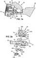
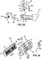
Fig 1b shows an overall view of the shaver ofFig 1 from the back side,Fig 1c shows a cross-section of the shaver ofFig 1 , along line Ic, with the shaver head in the neutral positionFig 1d shows a cross-section of the shaver ofFig 1 , along line Ic, with the shaver head in the neutral position, with a button rotated,Fig 1e shows a cross-section of the shaver ofFig 1 , along line Ic, with the shaver head in a rotated positionFigs 2a and2b are two exploded perspective views of head attachment mechanism of the handle of the shaver ofFig 1 , viewed in two directions,Fig 2c is a top exploded view of the head attachment mechanism,Fig 2d is a side exploded view of the head attachment mechanism,Fig 3a shows the shaver head and the cartridge of the shaver ofFig 1 , as seen from the back,Fig 3b shows a cross-section of the shaver head with the cartridge inserted,Fig 4 shows a detail side view of the cartridge,Fig 5a is a front view of the shaver head, andFig 5b is a back view of the shaver head.- On the different Figures, the same reference signs designate like or similar elements.
Figs 1a to 1c show an example of a shaver according to the present invention. The shaver comprises ahandle 20, ashaver head 40 and acartridge 60, which accommodates one ormore blades 63. On the example shown on the Figures, there are four blades. However, the cartridge may also use more or less of blades.- The cartridge 60 (
Figs 3a and4 ) is formed as a frame with atop wall 61, twolateral walls 62,bottom wall 67 and a back structure (seen onFig 4 ). Thetop wall 61 and thebottom wall 67 are elongated and connected by thelateral walls 62. The frame of thecartridge 60 may be molded out of plastic; preferably, the frame is one-piece. Theblades 63 extend between thelateral walls 62, parallel to thetop wall 61 and thebottom wall 67. Theblades 63 may be made from bent sheet metal, or, preferably, they may be straight and supported with blade supports 63A. Theblades 63 and/or the blade supports 63A are then accommodated in seats 63B provided in thelateral walls 62. Moreover, the blades may for instance be placed movably. Thelateral walls 62 may be provided withelastic fingers 64, extending towards the insides of the cartridge frame, in a direction parallel to theblades 63, and supporting movably theblades 63. Theblades 63 may be held in thecartridge 60 by a pair of bent metal strips 66, which encircle the ends of theblades 63 and thus hold them in place. The number of blades may be for example four. In thetop wall 61, lying generally in a plane defined by the blade edges, a shavingaid 61A may be provided. In other embodiments, the blades may be fixed. - The
handle 20 has an elongated handgrip portion (not shown) which may be provided with features that enhance grip of the user and help prevent slipping, such as ribs, pegs, elastomeric parts and the like. Thehandle 20 is preferably molded out of a plastic material. Thehandle 20 is terminated in twoyokes 21 extending from the handle, as shown onFig 2 . Theyokes 21 end in a mounting portion, provided in a form ofshell bearings 22. Theshell bearings 22 cooperate withcomplementary depressions 41 provided on theshaver head 40. Theshell bearings 22 and thecomplementary depressions 41 together enable theshaver head 40 to pivot about an axis parallel to the length of theblades 63. Alternatively, theshell bearings 22 may be replaced by hinges, pins or other pivoting means. - The
yokes 21 further define acavity 25, accommodating a button 30 (will be described later). Thecavity 25 further comprises agap 23, positioned between theyokes 21. Thegap 23 accommodates acam follower 24. - In an embodiment shown on
Figs 2a to 2d , thecam follower 24 comprises a cylinder-like body. The cylinder-like body defines a rotational axis. The rotational axis is parallel to the pivoting axis defined by theshell bearings 22. In a direction of the rotational axis, from the opposing bases of the cylinder-like body, a pair ofpegs 24B protrude. In a plane generally perpendicular to the rotational axis, abeak 24A projects. Thebeak 24A is preferably bent to form a convex projection. When thecam follower 24 is assembled to thehandle 20, thebeak 24A projects towards the shaving plane and is bent upwards, towards theshaver head 40. Thebeak 24A cooperates with a rest 43 provided on the back wall of theshaver head 40, therefore enabling theshaver head 40 to be returned to the neutral position. The cylinder-like body of thecam follower 24 further comprises adepression 24C. Thedepression 24C accommodates aleaf spring 36. Theleaf spring 36 is adapted to provide a return force for thecam follower 24, and thus facilitates the returning of theshaver head 40 to the neutral position. - The
leaf spring 36 may be provided in a form of a generally E-shaped body, as shown onFigs 2a to 2d . Theleaf spring 36 comprises threebranches base portion 36C. Theouter branches 36B are provided with an elongated ends, the ends being bent at approximately 90 degrees with respect to thebase portion 36C; preferably, the angle is less than 90 degrees but more than 80 degrees. Thebranches 36B are thus substantially L-shaped. Themiddle branch 36A is bent in the same direction as theouter branches 36B. Preferably, the angle at which the middle branch is bent is obtuse. Preferably, themiddle branch 36A is shorter than theouter branches 36B. Theleaf spring 36 is positioned so as to have themiddle branch 36A positioned in thedepression 24C. An example onFigs 1c and1e shows a position of thehead 40 and thecam follower 24 in the neutral position and in rotated position, respectively. In this example, when thehead 40 is rotated, thebeak 24A of thecam follower 24 is moved downwards in a direction away from thebutton 30, themiddle branch 36A of theleaf spring 36 is bent upwards in a direction towards the button by a bottom wall of thecavity 24C, and thus put under tension. When a force is removed, themiddle branch 36A of theleaf spring 36 provides a return force for thecam follower 24. - When the
leaf spring 36 is inserted into thecavity 25, it is held in place by a pair ofribs 35. Theribs 35 protrude in the insides of thecavity 25 and are preferably positioned adjacent the bottom part of thecavity 25. Theribs 35 at least partially overlap theouter branches 36B of theleaf spring 36, thus holding theleaf spring 36 inside of thecavity 25. Theleaf spring 36 is preferably made of metal. Theleaf spring 36 may be also made of any suitable material, such as plastic or material with elastic properties. - An example of a
shaver head 40 is shown onFigs 3a ,3b ,5a and 5b . The shaver head comprises afront wall 44, aback structure 48, abottom wall 46 andlateral walls 42. Thefront wall 44 may include a skin engaging element or a guard, preferably made in an elastomeric material. Theback wall 43 comprisesdepressions 41, which accommodateshell bearings 22, positioned at the end of thehandle 20. Theback structure 48 comprises a rest 43, cooperating with thecam follower 24. - The
shaver head 40 forms a seating where thecartridge 60 can be accommodated (detail of such seating is shown onFig 5a ). Thecartridge 60 is preferably inserted from a direction perpendicular to the shaving plane. - Once the
cartridge 60 is inserted into theshaver head 40, it encounters aspring 45, positioned in theback structure 48 of theshaver head 40. Thespring 45 can be seen onFigs 3a and3b . In the example shown on the Figures, thespring 45 is omega-shaped. Thespring 45 comprisesend portions 45A and snap-fittingportions 45B. - The
back structure 48 of theshaver head 40 comprises a holding portion, adapted to hold thespring 45 in place. In an example shown on the Figures, the holding portion comprises anupper holder 48A, and a pair oflower holders 48B. Theholders shaver head 40 in a direction away from the shaving plane. Theholders spring 45 so that movements of thespring 45 are minimized. Theend portions 45A of thespring 45 are inserted into thelower holders 48B. The snap-fitting portion 45B is inserted into theupper holder 48A. - The
back structure 48 of theshaver head 45 further comprises anaperture 48C. Theaperture 48C is preferably positioned between theholders spring 45 is inserted into theholders spring 45 and theaperture 48C are aligned so that they form a passage. - Between the
lower holders 48B, therest 43 for thecam follower 24 may also be positioned. - The back structure of the
cartridge 60 is provided with aholder 65, which can be encountered by the snap-fitting portion 45B of thespring 45. An example of a holder is shown onFigs 3a ,3b and 4 . Theholder 65 preferably protrudes from thecartridge 60 in a direction away from the shaving plane. Theholder 65 is preferably provided as a cylinder-shaped body. The cylinder-shaped body preferably has a circular cross-section. Alternatively, the cylinder-shaped body may have a cross-section of any suitable shape such as a rectangle, a triangle, an ellipse and the like. The cylinder-shaped body may be provided hollow in order to save material and also improve elasticity of theholder 65. Theholder 65 is preferably provided with agroove 65A. The groove is preferably positioned in one third to one half of the length of theholder 65. - Once the
cartridge 60 is inserted, theholder 65 is encountered by the snap-fitting portion 45B of thespring 45, the snap-fitting portion 45B of thespring 45 holds theholder 65 of thecartridge 60, and thus thecartridge 60 is retained in its seating in theshaver head 40. As the seating provided on theshaver head 40 spans along the whole length of thecartridge 60, unwanted rotation of the cartridge is reduced. - The
spring 45 is preferably made of metal, therefore being resilient and not easily destroyed, but may be made in any other suitable elastic material. - Once the
cartridge 60 is inserted into theshaver head 40, thecartridge 60 preferably does not perform any movements with respect to theshaver head 40. Theshaver head 40 is attached pivotally to thehandle 20; preferably, the pivoting means 22, 41 are provided on theshaver head 40 and on thehandle 20, but not on thecartridge 60. - The above described mechanism, which uses the
spring 45 provided on theshaver head 40 and theholder 65 provided on thecartridge 60, brings about several advantages. The only replaced component is thecartridge 60, which in itself does not hold any additional features (such as pivoting means and the like). Therefore the price of thecartridge 60 may be lowered and the manufacturing process thereof may be simplified; as theshaver head 40 and thehandle 20 are not replaced, they may be manufactured as being more robust while keeping the price reasonable. Especially, the means provided to secure the pivoting attachment of theshaver head 40 to thehandle 20, may be made more reliable. Moreover, the snap-fitting mechanism is both easy to manufacture and easy to operate. Moreover, there is only onespring 45 provided, which may further reduce costs. - The top part of the
handle 20 adjacent theshaver head 40 is also provided with abutton 30. An example of thebutton 30 may be seen onFig 1b ,1c and2a to 2d . Thebutton 30 is provided in a form of a generally box-shaped body which has afront end 30A and aback end 30B. From thefront end 30A, apusher 31 protrudes. Thepusher 31 protrudes generally in a direction of the shaving plane. - From the body of the
button 30, towards thehandle 20, two pairs ofarms front arms 33 are positioned at thefront end 30A of thebutton 30. Theback arms 34 are positioned at theback end 30B of thebutton 30. At the ends offront arms 33, pegs 33A are positioned. Thepegs 33A preferably protrude outwardly from thefront arms 33. The ends of thefront arms 33 also comprisedepressions 33B. Thedepressions 33B are adapted to accommodate thepegs 24B, which are provided on thecam follower 24. - The
button 30 is adapted to be rotated. To facilitate its rotation, thecavity 25 formed between theyokes 21 of thehandle 20 is provided with a pair ofdepressions 26. Thedepressions 26 are positioned symmetrically at the walls of thecavity 25. Thedepressions 26 accommodate thepegs 33A, provided on thearms 33 of the button 3. When thepegs 33A are inserted intodepressions 26, thebutton 30 can be rotated about an axis established by thepegs 33A. - To ensure the
button 30 to be returned to its initial position after being rotated, theleaf spring 36 is provided. Theleaf spring 36 is positioned in thecavity 25. Theleaf spring 36 is positioned so that thebranches outer branches 36B are bent upwards, towards thebutton 30. Theouter branches 36B are positioned facing afront surface 33C of thefront arms 33 of thebutton 30. When thebutton 30 is rotated (as shown onFig 1d ), theelongated branches 36B of theleaf spring 36 are placed under tension. When the force rotating thebutton 30 is removed, theelongated branches 36B return thebutton 30 to its initial position. Thebutton 30 also comprises theback arms 34, which ensure that thebutton 30 is not moved further behind its initial position. - The
leaf spring 36 also provides a return force for thecam follower 24. In the embodiment shown on the Figures, thecam follower 24 is inserted into the space formed between thefront arms 33 of thebutton 30. Thepegs 24B of thecam follower 24 are accommodated in thedepressions 33B of thefront arms 33 of thebutton 30, thus allowing the cam follower to be rotated. Theleaf spring 36 is then positioned so as to have itsmiddle branch 36A inserted into thedepression 24C of thecam follower 24. When thecam follower 24 is rotated, a wall of thedepression 24C bends themiddle branch 36A of theleaf spring 36. When the force rotating thecam follower 24 is removed, themiddle branch 36A of theleaf spring 36 provides a return force for thecam follower 24. - The
button 30 further comprises afinger rest area 32. When the user wishes to disengage thecartridge 60 from theshaver head 40, s/he pushes thebutton 30. Under the pressure, thebutton 30 rotates. When thebutton 30 is rotated (as can be seen onFig 1d ), thepusher 31 encounters theholder 65 of thecartridge 60 and pushes theholder 65. When thepusher 31 pushes theholder 65, thegroove 65A is disengaged from the snap-fitting portion 45B of thespring 45 and thus thecartridge 65 is disengaged. In this way, the user does not have to touch thecartridge 60 by his/her fingers and the risk of cutting the user's fingers with theblades 63 is then reduced. - The above described mechanism brings about several advantages. The
button 30 as well as thecam follower 24 are simplified, and the number of parts needed is reduced. Therefore, the reliability is increased, the assembly process is simplified and the costs are reduced. The rotating movement of thebutton 30 is easily achieved, and thus the operation of thebutton 30 is simplified. When thecartridge 60 is disengaged, theyokes 21 are not moved, which helps prevent their overload and subsequent damage. When thebutton 30 is pushed, thecam follower 24 does not move, thus the overload of thecam follower 24 is reduced and the reliability is increased. Moreover, when using a rotating movement of thebutton 30, it is possible to apply the release force to a more precise position, namely to the position when thecartridge 60 is attached, thus achieving higher efficiency of thebutton 30. In fact, in the shavers known in the art, especially the one-way pivoting shavers, the pivoting axis is usually located approximately at the position of the first blade of the cartridge. The position of the handle and the pivot location cause conflicting vector relations that do not support an efficient push force of the button if a sliding button is used. By using therotating button 30, the application of the push/release force is closer to the optimum location. Thus, the efficiency of the release button function is enhanced. - To prevent the
cam follower 24 or thebutton 30 from disengaging, thepegs 24B of thecam follower 24 and thepegs 33A of the button are provided in a rectangular shape. In this way, thepegs depressions handle 20 are assembled together. - Moreover, when the components of the
handle 20 such as thebutton 30 and thecam follower 24 are assembled together, they prevent theyokes 21 from being accidentally moved closer together. When theyokes 21 cannot be moved closer together, the risk of the yokes accidentally releasing the shaver head as a whole is reduced, thus reducing risk of injury of the user.
Claims (15)
- A shaver comprising:a handle (20) with an elongated handgrip portion and a mounting portion (22),a shaver head (40), the shaver head (40) being pivotally attached to the mounting portion (22),a removable cartridge (60), the cartridge (60) comprising at least one blade (63), the cartridge (60) being adapted to be attached to the shaver head (40) and removed from the shaver head (40),a spring (45) provided on the shaver head (40), the spring (45) being adapted to attach the cartridge (60) to the shaver head (40), andcharacterized in that the shaver further comprises a pusher (31), adapted to encounter the cartridge (60) to release the cartridge (60) from the shaver head (40),wherein the spring (45) comprises at least one part which forms a loop.
- A shaver as in claim 1, wherein the shaver head (40) further comprises a back structure (48), and wherein the spring (45) is attached to the back structure (48) of the shaver head (40).
- A shaver as in claims 1 or 2, wherein the cartridge (60) is ejected in a direction perpendicular to the direction of shaving.
- A shaver as in any of the preceding claims, wherein the spring (45) is made of a curved wire.
- A shaver as in claim 4, wherein the spring (45) is omega-shaped.
- A shaver as in any previous claim, wherein the spring (45) is made of metal.
- A shaver as in any of the preceding claims, wherein the shaver head (40) further comprises a bottom wall (46) and a guard member (44), the guard member (44) being positioned adjacent the bottom wall (46).
- A shaver as in any of the preceding claims, wherein the cartridge (60) comprises a holder (65), the holder (65) being provided in a form of a cylinder-shaped body, the holder (65) being adapted to cooperate with the spring (45).
- A shaver as in claim 8, wherein the holder (65) comprises a groove (65A), the groove (65A) being adapted to cooperate with the loop formed by the spring (45).
- A shaver as in any of the preceding claims, wherein the handle (20) further comprises a rotating button (30), and wherein the button (30) further comprises the pusher (31), the pusher (31) being adapted to encounter the holder (65) of the cartridge (60) and thus release the cartridge (60) from the shaver head (40).
- A shaver as in any one of claims 1-10, wherein the at least one blade (63) is mounted movably.
- A shaver as in any one of claims 1-11, wherein the cartridge (60) further comprises a top wall (61) and a shaving aid (61A), the shaving aid (61A) positioned in the top wall (61).
- A head and handle assembly for a shaver as claimed in any of claims 1 to 12, the head and handle assembly comprising:a handle (20) with an elongated handgrip portion and a mounting portion (22),a shaver head (40), the shaver head (40) being pivotally attached to the mounting portion (22), the shaver head (40) being adapted to receive a removeable cartridge (60),a spring (45) provided on the shaver head (40), the spring (45) being adapted to attach a cartridge (60) to the shaver head (40),characterized in that the assembly further comprises a pusher (31), adapted to encounter the cartridge (60) to release the cartridge (60) from the shaver head (40),wherein the spring (45) comprises at least one part which forms a loop.
- An assembly as in claim 13, wherein the shaver head (40) further comprises a back structure (48), and wherein the spring (45) is a leaf spring and is attached to the back structure (48).
- An assembly as in any of claims 13 or 14, wherein the spring (45) is made of a curved wire, and wherein the spring (45) is omega-shaped.
Applications Claiming Priority (1)
| Application Number | Priority Date | Filing Date | Title |
|---|---|---|---|
| PCT/EP2012/076807WO2014094909A1 (en) | 2012-12-21 | 2012-12-21 | Shaver |
Publications (2)
| Publication Number | Publication Date |
|---|---|
| EP2934825A1 EP2934825A1 (en) | 2015-10-28 |
| EP2934825B1true EP2934825B1 (en) | 2017-12-20 |
Family
ID=47522612
Family Applications (1)
| Application Number | Title | Priority Date | Filing Date |
|---|---|---|---|
| EP12813024.2AActiveEP2934825B1 (en) | 2012-12-21 | 2012-12-21 | Shaver |
Country Status (9)
| Country | Link |
|---|---|
| US (1) | US9707688B2 (en) |
| EP (1) | EP2934825B1 (en) |
| JP (1) | JP6113301B2 (en) |
| KR (1) | KR102009179B1 (en) |
| CN (1) | CN104870149B (en) |
| BR (1) | BR112015013757B1 (en) |
| CA (1) | CA2894464A1 (en) |
| MX (1) | MX361581B (en) |
| WO (1) | WO2014094909A1 (en) |
Families Citing this family (52)
| Publication number | Priority date | Publication date | Assignee | Title |
|---|---|---|---|---|
| KR100749925B1 (en) | 2006-06-29 | 2007-08-16 | 주식회사 도루코 | Shaver |
| US9283685B2 (en) | 2012-07-26 | 2016-03-15 | Shavelogic, Inc. | Pivoting razors |
| US9486930B2 (en) | 2012-09-27 | 2016-11-08 | Shavelogic, Inc. | Shaving systems |
| WO2014051842A1 (en)* | 2012-09-27 | 2014-04-03 | Shavelogic, Inc. | Shaving systems |
| WO2014051843A1 (en) | 2012-09-28 | 2014-04-03 | Shavelogic, Inc. | Shaving systems |
| US9623575B2 (en) | 2012-12-18 | 2017-04-18 | Shavelogic, Inc. | Shaving systems |
| JP6053955B2 (en)* | 2012-12-21 | 2016-12-27 | ビック・バイオレクス・エス・エー | Shaver with replaceable cartridge, cartridge and head handle assembly for such a shaver |
| US9694503B2 (en)* | 2012-12-21 | 2017-07-04 | Bic Violex S.A. | Shaver with interchangeable cartridge, cartridge and head and handle assembly for such shaver |
| EP2934826B1 (en)* | 2012-12-21 | 2017-12-13 | BIC-Violex S.A. | Shaver |
| US20150158192A1 (en) | 2013-12-09 | 2015-06-11 | Shavelogic, Inc. | Multi-material pivot return for shaving systems |
| WO2015142663A1 (en)* | 2014-03-21 | 2015-09-24 | Shavelogic, Inc. | Metal spring return |
| EP2962815A1 (en)* | 2014-07-02 | 2016-01-06 | The Gillette Company | Shaving razor pivot lock |
| EP3385043B1 (en)* | 2014-10-10 | 2022-06-08 | Edgewell Personal Care Brands, LLC | Universal razor cartridge handle |
| MX394064B (en)* | 2014-12-05 | 2025-03-24 | Bic Violex Sa | A SHAVER HANDLE WITH A LOCKING AND RELEASE MECHANISM FOR ATTACHING AND DETACHING A RAKE CARTRIDGE. |
| EP3378613B1 (en)* | 2015-11-20 | 2021-08-11 | Dorco Co., Ltd. | Razor handle assembly and razor comprising same |
| RU2694395C1 (en) | 2015-12-01 | 2019-07-12 | Бик-Виолекс Са | Shaving machines and cartridges |
| EP3389961B1 (en)* | 2015-12-17 | 2021-08-11 | BIC Violex S.A. | Shaving head |
| CA3018095A1 (en) | 2016-03-18 | 2017-09-21 | Personal Care Marketing And Research, Inc. | Razor cartridge |
| CN109803801B (en)* | 2016-08-18 | 2022-02-08 | 徽章知识产权控股公司 | shaving device |
| USD816911S1 (en)* | 2016-10-07 | 2018-05-01 | Personal Care Marketing and Research International | Razor docking mechanism |
| KR101774370B1 (en)* | 2016-11-21 | 2017-09-04 | 주식회사 도루코 | Razor |
| US9993931B1 (en)* | 2016-11-23 | 2018-06-12 | Personal Care Marketing And Research, Inc. | Razor docking and pivot |
| EP3348363B1 (en) | 2017-01-17 | 2019-07-24 | BIC-Violex S.A. | A shaving handle system for holding a cartridge pivotable about two axes |
| EP3348364B1 (en) | 2017-01-17 | 2020-04-15 | BIC-Violex S.A. | A handle for a shaver enabling rotational movement of a cartridge |
| CN110248779B (en)* | 2017-01-17 | 2021-10-22 | 比克维奥莱克斯公司 | Connector suitable for a wet shaving head pivotable about two axes |
| US10543611B2 (en)* | 2017-04-14 | 2020-01-28 | Bic-Violex Sa | Head converter |
| MX2020000759A (en)* | 2017-07-20 | 2020-08-17 | Shavelogic Inc | Shaving systems. |
| KR101876233B1 (en)* | 2017-09-29 | 2018-07-10 | 주식회사 도루코 | Razor cartridge assembly |
| WO2019108392A1 (en)* | 2017-11-28 | 2019-06-06 | Edgewell Personal Care Brands, Llc | Razor handle |
| JP2021515672A (en) | 2018-03-30 | 2021-06-24 | ザ ジレット カンパニー リミテッド ライアビリティ カンパニーThe Gillette Company Llc | Razor system for shaving |
| US10773408B2 (en)* | 2018-03-30 | 2020-09-15 | The Gillette Company Llc | Shaving razor cartridge |
| EP3774215B1 (en) | 2018-03-30 | 2024-03-13 | The Gillette Company LLC | Razor handle with a pivoting portion |
| EP3774221A1 (en) | 2018-03-30 | 2021-02-17 | The Gillette Company LLC | Razor handle with a pivoting portion |
| US12434399B2 (en) | 2018-03-30 | 2025-10-07 | The Gillette Company Llc | Razor assembly with loop shaped spring member |
| USD874061S1 (en) | 2018-03-30 | 2020-01-28 | The Gillette Company Llc | Shaving razor cartridge |
| WO2019191163A1 (en) | 2018-03-30 | 2019-10-03 | The Gillette Company Llc | Razor handle with a pivoting portion |
| US11607820B2 (en) | 2018-03-30 | 2023-03-21 | The Gillette Company Llc | Razor handle with movable members |
| EP3546156B1 (en) | 2018-03-30 | 2021-03-10 | The Gillette Company LLC | Razor handle with a pivoting portion |
| CN111801205B (en) | 2018-03-30 | 2022-08-23 | 吉列有限责任公司 | Razor handle with pivoting portion |
| BR112020020132A2 (en) | 2018-03-30 | 2021-01-05 | The Gillette Company Llc | HANDLE OF SHAVING OR DEVILING APPLIANCE WITH MOBILE LIMBS |
| WO2019190962A1 (en) | 2018-03-30 | 2019-10-03 | The Gillette Company Llc | Razor handle with a pivoting portion |
| EP3546159B1 (en) | 2018-03-30 | 2022-08-03 | The Gillette Company LLC | Razor mechanisms |
| CN111819048A (en) | 2018-03-30 | 2020-10-23 | 吉列有限责任公司 | Razor handle with pivoting portion |
| CA3092879A1 (en) | 2018-03-30 | 2019-10-03 | The Gillette Company Llc | Razor handle with movable members |
| EP3774227A1 (en) | 2018-03-30 | 2021-02-17 | The Gillette Company LLC | Razor handle with movable members |
| JP7104168B2 (en) | 2018-03-30 | 2022-07-20 | ザ ジレット カンパニー リミテッド ライアビリティ カンパニー | Razor handle with pivot part |
| USD869767S1 (en)* | 2018-07-17 | 2019-12-10 | The Gillette Company Llc | Razor |
| USD884970S1 (en) | 2019-02-27 | 2020-05-19 | PCMR International Ltd. | Razor cartridge guard |
| USD884971S1 (en) | 2019-02-27 | 2020-05-19 | Pcmr International Ltd | Razor cartridge |
| USD884969S1 (en) | 2019-02-27 | 2020-05-19 | Pcmr International Ltd | Combined razor cartridge guard and docking |
| US11000960B1 (en) | 2020-11-16 | 2021-05-11 | Personal Care Marketing And Research, Inc. | Razor exposure |
| CN216658034U (en)* | 2021-11-03 | 2022-06-03 | 深圳诺泰科电子有限公司 | Shaver |
Citations (2)
| Publication number | Priority date | Publication date | Assignee | Title |
|---|---|---|---|---|
| FR2377256A1 (en)* | 1977-01-17 | 1978-08-11 | Morris Ag | SHAVER |
| US4617736A (en)* | 1984-08-02 | 1986-10-21 | Mccrary Mark W | Swivel headed scraping device |
Family Cites Families (17)
| Publication number | Priority date | Publication date | Assignee | Title |
|---|---|---|---|---|
| GB9125262D0 (en)* | 1991-11-27 | 1992-01-29 | Gillette Co | Razor with blade protection means |
| US5669139A (en)* | 1991-11-27 | 1997-09-23 | The Gillette Company | Razor with blade protection means |
| EP0667813B1 (en)* | 1992-11-09 | 1998-04-15 | Warner-Lambert Company | Insert molded dynamic shaving system |
| EP1099896A3 (en)* | 1999-11-10 | 2003-05-21 | Georg Fischer Haustechnik AG | Connecting device for fluid conduits |
| EP1308250A1 (en)* | 2001-11-01 | 2003-05-07 | Warner-Lambert Company | Razor assembly with replaceable cartridge |
| JP3833171B2 (en)* | 2001-12-21 | 2006-10-11 | ファイザー・プロダクツ・インク | Razor device |
| ATE375850T1 (en)* | 2003-02-25 | 2007-11-15 | Eveready Battery Inc | SHAVER |
| GB2406537B (en)* | 2003-07-21 | 2006-09-06 | Gillette Co | Safety razors |
| US7690122B2 (en)* | 2004-03-11 | 2010-04-06 | The Gillette Company | Shaving razor with button |
| US8033023B2 (en)* | 2004-10-20 | 2011-10-11 | The Gillette Company | Shaving razors and cartridges |
| JP4921747B2 (en) | 2005-09-09 | 2012-04-25 | 株式会社貝印刃物開発センター | razor |
| GB0716941D0 (en) | 2007-08-31 | 2007-10-10 | Knowledge & Merchandising Inc | Razor handle |
| GB2461054A (en)* | 2008-06-18 | 2009-12-23 | Knowledge & Merchandising Inc | Razor handle with predetermined spring index |
| CA2737995C (en)* | 2008-10-01 | 2015-04-07 | Dimitris Efthimiadis | Razor handles to be releasably connected to shaving cartridges and razors including such handles |
| GB2471676B (en)* | 2009-07-07 | 2012-09-05 | Omer Aydin | Razor assembly |
| JP5860707B2 (en)* | 2011-05-18 | 2016-02-16 | 株式会社貝印刃物開発センター | Swing razor |
| GB2507971A (en)* | 2012-11-14 | 2014-05-21 | King Of Shaves Company Ltd | Razor with releasably attachable disposable cartridge |
- 2012
- 2012-12-21MXMX2015008102Apatent/MX361581B/enactiveIP Right Grant
- 2012-12-21JPJP2015548238Apatent/JP6113301B2/enactiveActive
- 2012-12-21BRBR112015013757-1Apatent/BR112015013757B1/enactiveIP Right Grant
- 2012-12-21WOPCT/EP2012/076807patent/WO2014094909A1/enactiveApplication Filing
- 2012-12-21EPEP12813024.2Apatent/EP2934825B1/enactiveActive
- 2012-12-21USUS14/648,305patent/US9707688B2/ennot_activeExpired - Fee Related
- 2012-12-21KRKR1020157019706Apatent/KR102009179B1/enactiveActive
- 2012-12-21CACA2894464Apatent/CA2894464A1/ennot_activeAbandoned
- 2012-12-21CNCN201280077838.XApatent/CN104870149B/enactiveActive
Patent Citations (2)
| Publication number | Priority date | Publication date | Assignee | Title |
|---|---|---|---|---|
| FR2377256A1 (en)* | 1977-01-17 | 1978-08-11 | Morris Ag | SHAVER |
| US4617736A (en)* | 1984-08-02 | 1986-10-21 | Mccrary Mark W | Swivel headed scraping device |
Also Published As
| Publication number | Publication date |
|---|---|
| US20150290819A1 (en) | 2015-10-15 |
| MX2015008102A (en) | 2015-11-06 |
| BR112015013757B1 (en) | 2021-10-13 |
| CN104870149A (en) | 2015-08-26 |
| BR112015013757A2 (en) | 2017-07-11 |
| JP2016500315A (en) | 2016-01-12 |
| EP2934825A1 (en) | 2015-10-28 |
| KR20150095935A (en) | 2015-08-21 |
| CN104870149B (en) | 2017-06-30 |
| KR102009179B1 (en) | 2019-08-09 |
| MX361581B (en) | 2018-12-11 |
| US9707688B2 (en) | 2017-07-18 |
| JP6113301B2 (en) | 2017-04-12 |
| CA2894464A1 (en) | 2014-06-26 |
| WO2014094909A1 (en) | 2014-06-26 |
Similar Documents
| Publication | Publication Date | Title |
|---|---|---|
| EP2934825B1 (en) | Shaver | |
| EP2934826B1 (en) | Shaver | |
| EP2934829B1 (en) | Shaver | |
| EP2934824B1 (en) | Shaver | |
| EP2934828B1 (en) | Shaver with interchangeable cartridge and head and handle assembly for such shaver | |
| CN106660223B (en) | Handle capable of detachably connecting shaver with knife rest |
Legal Events
| Date | Code | Title | Description |
|---|---|---|---|
| PUAI | Public reference made under article 153(3) epc to a published international application that has entered the european phase | Free format text:ORIGINAL CODE: 0009012 | |
| 17P | Request for examination filed | Effective date:20150528 | |
| AK | Designated contracting states | Kind code of ref document:A1 Designated state(s):AL AT BE BG CH CY CZ DE DK EE ES FI FR GB GR HR HU IE IS IT LI LT LU LV MC MK MT NL NO PL PT RO RS SE SI SK SM TR | |
| AX | Request for extension of the european patent | Extension state:BA ME | |
| DAX | Request for extension of the european patent (deleted) | ||
| 17Q | First examination report despatched | Effective date:20160913 | |
| STAA | Information on the status of an ep patent application or granted ep patent | Free format text:STATUS: EXAMINATION IS IN PROGRESS | |
| GRAP | Despatch of communication of intention to grant a patent | Free format text:ORIGINAL CODE: EPIDOSNIGR1 | |
| STAA | Information on the status of an ep patent application or granted ep patent | Free format text:STATUS: GRANT OF PATENT IS INTENDED | |
| INTG | Intention to grant announced | Effective date:20170926 | |
| GRAS | Grant fee paid | Free format text:ORIGINAL CODE: EPIDOSNIGR3 | |
| GRAA | (expected) grant | Free format text:ORIGINAL CODE: 0009210 | |
| STAA | Information on the status of an ep patent application or granted ep patent | Free format text:STATUS: THE PATENT HAS BEEN GRANTED | |
| AK | Designated contracting states | Kind code of ref document:B1 Designated state(s):AL AT BE BG CH CY CZ DE DK EE ES FI FR GB GR HR HU IE IS IT LI LT LU LV MC MK MT NL NO PL PT RO RS SE SI SK SM TR | |
| REG | Reference to a national code | Ref country code:GB Ref legal event code:FG4D Ref country code:FR Ref legal event code:PLFP Year of fee payment:6 | |
| REG | Reference to a national code | Ref country code:CH Ref legal event code:EP | |
| REG | Reference to a national code | Ref country code:IE Ref legal event code:FG4D | |
| REG | Reference to a national code | Ref country code:AT Ref legal event code:REF Ref document number:955942 Country of ref document:AT Kind code of ref document:T Effective date:20180115 | |
| REG | Reference to a national code | Ref country code:DE Ref legal event code:R096 Ref document number:602012041174 Country of ref document:DE | |
| REG | Reference to a national code | Ref country code:NL Ref legal event code:FP | |
| PG25 | Lapsed in a contracting state [announced via postgrant information from national office to epo] | Ref country code:SE Free format text:LAPSE BECAUSE OF FAILURE TO SUBMIT A TRANSLATION OF THE DESCRIPTION OR TO PAY THE FEE WITHIN THE PRESCRIBED TIME-LIMIT Effective date:20171220 Ref country code:LT Free format text:LAPSE BECAUSE OF FAILURE TO SUBMIT A TRANSLATION OF THE DESCRIPTION OR TO PAY THE FEE WITHIN THE PRESCRIBED TIME-LIMIT Effective date:20171220 Ref country code:FI Free format text:LAPSE BECAUSE OF FAILURE TO SUBMIT A TRANSLATION OF THE DESCRIPTION OR TO PAY THE FEE WITHIN THE PRESCRIBED TIME-LIMIT Effective date:20171220 Ref country code:NO Free format text:LAPSE BECAUSE OF FAILURE TO SUBMIT A TRANSLATION OF THE DESCRIPTION OR TO PAY THE FEE WITHIN THE PRESCRIBED TIME-LIMIT Effective date:20180320 | |
| REG | Reference to a national code | Ref country code:LT Ref legal event code:MG4D | |
| REG | Reference to a national code | Ref country code:AT Ref legal event code:MK05 Ref document number:955942 Country of ref document:AT Kind code of ref document:T Effective date:20171220 | |
| PG25 | Lapsed in a contracting state [announced via postgrant information from national office to epo] | Ref country code:RS Free format text:LAPSE BECAUSE OF FAILURE TO SUBMIT A TRANSLATION OF THE DESCRIPTION OR TO PAY THE FEE WITHIN THE PRESCRIBED TIME-LIMIT Effective date:20171220 Ref country code:LV Free format text:LAPSE BECAUSE OF FAILURE TO SUBMIT A TRANSLATION OF THE DESCRIPTION OR TO PAY THE FEE WITHIN THE PRESCRIBED TIME-LIMIT Effective date:20171220 Ref country code:HR Free format text:LAPSE BECAUSE OF FAILURE TO SUBMIT A TRANSLATION OF THE DESCRIPTION OR TO PAY THE FEE WITHIN THE PRESCRIBED TIME-LIMIT Effective date:20171220 Ref country code:BG Free format text:LAPSE BECAUSE OF FAILURE TO SUBMIT A TRANSLATION OF THE DESCRIPTION OR TO PAY THE FEE WITHIN THE PRESCRIBED TIME-LIMIT Effective date:20180320 | |
| REG | Reference to a national code | Ref country code:GR Ref legal event code:EP Ref document number:20180400324 Country of ref document:GR Effective date:20180518 | |
| PG25 | Lapsed in a contracting state [announced via postgrant information from national office to epo] | Ref country code:SK Free format text:LAPSE BECAUSE OF FAILURE TO SUBMIT A TRANSLATION OF THE DESCRIPTION OR TO PAY THE FEE WITHIN THE PRESCRIBED TIME-LIMIT Effective date:20171220 Ref country code:CZ Free format text:LAPSE BECAUSE OF FAILURE TO SUBMIT A TRANSLATION OF THE DESCRIPTION OR TO PAY THE FEE WITHIN THE PRESCRIBED TIME-LIMIT Effective date:20171220 Ref country code:EE Free format text:LAPSE BECAUSE OF FAILURE TO SUBMIT A TRANSLATION OF THE DESCRIPTION OR TO PAY THE FEE WITHIN THE PRESCRIBED TIME-LIMIT Effective date:20171220 Ref country code:CY Free format text:LAPSE BECAUSE OF FAILURE TO SUBMIT A TRANSLATION OF THE DESCRIPTION OR TO PAY THE FEE WITHIN THE PRESCRIBED TIME-LIMIT Effective date:20171220 Ref country code:ES Free format text:LAPSE BECAUSE OF FAILURE TO SUBMIT A TRANSLATION OF THE DESCRIPTION OR TO PAY THE FEE WITHIN THE PRESCRIBED TIME-LIMIT Effective date:20171220 | |
| REG | Reference to a national code | Ref country code:CH Ref legal event code:PL | |
| PG25 | Lapsed in a contracting state [announced via postgrant information from national office to epo] | Ref country code:IS Free format text:LAPSE BECAUSE OF FAILURE TO SUBMIT A TRANSLATION OF THE DESCRIPTION OR TO PAY THE FEE WITHIN THE PRESCRIBED TIME-LIMIT Effective date:20180420 Ref country code:IT Free format text:LAPSE BECAUSE OF FAILURE TO SUBMIT A TRANSLATION OF THE DESCRIPTION OR TO PAY THE FEE WITHIN THE PRESCRIBED TIME-LIMIT Effective date:20171220 Ref country code:RO Free format text:LAPSE BECAUSE OF FAILURE TO SUBMIT A TRANSLATION OF THE DESCRIPTION OR TO PAY THE FEE WITHIN THE PRESCRIBED TIME-LIMIT Effective date:20171220 Ref country code:SM Free format text:LAPSE BECAUSE OF FAILURE TO SUBMIT A TRANSLATION OF THE DESCRIPTION OR TO PAY THE FEE WITHIN THE PRESCRIBED TIME-LIMIT Effective date:20171220 Ref country code:AT Free format text:LAPSE BECAUSE OF FAILURE TO SUBMIT A TRANSLATION OF THE DESCRIPTION OR TO PAY THE FEE WITHIN THE PRESCRIBED TIME-LIMIT Effective date:20171220 Ref country code:PL Free format text:LAPSE BECAUSE OF FAILURE TO SUBMIT A TRANSLATION OF THE DESCRIPTION OR TO PAY THE FEE WITHIN THE PRESCRIBED TIME-LIMIT Effective date:20171220 | |
| REG | Reference to a national code | Ref country code:IE Ref legal event code:MM4A | |
| REG | Reference to a national code | Ref country code:DE Ref legal event code:R097 Ref document number:602012041174 Country of ref document:DE | |
| PG25 | Lapsed in a contracting state [announced via postgrant information from national office to epo] | Ref country code:MT Free format text:LAPSE BECAUSE OF NON-PAYMENT OF DUE FEES Effective date:20171221 Ref country code:MC Free format text:LAPSE BECAUSE OF FAILURE TO SUBMIT A TRANSLATION OF THE DESCRIPTION OR TO PAY THE FEE WITHIN THE PRESCRIBED TIME-LIMIT Effective date:20171220 Ref country code:LU Free format text:LAPSE BECAUSE OF NON-PAYMENT OF DUE FEES Effective date:20171221 | |
| REG | Reference to a national code | Ref country code:BE Ref legal event code:MM Effective date:20171231 | |
| PLBE | No opposition filed within time limit | Free format text:ORIGINAL CODE: 0009261 | |
| STAA | Information on the status of an ep patent application or granted ep patent | Free format text:STATUS: NO OPPOSITION FILED WITHIN TIME LIMIT | |
| PG25 | Lapsed in a contracting state [announced via postgrant information from national office to epo] | Ref country code:IE Free format text:LAPSE BECAUSE OF NON-PAYMENT OF DUE FEES Effective date:20171221 | |
| 26N | No opposition filed | Effective date:20180921 | |
| PG25 | Lapsed in a contracting state [announced via postgrant information from national office to epo] | Ref country code:BE Free format text:LAPSE BECAUSE OF NON-PAYMENT OF DUE FEES Effective date:20171231 Ref country code:DK Free format text:LAPSE BECAUSE OF FAILURE TO SUBMIT A TRANSLATION OF THE DESCRIPTION OR TO PAY THE FEE WITHIN THE PRESCRIBED TIME-LIMIT Effective date:20171220 Ref country code:LI Free format text:LAPSE BECAUSE OF NON-PAYMENT OF DUE FEES Effective date:20171231 Ref country code:CH Free format text:LAPSE BECAUSE OF NON-PAYMENT OF DUE FEES Effective date:20171231 | |
| PG25 | Lapsed in a contracting state [announced via postgrant information from national office to epo] | Ref country code:SI Free format text:LAPSE BECAUSE OF FAILURE TO SUBMIT A TRANSLATION OF THE DESCRIPTION OR TO PAY THE FEE WITHIN THE PRESCRIBED TIME-LIMIT Effective date:20171220 | |
| PG25 | Lapsed in a contracting state [announced via postgrant information from national office to epo] | Ref country code:HU Free format text:LAPSE BECAUSE OF FAILURE TO SUBMIT A TRANSLATION OF THE DESCRIPTION OR TO PAY THE FEE WITHIN THE PRESCRIBED TIME-LIMIT; INVALID AB INITIO Effective date:20121221 | |
| PG25 | Lapsed in a contracting state [announced via postgrant information from national office to epo] | Ref country code:MK Free format text:LAPSE BECAUSE OF FAILURE TO SUBMIT A TRANSLATION OF THE DESCRIPTION OR TO PAY THE FEE WITHIN THE PRESCRIBED TIME-LIMIT Effective date:20171220 | |
| PG25 | Lapsed in a contracting state [announced via postgrant information from national office to epo] | Ref country code:TR Free format text:LAPSE BECAUSE OF FAILURE TO SUBMIT A TRANSLATION OF THE DESCRIPTION OR TO PAY THE FEE WITHIN THE PRESCRIBED TIME-LIMIT Effective date:20171220 | |
| PG25 | Lapsed in a contracting state [announced via postgrant information from national office to epo] | Ref country code:PT Free format text:LAPSE BECAUSE OF FAILURE TO SUBMIT A TRANSLATION OF THE DESCRIPTION OR TO PAY THE FEE WITHIN THE PRESCRIBED TIME-LIMIT Effective date:20171220 | |
| PG25 | Lapsed in a contracting state [announced via postgrant information from national office to epo] | Ref country code:AL Free format text:LAPSE BECAUSE OF FAILURE TO SUBMIT A TRANSLATION OF THE DESCRIPTION OR TO PAY THE FEE WITHIN THE PRESCRIBED TIME-LIMIT Effective date:20171220 | |
| PGFP | Annual fee paid to national office [announced via postgrant information from national office to epo] | Ref country code:NL Payment date:20241121 Year of fee payment:13 | |
| PGFP | Annual fee paid to national office [announced via postgrant information from national office to epo] | Ref country code:DE Payment date:20241121 Year of fee payment:13 | |
| PGFP | Annual fee paid to national office [announced via postgrant information from national office to epo] | Ref country code:GR Payment date:20241122 Year of fee payment:13 | |
| PGFP | Annual fee paid to national office [announced via postgrant information from national office to epo] | Ref country code:GB Payment date:20241122 Year of fee payment:13 | |
| PGFP | Annual fee paid to national office [announced via postgrant information from national office to epo] | Ref country code:FR Payment date:20241121 Year of fee payment:13 |