EP2934347B1 - Applicators for modular magnetic anastomosis device - Google Patents
Applicators for modular magnetic anastomosis deviceDownload PDFInfo
- Publication number
- EP2934347B1 EP2934347B1EP13861506.7AEP13861506AEP2934347B1EP 2934347 B1EP2934347 B1EP 2934347B1EP 13861506 AEP13861506 AEP 13861506AEP 2934347 B1EP2934347 B1EP 2934347B1
- Authority
- EP
- European Patent Office
- Prior art keywords
- applicator
- elongated tube
- elastically deformable
- tube
- arms
- Prior art date
- Legal status (The legal status is an assumption and is not a legal conclusion. Google has not performed a legal analysis and makes no representation as to the accuracy of the status listed.)
- Active
Links
Images


Classifications
- A—HUMAN NECESSITIES
- A61—MEDICAL OR VETERINARY SCIENCE; HYGIENE
- A61B—DIAGNOSIS; SURGERY; IDENTIFICATION
- A61B17/00—Surgical instruments, devices or methods
- A61B17/11—Surgical instruments, devices or methods for performing anastomosis; Buttons for anastomosis
- A61B17/1114—Surgical instruments, devices or methods for performing anastomosis; Buttons for anastomosis of the digestive tract, e.g. bowels or oesophagus
- A—HUMAN NECESSITIES
- A61—MEDICAL OR VETERINARY SCIENCE; HYGIENE
- A61B—DIAGNOSIS; SURGERY; IDENTIFICATION
- A61B17/00—Surgical instruments, devices or methods
- A61B17/34—Trocars; Puncturing needles
- A61B17/3417—Details of tips or shafts, e.g. grooves, expandable, bendable; Multiple coaxial sliding cannulas, e.g. for dilating
- A61B17/3421—Cannulas
- A—HUMAN NECESSITIES
- A61—MEDICAL OR VETERINARY SCIENCE; HYGIENE
- A61B—DIAGNOSIS; SURGERY; IDENTIFICATION
- A61B17/00—Surgical instruments, devices or methods
- A61B17/34—Trocars; Puncturing needles
- A61B17/3468—Trocars; Puncturing needles for implanting or removing devices, e.g. prostheses, implants, seeds, wires
- A—HUMAN NECESSITIES
- A61—MEDICAL OR VETERINARY SCIENCE; HYGIENE
- A61B—DIAGNOSIS; SURGERY; IDENTIFICATION
- A61B17/00—Surgical instruments, devices or methods
- A61B17/00234—Surgical instruments, devices or methods for minimally invasive surgery
- A61B2017/00349—Needle-like instruments having hook or barb-like gripping means, e.g. for grasping suture or tissue
- A—HUMAN NECESSITIES
- A61—MEDICAL OR VETERINARY SCIENCE; HYGIENE
- A61B—DIAGNOSIS; SURGERY; IDENTIFICATION
- A61B17/00—Surgical instruments, devices or methods
- A61B2017/00831—Material properties
- A61B2017/00876—Material properties magnetic
- A—HUMAN NECESSITIES
- A61—MEDICAL OR VETERINARY SCIENCE; HYGIENE
- A61B—DIAGNOSIS; SURGERY; IDENTIFICATION
- A61B17/00—Surgical instruments, devices or methods
- A61B17/11—Surgical instruments, devices or methods for performing anastomosis; Buttons for anastomosis
- A61B17/1114—Surgical instruments, devices or methods for performing anastomosis; Buttons for anastomosis of the digestive tract, e.g. bowels or oesophagus
- A61B2017/1117—Surgical instruments, devices or methods for performing anastomosis; Buttons for anastomosis of the digestive tract, e.g. bowels or oesophagus adapted for discharge after necrotisation, e.g. by evacuation, expulsion or excretion
- A—HUMAN NECESSITIES
- A61—MEDICAL OR VETERINARY SCIENCE; HYGIENE
- A61B—DIAGNOSIS; SURGERY; IDENTIFICATION
- A61B17/00—Surgical instruments, devices or methods
- A61B17/11—Surgical instruments, devices or methods for performing anastomosis; Buttons for anastomosis
- A61B2017/1139—Side-to-side connections, e.g. shunt or X-connections
- A—HUMAN NECESSITIES
- A61—MEDICAL OR VETERINARY SCIENCE; HYGIENE
- A61B—DIAGNOSIS; SURGERY; IDENTIFICATION
- A61B17/00—Surgical instruments, devices or methods
- A61B17/30—Surgical pincettes, i.e. surgical tweezers without pivotal connections
- A61B2017/306—Surgical pincettes, i.e. surgical tweezers without pivotal connections holding by means of suction
- A—HUMAN NECESSITIES
- A61—MEDICAL OR VETERINARY SCIENCE; HYGIENE
- A61B—DIAGNOSIS; SURGERY; IDENTIFICATION
- A61B17/00—Surgical instruments, devices or methods
- A61B17/34—Trocars; Puncturing needles
- A61B2017/348—Means for supporting the trocar against the body or retaining the trocar inside the body
- A61B2017/3482—Means for supporting the trocar against the body or retaining the trocar inside the body inside
- A61B2017/3484—Anchoring means, e.g. spreading-out umbrella-like structure
- A61B2017/3488—Fixation to inner organ or inner body tissue
Definitions
- Document WO 2008/101075 A2discloses surgical devices for forming an anastomosis between organs and, more particularly, devices that can be inserted through a natural orifice in the body and used to form an anastomosis between various gastrointestinal organs.
- the distal end of a hollow outer sleeveis formed with a plurality of tapered segments that each have a substantially pointed distal end. In an unexpanded state, the distal ends converge together to form a pointed distal end, which can flex open to permit other instruments to pass through it.
- the present inventionrelates to an applicator for the delivery of injection medical devices by minimally invasive single site surgery (MISS), natural orifice transluminal endoscopic surgery or colonoscopic surgery (NOTES TM).
- MISSminimally invasive single site surgery
- NOTES TMnatural orifice transluminal endoscopic surgery
- MISSminimally invasive single site surgery
- NOTESnatural orifice transluminal endoscopic surgery
- the MISS surgery approachhas the potential to advance the field of percutaneous intra- and transluminal surgery.
- percutaneous intra- and transluminal surgeryBy direct percutaneous entry into hollow organs such as the urinary bladder, stomach and colon, newer intra- and transluminal procedures could be developed.
- the potential advantages of this approachwould include operating within a localized pneumoviscerum environment (e.g., pneumovesicum, pneumogastrum or pneumocolum) in contrast to a generalized pneumoperitoneum, thereby potentially allowing certain major abdominal procedures to be performed under regional rather than general anesthesia.
- Hybrid-NOTESThey are primarily labeled as "Hybrid-NOTES.” It is a win-win situation for both of these surgical access techniques (MISS and NOTES TM) as they compensate for the disadvantages of each other and still adhere to the concept of "scarless" surgery.
- the IRCAD institutehas developed a modular magnetic anastomosis device; the installation of the device requires a limited access compared to its useful surface after deployment. It can be placed accurately and in a minimally invasive fashion in any segment of the digestive tract; it allows realizing bypasses between all hollow viscera; it is also available in all useful sizes by the simple addition of magnetic elements according to the anatomical structure on which it has to be implemented. In its non-deployed shape, the system can be placed inside a small sized channel. It can be placed on a guide-tread and inserted into an access device such as a catheter.
- the present inventionrelates to an applicator for delivery of injection medical device in a minimally invasive single site surgery (MISS), natural orifice transluminal endoscopic surgery or colonoscopy surgery (NOTES TM).
- MISSminimally invasive single site surgery
- NOTES TMnatural orifice transluminal endoscopic surgery
- colonoscopy surgeryNOTES TM
- the laparoscopic instrumentsare functioning as a hopper. In contact with the surface to be deployed, the hopper preserves the pressure on the pneumoperitoneum; using standard instruments before or after stowing according to the alternatives aperture is created; and the device is introduced to the internal organ by a flexible or rigid piston according to the alternatives.
- the upper parts of these laparoscopic instrumentsare formed in a similar fashion and a set of valves ensures the sealing and the conservation of the pneumoperitoneum; except for the alternatives presented in figures 26 to 29 , where the fixation is assured using aspiration.
- the principal structure of the alternativesare two tubes: one internal tube enveloped by an external tube with radial or longitudinal relative movement; wherein the relative movement is ordered by a button, a serrated roller or a handle actuating a radial or longitudinal toothed rack; or simply by manual sliding motion of the two tubes as represented in figures 30 to 35 .
- the sliding motion of the external and interior tubesactuates various mechanism of fixation located at the end of the device.
- Figure 1 to Figure 4present one variant of an applicator for the modular anastomosis device; where the delivery instrument is a laparoscopic applicator with an extremity possessing tightness valves maintaining the pneumoperitoneum for inserting or retrieving the various parts of the anastomosis device or tools for the procedure.
- the main body of the applicatoris an elongated tube; pliers with chuck jaws are placed on either side of the elongated tube, presented in Figure 1 .
- the extremity of this elongated tubepossesses sharp spikes acting as intermediary chuck jaws for the pliers.
- a second bevelled and sharpened tubeis presented in Figs. 1 , 2 and 3 ; this second tube glides inside the first one and is used to cut the wall.
- the modular anastomosis deviceis logged into the second tube and is ejected to the organ to be deployed using a plunger.
- Figure 4illustrates the modular magnetic anastomosis device with the wire guide ejected from the laparoscopic applicator.
- the laparoscopic applicatorpossesses a main body with a second internal tube fitted together.
- Figure 5illustrates this form of the device;
- Fig. 5presents the basis with tightness valves allowing to maintain the pneumoperitoneum for insertion or retrieving the various parts of the modular anastomosis device or tools used to carry out the procedure.
- Figure 6shows the main body of the applicator, and the internal tube is shown in Figure 6 .
- Extremities of both of these tubesare teeth being curved radially and in an opposite direction as to grasp the external wall of the digestive tract by simply rotating both tubes represented in Figure 7 .
- the teethare maintained in a closed position with a blocking mechanism using springs or tension ribbons resisting to the opening of the applicator jaws shown in Figs. 8A and 8B .
- the open and closed positions of the applicatorare manoeuvred by a button or a handle on the external part of the applicator, as illustrated in Fig. 5 .
- the non-deployed modular magnetic anastomosis devicerequires limited access compared to its useful surface after deployment, and it can be placed inside a small sized channel and be used by being inserted into an operating channel of the endoscope.
- Figure 9illustrates the various parts of such an applicator, composed of a guide tube 9.1 which is placed inside the operating channel of the endoscope to which is fitted a flexible cartridge 9.4 which encloses the modular magnetic anastomosis device.
- the deviceis deployed in the transplant organ by injecting it out from the flexible cartridge via a plunger 9.3 that is moved using a cable 9.2.
- Figure 10describes an endoscope 10.1 and the channel 10.2 with the cartridge ejected.
- Figures 11 and 12illustrate the ejection of the anastomosis device from the cartridge and the final deployed circular modular magnetic anastomosis device.
- FIG. 13A general structure of a laparoscopic applicator is described in Figure 13 formed by an exterior tube (1), interior tube (2), sealing system (3), actuation system (4), stowing system (5).; Figure 14 is a cross longitudinal view of the applicator.
- FIG. 15A structure of one of the actuation systems is described in Figure 15, 16 and 17 , wherein the different components that operate the actuation system (4) make a translational movement between (1a) and (2a) by the rotation of serrated roller (9).
- FIG. 18An alternative structure of the actuation system, presented in Figure 18 , the rotational movement between (1b) and (2b) by the rotation of the serrated roller (9) and a truncated end (8b) on the toothed circular section (10) is illustrated.
- FIG. 19One variant of a stowing system (5) is described in Figures 19 and 20 , where the attachment system is through a network of small tooth-needles (11) fixed in the periphery of opposite sites two by two (14) of the internal tube (2a) a thrust at an right angle (12) slides during the actuation of the serrated roller (9) in small release (13) forming the end (15) of the external tube (1a).
- the arm (20)articulates two intermediate arms (19 a) and (19b) on the axis (18d); these two grip (17a) and (17b) are constrained in the axis of rotation (18a), which is interdependent of the external tube (1a); in addition they are connected to the arms (19a) and (19b) by rivets (18b) and (18c); displacement of the internal tube (2a) jointly moves the grips (17 a) and (17b) and actuates the network of claws.
- FIGs 26, 27, 28, and 29illustrate such an applicator; the figures describe a unique tubular structure (1d) that replaces the internal and external tubes; a hollow zone (23) linked to a nozzle (22) linked to an external aspiration tube connected to an external device; the extremity of the device (24) under aspiration on a circumferential zone is fixed to the surface to be stowed.
- Figure 29shows the variant with external and internal tubes (1c) and (2c) that are maintained in position by a network of rings (25), which are bored with holes (26) allowing the aspiration under vacuum.
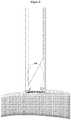
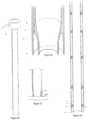
- FIG. 30 to 35describe such an applicator; the extremity (1) is divided into several flexible arms (29) with a final pin (30); the small release (28) in the base of (29) guarantees the flexibility of the spacing and the distal pin (30) is inserted in the opening.
- the actuation processis the sliding of tube (2) into the external tube (1); the arms (29) become deformed elastically and are pushed back radially by tube (2) in order to fasten this applicator to the anatomical structure.
- FIG 32An alternative is presented in Figure 32 , where the elastic arms (31) are stems of cylindrical sections, fixed (1) by any means useful and performed to achieve the same function.
- Figures 33, 34 and 35describe the operational mode.
- FIG. 36 and 37A variant of the previous applicator wherein the elastic strains are replaced with rigid elbows is described in Figure 36 and 37 .
- several bent jaws (32)are fixed to the external tube (1).
- tube (1)pushes back (32) radially toward the outside and is fastening the instrument to the desired organ.
- the geometry of the two tubes (32)induces a closed position and a central nozzle (34) allows the sliding of a wire-guide.
- FIG. 38, 39 and 40A variant of an laparoscopic applicator wherein said applicator is attached to the surface before opening an aperture, is depicted in Figures 38, 39 and 40 ; the external tube (1b) and internal tube (2b) with a rotational move as illustrated in figure 38 ; extremities of the tubes (1b) and (2b) possess a circular network with an equal number of small hooks, respectively (35) and (36) bent one towards the other in such a way that actuation in rotation (2b) relative to (1b) seizes and imprisons the anatomical structure to which the applicator is fastened.
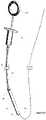
- Figure 41presents an alternative applicator for use as a magnetic anastomosis device such as described in WO2013/009886 A1 using a natural orifice, such as the colon.
- This applicatoris formed by an internal tube (37) and an external tube (38); their bases in the shape of a flange (41) and (42) to allow the sliding of (37) in (38) such as in a syringe and dislodging the anastomosis device; a boring (40) in the interior of (38) retains the anastomosis device in a functional position; the push of (41) towards (42) resulting in the ejection of the anastomosis device and tightening (39) at the end of the internal tube.
- Figure 42presents an endoscopic variant of the applicator, which consists of a hollow cylindrical cartridge (43) with a convex extremity enclosing the device to be released; a flexible and extensible opening (44) is at the extremity of the cartridge (43) which is fixed to the ending (49) of a sheath (46), in this sheath circulates a cable (47) by actuating a push rod (40); the cable (47) slides the piston (48) inside of (43) ejecting the device contained in (43).
Landscapes
- Health & Medical Sciences (AREA)
- Surgery (AREA)
- Life Sciences & Earth Sciences (AREA)
- Medical Informatics (AREA)
- Animal Behavior & Ethology (AREA)
- Engineering & Computer Science (AREA)
- Biomedical Technology (AREA)
- Heart & Thoracic Surgery (AREA)
- Veterinary Medicine (AREA)
- Molecular Biology (AREA)
- Nuclear Medicine, Radiotherapy & Molecular Imaging (AREA)
- General Health & Medical Sciences (AREA)
- Public Health (AREA)
- Pathology (AREA)
- Physiology (AREA)
- Surgical Instruments (AREA)
- Endoscopes (AREA)
Description
- Document
WO 2008/101075 A2 discloses surgical devices for forming an anastomosis between organs and, more particularly, devices that can be inserted through a natural orifice in the body and used to form an anastomosis between various gastrointestinal organs. In an embodiment, the distal end of a hollow outer sleeve is formed with a plurality of tapered segments that each have a substantially pointed distal end. In an unexpanded state, the distal ends converge together to form a pointed distal end, which can flex open to permit other instruments to pass through it. - Document
US2008/0161644 A1 discloses an overtube having a distal end a plurality of needle-like bidirectionally extending projections for mechanically securing it to a wall of an organ of a patient. - Document
US 5,891,159 discloses an introducer tube with an umbrella-like deployment mechanism having a plurality of support members for compressing tissue. - The present invention relates to an applicator for the delivery of injection medical devices by minimally invasive single site surgery (MISS), natural orifice transluminal endoscopic surgery or colonoscopic surgery (NOTES TM).
- The present invention is defined in appended
claim 1. It relates to the embodiment ofFigs. 30 to 35 described here below. Specific embodiments are further defined in the dependent claims. Figure 1 ; illustrates an applicator for a modular magnetic anastomosis device using a laparoscopic technique with tightness valves for maintaining the pneumoperitoneum.Figure 2 ; is a side view of the laparoscopic applicator of the modular magnetic anastomosis device.Figure 3 ; describes a cross longitudinal perspective of the main body of the applicator, with the second beveled and sharpened tube and the arrangement of modular magnetic anastomosis device inside of the second glide tube.Figure 4 ; illustrates the ejection of the anastomosis device with the wire guide from the laparoscopic applicator in the non-deployed configuration.Figure 5 ; describes a variant of the laparoscopic applicator where the main body of the applicator and the internal tube are fitted together with a tightness valve and an external button for opening and closing the applicator.Figure 6 ; shows a cross section of the main body of the applicator fitted with the internal secondary tube with teeth being curved radially and in opposite direction.Figure 7 ; is a presentation of the interaction between the teeth of the main body and the second internal tube of the applicator.Figure 8A-B ; shows separately inner and outer tubes with general orientation of teeth.Figure 9 ; shows the modular magnetic anastomosis device applicator used in endoscopy with the flexible cartridge enclosing the device.Figure 10 ; illustrates the presence of the applicator used in an endoscope.Figure 11 ; shows the plunger pushing and thus ejecting the modular magnetic anastomosis device out of the flexible cartridge of the endoscopic applicator.Figure 12 ; presents the anastomosis device in its deployed configuration using the wire guide to close the device.Figure 13 ; illustrates general structure of a laparoscopic applicator for a modular magnetic anastomosis comprising:- (1) exterior tube
- (2) interior tube
- (3) sealing system
- (4) actuation system
- (5) stowing system
Figure 14 ; is the cross longitudinal perspective of the main body of the applicator.Figure 15 ; illustrates external view of actuation system.Figures 16 ; describes a cross longitudinal view of the actuation system with different components that operate the mechanical movement and rotation of serrated roller.Figure 17 ; illustrates different components that operate the mechanical movement and rotation of the serrated roller.Figure 18 ; illustrates an alternative form of serrated roller.Figures 19 and 20 ; describe a laparoscopic applicator that the stowing system comprises a network of small tooth-needles.Figures 21 and 22 ; illustrate introduction of tooth-needle and deployed form of the tooth-needle after the laparoscopic applicator is fixed to desired anatomic surface.Figures 23, 24 and 25 ; present a laparoscopic applicator where the mechanical movement after stowing the application to desired organ opens and firm a circular network of small grips.Figures 26, 27 and 28 ; describe a laparoscopic applicator which is applied against the surface to be deployed by aspiration.Figure 29 ; illustrates an applicator with exterior and interior tubes in contact with series of rings.Figures 30 and 31 ; illustrate an applicator with an extremity divided in several resilient flexible or non ferromagnetic metal arms with final spur.Figure 32 ; illustrates the applicator that possessing stems of cylindrical sections allowing the fixation of the laparoscopic applicator after entry.Figures 33, 34 and 35 ; illustrate the deployed form of laparoscopic applicator describe infigure 30 and 31 and 32 .Figure 36 and 37 ; illustrate an applicator with rigid articulate hooks.Figures 38, 39 and 40 ; represent laparoscopic applicator that external and interior tubes of the applicator are fitted together with teeth being curved radially and in opposite direction.Figure 41 ; describes a colonoscopy applicator for modular magnetic anastomosis.Figure 42 ; shows a variant of modular magnetic anastomosis device applicator used in endoscopy with the flexible cartridge enclosing the device.- Minimally invasive single site surgery (MISS) or natural orifice transluminal endoscopic surgery (NOTES TM) are terminologies to explain the novel concept of scarless surgery which are increasingly making their way into clinical practice. Laparoscopic and endoscopic surgeries are well-established alternatives to open surgery for anastomosis. In general, the benefits of laparoscopy and endoscopy on postoperative pain, cosmetic benefits, hospital stay and convalescence are widely recognized. Central to the performance of MISS or NOTES surgery is the ability to achieve efficient and effective access to the surgical area of interest via a single port of entry using an endoscopic, percutaneous or laparoscopic applicator.
- The MISS surgery approach has the potential to advance the field of percutaneous intra- and transluminal surgery. By direct percutaneous entry into hollow organs such as the urinary bladder, stomach and colon, newer intra- and transluminal procedures could be developed. The potential advantages of this approach would include operating within a localized pneumoviscerum environment (e.g., pneumovesicum, pneumogastrum or pneumocolum) in contrast to a generalized pneumoperitoneum, thereby potentially allowing certain major abdominal procedures to be performed under regional rather than general anesthesia.
- The development priorities to meet future needs of MISS surgery are evenly divided across four categories: ports, instruments, optics and robotics. Of late, there has been a new entry to MISS surgery platforms: Single-Port Instrument Delivery Extended Research (SPIDER TM developed by TransEnterix Inc., Research Triangle Park, NC, USA). It has been proposed that by instrument manipulation past the level of the skin and fascia, the local wound inflammation would be minimized compared with standard laparoscopy. Surgeons from IRCAD, Strasbourg, performed the first transvaginal NOTES TM cholecystectomy in humans in 2007. Since then, many NOTES TM procedures have been performed for varied indications using one or two instruments for dissection and retraction introduced through the transumbilical rigid trocars. They are primarily labeled as "Hybrid-NOTES." It is a win-win situation for both of these surgical access techniques (MISS and NOTES TM) as they compensate for the disadvantages of each other and still adhere to the concept of "scarless" surgery.
- The use of laparoscopic tools can not only help avoid trauma by decreasing removal and reinsertion but can also reduce the number of incision required to perform a procedure. They also reduce the additional time that is not directly spent in helping the patient in the operating room (OR) and thus reduce the patient risk and costs. Jamshidi et al. demonstrated the safety and efficacy of magnetic compression anastomosis (magnamosis) devices for suturless, fullthickness intestinal anastomosis with serosal apposition and without leaks in a pig model. They further comment that gradient compression is superior to uniform compression. Mechanical integrity of magnetic anastomosis was similar to, if not better than staple or suture counterparts. Endoscopically placed tick internal magnets with external magnetic guidance is a feasible and novel approach to creating gastroenteral anastomosis without abdominal incisions or sutures.
- The IRCAD institute has developed a modular magnetic anastomosis device; the installation of the device requires a limited access compared to its useful surface after deployment. It can be placed accurately and in a minimally invasive fashion in any segment of the digestive tract; it allows realizing bypasses between all hollow viscera; it is also available in all useful sizes by the simple addition of magnetic elements according to the anatomical structure on which it has to be implemented. In its non-deployed shape, the system can be placed inside a small sized channel. It can be placed on a guide-tread and inserted into an access device such as a catheter.
- The present invention relates to an applicator for delivery of injection medical device in a minimally invasive single site surgery (MISS), natural orifice transluminal endoscopic surgery or colonoscopy surgery (NOTES TM).
- The laparoscopic instruments are functioning as a hopper. In contact with the surface to be deployed, the hopper preserves the pressure on the pneumoperitoneum; using standard instruments before or after stowing according to the alternatives aperture is created; and the device is introduced to the internal organ by a flexible or rigid piston according to the alternatives. The upper parts of these laparoscopic instruments are formed in a similar fashion and a set of valves ensures the sealing and the conservation of the pneumoperitoneum; except for the alternatives presented in
figures 26 to 29 , where the fixation is assured using aspiration. The principal structure of the alternatives are two tubes: one internal tube enveloped by an external tube with radial or longitudinal relative movement; wherein the relative movement is ordered by a button, a serrated roller or a handle actuating a radial or longitudinal toothed rack; or simply by manual sliding motion of the two tubes as represented infigures 30 to 35 . The sliding motion of the external and interior tubes actuates various mechanism of fixation located at the end of the device. Figure 1 to Figure 4 present one variant of an applicator for the modular anastomosis device; where the delivery instrument is a laparoscopic applicator with an extremity possessing tightness valves maintaining the pneumoperitoneum for inserting or retrieving the various parts of the anastomosis device or tools for the procedure. The main body of the applicator is an elongated tube; pliers with chuck jaws are placed on either side of the elongated tube, presented inFigure 1 . The extremity of this elongated tube possesses sharp spikes acting as intermediary chuck jaws for the pliers. A second bevelled and sharpened tube is presented inFigs. 1 ,2 and3 ; this second tube glides inside the first one and is used to cut the wall. The modular anastomosis device is logged into the second tube and is ejected to the organ to be deployed using a plunger.Figure 4 illustrates the modular magnetic anastomosis device with the wire guide ejected from the laparoscopic applicator.- In a different variant, the laparoscopic applicator possesses a main body with a second internal tube fitted together.
Figure 5 illustrates this form of the device;Fig. 5 presents the basis with tightness valves allowing to maintain the pneumoperitoneum for insertion or retrieving the various parts of the modular anastomosis device or tools used to carry out the procedure.Figure 6 shows the main body of the applicator, and the internal tube is shown inFigure 6 . Extremities of both of these tubes are teeth being curved radially and in an opposite direction as to grasp the external wall of the digestive tract by simply rotating both tubes represented inFigure 7 . The teeth are maintained in a closed position with a blocking mechanism using springs or tension ribbons resisting to the opening of the applicator jaws shown inFigs. 8A and8B . The open and closed positions of the applicator are manoeuvred by a button or a handle on the external part of the applicator, as illustrated inFig. 5 . - The non-deployed modular magnetic anastomosis device requires limited access compared to its useful surface after deployment, and it can be placed inside a small sized channel and be used by being inserted into an operating channel of the endoscope.
Figure 9 illustrates the various parts of such an applicator, composed of a guide tube 9.1 which is placed inside the operating channel of the endoscope to which is fitted a flexible cartridge 9.4 which encloses the modular magnetic anastomosis device. The device is deployed in the transplant organ by injecting it out from the flexible cartridge via a plunger 9.3 that is moved using a cable 9.2.Figure 10 describes an endoscope 10.1 and the channel 10.2 with the cartridge ejected.Figures 11 and 12 illustrate the ejection of the anastomosis device from the cartridge and the final deployed circular modular magnetic anastomosis device. - A general structure of a laparoscopic applicator is described in
Figure 13 formed by an exterior tube (1), interior tube (2), sealing system (3), actuation system (4), stowing system (5).;Figure 14 is a cross longitudinal view of the applicator. - A structure of one of the actuation systems is described in
Figure 15, 16 and 17 , wherein the different components that operate the actuation system (4) make a translational movement between (1a) and (2a) by the rotation of serrated roller (9). In an alternative structure of the actuation system, presented inFigure 18 , the rotational movement between (1b) and (2b) by the rotation of the serrated roller (9) and a truncated end (8b) on the toothed circular section (10) is illustrated. - One variant of a stowing system (5) is described in
Figures 19 and 20 , where the attachment system is through a network of small tooth-needles (11) fixed in the periphery of opposite sites two by two (14) of the internal tube (2a) a thrust at an right angle (12) slides during the actuation of the serrated roller (9) in small release (13) forming the end (15) of the external tube (1a). The contact of the extremities of the internal tube (14) with the external tube (15); teeth (11) leave their housing (13), take the deployed form presented inFigures 21 and 22 and for two by two the interior loops clutched to the organ to be fastened. - The change in stowing part (5) in another variant is presented in
Figures 23, 24 and 25 , wherein the actuation of the internal tube (2a) compared to the external tube (1a) opens and closes a circular network of small grips. The extremity of the internal tube (2a) possess a regular network of holes by which rivets pass (21); each rivet communicates between the internal tube (2a) and the driveshaft (20). The arm (20) articulates two intermediate arms (19 a) and (19b) on the axis (18d); these two grip (17a) and (17b) are constrained in the axis of rotation (18a), which is interdependent of the external tube (1a); in addition they are connected to the arms (19a) and (19b) by rivets (18b) and (18c); displacement of the internal tube (2a) jointly moves the grips (17 a) and (17b) and actuates the network of claws. - In a variant of a laparoscopic device the attachment to the organ is assured by a mechanism of aspiration under vacuum.
Figures 26, 27, 28, and 29 illustrate such an applicator; the figures describe a unique tubular structure (1d) that replaces the internal and external tubes; a hollow zone (23) linked to a nozzle (22) linked to an external aspiration tube connected to an external device; the extremity of the device (24) under aspiration on a circumferential zone is fixed to the surface to be stowed.Figure 29 shows the variant with external and internal tubes (1c) and (2c) that are maintained in position by a network of rings (25), which are bored with holes (26) allowing the aspiration under vacuum. - In another variant of a laparoscopic applicator the aperture for the surgery is carried out in the anatomical organ before fastening the applicator.
Figures 30 to 35 describe such an applicator; the extremity (1) is divided into several flexible arms (29) with a final pin (30); the small release (28) in the base of (29) guarantees the flexibility of the spacing and the distal pin (30) is inserted in the opening. The actuation process is the sliding of tube (2) into the external tube (1); the arms (29) become deformed elastically and are pushed back radially by tube (2) in order to fasten this applicator to the anatomical structure. An alternative is presented inFigure 32 , where the elastic arms (31) are stems of cylindrical sections, fixed (1) by any means useful and performed to achieve the same function.Figures 33, 34 and 35 describe the operational mode. - A variant of the previous applicator wherein the elastic strains are replaced with rigid elbows is described in
Figure 36 and 37 . In this alternative mode, several bent jaws (32) are fixed to the external tube (1). By a combination of rotation (33) and sliding of the internal tube (2), tube (1) pushes back (32) radially toward the outside and is fastening the instrument to the desired organ. - The geometry of the two tubes (32) induces a closed position and a central nozzle (34) allows the sliding of a wire-guide.
- A variant of an laparoscopic applicator wherein said applicator is attached to the surface before opening an aperture, is depicted in
Figures 38, 39 and 40 ; the external tube (1b) and internal tube (2b) with a rotational move as illustrated infigure 38 ; extremities of the tubes (1b) and (2b) possess a circular network with an equal number of small hooks, respectively (35) and (36) bent one towards the other in such a way that actuation in rotation (2b) relative to (1b) seizes and imprisons the anatomical structure to which the applicator is fastened. Figure 41 presents an alternative applicator for use as a magnetic anastomosis device such as described inWO2013/009886 A1 using a natural orifice, such as the colon. This applicator is formed by an internal tube (37) and an external tube (38); their bases in the shape of a flange (41) and (42) to allow the sliding of (37) in (38) such as in a syringe and dislodging the anastomosis device; a boring (40) in the interior of (38) retains the anastomosis device in a functional position; the push of (41) towards (42) resulting in the ejection of the anastomosis device and tightening (39) at the end of the internal tube.Figure 42 presents an endoscopic variant of the applicator, which consists of a hollow cylindrical cartridge (43) with a convex extremity enclosing the device to be released; a flexible and extensible opening (44) is at the extremity of the cartridge (43) which is fixed to the ending (49) of a sheath (46), in this sheath circulates a cable (47) by actuating a push rod (40); the cable (47) slides the piston (48) inside of (43) ejecting the device contained in (43).
Claims (5)
- An applicator for delivery of an injection medical device through an aperture during minimal invasive surgery, the applicator comprising:a first elongated tube (1) comprising a hollow lumen connecting a proximal end and a distal end, wherein the distal end comprises arms (29) that are elastically deformable and form an elastically deformable pin (30) configuration;a second elongated tube (2) which is enveloped by the first elongated tube (1) and comprises a hollow lumen configured to receive the injection medical device; and wherein the second elongated tube (2) is configured to slide relative to the first elongated tube (1)characterized in that each of the elastically deformable arms (29) of the first elongated tube (1) comprises an outer shoulder on its distal portion and the second elongated tube (2) is positioned so that a sliding of the second elongated tube (2) in the direction of the distal end causes the second elongated tube (2) to push back the elastically deformable arms (29) of the first elongated tube (1) radially thereby deforming the pin (30) configuration so that the elastically deformable arms (29) are pushed back towards an area surrounding the aperture and thereby fastening the applicator to a surgical area of interest at the outer shoulders.
- The applicator of claim 1, wherein the applicator is a laparoscopic instrument.
- The applicator of claim 1, wherein the elastically deformable arms (29) are made of resilient non-ferromagnetic metal.
- The applicator of claim 1, comprising a button, a serrated roller (9), or a handle actuating a radial or longitudinal toothed rack, wherein the second elongated tube (2) is configured and positioned so that it slides relative to the first elongated tube in response to the button, the serrated roller (9), or the handle actuating a radial or longitudinal toothed rack.
- The applicator of claim 1, wherein the elastically deformable arms (29) are fixed to the one end as stems of a cylindrical section.
Priority Applications (1)
| Application Number | Priority Date | Filing Date | Title |
|---|---|---|---|
| EP23157554.9AEP4218616A3 (en) | 2012-12-21 | 2013-12-20 | Applicators for modular magnetic anastomosis device |
Applications Claiming Priority (3)
| Application Number | Priority Date | Filing Date | Title |
|---|---|---|---|
| US201261740865P | 2012-12-21 | 2012-12-21 | |
| US201361794782P | 2013-03-15 | 2013-03-15 | |
| PCT/IB2013/003246WO2014102621A2 (en) | 2012-12-21 | 2013-12-20 | Applicators for modular magnetic anastomosis device |
Related Child Applications (1)
| Application Number | Title | Priority Date | Filing Date |
|---|---|---|---|
| EP23157554.9ADivisionEP4218616A3 (en) | 2012-12-21 | 2013-12-20 | Applicators for modular magnetic anastomosis device |
Publications (2)
| Publication Number | Publication Date |
|---|---|
| EP2934347A2 EP2934347A2 (en) | 2015-10-28 |
| EP2934347B1true EP2934347B1 (en) | 2023-02-22 |
Family
ID=50896332
Family Applications (2)
| Application Number | Title | Priority Date | Filing Date |
|---|---|---|---|
| EP13861506.7AActiveEP2934347B1 (en) | 2012-12-21 | 2013-12-20 | Applicators for modular magnetic anastomosis device |
| EP23157554.9AWithdrawnEP4218616A3 (en) | 2012-12-21 | 2013-12-20 | Applicators for modular magnetic anastomosis device |
Family Applications After (1)
| Application Number | Title | Priority Date | Filing Date |
|---|---|---|---|
| EP23157554.9AWithdrawnEP4218616A3 (en) | 2012-12-21 | 2013-12-20 | Applicators for modular magnetic anastomosis device |
Country Status (4)
| Country | Link |
|---|---|
| US (2) | US10682143B2 (en) |
| EP (2) | EP2934347B1 (en) |
| TW (3) | TWI693059B (en) |
| WO (1) | WO2014102621A2 (en) |
Families Citing this family (29)
| Publication number | Priority date | Publication date | Assignee | Title |
|---|---|---|---|---|
| EP3973892B1 (en) | 2009-07-15 | 2024-10-23 | GT Metabolic Solutions, Inc. | Incisionless gastric bypass devices |
| BR112012016666A2 (en) | 2010-01-05 | 2018-06-05 | Beacon Endoscopic Corp | methods and apparatus for magnetically induced compression anastomosis between adjacent organs. |
| US8870898B2 (en) | 2010-01-05 | 2014-10-28 | GI Windows, Inc. | Self-assembling magnetic anastomosis device having an exoskeleton |
| EP4039200A1 (en) | 2011-07-12 | 2022-08-10 | Ircad | Modular magnetic anastomosis device |
| EP2934347B1 (en) | 2012-12-21 | 2023-02-22 | Ircad | Applicators for modular magnetic anastomosis device |
| US10517600B2 (en) | 2015-03-12 | 2019-12-31 | G.I. Windows, Inc. | Magnetic anastomosis devices with varying magnetic force at a distance |
| JP7082052B2 (en) | 2015-09-03 | 2022-06-07 | ネプチューン メディカル インク. | A device for advancing the endoscope in the small intestine |
| EP3500151A4 (en) | 2016-08-18 | 2020-03-25 | Neptune Medical Inc. | DEVICE AND METHOD FOR IMPROVED VISUALIZATION OF THE SMALL BOWEL |
| FR3055793B1 (en) | 2016-09-09 | 2018-08-31 | Institut Hospitalo-Universitaire De Chirurgie Mini-Invasive Guidee Par L'image | ENDOSCOPIC NEEDLE HOLDER |
| US10206682B2 (en)* | 2017-01-30 | 2019-02-19 | Ethicon Llc | Magnetic tissue compression device with backup mechanical latch |
| JP7379321B2 (en) | 2017-07-20 | 2023-11-14 | ネプチューン メディカル インク. | Dynamically rigid overtube |
| US12059128B2 (en) | 2018-05-31 | 2024-08-13 | Neptune Medical Inc. | Device and method for enhanced visualization of the small intestine |
| ES2971887T3 (en) | 2018-06-02 | 2024-06-10 | Gi Windows Inc | Devices for forming anastomoses |
| CN112714658A (en) | 2018-07-19 | 2021-04-27 | 海王星医疗公司 | Dynamic rigidized composite medical structure |
| WO2020214221A1 (en) | 2019-04-17 | 2020-10-22 | Neptune Medical Inc. | Dynamically rigidizing composite medical structures |
| US11793392B2 (en) | 2019-04-17 | 2023-10-24 | Neptune Medical Inc. | External working channels |
| CA3178444A1 (en) | 2020-03-30 | 2021-10-07 | Neptune Medical Inc. | Layered walls for rigidizing devices |
| US11576676B2 (en) | 2020-09-18 | 2023-02-14 | Gt Metabolic Solutions, Inc. | Anastomosis formation with magnetic devices having temporary retention member |
| WO2022086992A1 (en) | 2020-10-20 | 2022-04-28 | Myka Labs, Inc. | Accelerated patency magnamosis |
| WO2022132351A1 (en) | 2020-12-18 | 2022-06-23 | Gt Metabolic Solutions, Inc. | Devices and methods for assisting magnetic compression anastomosis |
| KR20230133374A (en) | 2021-01-29 | 2023-09-19 | 넵튠 메디컬 인코포레이티드 | Device and method for preventing inadvertent movement of a dynamic stiffening device |
| WO2022225923A1 (en) | 2021-04-20 | 2022-10-27 | G.I. Windows, Inc. | Systems, devices, and methods for endoscope or laparoscopic magnetic navigation |
| US11583280B2 (en) | 2021-04-30 | 2023-02-21 | Gt Metabolic Solutions, Inc. | Anastomosis formation with magnetic devices having bioresorbable retention member |
| USD1081998S1 (en) | 2022-03-17 | 2025-07-01 | Gt Metabolic Solutions, Inc. | Anastomosis formation device |
| KR20250003955A (en) | 2022-04-27 | 2025-01-07 | 넵튠 메디컬 인코포레이티드 | Sanitary outer covering for endoscope |
| US12201300B2 (en) | 2022-08-05 | 2025-01-21 | G.I. Windows, Inc. | Magnetic compression anastomosis device with multipiece vertebra |
| JP2025529235A (en) | 2022-09-01 | 2025-09-04 | ジーアイ ウィンドウズ, インコーポレイテッド | Pressure Profile Magnetic Compression Anastomosis Device |
| JP2025529236A (en) | 2022-09-02 | 2025-09-04 | ジーアイ ウィンドウズ, インコーポレイテッド | Systems, devices and methods for endoscopic or laparoscopic magnetic navigation |
| US12330292B2 (en) | 2023-09-28 | 2025-06-17 | Neptune Medical Inc. | Telescoping robot |
Citations (1)
| Publication number | Priority date | Publication date | Assignee | Title |
|---|---|---|---|---|
| WO2008101075A2 (en)* | 2007-02-15 | 2008-08-21 | Ethicon Endo-Surgery, Inc | Surgical devices and methods for forming an anastomosis between organs by gaining access thereto through a natural orifice in the body |
Family Cites Families (38)
| Publication number | Priority date | Publication date | Assignee | Title |
|---|---|---|---|---|
| CH591237A5 (en) | 1975-11-06 | 1977-09-15 | Bbc Brown Boveri & Cie | |
| SU736966A1 (en) | 1978-10-16 | 1980-05-30 | Предприятие П/Я Р-6927 | Method of treating short esophageal structures |
| US5667488A (en)* | 1992-08-12 | 1997-09-16 | Vidamed, Inc. | Transurethral needle ablation device and method for the treatment of the prostate |
| US6110187A (en) | 1995-02-24 | 2000-08-29 | Heartport, Inc. | Device and method for minimizing heart displacements during a beating heart surgical procedure |
| US5817062A (en)* | 1996-03-12 | 1998-10-06 | Heartport, Inc. | Trocar |
| US5981159A (en)* | 1996-09-27 | 1999-11-09 | Eastman Kodak Company | Photographic material |
| US5891159A (en)* | 1997-05-02 | 1999-04-06 | Cardiothoratic Systems, Inc. | Automatic purse string suture device |
| US6352543B1 (en) | 2000-04-29 | 2002-03-05 | Ventrica, Inc. | Methods for forming anastomoses using magnetic force |
| US6793621B2 (en)* | 2001-03-08 | 2004-09-21 | Atropos Limited | Colonic overtube |
| US7695427B2 (en) | 2002-04-26 | 2010-04-13 | Torax Medical, Inc. | Methods and apparatus for treating body tissue sphincters and the like |
| US6769594B2 (en)* | 2002-05-31 | 2004-08-03 | Tyco Healthcare Group, Lp | End-to-end anastomosis instrument and method for performing same |
| WO2004028585A2 (en) | 2002-09-30 | 2004-04-08 | Sightline Technologies Ltd. | Piston-actuated endoscopic tool |
| WO2004096013A2 (en) | 2003-04-26 | 2004-11-11 | Ventrica, Inc. | Methods and devices for temporarily sealing a blood vessel during an anastomosis |
| CN1297237C (en) | 2004-06-03 | 2007-01-31 | 西安交通大学 | Auxiliary ring for surgical anastomosis |
| US20090078736A1 (en)* | 2004-07-26 | 2009-03-26 | Van Lue Stephen J | Surgical stapler with magnetically secured components |
| US8439915B2 (en) | 2004-09-29 | 2013-05-14 | The Regents Of The University Of California | Apparatus and methods for magnetic alteration of anatomical features |
| US20060106288A1 (en) | 2004-11-17 | 2006-05-18 | Roth Alex T | Remote tissue retraction device |
| JP4681920B2 (en) | 2005-03-30 | 2011-05-11 | オリンパスメディカルシステムズ株式会社 | Indwelling device placed in body cavity |
| AU2006236185B2 (en)* | 2005-04-20 | 2012-03-29 | Cook Medical Technologies Llc | Internal cannulated joint for medical delivery systems |
| JP2009507617A (en)* | 2005-09-14 | 2009-02-26 | ネオガイド システムズ, インコーポレイテッド | Method and apparatus for performing transluminal and other operations |
| US7988656B2 (en) | 2006-01-13 | 2011-08-02 | Olympus Medical Systems Corp. | Natural orifice medical operation and endoscopic overtube |
| US20070167868A1 (en)* | 2006-01-18 | 2007-07-19 | Lsi Solutions, Inc. | Ergonomic needle tissue harvesting instrument not requiring a stylet |
| US20070299310A1 (en)* | 2006-06-21 | 2007-12-27 | Phillips Edward H | Device for shielding the lens of a flexible or rigid surgical endoscope |
| JP5179507B2 (en) | 2006-11-10 | 2013-04-10 | クック メディカル テクノロジーズ エルエルシー | Ring magnet for surgical procedure |
| US20080161644A1 (en) | 2006-12-29 | 2008-07-03 | Ghabrial Ragae M | Method of and apparatus for attaching an instrument to an organ wall |
| WO2009048954A1 (en)* | 2007-10-09 | 2009-04-16 | Wilson-Cook Medical, Inc. | Magnetic anastomosis device having improved delivery |
| WO2009094434A2 (en)* | 2008-01-22 | 2009-07-30 | University Of South Florida | Endoscopic overtube |
| US9566146B2 (en)* | 2008-12-19 | 2017-02-14 | St. Jude Medical, Inc. | Cardiovascular valve and valve housing apparatuses and systems |
| WO2011081988A1 (en) | 2009-12-30 | 2011-07-07 | Wilson-Cook Medical, Inc. | Elongate magnet for a magnetic anastomosis device |
| BR112012016666A2 (en) | 2010-01-05 | 2018-06-05 | Beacon Endoscopic Corp | methods and apparatus for magnetically induced compression anastomosis between adjacent organs. |
| US8870898B2 (en) | 2010-01-05 | 2014-10-28 | GI Windows, Inc. | Self-assembling magnetic anastomosis device having an exoskeleton |
| US8636751B2 (en)* | 2010-05-26 | 2014-01-28 | Ethicon Endo-Surgery, Inc. | Methods and devices for the rerouting of chyme to induce intestinal brake |
| US9332990B2 (en) | 2010-12-30 | 2016-05-10 | Wake Forest University Health Sciences | Ureter to ileal conduit anastomosis using magnetic compression and related delivery devices and methods |
| EP4039200A1 (en) | 2011-07-12 | 2022-08-10 | Ircad | Modular magnetic anastomosis device |
| EP2934347B1 (en) | 2012-12-21 | 2023-02-22 | Ircad | Applicators for modular magnetic anastomosis device |
| EP3488795A1 (en) | 2014-07-23 | 2019-05-29 | GI Windows Inc. | Magnetic anastomosis devices and methods of delivery |
| US10517600B2 (en) | 2015-03-12 | 2019-12-31 | G.I. Windows, Inc. | Magnetic anastomosis devices with varying magnetic force at a distance |
| WO2018057613A2 (en) | 2016-09-20 | 2018-03-29 | Neurotronic, Inc. | Magnetic anastomosis devices |
- 2013
- 2013-12-20EPEP13861506.7Apatent/EP2934347B1/enactiveActive
- 2013-12-20TWTW106142659Apatent/TWI693059B/enactive
- 2013-12-20EPEP23157554.9Apatent/EP4218616A3/ennot_activeWithdrawn
- 2013-12-20TWTW105126839Apatent/TWI615125B/enactive
- 2013-12-20TWTW102147684Apatent/TWI559887B/enactive
- 2013-12-20USUS14/654,643patent/US10682143B2/enactiveActive
- 2013-12-20WOPCT/IB2013/003246patent/WO2014102621A2/enactiveApplication Filing
- 2020
- 2020-04-28USUS16/861,050patent/US12161339B2/enactiveActive
Patent Citations (1)
| Publication number | Priority date | Publication date | Assignee | Title |
|---|---|---|---|---|
| WO2008101075A2 (en)* | 2007-02-15 | 2008-08-21 | Ethicon Endo-Surgery, Inc | Surgical devices and methods for forming an anastomosis between organs by gaining access thereto through a natural orifice in the body |
Also Published As
| Publication number | Publication date |
|---|---|
| TW201709868A (en) | 2017-03-16 |
| EP4218616A2 (en) | 2023-08-02 |
| WO2014102621A2 (en) | 2014-07-03 |
| TWI559887B (en) | 2016-12-01 |
| WO2014102621A3 (en) | 2015-04-23 |
| TW201440717A (en) | 2014-11-01 |
| US20210007744A1 (en) | 2021-01-14 |
| EP2934347A2 (en) | 2015-10-28 |
| US20150342608A1 (en) | 2015-12-03 |
| US12161339B2 (en) | 2024-12-10 |
| US10682143B2 (en) | 2020-06-16 |
| TWI615125B (en) | 2018-02-21 |
| TW201811274A (en) | 2018-04-01 |
| TWI693059B (en) | 2020-05-11 |
| EP4218616A3 (en) | 2023-08-30 |
Similar Documents
| Publication | Publication Date | Title |
|---|---|---|
| US12161339B2 (en) | Applicators for modular magnetic anastomosis device | |
| US10595856B2 (en) | Stitching device with long needle delivery | |
| US20210330320A1 (en) | Endoscopic suturing system having external instrument channel | |
| US9308011B2 (en) | Surgical device and methods | |
| US20200289111A1 (en) | Stitching device with long needle | |
| US20190053805A1 (en) | Tissue apposition clip application methods | |
| EP2073721B1 (en) | A clip device and system for assisting surgical procedures | |
| US20070049966A1 (en) | Surgical instrument | |
| US8496633B2 (en) | Surgical access device with adjustable cannula | |
| US20140222020A1 (en) | Telescoping reinforcements for instrument channel shafts | |
| CN109009255A (en) | Slide suture grasper | |
| WO1996039946A1 (en) | Wound closure device | |
| US8496632B2 (en) | Surgical access device with adjustable cannula | |
| US8491545B2 (en) | Surgical access device with adjustable cannula | |
| US8403837B2 (en) | Deployable jaws retraction device | |
| US20140316440A1 (en) | Multiple clip endoscopic tissue clipping system and device | |
| US8439881B2 (en) | Surgical access device with adjustable cannula | |
| US20210059659A1 (en) | Devices and methods for closure of openings in tissue |
Legal Events
| Date | Code | Title | Description |
|---|---|---|---|
| PUAI | Public reference made under article 153(3) epc to a published international application that has entered the european phase | Free format text:ORIGINAL CODE: 0009012 | |
| AK | Designated contracting states | Kind code of ref document:A2 Designated state(s):AL AT BE BG CH CY CZ DE DK EE ES FI FR GB GR HR HU IE IS IT LI LT LU LV MC MK MT NL NO PL PT RO RS SE SI SK SM TR | |
| AX | Request for extension of the european patent | Extension state:BA ME | |
| 17P | Request for examination filed | Effective date:20151023 | |
| RBV | Designated contracting states (corrected) | Designated state(s):AL AT BE BG CH CY CZ DE DK EE ES FI FR GB GR HR HU IE IS IT LI LT LU LV MC MK MT NL NO PL PT RO RS SE SI SK SM TR | |
| DAX | Request for extension of the european patent (deleted) | ||
| STAA | Information on the status of an ep patent application or granted ep patent | Free format text:STATUS: EXAMINATION IS IN PROGRESS | |
| 17Q | First examination report despatched | Effective date:20170830 | |
| GRAP | Despatch of communication of intention to grant a patent | Free format text:ORIGINAL CODE: EPIDOSNIGR1 | |
| STAA | Information on the status of an ep patent application or granted ep patent | Free format text:STATUS: GRANT OF PATENT IS INTENDED | |
| RIC1 | Information provided on ipc code assigned before grant | Ipc:A61B 17/34 20060101ALI20220630BHEP Ipc:A61B 17/11 20060101AFI20220630BHEP | |
| INTG | Intention to grant announced | Effective date:20220715 | |
| RIN1 | Information on inventor provided before grant (corrected) | Inventor name:DIANA, MICHELE Inventor name:HERNANDEZ, JUAN | |
| GRAJ | Information related to disapproval of communication of intention to grant by the applicant or resumption of examination proceedings by the epo deleted | Free format text:ORIGINAL CODE: EPIDOSDIGR1 | |
| STAA | Information on the status of an ep patent application or granted ep patent | Free format text:STATUS: EXAMINATION IS IN PROGRESS | |
| GRAS | Grant fee paid | Free format text:ORIGINAL CODE: EPIDOSNIGR3 | |
| STAA | Information on the status of an ep patent application or granted ep patent | Free format text:STATUS: GRANT OF PATENT IS INTENDED | |
| GRAP | Despatch of communication of intention to grant a patent | Free format text:ORIGINAL CODE: EPIDOSNIGR1 | |
| INTC | Intention to grant announced (deleted) | ||
| RIN1 | Information on inventor provided before grant (corrected) | Inventor name:DIANA, MICHELE Inventor name:HERNANDEZ, JUAN | |
| INTG | Intention to grant announced | Effective date:20221208 | |
| GRAA | (expected) grant | Free format text:ORIGINAL CODE: 0009210 | |
| STAA | Information on the status of an ep patent application or granted ep patent | Free format text:STATUS: THE PATENT HAS BEEN GRANTED | |
| AK | Designated contracting states | Kind code of ref document:B1 Designated state(s):AL AT BE BG CH CY CZ DE DK EE ES FI FR GB GR HR HU IE IS IT LI LT LU LV MC MK MT NL NO PL PT RO RS SE SI SK SM TR | |
| REG | Reference to a national code | Ref country code:GB Ref legal event code:FG4D | |
| REG | Reference to a national code | Ref country code:CH Ref legal event code:EP | |
| REG | Reference to a national code | Ref country code:AT Ref legal event code:REF Ref document number:1549016 Country of ref document:AT Kind code of ref document:T Effective date:20230315 Ref country code:IE Ref legal event code:FG4D | |
| REG | Reference to a national code | Ref country code:DE Ref legal event code:R096 Ref document number:602013083359 Country of ref document:DE | |
| REG | Reference to a national code | Ref country code:LT Ref legal event code:MG9D | |
| REG | Reference to a national code | Ref country code:NL Ref legal event code:MP Effective date:20230222 | |
| P01 | Opt-out of the competence of the unified patent court (upc) registered | Effective date:20230530 | |
| REG | Reference to a national code | Ref country code:AT Ref legal event code:MK05 Ref document number:1549016 Country of ref document:AT Kind code of ref document:T Effective date:20230222 | |
| PG25 | Lapsed in a contracting state [announced via postgrant information from national office to epo] | Ref country code:RS Free format text:LAPSE BECAUSE OF FAILURE TO SUBMIT A TRANSLATION OF THE DESCRIPTION OR TO PAY THE FEE WITHIN THE PRESCRIBED TIME-LIMIT Effective date:20230222 Ref country code:PT Free format text:LAPSE BECAUSE OF FAILURE TO SUBMIT A TRANSLATION OF THE DESCRIPTION OR TO PAY THE FEE WITHIN THE PRESCRIBED TIME-LIMIT Effective date:20230622 Ref country code:NO Free format text:LAPSE BECAUSE OF FAILURE TO SUBMIT A TRANSLATION OF THE DESCRIPTION OR TO PAY THE FEE WITHIN THE PRESCRIBED TIME-LIMIT Effective date:20230522 Ref country code:NL Free format text:LAPSE BECAUSE OF FAILURE TO SUBMIT A TRANSLATION OF THE DESCRIPTION OR TO PAY THE FEE WITHIN THE PRESCRIBED TIME-LIMIT Effective date:20230222 Ref country code:LV Free format text:LAPSE BECAUSE OF FAILURE TO SUBMIT A TRANSLATION OF THE DESCRIPTION OR TO PAY THE FEE WITHIN THE PRESCRIBED TIME-LIMIT Effective date:20230222 Ref country code:LT Free format text:LAPSE BECAUSE OF FAILURE TO SUBMIT A TRANSLATION OF THE DESCRIPTION OR TO PAY THE FEE WITHIN THE PRESCRIBED TIME-LIMIT Effective date:20230222 Ref country code:HR Free format text:LAPSE BECAUSE OF FAILURE TO SUBMIT A TRANSLATION OF THE DESCRIPTION OR TO PAY THE FEE WITHIN THE PRESCRIBED TIME-LIMIT Effective date:20230222 Ref country code:ES Free format text:LAPSE BECAUSE OF FAILURE TO SUBMIT A TRANSLATION OF THE DESCRIPTION OR TO PAY THE FEE WITHIN THE PRESCRIBED TIME-LIMIT Effective date:20230222 Ref country code:AT Free format text:LAPSE BECAUSE OF FAILURE TO SUBMIT A TRANSLATION OF THE DESCRIPTION OR TO PAY THE FEE WITHIN THE PRESCRIBED TIME-LIMIT Effective date:20230222 | |
| PG25 | Lapsed in a contracting state [announced via postgrant information from national office to epo] | Ref country code:SE Free format text:LAPSE BECAUSE OF FAILURE TO SUBMIT A TRANSLATION OF THE DESCRIPTION OR TO PAY THE FEE WITHIN THE PRESCRIBED TIME-LIMIT Effective date:20230222 Ref country code:PL Free format text:LAPSE BECAUSE OF FAILURE TO SUBMIT A TRANSLATION OF THE DESCRIPTION OR TO PAY THE FEE WITHIN THE PRESCRIBED TIME-LIMIT Effective date:20230222 Ref country code:IS Free format text:LAPSE BECAUSE OF FAILURE TO SUBMIT A TRANSLATION OF THE DESCRIPTION OR TO PAY THE FEE WITHIN THE PRESCRIBED TIME-LIMIT Effective date:20230622 Ref country code:GR Free format text:LAPSE BECAUSE OF FAILURE TO SUBMIT A TRANSLATION OF THE DESCRIPTION OR TO PAY THE FEE WITHIN THE PRESCRIBED TIME-LIMIT Effective date:20230523 Ref country code:FI Free format text:LAPSE BECAUSE OF FAILURE TO SUBMIT A TRANSLATION OF THE DESCRIPTION OR TO PAY THE FEE WITHIN THE PRESCRIBED TIME-LIMIT Effective date:20230222 | |
| PG25 | Lapsed in a contracting state [announced via postgrant information from national office to epo] | Ref country code:SM Free format text:LAPSE BECAUSE OF FAILURE TO SUBMIT A TRANSLATION OF THE DESCRIPTION OR TO PAY THE FEE WITHIN THE PRESCRIBED TIME-LIMIT Effective date:20230222 Ref country code:RO Free format text:LAPSE BECAUSE OF FAILURE TO SUBMIT A TRANSLATION OF THE DESCRIPTION OR TO PAY THE FEE WITHIN THE PRESCRIBED TIME-LIMIT Effective date:20230222 Ref country code:EE Free format text:LAPSE BECAUSE OF FAILURE TO SUBMIT A TRANSLATION OF THE DESCRIPTION OR TO PAY THE FEE WITHIN THE PRESCRIBED TIME-LIMIT Effective date:20230222 Ref country code:DK Free format text:LAPSE BECAUSE OF FAILURE TO SUBMIT A TRANSLATION OF THE DESCRIPTION OR TO PAY THE FEE WITHIN THE PRESCRIBED TIME-LIMIT Effective date:20230222 Ref country code:CZ Free format text:LAPSE BECAUSE OF FAILURE TO SUBMIT A TRANSLATION OF THE DESCRIPTION OR TO PAY THE FEE WITHIN THE PRESCRIBED TIME-LIMIT Effective date:20230222 | |
| REG | Reference to a national code | Ref country code:DE Ref legal event code:R097 Ref document number:602013083359 Country of ref document:DE | |
| PG25 | Lapsed in a contracting state [announced via postgrant information from national office to epo] | Ref country code:SK Free format text:LAPSE BECAUSE OF FAILURE TO SUBMIT A TRANSLATION OF THE DESCRIPTION OR TO PAY THE FEE WITHIN THE PRESCRIBED TIME-LIMIT Effective date:20230222 | |
| PLBE | No opposition filed within time limit | Free format text:ORIGINAL CODE: 0009261 | |
| STAA | Information on the status of an ep patent application or granted ep patent | Free format text:STATUS: NO OPPOSITION FILED WITHIN TIME LIMIT | |
| 26N | No opposition filed | Effective date:20231123 | |
| PG25 | Lapsed in a contracting state [announced via postgrant information from national office to epo] | Ref country code:SI Free format text:LAPSE BECAUSE OF FAILURE TO SUBMIT A TRANSLATION OF THE DESCRIPTION OR TO PAY THE FEE WITHIN THE PRESCRIBED TIME-LIMIT Effective date:20230222 | |
| REG | Reference to a national code | Ref country code:CH Ref legal event code:PL | |
| PG25 | Lapsed in a contracting state [announced via postgrant information from national office to epo] | Ref country code:LU Free format text:LAPSE BECAUSE OF NON-PAYMENT OF DUE FEES Effective date:20231220 | |
| PG25 | Lapsed in a contracting state [announced via postgrant information from national office to epo] | Ref country code:MC Free format text:LAPSE BECAUSE OF FAILURE TO SUBMIT A TRANSLATION OF THE DESCRIPTION OR TO PAY THE FEE WITHIN THE PRESCRIBED TIME-LIMIT Effective date:20230222 | |
| REG | Reference to a national code | Ref country code:BE Ref legal event code:MM Effective date:20231231 | |
| PG25 | Lapsed in a contracting state [announced via postgrant information from national office to epo] | Ref country code:MC Free format text:LAPSE BECAUSE OF FAILURE TO SUBMIT A TRANSLATION OF THE DESCRIPTION OR TO PAY THE FEE WITHIN THE PRESCRIBED TIME-LIMIT Effective date:20230222 Ref country code:LU Free format text:LAPSE BECAUSE OF NON-PAYMENT OF DUE FEES Effective date:20231220 | |
| PG25 | Lapsed in a contracting state [announced via postgrant information from national office to epo] | Ref country code:BE Free format text:LAPSE BECAUSE OF NON-PAYMENT OF DUE FEES Effective date:20231231 | |
| PG25 | Lapsed in a contracting state [announced via postgrant information from national office to epo] | Ref country code:CH Free format text:LAPSE BECAUSE OF NON-PAYMENT OF DUE FEES Effective date:20231231 | |
| PG25 | Lapsed in a contracting state [announced via postgrant information from national office to epo] | Ref country code:CH Free format text:LAPSE BECAUSE OF NON-PAYMENT OF DUE FEES Effective date:20231231 Ref country code:BE Free format text:LAPSE BECAUSE OF NON-PAYMENT OF DUE FEES Effective date:20231231 | |
| PG25 | Lapsed in a contracting state [announced via postgrant information from national office to epo] | Ref country code:BG Free format text:LAPSE BECAUSE OF FAILURE TO SUBMIT A TRANSLATION OF THE DESCRIPTION OR TO PAY THE FEE WITHIN THE PRESCRIBED TIME-LIMIT Effective date:20230222 | |
| PG25 | Lapsed in a contracting state [announced via postgrant information from national office to epo] | Ref country code:BG Free format text:LAPSE BECAUSE OF FAILURE TO SUBMIT A TRANSLATION OF THE DESCRIPTION OR TO PAY THE FEE WITHIN THE PRESCRIBED TIME-LIMIT Effective date:20230222 | |
| PGFP | Annual fee paid to national office [announced via postgrant information from national office to epo] | Ref country code:GB Payment date:20241227 Year of fee payment:12 | |
| PGFP | Annual fee paid to national office [announced via postgrant information from national office to epo] | Ref country code:FR Payment date:20241226 Year of fee payment:12 | |
| PGFP | Annual fee paid to national office [announced via postgrant information from national office to epo] | Ref country code:IE Payment date:20241227 Year of fee payment:12 | |
| PGFP | Annual fee paid to national office [announced via postgrant information from national office to epo] | Ref country code:IT Payment date:20241218 Year of fee payment:12 | |
| PGFP | Annual fee paid to national office [announced via postgrant information from national office to epo] | Ref country code:DE Payment date:20241227 Year of fee payment:12 | |
| PG25 | Lapsed in a contracting state [announced via postgrant information from national office to epo] | Ref country code:CY Free format text:LAPSE BECAUSE OF FAILURE TO SUBMIT A TRANSLATION OF THE DESCRIPTION OR TO PAY THE FEE WITHIN THE PRESCRIBED TIME-LIMIT; INVALID AB INITIO Effective date:20131220 | |
| PG25 | Lapsed in a contracting state [announced via postgrant information from national office to epo] | Ref country code:HU Free format text:LAPSE BECAUSE OF FAILURE TO SUBMIT A TRANSLATION OF THE DESCRIPTION OR TO PAY THE FEE WITHIN THE PRESCRIBED TIME-LIMIT; INVALID AB INITIO Effective date:20131220 |