EP2933566B1 - Oven and method for controlling the same - Google Patents
Oven and method for controlling the sameDownload PDFInfo
- Publication number
- EP2933566B1 EP2933566B1EP15163408.6AEP15163408AEP2933566B1EP 2933566 B1EP2933566 B1EP 2933566B1EP 15163408 AEP15163408 AEP 15163408AEP 2933566 B1EP2933566 B1EP 2933566B1
- Authority
- EP
- European Patent Office
- Prior art keywords
- temperature
- heater
- time
- period
- control unit
- Prior art date
- Legal status (The legal status is an assumption and is not a legal conclusion. Google has not performed a legal analysis and makes no representation as to the accuracy of the status listed.)
- Active
Links
Images


Classifications
- F—MECHANICAL ENGINEERING; LIGHTING; HEATING; WEAPONS; BLASTING
- F24—HEATING; RANGES; VENTILATING
- F24C—DOMESTIC STOVES OR RANGES ; DETAILS OF DOMESTIC STOVES OR RANGES, OF GENERAL APPLICATION
- F24C7/00—Stoves or ranges heated by electric energy
- F24C7/08—Arrangement or mounting of control or safety devices
- F24C7/087—Arrangement or mounting of control or safety devices of electric circuits regulating heat
- F—MECHANICAL ENGINEERING; LIGHTING; HEATING; WEAPONS; BLASTING
- F24—HEATING; RANGES; VENTILATING
- F24C—DOMESTIC STOVES OR RANGES ; DETAILS OF DOMESTIC STOVES OR RANGES, OF GENERAL APPLICATION
- F24C7/00—Stoves or ranges heated by electric energy
- F24C7/08—Arrangement or mounting of control or safety devices
- F24C7/082—Arrangement or mounting of control or safety devices on ranges, e.g. control panels, illumination
- F24C7/085—Arrangement or mounting of control or safety devices on ranges, e.g. control panels, illumination on baking ovens
- A—HUMAN NECESSITIES
- A23—FOODS OR FOODSTUFFS; TREATMENT THEREOF, NOT COVERED BY OTHER CLASSES
- A23L—FOODS, FOODSTUFFS OR NON-ALCOHOLIC BEVERAGES, NOT OTHERWISE PROVIDED FOR; PREPARATION OR TREATMENT THEREOF
- A23L5/00—Preparation or treatment of foods or foodstuffs, in general; Food or foodstuffs obtained thereby; Materials therefor
- A23L5/10—General methods of cooking foods, e.g. by roasting or frying
- F—MECHANICAL ENGINEERING; LIGHTING; HEATING; WEAPONS; BLASTING
- F24—HEATING; RANGES; VENTILATING
- F24C—DOMESTIC STOVES OR RANGES ; DETAILS OF DOMESTIC STOVES OR RANGES, OF GENERAL APPLICATION
- F24C7/00—Stoves or ranges heated by electric energy
- F24C7/08—Arrangement or mounting of control or safety devices
- F24C7/081—Arrangement or mounting of control or safety devices on stoves
- A—HUMAN NECESSITIES
- A23—FOODS OR FOODSTUFFS; TREATMENT THEREOF, NOT COVERED BY OTHER CLASSES
- A23V—INDEXING SCHEME RELATING TO FOODS, FOODSTUFFS OR NON-ALCOHOLIC BEVERAGES AND LACTIC OR PROPIONIC ACID BACTERIA USED IN FOODSTUFFS OR FOOD PREPARATION
- A23V2002/00—Food compositions, function of food ingredients or processes for food or foodstuffs
Definitions
- the present inventionrelates to an oven that controls on/off operation of a heater and a method of controlling the same.
- Ovenswhich are one form of cooking appliance, cook foods by heat. Such ovens are divided into a gas oven and an electric oven according to heat source.
- a gas ovenuses gas as a heat source and heats and cooks food using flames ignited by a plurality of burners
- an electric ovenuses electricity as a heat source and heats and cooks food using heat emitted from a heater. That is, electric ovens use electricity as a heat source and cook food using radiant heat, convection heat, and conduction heat.
- Such electric ovenssimultaneously heat an outside and an inside of food to be cooked and thus exhibit a faster cooking speed, higher thermal efficiency, and stability than gas ovens and, accordingly, use thereof is increasing.
- an electric ovenin general, includes a main body that defines an exterior appearance of the oven and has an open front surface through which food to be cooked is introduced into a cooking compartment defined in the main body and a door installed at a front side of the main body so as to selectively open or close the cooking compartment.
- the door of the electric ovenconsists of plural pieces of glass to prevent heat in the cooking compartment from being emitted outside and some of the pieces of glass have a heat-reflective coating surface.
- US2003/218002 , US2007/084849 , AU 2004 255 018 , and EP 0 275 990relate to controlling power to heating elements in ovens in order to maintain a steady state temperature.
- US 2013/269539 A1relates to a variable temperature cooking method that uses a predetermined variable temperature reference profile.
- an oven according to claim 1there is provided an oven according to claim 1.
- Optional featuresare set out in the dependent claims.
- an ovenincludes at least one heater arranged in a cooking compartment, a temperature sensor to sense a temperature of the cooking compartment every preset period of time, and a control unit to reset on/off times for each period of the heater based on a preset target temperature and a current temperature and previous temperature of the cooking compartment sensed by the temperature sensor and to control the heater to be driven according to the reset on/off times.
- the control unitmay control driving of the heater such that the heater is turned on until prior to a preheating completion time and may reset on/off times for a period after the preheating completion time of the heater.
- the current temperaturemay be a temperature of the cooking compartment at a time at which the corresponding period starts.
- the previous temperaturemay be a temperature of the cooking compartment at a time at which a previous period starts.
- the ovenmay further include a storage unit to store on/off times of the heater preset according to temperature differences.
- the control unitmay extract the on/off times of the heater stored in the storage unit, based on a difference between the target temperature and a temperature of the cooking compartment at a preheating completion time.
- the control unitmay calculate on/off increase or decrease times of the heater based on the target temperature, the current temperature, and the previous temperature.
- the control unitmay calculate first on/off increase or decrease times of the heater by comparing the target temperature and the current temperature.
- the control unitmay calculate the first on/off increase or decrease times so that, for a period at which the current temperature exceeds the target temperature, the on time of the heater decreases and the off time of the heater increases.
- the control unitmay calculate the first on/off increase or decrease times so that, for a period at which the current temperature is lower than the target temperature, the on time of the heater increases and the off time of the heater decreases.
- the control unitmay calculate second on/off increase or decrease times of the heater by comparing the current temperature and the previous temperature.
- the control unitmay calculate the second on/off increase or decrease times for a period at which the current temperature and the previous temperature are identical, through comparison between the target temperature and the current temperature.
- the control unitmay calculate the second on/off increase or decrease times so that, for a period at which the current temperature exceeds the previous temperature, the on time of the heater decreases and the off time of the heater increases.
- the control unitmay calculate the second on/off increase or decrease time so that, for a period at which the current temperature is lower than the previous temperature, the on time of the heater increases and the off time of the heater decreases.
- the control unitmay reset on/off times of the heater by accumulating the calculated on/off increase or decrease times of the heater to the extracted on/off times.
- the control unitmay adjust an interval or frequency of the period.
- an ovenincludes at least one heater installed inside a cooking compartment, a temperature sensor to sense a temperature of the cooking compartment, an input unit through which a target temperature of the cooking compartment is input by a user, and a control unit to control the heater to be turned on until the temperature of the cooking compartment reaches a preheating temperature and to control the heater to be turned on/off based on the target temperature and the temperature of the cooking compartment after the temperature of the cooking compartment reaches the preheating temperature, when the target temperature is input.
- the control unitmay control on/off of the heater so that the temperature of the cooking compartment is converged to the target temperature.
- the control unitmay periodically set on/off times of the heater and control driving of the heater according to the set on/off times.
- a method of controlling an ovenincludes sensing a temperature of a cooking compartment every preset period of time, the sensing being performed by a temperature sensor, resetting on/off times for each period of a heater based on a preset target temperature and a current temperature and previous temperature of the cooking compartment sensed by the temperature sensor, and controlling driving of the heater according to the reset on/off times.
- the resettingmay include controlling the heater to be turned on until prior to a preheating completion time and resetting on/off times for a period after the preheating completion time of the heater.
- the methodmay further include storing on/off times of the heater preset according to temperature differences.
- the methodmay further include extracting the on/off times of the heater stored in the storage unit based on a difference between the target temperature and a temperature of the cooking compartment at a preheating completion time.
- the resettingmay include calculating on/off increase or decrease times of the heater based on the target temperature, the current temperature, and the previous temperature.
- the resettingmay include calculating first on/off increase or decrease times of the heater by comparing the target temperature and the current temperature.
- the calculating of the first on/off increase or decrease timesmay include calculating first on/off increase or decrease times so that, for a period at which the current temperature exceeds the target temperature, the on time of the heater decreases and the off time of the heater increases.
- the calculating of the first on/off increase or decrease timesmay include calculating first on/off increase or decrease times so that, for a period at which the current temperature is lower than the target temperature, the on time of the heater increases.
- the resettingmay include calculating second on/off increase or decrease times of the heater by comparing the current temperature and the previous temperature.
- the calculating of the second on/off increase or decrease timesmay include calculating second on/off increase or decrease times for a period at which the current temperature is identical to the previous temperature, through comparison between the target temperature and the current temperature.
- the calculating of the second on/off increase or decrease timesmay include calculating second on/off increase or decrease times so that, for a period at which the current temperature is higher than the previous temperature, the on time of the heater decreases and the off time of the heater increases.
- the calculating of the second on/off increase or decrease timesmay include calculating second on/off increase or decrease times so that, for a period at which the current temperature is lower than the previous temperature, the on time of the heater increases and the off time of the heater decreases.
- the resettingmay include resetting on/off times of the heater by accumulating the calculated on/off increase or decrease times of the heater to the extracted on/off times.
- the methodmay further include adjusting an interval or frequency of the period.
- FIGS. 1 and 2are perspective views of an oven 1 according to an embodiment of the present disclosure.
- FIG. 1is a perspective view illustrating a state in which a door of the oven 1 is closed.
- FIG. 2is a perspective view illustrating a state in which the door of the oven 1 is open.
- the oven 1includes a main body 10, a cooking compartment 20 arranged in the main body 10, and a heating device to heat the cooking compartment 20.
- the main body 10may be provided at an upper portion thereof with an input unit 12 through which various commands for cooking are input by a user and a display unit 11 to display various cooking information to the user.
- a usermay input commands for starting/ending cooking, selection of cooking menus, cooking time, temperature setting, and the like via the input unit 12 and may check current time, menu selection screen, operating conditions, cooking progress/remaining time, current temperature, setting temperature, and the like via the display unit 11.
- the input unit 12may take the form of buttons or rotatable knobs or may be a software form such as a touch screen.
- the display unit 11may be a liquid crystal display (LCD), an organic light emitting diode (OLED), or the like, but embodiments of the present disclosure are not limited thereto.
- the input unit 12 and the display unit 11are arranged at an upper rear end of the main body 10.
- the input unit 12 and the display unit 11may be arranged at an upper front end of the main body 10 or at other portions thereof. That is, the positions of the input unit 12 and the display unit 11 are not limited.
- the main body 10may include the cooking compartment 20, which is a space where foods are cooked, and a storage cabinet 14 disposed below the cooking compartment 20 and storing various cooking utensils.
- the storage cabinet 14may be configured to be inserted and withdrawn along guide rails (not shown), guide grooves (not shown), or the like using a handle 15 installed at a front surface of the storage cabinet 14 and rollers (not shown) installed at opposite ends thereof.
- the cooking compartment 20may have a hexahedral shape with an open surface.
- the cooking compartment 20has an upper surface 21, a lower surface 22, a rear surface 23, a left-side surface 24, and a right-side surface 25 and a front surface of the cooking compartment 20 may be opened and closed by a door 90.
- the door 90includes hinge elements 30 to be rotatable upward and downward, and a user may open and close the cooking compartment 20 by rotating the door 90 while grasping the handle 92 installed at an upper end of the door 90. Installation positions of the hinge elements 30 and the handle 15 may be different from what is illustrated in FIG. 2 and a rotation direction of the door 90 may vary according to the installation positions.
- the cooking compartment 20when the cooking compartment 20 is opened, foods may be placed in or taken out of the cooking compartment 20. When the cooking compartment 20 is closed, foods may be cooked by heating the cooking compartment 20 according to set values. To check whether food is inside the cooking compartment 20, cooking states of foods, and the like, the door 90 may be provided with a transparent window 91 such that the inside of the cooking compartment 20 is visible from outside.
- the upper surface 21, the lower surface 22, the rear surface 23, the left-side surface 24, and the right-side surface 25 of the cooking compartment 20may be formed of a heat insulating material or may be provided at respective outer sides thereof with heat insulating materials.
- the transparent window 91may be formed of a heat insulating material and the door 90 may be completely or partially formed of a heat insulating material.
- the cooking compartment 20is provided with a grill shelf 50 having a lattice shape and detachably arranged to hold food to be cooked and is provided at opposite side surfaces 24 and 25 thereof with support bodies 40 to support opposite ends of the grill shelf 50.
- the grill shelf 50may include a plurality of grill shelves 50.
- the support bodies 40may include at least a pair of support bodies 40, in particular pairs of support bodies 40 having various heights so as to variously adjust installation height of the grill shelf 50.
- the cooking compartment 20is provided inside thereof with a heating device to cook foods, and the heating device may include a heater module 60 to perform cooking by directly applying radiation to food and a convection module 70 to perform cooking by circulating heated air.
- the heating devicemay include a heater module 60 to perform cooking by directly applying radiation to food and a convection module 70 to perform cooking by circulating heated air.
- the heater module 60may include an upper heater 61 arranged at the upper surface 21 of the cooking compartment 20 and a lower heater 62 arranged at the lower surface 22 of the cooking compartment 20.
- the convection module 70may include two convection fans 71 and 72 arranged at the rear surface 23 of the cooking compartment 20. The number of heaters constituting the heater module 60 or the number of convection fans constituting the convection module 70 is not limited to the embodiment illustrated in FIG. 2 .
- the heater module 60may further include a rear heater (not shown) coupled to the convection fans 71 and 72, and the convection module 70 may include a single convection fan.
- a rear heater(not shown) coupled to the convection fans 71 and 72
- the convection module 70may include a single convection fan.
- the heater module 60allows direct heating of food inside the cooking compartment 20 through radiation.
- the upper heater 61is arranged at the upper surface 21 of the cooking compartment 20 to be exposed and thus may heat an upper side of the food.
- the lower heater 62is arranged in an unexposed state at the lower surface 22 of the cooking compartment 20 so as to be protected from food, oil generated therefrom, or the like, to heat a lower side of the food.
- the convection module 70shortens cooking time of food by circulating air heated by the heater module 60.
- heated airis circulated inside the cooking compartment 20 as the convection fans 71 and 72 rotate, and circulated heat is added to the radiation of the heater module 60 and thus increases cooking speed of the food.
- the convection module 70may further include a convection fan accommodation unit (not shown) to accommodate the convection fans 71 and 72 and partition plates 75 to separate the cooking compartment 20 from the convection fans 71 and 72 or to separate the cooking compartment 20 from the convection fan accommodation unit.
- the partition plates 75may be provided with a plurality of holes to suction air of the cooking compartment 20 into the convection fan accommodation unit and to discharge air circulated by the convection fans 71 and 72 to the cooking compartment 20.
- a general modefood is cooked by driving only the heater module 60.
- the convection module 70is driven together with the heater module 60. That is, the oven 1 cooks food using radiation generated by the heater module 60 and in the convection mode, cooking of the food is assisted by rotation of the convection fans 71 and 72.
- the heater module 60is basically driven to cook food, and the heater module 60 repeats on and off states so that food is cooked at a set temperature.
- a "temperature ripple phenomenon" in which internal temperature of the cooking compartment 20 fluctuates in a predetermined rangeoccurs. Conversion of the heater module 60 to the on state or off state does not immediately affect the internal temperature of the cooking compartment 20 and requires a certain period of time to affect the inside of the cooking compartment 20. Thus, when on/off of the heater module 60 is simply controlled at a point at which a temperature set by a user, i.e., a target temperature turns into a +/- delta temperature, an overshoot and an undershoot are repeated based on the target temperature and, accordingly, the temperature ripple phenomenon occurs. This will be described in detail with reference to FIG. 3 .
- FIG. 3is a diagram for explaining the temperature ripple phenomenon occurring according to on/off of the heater module 60.
- a temperature set via the input unit 12is denoted as a target temperature A.
- the heater module 60increases the internal temperature of the cooking compartment 20 while maintaining an on state to a time T1 at which preheating is completed.
- a temperature at which preheating is completedhereinafter, referred to as a preheating temperature
- the heater module 60further maintains the on state for a predetermined period of time to allow the current temperature to approximate to the target temperature A.
- the heater module 60is converted to an off state at a time Tx at which the current temperature reaches the target temperature A or immediately before the time Tx.
- the internal temperature of the cooking compartment 20exceeds the target temperature A by remaining heat of the heater module 60, and a predetermined period of time is needed until the target temperature A is reached. That is, an overshoot appears based on the target temperature A.
- the heater module 60is converted again to the on state at a time Ty at which the current temperature coincides with the target temperature A or immediately therebefore. Since time to heat the heater module 60 is required, the internal temperature of the cooking compartment 20 is reduced to less than the target temperature A and a predetermined period of time is needed to reach the target temperature A. That is, an undershoot appears based on the target temperature A.
- the internal temperature of the cooking compartment 20fluctuates in a predetermined range R such that the target temperature A does not remain the same until cooking is completed and the internal temperature exceeds the target temperature A or is reduced to less than the target temperature A. That is, a ripple phenomenon of the internal temperature of the cooking compartment 20 may occur.
- the temperature ripple phenomenonmay increasingly or decreasingly occur according to on/off time or conversion time of on/off. In other words, the internal temperature of the cooking compartment 20 may fluctuate more widely or more narrowly according to how to control the on/off times of the heater module 60.
- FIG. 4is a control block diagram of the oven 1 according to the embodiment of the present disclosure.
- the oven 1includes the input unit 12, the display unit 11, a temperature sensor 100, a control unit 200, a heater driving unit 300, and a storage unit 400.
- the input unit 12receives various commands for cooking from a user and the display unit 11 displays various cooking information to a user.
- a usermay set the target temperature A needed for cooking through the input unit 12 and may check the set target temperature A via the display unit 11.
- the temperature sensor 100is installed in the cooking compartment 20 to sense the internal temperature of the cooking compartment 20 that varies according to on/off of the heater module 60.
- the temperature sensor 100may be installed at at least one of the upper surface 21, the lower surface 22, the rear surface 23, the left-side surface 24, and the right-side surface 25 of the cooking compartment 20 and periodically senses the internal temperature of the cooking compartment 20 until cooking is completed.
- Temperature sensed by the temperature sensor 100is transmitted to the control unit 200, and the control unit 200 controls on/off times of the heater module 60 based on the sensed temperature. Temperature sensing of the temperature sensor 100 and function of the control unit 200 based thereon will be described below.
- the temperature sensor 100may be a contact-type temperature sensor or a noncontact-type temperature sensor.
- the temperature sensor 100may be at least one of a resistance temperature detector (RTD) temperature sensor using changes in resistance of a metal according to temperature changes, a thermistor temperature sensor using changes in resistance of a semiconductor according to temperature changes, a thermocouple temperature sensor using electromotive force generated at opposite ends of a junction between two metal wires of different materials, and an integrated circuit (IC) temperature sensor using voltage at opposite terminals of a transistor that varies according to temperature or current-voltage characteristics of a P-N junction unit thereof.
- RTDresistance temperature detector
- a thermistor temperature sensorusing changes in resistance of a semiconductor according to temperature changes
- ICintegrated circuit
- embodiments of the present disclosureare not limited to the above examples and the temperature sensor 100 may be any other type of sensor so long as the sensor is able to sense the internal temperature of the cooking compartment 20.
- the control unit 200controls on/off times or time at which the on/off states are sustained of the heater module 60, based on the internal temperature of the cooking compartment 20.
- FIG. 5is a diagram illustrating time-based control of on/off of the heater module 60.
- FIGS. 6A and 6Bare diagrams for explaining on/off control of each of a plurality of heaters constituting the heater module 60.
- the control unit 200turns the heater module 60 on and starts preheating to cook food.
- the control unit 200determines whether a time to sustain the on state of the heater module 60 reaches a preheating completion time T1 or whether the internal temperature of the cooking compartment 20 reaches a preheating temperature.
- the preheating completion time T1 or the preheating temperatureis preset and stored in the storage unit 400.
- the preheating completion time T1is pre-stored in the storage unit 400 and the control unit 200 determines whether or not preheating is completed, using the preheating completion time T1 will be described.
- the control unit 200sets on/off times of the heater module 60 according to each period and controls the heater module 60 to perform on/off according to the set on/off times.
- the "on" time of the heater module 60means a time at which the on state of the heater module 60 is sustained
- the "off' time of the heater module 60means a time at which the off state of the heater module 60 is sustained.
- the temperature sensor 100periodically senses the internal temperature of the cooking compartment 20 from a preheating start time to a time at which cooking is completed and transmits the sensed temperature information to the control unit 200.
- a sensing period of the temperature sensor 100is pre-set and stored in the storage unit 400. The sensing period need not be constant and sensing periods prior to and after the preheating completion time T1 may be differently set.
- the temperature sensor 100senses the temperature of the cooking compartment 20 at times T1, T2, T3, and T4, and an interval between T1 and T2, an interval between T2 and T3, and an interval between T3 to T4 may be constant or differently set.
- the interval between T1 and T2may be defined as a first period
- the interval between T2 and T3may be defined as a second period
- the interval between T3 and T4may be defined as a third period.
- the temperature sensor 100also senses the internal temperature of the cooking compartment 20 prior to the preheating completion time T1.
- the control unit 200sets on/off times of the heater module 60 according to each period, based on the temperature sensed by the temperature sensor 100.
- control unit 200sets the on/off times for the first period of the heater module 60 at the preheating completion time T1 by comparing the target temperature A input by a user, a current temperature sensed by the temperature sensor 100 at T1, and a previous temperature sensed by the temperature sensor 100 before T1.
- control unit 200sets the on/off times for the second period of the heater module 60 at a time T2 at which the first period is completed by comparing the target temperature A, a current temperature sensed by the temperature sensor 100 at T2, and a previous temperature sensed by the temperature sensor 100 before T2, i.e., a temperature sensed by the temperature sensor 100 at T1.
- control unit 200sets the on/off time for the third period of the heater module 60 at a second period completion time T3 by comparing the target temperature A, a current temperature sensed by the temperature sensor 100 at T3, and a previous temperature sensed by the temperature sensor 100 before T3, i.e., a temperature sensed by the temperature sensor 100 at T2.
- control unit 200may compare the target temperature A, a current temperature and a previous temperature every period and set on/off times for operation of the heater module 60 at the corresponding period through the comparison.
- a method of comparing the target temperature A, a current temperature, and a previous temperature every period, performed by the control unit 200 and a method of setting on/off times by comparison thereamongwill be described below in further detail.
- the control unit 200controls the heater module 60 to be driven according to set time.
- the control unit 200controls the heater module 60 to maintain the on state for an interval between T1 and N1 and to convert the on state to an off state after N1 elapses and maintain F1.
- the control unit 200controls the heater module 60 to perform conversion to an on state at T2 and maintain the on state for N2 and to convert the on state to an off state and maintain the off state for F2.
- the control unit 200controls the heater module 60 to perform conversion to an on state at T3 and maintain the on state for N3 and to maintain an off state for F3.
- the control unit 200resets on/off times at the beginning of each period and thus the on/off times may vary according to each period. For example, the on time N1 of the first period, the on time N2 of the second period and the on time N3 of the third period of the heater module 60 may be differently set.
- the control unit 200may set on/off times according to each heater constituting the heater module 60 and control the heater module 60 to be driven according to the on/off times of each heater.
- the control unit 200may set, at the preheating completion time T1, on/off times of the first period of the upper heater 61 at N11 and F11, respectively and on/off times of the first period of the lower heater 62 at N21 and F21, respectively.
- the control unit 200may set, at the first period completion time T2, on/off times of the second period of the upper heater 61 at N12 and F12, respectively and on/off times of the second period of the lower heater 62 at N22 and F22, respectively.
- control unit 200may set, at the second period completion time T3, on/off times of the third period of the upper heater 61 at N13 and F13, respectively and on/off times of the third period of the lower heater 62 at N23 and F23, respectively.
- the on/off timesmay vary according to position of each heater or according to each heater even at the same period.
- the on time N11 for the first period of the upper heater 61 and the on time N21 for the first period of the lower heater 62may be differently set.
- the control unit 200sets the on/off times for each period through comparison among the target temperature A, a current temperature, and a previous temperature.
- a method of setting the on/off times for each period through comparison among the target temperature A, a current temperature, and a previous temperaturewill be described in detail.
- on/off times of all the heatersare set to the same value instead of setting on/off times according to each heater will be described below.
- the control unit 200extracts the on/off times of the heater module 60 that are preset according to the target temperature A and stored in the storage unit 400 from the storage unit 400.
- the on/off times for a temperature difference xare respectively preset at Nx and Fx and stored in the storage unit 400 and, when the input target temperature A exceeds a temperature at the preheating completion time by x, the control unit 200 extracts the on time Nx and the off time Fx from the storage unit 400.
- the control unit 200compares the target temperature A and a current temperature at the beginning of each period and first determines whether the on/off times increase or decrease according to whether the current temperature is higher or lower than the target temperature. This may be simply referred to as "proportional control,” and the on/off times that increase or decrease by the proportional control may be defined as ⁇ Z1j where j represents a period.
- control unit 200compares a current temperature and a previous temperature at the beginning of each period. When the current temperature and the previous temperature are identical, i.e., when the temperature is stable, the control unit 200 secondly determines whether the on/off times increase or decrease according to whether the current temperature is greater or less than the target temperature A. This may be referred to as "integral control," and the on/off times that increase or decrease by the integral control may be defined as ⁇ Z2j where j represents a period.
- the control unit 200secondly determines whether the on/off times increase or decrease according to whether the current temperature is greater or less than the previous temperature. This may be referred to as "differential control," and the on/off times that increase or decrease by the differential control may be defined as ⁇ Z3j where j represents a period.
- the proportional control, integral control and differential control of the control unit 200will be described below in further detail with reference to FIGS. 7A to 9 .
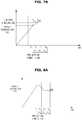
- FIGS. 7A and 7Bare graphs for explaining the proportional control.
- control unit 200compares the target temperature A and a current temperature at the beginning of each period and performs "proportional control" in which it is determined whether on/off times increase or decrease according to whether the current temperature is greater or less than the target temperature A.
- the control unit 200determines whether the target temperature A and a current temperature (i.e., a temperature at T1) are identical or the current temperature exceeds the target temperature A. As illustrated in FIG. 7A , when the current temperature exceeds the target temperature A by A1, the control unit 200 controls the on time of the heater module 60 to be reduced by time Z11 corresponding to A1. On the other hand, as illustrated in FIG. 7B , when the current temperature is less than the target temperature A by A1, the control unit 200 controls the on time of the heater module 60 to be increased by time Z11 corresponding to A1.
- control unit 200decreases the on time of the heater module 60 when the current temperature exceeds the target temperature A and increases the on time of the heater module 60 when the current temperature does not reach the target temperature A, so that the current temperature approximates to the target temperature A.
- Such proportional controlis performed at the beginning of each period. Even at the beginning of a second period P2, i.e., T2, the control unit 200 compares the target temperature A and a current temperature (i.e., a temperature at T2) and performs control such that, as illustrated in FIG. 7A , when the current temperature exceeds the target temperature A by A2, the on time of the heater module 60 is reduced by time Z12 corresponding to A2. On the other hand, as illustrated in FIG. 7B , the control unit 200 performs control such that, when the current temperature is less than the target temperature A by A2, the on time of the heater module 60 is increased by time Z12 corresponding to A2.
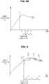
- FIGS. 8A and 8Bare graphs for explaining integral control.
- the control unit 200compares a current temperature and a previous temperature at the beginning of each period and, when the current temperature and the previous temperature are identical, the control unit 200 secondly performs "integral control" in which it is determined whether on/off times of the heater module 60 increase or decrease according to whether the current temperature is greater or less than the target temperature A.
- integral controla state in which a current temperature and a previous temperature are identical may be referred to as a stable state.
- the control unit 200determines whether a current temperature (i.e., a temperature at T4) and a previous temperature (i.e., a temperature at T3) are identical. When the current temperature and the previous temperature are identical, the control unit 200 determines whether the current temperature exceeds the target temperature A.
- the control unit 200controls the on time of the heater module 60 to be increased by time Z24 corresponding to A4. That is, upon reaching a stable state at a point at which a temperature at T4 of the cooking compartment 20 is less than the target temperature A, the control unit 200 increases the temperature of the stable state to be converged to the target temperature A by increasing the on time of the heater module 60.
- the control unit 200controls the on time of the heater module 60 to be decreased by time Z24 corresponding to A4. That is, upon reaching a stable state at a point at which the temperature at T4 of the cooking compartment 20 exceeds the target temperature A, the control unit 200 decreases the temperature of the stable state to be converged to the target temperature A by decreasing the on time of the heater module 60.
- FIG. 9is a graph for explaining differential control.
- control unit 200In a case in which a current temperature and a previous temperature are different when comparing the current temperature and the previous temperature at the beginning of each period, i.e., when not reaching a stable state, the control unit 200 secondly performs "differential control" in which it is determined whether on/off times increase or decrease according to whether the current temperature is greater or less than the previous temperature.
- the control unit 200determines whether a current temperature (i.e., a temperature at T2) exceeds a previous temperature (i.e., a temperature at T1). When the current temperature exceeds the previous temperature by B2, the control unit 200 controls the on time of the heater module 60 to be decreased by time Z32 corresponding to B2. In other words, when an average slope S2 at T2 has a positive (+) value, it may be regarded that the control unit 200 controls the on time of the heater module 60 to be decreased by time Z32 corresponding to S2.
- the control unit 200determines whether a current temperature (i.e., a temperature at T3) exceeds a previous temperature (i.e., a temperature at T2). When the current temperature is less than the previous temperature by B3, the control unit 200 controls the on time of the heater module 60 to be increased by time Z33 ⁇ corresponding to B3. In other words, when an average slope S3 at T3 has a negative (-) value, it may be regarded that the control unit 200 controls the on time of the heater module 60 to be increased by time Z33 corresponding to S3.
- the control unit 200performs control such that the average slope is in a horizontal state, i.e., a stable state by decreasing the on time of the heater module 60 when the average slope has a positive (+) value and increasing the on time of the heater module 60 when the average slope has a negative (-) value.
- the integral control or differential control as described aboveis performed at the beginning of each period similar to the proportional control.
- the control unit 200first performs proportional control such that a current temperature approximates to the target temperature A through comparison between the current temperature and the target temperature A and secondly performs integral control such that a temperature of a stable state is converged to the target temperature A or performs differential control such that a non-stable state is converted to a stable state, through comparison between the current temperature and a previous temperature.
- the control unit 200resets on/off times of each period by accumulating on/off times for the target temperature A extracted from the storage unit 400 and times calculated for proportional control, integral control or differential control.
- the control unit 200may reset the on/off times N1 and F1 of the first period P1 to NX+Z11+Z21 and FX-Z11-Z21, respectively and reset the on/off times N2 and F2 of the second period P2 to N1+Z21-Z31 and F1-Z21+Z31, respectively.
- control unit 200resets the on time N1 of the first period P1 to NX+Z11+Z21 and may reset the off time F1 based on a difference between a total time of the first period P1 and the on time N1. That is, the control unit 200 may reset the off time F1 of the first period P1 to (total time of the first period P1)-N1. Similarly, the control unit 200 resets the on time N2 of the second period P2 to N1+Z21-Z31 and may reset the off time F2 of the second period P2 to (total time of the second period P2)-N2 using the reset on time.
- the control unit 200outputs a control signal to the heater driving unit 300 so that the heater module 60 is driven according to the set on/off times.
- the heater driving unit 300controls on or off operation of the heater module 60 such that the heater module 60 performs heating or stops heating according to the control signal of the control unit 200. For example, when the control unit 200 sets the on/off times for the first period P1 of the heater module 60 at N1 and F1, respectively, the heater driving unit 300 controls on/off operations of the heater module 60 according to the set on/off times such that the heater module 60 operates in an on state for an interval between T1 and N1 and, after N1, the heater module 60 operates in an off state for the off time F1.
- the heater driving unit 300controls on/off operations of the heater module 60 such that the heater module 60 operates in an on state at time T2 for the on time N2 and thereafter operates in an off state for the off time F2.
- control unit 200may also control a period at which the on/off states of the heater module 60 are repeated.
- the control unit 200may also control an interval or frequency at which the on/off states of the heater module 60 are repeated.
- the period at which the on/off states of the heater module 60 are repeatedmay be simply referred to as an on/off period of the heater module 60.
- the control unit 200may set an interval between T1 and T2, which is a first period, an interval between T2 and T3, which is a second period, and an interval between T3 and T4, which is a third period, to 1 minute and output a control signal to the heater driving unit 300 according to the set interval.
- the control unit 200may set an interval of each of the first period, the second period, and the third period to 0.5 minutes and output a control signal to the heater driving unit 200 according to the set interval.
- the control unit 200controls the on/off period of the heater module 60 to be short and thus resolution may be increased and precise control of the control unit 200 is possible.
- the storage unit 400may store data or algorithms for manipulation of the oven 1.
- the storage unit 400may store a sensing period of the temperature sensor 100, a preheating completion time, the target temperature A, and on/off times of the heater module 60 that are preset according to temperature differences.
- the storage unit 400may store on/off increase or decrease times of each period that are calculated by proportional control, integral control, or differential control and final on/off times of each period that are set by accumulating the on/off increase or decrease times.
- the storage unit 400may store an algorithm for calculating on/off increase or decrease times of each period through proportional control, integral control, or differential control and an algorithm for setting final on/off times of each period by accumulating the on/off increase or decrease times.
- the storage unit 400may be a non-volatile memory device such as a read-only memory (ROM), a programmable read-only memory (PROM), an erasable programmable read-only memory (EPROM), or a flash memory, a volatile memory device such as a random access memory (RAM), or a storage device such as a hard disk or an optical disk.
- ROMread-only memory
- PROMprogrammable read-only memory
- EPROMerasable programmable read-only memory
- flash memorya volatile memory device such as a random access memory (RAM), or a storage device such as a hard disk or an optical disk.
- RAMrandom access memory
- FIG. 10illustrates an internal temperature with respect to a target temperature of the cooking compartment 20.
- the target temperatureis set to A1 at the beginning, to A2 after time Tx, and to A3 after time Ty.
- the internal temperature of the cooking compartment 20remains almost the same as the target temperature A1 after preheating is completed and, after increasing to the target temperature A2, rapidly increases and remains almost the same as the target temperature A2. Similarly, it can be confirmed that, when the target temperature is further increased to A3, the internal temperature of the cooking compartment 20 sharply increases and remains almost the same as the target temperature A3.
- the oven 1significantly reduces a temperature ripple phenomenon by resetting on/off times of the heater module 60 according to each period through proportional control, integral control, or differential control.
- the on/off period of the heater module 60is set short during proportional control, integral control, or differential control, which enables precise control of the oven 1.
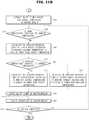
- FIGS. 11A and 11Bare flowcharts illustrating an oven control method according to an embodiment of the present disclosure.
- the target temperature Ais set based on information input by a user (operation 810). After the target temperature A is set, the control unit 200 performs an on operation for preheating of the heater module 60 (operation 811).
- the control unit 200periodically determines whether preheating is completed (operation 812).
- a preheating completion time or a preheating temperatureis pre-set and stored in the storage unit 400, and the control unit 200 determines whether a preheating time reaches the stored preheating completion time or a current temperature of the cooking compartment 20 reaches the stored preheating temperature and determines whether preheating is completed.
- control unit 200When preheating is not completed, the control unit 200 continuously performs the on operation of the heater module 60. When preheating is completed, the control unit 200 extracts on/off times of the heater module 60 that are preset for the target temperature A from the storage unit 400 (operation 813).
- the on/off times of the heater module 60are preset according to temperature differences and stored in the storage unit 400, and the control unit 200 extracts, from the storage unit 400, on/off times corresponding to a difference between the set target temperature A and a temperature at the preheating completion time.
- the control unit 200resets the on/off times for each period of the heater module 60 and controls the heater module 60 to operate according to the on/off times.
- the control unit 200determines whether the target temperature A is identical to a current temperature (operation 814).
- the current temperaturemeans an initial temperature of the corresponding period.
- control unit 200controls the heater module 60 to operate at the same on/off times as those extracted from the storage unit 400 or those of the previous period without resetting the on/off times for the corresponding period (operation 820).
- control unit 200calculates on increase/decrease times of the heater module 60 according to whether the current temperature is greater or less than the target temperature A (operation 815). That is, on increase/decrease times for "proportional control" performed such that the current temperature approximates to the target temperature A are first calculated through comparison between the target temperature A and the current temperature.
- control unit 200determines whether the current temperature and a previous temperature are identical (operation 816).
- the previous temperaturemeans an initial temperature of the previous period.
- control unit 200calculates on increase/decrease times of the heater module 60 according to whether the current temperature is greater or less than the target temperature A (operation 817). That is, on increase/decrease times for "integral control" performed such that a temperature of a stable state is converged to the target temperature A are secondly calculated through comparison between the current temperature and the previous temperature.
- control unit 200calculates on increase/decrease times of the heater module 60 according to whether the current temperature is greater or less than the previous temperature (operation 818). That is, on increase/decrease times for "differential control" performed such that an unstable state is converted to a stable state are calculated.
- the control unit 200resets the on/off times of the heater module 60 by accumulating the on/off times for the target temperature A extracted from the storage unit 400 and the on increase/decrease times calculated for proportional control, integral control, or differential control (operation 819).
- control unit 200may reset the on time N1 of the first period to NX+Z11+Z21 and reset the off time F1 based on a difference between a total time of the first period and the on time N1. That is, the off time F1 of the first period may be reset to (total time of the first period)-Ni. Similarly, the control unit 200 may reset the on time N2 of the second period to N1+Z21-Z31 and reset the off time F2 of the second period to (total time of the second period)-N2 using the reset on time N2.
- control unit 200controls the heater module 60 to operate according to the set on/off times for the corresponding period (operation 820).
- the control unit 200determines whether cooking is completed (operation 821). When cooking is completed, the heater module 60 is stopped. On the other hand, when cooking is incomplete, operation returns to operation 814 to start the next period and then it is determined whether the target temperature A and the current temperature are identical.
- control unit 200resets the on/off times of the heater module 60 according to each period through proportional control, integral control, or differential control, whereby the temperature ripple phenomenon occurring in the oven 1 may be significantly reduced.
- control unit 200sets the on/off period of the heater module 60 short during proportional control, integral control, or differential control, whereby precise control is possible.
- the control unit or controller 200may use one or more processors.
- a processing devicemay be implemented using one or more general-purpose or special purpose computers, and may include, for example, one or more of a processor, a controller and an arithmetic logic unit, a central processing unit (CPU), a graphics processing unit (GPU), a digital signal processor (DSP), an image processor, a microcomputer, a field programmable array, a programmable logic unit, an application-specific integrated circuit (ASIC), a microprocessor or any other device capable of responding to and executing instructions in a defined manner.
- CPUcentral processing unit
- GPUgraphics processing unit
- DSPdigital signal processor
- ASICapplication-specific integrated circuit
Landscapes
- Engineering & Computer Science (AREA)
- Chemical & Material Sciences (AREA)
- Combustion & Propulsion (AREA)
- Mechanical Engineering (AREA)
- General Engineering & Computer Science (AREA)
- Health & Medical Sciences (AREA)
- Nutrition Science (AREA)
- Life Sciences & Earth Sciences (AREA)
- Food Science & Technology (AREA)
- Polymers & Plastics (AREA)
- Electric Stoves And Ranges (AREA)
Description
- The present invention relates to an oven that controls on/off operation of a heater and a method of controlling the same.
- Various electronic products, such as TVs, a washing machine, a refrigerator, an air-conditioner, and the like, are produced to make modern life more comfortable and convenient. Among these electronic products, in particular, cooking appliances enable simple cooking of various foods and thus give convenience to busy professionals or housewives participating in social activities. For this reason, these cooking appliances are essential electronic products for modern people.
- Ovens, which are one form of cooking appliance, cook foods by heat. Such ovens are divided into a gas oven and an electric oven according to heat source. A gas oven uses gas as a heat source and heats and cooks food using flames ignited by a plurality of burners, and an electric oven uses electricity as a heat source and heats and cooks food using heat emitted from a heater. That is, electric ovens use electricity as a heat source and cook food using radiant heat, convection heat, and conduction heat. Such electric ovens simultaneously heat an outside and an inside of food to be cooked and thus exhibit a faster cooking speed, higher thermal efficiency, and stability than gas ovens and, accordingly, use thereof is increasing.
- In general, an electric oven includes a main body that defines an exterior appearance of the oven and has an open front surface through which food to be cooked is introduced into a cooking compartment defined in the main body and a door installed at a front side of the main body so as to selectively open or close the cooking compartment. The door of the electric oven consists of plural pieces of glass to prevent heat in the cooking compartment from being emitted outside and some of the pieces of glass have a heat-reflective coating surface.
US2003/218002 ,US2007/084849 ,AU 2004 255 018 EP 0 275 990US 2013/269539 A1 relates to a variable temperature cooking method that uses a predetermined variable temperature reference profile.- Therefore, it is an aspect of the present disclosure to provide an oven that controls on/off operations of a heater and a method of controlling the oven.
- Additional aspects of the disclosure will be set forth in part in the description which follows and, in part, will be obvious from the description, or may be learned by practice of the disclosure.
- According to an aspect of the present invention, there is provided an oven according to
claim 1. Optional features are set out in the dependent claims. - In accordance with one aspect of the present disclosure, an oven includes at least one heater arranged in a cooking compartment, a temperature sensor to sense a temperature of the cooking compartment every preset period of time, and a control unit to reset on/off times for each period of the heater based on a preset target temperature and a current temperature and previous temperature of the cooking compartment sensed by the temperature sensor and to control the heater to be driven according to the reset on/off times.
- The control unit may control driving of the heater such that the heater is turned on until prior to a preheating completion time and may reset on/off times for a period after the preheating completion time of the heater.
- The current temperature may be a temperature of the cooking compartment at a time at which the corresponding period starts.
- The previous temperature may be a temperature of the cooking compartment at a time at which a previous period starts.
- The oven may further include a storage unit to store on/off times of the heater preset according to temperature differences.
- The control unit may extract the on/off times of the heater stored in the storage unit, based on a difference between the target temperature and a temperature of the cooking compartment at a preheating completion time.
- The control unit may calculate on/off increase or decrease times of the heater based on the target temperature, the current temperature, and the previous temperature.
- The control unit may calculate first on/off increase or decrease times of the heater by comparing the target temperature and the current temperature.
- The control unit may calculate the first on/off increase or decrease times so that, for a period at which the current temperature exceeds the target temperature, the on time of the heater decreases and the off time of the heater increases.
- The control unit may calculate the first on/off increase or decrease times so that, for a period at which the current temperature is lower than the target temperature, the on time of the heater increases and the off time of the heater decreases.
- The control unit may calculate second on/off increase or decrease times of the heater by comparing the current temperature and the previous temperature.
- The control unit may calculate the second on/off increase or decrease times for a period at which the current temperature and the previous temperature are identical, through comparison between the target temperature and the current temperature.
- The control unit may calculate the second on/off increase or decrease times so that, for a period at which the current temperature exceeds the previous temperature, the on time of the heater decreases and the off time of the heater increases.
- The control unit may calculate the second on/off increase or decrease time so that, for a period at which the current temperature is lower than the previous temperature, the on time of the heater increases and the off time of the heater decreases.
- The control unit may reset on/off times of the heater by accumulating the calculated on/off increase or decrease times of the heater to the extracted on/off times.
- The control unit may adjust an interval or frequency of the period.
- In accordance with another aspect of the present disclosure, an oven includes at least one heater installed inside a cooking compartment, a temperature sensor to sense a temperature of the cooking compartment, an input unit through which a target temperature of the cooking compartment is input by a user, and a control unit to control the heater to be turned on until the temperature of the cooking compartment reaches a preheating temperature and to control the heater to be turned on/off based on the target temperature and the temperature of the cooking compartment after the temperature of the cooking compartment reaches the preheating temperature, when the target temperature is input.
- The control unit may control on/off of the heater so that the temperature of the cooking compartment is converged to the target temperature.
- The control unit may periodically set on/off times of the heater and control driving of the heater according to the set on/off times.
- In accordance with another aspect of the present disclosure, a method of controlling an oven includes sensing a temperature of a cooking compartment every preset period of time, the sensing being performed by a temperature sensor, resetting on/off times for each period of a heater based on a preset target temperature and a current temperature and previous temperature of the cooking compartment sensed by the temperature sensor, and controlling driving of the heater according to the reset on/off times.
- The resetting may include controlling the heater to be turned on until prior to a preheating completion time and resetting on/off times for a period after the preheating completion time of the heater.
- The method may further include storing on/off times of the heater preset according to temperature differences.
- The method may further include extracting the on/off times of the heater stored in the storage unit based on a difference between the target temperature and a temperature of the cooking compartment at a preheating completion time.
- The resetting may include calculating on/off increase or decrease times of the heater based on the target temperature, the current temperature, and the previous temperature.
- The resetting may include calculating first on/off increase or decrease times of the heater by comparing the target temperature and the current temperature.
- The calculating of the first on/off increase or decrease times may include calculating first on/off increase or decrease times so that, for a period at which the current temperature exceeds the target temperature, the on time of the heater decreases and the off time of the heater increases.
- The calculating of the first on/off increase or decrease times may include calculating first on/off increase or decrease times so that, for a period at which the current temperature is lower than the target temperature, the on time of the heater increases.
- The resetting may include calculating second on/off increase or decrease times of the heater by comparing the current temperature and the previous temperature.
- The calculating of the second on/off increase or decrease times may include calculating second on/off increase or decrease times for a period at which the current temperature is identical to the previous temperature, through comparison between the target temperature and the current temperature.
- The calculating of the second on/off increase or decrease times may include calculating second on/off increase or decrease times so that, for a period at which the current temperature is higher than the previous temperature, the on time of the heater decreases and the off time of the heater increases.
- The calculating of the second on/off increase or decrease times may include calculating second on/off increase or decrease times so that, for a period at which the current temperature is lower than the previous temperature, the on time of the heater increases and the off time of the heater decreases.
- The resetting may include resetting on/off times of the heater by accumulating the calculated on/off increase or decrease times of the heater to the extracted on/off times.
- The method may further include adjusting an interval or frequency of the period.
- By controlling on/off of the heater using the oven and a control method therefor, a ripple phenomenon occurring because a target temperature does not remain the same may be decreased. Thus, temperature differences may be reduced during cooking of food and, accordingly, cooking ability may be enhanced.
- These and/or other aspects of the disclosure will become apparent and more readily appreciated from the following description of the embodiments, taken in conjunction with the accompanying drawings in which:
FIGS. 1 and2 are perspective views of an oven according to an embodiment of the present disclosure;FIG. 3 is a diagram for explaining a temperature ripple phenomenon occurring according to on/off of a heater module;FIG. 4 is a control block diagram of the oven according to the embodiment of the present disclosure;FIG. 5 is a diagram illustrating time-based control of on/off of the heater module;FIGS. 6A and6B are diagrams for explaining on/off control of each of a plurality of heaters constituting the heater module;FIGS. 7A and7B are diagrams for explaining proportional control;FIGS. 8A and8B are diagrams for explaining integral control;FIG. 9 is a diagram for explaining differential control;FIG. 10 illustrates an internal temperature with respect to a target temperature of a cooking compartment; andFIGS. 11A and11B are flowcharts illustrating an oven control method according to an embodiment of the present disclosure.- Reference will now be made in detail to the embodiments of the present disclosure, examples of which are illustrated in the accompanying drawings, wherein like reference numerals refer to like elements throughout.
- Hereinafter, an oven and a control method therefor according to embodiments of the present disclosure will be described in detail with reference to the accompanying drawings.
FIGS. 1 and2 are perspective views of anoven 1 according to an embodiment of the present disclosure.FIG. 1 is a perspective view illustrating a state in which a door of theoven 1 is closed.FIG. 2 is a perspective view illustrating a state in which the door of theoven 1 is open.- Referring to
FIGS. 1 and2 , theoven 1 includes amain body 10, acooking compartment 20 arranged in themain body 10, and a heating device to heat thecooking compartment 20. - The
main body 10 may be provided at an upper portion thereof with aninput unit 12 through which various commands for cooking are input by a user and adisplay unit 11 to display various cooking information to the user. For example, a user may input commands for starting/ending cooking, selection of cooking menus, cooking time, temperature setting, and the like via theinput unit 12 and may check current time, menu selection screen, operating conditions, cooking progress/remaining time, current temperature, setting temperature, and the like via thedisplay unit 11. - The
input unit 12 may take the form of buttons or rotatable knobs or may be a software form such as a touch screen. Thedisplay unit 11 may be a liquid crystal display (LCD), an organic light emitting diode (OLED), or the like, but embodiments of the present disclosure are not limited thereto. - In
FIG. 1 , theinput unit 12 and thedisplay unit 11 are arranged at an upper rear end of themain body 10. However, in another embodiment, according to user convenience, theinput unit 12 and thedisplay unit 11 may be arranged at an upper front end of themain body 10 or at other portions thereof. That is, the positions of theinput unit 12 and thedisplay unit 11 are not limited. - The
main body 10 may include thecooking compartment 20, which is a space where foods are cooked, and astorage cabinet 14 disposed below thecooking compartment 20 and storing various cooking utensils. - The
storage cabinet 14 may be configured to be inserted and withdrawn along guide rails (not shown), guide grooves (not shown), or the like using ahandle 15 installed at a front surface of thestorage cabinet 14 and rollers (not shown) installed at opposite ends thereof. - The
cooking compartment 20 may have a hexahedral shape with an open surface. In particular, thecooking compartment 20 has anupper surface 21, alower surface 22, arear surface 23, a left-side surface 24, and a right-side surface 25 and a front surface of thecooking compartment 20 may be opened and closed by adoor 90. Thedoor 90 includeshinge elements 30 to be rotatable upward and downward, and a user may open and close thecooking compartment 20 by rotating thedoor 90 while grasping thehandle 92 installed at an upper end of thedoor 90. Installation positions of thehinge elements 30 and thehandle 15 may be different from what is illustrated inFIG. 2 and a rotation direction of thedoor 90 may vary according to the installation positions. - Meanwhile, when the
cooking compartment 20 is opened, foods may be placed in or taken out of thecooking compartment 20. When thecooking compartment 20 is closed, foods may be cooked by heating thecooking compartment 20 according to set values. To check whether food is inside thecooking compartment 20, cooking states of foods, and the like, thedoor 90 may be provided with atransparent window 91 such that the inside of thecooking compartment 20 is visible from outside. - To thermally insulate the
cooking compartment 20 from the outside, theupper surface 21, thelower surface 22, therear surface 23, the left-side surface 24, and the right-side surface 25 of thecooking compartment 20 may be formed of a heat insulating material or may be provided at respective outer sides thereof with heat insulating materials. Likewise, thetransparent window 91 may be formed of a heat insulating material and thedoor 90 may be completely or partially formed of a heat insulating material. - The
cooking compartment 20 is provided with agrill shelf 50 having a lattice shape and detachably arranged to hold food to be cooked and is provided at opposite side surfaces 24 and 25 thereof withsupport bodies 40 to support opposite ends of thegrill shelf 50. As illustrated inFIG. 2 , thegrill shelf 50 may include a plurality ofgrill shelves 50. In addition, thesupport bodies 40 may include at least a pair ofsupport bodies 40, in particular pairs ofsupport bodies 40 having various heights so as to variously adjust installation height of thegrill shelf 50. - The
cooking compartment 20 is provided inside thereof with a heating device to cook foods, and the heating device may include a heater module 60 to perform cooking by directly applying radiation to food and a convection module 70 to perform cooking by circulating heated air. - The heater module 60 may include an
upper heater 61 arranged at theupper surface 21 of thecooking compartment 20 and alower heater 62 arranged at thelower surface 22 of thecooking compartment 20. The convection module 70 may include twoconvection fans rear surface 23 of thecooking compartment 20. The number of heaters constituting the heater module 60 or the number of convection fans constituting the convection module 70 is not limited to the embodiment illustrated inFIG. 2 . - For example, the heater module 60 may further include a rear heater (not shown) coupled to the
convection fans lower heaters convection fans - The heater module 60 allows direct heating of food inside the
cooking compartment 20 through radiation. Theupper heater 61 is arranged at theupper surface 21 of thecooking compartment 20 to be exposed and thus may heat an upper side of the food. Thelower heater 62 is arranged in an unexposed state at thelower surface 22 of thecooking compartment 20 so as to be protected from food, oil generated therefrom, or the like, to heat a lower side of the food. - The convection module 70 shortens cooking time of food by circulating air heated by the heater module 60. In other words, heated air is circulated inside the
cooking compartment 20 as theconvection fans - The convection module 70 may further include a convection fan accommodation unit (not shown) to accommodate the
convection fans partition plates 75 to separate thecooking compartment 20 from theconvection fans cooking compartment 20 from the convection fan accommodation unit. Thepartition plates 75 may be provided with a plurality of holes to suction air of thecooking compartment 20 into the convection fan accommodation unit and to discharge air circulated by theconvection fans cooking compartment 20. - In a general mode, food is cooked by driving only the heater module 60. On the other hand, when rapid cooking or a convection mode is selected by a user, the convection module 70 is driven together with the heater module 60. That is, the
oven 1 cooks food using radiation generated by the heater module 60 and in the convection mode, cooking of the food is assisted by rotation of theconvection fans - In both a general mode and a convection mode, the heater module 60 is basically driven to cook food, and the heater module 60 repeats on and off states so that food is cooked at a set temperature.
- In this regard, when the on/off states of the heater module 60 are repeated, a "temperature ripple phenomenon" in which internal temperature of the
cooking compartment 20 fluctuates in a predetermined range occurs. Conversion of the heater module 60 to the on state or off state does not immediately affect the internal temperature of thecooking compartment 20 and requires a certain period of time to affect the inside of thecooking compartment 20. Thus, when on/off of the heater module 60 is simply controlled at a point at which a temperature set by a user, i.e., a target temperature turns into a +/- delta temperature, an overshoot and an undershoot are repeated based on the target temperature and, accordingly, the temperature ripple phenomenon occurs. This will be described in detail with reference toFIG. 3 . FIG. 3 is a diagram for explaining the temperature ripple phenomenon occurring according to on/off of the heater module 60. In the following description in addition to the description with reference toFIG. 3 , a temperature set via theinput unit 12 is denoted as a target temperature A.- As illustrated in
FIG. 3 , the heater module 60 increases the internal temperature of thecooking compartment 20 while maintaining an on state to a time T1 at which preheating is completed. When a temperature at which preheating is completed (hereinafter, referred to as a preheating temperature) is unable to reach the target temperature A, the heater module 60 further maintains the on state for a predetermined period of time to allow the current temperature to approximate to the target temperature A. The heater module 60 is converted to an off state at a time Tx at which the current temperature reaches the target temperature A or immediately before the time Tx. In this regard, the internal temperature of thecooking compartment 20 exceeds the target temperature A by remaining heat of the heater module 60, and a predetermined period of time is needed until the target temperature A is reached. That is, an overshoot appears based on the target temperature A. - Meanwhile, to maintain the target temperature A, the heater module 60 is converted again to the on state at a time Ty at which the current temperature coincides with the target temperature A or immediately therebefore. Since time to heat the heater module 60 is required, the internal temperature of the
cooking compartment 20 is reduced to less than the target temperature A and a predetermined period of time is needed to reach the target temperature A. That is, an undershoot appears based on the target temperature A. - As such, while on/off of the heater module 60 is repeated, the internal temperature of the
cooking compartment 20 fluctuates in a predetermined range R such that the target temperature A does not remain the same until cooking is completed and the internal temperature exceeds the target temperature A or is reduced to less than the target temperature A. That is, a ripple phenomenon of the internal temperature of thecooking compartment 20 may occur. The temperature ripple phenomenon may increasingly or decreasingly occur according to on/off time or conversion time of on/off. In other words, the internal temperature of thecooking compartment 20 may fluctuate more widely or more narrowly according to how to control the on/off times of the heater module 60. - Hereinafter, elements of the
oven 1 that enable reduction in the temperature ripple phenomenon through control of the on/off times of the heater module 60 and function of each element will be described. FIG. 4 is a control block diagram of theoven 1 according to the embodiment of the present disclosure.- Referring to
FIG. 4 , theoven 1 includes theinput unit 12, thedisplay unit 11, atemperature sensor 100, acontrol unit 200, aheater driving unit 300, and astorage unit 400. - As described above, the
input unit 12 receives various commands for cooking from a user and thedisplay unit 11 displays various cooking information to a user. A user may set the target temperature A needed for cooking through theinput unit 12 and may check the set target temperature A via thedisplay unit 11. - The
temperature sensor 100 is installed in thecooking compartment 20 to sense the internal temperature of thecooking compartment 20 that varies according to on/off of the heater module 60. In particular, thetemperature sensor 100 may be installed at at least one of theupper surface 21, thelower surface 22, therear surface 23, the left-side surface 24, and the right-side surface 25 of thecooking compartment 20 and periodically senses the internal temperature of thecooking compartment 20 until cooking is completed. Temperature sensed by thetemperature sensor 100 is transmitted to thecontrol unit 200, and thecontrol unit 200 controls on/off times of the heater module 60 based on the sensed temperature. Temperature sensing of thetemperature sensor 100 and function of thecontrol unit 200 based thereon will be described below. - The
temperature sensor 100 may be a contact-type temperature sensor or a noncontact-type temperature sensor. In particular, thetemperature sensor 100 may be at least one of a resistance temperature detector (RTD) temperature sensor using changes in resistance of a metal according to temperature changes, a thermistor temperature sensor using changes in resistance of a semiconductor according to temperature changes, a thermocouple temperature sensor using electromotive force generated at opposite ends of a junction between two metal wires of different materials, and an integrated circuit (IC) temperature sensor using voltage at opposite terminals of a transistor that varies according to temperature or current-voltage characteristics of a P-N junction unit thereof. However, embodiments of the present disclosure are not limited to the above examples and thetemperature sensor 100 may be any other type of sensor so long as the sensor is able to sense the internal temperature of thecooking compartment 20. - The
control unit 200 controls on/off times or time at which the on/off states are sustained of the heater module 60, based on the internal temperature of thecooking compartment 20. FIG. 5 is a diagram illustrating time-based control of on/off of the heater module 60.FIGS. 6A and6B are diagrams for explaining on/off control of each of a plurality of heaters constituting the heater module 60.- Referring to
FIG. 5 , thecontrol unit 200 turns the heater module 60 on and starts preheating to cook food. In addition, thecontrol unit 200 determines whether a time to sustain the on state of the heater module 60 reaches a preheating completion time T1 or whether the internal temperature of thecooking compartment 20 reaches a preheating temperature. For this operation, the preheating completion time T1 or the preheating temperature is preset and stored in thestorage unit 400. For convenience of explanation, hereinafter, a case in which the preheating completion time T1 is pre-stored in thestorage unit 400 and thecontrol unit 200 determines whether or not preheating is completed, using the preheating completion time T1 will be described. - When determining that the preheating completion time T1 is reached, the
control unit 200 sets on/off times of the heater module 60 according to each period and controls the heater module 60 to perform on/off according to the set on/off times. In this regard, the "on" time of the heater module 60 means a time at which the on state of the heater module 60 is sustained, and the "off' time of the heater module 60 means a time at which the off state of the heater module 60 is sustained. - As described above, the
temperature sensor 100 periodically senses the internal temperature of thecooking compartment 20 from a preheating start time to a time at which cooking is completed and transmits the sensed temperature information to thecontrol unit 200. In this regard, a sensing period of thetemperature sensor 100 is pre-set and stored in thestorage unit 400. The sensing period need not be constant and sensing periods prior to and after the preheating completion time T1 may be differently set. - For example, the
temperature sensor 100 senses the temperature of thecooking compartment 20 at times T1, T2, T3, and T4, and an interval between T1 and T2, an interval between T2 and T3, and an interval between T3 to T4 may be constant or differently set. In this regard, the interval between T1 and T2 may be defined as a first period, the interval between T2 and T3 may be defined as a second period, and the interval between T3 and T4 may be defined as a third period. In addition, thetemperature sensor 100 also senses the internal temperature of thecooking compartment 20 prior to the preheating completion time T1. - The
control unit 200 sets on/off times of the heater module 60 according to each period, based on the temperature sensed by thetemperature sensor 100. - In particular, the
control unit 200 sets the on/off times for the first period of the heater module 60 at the preheating completion time T1 by comparing the target temperature A input by a user, a current temperature sensed by thetemperature sensor 100 at T1, and a previous temperature sensed by thetemperature sensor 100 before T1. In addition, thecontrol unit 200 sets the on/off times for the second period of the heater module 60 at a time T2 at which the first period is completed by comparing the target temperature A, a current temperature sensed by thetemperature sensor 100 at T2, and a previous temperature sensed by thetemperature sensor 100 before T2, i.e., a temperature sensed by thetemperature sensor 100 at T1. - Similarly, the
control unit 200 sets the on/off time for the third period of the heater module 60 at a second period completion time T3 by comparing the target temperature A, a current temperature sensed by thetemperature sensor 100 at T3, and a previous temperature sensed by thetemperature sensor 100 before T3, i.e., a temperature sensed by thetemperature sensor 100 at T2. - As described above, the
control unit 200 may compare the target temperature A, a current temperature and a previous temperature every period and set on/off times for operation of the heater module 60 at the corresponding period through the comparison. A method of comparing the target temperature A, a current temperature, and a previous temperature every period, performed by thecontrol unit 200 and a method of setting on/off times by comparison thereamong will be described below in further detail. - The
control unit 200 controls the heater module 60 to be driven according to set time. In particular, when the on time and off time for the first period of the heater module 60 are set at N1 and F1, respectively, thecontrol unit 200 controls the heater module 60 to maintain the on state for an interval between T1 and N1 and to convert the on state to an off state after N1 elapses and maintain F1. When the on time and off time for the second period of the heater module 60 are set at N2 and F2, respectively, thecontrol unit 200 controls the heater module 60 to perform conversion to an on state at T2 and maintain the on state for N2 and to convert the on state to an off state and maintain the off state for F2. - Similarly, when the on time and off time for the third period of the heater module 60 are set at N3 and F3, respectively, the
control unit 200 controls the heater module 60 to perform conversion to an on state at T3 and maintain the on state for N3 and to maintain an off state for F3. As such, thecontrol unit 200 resets on/off times at the beginning of each period and thus the on/off times may vary according to each period. For example, the on time N1 of the first period, the on time N2 of the second period and the on time N3 of the third period of the heater module 60 may be differently set. - As illustrated in
FIGS. 6A and6B , thecontrol unit 200 may set on/off times according to each heater constituting the heater module 60 and control the heater module 60 to be driven according to the on/off times of each heater. In other words, thecontrol unit 200 may set, at the preheating completion time T1, on/off times of the first period of theupper heater 61 at N11 and F11, respectively and on/off times of the first period of thelower heater 62 at N21 and F21, respectively. In addition, thecontrol unit 200 may set, at the first period completion time T2, on/off times of the second period of theupper heater 61 at N12 and F12, respectively and on/off times of the second period of thelower heater 62 at N22 and F22, respectively. - Similarly, the
control unit 200 may set, at the second period completion time T3, on/off times of the third period of theupper heater 61 at N13 and F13, respectively and on/off times of the third period of thelower heater 62 at N23 and F23, respectively. Thus, the on/off times may vary according to position of each heater or according to each heater even at the same period. For example, the on time N11 for the first period of theupper heater 61 and the on time N21 for the first period of thelower heater 62 may be differently set. - As described above, even when the on/off times are set according to each heater, the
control unit 200 sets the on/off times for each period through comparison among the target temperature A, a current temperature, and a previous temperature. Hereinafter, a method of setting the on/off times for each period through comparison among the target temperature A, a current temperature, and a previous temperature will be described in detail. For convenience of explanation, a case in which on/off times of all the heaters are set to the same value instead of setting on/off times according to each heater will be described below. - The
control unit 200 extracts the on/off times of the heater module 60 that are preset according to the target temperature A and stored in thestorage unit 400 from thestorage unit 400. For example, the on/off times for a temperature difference x are respectively preset at Nx and Fx and stored in thestorage unit 400 and, when the input target temperature A exceeds a temperature at the preheating completion time by x, thecontrol unit 200 extracts the on time Nx and the off time Fx from thestorage unit 400. - The
control unit 200 compares the target temperature A and a current temperature at the beginning of each period and first determines whether the on/off times increase or decrease according to whether the current temperature is higher or lower than the target temperature. This may be simply referred to as "proportional control," and the on/off times that increase or decrease by the proportional control may be defined as ±Z1j where j represents a period. - In addition, the
control unit 200 compares a current temperature and a previous temperature at the beginning of each period. When the current temperature and the previous temperature are identical, i.e., when the temperature is stable, thecontrol unit 200 secondly determines whether the on/off times increase or decrease according to whether the current temperature is greater or less than the target temperature A. This may be referred to as "integral control," and the on/off times that increase or decrease by the integral control may be defined as ±Z2j where j represents a period. - When the current temperature and the previous temperature are different, the
control unit 200 secondly determines whether the on/off times increase or decrease according to whether the current temperature is greater or less than the previous temperature. This may be referred to as "differential control," and the on/off times that increase or decrease by the differential control may be defined as ±Z3j where j represents a period. The proportional control, integral control and differential control of thecontrol unit 200 will be described below in further detail with reference toFIGS. 7A to 9 .FIGS. 7A and7B are graphs for explaining the proportional control. - As described above, the
control unit 200 compares the target temperature A and a current temperature at the beginning of each period and performs "proportional control" in which it is determined whether on/off times increase or decrease according to whether the current temperature is greater or less than the target temperature A. - In particular, at the beginning of a first period P1, i.e., the preheating completion time T1, the
control unit 200 determines whether the target temperature A and a current temperature (i.e., a temperature at T1) are identical or the current temperature exceeds the target temperature A. As illustrated inFIG. 7A , when the current temperature exceeds the target temperature A by A1, thecontrol unit 200 controls the on time of the heater module 60 to be reduced by time Z11 corresponding to A1. On the other hand, as illustrated inFIG. 7B , when the current temperature is less than the target temperature A by A1, thecontrol unit 200 controls the on time of the heater module 60 to be increased by time Z11 corresponding to A1. - In other words, the
control unit 200 decreases the on time of the heater module 60 when the current temperature exceeds the target temperature A and increases the on time of the heater module 60 when the current temperature does not reach the target temperature A, so that the current temperature approximates to the target temperature A. - Such proportional control is performed at the beginning of each period. Even at the beginning of a second period P2, i.e., T2, the
control unit 200 compares the target temperature A and a current temperature (i.e., a temperature at T2) and performs control such that, as illustrated inFIG. 7A , when the current temperature exceeds the target temperature A by A2, the on time of the heater module 60 is reduced by time Z12 corresponding to A2. On the other hand, as illustrated inFIG. 7B , thecontrol unit 200 performs control such that, when the current temperature is less than the target temperature A by A2, the on time of the heater module 60 is increased by time Z12 corresponding to A2. FIGS. 8A and8B are graphs for explaining integral control.- The
control unit 200 compares a current temperature and a previous temperature at the beginning of each period and, when the current temperature and the previous temperature are identical, thecontrol unit 200 secondly performs "integral control" in which it is determined whether on/off times of the heater module 60 increase or decrease according to whether the current temperature is greater or less than the target temperature A. As described above, a state in which a current temperature and a previous temperature are identical may be referred to as a stable state. - For example, at a time T4 of a fourth period, the
control unit 200 determines whether a current temperature (i.e., a temperature at T4) and a previous temperature (i.e., a temperature at T3) are identical. When the current temperature and the previous temperature are identical, thecontrol unit 200 determines whether the current temperature exceeds the target temperature A. - As illustrated in
FIG. 8A , when the current temperature and the previous temperature are identical and the current temperature is less than the target temperature A by A4, thecontrol unit 200 controls the on time of the heater module 60 to be increased by time Z24 corresponding to A4. That is, upon reaching a stable state at a point at which a temperature at T4 of thecooking compartment 20 is less than the target temperature A, thecontrol unit 200 increases the temperature of the stable state to be converged to the target temperature A by increasing the on time of the heater module 60. - As illustrated in
FIG. 8B , when the current temperature and the previous temperature are the same and the current temperature exceeds the target temperature A by A4, thecontrol unit 200 controls the on time of the heater module 60 to be decreased by time Z24 corresponding to A4. That is, upon reaching a stable state at a point at which the temperature at T4 of thecooking compartment 20 exceeds the target temperature A, thecontrol unit 200 decreases the temperature of the stable state to be converged to the target temperature A by decreasing the on time of the heater module 60. FIG. 9 is a graph for explaining differential control.- In a case in which a current temperature and a previous temperature are different when comparing the current temperature and the previous temperature at the beginning of each period, i.e., when not reaching a stable state, the
control unit 200 secondly performs "differential control" in which it is determined whether on/off times increase or decrease according to whether the current temperature is greater or less than the previous temperature. - As illustrated in
FIG. 9 , when not in a stable state at time T2 of the second period P2, thecontrol unit 200 determines whether a current temperature (i.e., a temperature at T2) exceeds a previous temperature (i.e., a temperature at T1). When the current temperature exceeds the previous temperature by B2, thecontrol unit 200 controls the on time of the heater module 60 to be decreased by time Z32 corresponding to B2. In other words, when an average slope S2 at T2 has a positive (+) value, it may be regarded that thecontrol unit 200 controls the on time of the heater module 60 to be decreased by time Z32 corresponding to S2. - Similarly, when not in a stable state at time T3 of the third period P3, the
control unit 200 determines whether a current temperature (i.e., a temperature at T3) exceeds a previous temperature (i.e., a temperature at T2). When the current temperature is less than the previous temperature by B3, thecontrol unit 200 controls the on time of the heater module 60 to be increased by time Z33¬ corresponding to B3. In other words, when an average slope S3 at T3 has a negative (-) value, it may be regarded that thecontrol unit 200 controls the on time of the heater module 60 to be increased by time Z33 corresponding to S3. - The
control unit 200 performs control such that the average slope is in a horizontal state, i.e., a stable state by decreasing the on time of the heater module 60 when the average slope has a positive (+) value and increasing the on time of the heater module 60 when the average slope has a negative (-) value. - The integral control or differential control as described above is performed at the beginning of each period similar to the proportional control. Thus, at the beginning of each period, the
control unit 200 first performs proportional control such that a current temperature approximates to the target temperature A through comparison between the current temperature and the target temperature A and secondly performs integral control such that a temperature of a stable state is converged to the target temperature A or performs differential control such that a non-stable state is converted to a stable state, through comparison between the current temperature and a previous temperature. - The
control unit 200 resets on/off times of each period by accumulating on/off times for the target temperature A extracted from thestorage unit 400 and times calculated for proportional control, integral control or differential control. - For example, assuming that the on/off times extracted for the target temperature A are Nx and Fx, a proportional control time +Z11 for the first period P1 is first calculated and an integral control time +Z12 for the first period P1 is secondly calculated, and a proportional control time +Z21 for the second period P2 is first calculated and a differential control time -Z31 for the second period P2 is secondly calculated, the
control unit 200 may reset the on/off times N1 and F1 of the first period P1 to NX+Z11+Z21 and FX-Z11-Z21, respectively and reset the on/off times N2 and F2 of the second period P2 to N1+Z21-Z31 and F1-Z21+Z31, respectively. - In this regard, the
control unit 200 resets the on time N1 of the first period P1 to NX+Z11+Z21 and may reset the off time F1 based on a difference between a total time of the first period P1 and the on time N1. That is, thecontrol unit 200 may reset the off time F1 of the first period P1 to (total time of the first period P1)-N1. Similarly, thecontrol unit 200 resets the on time N2 of the second period P2 to N1+Z21-Z31 and may reset the off time F2 of the second period P2 to (total time of the second period P2)-N2 using the reset on time. - The
control unit 200 outputs a control signal to theheater driving unit 300 so that the heater module 60 is driven according to the set on/off times. - The
heater driving unit 300 controls on or off operation of the heater module 60 such that the heater module 60 performs heating or stops heating according to the control signal of thecontrol unit 200. For example, when thecontrol unit 200 sets the on/off times for the first period P1 of the heater module 60 at N1 and F1, respectively, theheater driving unit 300 controls on/off operations of the heater module 60 according to the set on/off times such that the heater module 60 operates in an on state for an interval between T1 and N1 and, after N1, the heater module 60 operates in an off state for the off time F1. In addition, when thecontrol unit 200 sets the on/off times for the second period P2 of the heater module 60 at N2 and F2, respectively, theheater driving unit 300 controls on/off operations of the heater module 60 such that the heater module 60 operates in an on state at time T2 for the on time N2 and thereafter operates in an off state for the off time F2. - Such control of the on/off operations of the
heater driving unit 300 continues until cooking is completed. In addition, thecontrol unit 200 may also control a period at which the on/off states of the heater module 60 are repeated. Thecontrol unit 200 may also control an interval or frequency at which the on/off states of the heater module 60 are repeated. In this regard, the period at which the on/off states of the heater module 60 are repeated may be simply referred to as an on/off period of the heater module 60. - Referring back to
FIG. 5 , in an embodiment, thecontrol unit 200 may set an interval between T1 and T2, which is a first period, an interval between T2 and T3, which is a second period, and an interval between T3 and T4, which is a third period, to 1 minute and output a control signal to theheater driving unit 300 according to the set interval. In another embodiment, thecontrol unit 200 may set an interval of each of the first period, the second period, and the third period to 0.5 minutes and output a control signal to theheater driving unit 200 according to the set interval. As described above, thecontrol unit 200 controls the on/off period of the heater module 60 to be short and thus resolution may be increased and precise control of thecontrol unit 200 is possible. - The
storage unit 400 may store data or algorithms for manipulation of theoven 1. For example, thestorage unit 400 may store a sensing period of thetemperature sensor 100, a preheating completion time, the target temperature A, and on/off times of the heater module 60 that are preset according to temperature differences. As another example of storage of data, thestorage unit 400 may store on/off increase or decrease times of each period that are calculated by proportional control, integral control, or differential control and final on/off times of each period that are set by accumulating the on/off increase or decrease times. - As an example of storage of algorithms, the
storage unit 400 may store an algorithm for calculating on/off increase or decrease times of each period through proportional control, integral control, or differential control and an algorithm for setting final on/off times of each period by accumulating the on/off increase or decrease times. - The
storage unit 400 may be a non-volatile memory device such as a read-only memory (ROM), a programmable read-only memory (PROM), an erasable programmable read-only memory (EPROM), or a flash memory, a volatile memory device such as a random access memory (RAM), or a storage device such as a hard disk or an optical disk. However, embodiments of the present disclosure are not limited to the above examples and any other types of storage devices known in the art may be used.FIG. 10 illustrates an internal temperature with respect to a target temperature of thecooking compartment 20. - As illustrated in
FIG. 10 , the target temperature is set to A1 at the beginning, to A2 after time Tx, and to A3 after time Ty. - The internal temperature of the
cooking compartment 20 remains almost the same as the target temperature A1 after preheating is completed and, after increasing to the target temperature A2, rapidly increases and remains almost the same as the target temperature A2. Similarly, it can be confirmed that, when the target temperature is further increased to A3, the internal temperature of thecooking compartment 20 sharply increases and remains almost the same as the target temperature A3. - As can be confirmed by
FIG. 10 , theoven 1 significantly reduces a temperature ripple phenomenon by resetting on/off times of the heater module 60 according to each period through proportional control, integral control, or differential control. In addition, in theoven 1, the on/off period of the heater module 60 is set short during proportional control, integral control, or differential control, which enables precise control of theoven 1. - Hereinbefore, elements of the
oven 1 and functions thereof have been described based on embodiments of the present disclosure. Hereinafter, a method of controlling the oven will be described with reference to the given flowchart. FIGS. 11A and11B are flowcharts illustrating an oven control method according to an embodiment of the present disclosure.- Referring to
FIGS. 11A and11B , the target temperature A is set based on information input by a user (operation 810). After the target temperature A is set, thecontrol unit 200 performs an on operation for preheating of the heater module 60 (operation 811). - The
control unit 200 periodically determines whether preheating is completed (operation 812). - A preheating completion time or a preheating temperature is pre-set and stored in the
storage unit 400, and thecontrol unit 200 determines whether a preheating time reaches the stored preheating completion time or a current temperature of thecooking compartment 20 reaches the stored preheating temperature and determines whether preheating is completed. - When preheating is not completed, the
control unit 200 continuously performs the on operation of the heater module 60.
When preheating is completed, thecontrol unit 200 extracts on/off times of the heater module 60 that are preset for the target temperature A from the storage unit 400 (operation 813). - In other words, the on/off times of the heater module 60 are preset according to temperature differences and stored in the
storage unit 400, and thecontrol unit 200 extracts, from thestorage unit 400, on/off times corresponding to a difference between the set target temperature A and a temperature at the preheating completion time. - The
control unit 200 resets the on/off times for each period of the heater module 60 and controls the heater module 60 to operate according to the on/off times. - In particular, first, the
control unit 200 determines whether the target temperature A is identical to a current temperature (operation 814). In this regard, the current temperature means an initial temperature of the corresponding period. - When the target temperature A and the current temperature are identical, the
control unit 200 controls the heater module 60 to operate at the same on/off times as those extracted from thestorage unit 400 or those of the previous period without resetting the on/off times for the corresponding period (operation 820). - When the target temperature A and the current temperature are different, the
control unit 200 calculates on increase/decrease times of the heater module 60 according to whether the current temperature is greater or less than the target temperature A (operation 815). That is, on increase/decrease times for "proportional control" performed such that the current temperature approximates to the target temperature A are first calculated through comparison between the target temperature A and the current temperature. - Next, the
control unit 200 determines whether the current temperature and a previous temperature are identical (operation 816). In this regard, the previous temperature means an initial temperature of the previous period. - When the current temperature and the previous temperature are identical, the
control unit 200 calculates on increase/decrease times of the heater module 60 according to whether the current temperature is greater or less than the target temperature A (operation 817). That is, on increase/decrease times for "integral control" performed such that a temperature of a stable state is converged to the target temperature A are secondly calculated through comparison between the current temperature and the previous temperature. - When the current temperature and the previous temperature are different, the
control unit 200 calculates on increase/decrease times of the heater module 60 according to whether the current temperature is greater or less than the previous temperature (operation 818). That is, on increase/decrease times for "differential control" performed such that an unstable state is converted to a stable state are calculated. - The
control unit 200 resets the on/off times of the heater module 60 by accumulating the on/off times for the target temperature A extracted from thestorage unit 400 and the on increase/decrease times calculated for proportional control, integral control, or differential control (operation 819). - For example, assuming that the extracted on/off times for the target temperature A are Nx and Fx, respectively, a proportional control time +Z11 for the first period is first obtained and an integral control time +Z12 for the first period P1 is secondly obtained, and a proportional control time +Z21 for the second period is first obtained and a differential control time -Z31 for the second period is secondly obtained, the
control unit 200 may reset the on/off times N1 and F1 of the first period to NX+Z11+Z21 and F1=Fx-Z11-Z21, respectively and reset the on/off times N2 and F2 of the second period to N1+Z21-Z31 and F1-Z21+Z31, respectively. - In this regard, the
control unit 200 may reset the on time N1 of the first period to NX+Z11+Z21 and reset the off time F1 based on a difference between a total time of the first period and the on time N1. That is, the off time F1 of the first period may be reset to (total time of the first period)-Ni. Similarly, thecontrol unit 200 may reset the on time N2 of the second period to N1+Z21-Z31 and reset the off time F2 of the second period to (total time of the second period)-N2 using the reset on time N2. - Next, the
control unit 200 controls the heater module 60 to operate according to the set on/off times for the corresponding period (operation 820). - At a time at which the corresponding period is completed, the
control unit 200 determines whether cooking is completed (operation 821). When cooking is completed, the heater module 60 is stopped. On the other hand, when cooking is incomplete, operation returns tooperation 814 to start the next period and then it is determined whether the target temperature A and the current temperature are identical. - As such, the
control unit 200 resets the on/off times of the heater module 60 according to each period through proportional control, integral control, or differential control, whereby the temperature ripple phenomenon occurring in theoven 1 may be significantly reduced. In addition, thecontrol unit 200 sets the on/off period of the heater module 60 short during proportional control, integral control, or differential control, whereby precise control is possible. - The control unit or
controller 200 according to the above-described example embodiments may use one or more processors. For example, a processing device may be implemented using one or more general-purpose or special purpose computers, and may include, for example, one or more of a processor, a controller and an arithmetic logic unit, a central processing unit (CPU), a graphics processing unit (GPU), a digital signal processor (DSP), an image processor, a microcomputer, a field programmable array, a programmable logic unit, an application-specific integrated circuit (ASIC), a microprocessor or any other device capable of responding to and executing instructions in a defined manner. - Although a few embodiments of the present invention have been shown and described, it would be appreciated by those skilled in the art that changes may be made in these embodiments without departing from the scope of which is defined in the claims.
Claims (14)
- An oven (1) comprising:a heater (61, 62) arranged in a cooking compartment (20);a temperature sensor (100) to sense a temperature of the cooking compartment at the beginning of each of a plurality of preset periods (T) of time; anda controller (200) configured to reset on/off times (N, F) of the heater for each of the plurality of preset periods at the beginning of each of the preset period based on a preset target temperature and a current temperature and a previous temperature of the cooking compartment, sensed by the temperature sensor,wherein the on/off times comprise an on time of the heater during which the heater remains turned on and an off time of the heater during which the heater remains turned off, andwherein the controller is further configured to control a driving of the heater according to the reset on/off times, such that the duration of the each of the plurality of preset periods is adjustable according to the duration of the on/off times.
- The oven according to claim 1, wherein the controller controls the driving of the heater such that the heater is turned on until prior to a preheating completion time and resets the on/off times for a preset period of the plurality of preset periods after the preheating completion time of the heater.
- The oven according to claim 1 or 2, further comprising a storage unit (400) to store the on/off times of the heater preset according to temperature differences.
- The oven according to claim 3, wherein the controller extracts the on/off times of the heater stored in the storage unit, based on a difference between the preset target temperature and a temperature of the cooking compartment at a preheating completion time.
- The oven according to claim 4, wherein the controller calculates an increase or a decrease of the on/off times of the heater based on the preset target temperature, the current temperature, and the previous temperature.
- The oven according to claim 4, wherein the controller calculates a first increase or decrease of the on/off times of the heater by comparing the preset target temperature and the current temperature.
- The oven according to claim 6, wherein the controller calculates the first increase or decrease of the on/off times so that, for a period at which the current temperature exceeds the preset target temperature, the on time of the heater decreases and the off time of the heater increases.
- The oven according to claim 6, wherein the controller calculates the first increase or decrease of the on/off times so that, for a period at which the current temperature is lower than the preset target temperature, the on time of the heater increases and the off time of the heater decreases.
- The oven according to claim 6, wherein the controller calculates a second increase or decrease of the on/off times of the heater by comparing the current temperature and the previous temperature.
- The oven according to claim 9, wherein the controller calculates the second increase or decrease of the on/off times for a period of time at which the current temperature and the previous temperature are identical, through comparison between the preset target temperature and the current temperature.
- The oven according to claim 9, wherein the controller calculates the second increase or decrease of the on/off times so that, for a period of time at which the current temperature exceeds the previous temperature, the on time of the heater decreases and the off time of the heater increases.
- The oven according to claim 9, wherein the controller calculates the second increase or decrease of on/off times so that, for a period of time at which the current temperature is lower than the previous temperature, the on time of the heater increases and the off time of the heater decreases.
- The oven according to claim 5, wherein the controller resets the on/off times of the heater by accumulating the calculated increase or decrease of the on/off times of the heater to the extracted on/off times.
- The oven according to any one of the preceding claims, further comprising an input unit (12) through which the target temperature of the cooking compartment is input.
Applications Claiming Priority (1)
| Application Number | Priority Date | Filing Date | Title |
|---|---|---|---|
| KR1020140044306AKR102207463B1 (en) | 2014-04-14 | 2014-04-14 | Oven and method for controlling the same |
Publications (2)
| Publication Number | Publication Date |
|---|---|
| EP2933566A1 EP2933566A1 (en) | 2015-10-21 |
| EP2933566B1true EP2933566B1 (en) | 2021-08-18 |
Family
ID=52823555
Family Applications (1)
| Application Number | Title | Priority Date | Filing Date |
|---|---|---|---|
| EP15163408.6AActiveEP2933566B1 (en) | 2014-04-14 | 2015-04-13 | Oven and method for controlling the same |
Country Status (3)
| Country | Link |
|---|---|
| US (1) | US10082297B2 (en) |
| EP (1) | EP2933566B1 (en) |
| KR (1) | KR102207463B1 (en) |
Families Citing this family (25)
| Publication number | Priority date | Publication date | Assignee | Title |
|---|---|---|---|---|
| US20190234617A1 (en)* | 2015-05-05 | 2019-08-01 | June Life, Inc. | Connected food preparation system and method of use |
| EP3292738B1 (en) | 2015-05-05 | 2020-12-30 | June Life, Inc. | A connected oven |
| CN105011779A (en)* | 2015-07-28 | 2015-11-04 | 中山市马迅电器有限公司 | Baking working method of electric oven |
| US11766151B2 (en) | 2016-02-18 | 2023-09-26 | Meyer Intellectual Properties Ltd. | Cooking system with error detection |
| KR102128768B1 (en) | 2016-02-18 | 2020-07-02 | 마이어 인텔렉츄얼 프로퍼티즈 리미티드 | Auxiliary button for cooking system |
| US20170332676A1 (en)* | 2016-05-23 | 2017-11-23 | Innit International S.C.A. | Dynamic Power Management System, Method And Temperature Control For Conditioners |
| US10721948B1 (en) | 2017-02-08 | 2020-07-28 | Electrolux Home Products, Inc. | Air sous-vide |
| KR102017041B1 (en)* | 2019-01-22 | 2019-09-02 | (주) 피큐아이넷 | Temperature Control System and Method of Grill |
| CN212346260U (en) | 2019-02-26 | 2021-01-15 | 沙克忍者运营有限责任公司 | Cooking system capable of being positioned on a support surface and mountable cooking system |
| EP4061187B8 (en) | 2019-11-20 | 2025-06-18 | June Life, LLC | Method for estimating foodstuff completion time |
| CN113491454A (en) | 2020-04-06 | 2021-10-12 | 沙克忍者运营有限责任公司 | Cooking system positionable on a support surface |
| CN111616167B (en)* | 2020-05-27 | 2021-09-03 | 广东智源机器人科技有限公司 | Oven temperature control method and system, oven and storage medium |
| KR20220004356A (en) | 2020-07-03 | 2022-01-11 | 엘지전자 주식회사 | Method for controling cooking appliance |
| CN112656214B (en)* | 2020-12-17 | 2023-02-21 | 华帝股份有限公司 | Drinking water integrated cooking system and preheating control method |
| EP4019848B1 (en)* | 2020-12-22 | 2024-05-15 | Electrolux Appliances Aktiebolag | Method for operating a cooking oven |
| US11578873B2 (en) | 2021-03-29 | 2023-02-14 | Haier Us Appliance Solutions, Inc. | Oven appliance and method for preheating high-heat cooking surface |
| US12383097B2 (en) | 2021-06-14 | 2025-08-12 | Sharkninja Operating Llc | Temperature controlled accessory for countertop cooking system |
| US12117180B2 (en) | 2021-09-23 | 2024-10-15 | Haier Us Appliance Solutions, Inc. | Oven appliance having a modular trim assembly for collecting debris |
| US12298013B2 (en) | 2021-11-04 | 2025-05-13 | Haier Us Appliance Solutions, Inc. | Oven appliance and methods of state-contingent operation |
| CN118119794A (en)* | 2021-12-16 | 2024-05-31 | 三星电子株式会社 | Apparatus and method for constant temperature cooking in an oven using convective heat |
| US20230213206A1 (en)* | 2022-01-05 | 2023-07-06 | Lg Electronics Inc. | Cooking appliance and method for controlling the same |
| US12352452B2 (en) | 2022-02-28 | 2025-07-08 | Haier Us Appliance Solutions, Inc. | Oven appliance and methods for adaptive cooking |
| US12111061B2 (en) | 2022-02-28 | 2024-10-08 | Haier Us Appliance Solutions, Inc. | Oven appliances and methods for displaying pre-cooking progress |
| US12372247B2 (en) | 2023-04-26 | 2025-07-29 | Sharkninja Operating Llc | Systems and methods for cooking pizza |
| US12035845B1 (en)* | 2023-04-26 | 2024-07-16 | Sharkninja Operating Llc | Systems and methods for cooking pizza |
Citations (1)
| Publication number | Priority date | Publication date | Assignee | Title |
|---|---|---|---|---|
| US20130269539A1 (en)* | 2011-09-17 | 2013-10-17 | B. Robert Polt | Variable Temperature Cooking Method and Apparatus |
Family Cites Families (118)
| Publication number | Priority date | Publication date | Assignee | Title |
|---|---|---|---|---|
| US3699307A (en)* | 1970-08-26 | 1972-10-17 | Mass Feeding Corp | Oven control |
| US3886539A (en)* | 1972-12-26 | 1975-05-27 | Gen Motors Corp | Domestic appliance control and display systems |
| US3819906A (en)* | 1972-12-26 | 1974-06-25 | Gen Motors Corp | Domestic range control and display system |
| US3974472A (en)* | 1974-04-04 | 1976-08-10 | General Motors Corporation | Domestic appliance control and display panel |
| US4054778A (en)* | 1975-06-30 | 1977-10-18 | M & M Enterprises, Inc. | Solid state electronic oven control system |
| US4217482A (en)* | 1977-05-16 | 1980-08-12 | Mcgraw-Edison Company | Electric cooking apparatus with safety control |
| US4230731A (en)* | 1978-05-25 | 1980-10-28 | Robertshaw Controls Company | Microwave cooking method and control means |
| US4234783A (en)* | 1978-06-16 | 1980-11-18 | Tokyo Shibaura Denki Kabushiki Kaisha | Electric rice cookers |
| US4320285A (en)* | 1979-05-10 | 1982-03-16 | Koether Bernard G | Primary thermostat using cooking computer temperature probe with control transfer upon probe failure |
| US4345145A (en)* | 1980-05-19 | 1982-08-17 | General Electric Company | User programmable control system for toaster oven appliance |
| JPS5875629A (en)* | 1981-10-30 | 1983-05-07 | Matsushita Electric Ind Co Ltd | Automatic heating device with sensor |
| JPS58105728A (en)* | 1981-12-18 | 1983-06-23 | 株式会社東芝 | rice cooker |
| US4443690A (en)* | 1981-12-23 | 1984-04-17 | General Electric Company | Power control for cooking appliance with transient operating modes |
| US4492336A (en)* | 1982-03-17 | 1985-01-08 | Matsushita Electric Industrial Co., Ltd. | Cooker with heating control system |
| US4454803A (en)* | 1982-07-22 | 1984-06-19 | Alco Foodservice Equipment Company | Toaster |
| US4510376A (en)* | 1982-07-22 | 1985-04-09 | Alco Foodservice Equipment Company | Variable timing system for toasters and similar appliances |
| US4467184A (en)* | 1982-09-27 | 1984-08-21 | Whirlpool Corporation | Thermal range control |
| JPS60143589A (en)* | 1983-12-29 | 1985-07-29 | 三洋電機株式会社 | Electronic range |
| US4636949A (en)* | 1984-03-07 | 1987-01-13 | Amf Incorporated | Method and apparatus for controlling cooking cycles in a cooking system |
| US4615014A (en)* | 1984-04-16 | 1986-09-30 | Lincoln Manufacturing Company, Inc. | Bake time display for cooking oven |
| US4554437A (en)* | 1984-05-17 | 1985-11-19 | Pet Incorporated | Tunnel oven |
| US4604518A (en)* | 1984-11-16 | 1986-08-05 | General Electric Company | Display arrangement for cooking appliance with power control using heater energy counter |
| DE3505232C1 (en)* | 1985-02-15 | 1986-09-04 | Kurt Wolf & Co Kg, 7547 Wildbad | Arrangement for controlling and regulating the heating power in the heating phase of a pressure cooker |
| US5589211A (en)* | 1985-06-24 | 1996-12-31 | Cox; James P. | Methods for processing poultry shell eggs |
| DE3529699A1 (en)* | 1985-08-20 | 1987-03-05 | Wolf & Co Kg Kurt | ARRANGEMENT FOR FRYING WITH A FRYING JAR |
| US4692596A (en)* | 1986-01-06 | 1987-09-08 | General Electric Company | Power control arrangement for automatic surface unit |
| US4665292A (en)* | 1986-01-06 | 1987-05-12 | General Electric Company | Boil point prediction arrangement for cooking appliance |
| US4740664A (en)* | 1987-01-05 | 1988-04-26 | General Electric Company | Temperature limiting arrangement for a glass-ceramic cooktop appliance |
| KR900008978B1 (en) | 1987-01-22 | 1990-12-15 | 마쯔시다덴기산교 가부시기가이샤 | Heating apparatus |
| US4812963A (en)* | 1987-03-31 | 1989-03-14 | Food Automation-Service Techniques, Inc. | Plural cooking computer communication system |
| US4920948A (en)* | 1987-10-29 | 1990-05-01 | Micro-Technology Licensing Corporation | Parameter control system for an oven |
| US5171974A (en)* | 1987-10-29 | 1992-12-15 | Technology Licensing Corporation | Heating system for oven zone location |
| US4913038A (en)* | 1988-08-03 | 1990-04-03 | Henny Penny Corporation | Deep fat fryer with computerized control system |
| US4930488A (en)* | 1988-08-18 | 1990-06-05 | Gas Research Institute | Processor-controlled gas appliances and microprocessor-actuated valves for use therein |
| US4968515A (en)* | 1988-09-01 | 1990-11-06 | Henny Penny Corporation | Rotisserie control device |
| US5044262A (en)* | 1988-09-01 | 1991-09-03 | Henny Penny Corporation | Rotisserie control device |
| US5096725A (en)* | 1989-01-11 | 1992-03-17 | Kim Kyung H | Automatic cooking method |
| US5193439A (en)* | 1989-01-13 | 1993-03-16 | Sanyei Corporation Of Nagoya | Programmable electric toaster |
| US4990749A (en)* | 1989-05-05 | 1991-02-05 | Hussmann Corporation | Temperature controller for a food merchandiser |
| US5111027A (en)* | 1989-07-06 | 1992-05-05 | Robertshaw Controls Company | Control system and methods of making and operating the same |
| US5029244A (en)* | 1989-07-06 | 1991-07-02 | Robertshaw Controls Company | Control system and methods of making and operating the same |
| JP3077150B2 (en)* | 1990-02-09 | 2000-08-14 | 松下電器産業株式会社 | Cooking device |
| JP2848015B2 (en)* | 1991-05-17 | 1999-01-20 | 松下電器産業株式会社 | Cooking device |
| US5528018A (en)* | 1991-08-19 | 1996-06-18 | Henny Penny Corporation | Programmable load compensation method and apparatus for use in a food |
| US5197375A (en)* | 1991-08-30 | 1993-03-30 | The Middleby Corporation | Conveyor oven control |
| US5253564A (en)* | 1991-08-30 | 1993-10-19 | The Middleby Corporation | Conveyor oven control |
| US5471911A (en)* | 1992-03-09 | 1995-12-05 | Hoshizaki Denki Kabushiki Kaisha | Cooking apparatus such as fryer or the like for frying food |
| US5186097A (en)* | 1992-03-23 | 1993-02-16 | Prince Castle | Fryer controller |
| US5426580A (en)* | 1992-05-25 | 1995-06-20 | Funai Electric Co., Ltd. | Time changeable device for an automatic baking machine |
| JPH05332550A (en)* | 1992-05-29 | 1993-12-14 | Toshiba Corp | Heating cooker |
| JPH0666426A (en)* | 1992-08-17 | 1994-03-08 | Toshiba Corp | Heating cooker |
| US5868195A (en)* | 1992-11-23 | 1999-02-09 | Standex International Corporation | Rethermalization system |
| US5321229A (en)* | 1993-04-05 | 1994-06-14 | Whirlpool Corporation | Remote control for a domestic appliance |
| EP0619567A1 (en)* | 1993-04-05 | 1994-10-12 | Whirlpool Corporation | Oven temperature condition sensing method and apparatus for a domestic appliance |
| US5477032A (en)* | 1993-09-30 | 1995-12-19 | Robertshaw Controls Company | Temperature regulating control system for an oven of a cooking apparatus and methods of making and operating the same |
| JPH07229626A (en)* | 1994-02-16 | 1995-08-29 | Sanyo Electric Co Ltd | Temperature control in heating cooker |
| DE4435100A1 (en)* | 1994-09-30 | 1996-04-04 | Braun Ag | Process for controlling the water temperature in a brewed beverage machine |
| US5786568A (en)* | 1995-02-16 | 1998-07-28 | Leonhard May | Programmable oven for cooking holding and proofing comestibles |
| US6080972A (en)* | 1995-02-16 | 2000-06-27 | May; Leonhard | Remotely operated universal programmable oven controller |
| GB2300102B (en)* | 1995-03-28 | 1998-07-08 | United Biscuits Ltd | Improvements in and relating to ovens |
| US5688422A (en)* | 1995-04-28 | 1997-11-18 | Henny Penny Corporation | Programmable fan control method and apparatus for use in a food oven |
| JP2000500891A (en)* | 1995-11-22 | 2000-01-25 | アーサー ディー.リトル,インク. | Device to detect and control boiling point |
| US5628242A (en)* | 1996-09-05 | 1997-05-13 | Higley; John E. | Gas grill with automatic shut off controlled by dynamic activity sensor |
| US20030175392A1 (en)* | 1997-03-13 | 2003-09-18 | Garwood Anthony J.M. | Grinding meat into low-oxygen atmosphere |
| US20040081729A1 (en)* | 1997-03-13 | 2004-04-29 | Garwood Anthony J.M. | Continuous production and packaging of perishable goods in low oxygen environments |
| US7205016B2 (en)* | 1997-03-13 | 2007-04-17 | Safefresh Technologies, Llc | Packages and methods for processing food products |
| US6459919B1 (en)* | 1997-08-26 | 2002-10-01 | Color Kinetics, Incorporated | Precision illumination methods and systems |
| JP4037962B2 (en)* | 1998-06-24 | 2008-01-23 | 株式会社アドバンテスト | Parts testing equipment |
| US6063421A (en)* | 1998-07-15 | 2000-05-16 | Barravecchio; Joseph | Method and apparatus for rethermalizing pre-cooked food portions |
| US6252209B1 (en)* | 1999-01-21 | 2001-06-26 | Andigilog, Inc. | Adaptive temperature control circuit with PWM output |
| US6449534B1 (en)* | 1999-03-16 | 2002-09-10 | Sigma Systems Corporation | Method and apparatus for optimizing environmental temperature for a device under test |
| US6993418B2 (en)* | 1999-03-16 | 2006-01-31 | Sigma Systems Corporation | Method and apparatus for latent temperature control for a device under test |
| US6777652B2 (en)* | 1999-03-30 | 2004-08-17 | Edward E. Stockley | Programmable oven with broiler temperature interlock |
| US6355914B1 (en)* | 1999-03-30 | 2002-03-12 | Edward E. Stockley | Programmable oven with menu selection |
| US6140619A (en)* | 1999-05-28 | 2000-10-31 | The Garland Group | Temperature control apparatus, method and memory medium for an oven |
| CN1411543A (en)* | 1999-10-18 | 2003-04-16 | 肯普阀公司 | Electronic gas cooktop control with system and method thereof |
| US6784404B2 (en)* | 2000-07-12 | 2004-08-31 | Whirlpool Corporation | System for controlling the duration of a self-clean cycle in an oven |
| US6481433B1 (en)* | 2000-11-17 | 2002-11-19 | Middleby Marshall Incorporated | Conveyor oven having an energy management system for a modulated gas flow |
| US6684875B1 (en)* | 2000-11-17 | 2004-02-03 | Middleby Corporation | Conveyor oven with modulated gas flow |
| US6707014B1 (en)* | 2001-01-05 | 2004-03-16 | Dave O. Corey | Oven apparatus for efficiently cooking food |
| US6624396B2 (en)* | 2001-08-28 | 2003-09-23 | Hatco Corporation | Conveyor speed control system for a conveyor oven |
| KR100471147B1 (en)* | 2002-02-05 | 2005-03-08 | 삼성전자주식회사 | Semiconductor integrated circuit with security function |
| US7189947B2 (en)* | 2002-02-13 | 2007-03-13 | Emerson Electric Co. | Oven temperature control |
| US20030179653A1 (en)* | 2002-02-25 | 2003-09-25 | Mclemore John D. | Cooking facilitator |
| US6817757B1 (en)* | 2002-05-10 | 2004-11-16 | A La Cart, Inc. | Food information monitoring system |
| JP3451554B1 (en)* | 2002-06-12 | 2003-09-29 | オムロン株式会社 | Error detection method, error detection device and temperature controller |
| US6866417B2 (en)* | 2002-08-05 | 2005-03-15 | Fmc Technologies, Inc. | Automatically measuring the temperature of food |
| EP1431667B1 (en)* | 2002-12-16 | 2015-07-08 | LG Electronics, Inc. | Electric oven |
| US7516692B2 (en)* | 2003-02-18 | 2009-04-14 | Therm-Omega-Tech, Inc. | Method and apparatus for slow cooking |
| AU2004255018B8 (en) | 2003-07-18 | 2008-09-18 | Lg Electronics, Inc. | Controlling apparatus of an electric oven and controlling method of the same |
| US8087407B2 (en)* | 2004-03-23 | 2012-01-03 | Middleby Corporation | Conveyor oven apparatus and method |
| US7573005B2 (en)* | 2004-04-22 | 2009-08-11 | Thermal Solutions, Inc. | Boil detection method and computer program |
| US7196293B2 (en)* | 2004-04-30 | 2007-03-27 | The First Years Inc. | Timed accessory adapter |
| US6979804B1 (en)* | 2004-05-27 | 2005-12-27 | Maytag Corporation | Automated oven calibration system |
| US7235762B2 (en)* | 2004-06-14 | 2007-06-26 | Western Industries, Inc. | Factory preset temperature warming appliance |
| US7488919B2 (en)* | 2004-09-01 | 2009-02-10 | Western Industries, Inc. | Warming apparatus |
| US7279659B2 (en)* | 2004-09-01 | 2007-10-09 | Western Industries, Inc. | Non-food warmer appliance |
| US7126088B2 (en)* | 2004-09-30 | 2006-10-24 | Maytag Corporation | Cooking appliance control system |
| DE102005017617A1 (en)* | 2005-04-15 | 2006-10-26 | Electrolux Home Products Corporation N.V. | Method for temperature control and temperature control unit of a furnace |
| US7921767B2 (en)* | 2005-05-13 | 2011-04-12 | Burger King Corporation | Automatic broiler for variable batch cooking |
| US7798139B2 (en)* | 2005-08-03 | 2010-09-21 | Western Industries, Inc. | Modular portable grill |
| US20070045277A1 (en)* | 2005-08-25 | 2007-03-01 | Smarda Valdislav K | Active control of heating systems for food service applications |
| US8058588B2 (en)* | 2005-08-31 | 2011-11-15 | Western Industries, Inc. | Electronically controlled warmer drawer |
| US7750271B2 (en)* | 2005-10-05 | 2010-07-06 | General Electric Company | Systems and methods for controlling oven cooking |
| KR100662481B1 (en)* | 2006-01-24 | 2007-01-02 | 엘지전자 주식회사 | Heater control method of electric oven |
| US7420140B2 (en)* | 2006-06-30 | 2008-09-02 | General Electric Company | Method and apparatus for controlling the energization of a cooking appliance |
| WO2009009643A1 (en)* | 2007-07-10 | 2009-01-15 | Innovent, Llc | Stovetop/range warning and control fire safety system |
| US9289096B2 (en)* | 2007-11-16 | 2016-03-22 | Wolfedale Engineering Limited | Temperature control device and method |
| WO2009062281A1 (en)* | 2007-11-16 | 2009-05-22 | Wolfedale Engineering Limited | Temperature control apparatus for a barbeque grill |
| US8258437B2 (en)* | 2009-08-27 | 2012-09-04 | Whirlpool Corporation | Non-concentric surface heating element switch |
| US8869679B2 (en)* | 2009-10-08 | 2014-10-28 | Gold Medal Products Company | Automatic power shut-off to at least a portion of a cooking apparatus |
| US8426777B2 (en)* | 2010-05-19 | 2013-04-23 | Whirlpool Corporation | Oven control utilizing data-driven logic |
| US8610036B2 (en)* | 2010-10-22 | 2013-12-17 | Robert C. Ewell, Jr. | Device and method for monitoring a heating appliance |
| US8921743B2 (en)* | 2010-10-22 | 2014-12-30 | Stovminder, Llc | Device and method for monitoring a heating appliance |
| US9389020B2 (en)* | 2010-10-22 | 2016-07-12 | Stovminder, Llc | Device and method for monitoring a heating appliance |
| US8859941B2 (en)* | 2010-10-28 | 2014-10-14 | General Electric Company | Surface temperature cooking control |
| US11168894B2 (en)* | 2011-05-20 | 2021-11-09 | Premark Feg L.L.C. | Combination cooking oven with operator friendly humidity control |
| KR101931364B1 (en)* | 2012-08-30 | 2018-12-21 | 삼성전자주식회사 | Steam generator and cooker having the same |
- 2014
- 2014-04-14KRKR1020140044306Apatent/KR102207463B1/enactiveActive
- 2015
- 2015-03-18USUS14/661,463patent/US10082297B2/enactiveActive
- 2015-04-13EPEP15163408.6Apatent/EP2933566B1/enactiveActive
Patent Citations (1)
| Publication number | Priority date | Publication date | Assignee | Title |
|---|---|---|---|---|
| US20130269539A1 (en)* | 2011-09-17 | 2013-10-17 | B. Robert Polt | Variable Temperature Cooking Method and Apparatus |
Also Published As
| Publication number | Publication date |
|---|---|
| US20150292749A1 (en) | 2015-10-15 |
| EP2933566A1 (en) | 2015-10-21 |
| KR102207463B1 (en) | 2021-01-26 |
| KR20150118430A (en) | 2015-10-22 |
| US10082297B2 (en) | 2018-09-25 |
Similar Documents
| Publication | Publication Date | Title |
|---|---|---|
| EP2933566B1 (en) | Oven and method for controlling the same | |
| US9089005B2 (en) | Cooking oven control system | |
| US9775461B2 (en) | Cooking device and method of controlling the same | |
| US9927127B2 (en) | Oven appliance and a method for operating an oven appliance | |
| US9777928B2 (en) | Double oven cycle sync | |
| US10677472B2 (en) | Control method for oven broiling | |
| US9689576B2 (en) | Oven appliance and a method for operating an oven appliance | |
| US10865999B2 (en) | Targeted oven self-clean preheat temperature control | |
| US9927128B2 (en) | Method for operating an oven appliance and a control system for an oven appliance | |
| US20160097542A1 (en) | Double oven preheat boost using cooking chamber lockout | |
| US20140151362A1 (en) | Method for preheating an oven appliance | |
| US11853022B2 (en) | Oven cooking cycle with post-preheat and/or two stage preheat phases | |
| JP4881039B2 (en) | Cooker | |
| US20230200586A1 (en) | Air fry cooking method and apparatus | |
| US20160209050A1 (en) | Oven appliance and a method for operating an oven appliance | |
| US20160116171A1 (en) | Oven airflow control | |
| US11009238B2 (en) | Staged oven self-clean preheat temperature control | |
| JP5892895B2 (en) | Cooker | |
| JP5959369B2 (en) | Cooker | |
| JP6467645B2 (en) | High frequency heating device | |
| WO2018155523A1 (en) | Heating cooking device and reheating method for heating cooking device | |
| JP2010101572A (en) | Cooker | |
| JP5979990B2 (en) | Induction heating cooker | |
| US12111058B1 (en) | Heated door glass for oven | |
| US20240361002A1 (en) | Cooking appliance and method of operating the same to synchronize cooking times for multiple zones |
Legal Events
| Date | Code | Title | Description |
|---|---|---|---|
| PUAI | Public reference made under article 153(3) epc to a published international application that has entered the european phase | Free format text:ORIGINAL CODE: 0009012 | |
| AK | Designated contracting states | Kind code of ref document:A1 Designated state(s):AL AT BE BG CH CY CZ DE DK EE ES FI FR GB GR HR HU IE IS IT LI LT LU LV MC MK MT NL NO PL PT RO RS SE SI SK SM TR | |
| AX | Request for extension of the european patent | Extension state:BA ME | |
| 17P | Request for examination filed | Effective date:20160421 | |
| RBV | Designated contracting states (corrected) | Designated state(s):AL AT BE BG CH CY CZ DE DK EE ES FI FR GB GR HR HU IE IS IT LI LT LU LV MC MK MT NL NO PL PT RO RS SE SI SK SM TR | |
| R17P | Request for examination filed (corrected) | Effective date:20160421 | |
| STAA | Information on the status of an ep patent application or granted ep patent | Free format text:STATUS: EXAMINATION IS IN PROGRESS | |
| 17Q | First examination report despatched | Effective date:20170524 | |
| GRAP | Despatch of communication of intention to grant a patent | Free format text:ORIGINAL CODE: EPIDOSNIGR1 | |
| STAA | Information on the status of an ep patent application or granted ep patent | Free format text:STATUS: GRANT OF PATENT IS INTENDED | |
| INTG | Intention to grant announced | Effective date:20210310 | |
| GRAS | Grant fee paid | Free format text:ORIGINAL CODE: EPIDOSNIGR3 | |
| GRAA | (expected) grant | Free format text:ORIGINAL CODE: 0009210 | |
| STAA | Information on the status of an ep patent application or granted ep patent | Free format text:STATUS: THE PATENT HAS BEEN GRANTED | |
| AK | Designated contracting states | Kind code of ref document:B1 Designated state(s):AL AT BE BG CH CY CZ DE DK EE ES FI FR GB GR HR HU IE IS IT LI LT LU LV MC MK MT NL NO PL PT RO RS SE SI SK SM TR | |
| REG | Reference to a national code | Ref country code:GB Ref legal event code:FG4D | |
| REG | Reference to a national code | Ref country code:CH Ref legal event code:EP | |
| REG | Reference to a national code | Ref country code:DE Ref legal event code:R096 Ref document number:602015072332 Country of ref document:DE | |
| REG | Reference to a national code | Ref country code:IE Ref legal event code:FG4D Ref country code:AT Ref legal event code:REF Ref document number:1421971 Country of ref document:AT Kind code of ref document:T Effective date:20210915 | |
| REG | Reference to a national code | Ref country code:LT Ref legal event code:MG9D | |
| REG | Reference to a national code | Ref country code:NL Ref legal event code:MP Effective date:20210818 | |
| REG | Reference to a national code | Ref country code:AT Ref legal event code:MK05 Ref document number:1421971 Country of ref document:AT Kind code of ref document:T Effective date:20210818 | |
| PG25 | Lapsed in a contracting state [announced via postgrant information from national office to epo] | Ref country code:AT Free format text:LAPSE BECAUSE OF FAILURE TO SUBMIT A TRANSLATION OF THE DESCRIPTION OR TO PAY THE FEE WITHIN THE PRESCRIBED TIME-LIMIT Effective date:20210818 Ref country code:BG Free format text:LAPSE BECAUSE OF FAILURE TO SUBMIT A TRANSLATION OF THE DESCRIPTION OR TO PAY THE FEE WITHIN THE PRESCRIBED TIME-LIMIT Effective date:20211118 Ref country code:LT Free format text:LAPSE BECAUSE OF FAILURE TO SUBMIT A TRANSLATION OF THE DESCRIPTION OR TO PAY THE FEE WITHIN THE PRESCRIBED TIME-LIMIT Effective date:20210818 Ref country code:PT Free format text:LAPSE BECAUSE OF FAILURE TO SUBMIT A TRANSLATION OF THE DESCRIPTION OR TO PAY THE FEE WITHIN THE PRESCRIBED TIME-LIMIT Effective date:20211220 Ref country code:NO Free format text:LAPSE BECAUSE OF FAILURE TO SUBMIT A TRANSLATION OF THE DESCRIPTION OR TO PAY THE FEE WITHIN THE PRESCRIBED TIME-LIMIT Effective date:20211118 Ref country code:FI Free format text:LAPSE BECAUSE OF FAILURE TO SUBMIT A TRANSLATION OF THE DESCRIPTION OR TO PAY THE FEE WITHIN THE PRESCRIBED TIME-LIMIT Effective date:20210818 Ref country code:ES Free format text:LAPSE BECAUSE OF FAILURE TO SUBMIT A TRANSLATION OF THE DESCRIPTION OR TO PAY THE FEE WITHIN THE PRESCRIBED TIME-LIMIT Effective date:20210818 Ref country code:RS Free format text:LAPSE BECAUSE OF FAILURE TO SUBMIT A TRANSLATION OF THE DESCRIPTION OR TO PAY THE FEE WITHIN THE PRESCRIBED TIME-LIMIT Effective date:20210818 Ref country code:SE Free format text:LAPSE BECAUSE OF FAILURE TO SUBMIT A TRANSLATION OF THE DESCRIPTION OR TO PAY THE FEE WITHIN THE PRESCRIBED TIME-LIMIT Effective date:20210818 Ref country code:HR Free format text:LAPSE BECAUSE OF FAILURE TO SUBMIT A TRANSLATION OF THE DESCRIPTION OR TO PAY THE FEE WITHIN THE PRESCRIBED TIME-LIMIT Effective date:20210818 | |
| PG25 | Lapsed in a contracting state [announced via postgrant information from national office to epo] | Ref country code:PL Free format text:LAPSE BECAUSE OF FAILURE TO SUBMIT A TRANSLATION OF THE DESCRIPTION OR TO PAY THE FEE WITHIN THE PRESCRIBED TIME-LIMIT Effective date:20210818 Ref country code:LV Free format text:LAPSE BECAUSE OF FAILURE TO SUBMIT A TRANSLATION OF THE DESCRIPTION OR TO PAY THE FEE WITHIN THE PRESCRIBED TIME-LIMIT Effective date:20210818 Ref country code:GR Free format text:LAPSE BECAUSE OF FAILURE TO SUBMIT A TRANSLATION OF THE DESCRIPTION OR TO PAY THE FEE WITHIN THE PRESCRIBED TIME-LIMIT Effective date:20211119 | |
| PG25 | Lapsed in a contracting state [announced via postgrant information from national office to epo] | Ref country code:NL Free format text:LAPSE BECAUSE OF FAILURE TO SUBMIT A TRANSLATION OF THE DESCRIPTION OR TO PAY THE FEE WITHIN THE PRESCRIBED TIME-LIMIT Effective date:20210818 | |
| PG25 | Lapsed in a contracting state [announced via postgrant information from national office to epo] | Ref country code:DK Free format text:LAPSE BECAUSE OF FAILURE TO SUBMIT A TRANSLATION OF THE DESCRIPTION OR TO PAY THE FEE WITHIN THE PRESCRIBED TIME-LIMIT Effective date:20210818 | |
| REG | Reference to a national code | Ref country code:DE Ref legal event code:R097 Ref document number:602015072332 Country of ref document:DE | |
| PG25 | Lapsed in a contracting state [announced via postgrant information from national office to epo] | Ref country code:SM Free format text:LAPSE BECAUSE OF FAILURE TO SUBMIT A TRANSLATION OF THE DESCRIPTION OR TO PAY THE FEE WITHIN THE PRESCRIBED TIME-LIMIT Effective date:20210818 Ref country code:SK Free format text:LAPSE BECAUSE OF FAILURE TO SUBMIT A TRANSLATION OF THE DESCRIPTION OR TO PAY THE FEE WITHIN THE PRESCRIBED TIME-LIMIT Effective date:20210818 Ref country code:RO Free format text:LAPSE BECAUSE OF FAILURE TO SUBMIT A TRANSLATION OF THE DESCRIPTION OR TO PAY THE FEE WITHIN THE PRESCRIBED TIME-LIMIT Effective date:20210818 Ref country code:EE Free format text:LAPSE BECAUSE OF FAILURE TO SUBMIT A TRANSLATION OF THE DESCRIPTION OR TO PAY THE FEE WITHIN THE PRESCRIBED TIME-LIMIT Effective date:20210818 Ref country code:CZ Free format text:LAPSE BECAUSE OF FAILURE TO SUBMIT A TRANSLATION OF THE DESCRIPTION OR TO PAY THE FEE WITHIN THE PRESCRIBED TIME-LIMIT Effective date:20210818 Ref country code:AL Free format text:LAPSE BECAUSE OF FAILURE TO SUBMIT A TRANSLATION OF THE DESCRIPTION OR TO PAY THE FEE WITHIN THE PRESCRIBED TIME-LIMIT Effective date:20210818 | |
| PLBE | No opposition filed within time limit | Free format text:ORIGINAL CODE: 0009261 | |
| STAA | Information on the status of an ep patent application or granted ep patent | Free format text:STATUS: NO OPPOSITION FILED WITHIN TIME LIMIT | |
| 26N | No opposition filed | Effective date:20220519 | |
| PG25 | Lapsed in a contracting state [announced via postgrant information from national office to epo] | Ref country code:IT Free format text:LAPSE BECAUSE OF FAILURE TO SUBMIT A TRANSLATION OF THE DESCRIPTION OR TO PAY THE FEE WITHIN THE PRESCRIBED TIME-LIMIT Effective date:20210818 | |
| PG25 | Lapsed in a contracting state [announced via postgrant information from national office to epo] | Ref country code:SI Free format text:LAPSE BECAUSE OF FAILURE TO SUBMIT A TRANSLATION OF THE DESCRIPTION OR TO PAY THE FEE WITHIN THE PRESCRIBED TIME-LIMIT Effective date:20210818 | |
| REG | Reference to a national code | Ref country code:CH Ref legal event code:PL | |
| REG | Reference to a national code | Ref country code:BE Ref legal event code:MM Effective date:20220430 | |
| PG25 | Lapsed in a contracting state [announced via postgrant information from national office to epo] | Ref country code:MC Free format text:LAPSE BECAUSE OF FAILURE TO SUBMIT A TRANSLATION OF THE DESCRIPTION OR TO PAY THE FEE WITHIN THE PRESCRIBED TIME-LIMIT Effective date:20210818 Ref country code:LU Free format text:LAPSE BECAUSE OF NON-PAYMENT OF DUE FEES Effective date:20220413 Ref country code:LI Free format text:LAPSE BECAUSE OF NON-PAYMENT OF DUE FEES Effective date:20220430 Ref country code:FR Free format text:LAPSE BECAUSE OF NON-PAYMENT OF DUE FEES Effective date:20220430 Ref country code:CH Free format text:LAPSE BECAUSE OF NON-PAYMENT OF DUE FEES Effective date:20220430 | |
| PG25 | Lapsed in a contracting state [announced via postgrant information from national office to epo] | Ref country code:BE Free format text:LAPSE BECAUSE OF NON-PAYMENT OF DUE FEES Effective date:20220430 | |
| PG25 | Lapsed in a contracting state [announced via postgrant information from national office to epo] | Ref country code:IE Free format text:LAPSE BECAUSE OF NON-PAYMENT OF DUE FEES Effective date:20220413 | |
| PG25 | Lapsed in a contracting state [announced via postgrant information from national office to epo] | Ref country code:HU Free format text:LAPSE BECAUSE OF FAILURE TO SUBMIT A TRANSLATION OF THE DESCRIPTION OR TO PAY THE FEE WITHIN THE PRESCRIBED TIME-LIMIT; INVALID AB INITIO Effective date:20150413 | |
| PG25 | Lapsed in a contracting state [announced via postgrant information from national office to epo] | Ref country code:MK Free format text:LAPSE BECAUSE OF FAILURE TO SUBMIT A TRANSLATION OF THE DESCRIPTION OR TO PAY THE FEE WITHIN THE PRESCRIBED TIME-LIMIT Effective date:20210818 Ref country code:CY Free format text:LAPSE BECAUSE OF FAILURE TO SUBMIT A TRANSLATION OF THE DESCRIPTION OR TO PAY THE FEE WITHIN THE PRESCRIBED TIME-LIMIT Effective date:20210818 | |
| PG25 | Lapsed in a contracting state [announced via postgrant information from national office to epo] | Ref country code:MT Free format text:LAPSE BECAUSE OF FAILURE TO SUBMIT A TRANSLATION OF THE DESCRIPTION OR TO PAY THE FEE WITHIN THE PRESCRIBED TIME-LIMIT Effective date:20210818 | |
| PGFP | Annual fee paid to national office [announced via postgrant information from national office to epo] | Ref country code:GB Payment date:20250320 Year of fee payment:11 | |
| PGFP | Annual fee paid to national office [announced via postgrant information from national office to epo] | Ref country code:DE Payment date:20250320 Year of fee payment:11 |