EP2933476A1 - Reinforced pitch bearing of a wind turbine - Google Patents
Reinforced pitch bearing of a wind turbineDownload PDFInfo
- Publication number
- EP2933476A1 EP2933476A1EP14165184.4AEP14165184AEP2933476A1EP 2933476 A1EP2933476 A1EP 2933476A1EP 14165184 AEP14165184 AEP 14165184AEP 2933476 A1EP2933476 A1EP 2933476A1
- Authority
- EP
- European Patent Office
- Prior art keywords
- pitch bearing
- bearing
- reinforcement plate
- pitch
- reinforcement
- Prior art date
- Legal status (The legal status is an assumption and is not a legal conclusion. Google has not performed a legal analysis and makes no representation as to the accuracy of the status listed.)
- Granted
Links
Images

Classifications
- F—MECHANICAL ENGINEERING; LIGHTING; HEATING; WEAPONS; BLASTING
- F03—MACHINES OR ENGINES FOR LIQUIDS; WIND, SPRING, OR WEIGHT MOTORS; PRODUCING MECHANICAL POWER OR A REACTIVE PROPULSIVE THRUST, NOT OTHERWISE PROVIDED FOR
- F03D—WIND MOTORS
- F03D80/00—Details, components or accessories not provided for in groups F03D1/00 - F03D17/00
- F03D80/70—Bearing or lubricating arrangements
- F—MECHANICAL ENGINEERING; LIGHTING; HEATING; WEAPONS; BLASTING
- F03—MACHINES OR ENGINES FOR LIQUIDS; WIND, SPRING, OR WEIGHT MOTORS; PRODUCING MECHANICAL POWER OR A REACTIVE PROPULSIVE THRUST, NOT OTHERWISE PROVIDED FOR
- F03D—WIND MOTORS
- F03D7/00—Controlling wind motors
- F03D7/02—Controlling wind motors the wind motors having rotation axis substantially parallel to the air flow entering the rotor
- F03D7/022—Adjusting aerodynamic properties of the blades
- F03D7/0224—Adjusting blade pitch
- F—MECHANICAL ENGINEERING; LIGHTING; HEATING; WEAPONS; BLASTING
- F16—ENGINEERING ELEMENTS AND UNITS; GENERAL MEASURES FOR PRODUCING AND MAINTAINING EFFECTIVE FUNCTIONING OF MACHINES OR INSTALLATIONS; THERMAL INSULATION IN GENERAL
- F16C—SHAFTS; FLEXIBLE SHAFTS; ELEMENTS OR CRANKSHAFT MECHANISMS; ROTARY BODIES OTHER THAN GEARING ELEMENTS; BEARINGS
- F16C19/00—Bearings with rolling contact, for exclusively rotary movement
- F16C19/22—Bearings with rolling contact, for exclusively rotary movement with bearing rollers essentially of the same size in one or more circular rows, e.g. needle bearings
- F16C19/24—Bearings with rolling contact, for exclusively rotary movement with bearing rollers essentially of the same size in one or more circular rows, e.g. needle bearings for radial load mainly
- F16C19/28—Bearings with rolling contact, for exclusively rotary movement with bearing rollers essentially of the same size in one or more circular rows, e.g. needle bearings for radial load mainly with two or more rows of rollers
- F—MECHANICAL ENGINEERING; LIGHTING; HEATING; WEAPONS; BLASTING
- F16—ENGINEERING ELEMENTS AND UNITS; GENERAL MEASURES FOR PRODUCING AND MAINTAINING EFFECTIVE FUNCTIONING OF MACHINES OR INSTALLATIONS; THERMAL INSULATION IN GENERAL
- F16C—SHAFTS; FLEXIBLE SHAFTS; ELEMENTS OR CRANKSHAFT MECHANISMS; ROTARY BODIES OTHER THAN GEARING ELEMENTS; BEARINGS
- F16C33/00—Parts of bearings; Special methods for making bearings or parts thereof
- F16C33/30—Parts of ball or roller bearings
- F16C33/58—Raceways; Race rings
- F16C33/583—Details of specific parts of races
- F16C33/585—Details of specific parts of races of raceways, e.g. ribs to guide the rollers
- F—MECHANICAL ENGINEERING; LIGHTING; HEATING; WEAPONS; BLASTING
- F16—ENGINEERING ELEMENTS AND UNITS; GENERAL MEASURES FOR PRODUCING AND MAINTAINING EFFECTIVE FUNCTIONING OF MACHINES OR INSTALLATIONS; THERMAL INSULATION IN GENERAL
- F16C—SHAFTS; FLEXIBLE SHAFTS; ELEMENTS OR CRANKSHAFT MECHANISMS; ROTARY BODIES OTHER THAN GEARING ELEMENTS; BEARINGS
- F16C33/00—Parts of bearings; Special methods for making bearings or parts thereof
- F16C33/30—Parts of ball or roller bearings
- F16C33/58—Raceways; Race rings
- F16C33/583—Details of specific parts of races
- F16C33/586—Details of specific parts of races outside the space between the races, e.g. end faces or bore of inner ring
- F—MECHANICAL ENGINEERING; LIGHTING; HEATING; WEAPONS; BLASTING
- F16—ENGINEERING ELEMENTS AND UNITS; GENERAL MEASURES FOR PRODUCING AND MAINTAINING EFFECTIVE FUNCTIONING OF MACHINES OR INSTALLATIONS; THERMAL INSULATION IN GENERAL
- F16C—SHAFTS; FLEXIBLE SHAFTS; ELEMENTS OR CRANKSHAFT MECHANISMS; ROTARY BODIES OTHER THAN GEARING ELEMENTS; BEARINGS
- F16C43/00—Assembling bearings
- F16C43/04—Assembling rolling-contact bearings
- F—MECHANICAL ENGINEERING; LIGHTING; HEATING; WEAPONS; BLASTING
- F05—INDEXING SCHEMES RELATING TO ENGINES OR PUMPS IN VARIOUS SUBCLASSES OF CLASSES F01-F04
- F05B—INDEXING SCHEME RELATING TO WIND, SPRING, WEIGHT, INERTIA OR LIKE MOTORS, TO MACHINES OR ENGINES FOR LIQUIDS COVERED BY SUBCLASSES F03B, F03D AND F03G
- F05B2240/00—Components
- F05B2240/40—Use of a multiplicity of similar components
- F—MECHANICAL ENGINEERING; LIGHTING; HEATING; WEAPONS; BLASTING
- F05—INDEXING SCHEMES RELATING TO ENGINES OR PUMPS IN VARIOUS SUBCLASSES OF CLASSES F01-F04
- F05B—INDEXING SCHEME RELATING TO WIND, SPRING, WEIGHT, INERTIA OR LIKE MOTORS, TO MACHINES OR ENGINES FOR LIQUIDS COVERED BY SUBCLASSES F03B, F03D AND F03G
- F05B2260/00—Function
- F05B2260/70—Adjusting of angle of incidence or attack of rotating blades
- F05B2260/79—Bearing, support or actuation arrangements therefor
- F—MECHANICAL ENGINEERING; LIGHTING; HEATING; WEAPONS; BLASTING
- F16—ENGINEERING ELEMENTS AND UNITS; GENERAL MEASURES FOR PRODUCING AND MAINTAINING EFFECTIVE FUNCTIONING OF MACHINES OR INSTALLATIONS; THERMAL INSULATION IN GENERAL
- F16C—SHAFTS; FLEXIBLE SHAFTS; ELEMENTS OR CRANKSHAFT MECHANISMS; ROTARY BODIES OTHER THAN GEARING ELEMENTS; BEARINGS
- F16C2226/00—Joining parts; Fastening; Assembling or mounting parts
- F16C2226/50—Positive connections
- F16C2226/60—Positive connections with threaded parts, e.g. bolt and nut connections
- F—MECHANICAL ENGINEERING; LIGHTING; HEATING; WEAPONS; BLASTING
- F16—ENGINEERING ELEMENTS AND UNITS; GENERAL MEASURES FOR PRODUCING AND MAINTAINING EFFECTIVE FUNCTIONING OF MACHINES OR INSTALLATIONS; THERMAL INSULATION IN GENERAL
- F16C—SHAFTS; FLEXIBLE SHAFTS; ELEMENTS OR CRANKSHAFT MECHANISMS; ROTARY BODIES OTHER THAN GEARING ELEMENTS; BEARINGS
- F16C2300/00—Application independent of particular apparatuses
- F16C2300/10—Application independent of particular apparatuses related to size
- F16C2300/14—Large applications, e.g. bearings having an inner diameter exceeding 500 mm
- F—MECHANICAL ENGINEERING; LIGHTING; HEATING; WEAPONS; BLASTING
- F16—ENGINEERING ELEMENTS AND UNITS; GENERAL MEASURES FOR PRODUCING AND MAINTAINING EFFECTIVE FUNCTIONING OF MACHINES OR INSTALLATIONS; THERMAL INSULATION IN GENERAL
- F16C—SHAFTS; FLEXIBLE SHAFTS; ELEMENTS OR CRANKSHAFT MECHANISMS; ROTARY BODIES OTHER THAN GEARING ELEMENTS; BEARINGS
- F16C2360/00—Engines or pumps
- F16C2360/31—Wind motors
- Y—GENERAL TAGGING OF NEW TECHNOLOGICAL DEVELOPMENTS; GENERAL TAGGING OF CROSS-SECTIONAL TECHNOLOGIES SPANNING OVER SEVERAL SECTIONS OF THE IPC; TECHNICAL SUBJECTS COVERED BY FORMER USPC CROSS-REFERENCE ART COLLECTIONS [XRACs] AND DIGESTS
- Y02—TECHNOLOGIES OR APPLICATIONS FOR MITIGATION OR ADAPTATION AGAINST CLIMATE CHANGE
- Y02E—REDUCTION OF GREENHOUSE GAS [GHG] EMISSIONS, RELATED TO ENERGY GENERATION, TRANSMISSION OR DISTRIBUTION
- Y02E10/00—Energy generation through renewable energy sources
- Y02E10/70—Wind energy
- Y02E10/72—Wind turbines with rotation axis in wind direction
Definitions
- the inventionrelates to a pitch bearing of a wind turbine with an improved stiffness compared to existing pitch bearings of wind turbines. Furthermore, the invention relates to a wind turbine comprising such a pitch bearing. Finally, the invention relates to a method for reinforcing a pitch bearing of a wind turbine.
- Large, industrial type horizontal axis wind turbinestypically comprise a pitch regulation for controlling the orientation of their rotor blades with regard to the incoming airflow of the wind.
- pitch regulationfor controlling the orientation of their rotor blades with regard to the incoming airflow of the wind.
- the rotor bladesare pivotable mounted to the hub. This has the advantage that the orientation of the rotor blades with regard to the incoming airflow can be chosen such that the amount of generated electricity by the wind turbine is optimized.
- the rotor bladesare mounted to the hub via a bearing comprising an inner bearing ring and an outer bearing ring.
- the bearingmay be a roller bearing, for instance a tapered roller bearing.
- EP 2 045 464 A2discloses a pair of reinforcing plates. These reinforcing plates are arranged such with regard to the inner bearing ring that they build a sandwich-type closed structure.
- deformation of the pitch bearingin particular of the inner bearing ring and/or of the outer bearing ring, may still occur if extreme forces are applied to the pitch bearing.
- a reinforced pitch bearing of a wind turbinecomprising a first reinforcement plate and a second reinforcement plate.
- the pitch bearingcomprises an outer bearing ring and an inner bearing ring, whereby both bearing rings are arranged coaxially to each other, thus comprising a common axis of symmetry.
- the first reinforcement plateis arranged at a first axial end of the pitch bearing and the second reinforcement plate is arranged at a second axial end of the pitch bearing.
- the axial endsare defined with regard to the common axis of symmetry.
- the reinforcement platesare arranged substantially parallel to each other and the pitch bearing comprises further means for reinforcement, whereby the further means are arranged in between the first reinforcement plate and the second reinforcement plate.
- a wind turbinerefers to a device that can convert wind energy, i.e. kinetic energy from wind, into mechanical energy, which is subsequently used to generate electricity.
- a wind turbineis also denoted a wind power plant.
- a rotor blade of a wind turbineis also denoted a wind turbine rotor blade.
- the reinforcement plateshave the shape of a plate, which means that their lateral extension is considerably larger than their thickness.
- the outer bearing ring and the inner bearing ringboth have preferably an annular shape, in a preferred embodiment the reinforcement plates have the shape of a circular cylinder.
- the cross section of the reinforcement plates in a top view of the pitch bearingis a circle.
- the reinforcement platesare configured and arranged such that their outer limit coincides with the outer limit of the inner bearing ring.
- the inner bearing ring and the outer bearing ringare arranged coaxially to each other. This means that the axis of rotational symmetry of the inner bearing ring and of the outer bearing ring coincides.
- both bearing ringshave a common axis of symmetry.
- This common axis of symmetry of the pitch bearingcoincides with an axis which is called the pitch axis of the rotor blade.
- the pitch axis of a rotor bladeis commonly known as the axis about which the pitch regulation movement of the rotor blade is performed.
- a first axial endcan be attributed to the pitch bearing defined by the end of the pitch bearing in axial direction whereby axial refers to the common axis of symmetry of the pitch bearing.
- a second axial endcan be attributed to the pitch bearing, being defined as a second end of the pitch bearing in axial direction, whereby the first axial end is opposite to the second axial end.
- the first reinforcement plateis arranged at the first axial end of the pitch bearing and the second reinforcement plate is arranged at the second axial end of the pitch bearing, the whole configuration can be described as a sandwich-type configuration.
- the two reinforcement platesclose the inner bearing ring, thus generating a hollow space surrounded by the inner surface of the inner bearing ring and the two reinforcement plates.
- a key aspect of the present inventionis to introduce further means for reinforcement in the hollow space between the first reinforcement plate and the second reinforcement plate.
- the further means for reinforcing the pitch bearingmay advantageously be of cast iron, steel, carbon fiber, Kevlar and/or a combination of these materials.
- An advantage of a reinforced pitch bearing as described aboveis that large diameters of the pitch bearing are possible while still maintaining a high fatigue limit.
- Another advantage of the described reinforced pitch bearingis that the outer bearing ring and the inner bearing ring can be kept relatively thin, thus saving expensive material for the bearing rings, while the pitch bearing is reinforced by separate means which can be fabricated by separate material.
- the reduction in bending stressmay improve the fatigue reserve factor of the bolts and thus reduce the overall stress in the blade bolts under extreme loading.
- Investigations with the reinforced pitch bearing comparing to a conventional pitch bearinghave proven a reduction between 2% and 10% in the total stress of the blade bolt.
- Another advantage of coupling the two reinforcement plates via the further meansis that if deformation of the pitch bearing under extreme loads occurs, the further means induce a reduced deformation of the sandwich-type reinforcement plates.
- first reinforcement plate and the second reinforcement plateare coupled by the further means for reinforcing the pitch bearing in such a way that the stiffness of the pitch bearing is increased.
- An advantage of coupling the further means with both reinforcement platesis that transfer of forces from one side of the pitch bearing to the other side is ensured.
- the connection between the further means and the reinforcement plateshave to be carried out with care in order to ensure that the connection is sufficiently stable to withstand the loads acting on it. Note that wind turbines operate in harsh conditions during a lifetime exceeding 20 or even 25 years.
- first reinforcement plate and/or the second reinforcement plateare substantially perpendicular to the common axis of symmetry.
- the reinforcement platesare placed substantially perpendicular to the common axis of symmetry in order to maximize the resistance against deformation of the pitch bearing.
- the reinforcement platesare attached to an upper surface and a lower surface of the inner bearing ring, it is thus advantageous if the inner bearing ring comprises an upper surface and a lower surface which is plane and which is substantially perpendicular to the common axis of symmetry.
- first reinforcement plate and/or the second reinforcement plateare attached to the inner bearing ring.
- the reinforcement platesare attached to the inner bearing ring such that they fully cover the upper surface and the lower surface of the inner bearing ring.
- an optimal connection and an optimal transfer of forces between the inner bearing ring and the reinforcement platesare ensured.
- each reinforcement platecomprises at least one opening to access the interior of a wind turbine rotor blade mounted to the pitch bearing.
- the further means for reinforcing the pitch bearingcomprise at least one plate which is placed upright between the reinforcement plates.
- a further means for reinforcing the pitch bearingis particularly advantageous if it has the shape of a plate being placed upright between the reinforcement plates because thus an optimal increase of the stiffness is achieved.
- the shape of a plateis also advantageous because it combines a minimum weight and volume of the further means with the provision of high stiffness.
- a minimum volume of the further meansis advantageous in that it minimizes the weight of the pitch bearing, the material needed to provide the further means and consequently the cost of the reinforced pitch bearing.
- a placement upright between the reinforcement plateshas to be understood that a plate comprising a lateral extension and a thickness is arranged such with regard to the reinforcement plates that the lateral extension of the further means is substantially perpendicular to the lateral extension of the reinforcement plates.
- Thishas the further advantage that a minimum lateral extension of the further means has to be provided.
- the further meansare orientated with regard to the reinforcement plates in an angle, which is significantly different from 90 degrees.
- the further meanscomprise at least two plates which are placed opposite to each other.
- the further means for reinforcing the pitch bearingextend along an inner surface of the inner bearing ring.
- the further meansmay also have the shape of at least a part of a hollow circular cylinder.
- the further meansmay be understood or may be configured such that they represent a third annular object building the pitch bearing.
- the further meansmay represent a second inner bearing ring having an outer diameter which is just slightly smaller than the inner diameter of the inner bearing ring.
- the further meanshave an annular shape and are arranged coaxially with regard to the inner bearing ring.
- the further meansare bolted to the reinforcement plates.
- the further meanscan be connected to the reinforcement plates in various ways. As, however, it is advantageous to realize a stable and durable connection between the further means and the reinforcement plates a bolted connection is a preferred choice. Note, however, that in principle a connection which is realized by an adhesive or by pins or the like is possible, too.
- the further meansare bolted to the root of the wind turbine rotor blade.
- a wind turbine rotor blade in principlecomprises a root and a root section, wherein the root section surrounds the root.
- the hubis attached and connected to the outer bearing ring and the rotor blade is connected to the inner bearing ring.
- the further meansare bolted to the root of the wind turbine rotor blade thus directly and firmly interconnecting these two parts.
- the bolttraverses the further means and the first reinforcement plate and subsequently enters the root section of the wind turbine rotor blade.
- the described bolt connection which interconnects the root of the wind turbine rotor blade with the further meanscan be combined with the bolted connection between the further means and the reinforcement plates.
- the inventionis also directed towards a wind turbine comprising at least one wind turbine rotor blade, a hub and at least one pitch bearing according to one of the described embodiments, wherein the pitch bearing pivotably connects the wind turbine rotor blade with the hub.
- all wind turbine rotor blades of the wind turbineare equipped with such a reinforced pitch bearing. This has the advantage that forces and fatigue limits are equally distributed with regard to the considered wind turbine rotor blades comprised by the wind turbine.
- the inventionis directed towards a method for reinforcing a pitch bearing of a wind turbine, wherein the pitch bearing comprises an outer bearing ring and an inner bearing ring, whereby both bearing rings are arranged coaxially to each other thus comprising a common axis of symmetry.
- the methodcomprises the following steps:
- the order of the different attachment stepscan be performed in various ways. It may be advantageous to firstly attach the first reinforcement plate to the inner bearing ring, for instance, subsequently attach the further means to the first reinforcement plate and finally attach the second reinforcement plate to the further means and the inner bearing ring.
- both reinforcement platesmay also be advantageous to first attach both reinforcement plates to the remaining part of the pitch bearing and subsequently introduce and connect the further means. This may be done via one or more openings of the reinforcement plates.
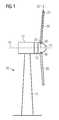
- a wind turbine 10is shown.
- the wind turbine 10comprises a nacelle 12 and a tower 11.
- the nacelle 12is mounted at the top of the tower 11.
- the nacelle 12is mounted rotatable with regard to the tower 11 by means of a yaw bearing.
- the axis of rotation of the nacelle 12 with regard to the tower 11is referred to as the yaw axis.
- the wind turbine 10also comprises a hub 13 with one or more rotor blades 20.
- the wind turbine 10comprises three rotor blades 20.
- the hub 13is mounted rotatable with regard to the nacelle 12 by means of a main bearing.
- the hub 13is mounted rotatable about a rotor axis of rotation 14.
- the wind turbine 10furthermore comprises a main shaft which connects the hub 13 with a rotor of a generator 15. If the hub 13 is connected directly to the rotor, the wind turbine is referred to as a gearless, direct drive wind turbine. Alternatively, the hub 13 may also be connected to the rotor via a gearbox. This type of wind turbine is commonly referred to as a geared wind turbine.
- the generator 15is accommodated within the nacelle 13. It comprises the rotor and a stator. The generator 15 is arranged and prepared for converting the rotational energy from the rotor into electrical energy.
- the wind turbine 10comprises three rotor blades 20 (of which two rotor blades 20 are depicted in Figure 1 ).
- the rotor blades 20are mounted rotatable with regard to the hub 13 by means of a pitch bearing 30.
- the rotor blades 20may thus be pitched in order to optimize their orientation with regard to the wind flow impinging on the wind turbine 10.
- the rotor blades 20each comprise a root section 22 and a tip section 21.
- the root sectionrefers to the part of the rotor blade 20 which is closest to the hub 13 and the pitch bearing 30.
- the tip section 21refers to the part of the rotor blade 20 which is furthest away from the root section 22.
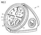
- a hub 13 of a wind turbineis depicted.
- the hub 13comprises three pitch bearings 30 of which one pitch bearing 30 is depicted.
- the hub 13comprises another large opening for the main bearing by which the hub is connected to the nacelle.
- the pitch bearing 30comprises an outer bearing ring 33 and an inner bearing ring 34. Both bearing rings 33, 34 are arranged coaxially to each other.
- the outer bearing ring 33is firmly interconnected to the hub 13 via a plurality of bolts (not shown).
- the inner bearing ring 34provides a plurality of holes (not shown) in which bolts for firmly interconnecting the inner bearing ring 34 with a root section of a rotor blade can be performed.
- the first reinforcement plate 31comprises the shape of a disk. It further comprises a plurality of openings 36 for providing an access between the inside of the hub 13 and the inside of the rotor blade 20 which is destined for being mounted to the pitch bearing 30. Note that the first reinforcement plate 31 comprises one opening 36 which is sufficiently large for allowing a service personal to climb through and access the inside of the rotor blade.
- Figure 2shows a specific embodiment of further means for reinforcing the pitch bearing 30.
- the further meanscomprise a first plate 401, a second plate 402, a third plate 403 and a fourth plate 404.
- the four platesare distributed equally on the surface of the first reinforcement plate 31. They have the shape of a plate and are orientated upright, i.e. in an angle of substantially 90 degrees with regard to the first reinforcement plate 31. Thusb a particularly solid and robust construction of the pitch bearing 30 is realized.
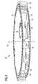
- a reinforced pitch bearing 30is shown in more detail.
- the sandwich-type configuration of the two reinforcement plates 31, 32can be well discerned. Both reinforcement plates 31, 32 are parallel to each other. It can be seen that the further means 40 are directly connected to both reinforcement plates 31, 32.
- the inner bearing ring 34comprises an upper surface at a first axial end and a lower surface at a second axial end, whereby the axial ends refer to the common axis of symmetry 35 of the two bearing rings 34, 33.
- the reinforcement plates 31, 32are flush with the outer surface of the inner bearing ring 34. In other words, the reinforcement plates 31, 32 fully cover the upper surface and the lower surface of the inner bearing ring 34, respectively.
- Figure 4shows the same embodiment of the reinforced pitch bearing as shown in Figure 3 without the inner bearing ring 34 and the outer bearing ring 33.
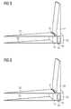
- Figure 5shows another embodiment of a reinforced pitch bearing.
- an inner bearing ring 34 and an outer bearing ring 33can be seen. Both bearing rings 33, 34 are arranged coaxially to each other.
- the pitch bearingis reinforced by a first reinforcement plate 31 and a second reinforcement plate 32.
- the pitch bearingis further reinforced by a stiffening block which serves as a further means 40 for reinforcing the pitch bearing.
- the further means 40is attached to the reinforcement plates 31, 32 by a plurality of equally distributed bolts 41.
- a part of a root section 22 of a rotor bladeis visualized. The root section 22 of the rotor blade is bolted to the inner bearing ring 34 by bolts 41 which traverse the second reinforcement plate 32, the inner bearing ring 34, and the first reinforcement plate 31.
- FIG 6another embodiment of a reinforced pitch bearing is illustrated. This embodiment is similar to the embodiment shown in Figure 5 .
- the further means 40 for reinforcing the pitch bearinghave a cross section that is similar to a C-shape. In other words, the further means 40 extend between the inner bearing ring 34 and the reinforcement plates 31, 32.
- the further meansare attached to the remaining pitch bearing by means of a plurality of bolts 41 whereby a first set of bolts connects the further means 40 with the two reinforcement plates 31, 32 and a second set of bolts 41 connects the inner bearing ring 34, the two reinforcement plates 31, 32 with the root section 22 of the rotor blade.
Landscapes
- Engineering & Computer Science (AREA)
- General Engineering & Computer Science (AREA)
- Mechanical Engineering (AREA)
- Life Sciences & Earth Sciences (AREA)
- Sustainable Development (AREA)
- Sustainable Energy (AREA)
- Chemical & Material Sciences (AREA)
- Combustion & Propulsion (AREA)
- Physics & Mathematics (AREA)
- Fluid Mechanics (AREA)
- Wind Motors (AREA)
Abstract
Description
- The invention relates to a pitch bearing of a wind turbine with an improved stiffness compared to existing pitch bearings of wind turbines. Furthermore, the invention relates to a wind turbine comprising such a pitch bearing. Finally, the invention relates to a method for reinforcing a pitch bearing of a wind turbine.
- Large, industrial type horizontal axis wind turbines typically comprise a pitch regulation for controlling the orientation of their rotor blades with regard to the incoming airflow of the wind. In comparison to a stall regulated wind turbine, where the rotor blades are rigidly fixed to the hub of the wind turbine, in pitch regulated wind turbines the rotor blades are pivotable mounted to the hub. This has the advantage that the orientation of the rotor blades with regard to the incoming airflow can be chosen such that the amount of generated electricity by the wind turbine is optimized.
- Typically, the rotor blades are mounted to the hub via a bearing comprising an inner bearing ring and an outer bearing ring. The bearing may be a roller bearing, for instance a tapered roller bearing.
- As wind turbines become larger and larger and consequently the rotor blades become larger and larger the forces which are transferred from the rotor blade to the hub via the pitch bearing increase as well. Thus, a reinforcement of the pitch bearing is advantageous.
- In order to reinforce the pitch bearing the European patent application
EP 2 045 464 A2 discloses a pair of reinforcing plates. These reinforcing plates are arranged such with regard to the inner bearing ring that they build a sandwich-type closed structure. - However, deformation of the pitch bearing, in particular of the inner bearing ring and/or of the outer bearing ring, may still occur if extreme forces are applied to the pitch bearing.
- Thus, it would be advantageous to provide a pitch bearing with a further improved stiffness.
- This objective is achieved by the independent claims. The dependent claims describe advantageous developments and modifications of the invention.
- In accordance with the invention there is provided a reinforced pitch bearing of a wind turbine comprising a first reinforcement plate and a second reinforcement plate. The pitch bearing comprises an outer bearing ring and an inner bearing ring, whereby both bearing rings are arranged coaxially to each other, thus comprising a common axis of symmetry. The first reinforcement plate is arranged at a first axial end of the pitch bearing and the second reinforcement plate is arranged at a second axial end of the pitch bearing. The axial ends are defined with regard to the common axis of symmetry. The reinforcement plates are arranged substantially parallel to each other and the pitch bearing comprises further means for reinforcement, whereby the further means are arranged in between the first reinforcement plate and the second reinforcement plate.
- A wind turbine refers to a device that can convert wind energy, i.e. kinetic energy from wind, into mechanical energy, which is subsequently used to generate electricity. A wind turbine is also denoted a wind power plant.
- A rotor blade of a wind turbine is also denoted a wind turbine rotor blade.
- The reinforcement plates have the shape of a plate, which means that their lateral extension is considerably larger than their thickness. As the outer bearing ring and the inner bearing ring both have preferably an annular shape, in a preferred embodiment the reinforcement plates have the shape of a circular cylinder. In other words, the cross section of the reinforcement plates in a top view of the pitch bearing is a circle.
- Advantageously, the reinforcement plates are configured and arranged such that their outer limit coincides with the outer limit of the inner bearing ring.
- The inner bearing ring and the outer bearing ring are arranged coaxially to each other. This means that the axis of rotational symmetry of the inner bearing ring and of the outer bearing ring coincides. Thus, both bearing rings have a common axis of symmetry. When a rotor blade is mounted to the hub of the wind turbine this common axis of symmetry of the pitch bearing coincides with an axis which is called the pitch axis of the rotor blade. The pitch axis of a rotor blade is commonly known as the axis about which the pitch regulation movement of the rotor blade is performed.
- A first axial end can be attributed to the pitch bearing defined by the end of the pitch bearing in axial direction whereby axial refers to the common axis of symmetry of the pitch bearing. Likewise, a second axial end can be attributed to the pitch bearing, being defined as a second end of the pitch bearing in axial direction, whereby the first axial end is opposite to the second axial end. As the first reinforcement plate is arranged at the first axial end of the pitch bearing and the second reinforcement plate is arranged at the second axial end of the pitch bearing, the whole configuration can be described as a sandwich-type configuration. In other words, the two reinforcement plates close the inner bearing ring, thus generating a hollow space surrounded by the inner surface of the inner bearing ring and the two reinforcement plates.
- The first reinforcement plate and the second reinforcement plate lead to a significant increase of the stiffness of the pitch bearing. However, deformation or other damage to the pitch bearing can still occur when high loads are applied to the wind turbine. A key aspect of the present invention is to introduce further means for reinforcement in the hollow space between the first reinforcement plate and the second reinforcement plate.
- The further means for reinforcing the pitch bearing may advantageously be of cast iron, steel, carbon fiber, Kevlar and/or a combination of these materials.
- Also note that different shapes differing from a shape of a plate are possible, too. Also note that alternative couplings of the further means and the reinforcement plates are possible, too.
- An advantage of a reinforced pitch bearing as described above is that large diameters of the pitch bearing are possible while still maintaining a high fatigue limit.
- Another advantage of the described reinforced pitch bearing is that the outer bearing ring and the inner bearing ring can be kept relatively thin, thus saving expensive material for the bearing rings, while the pitch bearing is reinforced by separate means which can be fabricated by separate material.
- In particular, the reduction in bending stress may improve the fatigue reserve factor of the bolts and thus reduce the overall stress in the blade bolts under extreme loading. Investigations with the reinforced pitch bearing comparing to a conventional pitch bearing have proven a reduction between 2% and 10% in the total stress of the blade bolt.
- Another advantage of coupling the two reinforcement plates via the further means is that if deformation of the pitch bearing under extreme loads occurs, the further means induce a reduced deformation of the sandwich-type reinforcement plates.
- In an advantageous embodiment, the first reinforcement plate and the second reinforcement plate are coupled by the further means for reinforcing the pitch bearing in such a way that the stiffness of the pitch bearing is increased.
- An advantage of coupling the further means with both reinforcement plates is that transfer of forces from one side of the pitch bearing to the other side is ensured. The connection between the further means and the reinforcement plates have to be carried out with care in order to ensure that the connection is sufficiently stable to withstand the loads acting on it. Note that wind turbines operate in harsh conditions during a lifetime exceeding 20 or even 25 years.
- In another advantageous embodiment, the first reinforcement plate and/or the second reinforcement plate are substantially perpendicular to the common axis of symmetry.
- As most relevant forces are acting in a direction substantially parallel to the common axis of symmetry of the pitch bearing, i.e. acting along the pitch axis, it is advantageous to place the reinforcement plates substantially perpendicular to the common axis of symmetry in order to maximize the resistance against deformation of the pitch bearing. When the reinforcement plates are attached to an upper surface and a lower surface of the inner bearing ring, it is thus advantageous if the inner bearing ring comprises an upper surface and a lower surface which is plane and which is substantially perpendicular to the common axis of symmetry.
- In another advantageous embodiment, the first reinforcement plate and/or the second reinforcement plate are attached to the inner bearing ring.
- Preferably, the reinforcement plates are attached to the inner bearing ring such that they fully cover the upper surface and the lower surface of the inner bearing ring. Thus, an optimal connection and an optimal transfer of forces between the inner bearing ring and the reinforcement plates are ensured.
- In another advantageous embodiment, each reinforcement plate comprises at least one opening to access the interior of a wind turbine rotor blade mounted to the pitch bearing.
- During assembling the wind turbine, in particular during mounting and attaching the wind turbine rotor blade to the hub it is advantageous if service personal has access to the inside of the wind turbine rotor blade. This may be realized by openings in the shell of the wind turbine rotor blade. However, in a particularly efficient and advantageous way this is realized by openings in both reinforcement plates. Thus, at least an access for machines or even for human beings is advantageous. For large pitch bearings, which may in practice easily exceed several meters in diameter, several openings in the reinforcement plates might be advantageous.
- In another advantageous embodiment, the further means for reinforcing the pitch bearing comprise at least one plate which is placed upright between the reinforcement plates.
- A further means for reinforcing the pitch bearing is particularly advantageous if it has the shape of a plate being placed upright between the reinforcement plates because thus an optimal increase of the stiffness is achieved. The shape of a plate is also advantageous because it combines a minimum weight and volume of the further means with the provision of high stiffness. A minimum volume of the further means is advantageous in that it minimizes the weight of the pitch bearing, the material needed to provide the further means and consequently the cost of the reinforced pitch bearing.
- Note that a placement upright between the reinforcement plates has to be understood that a plate comprising a lateral extension and a thickness is arranged such with regard to the reinforcement plates that the lateral extension of the further means is substantially perpendicular to the lateral extension of the reinforcement plates. This has the further advantage that a minimum lateral extension of the further means has to be provided. Compared, for instance, by an alternative arrangement where the further means are orientated with regard to the reinforcement plates in an angle, which is significantly different from 90 degrees.
- In another advantageous embodiment, the further means comprise at least two plates which are placed opposite to each other.
- It is advantageous to provide several plates in order to further improve the stiffness of the pitch bearing.
- It is furthermore advantageous to split the further means in several separate plates which leads to ease of manufacturing, ease of transportation of the further means and gives more flexibility of arranging the further means in between the space in between the two reinforcement plates.
- It is also possible to provide more than two plates between the reinforcement plates, for instance four plates. These four plates may for instance be arranged such that they divide the cross section comprising the shape of a disc in four equal parts or sections.
- In another advantageous embodiment, the further means for reinforcing the pitch bearing extend along an inner surface of the inner bearing ring.
- In other words, the further means may also have the shape of at least a part of a hollow circular cylinder. The further means may be understood or may be configured such that they represent a third annular object building the pitch bearing. In other words, the further means may represent a second inner bearing ring having an outer diameter which is just slightly smaller than the inner diameter of the inner bearing ring.
- Thus, in a preferred embodiment, the further means have an annular shape and are arranged coaxially with regard to the inner bearing ring.
- In another advantageous embodiment, the further means are bolted to the reinforcement plates.
- In principle, the further means can be connected to the reinforcement plates in various ways. As, however, it is advantageous to realize a stable and durable connection between the further means and the reinforcement plates a bolted connection is a preferred choice. Note, however, that in principle a connection which is realized by an adhesive or by pins or the like is possible, too.
- It may be advantageous to use bolts which traverse the first reinforcement plate, the further means for reinforcing the pitch bearing and the second reinforcement plate. Thus, a sufficiently long bolt is preferably provided.
- In another advantageous embodiment, the further means are bolted to the root of the wind turbine rotor blade.
- A wind turbine rotor blade in principle comprises a root and a root section, wherein the root section surrounds the root. In one alternative, the hub is attached and connected to the outer bearing ring and the rotor blade is connected to the inner bearing ring.
- In any case it may be advantageous that the further means are bolted to the root of the wind turbine rotor blade thus directly and firmly interconnecting these two parts.
- Exemplarily, the bolt traverses the further means and the first reinforcement plate and subsequently enters the root section of the wind turbine rotor blade. The described bolt connection which interconnects the root of the wind turbine rotor blade with the further means can be combined with the bolted connection between the further means and the reinforcement plates.
- This has the advantage of providing a particularly stable and durable connection.
- The invention is also directed towards a wind turbine comprising at least one wind turbine rotor blade, a hub and at least one pitch bearing according to one of the described embodiments, wherein the pitch bearing pivotably connects the wind turbine rotor blade with the hub.
- Advantageously, all wind turbine rotor blades of the wind turbine are equipped with such a reinforced pitch bearing. This has the advantage that forces and fatigue limits are equally distributed with regard to the considered wind turbine rotor blades comprised by the wind turbine.
- Furthermore, the invention is directed towards a method for reinforcing a pitch bearing of a wind turbine, wherein the pitch bearing comprises an outer bearing ring and an inner bearing ring, whereby both bearing rings are arranged coaxially to each other thus comprising a common axis of symmetry.
- The method comprises the following steps:
- attaching a first reinforcement plate to a first axial end of the pitch bearing and a second reinforcement plate to a second axial end of the pitch bearing, whereby the axial ends are defined with regard to the common axis of symmetry and the reinforcement plates are arranged substantially parallel to each other, and
- attaching further means for reinforcing the pitch bearing in between the first reinforcement plate and the second reinforcement plate.
- The order of the different attachment steps can be performed in various ways. It may be advantageous to firstly attach the first reinforcement plate to the inner bearing ring, for instance, subsequently attach the further means to the first reinforcement plate and finally attach the second reinforcement plate to the further means and the inner bearing ring.
- Alternatively, it may also be advantageous to first attach both reinforcement plates to the remaining part of the pitch bearing and subsequently introduce and connect the further means. This may be done via one or more openings of the reinforcement plates.
- Embodiments of the invention are now described, by way of example only, with reference to the accompanying drawings, of which:
- Figure 1
- shows a wind turbine with pitch regulated wind turbine rotor blades;
- Figure 2
- shows a hub of a wind turbine with a reinforced pitch bearing;
- Figure 3
- shows a reinforced pitch bearing comprising four reinforcement plates arranged upright in between the first reinforcement plate and a second reinforcement plate;
- Figure 4
- shows a detailed view of
Figure 3 without the bearing rings; - Figure 5
- shows a further means for reinforcing the pitch bearing having an annular shape; and
- Figure 6
- shows a further means for reinforcing a pitch bearing having the shape of a C.
- The illustration in the drawings is in schematic form. It is noted that in different figures, similar or identical elements may be provided with the same reference signs.
- In
Figure 1 , awind turbine 10 is shown. Thewind turbine 10 comprises anacelle 12 and atower 11. Thenacelle 12 is mounted at the top of thetower 11. Thenacelle 12 is mounted rotatable with regard to thetower 11 by means of a yaw bearing. The axis of rotation of thenacelle 12 with regard to thetower 11 is referred to as the yaw axis. - The
wind turbine 10 also comprises ahub 13 with one ormore rotor blades 20. Preferably, thewind turbine 10 comprises threerotor blades 20. Thehub 13 is mounted rotatable with regard to thenacelle 12 by means of a main bearing. Thehub 13 is mounted rotatable about a rotor axis ofrotation 14. - The
wind turbine 10 furthermore comprises a main shaft which connects thehub 13 with a rotor of agenerator 15. If thehub 13 is connected directly to the rotor, the wind turbine is referred to as a gearless, direct drive wind turbine. Alternatively, thehub 13 may also be connected to the rotor via a gearbox. This type of wind turbine is commonly referred to as a geared wind turbine. - The
generator 15 is accommodated within thenacelle 13. It comprises the rotor and a stator. Thegenerator 15 is arranged and prepared for converting the rotational energy from the rotor into electrical energy. - In the concrete example of
Figure 1 , thewind turbine 10 comprises three rotor blades 20 (of which tworotor blades 20 are depicted inFigure 1 ). Therotor blades 20 are mounted rotatable with regard to thehub 13 by means of apitch bearing 30. Therotor blades 20 may thus be pitched in order to optimize their orientation with regard to the wind flow impinging on thewind turbine 10. - Furthermore note that the
rotor blades 20 each comprise aroot section 22 and atip section 21. The root section refers to the part of therotor blade 20 which is closest to thehub 13 and thepitch bearing 30. Thetip section 21 refers to the part of therotor blade 20 which is furthest away from theroot section 22. - In
Figure 2 , ahub 13 of a wind turbine is depicted. Thehub 13 comprises threepitch bearings 30 of which onepitch bearing 30 is depicted. Furthermore, thehub 13 comprises another large opening for the main bearing by which the hub is connected to the nacelle. - As can be seen, the pitch bearing 30 comprises an
outer bearing ring 33 and aninner bearing ring 34. Both bearing rings 33, 34 are arranged coaxially to each other. Theouter bearing ring 33 is firmly interconnected to thehub 13 via a plurality of bolts (not shown). Likewise, theinner bearing ring 34 provides a plurality of holes (not shown) in which bolts for firmly interconnecting theinner bearing ring 34 with a root section of a rotor blade can be performed. - At the end of the pitch bearing 30 which faces the inside of the hub 13 a
first reinforcement plate 31 is attached. Thefirst reinforcement plate 31 comprises the shape of a disk. It further comprises a plurality ofopenings 36 for providing an access between the inside of thehub 13 and the inside of therotor blade 20 which is destined for being mounted to thepitch bearing 30. Note that thefirst reinforcement plate 31 comprises oneopening 36 which is sufficiently large for allowing a service personal to climb through and access the inside of the rotor blade. Figure 2 shows a specific embodiment of further means for reinforcing thepitch bearing 30. The further means comprise afirst plate 401, asecond plate 402, athird plate 403 and afourth plate 404.- The four plates are distributed equally on the surface of the
first reinforcement plate 31. They have the shape of a plate and are orientated upright, i.e. in an angle of substantially 90 degrees with regard to thefirst reinforcement plate 31. Thusb a particularly solid and robust construction of the pitch bearing 30 is realized. - In
Figure 3 , a reinforced pitch bearing 30 is shown in more detail. The sandwich-type configuration of the tworeinforcement plates reinforcement plates reinforcement plates inner bearing ring 34 comprises an upper surface at a first axial end and a lower surface at a second axial end, whereby the axial ends refer to the common axis ofsymmetry 35 of the two bearing rings 34, 33. Thereinforcement plates inner bearing ring 34. In other words, thereinforcement plates inner bearing ring 34, respectively. Figure 4 shows the same embodiment of the reinforced pitch bearing as shown inFigure 3 without theinner bearing ring 34 and theouter bearing ring 33.Figure 5 shows another embodiment of a reinforced pitch bearing. Again, aninner bearing ring 34 and anouter bearing ring 33 can be seen. Both bearing rings 33, 34 are arranged coaxially to each other. The pitch bearing is reinforced by afirst reinforcement plate 31 and asecond reinforcement plate 32. The pitch bearing is further reinforced by a stiffening block which serves as a further means 40 for reinforcing the pitch bearing. The further means 40 is attached to thereinforcement plates bolts 41. Finally a part of aroot section 22 of a rotor blade is visualized. Theroot section 22 of the rotor blade is bolted to theinner bearing ring 34 bybolts 41 which traverse thesecond reinforcement plate 32, theinner bearing ring 34, and thefirst reinforcement plate 31.- In
Figure 6 another embodiment of a reinforced pitch bearing is illustrated. This embodiment is similar to the embodiment shown inFigure 5 . However, in the embodiment ofFigure 6 the further means 40 for reinforcing the pitch bearing have a cross section that is similar to a C-shape. In other words, the further means 40 extend between theinner bearing ring 34 and thereinforcement plates - This has the advantage that it further improves the stiffness of the pitch bearing. Again the further means are attached to the remaining pitch bearing by means of a plurality of
bolts 41 whereby a first set of bolts connects the further means 40 with the tworeinforcement plates bolts 41 connects theinner bearing ring 34, the tworeinforcement plates root section 22 of the rotor blade. - Although the present invention has been described in detail with reference to preferred embodiments, it is to be understood that the present invention is not limited by the disclosed examples. In fact, numerous additional modifications and variations could be made thereto by a person skilled in the art without departing from the scope of the invention.
- It should also be noted that the use of "a" or "an" throughout this application does not exclude a plurality, and "comprising" does not exclude other steps or elements. Also elements described in association with different embodiments may be combined. It should furthermore be noted that reference signs in the claims should be construed as limiting the scope of the claims.
Claims (13)
- Reinforced pitch bearing (30) of a wind turbine (10) comprising a first reinforcement plate (31) and a second reinforcement plate (32), wherein- the pitch bearing (30) comprises an outer bearing ring (33) and an inner bearing ring (34), whereby both bearing rings (33, 34) are arranged coaxially to each other, thus comprising a common axis of symmetry (35),- the first reinforcement plate (31) is arranged at a first axial end of the pitch bearing (30) and the second reinforcement plate (32) is arranged at a second axial end of the pitch bearing (30), the axial ends being defined with regard to the common axis of symmetry (35),- the reinforcement plates (31, 32) are arranged substantially parallel to each other, and- the pitch bearing (30) comprises further means (40) for reinforcement, the further means (40) being arranged in between the first reinforcement plate (31) and the second reinforcement plate (32).
- Pitch bearing according to claim 1,
wherein both reinforcement plates (31, 32) are coupled by the further means (40) for reinforcing the pitch bearing (30) such that the stiffness of the pitch bearing (30) is increased. - Pitch bearing according to one of the preceding claims,
wherein the first reinforcement plate (31) and/or the second reinforcement plate (32) are substantially perpendicular to the common axis of symmetry (35). - Pitch bearing according to one of the preceding claims,
wherein the first reinforcement plate (31) and/or the second reinforcement plate (32) are attached to the inner bearing ring (34). - Pitch bearing according to one of the preceding claims,
wherein each reinforcement plate (31, 32) comprises at least one opening (36) to access the interior of a rotor blade (20) of the wind turbine (10) mounted to the pitch bearing (30). - Pitch bearing according to one of the preceding claims,
wherein the further means (40) for reinforcing the pitch bearing (30) comprise at least one plate which is placed upright between the reinforcement plates (31, 32). - Pitch bearing according to one of the preceding claims,
wherein the further means (40) comprise at least two plates which are placed opposite to each other. - Pitch bearing according to one of the preceding claims,
wherein the further means (40) for reinforcing the pitch bearing (30) extend along an inner surface of the inner bearing ring (341). - Pitch bearing according to one of the preceding claims,
wherein the further means (40) have an annular shape and are arranged coaxially with regard to the inner bearing ring (34). - Pitch bearing according to one of the preceding claims,
wherein the further means (40) are bolted to the reinforcement plates (31, 32). - Pitch bearing according to one of the preceding claims,
wherein the further means (40) are bolted to the root (22) of a rotor blade (20) of the wind turbine (10). - Wind turbine comprising at least one rotor blade (20), a hub (13) and at least one pitch bearing (30) according to one of the preceding claims,
wherein the pitch bearing (30) pivotably connects the rotor blade (20) with the hub (13). - Method for reinforcing a pitch bearing (30) of a wind turbine (10),
wherein the pitch bearing (30) comprises an outer bearing ring (33) and an inner bearing ring (34), whereby both bearing rings (33, 34) are arranged coaxially to each other, thus comprising a common axis of symmetry (35), and wherein the method comprises the steps of- attaching a first reinforcement plate (31) to a first axial end of the pitch bearing (30) and a second reinforcement plate (32) to a second axial end of the pitch bearing (30), whereby the axial ends are defined with regard to the common axis of symmetry (35) and the reinforcement plates (31, 32) are arranged substantially parallel to each other, and- attaching further means (40) for reinforcing the pitch bearing (30) in between the first reinforcement plate (31) and the second reinforcement plate (32).
Priority Applications (4)
| Application Number | Priority Date | Filing Date | Title |
|---|---|---|---|
| DK14165184.4TDK2933476T3 (en) | 2014-04-17 | 2014-04-17 | Reinforced pitch bearing of a wind turbine |
| EP14165184.4AEP2933476B1 (en) | 2014-04-17 | 2014-04-17 | Reinforced pitch bearing of a wind turbine |
| US14/679,129US9915245B2 (en) | 2014-04-17 | 2015-04-06 | Reinforced pitch bearing of a wind turbine |
| CN201510182995.2ACN105041872B (en) | 2014-04-17 | 2015-04-17 | Enhanced pitch bearings for wind turbines |
Applications Claiming Priority (1)
| Application Number | Priority Date | Filing Date | Title |
|---|---|---|---|
| EP14165184.4AEP2933476B1 (en) | 2014-04-17 | 2014-04-17 | Reinforced pitch bearing of a wind turbine |
Publications (2)
| Publication Number | Publication Date |
|---|---|
| EP2933476A1true EP2933476A1 (en) | 2015-10-21 |
| EP2933476B1 EP2933476B1 (en) | 2017-03-08 |
Family
ID=50549003
Family Applications (1)
| Application Number | Title | Priority Date | Filing Date |
|---|---|---|---|
| EP14165184.4AActiveEP2933476B1 (en) | 2014-04-17 | 2014-04-17 | Reinforced pitch bearing of a wind turbine |
Country Status (4)
| Country | Link |
|---|---|
| US (1) | US9915245B2 (en) |
| EP (1) | EP2933476B1 (en) |
| CN (1) | CN105041872B (en) |
| DK (1) | DK2933476T3 (en) |
Cited By (6)
| Publication number | Priority date | Publication date | Assignee | Title |
|---|---|---|---|---|
| EP3379077A1 (en) | 2017-03-21 | 2018-09-26 | Nordex Energy GmbH | Rotary joint of a wind power plant and toothing for a rotary joint |
| DE102017206246A1 (en) | 2017-04-11 | 2018-10-11 | Thyssenkrupp Ag | Bearing arrangement for mounting a rotor blade of a wind turbine |
| EP3653870A1 (en) | 2018-11-13 | 2020-05-20 | Siemens Gamesa Renewable Energy A/S | Pitch bearing arrangement |
| EP3141747B1 (en)* | 2015-09-08 | 2020-09-02 | Siemens Gamesa Renewable Energy A/S | Reinforced bearing of a wind turbine |
| EP3736438A1 (en)* | 2019-05-10 | 2020-11-11 | General Electric Company | Rotor assembly having a pitch bearing with a stiffener ring |
| EP4290070A1 (en) | 2022-06-08 | 2023-12-13 | Siemens Gamesa Renewable Energy A/S | Pitch bearing comprising a cover plate |
Families Citing this family (6)
| Publication number | Priority date | Publication date | Assignee | Title |
|---|---|---|---|---|
| CN110177932B (en)* | 2017-01-19 | 2021-06-29 | 西门子歌美飒可再生能源公司 | Blade Mounting Device |
| CN106930908B (en)* | 2017-05-23 | 2023-05-05 | 北京三力新能科技有限公司 | Variable-pitch bearing assembly |
| DE102018131321A1 (en)* | 2018-12-07 | 2020-06-10 | Wobben Properties Gmbh | Wind turbine with support structure |
| EP3845760A1 (en) | 2019-12-31 | 2021-07-07 | Nordex Energy Spain, S.A.U. | Pitch bearing of a wind turbine, wind turbine and method of limiting the stresses in the reinforcement plates of a pitch bearing |
| DK4043743T3 (en)* | 2021-02-12 | 2023-11-20 | Siemens Gamesa Renewable Energy As | BEARING FOR A WINDMILL, WINDMILL COMPRISING A BEARING, AND METHOD OF MAKING A BEARING |
| CN114483488A (en)* | 2022-01-14 | 2022-05-13 | 中车山东风电有限公司 | A kind of wind turbine blade switching device and manufacturing method |
Citations (6)
| Publication number | Priority date | Publication date | Assignee | Title |
|---|---|---|---|---|
| EP2045464A2 (en) | 2007-10-01 | 2009-04-08 | Siemens Aktiengesellschaft | Pitch bearing for wind turbine rotor blades |
| US20090311104A1 (en)* | 2006-11-13 | 2009-12-17 | Ulrik Steffensen | Reinforced bearing for a wind-power generator blade |
| US20110142618A1 (en)* | 2010-10-29 | 2011-06-16 | Bradley Graham Moore | Wind turbine pitch assembly enclosure system |
| EP2511521A1 (en)* | 2011-04-14 | 2012-10-17 | Siemens Aktiengesellschaft | Pitch bearing |
| EP2570655A1 (en)* | 2011-09-16 | 2013-03-20 | IMO Holding GmbH | Small-scale wind energy assembly and device for active adjustment of a blade for same |
| WO2013107452A1 (en)* | 2012-01-20 | 2013-07-25 | Vestas Wind Systems A/S | Blade bearing with support structure having non-uniform stiffness and method manufacture |
Family Cites Families (12)
| Publication number | Priority date | Publication date | Assignee | Title |
|---|---|---|---|---|
| US3774982A (en)* | 1971-12-02 | 1973-11-27 | Hitachi Ltd | Bearing device for rotary machines |
| DK1311759T3 (en)* | 2000-08-15 | 2013-01-07 | Zf Wind Power Antwerpen Nv | Wind turbine turbine system |
| WO2007003866A1 (en) | 2005-07-05 | 2007-01-11 | Vestas Wind Systems A/S | A wind turbine pitch bearing, and use hereof |
| EP1925860A1 (en)* | 2006-11-02 | 2008-05-28 | Ecotecnia Energias Renovables S.L. | Device for fitting a seal |
| CN201730757U (en)* | 2010-04-16 | 2011-02-02 | 辽宁中科天道新能源装备工业有限公司 | Hub structure for wind generator set |
| EP2546512B1 (en)* | 2011-07-13 | 2016-03-02 | ALSTOM Renewable Technologies | Wind turbine rotor |
| EP2630368B1 (en)* | 2011-11-22 | 2014-12-31 | Mitsubishi Heavy Industries, Ltd. | Wind turbine |
| CN202326046U (en)* | 2011-12-08 | 2012-07-11 | 华锐风电科技(集团)股份有限公司 | Hub for wind generating set |
| EP2623772A1 (en)* | 2012-02-06 | 2013-08-07 | Alstom Wind, S.L.U. | Wind turbine rotor |
| US9353729B2 (en)* | 2013-07-02 | 2016-05-31 | General Electric Company | Aerodynamic hub assembly for a wind turbine |
| US9523348B2 (en)* | 2013-09-25 | 2016-12-20 | General Electric Company | Rotor blade assembly with shim plate for mitigation pitch bearing loads |
| US9970414B2 (en)* | 2015-07-01 | 2018-05-15 | General Electric Company | Pitch assembly for a wind turbine rotor blade |
- 2014
- 2014-04-17EPEP14165184.4Apatent/EP2933476B1/enactiveActive
- 2014-04-17DKDK14165184.4Tpatent/DK2933476T3/enactive
- 2015
- 2015-04-06USUS14/679,129patent/US9915245B2/enactiveActive
- 2015-04-17CNCN201510182995.2Apatent/CN105041872B/enactiveActive
Patent Citations (6)
| Publication number | Priority date | Publication date | Assignee | Title |
|---|---|---|---|---|
| US20090311104A1 (en)* | 2006-11-13 | 2009-12-17 | Ulrik Steffensen | Reinforced bearing for a wind-power generator blade |
| EP2045464A2 (en) | 2007-10-01 | 2009-04-08 | Siemens Aktiengesellschaft | Pitch bearing for wind turbine rotor blades |
| US20110142618A1 (en)* | 2010-10-29 | 2011-06-16 | Bradley Graham Moore | Wind turbine pitch assembly enclosure system |
| EP2511521A1 (en)* | 2011-04-14 | 2012-10-17 | Siemens Aktiengesellschaft | Pitch bearing |
| EP2570655A1 (en)* | 2011-09-16 | 2013-03-20 | IMO Holding GmbH | Small-scale wind energy assembly and device for active adjustment of a blade for same |
| WO2013107452A1 (en)* | 2012-01-20 | 2013-07-25 | Vestas Wind Systems A/S | Blade bearing with support structure having non-uniform stiffness and method manufacture |
Cited By (8)
| Publication number | Priority date | Publication date | Assignee | Title |
|---|---|---|---|---|
| EP3141747B1 (en)* | 2015-09-08 | 2020-09-02 | Siemens Gamesa Renewable Energy A/S | Reinforced bearing of a wind turbine |
| EP3379077A1 (en) | 2017-03-21 | 2018-09-26 | Nordex Energy GmbH | Rotary joint of a wind power plant and toothing for a rotary joint |
| DE102017206246A1 (en) | 2017-04-11 | 2018-10-11 | Thyssenkrupp Ag | Bearing arrangement for mounting a rotor blade of a wind turbine |
| WO2018189143A1 (en) | 2017-04-11 | 2018-10-18 | Thyssenkrupp Rothe Erde Gmbh | Bearing arrangement for mounting a rotor blade of a wind turbine |
| EP3653870A1 (en) | 2018-11-13 | 2020-05-20 | Siemens Gamesa Renewable Energy A/S | Pitch bearing arrangement |
| EP3736438A1 (en)* | 2019-05-10 | 2020-11-11 | General Electric Company | Rotor assembly having a pitch bearing with a stiffener ring |
| US11454219B2 (en) | 2019-05-10 | 2022-09-27 | General Electric Company | Rotor assembly having a pitch bearing with a stiffener ring |
| EP4290070A1 (en) | 2022-06-08 | 2023-12-13 | Siemens Gamesa Renewable Energy A/S | Pitch bearing comprising a cover plate |
Also Published As
| Publication number | Publication date |
|---|---|
| US9915245B2 (en) | 2018-03-13 |
| DK2933476T3 (en) | 2017-05-15 |
| EP2933476B1 (en) | 2017-03-08 |
| CN105041872B (en) | 2019-06-14 |
| US20150300322A1 (en) | 2015-10-22 |
| CN105041872A (en) | 2015-11-11 |
Similar Documents
| Publication | Publication Date | Title |
|---|---|---|
| EP2933476B1 (en) | Reinforced pitch bearing of a wind turbine | |
| US8465256B2 (en) | Wind turbine rotor | |
| EP2045464B2 (en) | Pitch bearing for wind turbine rotor blades | |
| US7857599B2 (en) | Method and apparatus for forming wind turbine machines | |
| DK2795108T3 (en) | Wind turbine Nacelle | |
| EP2383466A2 (en) | Wind turbine with integrated design and controlling method | |
| DK2917568T3 (en) | Wind turbine blade with fasteners | |
| CN101105173A (en) | Apparatus for assembling rotary machines | |
| US20140314580A1 (en) | Wind turbine | |
| EP3653870B1 (en) | Pitch bearing arrangement | |
| WO2015032803A1 (en) | Wind turbine | |
| US11761419B2 (en) | Root assembly of a wind turbine blade for a wind turbine, wind turbine blade and wind turbine | |
| EP3141747B1 (en) | Reinforced bearing of a wind turbine | |
| EP2975262B1 (en) | Wind power generation facility | |
| WO2011056121A1 (en) | Wind turbine with turbine blades | |
| EP3267032B1 (en) | Blade bearing arrangement for a wind turbine | |
| WO2024120599A1 (en) | Repowered wind turbine | |
| EP2981713B1 (en) | A hub and bearing system and a turbine comprising the hub and bearing system |
Legal Events
| Date | Code | Title | Description |
|---|---|---|---|
| PUAI | Public reference made under article 153(3) epc to a published international application that has entered the european phase | Free format text:ORIGINAL CODE: 0009012 | |
| 17P | Request for examination filed | Effective date:20150407 | |
| AK | Designated contracting states | Kind code of ref document:A1 Designated state(s):AL AT BE BG CH CY CZ DE DK EE ES FI FR GB GR HR HU IE IS IT LI LT LU LV MC MK MT NL NO PL PT RO RS SE SI SK SM TR | |
| AX | Request for extension of the european patent | Extension state:BA ME | |
| REG | Reference to a national code | Ref country code:DE Ref legal event code:R079 Ref document number:602014007291 Country of ref document:DE Free format text:PREVIOUS MAIN CLASS: F03D0007020000 Ipc:F03D0080000000 | |
| GRAP | Despatch of communication of intention to grant a patent | Free format text:ORIGINAL CODE: EPIDOSNIGR1 | |
| INTG | Intention to grant announced | Effective date:20160923 | |
| RIC1 | Information provided on ipc code assigned before grant | Ipc:F03D 80/00 20160101AFI20160915BHEP Ipc:F16C 33/58 20060101ALI20160915BHEP Ipc:F16C 43/04 20060101ALI20160915BHEP Ipc:F03D 80/70 20160101ALI20160915BHEP Ipc:F03D 7/02 20060101ALI20160915BHEP | |
| GRAS | Grant fee paid | Free format text:ORIGINAL CODE: EPIDOSNIGR3 | |
| GRAA | (expected) grant | Free format text:ORIGINAL CODE: 0009210 | |
| AK | Designated contracting states | Kind code of ref document:B1 Designated state(s):AL AT BE BG CH CY CZ DE DK EE ES FI FR GB GR HR HU IE IS IT LI LT LU LV MC MK MT NL NO PL PT RO RS SE SI SK SM TR | |
| REG | Reference to a national code | Ref country code:GB Ref legal event code:FG4D | |
| REG | Reference to a national code | Ref country code:CH Ref legal event code:EP Ref country code:AT Ref legal event code:REF Ref document number:873775 Country of ref document:AT Kind code of ref document:T Effective date:20170315 | |
| REG | Reference to a national code | Ref country code:IE Ref legal event code:FG4D | |
| REG | Reference to a national code | Ref country code:DE Ref legal event code:R096 Ref document number:602014007291 Country of ref document:DE | |
| REG | Reference to a national code | Ref country code:FR Ref legal event code:PLFP Year of fee payment:4 | |
| REG | Reference to a national code | Ref country code:DK Ref legal event code:T3 Effective date:20170511 | |
| REG | Reference to a national code | Ref country code:LT Ref legal event code:MG4D | |
| REG | Reference to a national code | Ref country code:NL Ref legal event code:MP Effective date:20170308 | |
| PG25 | Lapsed in a contracting state [announced via postgrant information from national office to epo] | Ref country code:LT Free format text:LAPSE BECAUSE OF FAILURE TO SUBMIT A TRANSLATION OF THE DESCRIPTION OR TO PAY THE FEE WITHIN THE PRESCRIBED TIME-LIMIT Effective date:20170308 Ref country code:GR Free format text:LAPSE BECAUSE OF FAILURE TO SUBMIT A TRANSLATION OF THE DESCRIPTION OR TO PAY THE FEE WITHIN THE PRESCRIBED TIME-LIMIT Effective date:20170609 Ref country code:NO Free format text:LAPSE BECAUSE OF FAILURE TO SUBMIT A TRANSLATION OF THE DESCRIPTION OR TO PAY THE FEE WITHIN THE PRESCRIBED TIME-LIMIT Effective date:20170608 Ref country code:HR Free format text:LAPSE BECAUSE OF FAILURE TO SUBMIT A TRANSLATION OF THE DESCRIPTION OR TO PAY THE FEE WITHIN THE PRESCRIBED TIME-LIMIT Effective date:20170308 Ref country code:FI Free format text:LAPSE BECAUSE OF FAILURE TO SUBMIT A TRANSLATION OF THE DESCRIPTION OR TO PAY THE FEE WITHIN THE PRESCRIBED TIME-LIMIT Effective date:20170308 | |
| REG | Reference to a national code | Ref country code:AT Ref legal event code:MK05 Ref document number:873775 Country of ref document:AT Kind code of ref document:T Effective date:20170308 | |
| RAP2 | Party data changed (patent owner data changed or rights of a patent transferred) | Owner name:SIEMENS AKTIENGESELLSCHAFT | |
| PG25 | Lapsed in a contracting state [announced via postgrant information from national office to epo] | Ref country code:LV Free format text:LAPSE BECAUSE OF FAILURE TO SUBMIT A TRANSLATION OF THE DESCRIPTION OR TO PAY THE FEE WITHIN THE PRESCRIBED TIME-LIMIT Effective date:20170308 Ref country code:BG Free format text:LAPSE BECAUSE OF FAILURE TO SUBMIT A TRANSLATION OF THE DESCRIPTION OR TO PAY THE FEE WITHIN THE PRESCRIBED TIME-LIMIT Effective date:20170608 Ref country code:SE Free format text:LAPSE BECAUSE OF FAILURE TO SUBMIT A TRANSLATION OF THE DESCRIPTION OR TO PAY THE FEE WITHIN THE PRESCRIBED TIME-LIMIT Effective date:20170308 Ref country code:RS Free format text:LAPSE BECAUSE OF FAILURE TO SUBMIT A TRANSLATION OF THE DESCRIPTION OR TO PAY THE FEE WITHIN THE PRESCRIBED TIME-LIMIT Effective date:20170308 Ref country code:ES Free format text:LAPSE BECAUSE OF FAILURE TO SUBMIT A TRANSLATION OF THE DESCRIPTION OR TO PAY THE FEE WITHIN THE PRESCRIBED TIME-LIMIT Effective date:20170308 | |
| PG25 | Lapsed in a contracting state [announced via postgrant information from national office to epo] | Ref country code:NL Free format text:LAPSE BECAUSE OF FAILURE TO SUBMIT A TRANSLATION OF THE DESCRIPTION OR TO PAY THE FEE WITHIN THE PRESCRIBED TIME-LIMIT Effective date:20170308 | |
| REG | Reference to a national code | Ref country code:CH Ref legal event code:NV Representative=s name:SIEMENS SCHWEIZ AG, CH Ref country code:CH Ref legal event code:PCOW Free format text:NEW ADDRESS: WERNER-VON-SIEMENS-STRASSE 1, 80333 MUENCHEN (DE) | |
| PG25 | Lapsed in a contracting state [announced via postgrant information from national office to epo] | Ref country code:SK Free format text:LAPSE BECAUSE OF FAILURE TO SUBMIT A TRANSLATION OF THE DESCRIPTION OR TO PAY THE FEE WITHIN THE PRESCRIBED TIME-LIMIT Effective date:20170308 Ref country code:CZ Free format text:LAPSE BECAUSE OF FAILURE TO SUBMIT A TRANSLATION OF THE DESCRIPTION OR TO PAY THE FEE WITHIN THE PRESCRIBED TIME-LIMIT Effective date:20170308 Ref country code:IT Free format text:LAPSE BECAUSE OF FAILURE TO SUBMIT A TRANSLATION OF THE DESCRIPTION OR TO PAY THE FEE WITHIN THE PRESCRIBED TIME-LIMIT Effective date:20170308 Ref country code:AT Free format text:LAPSE BECAUSE OF FAILURE TO SUBMIT A TRANSLATION OF THE DESCRIPTION OR TO PAY THE FEE WITHIN THE PRESCRIBED TIME-LIMIT Effective date:20170308 Ref country code:RO Free format text:LAPSE BECAUSE OF FAILURE TO SUBMIT A TRANSLATION OF THE DESCRIPTION OR TO PAY THE FEE WITHIN THE PRESCRIBED TIME-LIMIT Effective date:20170308 Ref country code:EE Free format text:LAPSE BECAUSE OF FAILURE TO SUBMIT A TRANSLATION OF THE DESCRIPTION OR TO PAY THE FEE WITHIN THE PRESCRIBED TIME-LIMIT Effective date:20170308 | |
| PG25 | Lapsed in a contracting state [announced via postgrant information from national office to epo] | Ref country code:SM Free format text:LAPSE BECAUSE OF FAILURE TO SUBMIT A TRANSLATION OF THE DESCRIPTION OR TO PAY THE FEE WITHIN THE PRESCRIBED TIME-LIMIT Effective date:20170308 Ref country code:IS Free format text:LAPSE BECAUSE OF FAILURE TO SUBMIT A TRANSLATION OF THE DESCRIPTION OR TO PAY THE FEE WITHIN THE PRESCRIBED TIME-LIMIT Effective date:20170708 Ref country code:PL Free format text:LAPSE BECAUSE OF FAILURE TO SUBMIT A TRANSLATION OF THE DESCRIPTION OR TO PAY THE FEE WITHIN THE PRESCRIBED TIME-LIMIT Effective date:20170308 Ref country code:PT Free format text:LAPSE BECAUSE OF FAILURE TO SUBMIT A TRANSLATION OF THE DESCRIPTION OR TO PAY THE FEE WITHIN THE PRESCRIBED TIME-LIMIT Effective date:20170710 | |
| REG | Reference to a national code | Ref country code:CH Ref legal event code:PL | |
| REG | Reference to a national code | Ref country code:DE Ref legal event code:R097 Ref document number:602014007291 Country of ref document:DE | |
| PLBE | No opposition filed within time limit | Free format text:ORIGINAL CODE: 0009261 | |
| STAA | Information on the status of an ep patent application or granted ep patent | Free format text:STATUS: NO OPPOSITION FILED WITHIN TIME LIMIT | |
| REG | Reference to a national code | Ref country code:IE Ref legal event code:MM4A | |
| PG25 | Lapsed in a contracting state [announced via postgrant information from national office to epo] | Ref country code:MC Free format text:LAPSE BECAUSE OF FAILURE TO SUBMIT A TRANSLATION OF THE DESCRIPTION OR TO PAY THE FEE WITHIN THE PRESCRIBED TIME-LIMIT Effective date:20170308 | |
| 26N | No opposition filed | Effective date:20171211 | |
| PG25 | Lapsed in a contracting state [announced via postgrant information from national office to epo] | Ref country code:LI Free format text:LAPSE BECAUSE OF NON-PAYMENT OF DUE FEES Effective date:20170430 Ref country code:LU Free format text:LAPSE BECAUSE OF NON-PAYMENT OF DUE FEES Effective date:20170417 Ref country code:CH Free format text:LAPSE BECAUSE OF NON-PAYMENT OF DUE FEES Effective date:20170430 Ref country code:SI Free format text:LAPSE BECAUSE OF FAILURE TO SUBMIT A TRANSLATION OF THE DESCRIPTION OR TO PAY THE FEE WITHIN THE PRESCRIBED TIME-LIMIT Effective date:20170308 | |
| REG | Reference to a national code | Ref country code:BE Ref legal event code:MM Effective date:20170430 | |
| REG | Reference to a national code | Ref country code:FR Ref legal event code:PLFP Year of fee payment:5 | |
| PG25 | Lapsed in a contracting state [announced via postgrant information from national office to epo] | Ref country code:IE Free format text:LAPSE BECAUSE OF NON-PAYMENT OF DUE FEES Effective date:20170417 | |
| PG25 | Lapsed in a contracting state [announced via postgrant information from national office to epo] | Ref country code:BE Free format text:LAPSE BECAUSE OF NON-PAYMENT OF DUE FEES Effective date:20170430 | |
| PG25 | Lapsed in a contracting state [announced via postgrant information from national office to epo] | Ref country code:MT Free format text:LAPSE BECAUSE OF NON-PAYMENT OF DUE FEES Effective date:20170417 | |
| PG25 | Lapsed in a contracting state [announced via postgrant information from national office to epo] | Ref country code:HU Free format text:LAPSE BECAUSE OF FAILURE TO SUBMIT A TRANSLATION OF THE DESCRIPTION OR TO PAY THE FEE WITHIN THE PRESCRIBED TIME-LIMIT; INVALID AB INITIO Effective date:20140417 | |
| REG | Reference to a national code | Ref country code:DE Ref legal event code:R081 Ref document number:602014007291 Country of ref document:DE Owner name:SIEMENS GAMESA RENEWABLE ENERGY A/S, DK Free format text:FORMER OWNER: SIEMENS AKTIENGESELLSCHAFT, 80333 MUENCHEN, DE | |
| PG25 | Lapsed in a contracting state [announced via postgrant information from national office to epo] | Ref country code:CY Free format text:LAPSE BECAUSE OF FAILURE TO SUBMIT A TRANSLATION OF THE DESCRIPTION OR TO PAY THE FEE WITHIN THE PRESCRIBED TIME-LIMIT Effective date:20170308 | |
| PG25 | Lapsed in a contracting state [announced via postgrant information from national office to epo] | Ref country code:MK Free format text:LAPSE BECAUSE OF FAILURE TO SUBMIT A TRANSLATION OF THE DESCRIPTION OR TO PAY THE FEE WITHIN THE PRESCRIBED TIME-LIMIT Effective date:20170308 | |
| REG | Reference to a national code | Ref country code:GB Ref legal event code:732E Free format text:REGISTERED BETWEEN 20191128 AND 20191204 | |
| PG25 | Lapsed in a contracting state [announced via postgrant information from national office to epo] | Ref country code:TR Free format text:LAPSE BECAUSE OF FAILURE TO SUBMIT A TRANSLATION OF THE DESCRIPTION OR TO PAY THE FEE WITHIN THE PRESCRIBED TIME-LIMIT Effective date:20170308 | |
| PG25 | Lapsed in a contracting state [announced via postgrant information from national office to epo] | Ref country code:AL Free format text:LAPSE BECAUSE OF FAILURE TO SUBMIT A TRANSLATION OF THE DESCRIPTION OR TO PAY THE FEE WITHIN THE PRESCRIBED TIME-LIMIT Effective date:20170308 | |
| PGFP | Annual fee paid to national office [announced via postgrant information from national office to epo] | Ref country code:DE Payment date:20250428 Year of fee payment:12 | |
| PGFP | Annual fee paid to national office [announced via postgrant information from national office to epo] | Ref country code:GB Payment date:20250422 Year of fee payment:12 Ref country code:DK Payment date:20250424 Year of fee payment:12 | |
| PGFP | Annual fee paid to national office [announced via postgrant information from national office to epo] | Ref country code:FR Payment date:20250424 Year of fee payment:12 |