EP2932929B1 - A screw element for use in spinal, orthopedic or trauma surgery and a system of such a screw element and a screw driver adapted thereto - Google Patents
A screw element for use in spinal, orthopedic or trauma surgery and a system of such a screw element and a screw driver adapted theretoDownload PDFInfo
- Publication number
- EP2932929B1 EP2932929B1EP14164692.7AEP14164692AEP2932929B1EP 2932929 B1EP2932929 B1EP 2932929B1EP 14164692 AEP14164692 AEP 14164692AEP 2932929 B1EP2932929 B1EP 2932929B1
- Authority
- EP
- European Patent Office
- Prior art keywords
- screw
- screw element
- recess
- drive
- grooves
- Prior art date
- Legal status (The legal status is an assumption and is not a legal conclusion. Google has not performed a legal analysis and makes no representation as to the accuracy of the status listed.)
- Active
Links
Images


Classifications
- A—HUMAN NECESSITIES
- A61—MEDICAL OR VETERINARY SCIENCE; HYGIENE
- A61B—DIAGNOSIS; SURGERY; IDENTIFICATION
- A61B17/00—Surgical instruments, devices or methods
- A61B17/56—Surgical instruments or methods for treatment of bones or joints; Devices specially adapted therefor
- A61B17/58—Surgical instruments or methods for treatment of bones or joints; Devices specially adapted therefor for osteosynthesis, e.g. bone plates, screws or setting implements
- A61B17/68—Internal fixation devices, including fasteners and spinal fixators, even if a part thereof projects from the skin
- A61B17/70—Spinal positioners or stabilisers, e.g. stabilisers comprising fluid filler in an implant
- A61B17/7001—Screws or hooks combined with longitudinal elements which do not contact vertebrae
- A61B17/7002—Longitudinal elements, e.g. rods
- A—HUMAN NECESSITIES
- A61—MEDICAL OR VETERINARY SCIENCE; HYGIENE
- A61B—DIAGNOSIS; SURGERY; IDENTIFICATION
- A61B17/00—Surgical instruments, devices or methods
- A61B17/56—Surgical instruments or methods for treatment of bones or joints; Devices specially adapted therefor
- A61B17/58—Surgical instruments or methods for treatment of bones or joints; Devices specially adapted therefor for osteosynthesis, e.g. bone plates, screws or setting implements
- A61B17/68—Internal fixation devices, including fasteners and spinal fixators, even if a part thereof projects from the skin
- A61B17/70—Spinal positioners or stabilisers, e.g. stabilisers comprising fluid filler in an implant
- A61B17/7059—Cortical plates
- A—HUMAN NECESSITIES
- A61—MEDICAL OR VETERINARY SCIENCE; HYGIENE
- A61B—DIAGNOSIS; SURGERY; IDENTIFICATION
- A61B17/00—Surgical instruments, devices or methods
- A61B17/56—Surgical instruments or methods for treatment of bones or joints; Devices specially adapted therefor
- A61B17/58—Surgical instruments or methods for treatment of bones or joints; Devices specially adapted therefor for osteosynthesis, e.g. bone plates, screws or setting implements
- A61B17/68—Internal fixation devices, including fasteners and spinal fixators, even if a part thereof projects from the skin
- A61B17/70—Spinal positioners or stabilisers, e.g. stabilisers comprising fluid filler in an implant
- A61B17/7074—Tools specially adapted for spinal fixation operations other than for bone removal or filler handling
- A61B17/7076—Tools specially adapted for spinal fixation operations other than for bone removal or filler handling for driving, positioning or assembling spinal clamps or bone anchors specially adapted for spinal fixation
- A61B17/7082—Tools specially adapted for spinal fixation operations other than for bone removal or filler handling for driving, positioning or assembling spinal clamps or bone anchors specially adapted for spinal fixation for driving, i.e. rotating, screws or screw parts specially adapted for spinal fixation, e.g. for driving polyaxial or tulip-headed screws
- A—HUMAN NECESSITIES
- A61—MEDICAL OR VETERINARY SCIENCE; HYGIENE
- A61B—DIAGNOSIS; SURGERY; IDENTIFICATION
- A61B17/00—Surgical instruments, devices or methods
- A61B17/56—Surgical instruments or methods for treatment of bones or joints; Devices specially adapted therefor
- A61B17/58—Surgical instruments or methods for treatment of bones or joints; Devices specially adapted therefor for osteosynthesis, e.g. bone plates, screws or setting implements
- A61B17/68—Internal fixation devices, including fasteners and spinal fixators, even if a part thereof projects from the skin
- A61B17/84—Fasteners therefor or fasteners being internal fixation devices
- A61B17/86—Pins or screws or threaded wires; nuts therefor
- A61B17/8605—Heads, i.e. proximal ends projecting from bone
- A61B17/861—Heads, i.e. proximal ends projecting from bone specially shaped for gripping driver
- A61B17/8615—Heads, i.e. proximal ends projecting from bone specially shaped for gripping driver at the central region of the screw head
- A—HUMAN NECESSITIES
- A61—MEDICAL OR VETERINARY SCIENCE; HYGIENE
- A61B—DIAGNOSIS; SURGERY; IDENTIFICATION
- A61B17/00—Surgical instruments, devices or methods
- A61B17/56—Surgical instruments or methods for treatment of bones or joints; Devices specially adapted therefor
- A61B17/58—Surgical instruments or methods for treatment of bones or joints; Devices specially adapted therefor for osteosynthesis, e.g. bone plates, screws or setting implements
- A61B17/88—Osteosynthesis instruments; Methods or means for implanting or extracting internal or external fixation devices
- A61B17/8875—Screwdrivers, spanners or wrenches
- A61B17/8877—Screwdrivers, spanners or wrenches characterised by the cross-section of the driver bit
- A61B17/888—Screwdrivers, spanners or wrenches characterised by the cross-section of the driver bit the driver bit acting on the central region of the screw head
- A—HUMAN NECESSITIES
- A61—MEDICAL OR VETERINARY SCIENCE; HYGIENE
- A61B—DIAGNOSIS; SURGERY; IDENTIFICATION
- A61B17/00—Surgical instruments, devices or methods
- A61B17/56—Surgical instruments or methods for treatment of bones or joints; Devices specially adapted therefor
- A61B17/58—Surgical instruments or methods for treatment of bones or joints; Devices specially adapted therefor for osteosynthesis, e.g. bone plates, screws or setting implements
- A61B17/88—Osteosynthesis instruments; Methods or means for implanting or extracting internal or external fixation devices
- A61B17/8875—Screwdrivers, spanners or wrenches
- A61B17/8886—Screwdrivers, spanners or wrenches holding the screw head
- A61B17/8888—Screwdrivers, spanners or wrenches holding the screw head at its central region
Definitions
- the inventionrelates to a screw element for use in spinal, orthopedic or trauma surgery and to a screw driver adapted to the screw element.
- the screw elementincludes a drive portion for engagement with a screw driver wherein the drive portion comprises drive grooves for engagement with corresponding engagement protrusions of the screw driver and guide grooves that are configured to guide the engagement protrusions of the screw driver into the drive grooves.
- the screw elementcan be used in particular in minimally invasive surgery and other procedures such as minimal access surgery where the view onto and/or the access to the operation site is reduced.
- surgical techniqueshave become known that include a step of mounting a receiving part of a polyaxial pedicle screw onto the screw element in situ after placement of the screw element into the pedicle of a vertebra.
- a small incisionis made and several motion segments of the spine are treated through the small incision.
- the screw elements with ball-shaped headsare inserted into the pedicles using an instrument that holds the screw elements so that they cannot become accidentally detached from the instrument and that further acts as a screw driver to insert the screw elements.
- the screw elementsare inserted into the pedicles to a certain depth that might not be the final depth for the screw element.
- the actual insertion depthis determined with the aid of, for example an X-ray image, and thereafter the insertion depth is precisely adjusted to a desired depth on the basis of such an X-ray image.
- the receiving partsare mounted onto the screw elements and a stabilization rod is connected to the receiving parts.
- WO 2014/035764 A1describes a surgical implant driver with an engagement portion.
- the engagement portionincludes a first surface with a drive interface engagable with a first surface of an implant fastener and a second surface with at least a retention interface engagable with a second surface of the implant fastener.
- US 2003/0113690 A1describes a dental implant-abutment interface and assembly comprising an implant, an abutment removably attachable to the implant, and a screw receivable within an axial threaded bore common to both the implant and abutment.
- the implantincludes a plurality of axially circular recesses and the abutment includes prongs projecting distally from a radial plane, whereat each of the prongs is proportioned for engagement with a respective one of said axial recesses of the implant.
- a screw driveris used that is configured to engage a drive portion of the screw element.
- the screw elementpermits to more easily locate the drive portion with the screw driver.
- the insertion of the engagement portion of the screw driver into the drive portion of the screw elementis facilitated. Therefore, also in a case where the screw driver is applied in a slightly inclined manner, the design of the drive portion of the screw element effects an alignment of the screw axis and the axis of the screw driver.
- the screw driveris an instrument that is free from any complex functions and therefore permits an easy and convenient handling.
- the screw elementmay be a bone screw with a head that comprises the drive portion. However, it may also be a set screw that is used as a locking element in the receiving part of a polyaxial bone screw or in a bone plate. More generally, the screw element may be used in cases with poor or no sight onto the operation site where it is required to adjust the position of a screw that has already been placed.
- a screw element 1according to a first embodiment comprises a shank 2 with a bone thread 3 in at least a portion of the shank 2 and a head 4.
- the shank 2is configured to be inserted into a bone or in particular into a pedicle of a vertebra.
- a screw axis Sis defined by the axis of the bone thread 3.
- the head 4has the shape of a segment of a sphere and a free end 5 on a side that is opposite to the shank 2.
- the bone thread 3defines a screw axis S.
- a drive portion 6that is configured to be engaged with an engagement portion of a driver is provided. The drive portion 6 will be explained more in detail below.
- a system of the screw element 1 with the drive portion 6 and a screw driverincludes a screw driver 20 that has an engagement portion 30 adapted for engagement with the drive portion 6 of the screw element 1.
- the drive portion 6 of the screw element 1comprises a first recess 7 that is located at a distance from the free end 5 and that has a substantially cylindrical main contour with a main inner diameter and with the cylinder axis being the screw axis S.
- a plurality of longitudinal drive grooves 8are formed in the cylinder wall of the substantially cylindrical first recess 7.
- the drive grooves 8each comprise a bottom line B d that is parallel to the screw axis S (see Fig. 5 ).
- a cross-section of the drive grooves 8 in a plane perpendicular to the screw axis Sis substantially circular segment-shaped.
- the drive grooves 8are arranged in a top view, as seen in Fig.
- the first recess 7 together with the drive grooves 8forms a torx-shaped drive structure that is configured to be engaged by a torx-shaped engagement portion of the screw driver.
- the upper end 7a of the recess 7is positioned at a distance from the free end 5 of the head 4.
- An axial depth from the end 7a to the lower end 7b of the first recess 7corresponds substantially to a depth of usual drive recesses for screw elements of this type. In other words, the size of the first recess 7 with the drive grooves 8 is sufficient for applying the necessary torque to the screw element 1.
- the lower diameter of the second recess 9is slightly larger than the main diameter of the first recess 7 and the upper diameter of the second recess 9 is greater than the lower diameter.
- the depth of the second recess 9 in the axial directioncorresponds to approximately one fifth to one third of the depth of the first recess 7, preferably between one fourth and one third of the depth of the first recess 7.
- the second recess 9provides an enlarged bevelled surface that facilitates the insertion of the engagement portion 30 of the screw driver 20.
- a plurality of guide grooves 10are provided in the wall defining the second recess 9 at positions corresponding to the positions of the drive grooves 8 in the first recess 7.
- Each of the guide grooves 10comprises a longitudinal bottom line Bg that is parallel to the screw axis S and also parallel to the bottom line B d of the corresponding drive groove 8. Seen in a radial direction, the bottom line Bg of the guide groove 10 is farther away from the screw axis S than the bottom line B d of the drive groove 8. Hence, the guide groove 10 is at an axial position closest to the upper end 7a of the first recess deeper in the radial direction than the corresponding drive groove 8.
- the depth of the guide grooves 10gradually increases from the free end 5 towards the guide groove 8. This results in a precise guiding of an engagement protrusion of the screw driver 20 into the first recess 7 while simultaneously facilitating the engagement of the engagement protrusion with the guide groove at the outermost portion at the free end 5 of the guide groove 10.
- the guide grooves 10have a greater width than the drive grooves 8.
- the width of the guide grooves 10 perpendicular to the bottom line Bgdecreases in a direction towards the free end 5.
- the guide grooves 10go over in the drive grooves 8 through an intermediate section 11 with a bevelled wall 11 a that conically narrows towards the drive grooves 8.
- the intermediate section 11may have a considerably smaller axial height than the first recess 7 and also than the second recess 9.
- the intermediate section 11 and the guide grooves 10form pocket-like recesses that allow to catch and guide the engagement protrusions of the screw driver 20 into the guide grooves 8.
- the screw driver 20comprises a drive shaft 21, a handle 22 at one end of the drive shaft 21 and the engagement portion 30 at the opposite end.
- the engagement portion 30has a substantially cylindrical main contour that fits into the first recess 7 and longitudinally extending rib-like engagement protrusions 31 that are sized so as to engage the drive grooves 8 of the first recess 7 in order to apply torque onto the screw element 1.
- the engagement portion 30is bevelled towards the free end surface 32 of the engagement portion that is substantially circular.
- the engagement protrusions 31each have a bevelled front end surface 31a.
- the length of the bevelled front end surface 31a of the engagement projections 31corresponds substantially to the length of the conical surface of the second recess 9 between the free end 5 and the intermediate portion 11 of the drive portion 6 of the screw element.
- An angle of inclination of the bevelled surface 31may be the same angle as that of the conical recess 9 or that of the slanted wall 11 a of the intermediate portion 11.
- Such an enlarged bevelled surfacecontributes to easily locate the drive portion 6 of the screw element even in the case of a restricted view or no view to the operation site.
- FIG. 8A modified embodiment of the screw element with a modification of the drive portion 6 is shown in Fig. 8 . All parts and portions that are identical to the first embodiment are marked with the same reference numerals and the description thereof is not repeated.
- the modified embodimentdiffers in the shape of the intermediate portion.
- the intermediate portion 11'comprises a rounded wall 11a'.
- FIG. 9two screw elements 1 have already been inserted into the pedicles of two vertebrae 100.
- Each of the screw elements 1comprises the drive portion 6 as described before.
- the insertion depths of the screw elements 1need to be further adjusted. This is performed with the screw driver 20 that engages with the engagement portion 30 the corresponding drive portion 6 of the screw element 1. Due to the design of the drive portion 6 and the engagement portion 30 of the screw driver, the engagement of the engagement portion 30 with the drive portion is achieved quickly and easily, even if there is no or only a restricted view to the operation site. Therefore, it is possible to carry out the adjustment of a number of pedicle screws in a short time.
- FIG. 11athe function of the engagement portion 30 of the screw driver 20 and the drive portion 6 of the screw element is shown in more detail.
- Fig. 11ait may happen, that the screw driver 20 is approaching the screw element in an inclined manner with respect to the screw axis S.
- the engagement portion 30 of the screw driver 20first engages the conical second recess 9.
- the screw driver 20is automatically aligned while penetrating further into the drive portion 6.
- the guide grooves 10 and the intermediate portion 11guide the engagement portion 30 into the drive grooves 8 so that the screw element 1 and the screw driver 20 become aligned and connected in a form-fit manner to each other. Then, torque can be applied with the screw driver 20 onto the screw element 1. It shall be noted that due to the decreasing depth and width of the guide grooves 10 towards the free end 5, the engagement portion 30 can be easily rotated until the engagement protrusions locate and engage the engagement grooves 10.
- the screw elementis a set screw 40 that is used in a polyaxial bone anchoring device 50.
- the polyaxial bone anchoring device 50is shown only in an exemplary manner, many different designs of such polyaxial bone anchoring device may be contemplated.
- the polyaxial bone anchoring device 50comprises a screw element 1' that has a spherical segment-shaped head (not shown) and that may have a known drive portion, such as, for example, a known torx-shaped drive portion or a polygon-shaped drive portion or that may have also a drive portion 6 according to the previous embodiments.
- the screw element 1'is pivotably connected to a receiving part 51 that comprises a seat to hold the head of the screw element in a ball and socket manner.
- a pressure element(not shown) may be provided to exert pressure onto the head.
- the receiving part 51comprises a substantially U-shaped recess 52 that is configured to receive a rod 200 therein.
- the rodis intended to be connected to a plurality of bone anchors.
- a locking element in the form of a set screw 40is used that cooperates with a thread provided in the receiving part 51. It may be the case, that once the head and the rod are locked, further adjustments become necessary.
- the set screw 40has to be loosened and tightened again after correcting the angular position of the receiving part relative to the head or after correcting the position of the rod.
- the screw driver 20that cooperates with the drive portion 6 in the set screw 40 may be used. Hence, the adjustments can be performed quickly and easily.
- Fig 13depicts a bone plate 60 that is used with screw elements 1, for example, in orthopedic and trauma surgery to immobilize broken bone parts.
- the screw elements 1are of the type according to Figs. 1 to 5 and 8 and comprise the drive portion 6 in their head.
- the headmay be spherical segment-shaped so that the screw element 1 can be placed within a hole of the bone plate at various angles.
- the headmay have a shape that allows to place the screw element only at a fixed angle with respect to the bone plate 60.
- an adjustment of the insertion depth of the bone screwmay be necessary. This is facilitated by using the screw element with the drive portion 6 and a corresponding screw driver 20.
- a locking elementmay be provided in the holes of the bone plate to prevent pull-out of the bone screw, wherein the locking element comprises the drive portion 6.
- the size and the angle of the bevelled surface of the second recess 9 and of the guide grooves 8, as well as of the intermediate portion 11, 11'can be varied.
- the wall 11a, 11a' of the intermediate portion 11, 11'may have any shape that is configured to guide the engagement portion of the screw driver into the first recess 7.
- each drive grooveis positioned opposite to another drive groove.
- an odd number of drive groovesmay be contemplated and one drive groove may not be opposite to another drive groove. The same applies to the corresponding guide grooves.
- a polygonal shape of the first recessmay be contemplated. In such a case, the corners of the polygon are considered as the drive grooves.
- the bottom lines of the drive grooves and the guide groovesmay also be twisted around the screw axis. Also, the bottom lines need not to be exactly parallel to the screw axis.
Landscapes
- Health & Medical Sciences (AREA)
- Orthopedic Medicine & Surgery (AREA)
- Life Sciences & Earth Sciences (AREA)
- Surgery (AREA)
- Neurology (AREA)
- Heart & Thoracic Surgery (AREA)
- Engineering & Computer Science (AREA)
- Biomedical Technology (AREA)
- Nuclear Medicine, Radiotherapy & Molecular Imaging (AREA)
- Medical Informatics (AREA)
- Molecular Biology (AREA)
- Animal Behavior & Ethology (AREA)
- General Health & Medical Sciences (AREA)
- Public Health (AREA)
- Veterinary Medicine (AREA)
- Surgical Instruments (AREA)
Description
- The invention relates to a screw element for use in spinal, orthopedic or trauma surgery and to a screw driver adapted to the screw element. The screw element includes a drive portion for engagement with a screw driver wherein the drive portion comprises drive grooves for engagement with corresponding engagement protrusions of the screw driver and guide grooves that are configured to guide the engagement protrusions of the screw driver into the drive grooves. The screw element can be used in particular in minimally invasive surgery and other procedures such as minimal access surgery where the view onto and/or the access to the operation site is reduced.
- In particular in spinal surgery, surgical techniques have become known that include a step of mounting a receiving part of a polyaxial pedicle screw onto the screw elementin situ after placement of the screw element into the pedicle of a vertebra. For example, in a surgical technique known under the name interpedicular minimal access surgery a small incision is made and several motion segments of the spine are treated through the small incision. First, the screw elements with ball-shaped heads are inserted into the pedicles using an instrument that holds the screw elements so that they cannot become accidentally detached from the instrument and that further acts as a screw driver to insert the screw elements. The screw elements are inserted into the pedicles to a certain depth that might not be the final depth for the screw element. In a second step the actual insertion depth is determined with the aid of, for example an X-ray image, and thereafter the insertion depth is precisely adjusted to a desired depth on the basis of such an X-ray image. Finally, the receiving parts are mounted onto the screw elements and a stabilization rod is connected to the receiving parts.
WO 2014/035764 A1 describes a surgical implant driver with an engagement portion. The engagement portion includes a first surface with a drive interface engagable with a first surface of an implant fastener and a second surface with at least a retention interface engagable with a second surface of the implant fastener.US 2003/0113690 A1 describes a dental implant-abutment interface and assembly comprising an implant, an abutment removably attachable to the implant, and a screw receivable within an axial threaded bore common to both the implant and abutment. The implant includes a plurality of axially circular recesses and the abutment includes prongs projecting distally from a radial plane, whereat each of the prongs is proportioned for engagement with a respective one of said axial recesses of the implant.- In the step of exactly adjusting the insertion depth of the screw elements, a screw driver is used that is configured to engage a drive portion of the screw element. With the known screw elements and drivers there might sometimes be a problem to locate the drive portion of the screw element if the sight onto the operation site is restricted or if the respective screw element is not visible at all.
- It is the object of the invention to provide a screw element and a system of a screw element and a corresponding screw driver adapted thereto that allows to perform the adjustment of an insertion depth in a quick and safe manner.
- The object is solved by a screw element according to claim 1 and by a system comprising such a screw element and a screw driver adapted to the drive portion of the screw element according to claim 13. Further developments are given in the dependent claims.
- The screw element permits to more easily locate the drive portion with the screw driver. In addition, the insertion of the engagement portion of the screw driver into the drive portion of the screw element is facilitated. Therefore, also in a case where the screw driver is applied in a slightly inclined manner, the design of the drive portion of the screw element effects an alignment of the screw axis and the axis of the screw driver. The screw driver is an instrument that is free from any complex functions and therefore permits an easy and convenient handling.
- The screw element may be a bone screw with a head that comprises the drive portion. However, it may also be a set screw that is used as a locking element in the receiving part of a polyaxial bone screw or in a bone plate. More generally, the screw element may be used in cases with poor or no sight onto the operation site where it is required to adjust the position of a screw that has already been placed.
- Further features and advantages of the invention will become apparent from the description of embodiments by means of the accompanying drawings. In the drawings:
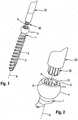
- Fig. 1
- shows a perspective view of a screw element according to a first embodiment with a portion of a screw driver adapted to a drive portion of the screw element.
- Fig. 2
- shows an enlarged view of a detail of
Fig. 1 . - Fig. 3
- shows a perspective view from the top onto the screw element of
Figs. 1 and 2 . - Fig. 4
- shows a top view onto the screw element of
Figs. 1 to 3 . - Fig. 5
- shows a cross-sectional view of the screw element of
Figs. 1 to 4 along line A-A inFig. 4 . - Fig. 6
- shows a side view onto a screw driver with an engagement portion adapted to the drive portion of the screw element of
Figs. 1 to 5 . - Fig. 7
- shows an enlarged perspective view onto the engagement portion of the screw driver of
Fig. 6 . - Fig. 8
- shows a perspective view from the top onto a screw element according to a modified embodiment.
- Fig. 9
- shows an enlarged perspective view of a step of using the screw element and the screw driver according to the first embodiment.
- Fig. 10
- shows a perspective view of a step of adjusting the insertion depth of the screw element.
- Figs. 11a) to 11c)
- show cross-sectional views of steps of engaging the drive portion of the screw element according to the first embodiment with the engagement portion of the screw driver.
- Fig. 12
- shows a perspective view of a second embodiment of the screw element in connection with a polyaxial bone anchor.
- Fig. 13
- shows a perspective view of a further application of the screw element in connection with a bone plate.
- Referring to
Figs. 1 to 5 , a screw element 1 according to a first embodiment comprises ashank 2 with a bone thread 3 in at least a portion of theshank 2 and ahead 4. Theshank 2 is configured to be inserted into a bone or in particular into a pedicle of a vertebra. A screw axis S is defined by the axis of the bone thread 3. Thehead 4 has the shape of a segment of a sphere and afree end 5 on a side that is opposite to theshank 2. The bone thread 3 defines a screw axis S. At thefree end 5, adrive portion 6 that is configured to be engaged with an engagement portion of a driver is provided. Thedrive portion 6 will be explained more in detail below. - A system of the screw element 1 with the
drive portion 6 and a screw driver includes ascrew driver 20 that has anengagement portion 30 adapted for engagement with thedrive portion 6 of the screw element 1. - As depicted in particular in
Figs. 3 to 5 , thedrive portion 6 of the screw element 1 comprises afirst recess 7 that is located at a distance from thefree end 5 and that has a substantially cylindrical main contour with a main inner diameter and with the cylinder axis being the screw axis S. In the cylinder wall of the substantially cylindricalfirst recess 7, a plurality oflongitudinal drive grooves 8 are formed. Thedrive grooves 8 each comprise a bottom line Bd that is parallel to the screw axis S (seeFig. 5 ). A cross-section of thedrive grooves 8 in a plane perpendicular to the screw axis S is substantially circular segment-shaped. Thedrive grooves 8 are arranged in a top view, as seen inFig. 4 , in a star-like manner. In a specific embodiment, thefirst recess 7 together with thedrive grooves 8 forms a torx-shaped drive structure that is configured to be engaged by a torx-shaped engagement portion of the screw driver. Theupper end 7a of therecess 7 is positioned at a distance from thefree end 5 of thehead 4. An axial depth from theend 7a to thelower end 7b of thefirst recess 7 corresponds substantially to a depth of usual drive recesses for screw elements of this type. In other words, the size of thefirst recess 7 with thedrive grooves 8 is sufficient for applying the necessary torque to the screw element 1. - Between the
first recess 7 and thefree end 5 there is asecond recess 9 that conically tapers from thefree end 5 towards thefirst recess 7. More in detail, the lower diameter of thesecond recess 9 is slightly larger than the main diameter of thefirst recess 7 and the upper diameter of thesecond recess 9 is greater than the lower diameter. The depth of thesecond recess 9 in the axial direction corresponds to approximately one fifth to one third of the depth of thefirst recess 7, preferably between one fourth and one third of the depth of thefirst recess 7. Thesecond recess 9 provides an enlarged bevelled surface that facilitates the insertion of theengagement portion 30 of thescrew driver 20. - A plurality of
guide grooves 10 are provided in the wall defining thesecond recess 9 at positions corresponding to the positions of thedrive grooves 8 in thefirst recess 7. Each of theguide grooves 10 comprises a longitudinal bottom line Bg that is parallel to the screw axis S and also parallel to the bottom line Bd of thecorresponding drive groove 8. Seen in a radial direction, the bottom line Bg of theguide groove 10 is farther away from the screw axis S than the bottom line Bd of thedrive groove 8. Hence, theguide groove 10 is at an axial position closest to theupper end 7a of the first recess deeper in the radial direction than thecorresponding drive groove 8. Due to the bevelled surface of thesecond recess 9, the depth of theguide grooves 10 gradually increases from thefree end 5 towards theguide groove 8. This results in a precise guiding of an engagement protrusion of thescrew driver 20 into thefirst recess 7 while simultaneously facilitating the engagement of the engagement protrusion with the guide groove at the outermost portion at thefree end 5 of theguide groove 10. - In a top view, the
guide grooves 10 have a greater width than thedrive grooves 8. The width of theguide grooves 10 perpendicular to the bottom line Bg decreases in a direction towards thefree end 5. - The
guide grooves 10 go over in thedrive grooves 8 through anintermediate section 11 with abevelled wall 11 a that conically narrows towards thedrive grooves 8. Theintermediate section 11 may have a considerably smaller axial height than thefirst recess 7 and also than thesecond recess 9. By means of this design, theintermediate section 11 and theguide grooves 10 form pocket-like recesses that allow to catch and guide the engagement protrusions of thescrew driver 20 into theguide grooves 8. - As depicted in
Figs. 6 and 7 , thescrew driver 20 comprises adrive shaft 21, ahandle 22 at one end of thedrive shaft 21 and theengagement portion 30 at the opposite end. Theengagement portion 30 has a substantially cylindrical main contour that fits into thefirst recess 7 and longitudinally extending rib-like engagement protrusions 31 that are sized so as to engage thedrive grooves 8 of thefirst recess 7 in order to apply torque onto the screw element 1. Theengagement portion 30 is bevelled towards thefree end surface 32 of the engagement portion that is substantially circular. In addition, theengagement protrusions 31 each have a bevelledfront end surface 31a. The length of the bevelledfront end surface 31a of theengagement projections 31 corresponds substantially to the length of the conical surface of thesecond recess 9 between thefree end 5 and theintermediate portion 11 of thedrive portion 6 of the screw element. An angle of inclination of the bevelledsurface 31 may be the same angle as that of theconical recess 9 or that of the slantedwall 11 a of theintermediate portion 11. Such an enlarged bevelled surface contributes to easily locate thedrive portion 6 of the screw element even in the case of a restricted view or no view to the operation site. - A modified embodiment of the screw element with a modification of the
drive portion 6 is shown inFig. 8 . All parts and portions that are identical to the first embodiment are marked with the same reference numerals and the description thereof is not repeated. The modified embodiment differs in the shape of the intermediate portion. The intermediate portion 11' comprises arounded wall 11a'. - Referring now to
Figs. 9 and 10 the application of the screw element and the screw driver according to the first embodiment will be explained. InFig. 9 , two screw elements 1 have already been inserted into the pedicles of twovertebrae 100. Each of the screw elements 1 comprises thedrive portion 6 as described before. The insertion depths of the screw elements 1 need to be further adjusted. This is performed with thescrew driver 20 that engages with theengagement portion 30 thecorresponding drive portion 6 of the screw element 1. Due to the design of thedrive portion 6 and theengagement portion 30 of the screw driver, the engagement of theengagement portion 30 with the drive portion is achieved quickly and easily, even if there is no or only a restricted view to the operation site. Therefore, it is possible to carry out the adjustment of a number of pedicle screws in a short time. - Referring now to
Figs. 11a) to 11c ) the function of theengagement portion 30 of thescrew driver 20 and thedrive portion 6 of the screw element is shown in more detail. As depicted inFig. 11a ), it may happen, that thescrew driver 20 is approaching the screw element in an inclined manner with respect to the screw axis S. As further shown inFig. 11b ) theengagement portion 30 of thescrew driver 20 first engages the conicalsecond recess 9. When theengagement protrusions 31 of theengagement portion 30 of thescrew driver 20 begin to engage theguide grooves 10, thescrew driver 20 is automatically aligned while penetrating further into thedrive portion 6. Theguide grooves 10 and theintermediate portion 11 guide theengagement portion 30 into thedrive grooves 8 so that the screw element 1 and thescrew driver 20 become aligned and connected in a form-fit manner to each other. Then, torque can be applied with thescrew driver 20 onto the screw element 1. It shall be noted that due to the decreasing depth and width of theguide grooves 10 towards thefree end 5, theengagement portion 30 can be easily rotated until the engagement protrusions locate and engage theengagement grooves 10. - A second embodiment of a screw element will be explained with reference to
Fig. 12 . Parts and portions that are identical to the previous embodiments have the same reference numerals and the description thereof is not repeated. In this embodiment, the screw element is aset screw 40 that is used in a polyaxialbone anchoring device 50. The polyaxialbone anchoring device 50 is shown only in an exemplary manner, many different designs of such polyaxial bone anchoring device may be contemplated. The polyaxialbone anchoring device 50 comprises a screw element 1' that has a spherical segment-shaped head (not shown) and that may have a known drive portion, such as, for example, a known torx-shaped drive portion or a polygon-shaped drive portion or that may have also adrive portion 6 according to the previous embodiments. The screw element 1' is pivotably connected to a receivingpart 51 that comprises a seat to hold the head of the screw element in a ball and socket manner. A pressure element (not shown) may be provided to exert pressure onto the head. The receivingpart 51 comprises a substantiallyU-shaped recess 52 that is configured to receive arod 200 therein. The rod is intended to be connected to a plurality of bone anchors. To lock therod 200 in the receivingpart 51 and also to lock the head in its pivot position relative to the receivingpart 51, a locking element in the form of aset screw 40 is used that cooperates with a thread provided in the receivingpart 51. It may be the case, that once the head and the rod are locked, further adjustments become necessary. In such a case theset screw 40 has to be loosened and tightened again after correcting the angular position of the receiving part relative to the head or after correcting the position of the rod. For such adjustments, thescrew driver 20 that cooperates with thedrive portion 6 in theset screw 40 may be used. Hence, the adjustments can be performed quickly and easily. - It should be noted, that such a type of set screw having the
engagement portion 6 could also be used for a monoaxial bone anchor in which the screw element and the receiving part are fixed relative to each other. - A further application is shown in
Fig. 13. Fig 13 depicts abone plate 60 that is used with screw elements 1, for example, in orthopedic and trauma surgery to immobilize broken bone parts. The screw elements 1 are of the type according toFigs. 1 to 5 and8 and comprise thedrive portion 6 in their head. The head may be spherical segment-shaped so that the screw element 1 can be placed within a hole of the bone plate at various angles. Alternatively, the head may have a shape that allows to place the screw element only at a fixed angle with respect to thebone plate 60. Also in such cases, an adjustment of the insertion depth of the bone screw may be necessary. This is facilitated by using the screw element with thedrive portion 6 and acorresponding screw driver 20. In a still further modification, a locking element may be provided in the holes of the bone plate to prevent pull-out of the bone screw, wherein the locking element comprises thedrive portion 6. - Further embodiments and modifications of the previously described embodiments may be contemplated. The size and the angle of the bevelled surface of the
second recess 9 and of theguide grooves 8, as well as of theintermediate portion 11, 11' can be varied. Thewall intermediate portion 11, 11' may have any shape that is configured to guide the engagement portion of the screw driver into thefirst recess 7. - In the embodiment shown, an even number of drive grooves is shown and each drive groove is positioned opposite to another drive groove. However, also an odd number of drive grooves may be contemplated and one drive groove may not be opposite to another drive groove. The same applies to the corresponding guide grooves.
- Instead of the torx-shape of the drive grooves, also a polygonal shape of the first recess may be contemplated. In such a case, the corners of the polygon are considered as the drive grooves.
- The bottom lines of the drive grooves and the guide grooves may also be twisted around the screw axis. Also, the bottom lines need not to be exactly parallel to the screw axis.
Claims (14)
- A screw element for use in spinal, orthopedic or trauma surgery, the screw element including
a screw axis (S) and a screw thread (3);
a drive portion (6) for engagement with a screw driver (20), wherein the drive portion (6) comprises a first recess (7) with a wall and substantially longitudinally extending drive grooves (8) formed in the wall,
a second recess (9) between a free end (5) of the screw element (1, 1') and the first recess (7), wherein the second recess (9) has a wall and a gradually increasing inner diameter towards the free end (5);
wherein in the wall of the second recess (9) guide grooves (10) are formed at positions corresponding to the position of the drive grooves (8) that allow an engagement portion (30) of a screw driver (20) to be guided to engage the drive grooves (8),
wherein the guide grooves (10) comprise a bottom line (Bg) that is further away from the screw axis (S) than a bottom line (Bd) of the drive grooves (8). - The screw element of claim 1, wherein the first recess (7) is substantially cylindrical and the drive grooves (8) extend substantially parallel to the screw axis.
- The screw element of claim 1 or 2, wherein the first recess (7) with the drive grooves (8) has a torx-shape.
- The screw element of one of claims 1 to 3, wherein the second recess (9) is substantially conical with increasing diameter towards the free end (5) of the screw element.
- The screw element of claim 4, wherein an axial length of the second recess (9) is between one fifth and a half of the axial length of the first recess, preferably between one fourth and one third of the axial length of the first recess (7).
- The screw element of claim 5, wherein a depth of the guide grooves (10) increases in a direction from the free end (5) towards the first recess (7).
- The screw element of one of claims 1 to 6, wherein a width of the guide grooves (10) increases in a direction from the free end (5) towards the first recess (7).
- The screw element of one of claims 1 to 7, wherein a width of the guide grooves (10) is greater than a width of the drive grooves (8) at a position closest to the first recess (7).
- The screw element of one of claims 1 to 6, wherein an inclined shoulder (11) is provided at an end of each guide groove (10) adjacent to the drive groove (8).
- The screw element of one of claims 1 to 8, wherein the screw element (1) is a bone screw comprising a shank (2) with a bone thread in at least a portion thereof and with a head (4) having a free end (5) opposite to the shank (2) and wherein the drive portion (6) is provided in the head (4).
- The screw element of claim 10, wherein the head (4) has a spherical segment-shaped outer surface portion.
- The screw element of one of claims 1 to 12, wherein the screw element is a set screw (40) configured to be used as a locking element for a polyaxial bone screw (50) or a locking element for a bone plate.
- A system comprising a screw element according to claims 1 to 12 and a screw driver, the screw driver (20) comprising a drive axis and engagement portion (30) with engagement protrusions extending in a longitudinal direction parallel to the drive axis and configured to engage the drive grooves (8) of the screw element (1),
wherein the engagement protrusions (31) comprise a bevelled front end (31a) with the length of the bevel corresponding substantially to the length of the guide grooves (10). - The system of claim 13, wherein the engagement protrusions have a torx-shape in a cross-sectional view perpendicular to the drive axis.
Priority Applications (8)
| Application Number | Priority Date | Filing Date | Title |
|---|---|---|---|
| EP14164692.7AEP2932929B1 (en) | 2014-04-15 | 2014-04-15 | A screw element for use in spinal, orthopedic or trauma surgery and a system of such a screw element and a screw driver adapted thereto |
| JP2015080922AJP6612515B2 (en) | 2014-04-15 | 2015-04-10 | Screw elements for use in spinal surgery, orthopedic surgery, or trauma surgery, as well as such screw elements and screw driver systems adapted thereto |
| CN201510167329.1ACN105030320B (en) | 2014-04-15 | 2015-04-10 | screw element and system of the screw element and screw driver |
| TW104111513ATW201538121A (en) | 2014-04-15 | 2015-04-10 | A screw element for use in spinal, orthopedic or trauma surgery and a system of such a screw element and a screw driver adapted thereto |
| US14/685,433US9867639B2 (en) | 2014-04-15 | 2015-04-13 | Screw element for use in spinal, orthopedic or trauma surgery and a system of such a screw element and a screw driver adapted thereto |
| KR1020150051907AKR20150118914A (en) | 2014-04-15 | 2015-04-13 | A screw element for use in spinal, orthopedic or trauma surgery and a system of such a screw element and a screw driver adapted thereto |
| US15/830,858US10335198B2 (en) | 2014-04-15 | 2017-12-04 | Screw element for use in spinal, orthopedic or trauma surgery and a system of such a screw element and a screw driver adapted thereto |
| US16/416,955US11045226B2 (en) | 2014-04-15 | 2019-05-20 | Screw element for use in spinal, orthopedic or trauma surgery and a system of such a screw element and a screw driver adapted thereto |
Applications Claiming Priority (1)
| Application Number | Priority Date | Filing Date | Title |
|---|---|---|---|
| EP14164692.7AEP2932929B1 (en) | 2014-04-15 | 2014-04-15 | A screw element for use in spinal, orthopedic or trauma surgery and a system of such a screw element and a screw driver adapted thereto |
Publications (2)
| Publication Number | Publication Date |
|---|---|
| EP2932929A1 EP2932929A1 (en) | 2015-10-21 |
| EP2932929B1true EP2932929B1 (en) | 2017-02-08 |
Family
ID=50478770
Family Applications (1)
| Application Number | Title | Priority Date | Filing Date |
|---|---|---|---|
| EP14164692.7AActiveEP2932929B1 (en) | 2014-04-15 | 2014-04-15 | A screw element for use in spinal, orthopedic or trauma surgery and a system of such a screw element and a screw driver adapted thereto |
Country Status (6)
| Country | Link |
|---|---|
| US (3) | US9867639B2 (en) |
| EP (1) | EP2932929B1 (en) |
| JP (1) | JP6612515B2 (en) |
| KR (1) | KR20150118914A (en) |
| CN (1) | CN105030320B (en) |
| TW (1) | TW201538121A (en) |
Cited By (1)
| Publication number | Priority date | Publication date | Assignee | Title |
|---|---|---|---|---|
| US12433652B2 (en) | 2020-06-24 | 2025-10-07 | Mimeo Medical Gmbh | Tool attachment point with alignment aid for screw elements |
Families Citing this family (24)
| Publication number | Priority date | Publication date | Assignee | Title |
|---|---|---|---|---|
| US8231635B2 (en)* | 2007-01-18 | 2012-07-31 | Stryker Spine | Polyaxial screwdriver for a pedicle screw system |
| EP2932929B1 (en)* | 2014-04-15 | 2017-02-08 | Biedermann Technologies GmbH & Co. KG | A screw element for use in spinal, orthopedic or trauma surgery and a system of such a screw element and a screw driver adapted thereto |
| EP3231391B1 (en)* | 2016-04-14 | 2018-12-26 | Neoss Limited | Screwdriver and screw for medical applications, in particular for dental applications |
| EP3528740B1 (en) | 2016-12-16 | 2022-12-07 | Neoss Limited | Dental abutment blank and method of manufacturing a dental prosthesis from such a blank |
| DE102017101348A1 (en)* | 2017-01-25 | 2018-07-26 | Aesculap Ag | Axis accurate screwdriver |
| US20180347611A1 (en)* | 2017-06-02 | 2018-12-06 | Superior Tool Co., Ltd. | Screw and Corresponding Punch |
| KR102009789B1 (en) | 2017-11-29 | 2019-08-14 | 에이블 주식회사 | Medical manual driver |
| IT201800006879A1 (en)* | 2018-07-03 | 2020-01-03 | Improved kit for orthopedics, preferably for osteosynthesis. | |
| USD892604S1 (en)* | 2018-11-08 | 2020-08-11 | Superior Tool Co., Ltd. | Screw |
| DE102018132840A1 (en)* | 2018-12-19 | 2020-06-25 | Herrmann Ultraschalltechnik Gmbh & Co. Kg | Ultrasonic welding system with positive connection |
| DE102018132837A1 (en) | 2018-12-19 | 2020-06-25 | Herrmann Ultraschalltechnik Gmbh & Co. Kg | Ultrasonic welding system |
| EP3705069B1 (en) | 2019-03-05 | 2023-02-22 | K2M, Inc. | Automatic ratcheting screwdriver |
| US11020154B2 (en)* | 2019-04-26 | 2021-06-01 | Warsaw Orthopedic, Inc. | Surgical instrument and methods of use |
| US12070253B2 (en)* | 2019-06-07 | 2024-08-27 | Smith & Nephew, Inc. | Orthopedic implant with improved variable angle locking mechanism |
| ES2988747T3 (en)* | 2019-07-02 | 2024-11-21 | Neo Medical Sa | System to prevent lateral tension on bone structures resulting from off-axis forces caused by the screwdriver and screw extender |
| EP3763322A1 (en)* | 2019-07-10 | 2021-01-13 | Tech Xika PTT, S.L. | Prosthetic dental screw, tightening tool and coupling system between the two |
| KR20210016109A (en) | 2019-07-31 | 2021-02-15 | 서울대학교병원 | Driver for Surgical Operation of Spine |
| US11426225B2 (en) | 2019-12-03 | 2022-08-30 | DePuy Synthes Products, Inc. | Screw extraction shaft |
| DE102020004179B4 (en)* | 2020-07-11 | 2023-11-16 | ORTHO HUB VENTURES UG (haftungsbeschränkt) | Screw element and system consisting of a screwdriver and at least one such screw element |
| TWI773142B (en)* | 2021-02-19 | 2022-08-01 | 健寶生技股份有限公司 | Bone locking system and method |
| WO2023049113A1 (en)* | 2021-09-21 | 2023-03-30 | Treace Medical Concepts, Inc. | Tapered lobular surgical driver and implant system and technique for disengaging driver during surgery |
| USD1069121S1 (en)* | 2022-06-01 | 2025-04-01 | Curiteva, Inc. | Pedicle screw |
| JP2025518714A (en)* | 2022-06-01 | 2025-06-19 | サージカル デザイン イノベーションズ エルエルシー | Separable bone fixation devices and related methods |
| USD1081313S1 (en)* | 2022-09-22 | 2025-07-01 | Apex Brands, Inc. | Extractor insert |
Family Cites Families (103)
| Publication number | Priority date | Publication date | Assignee | Title |
|---|---|---|---|---|
| US2140449A (en)* | 1937-02-10 | 1938-12-13 | Continental Screw Company | Screw with socketed head and plurality of slots |
| US2538350A (en)* | 1945-09-05 | 1951-01-16 | Gerhard H J Baule | Socket head screw |
| US2777353A (en)* | 1952-10-30 | 1957-01-15 | Robert W Willis | Screw socket construction having tool guiding means formed therein |
| US2969250A (en)* | 1959-01-05 | 1961-01-24 | Standard Pressed Steel Co | Socket drive |
| US3584667A (en)* | 1966-09-19 | 1971-06-15 | Textron Inc | Coupling arrangement and tools for same |
| US4084478A (en)* | 1974-09-12 | 1978-04-18 | Phillips Screw Company | Screw heads |
| US4202244A (en)* | 1978-07-26 | 1980-05-13 | Technofast, Inc. | Recessed head screw |
| US4269246A (en)* | 1979-05-10 | 1981-05-26 | Textron Inc. | Fastener and driver assembly |
| US5019080A (en)* | 1990-02-13 | 1991-05-28 | Trextron Inc. | Drive system for prosthetic fasteners |
| US5105690A (en)* | 1991-03-29 | 1992-04-21 | Implant Innovations, Inc. | Manipulator-driver for holding and driving a screw-type article |
| DE4124472A1 (en)* | 1991-07-24 | 1993-01-28 | Adolf Wuerth Gmbh & Co Kg | SCREW |
| US5171117A (en)* | 1991-10-16 | 1992-12-15 | Textron Inc. | Fastener with multilobular internal recess and tool entry ramps |
| US5291811A (en)* | 1992-05-14 | 1994-03-08 | Textron Inc. | Back-side taper wedging drive system |
| JPH0737805B2 (en)* | 1992-11-17 | 1995-04-26 | 有限会社新城製作所 | Recessed screw and its driver bit |
| JPH0663916U (en)* | 1993-02-17 | 1994-09-09 | マックス株式会社 | Driving screw |
| IT1269314B (en)* | 1994-04-14 | 1997-03-26 | Carlo Sala | SCREW AND RELATIVE SCREWING TOOL |
| US5697979A (en)* | 1995-05-19 | 1997-12-16 | Pignataro; Anthony S. | Method and apparatus for securing a hair prosthesis to the human head |
| EP0933538B1 (en)* | 1996-10-24 | 2006-08-09 | Katsuyuki Totsu | Screw, driver bit and header punch for manufacture of screw |
| DE69929304T2 (en)* | 1998-02-24 | 2006-08-31 | Katsuyuki Totsu | SCREWDRIVER INSERT AND ITS COMBINATION WITH A SCREW |
| US6302632B1 (en)* | 1998-11-17 | 2001-10-16 | Chao-Wei Lin | Screw with compound recesses |
| US6048343A (en)* | 1999-06-02 | 2000-04-11 | Mathis; John M. | Bone screw system |
| JP4493135B2 (en)* | 2000-01-06 | 2010-06-30 | 勝行 戸津 | Screw and driver bit combination |
| JP3081613U (en)* | 2001-05-08 | 2001-11-16 | 若井産業株式会社 | Drilling tool |
| US6948408B1 (en)* | 2001-08-17 | 2005-09-27 | Howard Lee | Flat ended double cube shaped tipped, screwdriver system |
| US20030059276A1 (en)* | 2001-09-26 | 2003-03-27 | Chen Chin Sun | Screw socket opening for receiving various tool bits |
| US6685412B2 (en)* | 2001-10-19 | 2004-02-03 | Cross Medical Products, Inc. | Multi-lobe torque driving recess and tool in particular for an orthopedic implant screw |
| US6648643B2 (en)* | 2001-12-19 | 2003-11-18 | Biolock International, Inc. | Dental implant/abutment interface and system having prong and channel interconnections |
| US6890139B2 (en)* | 2002-02-26 | 2005-05-10 | Phillips Screw Company | Fastener having recess useable with multiple drivers and method of manufacture |
| US6575057B1 (en)* | 2002-04-18 | 2003-06-10 | Lisle Corporation | Broken heater hose coupler removal tool and method of use |
| GB2390127B (en)* | 2002-05-10 | 2005-06-15 | Uniscrew Ltd | Integrated fastening system |
| JP4205990B2 (en)* | 2003-05-30 | 2009-01-07 | 日東精工株式会社 | Screw with drive hole and driver bit |
| US6988432B2 (en)* | 2003-11-06 | 2006-01-24 | Uniscrew Worldwide, Inc. | Multi-tiered-recess screws |
| US7771459B2 (en)* | 2004-06-07 | 2010-08-10 | Degima Gmbh | Fastener having torque optimized head |
| US7691133B2 (en) | 2004-11-30 | 2010-04-06 | Integra Lifesciences Corporation | Systems and methods for bone fixation |
| US7935137B2 (en)* | 2004-12-08 | 2011-05-03 | Depuy Spine, Inc. | Locking bone screw and spinal plate system |
| US7225710B2 (en)* | 2005-05-27 | 2007-06-05 | Synthes Gmbh | Combination driver and combination fastener |
| US7188554B2 (en)* | 2005-06-09 | 2007-03-13 | Atlas Spine, Inc. | Medical fastener and tool |
| US7325470B2 (en)* | 2005-06-16 | 2008-02-05 | Orthohelix Surgical Designs, Inc. | Self-centering screw and retaining screw driver for use in surgery |
| US20070043379A1 (en)* | 2005-08-04 | 2007-02-22 | Medtronic, Inc. | Bone screw/driver assembly and method |
| US20070037121A1 (en)* | 2005-08-10 | 2007-02-15 | Carter Robert D | Carry and drive device and method for dental implant and/or components thereof |
| US20090093844A1 (en)* | 2005-09-30 | 2009-04-09 | Jackson Roger P | Elastic covered dynamic stabilization connector and assembly |
| US8739660B2 (en)* | 2006-04-24 | 2014-06-03 | Ttapdrive As | Screw head and tool for use therewith |
| GB2437537A (en)* | 2006-04-24 | 2007-10-31 | Jone Edland | Screw head with hexalobular recess and corresponding tool |
| FI118510B (en)* | 2006-05-24 | 2007-12-14 | Bioretec Oy | System used with the implantation device |
| US8870931B2 (en)* | 2007-03-21 | 2014-10-28 | The University Of North Carolina At Chapel Hill | Anti-unscrewing and multi-angular fastening apparatuses and methods for surgical bone screw/plate systems |
| US7967849B2 (en)* | 2007-04-06 | 2011-06-28 | Warsaw Orthopedic, Inc. | Adjustable multi-axial spinal coupling assemblies |
| WO2008122446A1 (en)* | 2007-04-10 | 2008-10-16 | Stryker Trauma Gmbh | Bone screw holding device |
| US7947065B2 (en)* | 2008-11-14 | 2011-05-24 | Ortho Innovations, Llc | Locking polyaxial ball and socket fastener |
| PL2170192T3 (en)* | 2007-07-20 | 2011-07-29 | Synthes Gmbh | Polyaxial bone fixation element |
| US9439681B2 (en)* | 2007-07-20 | 2016-09-13 | DePuy Synthes Products, Inc. | Polyaxial bone fixation element |
| US20090069852A1 (en)* | 2007-09-06 | 2009-03-12 | Warsaw Orthopedic, Inc. | Multi-Axial Bone Anchor Assembly |
| US8038701B2 (en)* | 2007-10-22 | 2011-10-18 | K2M, Inc. | Uni-planar, taper lock bone screw |
| US8287576B2 (en)* | 2007-10-23 | 2012-10-16 | K2M, Inc. | Mono-axial, taper lock bone screw |
| JP5651472B2 (en)* | 2007-10-23 | 2015-01-14 | ケー2エム, インコーポレイテッド | Posterior pedicle screw with taper lock |
| CN101539903A (en)* | 2008-03-18 | 2009-09-23 | 北京书生国际信息技术有限公司 | Method for realizing software compatible with documents in various formats |
| CA2742399A1 (en) | 2008-11-03 | 2010-06-03 | Dustin M. Harvey | Uni-planar bone fixation assembly |
| JP5095594B2 (en) | 2008-12-02 | 2012-12-12 | 株式会社ジーシー | Screw member |
| US20100256688A1 (en)* | 2009-04-03 | 2010-10-07 | Stryker Trauma Gmbh | Sonic screw |
| KR20120013312A (en)* | 2009-04-15 | 2012-02-14 | 신세스 게엠바하 | Orthodontic Connectors for Spinal Structures |
| US8500748B2 (en)* | 2009-09-25 | 2013-08-06 | Wasaw Orthopedic, Inc. | Tool and component engaging mechanism |
| US8361123B2 (en)* | 2009-10-16 | 2013-01-29 | Depuy Spine, Inc. | Bone anchor assemblies and methods of manufacturing and use thereof |
| ES2420989T3 (en) | 2010-02-26 | 2013-08-28 | Biedermann Technologies Gmbh & Co. Kg | Implant to stabilize bones or vertebrae |
| US8291795B2 (en)* | 2010-03-02 | 2012-10-23 | Phillips Screw Company | Fastener system with stable engagement and stick fit |
| US20110245839A1 (en)* | 2010-04-01 | 2011-10-06 | Zimmer, Inc. | Locking screw driver with increased torsional strength |
| NO20100558A1 (en)* | 2010-04-19 | 2011-10-20 | Ttapdrive As | Screw head and tools for use with it |
| DE102010029692B4 (en)* | 2010-06-04 | 2016-07-21 | Swg Schraubenwerk Gaisbach Gmbh & Co Kg | Rotary drive training |
| US8992544B2 (en)* | 2010-06-14 | 2015-03-31 | Orthopaedic International, Inc. | Tool and set screw for use in spinal implant systems |
| US8491641B2 (en)* | 2010-09-28 | 2013-07-23 | Spinofix, Inc. | Pedicle screws and dynamic adaptors |
| US10111694B2 (en)* | 2010-10-05 | 2018-10-30 | Skeletal Design Partnership, Llc | Pedicle screw assembly and method of assembly |
| CN102486196A (en)* | 2010-12-06 | 2012-06-06 | 鸿富锦精密工业(深圳)有限公司 | Fasteners, driving parts associated with them, and punches for forming the fasteners |
| CN102562755A (en)* | 2010-12-28 | 2012-07-11 | 鸿富锦精密工业(深圳)有限公司 | Fastener, driving piece matched with same and punch for forming fastener |
| GB2493031B (en)* | 2011-07-22 | 2015-05-13 | Ttapdrive As | Screw head and tool for use therewith |
| US20130030476A1 (en)* | 2011-07-29 | 2013-01-31 | Warsaw Orthopedic, Inc. | Bone screw/driver assembly having surface roughness |
| CA2846336C (en)* | 2011-08-25 | 2021-02-23 | Infastech Intellectual Properties Pte. Ltd. | Tapered lobular driver and fastener |
| JP5204887B2 (en)* | 2011-11-30 | 2013-06-05 | 日東精工株式会社 | Screw part head drive hole |
| EP2607722B1 (en)* | 2011-12-22 | 2014-02-26 | Straumann Holding AG | Connecting screw for a dental implant |
| US9198769B2 (en)* | 2011-12-23 | 2015-12-01 | Pioneer Surgical Technology, Inc. | Bone anchor assembly, bone plate system, and method |
| US8911479B2 (en)* | 2012-01-10 | 2014-12-16 | Roger P. Jackson | Multi-start closures for open implants |
| EP2676622B1 (en)* | 2012-06-18 | 2015-12-30 | Biedermann Technologies GmbH & Co. KG | Bone anchor |
| US9265542B2 (en)* | 2012-06-27 | 2016-02-23 | DePuy Synthes Products, Inc. | Variable angle bone fixation device |
| US20140066945A1 (en)* | 2012-08-31 | 2014-03-06 | Warsaw Orthopedic, Inc. | Surgical implant system and method |
| US20140214084A1 (en)* | 2013-01-28 | 2014-07-31 | Roger P. Jackson | Polyaxial bone anchor with receiver with spheric edge for friction fit |
| US20140236247A1 (en)* | 2013-02-20 | 2014-08-21 | Warsaw Orthopedic, Inc. | Surgical implant system and method |
| US9724149B2 (en)* | 2013-03-07 | 2017-08-08 | Warsaw Orhtopedic, Inc. | Surgical implant system and method |
| US9358060B2 (en)* | 2013-07-25 | 2016-06-07 | Zimmer Spine, Inc. | Self-retaining driver for a bone screw |
| US9840002B2 (en)* | 2013-09-30 | 2017-12-12 | Lew C. Schon | Modular driver and screw system |
| DE102013113401A1 (en)* | 2013-12-03 | 2015-06-03 | Adolf Würth GmbH & Co. KG | Screw and drive element with chamfer |
| US10076373B2 (en)* | 2014-03-12 | 2018-09-18 | Intrepid Orthopedics | Self-retaining fastener and driver |
| EP2932929B1 (en)* | 2014-04-15 | 2017-02-08 | Biedermann Technologies GmbH & Co. KG | A screw element for use in spinal, orthopedic or trauma surgery and a system of such a screw element and a screw driver adapted thereto |
| USD752174S1 (en)* | 2014-09-24 | 2016-03-22 | Crosman Corporation | Wadcutter airgun pellet |
| US20170095909A1 (en)* | 2015-10-05 | 2017-04-06 | Essence Method Refine Co., Ltd. | Recessed fastener, forming punch and driving tool |
| DE102016108972A1 (en)* | 2016-05-13 | 2017-11-16 | Aesculap Ag | Bone thread pedicle screw of large diameter |
| EP3472475A1 (en)* | 2016-06-17 | 2019-04-24 | Phillips Screw Company | High strength fasteners, drivers, and fastener systems |
| US10485594B2 (en)* | 2016-10-04 | 2019-11-26 | Amendia, Inc. | Modular tulip assembly |
| IT201600099434A1 (en)* | 2016-10-04 | 2018-04-04 | Fontana Fasteners R D S R L | Screw with hollow head. |
| DE102016119234A1 (en)* | 2016-10-10 | 2018-04-12 | Syntellix Ag | Screw drive with integrated torque lock |
| DE102017101348A1 (en)* | 2017-01-25 | 2018-07-26 | Aesculap Ag | Axis accurate screwdriver |
| US10428859B2 (en)* | 2017-06-05 | 2019-10-01 | The Hillman Group, Inc. | Combination recess for driven fastener |
| WO2019046893A1 (en)* | 2017-09-08 | 2019-03-14 | Device Synergies, PTY LTD | CANNULA FIXING DEVICE |
| US10995788B2 (en)* | 2017-12-15 | 2021-05-04 | Phillips Screw Company | Stick fit fastener recess system |
| EP3914832A4 (en)* | 2019-01-24 | 2022-12-07 | Acument Intellectual Properties LLC | IMPROVED STICK-FIT BIT DESIGN |
| USD888544S1 (en)* | 2019-01-28 | 2020-06-30 | National Nail Corp. | Fastener head |
| USD883765S1 (en)* | 2019-01-28 | 2020-05-12 | National Nail Corp. | Tool bit |
- 2014
- 2014-04-15EPEP14164692.7Apatent/EP2932929B1/enactiveActive
- 2015
- 2015-04-10JPJP2015080922Apatent/JP6612515B2/enactiveActive
- 2015-04-10TWTW104111513Apatent/TW201538121A/enunknown
- 2015-04-10CNCN201510167329.1Apatent/CN105030320B/enactiveActive
- 2015-04-13KRKR1020150051907Apatent/KR20150118914A/ennot_activeWithdrawn
- 2015-04-13USUS14/685,433patent/US9867639B2/enactiveActive
- 2017
- 2017-12-04USUS15/830,858patent/US10335198B2/enactiveActive
- 2019
- 2019-05-20USUS16/416,955patent/US11045226B2/enactiveActive
Non-Patent Citations (1)
| Title |
|---|
| None* |
Cited By (1)
| Publication number | Priority date | Publication date | Assignee | Title |
|---|---|---|---|---|
| US12433652B2 (en) | 2020-06-24 | 2025-10-07 | Mimeo Medical Gmbh | Tool attachment point with alignment aid for screw elements |
Also Published As
| Publication number | Publication date |
|---|---|
| US20190365422A1 (en) | 2019-12-05 |
| KR20150118914A (en) | 2015-10-23 |
| US10335198B2 (en) | 2019-07-02 |
| US20180140331A1 (en) | 2018-05-24 |
| US9867639B2 (en) | 2018-01-16 |
| EP2932929A1 (en) | 2015-10-21 |
| US11045226B2 (en) | 2021-06-29 |
| JP6612515B2 (en) | 2019-11-27 |
| TW201538121A (en) | 2015-10-16 |
| CN105030320B (en) | 2019-12-10 |
| JP2015202411A (en) | 2015-11-16 |
| US20150289905A1 (en) | 2015-10-15 |
| CN105030320A (en) | 2015-11-11 |
Similar Documents
| Publication | Publication Date | Title |
|---|---|---|
| EP2932929B1 (en) | A screw element for use in spinal, orthopedic or trauma surgery and a system of such a screw element and a screw driver adapted thereto | |
| US10478227B2 (en) | Orthopedic fixation devices and methods of installation thereof | |
| US11172961B2 (en) | Orthopedic fixation devices and methods of installation thereof | |
| US8603145B2 (en) | Coaxially lockable poly-axial bone fastener assemblies | |
| US7833251B1 (en) | System and method for performing spinal fixation | |
| US11446065B2 (en) | Self in-fusing pedicle screw implant | |
| US9198694B2 (en) | Orthopedic fixation devices and methods of installation thereof | |
| US20080077143A1 (en) | Apparatus for connecting a longitudinal member to a bone portion | |
| US20110087288A1 (en) | Surgical Fixation System and Related Methods | |
| US20180256213A1 (en) | Orthopedic fixation devices and methods of installation thereof | |
| US11576709B2 (en) | Bone fixation system and methods of use | |
| US11633219B2 (en) | Fenestrated pedicle nail | |
| US20050245933A1 (en) | Multi coaxial screw system | |
| US12156679B2 (en) | Orthopedic fixation devices and methods of installation thereof |
Legal Events
| Date | Code | Title | Description |
|---|---|---|---|
| PUAI | Public reference made under article 153(3) epc to a published international application that has entered the european phase | Free format text:ORIGINAL CODE: 0009012 | |
| AK | Designated contracting states | Kind code of ref document:A1 Designated state(s):AL AT BE BG CH CY CZ DE DK EE ES FI FR GB GR HR HU IE IS IT LI LT LU LV MC MK MT NL NO PL PT RO RS SE SI SK SM TR | |
| AX | Request for extension of the european patent | Extension state:BA ME | |
| 17P | Request for examination filed | Effective date:20151217 | |
| RBV | Designated contracting states (corrected) | Designated state(s):AL AT BE BG CH CY CZ DE DK EE ES FI FR GB GR HR HU IE IS IT LI LT LU LV MC MK MT NL NO PL PT RO RS SE SI SK SM TR | |
| 17Q | First examination report despatched | Effective date:20160323 | |
| GRAP | Despatch of communication of intention to grant a patent | Free format text:ORIGINAL CODE: EPIDOSNIGR1 | |
| INTG | Intention to grant announced | Effective date:20160823 | |
| GRAS | Grant fee paid | Free format text:ORIGINAL CODE: EPIDOSNIGR3 | |
| GRAA | (expected) grant | Free format text:ORIGINAL CODE: 0009210 | |
| AK | Designated contracting states | Kind code of ref document:B1 Designated state(s):AL AT BE BG CH CY CZ DE DK EE ES FI FR GB GR HR HU IE IS IT LI LT LU LV MC MK MT NL NO PL PT RO RS SE SI SK SM TR | |
| REG | Reference to a national code | Ref country code:GB Ref legal event code:FG4D | |
| REG | Reference to a national code | Ref country code:CH Ref legal event code:EP Ref country code:CH Ref legal event code:NV Representative=s name:NOVAGRAAF INTERNATIONAL SA, CH Ref country code:AT Ref legal event code:REF Ref document number:866536 Country of ref document:AT Kind code of ref document:T Effective date:20170215 | |
| REG | Reference to a national code | Ref country code:IE Ref legal event code:FG4D | |
| REG | Reference to a national code | Ref country code:DE Ref legal event code:R096 Ref document number:602014006679 Country of ref document:DE | |
| REG | Reference to a national code | Ref country code:LT Ref legal event code:MG4D | |
| REG | Reference to a national code | Ref country code:NL Ref legal event code:MP Effective date:20170208 | |
| REG | Reference to a national code | Ref country code:AT Ref legal event code:MK05 Ref document number:866536 Country of ref document:AT Kind code of ref document:T Effective date:20170208 | |
| PG25 | Lapsed in a contracting state [announced via postgrant information from national office to epo] | Ref country code:FI Free format text:LAPSE BECAUSE OF FAILURE TO SUBMIT A TRANSLATION OF THE DESCRIPTION OR TO PAY THE FEE WITHIN THE PRESCRIBED TIME-LIMIT Effective date:20170208 Ref country code:HR Free format text:LAPSE BECAUSE OF FAILURE TO SUBMIT A TRANSLATION OF THE DESCRIPTION OR TO PAY THE FEE WITHIN THE PRESCRIBED TIME-LIMIT Effective date:20170208 Ref country code:GR Free format text:LAPSE BECAUSE OF FAILURE TO SUBMIT A TRANSLATION OF THE DESCRIPTION OR TO PAY THE FEE WITHIN THE PRESCRIBED TIME-LIMIT Effective date:20170509 Ref country code:LT Free format text:LAPSE BECAUSE OF FAILURE TO SUBMIT A TRANSLATION OF THE DESCRIPTION OR TO PAY THE FEE WITHIN THE PRESCRIBED TIME-LIMIT Effective date:20170208 Ref country code:NO Free format text:LAPSE BECAUSE OF FAILURE TO SUBMIT A TRANSLATION OF THE DESCRIPTION OR TO PAY THE FEE WITHIN THE PRESCRIBED TIME-LIMIT Effective date:20170508 | |
| PG25 | Lapsed in a contracting state [announced via postgrant information from national office to epo] | Ref country code:AT Free format text:LAPSE BECAUSE OF FAILURE TO SUBMIT A TRANSLATION OF THE DESCRIPTION OR TO PAY THE FEE WITHIN THE PRESCRIBED TIME-LIMIT Effective date:20170208 Ref country code:LV Free format text:LAPSE BECAUSE OF FAILURE TO SUBMIT A TRANSLATION OF THE DESCRIPTION OR TO PAY THE FEE WITHIN THE PRESCRIBED TIME-LIMIT Effective date:20170208 Ref country code:BG Free format text:LAPSE BECAUSE OF FAILURE TO SUBMIT A TRANSLATION OF THE DESCRIPTION OR TO PAY THE FEE WITHIN THE PRESCRIBED TIME-LIMIT Effective date:20170508 Ref country code:PT Free format text:LAPSE BECAUSE OF FAILURE TO SUBMIT A TRANSLATION OF THE DESCRIPTION OR TO PAY THE FEE WITHIN THE PRESCRIBED TIME-LIMIT Effective date:20170608 Ref country code:NL Free format text:LAPSE BECAUSE OF NON-PAYMENT OF DUE FEES Effective date:20170208 Ref country code:SE Free format text:LAPSE BECAUSE OF FAILURE TO SUBMIT A TRANSLATION OF THE DESCRIPTION OR TO PAY THE FEE WITHIN THE PRESCRIBED TIME-LIMIT Effective date:20170208 Ref country code:ES Free format text:LAPSE BECAUSE OF FAILURE TO SUBMIT A TRANSLATION OF THE DESCRIPTION OR TO PAY THE FEE WITHIN THE PRESCRIBED TIME-LIMIT Effective date:20170208 Ref country code:RS Free format text:LAPSE BECAUSE OF FAILURE TO SUBMIT A TRANSLATION OF THE DESCRIPTION OR TO PAY THE FEE WITHIN THE PRESCRIBED TIME-LIMIT Effective date:20170208 | |
| PG25 | Lapsed in a contracting state [announced via postgrant information from national office to epo] | Ref country code:CZ Free format text:LAPSE BECAUSE OF FAILURE TO SUBMIT A TRANSLATION OF THE DESCRIPTION OR TO PAY THE FEE WITHIN THE PRESCRIBED TIME-LIMIT Effective date:20170208 Ref country code:RO Free format text:LAPSE BECAUSE OF FAILURE TO SUBMIT A TRANSLATION OF THE DESCRIPTION OR TO PAY THE FEE WITHIN THE PRESCRIBED TIME-LIMIT Effective date:20170208 Ref country code:IT Free format text:LAPSE BECAUSE OF FAILURE TO SUBMIT A TRANSLATION OF THE DESCRIPTION OR TO PAY THE FEE WITHIN THE PRESCRIBED TIME-LIMIT Effective date:20170208 Ref country code:SK Free format text:LAPSE BECAUSE OF FAILURE TO SUBMIT A TRANSLATION OF THE DESCRIPTION OR TO PAY THE FEE WITHIN THE PRESCRIBED TIME-LIMIT Effective date:20170208 Ref country code:EE Free format text:LAPSE BECAUSE OF FAILURE TO SUBMIT A TRANSLATION OF THE DESCRIPTION OR TO PAY THE FEE WITHIN THE PRESCRIBED TIME-LIMIT Effective date:20170208 | |
| REG | Reference to a national code | Ref country code:DE Ref legal event code:R097 Ref document number:602014006679 Country of ref document:DE | |
| PG25 | Lapsed in a contracting state [announced via postgrant information from national office to epo] | Ref country code:PL Free format text:LAPSE BECAUSE OF FAILURE TO SUBMIT A TRANSLATION OF THE DESCRIPTION OR TO PAY THE FEE WITHIN THE PRESCRIBED TIME-LIMIT Effective date:20170208 Ref country code:SM Free format text:LAPSE BECAUSE OF FAILURE TO SUBMIT A TRANSLATION OF THE DESCRIPTION OR TO PAY THE FEE WITHIN THE PRESCRIBED TIME-LIMIT Effective date:20170208 Ref country code:DK Free format text:LAPSE BECAUSE OF FAILURE TO SUBMIT A TRANSLATION OF THE DESCRIPTION OR TO PAY THE FEE WITHIN THE PRESCRIBED TIME-LIMIT Effective date:20170208 | |
| PLBE | No opposition filed within time limit | Free format text:ORIGINAL CODE: 0009261 | |
| STAA | Information on the status of an ep patent application or granted ep patent | Free format text:STATUS: NO OPPOSITION FILED WITHIN TIME LIMIT | |
| 26N | No opposition filed | Effective date:20171109 | |
| REG | Reference to a national code | Ref country code:IE Ref legal event code:MM4A | |
| REG | Reference to a national code | Ref country code:FR Ref legal event code:ST Effective date:20171229 | |
| PG25 | Lapsed in a contracting state [announced via postgrant information from national office to epo] | Ref country code:FR Free format text:LAPSE BECAUSE OF NON-PAYMENT OF DUE FEES Effective date:20170502 Ref country code:MC Free format text:LAPSE BECAUSE OF FAILURE TO SUBMIT A TRANSLATION OF THE DESCRIPTION OR TO PAY THE FEE WITHIN THE PRESCRIBED TIME-LIMIT Effective date:20170208 | |
| PG25 | Lapsed in a contracting state [announced via postgrant information from national office to epo] | Ref country code:SI Free format text:LAPSE BECAUSE OF FAILURE TO SUBMIT A TRANSLATION OF THE DESCRIPTION OR TO PAY THE FEE WITHIN THE PRESCRIBED TIME-LIMIT Effective date:20170208 Ref country code:LU Free format text:LAPSE BECAUSE OF NON-PAYMENT OF DUE FEES Effective date:20170415 | |
| REG | Reference to a national code | Ref country code:BE Ref legal event code:MM Effective date:20170430 | |
| PG25 | Lapsed in a contracting state [announced via postgrant information from national office to epo] | Ref country code:IE Free format text:LAPSE BECAUSE OF NON-PAYMENT OF DUE FEES Effective date:20170415 | |
| PG25 | Lapsed in a contracting state [announced via postgrant information from national office to epo] | Ref country code:BE Free format text:LAPSE BECAUSE OF NON-PAYMENT OF DUE FEES Effective date:20170430 | |
| PG25 | Lapsed in a contracting state [announced via postgrant information from national office to epo] | Ref country code:MT Free format text:LAPSE BECAUSE OF NON-PAYMENT OF DUE FEES Effective date:20170415 | |
| PG25 | Lapsed in a contracting state [announced via postgrant information from national office to epo] | Ref country code:HU Free format text:LAPSE BECAUSE OF FAILURE TO SUBMIT A TRANSLATION OF THE DESCRIPTION OR TO PAY THE FEE WITHIN THE PRESCRIBED TIME-LIMIT; INVALID AB INITIO Effective date:20140415 | |
| PG25 | Lapsed in a contracting state [announced via postgrant information from national office to epo] | Ref country code:CY Free format text:LAPSE BECAUSE OF FAILURE TO SUBMIT A TRANSLATION OF THE DESCRIPTION OR TO PAY THE FEE WITHIN THE PRESCRIBED TIME-LIMIT Effective date:20170208 | |
| PG25 | Lapsed in a contracting state [announced via postgrant information from national office to epo] | Ref country code:MK Free format text:LAPSE BECAUSE OF FAILURE TO SUBMIT A TRANSLATION OF THE DESCRIPTION OR TO PAY THE FEE WITHIN THE PRESCRIBED TIME-LIMIT Effective date:20170208 | |
| PG25 | Lapsed in a contracting state [announced via postgrant information from national office to epo] | Ref country code:TR Free format text:LAPSE BECAUSE OF FAILURE TO SUBMIT A TRANSLATION OF THE DESCRIPTION OR TO PAY THE FEE WITHIN THE PRESCRIBED TIME-LIMIT Effective date:20170208 | |
| PG25 | Lapsed in a contracting state [announced via postgrant information from national office to epo] | Ref country code:AL Free format text:LAPSE BECAUSE OF FAILURE TO SUBMIT A TRANSLATION OF THE DESCRIPTION OR TO PAY THE FEE WITHIN THE PRESCRIBED TIME-LIMIT Effective date:20170208 Ref country code:IS Free format text:LAPSE BECAUSE OF FAILURE TO SUBMIT A TRANSLATION OF THE DESCRIPTION OR TO PAY THE FEE WITHIN THE PRESCRIBED TIME-LIMIT Effective date:20170608 | |
| P01 | Opt-out of the competence of the unified patent court (upc) registered | Effective date:20230525 | |
| PGFP | Annual fee paid to national office [announced via postgrant information from national office to epo] | Ref country code:DE Payment date:20250429 Year of fee payment:12 | |
| PGFP | Annual fee paid to national office [announced via postgrant information from national office to epo] | Ref country code:GB Payment date:20250429 Year of fee payment:12 | |
| PGFP | Annual fee paid to national office [announced via postgrant information from national office to epo] | Ref country code:CH Payment date:20250501 Year of fee payment:12 |