EP2932034B1 - Determining gravity toolface and inclination in a rotating downhole tool - Google Patents
Determining gravity toolface and inclination in a rotating downhole toolDownload PDFInfo
- Publication number
- EP2932034B1 EP2932034B1EP12821090.3AEP12821090AEP2932034B1EP 2932034 B1EP2932034 B1EP 2932034B1EP 12821090 AEP12821090 AEP 12821090AEP 2932034 B1EP2932034 B1EP 2932034B1
- Authority
- EP
- European Patent Office
- Prior art keywords
- downhole tool
- accelerometer
- sensing device
- component
- rate sensing
- Prior art date
- Legal status (The legal status is an assumption and is not a legal conclusion. Google has not performed a legal analysis and makes no representation as to the accuracy of the status listed.)
- Active
Links
- 230000005484gravityEffects0.000titleclaimsdescription37
- 230000001133accelerationEffects0.000claimsdescription64
- 238000005553drillingMethods0.000claimsdescription26
- 238000000034methodMethods0.000claimsdescription16
- 238000004891communicationMethods0.000claimsdescription5
- 239000012530fluidSubstances0.000claimsdescription5
- 238000005259measurementMethods0.000description10
- 230000000712assemblyEffects0.000description9
- 238000000429assemblyMethods0.000description9
- 238000010586diagramMethods0.000description7
- 230000006870functionEffects0.000description3
- 230000008901benefitEffects0.000description2
- 230000015572biosynthetic processEffects0.000description2
- 238000010276constructionMethods0.000description2
- 238000011161developmentMethods0.000description2
- 229930195733hydrocarbonNatural products0.000description2
- 150000002430hydrocarbonsChemical class0.000description2
- 238000004519manufacturing processMethods0.000description2
- 230000005641tunnelingEffects0.000description2
- 241000251468ActinopterygiiSpecies0.000description1
- RWSOTUBLDIXVET-UHFFFAOYSA-NDihydrogen sulfideChemical compoundSRWSOTUBLDIXVET-UHFFFAOYSA-N0.000description1
- 230000009286beneficial effectEffects0.000description1
- 238000013461designMethods0.000description1
- 230000000694effectsEffects0.000description1
- 230000002349favourable effectEffects0.000description1
- 238000001914filtrationMethods0.000description1
- 229910000037hydrogen sulfideInorganic materials0.000description1
- 238000002347injectionMethods0.000description1
- 239000007924injectionSubstances0.000description1
- 239000000243solutionSubstances0.000description1
Images


Classifications
- E—FIXED CONSTRUCTIONS
- E21—EARTH OR ROCK DRILLING; MINING
- E21B—EARTH OR ROCK DRILLING; OBTAINING OIL, GAS, WATER, SOLUBLE OR MELTABLE MATERIALS OR A SLURRY OF MINERALS FROM WELLS
- E21B47/00—Survey of boreholes or wells
- E21B47/02—Determining slope or direction
- E21B47/024—Determining slope or direction of devices in the borehole
Definitions
- the present disclosurerelates generally to well drilling operations and, more particularly, to systems and methods for determining gravity toolface and inclination in a rotating downhole tool.
- a gravity toolface measurementmay be used to determine the rotational orientation of a downhole tool relative to the high side of a borehole. Accelerometers may be used for gravity toolface and inclination measurements, but any rotation of the tool during the measurement process may skew the measurements. This is particularly problematic in rotary steerable drilling systems, where electronics are located in a rotating portion of the drilling assembly. Current methods for correcting the rotational skew in the measurements typically require up to six accelerometers disposed in multiple radial and or axial locations along a tool.
- WO2007/014446 A1discloses an orientation sensing apparatus and a method for determining an orientation.
- the apparatusincludes an orientation sensor device and a rotation sensor device and generates a set of corrected orientation data using rotation data from the rotation sensor device.
- GB 2432176 Adiscloses a steering tool comprising a shaft and a housing, with sensor sets that each include at least one accelerometer and a shaft rotation rate sensor to derive an aggregate rotation rate.
- the present disclosurerelates generally to well drilling operations and, more particularly, to systems and methods for determining gravity toolface and inclination in a rotating downhole tool.
- the systems and methodshave more favorable geometric feasibility than a conventional solution requiring six accelerometers.
- Embodiments of the present disclosuremay be applicable to drilling operations that include horizontal, vertical, deviated, multilateral, u-tube connection, intersection, bypass (drill around a mid-depth stuck fish and back into the well below), or otherwise nonlinear wellbores in any type of subterranean formation.
- Embodimentsmay be applicable to injection wells, and production wells, including natural resource production wells such as hydrogen sulfide, hydrocarbons or geothermal wells; as well as borehole construction for river crossing tunneling and other such tunneling boreholes for near surface construction purposes or borehole u-tube pipelines used for the transportation of fluids such as hydrocarbons.
- Embodiments described below with respect to one implementationare not intended to be limiting.
- An embodimentmay comprise a downhole tool and a sensor assembly disposed in a radially offset location within the downhole tool.
- the sensor assemblycomprises three accelerometers and an angular rate sensing device.
- a processoris in communication with the sensor assembly and is coupled to at least one memory device.
- the memory devicecontains a set of instruction that, when executed by the processor, cause the processor to receive an output from the sensor assembly, to determine at least one of a centripetal acceleration and a tangential acceleration of the downhole tool based, at least in part, on the output, and to determine at least one of a gravity toolface and inclination of the downhole tool using at least one of the centripetal acceleration and the tangential acceleration.
- a system which is not claimed for determining gravity toolface and inclinationmay also comprise a downhole tool.
- a first sensor assemblymay be disposed in a first radially offset location within the downhole tool.
- the first sensor assemblymay comprise a first accelerometer and a second accelerometer.
- a second sensor assemblymay be disposed in a second radially offset location within the downhole tool.
- the second sensor assemblymay comprise a third accelerometer and a fourth accelerometer.
- a processormay be in communication with the first sensor assembly and the second sensor assembly, and coupled to at least one memory device.
- the memory devicemay contain a set of instruction that, when executed by the processor, cause the processor to receive a first output from the first sensor assembly and a second output from the second sensor assembly, determine at least one of a centripetal acceleration and a tangential acceleration of the downhole tool based, at least in part, on the first output and the second output, and determine at least one of a gravity toolface and inclination of the downhole tool using at least one of the centripetal acceleration and the tangential acceleration.
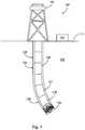
- Fig. 1is a diagram illustrating a drilling system 100, according to aspects of the present disclosure.
- the drilling system 100includes rig 101 at the surface 111 and positioned above borehole 103 within a subterranean formation 102.
- Rig 101may be coupled to a drilling assembly 104, comprising drill string 105 and bottom hole assembly (BHA) 106.
- BHA 106may comprise a drill bit 109, steering assembly 108, and an MWD apparatus 107.
- a control unit 114 at the surfacemay comprise a processor and memory device, and may communicate with elements of the BHA 106, in MWD apparatus 107 and steering assembly 108.
- the control unit 114may receive data from and send control signals to the BHA 106.
- the steering assembly 108may comprise a rotary steerable drilling system that controls the direction in which the borehole 103 is being drilled, and that is rotated along with the drill string 105 during drilling operations. In certain embodiments, the steering assembly 108 may angle the drill bit 109 to drill at an angle from the borehole 104. Maintaining the axial position of the drill bit 109 relative to the borehole 104 may require knowledge of the rotational position of the drill bit 109 relative to the borehole. A gravity toolface measurement may be used to determine the rotational orientation of the drill bit 113/steering assembly 108.
- a sensor assemblymay be incorporated into the drilling assembly 109 to determine both the gravity tool face and inclination of the drilling assembly during drilling operations, while the drilling assembly is rotating.
- the sensor assembly described hereinis not limited to determining the gravity toolface and inclination of a steering assembly, and may be used in a variety of downhole operations.
- the sensor assemblymay be disposed within a downhole tool, such as the MWD assembly 107 or the steering assembly 108.
- Fig. 2is a diagram illustrating a cross-section of an example downhole tool 200 which is not claimed comprising two sensor assemblies.
- downhole tool 200may include two sensor assemblies 205 and 206 positioned at diametrically opposite, radially offset locations 201 and 202, respectively, from the longitudinal axis 204 of the downhole tool 200.
- the downhole tool 200may include an internal bore 203 through which drilling fluid may pass during drilling operations.
- the sensor assemblies 205 and 206may be located at radially offset locations 201 and 202, respectively, within the outer tubular structure of downhole tool 200.
- each of the sensor assemblies 205 and 206may incorporate two accelerometers.
- Sensor assembly 205may comprise a first accelerometer 220 oriented to sense components in a first direction 222, which may be aligned with an x-axis in an x-y plane.
- Sensor assembly 205may comprise a second accelerometer 225 oriented to sense components in a second direction 227, which may be aligned with an y-axis in an x-y plane, perpendicular to the first direction 222.
- Sensor assembly 206may comprise a third accelerometer 230 oriented to sense components in a third direction 232, which may be aligned with an x-axis in an x-y plane, opposite the first direction 222.
- Sensor assembly 206may also comprise a fourth accelerometer 235 oriented to sense components in a fourth direction 237, which may be aligned with an y-axis in an x-y plane, perpendicular to the third direction 232 and opposite the second direction 227.
- Each of the accelerometers 220, 225, 230 and 235may sense components in the corresponding directions. When the downhole tool is not rotating, these sensed components may be used directly to determine the gravity tool face and inclination of the downhole tool 200, relative to the direction of gravity g . When the downhole tool is rotating, however, the rotational forces acting on the downhole tool 200 may skew the sensed components. These forces may include centripetal acceleration r and tangential acceleration a . Accordingly, the sensed components may need to be adjusted to eliminate the effects of the centripetal acceleration r and tangential acceleration a .
- the sensed components from the accelerometer configuration shown in Fig. 2may be used to determine the centripetal acceleration r and tangential acceleration a of the downhole tool 200 and to determine the gravity toolface and inclination of the downhole tool 200.
- existing techniquesmay utilize as many as six accelerometers disposed in as many as three separate locations within a downhole tool.
- the configuration shown in Fig. 2may be advantageous both due to the reduced number of accelerometers and to the limited number of locations in which the accelerometers must be placed. This may reduce the cost and complexity of the downhole tool 200.
- the sensed componentsmay be used to determine centripetal acceleration r and tangential acceleration a , as well as the gravity toolface and inclination of the downhole tool.
- the valuesmay be determined using equations (1)-(6) below.
- the sensed component of accelerometer 220may be referred to as x
- the sensed component of accelerometer 225may be referred to as y
- the sensed component of accelerometer 230may be referred to as x2
- the sensed component of accelerometer 235may be referred to as y2.
- the angle ⁇may correspond to the gravity toolface of the downhole tool.
- Each of the sensed componentsmay be a function of gravity g , the gravity toolface ⁇ , as well as one of the centripetal acceleration r and tangential acceleration a . Because the sensed components are known, they may be used to determine the centripetal acceleration r and tangential acceleration a using equations (5) and (6), which may be derived from equations (1)-(4).
- centripetal acceleration r and tangential acceleration amay be calculated using any of equations (1)-(4).
- FIG. 3is a diagram illustrating downhole tool 300, according to aspects of the present disclosure.
- the downhole tool 300comprises a single sensor assembly 302 at a single radially offset location 301 relative to the longitudinal axis 304 of the downhole tool 300.
- downhole tool 300may include an internal bore 303 through which drilling fluid may be pumped, and the sensor assembly 302 may be positioned in an outer tubular structure of downhole tool 300.
- the downhole tool 300may be advantageous by reducing the number of sensor assemblies to one, requiring only a single radially offset location 301, which may further reduce the cost and complexity of the downhole tool 300.
- the sensor assembly 302may comprise three accelerometers 330, 340, and 350, as well as an angular rate sensing device, such as gyroscope 360.
- the first accelerometer 330may be oriented to sense components in a first direction 332, which may be aligned with an x-axis in an x-y plane.
- the second accelerometer 340may be oriented to sense components in a second direction 342, which may be aligned with a y-axis in an x-y plane, perpendicular to the first direction 332.
- the third accelerometer 350may be oriented to sense components in a third direction 352, which may be aligned with a z-axis perpendicular to the x-y plane.
- the gyroscope 360may sense angular velocity 362, which corresponds to the angular velocity ⁇ of the downhole tool 300.
- angular velocity 362which corresponds to the angular velocity ⁇ of the downhole tool 300.
- only two accelerometersmay be used, with the two accelerometers being aligned in a plane.
- the sensed component in a third direction, perpendicular to the planemay be derived using geometric equations.
- the accelerometersmay be intended to be aligned within the directions and planes described above, but practically, they may be slightly misaligned. In certain embodiments, the accelerometers may be computationally corrected for misalignment to increase the accuracy of the resulting measurements.
- Each of the accelerometers 330, 340, and 350may be corrected for misalignment in the other two orthogonal axis, as well as for tangential and centripetal acceleration.
- accelerometer 330may be corrected for misalignment relative to the y-axis and the z-axis, and with respect to the tangential acceleration a and the centripetal acceleration r .
- each of the accelerometers 330, 340, and 350may sense components in the corresponding directions.
- the sensed componentsmay be used to determine the gravity toolface ⁇ and inclination of the downhole tool, using equations (9) and (10) below.
- the centripetal acceleration r and tangential acceleration amay be determined using an angular velocity measured by the gyroscope 360, using equations (7) and (8), instead of sensed components from accelerometers.
- the sensed component of accelerometer 330may be referred to as x
- the sensed component of accelerometer 340may be referred to as y
- the angular speed measured by gyroscope 360may be referred to as ⁇
- the angle ⁇may correspond to the gravity toolface of the downhole tool 300
- radiusmay be the radial distance of the angular rate sensing device 360 from a longitudinal axis 304 of the downhole tool300.
- the centripetal acceleration r in equation (7)may be a function of the angular speed co and the radius of the downhole tool 300, and may be calculated directly from the output of the gyroscope 360.
- the tangential acceleration amay be a function of the difference in angular speed of the downhole tool at two different times. Accordingly, the tangential acceleration a may also be calculated directly from the gyroscope 360, provided two angular speed measurements are taken at a known time interval.
- each of the sensor assemblies described hereinmay be implemented on a single printed circuit board (PCB), to reduce the wiring/connections necessary.
- PCBprinted circuit board
- sensor assemblies 205 and 206 from Fig. 2may be implemented on two separate circuit boards that communication with a single common computing device that will be described below.
- sensor assembly 302may be implemented on a single PCB that incorporates a three-axis accelerometer package as well as an angular rate sensing device, such as a gyroscope.
- the angular rate sensing devicemay comprise a gyroscope implanted in a single integrated circuit (IC) chip that can be incorporated into a PCB. This may reduce the overall design complexity and sensor assembly size within the downhole tools.
- ICintegrated circuit
- determining the centripetal acceleration r, tangential acceleration a , gravity toolface, and inclinationmay be performed at a computing device 402 coupled to the sensor assemblies 401.
- the computing devicemay comprise at least one processor 402a and at least one memory device 402b coupled to the processor 402a.
- the computing device 402may be in communication with each sensor assembly 401 within a downhole tool.
- the computing device 402may be implemented within the downhole tool, or at some other location downhole.
- the computing device 402may be located at the surface and communicate with the sensor assemblies 401 via a telemetry system.
- the computing device 402may receive power from a power source 403, which may be separate from or integrated within the computing device.
- the power source 403may comprise a battery pack or generator disposed downhole that provides power to electronic equipment located within the drilling assembly.
- the memory device 402bmay contain a set of instruction that, when executed by the processor, cause the processor to receive an output from the sensor assembly 401.
- the outputmay comprise sensed components and measurements from the sensor assembly 401.
- the processormay also signal the sensor assembly to generate the output.
- the processormay determine the centripetal acceleration r and tangential acceleration a .
- the processor 402amay then determine the gravity toolface and inclination using the determined centripetal acceleration r and tangential acceleration a .
- centripetal acceleration rmay depend on the sensor assembly configuration within the downhole tool.
- At least one digital filtermay be implemented within the computing device 402 to account for vibration at a drilling assembly while measurements are being taken.
- the computing device 402 and processor 402amay digitally filter the sensed components received from sensor assembly. These filtered sensed components may then be used to calculate tangential acceleration a and the centripetal acceleration r .
- the digital filteringmay be performed on the calculated tangential acceleration a and the centripetal acceleration r rather than on the sensed components before the calculation is performed.
- the computing device 402may transmit the gravity toolface and inclination to a steering control 404.
- the steering control 404may then alter the steering assembly, including altering the direction or rotation of the steering assembly based on the gravity toolface and inclination.
- the steering control 404may be implemented within the computing device 402, with the memory 402b containing a set of instructions that controls the steering of a drilling assembly.
- the steering control 404may be located at the surface or at a separate location downhole, and the computing device 402 may communicate with the steering control via a wire or a telemetry system.
Landscapes
- Physics & Mathematics (AREA)
- Life Sciences & Earth Sciences (AREA)
- Engineering & Computer Science (AREA)
- Geology (AREA)
- Mining & Mineral Resources (AREA)
- Geophysics (AREA)
- General Life Sciences & Earth Sciences (AREA)
- Environmental & Geological Engineering (AREA)
- Fluid Mechanics (AREA)
- Geochemistry & Mineralogy (AREA)
- Gyroscopes (AREA)
- General Physics & Mathematics (AREA)
Description
- The present disclosure relates generally to well drilling operations and, more particularly, to systems and methods for determining gravity toolface and inclination in a rotating downhole tool.
- In certain subterranean operations it may be beneficial to determine the rotational orientation and inclination of a downhole tool position in a borehole. In drilling operations that require steering the drill bit to a particular target, knowing the inclination and orientation of the drill bit may be essential. A gravity toolface measurement may be used to determine the rotational orientation of a downhole tool relative to the high side of a borehole. Accelerometers may be used for gravity toolface and inclination measurements, but any rotation of the tool during the measurement process may skew the measurements. This is particularly problematic in rotary steerable drilling systems, where electronics are located in a rotating portion of the drilling assembly. Current methods for correcting the rotational skew in the measurements typically require up to six accelerometers disposed in multiple radial and or axial locations along a tool.
WO2007/014446 A1 discloses an orientation sensing apparatus and a method for determining an orientation. The apparatus includes an orientation sensor device and a rotation sensor device and generates a set of corrected orientation data using rotation data from the rotation sensor device.GB 2432176 A - Aspects of the present invention provide systems and a method as set out in the claims of this patent specification.
- Some specific exemplary embodiments of the disclosure may be understood by referring, in part, to the following description and the accompanying drawings.
Figure 1 is a diagram illustrating a drilling system, according to aspects of the present disclosure.Figure 2 is a diagram illustrating an example downhole tool, which is not claimed.Figure 3 is a diagram illustrating a downhole tool, according to aspects of the present disclosure.Figure 4 is a diagram illustrating a system, according to aspects of the present disclosure.- The present disclosure relates generally to well drilling operations and, more particularly, to systems and methods for determining gravity toolface and inclination in a rotating downhole tool. In one aspect, the systems and methods have more favorable geometric feasibility than a conventional solution requiring six accelerometers.
- Illustrative embodiments of the present disclosure are described in detail herein. In the interest of clarity, not all features of an actual implementation may be described in this specification. It will of course be appreciated that in the development of any such actual embodiment, numerous implementation-specific decisions must be made to achieve the specific implementation goals, which will vary from one implementation to another. Moreover, it will be appreciated that such a development effort might be complex and time-consuming, but would nevertheless be a routine undertaking for those of ordinary skill in the art having the benefit of the present disclosure.
- Embodiments of the present disclosure may be applicable to drilling operations that include horizontal, vertical, deviated, multilateral, u-tube connection, intersection, bypass (drill around a mid-depth stuck fish and back into the well below), or otherwise nonlinear wellbores in any type of subterranean formation. Embodiments may be applicable to injection wells, and production wells, including natural resource production wells such as hydrogen sulfide, hydrocarbons or geothermal wells; as well as borehole construction for river crossing tunneling and other such tunneling boreholes for near surface construction purposes or borehole u-tube pipelines used for the transportation of fluids such as hydrocarbons. Embodiments described below with respect to one implementation are not intended to be limiting.
- Embodiments of various systems and methods for determining gravity toolface and inclination are described herein. An embodiment may comprise a downhole tool and a sensor assembly disposed in a radially offset location within the downhole tool. The sensor assembly comprises three accelerometers and an angular rate sensing device. A processor is in communication with the sensor assembly and is coupled to at least one memory device.
- The memory device contains a set of instruction that, when executed by the processor, cause the processor to receive an output from the sensor assembly, to determine at least one of a centripetal acceleration and a tangential acceleration of the downhole tool based, at least in part, on the output, and to determine at least one of a gravity toolface and inclination of the downhole tool using at least one of the centripetal acceleration and the tangential acceleration.
- Another system which is not claimed for determining gravity toolface and inclination may also comprise a downhole tool. A first sensor assembly may be disposed in a first radially offset location within the downhole tool. The first sensor assembly may comprise a first accelerometer and a second accelerometer. A second sensor assembly may be disposed in a second radially offset location within the downhole tool. The second sensor assembly may comprise a third accelerometer and a fourth accelerometer. A processor may be in communication with the first sensor assembly and the second sensor assembly, and coupled to at least one memory device. The memory device may contain a set of instruction that, when executed by the processor, cause the processor to receive a first output from the first sensor assembly and a second output from the second sensor assembly, determine at least one of a centripetal acceleration and a tangential acceleration of the downhole tool based, at least in part, on the first output and the second output, and determine at least one of a gravity toolface and inclination of the downhole tool using at least one of the centripetal acceleration and the tangential acceleration.
Fig. 1 is a diagram illustrating adrilling system 100, according to aspects of the present disclosure. Thedrilling system 100 includesrig 101 at thesurface 111 and positioned aboveborehole 103 within asubterranean formation 102.Rig 101 may be coupled to adrilling assembly 104, comprisingdrill string 105 and bottom hole assembly (BHA) 106. The BHA 106 may comprise adrill bit 109,steering assembly 108, and anMWD apparatus 107. A control unit 114 at the surface may comprise a processor and memory device, and may communicate with elements of theBHA 106, inMWD apparatus 107 andsteering assembly 108. The control unit 114 may receive data from and send control signals to the BHA 106. Additionally, at least one processor and memory device may be located downhole within the BHA 106 for the same purposes. Thesteering assembly 108 may comprise a rotary steerable drilling system that controls the direction in which theborehole 103 is being drilled, and that is rotated along with thedrill string 105 during drilling operations. In certain embodiments, thesteering assembly 108 may angle thedrill bit 109 to drill at an angle from theborehole 104. Maintaining the axial position of thedrill bit 109 relative to theborehole 104 may require knowledge of the rotational position of thedrill bit 109 relative to the borehole. A gravity toolface measurement may be used to determine the rotational orientation of the drill bit 113/steering assembly 108.- According to aspects of the present disclosure, a sensor assembly may be incorporated into the
drilling assembly 109 to determine both the gravity tool face and inclination of the drilling assembly during drilling operations, while the drilling assembly is rotating. The sensor assembly described herein is not limited to determining the gravity toolface and inclination of a steering assembly, and may be used in a variety of downhole operations. In certain embodiments, the sensor assembly may be disposed within a downhole tool, such as theMWD assembly 107 or thesteering assembly 108.Fig. 2 is a diagram illustrating a cross-section of anexample downhole tool 200 which is not claimed comprising two sensor assemblies. In the example shown,downhole tool 200 may include twosensor assemblies offset locations longitudinal axis 204 of thedownhole tool 200. Thedownhole tool 200 may include aninternal bore 203 through which drilling fluid may pass during drilling operations. The sensor assemblies 205 and 206 may be located at radiallyoffset locations downhole tool 200. - In the example shown, each of the sensor assemblies 205 and 206 may incorporate two accelerometers.
Sensor assembly 205 may comprise a first accelerometer 220 oriented to sense components in a first direction 222, which may be aligned with an x-axis in an x-y plane.Sensor assembly 205 may comprise a second accelerometer 225 oriented to sense components in asecond direction 227, which may be aligned with an y-axis in an x-y plane, perpendicular to the first direction 222.Sensor assembly 206 may comprise a third accelerometer 230 oriented to sense components in athird direction 232, which may be aligned with an x-axis in an x-y plane, opposite the first direction 222.Sensor assembly 206 may also comprise a fourth accelerometer 235 oriented to sense components in afourth direction 237, which may be aligned with an y-axis in an x-y plane, perpendicular to thethird direction 232 and opposite thesecond direction 227. - Each of the accelerometers 220, 225, 230 and 235 may sense components in the corresponding directions. When the downhole tool is not rotating, these sensed components may be used directly to determine the gravity tool face and inclination of the
downhole tool 200, relative to the direction of gravityg. When the downhole tool is rotating, however, the rotational forces acting on thedownhole tool 200 may skew the sensed components. These forces may include centripetal accelerationr and tangential accelerationa. Accordingly, the sensed components may need to be adjusted to eliminate the effects of the centripetal acceleration r and tangential accelerationa. - The sensed components from the accelerometer configuration shown in
Fig. 2 may be used to determine the centripetal accelerationr and tangential accelerationa of thedownhole tool 200 and to determine the gravity toolface and inclination of thedownhole tool 200. As will be appreciated by one of ordinary skill in the art in view of this disclosure, existing techniques may utilize as many as six accelerometers disposed in as many as three separate locations within a downhole tool. The configuration shown inFig. 2 may be advantageous both due to the reduced number of accelerometers and to the limited number of locations in which the accelerometers must be placed. This may reduce the cost and complexity of thedownhole tool 200. - As described above, the sensed components may be used to determine centripetal accelerationr and tangential accelerationa, as well as the gravity toolface and inclination of the downhole tool. In certain embodiments, the values may be determined using equations (1)-(6) below. For the purposes of equations (1)-(6), the sensed component of accelerometer 220 may be referred to asx, the sensed component of accelerometer 225 may be referred to asy, the sensed component of accelerometer 230 may be referred to asx2, and the sensed component of accelerometer 235 may be referred to asy2. The angle Θ may correspond to the gravity toolface of the downhole tool.


- Each of the sensed components may be a function of gravityg, the gravity toolface Θ, as well as one of the centripetal accelerationr and tangential accelerationa. Because the sensed components are known, they may be used to determine the centripetal accelerationr and tangential accelerationa using equations (5) and (6), which may be derived from equations (1)-(4).


- As will be appreciated by one of ordinary skill in the art in view of this disclosure, once the values for centripetal accelerationr and tangential accelerationa are calculated, the gravity toolface Θ may be determined using any of equations (1)-(4).
Figure 3 is a diagram illustratingdownhole tool 300, according to aspects of the present disclosure. In contrast to thedownhole tool 200, thedownhole tool 300 comprises asingle sensor assembly 302 at a single radially offsetlocation 301 relative to thelongitudinal axis 304 of thedownhole tool 300. Likedownhole tool 200,downhole tool 300 may include aninternal bore 303 through which drilling fluid may be pumped, and thesensor assembly 302 may be positioned in an outer tubular structure ofdownhole tool 300. As will be appreciated by one of ordinary skill in the art in view of this disclosure, thedownhole tool 300 may be advantageous by reducing the number of sensor assemblies to one, requiring only a single radially offsetlocation 301, which may further reduce the cost and complexity of thedownhole tool 300.- The
sensor assembly 302 may comprise three accelerometers 330, 340, and 350, as well as an angular rate sensing device, such asgyroscope 360. The first accelerometer 330 may be oriented to sense components in afirst direction 332, which may be aligned with an x-axis in an x-y plane. The second accelerometer 340 may be oriented to sense components in asecond direction 342, which may be aligned with a y-axis in an x-y plane, perpendicular to thefirst direction 332. The third accelerometer 350 may be oriented to sense components in athird direction 352, which may be aligned with a z-axis perpendicular to the x-y plane. Thegyroscope 360 may senseangular velocity 362, which corresponds to the angular velocity ω of thedownhole tool 300. In certain embodiments, only two accelerometers may be used, with the two accelerometers being aligned in a plane. The sensed component in a third direction, perpendicular to the plane may be derived using geometric equations. - The accelerometers may be intended to be aligned within the directions and planes described above, but practically, they may be slightly misaligned. In certain embodiments, the accelerometers may be computationally corrected for misalignment to increase the accuracy of the resulting measurements. Each of the accelerometers 330, 340, and 350 may be corrected for misalignment in the other two orthogonal axis, as well as for tangential and centripetal acceleration. For example, accelerometer 330 may be corrected for misalignment relative to the y-axis and the z-axis, and with respect to the tangential accelerationa and the centripetal accelerationr.
- As described above, each of the accelerometers 330, 340, and 350 may sense components in the corresponding directions. Like in
downhole tool 200, the sensed components may be used to determine the gravity toolface Θ and inclination of the downhole tool, using equations (9) and (10) below. Unlikedownhole tool 200, the centripetal accelerationr and tangential accelerationa may be determined using an angular velocity measured by thegyroscope 360, using equations (7) and (8), instead of sensed components from accelerometers. For the purposes of equations (7)-(10), the sensed component of accelerometer 330 may be referred to asx, the sensed component of accelerometer 340 may be referred to asy, the angular speed measured bygyroscope 360 may be referred to as ω, the angle Θ may correspond to the gravity toolface of thedownhole tool 300, and radius may be the radial distance of the angularrate sensing device 360 from alongitudinal axis 304 of the downhole tool300.

- As will be appreciated by one of ordinary skill in the art in view of this disclosure, the centripetal accelerationr in equation (7) may be a function of the angular speed co and the radius of the
downhole tool 300, and may be calculated directly from the output of thegyroscope 360. Likewise, the tangential accelerationa may be a function of the difference in angular speed of the downhole tool at two different times. Accordingly, the tangential accelerationa may also be calculated directly from thegyroscope 360, provided two angular speed measurements are taken at a known time interval. Once the centripetal acceleration r and tangential accelerationa are determined, the gravity tool face may be determined using equations (9) and (10).

- In certain embodiments, each of the sensor assemblies described herein may be implemented on a single printed circuit board (PCB), to reduce the wiring/connections necessary. For example,
sensor assemblies Fig. 2 may be implemented on two separate circuit boards that communication with a single common computing device that will be described below. Likewise,sensor assembly 302 may be implemented on a single PCB that incorporates a three-axis accelerometer package as well as an angular rate sensing device, such as a gyroscope. In certain embodiments, the angular rate sensing device may comprise a gyroscope implanted in a single integrated circuit (IC) chip that can be incorporated into a PCB. This may reduce the overall design complexity and sensor assembly size within the downhole tools. - In certain embodiments, as can be seen in
Fig. 4 , determining the centripetal accelerationr, tangential accelerationa, gravity toolface, and inclination may be performed at acomputing device 402 coupled to thesensor assemblies 401. The computing device may comprise at least oneprocessor 402a and at least onememory device 402b coupled to theprocessor 402a. Thecomputing device 402 may be in communication with eachsensor assembly 401 within a downhole tool. In certain embodiments, thecomputing device 402 may be implemented within the downhole tool, or at some other location downhole. In certain other embodiments, thecomputing device 402 may be located at the surface and communicate with thesensor assemblies 401 via a telemetry system. Thecomputing device 402 may receive power from apower source 403, which may be separate from or integrated within the computing device. In certain embodiments, thepower source 403 may comprise a battery pack or generator disposed downhole that provides power to electronic equipment located within the drilling assembly. - The
memory device 402b may contain a set of instruction that, when executed by the processor, cause the processor to receive an output from thesensor assembly 401. The output may comprise sensed components and measurements from thesensor assembly 401. In certain embodiments, the processor may also signal the sensor assembly to generate the output. Once received at theprocessor 402a, the processor may determine the centripetal accelerationr and tangential accelerationa. Theprocessor 402a may then determine the gravity toolface and inclination using the determined centripetal accelerationr and tangential accelerationa. As will be appreciated by one of ordinary skill in the art in view of this disclosure, the specific equations used, and the instructions included within the memory device, to determine the centripetal accelerationr, tangential accelerationa, gravity toolface and inclination may depend on the sensor assembly configuration within the downhole tool. - In certain embodiments, at least one digital filter may be implemented within the
computing device 402 to account for vibration at a drilling assembly while measurements are being taken. For example, thecomputing device 402 andprocessor 402a may digitally filter the sensed components received from sensor assembly. These filtered sensed components may then be used to calculate tangential accelerationa and the centripetal accelerationr. In certain other embodiments, the digital filtering may be performed on the calculated tangential accelerationa and the centripetal accelerationr rather than on the sensed components before the calculation is performed. - In certain embodiments, the
computing device 402 may transmit the gravity toolface and inclination to asteering control 404. Thesteering control 404 may then alter the steering assembly, including altering the direction or rotation of the steering assembly based on the gravity toolface and inclination. In certain embodiments, thesteering control 404 may be implemented within thecomputing device 402, with thememory 402b containing a set of instructions that controls the steering of a drilling assembly. In other embodiments, thesteering control 404 may be located at the surface or at a separate location downhole, and thecomputing device 402 may communicate with the steering control via a wire or a telemetry system. - Therefore, the present disclosure is well adapted to attain the ends and advantages mentioned as well as those that are inherent therein. Also, the terms in the claims have their plain, ordinary meaning unless otherwise explicitly and clearly defined by the patentee. The indefinite articles "a" or "an," as used in the claims, are defined herein to mean one or more than one of the element that it introduces.


Claims (11)
- A system for determining gravity toolface and inclination, comprising:
a downhole tool (200) comprising an internal bore through which a drilling fluid passes during a drilling operation in a bore hole, the downhole tool further comprising:a sensor assembly (302) disposed at a single radially offset location (301) within the downhole tool relative to a longitudinal axis (304) of the downhole tool,wherein the sensor assembly comprises a three-axis accelerometer package and an angular rate sensing device, wherein the three-axis accelerometer package comprises three accelerometers, and wherein the angular rate sensing device is configured to sense an angular velocity of the downhole tool;a processor in communication with the sensor assembly, wherein the processor is coupled to at least one memory device containing a set of instructions that, when executed by the processor, cause the processor toreceive an output from the sensor assembly;determine at least one of a centripetal acceleration and a tangential acceleration of the downhole tool based, at least in part, on the output; anddetermine at least one of a gravity toolface and inclination of the downhole tool using at least one of the centripetal acceleration and the tangential acceleration. - The system of claim 1, wherein the three accelerometers comprise:a first accelerometer oriented to sense a first component in a first direction within a plane;a second accelerometer oriented to sense a second component in a second direction within the plane, wherein the second direction is perpendicular to the first direction; anda third accelerometer oriented to sense a third component in a third direction perpendicular to the plane.
- The system of claim 1, wherein:the centripetal acceleration is determined using the following equation:
 where r corresponds to the centripetal acceleration, w corresponds to an angular speed output of the angular rate sensing device, and radius corresponds to a radial distance of the angular rate sensing device from a longitudinal axis of the downhole tool; andthe tangential acceleration is determined using the following equation:
 where a corresponds to the tangential acceleration, ω2 corresponds to an angular speed output of the angular rate sensing device at time t2, ω1 corresponds to an angular speed output of the angular rate sensing device at time t1, and radius corresponds to a radius of the downhole tool; and preferablywherein the gravity toolface Θ is determined using at least one of the following equations:
 with x corresponding to the sensed first component from the first accelerometer, y corresponding to the sensed second component from the second accelerometer; g corresponding to the force of gravity, a corresponding to the tangential acceleration, and r corresponding to the centripetal acceleration.
 - The system of any one of claims 2 - 3, wherein the output comprises:the sensed first component from the first accelerometer;the sensed second component from the second accelerometer;the sensed third component from the third accelerometer; andan angular speed from the angular rate sensing device.
- The system of any of the preceding claims, wherein the sensor assembly is implemented on a single printed circuit board (PCB), the angular rate sensing device comprises a gyroscope, and preferably wherein the gyroscope is implemented in a single integrated circuit chip coupled to the PCB.
- A method for determining gravity toolface and inclination of a downhole tool, the downhole tool comprising:an internal bore through which a drilling fluid passes during a drilling operation in a bore hole, the downhole tool, anda sensor assembly disposed at a single radially offset location (301) within the downhole tool and relative to a longitudinal axis of the downhole tool, wherein the sensor assembly comprises a three-axis accelerometer package and an angular rate sensing device, wherein the three-axis accelerometer package comprises three accelerometers, and wherein the angular rate sensing device is configured to sense an angular velocity of the downhole tool; andthe method comprising:positioning the downhole tool within the borehole;receiving an output from the sensor assembly;determining at least one of a centripetal acceleration and a tangential acceleration of the downhole tool based, at least in part, on an output of the sensor assembly; anddetermining at least one of a gravity toolface and an inclination of the downhole tool using at least one of the centripetal acceleration and the tangential acceleration.
- The method of claim 6, further comprising altering a steering assembly based, at least in part, on at least one of the gravity toolface and the inclination of the downhole tool.
- The method of claim 6, wherein the at least three accelerometers comprise:a first accelerometer oriented to sense a first component in a first direction within a plane;a second accelerometer oriented to sense a second component in a second direction within the plane, wherein the second direction is perpendicular to the first direction; anda third accelerometer oriented to sense a third component in a third direction perpendicular to the plane.
- The method of claim 8, wherein:the centripetal acceleration is determined using the following equation:
 where r corresponds to the centripetal acceleration, w corresponds to an angular speed output of the angular rate sensing device, and radius corresponds to a radial distance of the angular rate sensing device from a longitudinal axis of the downhole tool;the tangential acceleration is determined using the following equation:
 where a corresponds to the tangential acceleration, ω2 corresponds to an angular speed output of the angular rate sensing device at time t2, ω1 corresponds to an angular speed output of the angular rate sensing device at time t1, and radius corresponds to a radius of the downhole tool; andthe gravity toolface Θ is determined using at least one of the following equations:
 with x corresponding to the sensed first component from the first accelerometer, y corresponding to the sensed second component from the second accelerometer; g corresponding to the force of gravity, a corresponding to the tangential acceleration, and r corresponding to the centripetal acceleration.
 - The method of any one of claims 8 - 9, wherein the output received from the sensor assembly comprises:the sensed first component from the first accelerometer;the sensed second component from the second accelerometer;the sensed third component from the third accelerometer; andan angular speed from the angular rate sensing device.
- The method of any one of claims 6 - 10, wherein the sensor assembly is implemented on a single printed circuit board (PCB), the angular rate sensing device comprises a gyroscope, and preferably wherein the gyroscope is implemented in a single integrated circuit chip coupled to the PCB.


Applications Claiming Priority (1)
| Application Number | Priority Date | Filing Date | Title |
|---|---|---|---|
| PCT/US2012/071851WO2014105025A1 (en) | 2012-12-27 | 2012-12-27 | Determining gravity toolface and inclination in a rotating downhole tool |
Publications (2)
| Publication Number | Publication Date |
|---|---|
| EP2932034A1 EP2932034A1 (en) | 2015-10-21 |
| EP2932034B1true EP2932034B1 (en) | 2020-06-17 |
Family
ID=47631700
Family Applications (1)
| Application Number | Title | Priority Date | Filing Date |
|---|---|---|---|
| EP12821090.3AActiveEP2932034B1 (en) | 2012-12-27 | 2012-12-27 | Determining gravity toolface and inclination in a rotating downhole tool |
Country Status (4)
| Country | Link |
|---|---|
| US (1) | US10539005B2 (en) |
| EP (1) | EP2932034B1 (en) |
| CA (1) | CA2890614C (en) |
| WO (1) | WO2014105025A1 (en) |
Families Citing this family (10)
| Publication number | Priority date | Publication date | Assignee | Title |
|---|---|---|---|---|
| US9822633B2 (en)* | 2013-10-22 | 2017-11-21 | Schlumberger Technology Corporation | Rotational downlinking to rotary steerable system |
| GB2535525B (en) | 2015-02-23 | 2017-11-29 | Schlumberger Holdings | Downhole tool for measuring accelerations |
| US20180003028A1 (en)* | 2016-06-29 | 2018-01-04 | New Mexico Tech Research Foundation | Downhole measurement system |
| CN107227949A (en)* | 2017-06-19 | 2017-10-03 | 北京恒泰万博石油技术股份有限公司 | A kind of dynamic directional survey apparatus and method of nearly drill bit |
| WO2019074488A1 (en) | 2017-10-10 | 2019-04-18 | Halliburton Energy Service, Inc. | Measurement of inclination and true vertical depth of a wellbore |
| GB2581688B (en)* | 2017-12-14 | 2022-04-27 | Halliburton Energy Services Inc | Noise robust algorithm for measuring gravitational tool-face |
| WO2019118188A1 (en)* | 2017-12-14 | 2019-06-20 | Halliburton Energy Services, Inc. | Accelerometer systems and methods for rotating downhole tools |
| US12110779B2 (en) | 2020-07-31 | 2024-10-08 | Baker Hughes Oilfield Operations Llc | Downhole sensor apparatus and related systems, apparatus, and methods |
| US11466559B2 (en)* | 2020-07-31 | 2022-10-11 | Baker Hughes Oilfield Operations Llc | Downhole tool sensor arrangements and associated methods and systems |
| CN116427909B (en)* | 2023-06-12 | 2023-09-19 | 四川圣诺油气工程技术服务有限公司 | Well deviation azimuth measuring method based on vertical drilling system |
Family Cites Families (37)
| Publication number | Priority date | Publication date | Assignee | Title |
|---|---|---|---|---|
| US4434654A (en) | 1982-08-09 | 1984-03-06 | Sundstrand Data Control, Inc. | Borehole orientation detection system employing polarized radiation |
| US4665748A (en) | 1985-10-21 | 1987-05-19 | Sundstrand Data Control, Inc. | Automatic continuous nulling of angular rate sensor |
| US4768152A (en) | 1986-02-21 | 1988-08-30 | Honeywell, Inc. | Oil well bore hole surveying by kinematic navigation |
| BE1007274A5 (en)* | 1993-07-20 | 1995-05-09 | Baroid Technology Inc | Method for controlling the head of drilling core drilling or device and installation for implementing the method. |
| US5720355A (en)* | 1993-07-20 | 1998-02-24 | Baroid Technology, Inc. | Drill bit instrumentation and method for controlling drilling or core-drilling |
| US6453239B1 (en)* | 1999-06-08 | 2002-09-17 | Schlumberger Technology Corporation | Method and apparatus for borehole surveying |
| DE60040696D1 (en) | 1999-08-05 | 2008-12-11 | Baker Hughes Inc | Continuous borehole drilling system with stationary sensor measurements |
| US6315062B1 (en)* | 1999-09-24 | 2001-11-13 | Vermeer Manufacturing Company | Horizontal directional drilling machine employing inertial navigation control system and method |
| CA2338075A1 (en)* | 2001-01-19 | 2002-07-19 | University Technologies International Inc. | Continuous measurement-while-drilling surveying |
| US6823602B2 (en)* | 2001-02-23 | 2004-11-30 | University Technologies International Inc. | Continuous measurement-while-drilling surveying |
| US6518756B1 (en)* | 2001-06-14 | 2003-02-11 | Halliburton Energy Services, Inc. | Systems and methods for determining motion tool parameters in borehole logging |
| US6742604B2 (en)* | 2002-03-29 | 2004-06-01 | Schlumberger Technology Corporation | Rotary control of rotary steerables using servo-accelerometers |
| US6725719B2 (en)* | 2002-04-17 | 2004-04-27 | Milli Sensor Systems And Actuators, Inc. | MEMS-integrated inertial measurement units on a common substrate |
| US7000700B2 (en) | 2002-07-30 | 2006-02-21 | Baker Hughes Incorporated | Measurement-while-drilling assembly using real-time toolface oriented measurements |
| AU2004206233B2 (en)* | 2003-01-17 | 2007-03-22 | Halliburton Energy Services, Inc. | Integrated drilling dynamics system and method of operating same |
| EP1709293B1 (en)* | 2003-12-19 | 2007-11-21 | Baker Hughes Incorporated | Method and apparatus for enhancing directional accuracy and control using bottomhole assembly bending measurements |
| US7219747B2 (en)* | 2004-03-04 | 2007-05-22 | Halliburton Energy Services, Inc. | Providing a local response to a local condition in an oil well |
| US7243719B2 (en)* | 2004-06-07 | 2007-07-17 | Pathfinder Energy Services, Inc. | Control method for downhole steering tool |
| GB2415972A (en)* | 2004-07-09 | 2006-01-11 | Halliburton Energy Serv Inc | Closed loop steerable drilling tool |
| US7103982B2 (en)* | 2004-11-09 | 2006-09-12 | Pathfinder Energy Services, Inc. | Determination of borehole azimuth and the azimuthal dependence of borehole parameters |
| US8100196B2 (en)* | 2005-06-07 | 2012-01-24 | Baker Hughes Incorporated | Method and apparatus for collecting drill bit performance data |
| EP2645058B1 (en) | 2005-08-03 | 2018-12-05 | Halliburton Energy Services, Inc. | An orientation sensing apparatus for determining an orientation |
| US7426967B2 (en)* | 2005-11-14 | 2008-09-23 | Pathfinder Energy Services, Inc. | Rotary steerable tool including drill string rotation measurement apparatus |
| US7571643B2 (en)* | 2006-06-15 | 2009-08-11 | Pathfinder Energy Services, Inc. | Apparatus and method for downhole dynamics measurements |
| US8528636B2 (en)* | 2006-09-13 | 2013-09-10 | Baker Hughes Incorporated | Instantaneous measurement of drillstring orientation |
| US8250921B2 (en)* | 2007-07-06 | 2012-08-28 | Invensense, Inc. | Integrated motion processing unit (MPU) with MEMS inertial sensing and embedded digital electronics |
| US8260554B2 (en)* | 2008-02-29 | 2012-09-04 | Halliburton Energy Services, Inc. | Apparatus and method for motion correction to sensor measurements |
| US7938004B1 (en)* | 2008-03-21 | 2011-05-10 | Brunsch Jr James P | Systems and methods for angular rate and position measurement |
| US7801704B2 (en) | 2008-05-15 | 2010-09-21 | Schlumberger Technology Corporation | Method and system for azimuth measurements using gyro sensors |
| US8164980B2 (en)* | 2008-10-20 | 2012-04-24 | Baker Hughes Incorporated | Methods and apparatuses for data collection and communication in drill string components |
| US8016050B2 (en)* | 2008-11-03 | 2011-09-13 | Baker Hughes Incorporated | Methods and apparatuses for estimating drill bit cutting effectiveness |
| US8028764B2 (en)* | 2009-02-24 | 2011-10-04 | Baker Hughes Incorporated | Methods and apparatuses for estimating drill bit condition |
| US8294592B2 (en)* | 2009-05-22 | 2012-10-23 | Gyrodata, Incorporated | Method and apparatus for initialization of a wellbore survey tool via a remote reference source |
| CA2800148C (en)* | 2010-06-29 | 2015-06-23 | Halliburton Energy Services, Inc. | Method and apparatus for sensing elongated subterranean anomalies |
| BR112014009085A2 (en)* | 2011-10-14 | 2017-05-09 | Precision Energy Services Inc | drill string dynamics analysis using an angular rate sensor |
| US9483607B2 (en)* | 2011-11-10 | 2016-11-01 | Schlumberger Technology Corporation | Downhole dynamics measurements using rotating navigation sensors |
| EP3640426B1 (en)* | 2012-10-12 | 2022-12-07 | Scientific Drilling International, Inc. | Attitude reference for tieback/overlap processing |
- 2012
- 2012-12-27EPEP12821090.3Apatent/EP2932034B1/enactiveActive
- 2012-12-27USUS14/654,873patent/US10539005B2/enactiveActive
- 2012-12-27WOPCT/US2012/071851patent/WO2014105025A1/enactiveApplication Filing
- 2012-12-27CACA2890614Apatent/CA2890614C/enactiveActive
Non-Patent Citations (1)
| Title |
|---|
| None* |
Also Published As
| Publication number | Publication date |
|---|---|
| WO2014105025A1 (en) | 2014-07-03 |
| CA2890614C (en) | 2018-06-26 |
| EP2932034A1 (en) | 2015-10-21 |
| US20150330210A1 (en) | 2015-11-19 |
| US10539005B2 (en) | 2020-01-21 |
| CA2890614A1 (en) | 2014-07-03 |
Similar Documents
| Publication | Publication Date | Title |
|---|---|---|
| EP2932034B1 (en) | Determining gravity toolface and inclination in a rotating downhole tool | |
| US10202841B2 (en) | Near-bit tool attitude measurement while drilling apparatus and method | |
| CN106437683B (en) | A kind of gravity acceleration measurement device and extraction method in rotating state | |
| CN106907142B (en) | A kind of nearly bit orientation dynamic measurement device and measurement method | |
| US6742604B2 (en) | Rotary control of rotary steerables using servo-accelerometers | |
| US6651496B2 (en) | Inertially-stabilized magnetometer measuring apparatus for use in a borehole rotary environment | |
| CN206158732U (en) | Nearly drill bit drilling tool gesture is along with boring measuring device | |
| US9483607B2 (en) | Downhole dynamics measurements using rotating navigation sensors | |
| EP3559411B1 (en) | Extending the range of a mems gyroscope using eccentric accelerometers | |
| RU2733874C2 (en) | System and method of measurements during drilling | |
| US20240410270A1 (en) | Steerability of downhole ranging tools using rotary magnets | |
| CN206091970U (en) | Acceleration of gravity measuring device under rotating shape attitude | |
| Weston et al. | New gyro while drilling technology delivers accurate azimuth and real-time quality control for all well trajectories | |
| US9435649B2 (en) | Method and system for azimuth measurements using a gyroscope unit | |
| WO2019209307A1 (en) | Drill bit position measurement | |
| CA3082468C (en) | Azimuth determination while rotating | |
| TWI864399B (en) | Improved steerability of downhole ranging tools using rotary magnets | |
| GB2603081A (en) | Azimuth determination while rotating |
Legal Events
| Date | Code | Title | Description |
|---|---|---|---|
| PUAI | Public reference made under article 153(3) epc to a published international application that has entered the european phase | Free format text:ORIGINAL CODE: 0009012 | |
| 17P | Request for examination filed | Effective date:20150605 | |
| AK | Designated contracting states | Kind code of ref document:A1 Designated state(s):AL AT BE BG CH CY CZ DE DK EE ES FI FR GB GR HR HU IE IS IT LI LT LU LV MC MK MT NL NO PL PT RO RS SE SI SK SM TR | |
| AX | Request for extension of the european patent | Extension state:BA ME | |
| DAX | Request for extension of the european patent (deleted) | ||
| STAA | Information on the status of an ep patent application or granted ep patent | Free format text:STATUS: EXAMINATION IS IN PROGRESS | |
| 17Q | First examination report despatched | Effective date:20181004 | |
| RAP1 | Party data changed (applicant data changed or rights of an application transferred) | Owner name:HALLIBURTON ENERGY SERVICES INC. | |
| GRAP | Despatch of communication of intention to grant a patent | Free format text:ORIGINAL CODE: EPIDOSNIGR1 | |
| STAA | Information on the status of an ep patent application or granted ep patent | Free format text:STATUS: GRANT OF PATENT IS INTENDED | |
| INTG | Intention to grant announced | Effective date:20200205 | |
| GRAS | Grant fee paid | Free format text:ORIGINAL CODE: EPIDOSNIGR3 | |
| GRAA | (expected) grant | Free format text:ORIGINAL CODE: 0009210 | |
| STAA | Information on the status of an ep patent application or granted ep patent | Free format text:STATUS: THE PATENT HAS BEEN GRANTED | |
| AK | Designated contracting states | Kind code of ref document:B1 Designated state(s):AL AT BE BG CH CY CZ DE DK EE ES FI FR GB GR HR HU IE IS IT LI LT LU LV MC MK MT NL NO PL PT RO RS SE SI SK SM TR | |
| REG | Reference to a national code | Ref country code:GB Ref legal event code:FG4D | |
| REG | Reference to a national code | Ref country code:CH Ref legal event code:EP | |
| REG | Reference to a national code | Ref country code:IE Ref legal event code:FG4D | |
| REG | Reference to a national code | Ref country code:DE Ref legal event code:R096 Ref document number:602012070794 Country of ref document:DE | |
| REG | Reference to a national code | Ref country code:AT Ref legal event code:REF Ref document number:1281519 Country of ref document:AT Kind code of ref document:T Effective date:20200715 | |
| REG | Reference to a national code | Ref country code:NO Ref legal event code:T2 Effective date:20200617 | |
| PG25 | Lapsed in a contracting state [announced via postgrant information from national office to epo] | Ref country code:SE Free format text:LAPSE BECAUSE OF FAILURE TO SUBMIT A TRANSLATION OF THE DESCRIPTION OR TO PAY THE FEE WITHIN THE PRESCRIBED TIME-LIMIT Effective date:20200617 Ref country code:GR Free format text:LAPSE BECAUSE OF FAILURE TO SUBMIT A TRANSLATION OF THE DESCRIPTION OR TO PAY THE FEE WITHIN THE PRESCRIBED TIME-LIMIT Effective date:20200918 Ref country code:FI Free format text:LAPSE BECAUSE OF FAILURE TO SUBMIT A TRANSLATION OF THE DESCRIPTION OR TO PAY THE FEE WITHIN THE PRESCRIBED TIME-LIMIT Effective date:20200617 Ref country code:LT Free format text:LAPSE BECAUSE OF FAILURE TO SUBMIT A TRANSLATION OF THE DESCRIPTION OR TO PAY THE FEE WITHIN THE PRESCRIBED TIME-LIMIT Effective date:20200617 | |
| REG | Reference to a national code | Ref country code:LT Ref legal event code:MG4D | |
| REG | Reference to a national code | Ref country code:NL Ref legal event code:MP Effective date:20200617 | |
| PG25 | Lapsed in a contracting state [announced via postgrant information from national office to epo] | Ref country code:BG Free format text:LAPSE BECAUSE OF FAILURE TO SUBMIT A TRANSLATION OF THE DESCRIPTION OR TO PAY THE FEE WITHIN THE PRESCRIBED TIME-LIMIT Effective date:20200917 Ref country code:LV Free format text:LAPSE BECAUSE OF FAILURE TO SUBMIT A TRANSLATION OF THE DESCRIPTION OR TO PAY THE FEE WITHIN THE PRESCRIBED TIME-LIMIT Effective date:20200617 Ref country code:HR Free format text:LAPSE BECAUSE OF FAILURE TO SUBMIT A TRANSLATION OF THE DESCRIPTION OR TO PAY THE FEE WITHIN THE PRESCRIBED TIME-LIMIT Effective date:20200617 Ref country code:RS Free format text:LAPSE BECAUSE OF FAILURE TO SUBMIT A TRANSLATION OF THE DESCRIPTION OR TO PAY THE FEE WITHIN THE PRESCRIBED TIME-LIMIT Effective date:20200617 | |
| REG | Reference to a national code | Ref country code:AT Ref legal event code:MK05 Ref document number:1281519 Country of ref document:AT Kind code of ref document:T Effective date:20200617 | |
| PG25 | Lapsed in a contracting state [announced via postgrant information from national office to epo] | Ref country code:AL Free format text:LAPSE BECAUSE OF FAILURE TO SUBMIT A TRANSLATION OF THE DESCRIPTION OR TO PAY THE FEE WITHIN THE PRESCRIBED TIME-LIMIT Effective date:20200617 Ref country code:NL Free format text:LAPSE BECAUSE OF FAILURE TO SUBMIT A TRANSLATION OF THE DESCRIPTION OR TO PAY THE FEE WITHIN THE PRESCRIBED TIME-LIMIT Effective date:20200617 | |
| PG25 | Lapsed in a contracting state [announced via postgrant information from national office to epo] | Ref country code:CZ Free format text:LAPSE BECAUSE OF FAILURE TO SUBMIT A TRANSLATION OF THE DESCRIPTION OR TO PAY THE FEE WITHIN THE PRESCRIBED TIME-LIMIT Effective date:20200617 Ref country code:ES Free format text:LAPSE BECAUSE OF FAILURE TO SUBMIT A TRANSLATION OF THE DESCRIPTION OR TO PAY THE FEE WITHIN THE PRESCRIBED TIME-LIMIT Effective date:20200617 Ref country code:RO Free format text:LAPSE BECAUSE OF FAILURE TO SUBMIT A TRANSLATION OF THE DESCRIPTION OR TO PAY THE FEE WITHIN THE PRESCRIBED TIME-LIMIT Effective date:20200617 Ref country code:EE Free format text:LAPSE BECAUSE OF FAILURE TO SUBMIT A TRANSLATION OF THE DESCRIPTION OR TO PAY THE FEE WITHIN THE PRESCRIBED TIME-LIMIT Effective date:20200617 Ref country code:SM Free format text:LAPSE BECAUSE OF FAILURE TO SUBMIT A TRANSLATION OF THE DESCRIPTION OR TO PAY THE FEE WITHIN THE PRESCRIBED TIME-LIMIT Effective date:20200617 Ref country code:AT Free format text:LAPSE BECAUSE OF FAILURE TO SUBMIT A TRANSLATION OF THE DESCRIPTION OR TO PAY THE FEE WITHIN THE PRESCRIBED TIME-LIMIT Effective date:20200617 Ref country code:IT Free format text:LAPSE BECAUSE OF FAILURE TO SUBMIT A TRANSLATION OF THE DESCRIPTION OR TO PAY THE FEE WITHIN THE PRESCRIBED TIME-LIMIT Effective date:20200617 Ref country code:PT Free format text:LAPSE BECAUSE OF FAILURE TO SUBMIT A TRANSLATION OF THE DESCRIPTION OR TO PAY THE FEE WITHIN THE PRESCRIBED TIME-LIMIT Effective date:20201019 | |
| PG25 | Lapsed in a contracting state [announced via postgrant information from national office to epo] | Ref country code:IS Free format text:LAPSE BECAUSE OF FAILURE TO SUBMIT A TRANSLATION OF THE DESCRIPTION OR TO PAY THE FEE WITHIN THE PRESCRIBED TIME-LIMIT Effective date:20201017 Ref country code:PL Free format text:LAPSE BECAUSE OF FAILURE TO SUBMIT A TRANSLATION OF THE DESCRIPTION OR TO PAY THE FEE WITHIN THE PRESCRIBED TIME-LIMIT Effective date:20200617 Ref country code:SK Free format text:LAPSE BECAUSE OF FAILURE TO SUBMIT A TRANSLATION OF THE DESCRIPTION OR TO PAY THE FEE WITHIN THE PRESCRIBED TIME-LIMIT Effective date:20200617 | |
| REG | Reference to a national code | Ref country code:DE Ref legal event code:R097 Ref document number:602012070794 Country of ref document:DE | |
| PLBE | No opposition filed within time limit | Free format text:ORIGINAL CODE: 0009261 | |
| STAA | Information on the status of an ep patent application or granted ep patent | Free format text:STATUS: NO OPPOSITION FILED WITHIN TIME LIMIT | |
| PG25 | Lapsed in a contracting state [announced via postgrant information from national office to epo] | Ref country code:DK Free format text:LAPSE BECAUSE OF FAILURE TO SUBMIT A TRANSLATION OF THE DESCRIPTION OR TO PAY THE FEE WITHIN THE PRESCRIBED TIME-LIMIT Effective date:20200617 | |
| 26N | No opposition filed | Effective date:20210318 | |
| PG25 | Lapsed in a contracting state [announced via postgrant information from national office to epo] | Ref country code:SI Free format text:LAPSE BECAUSE OF FAILURE TO SUBMIT A TRANSLATION OF THE DESCRIPTION OR TO PAY THE FEE WITHIN THE PRESCRIBED TIME-LIMIT Effective date:20200617 | |
| REG | Reference to a national code | Ref country code:DE Ref legal event code:R119 Ref document number:602012070794 Country of ref document:DE | |
| REG | Reference to a national code | Ref country code:CH Ref legal event code:PL | |
| PG25 | Lapsed in a contracting state [announced via postgrant information from national office to epo] | Ref country code:MC Free format text:LAPSE BECAUSE OF FAILURE TO SUBMIT A TRANSLATION OF THE DESCRIPTION OR TO PAY THE FEE WITHIN THE PRESCRIBED TIME-LIMIT Effective date:20200617 | |
| REG | Reference to a national code | Ref country code:BE Ref legal event code:MM Effective date:20201231 | |
| PG25 | Lapsed in a contracting state [announced via postgrant information from national office to epo] | Ref country code:IE Free format text:LAPSE BECAUSE OF NON-PAYMENT OF DUE FEES Effective date:20201227 Ref country code:LU Free format text:LAPSE BECAUSE OF NON-PAYMENT OF DUE FEES Effective date:20201227 Ref country code:FR Free format text:LAPSE BECAUSE OF NON-PAYMENT OF DUE FEES Effective date:20201231 | |
| PG25 | Lapsed in a contracting state [announced via postgrant information from national office to epo] | Ref country code:LI Free format text:LAPSE BECAUSE OF NON-PAYMENT OF DUE FEES Effective date:20201231 Ref country code:CH Free format text:LAPSE BECAUSE OF NON-PAYMENT OF DUE FEES Effective date:20201231 Ref country code:DE Free format text:LAPSE BECAUSE OF NON-PAYMENT OF DUE FEES Effective date:20210701 | |
| PG25 | Lapsed in a contracting state [announced via postgrant information from national office to epo] | Ref country code:TR Free format text:LAPSE BECAUSE OF FAILURE TO SUBMIT A TRANSLATION OF THE DESCRIPTION OR TO PAY THE FEE WITHIN THE PRESCRIBED TIME-LIMIT Effective date:20200617 Ref country code:MT Free format text:LAPSE BECAUSE OF FAILURE TO SUBMIT A TRANSLATION OF THE DESCRIPTION OR TO PAY THE FEE WITHIN THE PRESCRIBED TIME-LIMIT Effective date:20200617 Ref country code:CY Free format text:LAPSE BECAUSE OF FAILURE TO SUBMIT A TRANSLATION OF THE DESCRIPTION OR TO PAY THE FEE WITHIN THE PRESCRIBED TIME-LIMIT Effective date:20200617 | |
| PG25 | Lapsed in a contracting state [announced via postgrant information from national office to epo] | Ref country code:MK Free format text:LAPSE BECAUSE OF FAILURE TO SUBMIT A TRANSLATION OF THE DESCRIPTION OR TO PAY THE FEE WITHIN THE PRESCRIBED TIME-LIMIT Effective date:20200617 | |
| PG25 | Lapsed in a contracting state [announced via postgrant information from national office to epo] | Ref country code:BE Free format text:LAPSE BECAUSE OF NON-PAYMENT OF DUE FEES Effective date:20201231 | |
| PGFP | Annual fee paid to national office [announced via postgrant information from national office to epo] | Ref country code:NO Payment date:20241122 Year of fee payment:13 | |
| PGFP | Annual fee paid to national office [announced via postgrant information from national office to epo] | Ref country code:GB Payment date:20241101 Year of fee payment:13 |