EP2930475B1 - Flow sensor arrangement - Google Patents
Flow sensor arrangementDownload PDFInfo
- Publication number
- EP2930475B1 EP2930475B1EP14004363.9AEP14004363AEP2930475B1EP 2930475 B1EP2930475 B1EP 2930475B1EP 14004363 AEP14004363 AEP 14004363AEP 2930475 B1EP2930475 B1EP 2930475B1
- Authority
- EP
- European Patent Office
- Prior art keywords
- thermocouple
- reference location
- heater
- location
- signal
- Prior art date
- Legal status (The legal status is an assumption and is not a legal conclusion. Google has not performed a legal analysis and makes no representation as to the accuracy of the status listed.)
- Active
Links
- 239000012528membraneSubstances0.000claimsdescription47
- 239000000758substrateSubstances0.000claimsdescription35
- 229910021420polycrystalline siliconInorganic materials0.000claimsdescription27
- 229920005591polysiliconPolymers0.000claimsdescription27
- 229910052751metalInorganic materials0.000claimsdescription22
- 238000011144upstream manufacturingMethods0.000claimsdescription21
- 239000002184metalSubstances0.000claimsdescription19
- 239000013590bulk materialSubstances0.000claimsdescription17
- 239000012530fluidSubstances0.000claimsdescription16
- 239000000463materialSubstances0.000claimsdescription11
- 238000000034methodMethods0.000claimsdescription6
- 230000001419dependent effectEffects0.000claimsdescription5
- 239000000203mixtureSubstances0.000claimsdescription4
- 238000005259measurementMethods0.000claimsdescription2
- 239000004020conductorSubstances0.000description6
- 230000035882stressEffects0.000description4
- XUIMIQQOPSSXEZ-UHFFFAOYSA-NSiliconChemical compound[Si]XUIMIQQOPSSXEZ-UHFFFAOYSA-N0.000description2
- 239000002131composite materialSubstances0.000description2
- 238000010586diagramMethods0.000description2
- 230000000694effectsEffects0.000description2
- 239000004065semiconductorSubstances0.000description2
- 229910052710siliconInorganic materials0.000description2
- 239000010703siliconSubstances0.000description2
- 230000003679aging effectEffects0.000description1
- 229910052782aluminiumInorganic materials0.000description1
- XAGFODPZIPBFFR-UHFFFAOYSA-NaluminiumChemical compound[Al]XAGFODPZIPBFFR-UHFFFAOYSA-N0.000description1
- 238000005530etchingMethods0.000description1
- 239000011521glassSubstances0.000description1
- 238000004519manufacturing processMethods0.000description1
- 150000002739metalsChemical class0.000description1
- 230000007704transitionEffects0.000description1
- WFKWXMTUELFFGS-UHFFFAOYSA-NtungstenChemical compound[W]WFKWXMTUELFFGS-UHFFFAOYSA-N0.000description1
- 229910052721tungstenInorganic materials0.000description1
- 239000010937tungstenSubstances0.000description1
Images

Classifications
- G—PHYSICS
- G01—MEASURING; TESTING
- G01F—MEASURING VOLUME, VOLUME FLOW, MASS FLOW OR LIQUID LEVEL; METERING BY VOLUME
- G01F1/00—Measuring the volume flow or mass flow of fluid or fluent solid material wherein the fluid passes through a meter in a continuous flow
- G01F1/68—Measuring the volume flow or mass flow of fluid or fluent solid material wherein the fluid passes through a meter in a continuous flow by using thermal effects
- G01F1/684—Structural arrangements; Mounting of elements, e.g. in relation to fluid flow
- G01F1/688—Structural arrangements; Mounting of elements, e.g. in relation to fluid flow using a particular type of heating, cooling or sensing element
- G01F1/6888—Thermoelectric elements, e.g. thermocouples, thermopiles
- G—PHYSICS
- G01—MEASURING; TESTING
- G01F—MEASURING VOLUME, VOLUME FLOW, MASS FLOW OR LIQUID LEVEL; METERING BY VOLUME
- G01F15/00—Details of, or accessories for, apparatus of groups G01F1/00 - G01F13/00 insofar as such details or appliances are not adapted to particular types of such apparatus
- G01F15/02—Compensating or correcting for variations in pressure, density or temperature
- G01F15/022—Compensating or correcting for variations in pressure, density or temperature using electrical means
Definitions
- the inventionrelates to a flow sensor arrangement, and to a method for determining the flow of a fluid.
- thermocouplemay be used as temperature sensor which thermocouple is made from two dissimilar materials which are joined at at least one junction. The junction is located on the membrane whose temperature condition is to be measured. This junction is also referred to as hot junction. Terminals of the thermocouple, or further junctions / cold junctions when connecting to other thermocouples are maintained at a constant temperature of the bulk material surrounding the membrane, for example.
- thermoelectric voltageA difference in potential is created whenever there is a difference in temperature between the hot junction of the respective thermocouple and the corresponding cold junction, resulting in an easily measurable thermoelectric voltage.
- the difference between the up- and downstream thermoelectric voltagecan be used as a measure for a velocity of the fluid.
- thermopile-based SOI CMOS thermal wall shear stress sensorFalco et al., CAS 2014, IEEE, 13. October 2014, p. 277-280 , refers to a wall shear stress sensor including three thermopiles, two of which are symmetrically placed aside of a heater with the hot junctions on a membrane and the cold junctions outside the membrane.
- the third thermopile -also referred to as central thermopile - is embedded in the membrane between the two other thermopiles.
- a temperature gradientappears across the central thermopile resulting in a non-zero voltage that is roughly equal to a differential voltage of the lateral thermopiles.
- thermopilesrefers to a wall shear stress sensor based on a tungsten hot-film and three thermopiles.
- the first and second thermopileseach have hot junctions arranged on a membrane of the sensor, and cold junctions outside the membrane, while the third thermopile which is also referred to as central thermopile has both hot and cold junctions embedded in the membrane.
- a flow sensor arrangementfor determining the flow of a fluid.
- the flow sensor arrangementcomprises a substrate.
- a heateris arranged on or in the substrate as well as at least one first thermocouple for generating a first signal proportional to a temperature difference between a location downstream from the heater and a first reference location, and at least one second thermocouple for generating a second signal proportional to a temperature difference between a location upstream from the heater and a second reference location which second reference location is different from the first reference location.
- At least one third thermocoupleis provided for generating a third signal proportional to a temperature difference between the first reference location and the second reference location.
- the measured thermoelectric voltage difference represented by the sensing signalis intentionally related to a temperature difference between the locations up- and downstream of the heater caused by the fluid flow.
- the locations up- and downstream of the heater as well as the heater itselfare preferably arranged on a membrane which may be built by thinning the substrate, and in particular by thinning a bulk material of the substrate at the defined location.
- the substratecomprises at least the bulk material such as silicon, and preferably in addition layers deposited thereon, such as CMOS layers.
- a recessmay be formed in the bulk material from its back side, i.e. the side opposite from a front side the layers are arranged on.
- the membranemay exclusively be built from one or more of the layers in case the bulk material is completely removed in the area of the membrane, or may be built from one or more of the layers and a portion of the bulk material in case the bulk material is thinned in the region of the membrane but not completely removed.
- the recessis not built from the back side but from the front side of the bulk material prior to applying the layers such that by applying the layers a cavity is built between the layers forming the membrane and the bulk material.
- the membranedefines an area of the substrate, also referred to as measuring region, with a thermal conductance lower than in the rest of the substrate where the bulk material is not thinned, and which region is also referred to as regular region. Terminals of the first thermocouple, or corresponding cold junctions / other junctions, are therefore preferably arranged in the regular region, i.e. outside the membrane, at a location referred to as first reference location.
- terminals or corresponding cold junctions / other junctions of the second thermocouplewhich are preferably placed in the regular region at a second reference location, which, however, is understood to be spaced apart from the first reference location, e.g. by the membrane.
- all junctions of the first, second and third thermocouplemay completely be arranged on the membrane, e.g. in case the membrane itself provides areas of different thermal conductance.
- thermoelectric voltage difference of the first and the second thermocouplemay also - unintentionally - be related to a temperature difference between the first and the second reference location. There may be a number of factors influencing the temperatures at the first and the second reference location inhomogeneously and consequently may have an undesirable effect on the thermoelectric voltage difference:
- thermocouplein which a temperature difference between the first and the second reference locations is measured by at least one third thermocouple to achieve an improved calibration accuracy for the measured thermoelectric voltage difference signal.
- itis proposed to integrate a third thermocouple in or on the substrate with the respective two junctions in close proximity to the cold junctions of the up- and downstream thermocouples. A signal stemming from this third thermocouple is used for compensating the sensing signal for temperature differences between these two reference locations.
- thermocouplepreferably comprises one of:
- each of the first, second and third thermocouplecomprises the same material composition.
- thermopilescomprising multiple thermocouples, it is preferred that all thermocouples are made from the same material composition.
- the first thermocoupleis embodied in a first thermopile with multiple first thermocouples comprising junctions arranged at the location downstream from the heater and other junctions arranged at the first reference location by connecting the terminals of adjacent first thermocouples.
- the second thermocoupleis embodied in a second thermopile with multiple second thermocouples comprising junctions arranged at the location upstream from the heater and other junctions arranged at the second reference location by connecting the terminals of adjacent second thermocouples.
- the third thermocoupleis embodied in a third thermopile with multiple third thermocouples comprising junctions arranged at one of the first reference location and the second reference location and other junctions arranged at the second reference location or first reference location respectively by connecting the terminals of adjacent third thermocouples.
- the heatercomprises one of a metal element and a polysilicon element, e.g. of n+ or p+ doping.
- the heateris made from the same material composition as are the thermocouples, i.e. the heater is made from metal in case both of the thermocouple elements are made from metal, or is made from polysilicon in case both of the thermocouple elements are made from polysilicon.
- the heater and a thermocouplein case of a metal element, the metal element is formed in a metal layer of a stack of layers, such as CMOS layers arranged a bulk material of the substrate.
- the polysilicon elementis formed in a polysilicon layer of the stack of layers.
- the heater and the thermocouplesare made compatible to CMOS processing.
- a method according to claim 18is provided for determining the flow of a fluid.
- a substrateis provided with a heater, at least one first thermocouple, at least one second thermocouple, and at least one third thermocouple arranged therein or thereon.
- a first thermocoupleis measured proportional to a temperature difference between a location downstream from the heater and a first reference location.
- a second signal proportional to a temperature difference between a location upstream from the heater and a second reference location which second reference location is different from the first reference locationis measured by the at least one second thermocouple.
- a third signal proportional to a temperature difference between the first reference location and the second reference locationis measured by the at least one third thermocouple.
- the flow of the fluid over the heater and the first and the second thermocouple, at least their hot junctions,is determined dependent on the first signal, the second signal and the third signal.
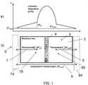
- Fig. 1billustrates a schematic top view on a portion of a flow sensor chip according to an embodiment of the present invention, and specifically on a portion of a substrate 1 of the flow sensor chip that is thinned from its backside and therefore can be considered as a membrane 3.
- the portion outside the membrane 3represents a non-thinned portion of the substrate.
- the membrane 3represents a measurement region 8 of the substrate with a low thermal conductivity which is achieved by the recess.
- the region outside the membrane 3is referred to as regular region 9 with a thermal conductivity that typically exceeds the thermal conductivity of the membrane 3.
- the basic sensor elementsare all at least partly arranged on the substrate, i.e. a heater 4, a first thermocouple 6, a second thermocouple 7 as well as a third thermocouple 5 extending along the membrane 3.
- reference 68refers to a location downstream of the heater 4
- reference 78refers to a location upstream of the heater 4, both of which locations 68 and 78 are on the membrane 3.
- a fist reference location 64is located outside the membrane 3 on the substrate downstream of the heater 4, while a second reference location 74 is located outside the membrane 3 on the substrate 1 upstream of the heater 4.
- thermocouple 6extends between the downstream location 68 and the first reference location 64
- second thermocouple 7extends between the upstream location 78 and the second reference location 74
- third thermocouple 5extends between the first reference location 64 and the second reference location 74, in the present example outside the membrane 3.
- FIG. 1aillustrates a temperature profile corresponding to the section of the flow sensor arrangement shown in FIG. 1b ) and denotes temperature differences measured by the individual thermocouples 5, 6 and 7.
- the temperatures at both sides of the heater 4 serving as reference temperatures for the first and the second thermocouple 6, 7are slightly different from each other.
- ⁇ T⁇ T down ⁇ ⁇ T up ⁇ ⁇ T comp
- Fig. 2illustrates a flow sensor arrangement in a top view according to another embodiment of the present invention.
- Fig. 3illustrates the corresponding cut along II - II in Fig. 2 .
- Both, the arrangement of Figs. 1 and 2are preferably designed as a semiconductor chip based on a silicon substrate 1, even though another semiconductor or dielectric substrate could be used as well, such as a glass substrate. It is understood, that the term substrate 1 comprises bulk material 11 as well as layers 12 deposited thereon, such as CMOS layers. A recess or opening 2 is formed in the substrate 1, e.g. by etching techniques, such that a membrane 3 is generated in the substrate 1 that extends over the recess 2.
- a heater 4extends over the membrane 3 which heater 4 is formed by three parallel conductors 4a, 4b, 4c, the two outer conductors 4a, 4c being arranged, electrically, in parallel, while the center conductor 4b (having double cross section) is in series to the conductors 4a, 4c.
- thermopile TP6comprises a plurality of first thermocouples 6 in series and is arranged downstream of the heater 4.
- a second thermopile TP7comprises a plurality of second thermocouples 7 in series and is arranged upstream of the heater 4.
- upstream and downstreamare defined with respect to a flow direction F perpendicular to a longitudinal axis of the heater 4.
- Each thermocouple TP6, TP7comprises a metal element 61, 71 (shown in continuous lines in Fig. 2 ) formed in a metal layer of the stack of layers 12 as well as a polysilicon element 62, 72 (shown in dotted lines in Fig. 2 ) formed in a polysilicon layer of the stack of layers 12.
- thermocouple TP6, TP7are interconnected at junctions 63, 73 on the membrane 3.
- the polysilicon and metal elements 62, 72 and 61, 71 of two neighboring thermocouples 6, 7are interconnected at other junctions 69, 79 which other junctions 10 are not located on the membrane 3, but over the bulk material 11 of the substrate 1.
- the other junctions 69 of the first thermopile TP6define a first reference location 64 while the other junctions 79 of the second thermopile TP7 define a second reference location 74, wherein the second reference location 74 is separated from the first reference location 64 by the membrane 3, which is also true for the embodiment of Fig. 1 .
- thermocouple 5comprising a junction 53 at the first reference location 64 and terminals 51, 52 at the second reference location 74.
- the third thermocouple 5extends between these reference locations 64 and 74 and thereby passes the membrane 3.
- the third thermocouple 5comprises of a metal element and a polysilicon element.
- thermopilescomprise elements of two different metals, or alternatively.
- one of the elementsis of n+ polysilicon and the other element is of p+ polysilicon.
- a flow of a fluid along flow direction Fcauses a distribution of heat from the heater 4 to become more asymmetric, which creates a difference of temperatures at the junctions 63 and 73 of the two thermopiles TP6, TP7.
- the other junctions 69 of the first thermopile TP6remain at a temperature of the bulk material 11 at the first reference location 64 while the other junctions 79 of the second thermopile TP7 remain at a temperature of the bulk material 11 at the second reference location 74 the temperatures of which reference locations 64, 74 may differ from each other as explained above in more detail.
- thermopiles TP6 and TP7substantially represents a sensing signal ⁇ T of the temperature difference at the first junctions 79 and 69 upstream and downstream of the heater 4 compensated by a temperature difference between the first and the second reference location 64 and 74.
- This sensing signal ⁇ Tis a measure for the mass flow of the fluid.
- an A/D-converteris provided for digitizing the sensing signal ⁇ T or yet the first, the second and the third signal.
- meansare provided for determining the sensing signal ⁇ T, which means are either embodied as hardware, as firmware or as software.
- the subject calculationcan be implemented hardwired, or by a processor, for example.
- a heater control 17is provided for controlling a current through the heater 4, and a processing unit for processing the digitized sensing signal ⁇ T, possibly including a look-up table for converting the sensing signal ⁇ T into a flow.
- the circuitry for all these elementsis integrated in the substrate 1, but it can also be formed at least in part by external components.
- thermocouplesarranged upstream and downstream from the heater. It is noted, though, that a single thermocouple can be used, which is e.g. located downstream from the heater, in case the device is designed to measure a flow in one direction only, or which extends between junctions upstream and downstream of the heater.
- each thermocouple used in the various thermopiles or alonecomprises two conductors of a different material.
- the same materialsare used for all thermocouples in order to profit from common aging properties.
- one of the materialsis a polysilicon while the other material is a metal, such as aluminum.
- all conductors of the thermocouplesare preferably manufactured from the same two layers deposited on the substrate, e.g. one being a polysilicon layer and the other one being a metal layer.
Landscapes
- Physics & Mathematics (AREA)
- Fluid Mechanics (AREA)
- General Physics & Mathematics (AREA)
- Measuring Volume Flow (AREA)
Description
- The invention relates to a flow sensor arrangement, and to a method for determining the flow of a fluid.
- Commonly used calorimetric flow sensors feature a heat source in form of a heater and spatially separated temperature sensors embedded in a thin membrane. The temperature sensors typically located upstream and downstream of the heater measure the amount of heat that is carried away by the fluid in a direct or indirect way. A thermocouple may be used as temperature sensor which thermocouple is made from two dissimilar materials which are joined at at least one junction. The junction is located on the membrane whose temperature condition is to be measured. This junction is also referred to as hot junction. Terminals of the thermocouple, or further junctions / cold junctions when connecting to other thermocouples are maintained at a constant temperature of the bulk material surrounding the membrane, for example. A difference in potential is created whenever there is a difference in temperature between the hot junction of the respective thermocouple and the corresponding cold junction, resulting in an easily measurable thermoelectric voltage. The difference between the up- and downstream thermoelectric voltage can be used as a measure for a velocity of the fluid.
- "3D modelling of a thermopile-based SOI CMOS thermal wall shear stress sensor", Falco et al., CAS 2014, IEEE, 13. October 2014, p. 277-280, refers to a wall shear stress sensor including three thermopiles, two of which are symmetrically placed aside of a heater with the hot junctions on a membrane and the cold junctions outside the membrane. The third thermopile - also referred to as central thermopile - is embedded in the membrane between the two other thermopiles. In case of a flow, a temperature gradient appears across the central thermopile resulting in a non-zero voltage that is roughly equal to a differential voltage of the lateral thermopiles.
- "A Thermopile Based SOI CMOS MEMS Wall Shear Stress Sensor", De Luca et al., CAS 2013, IEEE, vol. 1, 14. October 2013, p. 59-62, refers to a wall shear stress sensor based on a tungsten hot-film and three thermopiles. The first and second thermopiles each have hot junctions arranged on a membrane of the sensor, and cold junctions outside the membrane, while the third thermopile which is also referred to as central thermopile has both hot and cold junctions embedded in the membrane.
- According to a first aspect of the present invention, a flow sensor arrangement is provided for determining the flow of a fluid. The flow sensor arrangement comprises a substrate. A heater is arranged on or in the substrate as well as at least one first thermocouple for generating a first signal proportional to a temperature difference between a location downstream from the heater and a first reference location, and at least one second thermocouple for generating a second signal proportional to a temperature difference between a location upstream from the heater and a second reference location which second reference location is different from the first reference location. At least one third thermocouple is provided for generating a third signal proportional to a temperature difference between the first reference location and the second reference location. Finally, a sensing signal indicative of the flow of the fluid over the heater and the first and the second thermocouple is calculated dependent on the first signal, the second signal and the third signal.
- The measured thermoelectric voltage difference represented by the sensing signal is intentionally related to a temperature difference between the locations up- and downstream of the heater caused by the fluid flow. The locations up- and downstream of the heater as well as the heater itself are preferably arranged on a membrane which may be built by thinning the substrate, and in particular by thinning a bulk material of the substrate at the defined location. Preferably, the substrate comprises at least the bulk material such as silicon, and preferably in addition layers deposited thereon, such as CMOS layers. A recess may be formed in the bulk material from its back side, i.e. the side opposite from a front side the layers are arranged on. The membrane may exclusively be built from one or more of the layers in case the bulk material is completely removed in the area of the membrane, or may be built from one or more of the layers and a portion of the bulk material in case the bulk material is thinned in the region of the membrane but not completely removed. In a different embodiment, the recess is not built from the back side but from the front side of the bulk material prior to applying the layers such that by applying the layers a cavity is built between the layers forming the membrane and the bulk material.
- Hence, hot junctions of the first and the second thermocouple are placed down- and upstream of the heater on the membrane. In this context, the membrane defines an area of the substrate, also referred to as measuring region, with a thermal conductance lower than in the rest of the substrate where the bulk material is not thinned, and which region is also referred to as regular region. Terminals of the first thermocouple, or corresponding cold junctions / other junctions, are therefore preferably arranged in the regular region, i.e. outside the membrane, at a location referred to as first reference location. The same holds for terminals or corresponding cold junctions / other junctions of the second thermocouple which are preferably placed in the regular region at a second reference location, which, however, is understood to be spaced apart from the first reference location, e.g. by the membrane.
- However, in a different embodiment, all junctions of the first, second and third thermocouple may completely be arranged on the membrane, e.g. in case the membrane itself provides areas of different thermal conductance.
- It was now found that the thermoelectric voltage difference of the first and the second thermocouple may also - unintentionally - be related to a temperature difference between the first and the second reference location. There may be a number of factors influencing the temperatures at the first and the second reference location inhomogeneously and consequently may have an undesirable effect on the thermoelectric voltage difference:
- Production related membrane asymmetries are often characterized on wafer level. This offset calibration process, which potentially takes into account a temperature dependence of the membrane asymmetry, is very important to achieve a high accuracy of the final flow sensor arrangement. But for the final application diced sensor chips mounted on a PCB or a lead frame, etc. may individually be assembled in a flow-housing. Surrounding thermal sources and sinks may change significantly by a transition from the flow sensor chip embedded in a wafer composite to the diced and individually assembled flow sensor chips. Thereby, a temperature difference between the thermocouple cold junctions might also change. And therefore, an accurate calibration may require the determination and correction of such changing thermal differences between the cold junctions.
- The activity of energy dissipating elements integrated in the bulk material surrounding the membrane, such as an electrical circuitry measuring and processing the voltage difference signal, may also affect the temperature difference between the cold junctions, which is the case for diced flow sensor chips as well as for flow sensor chips in the wafer composite.
- Hence, presently a flow sensor arrangement is proposed, in which a temperature difference between the first and the second reference locations is measured by at least one third thermocouple to achieve an improved calibration accuracy for the measured thermoelectric voltage difference signal. In brief, it is proposed to integrate a third thermocouple in or on the substrate with the respective two junctions in close proximity to the cold junctions of the up- and downstream thermocouples. A signal stemming from this third thermocouple is used for compensating the sensing signal for temperature differences between these two reference locations.
- Each of the first, second and third thermocouple preferably comprises one of:
- a junction connecting two metal elements of a different material;
- a junction connecting two polysilicon elements of different doping, and preferably wherein one of the polysilicon elements comprises an n+ doping while the other polysilicon element comprises a p+ doping;
- a junction connecting a metal element and a polysilicon element, e.g. of n+ or p+ doping.
- Preferably, each of the first, second and third thermocouple comprises the same material composition. In the case of thermopiles comprising multiple thermocouples, it is preferred that all thermocouples are made from the same material composition.
- Preferably, the first thermocouple is embodied in a first thermopile with multiple first thermocouples comprising junctions arranged at the location downstream from the heater and other junctions arranged at the first reference location by connecting the terminals of adjacent first thermocouples.
- Preferably, the second thermocouple is embodied in a second thermopile with multiple second thermocouples comprising junctions arranged at the location upstream from the heater and other junctions arranged at the second reference location by connecting the terminals of adjacent second thermocouples.
- Preferably, the third thermocouple is embodied in a third thermopile with multiple third thermocouples comprising junctions arranged at one of the first reference location and the second reference location and other junctions arranged at the second reference location or first reference location respectively by connecting the terminals of adjacent third thermocouples.
- Preferably, the heater comprises one of a metal element and a polysilicon element, e.g. of n+ or p+ doping. Preferably, the heater is made from the same material composition as are the thermocouples, i.e. the heater is made from metal in case both of the thermocouple elements are made from metal, or is made from polysilicon in case both of the thermocouple elements are made from polysilicon. Preferably, for both, the heater and a thermocouple, in case of a metal element, the metal element is formed in a metal layer of a stack of layers, such as CMOS layers arranged a bulk material of the substrate. Preferably, in case of a polysilicon element, the polysilicon element is formed in a polysilicon layer of the stack of layers. Hence, it is preferred that the heater and the thermocouples are made compatible to CMOS processing.
- According to a further aspect of the present invention, a method according to claim 18 is provided for determining the flow of a fluid. A substrate is provided with a heater, at least one first thermocouple, at least one second thermocouple, and at least one third thermocouple arranged therein or thereon. By the at least one first thermocouple a first signal is measured proportional to a temperature difference between a location downstream from the heater and a first reference location. A second signal proportional to a temperature difference between a location upstream from the heater and a second reference location which second reference location is different from the first reference location is measured by the at least one second thermocouple. A third signal proportional to a temperature difference between the first reference location and the second reference location is measured by the at least one third thermocouple. The flow of the fluid over the heater and the first and the second thermocouple, at least their hot junctions, is determined dependent on the first signal, the second signal and the third signal.
- Further advantageous embodiments are illustrated in more detail in the dependent claims.
- Further advantages and advantageous embodiments are illustrated in more detail in the following description. This description makes reference to the attached figures, which illustrate:
Fig. 1 a top view on a section of a flow sensor arrangement according to a preferred embodiment of the present invention in diagram b) and a corresponding temperature profile in diagram a);Fig. 2 a top view on a flow sensor arrangement according to another preferred embodiment of the present invention, andFig. 3 a schematic sectional view of the flow sensor arrangement along line II-II ofFig. 2 .Fig. 1b ) illustrates a schematic top view on a portion of a flow sensor chip according to an embodiment of the present invention, and specifically on a portion of a substrate 1 of the flow sensor chip that is thinned from its backside and therefore can be considered as amembrane 3. The portion outside themembrane 3 represents a non-thinned portion of the substrate. Owed to this structure, themembrane 3 represents ameasurement region 8 of the substrate with a low thermal conductivity which is achieved by the recess. In contrast, the region outside themembrane 3 is referred to asregular region 9 with a thermal conductivity that typically exceeds the thermal conductivity of themembrane 3.- The basic sensor elements are all at least partly arranged on the substrate, i.e. a
heater 4, afirst thermocouple 6, asecond thermocouple 7 as well as athird thermocouple 5 extending along themembrane 3. Under the assumption that the fluid flows from left to right inFig. 1b ),reference 68 refers to a location downstream of theheater 4,reference 78 refers to a location upstream of theheater 4, both of whichlocations membrane 3. Afist reference location 64 is located outside themembrane 3 on the substrate downstream of theheater 4, while asecond reference location 74 is located outside themembrane 3 on the substrate 1 upstream of theheater 4. Hence thefirst thermocouple 6 extends between thedownstream location 68 and thefirst reference location 64, thesecond thermocouple 7 extends between theupstream location 78 and thesecond reference location 74, and thethird thermocouple 5 extends between thefirst reference location 64 and thesecond reference location 74, in the present example outside themembrane 3. FIG. 1a ) illustrates a temperature profile corresponding to the section of the flow sensor arrangement shown inFIG. 1b ) and denotes temperature differences measured by theindividual thermocouples heater 4 serving as reference temperatures for the first and thesecond thermocouple - For further reference, the following variables are used:
- Tcomp_down: Temperature of the substrate 1 at the
first reference location 64, i.e. on the downstream side; - Tcomp_up: Temperature of the substrate 1 at the
second reference location 74, i.e. on the upstream side; - Tmembrane_down: Temperature of the
membrane 3 at thedownstream location 68, - Tmembrane_up: Temperature of the
membrane 3 at theupstream location 78. - Hence, it follows that the
first thermocouple 6 measures the following first signal ΔTdown:
- The
second thermocouple 7 measures the following second signal ΔTup:
- And the
third thermocouple 5 measures the following third signal ΔTup:
- Finally, means not shown in
Fig. 1 are provided for determining a sensing signal ΔT which is indicative of the flow of the fluid passing the structure as illustrated inFig. 1b ):
- Of course, in case there is no difference in bulk temperatures Tcomp_up = Tcomp_down there is no compensation required and Tcomp contributes by the value zero to the sensing signal ΔT.
Fig. 2 illustrates a flow sensor arrangement in a top view according to another embodiment of the present invention.Fig. 3 illustrates the corresponding cut along II - II inFig. 2 .- Both, the arrangement of
Figs. 1 and2 are preferably designed as a semiconductor chip based on a silicon substrate 1, even though another semiconductor or dielectric substrate could be used as well, such as a glass substrate. It is understood, that the term substrate 1 comprises bulk material 11 as well as layers 12 deposited thereon, such as CMOS layers. A recess oropening 2 is formed in the substrate 1, e.g. by etching techniques, such that amembrane 3 is generated in the substrate 1 that extends over therecess 2. - In
Figs. 2 and 3 , aheater 4 extends over themembrane 3 whichheater 4 is formed by threeparallel conductors outer conductors center conductor 4b (having double cross section) is in series to theconductors - A first thermopile TP6 comprises a plurality of
first thermocouples 6 in series and is arranged downstream of theheater 4. A second thermopile TP7 comprises a plurality ofsecond thermocouples 7 in series and is arranged upstream of theheater 4. The terms "upstream" and "downstream" are defined with respect to a flow direction F perpendicular to a longitudinal axis of theheater 4. Each thermocouple TP6, TP7 comprises a metal element 61, 71 (shown in continuous lines inFig. 2 ) formed in a metal layer of the stack of layers 12 as well as a polysilicon element 62, 72 (shown in dotted lines inFig. 2 ) formed in a polysilicon layer of the stack of layers 12. The metal andpolysilicon elements junctions membrane 3. The polysilicon andmetal elements neighboring thermocouples other junctions membrane 3, but over the bulk material 11 of the substrate 1. In particular, theother junctions 69 of the first thermopile TP6 define afirst reference location 64 while theother junctions 79 of the second thermopile TP7 define asecond reference location 74, wherein thesecond reference location 74 is separated from thefirst reference location 64 by themembrane 3, which is also true for the embodiment ofFig. 1 . - In addition, a
third thermocouple 5 is provided comprising ajunction 53 at thefirst reference location 64 andterminals 51, 52 at thesecond reference location 74. Thethird thermocouple 5 extends between thesereference locations membrane 3. Preferably, thethird thermocouple 5 comprises of a metal element and a polysilicon element. - In an alternate embodiment, all of the first, second and third thermopiles comprise elements of two different metals, or alternatively. In a further variant one of the elements is of n+ polysilicon and the other element is of p+ polysilicon.
- A flow of a fluid along flow direction F causes a distribution of heat from the
heater 4 to become more asymmetric, which creates a difference of temperatures at thejunctions other junctions 69 of the first thermopile TP6 remain at a temperature of the bulk material 11 at thefirst reference location 64 while theother junctions 79 of the second thermopile TP7 remain at a temperature of the bulk material 11 at thesecond reference location 74 the temperatures of whichreference locations - Hence, a difference of voltages from the thermopiles TP6 and TP7 (or any value proportional thereto) and the
third thermocouple 5 substantially represents a sensing signal ΔT of the temperature difference at thefirst junctions heater 4 compensated by a temperature difference between the first and thesecond reference location - Generally, it is preferred that an A/D-converter is provided for digitizing the sensing signal ΔT or yet the first, the second and the third signal. Generally, means are provided for determining the sensing signal ΔT, which means are either embodied as hardware, as firmware or as software. Hence, in a preferred embodiment, the subject calculation can be implemented hardwired, or by a processor, for example. Preferably, a heater control 17 is provided for controlling a current through the
heater 4, and a processing unit for processing the digitized sensing signal ΔT, possibly including a look-up table for converting the sensing signal ΔT into a flow. Advantageously, the circuitry for all these elements is integrated in the substrate 1, but it can also be formed at least in part by external components. - The embodiments shown so far comprise two thermocouples arranged upstream and downstream from the heater. It is noted, though, that a single thermocouple can be used, which is e.g. located downstream from the heater, in case the device is designed to measure a flow in one direction only, or which extends between junctions upstream and downstream of the heater.
- It is noted that in the embodiments described above, each thermocouple used in the various thermopiles or alone comprises two conductors of a different material. Advantageously, the same materials are used for all thermocouples in order to profit from common aging properties. Advantageously, one of the materials is a polysilicon while the other material is a metal, such as aluminum. In addition, all conductors of the thermocouples are preferably manufactured from the same two layers deposited on the substrate, e.g. one being a polysilicon layer and the other one being a metal layer.


Claims (19)
- Flow sensor arrangement for determining the flow of a fluid, comprising
a substrate (1), and arranged therein or thereon:- a heater (4),- at least one first thermocouple (6) for generating a first signal (ΔTdown) proportional to a temperature difference between a location downstream (68) from the heater (4) and a first reference location (64), wherein the first thermocouple (6) comprises a hot junction arranged at the location downstream from the heater (4) and a cold junction arranged at the first reference location (64),- at least one second thermocouple (7) for generating a second signal (ΔTup) proportional to a temperature difference between a location upstream (78) from the heater (4) and a second reference location (74) which second reference location (74) is different from the first reference location (64), wherein the second thermocouple (7) comprises a hot junction at the location upstream from the heater (4) and a cold junction arranged at the second reference location (74),- at least one third thermocouple (5) for generating a third signal (ΔTcomp) proportional to a temperature difference between the first reference location (64) and the second reference location (74), means for determining a sensing signal (ΔT) indicative of the flow of the fluid over the heater (4) and the first and the second thermocouple (6, 7) dependent on the first signal (ΔTdown), the second signal (ΔTup) and the third signal (ΔTcomp). - The flow sensor arrangement according to claim 1,
wherein the determination means is adapted to determine a difference between the first and the second signal (ΔTdown, ΔTup) and to adjust the difference by subtracting the third signal (ΔTcomp) therefrom for compensating for different temperatures at the first and the second reference location (64, 74). - The flow sensor arrangement according to claim 1 or claim 2,
wherein the determination means (10) is adapted to subtract the second signal (ΔTup) and the third signal (ΔTcomp) from the first signal (ΔTdown). - The flow sensor arrangement according to any of the preceding claims,
comprising a first thermopile (TP6) with multiple first thermocouples (6) comprising hot junctions (63) arranged at the location downstream (68) from the heater (4) and cold junctions (69) arranged at the first reference location (64) by connecting the terminals (61, 62) of adjacent first thermocouples (6), and
comprising a second thermopile (TP7) with multiple second thermocouples (7) comprising hot junctions (73) arranged at the location upstream (78) from the heater (4) and cold junctions (79) arranged at the second reference location (74) by connecting the terminals (71, 72) of adjacent second thermocouples (7). - The flow sensor arrangement according to any one of the preceding claims,
wherein the third thermocouple (5) comprises a hot junction (53) arranged at the first reference location (64) and a cold junction (51, 52) arranged at the second reference location (74), or
wherein the third thermocouple (5) comprises a hot junction (53) arranged at the second reference location (74) and a cold junction (51, 52) arranged at the first reference location (64). - The flow sensor arrangement according to claim 5,
comprising a third thermopile with multiple third thermocouples (5) comprising hot junctions (53) arranged at one of the first reference location (64) and the second reference location (74) and cold junctions arranged at the second reference location (74) or first reference location (64) respectively by connecting the terminals (51, 52) of adjacent third thermocouples (5). - The flow sensor arrangement according to any of the preceding claims,
wherein the substrate (1) comprises a measuring region (8) and a regular region (9),
wherein a thermal conductance in the measuring region (8) is lower than a thermal conductance in the regular region (9), and
wherein the heater (4), the downstream location (68) and the upstream location (78) are arranged in the measuring region (8) while the first reference location (64) and the second reference location (74) are arranged in the regular region (9). - The flow sensor arrangement according to claim 7,
comprising a recess (2) in the substrate (1) thereby defining a membrane (3) extending over the recess (2) respectively,
wherein the measuring region (8) is defined by the membrane (3) and the regular region (9) is defined outside the measuring region (8). - The flow sensor arrangement according to claim 7 or claim 8,
wherein the one or more hot junctions (63) of the first one or more thermocouples (6) and the one or more hot junctions (73) of the one or more second thermocouples (7) are arranged in the measuring region (8) while the one or more cold junctions (69) of the one or more first thermocouples (6) and the one or more cold junctions (79) of the one or more second thermocouples (7) are arranged in the regular region (9). - The flow sensor arrangement according to claim 5 in combination with claim 7 or claim 8,
wherein the one or more hot junctions (53) and the one or more cold junctions of the one or more third thermocouples (5) are all arranged in the regular region (9). - The flow sensor arrangement according to any one of the preceding claims 7 to 10,
wherein the one or more third thermocouples (5) extend from the regular region (9) over the measurement region (8) into the regular region (9). - The flow sensor arrangement according to any of the preceding claims 7 to 10,
wherein the one or more third thermocouples (5) exclusively extend over the regular region (9). - The flow sensor arrangement according to claim 1,
comprising a membrane (3) built by thinning the substrate (1),
wherein the heater (4) is arranged on the membrane (3),
wherein all junctions of the first, second and third thermocouple (6,7,5) are completely arranged on the membrane (3),
wherein the membrane (3) provides areas of different thermal conductance. - The flow sensor arrangement according to any of the preceding claims,
wherein the determination means is integrated into the substrate (1), and
preferably wherein the determination means is hardwired logic. - The flow sensor arrangement according to any of the preceding claims,
wherein each of the first, second and third thermocouple (6, 7, 5) comprises one of:- a junction connecting two metal elements of different material;- a junction connecting two polysilicon elements of different doping, and preferably wherein one of the polysilicon elements comprises an n+ doping while the other polysilicon element comprises a p+ doping;- a junction connecting a metal element and a polysilicon element;and preferably wherein all the first, second and third thermocouples (6, 7, 5) comprise the same material composition. - The flow sensor arrangement according to any of the preceding claims,
wherein the heater (4) comprises one of a metal element and a polysilicon element,
and preferably wherein the heater (4) comprises a metal element in case both of the elements of at least one of the first, second or third thermocouple (6, 7, 5) comprises metal, or comprises polysilicon in case both of the elements of at least one of the first, second or third thermocouple (6, 7, 5) comprises polysilicon. - The flow sensor arrangement according to any of the preceding claims,
wherein all of the heater (4) and the first, second and third thermocouple (6, 7, 5) are formed of one or more metal layers or polysilicon layers of a stack of CMOS layers arranged on a bulk material (11) of the substrate (1). - Method for determining the flow of a fluid, comprising- providing a substrate (1) with a heater (4), at least one first thermocouple (6), at least one second thermocouple (7), and at least one third thermocouple (5) arranged therein or thereon,- measuring by the at least one first thermocouple (6) a first signal (ΔTdown) proportional to a temperature difference between a location downstream (68) from the heater (4) and a first reference location (64), wherein the first thermocouple (6) comprises a hot junction arranged at the location downstream from the heater (4) and a cold junction arranged at the first reference location (64),- measuring by the at least one second thermocouple (7) a second signal (ΔTup) proportional to a temperature difference between a location upstream (78) from the heater (4) and a second reference location (74) which second reference location (74) is different from the first reference location (64), wherein the second thermocouple (7) comprises a hot junction at the location upstream from the heater (4) and a cold junction arranged at the second reference location (74),- measuring by the at least one third thermocouple (5) a third signal (ΔTcomp) proportional to a temperature difference between the first reference location (64) and the second reference location (74), and- determining the flow of the fluid over the heater (4) and the first and the second thermocouple (6, 7) dependent on the first signal (ΔTdown), the second signal (ΔTup) and the third signal (ΔTcomp).
- Method according to claim 18,
which steps are performed during a calibration routine of a flow sensor arrangement comprising the substrate (1), the heater (4) and the first, second and third thermocouple (6, 7, 5).
Priority Applications (2)
| Application Number | Priority Date | Filing Date | Title |
|---|---|---|---|
| EP14004363.9AEP2930475B1 (en) | 2014-12-22 | 2014-12-22 | Flow sensor arrangement |
| US14/976,799US10094691B2 (en) | 2014-12-22 | 2015-12-21 | Flow sensor arrangement |
Applications Claiming Priority (1)
| Application Number | Priority Date | Filing Date | Title |
|---|---|---|---|
| EP14004363.9AEP2930475B1 (en) | 2014-12-22 | 2014-12-22 | Flow sensor arrangement |
Publications (2)
| Publication Number | Publication Date |
|---|---|
| EP2930475A1 EP2930475A1 (en) | 2015-10-14 |
| EP2930475B1true EP2930475B1 (en) | 2017-11-15 |
Family
ID=52133787
Family Applications (1)
| Application Number | Title | Priority Date | Filing Date |
|---|---|---|---|
| EP14004363.9AActiveEP2930475B1 (en) | 2014-12-22 | 2014-12-22 | Flow sensor arrangement |
Country Status (2)
| Country | Link |
|---|---|
| US (1) | US10094691B2 (en) |
| EP (1) | EP2930475B1 (en) |
Families Citing this family (11)
| Publication number | Priority date | Publication date | Assignee | Title |
|---|---|---|---|---|
| DE102012001060A1 (en)* | 2011-10-24 | 2013-04-25 | Hydrometer Gmbh | Method for correcting offset drift effects of a thermal measuring device, thermal measuring device and gas flow meter |
| GB2558896B (en) | 2017-01-17 | 2019-10-09 | Cambridge Entpr Ltd | A single membane flow-pressure sensing device |
| US10593826B2 (en) | 2018-03-28 | 2020-03-17 | Cambridge Gan Devices Limited | Infra-red devices |
| US11067422B2 (en) | 2018-03-28 | 2021-07-20 | Cambridge Gan Devices Limited | Thermal fluid flow sensor |
| EP3671139A1 (en) | 2018-12-20 | 2020-06-24 | Sensirion AG | Detection of contaminations on a sensing surface of a thermal sensor |
| US10775217B1 (en)* | 2019-04-19 | 2020-09-15 | Honeywell International Inc. | Thermophile-based flow sensing device |
| US11073415B2 (en) | 2019-10-21 | 2021-07-27 | Flusso Limited | Thermal fluid flow sensor having a dielectric membrane comprising discontinuities between the heating element and an edge |
| CA3103598A1 (en) | 2020-12-21 | 2022-06-21 | Federico Torriano | ELECTRONIC FLOW METER WITH HEAT BALANCE |
| US12013270B2 (en) | 2021-02-25 | 2024-06-18 | Flusso Limited | Flow sensor |
| JP7597304B2 (en) | 2021-03-11 | 2024-12-10 | Mmiセミコンダクター株式会社 | Flow Sensor Chip |
| EP4372324B1 (en) | 2022-11-15 | 2025-06-18 | Flusso Limited | Method and controller for controlling a fluid-flow sensor |
Family Cites Families (34)
| Publication number | Priority date | Publication date | Assignee | Title |
|---|---|---|---|---|
| US3042786A (en) | 1958-08-14 | 1962-07-03 | American Brake Shoe Co | Electrical heating apparatus |
| US4651564A (en) | 1982-09-30 | 1987-03-24 | Honeywell Inc. | Semiconductor device |
| US4672997A (en) | 1984-10-29 | 1987-06-16 | Btu Engineering Corporation | Modular, self-diagnostic mass-flow controller and system |
| US4623266A (en) | 1985-09-24 | 1986-11-18 | Rosemount Inc. | Cold junction compensation for thermocouple |
| US5288147A (en)* | 1992-11-09 | 1994-02-22 | Ta Instruments, Inc. | Thermopile differential thermal analysis sensor |
| DE4418207C1 (en) | 1994-05-25 | 1995-06-22 | Siemens Ag | Thermal sensor or actuator in semiconductor material |
| AU3162297A (en) | 1996-06-26 | 1998-01-14 | Simon Fraser University | Accelerometer without proof mass |
| JPH11264332A (en) | 1997-12-17 | 1999-09-28 | Hitachi Ltd | Air flow meter with electronically controlled throttle body |
| US6545334B2 (en) | 1997-12-19 | 2003-04-08 | Imec Vzw | Device and a method for thermal sensing |
| NL1008665C1 (en) | 1998-03-20 | 1999-09-21 | Berkin Bv | Medium flow meter. |
| JP3470881B2 (en) | 1999-04-19 | 2003-11-25 | 矢崎総業株式会社 | Micro flow sensor |
| JP4050857B2 (en) | 1999-04-27 | 2008-02-20 | 矢崎総業株式会社 | Fluid discrimination device and flow rate measuring device |
| EP1065475B1 (en) | 1999-05-31 | 2017-07-12 | Sensirion Holding AG | Method of measuring a gas flow |
| JP3468727B2 (en) | 1999-09-24 | 2003-11-17 | 株式会社日立製作所 | Thermal air flow meter |
| CH695166A5 (en) | 2000-04-25 | 2005-12-30 | Sensirion Ag | Method and apparatus for measuring the flow of a liquid. |
| JP2002048615A (en) | 2000-08-02 | 2002-02-15 | Tokyo Gas Co Ltd | Flow meter using heat flow sensor |
| JP3658321B2 (en) | 2000-12-28 | 2005-06-08 | オムロン株式会社 | Flow sensor and manufacturing method thereof |
| JP3945385B2 (en)* | 2002-11-15 | 2007-07-18 | オムロン株式会社 | Flow sensor and flow measurement method |
| JP3718198B2 (en) | 2003-02-26 | 2005-11-16 | 株式会社日立製作所 | Flow sensor |
| NL1025617C2 (en) | 2003-05-13 | 2004-11-18 | Berkin Bv | Mass flow meter. |
| JP4292026B2 (en) | 2003-05-30 | 2009-07-08 | 株式会社日立製作所 | Thermal flow sensor |
| US7234864B2 (en) | 2004-09-30 | 2007-06-26 | Rockwell Automation Technologies, Inc. | Measurement of multi-channel cold junction temperature |
| EP1840536B1 (en) | 2006-03-31 | 2011-01-19 | Sensirion Holding AG | Flow sensor with flow-adaptable analog-digital-converter |
| EP1840535B1 (en)* | 2006-03-31 | 2011-01-12 | Sensirion Holding AG | Flow sensor with thermocouples |
| EP1965179B1 (en) | 2007-02-28 | 2017-04-12 | Sensirion Holding AG | Flow detector device with self check |
| KR100931702B1 (en)* | 2007-11-20 | 2009-12-14 | 재단법인서울대학교산학협력재단 | Thermopile Flow Rate Sensor |
| WO2009119116A1 (en) | 2008-03-27 | 2009-10-01 | パナソニック株式会社 | Environment temperature measuring method, liquid sample measuring method, and measuring device |
| US8140294B2 (en) | 2009-06-05 | 2012-03-20 | Roche Diagnostics Operations, Inc. | Temperature estimations in a blood glucose measuring device |
| US20110119018A1 (en) | 2009-11-19 | 2011-05-19 | Sony Ericsson Mobile Communications Ab | Estimation of ambient temperature |
| EP2392898B1 (en) | 2010-06-04 | 2017-12-13 | Sensirion AG | Sensor system |
| US20120065923A1 (en) | 2010-09-14 | 2012-03-15 | General Electric Company | Integrated cold junction compensation circuit for thermocouple connections |
| GB201116481D0 (en) | 2011-09-26 | 2011-11-09 | Cellnovo Ltd | Monitoring devices |
| EP2682715B1 (en) | 2012-07-02 | 2015-03-11 | Sensirion AG | Portable electronic device |
| EP2808650B1 (en) | 2013-05-31 | 2017-03-22 | Sensirion AG | Portable electronic device |
- 2014
- 2014-12-22EPEP14004363.9Apatent/EP2930475B1/enactiveActive
- 2015
- 2015-12-21USUS14/976,799patent/US10094691B2/enactiveActive
Non-Patent Citations (1)
| Title |
|---|
| None* |
Also Published As
| Publication number | Publication date |
|---|---|
| US20160216144A1 (en) | 2016-07-28 |
| EP2930475A1 (en) | 2015-10-14 |
| US10094691B2 (en) | 2018-10-09 |
Similar Documents
| Publication | Publication Date | Title |
|---|---|---|
| EP2930475B1 (en) | Flow sensor arrangement | |
| GB2558895B (en) | A thermal fluid flow sensor | |
| US7490511B2 (en) | Flow sensor with flow-adaptable analog-digital-converter | |
| JP5874117B2 (en) | Thermal conductivity sensor that calibrates the effects of fluid temperature and type, thermal flow sensor and thermal pressure sensor using the same | |
| CN101680788B (en) | Thermal Flow Meter | |
| EP3062077B1 (en) | Multi-sensor assembly | |
| US10175120B2 (en) | Internal temperature measurement method and internal temperature measurement device | |
| US11639864B2 (en) | Flow sensor | |
| US12078519B2 (en) | Thermopile-based flow sensing device | |
| JP6350212B2 (en) | Internal temperature measuring device | |
| US10564046B2 (en) | Internal temperature measuring apparatus and temperature difference measuring module | |
| US20160011031A1 (en) | Hot-Type Fluid Measurement Device | |
| EP3404373B1 (en) | Flow sensor with thermocouples | |
| EP1873499A1 (en) | Thermal flow sensor for high flow velocities | |
| CN107300425A (en) | A kind of temperature sensor and thermometry | |
| US20240157051A1 (en) | Method and controller for controlling a fluid-flow sensor | |
| Cerimovic et al. | Bidirectional micromachined flow sensor featuring a hot film made of amorphous germanium | |
| EP4372325B1 (en) | Method and controller for controlling a fluid-flow sensor | |
| EP4372324B1 (en) | Method and controller for controlling a fluid-flow sensor | |
| EP4549895A1 (en) | Thermal sensor array device, method of measuring a temperature gradient and method of measuring a temperature | |
| US11927492B2 (en) | Sensor and a system | |
| JPS5923369B2 (en) | Zero-level heat flow meter | |
| US11703399B2 (en) | Surface mount temperature measurement | |
| JP2018141664A (en) | Flow sensor |
Legal Events
| Date | Code | Title | Description |
|---|---|---|---|
| PUAI | Public reference made under article 153(3) epc to a published international application that has entered the european phase | Free format text:ORIGINAL CODE: 0009012 | |
| AK | Designated contracting states | Kind code of ref document:A1 Designated state(s):AL AT BE BG CH CY CZ DE DK EE ES FI FR GB GR HR HU IE IS IT LI LT LU LV MC MK MT NL NO PL PT RO RS SE SI SK SM TR | |
| AX | Request for extension of the european patent | Extension state:BA ME | |
| 17P | Request for examination filed | Effective date:20160407 | |
| RBV | Designated contracting states (corrected) | Designated state(s):AL AT BE BG CH CY CZ DE DK EE ES FI FR GB GR HR HU IE IS IT LI LT LU LV MC MK MT NL NO PL PT RO RS SE SI SK SM TR | |
| STAA | Information on the status of an ep patent application or granted ep patent | Free format text:STATUS: EXAMINATION IS IN PROGRESS | |
| 17Q | First examination report despatched | Effective date:20161111 | |
| GRAP | Despatch of communication of intention to grant a patent | Free format text:ORIGINAL CODE: EPIDOSNIGR1 | |
| STAA | Information on the status of an ep patent application or granted ep patent | Free format text:STATUS: GRANT OF PATENT IS INTENDED | |
| INTG | Intention to grant announced | Effective date:20170608 | |
| GRAS | Grant fee paid | Free format text:ORIGINAL CODE: EPIDOSNIGR3 | |
| GRAJ | Information related to disapproval of communication of intention to grant by the applicant or resumption of examination proceedings by the epo deleted | Free format text:ORIGINAL CODE: EPIDOSDIGR1 | |
| GRAL | Information related to payment of fee for publishing/printing deleted | Free format text:ORIGINAL CODE: EPIDOSDIGR3 | |
| STAA | Information on the status of an ep patent application or granted ep patent | Free format text:STATUS: EXAMINATION IS IN PROGRESS | |
| GRAR | Information related to intention to grant a patent recorded | Free format text:ORIGINAL CODE: EPIDOSNIGR71 | |
| STAA | Information on the status of an ep patent application or granted ep patent | Free format text:STATUS: GRANT OF PATENT IS INTENDED | |
| INTC | Intention to grant announced (deleted) | ||
| GRAA | (expected) grant | Free format text:ORIGINAL CODE: 0009210 | |
| STAA | Information on the status of an ep patent application or granted ep patent | Free format text:STATUS: THE PATENT HAS BEEN GRANTED | |
| INTG | Intention to grant announced | Effective date:20170928 | |
| AK | Designated contracting states | Kind code of ref document:B1 Designated state(s):AL AT BE BG CH CY CZ DE DK EE ES FI FR GB GR HR HU IE IS IT LI LT LU LV MC MK MT NL NO PL PT RO RS SE SI SK SM TR | |
| REG | Reference to a national code | Ref country code:CH Ref legal event code:EP Ref country code:GB Ref legal event code:FG4D Ref country code:AT Ref legal event code:REF Ref document number:946734 Country of ref document:AT Kind code of ref document:T Effective date:20171115 | |
| REG | Reference to a national code | Ref country code:IE Ref legal event code:FG4D | |
| REG | Reference to a national code | Ref country code:DE Ref legal event code:R096 Ref document number:602014017103 Country of ref document:DE | |
| REG | Reference to a national code | Ref country code:NL Ref legal event code:MP Effective date:20171115 | |
| REG | Reference to a national code | Ref country code:LT Ref legal event code:MG4D | |
| REG | Reference to a national code | Ref country code:AT Ref legal event code:MK05 Ref document number:946734 Country of ref document:AT Kind code of ref document:T Effective date:20171115 | |
| PG25 | Lapsed in a contracting state [announced via postgrant information from national office to epo] | Ref country code:SE Free format text:LAPSE BECAUSE OF FAILURE TO SUBMIT A TRANSLATION OF THE DESCRIPTION OR TO PAY THE FEE WITHIN THE PRESCRIBED TIME-LIMIT Effective date:20171115 Ref country code:LT Free format text:LAPSE BECAUSE OF FAILURE TO SUBMIT A TRANSLATION OF THE DESCRIPTION OR TO PAY THE FEE WITHIN THE PRESCRIBED TIME-LIMIT Effective date:20171115 Ref country code:NO Free format text:LAPSE BECAUSE OF FAILURE TO SUBMIT A TRANSLATION OF THE DESCRIPTION OR TO PAY THE FEE WITHIN THE PRESCRIBED TIME-LIMIT Effective date:20180215 Ref country code:FI Free format text:LAPSE BECAUSE OF FAILURE TO SUBMIT A TRANSLATION OF THE DESCRIPTION OR TO PAY THE FEE WITHIN THE PRESCRIBED TIME-LIMIT Effective date:20171115 Ref country code:ES Free format text:LAPSE BECAUSE OF FAILURE TO SUBMIT A TRANSLATION OF THE DESCRIPTION OR TO PAY THE FEE WITHIN THE PRESCRIBED TIME-LIMIT Effective date:20171115 Ref country code:NL Free format text:LAPSE BECAUSE OF FAILURE TO SUBMIT A TRANSLATION OF THE DESCRIPTION OR TO PAY THE FEE WITHIN THE PRESCRIBED TIME-LIMIT Effective date:20171115 | |
| PG25 | Lapsed in a contracting state [announced via postgrant information from national office to epo] | Ref country code:HR Free format text:LAPSE BECAUSE OF FAILURE TO SUBMIT A TRANSLATION OF THE DESCRIPTION OR TO PAY THE FEE WITHIN THE PRESCRIBED TIME-LIMIT Effective date:20171115 Ref country code:LV Free format text:LAPSE BECAUSE OF FAILURE TO SUBMIT A TRANSLATION OF THE DESCRIPTION OR TO PAY THE FEE WITHIN THE PRESCRIBED TIME-LIMIT Effective date:20171115 Ref country code:RS Free format text:LAPSE BECAUSE OF FAILURE TO SUBMIT A TRANSLATION OF THE DESCRIPTION OR TO PAY THE FEE WITHIN THE PRESCRIBED TIME-LIMIT Effective date:20171115 Ref country code:BG Free format text:LAPSE BECAUSE OF FAILURE TO SUBMIT A TRANSLATION OF THE DESCRIPTION OR TO PAY THE FEE WITHIN THE PRESCRIBED TIME-LIMIT Effective date:20180215 Ref country code:AT Free format text:LAPSE BECAUSE OF FAILURE TO SUBMIT A TRANSLATION OF THE DESCRIPTION OR TO PAY THE FEE WITHIN THE PRESCRIBED TIME-LIMIT Effective date:20171115 Ref country code:GR Free format text:LAPSE BECAUSE OF FAILURE TO SUBMIT A TRANSLATION OF THE DESCRIPTION OR TO PAY THE FEE WITHIN THE PRESCRIBED TIME-LIMIT Effective date:20180216 | |
| PG25 | Lapsed in a contracting state [announced via postgrant information from national office to epo] | Ref country code:SK Free format text:LAPSE BECAUSE OF FAILURE TO SUBMIT A TRANSLATION OF THE DESCRIPTION OR TO PAY THE FEE WITHIN THE PRESCRIBED TIME-LIMIT Effective date:20171115 Ref country code:CZ Free format text:LAPSE BECAUSE OF FAILURE TO SUBMIT A TRANSLATION OF THE DESCRIPTION OR TO PAY THE FEE WITHIN THE PRESCRIBED TIME-LIMIT Effective date:20171115 Ref country code:CY Free format text:LAPSE BECAUSE OF FAILURE TO SUBMIT A TRANSLATION OF THE DESCRIPTION OR TO PAY THE FEE WITHIN THE PRESCRIBED TIME-LIMIT Effective date:20171115 Ref country code:EE Free format text:LAPSE BECAUSE OF FAILURE TO SUBMIT A TRANSLATION OF THE DESCRIPTION OR TO PAY THE FEE WITHIN THE PRESCRIBED TIME-LIMIT Effective date:20171115 Ref country code:DK Free format text:LAPSE BECAUSE OF FAILURE TO SUBMIT A TRANSLATION OF THE DESCRIPTION OR TO PAY THE FEE WITHIN THE PRESCRIBED TIME-LIMIT Effective date:20171115 | |
| REG | Reference to a national code | Ref country code:DE Ref legal event code:R097 Ref document number:602014017103 Country of ref document:DE | |
| PG25 | Lapsed in a contracting state [announced via postgrant information from national office to epo] | Ref country code:SM Free format text:LAPSE BECAUSE OF FAILURE TO SUBMIT A TRANSLATION OF THE DESCRIPTION OR TO PAY THE FEE WITHIN THE PRESCRIBED TIME-LIMIT Effective date:20171115 Ref country code:RO Free format text:LAPSE BECAUSE OF FAILURE TO SUBMIT A TRANSLATION OF THE DESCRIPTION OR TO PAY THE FEE WITHIN THE PRESCRIBED TIME-LIMIT Effective date:20171115 Ref country code:IT Free format text:LAPSE BECAUSE OF FAILURE TO SUBMIT A TRANSLATION OF THE DESCRIPTION OR TO PAY THE FEE WITHIN THE PRESCRIBED TIME-LIMIT Effective date:20171115 Ref country code:PL Free format text:LAPSE BECAUSE OF FAILURE TO SUBMIT A TRANSLATION OF THE DESCRIPTION OR TO PAY THE FEE WITHIN THE PRESCRIBED TIME-LIMIT Effective date:20171115 | |
| REG | Reference to a national code | Ref country code:IE Ref legal event code:MM4A | |
| PLBE | No opposition filed within time limit | Free format text:ORIGINAL CODE: 0009261 | |
| STAA | Information on the status of an ep patent application or granted ep patent | Free format text:STATUS: NO OPPOSITION FILED WITHIN TIME LIMIT | |
| PG25 | Lapsed in a contracting state [announced via postgrant information from national office to epo] | Ref country code:MT Free format text:LAPSE BECAUSE OF NON-PAYMENT OF DUE FEES Effective date:20171222 Ref country code:LU Free format text:LAPSE BECAUSE OF NON-PAYMENT OF DUE FEES Effective date:20171222 | |
| REG | Reference to a national code | Ref country code:FR Ref legal event code:ST Effective date:20180831 | |
| REG | Reference to a national code | Ref country code:BE Ref legal event code:MM Effective date:20171231 | |
| 26N | No opposition filed | Effective date:20180817 | |
| PG25 | Lapsed in a contracting state [announced via postgrant information from national office to epo] | Ref country code:FR Free format text:LAPSE BECAUSE OF NON-PAYMENT OF DUE FEES Effective date:20180115 Ref country code:IE Free format text:LAPSE BECAUSE OF NON-PAYMENT OF DUE FEES Effective date:20171222 | |
| PG25 | Lapsed in a contracting state [announced via postgrant information from national office to epo] | Ref country code:SI Free format text:LAPSE BECAUSE OF FAILURE TO SUBMIT A TRANSLATION OF THE DESCRIPTION OR TO PAY THE FEE WITHIN THE PRESCRIBED TIME-LIMIT Effective date:20171115 Ref country code:BE Free format text:LAPSE BECAUSE OF NON-PAYMENT OF DUE FEES Effective date:20171231 | |
| PG25 | Lapsed in a contracting state [announced via postgrant information from national office to epo] | Ref country code:HU Free format text:LAPSE BECAUSE OF FAILURE TO SUBMIT A TRANSLATION OF THE DESCRIPTION OR TO PAY THE FEE WITHIN THE PRESCRIBED TIME-LIMIT; INVALID AB INITIO Effective date:20141222 Ref country code:MC Free format text:LAPSE BECAUSE OF FAILURE TO SUBMIT A TRANSLATION OF THE DESCRIPTION OR TO PAY THE FEE WITHIN THE PRESCRIBED TIME-LIMIT Effective date:20171115 | |
| PG25 | Lapsed in a contracting state [announced via postgrant information from national office to epo] | Ref country code:MK Free format text:LAPSE BECAUSE OF FAILURE TO SUBMIT A TRANSLATION OF THE DESCRIPTION OR TO PAY THE FEE WITHIN THE PRESCRIBED TIME-LIMIT Effective date:20171115 | |
| PG25 | Lapsed in a contracting state [announced via postgrant information from national office to epo] | Ref country code:TR Free format text:LAPSE BECAUSE OF FAILURE TO SUBMIT A TRANSLATION OF THE DESCRIPTION OR TO PAY THE FEE WITHIN THE PRESCRIBED TIME-LIMIT Effective date:20171115 | |
| PG25 | Lapsed in a contracting state [announced via postgrant information from national office to epo] | Ref country code:PT Free format text:LAPSE BECAUSE OF FAILURE TO SUBMIT A TRANSLATION OF THE DESCRIPTION OR TO PAY THE FEE WITHIN THE PRESCRIBED TIME-LIMIT Effective date:20171115 | |
| PG25 | Lapsed in a contracting state [announced via postgrant information from national office to epo] | Ref country code:AL Free format text:LAPSE BECAUSE OF FAILURE TO SUBMIT A TRANSLATION OF THE DESCRIPTION OR TO PAY THE FEE WITHIN THE PRESCRIBED TIME-LIMIT Effective date:20171115 Ref country code:IS Free format text:LAPSE BECAUSE OF FAILURE TO SUBMIT A TRANSLATION OF THE DESCRIPTION OR TO PAY THE FEE WITHIN THE PRESCRIBED TIME-LIMIT Effective date:20180315 | |
| P01 | Opt-out of the competence of the unified patent court (upc) registered | Effective date:20230602 | |
| PGFP | Annual fee paid to national office [announced via postgrant information from national office to epo] | Ref country code:DE Payment date:20241216 Year of fee payment:11 | |
| PGFP | Annual fee paid to national office [announced via postgrant information from national office to epo] | Ref country code:GB Payment date:20241218 Year of fee payment:11 | |
| PGFP | Annual fee paid to national office [announced via postgrant information from national office to epo] | Ref country code:CH Payment date:20250101 Year of fee payment:11 |