EP2930276B1 - Pressure tank for drinking water - Google Patents
Pressure tank for drinking waterDownload PDFInfo
- Publication number
- EP2930276B1 EP2930276B1EP15160340.4AEP15160340AEP2930276B1EP 2930276 B1EP2930276 B1EP 2930276B1EP 15160340 AEP15160340 AEP 15160340AEP 2930276 B1EP2930276 B1EP 2930276B1
- Authority
- EP
- European Patent Office
- Prior art keywords
- mantle
- drinking water
- pressure tank
- end section
- tank
- Prior art date
- Legal status (The legal status is an assumption and is not a legal conclusion. Google has not performed a legal analysis and makes no representation as to the accuracy of the status listed.)
- Active
Links
Images


Classifications
- E—FIXED CONSTRUCTIONS
- E03—WATER SUPPLY; SEWERAGE
- E03B—INSTALLATIONS OR METHODS FOR OBTAINING, COLLECTING, OR DISTRIBUTING WATER
- E03B11/00—Arrangements or adaptations of tanks for water supply
- E03B11/02—Arrangements or adaptations of tanks for water supply for domestic or like local water supply
- B—PERFORMING OPERATIONS; TRANSPORTING
- B01—PHYSICAL OR CHEMICAL PROCESSES OR APPARATUS IN GENERAL
- B01D—SEPARATION
- B01D24/00—Filters comprising loose filtering material, i.e. filtering material without any binder between the individual particles or fibres thereof
- B01D24/02—Filters comprising loose filtering material, i.e. filtering material without any binder between the individual particles or fibres thereof with the filter bed stationary during the filtration
- B01D24/10—Filters comprising loose filtering material, i.e. filtering material without any binder between the individual particles or fibres thereof with the filter bed stationary during the filtration the filtering material being held in a closed container
- B—PERFORMING OPERATIONS; TRANSPORTING
- B01—PHYSICAL OR CHEMICAL PROCESSES OR APPARATUS IN GENERAL
- B01D—SEPARATION
- B01D35/00—Filtering devices having features not specifically covered by groups B01D24/00 - B01D33/00, or for applications not specifically covered by groups B01D24/00 - B01D33/00; Auxiliary devices for filtration; Filter housing constructions
- B01D35/30—Filter housing constructions
- F—MECHANICAL ENGINEERING; LIGHTING; HEATING; WEAPONS; BLASTING
- F16—ENGINEERING ELEMENTS AND UNITS; GENERAL MEASURES FOR PRODUCING AND MAINTAINING EFFECTIVE FUNCTIONING OF MACHINES OR INSTALLATIONS; THERMAL INSULATION IN GENERAL
- F16J—PISTONS; CYLINDERS; SEALINGS
- F16J13/00—Covers or similar closure members for pressure vessels in general
- F16J13/02—Detachable closure members; Means for tightening closures
- F16J13/06—Detachable closure members; Means for tightening closures attached only by clamps along the circumference
- F16J13/065—Detachable closure members; Means for tightening closures attached only by clamps along the circumference the clamp comprising a ring encircling the flange
- B—PERFORMING OPERATIONS; TRANSPORTING
- B01—PHYSICAL OR CHEMICAL PROCESSES OR APPARATUS IN GENERAL
- B01D—SEPARATION
- B01D2201/00—Details relating to filtering apparatus
- B01D2201/30—Filter housing constructions
- B01D2201/301—Details of removable closures, lids, caps, filter heads
- Y—GENERAL TAGGING OF NEW TECHNOLOGICAL DEVELOPMENTS; GENERAL TAGGING OF CROSS-SECTIONAL TECHNOLOGIES SPANNING OVER SEVERAL SECTIONS OF THE IPC; TECHNICAL SUBJECTS COVERED BY FORMER USPC CROSS-REFERENCE ART COLLECTIONS [XRACs] AND DIGESTS
- Y02—TECHNOLOGIES OR APPLICATIONS FOR MITIGATION OR ADAPTATION AGAINST CLIMATE CHANGE
- Y02A—TECHNOLOGIES FOR ADAPTATION TO CLIMATE CHANGE
- Y02A20/00—Water conservation; Efficient water supply; Efficient water use
Definitions
- the present inventionrelates to a pressure tank for drinking water configured for operation as a hydrophore tank, according to the preamble of claim 1, said tank having a cylindrical mantle, a first end section and a second end section. Further, it relates to a kit for assembling such a pressure tank according to the preamble of claim 12.
- This tankmay operate as a hydrophore tank, i.e., function as container of pressurized water, which acts as a reservoir of pressurized water and is connected to the water conduit system of the home in question.
- a pumpis connected to the hydrophore tank and pumps water to the hydrophore tank from, e.g., a drilled well.
- a pressureis achieved in the water conduits which will vary between pre-set pressures for the pump to turn on or off. Thanks to the hydrophore tank, the pump will not need to start every time a water tap is opened in the water conduit system.
- a hydrophoreis disclosed in SE392794B .
- a system for supplying drinking watermay also comprise a filter tank which is filled with a suitable filtering material, e.g., sand or activated carbon, and which filters water from, e.g., a well before the water is forwarded to a water conduit system.
- a suitable filtering materiale.g., sand or activated carbon
- This pressure tank for drinking waterallows for considerable freedom of assembling; it may for example be assembled with the cylindrical mantle oriented differently depending on whether the pressure tank for drinking water will be used as a pressure tank for drinking water and/or filter tank for drinking water.
- Another advantageis that the interior of the pressure tank for drinking water is very easily accessible for cleaning. Should any part of the pressure tank for drinking water be damaged, only that part will need to be replaced, while the undamaged part of the filer tank may be kept.
- the cylindrical mantlehas at its first end a first mantle flange pointing outwards, and at its second end a second mantle flange pointing outwards, and wherein the first end section has a first end flange pointing outwards, which flange is adapted to the first and second mantle flanges, and the second end section has a second end flange pointing outwards, which flange is adapted to the first and the second mantle flanges.
- At least the first end sectionhas a curved first center section, whose outer diameter FYD is equal to or less than the inner diameter MID of the mantle, wherein the first end section may be positioned with the whole of the first center section inside the mantle in a transport configuration. Therefore, the tank for drinking water has a very small transport volume, making transport inexpensive and efficient.
- the other end sectionhas a curved second center section, whose outer diameter AYD is equal to or less than the inner diameter MID of the mantle, wherein both the first and the second end sections may be placed with the whole of their respective curved center sections inside the mantle in a transport configuration.
- the pressure tank for drinking waterhas a first fixation device which is arranged to fasten the first end section on either one of the first or the second cylinder end openings, and a second fixation device which is designed to fasten the second end section on either one of the first or the second cylinder end openings.
- At least one of the first and the second fixation deviceshas a V-shaped inner side and is designed to push with this inner side on, respectively, a first mantle flange pointing outwards being located on the mantle and a first or second end flange located on the first or second end flange against each other to clamp a sealing device located between the first mantle flange and the first or the second end flange, for example an O-ring.
- a sealing devicelocated between the first mantle flange and the first or the second end flange, for example an O-ring.
- At least one of the first or the second fixation devicesis a clamping ring with at least two parts.
- At least one of the first and the second fixation devicesare designed to fasten an end section on the mantle both in a transport configuration and in an operative configuration.
- At least one of the first and the second fixation deviceshas been constructed to yield to overpressure in the pressure tank for drinking water.
- An advantage of this embodimentis that there is no need for a separate relief valve, since this feature is achieved through at least one of the fixation devices.
- the fixation devicewill additionally serve as relief valve.
- An efficient design with few partsis thus achieved, lowering cost.
- the fixation devicemay, e.g., be designed to yield when the pressure inside the pressure tank for drinking water exceeds a pre-determined security value, and this pre-determined security value may, e.g., be somewhere in the interval 5-25 bars (absolute pressure).
- the pressure tank for drinking waterfurther comprises a first sealing ring for sealing a gasket space between the first cylinder end opening and optionally the first or the second end section, and a second sealing ring for sealing a gasket space between the second cylinder end opening and optionally the first or the second end section.
- sealing ringsallow for efficient sealing between either of the respective end sections and the mantle.
- either of the sealing ringsmay be an O-ring.
- O-ringsallow for efficient and safe sealing at low cost.
- the pressure tank for drinking watercomprises at least a first circular seal bracket which is located inside the pressure tank for drinking water, and which on its outside supports a first sealing, e.g., a first O-ring, positioning this first sealing in a gasket space formed between the first cylinder end opening and optionally the first or the second end section.
- a first sealinge.g., a first O-ring
- An advantage of this embodimentis the ease of assuring that the first sealing, e.g., a first O-ring, is correctly positioned in the gasket space when assembling the pressure tank for drinking water.
- the pressure tank for drinking watercomprises a first seal bracket located at the first cylinder end opening and a second sealing bracket located at the second cylinder end opening.
- the seal brackethas a seal seating for the first sealing.
- the seatingkeeps the sealing in place during assembling of the pressure tank, and keeps the seal bracket in place in the tank after the assembling of the tank.
- a valve connection socketconnected to the interior of the mantle, is attached on the mantle close to the first end.
- An advantage of this embodimentis that the pressure tank for drinking water easily may be connected to a water conduit system.
- the mantlemay be positioned with either end pointing upwards, i.e., with the valve connection socket close to the floor or far from the floor, for the best adaptation to the intended function, e.g., as a filter tank or only as a pressure tank.
- the present inventionrelates to a system for supplying drinking water, comprising a pressure tank for drinking water according to any one of the embodiments described above, which is configured to operate as a hydrophore tank in the system for supplying drinking water.
- the present inventionrelates to a system for supplying drinking water, comprising a pressure tank for drinking water according to any one of the embodiments described above, which is configured to operate as a filter tank for drinking water in the system for supplying drinking water.
- the present inventionrelates to a system for supplying drinking water, comprising a pressure tank for drinking water according to any one of the embodiments described above, which is configured to operate as both a hydrophore tank and as a filter tank for drinking water in the system for supplying drinking water.
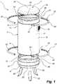
- Fig. 1shows a pressure tank for drinking water 1, whose main parts are a cylindrical mantle 2, a first round end section 4, and a second round end section 6.
- the mantle 2has a first cylinder end opening 8, which is located in a first end 10 of the mantle 2, and a second cylinder end opening 12, which is located in an opposite end 14 of the mantle 2.
- a valve connection socket 16, connected to the interior 17 of the mantle 2,is mounted in the side plate 18 of the mantle 2 close to the first end 10.
- the first cylinder end opening 8is surrounded by a first mantle flange 20 pointing outwards, located in the first end 10, and the other cylinder end opening 12 is surrounded by a second mantle flange 22 pointing outwards, located in the second end 14.
- the first end section 4comprises a curved first center section 24 and a first end flange 26 pointing outwards, located around the first center section 24.
- the second end part 6comprises a curved second center section 28 and a second end flange 30 pointing outwards, located around the second center section 28.
- the pressure tank 1furthermore is provided with a first fixation device, which in this embodiment is a first clamping ring 32, a first O-ring 34, and a first O-ring bracket 36.
- the clamping ring 32has a first ring half 38 and a second ring half 40 and each of these is provided with a respective bolt joint 42 for joining the two halves 38, 40.
- the pressure tank 1is also provided with a second fixation device, which in this embodiment is a second clamping ring 44, a second O-ring 46, and a second O-ring bracket 48, for the purpose of attaching the second end section 6 to the mantle 2.
- the clamping ring 44has a first ring half 50 and a second ring half 52 and each of these is provided with a respective bolt joint 54 for joining the two halves 50, 52.
- the first end section 4is arranged to be detachably mounted on either of the first or the second cylinder end openings 8, 12 using the first clamping ring 32
- the second end section 6is arranged to be detachably mounted on either of the first or the second cylinder end opening 8, 12 using the second clamping ring 44.
- the pressure tank 1may be provided with supporting legs, in Fig. 1 illustrated with three supporting legs 56. These legs 56 may be mounted on the tank 1, e.g., on the second end section 6, using bolts, a setup using grooves, or by any other suitable means (not shown in detail in Fig. 1 ).
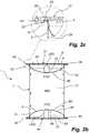
- Figs. 2a-2cshow the pressure tank for drinking water 1 in a transport configuration. In this configuration, the tank 1 takes up very little space, resulting in a low transport volume and low transport cost.
- Fig. 2ashows the tank 1 in transport configuration in a perspective view
- Fig. 2bshows the tank 1 in a cross-sectional view.
- Fig. 2cis an enlargement illustrating how the tank 1 is mounted in the transport configuration.
- Figs. 2a and 2bshow how the first end section 4 has been placed in the first cylinder end opening 8 of the mantle 2, it having been turned so that the outside 58 of its curved first center section 24 is pointed toward the interior 17 of the mantle 2.
- the second end section 6has been placed in the second cylinder end opening 12 of the mantle 2 and has been turned with the outside 60 of its curved second center section 28 pointed toward the interior 17 of the mantle 2.
- the first clamping ring 32has been mounted in the first end 10 of the mantle 2 using the bolt joints 42, which hold the first and the second ring halves 38, 40 together.
- the second clamping ring 44has been mounted in the second end 14 of the mantle 2 using the bolt joints 54, which hold the first and the second ring halves 50, 52 together.
- Fig. 2cshows how the first clamping ring 32 encloses the first mantle flange 20 pointing outwards of the mantle 2 and the first end flange 26 pointing outwards of the first end section 4, thereby attaching the first end section 4 on the mantle 2.
- no O-ring or other gasketis used to seal the first end section 4 against the mantle 2, and this is not needed in the transport configuration.
- the principle shown in Fig. 2cis also used in the way that the second clamping ring 44 fastens the second end section 6 on the mantle 2.
- the inside 62 of the first curved center section 24 of the first end section 4forms, in the transport configuration, a space 64 where equipment, schematically shown in Fig. 2b as a part UR1, may be stored during transport of the pressure tank 1.
- the inside 66 of the curved second center section 28 of the second end section 6forms a space 68 where equipment, schematically shown in Fig. 2b as a part UR2, may be stored during transport of the pressure tank 1.
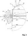
- Fig. 3shows how the first end section 4 has been mounted on the first cylinder end opening 8 at the first end 10 of the mantle 2 when then pressure tank for drinking water 1 has been mounted in a operative configuration.
- the fist O-ring bracket 36has an outside 70 that is essentially parallel to the inner wall 72 of the mantle 2, and a central opening 74 allowing water to freely flow past the central part of the O-ring bracket 36.
- the O-ring bracket 36has on its outside 70 a seal seating 71 intended for an O-ring.
- the first O-ring 34extends around the seal seating 71 located on the outside 70 of the O-ring bracket 36 and is at least partially located in a first gasket space 76 formed between the first mantle flange 20 pointing outward of the mantle 2 and the first end flange 26 pointing outward of the first end section 4.
- the clamping ring 32has been mounted using the bolt joint 42 so that the ring halves 38 and 40, of which only the ring half 40 is visible in the perspective view of Fig. 3 , have been pushed together.
- the ring half 40is V-shape on its inner side 78, which means that, as the clamping ring 32 is tightened, the inside 78 of the ring half 40 will push the mantle flange 20 and the end flange 26 against each other so that these two will clamp the O-ring 34 located in the gasket space 76 between themselves with increasing force the more the clamping ring 32 is tightened, thereby ensuring efficient sealing between the mantle 2 and the first end section 4. Thanks to the seating 71, the O-ring bracket 36 will be kept in place in the tank 1 by the O-ring 34, which in turn is locked in place in the gasket space 76.
- the clamping ring 32also functions as a relief valve.
- the clamping ring 32has been designed with a suitable strength so that the clamping ring 32 will yield and lose its sealing force if there is excess pressure inside the pressure tank 1. Thereby, possible excess pressure will in that case be released through the gasket space 76.
- the clamping ring 32may, e.g., be constructed to yield when the pressure inside the pressure tank for drinking water 1 exceeds a pre-determined security value, this pre-determined security value, e.g., being somewhere in the interval 5-25 bars (absolute pressure).
- the other clamping ring 44will, in a fashion similar to what is shown in Fig. 3 , ensure sealing between the mantle 2 and the second end section 6.
- Fig. 4ashows the pressure tank for drinking water 1 when it has been installed to be used as a pressure tank and as a filtering device.
- the mantle 2has been oriented so that the first end 10 of the mantle is facing upwards, and the second end 14 of the mantle is facing downwards, resulting in that the valve connection socket 16, which is located close to the first end 10, will be located in the upper end of the pressure tank 1.
- the first round end section 4has been mounted in the first end 10 of the mantle 2 with the aid of the first clamping ring 32 according to the principle described in Fig. 3
- the second round end section 6has been mounted on the second end 14 of the mantle 2 according to the same principle.
- three supporting legs 56have been mounted on the second round end section 6 so that the pressure tank 1 may be placed on the ground with the mantle 2 in a vertical direction.
- Fig. 4bshows the mode of operation of the pressure tank for drinking water 1 when it has been installed to be used as a pressure tank and as a filtering device to be part of a system for supplying drinking water 94.
- a schematically shown manual filter valve 80has been mounted on the valve connection socket 16.
- the manual filter valve 80may, e.g., be of the type "Manual Multi-Port Valve for Water Treatment Systems (TMF56A)", which is manufactured by Wenzhou Runxin Manufacturing Machine Co., Ltd., Wenzhou, China. This valve allows an inflow and an outflow to pass separately through the common valve connection socket 16.
- TMF56AManual Multi-Port Valve for Water Treatment Systems
- This valveallows an inflow and an outflow to pass separately through the common valve connection socket 16.
- a filtering material 82which, e.g., may contain sand, activated carbon, zeolites, or other filtering substances, and also mixtures of these materials, has been added inside the pressure tank 1 to a level just below the valve connection socket 16.
- the manual filter valve 80is connected to a feeder conduit 84 and a distributor pipe 86, and is also connected to a collecting pipe 88 and a drinking water conduit 90.
- the feeder conduit 84carries water, for example water from a drilled well (not shown), to the filter valve 80, which in turn carries the water on to the distributor pipe 86, which distributes the water over the filtering material 82. The water then continues vertically down through the filtering material 82 and is during this passage cleansed from impurities.
- the purified wateris collected in the collecting pipe 88 and is carried to the filter valve 80, which, without letting the pure water come into contact with the water in the feeder conduit 84, carries the water on to the drinking water conduit 90 and further on to different points of consumption, e.g., a kitchen, a shower, a wash basin, etc., on a premises.
- the feeder conduit 84may be connected to a pump 92, which generates a water pressure in the pressure tank 1 and which contributes to the functioning of the pressure tank both as a filter tank and as a hydrophore tank, which both purifies the water and generates the water pressure needed for the water to be easily drawn from taps, shower nozzles, etc.
- the pressure tank 1may be easily cleaned by removing one or both of the end sections 4, 6 from the mantle 2 when it is time to replace and/or clean the filtering material 82.
- valve connection socket 16When the pressure tank for drinking water 1 is to be used as a filter tank, it is normally advantageous to place the valve connection socket 16 at a high location, since it often is suitable to let an air bubble 93 exist in the upper part 1 of the tank, so that the water is saturated with oxygen before it is filtered.
- the tank 1will need to be back-flushed with some regularity, whereby water is pumped in a direction opposite to what is shown in Fig. 4b , to remove impurities which have been accumulating in the filtering material 82.
- the valve connection socket 16With the valve connection socket 16 at a high location, as is shown in Fig. 4b , the air bubble 93 located in the upper part of the tank 1, i.e., below the first end section 4, will remain during such back-flushing.
- the pressure tank for drinking wateris used both as a hydrophore tank and as a filter tank.
- Fig. 5ashows the pressure tank for drinking water 1 after it has been assembled to be used only as a hydrophore tank.
- the mantle 2has been positioned so that the first end 10 of the mantle 2 is facing downwards, and that the second en 14 of the mantle is facing upwards, resulting in that the valve connection socket 16, which is located close to the first end 10, will be located in the lower end of the pressure tank 1.
- the first round end section 4has been mounted on the second end 14 of the mantle 2 using the first clamping ring 32 according to the principle described in Fig. 3
- the second round end section 6has been mounted on the first en 10 of the mantle 2 using the second clamping ring 44 according to the same principle.
- three supporting legs 56have been mounted on the second round end section 6 so that the pressure tank 1 may be placed on the ground with the mantle 2 in a vertical direction.
- Fig. 5bshows the mode of operation for the pressure tank for drinking water 1 when it has been mounted to only be used as a hydrophore tank, forming part of a system for supplying drinking water 194.
- a schematically shown manual distributor valve 180has been mounted on the valve connection socket 16.
- the manual distributor valve 180may be of the same type as the valve 80 mentioned above.
- the manual distributor valve 180is connected to a feeder conduit 184 and to a distributor pipe 186, and is also connected to an outlet pipe 188 and a drinking water conduit 190.
- a pump 192pressurizes and transports drinking water, via the feeder conduit 184, to the distributor valve 180, which carries the water to the distributor pipe 186.
- the distributor pipe 186releases the water into the upper part of the pressure tank 1, close to the first round end section 4.
- the outlet pipe 188has its mouth located in the opposite end of the tank 1, viz., in the vicinity of the other round end section 6, as compared to the end where the distributor pipe 186 has its mouth, and therefore the water in the tank 1 will be mixed every time someone draws water.
- the wateris thus carried from the outlet pipe 188, through the valve 180 and the drinking water conduit 190, and further on to the different points of consumption, e.g., a kitchen, a shower, a wash basin, etc., on a premises.
- the pressure tank for drinking wateronly will be used a hydrophore tank, it is normally advantageous to place the valve connection socket 16 at as low a level as possible, since this results in comparatively short water conduits.
- the pressure tank 1may easily be disassembled during possible cleaning or inspection.
- both the inflow and the outflow of the tank 1have been described as going through a single valve connection socket 16.
- a tank outlet and a tank inletare separate from each other. These inlets or outlets may be located in the mantle 2, and/or in any of the end sections 4, 6, or in both.
- the end sections 4, 6have been described as being virtually identical in design. It is also possible to design the two end sections 4, 6 so that they are different.
- the first end section 4may, e.g., be provided with connectors for supplying air and/or an inlet for a liquid, and the second end section 6 may be provided with fastening means for the supporting legs 56, or be provided with permanently mounted supporting legs.
Landscapes
- Engineering & Computer Science (AREA)
- Hydrology & Water Resources (AREA)
- Structural Engineering (AREA)
- Health & Medical Sciences (AREA)
- Life Sciences & Earth Sciences (AREA)
- General Engineering & Computer Science (AREA)
- Public Health (AREA)
- Water Supply & Treatment (AREA)
- Chemical & Material Sciences (AREA)
- Chemical Kinetics & Catalysis (AREA)
- Mechanical Engineering (AREA)
- Devices For Dispensing Beverages (AREA)
- Thermally Insulated Containers For Foods (AREA)
- Devices That Are Associated With Refrigeration Equipment (AREA)
Description
- The present invention relates to a pressure tank for drinking water configured for operation as a hydrophore tank, according to the preamble of
claim 1, said tank having a cylindrical mantle, a first end section and a second end section. Further, it relates to a kit for assembling such a pressure tank according to the preamble ofclaim 12. - Systems for supplying drinking water to, e.g., homes, especially those supplying homes outside of built-up areas, often include a pressure tank. This tank may operate as a hydrophore tank, i.e., function as container of pressurized water, which acts as a reservoir of pressurized water and is connected to the water conduit system of the home in question. A pump is connected to the hydrophore tank and pumps water to the hydrophore tank from, e.g., a drilled well. Using the hydrophore tank, a pressure is achieved in the water conduits which will vary between pre-set pressures for the pump to turn on or off. Thanks to the hydrophore tank, the pump will not need to start every time a water tap is opened in the water conduit system.
- A hydrophore is disclosed in
SE392794B - A system for supplying drinking water may also comprise a filter tank which is filled with a suitable filtering material, e.g., sand or activated carbon, and which filters water from, e.g., a well before the water is forwarded to a water conduit system.
DE 20 2004 008 670 U1 describes a water softening installation. The installation comprises a pressure tank. <Insert Page 1a>- It is an object of the present invention to produce a pressure tank for drinking water which is more efficient in transport and manufacture than pressure tanks for drinking water known in the prior art.
- This object is achieved through a pressure tank according to
claim 1. - An example of a plastic container for storage and transport of large volumes of a liquid media, such as rainwater, is disclosed in
DE 198 18 709 A1 . - An example of a container with segmental construction for storage of large volumes of a liquid is disclosed in
EP 2 244 047 A1 - An example of a water tank made of a plastic material, which water tank is formed by joining at least two open tank parts with opened end structures, is disclosed in
EP 1 894 855 A1 - An example of a recyclable container made of metal for storage of a liquid or semiliquid material, which can be extracted from the container by use of a plunger, is disclosed in
US 5 465 863 A . - An example of a metal container for transport of a liquid material, where the container has been reinforced to prevent bulging is disclosed in
GB 490 201 A - An advantage of this pressure tank for drinking water is that it allows for considerable freedom of assembling; it may for example be assembled with the cylindrical mantle oriented differently depending on whether the pressure tank for drinking water will be used as a pressure tank for drinking water and/or filter tank for drinking water. Another advantage is that the interior of the pressure tank for drinking water is very easily accessible for cleaning. Should any part of the pressure tank for drinking water be damaged, only that part will need to be replaced, while the undamaged part of the filer tank may be kept.
- In an embodiment, the cylindrical mantle has at its first end a first mantle flange pointing outwards, and at its second end a second mantle flange pointing outwards, and wherein the first end section has a first end flange pointing outwards, which flange is adapted to the first and second mantle flanges, and the second end section has a second end flange pointing outwards, which flange is adapted to the first and the second mantle flanges. An advantage with this embodiment is that the flanges make it easy to mount any end section on any end of the cylindrical mantle.
- At least the first end section has a curved first center section, whose outer diameter FYD is equal to or less than the inner diameter MID of the mantle, wherein the first end section may be positioned with the whole of the first center section inside the mantle in a transport configuration. Therefore, the tank for drinking water has a very small transport volume, making transport inexpensive and efficient.
- According to an embodiment, the other end section has a curved second center section, whose outer diameter AYD is equal to or less than the inner diameter MID of the mantle, wherein both the first and the second end sections may be placed with the whole of their respective curved center sections inside the mantle in a transport configuration. This allows for an exceptionally small transport volume, resulting in efficient and inexpensive transport.
- According to an embodiment, the pressure tank for drinking water has a first fixation device which is arranged to fasten the first end section on either one of the first or the second cylinder end openings, and a second fixation device which is designed to fasten the second end section on either one of the first or the second cylinder end openings. An advantage of this embodiment is that the end sections may be attached to any cylinder end opening in an easy way.
- According to an embodiment, at least one of the first and the second fixation devices has a V-shaped inner side and is designed to push with this inner side on, respectively, a first mantle flange pointing outwards being located on the mantle and a first or second end flange located on the first or second end flange against each other to clamp a sealing device located between the first mantle flange and the first or the second end flange, for example an O-ring. An advantage of this embodiment is that the end sections may be efficiently attached on the mantle with the help of the fixation devices, and that these at the same time ensure efficient sealing of the end sections against the mantle.
- According to an embodiment, at least one of the first or the second fixation devices is a clamping ring with at least two parts. An advantage of this embodiment is that the fixation devices are inexpensive to make and easy to assemble and disassemble.
- According to an embodiment, at least one of the first and the second fixation devices are designed to fasten an end section on the mantle both in a transport configuration and in an operative configuration. An advantage of this embodiment is that few parts are needed, since the fixation device also functions as a transport locking device.
- According to an embodiment, at least one of the first and the second fixation devices has been constructed to yield to overpressure in the pressure tank for drinking water. An advantage of this embodiment is that there is no need for a separate relief valve, since this feature is achieved through at least one of the fixation devices. Thus, the fixation device will additionally serve as relief valve. An efficient design with few parts is thus achieved, lowering cost. The fixation device may, e.g., be designed to yield when the pressure inside the pressure tank for drinking water exceeds a pre-determined security value, and this pre-determined security value may, e.g., be somewhere in the interval 5-25 bars (absolute pressure).
- According to an embodiment, the pressure tank for drinking water further comprises a first sealing ring for sealing a gasket space between the first cylinder end opening and optionally the first or the second end section, and a second sealing ring for sealing a gasket space between the second cylinder end opening and optionally the first or the second end section. An advantage of this embodiment is that sealing rings allow for efficient sealing between either of the respective end sections and the mantle. According to a preferred embodiment, either of the sealing rings may be an O-ring. An advantage of this embodiment is that O-rings allow for efficient and safe sealing at low cost.
- According to an embodiment, the pressure tank for drinking water comprises at least a first circular seal bracket which is located inside the pressure tank for drinking water, and which on its outside supports a first sealing, e.g., a first O-ring, positioning this first sealing in a gasket space formed between the first cylinder end opening and optionally the first or the second end section. An advantage of this embodiment is the ease of assuring that the first sealing, e.g., a first O-ring, is correctly positioned in the gasket space when assembling the pressure tank for drinking water. According to a preferred embodiment the pressure tank for drinking water comprises a first seal bracket located at the first cylinder end opening and a second sealing bracket located at the second cylinder end opening. An advantage of this embodiment is that it allows for very easy assembling of the pressure tank for drinking water. According to an embodiment, the seal bracket has a seal seating for the first sealing. The seating keeps the sealing in place during assembling of the pressure tank, and keeps the seal bracket in place in the tank after the assembling of the tank.
- According to an embodiment, a valve connection socket, connected to the interior of the mantle, is attached on the mantle close to the first end. An advantage of this embodiment is that the pressure tank for drinking water easily may be connected to a water conduit system. The mantle may be positioned with either end pointing upwards, i.e., with the valve connection socket close to the floor or far from the floor, for the best adaptation to the intended function, e.g., as a filter tank or only as a pressure tank.
- According to an aspect, the present invention relates to a system for supplying drinking water, comprising a pressure tank for drinking water according to any one of the embodiments described above, which is configured to operate as a hydrophore tank in the system for supplying drinking water. An advantage of this is the provision of an inexpensive and easily cleaned system for supplying drinking water.
- According to an aspect, the present invention relates to a system for supplying drinking water, comprising a pressure tank for drinking water according to any one of the embodiments described above, which is configured to operate as a filter tank for drinking water in the system for supplying drinking water. An advantage of this is the provision of a system for supplying drinking water that has a water filter that is inexpensive and in which the filtering material is easy to replace.
- According to another aspect, the present invention relates to a system for supplying drinking water, comprising a pressure tank for drinking water according to any one of the embodiments described above, which is configured to operate as both a hydrophore tank and as a filter tank for drinking water in the system for supplying drinking water. An advantage of this is the provision of a system for supplying drinking water that is easy to maintain and has few parts.
- Further advantages and characteristics of the invention will be evident from the description below and the claims following thereafter.
- The invention will in the following be described with the help of example embodiments with reference to the attached drawings.
Fig. 1 is an exploded view showing parts comprising a pressure tank for drinking water.Fig. 2a is a three-dimensional view showing the pressure tank ofFig. 1 in a transport configuration.Fig. 2b is a cross-sectional view of the pressure tank in transport configuration.Fig. 2c is an enlargement of a clamping ring holding the pressure tank together in transport configuration.Fig. 3 is a cross-sectional view showing a sealing device which is part of the pressure tank for drinking water.Fig. 4a is a three-dimensional view showing the pressure tank for drinking water configured to operate as a pressure tank and as a filtering device.Fig. 4b shows the flow of water in the pressure tank when it is configured to operate as a filtering device.Fig. 5a is a three-dimensional view showing the pressure tank for drinking water configured to operate as a hydrophore tank.Fig. 5b shows the flow of water in the pressure tank configured to operate as a hydrophore tank.Fig. 1 shows a pressure tank for drinkingwater 1, whose main parts are acylindrical mantle 2, a firstround end section 4, and a secondround end section 6.- The
mantle 2 has a firstcylinder end opening 8, which is located in afirst end 10 of themantle 2, and a secondcylinder end opening 12, which is located in anopposite end 14 of themantle 2. Avalve connection socket 16, connected to the interior 17 of themantle 2, is mounted in theside plate 18 of themantle 2 close to thefirst end 10. - The first
cylinder end opening 8 is surrounded by afirst mantle flange 20 pointing outwards, located in thefirst end 10, and the othercylinder end opening 12 is surrounded by asecond mantle flange 22 pointing outwards, located in thesecond end 14. - The
first end section 4 comprises a curvedfirst center section 24 and afirst end flange 26 pointing outwards, located around thefirst center section 24. In a similar way, thesecond end part 6 comprises a curvedsecond center section 28 and asecond end flange 30 pointing outwards, located around thesecond center section 28. - For the purpose of attaching the
first end section 4 to themantle 2, thepressure tank 1 furthermore is provided with a first fixation device, which in this embodiment is afirst clamping ring 32, a first O-ring 34, and a first O-ring bracket 36. The clampingring 32 has afirst ring half 38 and asecond ring half 40 and each of these is provided with a respective bolt joint 42 for joining the twohalves - In the same way, the
pressure tank 1 is also provided with a second fixation device, which in this embodiment is asecond clamping ring 44, a second O-ring 46, and a second O-ring bracket 48, for the purpose of attaching thesecond end section 6 to themantle 2. The clampingring 44 has afirst ring half 50 and asecond ring half 52 and each of these is provided with a respective bolt joint 54 for joining the twohalves - The
first end section 4 is arranged to be detachably mounted on either of the first or the secondcylinder end openings first clamping ring 32, and thesecond end section 6 is arranged to be detachably mounted on either of the first or the secondcylinder end opening second clamping ring 44. - Furthermore, the
pressure tank 1 may be provided with supporting legs, inFig. 1 illustrated with three supportinglegs 56. Theselegs 56 may be mounted on thetank 1, e.g., on thesecond end section 6, using bolts, a setup using grooves, or by any other suitable means (not shown in detail inFig. 1 ). Figs. 2a-2c show the pressure tank for drinkingwater 1 in a transport configuration. In this configuration, thetank 1 takes up very little space, resulting in a low transport volume and low transport cost.Fig. 2a shows thetank 1 in transport configuration in a perspective view, andFig. 2b shows thetank 1 in a cross-sectional view.Fig. 2c is an enlargement illustrating how thetank 1 is mounted in the transport configuration.Figs. 2a and2b show how thefirst end section 4 has been placed in the first cylinder end opening 8 of themantle 2, it having been turned so that the outside 58 of its curvedfirst center section 24 is pointed toward the interior 17 of themantle 2. As is best seen inFig. 2b , thesecond end section 6 has been placed in the second cylinder end opening 12 of themantle 2 and has been turned with the outside 60 of its curvedsecond center section 28 pointed toward the interior 17 of themantle 2.- This transport configuration is possible thanks to the outer diameter FYD of the
first center section 24 being equal to, or somewhat less than, the inner diameter MID of themantle 2, as well as the outer diameter AYD of thesecond center section 28 being equal to, or somewhat less than, the inner diameter MID of themantle 2, i.e., FYD, AYD =< MID. Because of this, each of therespective center sections end sections mantle 2. - The
first clamping ring 32 has been mounted in thefirst end 10 of themantle 2 using the bolt joints 42, which hold the first and the second ring halves 38, 40 together. Similarly, thesecond clamping ring 44 has been mounted in thesecond end 14 of themantle 2 using the bolt joints 54, which hold the first and the second ring halves 50, 52 together. Fig. 2c shows how thefirst clamping ring 32 encloses thefirst mantle flange 20 pointing outwards of themantle 2 and thefirst end flange 26 pointing outwards of thefirst end section 4, thereby attaching thefirst end section 4 on themantle 2. In this configuration, no O-ring or other gasket is used to seal thefirst end section 4 against themantle 2, and this is not needed in the transport configuration. The principle shown inFig. 2c is also used in the way that thesecond clamping ring 44 fastens thesecond end section 6 on themantle 2.- As is schematically shown in
Figs. 2a and2b , the inside 62 of the firstcurved center section 24 of thefirst end section 4 forms, in the transport configuration, aspace 64 where equipment, schematically shown inFig. 2b as a part UR1, may be stored during transport of thepressure tank 1. In the same way, the inside 66 of the curvedsecond center section 28 of thesecond end section 6 forms aspace 68 where equipment, schematically shown inFig. 2b as a part UR2, may be stored during transport of thepressure tank 1. Fig. 3 shows how thefirst end section 4 has been mounted on the firstcylinder end opening 8 at thefirst end 10 of themantle 2 when then pressure tank for drinkingwater 1 has been mounted in a operative configuration. As can be seen inFig. 3 , and as has already been discussed in conjunction withFig. 2b , the outer diameter FYD of thecenter section 24 is equal to, or somewhat less than, the inner diameter MID of themantle 2, i.e., FYD =< MID.- The first O-
ring bracket 36 has an outer diameter RHY which is equal to, or somewhat less than, the inner diameter MID of themantle 2, i.e., RHY =< MID. The fist O-ring bracket 36 has an outside 70 that is essentially parallel to theinner wall 72 of themantle 2, and acentral opening 74 allowing water to freely flow past the central part of the O-ring bracket 36. The O-ring bracket 36 has on its outside 70 aseal seating 71 intended for an O-ring. The first O-ring 34 extends around theseal seating 71 located on the outside 70 of the O-ring bracket 36 and is at least partially located in afirst gasket space 76 formed between thefirst mantle flange 20 pointing outward of themantle 2 and thefirst end flange 26 pointing outward of thefirst end section 4. The clampingring 32 has been mounted using the bolt joint 42 so that the ring halves 38 and 40, of which only thering half 40 is visible in the perspective view ofFig. 3 , have been pushed together. - As can be seen in
Fig. 3 , thering half 40 is V-shape on itsinner side 78, which means that, as the clampingring 32 is tightened, the inside 78 of thering half 40 will push themantle flange 20 and theend flange 26 against each other so that these two will clamp the O-ring 34 located in thegasket space 76 between themselves with increasing force the more the clampingring 32 is tightened, thereby ensuring efficient sealing between themantle 2 and thefirst end section 4. Thanks to theseating 71, the O-ring bracket 36 will be kept in place in thetank 1 by the O-ring 34, which in turn is locked in place in thegasket space 76. - The clamping
ring 32 also functions as a relief valve. The clampingring 32 has been designed with a suitable strength so that the clampingring 32 will yield and lose its sealing force if there is excess pressure inside thepressure tank 1. Thereby, possible excess pressure will in that case be released through thegasket space 76. The clampingring 32 may, e.g., be constructed to yield when the pressure inside the pressure tank for drinkingwater 1 exceeds a pre-determined security value, this pre-determined security value, e.g., being somewhere in the interval 5-25 bars (absolute pressure). - The
other clamping ring 44 will, in a fashion similar to what is shown inFig. 3 , ensure sealing between themantle 2 and thesecond end section 6. Fig. 4a shows the pressure tank for drinkingwater 1 when it has been installed to be used as a pressure tank and as a filtering device. In this mode of operation, themantle 2 has been oriented so that thefirst end 10 of the mantle is facing upwards, and thesecond end 14 of the mantle is facing downwards, resulting in that thevalve connection socket 16, which is located close to thefirst end 10, will be located in the upper end of thepressure tank 1. The firstround end section 4 has been mounted in thefirst end 10 of themantle 2 with the aid of thefirst clamping ring 32 according to the principle described inFig. 3 , and the secondround end section 6 has been mounted on thesecond end 14 of themantle 2 according to the same principle. Thereafter, three supportinglegs 56 have been mounted on the secondround end section 6 so that thepressure tank 1 may be placed on the ground with themantle 2 in a vertical direction.Fig. 4b shows the mode of operation of the pressure tank for drinkingwater 1 when it has been installed to be used as a pressure tank and as a filtering device to be part of a system for supplyingdrinking water 94. A schematically shownmanual filter valve 80 has been mounted on thevalve connection socket 16. Themanual filter valve 80 may, e.g., be of the type "Manual Multi-Port Valve for Water Treatment Systems (TMF56A)", which is manufactured by Wenzhou Runxin Manufacturing Machine Co., Ltd., Wenzhou, China. This valve allows an inflow and an outflow to pass separately through the commonvalve connection socket 16. Naturally, it is also possible to mount other types of valves, including automatic and/or electronically controlled valves.- A
filtering material 82, which, e.g., may contain sand, activated carbon, zeolites, or other filtering substances, and also mixtures of these materials, has been added inside thepressure tank 1 to a level just below thevalve connection socket 16. Themanual filter valve 80 is connected to afeeder conduit 84 and adistributor pipe 86, and is also connected to a collectingpipe 88 and adrinking water conduit 90. Thefeeder conduit 84 carries water, for example water from a drilled well (not shown), to thefilter valve 80, which in turn carries the water on to thedistributor pipe 86, which distributes the water over the filteringmaterial 82. The water then continues vertically down through thefiltering material 82 and is during this passage cleansed from impurities. The purified water is collected in the collectingpipe 88 and is carried to thefilter valve 80, which, without letting the pure water come into contact with the water in thefeeder conduit 84, carries the water on to thedrinking water conduit 90 and further on to different points of consumption, e.g., a kitchen, a shower, a wash basin, etc., on a premises. Thefeeder conduit 84 may be connected to apump 92, which generates a water pressure in thepressure tank 1 and which contributes to the functioning of the pressure tank both as a filter tank and as a hydrophore tank, which both purifies the water and generates the water pressure needed for the water to be easily drawn from taps, shower nozzles, etc. - Thanks to the clamping rings 32, 44, the
pressure tank 1 may be easily cleaned by removing one or both of theend sections mantle 2 when it is time to replace and/or clean thefiltering material 82. - When the pressure tank for drinking
water 1 is to be used as a filter tank, it is normally advantageous to place thevalve connection socket 16 at a high location, since it often is suitable to let anair bubble 93 exist in theupper part 1 of the tank, so that the water is saturated with oxygen before it is filtered. Thetank 1 will need to be back-flushed with some regularity, whereby water is pumped in a direction opposite to what is shown inFig. 4b , to remove impurities which have been accumulating in thefiltering material 82. With thevalve connection socket 16 at a high location, as is shown inFig. 4b , theair bubble 93 located in the upper part of thetank 1, i.e., below thefirst end section 4, will remain during such back-flushing. - In the configuration shown in
Figs. 4a-4b , the pressure tank for drinking water is used both as a hydrophore tank and as a filter tank. Fig. 5a shows the pressure tank for drinkingwater 1 after it has been assembled to be used only as a hydrophore tank. In this mode of operation, themantle 2 has been positioned so that thefirst end 10 of themantle 2 is facing downwards, and that the second en 14 of the mantle is facing upwards, resulting in that thevalve connection socket 16, which is located close to thefirst end 10, will be located in the lower end of thepressure tank 1. The firstround end section 4 has been mounted on thesecond end 14 of themantle 2 using thefirst clamping ring 32 according to the principle described inFig. 3 , and the secondround end section 6 has been mounted on the first en 10 of themantle 2 using thesecond clamping ring 44 according to the same principle. Thereafter, three supportinglegs 56 have been mounted on the secondround end section 6 so that thepressure tank 1 may be placed on the ground with themantle 2 in a vertical direction.Fig. 5b shows the mode of operation for the pressure tank for drinkingwater 1 when it has been mounted to only be used as a hydrophore tank, forming part of a system for supplyingdrinking water 194. A schematically shownmanual distributor valve 180 has been mounted on thevalve connection socket 16. Themanual distributor valve 180 may be of the same type as thevalve 80 mentioned above. Themanual distributor valve 180 is connected to afeeder conduit 184 and to adistributor pipe 186, and is also connected to anoutlet pipe 188 and adrinking water conduit 190. Apump 192 pressurizes and transports drinking water, via thefeeder conduit 184, to thedistributor valve 180, which carries the water to thedistributor pipe 186. Thedistributor pipe 186 releases the water into the upper part of thepressure tank 1, close to the firstround end section 4. When water is to be drawn from thepressure tank 1, it is carried out from thepressure tank 1 through theoutlet pipe 188. Theoutlet pipe 188 has its mouth located in the opposite end of thetank 1, viz., in the vicinity of the otherround end section 6, as compared to the end where thedistributor pipe 186 has its mouth, and therefore the water in thetank 1 will be mixed every time someone draws water. The water is thus carried from theoutlet pipe 188, through thevalve 180 and thedrinking water conduit 190, and further on to the different points of consumption, e.g., a kitchen, a shower, a wash basin, etc., on a premises. When the pressure tank for drinking water only will be used a hydrophore tank, it is normally advantageous to place thevalve connection socket 16 at as low a level as possible, since this results in comparatively short water conduits.- Thanks to the clamping rings 32, 44, the
pressure tank 1 may easily be disassembled during possible cleaning or inspection. - It is easily understood that the present invention may be realized in alternative ways, within the scope of the following claims.
- Above, both the inflow and the outflow of the
tank 1 have been described as going through a singlevalve connection socket 16. Is can be understood that it is also possible to design a tank outlet and a tank inlet with are separate from each other. These inlets or outlets may be located in themantle 2, and/or in any of theend sections - Above, the
end sections end sections first end section 4 may, e.g., be provided with connectors for supplying air and/or an inlet for a liquid, and thesecond end section 6 may be provided with fastening means for the supportinglegs 56, or be provided with permanently mounted supporting legs.
Claims (12)
- A pressure tank for drinking water (1) configured for operation as a hydrophore tank, said tank having a cylindrical mantle (2), a first end section (4), and a second end section (6), said cylindrical mantle (2) having a first cylinder end opening (8) located in a first end (10) of said mantle (2), and a second cylinder end opening (12) located in an opposite end (14) of said mantle (2), wherein said first end section (4) is detachably mounted on any one of said first or said second cylinder end openings (8, 12), and wherein said second end section (6) is detachably mounted on any one of said second or said first cylinder end openings (12, 8),characterized in that at least said first end section (4) has a curved first center section (24), whose outer diameter (FYD) is equal to or less than the inner diameter (MID) of said mantle (2), wherein said first end section (4) may be positioned with the whole of said curved first center section (24) inside said mantle (2) in a transport configuration.
- A pressure tank for drinking water (1) according to claim 1, wherein said cylindrical mantle (2) at its said first end (10) has a first mantle flange (20) pointing outwards, and at its said second end (14) a second mantle flange (22) pointing outwards, and wherein said first end section (4) has a first end flange (26) pointing outwards, said flange being adapted to said first and said second mantle flanges (20, 22), and said second end section (6) has a second end flange (30) pointing outwards, said flange being adapted to said first and said second mantle flanges (20, 22).
- A pressure tank for drinking water (1) according to any one of the preceding claims, wherein said second end section (6) has a curved second center section (28), whose outer diameter (AYD) is equal to or less than said inner diameter (MID) of said mantle (2), wherein both said second and said first end section (4, 6) may be placed with the whole of their said respective curved center sections (24, 28) inside said mantle (2) in a transport configuration.
- A pressure tank for drinking water (1) according to any one of the preceding claims, having a first fixation device (32) which is arranged to fasten said first end section (4) on any one of said first or said second cylinder end openings (8, 12), and a second fixation device (44) which is arranged to fasten said second end section (6) on any one of said first and said second cylinder end openings (8, 12).
- A pressure tank for drinking water (1) according to claim 4, wherein at least one of said first and said second fixation devices (32, 44) has a V-shaped inner side (78) and is arranged to push, using said inner side (78), on, respectively, a first mantle flange (20) pointing outwards located on said mantle (2) and on a first or a second end flange (26, 30) located on said first or said second end sections (4, 6) against each other to clamp a sealing device (34), for example an O-ring, located between said first mantle flange (20) and said first or said second end flanges (26, 30).
- A pressure tank for drinking water (1) according to any one of claims 4-5, wherein at least one of said first and said second fixation devices comprises a clamping ring (32, 44) constructed with a suitable strength so as to yield and lose its sealing force if the pressure inside the pressure tank exceeds a pre-determined security value.
- A pressure tank for drinking water (1) according to any one of the preceding claims, wherein said pressure tank for drinking water (1) further comprises a first sealing ring (34) for sealing a gasket space (76) between said first cylinder end opening (8) and optionally said first or said second end section (4, 6), and a second sealing ring (46) for sealing a gasket space (76) between said second cylinder end opening (12) and optionally said first or said second end section (4, 6).
- A pressure tank for drinking water (1) according to any one of the preceding claims, comprising at least a first circular seal bracket (36), which is located inside said pressure tank for drinking water (1), and which in its outside (70) supports a first sealing (34), such as a first O-ring, and positions said first sealing (34) in a gasket space formed between said first cylinder end opening (8) and optionally said first or said second end opening (4, 6).
- A pressure tank for drinking water (1) according to any one of the preceding claims, wherein a valve connection socket (16), being connected to the interior (17) of said mantle (2), is mounted on said mantle (2) close said the first end (10).
- A system (94, 194) for supplying drinking water,characterized by comprising a pressure tank for drinking water (1) according to any one of the preceding claims, which is configured to operate as a hydrophore tank in said system for supplying drinking water (94, 194).
- A system (94) for supplying drinking water,characterized by comprising a pressure tank for drinking water (1) according to any one of the preceding claims 1-9, which is configured to operate as a filter tank in said system for supplying drinking water (94).
- A kit for assembling a pressure tank for drinking water (1), said pressure tank being configurable for operation as a hydrophore tank, said kit comprising a cylindrical mantle (2), a first end section (4), and a second end section (6), said cylindrical mantle (2) having a first cylinder end opening (8) located in a first end (10) of said mantle (2), and a second cylinder end opening (12) located in an opposite end (14) of said mantle (2), wherein said first end section (4) is arranged to be detachably mounted on any one of said first or said second cylinder end openings (8, 12), and wherein said second end section (6) is arranged to be detachably mounted on any one of said second or said first cylinder end openings (12, 8),characterized in that at least said first end section (4) has a curved first center section (24), whose outer diameter (FYD) is equal to or less than the inner diameter (MID) of said mantle (2), wherein said first end section (4) may be positioned with the whole of said curved first center section (24) inside said mantle (2) in a transport configuration.
Applications Claiming Priority (1)
| Application Number | Priority Date | Filing Date | Title |
|---|---|---|---|
| SE1450355ASE537913C2 (en) | 2014-03-27 | 2014-03-27 | Drinking Water Pressure Tank |
Publications (2)
| Publication Number | Publication Date |
|---|---|
| EP2930276A1 EP2930276A1 (en) | 2015-10-14 |
| EP2930276B1true EP2930276B1 (en) | 2022-12-28 |
Family
ID=52987878
Family Applications (1)
| Application Number | Title | Priority Date | Filing Date |
|---|---|---|---|
| EP15160340.4AActiveEP2930276B1 (en) | 2014-03-27 | 2015-03-23 | Pressure tank for drinking water |
Country Status (7)
| Country | Link |
|---|---|
| EP (1) | EP2930276B1 (en) |
| DK (1) | DK2930276T3 (en) |
| ES (1) | ES2940566T3 (en) |
| FI (1) | FI2930276T3 (en) |
| PL (1) | PL2930276T3 (en) |
| PT (1) | PT2930276T (en) |
| SE (1) | SE537913C2 (en) |
Cited By (1)
| Publication number | Priority date | Publication date | Assignee | Title |
|---|---|---|---|---|
| US12330098B2 (en) | 2018-11-29 | 2025-06-17 | Fluitec N.V. | Filter housings, purification skids and methods of use thereof |
Families Citing this family (3)
| Publication number | Priority date | Publication date | Assignee | Title |
|---|---|---|---|---|
| EP3964482B1 (en)* | 2020-09-08 | 2024-04-17 | Aqua Expert AB | Combined pressurized water tank and water filter |
| KR20230053367A (en)* | 2021-10-14 | 2023-04-21 | 코웨이 주식회사 | Water purifier |
| CN118491999A (en)* | 2024-05-15 | 2024-08-16 | 华能国际电力股份有限公司丹东电厂 | Ultra-high temperature purification device for heating water-drain impurity treatment |
Citations (6)
| Publication number | Priority date | Publication date | Assignee | Title |
|---|---|---|---|---|
| US2209663A (en)* | 1938-06-17 | 1940-07-30 | Frederick P Riedel | Container |
| US2696323A (en)* | 1951-01-25 | 1954-12-07 | Kenyon B Sanderson | Barrel |
| US2971671A (en)* | 1956-10-31 | 1961-02-14 | Pabst Brewing Co | Container |
| SE392794B (en)* | 1976-09-30 | 1977-04-25 | Fogelstad Seteri Ab | IRRIGATION DEVICE |
| DE202004008670U1 (en)* | 2004-05-29 | 2005-10-13 | Hannemann, Mike | Drinking water softener assembly for use in association with e.g. central heating system has pressure tank resting in wheeled frame |
| CN202000404U (en)* | 2011-02-25 | 2011-10-05 | 河南惠洁管业有限公司 | Socket reinforcing type household tower-free water feeder |
Family Cites Families (5)
| Publication number | Priority date | Publication date | Assignee | Title |
|---|---|---|---|---|
| GB490201A (en)* | 1938-04-20 | 1938-08-10 | Ig Farbenindustrie Ag | Improvements in and relating to containers for transport purposes |
| US5465863A (en)* | 1993-03-10 | 1995-11-14 | Greif Bros. Corporation | Recyclable steel drum for hot flow products |
| DE19818709B4 (en)* | 1998-04-21 | 2007-10-11 | Richter, Günter, Dipl.-Ing. | Storage and transport device for liquid media |
| ATE418508T1 (en)* | 2006-09-04 | 2009-01-15 | Graf Plastics Gmbh | WATER TANK AND METHOD OF MAKING WATER TANK |
| EP2244047A1 (en)* | 2009-03-30 | 2010-10-27 | Hermann Isenmann | Storage container and ring disc for sealing a flange connector |
- 2014
- 2014-03-27SESE1450355Apatent/SE537913C2/enunknown
- 2015
- 2015-03-23PTPT151603404Tpatent/PT2930276T/enunknown
- 2015-03-23DKDK15160340.4Tpatent/DK2930276T3/enactive
- 2015-03-23EPEP15160340.4Apatent/EP2930276B1/enactiveActive
- 2015-03-23PLPL15160340.4Tpatent/PL2930276T3/enunknown
- 2015-03-23ESES15160340Tpatent/ES2940566T3/enactiveActive
- 2015-03-23FIFIEP15160340.4Tpatent/FI2930276T3/enactive
Patent Citations (6)
| Publication number | Priority date | Publication date | Assignee | Title |
|---|---|---|---|---|
| US2209663A (en)* | 1938-06-17 | 1940-07-30 | Frederick P Riedel | Container |
| US2696323A (en)* | 1951-01-25 | 1954-12-07 | Kenyon B Sanderson | Barrel |
| US2971671A (en)* | 1956-10-31 | 1961-02-14 | Pabst Brewing Co | Container |
| SE392794B (en)* | 1976-09-30 | 1977-04-25 | Fogelstad Seteri Ab | IRRIGATION DEVICE |
| DE202004008670U1 (en)* | 2004-05-29 | 2005-10-13 | Hannemann, Mike | Drinking water softener assembly for use in association with e.g. central heating system has pressure tank resting in wheeled frame |
| CN202000404U (en)* | 2011-02-25 | 2011-10-05 | 河南惠洁管业有限公司 | Socket reinforcing type household tower-free water feeder |
Cited By (1)
| Publication number | Priority date | Publication date | Assignee | Title |
|---|---|---|---|---|
| US12330098B2 (en) | 2018-11-29 | 2025-06-17 | Fluitec N.V. | Filter housings, purification skids and methods of use thereof |
Also Published As
| Publication number | Publication date |
|---|---|
| PT2930276T (en) | 2023-03-22 |
| PL2930276T3 (en) | 2023-05-02 |
| ES2940566T3 (en) | 2023-05-09 |
| FI2930276T3 (en) | 2023-04-03 |
| SE1450355A1 (en) | 2015-09-28 |
| SE537913C2 (en) | 2015-11-17 |
| DK2930276T3 (en) | 2023-04-03 |
| EP2930276A1 (en) | 2015-10-14 |
Similar Documents
| Publication | Publication Date | Title |
|---|---|---|
| EP2930276B1 (en) | Pressure tank for drinking water | |
| EP1485181B1 (en) | Self-cleaning fluid filter system | |
| KR101188143B1 (en) | Trainer establishment structure for waterworks piping | |
| KR20170033260A (en) | Fluid filter insert and fluid spreader | |
| US20140215709A1 (en) | Sink Faucet Assembly | |
| US9630856B2 (en) | Water filter faucet and cartridge therefor | |
| CN108585252B (en) | Environment-friendly household water purifier | |
| KR102342293B1 (en) | Connecting structure of filter cartridge for water purifier | |
| US20140158590A1 (en) | Apparatus for a parallel flow manifold system for water filtration | |
| US20110297624A1 (en) | Showerhead filter assembly and method of purification | |
| KR101430429B1 (en) | Install mount for direct receiving type water purifier | |
| CN104955773A (en) | Water purifier | |
| KR102215229B1 (en) | Water pipe for water meter box having filter | |
| KR200403991Y1 (en) | Apparatus for filtering for water purification system | |
| KR101776256B1 (en) | The Piping Onebody Cover for Water purifier | |
| CN107337290A (en) | Pump-free water purification system and water purifier | |
| FI97448C (en) | filtration aid | |
| GB2492640B (en) | Filter unit | |
| KR20090098581A (en) | One touch detachable adapter | |
| KR101831728B1 (en) | Shower apparatus having activer carbon fiber filter | |
| KR101548911B1 (en) | waterworks pressure using water purification device | |
| CN208843840U (en) | It is a kind of that stable integrated stainless steel water purifier is installed | |
| KR101861614B1 (en) | Filter for a water purifier | |
| KR101972589B1 (en) | Water purifer having activated carbon fiber filter | |
| CN209835771U (en) | Scale inhibition component and central water purifier comprising same |
Legal Events
| Date | Code | Title | Description |
|---|---|---|---|
| PUAI | Public reference made under article 153(3) epc to a published international application that has entered the european phase | Free format text:ORIGINAL CODE: 0009012 | |
| AK | Designated contracting states | Kind code of ref document:A1 Designated state(s):AL AT BE BG CH CY CZ DE DK EE ES FI FR GB GR HR HU IE IS IT LI LT LU LV MC MK MT NL NO PL PT RO RS SE SI SK SM TR | |
| AX | Request for extension of the european patent | Extension state:BA ME | |
| 17P | Request for examination filed | Effective date:20160413 | |
| RBV | Designated contracting states (corrected) | Designated state(s):AL AT BE BG CH CY CZ DE DK EE ES FI FR GB GR HR HU IE IS IT LI LT LU LV MC MK MT NL NO PL PT RO RS SE SI SK SM TR | |
| STAA | Information on the status of an ep patent application or granted ep patent | Free format text:STATUS: EXAMINATION IS IN PROGRESS | |
| 17Q | First examination report despatched | Effective date:20180403 | |
| GRAP | Despatch of communication of intention to grant a patent | Free format text:ORIGINAL CODE: EPIDOSNIGR1 | |
| STAA | Information on the status of an ep patent application or granted ep patent | Free format text:STATUS: GRANT OF PATENT IS INTENDED | |
| INTG | Intention to grant announced | Effective date:20220225 | |
| RIN1 | Information on inventor provided before grant (corrected) | Inventor name:HOEJER, MARTIN | |
| GRAJ | Information related to disapproval of communication of intention to grant by the applicant or resumption of examination proceedings by the epo deleted | Free format text:ORIGINAL CODE: EPIDOSDIGR1 | |
| STAA | Information on the status of an ep patent application or granted ep patent | Free format text:STATUS: EXAMINATION IS IN PROGRESS | |
| GRAP | Despatch of communication of intention to grant a patent | Free format text:ORIGINAL CODE: EPIDOSNIGR1 | |
| STAA | Information on the status of an ep patent application or granted ep patent | Free format text:STATUS: GRANT OF PATENT IS INTENDED | |
| INTC | Intention to grant announced (deleted) | ||
| INTG | Intention to grant announced | Effective date:20220719 | |
| GRAS | Grant fee paid | Free format text:ORIGINAL CODE: EPIDOSNIGR3 | |
| GRAA | (expected) grant | Free format text:ORIGINAL CODE: 0009210 | |
| STAA | Information on the status of an ep patent application or granted ep patent | Free format text:STATUS: THE PATENT HAS BEEN GRANTED | |
| AK | Designated contracting states | Kind code of ref document:B1 Designated state(s):AL AT BE BG CH CY CZ DE DK EE ES FI FR GB GR HR HU IE IS IT LI LT LU LV MC MK MT NL NO PL PT RO RS SE SI SK SM TR | |
| REG | Reference to a national code | Ref country code:GB Ref legal event code:FG4D | |
| REG | Reference to a national code | Ref country code:CH Ref legal event code:EP | |
| REG | Reference to a national code | Ref country code:DE Ref legal event code:R096 Ref document number:602015082063 Country of ref document:DE | |
| REG | Reference to a national code | Ref country code:AT Ref legal event code:REF Ref document number:1540552 Country of ref document:AT Kind code of ref document:T Effective date:20230115 | |
| REG | Reference to a national code | Ref country code:IE Ref legal event code:FG4D | |
| REG | Reference to a national code | Ref country code:PT Ref legal event code:SC4A Ref document number:2930276 Country of ref document:PT Date of ref document:20230322 Kind code of ref document:T Free format text:AVAILABILITY OF NATIONAL TRANSLATION Effective date:20230316 | |
| REG | Reference to a national code | Ref country code:DK Ref legal event code:T3 Effective date:20230327 | |
| REG | Reference to a national code | Ref country code:LT Ref legal event code:MG9D | |
| REG | Reference to a national code | Ref country code:SE Ref legal event code:TRGR | |
| PG25 | Lapsed in a contracting state [announced via postgrant information from national office to epo] | Ref country code:LT Free format text:LAPSE BECAUSE OF FAILURE TO SUBMIT A TRANSLATION OF THE DESCRIPTION OR TO PAY THE FEE WITHIN THE PRESCRIBED TIME-LIMIT Effective date:20221228 | |
| REG | Reference to a national code | Ref country code:NO Ref legal event code:T2 Effective date:20221228 | |
| REG | Reference to a national code | Ref country code:NL Ref legal event code:MP Effective date:20221228 | |
| REG | Reference to a national code | Ref country code:ES Ref legal event code:FG2A Ref document number:2940566 Country of ref document:ES Kind code of ref document:T3 Effective date:20230509 | |
| PG25 | Lapsed in a contracting state [announced via postgrant information from national office to epo] | Ref country code:RS Free format text:LAPSE BECAUSE OF FAILURE TO SUBMIT A TRANSLATION OF THE DESCRIPTION OR TO PAY THE FEE WITHIN THE PRESCRIBED TIME-LIMIT Effective date:20221228 Ref country code:LV Free format text:LAPSE BECAUSE OF FAILURE TO SUBMIT A TRANSLATION OF THE DESCRIPTION OR TO PAY THE FEE WITHIN THE PRESCRIBED TIME-LIMIT Effective date:20221228 Ref country code:HR Free format text:LAPSE BECAUSE OF FAILURE TO SUBMIT A TRANSLATION OF THE DESCRIPTION OR TO PAY THE FEE WITHIN THE PRESCRIBED TIME-LIMIT Effective date:20221228 Ref country code:GR Free format text:LAPSE BECAUSE OF FAILURE TO SUBMIT A TRANSLATION OF THE DESCRIPTION OR TO PAY THE FEE WITHIN THE PRESCRIBED TIME-LIMIT Effective date:20230329 | |
| PG25 | Lapsed in a contracting state [announced via postgrant information from national office to epo] | Ref country code:NL Free format text:LAPSE BECAUSE OF FAILURE TO SUBMIT A TRANSLATION OF THE DESCRIPTION OR TO PAY THE FEE WITHIN THE PRESCRIBED TIME-LIMIT Effective date:20221228 | |
| PG25 | Lapsed in a contracting state [announced via postgrant information from national office to epo] | Ref country code:SM Free format text:LAPSE BECAUSE OF FAILURE TO SUBMIT A TRANSLATION OF THE DESCRIPTION OR TO PAY THE FEE WITHIN THE PRESCRIBED TIME-LIMIT Effective date:20221228 Ref country code:RO Free format text:LAPSE BECAUSE OF FAILURE TO SUBMIT A TRANSLATION OF THE DESCRIPTION OR TO PAY THE FEE WITHIN THE PRESCRIBED TIME-LIMIT Effective date:20221228 Ref country code:EE Free format text:LAPSE BECAUSE OF FAILURE TO SUBMIT A TRANSLATION OF THE DESCRIPTION OR TO PAY THE FEE WITHIN THE PRESCRIBED TIME-LIMIT Effective date:20221228 Ref country code:CZ Free format text:LAPSE BECAUSE OF FAILURE TO SUBMIT A TRANSLATION OF THE DESCRIPTION OR TO PAY THE FEE WITHIN THE PRESCRIBED TIME-LIMIT Effective date:20221228 | |
| PG25 | Lapsed in a contracting state [announced via postgrant information from national office to epo] | Ref country code:SK Free format text:LAPSE BECAUSE OF FAILURE TO SUBMIT A TRANSLATION OF THE DESCRIPTION OR TO PAY THE FEE WITHIN THE PRESCRIBED TIME-LIMIT Effective date:20221228 Ref country code:IS Free format text:LAPSE BECAUSE OF FAILURE TO SUBMIT A TRANSLATION OF THE DESCRIPTION OR TO PAY THE FEE WITHIN THE PRESCRIBED TIME-LIMIT Effective date:20230428 Ref country code:AL Free format text:LAPSE BECAUSE OF FAILURE TO SUBMIT A TRANSLATION OF THE DESCRIPTION OR TO PAY THE FEE WITHIN THE PRESCRIBED TIME-LIMIT Effective date:20221228 | |
| REG | Reference to a national code | Ref country code:DE Ref legal event code:R097 Ref document number:602015082063 Country of ref document:DE | |
| PG25 | Lapsed in a contracting state [announced via postgrant information from national office to epo] | Ref country code:MC Free format text:LAPSE BECAUSE OF FAILURE TO SUBMIT A TRANSLATION OF THE DESCRIPTION OR TO PAY THE FEE WITHIN THE PRESCRIBED TIME-LIMIT Effective date:20221228 | |
| PLBE | No opposition filed within time limit | Free format text:ORIGINAL CODE: 0009261 | |
| STAA | Information on the status of an ep patent application or granted ep patent | Free format text:STATUS: NO OPPOSITION FILED WITHIN TIME LIMIT | |
| 26N | No opposition filed | Effective date:20230929 | |
| REG | Reference to a national code | Ref country code:AT Ref legal event code:UEP Ref document number:1540552 Country of ref document:AT Kind code of ref document:T Effective date:20221228 | |
| REG | Reference to a national code | Ref country code:IE Ref legal event code:MM4A | |
| PG25 | Lapsed in a contracting state [announced via postgrant information from national office to epo] | Ref country code:SI Free format text:LAPSE BECAUSE OF FAILURE TO SUBMIT A TRANSLATION OF THE DESCRIPTION OR TO PAY THE FEE WITHIN THE PRESCRIBED TIME-LIMIT Effective date:20221228 Ref country code:IE Free format text:LAPSE BECAUSE OF NON-PAYMENT OF DUE FEES Effective date:20230323 Ref country code:FR Free format text:LAPSE BECAUSE OF NON-PAYMENT OF DUE FEES Effective date:20230331 | |
| PG25 | Lapsed in a contracting state [announced via postgrant information from national office to epo] | Ref country code:IT Free format text:LAPSE BECAUSE OF FAILURE TO SUBMIT A TRANSLATION OF THE DESCRIPTION OR TO PAY THE FEE WITHIN THE PRESCRIBED TIME-LIMIT Effective date:20221228 | |
| PG25 | Lapsed in a contracting state [announced via postgrant information from national office to epo] | Ref country code:BG Free format text:LAPSE BECAUSE OF FAILURE TO SUBMIT A TRANSLATION OF THE DESCRIPTION OR TO PAY THE FEE WITHIN THE PRESCRIBED TIME-LIMIT Effective date:20221228 | |
| PG25 | Lapsed in a contracting state [announced via postgrant information from national office to epo] | Ref country code:BG Free format text:LAPSE BECAUSE OF FAILURE TO SUBMIT A TRANSLATION OF THE DESCRIPTION OR TO PAY THE FEE WITHIN THE PRESCRIBED TIME-LIMIT Effective date:20221228 | |
| PGFP | Annual fee paid to national office [announced via postgrant information from national office to epo] | Ref country code:LU Payment date:20250219 Year of fee payment:11 | |
| PGFP | Annual fee paid to national office [announced via postgrant information from national office to epo] | Ref country code:PT Payment date:20250217 Year of fee payment:11 Ref country code:DE Payment date:20250219 Year of fee payment:11 | |
| PGFP | Annual fee paid to national office [announced via postgrant information from national office to epo] | Ref country code:DK Payment date:20250224 Year of fee payment:11 Ref country code:FI Payment date:20250217 Year of fee payment:11 | |
| PGFP | Annual fee paid to national office [announced via postgrant information from national office to epo] | Ref country code:SE Payment date:20250217 Year of fee payment:11 | |
| PGFP | Annual fee paid to national office [announced via postgrant information from national office to epo] | Ref country code:NO Payment date:20250227 Year of fee payment:11 | |
| PGFP | Annual fee paid to national office [announced via postgrant information from national office to epo] | Ref country code:AT Payment date:20250219 Year of fee payment:11 Ref country code:BE Payment date:20250224 Year of fee payment:11 | |
| PGFP | Annual fee paid to national office [announced via postgrant information from national office to epo] | Ref country code:PL Payment date:20250319 Year of fee payment:11 | |
| PGFP | Annual fee paid to national office [announced via postgrant information from national office to epo] | Ref country code:GB Payment date:20250218 Year of fee payment:11 | |
| PGFP | Annual fee paid to national office [announced via postgrant information from national office to epo] | Ref country code:ES Payment date:20250402 Year of fee payment:11 | |
| PGFP | Annual fee paid to national office [announced via postgrant information from national office to epo] | Ref country code:CH Payment date:20250401 Year of fee payment:11 | |
| PG25 | Lapsed in a contracting state [announced via postgrant information from national office to epo] | Ref country code:CY Free format text:LAPSE BECAUSE OF FAILURE TO SUBMIT A TRANSLATION OF THE DESCRIPTION OR TO PAY THE FEE WITHIN THE PRESCRIBED TIME-LIMIT; INVALID AB INITIO Effective date:20150323 | |
| PG25 | Lapsed in a contracting state [announced via postgrant information from national office to epo] | Ref country code:HU Free format text:LAPSE BECAUSE OF FAILURE TO SUBMIT A TRANSLATION OF THE DESCRIPTION OR TO PAY THE FEE WITHIN THE PRESCRIBED TIME-LIMIT; INVALID AB INITIO Effective date:20150323 |