EP2929903B1 - Atomizer and electronic cigarette - Google Patents
Atomizer and electronic cigaretteDownload PDFInfo
- Publication number
- EP2929903B1 EP2929903B1EP15161550.7AEP15161550AEP2929903B1EP 2929903 B1EP2929903 B1EP 2929903B1EP 15161550 AEP15161550 AEP 15161550AEP 2929903 B1EP2929903 B1EP 2929903B1
- Authority
- EP
- European Patent Office
- Prior art keywords
- liquid
- atomizer
- shell
- pricking
- supply component
- Prior art date
- Legal status (The legal status is an assumption and is not a legal conclusion. Google has not performed a legal analysis and makes no representation as to the accuracy of the status listed.)
- Active
Links
Images


Classifications
- A—HUMAN NECESSITIES
- A61—MEDICAL OR VETERINARY SCIENCE; HYGIENE
- A61M—DEVICES FOR INTRODUCING MEDIA INTO, OR ONTO, THE BODY; DEVICES FOR TRANSDUCING BODY MEDIA OR FOR TAKING MEDIA FROM THE BODY; DEVICES FOR PRODUCING OR ENDING SLEEP OR STUPOR
- A61M15/00—Inhalators
- A61M15/06—Inhaling appliances shaped like cigars, cigarettes or pipes
- A—HUMAN NECESSITIES
- A24—TOBACCO; CIGARS; CIGARETTES; SIMULATED SMOKING DEVICES; SMOKERS' REQUISITES
- A24F—SMOKERS' REQUISITES; MATCH BOXES; SIMULATED SMOKING DEVICES
- A24F40/00—Electrically operated smoking devices; Component parts thereof; Manufacture thereof; Maintenance or testing thereof; Charging means specially adapted therefor
- A24F40/40—Constructional details, e.g. connection of cartridges and battery parts
- A24F40/42—Cartridges or containers for inhalable precursors
- A—HUMAN NECESSITIES
- A24—TOBACCO; CIGARS; CIGARETTES; SIMULATED SMOKING DEVICES; SMOKERS' REQUISITES
- A24F—SMOKERS' REQUISITES; MATCH BOXES; SIMULATED SMOKING DEVICES
- A24F40/00—Electrically operated smoking devices; Component parts thereof; Manufacture thereof; Maintenance or testing thereof; Charging means specially adapted therefor
- A24F40/40—Constructional details, e.g. connection of cartridges and battery parts
- A24F40/48—Fluid transfer means, e.g. pumps
- A24F40/485—Valves; Apertures
- A—HUMAN NECESSITIES
- A61—MEDICAL OR VETERINARY SCIENCE; HYGIENE
- A61M—DEVICES FOR INTRODUCING MEDIA INTO, OR ONTO, THE BODY; DEVICES FOR TRANSDUCING BODY MEDIA OR FOR TAKING MEDIA FROM THE BODY; DEVICES FOR PRODUCING OR ENDING SLEEP OR STUPOR
- A61M11/00—Sprayers or atomisers specially adapted for therapeutic purposes
- A61M11/04—Sprayers or atomisers specially adapted for therapeutic purposes operated by the vapour pressure of the liquid to be sprayed or atomised
- A61M11/041—Sprayers or atomisers specially adapted for therapeutic purposes operated by the vapour pressure of the liquid to be sprayed or atomised using heaters
- A61M11/042—Sprayers or atomisers specially adapted for therapeutic purposes operated by the vapour pressure of the liquid to be sprayed or atomised using heaters electrical
- A—HUMAN NECESSITIES
- A61—MEDICAL OR VETERINARY SCIENCE; HYGIENE
- A61M—DEVICES FOR INTRODUCING MEDIA INTO, OR ONTO, THE BODY; DEVICES FOR TRANSDUCING BODY MEDIA OR FOR TAKING MEDIA FROM THE BODY; DEVICES FOR PRODUCING OR ENDING SLEEP OR STUPOR
- A61M15/00—Inhalators
- A61M15/0028—Inhalators using prepacked dosages, one for each application, e.g. capsules to be perforated or broken-up
- A61M15/003—Inhalators using prepacked dosages, one for each application, e.g. capsules to be perforated or broken-up using capsules, e.g. to be perforated or broken-up
- A61M15/0033—Details of the piercing or cutting means
- A61M15/004—Details of the piercing or cutting means with fixed piercing or cutting means
- A—HUMAN NECESSITIES
- A24—TOBACCO; CIGARS; CIGARETTES; SIMULATED SMOKING DEVICES; SMOKERS' REQUISITES
- A24F—SMOKERS' REQUISITES; MATCH BOXES; SIMULATED SMOKING DEVICES
- A24F40/00—Electrically operated smoking devices; Component parts thereof; Manufacture thereof; Maintenance or testing thereof; Charging means specially adapted therefor
- A24F40/10—Devices using liquid inhalable precursors
- A—HUMAN NECESSITIES
- A24—TOBACCO; CIGARS; CIGARETTES; SIMULATED SMOKING DEVICES; SMOKERS' REQUISITES
- A24F—SMOKERS' REQUISITES; MATCH BOXES; SIMULATED SMOKING DEVICES
- A24F40/00—Electrically operated smoking devices; Component parts thereof; Manufacture thereof; Maintenance or testing thereof; Charging means specially adapted therefor
- A24F40/40—Constructional details, e.g. connection of cartridges and battery parts
- A24F40/44—Wicks
- A—HUMAN NECESSITIES
- A61—MEDICAL OR VETERINARY SCIENCE; HYGIENE
- A61M—DEVICES FOR INTRODUCING MEDIA INTO, OR ONTO, THE BODY; DEVICES FOR TRANSDUCING BODY MEDIA OR FOR TAKING MEDIA FROM THE BODY; DEVICES FOR PRODUCING OR ENDING SLEEP OR STUPOR
- A61M2205/00—General characteristics of the apparatus
- A61M2205/36—General characteristics of the apparatus related to heating or cooling
- A61M2205/3653—General characteristics of the apparatus related to heating or cooling by Joule effect, i.e. electric resistance
- A—HUMAN NECESSITIES
- A61—MEDICAL OR VETERINARY SCIENCE; HYGIENE
- A61M—DEVICES FOR INTRODUCING MEDIA INTO, OR ONTO, THE BODY; DEVICES FOR TRANSDUCING BODY MEDIA OR FOR TAKING MEDIA FROM THE BODY; DEVICES FOR PRODUCING OR ENDING SLEEP OR STUPOR
- A61M2205/00—General characteristics of the apparatus
- A61M2205/82—Internal energy supply devices
- A61M2205/8206—Internal energy supply devices battery-operated
Definitions
- the present inventionrelates to electronic cigarettes, and particularly to an atomizer and an electronic cigarette using same.
- electronic cigarettesmainly include disposable electronic cigarettes and refillable electronic cigarette.
- the disposable electronic cigarettesare not environmental-friendly because they are discarded after used.
- the refillable electronic cigarettescan be used repeatedly. After tobacco liquid in the refillable electronic cigarettes is used up, the user of the electronic cigarettes can refill the tobacco liquid by themselves. Accordingly, the refillable electronic cigarettes are more environmental-friendly.
- it is inconvenient to refill the tobacco liquidand the tobacco liquid may pollute clothes of the users during this process.
- Atomizer and/or electronic cigarettes for liquids with sealed cartridgesare known from prior art documents such as WO 2013/159245 A1 , US 2011/277757 A1 , US 2010/00613 A1 , EP 2 617 303 A1 and CN 202 407 082 U .
- An exemplary atomizerincludes a liquid supply component, an atomizing assembly, and a pricking means.
- the liquid supply componentis configured for storing tobacco liquid.
- the liquid supply componenthas a sealing means for sealing the tobacco liquid therein.
- the pricking meansfor pricking the sealing structure so that the tobacco liquid flows to the atomizing assembly.
- the atomizing assemblyis configured for heating the tobacco liquid to form aerosol.
- outsiderefers to a region that is beyond the outermost confines of a physical object.
- insideindicates that at least a portion of a region is partially contained within a boundary formed by the object.
- substantiallyis defined to be essentially conforming to the particular dimension, shape or other word that substantially modifies, such that the component need not be exact. For example, substantially cylindrical means that the object resembles a cylinder, but can have one or more deviations from a true cylinder.
- comprisingwhen utilized, means “including, but not necessarily limited to”; it specifically indicates open-ended inclusion or membership in the so-described combination, group, series and the like.
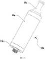
- the atomizer 10aincludes a shell 11a, an atomizing assembly 12a, a mouthpiece 13a at one end of the shell 11a, and an electrical connector 14a.
- the shell 11a, the mouthpiece 13a and the electrical connector 14acooperatively define an accommodating space 15a for receiving a liquid supply component 16a.
- the liquid supply component 16ais detachably arranged in the accommodating space 15a, and is replaceable.
- the liquid supply component 16aincludes a sealing structure 161a at one end.
- the sealing structure 161ais configured (i.e., structured and arranged) for sealing tobacco liquid in the liquid supply component 16a.
- the sealing structure 161amay be a hot melt plastic film, a silicone film, or a tin foil.
- a pricking meansis further provided in the accommodating space 15a. When the liquid supply component 16a is pushed into the accommodating space 15a, the pricking means pierces the sealing structure 161a, and the tobacco liquid in the liquid supply component 16a flows out to the atomizing assembly 12a.
- the mouthpiece 13a and the shell 11aare detachably connected, e.g., threadedly.
- the atomizing assembly 12ais arranged at one end adjacent to the electrical connector. Therefore, when the mouthpiece 13a is detached, the liquid supply component 16a can be taken out or placed in from one end of the shell 11a.
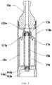
- a circular partition plate 111ais provided on an inner surface of the shell 11a.
- the pricking meansincludes a plurality of pricking pins 17a arranged on the partition plate 111a.
- the partition plate 111adefines a liquid inlet 112a.
- the liquid supply component 16a and the atomizing assembly 12aare arranged on two opposite sides of the partition plate 111a. The tobacco liquid can flow to the atomizing assembly 12a via the liquid inlet 112a.
- the electrical connector 14aincludes a connecting sleeve 141a, and a tubular electrode 142a coaxially arranged with the connecting sleeve 141a.
- the connecting sleeve 141ais insulated from the tubular electrode 142a.
- the connecting sleeve 142ais configured for fixedly connecting the shell 11a, and supporting the tubular electrode 142a.
- the atomizing assembly 12aincludes a heating wire 121a, and two ends of the heating wire 121a are respectively connected to the connecting sleeve 141a and the tubular electrode 142a.
- the connecting sleeve 141a and the tubular electrode 142aare electrically connected to other components for power.
- the mouthpiece 13aIn use, when replacing the liquid supply component 16a, the mouthpiece 13a is screwed off, the liquid supply component 16a is taken out, and a new liquid supply component 16a is placed into the shell 11a.
- the mouthpiece 13ais screwed on, the liquid supply component 16a is driven to move downwards, and then the pricking pins 17a pierce the sealing structure 161a, so that the tobacco liquid flows to the atomizing assembly 12a via the liquid inlet 112a.
- the atomizing assembly 12aheats the tobacco liquid to form aerosol.
- the atomizer 10aincludes an air pipe 18a.
- the connecting sleeve 141adefines a connecting hole 1411a, and an end of the air pipe 18a is detachably engaged in the connecting hole 1411a.
- the atomizer 10ais substantially similar to that of FIGS. 1-2 , except that the position of the atomizing assembly 12a and the engagement between the air pipe 18a and the connecting sleeve 141a.
- the atomizing assembly 12ais supported by the air pipe 18a, and is positioned between the mouthpiece 13a and the liquid supply component 16a.
- the connecting sleeve 141ais threadedly coupled with the air pipe 18a. In use, the connecting sleeve 141a is screwed off, the liquid supply component 16a is assembled into the accommodating space 15a, and then the connecting sleeve 141a is engaged with the air pipe 18a threadedly.
- the liquid supply component 16aincludes an inner tube 163a and an outer tube 162a nesting the inner tube 163a.
- the outer tube 162a and the inner tube 163acooperatively define an annular liquid storage chamber 164a.
- a first end of the liquid storage chamber 164ais closed, and an opposite second end of the liquid storage chamber 164a is sealed by the sealing structure 161a.
- Tobacco liquidis sealed in the liquid storage chamber 164a.
- the liquid supply component 16ais received in the 16a in such a manner that the inner tube 163a nests the air pipe 18a. Accordingly, it is very convenient to assemble and replace the liquid supply component 16a.
- the electronic cigarette 100aincludes the atomizer 10a and a power supply 20a.
- the atomizer 10ais configured for heating the tobacco liquid to form aerosol.
- the power supply 20ais adapted for supplying the atomizer 220a power.
- the liquid supply component 1bincludes a mouthpiece 12b at one end, a shell 11b, and an air pipe 14b extending from the mouthpiece 12b.
- the shell 11bnests the air pipe 14b.
- the air pipe 14b and the shell 11bcooperatively form an annular liquid storage chamber 15b.
- the liquid storage chamber 15bdefines an opening.
- a sealing structure 16bis provided at the opening, and is configured for sealing tobacco liquid in the liquid storage chamber 15b.
- the sealing structure 16bmay be a plastic film or a silicone film.
- the liquid supply component 1bfurther includes an engaging part 13b at one end of the shell 11b.
- the engaging part 13b and the shell 11bare integrally formed.
- the atomizer 10bincludes the liquid supply component 1b and an atomizing head 2b detachably connected with the liquid supply component 1b.
- the atomizing head 2bis configured for absorbing and heating tobacco liquid to form aerosol.
- the atomizing head 2bincludes a connecting element 23b, an air conducting pipe 24b, a pricking means 25b, an atomizing assembly 26b, a holder 21b, a fixing sleeve 22b, and a tubular electrode 27b.
- the connecting element 23bis configured for coupling with the engaging part 13b.
- the air conducting pipe 24bis configured to insert into the air pipe 14b.
- the pricking means 25bis configured to insert into the liquid storage chamber 15b, thus allowing tobacco liquid flowing out of the liquid storage chamber 15b.
- the atomizing assembly 26bis configured for absorbing and heating the tobacco liquid.
- the holder 21bis configured to fasten the air conducting pipe 24b, the pricking means 25b, and the atomizing assembly 26b.
- the tubular electrode 27bis arranged in the holder 21b.
- the fixing sleeve 22bis configured to fixedly connect with an external component.
- the fixing sleeve 22bis electrically conductive, and insulated from the tubular electrode 27b.
- Two opposite ends of the atomizing assembly 26bare connected to the tubular electrode 27b and the fixing sleeve 22b, respectively.
- the engaging part 13bis coupled to the connecting element 23b by interference fit.
- the connecting element 23b and the fixing sleeve 22bare engaged by screw threads.
- the holder 21bis threadedly fixed in the fixing sleeve 22b.
- the holder 21b and the fixing sleevecooperatively form an atomizing cavity 28b, and the atomizing assembly 26b is fixed by the holder 21b, and is positioned in the atomizing cavity 28b.
- a sealing ring 29bis further provided between the holder 21b and the fixing sleeve 22b to prevent tobacco liquid from leaking.
- the holder 21bfurther includes a flange 211b shielding the sealing ring 29b.
- the electronic cigarette 100bincludes the atomizer 20b and a power supply 30b connected with the atomizer 20b.
- a liquid supply component 1 for an electronic cigaretteis provided.
- the liquid supply component 1is configured (i.e., structured and arranged) for storing tobacco liquid.
- the liquid supply component 1includes a cylindrical shell 11 defining a liquid storage chamber 12.
- the shell 11includes an end wall 13 at one end, and an opening 14 at the other end.
- the end wall 13is configured for sealing the liquid storage chamber 12.
- a sealing structure 15is provided at the opening 14 to seal the liquid storage chamber 12.
- An air pipe 16is provided in the liquid storage chamber 12, and is oriented along an axis of the shell 11. The air pipe 16 extends from the end wall 13 to the opening 14.
- An annular liquid storage spaceis defined between the air pipe 16 and the shell 11.
- the air pipe 16defines an air passage 17 extending through the end wall 13 to form a mouthpiece.
- the air pipe 16 and the shell 11are coaxially arranged.
- a rib plate 18is provided around the air pipe 16, and is configured for supporting the air pipe 16.
- the sealing structure 15Before filling the tobacco liquid, one end of the liquid supply component 1 is open. After filling the tobacco liquid into the liquid storage chamber 12 between the shell 11 and the air pipe 16, the sealing structure 15 is used to seal the opening 14 of the shell 11.
- the sealing structure 15may be a thin film, for example, a hot melt adhesive membrane. The sealing structure 15 is pressed onto one end of the shell 11 and the air pipe 16, and is heated so as to firmly adhere to the shell 11 and the air pipe 16. In this way, the tobacco liquid is sealed in the liquid storage chamber 12.
- the liquid supply component 1is assembled into an electronic cigarette (described in detail later).
- an anti-slip structureis provided on an external surface of the shell 11, and the shell and a housing of the electronic cigarette is coupled by interference fit.
- the electronic cigarette 100includes a housing 110, a power supply 120, an atomizing assembly 130, and a liquid absorbing component 140.
- the liquid supply component 1is arranged at one end of the housing 110.
- One part of the shell 11 of the liquid supply component 1is positioned in the housing 110, and is engaged with the housing 110 by interference fit. The other part of the shell 11 exposes from the housing 110.
- a space 150is provided between the liquid supply component 1 and the liquid absorbing component 140. The space 150 is for receiving the liquid supply component 1 when the liquid supply component 1 is pushed into the housing 110.
- a plurality of pricking pins 160are provided in the space 150. The pricking pins 160 are configured for inserting into an end of the liquid supply component 1 via the sealing structure 15, so that the tobacco liquid sealed in the liquid supply component 1 flows to the liquid absorbing component 140, and then to the atomizing assembly 130.
- the housing 110is integrally formed and is cylindrical.
- a length of the space 150 in a central axis of the housing 110is larger than or equal to that of a part of the liquid supply component 1, which protrudes from the housing 110. That is, when the liquid supply component 1 is pushed into the housing 110, the liquid supply component 1 is completely located in the housing 110.
- the liquid supply component 1includes a flange 111 at one end.
- the flange 111abuts against an end of the housing 110.
- a diameter of the flangeis equal to that of the housing 110, so that an outer surface of the flange 111 aligns with that of the housing 110.
- the liquid absorbing component 140is configured for absorbing the tobacco liquid from the liquid supply component 1.
- the liquid absorbing component 140includes a frame 141 and a porous body 142 in the frame 141.
- the porous body 142is wrapped around the atomizing assembly 130, so that the porous body 142 provides the atomizing assembly 130 the tobacco liquid for atomizing.
- the frame 141includes a buffer area 1411 adjacent to liquid supply component 1 and a liquid storage area 1412 away from the liquid supply component 1.
- the porous body 142is arranged in both of the buffer area 1411 and the liquid storage area 1412. At least one through hole 1413 connects the buffer area 1411 and the liquid storage area 1412. The tobacco liquid flows to the buffer area 1411 from the liquid supply component 1.
- the buffer area 1411absorbs enough tobacco liquid, the tobacco liquid flows to the liquid storage area 1412 via the through hole 1413, is then conveyed to the atomizing assembly 130.
- the design of the buffer area 1411 and the liquid storage area 1412can prevent the atomizing assembly 130 from leaking.
- the atomizing assembly 130includes a glass fiber tube 131, and a glass fiber core 132 supported by the glass fiber core 132, and a heating wire wound around the glass fiber core 132.
- the tobacco liquidis conveyed to the glass fiber core 132 from the porous body 142 by capillary action, and is then heated to form aerosol by the heating wire 133.
- the glass fiber tube 131defines an atomizing cavity 134, and aerosol is expelled from the atomizing cavity 134.
- the frame 141further includes a hollow air guiding rod 1414 protruding therefrom.
- the air guiding rod 1414communicates with the atomizing cavity 134, and is capable of inserting into the air pipe 16 of the liquid supply component 1.
- the pricking pins 160are arranged on a spacer 170.
- the spacer 170nests the air guiding rod 1414.
- the spacer 170is coaxially arranged with the liquid supply component 1.
- the spacer 170is annular shaped, and defines a central hole 171.
- the pricking pins 160are arranged around the central hole 171.
- the spacer 170further defines a plurality of holes 172 adjacent to the pricking pins 160.
- the holes 172allow the tobacco liquid to flow into the liquid absorbing component 140.
- the pricking pins 160define one or more grooves 161 for facilitating the flow of the tobacco liquid.
- the pricking pins 160may be hollow, so that the tobacco liquid may flow into the liquid absorbing component 140 by passing through the pricking pins 160.
- the electronic cigarette 200includes a housing 210.
- the housing 210has a first part for receiving an atomizer 220, and a second part for accommodating a battery rod 230.
- the atomizer 220is atomizing tobacco liquid, and the battery rod 230 is adapted for supplying the atomizer 220 power.
- the atomizer 220is detachably connected to the battery rod 230, for example, threadedly.
Landscapes
- Health & Medical Sciences (AREA)
- Engineering & Computer Science (AREA)
- Animal Behavior & Ethology (AREA)
- Anesthesiology (AREA)
- Biomedical Technology (AREA)
- Heart & Thoracic Surgery (AREA)
- Hematology (AREA)
- Life Sciences & Earth Sciences (AREA)
- General Health & Medical Sciences (AREA)
- Public Health (AREA)
- Veterinary Medicine (AREA)
- Pulmonology (AREA)
- Bioinformatics & Cheminformatics (AREA)
- Electrostatic Spraying Apparatus (AREA)
Description
- The present invention relates to electronic cigarettes, and particularly to an atomizer and an electronic cigarette using same.
- Nowadays, electronic cigarettes mainly include disposable electronic cigarettes and refillable electronic cigarette. The disposable electronic cigarettes are not environmental-friendly because they are discarded after used. The refillable electronic cigarettes can be used repeatedly. After tobacco liquid in the refillable electronic cigarettes is used up, the user of the electronic cigarettes can refill the tobacco liquid by themselves. Accordingly, the refillable electronic cigarettes are more environmental-friendly. However, it is inconvenient to refill the tobacco liquid, and the tobacco liquid may pollute clothes of the users during this process.
- What is needed, therefore, is an atomizer and an electronic cigarette using same, which can overcome the above shortcomings. Atomizer and/or electronic cigarettes for liquids with sealed cartridges are known from prior art documents such as
WO 2013/159245 A1 ,US 2011/277757 A1 ,US 2010/00613 A1 ,EP 2 617 303 A1 andCN 202 407 082 U . - The invention is defined in
independent claim 1. - An exemplary atomizer includes a liquid supply component, an atomizing assembly, and a pricking means. The liquid supply component is configured for storing tobacco liquid. The liquid supply component has a sealing means for sealing the tobacco liquid therein. The pricking means for pricking the sealing structure so that the tobacco liquid flows to the atomizing assembly. The atomizing assembly is configured for heating the tobacco liquid to form aerosol.
- Many aspects of the present disclosure can be better understood with reference to the following drawings. The components in the drawings are not necessarily drawn to scale, the emphasis instead being placed upon clearly illustrating the principles of the present disclosure. Moreover, in the drawings, like reference numerals designate corresponding parts throughout the several views.
FIG. 1 is a perspective view of an atomizer according to a first embodiment.FIG. 2 is a cross-sectional view of the atomizer ofFIG. 1 .FIG. 3 is a cross-sectional view of an atomizer according to a second embodiment.FIG. 4 is a cross-sectional view of a liquid supply component inFIGS. 2-3 .FIG. 5 is a perspective view of an electronic cigarette according to a third embodiment.FIG. 6 is a perspective view of a liquid supply component according to a fourth embodiment.FIG. 7 is a cross-sectional view of the liquid supply component ofFIG. 6 .FIG. 8 is a perspective view of an atomizer according to a fifth embodiment.FIG. 9 is a cross-sectional view of the atomizer ofFIG. 8 .FIG. 10 is an exploded perspective view of the atomizer ofFIG. 8 .FIG. 11 is a perspective view of an electronic cigarette according to a sixth embodiment.FIG. 12 is a perspective cut-off view of a liquid supply component according to a seventh embodiment.FIG. 13 is a perspective view of the liquid supply component ofFIG. 12 .FIG. 14 is a perspective view of an electronic cigarette according to an eighth embodiment.FIG. 15 is a cross-sectional view of the electronic cigarette ofFIG. 14 .FIG. 16 is a cross-sectional view of the electronic cigarette in a working state ofFIG. 14 .FIG. 17 is an exploded perspective view of the electronic cigarette ofFIG. 14 .FIG. 18 is a perspective cut-off view of a liquid absorbing component in the electronic cigarette ofFIG. 14 .FIG. 19 is a perspective view of a spacer in the electronic cigarette ofFIG. 14 .FIG. 20 is a perspective view an electronic cigarette according to a ninth embodiment.- It will be appreciated that for simplicity and clarity of illustration, where appropriate, reference numerals have been repeated among the different figures to indicate corresponding or analogous elements. In addition, numerous specific details are set forth in order to provide a thorough understanding of the embodiments described herein. However, it will be understood by those of ordinary skill in the art that the embodiments described herein can be practiced without these specific details. In other instances, methods, procedures and components have not been described in detail so as not to obscure the related relevant feature being described. Also, the description is not to be considered as limiting the scope of the embodiments described herein. The drawings are not necessarily to scale and the proportions of certain parts have been exaggerated to better illustrate details and features of the present disclosure.
- The disclosure is illustrated by way of example and not by way of limitation in the figures of the accompanying drawings in which like references indicate similar elements. It should be noted that references to "an" or "one" embodiment in this disclosure are not necessarily to the same embodiment, and such references mean at least one.
- Several definitions that apply throughout this disclosure will now be presented.
- The term "outside" refers to a region that is beyond the outermost confines of a physical object. The term "inside" indicates that at least a portion of a region is partially contained within a boundary formed by the object. The term "substantially" is defined to be essentially conforming to the particular dimension, shape or other word that substantially modifies, such that the component need not be exact. For example, substantially cylindrical means that the object resembles a cylinder, but can have one or more deviations from a true cylinder. The term "comprising," when utilized, means "including, but not necessarily limited to"; it specifically indicates open-ended inclusion or membership in the so-described combination, group, series and the like.
- Referring to
FIGS. 1-2 , anatomizer 10a according to a first embodiment is shown. Theatomizer 10a includes ashell 11a, an atomizingassembly 12a, amouthpiece 13a at one end of theshell 11a, and anelectrical connector 14a. Theshell 11a, themouthpiece 13a and theelectrical connector 14a cooperatively define anaccommodating space 15a for receiving aliquid supply component 16a. Theliquid supply component 16a is detachably arranged in theaccommodating space 15a, and is replaceable. Theliquid supply component 16a includes asealing structure 161a at one end. Thesealing structure 161a is configured (i.e., structured and arranged) for sealing tobacco liquid in theliquid supply component 16a. Thesealing structure 161a may be a hot melt plastic film, a silicone film, or a tin foil. A pricking means is further provided in theaccommodating space 15a. When theliquid supply component 16a is pushed into theaccommodating space 15a, the pricking means pierces the sealingstructure 161a, and the tobacco liquid in theliquid supply component 16a flows out to theatomizing assembly 12a. - The
mouthpiece 13a and theshell 11a are detachably connected, e.g., threadedly. Theatomizing assembly 12a is arranged at one end adjacent to the electrical connector. Therefore, when themouthpiece 13a is detached, theliquid supply component 16a can be taken out or placed in from one end of theshell 11a. Acircular partition plate 111a is provided on an inner surface of theshell 11a. In the present embodiment, the pricking means includes a plurality of prickingpins 17a arranged on thepartition plate 111a. Thepartition plate 111a defines aliquid inlet 112a. Theliquid supply component 16a and theatomizing assembly 12a are arranged on two opposite sides of thepartition plate 111a. The tobacco liquid can flow to theatomizing assembly 12a via theliquid inlet 112a. - In the present embodiment, the
electrical connector 14a includes a connectingsleeve 141a, and atubular electrode 142a coaxially arranged with the connectingsleeve 141a. The connectingsleeve 141a is insulated from thetubular electrode 142a. The connectingsleeve 142a is configured for fixedly connecting theshell 11a, and supporting thetubular electrode 142a. Theatomizing assembly 12a includes aheating wire 121a, and two ends of theheating wire 121a are respectively connected to the connectingsleeve 141a and thetubular electrode 142a. The connectingsleeve 141a and thetubular electrode 142a are electrically connected to other components for power. - In use, when replacing the
liquid supply component 16a, themouthpiece 13a is screwed off, theliquid supply component 16a is taken out, and a newliquid supply component 16a is placed into theshell 11a. Themouthpiece 13a is screwed on, theliquid supply component 16a is driven to move downwards, and then the pricking pins 17a pierce the sealingstructure 161a, so that the tobacco liquid flows to theatomizing assembly 12a via theliquid inlet 112a. When theatomizer 10a is connected to a power supply device, theatomizing assembly 12a heats the tobacco liquid to form aerosol. - Referring to
FIG. 3 , theatomizer 10a according to a second embodiment is shown. Theatomizer 10a includes anair pipe 18a. The connectingsleeve 141a defines a connecting hole 1411a, and an end of theair pipe 18a is detachably engaged in the connecting hole 1411a. Theatomizer 10a is substantially similar to that ofFIGS. 1-2 , except that the position of theatomizing assembly 12a and the engagement between theair pipe 18a and the connectingsleeve 141a. Theatomizing assembly 12a is supported by theair pipe 18a, and is positioned between themouthpiece 13a and theliquid supply component 16a. The connectingsleeve 141a is threadedly coupled with theair pipe 18a. In use, the connectingsleeve 141a is screwed off, theliquid supply component 16a is assembled into theaccommodating space 15a, and then the connectingsleeve 141a is engaged with theair pipe 18a threadedly. - Referring to
FIG. 4 , theliquid supply component 16a includes aninner tube 163a and anouter tube 162a nesting theinner tube 163a. Theouter tube 162a and theinner tube 163a cooperatively define an annularliquid storage chamber 164a. A first end of theliquid storage chamber 164a is closed, and an opposite second end of theliquid storage chamber 164a is sealed by the sealingstructure 161a. Tobacco liquid is sealed in theliquid storage chamber 164a. In use, theliquid supply component 16a is received in the 16a in such a manner that theinner tube 163a nests theair pipe 18a. Accordingly, it is very convenient to assemble and replace theliquid supply component 16a. - Referring to
FIG. 5 , anelectronic cigarette 100a according to a third embodiment is shown. Theelectronic cigarette 100a includes theatomizer 10a and apower supply 20a. Theatomizer 10a is configured for heating the tobacco liquid to form aerosol. Thepower supply 20a is adapted for supplying the atomizer 220a power. - Referring to
FIGS. 6-7 , aliquid supply component 1b according to a fourth embodiment. Theliquid supply component 1b includes amouthpiece 12b at one end, ashell 11b, and anair pipe 14b extending from themouthpiece 12b. Theshell 11b nests theair pipe 14b. Theair pipe 14b and theshell 11b cooperatively form an annularliquid storage chamber 15b. Theliquid storage chamber 15b defines an opening. A sealingstructure 16b is provided at the opening, and is configured for sealing tobacco liquid in theliquid storage chamber 15b. The sealingstructure 16b may be a plastic film or a silicone film. - The
liquid supply component 1b further includes anengaging part 13b at one end of theshell 11b. Theengaging part 13b and theshell 11b are integrally formed. - Referring to
FIGS. 8-10 , anatomizer 10b according to a fifth embodiment is shown. Theatomizer 10b includes theliquid supply component 1b and anatomizing head 2b detachably connected with theliquid supply component 1b. Theatomizing head 2b is configured for absorbing and heating tobacco liquid to form aerosol. - The
atomizing head 2b includes a connectingelement 23b, anair conducting pipe 24b, a pricking means 25b, anatomizing assembly 26b, aholder 21b, a fixingsleeve 22b, and atubular electrode 27b. The connectingelement 23b is configured for coupling with theengaging part 13b. Theair conducting pipe 24b is configured to insert into theair pipe 14b. The pricking means 25b is configured to insert into theliquid storage chamber 15b, thus allowing tobacco liquid flowing out of theliquid storage chamber 15b. Theatomizing assembly 26b is configured for absorbing and heating the tobacco liquid. Theholder 21b is configured to fasten theair conducting pipe 24b, the pricking means 25b, and theatomizing assembly 26b. Thetubular electrode 27b is arranged in theholder 21b. The fixingsleeve 22b is configured to fixedly connect with an external component. The fixingsleeve 22b is electrically conductive, and insulated from thetubular electrode 27b. Two opposite ends of theatomizing assembly 26b are connected to thetubular electrode 27b and the fixingsleeve 22b, respectively. Theengaging part 13b is coupled to the connectingelement 23b by interference fit. The connectingelement 23b and the fixingsleeve 22b are engaged by screw threads. - The
holder 21b is threadedly fixed in the fixingsleeve 22b. Theholder 21b and the fixing sleeve cooperatively form anatomizing cavity 28b, and theatomizing assembly 26b is fixed by theholder 21b, and is positioned in theatomizing cavity 28b. - In the present embodiment, a sealing
ring 29b is further provided between theholder 21b and the fixingsleeve 22b to prevent tobacco liquid from leaking. Theholder 21b further includes aflange 211b shielding the sealingring 29b. - Referring to
FIG. 11 , an electronic cigarette 100b according to a sixth embodiment is shown. The electronic cigarette 100b includes theatomizer 20b and apower supply 30b connected with theatomizer 20b. - Referring to
FIGS. 12-13 , aliquid supply component 1 for an electronic cigarette is provided. Theliquid supply component 1 is configured (i.e., structured and arranged) for storing tobacco liquid. Theliquid supply component 1 includes acylindrical shell 11 defining aliquid storage chamber 12. Theshell 11 includes anend wall 13 at one end, and anopening 14 at the other end. Theend wall 13 is configured for sealing theliquid storage chamber 12. A sealingstructure 15 is provided at theopening 14 to seal theliquid storage chamber 12. Anair pipe 16 is provided in theliquid storage chamber 12, and is oriented along an axis of theshell 11. Theair pipe 16 extends from theend wall 13 to theopening 14. An annular liquid storage space is defined between theair pipe 16 and theshell 11. - The
air pipe 16 defines anair passage 17 extending through theend wall 13 to form a mouthpiece. In the present embodiment, theair pipe 16 and theshell 11 are coaxially arranged. Further, arib plate 18 is provided around theair pipe 16, and is configured for supporting theair pipe 16. - Before filling the tobacco liquid, one end of the
liquid supply component 1 is open. After filling the tobacco liquid into theliquid storage chamber 12 between theshell 11 and theair pipe 16, the sealingstructure 15 is used to seal theopening 14 of theshell 11. For easy production, the sealingstructure 15 may be a thin film, for example, a hot melt adhesive membrane. The sealingstructure 15 is pressed onto one end of theshell 11 and theair pipe 16, and is heated so as to firmly adhere to theshell 11 and theair pipe 16. In this way, the tobacco liquid is sealed in theliquid storage chamber 12. - In use, the
liquid supply component 1 is assembled into an electronic cigarette (described in detail later). To prevent the slippage of theliquid supply component 1 during use, an anti-slip structure is provided on an external surface of theshell 11, and the shell and a housing of the electronic cigarette is coupled by interference fit. - Referring to
FIGS. 14-17 , anelectronic cigarette 100 is shown. Theelectronic cigarette 100 includes ahousing 110, apower supply 120, anatomizing assembly 130, and a liquid absorbingcomponent 140. Theliquid supply component 1 is arranged at one end of thehousing 110. One part of theshell 11 of theliquid supply component 1 is positioned in thehousing 110, and is engaged with thehousing 110 by interference fit. The other part of theshell 11 exposes from thehousing 110. Aspace 150 is provided between theliquid supply component 1 and the liquid absorbingcomponent 140. Thespace 150 is for receiving theliquid supply component 1 when theliquid supply component 1 is pushed into thehousing 110. A plurality of prickingpins 160 are provided in thespace 150. The pricking pins 160 are configured for inserting into an end of theliquid supply component 1 via the sealingstructure 15, so that the tobacco liquid sealed in theliquid supply component 1 flows to the liquid absorbingcomponent 140, and then to theatomizing assembly 130. - In the present embodiment, the
housing 110 is integrally formed and is cylindrical. A length of thespace 150 in a central axis of thehousing 110 is larger than or equal to that of a part of theliquid supply component 1, which protrudes from thehousing 110. That is, when theliquid supply component 1 is pushed into thehousing 110, theliquid supply component 1 is completely located in thehousing 110. - The
liquid supply component 1 includes aflange 111 at one end. When theliquid supply component 1 is engaged in thehousing 110, theflange 111 abuts against an end of thehousing 110. A diameter of the flange is equal to that of thehousing 110, so that an outer surface of theflange 111 aligns with that of thehousing 110. - The liquid absorbing
component 140 is configured for absorbing the tobacco liquid from theliquid supply component 1. The liquid absorbingcomponent 140 includes aframe 141 and aporous body 142 in theframe 141. Theporous body 142 is wrapped around theatomizing assembly 130, so that theporous body 142 provides theatomizing assembly 130 the tobacco liquid for atomizing. In the present embodiment, theframe 141 includes abuffer area 1411 adjacent toliquid supply component 1 and aliquid storage area 1412 away from theliquid supply component 1. Theporous body 142 is arranged in both of thebuffer area 1411 and theliquid storage area 1412. At least one throughhole 1413 connects thebuffer area 1411 and theliquid storage area 1412. The tobacco liquid flows to thebuffer area 1411 from theliquid supply component 1. After thebuffer area 1411 absorbs enough tobacco liquid, the tobacco liquid flows to theliquid storage area 1412 via the throughhole 1413, is then conveyed to theatomizing assembly 130. The design of thebuffer area 1411 and theliquid storage area 1412 can prevent theatomizing assembly 130 from leaking. - The
atomizing assembly 130 includes aglass fiber tube 131, and aglass fiber core 132 supported by theglass fiber core 132, and a heating wire wound around theglass fiber core 132. The tobacco liquid is conveyed to theglass fiber core 132 from theporous body 142 by capillary action, and is then heated to form aerosol by theheating wire 133. Theglass fiber tube 131 defines anatomizing cavity 134, and aerosol is expelled from theatomizing cavity 134. - The
frame 141 further includes a hollow air guiding rod 1414 protruding therefrom. The air guiding rod 1414 communicates with theatomizing cavity 134, and is capable of inserting into theair pipe 16 of theliquid supply component 1. - Referring to
FIG. 19 , in the present embodiment, the pricking pins 160 are arranged on aspacer 170. Thespacer 170 nests the air guiding rod 1414. Thespacer 170 is coaxially arranged with theliquid supply component 1. Thespacer 170 is annular shaped, and defines acentral hole 171. The pricking pins 160 are arranged around thecentral hole 171. Thespacer 170 further defines a plurality ofholes 172 adjacent to the pricking pins 160. Theholes 172 allow the tobacco liquid to flow into the liquid absorbingcomponent 140. Further, the pricking pins 160 define one ormore grooves 161 for facilitating the flow of the tobacco liquid. In other embodiments, the pricking pins 160 may be hollow, so that the tobacco liquid may flow into the liquid absorbingcomponent 140 by passing through the pricking pins 160. - Referring to
FIG. 20 , anotherelectronic cigarette 200 is shown. Theelectronic cigarette 200 includes ahousing 210. Thehousing 210 has a first part for receiving anatomizer 220, and a second part for accommodating abattery rod 230. Theatomizer 220 is atomizing tobacco liquid, and thebattery rod 230 is adapted for supplying theatomizer 220 power. Theatomizer 220 is detachably connected to thebattery rod 230, for example, threadedly. - It is understood that the above-described embodiments are intended to illustrate rather than limit the disclosure. Variations may be made to the embodiments and methods without departing from the scope of the disclosure. Accordingly, it is appropriate that the appended claims be construed broadly and in a manner consistent with the scope of the disclosure.
Claims (18)
- An atomizer, comprising:a liquid supply component (16a) configured for storing tobacco liquid, the liquid supply component having a sealing structure (161a) for sealing the tobacco liquid therein;an atomizing assembly (12a); a pricking means for pricking the sealing structure so that the tobacco liquid flows to the atomizing assembly, the atomizing assembly configured for heating the tobacco liquid to form aerosol; anda shell (11a), the atomizer being arranged in the shell; wherein the shell comprises a circular partition plate (111a) provided on an inner surface of the shell, the pricking means comprises a plurality of pricking pins (17a) arranged on the partition plate,characterized in that the liquid supply component and the atomizing assembly are arranged on two opposite sides of the partition plate, and the partition plate defines a liquid inlet (112a) via which the tobacco liquid flows to the atomizing assembly.
- The atomizer of claim 1, further comprising:a mouthpiece at a first end of the shell;an electrical connector at an opposite second end of the shell, wherein the shell, the mouthpiece, and the electrical connector cooperatively define an accommodating space, the liquid supply component is detachably received in the accommodating space, and the pricking means is received in the accommodating space.
- The atomizer of claim 2, wherein the mouthpiece is detachably connected with the shell, and the liquid supply component is arranged between the mouthpiece and the atomizer.
- The atomizer of claim 2, further comprising an air pipe, wherein the atomizing assembly is supported by a first end of the air pipe, and is arranged between the mouthpiece and the liquid supply component; the electrical connector comprises a connecting sleeve, the connecting sleeve defines a connecting hole, and an opposite second end of the air pipe is detachably engaged in the connecting hole.
- The atomizer of claim 1, wherein the liquid supply component comprises a mouthpiece at one end, a shell extending from the mouthpiece, and an air pipe extending from the mouthpiece; the shell nests the air pipe, the shell is coaxially arranged with the air pipe, the air pipe and the shell cooperatively define an annular liquid storage chamber for storing the tobacco liquid, the liquid storage chamber defines an opening, and the sealing structure seals the opening.
- The atomizer of claim 5, further comprising a rib plate (18) provided around the air pipe (16) for supporting the air pipe (16).
- The atomizer of claim 5, wherein the sealing structure is a hot melt adhesive membrane.
- The atomizer of claim 5, wherein the liquid supply component further comprises an engaging part at an opposite one end of the shell, the engaging part and the shell are integrally formed.
- The atomizer of claim 8, further comprising:a connecting element configured for coupling with the engaging part; andan air conducting pipe configured to insert into the air pipe.
- The atomizer of claim 9, further comprising:a holder for fixing the air conducting pipe, the pricking means, the atomizing assembly;a fixing sleeve connected to the connecting element; anda tubular electrode arranged in the holder, the tubular electrode being electrically insulated from the fixing sleeve.
- The atomizer of claim 10, wherein the holder is fixed in the fixing sleeve, the holder and the fixing sleeve cooperatively define an atomizing cavity, and the atomizing assembly is fixed by the holder, and is positioned in the atomizing cavity.
- An electronic cigarette, comprising:an atomizer according to claim 1; anda power supply configured for providing the atomizer power.
- The electronic cigarette of claim 12, further comprising:a housing, the atomizing assembly and the power supply being received in the housing, the liquid supply component being arranged at one end of the housing; anda liquid absorbing component received in the housing;wherein the liquid absorbing component and the main body cooperatively define a space, the pricking means is positioned in the space; a first part of the main body is accommodated in the housing, and a second part of the main body exposes from the housing; wherein the liquid absorbing component and the main body are adapted such that, when the second part of the main body is pushed into the housing, the pricking means pricks the sealing structure, so that the tobacco liquid flows to the liquid absorbing component, and is then conveyed to the atomizing assembly.
- The electronic cigarette of claim 13, wherein a length of the space along an axis of the housing is larger than or equal to that of the second part of the main body.
- The electronic cigarette of claim 13, wherein the liquid absorbing component comprises a frame and a porous body in the frame, and the porous body is wrapped around the atomizing assembly.
- The electronic cigarette of claim 13, wherein the pricking pins (160) of the pricking means are arranged on a spacer (170) which defines a plurality of holes adjacent to the pricking pins (160), the holes allowing the tobacco liquid to flow into the liquid absorbing component (140).
- The electronic cigarette of claim 13, wherein the pricking pins (160) of the pricking means further define one or more groves (161) for facilitating the tobacco liquid to flow into the liquid absorbing component (140).
- The electronic cigarette of claim 13, wherein the pricking pins (160) of the pricking means are hollow so as to facilitate the tobacco liquid to flow into the liquid absorbing component (140) by passing through the pricking pins (160).
Applications Claiming Priority (3)
| Application Number | Priority Date | Filing Date | Title |
|---|---|---|---|
| CN201420166373.1UCN203851809U (en) | 2014-04-08 | 2014-04-08 | Liquid supply component for electronic tobacco and electronic tobacco |
| CN201420348724.0UCN204070533U (en) | 2014-06-27 | 2014-06-27 | Integral type cigarette bullet, the electronic smoke atomizer with this cigarette bullet and electronic cigarette |
| CN201420372002.9UCN204070540U (en) | 2014-07-08 | 2014-07-08 | Atomising device and electronic cigarette |
Publications (2)
| Publication Number | Publication Date |
|---|---|
| EP2929903A1 EP2929903A1 (en) | 2015-10-14 |
| EP2929903B1true EP2929903B1 (en) | 2018-05-09 |
Family
ID=52874945
Family Applications (1)
| Application Number | Title | Priority Date | Filing Date |
|---|---|---|---|
| EP15161550.7AActiveEP2929903B1 (en) | 2014-04-08 | 2015-03-28 | Atomizer and electronic cigarette |
Country Status (2)
| Country | Link |
|---|---|
| US (1) | US9848649B2 (en) |
| EP (1) | EP2929903B1 (en) |
Families Citing this family (76)
| Publication number | Priority date | Publication date | Assignee | Title |
|---|---|---|---|---|
| US20160345631A1 (en) | 2005-07-19 | 2016-12-01 | James Monsees | Portable devices for generating an inhalable vapor |
| US10279934B2 (en) | 2013-03-15 | 2019-05-07 | Juul Labs, Inc. | Fillable vaporizer cartridge and method of filling |
| USD768914S1 (en)* | 2013-08-16 | 2016-10-11 | Huizhou Kimree Technology Co., Ltd. Shenzhen Branch | Electronic cigarette |
| US10039321B2 (en) | 2013-11-12 | 2018-08-07 | Vmr Products Llc | Vaporizer |
| US20160366947A1 (en) | 2013-12-23 | 2016-12-22 | James Monsees | Vaporizer apparatus |
| US10159282B2 (en) | 2013-12-23 | 2018-12-25 | Juul Labs, Inc. | Cartridge for use with a vaporizer device |
| US10058129B2 (en) | 2013-12-23 | 2018-08-28 | Juul Labs, Inc. | Vaporization device systems and methods |
| DE202014011260U1 (en) | 2013-12-23 | 2018-11-13 | Juul Labs Uk Holdco Limited | Systems for an evaporation device |
| US10076139B2 (en) | 2013-12-23 | 2018-09-18 | Juul Labs, Inc. | Vaporizer apparatus |
| USD825102S1 (en) | 2016-07-28 | 2018-08-07 | Juul Labs, Inc. | Vaporizer device with cartridge |
| USD842536S1 (en) | 2016-07-28 | 2019-03-05 | Juul Labs, Inc. | Vaporizer cartridge |
| JP1518262S (en)* | 2014-02-24 | 2015-02-23 | ||
| USD759297S1 (en)* | 2014-02-25 | 2016-06-14 | Kimree Hi-Tech Inc. | Electronic cigarette |
| USD766503S1 (en)* | 2014-02-25 | 2016-09-13 | Kimree Hi-Tech Inc. | Electronic cigarette rod |
| USD758647S1 (en)* | 2014-02-25 | 2016-06-07 | Kimree Hi-Tech | Electronic cigarette |
| JP1518251S (en)* | 2014-02-25 | 2015-02-23 | ||
| USD765309S1 (en)* | 2014-02-25 | 2016-08-30 | Qiuming Liu | Electronic cigarette |
| USD765307S1 (en)* | 2014-02-25 | 2016-08-30 | Qiuming Liu | Electronic cigarette |
| JP1518244S (en)* | 2014-02-25 | 2015-02-23 | ||
| EP2946679B1 (en)* | 2014-04-28 | 2019-09-25 | Shenzhen First Union Technology Co., Ltd. | Atomizer and electronic cigarette having same |
| CN204070555U (en)* | 2014-07-30 | 2015-01-07 | 深圳市合元科技有限公司 | For atomizer and the electronic cigarette of electronic cigarette |
| USD780372S1 (en)* | 2014-08-20 | 2017-02-28 | Huizhou Kimree Technology Co., Ltd | Electronic cigarette atomizer |
| US20160278163A1 (en)* | 2014-10-10 | 2016-09-22 | Shenzhen Smoore Technology Limited | Inhaler and atomizing assembly thereof |
| WO2016082178A1 (en)* | 2014-11-28 | 2016-06-02 | 惠州市吉瑞科技有限公司 | Atomizing component and electronic cigarette |
| MX394125B (en) | 2014-12-05 | 2025-03-24 | Juul Labs Inc | CALIBRATED DOSE CONTROL |
| CN107105766B (en)* | 2014-12-18 | 2020-05-05 | Jt国际公司 | Containers for aerosol generating equipment |
| USD796112S1 (en)* | 2015-02-18 | 2017-08-29 | Nicoventures Holdings Limited | Electronic cigarette |
| PL3273811T3 (en)* | 2015-03-27 | 2020-06-01 | Philip Morris Products S.A. | Aerosol-generating system comprising integrated piercing element |
| IL279264B (en) | 2015-05-06 | 2022-09-01 | Altria Client Services Llc | A non-flammable smoking device and its components |
| US20160332754A1 (en)* | 2015-05-13 | 2016-11-17 | Fontem Holdings 4 B.V. | Device for refilling electronic cigarette cartridge |
| USD783117S1 (en)* | 2015-09-15 | 2017-04-04 | Cutting Edge Products, Inc. | Electric stun gun |
| USD771219S1 (en)* | 2015-09-15 | 2016-11-08 | Cutting Edge Products, Inc | Electric stun gun having an electric cigarette-shaped mouthpiece |
| USD824586S1 (en)* | 2015-09-25 | 2018-07-31 | Avanzato Technology Corp. | Vapor tube |
| USD828623S1 (en)* | 2015-09-25 | 2018-09-11 | Avanzato Technology Corp. | Foil tank |
| EP3383460B1 (en)* | 2015-11-30 | 2020-07-15 | Philip Morris Products S.a.s. | Non-combustible smoking device and elements thereof |
| EP3386323B1 (en) | 2015-12-18 | 2021-02-03 | JT International S.A. | Personal vaporizer device |
| USD800381S1 (en)* | 2016-01-28 | 2017-10-17 | Shenzhen Smoore Technology Limited | Atomizer for electronic cigarettes |
| CO2018009342A2 (en) | 2016-02-11 | 2018-09-20 | Juul Labs Inc | Secure fixing cartridges for vaporizing devices |
| EP3413960B1 (en) | 2016-02-11 | 2021-03-31 | Juul Labs, Inc. | Fillable vaporizer cartridge and method of filling |
| US10405582B2 (en) | 2016-03-10 | 2019-09-10 | Pax Labs, Inc. | Vaporization device with lip sensing |
| EP3435793B1 (en)* | 2016-03-31 | 2020-07-08 | Philip Morris Products S.a.s. | Aerosol generating system with separate capsule and vaporizing unit |
| USD920567S1 (en)* | 2016-05-18 | 2021-05-25 | Gsw Creative Corporation | Electronic cigarette |
| USD849996S1 (en) | 2016-06-16 | 2019-05-28 | Pax Labs, Inc. | Vaporizer cartridge |
| CN206808661U (en)* | 2016-06-22 | 2017-12-29 | 深圳市合元科技有限公司 | Oil storage cup and atomizer for atomizer |
| USD836541S1 (en) | 2016-06-23 | 2018-12-25 | Pax Labs, Inc. | Charging device |
| USD851830S1 (en) | 2016-06-23 | 2019-06-18 | Pax Labs, Inc. | Combined vaporizer tamp and pick tool |
| CA3031418C (en) | 2016-07-22 | 2023-03-28 | Nicoventures Holdings Limited | Storage case |
| GB201616430D0 (en)* | 2016-09-28 | 2016-11-09 | Nicoventures Holdings Limited | Liquid storage tank for a vapour provision system |
| US20180110941A1 (en)* | 2016-10-21 | 2018-04-26 | Brian Smith | Pearl precision medical dosing vaporizer fully interchangeable |
| US10433585B2 (en) | 2016-12-28 | 2019-10-08 | Altria Client Services Llc | Non-combustible smoking systems, devices and elements thereof |
| US10015991B1 (en) | 2016-12-29 | 2018-07-10 | Altria Client Services Llc | Hybrid E-vaping cartridge, E-vaping device including a hybrid E-vaping cartridge, and method of making thereof |
| USD853635S1 (en)* | 2017-02-23 | 2019-07-09 | Shenzhen Smoore Technology Limited | Atomizer for electronic cigarette |
| USD814694S1 (en)* | 2017-03-16 | 2018-04-03 | Zipline Innovations, LLC | Vaporizer tip |
| USD815349S1 (en)* | 2017-03-16 | 2018-04-10 | Zipline Innovations, LLC | Vaporizer tip |
| USD821641S1 (en)* | 2017-03-16 | 2018-06-26 | Zipline Innovations, LLC | Vaporizer tip |
| JP6574946B6 (en)* | 2017-04-12 | 2019-11-27 | 株式会社アクアバンク | Electrolytic gas suction tool |
| US10314340B2 (en) | 2017-04-21 | 2019-06-11 | Rai Strategic Holdings, Inc. | Refillable aerosol delivery device and related method |
| USD887632S1 (en) | 2017-09-14 | 2020-06-16 | Pax Labs, Inc. | Vaporizer cartridge |
| CN109832663B (en)* | 2017-11-27 | 2024-01-30 | 深圳烟草工业有限责任公司 | Low-temperature smoking set |
| GB201720849D0 (en)* | 2017-12-14 | 2018-01-31 | Nicoventures Holdings Ltd | Vapour provision systems |
| USD867657S1 (en)* | 2017-12-15 | 2019-11-19 | Avanzato Technology Corp. | Dual chamber tank |
| USD881456S1 (en)* | 2018-05-11 | 2020-04-14 | Shenzhen IVPS Technology Co. Ltd. | Atomizer |
| EP3813914B1 (en) | 2018-06-26 | 2023-10-25 | Juul Labs, Inc. | Vaporizer wicking elements |
| USD883567S1 (en)* | 2018-08-15 | 2020-05-05 | Shenzhen Smoore Technology Limited | Atomizer for electronic cigarette |
| USD921285S1 (en)* | 2018-10-22 | 2021-06-01 | Tuanfang Liu | Electronic cigarette |
| USD857290S1 (en)* | 2018-10-24 | 2019-08-20 | Vuber Technologies, Inc. | Glass core atomizer |
| CN111096484A (en)* | 2018-10-26 | 2020-05-05 | 日本烟草产业株式会社 | Aerosol generating device and non-combustion type suction device |
| JP6552028B1 (en)* | 2018-10-26 | 2019-07-31 | 日本たばこ産業株式会社 | Aerosol generating device and non-combustion suction device |
| JP7660503B2 (en) | 2018-11-05 | 2025-04-11 | ジュール・ラブズ・インコーポレイテッド | Cartridges for vaporizer devices |
| US12082611B2 (en) | 2019-05-24 | 2024-09-10 | Imperial Tobacco Limited | Aerosol delivery device |
| EP3741233A1 (en)* | 2019-05-24 | 2020-11-25 | Nerudia Limited | Aerosol delivery device |
| USD900387S1 (en)* | 2019-05-24 | 2020-10-27 | Tuanfang Liu | Electronic cigarette |
| US11839239B2 (en) | 2020-08-12 | 2023-12-12 | DES Products Ltd. | Adjustable airflow cartridge for electronic vaporizer |
| EP4262454B1 (en)* | 2020-12-17 | 2025-02-05 | Philip Morris Products S.A. | Aerosol-generating device with air-permeable receiving cavity |
| WO2023123064A1 (en)* | 2021-12-29 | 2023-07-06 | 深圳尊一品科技有限公司 | Sealing member, atomizer, and inhalable device |
| EP4460193A4 (en) | 2022-01-03 | 2025-04-16 | KT&G Corporation | CARTRIDGE AND AEROSOL-GENERATING DEVICE COMPRISING SAME |
Family Cites Families (9)
| Publication number | Priority date | Publication date | Assignee | Title |
|---|---|---|---|---|
| US8042550B2 (en)* | 2006-11-02 | 2011-10-25 | Vladimir Nikolaevich Urtsev | Smoke-simulating pipe |
| US9861772B2 (en)* | 2010-05-15 | 2018-01-09 | Rai Strategic Holdings, Inc. | Personal vaporizing inhaler cartridge |
| US8550068B2 (en)* | 2010-05-15 | 2013-10-08 | Nathan Andrew Terry | Atomizer-vaporizer for a personal vaporizing inhaler |
| CN102160906B (en)* | 2010-11-01 | 2012-08-08 | 常州市富艾发进出口有限公司 | Oral Suction Portable Nebulizer |
| CN102389167B (en)* | 2011-09-28 | 2013-05-29 | 卓尔悦(常州)电子科技有限公司 | Replaceable general atomizing head |
| CN202407082U (en)* | 2011-12-23 | 2012-09-05 | 刘秋明 | electronic cigarette nozzle |
| KR101184758B1 (en)* | 2012-01-13 | 2012-09-19 | 이영인 | Cartridge of electric cigarette for preventing leakage |
| JP6180508B2 (en)* | 2012-04-26 | 2017-08-16 | フォンテム ホールディングス 1 ビー. ブイ. | Electronic cigarette with sealed cartridge |
| CN103300480B (en)* | 2013-06-06 | 2015-05-13 | 深圳市康尔科技有限公司 | Leak-proof atomizer |
- 2015
- 2015-03-28EPEP15161550.7Apatent/EP2929903B1/enactiveActive
- 2015-03-30USUS14/673,566patent/US9848649B2/enactiveActive
Non-Patent Citations (1)
| Title |
|---|
| None* |
Also Published As
| Publication number | Publication date |
|---|---|
| EP2929903A1 (en) | 2015-10-14 |
| US20150282529A1 (en) | 2015-10-08 |
| US9848649B2 (en) | 2017-12-26 |
Similar Documents
| Publication | Publication Date | Title |
|---|---|---|
| EP2929903B1 (en) | Atomizer and electronic cigarette | |
| EP2946679B1 (en) | Atomizer and electronic cigarette having same | |
| EP3020292B2 (en) | Atomizing device and electronic cigarette having same | |
| EP2965641B1 (en) | Atomizing head, atomizer and electronic cigarette having same | |
| EP3020290B1 (en) | Atomizer and electronic cigarette having same | |
| EP3025602B1 (en) | Atomizer and electronic cigarette having same | |
| EP3039976B1 (en) | Replaceable atomizing unit, atomizer and electronic cigarette having same | |
| EP2979556B1 (en) | Atomizer and electronic cigarette having same | |
| EP2965642B1 (en) | Atomizer and electronic cigarette having same | |
| EP3195741B1 (en) | Electronic cigarette | |
| EP3053459B1 (en) | Atomizer and electronic cigarette having same | |
| US9999248B2 (en) | Electronic cigarette and method for assembling electronic cigarette | |
| EP3040095B1 (en) | Atomizer and electronic cigarette having same | |
| EP3135140B1 (en) | Liquid supply, atomizer and electronic cigarette having same | |
| EP3158883B1 (en) | Atomizer and electronic cigarette having same | |
| US9603387B2 (en) | Electronic cigarette and its soft sucking rod | |
| CN104055223A (en) | Electronic cigarette | |
| EP3332658A2 (en) | Atomizer with easy assembly and disassembly and electronic cigarette having same | |
| CN104605482A (en) | Replaceable atomization unit and atomizer and electronic cigarette including the same | |
| CN203851809U (en) | Liquid supply component for electronic tobacco and electronic tobacco | |
| CN203851816U (en) | Atomizer and electronic cigarette with atomizer | |
| CN109259327B (en) | Atomizer and electronic cigarette thereof | |
| CN204070573U (en) | Nebulizer for electronic cigarette and electronic cigarette | |
| CN220192193U (en) | atomizer | |
| WO2023083190A1 (en) | Atomization device, liquid storage device, and atomization assembly |
Legal Events
| Date | Code | Title | Description |
|---|---|---|---|
| PUAI | Public reference made under article 153(3) epc to a published international application that has entered the european phase | Free format text:ORIGINAL CODE: 0009012 | |
| 17P | Request for examination filed | Effective date:20150420 | |
| AK | Designated contracting states | Kind code of ref document:A1 Designated state(s):AL AT BE BG CH CY CZ DE DK EE ES FI FR GB GR HR HU IE IS IT LI LT LU LV MC MK MT NL NO PL PT RO RS SE SI SK SM TR | |
| AX | Request for extension of the european patent | Extension state:BA ME | |
| GRAP | Despatch of communication of intention to grant a patent | Free format text:ORIGINAL CODE: EPIDOSNIGR1 | |
| STAA | Information on the status of an ep patent application or granted ep patent | Free format text:STATUS: GRANT OF PATENT IS INTENDED | |
| RIC1 | Information provided on ipc code assigned before grant | Ipc:A61M 15/06 20060101ALI20171201BHEP Ipc:A61M 11/04 20060101AFI20171201BHEP Ipc:A24F 47/00 20060101ALI20171201BHEP Ipc:A61M 15/00 20060101ALI20171201BHEP | |
| INTG | Intention to grant announced | Effective date:20171222 | |
| GRAS | Grant fee paid | Free format text:ORIGINAL CODE: EPIDOSNIGR3 | |
| GRAA | (expected) grant | Free format text:ORIGINAL CODE: 0009210 | |
| STAA | Information on the status of an ep patent application or granted ep patent | Free format text:STATUS: THE PATENT HAS BEEN GRANTED | |
| AK | Designated contracting states | Kind code of ref document:B1 Designated state(s):AL AT BE BG CH CY CZ DE DK EE ES FI FR GB GR HR HU IE IS IT LI LT LU LV MC MK MT NL NO PL PT RO RS SE SI SK SM TR | |
| REG | Reference to a national code | Ref country code:GB Ref legal event code:FG4D | |
| REG | Reference to a national code | Ref country code:CH Ref legal event code:EP Ref country code:AT Ref legal event code:REF Ref document number:996996 Country of ref document:AT Kind code of ref document:T Effective date:20180515 | |
| REG | Reference to a national code | Ref country code:DE Ref legal event code:R096 Ref document number:602015010856 Country of ref document:DE Ref country code:IE Ref legal event code:FG4D | |
| REG | Reference to a national code | Ref country code:NL Ref legal event code:FP | |
| REG | Reference to a national code | Ref country code:LT Ref legal event code:MG4D | |
| PG25 | Lapsed in a contracting state [announced via postgrant information from national office to epo] | Ref country code:BG Free format text:LAPSE BECAUSE OF FAILURE TO SUBMIT A TRANSLATION OF THE DESCRIPTION OR TO PAY THE FEE WITHIN THE PRESCRIBED TIME-LIMIT Effective date:20180809 Ref country code:FI Free format text:LAPSE BECAUSE OF FAILURE TO SUBMIT A TRANSLATION OF THE DESCRIPTION OR TO PAY THE FEE WITHIN THE PRESCRIBED TIME-LIMIT Effective date:20180509 Ref country code:LT Free format text:LAPSE BECAUSE OF FAILURE TO SUBMIT A TRANSLATION OF THE DESCRIPTION OR TO PAY THE FEE WITHIN THE PRESCRIBED TIME-LIMIT Effective date:20180509 Ref country code:SE Free format text:LAPSE BECAUSE OF FAILURE TO SUBMIT A TRANSLATION OF THE DESCRIPTION OR TO PAY THE FEE WITHIN THE PRESCRIBED TIME-LIMIT Effective date:20180509 Ref country code:NO Free format text:LAPSE BECAUSE OF FAILURE TO SUBMIT A TRANSLATION OF THE DESCRIPTION OR TO PAY THE FEE WITHIN THE PRESCRIBED TIME-LIMIT Effective date:20180809 Ref country code:ES Free format text:LAPSE BECAUSE OF FAILURE TO SUBMIT A TRANSLATION OF THE DESCRIPTION OR TO PAY THE FEE WITHIN THE PRESCRIBED TIME-LIMIT Effective date:20180509 | |
| PG25 | Lapsed in a contracting state [announced via postgrant information from national office to epo] | Ref country code:GR Free format text:LAPSE BECAUSE OF FAILURE TO SUBMIT A TRANSLATION OF THE DESCRIPTION OR TO PAY THE FEE WITHIN THE PRESCRIBED TIME-LIMIT Effective date:20180810 Ref country code:RS Free format text:LAPSE BECAUSE OF FAILURE TO SUBMIT A TRANSLATION OF THE DESCRIPTION OR TO PAY THE FEE WITHIN THE PRESCRIBED TIME-LIMIT Effective date:20180509 Ref country code:HR Free format text:LAPSE BECAUSE OF FAILURE TO SUBMIT A TRANSLATION OF THE DESCRIPTION OR TO PAY THE FEE WITHIN THE PRESCRIBED TIME-LIMIT Effective date:20180509 Ref country code:LV Free format text:LAPSE BECAUSE OF FAILURE TO SUBMIT A TRANSLATION OF THE DESCRIPTION OR TO PAY THE FEE WITHIN THE PRESCRIBED TIME-LIMIT Effective date:20180509 | |
| REG | Reference to a national code | Ref country code:AT Ref legal event code:MK05 Ref document number:996996 Country of ref document:AT Kind code of ref document:T Effective date:20180509 | |
| PG25 | Lapsed in a contracting state [announced via postgrant information from national office to epo] | Ref country code:AT Free format text:LAPSE BECAUSE OF FAILURE TO SUBMIT A TRANSLATION OF THE DESCRIPTION OR TO PAY THE FEE WITHIN THE PRESCRIBED TIME-LIMIT Effective date:20180509 Ref country code:EE Free format text:LAPSE BECAUSE OF FAILURE TO SUBMIT A TRANSLATION OF THE DESCRIPTION OR TO PAY THE FEE WITHIN THE PRESCRIBED TIME-LIMIT Effective date:20180509 Ref country code:DK Free format text:LAPSE BECAUSE OF FAILURE TO SUBMIT A TRANSLATION OF THE DESCRIPTION OR TO PAY THE FEE WITHIN THE PRESCRIBED TIME-LIMIT Effective date:20180509 Ref country code:CZ Free format text:LAPSE BECAUSE OF FAILURE TO SUBMIT A TRANSLATION OF THE DESCRIPTION OR TO PAY THE FEE WITHIN THE PRESCRIBED TIME-LIMIT Effective date:20180509 Ref country code:SK Free format text:LAPSE BECAUSE OF FAILURE TO SUBMIT A TRANSLATION OF THE DESCRIPTION OR TO PAY THE FEE WITHIN THE PRESCRIBED TIME-LIMIT Effective date:20180509 Ref country code:RO Free format text:LAPSE BECAUSE OF FAILURE TO SUBMIT A TRANSLATION OF THE DESCRIPTION OR TO PAY THE FEE WITHIN THE PRESCRIBED TIME-LIMIT Effective date:20180509 Ref country code:PL Free format text:LAPSE BECAUSE OF FAILURE TO SUBMIT A TRANSLATION OF THE DESCRIPTION OR TO PAY THE FEE WITHIN THE PRESCRIBED TIME-LIMIT Effective date:20180509 | |
| REG | Reference to a national code | Ref country code:DE Ref legal event code:R097 Ref document number:602015010856 Country of ref document:DE | |
| PG25 | Lapsed in a contracting state [announced via postgrant information from national office to epo] | Ref country code:SM Free format text:LAPSE BECAUSE OF FAILURE TO SUBMIT A TRANSLATION OF THE DESCRIPTION OR TO PAY THE FEE WITHIN THE PRESCRIBED TIME-LIMIT Effective date:20180509 | |
| PLBE | No opposition filed within time limit | Free format text:ORIGINAL CODE: 0009261 | |
| STAA | Information on the status of an ep patent application or granted ep patent | Free format text:STATUS: NO OPPOSITION FILED WITHIN TIME LIMIT | |
| 26N | No opposition filed | Effective date:20190212 | |
| PG25 | Lapsed in a contracting state [announced via postgrant information from national office to epo] | Ref country code:SI Free format text:LAPSE BECAUSE OF FAILURE TO SUBMIT A TRANSLATION OF THE DESCRIPTION OR TO PAY THE FEE WITHIN THE PRESCRIBED TIME-LIMIT Effective date:20180509 | |
| PG25 | Lapsed in a contracting state [announced via postgrant information from national office to epo] | Ref country code:MC Free format text:LAPSE BECAUSE OF FAILURE TO SUBMIT A TRANSLATION OF THE DESCRIPTION OR TO PAY THE FEE WITHIN THE PRESCRIBED TIME-LIMIT Effective date:20180509 | |
| PG25 | Lapsed in a contracting state [announced via postgrant information from national office to epo] | Ref country code:LU Free format text:LAPSE BECAUSE OF NON-PAYMENT OF DUE FEES Effective date:20190328 Ref country code:AL Free format text:LAPSE BECAUSE OF FAILURE TO SUBMIT A TRANSLATION OF THE DESCRIPTION OR TO PAY THE FEE WITHIN THE PRESCRIBED TIME-LIMIT Effective date:20180509 | |
| REG | Reference to a national code | Ref country code:BE Ref legal event code:MM Effective date:20190331 | |
| PG25 | Lapsed in a contracting state [announced via postgrant information from national office to epo] | Ref country code:BE Free format text:LAPSE BECAUSE OF NON-PAYMENT OF DUE FEES Effective date:20190331 | |
| PG25 | Lapsed in a contracting state [announced via postgrant information from national office to epo] | Ref country code:TR Free format text:LAPSE BECAUSE OF FAILURE TO SUBMIT A TRANSLATION OF THE DESCRIPTION OR TO PAY THE FEE WITHIN THE PRESCRIBED TIME-LIMIT Effective date:20180509 | |
| PG25 | Lapsed in a contracting state [announced via postgrant information from national office to epo] | Ref country code:MT Free format text:LAPSE BECAUSE OF NON-PAYMENT OF DUE FEES Effective date:20190328 Ref country code:PT Free format text:LAPSE BECAUSE OF FAILURE TO SUBMIT A TRANSLATION OF THE DESCRIPTION OR TO PAY THE FEE WITHIN THE PRESCRIBED TIME-LIMIT Effective date:20180910 | |
| PG25 | Lapsed in a contracting state [announced via postgrant information from national office to epo] | Ref country code:CY Free format text:LAPSE BECAUSE OF FAILURE TO SUBMIT A TRANSLATION OF THE DESCRIPTION OR TO PAY THE FEE WITHIN THE PRESCRIBED TIME-LIMIT Effective date:20180509 | |
| PG25 | Lapsed in a contracting state [announced via postgrant information from national office to epo] | Ref country code:IS Free format text:LAPSE BECAUSE OF FAILURE TO SUBMIT A TRANSLATION OF THE DESCRIPTION OR TO PAY THE FEE WITHIN THE PRESCRIBED TIME-LIMIT Effective date:20180909 | |
| PG25 | Lapsed in a contracting state [announced via postgrant information from national office to epo] | Ref country code:HU Free format text:LAPSE BECAUSE OF FAILURE TO SUBMIT A TRANSLATION OF THE DESCRIPTION OR TO PAY THE FEE WITHIN THE PRESCRIBED TIME-LIMIT; INVALID AB INITIO Effective date:20150328 | |
| PG25 | Lapsed in a contracting state [announced via postgrant information from national office to epo] | Ref country code:MK Free format text:LAPSE BECAUSE OF FAILURE TO SUBMIT A TRANSLATION OF THE DESCRIPTION OR TO PAY THE FEE WITHIN THE PRESCRIBED TIME-LIMIT Effective date:20180509 | |
| P01 | Opt-out of the competence of the unified patent court (upc) registered | Free format text:CASE NUMBER: APP_5156/2025 Effective date:20250130 | |
| PGFP | Annual fee paid to national office [announced via postgrant information from national office to epo] | Ref country code:NL Payment date:20250226 Year of fee payment:11 | |
| PGFP | Annual fee paid to national office [announced via postgrant information from national office to epo] | Ref country code:DE Payment date:20250313 Year of fee payment:11 | |
| PGFP | Annual fee paid to national office [announced via postgrant information from national office to epo] | Ref country code:IE Payment date:20250221 Year of fee payment:11 | |
| PGFP | Annual fee paid to national office [announced via postgrant information from national office to epo] | Ref country code:FR Payment date:20250331 Year of fee payment:11 | |
| PGFP | Annual fee paid to national office [announced via postgrant information from national office to epo] | Ref country code:IT Payment date:20250310 Year of fee payment:11 Ref country code:GB Payment date:20250324 Year of fee payment:11 | |
| PGFP | Annual fee paid to national office [announced via postgrant information from national office to epo] | Ref country code:CH Payment date:20250401 Year of fee payment:11 |