EP2929391B1 - Improvements in and relating to displays - Google Patents
Improvements in and relating to displaysDownload PDFInfo
- Publication number
- EP2929391B1 EP2929391B1EP13799641.9AEP13799641AEP2929391B1EP 2929391 B1EP2929391 B1EP 2929391B1EP 13799641 AEP13799641 AEP 13799641AEP 2929391 B1EP2929391 B1EP 2929391B1
- Authority
- EP
- European Patent Office
- Prior art keywords
- display
- state
- ocular
- light
- display apparatus
- Prior art date
- Legal status (The legal status is an assumption and is not a legal conclusion. Google has not performed a legal analysis and makes no representation as to the accuracy of the status listed.)
- Active
Links
- 230000003287optical effectEffects0.000claimsdescription53
- 230000004297night visionEffects0.000claimsdescription9
- 238000000034methodMethods0.000description6
- 239000004973liquid crystal related substanceSubstances0.000description3
- 239000000758substrateSubstances0.000description2
- 239000005264High molar mass liquid crystalSubstances0.000description1
- 239000004988Nematic liquid crystalSubstances0.000description1
- 206010052143Ocular discomfortDiseases0.000description1
- 238000004891communicationMethods0.000description1
- 230000000694effectsEffects0.000description1
- 238000005516engineering processMethods0.000description1
- 239000011521glassSubstances0.000description1
- 238000005286illuminationMethods0.000description1
- 238000002955isolationMethods0.000description1
- 239000000463materialSubstances0.000description1
- 238000012986modificationMethods0.000description1
- 230000004048modificationEffects0.000description1
- 229920000642polymerPolymers0.000description1
- 210000001747pupilAnatomy0.000description1
- 229910052710siliconInorganic materials0.000description1
- 239000010703siliconSubstances0.000description1
Images


Classifications
- G—PHYSICS
- G02—OPTICS
- G02B—OPTICAL ELEMENTS, SYSTEMS OR APPARATUS
- G02B27/00—Optical systems or apparatus not provided for by any of the groups G02B1/00 - G02B26/00, G02B30/00
- G02B27/01—Head-up displays
- G02B27/017—Head mounted
- G02B27/0172—Head mounted characterised by optical features
- G—PHYSICS
- G02—OPTICS
- G02B—OPTICAL ELEMENTS, SYSTEMS OR APPARATUS
- G02B27/00—Optical systems or apparatus not provided for by any of the groups G02B1/00 - G02B26/00, G02B30/00
- G02B27/01—Head-up displays
- G02B27/0101—Head-up displays characterised by optical features
- G02B27/0103—Head-up displays characterised by optical features comprising holographic elements
- G—PHYSICS
- G02—OPTICS
- G02B—OPTICAL ELEMENTS, SYSTEMS OR APPARATUS
- G02B27/00—Optical systems or apparatus not provided for by any of the groups G02B1/00 - G02B26/00, G02B30/00
- G02B27/01—Head-up displays
- G02B27/017—Head mounted
- G02B27/0176—Head mounted characterised by mechanical features
- H—ELECTRICITY
- H04—ELECTRIC COMMUNICATION TECHNIQUE
- H04N—PICTORIAL COMMUNICATION, e.g. TELEVISION
- H04N9/00—Details of colour television systems
- H04N9/12—Picture reproducers
- H04N9/31—Projection devices for colour picture display, e.g. using electronic spatial light modulators [ESLM]
- H04N9/3197—Projection devices for colour picture display, e.g. using electronic spatial light modulators [ESLM] using light modulating optical valves
- G—PHYSICS
- G02—OPTICS
- G02B—OPTICAL ELEMENTS, SYSTEMS OR APPARATUS
- G02B27/00—Optical systems or apparatus not provided for by any of the groups G02B1/00 - G02B26/00, G02B30/00
- G02B27/01—Head-up displays
- G02B27/0101—Head-up displays characterised by optical features
- G02B2027/0123—Head-up displays characterised by optical features comprising devices increasing the field of view
- G—PHYSICS
- G02—OPTICS
- G02B—OPTICAL ELEMENTS, SYSTEMS OR APPARATUS
- G02B27/00—Optical systems or apparatus not provided for by any of the groups G02B1/00 - G02B26/00, G02B30/00
- G02B27/01—Head-up displays
- G02B27/0101—Head-up displays characterised by optical features
- G02B2027/0132—Head-up displays characterised by optical features comprising binocular systems
- G—PHYSICS
- G02—OPTICS
- G02B—OPTICAL ELEMENTS, SYSTEMS OR APPARATUS
- G02B27/00—Optical systems or apparatus not provided for by any of the groups G02B1/00 - G02B26/00, G02B30/00
- G02B27/01—Head-up displays
- G02B27/0101—Head-up displays characterised by optical features
- G02B2027/0138—Head-up displays characterised by optical features comprising image capture systems, e.g. camera
- G—PHYSICS
- G02—OPTICS
- G02B—OPTICAL ELEMENTS, SYSTEMS OR APPARATUS
- G02B27/00—Optical systems or apparatus not provided for by any of the groups G02B1/00 - G02B26/00, G02B30/00
- G02B27/01—Head-up displays
- G02B27/0149—Head-up displays characterised by mechanical features
- G02B2027/0154—Head-up displays characterised by mechanical features with movable elements
- G02B2027/0156—Head-up displays characterised by mechanical features with movable elements with optionally usable elements
- G—PHYSICS
- G02—OPTICS
- G02B—OPTICAL ELEMENTS, SYSTEMS OR APPARATUS
- G02B27/00—Optical systems or apparatus not provided for by any of the groups G02B1/00 - G02B26/00, G02B30/00
- G02B27/01—Head-up displays
- G02B27/017—Head mounted
- G02B27/0172—Head mounted characterised by optical features
- G02B2027/0174—Head mounted characterised by optical features holographic
Definitions
- the present inventionrelates to displays, and particularly, though not exclusively, to head-up displays such as head-mounted displays and the like.
- Head-mounted displaysmay employ transparent waveguide displays designed to generate an image via a transparent display screen through which an external scene is viewed by the helmet wearer (e.g. the view from a cockpit of an aircraft).
- the imagethereby forms an overlay to the viewed scene and may comprise flight information (speed, altitude, positional information etc.).
- additional optical aidssuch as monocular or binocular elements in the form of night-vision viewers/goggles (NVG) or the like
- NVGnight-vision viewers/goggles
- a focal mismatchmay arise between the optical output of the waveguide display and the additional optical aid.
- the user of a night-vision viewer invariablewill wish to set the focus of the NVG in the region of -1.0 Dioptres. This may lead to a loss in conformal display accuracy at the waveguide exit pupil and will cause user discomfort.
- the inventionprovides a display apparatus comprising: an optical ocular part for viewing a scene therethrough; and a waveguide display part arranged for guiding image-bearing light from an image generator part to a transparent display output area of the waveguide display part such that the image-bearing light is viewable combined with light from the scene passing through the transparent display output area, wherein at least one of the ocular part and the waveguide display part is moveable relative to the other between a stowed relative position and a relative position of alignment such that when in the relative position of alignment, light from the scene viewable through the ocular part is arranged to pass through the transparent display output area and to be viewable combined with the image-bearing light, the display apparatus further comprising a switchable focuser part positioned in alignment with the display
- the waveguide display partmay comprise a planar waveguide display.
- the ocular partmay be comprised within a monocular lens assembly which is either a lone lens assembly or forms one lens assembly within a binocular lens assembly.
- the waveguide display partmay be arranged to output the image-bearing light at the display output area as collimated light.
- the ocular partmay be arranged or may be adjustable to output to the display output area collimated light conveying the scene.
- the optical output of the ocular part and of the waveguide display partmay each comprise collimated light.
- the focuser partmay thus be arranged to apply a focussing to the collimated combined light of both the ocular part and the waveguide display part.
- the focuser partmay be arranged or operable to possess a negative optical power thereby to diverge light received thereby from the display output area.
- focuser partmay be arranged to provide an optical power in the range from about 0 (zero) Dioptres to about -2 Dioptres, or more preferably between -0.5 Dioptres to about -1.5 Dioptres, e.g. about -1.0 Dioptres.
- the focuser partmay be switchable between a first state in which it possesses substantially no optical power and a second state in which it possesses an optical power for focussing light received thereby from the display output area.
- the ocular partmay be moveably connected to the waveguide display part and is moveable between a first position in which it is not in said register with the waveguide display part and a second position in which it is so in register.
- the focuser partis preferably arranged to switch from the first state to the second state when the ocular part is moved from the first position into the second position.
- the focuser partmay be arranged to switch from the second state to the first state when the ocular part is moved from the second position into the first position.
- the inventionmay provide a method of displaying a scene comprising: providing an optical ocular part and viewing a scene therethrough; providing a waveguide display part and guiding image-bearing light to a transparent display output area thereof and thereat displaying the image; positioning the ocular part and the waveguide display part mutually in register with one another and viewing simultaneously the scene with the displayed image incorporated therein through the transparent display output area; and, providing a focuser part positioned in register with the display output area and therewith focussing simultaneously the scene and the incorporated image-bearing light for focussed viewing by a user.
- the methodmay include outputting from the waveguide display part the image-bearing light as collimated light at the display output area, and outputting to the display output area collimated light from the ocular part conveying the scene.
- the focuser partmay be arranged or be operable to possess a negative optical power, the method may include diverging light received thereby from the display output area.
- the focuser partis preferably switchable between a first state in which it possesses substantially no optical power and a second state in which it possesses an optical power for focussing light received thereby from the display output area.
- the ocular partmay be moveably connected to the waveguide display part and is preferably moveable between a first position in which it is not in said register with the waveguide display part and a second position in which it is so in register.
- the methodmay include switching the focuser part from the first state to the second state by moving the ocular part from the first position into the second position.
- the methodmay include switching the focuser part from the second state to the first state by moving the ocular part from the second position into the first position.
- the focuser partmay be arranged or be operable (e.g. switchable) to possess a negative optical power thereby to diverge light received thereby from the display output area.
- a helmet mounted display apparatuscomprising an optical ocular part (1, 2, 3) which is one of two separate and parallel monocular components of a pair of binoculars of a night-vision goggle (NVG) unit.
- the NVGsare arranged for viewing a night-time scene therethrough and include an objective lens part (2) optically coupled to an eyepiece lens part (3) via an image intensifier part (1) arranged to intensify an image of a scene formed by the objective lens part for viewing via the eyepiece part.
- the NVGsmay be such as would be readily available and/or apparent to the skilled person.
- the display apparatusincludes a planar waveguide display part (6) comprising an image generator part (7) for generating image-bearing light, and a planar waveguide upon or within which is formed two or more diffraction gratings (e.g. Bragg gratings).
- the image generator partis in communication with an image controller part (8) arranged to generate image data (digital or analogue) and to control the image generator part according to the image data to generate an image accordingly for display.
- a first such diffraction gratingdefines a waveguide input region for receiving image-bearing light from the image generator part (7) and for diffracting image-bearing light into the planar (e.g. slab) waveguide for guiding therealong to a transparent display output area thereof and thereat displaying the image.
- a second such diffraction grating located at the output areais arranged to diffract out of the waveguide the guided image-bearing light from the waveguide input region.
- the eyepiece part (3) and the waveguide display partare shown positioned (and are arranged to be moveably positioned) mutually in register for the viewing simultaneously an external night-time scene such that a display image from the image generator part is incorporated in the scene through the transparent display output area of the waveguide part (6).
- a switchable holographic lens part (9)is positioned in register with the display output area of the waveguide part (6) for focussing simultaneously the night-time scene produced by the NVG (1, 2, 3) and the incorporated image-bearing light for focussed viewing by a user. (13).
- the waveguide display partis arranged to output the image-bearing light at the display output area as collimated light.
- the eyepiece part (3) of the ocular partis arranged to be adjustable in optical power to enable a user to control the focus of the scene-bearing light output thereby.
- a typical pair of NVGswould be arranged with an eyepiece of negative optical power set to diverge the scene-bearing light output thereby to achieve a close focus for use by a user/wearer of the NVGs.
- thisconflicts with the collimating output power (e.g. substantially/effectively zero, or negligibly small optical power) of the planar waveguide which does not bring image-bearing light to a close focus.
- the state of focus of scene-bearing light and the state of focus of the image-bearing lightis adjusted to render them consistent and optimal. This avoids the visual discomfort a user will otherwise suffer and permits the display apparatus to display both a night-time scene and the image conveyed by the waveguide part concurrently (the latter overlaid on the former) at the display output area of the waveguide part via collimated light conveying both the night-time scene and the guided image from the image generator part (7).
- the switchable holographic lenscomprises an electrically switchable transmissive Bragg grating formed on a transparent substrate. It is structured to define a holographic optical lens which has a negative optical power (e.g. -1.0 Dioptres) when activated electrically, and has effectively/substantially no optical power when not electrically activated (e.g. effectively zero Dioptres).
- a negative optical powere.g. -1.0 Dioptres
- the holographic lensis thereby arranged to diverge light received thereby from the display output area to bring it to a close focus desired by a user.
- the light so focussedis received by the holographic lens as collimated light conveying both the night-time scene from the NVGs and the image-bearing light originating from the image generator part (7).
- the focuser partmay be switchable according to a switch control unit (10) between a first state shown in Figure 1 in which it possesses substantially no optical power and a second state shown in Figure 2 in which it possesses an optical power for focussing light received thereby from the display output area.
- a switch control unit10
- the ocular part of the NVGsis moveably connected via a pivotable connection arm (4) to a helmet (5) to which the waveguide display part is connected or fixed.
- the ocular partis (e.g. pivotingly) moveable relative to the helmet between a first "stowed" position ( Figure 1 ) in which it is not in register with the waveguide display part and a second "deployed” position ( Figure 2 ) in which it is so in register.
- the control unitis arranged to control the focuser part to switch from the first state to the second state when the ocular part is moved from the stowed position into the deployed position, and similarly, to switch from the second state to the first state when the ocular part is moved from the deployed position into the stowed position.
- the optical waveguide partis able to be used when the NVGs are in the stowed position and the user's eyes naturally focus to receive collimated image-bearing light from the waveguide part when viewing the environment through the display area of the waveguide part - e.g. during the daytime.
- the holographic lensis switched on and the eyepiece of the NVG ocular set to collimate its output.
- Thisenables the light output of both the ocular and the waveguide part to be suitably close-focussed by the holographic lens with optimal comfort for the user.
- the holographic lensserves the function which is usually served by the eyepiece of the NVG ocular, while allowing the image conveyed by the waveguide to be comfortably incorporated into the overall scene viewed by the user (13).
- Figure 3shows schematically an optical waveguide suitable for the waveguide display part (6).
- the optical waveguideis a slab waveguide comprising a first (input) diffractive grating region (14) arranged to receive image-bearing light from the image generator part (7) and to diffract the received light along the optical waveguide by total internal reflection between the planar surfaces of the slab waveguide.
- An intermediate diffraction grating (15)is optically coupled to the first diffractive grating region by the optical waveguide to receive the diffracted light from the first grating and to expand the received light in a lateral dimension by diffraction as shown by arrows (15A).
- a second (output) diffractive grating region (16)is optically coupled to the intermediate diffraction grating by the optical waveguide to receive the expanded light and to output the received expanded light from the optical waveguide by diffraction thereby to display the image conveyed by the image-bearing light when input at the first (input) diffraction grating (14).
- the image projector part (7)may be a micro-display pico-projector, such as would be readily available to the skilled person.
- the pico-projectormay include an illumination source (if required), a micro-display area, and one of more lenses and optical components arranged to collimate an image from the micri-display area and inject it into the waveguide.
- the micro-displaymay be a reflective LCoS (Liquid crystal on silicon) device, which is a micro-projection or micro-display technology well known in the art.
- the micro-displaymay be DMD (digital micro-mirror device) also well known in the art, which may comprise a chip having on its surface many microscopic mirrors arranged in an array which correspond to the pixels in an image to be displayed.
- the mirrorscan be individually rotated to an on or off state to collectively generate an image to be displayed via reflected light.
- FIGs 4A and 4Bschematically show the switchable holographic lens unit in an un-activated state ("off") in which no holographic lens is present ( Fig. 4A ) and also in an activated state ("on") in which a holographic lens is generated.
- the unitcomprises an electrically switchable transmissive Bragg grating (17) formed on a transparent substrate (9) of plastic or glass of other suitable optically transmissive material such as would be readily apparent to the skilled person.
- the switchable transmissive Bragg gratingmay comprise a Bragg grating recorded into liquid crystal such as is known in the art. An example of this is described in " Electro-optic properties of switchable gratings made of polymer and nematic liquid-crystal slices" by A. d'Alessandro et al.: June 15, 2004 / Vol. 29, No. 12 / OPTICS LETTERS .
- An alternativeis to use a liquid crystal switchable lens such as is described in EP0693188B1 .
- a holographic optical lenswhich has a negative optical power (e.g. - 1.0 Dioptres) when activated electrically by application of electrical voltage to cause the distribution of refractive index across the surface of the unit (9) to vary in such a way as to define the Bragg grating. Removal of the electrical voltage removes the pattern of refractive index and causes the Bragg grating to disappear.
- a negative optical powere.g. - 1.0 Dioptres
- the unitwhen no electrical voltage is applied the unit has effectively/substantially no optical power (e.g. effectively zero Dioptres).
- the holographic lensWhen activated, the holographic lens is thereby generated and is arranged to diverge light received thereby from the display output area (16) of the optical waveguide part (6) to bring it to a close focus desired by a user, as shown in Figure 4B .
- the switch control unit (10)is arranged to selectively apply/remove the required voltage to the switchable Bragg grating unit (9) to cause it to switch between the first state shown in Figures 1 and 4A in which it possesses substantially no optical power and the second state shown in Figures 2 and 4B in which it possesses negative optical power.
- the switch control unit (10)may, in preferred embodiments be connected to an external switch element (20) formed in the pivotable connection arm (or alternatively in the helmet 5) which is arranged to adopt automatically a first switch state when the NVGs are in the stowed position ( Fig.1 ) and to adopt automatically a second state when the NVGs are in the deployed position ( Fig.2 ).
- the switch control unit (10)is arranged, in such embodiments, to be responsive to the external switch element when in the first state to not activate the switchable Bragg grating, and to be responsive to the external switch element when in the second state to activate the switchable Bragg grating. In this way, the switchable Bragg grating may be automatically activated when the NVGs are deployed.
- the external switch unitmay be simply a hand-operated switch operable directly (manually) by the user.
- the setting of the focus of an ocular of the NVGsmay be performed manually by the wearer by adjustment of the eyepiece(s) thereof.
- An appropriate eyepiecemay thus be manually adjusted to collimate by the wearer.
- Figure 5shows schematically how a pair of NVG oculars may be used with the waveguide display part and the focuser part of the invention in a preferred embodiment. Only one of the two oculars is arranged in combination with a waveguide display part (6) and focuser part (9). That ocular (13) is arranged to output collimated light from a viewed scene, whereas the other ocular (1B, 2B, 3B) of the pair is arranged to output divergent light close-focussed via eyepiece (3B) optical elements possessing negative optical power (e.g. about -1.0 Dioptres).
- eyepiece (3B) optical elements possessing negative optical powere.g. about -1.0 Dioptres
- the negative optical power of that other ocular (3B)is substantially matched by the negative optical poser of the focuser unit (9) with the result that the user sees a given scene through both eyes (13 and 13B) appropriately focussed with an image from an image generation unit (7) superimposed thereupon in the view through one eye (13).
- planar waveguide display part (6) and the switchable holographic lens part (9)are arranged in the field of view of a user (13) such that the user (13) will view the scene and information generated by the image controller part (8) superimposed upon the view of the scene.
- planar waveguide display part (6) and the switchable holographic lens part (9)are arrange such that the optical ocular part (1, 2, 3), which is one of two separate and parallel monocular components of a pair of binoculars of a night-vision goggle (NVG) unit, can be moved between stowed and deployed position such that the planar waveguide display part (6) and the switchable holographic lens part (9) are positioned between the eye of the user and the optical ocular part (1, 2, 3).
- NVGnight-vision goggle
- planar waveguide display part (6)can provide symbology or imagery to overlay the forward scene and when the optical ocular part (1, 2, 3) is moved to the deployed position ( Figure 2 ) the planar waveguide display part (6) and the switchable holographic lens part (9) do not interfere with deployment whilst being able to provide symbology or imagery to overlay the enhanced night vision forward scene. Accordingly, this allows the image bearing light to be generated between the user's eye and an image intensifier of the ocular part (1, 2, 3).
Landscapes
- Physics & Mathematics (AREA)
- General Physics & Mathematics (AREA)
- Optics & Photonics (AREA)
- Engineering & Computer Science (AREA)
- Multimedia (AREA)
- Signal Processing (AREA)
Description
- The present invention relates to displays, and particularly, though not exclusively, to head-up displays such as head-mounted displays and the like.
- Head-mounted displays may employ transparent waveguide displays designed to generate an image via a transparent display screen through which an external scene is viewed by the helmet wearer (e.g. the view from a cockpit of an aircraft). The image thereby forms an overlay to the viewed scene and may comprise flight information (speed, altitude, positional information etc.). When it is necessary to employ additional optical aids, such as monocular or binocular elements in the form of night-vision viewers/goggles (NVG) or the like, a focal mismatch may arise between the optical output of the waveguide display and the additional optical aid. In particular, the user of a night-vision viewer invariable will wish to set the focus of the NVG in the region of -1.0 Dioptres. This may lead to a loss in conformal display accuracy at the waveguide exit pupil and will cause user discomfort.
- The invention seeks to address these matters. Prior art can be found in
US 2008/143639 A1 ,EP 1 808 722 A2WO 2011/051660 A1 orWO 2011/133140 A2 . In a first aspect, the invention provides a display apparatus comprising: an optical ocular part for viewing a scene therethrough; and a waveguide display part arranged for guiding image-bearing light from an image generator part to a transparent display output area of the waveguide display part such that the image-bearing light is viewable combined with light from the scene passing through the transparent display output area, wherein at least one of the ocular part and the waveguide display part is moveable relative to the other between a stowed relative position and a relative position of alignment such that when in the relative position of alignment, light from the scene viewable through the ocular part is arranged to pass through the transparent display output area and to be viewable combined with the image-bearing light, the display apparatus further comprising a switchable focuser part positioned in alignment with the display output area for focussing simultaneously light from the scene viewable through the ocular part, when the waveguide display part and the ocular part are in the relative position of alignment, combined with the image-bearing light for focussed viewing by a user, wherein the state of focus of the light from the scene after passing through the optical ocular part is consistent with the state of focus of the image-bearing light. The ocular part may be adjustable to adjust the focus thereof (e.g. in the range from about -1.0 Dioptres to about +6 Dioptres). - The waveguide display part may comprise a planar waveguide display. The ocular part may be comprised within a monocular lens assembly which is either a lone lens assembly or forms one lens assembly within a binocular lens assembly.
- The waveguide display part may be arranged to output the image-bearing light at the display output area as collimated light. The ocular part may be arranged or may be adjustable to output to the display output area collimated light conveying the scene. The optical output of the ocular part and of the waveguide display part may each comprise collimated light. The focuser part may thus be arranged to apply a focussing to the collimated combined light of both the ocular part and the waveguide display part.
- The focuser part may be arranged or operable to possess a negative optical power thereby to diverge light received thereby from the display output area. For example, focuser part may be arranged to provide an optical power in the range from about 0 (zero) Dioptres to about -2 Dioptres, or more preferably between -0.5 Dioptres to about -1.5 Dioptres, e.g. about -1.0 Dioptres.
- The focuser part may be switchable between a first state in which it possesses substantially no optical power and a second state in which it possesses an optical power for focussing light received thereby from the display output area.
- The ocular part may be moveably connected to the waveguide display part and is moveable between a first position in which it is not in said register with the waveguide display part and a second position in which it is so in register.
- The focuser part is preferably arranged to switch from the first state to the second state when the ocular part is moved from the first position into the second position. The focuser part may be arranged to switch from the second state to the first state when the ocular part is moved from the second position into the first position.
- In a second of its aspects, the invention may provide a method of displaying a scene comprising: providing an optical ocular part and viewing a scene therethrough; providing a waveguide display part and guiding image-bearing light to a transparent display output area thereof and thereat displaying the image; positioning the ocular part and the waveguide display part mutually in register with one another and viewing simultaneously the scene with the displayed image incorporated therein through the transparent display output area; and, providing a focuser part positioned in register with the display output area and therewith focussing simultaneously the scene and the incorporated image-bearing light for focussed viewing by a user.
- The method may include outputting from the waveguide display part the image-bearing light as collimated light at the display output area, and outputting to the display output area collimated light from the ocular part conveying the scene.
- According to the method the focuser part may be arranged or be operable to possess a negative optical power, the method may include diverging light received thereby from the display output area.
- The focuser part is preferably switchable between a first state in which it possesses substantially no optical power and a second state in which it possesses an optical power for focussing light received thereby from the display output area. The ocular part may be moveably connected to the waveguide display part and is preferably moveable between a first position in which it is not in said register with the waveguide display part and a second position in which it is so in register.
- The method may include switching the focuser part from the first state to the second state by moving the ocular part from the first position into the second position.
- The method may include switching the focuser part from the second state to the first state by moving the ocular part from the second position into the first position.
- The focuser part may be arranged or be operable (e.g. switchable) to possess a negative optical power thereby to diverge light received thereby from the display output area.
- An illustrative but non-limiting example of the invention shall now be described with reference to the accompanying drawings of which:
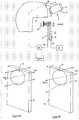
Figure 1 is a schematic view of a helmet-mounted display apparatus according to the invention, comprising a pair of night-vision goggles (NVG) attached to a helmet and positioned in a stowed position;Figure 2 is a schematic view of a helmet-mounted display apparatus according to the invention, comprising a pair of night-vision goggles (NVG) attached to a helmet and positioned in a deployed position to permit viewing of a scene therethrough by a user;Figure 3 schematically illustrates a slab waveguide display;Figures 4A and 4B show two switched states of a switchable holographic Bragg grating unit;Figure 5 shows a binocular night vision goggles (NVG) according to an embodiment the invention.- In the drawings, like articles are assigned like reference symbols.
- Referring to
Figure 1 , there is shown a helmet mounted display apparatus comprising an optical ocular part (1, 2, 3) which is one of two separate and parallel monocular components of a pair of binoculars of a night-vision goggle (NVG) unit. The NVGs are arranged for viewing a night-time scene therethrough and include an objective lens part (2) optically coupled to an eyepiece lens part (3) via an image intensifier part (1) arranged to intensify an image of a scene formed by the objective lens part for viewing via the eyepiece part. The NVGs may be such as would be readily available and/or apparent to the skilled person. - The display apparatus includes a planar waveguide display part (6) comprising an image generator part (7) for generating image-bearing light, and a planar waveguide upon or within which is formed two or more diffraction gratings (e.g. Bragg gratings). The image generator part is in communication with an image controller part (8) arranged to generate image data (digital or analogue) and to control the image generator part according to the image data to generate an image accordingly for display.
- A first such diffraction grating defines a waveguide input region for receiving image-bearing light from the image generator part (7) and for diffracting image-bearing light into the planar (e.g. slab) waveguide for guiding therealong to a transparent display output area thereof and thereat displaying the image. A second such diffraction grating located at the output area is arranged to diffract out of the waveguide the guided image-bearing light from the waveguide input region.
- The eyepiece part (3) and the waveguide display part are shown positioned (and are arranged to be moveably positioned) mutually in register for the viewing simultaneously an external night-time scene such that a display image from the image generator part is incorporated in the scene through the transparent display output area of the waveguide part (6).
- A switchable holographic lens part (9) is positioned in register with the display output area of the waveguide part (6) for focussing simultaneously the night-time scene produced by the NVG (1, 2, 3) and the incorporated image-bearing light for focussed viewing by a user. (13).
- The waveguide display part is arranged to output the image-bearing light at the display output area as collimated light. The eyepiece part (3) of the ocular part is arranged to be adjustable in optical power to enable a user to control the focus of the scene-bearing light output thereby. When used in isolation, a typical pair of NVGs would be arranged with an eyepiece of negative optical power set to diverge the scene-bearing light output thereby to achieve a close focus for use by a user/wearer of the NVGs. However, this conflicts with the collimating output power (e.g. substantially/effectively zero, or negligibly small optical power) of the planar waveguide which does not bring image-bearing light to a close focus. When the waveguide part and the NVG ocular part are used together, as shown in
Figure 2 , the state of focus of scene-bearing light and the state of focus of the image-bearing light is adjusted to render them consistent and optimal. This avoids the visual discomfort a user will otherwise suffer and permits the display apparatus to display both a night-time scene and the image conveyed by the waveguide part concurrently (the latter overlaid on the former) at the display output area of the waveguide part via collimated light conveying both the night-time scene and the guided image from the image generator part (7). - The switchable holographic lens comprises an electrically switchable transmissive Bragg grating formed on a transparent substrate. It is structured to define a holographic optical lens which has a negative optical power (e.g. -1.0 Dioptres) when activated electrically, and has effectively/substantially no optical power when not electrically activated (e.g. effectively zero Dioptres). When activated, the holographic lens is thereby arranged to diverge light received thereby from the display output area to bring it to a close focus desired by a user. The light so focussed is received by the holographic lens as collimated light conveying both the night-time scene from the NVGs and the image-bearing light originating from the image generator part (7).
- The focuser part may be switchable according to a switch control unit (10) between a first state shown in
Figure 1 in which it possesses substantially no optical power and a second state shown inFigure 2 in which it possesses an optical power for focussing light received thereby from the display output area. - The ocular part of the NVGs is moveably connected via a pivotable connection arm (4) to a helmet (5) to which the waveguide display part is connected or fixed. The ocular part is (e.g. pivotingly) moveable relative to the helmet between a first "stowed" position (
Figure 1 ) in which it is not in register with the waveguide display part and a second "deployed" position (Figure 2 ) in which it is so in register. - The control unit is arranged to control the focuser part to switch from the first state to the second state when the ocular part is moved from the stowed position into the deployed position, and similarly, to switch from the second state to the first state when the ocular part is moved from the deployed position into the stowed position. In this way, with the holographic lens part switched "off (i.e. no lens) the optical waveguide part is able to be used when the NVGs are in the stowed position and the user's eyes naturally focus to receive collimated image-bearing light from the waveguide part when viewing the environment through the display area of the waveguide part - e.g. during the daytime. Conversely, when it is desired to use the NVGs while still using the waveguide display part, the holographic lens is switched on and the eyepiece of the NVG ocular set to collimate its output. This enables the light output of both the ocular and the waveguide part to be suitably close-focussed by the holographic lens with optimal comfort for the user. In effect, the holographic lens serves the function which is usually served by the eyepiece of the NVG ocular, while allowing the image conveyed by the waveguide to be comfortably incorporated into the overall scene viewed by the user (13).
Figure 3 shows schematically an optical waveguide suitable for the waveguide display part (6). The optical waveguide is a slab waveguide comprising a first (input) diffractive grating region (14) arranged to receive image-bearing light from the image generator part (7) and to diffract the received light along the optical waveguide by total internal reflection between the planar surfaces of the slab waveguide. An intermediate diffraction grating (15) is optically coupled to the first diffractive grating region by the optical waveguide to receive the diffracted light from the first grating and to expand the received light in a lateral dimension by diffraction as shown by arrows (15A). A second (output) diffractive grating region (16) is optically coupled to the intermediate diffraction grating by the optical waveguide to receive the expanded light and to output the received expanded light from the optical waveguide by diffraction thereby to display the image conveyed by the image-bearing light when input at the first (input) diffraction grating (14).- The image projector part (7) may be a micro-display pico-projector, such as would be readily available to the skilled person. For example, the pico-projector may include an illumination source (if required), a micro-display area, and one of more lenses and optical components arranged to collimate an image from the micri-display area and inject it into the waveguide. For example, the micro-display may be a reflective LCoS (Liquid crystal on silicon) device, which is a micro-projection or micro-display technology well known in the art. Alternatively, the micro-display may be DMD (digital micro-mirror device) also well known in the art, which may comprise a chip having on its surface many microscopic mirrors arranged in an array which correspond to the pixels in an image to be displayed. The mirrors can be individually rotated to an on or off state to collectively generate an image to be displayed via reflected light.
Figures 4A and 4B schematically show the switchable holographic lens unit in an un-activated state ("off") in which no holographic lens is present (Fig. 4A ) and also in an activated state ("on") in which a holographic lens is generated. The unit comprises an electrically switchable transmissive Bragg grating (17) formed on a transparent substrate (9) of plastic or glass of other suitable optically transmissive material such as would be readily apparent to the skilled person. The switchable transmissive Bragg grating may comprise a Bragg grating recorded into liquid crystal such as is known in the art. An example of this is described in"Electro-optic properties of switchable gratings made of polymer and nematic liquid-crystal slices" by A. d'Alessandro et al.: June 15, 2004 / Vol. 29, No. 12 / OPTICS LETTERS. An alternative is to use a liquid crystal switchable lens such as is described inEP0693188B1 .- It is structured to define a holographic optical lens which has a negative optical power (e.g. - 1.0 Dioptres) when activated electrically by application of electrical voltage to cause the distribution of refractive index across the surface of the unit (9) to vary in such a way as to define the Bragg grating. Removal of the electrical voltage removes the pattern of refractive index and causes the Bragg grating to disappear.
- Thus, when no electrical voltage is applied the unit has effectively/substantially no optical power (e.g. effectively zero Dioptres). When activated, the holographic lens is thereby generated and is arranged to diverge light received thereby from the display output area (16) of the optical waveguide part (6) to bring it to a close focus desired by a user, as shown in
Figure 4B . - The switch control unit (10) is arranged to selectively apply/remove the required voltage to the switchable Bragg grating unit (9) to cause it to switch between the first state shown in
Figures 1 and 4A in which it possesses substantially no optical power and the second state shown inFigures 2 and4B in which it possesses negative optical power. The switch control unit (10) may, in preferred embodiments be connected to an external switch element (20) formed in the pivotable connection arm (or alternatively in the helmet 5) which is arranged to adopt automatically a first switch state when the NVGs are in the stowed position (Fig.1 ) and to adopt automatically a second state when the NVGs are in the deployed position (Fig.2 ). The switch control unit (10) is arranged, in such embodiments, to be responsive to the external switch element when in the first state to not activate the switchable Bragg grating, and to be responsive to the external switch element when in the second state to activate the switchable Bragg grating. In this way, the switchable Bragg grating may be automatically activated when the NVGs are deployed. In other embodiments, the external switch unit may be simply a hand-operated switch operable directly (manually) by the user. - The setting of the focus of an ocular of the NVGs may be performed manually by the wearer by adjustment of the eyepiece(s) thereof. An appropriate eyepiece may thus be manually adjusted to collimate by the wearer.
Figure 5 shows schematically how a pair of NVG oculars may be used with the waveguide display part and the focuser part of the invention in a preferred embodiment. Only one of the two oculars is arranged in combination with a waveguide display part (6) and focuser part (9). That ocular (13) is arranged to output collimated light from a viewed scene, whereas the other ocular (1B, 2B, 3B) of the pair is arranged to output divergent light close-focussed via eyepiece (3B) optical elements possessing negative optical power (e.g. about -1.0 Dioptres). The negative optical power of that other ocular (3B) is substantially matched by the negative optical poser of the focuser unit (9) with the result that the user sees a given scene through both eyes (13 and 13B) appropriately focussed with an image from an image generation unit (7) superimposed thereupon in the view through one eye (13).- As can be observed from
Figures 1 ,2 and5 , the planar waveguide display part (6) and the switchable holographic lens part (9) are arranged in the field of view of a user (13) such that the user (13) will view the scene and information generated by the image controller part (8) superimposed upon the view of the scene. Furthermore, the planar waveguide display part (6) and the switchable holographic lens part (9) are arrange such that the optical ocular part (1, 2, 3), which is one of two separate and parallel monocular components of a pair of binoculars of a night-vision goggle (NVG) unit, can be moved between stowed and deployed position such that the planar waveguide display part (6) and the switchable holographic lens part (9) are positioned between the eye of the user and the optical ocular part (1, 2, 3). This means that when the optical ocular part (1, 2, 3) is in the stowed position (Figure 1 ) the planar waveguide display part (6) can provide symbology or imagery to overlay the forward scene and when the optical ocular part (1, 2, 3) is moved to the deployed position (Figure 2 ) the planar waveguide display part (6) and the switchable holographic lens part (9) do not interfere with deployment whilst being able to provide symbology or imagery to overlay the enhanced night vision forward scene. Accordingly, this allows the image bearing light to be generated between the user's eye and an image intensifier of the ocular part (1, 2, 3). - The embodiments described above are intended as non-limited examples of the invention the scope of which is intended to encompass variants, modifications and equivalents to the examples such as would be readily apparent to the skilled person.
Claims (15)
- A display apparatus comprising:an optical ocular part (3) for viewing a scene therethrough; anda waveguide display part (6) arranged for guiding image-bearing light from an image generator part to a transparent display output area of the waveguide display part such that the image-bearing light is viewable combined with light from the scene passing through the transparent display output area,wherein at least one of the ocular part and the waveguide display part is moveable relative to the other between a stowed relative position and a relative position of alignment such that when in the relative position of alignment, light from the scene viewable through the ocular part is arranged to pass through the transparent display output area and to be viewable combined with the image-bearing light,the display apparatus further comprising a switchable focuser part (17) positioned in alignment with the display output area for focussing simultaneously light from the scene viewable through the ocular part, when the waveguide display part and the ocular part are in the relative position of alignment, combined with the image-bearing light for focussed viewing by a user,wherein the state of focus of the light from the scene after passing through the optical ocular part is consistent with the state of focus of the image-bearing light.
- The display apparatus according to claim 1, in which the image-bearing light is collimated and the ocular part is arranged or is adjustable to output to the display output area collimated light from the scene.
- The display apparatus according to claim 1 or claim 2, in which the focuser part is arranged or operable to possess a negative optical power thereby to diverge light received from the display output area.
- The display apparatus according to any one of the preceding claims, in which the focuser part is switchable between a first state in which it possesses substantially no optical power and a second state in which it possesses an optical power for focussing light received from the display output area.
- The display apparatus according to claim 4, in which the ocular part is moveably connected to the waveguide display part and is moveable between a first position in which it is in the stowed relative position with respect to the waveguide display part and a second position in which it is in the relative position of alignment with respect to the waveguide display part.
- The display apparatus according to claim 5, in which the focuser part is arranged to switch from said first state to said second state when the ocular part is moved from said first position into said second position.
- The display apparatus according to claim 5 or claim 6, in which the focuser part is arranged to switch from said second state to said first state when the ocular part is moved from said second position into said first position.
- The display apparatus according to any one of claims 5 to 7, further comprising a switch element arranged to detect a change in relative position of the ocular part and the waveguide display part from the first position to the second position and from the second position to the first position thereby to switch the focuser part from the first state to the second state and from the second state to the first state, respectively.
- The display apparatus according to any one of the preceding claims, in which the waveguide display part comprises a planar waveguide display.
- The display apparatus according to any one of the preceding claims, in which the ocular part is comprised within a monocular lens assembly.
- The display apparatus according to any one of claims 1 to 9, in which the ocular part is comprised within one lens assembly within a binocular lens assembly.
- The display apparatus according to claim 11, wherein each lens assembly of the binocular lens assembly includes an independently adjustable eyepiece lens such that the eyepiece lens of the assembly comprising the ocular part may be independently adjusted such that the state of focus of the light from the scene after passing through the ocular part is consistent with the state of focus of the image-bearing light.
- The display apparatus according to claim 12, wherein the eyepiece of the lens assembly comprising the ocular part is arranged to output collimated light from the scene and the eyepiece of the other lens assembly of the binocular lens assembly is arranged to output focused light from the scene, such that the optical power of the eyepiece of the other lens assembly is substantially matched by the optical power of the focuser part when switched to said second state.
- The display apparatus according to any one of the preceding claims, in which the ocular part is comprised in a lens assembly of a night vision goggle system.
- The display apparatus according to any one of the preceding claims, in which the switchable focuser part comprises a switchable transmissive Bragg grating.
Priority Applications (1)
| Application Number | Priority Date | Filing Date | Title |
|---|---|---|---|
| EP13799641.9AEP2929391B1 (en) | 2012-12-10 | 2013-11-27 | Improvements in and relating to displays |
Applications Claiming Priority (4)
| Application Number | Priority Date | Filing Date | Title |
|---|---|---|---|
| EP12275197.7AEP2741121A1 (en) | 2012-12-10 | 2012-12-10 | Improvements in or relating to displays |
| GB1222162.8AGB2508662B (en) | 2012-12-10 | 2012-12-10 | Improvements in and relating to displays |
| EP13799641.9AEP2929391B1 (en) | 2012-12-10 | 2013-11-27 | Improvements in and relating to displays |
| PCT/GB2013/053136WO2014091201A1 (en) | 2012-12-10 | 2013-11-27 | Improvements in and relating to displays |
Publications (2)
| Publication Number | Publication Date |
|---|---|
| EP2929391A1 EP2929391A1 (en) | 2015-10-14 |
| EP2929391B1true EP2929391B1 (en) | 2020-04-15 |
Family
ID=49713394
Family Applications (1)
| Application Number | Title | Priority Date | Filing Date |
|---|---|---|---|
| EP13799641.9AActiveEP2929391B1 (en) | 2012-12-10 | 2013-11-27 | Improvements in and relating to displays |
Country Status (4)
| Country | Link |
|---|---|
| US (1) | US9684170B2 (en) |
| EP (1) | EP2929391B1 (en) |
| ES (1) | ES2788756T3 (en) |
| WO (1) | WO2014091201A1 (en) |
Families Citing this family (59)
| Publication number | Priority date | Publication date | Assignee | Title |
|---|---|---|---|---|
| GB0718706D0 (en) | 2007-09-25 | 2007-11-07 | Creative Physics Ltd | Method and apparatus for reducing laser speckle |
| US9335604B2 (en) | 2013-12-11 | 2016-05-10 | Milan Momcilo Popovich | Holographic waveguide display |
| US11726332B2 (en) | 2009-04-27 | 2023-08-15 | Digilens Inc. | Diffractive projection apparatus |
| US8233204B1 (en) | 2009-09-30 | 2012-07-31 | Rockwell Collins, Inc. | Optical displays |
| US11300795B1 (en) | 2009-09-30 | 2022-04-12 | Digilens Inc. | Systems for and methods of using fold gratings coordinated with output couplers for dual axis expansion |
| US11320571B2 (en) | 2012-11-16 | 2022-05-03 | Rockwell Collins, Inc. | Transparent waveguide display providing upper and lower fields of view with uniform light extraction |
| US10795160B1 (en) | 2014-09-25 | 2020-10-06 | Rockwell Collins, Inc. | Systems for and methods of using fold gratings for dual axis expansion |
| WO2012136970A1 (en) | 2011-04-07 | 2012-10-11 | Milan Momcilo Popovich | Laser despeckler based on angular diversity |
| WO2016020630A2 (en) | 2014-08-08 | 2016-02-11 | Milan Momcilo Popovich | Waveguide laser illuminator incorporating a despeckler |
| EP2995986B1 (en) | 2011-08-24 | 2017-04-12 | Rockwell Collins, Inc. | Data display |
| US10670876B2 (en) | 2011-08-24 | 2020-06-02 | Digilens Inc. | Waveguide laser illuminator incorporating a despeckler |
| US9366864B1 (en) | 2011-09-30 | 2016-06-14 | Rockwell Collins, Inc. | System for and method of displaying information without need for a combiner alignment detector |
| US9715067B1 (en) | 2011-09-30 | 2017-07-25 | Rockwell Collins, Inc. | Ultra-compact HUD utilizing waveguide pupil expander with surface relief gratings in high refractive index materials |
| US20150010265A1 (en) | 2012-01-06 | 2015-01-08 | Milan, Momcilo POPOVICH | Contact image sensor using switchable bragg gratings |
| CN106125308B (en) | 2012-04-25 | 2019-10-25 | 罗克韦尔柯林斯公司 | Device and method for displaying images |
| US9933684B2 (en) | 2012-11-16 | 2018-04-03 | Rockwell Collins, Inc. | Transparent waveguide display providing upper and lower fields of view having a specific light output aperture configuration |
| EP2929391B1 (en) | 2012-12-10 | 2020-04-15 | BAE SYSTEMS plc | Improvements in and relating to displays |
| WO2015015138A1 (en) | 2013-07-31 | 2015-02-05 | Milan Momcilo Popovich | Method and apparatus for contact image sensing |
| US10732407B1 (en) | 2014-01-10 | 2020-08-04 | Rockwell Collins, Inc. | Near eye head up display system and method with fixed combiner |
| US9244280B1 (en) | 2014-03-25 | 2016-01-26 | Rockwell Collins, Inc. | Near eye display system and method for display enhancement or redundancy |
| US10359736B2 (en) | 2014-08-08 | 2019-07-23 | Digilens Inc. | Method for holographic mastering and replication |
| WO2016042283A1 (en) | 2014-09-19 | 2016-03-24 | Milan Momcilo Popovich | Method and apparatus for generating input images for holographic waveguide displays |
| US9715110B1 (en)* | 2014-09-25 | 2017-07-25 | Rockwell Collins, Inc. | Automotive head up display (HUD) |
| US10088675B1 (en) | 2015-05-18 | 2018-10-02 | Rockwell Collins, Inc. | Turning light pipe for a pupil expansion system and method |
| WO2016113534A1 (en) | 2015-01-12 | 2016-07-21 | Milan Momcilo Popovich | Environmentally isolated waveguide display |
| US9632226B2 (en) | 2015-02-12 | 2017-04-25 | Digilens Inc. | Waveguide grating device |
| US11366316B2 (en) | 2015-05-18 | 2022-06-21 | Rockwell Collins, Inc. | Head up display (HUD) using a light pipe |
| US10247943B1 (en) | 2015-05-18 | 2019-04-02 | Rockwell Collins, Inc. | Head up display (HUD) using a light pipe |
| US10126552B2 (en) | 2015-05-18 | 2018-11-13 | Rockwell Collins, Inc. | Micro collimator system and method for a head up display (HUD) |
| US10108010B2 (en) | 2015-06-29 | 2018-10-23 | Rockwell Collins, Inc. | System for and method of integrating head up displays and head down displays |
| US10852541B2 (en) | 2015-07-03 | 2020-12-01 | Essilor International | Methods and systems for augmented reality |
| CN113759555B (en) | 2015-10-05 | 2024-09-20 | 迪吉伦斯公司 | Waveguide Display |
| US10598932B1 (en) | 2016-01-06 | 2020-03-24 | Rockwell Collins, Inc. | Head up display for integrating views of conformally mapped symbols and a fixed image source |
| CN108780224B (en) | 2016-03-24 | 2021-08-03 | 迪吉伦斯公司 | Method and apparatus for providing a polarization selective holographic waveguide device |
| US10890707B2 (en) | 2016-04-11 | 2021-01-12 | Digilens Inc. | Holographic waveguide apparatus for structured light projection |
| WO2018102834A2 (en) | 2016-12-02 | 2018-06-07 | Digilens, Inc. | Waveguide device with uniform output illumination |
| US10545346B2 (en) | 2017-01-05 | 2020-01-28 | Digilens Inc. | Wearable heads up displays |
| US10295824B2 (en) | 2017-01-26 | 2019-05-21 | Rockwell Collins, Inc. | Head up display with an angled light pipe |
| WO2018148730A1 (en)* | 2017-02-13 | 2018-08-16 | Aqueti Incorporated | Co-boresighted monocentric multiscale (mms) camera exhibiting galilean multiscale design |
| WO2019079350A2 (en) | 2017-10-16 | 2019-04-25 | Digilens, Inc. | Systems and methods for multiplying the image resolution of a pixelated display |
| CN108132534B (en)* | 2017-12-29 | 2020-09-04 | 西安睿维申电子科技有限公司 | Near-to-eye display system based on goggles form |
| EP3710876A4 (en) | 2018-01-08 | 2022-02-09 | DigiLens Inc. | SYSTEMS AND METHODS OF FABRICATING WAVEGUIDE CELLS |
| EP3710894B1 (en) | 2018-01-08 | 2025-07-30 | Digilens Inc. | Methods for fabricating optical waveguides |
| WO2019136476A1 (en) | 2018-01-08 | 2019-07-11 | Digilens, Inc. | Waveguide architectures and related methods of manufacturing |
| US10732569B2 (en) | 2018-01-08 | 2020-08-04 | Digilens Inc. | Systems and methods for high-throughput recording of holographic gratings in waveguide cells |
| EP3564730A1 (en)* | 2018-05-03 | 2019-11-06 | Qioptiq Limited | Digital image overlay in image intensified and day sight system |
| WO2020023779A1 (en) | 2018-07-25 | 2020-01-30 | Digilens Inc. | Systems and methods for fabricating a multilayer optical structure |
| US20200225471A1 (en) | 2019-01-14 | 2020-07-16 | Digilens Inc. | Holographic Waveguide Display with Light Control Layer |
| US20200247017A1 (en) | 2019-02-05 | 2020-08-06 | Digilens Inc. | Methods for Compensating for Optical Surface Nonuniformity |
| US20220283377A1 (en) | 2019-02-15 | 2022-09-08 | Digilens Inc. | Wide Angle Waveguide Display |
| KR102866596B1 (en) | 2019-02-15 | 2025-09-29 | 디지렌즈 인코포레이티드. | Method and device for providing a holographic waveguide display using an integral grating |
| WO2020186113A1 (en) | 2019-03-12 | 2020-09-17 | Digilens Inc. | Holographic waveguide backlight and related methods of manufacturing |
| EP3980825A4 (en) | 2019-06-07 | 2023-05-03 | Digilens Inc. | WAVEGUIDES WITH TRANSMITTING AND REFLECTING GRIDS AND RELATED MANUFACTURING PROCESSES |
| EP4004646A4 (en) | 2019-07-29 | 2023-09-06 | Digilens Inc. | METHODS AND APPARATUS FOR MULTIPLYING THE IMAGE RESOLUTION AND FIELD OF VIEW OF A PIXELATED DISPLAY SCREEN |
| US11402640B1 (en) | 2019-08-15 | 2022-08-02 | Apple Inc. | Display adjustment for head-mountable device |
| KR102775783B1 (en) | 2019-08-29 | 2025-02-28 | 디지렌즈 인코포레이티드. | Vacuum grid and method for manufacturing the same |
| WO2021191584A1 (en)* | 2020-03-24 | 2021-09-30 | Bae Systems Plc | Optical system |
| WO2022150841A1 (en) | 2021-01-07 | 2022-07-14 | Digilens Inc. | Grating structures for color waveguides |
| US12158612B2 (en) | 2021-03-05 | 2024-12-03 | Digilens Inc. | Evacuated periodic structures and methods of manufacturing |
Family Cites Families (10)
| Publication number | Priority date | Publication date | Assignee | Title |
|---|---|---|---|---|
| EP1808722A3 (en)* | 1996-10-08 | 2007-07-25 | The Microoptical Corporation | Image Combining System for Eyeglasses and Face Masks |
| FR2903786B1 (en) | 2006-07-11 | 2008-09-05 | Thales Sa | HELMET VISUALIZATION SYSTEM WITH INTERCHANGEABLE OPTICAL MODULES |
| WO2010070344A1 (en) | 2008-12-19 | 2010-06-24 | Bae Systems Plc | Display system |
| US8885112B2 (en) | 2009-10-27 | 2014-11-11 | Sbg Labs, Inc. | Compact holographic edge illuminated eyeglass display |
| US9223134B2 (en)* | 2010-02-28 | 2015-12-29 | Microsoft Technology Licensing, Llc | Optical imperfections in a light transmissive illumination system for see-through near-eye display glasses |
| US8467133B2 (en)* | 2010-02-28 | 2013-06-18 | Osterhout Group, Inc. | See-through display with an optical assembly including a wedge-shaped illumination system |
| US9341843B2 (en)* | 2010-02-28 | 2016-05-17 | Microsoft Technology Licensing, Llc | See-through near-eye display glasses with a small scale image source |
| US20150309316A1 (en)* | 2011-04-06 | 2015-10-29 | Microsoft Technology Licensing, Llc | Ar glasses with predictive control of external device based on event input |
| US9106909B2 (en) | 2010-04-20 | 2015-08-11 | Hewlett-Packard Development Company, L.P. | Stereo vision viewing systems |
| EP2929391B1 (en) | 2012-12-10 | 2020-04-15 | BAE SYSTEMS plc | Improvements in and relating to displays |
- 2013
- 2013-11-27EPEP13799641.9Apatent/EP2929391B1/enactiveActive
- 2013-11-27USUS14/650,686patent/US9684170B2/enactiveActive
- 2013-11-27WOPCT/GB2013/053136patent/WO2014091201A1/enactiveApplication Filing
- 2013-11-27ESES13799641Tpatent/ES2788756T3/enactiveActive
Non-Patent Citations (1)
| Title |
|---|
| None* |
Also Published As
| Publication number | Publication date |
|---|---|
| WO2014091201A1 (en) | 2014-06-19 |
| EP2929391A1 (en) | 2015-10-14 |
| US9684170B2 (en) | 2017-06-20 |
| ES2788756T3 (en) | 2020-10-22 |
| US20150316768A1 (en) | 2015-11-05 |
Similar Documents
| Publication | Publication Date | Title |
|---|---|---|
| EP2929391B1 (en) | Improvements in and relating to displays | |
| US10663728B2 (en) | Relating to displays | |
| US8079713B2 (en) | Near eye display system | |
| EP3889670B1 (en) | Optical system for a display with an off axis projector | |
| CN108957752B (en) | Head-mounted display | |
| JP4411547B2 (en) | Image display device | |
| JP4155343B2 (en) | An optical system for guiding light from two scenes to the viewer's eye alternatively or simultaneously | |
| AU2015341881B2 (en) | Head-borne viewing system comprising crossed optics | |
| KR102833128B1 (en) | Optical system with cylindrical waveguide | |
| KR20030088217A (en) | Wearable display system enabling adjustment of magnfication | |
| JP2018514803A (en) | Free-form nanostructured surfaces for virtual and augmented reality near-eye displays | |
| US10732407B1 (en) | Near eye head up display system and method with fixed combiner | |
| JP2022509114A (en) | Near focus correction AR glasses | |
| EP3091740A1 (en) | Improvements in and relating to displays | |
| EP3230789A1 (en) | Display system | |
| US10459228B1 (en) | Head wearable display using powerless optical combiner | |
| JP2004145367A (en) | Image displaying device | |
| CN115552295A (en) | Eyebox Steering and Field of View Extension Using Beam Steering Elements | |
| EP2741121A1 (en) | Improvements in or relating to displays | |
| GB2508662A (en) | Improved display |
Legal Events
| Date | Code | Title | Description |
|---|---|---|---|
| PUAI | Public reference made under article 153(3) epc to a published international application that has entered the european phase | Free format text:ORIGINAL CODE: 0009012 | |
| 17P | Request for examination filed | Effective date:20150616 | |
| AK | Designated contracting states | Kind code of ref document:A1 Designated state(s):AL AT BE BG CH CY CZ DE DK EE ES FI FR GB GR HR HU IE IS IT LI LT LU LV MC MK MT NL NO PL PT RO RS SE SI SK SM TR | |
| AX | Request for extension of the european patent | Extension state:BA ME | |
| DAX | Request for extension of the european patent (deleted) | ||
| GRAP | Despatch of communication of intention to grant a patent | Free format text:ORIGINAL CODE: EPIDOSNIGR1 | |
| STAA | Information on the status of an ep patent application or granted ep patent | Free format text:STATUS: GRANT OF PATENT IS INTENDED | |
| INTG | Intention to grant announced | Effective date:20191108 | |
| GRAS | Grant fee paid | Free format text:ORIGINAL CODE: EPIDOSNIGR3 | |
| GRAA | (expected) grant | Free format text:ORIGINAL CODE: 0009210 | |
| STAA | Information on the status of an ep patent application or granted ep patent | Free format text:STATUS: THE PATENT HAS BEEN GRANTED | |
| AK | Designated contracting states | Kind code of ref document:B1 Designated state(s):AL AT BE BG CH CY CZ DE DK EE ES FI FR GB GR HR HU IE IS IT LI LT LU LV MC MK MT NL NO PL PT RO RS SE SI SK SM TR | |
| REG | Reference to a national code | Ref country code:CH Ref legal event code:EP | |
| REG | Reference to a national code | Ref country code:DE Ref legal event code:R096 Ref document number:602013067992 Country of ref document:DE | |
| REG | Reference to a national code | Ref country code:IE Ref legal event code:FG4D | |
| REG | Reference to a national code | Ref country code:AT Ref legal event code:REF Ref document number:1258000 Country of ref document:AT Kind code of ref document:T Effective date:20200515 | |
| REG | Reference to a national code | Ref country code:NL Ref legal event code:MP Effective date:20200415 | |
| REG | Reference to a national code | Ref country code:LT Ref legal event code:MG4D | |
| REG | Reference to a national code | Ref country code:ES Ref legal event code:FG2A Ref document number:2788756 Country of ref document:ES Kind code of ref document:T3 Effective date:20201022 | |
| PG25 | Lapsed in a contracting state [announced via postgrant information from national office to epo] | Ref country code:PT Free format text:LAPSE BECAUSE OF FAILURE TO SUBMIT A TRANSLATION OF THE DESCRIPTION OR TO PAY THE FEE WITHIN THE PRESCRIBED TIME-LIMIT Effective date:20200817 Ref country code:NL Free format text:LAPSE BECAUSE OF FAILURE TO SUBMIT A TRANSLATION OF THE DESCRIPTION OR TO PAY THE FEE WITHIN THE PRESCRIBED TIME-LIMIT Effective date:20200415 Ref country code:IS Free format text:LAPSE BECAUSE OF FAILURE TO SUBMIT A TRANSLATION OF THE DESCRIPTION OR TO PAY THE FEE WITHIN THE PRESCRIBED TIME-LIMIT Effective date:20200815 Ref country code:SE Free format text:LAPSE BECAUSE OF FAILURE TO SUBMIT A TRANSLATION OF THE DESCRIPTION OR TO PAY THE FEE WITHIN THE PRESCRIBED TIME-LIMIT Effective date:20200415 Ref country code:GR Free format text:LAPSE BECAUSE OF FAILURE TO SUBMIT A TRANSLATION OF THE DESCRIPTION OR TO PAY THE FEE WITHIN THE PRESCRIBED TIME-LIMIT Effective date:20200716 Ref country code:NO Free format text:LAPSE BECAUSE OF FAILURE TO SUBMIT A TRANSLATION OF THE DESCRIPTION OR TO PAY THE FEE WITHIN THE PRESCRIBED TIME-LIMIT Effective date:20200715 Ref country code:FI Free format text:LAPSE BECAUSE OF FAILURE TO SUBMIT A TRANSLATION OF THE DESCRIPTION OR TO PAY THE FEE WITHIN THE PRESCRIBED TIME-LIMIT Effective date:20200415 Ref country code:LT Free format text:LAPSE BECAUSE OF FAILURE TO SUBMIT A TRANSLATION OF THE DESCRIPTION OR TO PAY THE FEE WITHIN THE PRESCRIBED TIME-LIMIT Effective date:20200415 | |
| REG | Reference to a national code | Ref country code:AT Ref legal event code:MK05 Ref document number:1258000 Country of ref document:AT Kind code of ref document:T Effective date:20200415 | |
| PG25 | Lapsed in a contracting state [announced via postgrant information from national office to epo] | Ref country code:BG Free format text:LAPSE BECAUSE OF FAILURE TO SUBMIT A TRANSLATION OF THE DESCRIPTION OR TO PAY THE FEE WITHIN THE PRESCRIBED TIME-LIMIT Effective date:20200715 Ref country code:HR Free format text:LAPSE BECAUSE OF FAILURE TO SUBMIT A TRANSLATION OF THE DESCRIPTION OR TO PAY THE FEE WITHIN THE PRESCRIBED TIME-LIMIT Effective date:20200415 Ref country code:RS Free format text:LAPSE BECAUSE OF FAILURE TO SUBMIT A TRANSLATION OF THE DESCRIPTION OR TO PAY THE FEE WITHIN THE PRESCRIBED TIME-LIMIT Effective date:20200415 Ref country code:LV Free format text:LAPSE BECAUSE OF FAILURE TO SUBMIT A TRANSLATION OF THE DESCRIPTION OR TO PAY THE FEE WITHIN THE PRESCRIBED TIME-LIMIT Effective date:20200415 | |
| PG25 | Lapsed in a contracting state [announced via postgrant information from national office to epo] | Ref country code:AL Free format text:LAPSE BECAUSE OF FAILURE TO SUBMIT A TRANSLATION OF THE DESCRIPTION OR TO PAY THE FEE WITHIN THE PRESCRIBED TIME-LIMIT Effective date:20200415 | |
| REG | Reference to a national code | Ref country code:DE Ref legal event code:R097 Ref document number:602013067992 Country of ref document:DE | |
| PG25 | Lapsed in a contracting state [announced via postgrant information from national office to epo] | Ref country code:CZ Free format text:LAPSE BECAUSE OF FAILURE TO SUBMIT A TRANSLATION OF THE DESCRIPTION OR TO PAY THE FEE WITHIN THE PRESCRIBED TIME-LIMIT Effective date:20200415 Ref country code:RO Free format text:LAPSE BECAUSE OF FAILURE TO SUBMIT A TRANSLATION OF THE DESCRIPTION OR TO PAY THE FEE WITHIN THE PRESCRIBED TIME-LIMIT Effective date:20200415 Ref country code:EE Free format text:LAPSE BECAUSE OF FAILURE TO SUBMIT A TRANSLATION OF THE DESCRIPTION OR TO PAY THE FEE WITHIN THE PRESCRIBED TIME-LIMIT Effective date:20200415 Ref country code:AT Free format text:LAPSE BECAUSE OF FAILURE TO SUBMIT A TRANSLATION OF THE DESCRIPTION OR TO PAY THE FEE WITHIN THE PRESCRIBED TIME-LIMIT Effective date:20200415 Ref country code:SM Free format text:LAPSE BECAUSE OF FAILURE TO SUBMIT A TRANSLATION OF THE DESCRIPTION OR TO PAY THE FEE WITHIN THE PRESCRIBED TIME-LIMIT Effective date:20200415 Ref country code:DK Free format text:LAPSE BECAUSE OF FAILURE TO SUBMIT A TRANSLATION OF THE DESCRIPTION OR TO PAY THE FEE WITHIN THE PRESCRIBED TIME-LIMIT Effective date:20200415 | |
| PLBE | No opposition filed within time limit | Free format text:ORIGINAL CODE: 0009261 | |
| STAA | Information on the status of an ep patent application or granted ep patent | Free format text:STATUS: NO OPPOSITION FILED WITHIN TIME LIMIT | |
| PG25 | Lapsed in a contracting state [announced via postgrant information from national office to epo] | Ref country code:PL Free format text:LAPSE BECAUSE OF FAILURE TO SUBMIT A TRANSLATION OF THE DESCRIPTION OR TO PAY THE FEE WITHIN THE PRESCRIBED TIME-LIMIT Effective date:20200415 Ref country code:SK Free format text:LAPSE BECAUSE OF FAILURE TO SUBMIT A TRANSLATION OF THE DESCRIPTION OR TO PAY THE FEE WITHIN THE PRESCRIBED TIME-LIMIT Effective date:20200415 | |
| 26N | No opposition filed | Effective date:20210118 | |
| PG25 | Lapsed in a contracting state [announced via postgrant information from national office to epo] | Ref country code:SI Free format text:LAPSE BECAUSE OF FAILURE TO SUBMIT A TRANSLATION OF THE DESCRIPTION OR TO PAY THE FEE WITHIN THE PRESCRIBED TIME-LIMIT Effective date:20200415 | |
| PG25 | Lapsed in a contracting state [announced via postgrant information from national office to epo] | Ref country code:MC Free format text:LAPSE BECAUSE OF FAILURE TO SUBMIT A TRANSLATION OF THE DESCRIPTION OR TO PAY THE FEE WITHIN THE PRESCRIBED TIME-LIMIT Effective date:20200415 | |
| REG | Reference to a national code | Ref country code:CH Ref legal event code:PL | |
| PG25 | Lapsed in a contracting state [announced via postgrant information from national office to epo] | Ref country code:LU Free format text:LAPSE BECAUSE OF NON-PAYMENT OF DUE FEES Effective date:20201127 | |
| REG | Reference to a national code | Ref country code:BE Ref legal event code:MM Effective date:20201130 | |
| PG25 | Lapsed in a contracting state [announced via postgrant information from national office to epo] | Ref country code:CH Free format text:LAPSE BECAUSE OF NON-PAYMENT OF DUE FEES Effective date:20201130 Ref country code:LI Free format text:LAPSE BECAUSE OF NON-PAYMENT OF DUE FEES Effective date:20201130 | |
| PG25 | Lapsed in a contracting state [announced via postgrant information from national office to epo] | Ref country code:IE Free format text:LAPSE BECAUSE OF NON-PAYMENT OF DUE FEES Effective date:20201127 | |
| PG25 | Lapsed in a contracting state [announced via postgrant information from national office to epo] | Ref country code:MT Free format text:LAPSE BECAUSE OF FAILURE TO SUBMIT A TRANSLATION OF THE DESCRIPTION OR TO PAY THE FEE WITHIN THE PRESCRIBED TIME-LIMIT Effective date:20200415 Ref country code:CY Free format text:LAPSE BECAUSE OF FAILURE TO SUBMIT A TRANSLATION OF THE DESCRIPTION OR TO PAY THE FEE WITHIN THE PRESCRIBED TIME-LIMIT Effective date:20200415 | |
| PG25 | Lapsed in a contracting state [announced via postgrant information from national office to epo] | Ref country code:MK Free format text:LAPSE BECAUSE OF FAILURE TO SUBMIT A TRANSLATION OF THE DESCRIPTION OR TO PAY THE FEE WITHIN THE PRESCRIBED TIME-LIMIT Effective date:20200415 | |
| PG25 | Lapsed in a contracting state [announced via postgrant information from national office to epo] | Ref country code:BE Free format text:LAPSE BECAUSE OF NON-PAYMENT OF DUE FEES Effective date:20201130 | |
| PGFP | Annual fee paid to national office [announced via postgrant information from national office to epo] | Ref country code:DE Payment date:20241022 Year of fee payment:12 | |
| PGFP | Annual fee paid to national office [announced via postgrant information from national office to epo] | Ref country code:GB Payment date:20241023 Year of fee payment:12 | |
| PGFP | Annual fee paid to national office [announced via postgrant information from national office to epo] | Ref country code:FR Payment date:20241022 Year of fee payment:12 | |
| PGFP | Annual fee paid to national office [announced via postgrant information from national office to epo] | Ref country code:IT Payment date:20241022 Year of fee payment:12 Ref country code:ES Payment date:20241202 Year of fee payment:12 | |
| PGFP | Annual fee paid to national office [announced via postgrant information from national office to epo] | Ref country code:TR Payment date:20241101 Year of fee payment:12 |