EP2928515B1 - Adaptable wound drainage system - Google Patents
Adaptable wound drainage systemDownload PDFInfo
- Publication number
- EP2928515B1 EP2928515B1EP13812222.1AEP13812222AEP2928515B1EP 2928515 B1EP2928515 B1EP 2928515B1EP 13812222 AEP13812222 AEP 13812222AEP 2928515 B1EP2928515 B1EP 2928515B1
- Authority
- EP
- European Patent Office
- Prior art keywords
- elongate
- drainage
- elongate members
- manifold
- elongate member
- Prior art date
- Legal status (The legal status is an assumption and is not a legal conclusion. Google has not performed a legal analysis and makes no representation as to the accuracy of the status listed.)
- Active
Links
- 239000012530fluidSubstances0.000claimsdescription89
- 238000004891communicationMethods0.000claimsdescription47
- 230000013011matingEffects0.000claimsdescription20
- 210000001519tissueAnatomy0.000description62
- 206010052428WoundDiseases0.000description11
- 208000027418Wounds and injuryDiseases0.000description11
- 238000000926separation methodMethods0.000description7
- 230000008878couplingEffects0.000description6
- 238000010168coupling processMethods0.000description6
- 238000005859coupling reactionMethods0.000description6
- 239000000463materialSubstances0.000description6
- 238000000034methodMethods0.000description6
- 210000002615epidermisAnatomy0.000description5
- 230000002452interceptive effectEffects0.000description5
- RTAQQCXQSZGOHL-UHFFFAOYSA-NTitaniumChemical compound[Ti]RTAQQCXQSZGOHL-UHFFFAOYSA-N0.000description4
- 238000001514detection methodMethods0.000description4
- 230000000295complement effectEffects0.000description3
- 238000012806monitoring deviceMethods0.000description3
- 238000007789sealingMethods0.000description3
- 206010018852HaematomaDiseases0.000description2
- 206010040102SeromaDiseases0.000description2
- 239000000853adhesiveSubstances0.000description2
- 230000001070adhesive effectEffects0.000description2
- 210000004207dermisAnatomy0.000description2
- 208000015181infectious diseaseDiseases0.000description2
- 238000012544monitoring processMethods0.000description2
- 206010033675panniculitisDiseases0.000description2
- -1polyethylenePolymers0.000description2
- 229920002635polyurethanePolymers0.000description2
- 239000004814polyurethaneSubstances0.000description2
- 239000004800polyvinyl chlorideSubstances0.000description2
- 210000004304subcutaneous tissueAnatomy0.000description2
- 239000000126substanceSubstances0.000description2
- 230000007704transitionEffects0.000description2
- 238000009966trimmingMethods0.000description2
- 206010003445AscitesDiseases0.000description1
- 241000894006BacteriaSpecies0.000description1
- 239000004698PolyethyleneSubstances0.000description1
- 239000004743PolypropyleneSubstances0.000description1
- NIXOWILDQLNWCW-UHFFFAOYSA-Nacrylic acid groupChemical groupC(C=C)(=O)ONIXOWILDQLNWCW-UHFFFAOYSA-N0.000description1
- 210000000577adipose tissueAnatomy0.000description1
- 230000004075alterationEffects0.000description1
- 239000008280bloodSubstances0.000description1
- 210000004369bloodAnatomy0.000description1
- 210000000988bone and boneAnatomy0.000description1
- 210000000845cartilageAnatomy0.000description1
- 238000012412chemical couplingMethods0.000description1
- 238000000576coating methodMethods0.000description1
- 210000002808connective tissueAnatomy0.000description1
- 239000002537cosmeticSubstances0.000description1
- 230000002500effect on skinEffects0.000description1
- HQQADJVZYDDRJT-UHFFFAOYSA-Nethene;prop-1-eneChemical groupC=C.CC=CHQQADJVZYDDRJT-UHFFFAOYSA-N0.000description1
- 210000000416exudates and transudateAnatomy0.000description1
- 230000002706hydrostatic effectEffects0.000description1
- 208000014674injuryDiseases0.000description1
- 238000003780insertionMethods0.000description1
- 230000037431insertionEffects0.000description1
- 210000003041ligamentAnatomy0.000description1
- 239000007788liquidSubstances0.000description1
- 210000003205muscleAnatomy0.000description1
- 229920000573polyethylenePolymers0.000description1
- 229920000642polymerPolymers0.000description1
- 229920001155polypropylenePolymers0.000description1
- 229920001296polysiloxanePolymers0.000description1
- 229920000915polyvinyl chloridePolymers0.000description1
- 238000011176poolingMethods0.000description1
- 230000009467reductionEffects0.000description1
- 229920002379silicone rubberPolymers0.000description1
- 238000006467substitution reactionMethods0.000description1
- 239000003356suture materialSubstances0.000description1
- 210000002435tendonAnatomy0.000description1
- 230000001225therapeutic effectEffects0.000description1
- 230000008733traumaEffects0.000description1
- 230000002792vascularEffects0.000description1
Images


Classifications
- A—HUMAN NECESSITIES
- A61—MEDICAL OR VETERINARY SCIENCE; HYGIENE
- A61M—DEVICES FOR INTRODUCING MEDIA INTO, OR ONTO, THE BODY; DEVICES FOR TRANSDUCING BODY MEDIA OR FOR TAKING MEDIA FROM THE BODY; DEVICES FOR PRODUCING OR ENDING SLEEP OR STUPOR
- A61M1/00—Suction or pumping devices for medical purposes; Devices for carrying-off, for treatment of, or for carrying-over, body-liquids; Drainage systems
- A61M1/71—Suction drainage systems
- A—HUMAN NECESSITIES
- A61—MEDICAL OR VETERINARY SCIENCE; HYGIENE
- A61F—FILTERS IMPLANTABLE INTO BLOOD VESSELS; PROSTHESES; DEVICES PROVIDING PATENCY TO, OR PREVENTING COLLAPSING OF, TUBULAR STRUCTURES OF THE BODY, e.g. STENTS; ORTHOPAEDIC, NURSING OR CONTRACEPTIVE DEVICES; FOMENTATION; TREATMENT OR PROTECTION OF EYES OR EARS; BANDAGES, DRESSINGS OR ABSORBENT PADS; FIRST-AID KITS
- A61F13/00—Bandages or dressings; Absorbent pads
- A61F13/05—Bandages or dressings; Absorbent pads specially adapted for use with sub-pressure or over-pressure therapy, wound drainage or wound irrigation, e.g. for use with negative-pressure wound therapy [NPWT]
- A—HUMAN NECESSITIES
- A61—MEDICAL OR VETERINARY SCIENCE; HYGIENE
- A61M—DEVICES FOR INTRODUCING MEDIA INTO, OR ONTO, THE BODY; DEVICES FOR TRANSDUCING BODY MEDIA OR FOR TAKING MEDIA FROM THE BODY; DEVICES FOR PRODUCING OR ENDING SLEEP OR STUPOR
- A61M1/00—Suction or pumping devices for medical purposes; Devices for carrying-off, for treatment of, or for carrying-over, body-liquids; Drainage systems
- A61M1/71—Suction drainage systems
- A61M1/76—Handpieces
- A—HUMAN NECESSITIES
- A61—MEDICAL OR VETERINARY SCIENCE; HYGIENE
- A61M—DEVICES FOR INTRODUCING MEDIA INTO, OR ONTO, THE BODY; DEVICES FOR TRANSDUCING BODY MEDIA OR FOR TAKING MEDIA FROM THE BODY; DEVICES FOR PRODUCING OR ENDING SLEEP OR STUPOR
- A61M1/00—Suction or pumping devices for medical purposes; Devices for carrying-off, for treatment of, or for carrying-over, body-liquids; Drainage systems
- A61M1/90—Negative pressure wound therapy devices, i.e. devices for applying suction to a wound to promote healing, e.g. including a vacuum dressing
- A61M1/91—Suction aspects of the dressing
- A61M1/916—Suction aspects of the dressing specially adapted for deep wounds
- A—HUMAN NECESSITIES
- A61—MEDICAL OR VETERINARY SCIENCE; HYGIENE
- A61M—DEVICES FOR INTRODUCING MEDIA INTO, OR ONTO, THE BODY; DEVICES FOR TRANSDUCING BODY MEDIA OR FOR TAKING MEDIA FROM THE BODY; DEVICES FOR PRODUCING OR ENDING SLEEP OR STUPOR
- A61M1/00—Suction or pumping devices for medical purposes; Devices for carrying-off, for treatment of, or for carrying-over, body-liquids; Drainage systems
- A61M1/90—Negative pressure wound therapy devices, i.e. devices for applying suction to a wound to promote healing, e.g. including a vacuum dressing
- A61M1/91—Suction aspects of the dressing
- A61M1/918—Suction aspects of the dressing for multiple suction locations
- A—HUMAN NECESSITIES
- A61—MEDICAL OR VETERINARY SCIENCE; HYGIENE
- A61M—DEVICES FOR INTRODUCING MEDIA INTO, OR ONTO, THE BODY; DEVICES FOR TRANSDUCING BODY MEDIA OR FOR TAKING MEDIA FROM THE BODY; DEVICES FOR PRODUCING OR ENDING SLEEP OR STUPOR
- A61M1/00—Suction or pumping devices for medical purposes; Devices for carrying-off, for treatment of, or for carrying-over, body-liquids; Drainage systems
- A61M1/90—Negative pressure wound therapy devices, i.e. devices for applying suction to a wound to promote healing, e.g. including a vacuum dressing
- A61M1/95—Negative pressure wound therapy devices, i.e. devices for applying suction to a wound to promote healing, e.g. including a vacuum dressing with sensors for exudate composition
- A—HUMAN NECESSITIES
- A61—MEDICAL OR VETERINARY SCIENCE; HYGIENE
- A61M—DEVICES FOR INTRODUCING MEDIA INTO, OR ONTO, THE BODY; DEVICES FOR TRANSDUCING BODY MEDIA OR FOR TAKING MEDIA FROM THE BODY; DEVICES FOR PRODUCING OR ENDING SLEEP OR STUPOR
- A61M25/00—Catheters; Hollow probes
- A61M25/0067—Catheters; Hollow probes characterised by the distal end, e.g. tips
- A61M25/0068—Static characteristics of the catheter tip, e.g. shape, atraumatic tip, curved tip or tip structure
- A61M25/0071—Multiple separate lumens
- A—HUMAN NECESSITIES
- A61—MEDICAL OR VETERINARY SCIENCE; HYGIENE
- A61M—DEVICES FOR INTRODUCING MEDIA INTO, OR ONTO, THE BODY; DEVICES FOR TRANSDUCING BODY MEDIA OR FOR TAKING MEDIA FROM THE BODY; DEVICES FOR PRODUCING OR ENDING SLEEP OR STUPOR
- A61M27/00—Drainage appliance for wounds or the like, i.e. wound drains, implanted drains
- A—HUMAN NECESSITIES
- A61—MEDICAL OR VETERINARY SCIENCE; HYGIENE
- A61M—DEVICES FOR INTRODUCING MEDIA INTO, OR ONTO, THE BODY; DEVICES FOR TRANSDUCING BODY MEDIA OR FOR TAKING MEDIA FROM THE BODY; DEVICES FOR PRODUCING OR ENDING SLEEP OR STUPOR
- A61M25/00—Catheters; Hollow probes
- A61M25/0021—Catheters; Hollow probes characterised by the form of the tubing
- A61M25/0023—Catheters; Hollow probes characterised by the form of the tubing by the form of the lumen, e.g. cross-section, variable diameter
- A61M25/0026—Multi-lumen catheters with stationary elements
- A61M2025/0034—Multi-lumen catheters with stationary elements characterized by elements which are assembled, connected or fused, e.g. splittable tubes, outer sheaths creating lumina or separate cores
- A—HUMAN NECESSITIES
- A61—MEDICAL OR VETERINARY SCIENCE; HYGIENE
- A61M—DEVICES FOR INTRODUCING MEDIA INTO, OR ONTO, THE BODY; DEVICES FOR TRANSDUCING BODY MEDIA OR FOR TAKING MEDIA FROM THE BODY; DEVICES FOR PRODUCING OR ENDING SLEEP OR STUPOR
- A61M25/00—Catheters; Hollow probes
- A61M25/0021—Catheters; Hollow probes characterised by the form of the tubing
- A61M25/0023—Catheters; Hollow probes characterised by the form of the tubing by the form of the lumen, e.g. cross-section, variable diameter
- A61M25/0026—Multi-lumen catheters with stationary elements
- A61M2025/004—Multi-lumen catheters with stationary elements characterized by lumina being arranged circumferentially
- A—HUMAN NECESSITIES
- A61—MEDICAL OR VETERINARY SCIENCE; HYGIENE
- A61M—DEVICES FOR INTRODUCING MEDIA INTO, OR ONTO, THE BODY; DEVICES FOR TRANSDUCING BODY MEDIA OR FOR TAKING MEDIA FROM THE BODY; DEVICES FOR PRODUCING OR ENDING SLEEP OR STUPOR
- A61M25/00—Catheters; Hollow probes
- A61M25/0043—Catheters; Hollow probes characterised by structural features
- A61M2025/0063—Catheters; Hollow probes characterised by structural features having means, e.g. stylets, mandrils, rods or wires to reinforce or adjust temporarily the stiffness, column strength or pushability of catheters which are already inserted into the human body
- A—HUMAN NECESSITIES
- A61—MEDICAL OR VETERINARY SCIENCE; HYGIENE
- A61M—DEVICES FOR INTRODUCING MEDIA INTO, OR ONTO, THE BODY; DEVICES FOR TRANSDUCING BODY MEDIA OR FOR TAKING MEDIA FROM THE BODY; DEVICES FOR PRODUCING OR ENDING SLEEP OR STUPOR
- A61M25/00—Catheters; Hollow probes
- A61M25/01—Introducing, guiding, advancing, emplacing or holding catheters
- A61M25/06—Body-piercing guide needles or the like
- A61M25/0662—Guide tubes
- A61M25/0668—Guide tubes splittable, tear apart
- A61M2025/0675—Introducing-sheath slitters
- A—HUMAN NECESSITIES
- A61—MEDICAL OR VETERINARY SCIENCE; HYGIENE
- A61M—DEVICES FOR INTRODUCING MEDIA INTO, OR ONTO, THE BODY; DEVICES FOR TRANSDUCING BODY MEDIA OR FOR TAKING MEDIA FROM THE BODY; DEVICES FOR PRODUCING OR ENDING SLEEP OR STUPOR
- A61M25/00—Catheters; Hollow probes
- A61M25/0021—Catheters; Hollow probes characterised by the form of the tubing
- A61M25/0023—Catheters; Hollow probes characterised by the form of the tubing by the form of the lumen, e.g. cross-section, variable diameter
- A61M25/0026—Multi-lumen catheters with stationary elements
- A61M25/0032—Multi-lumen catheters with stationary elements characterized by at least one unconventionally shaped lumen, e.g. polygons, ellipsoids, wedges or shapes comprising concave and convex parts
- A—HUMAN NECESSITIES
- A61—MEDICAL OR VETERINARY SCIENCE; HYGIENE
- A61M—DEVICES FOR INTRODUCING MEDIA INTO, OR ONTO, THE BODY; DEVICES FOR TRANSDUCING BODY MEDIA OR FOR TAKING MEDIA FROM THE BODY; DEVICES FOR PRODUCING OR ENDING SLEEP OR STUPOR
- A61M25/00—Catheters; Hollow probes
- A61M25/01—Introducing, guiding, advancing, emplacing or holding catheters
- A61M25/06—Body-piercing guide needles or the like
- A61M25/0662—Guide tubes
- A61M25/0668—Guide tubes splittable, tear apart
- G—PHYSICS
- G02—OPTICS
- G02B—OPTICAL ELEMENTS, SYSTEMS OR APPARATUS
- G02B6/00—Light guides; Structural details of arrangements comprising light guides and other optical elements, e.g. couplings
- G02B6/44—Mechanical structures for providing tensile strength and external protection for fibres, e.g. optical transmission cables
- G02B6/4401—Optical cables
- G02B6/4429—Means specially adapted for strengthening or protecting the cables
- G02B6/443—Protective covering
- G02B6/4431—Protective covering with provision in the protective covering, e.g. weak line, for gaining access to one or more fibres, e.g. for branching or tapping
Definitions
- the subject matter disclosed hereinrelates generally to medical wound care systems, and more particularly, but not by way of limitation, to wound drainage devices, systems, and methods.
- the devices, systems, and methods disclosedmay provide increased configurability for adapting to multi-dimensional wounds, and may be particularly suitable for use with reduced pressure to enhance the drainage of fluids from the wound.
- improvements to wound drainage devices, systems, and methodsthat provide increased configurability and ease of placement for treatment of multi-dimensional wounds while reducing the potential for damage to tissue and pain for the patient are desirable. Such improvements may reduce the chance of infection, improve cosmetic appearance, reduce the pooling of fluids, and reduce the potential for seroma or hematoma.
- a drainage system for draining fluid from a tissue sitemay include a drainage manifold, a transitional connector, and a drainage tube.
- the drainage manifoldmay have a longitudinal axis and may include a plurality of elongate members each having a first end, a second end, and an outer wall.
- the first end of each of the elongate membersmay be moveable between a gathered position and a dispersed position relative to the longitudinal axis of the drainage manifold.
- the elongate membersWhen the first end of each of the elongate members is in the gathered position, the elongate members may be releaseably secured longitudinally and circumferentially about the longitudinal axis of the drainage manifold.
- Each of the elongate membersmay further include a longitudinal duct and a reinforced portion.
- the longitudinal ductmay be positioned on the outer wall and between the first end and the second end of the elongate members.
- the reinforced portionmay be positioned between the first end and the second end of the elongate members.
- the transitional connectormay have a first end and an opposing second end. The first end of the transitional connector may be coupled to the drainage manifold.
- the drainage tubemay be coupled to the second end of the transitional connector and in fluid communication with the drainage manifold and the longitudinal duct of each of the elongate members.
- a drainage system for draining fluid from a tissue sitemay include a drainage manifold, a transitional connector, and a drainage tube.
- the drainage manifoldmay have a longitudinal axis and may include an elongate support, a plurality of elongate members, and a plurality of sacrificial webs.
- the elongate supportmay have a length and an external surface. The length of the elongate support may be positioned on the longitudinal axis of the drainage manifold.
- the plurality of elongate membersmay each have a first end, a second end, and an outer wall.
- each of the elongate membersmay be moveable between a gathered position and a dispersed position relative to the longitudinal axis of the drainage manifold. When the first end of the elongate member is in the gathered position, the elongate member may be releaseably secured longitudinally and circumferentially about the external surface of the elongate support.
- Each of the elongate membersmay further include a longitudinal duct positioned on the outer wall and between the first end and the second end of the elongate member.
- At least one of the plurality of sacrificial websmay be positioned between the elongate member and the elongate support to releaseably secure the elongate member about the elongate support when the first end of the elongate member is in the gathered position.
- the transitional connectormay have a first end and an opposing second end. The first end of the transitional connector may be coupled to the drainage manifold.
- the drainage tubemay be coupled to the second end of the transitional connector and in fluid communication with the drainage manifold and the longitudinal duct of each of the elongate members.
- a drainage manifold for draining fluid from a tissue sitemay have a longitudinal axis and may include an elongate support, a plurality of elongate members, and a plurality of sacrificial webs.
- the elongate supportmay have a length, an external surface, and an inner lumen. The length of the elongate support may be positioned on the longitudinal axis of the drainage manifold.
- the plurality of elongate membersmay each have a first end, a second end, and an outer wall. The first end of each of the elongate members may be moveable between a gathered position and a dispersed position relative to the longitudinal axis of the drainage manifold.
- each of the elongate membersmay further include a longitudinal duct positioned on the outer wall and between the first end and the second end of the elongate member, an inner lumen, and an opening disposed through the outer wall. The opening may provide fluid communication between the inner lumen of the elongate member and the outer wall.
- At least one of the plurality of sacrificial websmay be positioned between the elongate member and the elongate support to releaseably secure the elongate member about the elongate support when the first end of the elongate member is in the gathered position.
- a drainage system for draining fluid from a tissue sitemay include a drainage manifold, a reduced-pressure source, and a fluid canister.
- the drainage manifoldmay include an elongate support and a plurality of elongate members.
- the elongate supportmay have a length, an external surface, an inner lumen, and a plurality of openings disposed through the external surface to provide fluid communication between the external surface and the inner lumen.
- the plurality of elongate membersmay each have a first end, a second end, and an outer wall. The first end of each of the elongate members may be moveable relative to the elongate support.
- each of the elongate membersmay be secured about the external surface of the elongate support.
- the outer wall of each of the elongate membersmay be in fluid communication with the inner lumen in the elongate support.
- the reduced-pressure sourcemay be fluidly coupled to the elongate support and adapted to provide a reduced pressure to the drainage manifold and the inner lumen in the elongate support.
- the fluid canistermay be positioned in fluid communication between the elongate support and the reduced-pressure source. The fluid canister may be adapted to retain fluid communicated from the drainage manifold.
- a drainage system 100may include a drainage manifold 102, a transitional connector 104, and a drainage tube 106.
- the drainage system 100may be particularly suitable for treating a tissue site 108, and may utilize reduced pressure to enhance the drainage of fluids from the tissue site 108.
- the drainage system 100may additionally include a reduced-pressure source 110 adapted to provide reduced pressure as part of the drainage system 100.
- the drainage system 100may include a fluid canister 112 adapted to retain fluid extracted from, for example, the tissue site 108.
- the tissue site 108may be, for example, a multi-dimensional tissue site 114 that may include multiple cavities 116 requiring drainage or treatment.
- the cavities 116may be positioned or otherwise formed between multiple tissue layers 118.
- the drainage system 100may be applied to the tissue site 108 through an incision 120 that extends through or otherwise involves epidermis 122, dermis 124, and subcutaneous tissue 126.
- the drainage system 100may be utilized at other tissue sites.
- the tissue site 108may be the bodily tissue of any human, animal, or other organism, including bone tissue, adipose tissue, muscle tissue, dermal tissue, vascular tissue, connective tissue, cartilage, tendons, ligaments, or any other tissue. Treatment of the tissue site 108 may include the removal of fluids, such as, for example, exudate or ascites, or the instillation of fluid to the tissue site 108.
- reduced pressuregenerally refers to a pressure less than the ambient pressure at the tissue site 108 being subjected to treatment. This reduced pressure may be less than the atmospheric pressure. In some embodiments, the reduced pressure may be less than a hydrostatic pressure at a tissue site. Unless otherwise indicated, values of pressure stated herein are gauge pressures. While the amount and nature of reduced pressure applied to a tissue site may vary according to the application, the reduced pressure may be between about -5 mm Hg to about -500 mm Hg. In some embodiments, the reduced pressure may be in a therapeutic range between about -100 mm Hg to about -200 mm Hg.
- the reduced pressure deliveredmay be constant or varied, patterned or random, and may be delivered continuously or intermittently.
- vacuumand “negative pressure” may be used to describe the pressure applied to a tissue site, the actual pressure applied to a tissue site may be more than the pressure normally associated with a complete vacuum. Consistent with the use herein, an increase in reduced pressure or vacuum pressure typically refers to a relative reduction in absolute pressure.
- the reduced-pressure source 110may be fluidly coupled to the drainage tube 106.
- the drainage tube 106may be in fluid communication with the transitional connector 104 and the drainage manifold 102 as will be described below.
- the fluid canister 112may be fluidly coupled between the drainage tube 106 and the reduced-pressure source 110.
- the drainage tube 106may be fluidly coupled to the fluid canister 112.
- a fluid conduit 128may be coupled between the fluid canister 112 and the reduced-pressure source 110 to provide fluid communication and reduced pressure from the reduced-pressure source 110 to, for example, the fluid canister 112, the drainage tube 106, the transitional connector 104, and the drainage manifold 102.
- the drainage tube 106 and the fluid conduit 128may be coupled to an upper portion of the fluid canister 112 to prevent the reduced pressure from interfering with fluid collecting at a lower portion of the fluid canister 112.
- Coupledmay include coupling with a separate object or direct coupling.
- the term “coupled”may also encompass two or more components that are continuous with one another by virtue of each of the components being formed from the same piece of material.
- the term “coupled”may include chemical coupling, such as with a chemical bond, or mechanical, thermal, or electrical coupling.
- Fluid couplingmay refer to a coupling permitting fluid to be in communication between the designated parts or locations.
- the reduced-pressure source 110may be any suitable device for providing reduced pressure as described herein, such as, for example, a vacuum pump, wall suction, or other source.
- the fluid canister 112may be any suitable containment device capable of retaining fluid and communicating reduced pressure from the reduced-pressure source 110 to other components of the drainage system 100, such as the drainage manifold 102.
- one or more monitoring devicesmay be fluidly coupled to the drainage system 100.
- the monitoring devicesmay be, for example, a pressure-feedback device, a volume detection system, a blood detection system, an infection detection system, a flow monitoring system, a temperature monitoring system, or similar device.
- the monitoring devicesmay be formed integrally with the reduced-pressure source 110.
- the transitional connector 104may have a first end 130, an opposing second end 132, a center 134 positioned substantially equidistant between the first end 130 and the second end 132, an internal surface 136, and an external surface 138.
- the first end 130 of the transitional connector 104may be fluidly coupled to the drainage manifold 102, and the second end 132 of the transitional connector 104 may be fluidly coupled to the drainage tube 106.
- the drainage tube 106may be in fluid communication with the drainage manifold 102.
- the transitional connector 104may be adapted to provide a smooth external profile between the drainage manifold 102 and the drainage tube 106.
- the transitional connector 104may have a first taper 140 and an opposing second taper 142.
- the first taper 140may provide a tapered transition from an outside diameter at the center 134 of the transitional connector 104 to a smaller outside diameter at the first end 130 of the transitional connector 104.
- the second taper 142may provide a tapered transition from the outside diameter at the center 134 to a smaller outside diameter at the second end 132 of the transitional connector 104.
- the first taper 140 and the second taper 142may have any shape or angle to provide an external profile for the transitional connector 104 suitable for a particular application.
- the transitional connector 104may be omitted and the drainage manifold 102 may be coupled to the drainage tube 106 or formed integrally with the drainage tube 106. Further, in some embodiments, the external surface 138 and the internal surface 136 of the transitional connector 104 may have a substantially circular cross-section.
- the drainage manifold 102, the transitional connector 104, and the drainage tube 106may be formed, for example, from a soft polymer or other pliable material.
- the drainage manifold 102, the transitional connector 104, and the drainage tube 106may be formed from a silicone elastomer, polyurethane, polyethylene, polypropylene, polyvinyl chloride (PVC), fluorosilicone, ethylene-propylene, acrylic, or similar material.
- the drainage manifold 102may be extruded from DEHP-free PVC.
- the drainage manifold 102, the transitional connector 104, and the drainage tube 106may be molded, casted, or extruded, and may be formed as an integral unit.
- the transitional connector 104may be a silicone curable adhesive bonded joint for coupling the drainage manifold 102 and the drainage tube 106 to one another.
- the drainage manifold 102may additionally include color-coding, materials for X-Ray detection, graduation markings, and coatings to reduce clogging and the presence of bacteria.
- a drainage manifold 202may have a longitudinal axis 250 and may include a plurality of elongate members 252, an elongate support 254, and a plurality of sacrificial webs 256.
- Each of the elongate members 252may have a first end 258, a second end 260, and an outer wall 262.
- the first end 258 of each of the elongate members 252may be moveable between a gathered position and a dispersed position relative to the longitudinal axis 250 of the drainage manifold 202.
- each of the elongate members 252When the first end 258 of each of the elongate members 252 is in the gathered position, the elongate members 252 may be releaseably secured longitudinally and circumferentially about the longitudinal axis 250 of the drainage manifold 202.
- the second end 260 of each of the elongate members 252may be coupled to the internal surface 136 of the transitional connector 104 and at the first end 130 of the transitional connector 104 such that the drainage tube 106 is in fluid communication with at least the outer wall 262 of each of the elongate members 252.
- FIGS. 2A-2Ddepict three of the elongate members 252, the drainage manifold 202 may include any number of the elongate members 252 to suit a particular application.
- each of the elongate members 252may have an oblong cross-sectional shape and may additionally include a longitudinal duct 264, an inner lumen 266, an opening 268, a chamfer 270, a reinforced portion 272, a trimmable tip 274, and a mating surface 276.
- the longitudinal duct 264may be positioned on the outer wall 262 and between the first end 258 and the second end 260 of the elongate member 252.
- each of the elongate members 252may include a plurality of longitudinal ducts 264 positioned as described above.
- the drainage tube 106may be in fluid communication with at least the longitudinal duct 264 of each of the elongate members 252.
- Each of the elongate members 252may carry the inner lumen 266, for example, internally along the length of the elongate member 252 and between the first and the second end 258, 260 of the elongate member 252.
- the drainage tube 106may be in fluid communication with at least the inner lumen 266 in each of the elongate members 252.
- Each of the elongate members 252may have the opening 268 disposed through the outer wall 262 of the elongate member 252 to provide fluid communication between the inner lumen 266 of the elongate member 252 and the outer wall 262 of the elongate member 252.
- the oblong cross-sectional shape of each of the elongate members 252may enhance the ability of the elongate member 252 to resist collapsing of the inner lumen 266 when positioned at the tissue site 108.
- the opening 268may be a longitudinal channel 278 positioned between the first and the second end 258, 260 of the elongate member 252.
- each of the elongate members 252may have a plurality of the openings 268 disposed through the outer wall 262 of the elongate member 252.
- Each of the elongate members 252may have the chamfer 270 positioned on the abutting surface between the opening 268 and the outer wall 262 of the elongate member 252.
- Each of the elongate members 252may carry the reinforced portion 272 between the first and the second end 258, 260 of the elongate member 252.
- the reinforced portion 272may be, for example, a formable titanium wire formed integrally into each of the elongate members 252.
- Each of the elongate members 252may carry the trimmable tip 274 at the first end 258 of the elongate member 252. If equipped with the trimmable tip 274, the elongate member 252 may carry the reinforced portion 272 between the trimmable tip 274 and the second end 260 of the elongate member 252.
- the trimmable tip 274may be trimmed or otherwise cut to a desired length without exposing or otherwise interfering with the reinforced portion 272 of the elongate member 252.
- Each of the elongate members 252may carry the mating surface 276 that may be adapted to engage the internal surface 136 of the transitional connector 104. As shown in FIGS. 2A-2D , the mating surface 276 of each of the elongate members 252 may extend longitudinally between the first and the second end 258, 260 of the elongate member 252 and on the outer wall 262 of the elongate member 252. Further, each of the elongate members 252 may include a plurality of the mating surfaces 276. In another embodiment, each of the elongate members 252 may carry the mating surface 276 on a portion of the elongate member 252 at the second end 260 for engaging the internal surface 136 of the transitional connector 104.
- each of the elongate members 252may cooperate with one another to provide an outer boundary 280 for the drainage manifold 202 that may be compatible with the internal surface 136 of the transitional connector 104.
- the outer boundary 280 of the drainage manifold 202may be circular in shape and may have an outer dimension sized to interferingly engage a complementary circular shape and inner dimension of the internal surface 136 of the transitional connector 104.
- the elongate support 254may have a length and an external surface 282.
- the drainage manifold 202may carry the elongate support 254 on the longitudinal axis 250 of the drainage manifold 202.
- the elongate member 252may be releaseably secured longitudinally and circumferentially about the external surface 282 of the elongate support 254.
- the drainage tube 106may be in fluid communication with at least the external surface 282 of the elongate support 254.
- the elongate support 254may additionally include a plurality of longitudinal protrusions 284, an inner lumen 286, an opening 288, and a chamfer 289.
- the elongate support 254may carry the plurality of longitudinal protrusions 284 on the external surface 282 and along the length of the elongate support 254.
- the longitudinal protrusions 284 and the external surface 282may cooperate to define at least one longitudinal groove 290.
- the drainage tube 106may be in fluid communication with at least the longitudinal groove 290.
- the elongate support 254may carry the inner lumen 286, for example, internally along the length of the elongate support 254.
- the drainage tube 106may be in fluid communication with at least the inner lumen 286 in the elongate support 254.
- the elongate support 254may have the opening 288 disposed through the external surface 282 of the elongate support 254 to provide fluid communication between the inner lumen 286 of the elongate support 254 and the external surface 282 of the elongate support 254.
- the elongate support 254may have a plurality of the openings 288 positioned along the length of the elongate support 254.
- the elongate support 254may have the chamfer 289 positioned on the abutting surface between the opening 288 and the external surface 282 of the elongate support 254.
- the drainage manifold 202may carry at least one of the sacrificial webs 256 between the elongate member 252 and the elongate support 254 to releaseably secure the elongate member 252 about the elongate support 254 when the first end 258 of the elongate member 252 is in the gathered position.
- the sacrificial web 256may be severable upon application of a force, such as a pulling force, directed to pull or otherwise separate the elongate member 252 away from the elongate support 254.
- the forcemay be applied on the elongate member 252 and directed transverse to the longitudinal axis 250 of the drainage manifold 202.
- the thickness of the sacrificial web 256may be sized such that the sacrificial web 256 may sever upon application of a threshold amount of the force, permitting the elongate member 252 to separate from the elongate support 254.
- the threshold amount of the forcemay be less than an amount of force required to sever another component of the drainage manifold 202.
- the application of the threshold force to the elongate member 252may prevent damage to other components of the drainage manifold 202.
- each of the sacrificial webs 256may, for example, have a score or a perforation (not shown) that may be positioned along the length of the sacrificial web 256 and adapted to enhance the separation of the elongate member 252 from the elongate support 254.
- the score or perforationmay enhance the separation of the elongate member 252 from the elongate support 254 along a predictable or desired path defined by the score or perforation such as, for example, a substantially straight line.
- the threshold force required to sever the sacrificial web 256 along the score or perforation to separate the elongate member 252 from the elongate support 254may be less than the force required to sever the sacrificial web 256 at another location.
- the plurality of the sacrificial webs 256may permit a physician, for example, to configure the drainage manifold 202 to treat a larger surface area, without a cutting instrument or other instrument, by pulling the elongate members 252 away from the elongate support 254 by hand.
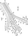
- a drainage manifold 302may have a longitudinal axis 350 and may include a plurality of elongate members 352, an elongate support 354, and a plurality of sacrificial webs 356.
- Each of the elongate members 352may have a first end 358, a second end 360, and an outer wall 362.
- the first end 358 of each of the elongate members 352may be moveable between a gathered position and a dispersed position relative to the longitudinal axis 350 of the drainage manifold 302.
- each of the elongate members 352When the first end 358 of each of the elongate members 352 is in the gathered position, the elongate members 352 may be releaseably secured longitudinally and circumferentially about the longitudinal axis 350 of the drainage manifold 302.
- the second end 360 of each of the elongate members 352may be coupled to the internal surface 136 of the transitional connector 104 at the first end 130 of the transitional connector 104 such that the drainage tube 106 is in fluid communication with at least the outer wall 362 of each of the elongate members 352.
- FIGS. 3A-3Ddepict four of the elongate members 352, the drainage manifold 302 may include any number of the elongate members 352 to suit a particular application.
- each of the elongate members 352may additionally include a longitudinal duct 364, a reinforced portion 372, a trimmable tip 374, and a mating surface 376.
- the longitudinal duct 364may be positioned on the outer wall 362 and between the first end 358 and the second end 360 of the elongate member 352.
- each of the elongate members 352may include a plurality of longitudinal ducts 364 positioned as described above.
- the drainage tube 106may be in fluid communication with at least the longitudinal duct 364 of each of the elongate members 352.
- Each of the elongate members 352may carry the reinforced portion 372 between the first and the second end 358, 360 of the elongate member 352.
- the reinforced portion 372may be, for example, a formable titanium wire formed integrally into each of the elongate members 352.
- Each of the elongate members 352may carry the trimmable tip 374 at the first end 358 of the elongate member 352. If equipped with the trimmable tip 374, the elongate member 352 may carry the reinforced portion 372 between the trimmable tip 374 and the second end 360 of the elongate member 352.
- the trimmable tip 374may be trimmed or otherwise cut to a desired length without exposing or otherwise interfering with the reinforced portion 372 of the elongate member 352.
- Each of the elongate members 352may carry the mating surface 376 adapted to engage the internal surface 136 of the transitional connector 104. As shown in FIGS. 3A-3D , the mating surface 376 of each of the elongate members 352 may extend longitudinally between the first and the second end 358, 360 of the elongate member 352 and on the outer wall 362 of the elongate member 352. Further, each of the elongate members 352 may include a plurality of the mating surfaces 376. In some embodiments, each of the elongate members 352 may carry the mating surface 376 on a portion of the elongate member 352 at the second end 360 for engaging the internal surface 136 of the transitional connector 104.
- each of the elongate members 352may cooperate with one another to provide an outer boundary 380 for the drainage manifold 302 that is compatible with the internal surface 136 of the transitional connector 104.
- the outer boundary 380 of the drainage manifold 302may be circular in shape and may have an outer dimension sized to interferingly engage a complementary circular shape and inner dimension of the internal surface 136 of the transitional connector 104.
- the elongate support 354may have a length and an external surface 382.
- the drainage manifold 302may carry the elongate support 354 on the longitudinal axis 350 of the drainage manifold 302.
- the elongate member 352may be releaseably secured longitudinally and circumferentially about the external surface 382 of the elongate support 354.
- the drainage tube 106may be in fluid communication with at least the external surface 382 of the elongate support 354.
- the elongate support 354may additionally include an inner lumen 386, an opening 388, and a chamfer 389.
- the elongate support 354may carry the inner lumen 386, for example, internally along the length of the elongate support 354.
- the drainage tube 106may be in fluid communication with at least the inner lumen 386 in the elongate support 354.
- the elongate support 354may have the opening 388 disposed through the external surface 382 of the elongate support 354 to provide fluid communication between the inner lumen 386 of the elongate support 354 and the external surface 382 of the elongate support 354. As shown in FIG.
- the elongate support 354may have a plurality of the openings 388 positioned along the length of the elongate support 354. Further, the elongate support 354 may have the chamfer 389 positioned on the abutting surface between the opening 388 and the external surface 382 of the elongate support 354.
- the elongate support 354may have similar elements as the elongate member 352.
- the elongate support 354may include the previously described longitudinal duct 364, the reinforced portion 372, and the trimmable tip 374.
- the elongate support 354may carry the longitudinal duct 364 along the length and on the external surface 382 of the elongate support 354. Further, the elongate support 354 may carry the trimmable tip 374 on an end of the elongate support 354 with the reinforced portion 372 positioned between the trimmable tip 374 and an opposing end of the elongate support 354.
- the drainage manifold 302may carry at least one of the sacrificial webs 356 between the elongate member 352 and the elongate support 354 to releaseably secure the elongate member 352 about the elongate support 354 when the first end 358 of the elongate member 352 is in the gathered position.
- the sacrificial web 356may be severable upon application of a force, such as a pulling force, directed to pull or otherwise separate the elongate member 352 away from the elongate support 354.
- the forcemay be applied on the elongate member 352 and directed transverse to the longitudinal axis 350 of the drainage manifold 302.
- the thickness of the sacrificial web 356may be sized such that the sacrificial web 356 may sever upon application of a threshold amount of the force, permitting the elongate member 352 to separate from the elongate support 354.
- the threshold amount of the forcemay be less than an amount of force capable of severing another component of the drainage manifold 302.
- the application of the threshold force to the elongate member 352may prevent damage to other components of the drainage manifold 302.
- each of the sacrificial webs 356may, for example, have a score or a perforation (not shown) along the length of the sacrificial web 356 that may be adapted to enhance the separation of the elongate member 352 from the elongate support 354.
- the score or perforationmay define a predictable or desired path, such as a substantially straight line, for separation of the elongate member 352 from the elongate support 354.
- the threshold force required to sever the sacrificial web 356 along the score or perforation to separate the elongate member 352 from the elongate support 354may be less than the force required to sever the sacrificial web 356 at another location.
- the plurality of the sacrificial webs 356may permit a physician, for example, to configure the drainage manifold 302 to treat a larger surface area of tissue, without a cutting instrument or other instrument, by pulling the elongate members 352 away from the elongate support 354 by hand.
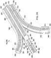
- a drainage manifold 402may have a longitudinal axis 450 and may include a plurality of elongate members 452 and a plurality of sacrificial webs 456.
- Each of the elongate members 452may have a first end 458, a second end 460, and an outer wall 462.
- the first end 458 of each of the elongate members 452may be moveable between a gathered position and a dispersed position relative to the longitudinal axis 450 of the drainage manifold 402.
- each of the elongate members 452When the first end 458 of each of the elongate members 452 is in the gathered position, the elongate members 452 may be releaseably secured longitudinally and circumferentially about the longitudinal axis 450 of the drainage manifold 402.
- the second end 460 of each of the elongate members 452may be coupled to the internal surface 136 of the transitional connector 104 at the first end 130 of the transitional connector 104 such that the drainage tube 106 may be in fluid communication with at least the outer wall 462 of each of the elongate members 452.
- FIGS. 4A-4Ddepict three of the elongate members 452, the drainage manifold 402 may include any number of the elongate members 452 to suit a particular application.
- each of the elongate members 452may have an oblong cross-sectional shape and may additionally include a longitudinal duct 464, an inner lumen 466, an opening 468, a chamfer 470, a reinforced portion 472, a trimmable tip 474, and a mating surface 476.
- the longitudinal duct 464may be positioned on the outer wall 462 and between the first end 458 and the second end 460 of the elongate member 452.
- each of the elongate members 452may include a plurality of the longitudinal ducts 464 positioned as described above.
- the drainage tube 106may be in fluid communication with at least the longitudinal duct 464 of each of the elongate members 452.
- Each of the elongate members 452may carry the inner lumen 466, for example, internally along the length of the elongate member 452 and between the first and the second end 458, 460 of the elongate member 452.
- the drainage tube 106may be in fluid communication with at least the inner lumen 466 in each of the elongate members 452.
- Each of the elongate members 452may have the opening 468 disposed through the outer wall 462 of the elongate member 452 to provide fluid communication between the inner lumen 466 of the elongate member 452 and the outer wall 462 of the elongate member 452.
- the oblong cross-sectional shape of each of the elongate members 452may enhance the ability of the elongate member 452 to resist collapsing of the inner lumen 466 when positioned at the tissue site 108.
- each of the elongate members 452may have a plurality of the openings 468 disposed through the outer wall 462 of the elongate member 452.
- the plurality of the openings 468may be positioned sequentially between the first and the second end 458, 460 of each of the elongate members 452.
- Each of the elongate members 452may have the chamfer 470 positioned on the abutting surface between the opening 468 and the outer wall 462 of the elongate member 452.
- Each of the elongate members 452may carry the reinforced portion 472 between the first and the second end 458, 460 of the elongate member 452.
- the reinforced portion 472may be, for example, a formable titanium wire formed integrally into each of the elongate members 452.
- Each of the elongate members 452may carry the trimmable tip 474 at the first end 458 of the elongate member 452. If equipped with the trimmable tip 474, the elongate member 452 may carry the reinforced portion 472 between the trimmable tip 474 and the second end 460 of the elongate member 452.
- the trimmable tip 474may be trimmed or otherwise cut to a desired length without exposing or otherwise interfering with the reinforced portion 472 of the elongate member 452.
- Each of the elongate members 452may carry the mating surface 476 that may be adapted to engage the internal surface 136 of the transitional connector 104. As shown in FIGS. 4A-4D , the mating surface 476 of each of the elongate members 452 may extend longitudinally between the first and the second end 458, 460 of the elongate member 452 and on the outer wall 462 of the elongate member 452. Further, each of the elongate members 452 may include a plurality of the mating surfaces 476. In some embodiments, each of the elongate members 452 may carry the mating surface 476 on a portion of the elongate member 452 at the second end 460 for engaging the internal surface 136 of the transitional connector 104.
- each of the elongate members 452may cooperate with one another to provide an outer boundary 480 for the drainage manifold 402 that is compatible with the internal surface 136 of the transitional connector 104.
- the outer boundary 480 of the drainage manifold 402may be circular in shape and may have an outer dimension sized to interferingly engage a complementary circular shape and inner dimension of the internal surface 136 of the transitional connector 104.
- the drainage manifold 402may carry the sacrificial webs 456 circumferentially about the longitudinal axis 450 of the drainage manifold 402 and between the elongate members 452 to releaseably secure the elongate members 452 to one another when the first end 458 of each of the elongate members 452 is in the gathered position.
- each of the elongate members 452may have an oblong cross-sectional shape having a width dimension greater than a height dimension.
- Each of the elongate members 452may have a pair of opposing sides 492 separated by the width of the elongate member 452.
- each of the sides 492 of one of the elongate members 452may be adjacent one of the sides 492 of another elongate member 452.
- the drainage manifold 402may carry at least one of the sacrificial webs 456 between the adjacent sides 492 of the elongate members 452.
- Each of the sacrificial webs 456may be severable upon application of a force, such as a pulling force, directed to pull or otherwise separate one of the elongate members 452 away from another of the elongate members 452.
- a forcesuch as a pulling force
- the forcemay be applied on one of the elongate members 452 and directed transverse to the longitudinal axis 450 of the drainage manifold 402.
- the thickness of the sacrificial web 456may be sized such that the sacrificial web 456 may sever upon application of a threshold amount of the force, permitting the elongate member 452 to separate from the other elongate members 452.
- each of the sacrificial webs 456may, for example, have a score or a perforation (not shown) along the length of the sacrificial web 456 that may be adapted to enhance the separation of the elongate members 452 from one another.
- the score or perforationmay define a predictable or desired path, such as a substantially straight line, for the separation of the elongate members 452 from one another.
- the threshold force required to sever the sacrificial web 456 along the score or perforation to separate the elongate members 452 from one anothermay be less than the force required to sever the sacrificial web 456 at another location.
- the plurality of the sacrificial webs 456may permit a physician, for example, to configure the drainage manifold 402 to treat a larger surface area, without a cutting instrument or other instrument, by pulling the elongate members 452 away from one another and away from the longitudinal axis 450 of the drainage manifold 402.
- each of the elongate members 452may cooperate with one another and with each of the sacrificial webs 456 to define a central lumen 494 in the drainage manifold 402 when the first end 458 of each of the elongate members 452 is in the gathered position.
- the drainage tube 106may be in fluid communication with at least the central lumen 494 in the drainage manifold 402.
- at least one of the sacrificial webs 456may coincide with at least one of the longitudinal ducts 464.
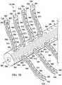
- the drainage manifold 502may have a longitudinal axis 550 and may include a plurality of elongate members 552 and an elongate support 554.
- the elongate support 554may have a length and an external surface 582 positioned on the longitudinal axis 550 of the drainage manifold 502.
- Each of the elongate members 552may have a first end 558, a second end 560, and an outer wall 562.
- the first end 558 of each of the elongate members 552may be moveable relative to the elongate support 554.
- the second end 560 of each of the elongate members 552may be secured about the external surface 582 of the elongate support 554.
- the elongate support 554may be coupled to the internal surface 136 of the transitional connector 104 at the first end 130 of the transitional connector 104 such that the drainage tube 106 may be in fluid communication with at least the outer wall 562 of each of the elongate members 552 and the external surface 582 of the elongate support 554.
- the drainage manifold 502may include any number of the elongate members 552 to suit a particular application. Further, the elongate members 552 may form an angle (not shown) relative to the elongate support 554, such as, for example, an angle of about 45 degrees measured between the elongate member 552 and the elongate support 554. The angle may reduce the trauma experienced by the patient upon withdrawal of the drainage manifold 502.
- each of the elongate members 552may additionally include a longitudinal duct 564, an inner lumen 566, an opening 568, a chamfer 570, a reinforced portion 572, and a trimmable tip 574.
- the longitudinal duct 564may be positioned on the outer wall 562 and between the first end 558 and the second end 560 of the elongate member 552.
- each of the elongate members 552may include a plurality of the longitudinal ducts 564 positioned as described above.
- the drainage tube 106may be in fluid communication with at least the longitudinal duct 564 of each of the elongate members 552.
- Each of the elongate members 552may carry the inner lumen 566, for example, internally along the length of the elongate member 552 and between the first and the second end 558, 560 of the elongate member 552.
- the drainage tube 106may be in fluid communication with at least the inner lumen 566 in each of the elongate members 552.
- Each of the elongate members 552may have the opening 568 disposed through the outer wall 562 of the elongate member 552 to provide fluid communication between the inner lumen 566 of the elongate member 552 and the outer wall 562 of the elongate member 552.
- each of the elongate members 552may have a plurality of the openings 568 disposed through the outer wall 562 of the elongate member 552.
- Each of the elongate members 552may have the chamfer 570 positioned on the abutting surface between the opening 568 and the outer wall 562 of the elongate member 552.
- Each of the elongate members 552may carry the reinforced portion 572 between the first and the second end 558, 560 of the elongate member 552.
- the reinforced portion 572may be, for example, a formable titanium wire formed integrally into each of the elongate members 552.
- Each of the elongate members 552may carry the trimmable tip 574 at the first end 558 of the elongate member 552. If equipped with the trimmable tip 574, the elongate member 552 may carry the reinforced portion 572 between the trimmable tip 574 and the second end 560 of the elongate member 552.
- the trimmable tip 574may be trimmed or otherwise cut to a desired length without exposing or otherwise interfering with the reinforced portion 572 of the elongate member 552.
- the elongate support 554may additionally include a plurality of longitudinal protrusions 584, an inner lumen 586, an opening 588, and a chamfer 589.
- the elongate support 554may carry the plurality of longitudinal protrusions 584 on the external surface 582 and along the length of the elongate support 554.
- the longitudinal protrusions 584 and the external surface 582cooperate to define at least one longitudinal groove 590.
- the drainage tube 106may be in fluid communication with at least the longitudinal groove 590.
- the elongate support 554may carry the inner lumen 586, for example, internally along the length of the elongate support 554.
- the drainage tube 106may be in fluid communication with at least the inner lumen 586 in the elongate support 554 and the outer wall 562 of each of the elongate members 552.
- the elongate support 554may have the opening 588 disposed through the external surface 582 of the elongate support 554 to provide fluid communication between the inner lumen 586 of the elongate support 554 and the external surface 582 of the elongate support 554.
- the elongate support 554may have a plurality of the openings 588 positioned along the length of the elongate support 554.
- the elongate support 554may have the chamfer 589 positioned on the abutting surface between the opening 588 and the external surface 582 of the elongate support 554.
- insertion of the drainage tube 106 through the incision 120occurs with the drainage tube 106 beginning at the tissue site 108 and proceeding through the subcutaneous tissue 126, the dermis 124, and subsequently protruding through the epidermis 122.
- the drainage tube 106may be draped with an external sealing member (not shown) in any suitable manner to enhance the seal of the drainage tube about the epidermis 122, external to the incision 120.
- the sealing membermay be, for example, an adhesive polyurethane sheet or any material capable of providing a fluid seal suitable to maintain reduced pressure at the tissue site 108. As shown in FIG.
- the transitional connector 104may reside between the incision 120 and the tissue site 108, thereby permitting the incision 120 to seal about the drainage tube 106 at the epidermis 122 without requiring the external sealing member described above. In some embodiments, the transitional connector 104 may reside exterior to the incision 120 and the epidermis 122.
- the drainage manifold 102, 202, 302, 402, 502may be configured to treat a large surface area at the tissue site 108 by hand and without the need for an instrument or tool.
- the elongate members 252, 352, 452may be separated as described above and positioned, for example, in the cavities 116 and between the tissue layers 118 in and around the tissue site 108.
- the elongate members 552may be moved about the elongate support 554 and positioned in and around the tissue site 108 in a similar manner as described above.
- the reinforced portion 272, 372, 472, 572may enhance the ability of the elongate members 252, 352, 452, 552 to retain a desired shape when positioned at the tissue site 108. Forming the reinforced portion 272, 372, 472, 572 into a desired shape may enhance the ability of a physician, for example, to configure the drainage manifold 102, 202, 302, 402, 502 to remain in fluid communication with the cavities 116 and the tissue layers 118 that may be present at the tissue site 108.
- the tissue site 108may have a unique size and shape requiring the drainage manifold 102, 202, 302, 402, 502 to be configured and positioned in a particular manner to reduce the possibility for fluids to become trapped at the tissue site 108.
- Fluidsmay become trapped at the tissue site 108, for example, in the cavities 116 and between the tissue layers 118 if the drainage manifold 102, 202, 302, 402, 502 does not remain in fluid communication with the cavities 116 and the tissue layers 118. Fluids trapped at the tissue site 108 may increase the chance for seroma or hematoma to occur.
- the physicianmay optionally utilize, for example, a biodegradable suture material and/or two-dimensional mesh material to secure the elongate members 252, 352, 452, 552 in and around the tissue site 108.
- the trimmable tip 274, 374, 474, 574may provide a portion of each of the respective elongate members 252, 352, 452, 552 suitable for trimming to a desired size to fit in and around the tissue site 108. Trimming the trimmable tip 274, 374, 474, 574 may not interfere with the reinforced portion 272, 372, 472, 572 or the operation of the drainage manifold 102, 202, 302, 402, 502.
- the reduced-pressure source 110may be in fluid communication with the drainage manifold 102, 202, 302, 402, 502.
- the drainage manifold 102, 202, 302, 402, 502may be positioned at the tissue site 108 as described above and may be adapted to distribute reduced pressure from the reduced-pressure source 110 to the tissue site 108.
- Providing reduced pressure from the reduced-pressure source 110 to the drainage manifold 102, 202, 302, 402, 502 and the tissue site 108may extract fluid from the tissue site 108.
- distributing the reduced pressure to the tissue site 108may exert force on the tissue site 108 that, for example, may draw the cavities 116 and the tissue layers 118 together and around the components of the drainage manifold 102, 202, 302, 402, 502.
- the drainage tube 106may remain in fluid communication with the components of the drainage manifold 102, 202, 302, 402, 502 as previously described.
- the components of the drainage manifold 102, 202, 302, 402, 502may provide a separation or a fluid passageway between the drainage manifold 102, 202, 302, 402, 502 and, for example, the tissue layers 118.
- the previously described components of the drainage manifold 102, 202, 302, 402, 502 positioned at the tissue site 108may cooperate with the tissue site 108 to form a network of fluid passageways with the tissue site 108 when the reduced pressure is applied. Fluid extracted from the tissue site 108 may travel in and along the fluid passageways and the previously described components of the drainage manifold 102, 202, 302, 402, 502 to the transitional connector 104 and through the drainage tube 106. The fluid may exit the drainage tube 106 into the fluid canister 112 for storage and disposal.
- the drainage manifold 102, 202, 302, 402, 502may be withdrawn from the tissue site 108 by applying traction or otherwise pulling on the drainage tube 106, thereby withdrawing the transitional connector 104 and the drainage manifold 102, 202, 302, 402, 502 through the incision 120.
- the drainage manifold 202, 302, 402may retain a shape substantially similar to the shape of the drainage manifold 202, 302, 402 prior to placement at the tissue site 108.
- the previously described components of the drainage manifold 202, 302, 402may, upon withdrawal, retain the previously described configuration about the respective longitudinal axis 250, 350, 450 of the drainage manifold 202, 302, 402. In this manner, the drainage manifold 202, 302, 402 may reduce pain experienced by the patient during withdrawal.
Landscapes
- Health & Medical Sciences (AREA)
- Heart & Thoracic Surgery (AREA)
- Life Sciences & Earth Sciences (AREA)
- Engineering & Computer Science (AREA)
- Biomedical Technology (AREA)
- Animal Behavior & Ethology (AREA)
- General Health & Medical Sciences (AREA)
- Public Health (AREA)
- Veterinary Medicine (AREA)
- Hematology (AREA)
- Anesthesiology (AREA)
- Vascular Medicine (AREA)
- Otolaryngology (AREA)
- Biophysics (AREA)
- Pulmonology (AREA)
- External Artificial Organs (AREA)
- Media Introduction/Drainage Providing Device (AREA)
Description
- The subject matter disclosed herein relates generally to medical wound care systems, and more particularly, but not by way of limitation, to wound drainage devices, systems, and methods. The devices, systems, and methods disclosed may provide increased configurability for adapting to multi-dimensional wounds, and may be particularly suitable for use with reduced pressure to enhance the drainage of fluids from the wound.
- Common wound drainage devices, systems, and methods typically require multiple incision sites in a patient to provide treatment for a multi-dimensional wound that may have a large surface area or an unusual shape. Further, known devices, systems, and methods are typically difficult to configure and seal at the wound site, and can cause damage to tissue and pain for the patient upon removal. Document
US 2011/054283 discloses a wound drainage system for draining liquid from an area underneath a drape by providing suction through holes in elongate members facing away from the drape. - Thus, improvements to wound drainage devices, systems, and methods that provide increased configurability and ease of placement for treatment of multi-dimensional wounds while reducing the potential for damage to tissue and pain for the patient are desirable. Such improvements may reduce the chance of infection, improve cosmetic appearance, reduce the pooling of fluids, and reduce the potential for seroma or hematoma.
- Shortcomings with certain aspects of wound drainage devices, systems, and methods are addressed as shown and described in a variety of illustrative, non-limiting embodiments herein.
- According to an illustrative, non-limiting embodiment, a drainage system for draining fluid from a tissue site may include a drainage manifold, a transitional connector, and a drainage tube. The drainage manifold may have a longitudinal axis and may include a plurality of elongate members each having a first end, a second end, and an outer wall. The first end of each of the elongate members may be moveable between a gathered position and a dispersed position relative to the longitudinal axis of the drainage manifold. When the first end of each of the elongate members is in the gathered position, the elongate members may be releaseably secured longitudinally and circumferentially about the longitudinal axis of the drainage manifold. Each of the elongate members may further include a longitudinal duct and a reinforced portion. The longitudinal duct may be positioned on the outer wall and between the first end and the second end of the elongate members. The reinforced portion may be positioned between the first end and the second end of the elongate members. The transitional connector may have a first end and an opposing second end. The first end of the transitional connector may be coupled to the drainage manifold. The drainage tube may be coupled to the second end of the transitional connector and in fluid communication with the drainage manifold and the longitudinal duct of each of the elongate members.
- According to another illustrative, non-limiting embodiment, a drainage system for draining fluid from a tissue site may include a drainage manifold, a transitional connector, and a drainage tube. The drainage manifold may have a longitudinal axis and may include an elongate support, a plurality of elongate members, and a plurality of sacrificial webs. The elongate support may have a length and an external surface. The length of the elongate support may be positioned on the longitudinal axis of the drainage manifold. The plurality of elongate members may each have a first end, a second end, and an outer wall. The first end of each of the elongate members may be moveable between a gathered position and a dispersed position relative to the longitudinal axis of the drainage manifold. When the first end of the elongate member is in the gathered position, the elongate member may be releaseably secured longitudinally and circumferentially about the external surface of the elongate support. Each of the elongate members may further include a longitudinal duct positioned on the outer wall and between the first end and the second end of the elongate member. At least one of the plurality of sacrificial webs may be positioned between the elongate member and the elongate support to releaseably secure the elongate member about the elongate support when the first end of the elongate member is in the gathered position. The transitional connector may have a first end and an opposing second end. The first end of the transitional connector may be coupled to the drainage manifold. The drainage tube may be coupled to the second end of the transitional connector and in fluid communication with the drainage manifold and the longitudinal duct of each of the elongate members.
- According to yet another illustrative, non-limiting embodiment, a drainage manifold for draining fluid from a tissue site may have a longitudinal axis and may include an elongate support, a plurality of elongate members, and a plurality of sacrificial webs. The elongate support may have a length, an external surface, and an inner lumen. The length of the elongate support may be positioned on the longitudinal axis of the drainage manifold. The plurality of elongate members may each have a first end, a second end, and an outer wall. The first end of each of the elongate members may be moveable between a gathered position and a dispersed position relative to the longitudinal axis of the drainage manifold. When the first end of the elongate member is in the gathered position, the elongate member may be releaseably secured longitudinally and circumferentially about the external surface of the elongate support. Each of the elongate members may further include a longitudinal duct positioned on the outer wall and between the first end and the second end of the elongate member, an inner lumen, and an opening disposed through the outer wall. The opening may provide fluid communication between the inner lumen of the elongate member and the outer wall. At least one of the plurality of sacrificial webs may be positioned between the elongate member and the elongate support to releaseably secure the elongate member about the elongate support when the first end of the elongate member is in the gathered position.
- According to still another illustrative, non-limiting embodiment, a drainage system for draining fluid from a tissue site may include a drainage manifold, a reduced-pressure source, and a fluid canister. The drainage manifold may include an elongate support and a plurality of elongate members. The elongate support may have a length, an external surface, an inner lumen, and a plurality of openings disposed through the external surface to provide fluid communication between the external surface and the inner lumen. The plurality of elongate members may each have a first end, a second end, and an outer wall. The first end of each of the elongate members may be moveable relative to the elongate support. The second end of each of the elongate members may be secured about the external surface of the elongate support. The outer wall of each of the elongate members may be in fluid communication with the inner lumen in the elongate support. The reduced-pressure source may be fluidly coupled to the elongate support and adapted to provide a reduced pressure to the drainage manifold and the inner lumen in the elongate support. The fluid canister may be positioned in fluid communication between the elongate support and the reduced-pressure source. The fluid canister may be adapted to retain fluid communicated from the drainage manifold.
- Other features and advantages of the illustrative embodiments will become apparent with reference to the drawings and detailed description that follow.
- A more complete understanding of this specification may be obtained by reference to the following detailed description when taken in conjunction with the accompanying drawings, wherein:
FIG. 1 is a perspective view of an illustrative embodiment of a drainage system applied to a tissue site;FIG. 2A is a perspective, cut-away view of an illustrative embodiment of a drainage system depicting a drainage manifold having a plurality of elongate members in a gathered position;FIG. 2B is a perspective view of the drainage manifold ofFIG. 2A , illustrating the plurality of elongate members in a dispersed position;FIG. 2C is a cross-section view of the drainage manifold ofFIG. 2A taken atline 2C-2C;FIG. 2D is a cross-section view of the drainage manifold ofFIG. 2A taken atline 2D-2D;FIG. 3A is a perspective, cut-away view of another illustrative embodiment of a drainage system depicting a drainage manifold having a plurality of elongate members in a gathered position;FIG. 3B is a perspective view of the drainage manifold ofFIG. 3A , illustrating the plurality of elongate members in a dispersed position;FIG. 3C is a cross-section view of the drainage manifold ofFIG. 3A taken atline 3C-3C;FIG. 3D is a cross-section view of the drainage manifold ofFIG. 3A taken atline 3D-3D;FIG. 4A is a perspective, cut-away view of another illustrative embodiment of a drainage system depicting a drainage manifold having a plurality of elongate members in a gathered position;FIG. 4B is a perspective view of the drainage manifold ofFIG. 4A , illustrating the plurality of elongate members in a dispersed position;FIG. 4C is a cross-section view of the drainage manifold ofFIG. 4A taken atline 4C-4C;FIG. 4D is a cross-section view of the drainage manifold ofFIG. 4A taken atline 4D-4D;FIG. 5A is a perspective, cut-away view of another illustrative embodiment of a drainage system depicting a drainage manifold having a plurality of elongate members; andFIG. 5B is a perspective view of the drainage manifold depicted inFIG. 5A .- In the following detailed description of the non-limiting, illustrative embodiments, reference is made to the accompanying drawings that form a part hereof. Other embodiments may be utilized and logical, structural, mechanical, electrical, and chemical changes may be made without departing from the scope of this specification. To avoid detail not necessary to enable those skilled in the art to practice the embodiments described herein, the detailed description may omit certain information known to those skilled in the art. The following detailed description is, therefore, provided without limitation and with the scope of the illustrative embodiments being defined by the appended claims. As used herein, unless otherwise indicated, "or" does not require mutual exclusivity.
- Referring generally to drawing
FIGS. 1-5B , depicted therein are illustrative embodiments of adrainage system 100 that may include adrainage manifold 102, atransitional connector 104, and adrainage tube 106. Thedrainage system 100 may be particularly suitable for treating a tissue site 108, and may utilize reduced pressure to enhance the drainage of fluids from the tissue site 108. Thus, thedrainage system 100 may additionally include a reduced-pressure source 110 adapted to provide reduced pressure as part of thedrainage system 100. Further, thedrainage system 100 may include afluid canister 112 adapted to retain fluid extracted from, for example, the tissue site 108. - The tissue site 108 may be, for example, a multi-dimensional tissue site 114 that may include
multiple cavities 116 requiring drainage or treatment. Thecavities 116 may be positioned or otherwise formed between multiple tissue layers 118. As depicted inFIG. 1 , for example, thedrainage system 100 may be applied to the tissue site 108 through anincision 120 that extends through or otherwise involvesepidermis 122,dermis 124, andsubcutaneous tissue 126. Thedrainage system 100 may be utilized at other tissue sites. - The tissue site 108 may be the bodily tissue of any human, animal, or other organism, including bone tissue, adipose tissue, muscle tissue, dermal tissue, vascular tissue, connective tissue, cartilage, tendons, ligaments, or any other tissue. Treatment of the tissue site 108 may include the removal of fluids, such as, for example, exudate or ascites, or the instillation of fluid to the tissue site 108.
- As used herein, "reduced pressure" generally refers to a pressure less than the ambient pressure at the tissue site 108 being subjected to treatment. This reduced pressure may be less than the atmospheric pressure. In some embodiments, the reduced pressure may be less than a hydrostatic pressure at a tissue site. Unless otherwise indicated, values of pressure stated herein are gauge pressures. While the amount and nature of reduced pressure applied to a tissue site may vary according to the application, the reduced pressure may be between about -5 mm Hg to about -500 mm Hg. In some embodiments, the reduced pressure may be in a therapeutic range between about -100 mm Hg to about -200 mm Hg.
- The reduced pressure delivered may be constant or varied, patterned or random, and may be delivered continuously or intermittently. Although the terms "vacuum" and "negative pressure" may be used to describe the pressure applied to a tissue site, the actual pressure applied to a tissue site may be more than the pressure normally associated with a complete vacuum. Consistent with the use herein, an increase in reduced pressure or vacuum pressure typically refers to a relative reduction in absolute pressure.
- In the embodiments of
FIGS. 1-5B , the reduced-pressure source 110 may be fluidly coupled to thedrainage tube 106. Thedrainage tube 106 may be in fluid communication with thetransitional connector 104 and thedrainage manifold 102 as will be described below. Further, thefluid canister 112 may be fluidly coupled between thedrainage tube 106 and the reduced-pressure source 110. As shown, thedrainage tube 106 may be fluidly coupled to thefluid canister 112. Afluid conduit 128 may be coupled between thefluid canister 112 and the reduced-pressure source 110 to provide fluid communication and reduced pressure from the reduced-pressure source 110 to, for example, thefluid canister 112, thedrainage tube 106, thetransitional connector 104, and thedrainage manifold 102. Thedrainage tube 106 and thefluid conduit 128 may be coupled to an upper portion of thefluid canister 112 to prevent the reduced pressure from interfering with fluid collecting at a lower portion of thefluid canister 112. - As used herein, the term "coupled" may include coupling with a separate object or direct coupling. The term "coupled" may also encompass two or more components that are continuous with one another by virtue of each of the components being formed from the same piece of material. Also, the term "coupled" may include chemical coupling, such as with a chemical bond, or mechanical, thermal, or electrical coupling. Fluid coupling may refer to a coupling permitting fluid to be in communication between the designated parts or locations.
- The reduced-
pressure source 110 may be any suitable device for providing reduced pressure as described herein, such as, for example, a vacuum pump, wall suction, or other source. Thefluid canister 112 may be any suitable containment device capable of retaining fluid and communicating reduced pressure from the reduced-pressure source 110 to other components of thedrainage system 100, such as thedrainage manifold 102. - In some embodiments, one or more monitoring devices (not shown) may be fluidly coupled to the
drainage system 100. The monitoring devices may be, for example, a pressure-feedback device, a volume detection system, a blood detection system, an infection detection system, a flow monitoring system, a temperature monitoring system, or similar device. In some embodiments, the monitoring devices may be formed integrally with the reduced-pressure source 110. - The
transitional connector 104 may have afirst end 130, an opposingsecond end 132, acenter 134 positioned substantially equidistant between thefirst end 130 and thesecond end 132, aninternal surface 136, and anexternal surface 138. Thefirst end 130 of thetransitional connector 104 may be fluidly coupled to thedrainage manifold 102, and thesecond end 132 of thetransitional connector 104 may be fluidly coupled to thedrainage tube 106. Thus, thedrainage tube 106 may be in fluid communication with thedrainage manifold 102. Thetransitional connector 104 may be adapted to provide a smooth external profile between thedrainage manifold 102 and thedrainage tube 106. For example, in some embodiments, thetransitional connector 104 may have afirst taper 140 and an opposingsecond taper 142. Thefirst taper 140 may provide a tapered transition from an outside diameter at thecenter 134 of thetransitional connector 104 to a smaller outside diameter at thefirst end 130 of thetransitional connector 104. Similarly, thesecond taper 142 may provide a tapered transition from the outside diameter at thecenter 134 to a smaller outside diameter at thesecond end 132 of thetransitional connector 104. Thefirst taper 140 and thesecond taper 142 may have any shape or angle to provide an external profile for thetransitional connector 104 suitable for a particular application. In other embodiments, thetransitional connector 104 may be omitted and thedrainage manifold 102 may be coupled to thedrainage tube 106 or formed integrally with thedrainage tube 106. Further, in some embodiments, theexternal surface 138 and theinternal surface 136 of thetransitional connector 104 may have a substantially circular cross-section. - The
drainage manifold 102, thetransitional connector 104, and thedrainage tube 106 may be formed, for example, from a soft polymer or other pliable material. As non-limiting examples, thedrainage manifold 102, thetransitional connector 104, and thedrainage tube 106 may be formed from a silicone elastomer, polyurethane, polyethylene, polypropylene, polyvinyl chloride (PVC), fluorosilicone, ethylene-propylene, acrylic, or similar material. In some embodiments, thedrainage manifold 102 may be extruded from DEHP-free PVC. In another embodiment, thedrainage manifold 102, thetransitional connector 104, and thedrainage tube 106 may be molded, casted, or extruded, and may be formed as an integral unit. In yet another embodiment, thetransitional connector 104 may be a silicone curable adhesive bonded joint for coupling thedrainage manifold 102 and thedrainage tube 106 to one another. To suit a particular application, thedrainage manifold 102 may additionally include color-coding, materials for X-Ray detection, graduation markings, and coatings to reduce clogging and the presence of bacteria. - Referring now to the embodiments of
FIGS. 2A-2D , a drainage manifold 202 may have alongitudinal axis 250 and may include a plurality ofelongate members 252, anelongate support 254, and a plurality ofsacrificial webs 256. Each of theelongate members 252 may have afirst end 258, asecond end 260, and anouter wall 262. Thefirst end 258 of each of theelongate members 252 may be moveable between a gathered position and a dispersed position relative to thelongitudinal axis 250 of the drainage manifold 202. When thefirst end 258 of each of theelongate members 252 is in the gathered position, theelongate members 252 may be releaseably secured longitudinally and circumferentially about thelongitudinal axis 250 of the drainage manifold 202. Thesecond end 260 of each of theelongate members 252 may be coupled to theinternal surface 136 of thetransitional connector 104 and at thefirst end 130 of thetransitional connector 104 such that thedrainage tube 106 is in fluid communication with at least theouter wall 262 of each of theelongate members 252. AlthoughFIGS. 2A-2D depict three of theelongate members 252, the drainage manifold 202 may include any number of theelongate members 252 to suit a particular application. - As shown in
FIGS. 2A-2D , each of theelongate members 252 may have an oblong cross-sectional shape and may additionally include alongitudinal duct 264, aninner lumen 266, an opening 268, achamfer 270, a reinforcedportion 272, atrimmable tip 274, and amating surface 276. Thelongitudinal duct 264 may be positioned on theouter wall 262 and between thefirst end 258 and thesecond end 260 of theelongate member 252. As shown inFIGS. 2A-2D , each of theelongate members 252 may include a plurality oflongitudinal ducts 264 positioned as described above. Thedrainage tube 106 may be in fluid communication with at least thelongitudinal duct 264 of each of theelongate members 252. - Each of the
elongate members 252 may carry theinner lumen 266, for example, internally along the length of theelongate member 252 and between the first and thesecond end elongate member 252. Thedrainage tube 106 may be in fluid communication with at least theinner lumen 266 in each of theelongate members 252. Each of theelongate members 252 may have the opening 268 disposed through theouter wall 262 of theelongate member 252 to provide fluid communication between theinner lumen 266 of theelongate member 252 and theouter wall 262 of theelongate member 252. The oblong cross-sectional shape of each of theelongate members 252 may enhance the ability of theelongate member 252 to resist collapsing of theinner lumen 266 when positioned at the tissue site 108. - As shown in
FIGS. 2A-2D , the opening 268 may be a longitudinal channel 278 positioned between the first and thesecond end elongate member 252. In another embodiment, each of theelongate members 252 may have a plurality of the openings 268 disposed through theouter wall 262 of theelongate member 252. Each of theelongate members 252 may have thechamfer 270 positioned on the abutting surface between the opening 268 and theouter wall 262 of theelongate member 252. - Each of the
elongate members 252 may carry the reinforcedportion 272 between the first and thesecond end elongate member 252. The reinforcedportion 272 may be, for example, a formable titanium wire formed integrally into each of theelongate members 252. Each of theelongate members 252 may carry thetrimmable tip 274 at thefirst end 258 of theelongate member 252. If equipped with thetrimmable tip 274, theelongate member 252 may carry the reinforcedportion 272 between thetrimmable tip 274 and thesecond end 260 of theelongate member 252. Thus, thetrimmable tip 274 may be trimmed or otherwise cut to a desired length without exposing or otherwise interfering with the reinforcedportion 272 of theelongate member 252. - Each of the
elongate members 252 may carry themating surface 276 that may be adapted to engage theinternal surface 136 of thetransitional connector 104. As shown inFIGS. 2A-2D , themating surface 276 of each of theelongate members 252 may extend longitudinally between the first and thesecond end elongate member 252 and on theouter wall 262 of theelongate member 252. Further, each of theelongate members 252 may include a plurality of the mating surfaces 276. In another embodiment, each of theelongate members 252 may carry themating surface 276 on a portion of theelongate member 252 at thesecond end 260 for engaging theinternal surface 136 of thetransitional connector 104. Themating surface 276 of each of theelongate members 252 may cooperate with one another to provide anouter boundary 280 for the drainage manifold 202 that may be compatible with theinternal surface 136 of thetransitional connector 104. For example, as shown inFIGS. 2C-2D , theouter boundary 280 of the drainage manifold 202 may be circular in shape and may have an outer dimension sized to interferingly engage a complementary circular shape and inner dimension of theinternal surface 136 of thetransitional connector 104. - The
elongate support 254 may have a length and anexternal surface 282. The drainage manifold 202 may carry theelongate support 254 on thelongitudinal axis 250 of the drainage manifold 202. When thefirst end 258 of theelongate member 252 is in the gathered position described above, theelongate member 252 may be releaseably secured longitudinally and circumferentially about theexternal surface 282 of theelongate support 254. Thedrainage tube 106 may be in fluid communication with at least theexternal surface 282 of theelongate support 254. - As shown in
FIGS. 2A-2D , theelongate support 254 may additionally include a plurality oflongitudinal protrusions 284, aninner lumen 286, anopening 288, and achamfer 289. Theelongate support 254 may carry the plurality oflongitudinal protrusions 284 on theexternal surface 282 and along the length of theelongate support 254. Thelongitudinal protrusions 284 and theexternal surface 282 may cooperate to define at least onelongitudinal groove 290. Thedrainage tube 106 may be in fluid communication with at least thelongitudinal groove 290. - The
elongate support 254 may carry theinner lumen 286, for example, internally along the length of theelongate support 254. Thedrainage tube 106 may be in fluid communication with at least theinner lumen 286 in theelongate support 254. Theelongate support 254 may have theopening 288 disposed through theexternal surface 282 of theelongate support 254 to provide fluid communication between theinner lumen 286 of theelongate support 254 and theexternal surface 282 of theelongate support 254. As shown inFIG. 2B , theelongate support 254 may have a plurality of theopenings 288 positioned along the length of theelongate support 254. Further, theelongate support 254 may have thechamfer 289 positioned on the abutting surface between theopening 288 and theexternal surface 282 of theelongate support 254. - The drainage manifold 202 may carry at least one of the
sacrificial webs 256 between theelongate member 252 and theelongate support 254 to releaseably secure theelongate member 252 about theelongate support 254 when thefirst end 258 of theelongate member 252 is in the gathered position. Thesacrificial web 256 may be severable upon application of a force, such as a pulling force, directed to pull or otherwise separate theelongate member 252 away from theelongate support 254. For example, the force may be applied on theelongate member 252 and directed transverse to thelongitudinal axis 250 of the drainage manifold 202. The thickness of thesacrificial web 256 may be sized such that thesacrificial web 256 may sever upon application of a threshold amount of the force, permitting theelongate member 252 to separate from theelongate support 254. In some embodiments, the threshold amount of the force may be less than an amount of force required to sever another component of the drainage manifold 202. Thus, the application of the threshold force to theelongate member 252 may prevent damage to other components of the drainage manifold 202. In some embodiments, each of thesacrificial webs 256 may, for example, have a score or a perforation (not shown) that may be positioned along the length of thesacrificial web 256 and adapted to enhance the separation of theelongate member 252 from theelongate support 254. For example, the score or perforation may enhance the separation of theelongate member 252 from theelongate support 254 along a predictable or desired path defined by the score or perforation such as, for example, a substantially straight line. The threshold force required to sever thesacrificial web 256 along the score or perforation to separate theelongate member 252 from theelongate support 254 may be less than the force required to sever thesacrificial web 256 at another location. The plurality of thesacrificial webs 256 may permit a physician, for example, to configure the drainage manifold 202 to treat a larger surface area, without a cutting instrument or other instrument, by pulling theelongate members 252 away from theelongate support 254 by hand. - Referring now to the embodiments of
FIGS. 3A-3D , a drainage manifold 302 may have a longitudinal axis 350 and may include a plurality ofelongate members 352, anelongate support 354, and a plurality ofsacrificial webs 356. Each of theelongate members 352 may have afirst end 358, asecond end 360, and anouter wall 362. Thefirst end 358 of each of theelongate members 352 may be moveable between a gathered position and a dispersed position relative to the longitudinal axis 350 of the drainage manifold 302. When thefirst end 358 of each of theelongate members 352 is in the gathered position, theelongate members 352 may be releaseably secured longitudinally and circumferentially about the longitudinal axis 350 of the drainage manifold 302. Thesecond end 360 of each of theelongate members 352 may be coupled to theinternal surface 136 of thetransitional connector 104 at thefirst end 130 of thetransitional connector 104 such that thedrainage tube 106 is in fluid communication with at least theouter wall 362 of each of theelongate members 352. AlthoughFIGS. 3A-3D depict four of theelongate members 352, the drainage manifold 302 may include any number of theelongate members 352 to suit a particular application. - As shown in
FIGS. 3A-3D , each of theelongate members 352 may additionally include alongitudinal duct 364, a reinforcedportion 372, atrimmable tip 374, and amating surface 376. Thelongitudinal duct 364 may be positioned on theouter wall 362 and between thefirst end 358 and thesecond end 360 of theelongate member 352. As shown inFIGS. 3A-3D , each of theelongate members 352 may include a plurality oflongitudinal ducts 364 positioned as described above. Thedrainage tube 106 may be in fluid communication with at least thelongitudinal duct 364 of each of theelongate members 352. - Each of the
elongate members 352 may carry the reinforcedportion 372 between the first and thesecond end elongate member 352. The reinforcedportion 372 may be, for example, a formable titanium wire formed integrally into each of theelongate members 352. Each of theelongate members 352 may carry thetrimmable tip 374 at thefirst end 358 of theelongate member 352. If equipped with thetrimmable tip 374, theelongate member 352 may carry the reinforcedportion 372 between thetrimmable tip 374 and thesecond end 360 of theelongate member 352. Thus, thetrimmable tip 374 may be trimmed or otherwise cut to a desired length without exposing or otherwise interfering with the reinforcedportion 372 of theelongate member 352. - Each of the
elongate members 352 may carry themating surface 376 adapted to engage theinternal surface 136 of thetransitional connector 104. As shown inFIGS. 3A-3D , themating surface 376 of each of theelongate members 352 may extend longitudinally between the first and thesecond end elongate member 352 and on theouter wall 362 of theelongate member 352. Further, each of theelongate members 352 may include a plurality of the mating surfaces 376. In some embodiments, each of theelongate members 352 may carry themating surface 376 on a portion of theelongate member 352 at thesecond end 360 for engaging theinternal surface 136 of thetransitional connector 104. Themating surface 376 of each of theelongate members 352 may cooperate with one another to provide anouter boundary 380 for the drainage manifold 302 that is compatible with theinternal surface 136 of thetransitional connector 104. For example, as shown inFIGS. 3C-3D , theouter boundary 380 of the drainage manifold 302 may be circular in shape and may have an outer dimension sized to interferingly engage a complementary circular shape and inner dimension of theinternal surface 136 of thetransitional connector 104. - The
elongate support 354 may have a length and anexternal surface 382. The drainage manifold 302 may carry theelongate support 354 on the longitudinal axis 350 of the drainage manifold 302. When thefirst end 358 of theelongate member 352 is in the gathered position described above, theelongate member 352 may be releaseably secured longitudinally and circumferentially about theexternal surface 382 of theelongate support 354. Thedrainage tube 106 may be in fluid communication with at least theexternal surface 382 of theelongate support 354. - As shown in
FIGS. 3A-3D , theelongate support 354 may additionally include aninner lumen 386, anopening 388, and achamfer 389. Theelongate support 354 may carry theinner lumen 386, for example, internally along the length of theelongate support 354. Thedrainage tube 106 may be in fluid communication with at least theinner lumen 386 in theelongate support 354. Theelongate support 354 may have theopening 388 disposed through theexternal surface 382 of theelongate support 354 to provide fluid communication between theinner lumen 386 of theelongate support 354 and theexternal surface 382 of theelongate support 354. As shown inFIG. 3B , theelongate support 354 may have a plurality of theopenings 388 positioned along the length of theelongate support 354. Further, theelongate support 354 may have thechamfer 389 positioned on the abutting surface between theopening 388 and theexternal surface 382 of theelongate support 354. - In some embodiments (not shown) the
elongate support 354 may have similar elements as theelongate member 352. For example, theelongate support 354 may include the previously describedlongitudinal duct 364, the reinforcedportion 372, and thetrimmable tip 374. Theelongate support 354 may carry thelongitudinal duct 364 along the length and on theexternal surface 382 of theelongate support 354. Further, theelongate support 354 may carry thetrimmable tip 374 on an end of theelongate support 354 with the reinforcedportion 372 positioned between thetrimmable tip 374 and an opposing end of theelongate support 354. - The drainage manifold 302 may carry at least one of the
sacrificial webs 356 between theelongate member 352 and theelongate support 354 to releaseably secure theelongate member 352 about theelongate support 354 when thefirst end 358 of theelongate member 352 is in the gathered position. Thesacrificial web 356 may be severable upon application of a force, such as a pulling force, directed to pull or otherwise separate theelongate member 352 away from theelongate support 354. For example, the force may be applied on theelongate member 352 and directed transverse to the longitudinal axis 350 of the drainage manifold 302. The thickness of thesacrificial web 356 may be sized such that thesacrificial web 356 may sever upon application of a threshold amount of the force, permitting theelongate member 352 to separate from theelongate support 354. In some embodiments, the threshold amount of the force may be less than an amount of force capable of severing another component of the drainage manifold 302. Thus, the application of the threshold force to theelongate member 352 may prevent damage to other components of the drainage manifold 302. In some embodiments, each of thesacrificial webs 356 may, for example, have a score or a perforation (not shown) along the length of thesacrificial web 356 that may be adapted to enhance the separation of theelongate member 352 from theelongate support 354. For example, the score or perforation may define a predictable or desired path, such as a substantially straight line, for separation of theelongate member 352 from theelongate support 354. The threshold force required to sever thesacrificial web 356 along the score or perforation to separate theelongate member 352 from theelongate support 354 may be less than the force required to sever thesacrificial web 356 at another location. The plurality of thesacrificial webs 356 may permit a physician, for example, to configure the drainage manifold 302 to treat a larger surface area of tissue, without a cutting instrument or other instrument, by pulling theelongate members 352 away from theelongate support 354 by hand. - Referring now to the embodiments of
FIGS. 4A-4D , a drainage manifold 402 may have alongitudinal axis 450 and may include a plurality ofelongate members 452 and a plurality ofsacrificial webs 456. Each of theelongate members 452 may have afirst end 458, asecond end 460, and anouter wall 462. Thefirst end 458 of each of theelongate members 452 may be moveable between a gathered position and a dispersed position relative to thelongitudinal axis 450 of the drainage manifold 402. When thefirst end 458 of each of theelongate members 452 is in the gathered position, theelongate members 452 may be releaseably secured longitudinally and circumferentially about thelongitudinal axis 450 of the drainage manifold 402. Thesecond end 460 of each of theelongate members 452 may be coupled to theinternal surface 136 of thetransitional connector 104 at thefirst end 130 of thetransitional connector 104 such that thedrainage tube 106 may be in fluid communication with at least theouter wall 462 of each of theelongate members 452. AlthoughFIGS. 4A-4D depict three of theelongate members 452, the drainage manifold 402 may include any number of theelongate members 452 to suit a particular application. - As shown in
FIGS. 4A-4D , each of theelongate members 452 may have an oblong cross-sectional shape and may additionally include alongitudinal duct 464, aninner lumen 466, anopening 468, achamfer 470, a reinforcedportion 472, atrimmable tip 474, and amating surface 476. Thelongitudinal duct 464 may be positioned on theouter wall 462 and between thefirst end 458 and thesecond end 460 of theelongate member 452. In some embodiments, each of theelongate members 452 may include a plurality of thelongitudinal ducts 464 positioned as described above. Thedrainage tube 106 may be in fluid communication with at least thelongitudinal duct 464 of each of theelongate members 452. - Each of the
elongate members 452 may carry theinner lumen 466, for example, internally along the length of theelongate member 452 and between the first and thesecond end elongate member 452. Thedrainage tube 106 may be in fluid communication with at least theinner lumen 466 in each of theelongate members 452. Each of theelongate members 452 may have theopening 468 disposed through theouter wall 462 of theelongate member 452 to provide fluid communication between theinner lumen 466 of theelongate member 452 and theouter wall 462 of theelongate member 452. The oblong cross-sectional shape of each of theelongate members 452 may enhance the ability of theelongate member 452 to resist collapsing of theinner lumen 466 when positioned at the tissue site 108. - As shown in
FIGS. 4A-4D , each of theelongate members 452 may have a plurality of theopenings 468 disposed through theouter wall 462 of theelongate member 452. The plurality of theopenings 468 may be positioned sequentially between the first and thesecond end elongate members 452. Each of theelongate members 452 may have thechamfer 470 positioned on the abutting surface between theopening 468 and theouter wall 462 of theelongate member 452. - Each of the
elongate members 452 may carry the reinforcedportion 472 between the first and thesecond end elongate member 452. The reinforcedportion 472 may be, for example, a formable titanium wire formed integrally into each of theelongate members 452. Each of theelongate members 452 may carry thetrimmable tip 474 at thefirst end 458 of theelongate member 452. If equipped with thetrimmable tip 474, theelongate member 452 may carry the reinforcedportion 472 between thetrimmable tip 474 and thesecond end 460 of theelongate member 452. Thus, thetrimmable tip 474 may be trimmed or otherwise cut to a desired length without exposing or otherwise interfering with the reinforcedportion 472 of theelongate member 452. - Each of the
elongate members 452 may carry themating surface 476 that may be adapted to engage theinternal surface 136 of thetransitional connector 104. As shown inFIGS. 4A-4D , themating surface 476 of each of theelongate members 452 may extend longitudinally between the first and thesecond end elongate member 452 and on theouter wall 462 of theelongate member 452. Further, each of theelongate members 452 may include a plurality of the mating surfaces 476. In some embodiments, each of theelongate members 452 may carry themating surface 476 on a portion of theelongate member 452 at thesecond end 460 for engaging theinternal surface 136 of thetransitional connector 104. Themating surface 476 of each of theelongate members 452 may cooperate with one another to provide anouter boundary 480 for the drainage manifold 402 that is compatible with theinternal surface 136 of thetransitional connector 104. For example, as shown inFIGS. 4C-4D , theouter boundary 480 of the drainage manifold 402 may be circular in shape and may have an outer dimension sized to interferingly engage a complementary circular shape and inner dimension of theinternal surface 136 of thetransitional connector 104. - The drainage manifold 402 may carry the
sacrificial webs 456 circumferentially about thelongitudinal axis 450 of the drainage manifold 402 and between theelongate members 452 to releaseably secure theelongate members 452 to one another when thefirst end 458 of each of theelongate members 452 is in the gathered position. For example, as shown inFIGS. 4A-4D , each of theelongate members 452 may have an oblong cross-sectional shape having a width dimension greater than a height dimension. Each of theelongate members 452 may have a pair of opposingsides 492 separated by the width of theelongate member 452. When thefirst end 458 of each of theelongate members 452 is in the gathered position, each of thesides 492 of one of theelongate members 452 may be adjacent one of thesides 492 of anotherelongate member 452. The drainage manifold 402 may carry at least one of thesacrificial webs 456 between theadjacent sides 492 of theelongate members 452. - Each of the
sacrificial webs 456 may be severable upon application of a force, such as a pulling force, directed to pull or otherwise separate one of theelongate members 452 away from another of theelongate members 452. For example, the force may be applied on one of theelongate members 452 and directed transverse to thelongitudinal axis 450 of the drainage manifold 402. The thickness of thesacrificial web 456 may be sized such that thesacrificial web 456 may sever upon application of a threshold amount of the force, permitting theelongate member 452 to separate from the otherelongate members 452. In some embodiments, the threshold amount of the force may be less than an amount of force required to sever other components of the drainage manifold 402. Thus, the application of the threshold force to theelongate member 452 may prevent damage to other components of the drainage manifold 402. In some embodiments, each of thesacrificial webs 456 may, for example, have a score or a perforation (not shown) along the length of thesacrificial web 456 that may be adapted to enhance the separation of theelongate members 452 from one another. For example, the score or perforation may define a predictable or desired path, such as a substantially straight line, for the separation of theelongate members 452 from one another. The threshold force required to sever thesacrificial web 456 along the score or perforation to separate theelongate members 452 from one another may be less than the force required to sever thesacrificial web 456 at another location. The plurality of thesacrificial webs 456 may permit a physician, for example, to configure the drainage manifold 402 to treat a larger surface area, without a cutting instrument or other instrument, by pulling theelongate members 452 away from one another and away from thelongitudinal axis 450 of the drainage manifold 402. - As shown in
FIGS. 4A-4D , theouter wall 462 of each of theelongate members 452 may cooperate with one another and with each of thesacrificial webs 456 to define acentral lumen 494 in the drainage manifold 402 when thefirst end 458 of each of theelongate members 452 is in the gathered position. Thedrainage tube 106 may be in fluid communication with at least thecentral lumen 494 in the drainage manifold 402. Further, as shown, at least one of thesacrificial webs 456 may coincide with at least one of thelongitudinal ducts 464. - Referring now to the embodiments of
FIGS. 5A-5B , the drainage manifold 502 may have alongitudinal axis 550 and may include a plurality ofelongate members 552 and anelongate support 554. Theelongate support 554 may have a length and anexternal surface 582 positioned on thelongitudinal axis 550 of the drainage manifold 502. Each of theelongate members 552 may have afirst end 558, asecond end 560, and anouter wall 562. Thefirst end 558 of each of theelongate members 552 may be moveable relative to theelongate support 554. Thesecond end 560 of each of theelongate members 552 may be secured about theexternal surface 582 of theelongate support 554. Theelongate support 554 may be coupled to theinternal surface 136 of thetransitional connector 104 at thefirst end 130 of thetransitional connector 104 such that thedrainage tube 106 may be in fluid communication with at least theouter wall 562 of each of theelongate members 552 and theexternal surface 582 of theelongate support 554. - The drainage manifold 502 may include any number of the
elongate members 552 to suit a particular application. Further, theelongate members 552 may form an angle (not shown) relative to theelongate support 554, such as, for example, an angle of about 45 degrees measured between theelongate member 552 and theelongate support 554. The angle may reduce the trauma experienced by the patient upon withdrawal of the drainage manifold 502. - As shown in
FIGS. 5A-5B , each of theelongate members 552 may additionally include alongitudinal duct 564, aninner lumen 566, anopening 568, achamfer 570, a reinforcedportion 572, and atrimmable tip 574. Thelongitudinal duct 564 may be positioned on theouter wall 562 and between thefirst end 558 and thesecond end 560 of theelongate member 552. As shown inFIGS. 5A-5B , each of theelongate members 552 may include a plurality of thelongitudinal ducts 564 positioned as described above. Thedrainage tube 106 may be in fluid communication with at least thelongitudinal duct 564 of each of theelongate members 552. - Each of the
elongate members 552 may carry theinner lumen 566, for example, internally along the length of theelongate member 552 and between the first and thesecond end elongate member 552. Thedrainage tube 106 may be in fluid communication with at least theinner lumen 566 in each of theelongate members 552. Each of theelongate members 552 may have theopening 568 disposed through theouter wall 562 of theelongate member 552 to provide fluid communication between theinner lumen 566 of theelongate member 552 and theouter wall 562 of theelongate member 552. In some embodiments, each of theelongate members 552 may have a plurality of theopenings 568 disposed through theouter wall 562 of theelongate member 552. Each of theelongate members 552 may have thechamfer 570 positioned on the abutting surface between theopening 568 and theouter wall 562 of theelongate member 552. - Each of the
elongate members 552 may carry the reinforcedportion 572 between the first and thesecond end elongate member 552. The reinforcedportion 572 may be, for example, a formable titanium wire formed integrally into each of theelongate members 552. Each of theelongate members 552 may carry thetrimmable tip 574 at thefirst end 558 of theelongate member 552. If equipped with thetrimmable tip 574, theelongate member 552 may carry the reinforcedportion 572 between thetrimmable tip 574 and thesecond end 560 of theelongate member 552. Thus, thetrimmable tip 574 may be trimmed or otherwise cut to a desired length without exposing or otherwise interfering with the reinforcedportion 572 of theelongate member 552. - As shown in
FIGS. 5A-5B , theelongate support 554 may additionally include a plurality oflongitudinal protrusions 584, aninner lumen 586, anopening 588, and achamfer 589. Theelongate support 554 may carry the plurality oflongitudinal protrusions 584 on theexternal surface 582 and along the length of theelongate support 554. Thelongitudinal protrusions 584 and theexternal surface 582 cooperate to define at least onelongitudinal groove 590. Thedrainage tube 106 may be in fluid communication with at least thelongitudinal groove 590. - The
elongate support 554 may carry theinner lumen 586, for example, internally along the length of theelongate support 554. Thedrainage tube 106 may be in fluid communication with at least theinner lumen 586 in theelongate support 554 and theouter wall 562 of each of theelongate members 552. Theelongate support 554 may have theopening 588 disposed through theexternal surface 582 of theelongate support 554 to provide fluid communication between theinner lumen 586 of theelongate support 554 and theexternal surface 582 of theelongate support 554. As shown inFIGS. 5A-5B , theelongate support 554 may have a plurality of theopenings 588 positioned along the length of theelongate support 554. Further, theelongate support 554 may have thechamfer 589 positioned on the abutting surface between theopening 588 and theexternal surface 582 of theelongate support 554. - Referring generally to the drawings, in some embodiments, insertion of the
drainage tube 106 through theincision 120 occurs with thedrainage tube 106 beginning at the tissue site 108 and proceeding through thesubcutaneous tissue 126, thedermis 124, and subsequently protruding through theepidermis 122. Thedrainage tube 106 may be draped with an external sealing member (not shown) in any suitable manner to enhance the seal of the drainage tube about theepidermis 122, external to theincision 120. The sealing member may be, for example, an adhesive polyurethane sheet or any material capable of providing a fluid seal suitable to maintain reduced pressure at the tissue site 108. As shown inFIG. 1 , thetransitional connector 104 may reside between theincision 120 and the tissue site 108, thereby permitting theincision 120 to seal about thedrainage tube 106 at theepidermis 122 without requiring the external sealing member described above. In some embodiments, thetransitional connector 104 may reside exterior to theincision 120 and theepidermis 122. - Through the
single incision 120, thedrainage manifold 102, 202, 302, 402, 502 may be configured to treat a large surface area at the tissue site 108 by hand and without the need for an instrument or tool. Specifically, theelongate members cavities 116 and between the tissue layers 118 in and around the tissue site 108. Similarly, theelongate members 552 may be moved about theelongate support 554 and positioned in and around the tissue site 108 in a similar manner as described above. - The reinforced
portion elongate members portion drainage manifold 102, 202, 302, 402, 502 to remain in fluid communication with thecavities 116 and the tissue layers 118 that may be present at the tissue site 108. For example, the tissue site 108 may have a unique size and shape requiring thedrainage manifold 102, 202, 302, 402, 502 to be configured and positioned in a particular manner to reduce the possibility for fluids to become trapped at the tissue site 108. Fluids may become trapped at the tissue site 108, for example, in thecavities 116 and between the tissue layers 118 if thedrainage manifold 102, 202, 302, 402, 502 does not remain in fluid communication with thecavities 116 and the tissue layers 118. Fluids trapped at the tissue site 108 may increase the chance for seroma or hematoma to occur. To enhance the ability of theelongate members elongate members - The
trimmable tip elongate members trimmable tip portion drainage manifold 102, 202, 302, 402, 502. - As described above, the reduced-
pressure source 110 may be in fluid communication with thedrainage manifold 102, 202, 302, 402, 502. Thedrainage manifold 102, 202, 302, 402, 502 may be positioned at the tissue site 108 as described above and may be adapted to distribute reduced pressure from the reduced-pressure source 110 to the tissue site 108. Providing reduced pressure from the reduced-pressure source 110 to thedrainage manifold 102, 202, 302, 402, 502 and the tissue site 108 may extract fluid from the tissue site 108. Further, distributing the reduced pressure to the tissue site 108 may exert force on the tissue site 108 that, for example, may draw thecavities 116 and the tissue layers 118 together and around the components of thedrainage manifold 102, 202, 302, 402, 502. When reduced pressure is applied, thedrainage tube 106 may remain in fluid communication with the components of thedrainage manifold 102, 202, 302, 402, 502 as previously described. The components of thedrainage manifold 102, 202, 302, 402, 502 may provide a separation or a fluid passageway between thedrainage manifold 102, 202, 302, 402, 502 and, for example, the tissue layers 118. Thus, the previously described components of thedrainage manifold 102, 202, 302, 402, 502 positioned at the tissue site 108 may cooperate with the tissue site 108 to form a network of fluid passageways with the tissue site 108 when the reduced pressure is applied. Fluid extracted from the tissue site 108 may travel in and along the fluid passageways and the previously described components of thedrainage manifold 102, 202, 302, 402, 502 to thetransitional connector 104 and through thedrainage tube 106. The fluid may exit thedrainage tube 106 into thefluid canister 112 for storage and disposal. - At the conclusion of treatment, the
drainage manifold 102, 202, 302, 402, 502 may be withdrawn from the tissue site 108 by applying traction or otherwise pulling on thedrainage tube 106, thereby withdrawing thetransitional connector 104 and thedrainage manifold 102, 202, 302, 402, 502 through theincision 120. Upon withdrawal, the drainage manifold 202, 302, 402 may retain a shape substantially similar to the shape of the drainage manifold 202, 302, 402 prior to placement at the tissue site 108. For example, the previously described components of the drainage manifold 202, 302, 402 may, upon withdrawal, retain the previously described configuration about the respectivelongitudinal axis - Although this specification discloses the
drainage system 100 in the context of certain illustrative, non-limiting embodiments, various changes, substitutions, permutations, and alterations may be made without departing from the scope of the specification as defined by the appended claims. Further, any feature described in connection with any one embodiment may also be applicable to any other embodiment.
Claims (15)
- A drainage system (100) for draining fluid from a tissue site, comprising:a drainage manifold (202, 302, 402) having a longitudinal axis, and comprising:
a plurality of elongate members (252, 352, 452) each having a first end, a second end, and an outer wall, the first end of each of the elongate members (252, 352, 452) moveable between a gathered position and a dispersed position relative to the longitudinal axis of the drainage manifold (202, 302, 402), wherein when the first end of each of the elongate members is in the gathered position, the elongate members (252, 352, 452) are releaseably secured longitudinally and circumferentially about the longitudinal axis of the drainage manifold (202, 302, 402), each of the elongate members (252, 352, 452) comprising:a longitudinal duct (264, 364, 464) positioned on the outer wall and between the first end and the second end; anda reinforced portion (272, 372, 472) positioned between the first end and the second end;a transitional connector (104) having a first end and an opposing second end, the first end coupled to the drainage manifold (202, 302, 402); anda drainage tube (106) coupled to the second end of the transitional connector and in fluid communication with the drainage manifold (202, 302, 402)and the longitudinal duct (264, 364, 464) of each of the elongate members (252, 352, 452). - The drainage system (100) of claim 1, further comprising a reduced-pressure source (110) fluidly coupled to the drainage tube and adapted to provide a reduced pressure to the drainage manifold (202, 302, 402).
- The drainage system (100) of claim 2, further comprising a fluid canister (112) positioned in fluid communication between the drainage tube and the reduced-pressure source, wherein the fluid canister is adapted to retain fluid communicated from the drainage manifold (202, 302, 402).
- The drainage system (100) of claim 1, the drainage manifold (202, 302, 402)further comprising an elongate support having a length and an external surface, the length of the elongate support positioned on the longitudinal axis of the drainage manifold (202, 302, 402), wherein when the first end of the elongate member (252, 352, 452) is in the gathered position, the elongate member (252, 352, 452) is secured longitudinally and circumferentially about the external surface of the elongate support.
- The drainage system (100) of claim 4, wherein the elongate support has an inner lumen, and wherein the drainage tube is in fluid communication with the inner lumen of the elongate support, wherein the elongate support has an opening disposed through the external surface of the elongate support to provide fluid communication between the inner lumen of the elongate support and the external surface of the elongate support.
- The drainage system (100) of claim 4, wherein the external surface of the elongate support has a plurality of longitudinal protrusions positioned along the length of the elongate support, the longitudinal protrusions and the external surface cooperating to define a longitudinal groove, wherein the drainage tube is in fluid communication with the longitudinal groove.
- The drainage system (100) of claim 4, wherein the drainage manifold further comprising a plurality of sacrificial webs, at least one of the sacrificial webs (256, 356, 456) is positioned between the elongate member (252, 352, 452) and the elongate support to releaseably secure the elongate member (252, 352, 452) about the elongate support when the first end of the elongate member (252, 352, 452) is in the gathered position.
- The drainage system (100) of claim 1, wherein each of the elongate members (252, 352, 452) further comprises an inner lumen, and wherein the drainage tube is in fluid communication with the inner lumen of each of the elongate members (252, 352, 452), wherein each of the elongate members (252, 352, 452) further comprises an opening disposed through the outer wall of the elongate member (252, 352, 452) to provide fluid communication between the inner lumen of the elongate member and the outer wall of the elongate member (252, 352, 452).
- The drainage system (100) of claim 8, wherein each of the elongate members (252, 352, 452) further comprise a chamfer positioned on an abutting surface between the opening and the outer wall of the elongate member (252, 352, 452).
- The drainage system (100) of claim 8, wherein the opening is a longitudinal channel positioned between the first end and the second end of the elongate member (252, 352, 452).
- The drainage system of claim 1, the drainage manifold further comprising a plurality of sacrificial webs positioned circumferentially about the longitudinal axis of the drainage manifold and releasingly secured between the elongate members when the first end of each of the elongate members is in the gathered position.
- The drainage system (100) of claim 1, wherein the outer wall of each of the elongate members cooperate with one another and with each of the sacrificial webs (256, 356, 456) to define a central lumen in the drainage manifold (202, 302, 402) when the first end of each of the elongate members is in the gathered position, and wherein the drainage tube is in fluid communication with the central lumen.
- The drainage system (100) of claim 1, wherein each of the elongate members (252, 352, 452) further comprise a trimmable tip positioned at the first end of the elongate member (252, 352, 452), and wherein the reinforced portion of the elongate member (252, 352, 452) extends from the trimmable tip to the second end of the elongate member (252, 352, 452).
- The drainage system (100) of claim 1, wherein the second end of each of the elongate members (252, 352, 452) are coupled to an internal surface of the transitional connector at the first end of the transitional connector.
- The drainage system of claim 14, wherein each of the elongate members (252, 352, 452) further comprise a mating surface positioned on the outer wall of the elongate member and adapted to engage the internal surface of the transitional connector, wherein the mating surface of each of the elongate members (252, 352, 452) cooperate with one another to provide an outer boundary for the drainage manifold (202, 302, 402) that is compatible with the internal surface of the transitional connector.
Priority Applications (2)
| Application Number | Priority Date | Filing Date | Title |
|---|---|---|---|
| EP23156762.9AEP4218846A3 (en) | 2012-12-06 | 2013-11-18 | Adaptable wound drainage system |
| EP18183722.0AEP3466457B1 (en) | 2012-12-06 | 2013-11-18 | Adaptable wound drainage system |
Applications Claiming Priority (2)
| Application Number | Priority Date | Filing Date | Title |
|---|---|---|---|
| US201261734295P | 2012-12-06 | 2012-12-06 | |
| PCT/US2013/070620WO2014088790A2 (en) | 2012-12-06 | 2013-11-18 | Adaptable wound drainage system |
Related Child Applications (2)
| Application Number | Title | Priority Date | Filing Date |
|---|---|---|---|
| EP23156762.9ADivisionEP4218846A3 (en) | 2012-12-06 | 2013-11-18 | Adaptable wound drainage system |
| EP18183722.0ADivisionEP3466457B1 (en) | 2012-12-06 | 2013-11-18 | Adaptable wound drainage system |
Publications (2)
| Publication Number | Publication Date |
|---|---|
| EP2928515A2 EP2928515A2 (en) | 2015-10-14 |
| EP2928515B1true EP2928515B1 (en) | 2018-07-18 |
Family
ID=49880930
Family Applications (3)
| Application Number | Title | Priority Date | Filing Date |
|---|---|---|---|
| EP13812222.1AActiveEP2928515B1 (en) | 2012-12-06 | 2013-11-18 | Adaptable wound drainage system |
| EP23156762.9APendingEP4218846A3 (en) | 2012-12-06 | 2013-11-18 | Adaptable wound drainage system |
| EP18183722.0AActiveEP3466457B1 (en) | 2012-12-06 | 2013-11-18 | Adaptable wound drainage system |
Family Applications After (2)
| Application Number | Title | Priority Date | Filing Date |
|---|---|---|---|
| EP23156762.9APendingEP4218846A3 (en) | 2012-12-06 | 2013-11-18 | Adaptable wound drainage system |
| EP18183722.0AActiveEP3466457B1 (en) | 2012-12-06 | 2013-11-18 | Adaptable wound drainage system |
Country Status (3)
| Country | Link |
|---|---|
| US (6) | US9474883B2 (en) |
| EP (3) | EP2928515B1 (en) |
| WO (1) | WO2014088790A2 (en) |
Families Citing this family (18)
| Publication number | Priority date | Publication date | Assignee | Title |
|---|---|---|---|---|
| WO2013066426A2 (en) | 2011-06-24 | 2013-05-10 | Kci Licensing, Inc. | Reduced-pressure dressings employing tissue-fixation elements |
| US12076047B2 (en) | 2012-03-15 | 2024-09-03 | Alydia Health, Inc. | Uterine hemorrhage controlling system and method |
| US10064651B2 (en) | 2012-03-15 | 2018-09-04 | Inpress Technologies, Inc. | Uterine hemorrhage controlling system and method |
| EP3441051B1 (en)* | 2015-01-14 | 2021-07-21 | 3M Innovative Properties Company | Closed abdominal manifold dressing |
| EP3744359A1 (en)* | 2015-02-02 | 2020-12-02 | 3M Innovative Properties Company | Customizable closed tissue site dressing for improved postoperative removal |
| CN105126181B (en)* | 2015-09-22 | 2018-01-09 | 尹永硕 | N intervenes lavation depression drainage device to formula |
| WO2018039250A1 (en) | 2016-08-24 | 2018-03-01 | Inpress Technologies, Inc. | Uterine hemorrhage controlling system and method |
| JP6821378B2 (en)* | 2016-10-11 | 2021-01-27 | キヤノン株式会社 | Image reader and image forming device |
| IT201600124793A1 (en)* | 2016-12-12 | 2018-06-12 | Redax S P A | Thoracic drainage system. |
| US10500331B2 (en) | 2017-08-18 | 2019-12-10 | Ayman H. Al-Jazaeri | Drainage catheter with retractable internal drains |
| CN111836655A (en) | 2017-11-16 | 2020-10-27 | 康沃特克有限公司 | fluid collection equipment |
| EP3702439B1 (en)* | 2019-02-26 | 2024-01-17 | Sartorius Stedim Data Analytics AB | Multivariate process chart to control a process to produce a chemical, pharmaceutical, biopharmaceutical and/or biological product |
| WO2021050676A1 (en)* | 2019-09-11 | 2021-03-18 | Noleus Technologies, Inc. | Apparatuses and methods for improving recovery from minimally invasive surgery |
| US10765847B1 (en)* | 2019-12-10 | 2020-09-08 | Ayman H. Al-Jazaeri | Single lumen drainage catheter with extendable and retractable drains |
| CN111701092A (en)* | 2020-07-10 | 2020-09-25 | 重庆两江新区第一人民医院 | An interventional drainage tube for thoracic cavity occlusion |
| US12226588B2 (en)* | 2020-10-02 | 2025-02-18 | Bard Peripheral Vascular, Inc. | Proximally seperable catheters and associated methods |
| DE102022118531B4 (en)* | 2022-07-25 | 2024-06-20 | Atmos Medizintechnik Gmbh & Co. Kg | Probe system for endoluminal negative pressure therapy |
| US12138378B1 (en) | 2023-12-13 | 2024-11-12 | Lymphatica Medtech SA | Systems and methods for a bodily fluid drainage system |
Family Cites Families (184)
| Publication number | Priority date | Publication date | Assignee | Title |
|---|---|---|---|---|
| US764779A (en)* | 1902-09-25 | 1904-07-12 | Martyn J Stone | Conduit. |
| US1355846A (en) | 1920-02-06 | 1920-10-19 | David A Rannells | Medical appliance |
| US2547758A (en) | 1949-01-05 | 1951-04-03 | Wilmer B Keeling | Instrument for treating the male urethra |
| US2632443A (en) | 1949-04-18 | 1953-03-24 | Eleanor P Lesher | Surgical dressing |
| GB692578A (en) | 1949-09-13 | 1953-06-10 | Minnesota Mining & Mfg | Improvements in or relating to drape sheets for surgical use |
| US2682873A (en) | 1952-07-30 | 1954-07-06 | Johnson & Johnson | General purpose protective dressing |
| NL189176B (en) | 1956-07-13 | 1900-01-01 | Hisamitsu Pharmaceutical Co | PLASTER BASED ON A SYNTHETIC RUBBER. |
| US2969057A (en) | 1957-11-04 | 1961-01-24 | Brady Co W H | Nematodic swab |
| US3066672A (en) | 1960-09-27 | 1962-12-04 | Jr William H Crosby | Method and apparatus for serial sampling of intestinal juice |
| US3367332A (en) | 1965-08-27 | 1968-02-06 | Gen Electric | Product and process for establishing a sterile area of skin |
| US3520300A (en) | 1967-03-15 | 1970-07-14 | Amp Inc | Surgical sponge and suction device |
| US3568675A (en) | 1968-08-30 | 1971-03-09 | Clyde B Harvey | Fistula and penetrating wound dressing |
| US3682180A (en) | 1970-06-08 | 1972-08-08 | Coilform Co Inc | Drain clip for surgical drain |
| BE789293Q (en) | 1970-12-07 | 1973-01-15 | Parke Davis & Co | MEDICO-SURGICAL DRESSING FOR BURNS AND SIMILAR LESIONS |
| US3826254A (en) | 1973-02-26 | 1974-07-30 | Verco Ind | Needle or catheter retaining appliance |
| DE2527706A1 (en) | 1975-06-21 | 1976-12-30 | Hanfried Dr Med Weigand | DEVICE FOR THE INTRODUCTION OF CONTRAST AGENTS INTO AN ARTIFICIAL INTESTINAL OUTLET |
| DE2640413C3 (en) | 1976-09-08 | 1980-03-27 | Richard Wolf Gmbh, 7134 Knittlingen | Catheter monitor |
| NL7710909A (en) | 1976-10-08 | 1978-04-11 | Smith & Nephew | COMPOSITE STRAPS. |
| GB1562244A (en) | 1976-11-11 | 1980-03-05 | Lock P M | Wound dressing materials |
| US4080970A (en) | 1976-11-17 | 1978-03-28 | Miller Thomas J | Post-operative combination dressing and internal drain tube with external shield and tube connector |
| US4139004A (en) | 1977-02-17 | 1979-02-13 | Gonzalez Jr Harry | Bandage apparatus for treating burns |
| US4184510A (en) | 1977-03-15 | 1980-01-22 | Fibra-Sonics, Inc. | Valued device for controlling vacuum in surgery |
| US4165748A (en) | 1977-11-07 | 1979-08-28 | Johnson Melissa C | Catheter tube holder |
| US4245637A (en) | 1978-07-10 | 1981-01-20 | Nichols Robert L | Shutoff valve sleeve |
| SE414994B (en) | 1978-11-28 | 1980-09-01 | Landstingens Inkopscentral | VENKATETERFORBAND |
| GB2047543B (en) | 1978-12-06 | 1983-04-20 | Svedman Paul | Device for treating tissues for example skin |
| US4266545A (en) | 1979-04-06 | 1981-05-12 | Moss James P | Portable suction device for collecting fluids from a closed wound |
| US4284079A (en) | 1979-06-28 | 1981-08-18 | Adair Edwin Lloyd | Method for applying a male incontinence device |
| DE2926572C2 (en)* | 1979-06-30 | 1982-04-15 | B. Braun Melsungen Ag, 3508 Melsungen | Divisible short catheter made of plastic |
| US4261363A (en) | 1979-11-09 | 1981-04-14 | C. R. Bard, Inc. | Retention clips for body fluid drains |
| US4569348A (en) | 1980-02-22 | 1986-02-11 | Velcro Usa Inc. | Catheter tube holder strap |
| WO1981002516A1 (en) | 1980-03-11 | 1981-09-17 | E Schmid | Cushion for holding an element of grafted skin |
| US4297995A (en) | 1980-06-03 | 1981-11-03 | Key Pharmaceuticals, Inc. | Bandage containing attachment post |
| US4508533A (en)* | 1980-07-14 | 1985-04-02 | Daniel Abramson | Surgical drain |
| US4333468A (en) | 1980-08-18 | 1982-06-08 | Geist Robert W | Mesentery tube holder apparatus |
| US4398910A (en)* | 1981-02-26 | 1983-08-16 | Blake L W | Wound drain catheter |
| US4465485A (en) | 1981-03-06 | 1984-08-14 | Becton, Dickinson And Company | Suction canister with unitary shut-off valve and filter features |
| US4392853A (en) | 1981-03-16 | 1983-07-12 | Rudolph Muto | Sterile assembly for protecting and fastening an indwelling device |
| US4411654A (en)* | 1981-04-30 | 1983-10-25 | Baxter Travenol Laboratories, Inc. | Peelable catheter with securing ring and suture sleeve |
| US4373519A (en) | 1981-06-26 | 1983-02-15 | Minnesota Mining And Manufacturing Company | Composite wound dressing |
| US4392858A (en) | 1981-07-16 | 1983-07-12 | Sherwood Medical Company | Wound drainage device |
| US4419097A (en) | 1981-07-31 | 1983-12-06 | Rexar Industries, Inc. | Attachment for catheter tube |
| SE429197B (en) | 1981-10-14 | 1983-08-22 | Frese Nielsen | SAR TREATMENT DEVICE |
| DE3146266A1 (en) | 1981-11-21 | 1983-06-01 | B. Braun Melsungen Ag, 3508 Melsungen | COMBINED DEVICE FOR A MEDICAL SUCTION DRAINAGE |
| US4551139A (en) | 1982-02-08 | 1985-11-05 | Marion Laboratories, Inc. | Method and apparatus for burn wound treatment |
| US4475909A (en) | 1982-05-06 | 1984-10-09 | Eisenberg Melvin I | Male urinary device and method for applying the device |
| EP0100148B1 (en) | 1982-07-06 | 1986-01-08 | Dow Corning Limited | Medical-surgical dressing and a process for the production thereof |
| NZ206837A (en) | 1983-01-27 | 1986-08-08 | Johnson & Johnson Prod Inc | Thin film adhesive dressing:backing material in three sections |
| US4548202A (en) | 1983-06-20 | 1985-10-22 | Ethicon, Inc. | Mesh tissue fasteners |
| US4540412A (en) | 1983-07-14 | 1985-09-10 | The Kendall Company | Device for moist heat therapy |
| US4543100A (en) | 1983-11-01 | 1985-09-24 | Brodsky Stuart A | Catheter and drain tube retainer |
| US4525374A (en) | 1984-02-27 | 1985-06-25 | Manresa, Inc. | Treating hydrophobic filters to render them hydrophilic |
| CA1286177C (en) | 1984-05-03 | 1991-07-16 | Smith And Nephew Associated Companies Plc | Adhesive wound dressing |
| US4897081A (en) | 1984-05-25 | 1990-01-30 | Thermedics Inc. | Percutaneous access device |
| SE442377B (en)* | 1984-06-29 | 1985-12-23 | Mediplast Ab | CATS, HEALTH OR SIMILAR DEVICE |
| US5215522A (en) | 1984-07-23 | 1993-06-01 | Ballard Medical Products | Single use medical aspirating device and method |
| GB8419745D0 (en) | 1984-08-02 | 1984-09-05 | Smith & Nephew Ass | Wound dressing |
| US4872450A (en) | 1984-08-17 | 1989-10-10 | Austad Eric D | Wound dressing and method of forming same |
| US4826494A (en) | 1984-11-09 | 1989-05-02 | Stryker Corporation | Vacuum wound drainage system |
| US4655754A (en) | 1984-11-09 | 1987-04-07 | Stryker Corporation | Vacuum wound drainage system and lipids baffle therefor |
| US4605399A (en) | 1984-12-04 | 1986-08-12 | Complex, Inc. | Transdermal infusion device |
| US5037397A (en) | 1985-05-03 | 1991-08-06 | Medical Distributors, Inc. | Universal clamp |
| US4640688A (en) | 1985-08-23 | 1987-02-03 | Mentor Corporation | Urine collection catheter |
| US4710165A (en) | 1985-09-16 | 1987-12-01 | Mcneil Charles B | Wearable, variable rate suction/collection device |
| US4758220A (en) | 1985-09-26 | 1988-07-19 | Alcon Laboratories, Inc. | Surgical cassette proximity sensing and latching apparatus |
| US4733659A (en) | 1986-01-17 | 1988-03-29 | Seton Company | Foam bandage |
| EP0256060A1 (en) | 1986-01-31 | 1988-02-24 | OSMOND, Roger L. W. | Suction system for wound and gastro-intestinal drainage |
| US4838883A (en) | 1986-03-07 | 1989-06-13 | Nissho Corporation | Urine-collecting device |
| US4692153A (en)* | 1986-04-03 | 1987-09-08 | Berlin Richard B | Surgical wound drain device |
| JPS62281965A (en) | 1986-05-29 | 1987-12-07 | テルモ株式会社 | Catheter and catheter fixing member |
| GB8621884D0 (en) | 1986-09-11 | 1986-10-15 | Bard Ltd | Catheter applicator |
| GB2195255B (en) | 1986-09-30 | 1991-05-01 | Vacutec Uk Limited | Apparatus for vacuum treatment of an epidermal surface |
| US4743232A (en) | 1986-10-06 | 1988-05-10 | The Clinipad Corporation | Package assembly for plastic film bandage |
| DE3634569A1 (en) | 1986-10-10 | 1988-04-21 | Sachse Hans E | CONDOM CATHETER, A URINE TUBE CATHETER FOR PREVENTING RISING INFECTIONS |
| JPS63135179A (en) | 1986-11-26 | 1988-06-07 | 立花 俊郎 | Subcataneous drug administration set |
| GB8628564D0 (en) | 1986-11-28 | 1987-01-07 | Smiths Industries Plc | Anti-foaming agent suction apparatus |
| GB8706116D0 (en) | 1987-03-14 | 1987-04-15 | Smith & Nephew Ass | Adhesive dressings |
| US4867747A (en)* | 1987-03-23 | 1989-09-19 | Yarger Richard J | Surgical aspirator sleeve |
| US4787888A (en) | 1987-06-01 | 1988-11-29 | University Of Connecticut | Disposable piezoelectric polymer bandage for percutaneous delivery of drugs and method for such percutaneous delivery (a) |
| GB8714226D0 (en)* | 1987-06-17 | 1987-07-22 | Bicc Plc | Optical fibre cables |
| US4863449A (en) | 1987-07-06 | 1989-09-05 | Hollister Incorporated | Adhesive-lined elastic condom cathether |
| US4950232A (en)* | 1987-08-11 | 1990-08-21 | Surelab Superior Research Laboratories | Cerebrospinal fluid shunt system |
| US5176663A (en) | 1987-12-02 | 1993-01-05 | Pal Svedman | Dressing having pad with compressibility limiting elements |
| US4906240A (en) | 1988-02-01 | 1990-03-06 | Matrix Medica, Inc. | Adhesive-faced porous absorbent sheet and method of making same |
| US4925452A (en)* | 1988-03-08 | 1990-05-15 | Uresil Corporation | Multiple conduit drainage device |
| US4985019A (en) | 1988-03-11 | 1991-01-15 | Michelson Gary K | X-ray marker |
| GB8812803D0 (en) | 1988-05-28 | 1988-06-29 | Smiths Industries Plc | Medico-surgical containers |
| US4919654A (en) | 1988-08-03 | 1990-04-24 | Kalt Medical Corporation | IV clamp with membrane |
| US5000741A (en) | 1988-08-22 | 1991-03-19 | Kalt Medical Corporation | Transparent tracheostomy tube dressing |
| US5059596A (en) | 1989-01-16 | 1991-10-22 | Roussel Uclaf | Azabicyclo compounds |
| GB8906100D0 (en) | 1989-03-16 | 1989-04-26 | Smith & Nephew | Laminates |
| US5100396A (en) | 1989-04-03 | 1992-03-31 | Zamierowski David S | Fluidic connection system and method |
| US5261893A (en) | 1989-04-03 | 1993-11-16 | Zamierowski David S | Fastening system and method |
| US5527293A (en) | 1989-04-03 | 1996-06-18 | Kinetic Concepts, Inc. | Fastening system and method |
| US4969880A (en) | 1989-04-03 | 1990-11-13 | Zamierowski David S | Wound dressing and treatment method |
| JP2719671B2 (en) | 1989-07-11 | 1998-02-25 | 日本ゼオン株式会社 | Wound dressing |
| US5358494A (en) | 1989-07-11 | 1994-10-25 | Svedman Paul | Irrigation dressing |
| US5232453A (en) | 1989-07-14 | 1993-08-03 | E. R. Squibb & Sons, Inc. | Catheter holder |
| GB2235877A (en) | 1989-09-18 | 1991-03-20 | Antonio Talluri | Closed wound suction apparatus |
| IL91918A0 (en)* | 1989-10-06 | 1990-06-10 | Rosenberg Lior | Fluid drain system for wounds |
| US5134994A (en) | 1990-02-12 | 1992-08-04 | Say Sam L | Field aspirator in a soft pack with externally mounted container |
| US5092858A (en) | 1990-03-20 | 1992-03-03 | Becton, Dickinson And Company | Liquid gelling agent distributor device |
| US5116310A (en)* | 1990-07-30 | 1992-05-26 | Helix Medical, Inc. | Multiple lumen wound drain with bypass openings |
| FR2671283B1 (en)* | 1991-01-08 | 1995-05-12 | Alain Durand | INTRAVASCULAR MULTI-LIGHT CATHETER, LIKELY TO BE IMPLANTED WITH TUNNELLING. |
| US5149331A (en) | 1991-05-03 | 1992-09-22 | Ariel Ferdman | Method and device for wound closure |
| US5278100A (en) | 1991-11-08 | 1994-01-11 | Micron Technology, Inc. | Chemical vapor deposition technique for depositing titanium silicide on semiconductor wafers |
| US5645081A (en) | 1991-11-14 | 1997-07-08 | Wake Forest University | Method of treating tissue damage and apparatus for same |
| US5636643A (en) | 1991-11-14 | 1997-06-10 | Wake Forest University | Wound treatment employing reduced pressure |
| US5279550A (en) | 1991-12-19 | 1994-01-18 | Gish Biomedical, Inc. | Orthopedic autotransfusion system |
| US5167613A (en) | 1992-03-23 | 1992-12-01 | The Kendall Company | Composite vented wound dressing |
| FR2690617B1 (en) | 1992-04-29 | 1994-06-24 | Cbh Textile | TRANSPARENT ADHESIVE DRESSING. |
| DE4306478A1 (en) | 1993-03-02 | 1994-09-08 | Wolfgang Dr Wagner | Drainage device, in particular pleural drainage device, and drainage method |
| US6241747B1 (en) | 1993-05-03 | 2001-06-05 | Quill Medical, Inc. | Barbed Bodily tissue connector |
| US5342376A (en) | 1993-05-03 | 1994-08-30 | Dermagraphics, Inc. | Inserting device for a barbed tissue connector |
| US5344415A (en) | 1993-06-15 | 1994-09-06 | Deroyal Industries, Inc. | Sterile system for dressing vascular access site |
| US5437651A (en) | 1993-09-01 | 1995-08-01 | Research Medical, Inc. | Medical suction apparatus |
| US5549584A (en) | 1994-02-14 | 1996-08-27 | The Kendall Company | Apparatus for removing fluid from a wound |
| US5607388A (en) | 1994-06-16 | 1997-03-04 | Hercules Incorporated | Multi-purpose wound dressing |
| US5556375A (en) | 1994-06-16 | 1996-09-17 | Hercules Incorporated | Wound dressing having a fenestrated base layer |
| US5664270A (en) | 1994-07-19 | 1997-09-09 | Kinetic Concepts, Inc. | Patient interface system |
| DE69505545T2 (en) | 1994-08-22 | 1999-03-11 | Kinetic Concepts Inc | WOUND DRAINAGE DEVICE |
| DE29504378U1 (en) | 1995-03-15 | 1995-09-14 | MTG Medizinisch, technische Gerätebau GmbH, 66299 Friedrichsthal | Electronically controlled low-vacuum pump for chest and wound drainage |
| GB9523253D0 (en) | 1995-11-14 | 1996-01-17 | Mediscus Prod Ltd | Portable wound treatment apparatus |
| US6099513A (en)* | 1996-08-27 | 2000-08-08 | Allegiance Corporation | Wound drain with alternating perimetrically arranged lumens and ducts |
| FR2754718B1 (en)* | 1996-10-18 | 1998-11-13 | Synthelabo | EXTENDED FLEXIBLE BODY CATHETER |
| FR2761891B1 (en)* | 1997-04-14 | 1999-09-24 | Synthelabo | FLEXIBLE SURGICAL DRAIN WITH A PLURALITY OF INDIVIDUAL DUCTS |
| US6135116A (en) | 1997-07-28 | 2000-10-24 | Kci Licensing, Inc. | Therapeutic method for treating ulcers |
| US5947953A (en)* | 1997-08-06 | 1999-09-07 | Hemocleanse, Inc. | Splittable multiple catheter assembly and methods of inserting the same |
| AU755496B2 (en) | 1997-09-12 | 2002-12-12 | Kci Licensing, Inc. | Surgical drape and suction head for wound treatment |
| GB9719520D0 (en) | 1997-09-12 | 1997-11-19 | Kci Medical Ltd | Surgical drape and suction heads for wound treatment |
| US6071267A (en) | 1998-02-06 | 2000-06-06 | Kinetic Concepts, Inc. | Medical patient fluid management interface system and method |
| US6488643B1 (en) | 1998-10-08 | 2002-12-03 | Kci Licensing, Inc. | Wound healing foot wrap |
| US7658735B2 (en)* | 1999-03-22 | 2010-02-09 | Spehalski Stephan R | Steerable wound drain device |
| US6287316B1 (en) | 1999-03-26 | 2001-09-11 | Ethicon, Inc. | Knitted surgical mesh |
| US7799004B2 (en) | 2001-03-05 | 2010-09-21 | Kci Licensing, Inc. | Negative pressure wound treatment apparatus and infection identification system and method |
| US6856821B2 (en) | 2000-05-26 | 2005-02-15 | Kci Licensing, Inc. | System for combined transcutaneous blood gas monitoring and vacuum assisted wound closure |
| US6991643B2 (en) | 2000-12-20 | 2006-01-31 | Usgi Medical Inc. | Multi-barbed device for retaining tissue in apposition and methods of use |
| US6491693B1 (en) | 1999-12-07 | 2002-12-10 | Michael Lytinas | Method of promoting osteogenesis by application of a vacuum to affected bone areas, and device for same |
| US6540734B1 (en)* | 2000-02-16 | 2003-04-01 | Advanced Cardiovascular Systems, Inc. | Multi-lumen extrusion tubing |
| ES2220734T3 (en) | 2000-02-24 | 2004-12-16 | Venetec International, Inc. | UNIVERSAL FIXING SYSTEM FOR CATETER. |
| US6695832B2 (en)* | 2000-06-01 | 2004-02-24 | Twincath, Llc | Multilumen catheter and methods for making the catheter |
| US6540705B2 (en) | 2001-02-22 | 2003-04-01 | Core Products International, Inc. | Ankle brace providing upper and lower ankle adjustment |
| US7018372B2 (en)* | 2001-04-17 | 2006-03-28 | Salviac Limited | Catheter |
| US6524302B2 (en)* | 2001-04-26 | 2003-02-25 | Scimed Life Systems, Inc. | Multi-lumen catheter |
| US6913589B2 (en)* | 2002-01-14 | 2005-07-05 | Codman & Shurtleff, Inc. | Multi-catheter insertion device and method |
| IL149829A (en)* | 2002-05-23 | 2012-10-31 | Ronnie Levi | Medical device having an unravelable portion |
| US20030225347A1 (en) | 2002-06-03 | 2003-12-04 | Argenta Louis C. | Directed tissue growth employing reduced pressure |
| US6866657B2 (en)* | 2002-07-04 | 2005-03-15 | Semyon Shchervinsky | Drain catheters |
| US20040039391A1 (en) | 2002-08-23 | 2004-02-26 | Argenta Louis C. | Bone treatment employing reduced pressure |
| US6840960B2 (en) | 2002-09-27 | 2005-01-11 | Stephen K. Bubb | Porous implant system and treatment method |
| US7976519B2 (en) | 2002-12-31 | 2011-07-12 | Kci Licensing, Inc. | Externally-applied patient interface system and method |
| US20040176745A1 (en)* | 2003-03-07 | 2004-09-09 | Scott Ferguson | Wound drain with elongated intermediate section of enhanced radial strength |
| US7169151B1 (en) | 2003-04-10 | 2007-01-30 | Kci Licensing, Inc. | Bone regeneration device for long bones, and method of use |
| US20060258996A1 (en)* | 2003-06-05 | 2006-11-16 | Opie John C | Surgical drains |
| US20070049946A1 (en)* | 2003-12-12 | 2007-03-01 | Mackley Malcolm R | Separable introducers and medical devices by using a capillary and a method for separating the same |
| US7790945B1 (en) | 2004-04-05 | 2010-09-07 | Kci Licensing, Inc. | Wound dressing with absorption and suction capabilities |
| US7527606B2 (en)* | 2004-05-27 | 2009-05-05 | Abbott Laboratories | Catheter having main body portion with coil-defined guidewire passage |
| US7824384B2 (en) | 2004-08-10 | 2010-11-02 | Kci Licensing, Inc. | Chest tube drainage system |
| US7206481B2 (en)* | 2004-12-21 | 2007-04-17 | Corning Cable Systems, Llc. | Fiber optic cables manufactured as an assembly and method for manufacturing the same |
| US20070113911A1 (en)* | 2005-11-22 | 2007-05-24 | Temp-Flex Cable, Inc. | Multi-lumen miniature ribbon tubing |
| US8235939B2 (en) | 2006-02-06 | 2012-08-07 | Kci Licensing, Inc. | System and method for purging a reduced pressure apparatus during the administration of reduced pressure treatment |
| US20070219585A1 (en) | 2006-03-14 | 2007-09-20 | Cornet Douglas A | System for administering reduced pressure treatment having a manifold with a primary flow passage and a blockage prevention member |
| US20080033324A1 (en) | 2006-03-14 | 2008-02-07 | Cornet Douglas A | System for administering reduced pressure treatment having a manifold with a primary flow passage and a blockage prevention member |
| WO2007142688A1 (en) | 2006-06-02 | 2007-12-13 | Bengtson Bradley P | Assemblies, systems, and methods for vacuum assisted internal drainage during wound healing |
| US20090005762A1 (en)* | 2007-06-26 | 2009-01-01 | Vasu Nishtala | Bioabsorbable Drain Tube |
| RU2447878C2 (en) | 2007-06-29 | 2012-04-20 | КейСиАй Лайсензинг Инк. | Osteogenesis and chondrogenesis activation |
| US7909798B2 (en)* | 2007-07-25 | 2011-03-22 | Oscor Inc. | Peel-away introducer sheath having pitched peel lines and method of making same |
| AR061279A1 (en)* | 2007-12-04 | 2008-08-20 | Barrow S R L | MULTIPOLAR CABLE AND PROCEDURE TO MANUFACTURE |
| US8221393B1 (en)* | 2008-02-11 | 2012-07-17 | Placik Otto J | Multi-channel surgical drain and its associated method of manufacture |
| US20090259089A1 (en)* | 2008-04-10 | 2009-10-15 | Daniel Gelbart | Expandable catheter for delivery of fluids |
| CA2726997C (en) | 2008-06-25 | 2014-04-15 | Kci Licensing, Inc. | Absorbable, reduced-pressure manifolds and systems |
| EP2288396B1 (en) | 2008-06-26 | 2016-06-15 | KCI Licensing, Inc. | Stimulation of cartilage formation using reduced pressure treatment and chondrocytes |
| US8216198B2 (en)* | 2009-01-09 | 2012-07-10 | Tyco Healthcare Group Lp | Canister for receiving wound exudate in a negative pressure therapy system |
| MX2011002861A (en)* | 2008-09-18 | 2011-04-26 | Kci Licensing Inc | Therapy delivery systems and methods. |
| WO2010078118A2 (en) | 2008-12-30 | 2010-07-08 | Kci Licensing, Inc. | Reduced pressure augmentation of microfracture procedures for cartilage repair |
| CA2746525C (en)* | 2008-12-31 | 2017-12-12 | Kci Licensing, Inc. | Manifolds, systems, and methods for administering reduced pressure to a subcutaneous tissue site |
| MX2011006993A (en) | 2008-12-31 | 2011-08-04 | Kci Licensing Inc | Sleeves, manifolds, systems, and methods for applying reduced pressure to a subcutaneous tissue site. |
| US8864728B2 (en) | 2008-12-31 | 2014-10-21 | Kci Licensing, Inc. | Multi-conduit manifolds, systems, and methods for applying reduced pressure to a subcutaneous tissue site |
| US20100305509A1 (en)* | 2009-05-29 | 2010-12-02 | Oscor Inc. | Vascular introducer sheath with multiple peel lines |
| WO2011043863A2 (en)* | 2009-08-13 | 2011-04-14 | Michael Simms Shuler | Methods and dressing systems for promoting healing of injured tissue |
| US8574218B2 (en)* | 2010-05-10 | 2013-11-05 | Cook Medical Technologies Llc | Catheter, fluid conveying method, and percutaneous procedure |
| AU2011329278B2 (en)* | 2010-11-17 | 2016-06-09 | Kci Licensing, Inc. | Systems and methods for subcutaneous administration of reduced pressure employing reconfigurable lumens |
| US9165698B2 (en)* | 2011-02-24 | 2015-10-20 | Lake Cable, Llc | Cable assembly and method of making a cable assembly |
| US9144660B2 (en)* | 2012-10-31 | 2015-09-29 | Sequana Medical Ag | Implantable catheters with staggered slits, and methods of using same |
- 2013
- 2013-11-18EPEP13812222.1Apatent/EP2928515B1/enactiveActive
- 2013-11-18WOPCT/US2013/070620patent/WO2014088790A2/enactiveApplication Filing
- 2013-11-18EPEP23156762.9Apatent/EP4218846A3/enactivePending
- 2013-11-18EPEP18183722.0Apatent/EP3466457B1/enactiveActive
- 2013-11-18USUS14/082,906patent/US9474883B2/enactiveActive
- 2016
- 2016-10-21USUS15/331,216patent/US10342901B2/enactiveActive
- 2019
- 2019-05-21USUS16/418,364patent/US10543300B2/enactiveActive
- 2019-12-18USUS16/718,380patent/US11638779B2/enactiveActive
- 2023
- 2023-03-24USUS18/189,687patent/US11878102B2/enactiveActive
- 2023-12-14USUS18/540,026patent/US20240261490A1/enactivePending
Non-Patent Citations (1)
| Title |
|---|
| None* |
Also Published As
| Publication number | Publication date |
|---|---|
| US20170035947A1 (en) | 2017-02-09 |
| US10342901B2 (en) | 2019-07-09 |
| US20240261490A1 (en) | 2024-08-08 |
| US20200121832A1 (en) | 2020-04-23 |
| US9474883B2 (en) | 2016-10-25 |
| US20190307933A1 (en) | 2019-10-10 |
| WO2014088790A3 (en) | 2014-09-12 |
| US20140163532A1 (en) | 2014-06-12 |
| US11878102B2 (en) | 2024-01-23 |
| US10543300B2 (en) | 2020-01-28 |
| EP4218846A3 (en) | 2023-09-27 |
| WO2014088790A2 (en) | 2014-06-12 |
| US11638779B2 (en) | 2023-05-02 |
| EP3466457B1 (en) | 2023-03-08 |
| EP3466457A1 (en) | 2019-04-10 |
| EP2928515A2 (en) | 2015-10-14 |
| EP4218846A2 (en) | 2023-08-02 |
| US20230226265A1 (en) | 2023-07-20 |
Similar Documents
| Publication | Publication Date | Title |
|---|---|---|
| US11878102B2 (en) | Adaptable wound drainage system | |
| US20240238503A1 (en) | Micro-porous conduit | |
| US10918526B2 (en) | Reduced-pressure wound dressings | |
| EP3441051B1 (en) | Closed abdominal manifold dressing | |
| EP3253425B1 (en) | Customizable closed tissue site dressing for improved postoperative removal | |
| RU2472533C2 (en) | Low pressure therapeutic systems for linear wounds | |
| EP4026525A1 (en) | Dressings and systems for treating a tissue site | |
| JP2022537356A (en) | Systems, devices, and methods for negative pressure therapy with reduced tissue ingrowth and extended wear time | |
| US20230404812A1 (en) | Extended wear dressing with slough cleaning holes |
Legal Events
| Date | Code | Title | Description |
|---|---|---|---|
| PUAI | Public reference made under article 153(3) epc to a published international application that has entered the european phase | Free format text:ORIGINAL CODE: 0009012 | |
| 17P | Request for examination filed | Effective date:20150706 | |
| AK | Designated contracting states | Kind code of ref document:A2 Designated state(s):AL AT BE BG CH CY CZ DE DK EE ES FI FR GB GR HR HU IE IS IT LI LT LU LV MC MK MT NL NO PL PT RO RS SE SI SK SM TR | |
| AX | Request for extension of the european patent | Extension state:BA ME | |
| DAX | Request for extension of the european patent (deleted) | ||
| RAP1 | Party data changed (applicant data changed or rights of an application transferred) | Owner name:KCI LICENSING, INC. | |
| RAP1 | Party data changed (applicant data changed or rights of an application transferred) | Owner name:IC SURGICAL, INC. | |
| GRAP | Despatch of communication of intention to grant a patent | Free format text:ORIGINAL CODE: EPIDOSNIGR1 | |
| STAA | Information on the status of an ep patent application or granted ep patent | Free format text:STATUS: GRANT OF PATENT IS INTENDED | |
| INTG | Intention to grant announced | Effective date:20180227 | |
| GRAS | Grant fee paid | Free format text:ORIGINAL CODE: EPIDOSNIGR3 | |
| GRAA | (expected) grant | Free format text:ORIGINAL CODE: 0009210 | |
| STAA | Information on the status of an ep patent application or granted ep patent | Free format text:STATUS: THE PATENT HAS BEEN GRANTED | |
| AK | Designated contracting states | Kind code of ref document:B1 Designated state(s):AL AT BE BG CH CY CZ DE DK EE ES FI FR GB GR HR HU IE IS IT LI LT LU LV MC MK MT NL NO PL PT RO RS SE SI SK SM TR | |
| REG | Reference to a national code | Ref country code:GB Ref legal event code:FG4D | |
| REG | Reference to a national code | Ref country code:CH Ref legal event code:EP | |
| REG | Reference to a national code | Ref country code:IE Ref legal event code:FG4D | |
| REG | Reference to a national code | Ref country code:AT Ref legal event code:REF Ref document number:1018680 Country of ref document:AT Kind code of ref document:T Effective date:20180815 | |
| REG | Reference to a national code | Ref country code:DE Ref legal event code:R096 Ref document number:602013040572 Country of ref document:DE | |
| REG | Reference to a national code | Ref country code:NL Ref legal event code:MP Effective date:20180718 | |
| REG | Reference to a national code | Ref country code:LT Ref legal event code:MG4D | |
| REG | Reference to a national code | Ref country code:AT Ref legal event code:MK05 Ref document number:1018680 Country of ref document:AT Kind code of ref document:T Effective date:20180718 | |
| PG25 | Lapsed in a contracting state [announced via postgrant information from national office to epo] | Ref country code:NL Free format text:LAPSE BECAUSE OF FAILURE TO SUBMIT A TRANSLATION OF THE DESCRIPTION OR TO PAY THE FEE WITHIN THE PRESCRIBED TIME-LIMIT Effective date:20180718 | |
| PG25 | Lapsed in a contracting state [announced via postgrant information from national office to epo] | Ref country code:GR Free format text:LAPSE BECAUSE OF FAILURE TO SUBMIT A TRANSLATION OF THE DESCRIPTION OR TO PAY THE FEE WITHIN THE PRESCRIBED TIME-LIMIT Effective date:20181019 Ref country code:SE Free format text:LAPSE BECAUSE OF FAILURE TO SUBMIT A TRANSLATION OF THE DESCRIPTION OR TO PAY THE FEE WITHIN THE PRESCRIBED TIME-LIMIT Effective date:20180718 Ref country code:BG Free format text:LAPSE BECAUSE OF FAILURE TO SUBMIT A TRANSLATION OF THE DESCRIPTION OR TO PAY THE FEE WITHIN THE PRESCRIBED TIME-LIMIT Effective date:20181018 Ref country code:RS Free format text:LAPSE BECAUSE OF FAILURE TO SUBMIT A TRANSLATION OF THE DESCRIPTION OR TO PAY THE FEE WITHIN THE PRESCRIBED TIME-LIMIT Effective date:20180718 Ref country code:IS Free format text:LAPSE BECAUSE OF FAILURE TO SUBMIT A TRANSLATION OF THE DESCRIPTION OR TO PAY THE FEE WITHIN THE PRESCRIBED TIME-LIMIT Effective date:20181118 Ref country code:AT Free format text:LAPSE BECAUSE OF FAILURE TO SUBMIT A TRANSLATION OF THE DESCRIPTION OR TO PAY THE FEE WITHIN THE PRESCRIBED TIME-LIMIT Effective date:20180718 Ref country code:NO Free format text:LAPSE BECAUSE OF FAILURE TO SUBMIT A TRANSLATION OF THE DESCRIPTION OR TO PAY THE FEE WITHIN THE PRESCRIBED TIME-LIMIT Effective date:20181018 Ref country code:FI Free format text:LAPSE BECAUSE OF FAILURE TO SUBMIT A TRANSLATION OF THE DESCRIPTION OR TO PAY THE FEE WITHIN THE PRESCRIBED TIME-LIMIT Effective date:20180718 Ref country code:LT Free format text:LAPSE BECAUSE OF FAILURE TO SUBMIT A TRANSLATION OF THE DESCRIPTION OR TO PAY THE FEE WITHIN THE PRESCRIBED TIME-LIMIT Effective date:20180718 Ref country code:PL Free format text:LAPSE BECAUSE OF FAILURE TO SUBMIT A TRANSLATION OF THE DESCRIPTION OR TO PAY THE FEE WITHIN THE PRESCRIBED TIME-LIMIT Effective date:20180718 | |
| PG25 | Lapsed in a contracting state [announced via postgrant information from national office to epo] | Ref country code:AL Free format text:LAPSE BECAUSE OF FAILURE TO SUBMIT A TRANSLATION OF THE DESCRIPTION OR TO PAY THE FEE WITHIN THE PRESCRIBED TIME-LIMIT Effective date:20180718 Ref country code:LV Free format text:LAPSE BECAUSE OF FAILURE TO SUBMIT A TRANSLATION OF THE DESCRIPTION OR TO PAY THE FEE WITHIN THE PRESCRIBED TIME-LIMIT Effective date:20180718 Ref country code:HR Free format text:LAPSE BECAUSE OF FAILURE TO SUBMIT A TRANSLATION OF THE DESCRIPTION OR TO PAY THE FEE WITHIN THE PRESCRIBED TIME-LIMIT Effective date:20180718 | |
| REG | Reference to a national code | Ref country code:DE Ref legal event code:R097 Ref document number:602013040572 Country of ref document:DE | |
| PG25 | Lapsed in a contracting state [announced via postgrant information from national office to epo] | Ref country code:ES Free format text:LAPSE BECAUSE OF FAILURE TO SUBMIT A TRANSLATION OF THE DESCRIPTION OR TO PAY THE FEE WITHIN THE PRESCRIBED TIME-LIMIT Effective date:20180718 Ref country code:CZ Free format text:LAPSE BECAUSE OF FAILURE TO SUBMIT A TRANSLATION OF THE DESCRIPTION OR TO PAY THE FEE WITHIN THE PRESCRIBED TIME-LIMIT Effective date:20180718 Ref country code:RO Free format text:LAPSE BECAUSE OF FAILURE TO SUBMIT A TRANSLATION OF THE DESCRIPTION OR TO PAY THE FEE WITHIN THE PRESCRIBED TIME-LIMIT Effective date:20180718 Ref country code:IT Free format text:LAPSE BECAUSE OF FAILURE TO SUBMIT A TRANSLATION OF THE DESCRIPTION OR TO PAY THE FEE WITHIN THE PRESCRIBED TIME-LIMIT Effective date:20180718 Ref country code:EE Free format text:LAPSE BECAUSE OF FAILURE TO SUBMIT A TRANSLATION OF THE DESCRIPTION OR TO PAY THE FEE WITHIN THE PRESCRIBED TIME-LIMIT Effective date:20180718 | |
| PLBE | No opposition filed within time limit | Free format text:ORIGINAL CODE: 0009261 | |
| STAA | Information on the status of an ep patent application or granted ep patent | Free format text:STATUS: NO OPPOSITION FILED WITHIN TIME LIMIT | |
| PG25 | Lapsed in a contracting state [announced via postgrant information from national office to epo] | Ref country code:SK Free format text:LAPSE BECAUSE OF FAILURE TO SUBMIT A TRANSLATION OF THE DESCRIPTION OR TO PAY THE FEE WITHIN THE PRESCRIBED TIME-LIMIT Effective date:20180718 Ref country code:SM Free format text:LAPSE BECAUSE OF FAILURE TO SUBMIT A TRANSLATION OF THE DESCRIPTION OR TO PAY THE FEE WITHIN THE PRESCRIBED TIME-LIMIT Effective date:20180718 Ref country code:DK Free format text:LAPSE BECAUSE OF FAILURE TO SUBMIT A TRANSLATION OF THE DESCRIPTION OR TO PAY THE FEE WITHIN THE PRESCRIBED TIME-LIMIT Effective date:20180718 | |
| 26N | No opposition filed | Effective date:20190423 | |
| PG25 | Lapsed in a contracting state [announced via postgrant information from national office to epo] | Ref country code:MC Free format text:LAPSE BECAUSE OF FAILURE TO SUBMIT A TRANSLATION OF THE DESCRIPTION OR TO PAY THE FEE WITHIN THE PRESCRIBED TIME-LIMIT Effective date:20180718 Ref country code:LU Free format text:LAPSE BECAUSE OF NON-PAYMENT OF DUE FEES Effective date:20181118 | |
| REG | Reference to a national code | Ref country code:BE Ref legal event code:MM Effective date:20181130 | |
| PG25 | Lapsed in a contracting state [announced via postgrant information from national office to epo] | Ref country code:SI Free format text:LAPSE BECAUSE OF FAILURE TO SUBMIT A TRANSLATION OF THE DESCRIPTION OR TO PAY THE FEE WITHIN THE PRESCRIBED TIME-LIMIT Effective date:20180718 | |
| PG25 | Lapsed in a contracting state [announced via postgrant information from national office to epo] | Ref country code:BE Free format text:LAPSE BECAUSE OF NON-PAYMENT OF DUE FEES Effective date:20181130 | |
| REG | Reference to a national code | Ref country code:DE Ref legal event code:R082 Ref document number:602013040572 Country of ref document:DE | |
| PG25 | Lapsed in a contracting state [announced via postgrant information from national office to epo] | Ref country code:MT Free format text:LAPSE BECAUSE OF NON-PAYMENT OF DUE FEES Effective date:20181118 | |
| PG25 | Lapsed in a contracting state [announced via postgrant information from national office to epo] | Ref country code:TR Free format text:LAPSE BECAUSE OF FAILURE TO SUBMIT A TRANSLATION OF THE DESCRIPTION OR TO PAY THE FEE WITHIN THE PRESCRIBED TIME-LIMIT Effective date:20180718 | |
| PG25 | Lapsed in a contracting state [announced via postgrant information from national office to epo] | Ref country code:PT Free format text:LAPSE BECAUSE OF FAILURE TO SUBMIT A TRANSLATION OF THE DESCRIPTION OR TO PAY THE FEE WITHIN THE PRESCRIBED TIME-LIMIT Effective date:20180718 | |
| PG25 | Lapsed in a contracting state [announced via postgrant information from national office to epo] | Ref country code:CY Free format text:LAPSE BECAUSE OF FAILURE TO SUBMIT A TRANSLATION OF THE DESCRIPTION OR TO PAY THE FEE WITHIN THE PRESCRIBED TIME-LIMIT Effective date:20180718 Ref country code:MK Free format text:LAPSE BECAUSE OF NON-PAYMENT OF DUE FEES Effective date:20180718 Ref country code:HU Free format text:LAPSE BECAUSE OF FAILURE TO SUBMIT A TRANSLATION OF THE DESCRIPTION OR TO PAY THE FEE WITHIN THE PRESCRIBED TIME-LIMIT; INVALID AB INITIO Effective date:20131118 | |
| REG | Reference to a national code | Ref country code:DE Ref legal event code:R082 Ref document number:602013040572 Country of ref document:DE Representative=s name:BOULT WADE TENNANT LLP, DE | |
| PGFP | Annual fee paid to national office [announced via postgrant information from national office to epo] | Ref country code:DE Payment date:20241121 Year of fee payment:12 | |
| PGFP | Annual fee paid to national office [announced via postgrant information from national office to epo] | Ref country code:GB Payment date:20241120 Year of fee payment:12 | |
| PGFP | Annual fee paid to national office [announced via postgrant information from national office to epo] | Ref country code:FR Payment date:20241128 Year of fee payment:12 | |
| PGFP | Annual fee paid to national office [announced via postgrant information from national office to epo] | Ref country code:IE Payment date:20241125 Year of fee payment:12 | |
| PGFP | Annual fee paid to national office [announced via postgrant information from national office to epo] | Ref country code:CH Payment date:20241201 Year of fee payment:12 |