EP2928408B1 - Medical device navigation system - Google Patents
Medical device navigation systemDownload PDFInfo
- Publication number
- EP2928408B1 EP2928408B1EP14715681.4AEP14715681AEP2928408B1EP 2928408 B1EP2928408 B1EP 2928408B1EP 14715681 AEP14715681 AEP 14715681AEP 2928408 B1EP2928408 B1EP 2928408B1
- Authority
- EP
- European Patent Office
- Prior art keywords
- reference position
- imaging system
- magnetic field
- sensor
- position sensor
- Prior art date
- Legal status (The legal status is an assumption and is not a legal conclusion. Google has not performed a legal analysis and makes no representation as to the accuracy of the status listed.)
- Active
Links
- 238000003384imaging methodMethods0.000claimsdescription133
- 230000005855radiationEffects0.000claimsdescription37
- 230000002596correlated effectEffects0.000claimsdescription13
- 239000004020conductorSubstances0.000claimsdescription10
- 238000001514detection methodMethods0.000claimsdescription6
- 239000003550markerSubstances0.000claims1
- 238000000034methodMethods0.000description14
- 238000002001electrophysiologyMethods0.000description7
- 230000007831electrophysiologyEffects0.000description7
- 210000003484anatomyAnatomy0.000description5
- 230000008859changeEffects0.000description5
- 230000001276controlling effectEffects0.000description4
- 230000005670electromagnetic radiationEffects0.000description3
- 238000012806monitoring deviceMethods0.000description3
- 238000012545processingMethods0.000description3
- 230000004044responseEffects0.000description3
- 230000000007visual effectEffects0.000description3
- 238000002679ablationMethods0.000description2
- 238000003745diagnosisMethods0.000description2
- 238000002059diagnostic imagingMethods0.000description2
- 239000003814drugSubstances0.000description2
- 238000005516engineering processMethods0.000description2
- 230000006870functionEffects0.000description2
- 238000013507mappingMethods0.000description2
- 239000000463materialSubstances0.000description2
- 238000002604ultrasonographyMethods0.000description2
- 206010003658Atrial FibrillationDiseases0.000description1
- 229920000049Carbon (fiber)Polymers0.000description1
- 230000005355Hall effectEffects0.000description1
- 230000004913activationEffects0.000description1
- 230000004075alterationEffects0.000description1
- 238000013459approachMethods0.000description1
- 238000013528artificial neural networkMethods0.000description1
- 210000001124body fluidAnatomy0.000description1
- 239000004917carbon fiberSubstances0.000description1
- 239000003795chemical substances by applicationSubstances0.000description1
- 238000004891communicationMethods0.000description1
- 239000002131composite materialSubstances0.000description1
- 238000004590computer programMethods0.000description1
- 238000005094computer simulationMethods0.000description1
- 230000000875corresponding effectEffects0.000description1
- 230000001419dependent effectEffects0.000description1
- 238000010586diagramMethods0.000description1
- 229940079593drugDrugs0.000description1
- 238000002592echocardiographyMethods0.000description1
- 239000004744fabricSubstances0.000description1
- 239000012530fluidSubstances0.000description1
- 238000002594fluoroscopyMethods0.000description1
- 239000011888foilSubstances0.000description1
- 210000005003heart tissueAnatomy0.000description1
- 238000009434installationMethods0.000description1
- 238000009413insulationMethods0.000description1
- 238000004519manufacturing processMethods0.000description1
- 238000005259measurementMethods0.000description1
- 239000000203mixtureSubstances0.000description1
- 238000012015optical character recognitionMethods0.000description1
- 239000003973paintSubstances0.000description1
- 230000008569processEffects0.000description1
- 238000000926separation methodMethods0.000description1
- 238000011477surgical interventionMethods0.000description1
- 230000002792vascularEffects0.000description1
- 210000005166vasculatureAnatomy0.000description1
Images


Classifications
- A—HUMAN NECESSITIES
- A61—MEDICAL OR VETERINARY SCIENCE; HYGIENE
- A61B—DIAGNOSIS; SURGERY; IDENTIFICATION
- A61B34/00—Computer-aided surgery; Manipulators or robots specially adapted for use in surgery
- A61B34/20—Surgical navigation systems; Devices for tracking or guiding surgical instruments, e.g. for frameless stereotaxis
- A—HUMAN NECESSITIES
- A61—MEDICAL OR VETERINARY SCIENCE; HYGIENE
- A61B—DIAGNOSIS; SURGERY; IDENTIFICATION
- A61B18/00—Surgical instruments, devices or methods for transferring non-mechanical forms of energy to or from the body
- A61B18/04—Surgical instruments, devices or methods for transferring non-mechanical forms of energy to or from the body by heating
- A61B18/12—Surgical instruments, devices or methods for transferring non-mechanical forms of energy to or from the body by heating by passing a current through the tissue to be heated, e.g. high-frequency current
- A61B18/14—Probes or electrodes therefor
- A61B18/1492—Probes or electrodes therefor having a flexible, catheter-like structure, e.g. for heart ablation
- A—HUMAN NECESSITIES
- A61—MEDICAL OR VETERINARY SCIENCE; HYGIENE
- A61B—DIAGNOSIS; SURGERY; IDENTIFICATION
- A61B5/00—Measuring for diagnostic purposes; Identification of persons
- A61B5/06—Devices, other than using radiation, for detecting or locating foreign bodies ; Determining position of diagnostic devices within or on the body of the patient
- A61B5/061—Determining position of a probe within the body employing means separate from the probe, e.g. sensing internal probe position employing impedance electrodes on the surface of the body
- A61B5/062—Determining position of a probe within the body employing means separate from the probe, e.g. sensing internal probe position employing impedance electrodes on the surface of the body using magnetic field
- A—HUMAN NECESSITIES
- A61—MEDICAL OR VETERINARY SCIENCE; HYGIENE
- A61B—DIAGNOSIS; SURGERY; IDENTIFICATION
- A61B6/00—Apparatus or devices for radiation diagnosis; Apparatus or devices for radiation diagnosis combined with radiation therapy equipment
- A—HUMAN NECESSITIES
- A61—MEDICAL OR VETERINARY SCIENCE; HYGIENE
- A61B—DIAGNOSIS; SURGERY; IDENTIFICATION
- A61B6/00—Apparatus or devices for radiation diagnosis; Apparatus or devices for radiation diagnosis combined with radiation therapy equipment
- A61B6/10—Safety means specially adapted therefor
- A61B6/102—Protection against mechanical damage, e.g. anti-collision devices
- A—HUMAN NECESSITIES
- A61—MEDICAL OR VETERINARY SCIENCE; HYGIENE
- A61B—DIAGNOSIS; SURGERY; IDENTIFICATION
- A61B6/00—Apparatus or devices for radiation diagnosis; Apparatus or devices for radiation diagnosis combined with radiation therapy equipment
- A61B6/44—Constructional features of apparatus for radiation diagnosis
- A61B6/4429—Constructional features of apparatus for radiation diagnosis related to the mounting of source units and detector units
- A61B6/4435—Constructional features of apparatus for radiation diagnosis related to the mounting of source units and detector units the source unit and the detector unit being coupled by a rigid structure
- A61B6/4441—Constructional features of apparatus for radiation diagnosis related to the mounting of source units and detector units the source unit and the detector unit being coupled by a rigid structure the rigid structure being a C-arm or U-arm
- A—HUMAN NECESSITIES
- A61—MEDICAL OR VETERINARY SCIENCE; HYGIENE
- A61B—DIAGNOSIS; SURGERY; IDENTIFICATION
- A61B6/00—Apparatus or devices for radiation diagnosis; Apparatus or devices for radiation diagnosis combined with radiation therapy equipment
- A61B6/52—Devices using data or image processing specially adapted for radiation diagnosis
- A61B6/5258—Devices using data or image processing specially adapted for radiation diagnosis involving detection or reduction of artifacts or noise
- A61B6/5264—Devices using data or image processing specially adapted for radiation diagnosis involving detection or reduction of artifacts or noise due to motion
- A61B6/527—Devices using data or image processing specially adapted for radiation diagnosis involving detection or reduction of artifacts or noise due to motion using data from a motion artifact sensor
- A—HUMAN NECESSITIES
- A61—MEDICAL OR VETERINARY SCIENCE; HYGIENE
- A61B—DIAGNOSIS; SURGERY; IDENTIFICATION
- A61B6/00—Apparatus or devices for radiation diagnosis; Apparatus or devices for radiation diagnosis combined with radiation therapy equipment
- A61B6/54—Control of apparatus or devices for radiation diagnosis
- A61B6/547—Control of apparatus or devices for radiation diagnosis involving tracking of position of the device or parts of the device
- A—HUMAN NECESSITIES
- A61—MEDICAL OR VETERINARY SCIENCE; HYGIENE
- A61B—DIAGNOSIS; SURGERY; IDENTIFICATION
- A61B6/00—Apparatus or devices for radiation diagnosis; Apparatus or devices for radiation diagnosis combined with radiation therapy equipment
- A61B6/58—Testing, adjusting or calibrating thereof
- A61B6/586—Detection of faults or malfunction of the device
- A—HUMAN NECESSITIES
- A61—MEDICAL OR VETERINARY SCIENCE; HYGIENE
- A61B—DIAGNOSIS; SURGERY; IDENTIFICATION
- A61B6/00—Apparatus or devices for radiation diagnosis; Apparatus or devices for radiation diagnosis combined with radiation therapy equipment
- A61B6/58—Testing, adjusting or calibrating thereof
- A61B6/589—Setting distance between source unit and patient
- A—HUMAN NECESSITIES
- A61—MEDICAL OR VETERINARY SCIENCE; HYGIENE
- A61B—DIAGNOSIS; SURGERY; IDENTIFICATION
- A61B90/00—Instruments, implements or accessories specially adapted for surgery or diagnosis and not covered by any of the groups A61B1/00 - A61B50/00, e.g. for luxation treatment or for protecting wound edges
- A61B90/36—Image-producing devices or illumination devices not otherwise provided for
- A61B90/37—Surgical systems with images on a monitor during operation
- A—HUMAN NECESSITIES
- A61—MEDICAL OR VETERINARY SCIENCE; HYGIENE
- A61B—DIAGNOSIS; SURGERY; IDENTIFICATION
- A61B34/00—Computer-aided surgery; Manipulators or robots specially adapted for use in surgery
- A61B34/20—Surgical navigation systems; Devices for tracking or guiding surgical instruments, e.g. for frameless stereotaxis
- A61B2034/2046—Tracking techniques
- A61B2034/2051—Electromagnetic tracking systems
- A—HUMAN NECESSITIES
- A61—MEDICAL OR VETERINARY SCIENCE; HYGIENE
- A61B—DIAGNOSIS; SURGERY; IDENTIFICATION
- A61B90/00—Instruments, implements or accessories specially adapted for surgery or diagnosis and not covered by any of the groups A61B1/00 - A61B50/00, e.g. for luxation treatment or for protecting wound edges
- A61B90/36—Image-producing devices or illumination devices not otherwise provided for
- A61B2090/364—Correlation of different images or relation of image positions in respect to the body
- A61B2090/365—Correlation of different images or relation of image positions in respect to the body augmented reality, i.e. correlating a live optical image with another image
- A—HUMAN NECESSITIES
- A61—MEDICAL OR VETERINARY SCIENCE; HYGIENE
- A61B—DIAGNOSIS; SURGERY; IDENTIFICATION
- A61B90/00—Instruments, implements or accessories specially adapted for surgery or diagnosis and not covered by any of the groups A61B1/00 - A61B50/00, e.g. for luxation treatment or for protecting wound edges
- A61B90/36—Image-producing devices or illumination devices not otherwise provided for
- A61B90/37—Surgical systems with images on a monitor during operation
- A61B2090/376—Surgical systems with images on a monitor during operation using X-rays, e.g. fluoroscopy
- A61B2090/3762—Surgical systems with images on a monitor during operation using X-rays, e.g. fluoroscopy using computed tomography systems [CT]
- A61B2090/3764—Surgical systems with images on a monitor during operation using X-rays, e.g. fluoroscopy using computed tomography systems [CT] with a rotating C-arm having a cone beam emitting source
- A—HUMAN NECESSITIES
- A61—MEDICAL OR VETERINARY SCIENCE; HYGIENE
- A61B—DIAGNOSIS; SURGERY; IDENTIFICATION
- A61B6/00—Apparatus or devices for radiation diagnosis; Apparatus or devices for radiation diagnosis combined with radiation therapy equipment
- A61B6/52—Devices using data or image processing specially adapted for radiation diagnosis
- A61B6/5258—Devices using data or image processing specially adapted for radiation diagnosis involving detection or reduction of artifacts or noise
- A—HUMAN NECESSITIES
- A61—MEDICAL OR VETERINARY SCIENCE; HYGIENE
- A61B—DIAGNOSIS; SURGERY; IDENTIFICATION
- A61B6/00—Apparatus or devices for radiation diagnosis; Apparatus or devices for radiation diagnosis combined with radiation therapy equipment
- A61B6/54—Control of apparatus or devices for radiation diagnosis
- A61B6/545—Control of apparatus or devices for radiation diagnosis involving automatic set-up of acquisition parameters
Definitions
- the present disclosurerelates to a system for navigating a medical device within a body.
- the instant disclosurerelates to a medical device navigation system configured to obtain information from and/or interact with a medical imaging system when the medical imaging system is not integrated with the medical device navigation system.
- US 2008/0118103 A1relates to a system for navigating an image-guided object through an imaged subject supported on table in relation to an image acquired by an image detector.
- the systemincludes a first tracking element attached to the patient, and a second tracking element attached at the table.
- the first and second tracking elementsdefine first and second coordinate systems.
- a controlleris operable to register the second coordinate system with a third coordinate system defined by the image detector, measure a spatial relation between the first tracking element and the second tracking element, register the first coordinate system with the third local coordinate system defined by the image detector based on the spatial relation between the first and second tracking elements, and generating a composite image comprising a virtual image of the object in spatial relation to the image of the imaged subject acquired by the image detector.
- US 2008/0125997 A1relates to tracking systems that use magnetic fields such as for surgical interventions and other medical procedures.
- WO 2005/013828 A1relates to an imaging system that includes a source and a detector that can be moved out of the way after scanning. During scanning, the actual paths that the source and detector travel are tracked, such as by an associated surgical navigation system tracking system. The actual locations of the source and detector during each x-ray image are used in the image reconstruction algorithm.
- US 2012/0230473 A1relates to an apparatus for radiation imaging and to a positioning apparatus for providing proper alignment of the radiation source relative to an image detection device for recording a radiation image.
- a wide variety of medical devicesare inserted into the body to diagnose and treat various medical conditions.
- Cathetersfor example, are used to perform a variety of tasks within human bodies and other bodies including the delivery of medicine and fluids, the removal of bodily fluids and the transport of surgical tools and instruments.
- cathetersmay be used to deliver electrodes to the heart for electrophysiological mapping of the surface of the heart and to deliver ablative energy to the surface among other tasks.
- Cathetersare typically routed to a region of interest through the body's vascular system.
- an introduceris used to puncture the skin surface and a sheath having an inner diameter greater than the outer diameter of the catheter is threaded through the vasculature to a region of interest.
- the catheteris then moved longitudinally through the sheath to the region of interest either manually by a clinician or through the use of electromechanical drive systems.
- a representation of the medical deviceis displayed relative to a computer model or one or more images (including, but not limited to, fluoroscopic images) of the anatomical region in which the device is being maneuvered.
- the model or imageIn order to display the medical device at the correct location relative to the model or image, the model or image must be registered within the coordinate system of the navigation system.
- Imagesmay be registered in the coordinate system of a medical device navigation system in a variety of ways. If the imaging system used to capture the images is physically integrated with the navigation system, as described in commonly assigned U.S. Published Patent Application No. 2008/0183071 , the imaging system can be registered with the navigation system during installation and the spatial relationship of the navigation system to the imaging system is thereafter constant and known, obviating the need for registration during each new procedure. Where the navigation system and imaging system are physically separate, however, the changing spatial relationship of the systems makes registration more complicated. Further, even when the navigation system and imaging system are physically integrated, the initial registration process is relatively time consuming.
- proximal and distalmay be used throughout the specification with reference to a clinician manipulating one end of an instrument used to treat a patient.
- proximalrefers to the portion of the instrument closest to the clinician and the term “distal” refers to the portion located furthest from the clinician.
- distalrefers to the portion located furthest from the clinician.
- spatial termssuch as “vertical,” “horizontal,” “up,” and “down” may be used herein with respect to the illustrated embodiments.
- surgical instrumentsmay be used in many orientations and positions, and these terms are not intended to be limiting and absolute.
- Figure 1illustrates an electrophysiology lab including an imaging system 10 and a system 12 for navigating a medical device 14 relative to and within a region of interest in a body 16 such as the heart 18 in accordance with one embodiment of the present teachings.
- Device 14may comprise, for example, an electrophysiological (EP) mapping catheter, an intracardiac echocardiography (ICE) catheter or an ablation catheter used to diagnose and treat cardiac tissue.
- EPelectrophysiological
- ICEintracardiac echocardiography
- ablation catheterused to diagnose and treat cardiac tissue.
- inventive systemcould be used to navigate a variety of diagnostic and treatment devices used to treat various regions of interest within body 16.
- Imaging system 10is provided to acquire images of heart 18 or another anatomical regions of interest and comprises a fluoroscopic imaging system in the illustrated embodiment.
- System 10has a structure that is movable relative to the various components of system 12 and relative to body 16 and a table 20 supporting body 16.
- System 10may include a number of structural components including, in the illustrated embodiment, a support 22, an arm 24, a radiation emitter 26 and a radiation detector 28.
- System 10may also include an electronic control unit (not shown) for controlling operation of system 10 and one or more input devices such as control pedal 30 and output devices such as display 32.
- Support 22provides a means for supporting arm 24 and for moving arm 24, emitter 26 and detector 28 relative to body 16.
- support 22is suspended from a ceiling in the EP lab.
- Support 22may be affixed to rails (not shown) or similar structures and may be moved by mechanical, electrical, or electromechanical devices (not shown).
- Support 22may be configured to rotate with arm 24, emitter 26 and detector 28 about an axis 34 to position arm 24, emitter 26 and detector 28 relative to body 16.
- Arm 24provides a means for supporting emitter 26 and detector 28 relative to body 16.
- Arm 24may be substantially C-shaped (i.e., a "C-arm") to provide sufficient clearance relative to body 16 and table 20.
- Arm 24is configured to rotate in either direction about an axis 36 relative to support 22 to cause corresponding movement of emitter 26 and detector 28 and position emitter 26 and detector 28 relative to body 16 to permit images to be acquired from a variety of angles or orientations.
- Emitter 26is provided to emit electromagnetic radiation (e.g., X-rays) over a field of view between emitter 26 and detector 28 including the anatomical region of interest in body 16. Emitter 26 is disposed at one end of arm 24.
- electromagnetic radiatione.g., X-rays
- Detector 28captures electromagnetic radiation passing through the anatomical region of interest in body 16 and generates signals used to create images of the region of interest.
- detector 28may comprise a flat detector and may be configured to rotate about an axis 38 relative to arm 24 and may also be movable relative to arm 24 along an axis 40 to vary the distance between the emitter 26 and detector 28 (i.e. the "source to image” distance or "SID").
- Detector 28is disposed at an opposite end of arm 24 relative to emitter 26.
- imaging system 10and other objects within the electrophysiology lab create various degrees of freedom that system 12 may need to account for when navigating device 14.
- table 20may move relative to imaging system 10 (or vice versa) in either direction along three orthogonal axes resulting in as many as seven degrees of freedom.
- Control pedal 30provides a means for the physician to control imaging system 12.
- the physicianmay, for example, depress pedal 30 to activate radiation emitter 26.
- Pedal 30may communicate with an electronic control unit (not shown) for imaging system 12 via a wired or wireless connection.
- Display 32is provided to convey information to a physician to assist in diagnosis and treatment.
- Display 32may comprise one or more computer monitors or other display devices.
- Display 32may present a graphical user interface (GUI) to the physician.
- GUIgraphical user interface
- the GUImay include a variety of information including, for example, an image of the geometry of heart 18, electrophysiology data associated with the heart 18, graphs illustrating voltage levels over time for various electrodes on medical device 14, and images of medical device 14 and related information indicative of the position of device 14 and other devices relative to the heart 18.
- System 12may be used to determine the position of device 14 within body 16 and within a coordinate system 42 and to navigate device 14 within body 16. System 12 may also be used to determine the positions of other movable objects within the EP lab within coordinate system 42 including body 16 and table 20. In accordance with one embodiment of the present teachings, system 12 is also used to determine the position of imaging system 10 within coordinate system 42 and, in particular, various components of imaging system 10. System 12 employs magnetic fields and may comprise the system made available under the trademark MediGuideTM by St. Jude Medical, Inc. and generally shown and described in, for example, U.S. Patent No. 7,386,339 .
- System 12may include a magnetic field generator assembly 44, means, such as position sensors 46, 48, 50, 52, 54 for generating information regarding the position of device 14 within body 16 and the position of various objects in the EP lab such as imaging system 10, body 16 and table 20.
- System 12may also include an electronic control unit (ECU) 56 and a display such as display 32.
- ECUelectronice control unit
- Generator assembly 44generates magnetic fields that cause a response in sensors 46, 48, 50, 52, 54 indicative of the location and orientation of sensors 46, 48, 50, 52, 54 within the magnetic fields and within coordinate system 42.
- generator assembly 44may include a housing 58, a plurality of field generators 60, and a control interface 62.
- Housing 58provides structural support to other components of assembly 44 including field generators 60, associated conductors, and possibly control and signal processing circuitry and protects these components from foreign objects and elements.
- housing 58may be mounted to a component of imaging system 10 such as arm 24, emitter 26 or detector 28.
- assembly 44may be mounted to detector 28 and to emitter 26 in certain embodiments.
- housing 58is not directly coupled to, or integrated with, imaging system 10.
- generator assembly 44may be used with various imaging systems, but is not co-registered with imaging system 10.
- housing 58may be disposed underneath table 20 and body 16 and may be configured to be attached to table 20.
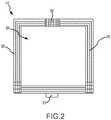
- housing 58may be substantially square in shape and may have a central aperture 64 through which the field of view from emitter 26 to detector 28 may extend.
- Field generators 60generate one or more magnetic fields.
- Field generators 60may be disposed within housing 58 and spaced apart from one another. Each generator may have three orthogonally arranged coils, arranged to create magnetic fields within an area including body 16 and to control the strength, orientation, and frequency of the fields. Magnetic fields are generated by the coils and current or voltage measurements for one or more position sensors 46, 48, 50, 52, 54 are obtained. The measured currents or voltages are proportional to the distance of the sensors 46, 48, 50, 52, 54 from the coils thereby allowing determination of a position of the sensors 46, 48, 50, 52, 54 within coordinate system 42.
- Interface 62provides a means for connecting assembly 44 to ECU 56.
- interface 62provides an electromechanical connection point to connect cables and other conductors external to assembly 44 (such as those extending between assembly 44 and ECU 56) with conductors internal to housing 58 (such as those extending between interface 62 and field generators 60).
- one or more printed circuit boards 66 having conductive tracesfurnish the conductors internal to housing 58 and the printed circuit board 66 is relatively thin, having conductors with a thickness (e.g., 0.1 millimeter) such that board 66 is translucent and therefore will minimize potential interference with imaging system 10.
- Position sensors 46, 48, 50, 52, 54provide a means for generating information regarding the position of various objects within coordinate system 42. As sensors 46, 48, 50, 52, 54 move within the magnetic field generated by generator assembly 44, the current output of each sensor 46, 48, 50, 52, 54 changes thereby indicating the location of sensors 46, 48, 50, 52, 54 within the magnetic field and within coordinate system 42. Position sensors 46, 48, 50, 52, 54 may comprise coils. Sensor 46, for example, may be wound about device 14 at or near distal end of device 14, embedded within a wall of device 14 or within a cavity within device 14.
- Sensors 46, 48, 50, 52, 54may also have appropriate insulation and/or shielding (e.g., a conductive foil or wire mesh) to cancel potential interferences from other devices near body 16.
- sensors 46, 48, 50, 52, 54may comprise any position sensors for detecting changes in magnetic fields including, for example, Hall effect sensors, magnetoresistive sensors and sensors made from magnetoresistive materials and piezoelectric materials and the like.
- Sensors 46, 48, 50, 52, 54may also be of a type that is able to sense position in one or more (e.g. 1 to 6) degrees of freedom relative to a field generator.
- Sensors 46, 48, 50, 52, 54may communicate position signals to ECU 56 through an interface (not shown) using wires or other conductors or wirelessly.
- position sensors 48, 50provides a means for generating information regarding the position of imaging system 10 within coordinate system 42.
- Position sensors 48, 50are affixed to components of imaging system 10.
- sensor 48is configured to be affixed to radiation detector 28 while sensor 50 is configured to be affixed to a component of imaging system 10 other than detector 28.
- Sensor 50may, for example, be affixed to any of support 22, arm 24 or radiation emitter 26 and is affixed to emitter 26 in the illustrated embodiment.
- Signals generated by sensor 48are indicative of the position of radiation detector 28 within coordinate system 42, but also can be used to determine the position of detector 28 relative to other components of imaging system 10 including, for example, the distance between emitter 26 and detector 28.
- Signals generated by sensor 50are indicative of the position of the component to which sensor 50 is attached within coordinate system 42 and, in particular, the angle orientation of arm 24, emitter 26 and detector 28.
- information regarding the position of imaging system 10may be generated other than through sensors 48, 50.
- one or more motion sensors 68, 70, 72may generate signals indicative of the movement of one component of imaging system 10 relative to either a prior position of the component or relative to another component of imaging system 10.
- Motion sensors 68, 70, 72may, for example, comprise accelerometers, inclinometers or gyroscopes that provide an indication of the change in position of imaging system 10.
- sensors 68, 70, 72may comprise, for example, infrared or ultrasound sensors or linear or rotary variable differential transformers that provide an indication of the change in position of imaging system 10 relative to another component of imaging system 10 or another frame of reference.
- motion sensor 68may generate a signal indicative of the degree of rotation of arm 24 relative to support 22.
- Motion sensor70may generate a signal indicative of the degree of separation between pedal 74 and a base 76 in control pedal 30.
- motion sensor 70may comprise a pressure switch indicative of force applied to pedal 74.
- Motion sensor 72may generate a signal indicative of the distance between imaging system 10 and table 20. Sensors 68, 70, 72 therefore provide an indication of the position of imaging system 10 or a component thereof.
- information regarding the position of imaging system 10may be obtained based on inputs to or outputs from the imaging system 10.
- image data output to display 32 or another destinationmay be captured and read by ECU 56 and the position of imaging system 10 determined based on fiducial markers in the image or through use of optical character recognition or other techniques for reading character data imprinted on the image and indicative of the position of imaging system 10.
- other information associated with the imagesmay be obtained from the image data. This information may include, for example, a time associated with an image such as a start time, stop time or a frame rate for the image.
- the informationmay also include an operating mode or the value of an operating parameter (e.g., the amount of radiation generated or a magnification (or zoom) level) for imaging system 10.
- control data input to imaging system 10may be captured and read by ECU and used to determine the position of imaging system 10 and/or other information associated with imaging system 10.
- an actuation command generated by control pedal 30may be captured and read by ECU 56 and used to identify the imaging system control (in the case of multiple control inputs) and to determine the beginning and end times of image capture.
- An output signal from imaging system 10 to a facility's warning light indicative of radiation emissionmay also be captured and read by ECU 56 and used to determine the beginning and end time of image capture.
- information regarding the position of imaging system 10 and/or other information associated imaging system 10may be obtained by sensing the activation of imaging system 10 and, in particular, the existence of radiation from emitter 26. Radiation emissions may be detected using a radiation detection sensor such as the XB8816 Series sensor offered for sale by X-Scan Imaging Corporation. ECU 56 may be configured to determine a time associate with the radiation emission responsive to a signal generated by the radiation detector sensor and thereby synchronize signals generated by other sensors such as position sensors 46, 48, 50, 52, 54.
- information regarding the position of imaging system 10may be obtained by detecting objects, such as anatomical or artificial fiducials, in images generated by system 10 that have a known position within coordinate system 42.
- objectssuch as anatomical or artificial fiducials
- these objectsmay have multiple states whereby the objects are visible in some images and invisible in others or may be generally undetectable to the human eye, but detectable through image processing as described in greater detail in PCT International Publication No. WO 2012/090148 A1 , the entire disclosure of which is incorporated herein by reference.
- a position monitoring device 78may be positioned remote from imaging system 10 and detect movement of imaging system 10.
- Device 78may, for example, comprise a video camera. Images from the camera may be processed by ECU 56 to determine changes in position of imaging system 10.
- Device 78may alternatively comprise an ultrasound transducer that generates ultrasonic waves towards imaging system and detects reflection of such waves as an indication of position or an infrared or other optic based sensor that detects reflection of light waves generated by a light emitter.
- Imaging system 10may include one or more reflectors 80, 82 or similar devices intended to reflect waves generated by device 78 or another emitter.
- a system for navigating a medical device 14may include magnetic field generator assembly 44, a position monitoring device 78 remote from imaging system 10, first and second position reference elements such as reflectors 80, 82 or emitters (depending on the composition of position monitoring device 78) and an ECU 56 with at least one of the position reference elements affixed to imaging system 10 and wherein one of assembly 44 or the position reference elements is correlated to a position of emitter 26, another of assembly 44 or the position reference elements is correlated to a position of detector 28 and yet another of assembly 44 or the position reference elements is correlated to a position of body 16, and ECU 56 is configured to determine, responsive to signals received from position sensor 46 on device 14 and device 78, a position of device 14 and a position of emitter 26 or detector 28 within coordinate system 42 and a distance between emitter 26 and detector 28.
- first and second position reference elementssuch as reflectors 80, 82 or emitters (depending on the composition of position monitoring device 78)
- an ECU 56with at least one of the position reference elements
- information about the position of the imaging system 10could be obtained using position sensors 48, 50 and motion sensor 68 (e.g., ECU 56 could separately determine the position of imaging system 10 in response to each sensor and average the values to reduce error).
- ECU 56provides a means for determining the position of sensors 46, 48, 50, 52, 54--and the objects to which sensors 46, 48, 50, 52, 54 are attachedwithin coordinate system 42. As discussed below, ECU 56 may further provides a means for registering images generated by imaging system 10 in coordinate system 42 and superimposing images of device 14 on such images, a means for comparing the positions of various objects in the EP lab (such as imaging system 10 and generator assembly 44 or body 16 or table 20) to determine potential interference, and/or a means for providing information about the positions of various objects to a physician or other user of system 12. ECU 56 also provides a means for controlling the operation of various components of system 12 including magnetic field generator assembly 44.
- ECU 56may also provide a means for controlling device 14 and for determining the geometry of heart 18, electrophysiology characteristics of heart 18 and the position and orientation of device 14 relative to heart 18 and body 16.
- ECU 56may also provide a means for generating display signals used to control a display such as display 32.
- ECU 56may comprise one or more programmable microprocessors or microcontrollers or may comprise one or more application specific integrated circuits (ASICs).
- ASICsapplication specific integrated circuits
- ECU 56may include a central processing unit (CPU) and an input/output (I/O) interface through which ECU 56 may receive a plurality of input signals including signals generated by sensors 46, 48, 50, 52, 54, and generate a plurality of output signals including those used to control and/or provide data to magnetic field generator assembly 44 and display 32.
- CPUcentral processing unit
- I/Oinput/output
- ECU 56may be configured with programming instructions from a computer program (i.e., software) to implement a method for navigating a medical device 14 within body 16.
- the programmay be stored in a computer storage medium such as a memory (not shown) that is internal to ECU 56 or external to ECU 56 and may be pre-installed in the memory or obtained from a computer storage medium external to ECU 56 including from various types of portable media (e.g., compact discs, flash drives, etc.) or file servers or other computing devices accessible through a telecommunications network.
- an exemplary method for navigating a medical device 14 within body 16may begin with the step 84 of generating one or more magnetic fields with a magnetic field generator assembly 44 disposed outside of body 16.
- ECU 56may generate control signals to magnetic field generator assembly 44 causing generation of the magnetic fields.
- the methodmay continue with the step 86 of receiving position signals from one or more of position sensors 46, 48, 50, 52, 54 responsive to the location of sensors 46, 48, 50, 52, 54 within the magnetic fields.
- the methodmay continue with the step 88 of determining, responsive to the signals from one or more of sensors 46, 48, 50, 52, 54, the positions of various objects in the electrophysiology lab and within coordinate system 42 and related information.
- step 88may include the substeps 90, 92, 94 of determining the position of medical device 14, determining the position of at least one of emitter 26 and detector 28 and determining a distance between emitter 26 and detector 28.
- ECU 56may determine the positions, in part, by comparing the current value of position signals to a reference value indicative of the origin of coordinate system 56.
- ECU 56may determine the position of emitter 26 and/or detector 28 and the distance between emitter 26 and detector 28 using vector-calculus when sensors 48, 50 comprise six degree of freedom sensors because sensors 48, 50 are attached to rigid bodies in detector 28 and emitter 26, respectively.
- ECU 56can use neural network algorithms to learn to generate accurate outputs of the position of emitter 26 and/or detector 28 and the distance between emitter 26 and detector 28 responsive to inputs from a group of sensors (e.g., 48, 50, and 54). ECU 56 may be configured to determine the positions despite variation in the position of generator assembly 44 and using various combinations of sensors 48, 50, 52. To account for the various degrees of freedom within the illustrated electrophysiology lab, one of assembly 44 and sensors 48, 50, 52 may be correlated to a position of emitter 26, another of assembly 44 and sensors 48, 50, 52 may be correlated to a position of detector 28 and yet another of assembly 44 and sensors 48, 50, 52 may be correlated to a position of body 16.
- assembly 44may be correlated to body 16 by virtue of the attachment of assembly 44 and body 16 to table 20, sensor 48 may be correlated to detector 28 and sensor 50 may be correlated to emitter 26.
- assembly 44may be attached, for example, to detector 28 and be correlated with detector 28, while sensor 50 may be correlated to emitter 26 and sensor 52 may be correlated to body 16.
- ECU 56may be further configured to perform various functions. For example, in one embodiment, ECU 56 may be configured to perform the step 96 of registering an image generated by imaging system 10 in coordinate system 42. Step 96 may include the substep of determining the angle or orientation of arm 24, emitter 26 and/or detector 28. ECU 56 can determine the angle or orientation of arm 24, emitter 26 and/or detector 28 responsive to the position signal generated by sensor 50. Using the angle of orientation and the distance between emitter 26 and detector 28, ECU 56 can register image within coordinate system 42. ECU 56 may further be configured to determine the coordinates in coordinate system 42 of individual pixels within the image.
- ECU 56may further be configured to perform the step 98 of superimposing an image of device 14 on the image responsive to the position signal generated by sensor 46.
- ECU 56may generate an icon or similar representation of device 14 at a position on the image responsive to the determined coordinates of sensor 46.
- ECU 56may be configured to perform the step 100 of displaying positions of one or more of the detector 28 or other imaging system components on a display such as display 32.
- Basic position informationmay be represented numerically or graphically to the physician by ECU 56 on display 32 and may be useful to the physician in to, for example, evaluate the impact of positioning commands on imaging system 10.
- ECU 56may be configured to perform the step 102 of comparing the position of radiation detector 28 or another component of imaging system 10 with the position of other objects in the EP lab. For example, ECU 56 may compare the position of detector 28 or another component of imaging system 10 with the known location of magnetic field generator assembly 44. In this manner, ECU 56 can determine whether the current position (or a potential change in position) will cause contact or other physical interference between imaging system 10 and assembly 44. ECU 56 can also determine whether the current position (or a potential change in position) will cause the imaging system to distort or otherwise interfere with the magnetic fields generated by assembly 44. ECU 56 can also determine whether the relative positions of imaging system 10 and assembly 44 will interfere with the acquisition of images by imaging system 10 or otherwise decrease the quality of such images.
- ECU 56may also compare the position of detector 28 or another component of imaging system 10 with a position of body 16 and/or table 20.
- ECU 56may be configured to determine the position or a change in position of body 16 or table 20 responsive to position signals generated by position sensors 52, 54 affixed to body 16 and table 20.
- ECU 56may then compare the position of body 16 and/or table 20 with that of detector 28 or another component of imaging system 10.
- ECU 56may use this information to insure a desired alignment between imaging system 10 and body 16 and/or table 20 and/or to prevent physical contact between imaging system 10 and body 16 and/or table 20.
- ECU 56can halt image acquisition by imaging system 10, generate a warning to the physician (e.g., an audible noise or a visual warning on display 32) and/or generate a command resulting in movement of imaging system 10 to realign system 10 with body 16 or table 20.
- a warning to the physiciane.g., an audible noise or a visual warning on display 32
- a command resulting in movement of imaging system 10to realign system 10 with body 16 or table 20.
- ECU 56determines that body 16 and/or table 20 is less than a threshold distance from imaging system 10
- ECU 56can issue a warning to the physician (e.g. an audible noise, or a visual warning on display 32) or issue a command resulting in movement of imaging system 10 away from body 16 and/or table 20.
- ECU 56may also act to prevent further commanded movements of imaging system 10 in order to prevent imaging system 10 from contacting body 16 and/or table 20 or falling below a threshold distance between imaging system 10 and body 16 and/or table 20.
- the systemmay eliminate or reduce the reliance on mechanical collision detection devices such as microswitches that may create magnetic interference.
- the threshold distancemay comprise a border of a volume (e.g., a box) surrounding the body 16 and/or table 20.
- the volumemay, in some embodiments, be calibrated to the table 20 or particular body 16 of a given patient through pre-procedure movement of sensors 52 and/or 54 to contact various points on the body 16 and/or table 20, respectively, and use of a graphical user interface for the physician to establish the volume.
- a plurality of sensors 52, 54 disposed on body 16 and/or table 20, respectively,could be used to establish the volume.
- an imaging systemsuch as imaging system 10 may include an imaging system anti-collision feature.
- an imaging system anti-collision featuremay be employed to prevent or minimize collision or otherwise undesirable contact between one or more imaging system components and other items in the EP lab, such as for example, body 16, table 20, and/or magnetic field generator assembly 44. Details regarding such an anti-collision feature or features may be found in one or more of the following patents: United States patent no. 5,828,221 (issued 27 October 1998 ), United States patent no. 6,408,051 (issued 18 June 2002 ), United States patent no. 8,269,176 (issued 18 September 2012 ), United States patent no. 4,593,189 (issued 3 June 1986 ), United States patent no.
- anti-collision featuresinclude those branded as "SafeMove” available with imaging systems from Siemens AG and "BodyGuard” available with imaging systems from Koninklijke Philips N.V.
- the anti-collision featuremay comprise, for example, force, proximity, and/or capacitive sensors 104. Sensors 104 generate a signal indicative of the distance between components of imaging system 10 and other items in the EP lab, such as for example, body 16, table 20, and/or magnetic field generator assembly 44.
- the signalcan indicate be indicative of the absolute distance or indicate that the distance has fallen below a threshold value.
- Sensors 104can transmit signals via a wired or wireless connection to a control unit such as ECU 56 or a dedicated control unit (not shown) for movement of imaging system 10.
- the control unitgenerates control signals responsive the signals from sensors 104 to control one or more motors 106 and/or brakes or clutches 108 used in controlling the movement of imaging system along and about axes 34, 36, 38, 40.
- control unitmay, in response to signals generated by sensors 104, deactivate the motors 106 causing motion of the imaging system components and/or direct brakes 108 to apply mechanical braking force to the same to prevent or inhibit further contact from a component of an imaging system, e.g., system 10, with a patient's body or a patient table, e.g., body 16 or table 20.
- imaging systemsmay include a programmed, predefined spatial envelope of a table's physical dimensions and initial starting position and include the ability to track the table's movement, such that the system may avoid collisions or other undesirable contact by preventing components of the imaging system, such as system 10, from moving undesirably into unnecessary contact with a defined, known object, such as table 20.
- a medical device navigation systemsuch as navigation system 12 may be configured such that an anti-collision feature of an imaging system, such as imaging system 10 is employed to prevent or minimize undesirable contact between components of the imaging system 10 and components of the navigation system 12.
- the navigation system 12may be configured to passively and/or actively cause an anti-collision feature of imaging system 10 to engage. Focusing now on such passive techniques, in various embodiments, one or more components of navigation system 12 may be configured to emulate a patient body 16 or table 20 in such a way that the imaging system 10 does not collide with components of navigation system 12 because the internal anti-collision feature of the imaging system 10 may be activated.
- a table-mounted magnetic field generator assemblysuch as assembly 44 seen, for example, in Figures 1 , 5 , and 6 and 8 , may include a capacitive property that could be detected by the capacitive detector of the imaging system 10.
- the generator assembly 44may include a conductive material that may be detected by a capacitive detector of an imaging system.
- at least part of the magnetic field generator assembly 44may be built from a conductive material, such as carbon fibers that may also be used in table 20. Additionally or alternatively, at least part of the generator assembly 44 may be painted with a conductive paint and/or covered with a conductive cover, such as a bag or wrap made of a conductive cloth.
- navigation system 12may be configured to actively cause an anti-collision feature to activate.
- ECU 56may be configured to send a signal or appropriate electromagnetic wave to imaging system 10 to engage an anti-collision feature such as that described above.
- positions and dimensions of the applicable components of the imaging system 10e.g., the emitter 26 and detector 28
- the applicable components of navigation system 12e.g., the generator assembly 44
- ECU 56may be accounted for by ECU 56, as discussed above in relation to step 102 (see Figure 7 ).
- ECU 56may cause imaging system 10 to engage an anti-collision feature and/or generate a warning to the physician or other operator of imaging system 10 and/or navigation system 12.
- an interfacesuch as a TCP/IP communication between the imaging system 10 and navigation system 12 may be used to send a relevant message therebetween based on an agreed protocol between the systems.
- navigation system 12 and/or imaging system 10may include one or more designated parts (not shown) that may activate an anti-collision feature by being actuated remotely by ECU 56.
- a designated partmay be configured to push on a force sensor and/or other mechanical anti-collision detector of the imaging system 10.
- Such a designated partmay be installed close to each force sensor(s) 104 in the emitter 26 and detector 28 of imaging system 10.
- joinder referencesdo not necessarily infer that two elements are directly connected and in fixed relation to each other. It is intended that all matter contained in the above description or shown in the accompanying drawings shall be interpreted as illustrative only and not as limiting. Changes in detail or structure may be made without departing from the present teachings as defined in the appended claims.
Landscapes
- Health & Medical Sciences (AREA)
- Life Sciences & Earth Sciences (AREA)
- Engineering & Computer Science (AREA)
- Medical Informatics (AREA)
- Surgery (AREA)
- General Health & Medical Sciences (AREA)
- Veterinary Medicine (AREA)
- Molecular Biology (AREA)
- Public Health (AREA)
- Animal Behavior & Ethology (AREA)
- Biomedical Technology (AREA)
- Heart & Thoracic Surgery (AREA)
- Nuclear Medicine, Radiotherapy & Molecular Imaging (AREA)
- Physics & Mathematics (AREA)
- Pathology (AREA)
- Biophysics (AREA)
- Radiology & Medical Imaging (AREA)
- Optics & Photonics (AREA)
- High Energy & Nuclear Physics (AREA)
- Human Computer Interaction (AREA)
- Cardiology (AREA)
- Plasma & Fusion (AREA)
- Otolaryngology (AREA)
- Robotics (AREA)
- Gynecology & Obstetrics (AREA)
- Oral & Maxillofacial Surgery (AREA)
- Computer Vision & Pattern Recognition (AREA)
- Apparatus For Radiation Diagnosis (AREA)
- Magnetic Resonance Imaging Apparatus (AREA)
- Ultra Sonic Daignosis Equipment (AREA)
- Measurement And Recording Of Electrical Phenomena And Electrical Characteristics Of The Living Body (AREA)
- Surgical Instruments (AREA)
- Endoscopes (AREA)
Description
- The present disclosure relates to a system for navigating a medical device within a body. In particular, the instant disclosure relates to a medical device navigation system configured to obtain information from and/or interact with a medical imaging system when the medical imaging system is not integrated with the medical device navigation system.
US 2008/0118103 A1 relates to a system for navigating an image-guided object through an imaged subject supported on table in relation to an image acquired by an image detector is provided. The system includes a first tracking element attached to the patient, and a second tracking element attached at the table. The first and second tracking elements define first and second coordinate systems. A controller is operable to register the second coordinate system with a third coordinate system defined by the image detector, measure a spatial relation between the first tracking element and the second tracking element, register the first coordinate system with the third local coordinate system defined by the image detector based on the spatial relation between the first and second tracking elements, and generating a composite image comprising a virtual image of the object in spatial relation to the image of the imaged subject acquired by the image detector.US 2008/0125997 A1 relates to tracking systems that use magnetic fields such as for surgical interventions and other medical procedures.WO 2005/013828 A1 relates to an imaging system that includes a source and a detector that can be moved out of the way after scanning. During scanning, the actual paths that the source and detector travel are tracked, such as by an associated surgical navigation system tracking system. The actual locations of the source and detector during each x-ray image are used in the image reconstruction algorithm.US 2012/0230473 A1 relates to an apparatus for radiation imaging and to a positioning apparatus for providing proper alignment of the radiation source relative to an image detection device for recording a radiation image.- A wide variety of medical devices are inserted into the body to diagnose and treat various medical conditions. Catheters, for example, are used to perform a variety of tasks within human bodies and other bodies including the delivery of medicine and fluids, the removal of bodily fluids and the transport of surgical tools and instruments. In the diagnosis and treatment of atrial fibrillation, for example, catheters may be used to deliver electrodes to the heart for electrophysiological mapping of the surface of the heart and to deliver ablative energy to the surface among other tasks. Catheters are typically routed to a region of interest through the body's vascular system. In a conventional approach, an introducer is used to puncture the skin surface and a sheath having an inner diameter greater than the outer diameter of the catheter is threaded through the vasculature to a region of interest. The catheter is then moved longitudinally through the sheath to the region of interest either manually by a clinician or through the use of electromechanical drive systems.
- It is desirable to track the position of medical devices such as catheters as they are moved within the body so that, for example, drugs and other forms of treatment are administered at the proper location and medical procedures can be completed more efficiently and safely. One conventional means to track the position of medical devices within the body is fluoroscopic imaging. Fluoroscopy is disadvantageous, however, because it subjects the patient and physician to undesirable levels of electromagnetic radiation. As a result, medical device navigation systems have been developed to track the position of medical devices within the body. These systems typically rely on the generation of electrical or magnetic fields and the detection of induced voltages and currents on position sensors attached to the medical device and/or external to the body. The information derived from these systems is then provided to a physician through, for example, a visual display. Oftentimes, a representation of the medical device is displayed relative to a computer model or one or more images (including, but not limited to, fluoroscopic images) of the anatomical region in which the device is being maneuvered. In order to display the medical device at the correct location relative to the model or image, the model or image must be registered within the coordinate system of the navigation system.
- Images may be registered in the coordinate system of a medical device navigation system in a variety of ways. If the imaging system used to capture the images is physically integrated with the navigation system, as described in commonly assigned
U.S. Published Patent Application No. 2008/0183071 , the imaging system can be registered with the navigation system during installation and the spatial relationship of the navigation system to the imaging system is thereafter constant and known, obviating the need for registration during each new procedure. Where the navigation system and imaging system are physically separate, however, the changing spatial relationship of the systems makes registration more complicated. Further, even when the navigation system and imaging system are physically integrated, the initial registration process is relatively time consuming. - The foregoing discussion is intended only to illustrate the present field and should not be taken as a disavowal of claim scope.
- The present invention is defined by appended claim 1. Specific embodiments are set forth in the dependent claims.
- The foregoing and other aspects, features, details, utilities, and advantages of the present disclosure will be apparent from reading the following description and claims, and from reviewing the accompanying drawings.
Figure 1 is a diagrammatic view of a medical device navigation system in accordance with one embodiment of the invention.Figure 2 is a diagrammatic view of a magnetic field generator assembly of the system ofFigure 1 .Figure 3 is a diagrammatic view of a medical device navigation system in accordance with another embodiment of the present invention.Figure 4 is a diagrammatic view of a medical device navigation system in accordance with another embodiment of the present invention.Figure 5 is a diagrammatic view of a medical device navigation system in accordance with another embodiment of the present invention.Figure 6 is a diagrammatic view of a medical device navigation system in accordance with another example.Figure 7 is a flow chart diagram illustrating methods for navigating a medical device.Figure 8 is a diagrammatic view of a medical device navigation system in accordance with another example.- Various embodiments are described herein to various apparatuses, systems, and/or methods. Numerous specific details are set forth to provide a thorough understanding of the overall structure, function, manufacture, and use of the embodiments as described in the specification and illustrated in the accompanying drawings. It will be understood by those skilled in the art, however, that the embodiments may be practiced without such specific details. In other instances, well-known operations, components, and elements have not been described in detail so as not to obscure the embodiments described in the specification. Those of ordinary skill in the art will understand that the embodiments described and illustrated herein are nonlimiting examples, and thus it can be appreciated that the specific structural and functional details disclosed herein may be representative and do not necessarily limit the scope of the embodiments, the scope of which is defined solely by the appended claims.
- Reference throughout the specification to "various embodiments," "some embodiments," "one embodiment," or "an embodiment", or the like, means that a particular feature, structure, or characteristic described in connection with the embodiment is included in at least one embodiment. Thus, appearances of the phrases "in various embodiments," "in some embodiments," "in one embodiment," or "in an embodiment", or the like, in places throughout the specification are not necessarily all referring to the same embodiment. Furthermore, the particular features, structures, or characteristics may be combined in any suitable manner in one or more embodiments. Thus, the particular features, structures, or characteristics illustrated or described in connection with one embodiment may be combined, in whole or in part, with the features, structures, or characteristics of one or more other embodiments without limitation given that such combination is not illogical or non-functional.
- It will be appreciated that the terms "proximal" and "distal" may be used throughout the specification with reference to a clinician manipulating one end of an instrument used to treat a patient. The term "proximal" refers to the portion of the instrument closest to the clinician and the term "distal" refers to the portion located furthest from the clinician. It will be further appreciated that for conciseness and clarity, spatial terms such as "vertical," "horizontal," "up," and "down" may be used herein with respect to the illustrated embodiments. However, surgical instruments may be used in many orientations and positions, and these terms are not intended to be limiting and absolute.
- Referring now to the drawings wherein like reference numerals are used to identify identical components in the various views,
Figure 1 illustrates an electrophysiology lab including animaging system 10 and asystem 12 for navigating amedical device 14 relative to and within a region of interest in abody 16 such as theheart 18 in accordance with one embodiment of the present teachings.Device 14 may comprise, for example, an electrophysiological (EP) mapping catheter, an intracardiac echocardiography (ICE) catheter or an ablation catheter used to diagnose and treat cardiac tissue. It should be understood, however, that the inventive system could be used to navigate a variety of diagnostic and treatment devices used to treat various regions of interest withinbody 16. Imaging system 10 is provided to acquire images ofheart 18 or another anatomical regions of interest and comprises a fluoroscopic imaging system in the illustrated embodiment.System 10 has a structure that is movable relative to the various components ofsystem 12 and relative tobody 16 and a table 20 supportingbody 16.System 10 may include a number of structural components including, in the illustrated embodiment, asupport 22, anarm 24, aradiation emitter 26 and aradiation detector 28.System 10 may also include an electronic control unit (not shown) for controlling operation ofsystem 10 and one or more input devices such ascontrol pedal 30 and output devices such asdisplay 32.Support 22 provides a means for supportingarm 24 and for movingarm 24,emitter 26 anddetector 28 relative tobody 16. In the illustrated embodiment,support 22 is suspended from a ceiling in the EP lab.Support 22 may be affixed to rails (not shown) or similar structures and may be moved by mechanical, electrical, or electromechanical devices (not shown).Support 22 may be configured to rotate witharm 24,emitter 26 anddetector 28 about anaxis 34 to positionarm 24,emitter 26 anddetector 28 relative tobody 16.Arm 24 provides a means for supportingemitter 26 anddetector 28 relative tobody 16.Arm 24 may be substantially C-shaped (i.e., a "C-arm") to provide sufficient clearance relative tobody 16 and table 20.Arm 24 is configured to rotate in either direction about anaxis 36 relative to support 22 to cause corresponding movement ofemitter 26 anddetector 28 andposition emitter 26 anddetector 28 relative tobody 16 to permit images to be acquired from a variety of angles or orientations.Emitter 26 is provided to emit electromagnetic radiation (e.g., X-rays) over a field of view betweenemitter 26 anddetector 28 including the anatomical region of interest inbody 16.Emitter 26 is disposed at one end ofarm 24.Detector 28 captures electromagnetic radiation passing through the anatomical region of interest inbody 16 and generates signals used to create images of the region of interest. In one embodiment,detector 28 may comprise a flat detector and may be configured to rotate about anaxis 38 relative toarm 24 and may also be movable relative toarm 24 along anaxis 40 to vary the distance between theemitter 26 and detector 28 (i.e. the "source to image" distance or "SID").Detector 28 is disposed at an opposite end ofarm 24 relative toemitter 26.- The relative movement of
imaging system 10 and other objects within the electrophysiology lab create various degrees of freedom thatsystem 12 may need to account for when navigatingdevice 14. In addition to rotation aboutaxes axes 40, table 20 may move relative to imaging system 10 (or vice versa) in either direction along three orthogonal axes resulting in as many as seven degrees of freedom. Control pedal 30 provides a means for the physician to controlimaging system 12. The physician may, for example, depresspedal 30 to activateradiation emitter 26.Pedal 30 may communicate with an electronic control unit (not shown) forimaging system 12 via a wired or wireless connection.Display 32 is provided to convey information to a physician to assist in diagnosis and treatment.Display 32 may comprise one or more computer monitors or other display devices.Display 32 may present a graphical user interface (GUI) to the physician. The GUI may include a variety of information including, for example, an image of the geometry ofheart 18, electrophysiology data associated with theheart 18, graphs illustrating voltage levels over time for various electrodes onmedical device 14, and images ofmedical device 14 and related information indicative of the position ofdevice 14 and other devices relative to theheart 18.System 12 may be used to determine the position ofdevice 14 withinbody 16 and within a coordinatesystem 42 and to navigatedevice 14 withinbody 16.System 12 may also be used to determine the positions of other movable objects within the EP lab within coordinatesystem 42 includingbody 16 and table 20. In accordance with one embodiment of the present teachings,system 12 is also used to determine the position ofimaging system 10 within coordinatesystem 42 and, in particular, various components ofimaging system 10.System 12 employs magnetic fields and may comprise the system made available under the trademark MediGuide™ by St. Jude Medical, Inc. and generally shown and described in, for example,U.S. Patent No. 7,386,339 .System 12 may include a magneticfield generator assembly 44, means, such asposition sensors device 14 withinbody 16 and the position of various objects in the EP lab such asimaging system 10,body 16 and table 20.System 12 may also include an electronic control unit (ECU) 56 and a display such asdisplay 32.Generator assembly 44 generates magnetic fields that cause a response insensors sensors system 42. Referring toFigure 2 ,generator assembly 44 may include ahousing 58, a plurality offield generators 60, and acontrol interface 62.Housing 58 provides structural support to other components ofassembly 44 includingfield generators 60, associated conductors, and possibly control and signal processing circuitry and protects these components from foreign objects and elements. In certain embodiments,housing 58 may be mounted to a component ofimaging system 10 such asarm 24,emitter 26 ordetector 28. Referring toFigures 3 and4 , for example,assembly 44 may be mounted todetector 28 and to emitter 26 in certain embodiments. Referring again toFigure 1 , in accordance with one embodiment,housing 58 is not directly coupled to, or integrated with,imaging system 10. As a result,generator assembly 44 may be used with various imaging systems, but is not co-registered withimaging system 10. In accordance with one embodiment,housing 58 may be disposed underneath table 20 andbody 16 and may be configured to be attached to table 20. Referring again toFigure 2 ,housing 58 may be substantially square in shape and may have acentral aperture 64 through which the field of view fromemitter 26 todetector 28 may extend.Field generators 60 generate one or more magnetic fields.Field generators 60 may be disposed withinhousing 58 and spaced apart from one another. Each generator may have three orthogonally arranged coils, arranged to create magnetic fields within anarea including body 16 and to control the strength, orientation, and frequency of the fields. Magnetic fields are generated by the coils and current or voltage measurements for one ormore position sensors sensors sensors system 42.Interface 62 provides a means for connectingassembly 44 toECU 56. In particular,interface 62 provides an electromechanical connection point to connect cables and other conductors external to assembly 44 (such as those extending betweenassembly 44 and ECU 56) with conductors internal to housing 58 (such as those extending betweeninterface 62 and field generators 60). In accordance with one aspect of the present teachings, one or more printedcircuit boards 66 having conductive traces furnish the conductors internal tohousing 58 and the printedcircuit board 66 is relatively thin, having conductors with a thickness (e.g., 0.1 millimeter) such thatboard 66 is translucent and therefore will minimize potential interference withimaging system 10.Position sensors system 42. Assensors generator assembly 44, the current output of eachsensor sensors system 42.Position sensors Sensor 46, for example, may be wound aboutdevice 14 at or near distal end ofdevice 14, embedded within a wall ofdevice 14 or within a cavity withindevice 14.Sensors body 16. In alternative embodiments,sensors Sensors Sensors ECU 56 through an interface (not shown) using wires or other conductors or wirelessly.- In accordance with one embodiment of the present teachings,
position sensors imaging system 10 within coordinatesystem 42.Position sensors imaging system 10. In the illustrated embodiment,sensor 48 is configured to be affixed toradiation detector 28 whilesensor 50 is configured to be affixed to a component ofimaging system 10 other thandetector 28.Sensor 50 may, for example, be affixed to any ofsupport 22,arm 24 orradiation emitter 26 and is affixed toemitter 26 in the illustrated embodiment. Signals generated bysensor 48 are indicative of the position ofradiation detector 28 within coordinatesystem 42, but also can be used to determine the position ofdetector 28 relative to other components ofimaging system 10 including, for example, the distance betweenemitter 26 anddetector 28. Signals generated bysensor 50 are indicative of the position of the component to whichsensor 50 is attached within coordinatesystem 42 and, in particular, the angle orientation ofarm 24,emitter 26 anddetector 28. - In accordance with other embodiments of the present teachings, information regarding the position of
imaging system 10 may be generated other than throughsensors Figure 5 , in another embodiment one ormore motion sensors imaging system 10 relative to either a prior position of the component or relative to another component ofimaging system 10.Motion sensors imaging system 10. Alternativelysensors imaging system 10 relative to another component ofimaging system 10 or another frame of reference. In the illustrated embodiment, for example,motion sensor 68 may generate a signal indicative of the degree of rotation ofarm 24 relative to support 22. Motion sensor70 may generate a signal indicative of the degree of separation between pedal 74 and a base 76 incontrol pedal 30. Alternatively,motion sensor 70 may comprise a pressure switch indicative of force applied to pedal 74.Motion sensor 72 may generate a signal indicative of the distance betweenimaging system 10 and table 20.Sensors imaging system 10 or a component thereof. - In accordance with another embodiment of the present teachings, information regarding the position of
imaging system 10 may be obtained based on inputs to or outputs from theimaging system 10. In one embodiment, image data output to display 32 or another destination may be captured and read byECU 56 and the position ofimaging system 10 determined based on fiducial markers in the image or through use of optical character recognition or other techniques for reading character data imprinted on the image and indicative of the position ofimaging system 10. In addition to the position ofimaging system 10, other information associated with the images may be obtained from the image data. This information may include, for example, a time associated with an image such as a start time, stop time or a frame rate for the image. The information may also include an operating mode or the value of an operating parameter (e.g., the amount of radiation generated or a magnification (or zoom) level) forimaging system 10. In other embodiments, control data input toimaging system 10 may be captured and read by ECU and used to determine the position ofimaging system 10 and/or other information associated withimaging system 10. For example, an actuation command generated bycontrol pedal 30 may be captured and read byECU 56 and used to identify the imaging system control (in the case of multiple control inputs) and to determine the beginning and end times of image capture. An output signal fromimaging system 10 to a facility's warning light indicative of radiation emission may also be captured and read byECU 56 and used to determine the beginning and end time of image capture. - In accordance with yet another embodiment of the present teachings, information regarding the position of
imaging system 10 and/or other information associatedimaging system 10 may be obtained by sensing the activation ofimaging system 10 and, in particular, the existence of radiation fromemitter 26. Radiation emissions may be detected using a radiation detection sensor such as the XB8816 Series sensor offered for sale by X-Scan Imaging Corporation.ECU 56 may be configured to determine a time associate with the radiation emission responsive to a signal generated by the radiation detector sensor and thereby synchronize signals generated by other sensors such asposition sensors - In accordance with yet another embodiment of the present teachings, information regarding the position of
imaging system 10 may be obtained by detecting objects, such as anatomical or artificial fiducials, in images generated bysystem 10 that have a known position within coordinatesystem 42. To limit interference with the physician's view of the anatomy, these objects may have multiple states whereby the objects are visible in some images and invisible in others or may be generally undetectable to the human eye, but detectable through image processing as described in greater detail inPCT International Publication No. WO 2012/090148 A1 , the entire disclosure of which is incorporated herein by reference. - In accordance with yet another embodiment of the present teachings, information regarding the position of
imaging system 10 may be obtained using sensors that remotely monitor movement ofimaging system 10. Referring toFigure 6 , aposition monitoring device 78 may be positioned remote fromimaging system 10 and detect movement ofimaging system 10.Device 78 may, for example, comprise a video camera. Images from the camera may be processed byECU 56 to determine changes in position ofimaging system 10.Device 78 may alternatively comprise an ultrasound transducer that generates ultrasonic waves towards imaging system and detects reflection of such waves as an indication of position or an infrared or other optic based sensor that detects reflection of light waves generated by a light emitter.Imaging system 10 may include one ormore reflectors device 78 or another emitter. Thus, a system for navigating amedical device 14 in accordance with one embodiment may include magneticfield generator assembly 44, aposition monitoring device 78 remote fromimaging system 10, first and second position reference elements such asreflectors ECU 56 with at least one of the position reference elements affixed toimaging system 10 and wherein one ofassembly 44 or the position reference elements is correlated to a position ofemitter 26, another ofassembly 44 or the position reference elements is correlated to a position ofdetector 28 and yet another ofassembly 44 or the position reference elements is correlated to a position ofbody 16, andECU 56 is configured to determine, responsive to signals received fromposition sensor 46 ondevice 14 anddevice 78, a position ofdevice 14 and a position ofemitter 26 ordetector 28 within coordinatesystem 42 and a distance betweenemitter 26 anddetector 28. - Although various embodiments have been disclosed above for obtaining information regarding the position of
imaging system 10, it should be understood that elements of multiple embodiments could be used in combination. As but one example, information about the position of theimaging system 10 could be obtained usingposition sensors ECU 56 could separately determine the position ofimaging system 10 in response to each sensor and average the values to reduce error). - Referring again to
Figure 1 ,ECU 56 provides a means for determining the position ofsensors sensors system 42. As discussed below,ECU 56 may further provides a means for registering images generated byimaging system 10 in coordinatesystem 42 and superimposing images ofdevice 14 on such images, a means for comparing the positions of various objects in the EP lab (such asimaging system 10 andgenerator assembly 44 orbody 16 or table 20) to determine potential interference, and/or a means for providing information about the positions of various objects to a physician or other user ofsystem 12.ECU 56 also provides a means for controlling the operation of various components ofsystem 12 including magneticfield generator assembly 44. In embodiments wheremedical device 14 comprises an electrophysiology or ablation catheter,ECU 56 may also provide a means for controllingdevice 14 and for determining the geometry ofheart 18, electrophysiology characteristics ofheart 18 and the position and orientation ofdevice 14 relative toheart 18 andbody 16.ECU 56 may also provide a means for generating display signals used to control a display such asdisplay 32.ECU 56 may comprise one or more programmable microprocessors or microcontrollers or may comprise one or more application specific integrated circuits (ASICs).ECU 56 may include a central processing unit (CPU) and an input/output (I/O) interface through whichECU 56 may receive a plurality of input signals including signals generated bysensors field generator assembly 44 anddisplay 32. - In accordance with the present teachings,
ECU 56 may be configured with programming instructions from a computer program (i.e., software) to implement a method for navigating amedical device 14 withinbody 16. The program may be stored in a computer storage medium such as a memory (not shown) that is internal toECU 56 or external toECU 56 and may be pre-installed in the memory or obtained from a computer storage medium external toECU 56 including from various types of portable media (e.g., compact discs, flash drives, etc.) or file servers or other computing devices accessible through a telecommunications network. - Referring to
Figure 7 , an exemplary method for navigating amedical device 14 withinbody 16 may begin with thestep 84 of generating one or more magnetic fields with a magneticfield generator assembly 44 disposed outside ofbody 16.ECU 56 may generate control signals to magneticfield generator assembly 44 causing generation of the magnetic fields. The method may continue with thestep 86 of receiving position signals from one or more ofposition sensors sensors step 88 of determining, responsive to the signals from one or more ofsensors system 42 and related information. In accordance with one embodiment of the present teachings, step 88 may include thesubsteps medical device 14, determining the position of at least one ofemitter 26 anddetector 28 and determining a distance betweenemitter 26 anddetector 28.ECU 56 may determine the positions, in part, by comparing the current value of position signals to a reference value indicative of the origin of coordinatesystem 56.ECU 56 may determine the position ofemitter 26 and/ordetector 28 and the distance betweenemitter 26 anddetector 28 using vector-calculus whensensors sensors detector 28 andemitter 26, respectively. Alternatively,ECU 56 can use neural network algorithms to learn to generate accurate outputs of the position ofemitter 26 and/ordetector 28 and the distance betweenemitter 26 anddetector 28 responsive to inputs from a group of sensors (e.g., 48, 50, and 54).ECU 56 may be configured to determine the positions despite variation in the position ofgenerator assembly 44 and using various combinations ofsensors assembly 44 andsensors emitter 26, another ofassembly 44 andsensors detector 28 and yet another ofassembly 44 andsensors body 16. For example, in the illustrated embodiment,assembly 44 may be correlated tobody 16 by virtue of the attachment ofassembly 44 andbody 16 to table 20,sensor 48 may be correlated todetector 28 andsensor 50 may be correlated toemitter 26. In an alternative embodiment,assembly 44 may be attached, for example, todetector 28 and be correlated withdetector 28, whilesensor 50 may be correlated toemitter 26 andsensor 52 may be correlated tobody 16. - Using information regarding the positions of
device 14 andimaging system 10,ECU 56 may be further configured to perform various functions. For example, in one embodiment,ECU 56 may be configured to perform thestep 96 of registering an image generated byimaging system 10 in coordinatesystem 42.Step 96 may include the substep of determining the angle or orientation ofarm 24,emitter 26 and/ordetector 28.ECU 56 can determine the angle or orientation ofarm 24,emitter 26 and/ordetector 28 responsive to the position signal generated bysensor 50. Using the angle of orientation and the distance betweenemitter 26 anddetector 28,ECU 56 can register image within coordinatesystem 42.ECU 56 may further be configured to determine the coordinates in coordinatesystem 42 of individual pixels within the image.ECU 56 may further be configured to perform thestep 98 of superimposing an image ofdevice 14 on the image responsive to the position signal generated bysensor 46.ECU 56 may generate an icon or similar representation ofdevice 14 at a position on the image responsive to the determined coordinates ofsensor 46. - In another embodiment in accordance with the present teachings,
ECU 56 may be configured to perform thestep 100 of displaying positions of one or more of thedetector 28 or other imaging system components on a display such asdisplay 32. Basic position information may be represented numerically or graphically to the physician byECU 56 ondisplay 32 and may be useful to the physician in to, for example, evaluate the impact of positioning commands onimaging system 10. - In another embodiment in accordance with the present teachings,
ECU 56 may be configured to perform thestep 102 of comparing the position ofradiation detector 28 or another component ofimaging system 10 with the position of other objects in the EP lab. For example,ECU 56 may compare the position ofdetector 28 or another component ofimaging system 10 with the known location of magneticfield generator assembly 44. In this manner,ECU 56 can determine whether the current position (or a potential change in position) will cause contact or other physical interference betweenimaging system 10 andassembly 44.ECU 56 can also determine whether the current position (or a potential change in position) will cause the imaging system to distort or otherwise interfere with the magnetic fields generated byassembly 44.ECU 56 can also determine whether the relative positions ofimaging system 10 andassembly 44 will interfere with the acquisition of images by imagingsystem 10 or otherwise decrease the quality of such images. ECU 56 may also compare the position ofdetector 28 or another component ofimaging system 10 with a position ofbody 16 and/or table 20.ECU 56 may be configured to determine the position or a change in position ofbody 16 or table 20 responsive to position signals generated byposition sensors body 16 and table 20.ECU 56 may then compare the position ofbody 16 and/or table 20 with that ofdetector 28 or another component ofimaging system 10.ECU 56 may use this information to insure a desired alignment betweenimaging system 10 andbody 16 and/or table 20 and/or to prevent physical contact betweenimaging system 10 andbody 16 and/or table 20. For example, ifECU 56 determines thatimaging system 10 andbody 16 or table 20 are not properly aligned to capture the intended image,ECU 56 can halt image acquisition by imagingsystem 10, generate a warning to the physician (e.g., an audible noise or a visual warning on display 32) and/or generate a command resulting in movement ofimaging system 10 to realignsystem 10 withbody 16 or table 20. Alternatively, ifECU 56 determines thatbody 16 and/or table 20 is less than a threshold distance fromimaging system 10,ECU 56 can issue a warning to the physician (e.g. an audible noise, or a visual warning on display 32) or issue a command resulting in movement ofimaging system 10 away frombody 16 and/or table 20.ECU 56 may also act to prevent further commanded movements ofimaging system 10 in order to preventimaging system 10 from contactingbody 16 and/or table 20 or falling below a threshold distance betweenimaging system 10 andbody 16 and/or table 20. Thus, in at least one embodiment, by usingsensors ECU 56, the system may eliminate or reduce the reliance on mechanical collision detection devices such as microswitches that may create magnetic interference. The threshold distance may comprise a border of a volume (e.g., a box) surrounding thebody 16 and/or table 20. The volume may, in some embodiments, be calibrated to the table 20 orparticular body 16 of a given patient through pre-procedure movement ofsensors 52 and/or 54 to contact various points on thebody 16 and/or table 20, respectively, and use of a graphical user interface for the physician to establish the volume. Alternatively, a plurality ofsensors body 16 and/or table 20, respectively, could be used to establish the volume.- Referring now to
Figure 8 , in various embodiments, an imaging system, such asimaging system 10, may include an imaging system anti-collision feature. Such a feature may be employed to prevent or minimize collision or otherwise undesirable contact between one or more imaging system components and other items in the EP lab, such as for example,body 16, table 20, and/or magneticfield generator assembly 44. Details regarding such an anti-collision feature or features may be found in one or more of the following patents: United States patent no.5,828,221 (issued 27 October 1998 ), United States patent no.6,408,051 (issued 18 June 2002 ), United States patent no.8,269,176 (issued 18 September 2012 ), United States patent no.4,593,189 (issued 3 June 1986 ), United States patent no.5,072,121 (issued 10 December 1991 ), United States patent no.7,531,807 (issued 12 May 2009 ), United States patent no.7,693,263 (6 April 2010 ), and United States patent no.7,172,340 (issued 6 February 2007 ). Commercially available anti-collision features include those branded as "SafeMove" available with imaging systems from Siemens AG and "BodyGuard" available with imaging systems from Koninklijke Philips N.V. The anti-collision feature may comprise, for example, force, proximity, and/orcapacitive sensors 104.Sensors 104 generate a signal indicative of the distance between components ofimaging system 10 and other items in the EP lab, such as for example,body 16, table 20, and/or magneticfield generator assembly 44. The signal can indicate be indicative of the absolute distance or indicate that the distance has fallen below a threshold value.Sensors 104 can transmit signals via a wired or wireless connection to a control unit such asECU 56 or a dedicated control unit (not shown) for movement ofimaging system 10. The control unit generates control signals responsive the signals fromsensors 104 to control one ormore motors 106 and/or brakes orclutches 108 used in controlling the movement of imaging system along and aboutaxes sensors 104, deactivate themotors 106 causing motion of the imaging system components and/ordirect brakes 108 to apply mechanical braking force to the same to prevent or inhibit further contact from a component of an imaging system, e.g.,system 10, with a patient's body or a patient table, e.g.,body 16 or table 20. Alternatively or additionally, such imaging systems may include a programmed, predefined spatial envelope of a table's physical dimensions and initial starting position and include the ability to track the table's movement, such that the system may avoid collisions or other undesirable contact by preventing components of the imaging system, such assystem 10, from moving undesirably into unnecessary contact with a defined, known object, such as table 20. - In various embodiments, a medical device navigation system, such as
navigation system 12 may be configured such that an anti-collision feature of an imaging system, such asimaging system 10 is employed to prevent or minimize undesirable contact between components of theimaging system 10 and components of thenavigation system 12. Thenavigation system 12 may be configured to passively and/or actively cause an anti-collision feature ofimaging system 10 to engage. Focusing now on such passive techniques, in various embodiments, one or more components ofnavigation system 12 may be configured to emulate apatient body 16 or table 20 in such a way that theimaging system 10 does not collide with components ofnavigation system 12 because the internal anti-collision feature of theimaging system 10 may be activated. This may be achieved passively by emulating the relevant physical characteristic of thebody 16 or the table 20 that may be detected by the applicable sensors of theimaging system 10. For example, with an imaging system employing capacitive sensing technology as part of an anti-collision feature, a table-mounted magnetic field generator assembly, such asassembly 44 seen, for example, inFigures 1 ,5 , and6 and8 , may include a capacitive property that could be detected by the capacitive detector of theimaging system 10. Accordingly, thegenerator assembly 44 may include a conductive material that may be detected by a capacitive detector of an imaging system. In at least one embodiment, at least part of the magneticfield generator assembly 44 may be built from a conductive material, such as carbon fibers that may also be used in table 20. Additionally or alternatively, at least part of thegenerator assembly 44 may be painted with a conductive paint and/or covered with a conductive cover, such as a bag or wrap made of a conductive cloth. - Moving to active techniques of engaging an anti-collision feature of an
imaging system 10, in various embodiments,navigation system 12 may be configured to actively cause an anti-collision feature to activate. In at least one embodiment,ECU 56 may be configured to send a signal or appropriate electromagnetic wave toimaging system 10 to engage an anti-collision feature such as that described above. For example, positions and dimensions of the applicable components of the imaging system 10 (e.g., theemitter 26 and detector 28) and the applicable components of navigation system 12 (e.g., the generator assembly 44) may be accounted for byECU 56, as discussed above in relation to step 102 (seeFigure 7 ). Where collision or other undesirable contact is imminent or already occurring,ECU 56 may causeimaging system 10 to engage an anti-collision feature and/or generate a warning to the physician or other operator ofimaging system 10 and/ornavigation system 12. In such embodiments, an interface, such as a TCP/IP communication between theimaging system 10 andnavigation system 12 may be used to send a relevant message therebetween based on an agreed protocol between the systems. Additionally or alternatively,navigation system 12 and/orimaging system 10 may include one or more designated parts (not shown) that may activate an anti-collision feature by being actuated remotely byECU 56. For example, with an imaging system employing force sensing technology as part of an anti-collision feature, a designated part may be configured to push on a force sensor and/or other mechanical anti-collision detector of theimaging system 10. Such a designated part may be installed close to each force sensor(s) 104 in theemitter 26 anddetector 28 ofimaging system 10. - Although several embodiments of a system in accordance with present teachings have been described above with a certain degree of particularity, those skilled in the art could make numerous alterations to the disclosed embodiments without departing from the scope of this disclosure. All directional references (e.g., upper, lower, upward, downward, left, right, leftward, rightward, top, bottom, above, below, vertical, horizontal, clockwise and counterclockwise) are only used for identification purposes to aid the reader's understanding of the disclosed embodiments, and do not create limitations, particularly as to the position, orientation, or use of the disclosed embodiments. Joinder references (e.g., attached, coupled, connected, and the like) are to be construed broadly and may include intermediate members between a connection of elements and relative movement between elements. As such, joinder references do not necessarily infer that two elements are directly connected and in fixed relation to each other. It is intended that all matter contained in the above description or shown in the accompanying drawings shall be interpreted as illustrative only and not as limiting. Changes in detail or structure may be made without departing from the present teachings as defined in the appended claims.
Claims (14)
- A system for navigating a medical device (14) relative to a body (16), comprising:said medical device (14);a magnetic field generator assembly (44) configured to generate a magnetic field, wherein said medical device (14) comprises a device position sensor (46) configured to generate a device position signal responsive to a position of said device position sensor (46) within said magnetic field;first reference position sensor (48), a second reference position sensor (50) and a third reference position sensor (52), said first reference position sensor (48) configured to be affixed to an imaging system (10) of a type comprising a structure movable relative to said body (16) and comprising an arm (24), a radiation emitter (26) coupled to said arm (24) and a radiation detector (28) coupled to said arm (24) and movable relative to said arm (24), said second reference position sensor (50) configured to be affixed to said imaging system (10) and said third reference position sensor (52) configured to be affixed to said body (16), said first, second and third reference position sensors (48, 50, 52) generating first, second and third reference position signals, respectively, responsive to positions of said first, second and third reference position sensors (48, 50, 52) within said magnetic field, andan electronic control unit (56) configured to,responsive to said device position signal and said first, second and third reference position signal and the position of the magnetic field generator assembly (44),when one of said magnetic field generator assembly (44), a position of said first reference position sensor (48), a position of said second reference position sensor (50) correlates to a position of said radiation emitter (26), another of said magnetic field generator assembly (44), position of said first reference position sensor (48), position of said second reference position sensor (50) correlates to a position of said radiation detector (28), yet another of said magnetic field generator assembly (44), position of said first reference position sensor (48) and position of said third reference position sensor (52) correlates to a position of said body (16),wherein the combination that the position of said first reference position sensor (48) correlated to the position of said radiation emitter (26), the position of said second reference position sensor (50) correlates to the position of the radiation detector (28) and the position of said third reference position sensor (52) correlates to the position of said body (16) and the combination that the position of the first reference position sensor (48) correlates to the position of said radiation detector (28), the position of said second reference position sensor (50) correlates to the position of said radiation emitter (26) and the position of said third reference position sensor (52) correlates to the position of said body (16) are excluded,determine:a device position of said medical device (14) within a first coordinate system,a reference position of one of said radiation detector (28) and said radiation emitter (26) within said first coordinate system, anda distance between said radiation detector (28) and said radiation emitter (26).
- The system of claim 1 wherein said magnetic field generator assembly (44) is configured to be attached to said imaging system (10).
- The system of claim 1 or 2 wherein said reference position includes correlation to an orientation of said one of said radiation detector (28) and said radiation emitter (26) within said first coordinate system.
- The system of any one of claims 1 to 3 wherein said electronic control unit (56) is further configured to register an image generated by said imaging system (10) in said first coordinate system, preferably configured to superimpose an image of said medical device (14) on said image responsive to said device position signal, and/or further configured to display said reference position on a display (32), and/or configured to compare said reference position with a position of said magnetic field generator assembly (44).
- The system of claim 1 wherein said magnetic field generator assembly (44) is configured to be attached to a table (20) supporting said body (16), preferably to be disposed underneath said table (20), and/or wherein said magnetic field generator assembly (44) includes a translucent conductor.
- The system of any one of claims 1 to 5 wherein said electronic control unit (56) is configured to compare said position of said body (16) with said reference position of one of said radiation detector (28) and said radiation emitter (26).
- The system of claim 1, further comprising a fourth reference position sensor configured to be affixed to a table (20) supporting said body (16), said fourth reference position sensor generating a fourth reference position signal responsive to a position of said fourth reference position sensor within said magnetic field, said electronic control unit (56) further configured to determine a position of said table (20) within said first coordinate system responsive to said fourth reference position signal.
- The system of any one of claims 1 to 7, further comprising a motion sensor (68, 70, 72) connected to another component of said imaging system (10), said motion sensor (68, 70, 72) generating a motion signal indicative of movement of said another component and said electronic control unit (56) configured to receive said motion signal, wherein said component preferably comprises a control pedal (74) of said imaging system (10).
- The system of any one of claims 1 to 8 wherein said electronic control unit (56) is further configured to receive image data output by said imaging system (10) for displaying an image on a display (32), wherein said electronic control unit (56) is preferably configured to identify a fiducial marker in said image data, or wherein said image data preferably includes a time associated with said image, or wherein said image data preferably includes a magnification level.
- The system of any one of claims 1 to 9 wherein said electronic control unit (56) is further configured to receive control data input to said imaging system (10) and wherein said control data comprises an actuation command from a control pedal (74) of said imaging system (10).
- The system of any one of claims 1 to 10, further comprising a radiation detection sensor configured to detect radiation emissions from said imaging system, wherein said electronic control unit (56) is further configured to determine a time associated with said radiation emission responsive to a signal generated by said radiation detection sensor.
- The system of any one of claims 1 to 11, wherein said magnetic field generator assembly (44) is configured to passively engage an anti-collision feature of said imaging system (10).
- The system of any one of claims 1 to 12, wherein said electronic control unit (56) is configured to actively engage an anti-collision feature of said imaging system (10).
- The system of claim 1 wherein said magnetic field generator assembly (44) is configured to be attached to(a) said imaging system (10) or(b) to a table (20) supporting said body (16), preferably to be disposed underneath said table (20), and/or wherein said magnetic field generator assembly (44) includes a translucent conductor.
Applications Claiming Priority (3)
| Application Number | Priority Date | Filing Date | Title |
|---|---|---|---|
| US201361787542P | 2013-03-15 | 2013-03-15 | |
| US201361834223P | 2013-06-12 | 2013-06-12 | |
| PCT/IB2014/059709WO2014141113A2 (en) | 2013-03-15 | 2014-03-13 | Medical device navigation system |
Publications (2)
| Publication Number | Publication Date |
|---|---|
| EP2928408A2 EP2928408A2 (en) | 2015-10-14 |
| EP2928408B1true EP2928408B1 (en) | 2019-03-06 |
Family
ID=50440713
Family Applications (1)
| Application Number | Title | Priority Date | Filing Date |
|---|---|---|---|
| EP14715681.4AActiveEP2928408B1 (en) | 2013-03-15 | 2014-03-13 | Medical device navigation system |
Country Status (5)
| Country | Link |
|---|---|
| US (3) | US9326702B2 (en) |
| EP (1) | EP2928408B1 (en) |
| JP (4) | JP5902878B1 (en) |
| CN (1) | CN105025836B (en) |
| WO (1) | WO2014141113A2 (en) |
Families Citing this family (60)
| Publication number | Priority date | Publication date | Assignee | Title |
|---|---|---|---|---|
| EP2969409B1 (en) | 2013-03-15 | 2024-05-01 | Intuitive Surgical Operations, Inc. | Inter-operative switching of tools in a robotic surgical system |
| US9326702B2 (en) | 2013-03-15 | 2016-05-03 | Mediguide Ltd. | Medical device navigation system |
| WO2015068069A1 (en) | 2013-11-06 | 2015-05-14 | Mediguide Ltd. | Magnetic field generator with minimal image occlusion and minimal impact on dimensions in c-arm x-ray environments |
| US9754372B2 (en)* | 2014-08-15 | 2017-09-05 | Biosense Webster (Israel) Ltd. | Marking of fluoroscope field-of-view |
| US20170303882A1 (en)* | 2014-10-22 | 2017-10-26 | Carestream Health, Inc. | Mobile radiographic imaging apparatus |
| US9974525B2 (en) | 2014-10-31 | 2018-05-22 | Covidien Lp | Computed tomography enhanced fluoroscopic system, device, and method of utilizing the same |
| GB2533798B (en)* | 2014-12-30 | 2018-02-28 | Gen Electric | Method and system for tracking a person in a medical room |
| US10105107B2 (en) | 2015-01-08 | 2018-10-23 | St. Jude Medical International Holding S.À R.L. | Medical system having combined and synergized data output from multiple independent inputs |
| WO2016124384A1 (en)* | 2015-02-02 | 2016-08-11 | Koninklijke Philips N.V. | Device for controlling a movement of an object and a c-arm of an imaging system |
| CN104739411B (en)* | 2015-04-01 | 2017-04-05 | 南京医科大学 | A kind of use Magnetic Sensor carries out the method for detecting positioning to magnetic target |
| US20170007155A1 (en)* | 2015-07-06 | 2017-01-12 | Biosense Webster (Israel) Ltd. | Fluoro-invisible location pad structure for cardiac procedures |
| US11109774B2 (en)* | 2015-07-06 | 2021-09-07 | Biosense Webster (Israel) Ltd. | Flat location pad using nonconcentric coils |
| US10716525B2 (en) | 2015-08-06 | 2020-07-21 | Covidien Lp | System and method for navigating to target and performing procedure on target utilizing fluoroscopic-based local three dimensional volume reconstruction |
| US10674982B2 (en) | 2015-08-06 | 2020-06-09 | Covidien Lp | System and method for local three dimensional volume reconstruction using a standard fluoroscope |
| US10702226B2 (en) | 2015-08-06 | 2020-07-07 | Covidien Lp | System and method for local three dimensional volume reconstruction using a standard fluoroscope |
| US10299740B2 (en)* | 2015-09-29 | 2019-05-28 | General Electric Company | Methods and systems for cone-beam computed tomography |
| EP3373818B1 (en) | 2015-11-09 | 2024-03-06 | Radiaction Ltd. | Radiation shielding apparatuses |
| US11172895B2 (en) | 2015-12-07 | 2021-11-16 | Covidien Lp | Visualization, navigation, and planning with electromagnetic navigation bronchoscopy and cone beam computed tomography integrated |
| WO2017124177A1 (en) | 2016-01-19 | 2017-07-27 | Titan Medical Inc. | Graphical user interface for a robotic surgical system |
| KR102530174B1 (en)* | 2016-01-21 | 2023-05-10 | 삼성메디슨 주식회사 | Ultrasound imaging apparatus and control method for the same |
| WO2017130135A1 (en) | 2016-01-26 | 2017-08-03 | St. Jude Medical International Holding S.A R.L. | Magnetic field distortion detection and correction in a magnetic localization system |
| US10475217B2 (en)* | 2016-03-16 | 2019-11-12 | General Electric Company | Systems and methods for progressive imaging |
| US11051886B2 (en) | 2016-09-27 | 2021-07-06 | Covidien Lp | Systems and methods for performing a surgical navigation procedure |
| JP6931393B2 (en) | 2016-11-21 | 2021-09-01 | セント・ジュード・メディカル・インターナショナル・ホールディング・エスエーアールエルSt. Jude Medical International Holding S.a,r.l. | Perspective transparent magnetic field generator |
| JP6816285B2 (en) | 2016-12-13 | 2021-01-20 | セント・ジュード・メディカル・インターナショナル・ホールディング・エスエーアールエルSt. Jude Medical International Holding S.a,r.l. | Multi-layer flat coil magnetic transmitter |
| US10620335B2 (en)* | 2017-05-02 | 2020-04-14 | Ascension Technology Corporation | Rotating frequencies of transmitters |
| US10699448B2 (en) | 2017-06-29 | 2020-06-30 | Covidien Lp | System and method for identifying, marking and navigating to a target using real time two dimensional fluoroscopic data |
| EP3694412A4 (en) | 2017-10-10 | 2021-08-18 | Covidien LP | SYSTEM AND METHOD FOR IDENTIFYING AND MARKING A TARGET IN A FLUOROSCOPIC THREE-DIMENSIONAL RECONSTRUCTION |
| FR3072559B1 (en)* | 2017-10-24 | 2023-03-24 | Spineguard | MEDICAL SYSTEM COMPRISING A ROBOTIZED ARM AND A MEDICAL DEVICE INTENDED TO PENETRATE INTO AN ANATOMICAL STRUCTURE |
| US10905498B2 (en) | 2018-02-08 | 2021-02-02 | Covidien Lp | System and method for catheter detection in fluoroscopic images and updating displayed position of catheter |
| JP2019146679A (en)* | 2018-02-26 | 2019-09-05 | 株式会社島津製作所 | X-ray imaging apparatus |
| US10976148B2 (en)* | 2018-05-15 | 2021-04-13 | Biosense Webster (Israel) Ltd. | Calibration jig for a catheter comprising a position sensor |
| US11432740B2 (en) | 2018-06-28 | 2022-09-06 | St. Jude Medical, Cardiology Division, Inc. | Introducer sheath localization and visualization |
| JP7615023B2 (en)* | 2018-09-21 | 2025-01-16 | ロレアル | System for detecting the state of a user's body part when using a cosmetic device and relating it to a three-dimensional environment |
| US10813608B2 (en)* | 2018-10-02 | 2020-10-27 | General Electric Company | Method and systems for a mobile imaging system |
| GB201818552D0 (en)* | 2018-11-14 | 2018-12-26 | Smith & Nephew | Health care provider autorization of data acquisition by sensor enabled wound dressing and devices |
| WO2020117726A1 (en)* | 2018-12-05 | 2020-06-11 | Covidien Lp | Electromagnetic navigation assembly and computed tomography scanner patient table, surgery system including the same, and method using the same |
| CN109620408B (en)* | 2018-12-10 | 2020-06-19 | 华南理工大学 | Augmented reality operation navigation system calibration method based on electromagnetic positioning |
| WO2020142560A1 (en) | 2019-01-02 | 2020-07-09 | Yifat Jonathan | Supplementary collision detection and prevention system for a medical imager |
| KR102791638B1 (en) | 2019-01-02 | 2025-04-03 | 레디액션 엘티디. | Radiation protection devices and materials therefor |
| EP3905958B1 (en) | 2019-01-02 | 2025-05-21 | Radiaction Ltd. | Patient head protection device |
| US11819285B2 (en)* | 2019-04-05 | 2023-11-21 | Covidien Lp | Magnetic interference detection systems and methods |
| WO2020212916A1 (en) | 2019-04-19 | 2020-10-22 | St. Jude Medical, Cardiology Division, Inc. | Magnetic field distortion detection and correction in a magnetic localization system |
| CN114340504B (en) | 2019-07-02 | 2025-09-02 | 瑞迪艾森有限公司 | Deployable radiation shield |
| CN110749815B (en)* | 2019-11-22 | 2021-10-22 | 南宁影联医学工程有限公司 | Detection method of anti-collision panel of medical equipment |
| US11589770B2 (en) | 2019-12-30 | 2023-02-28 | Biosense Webster (Israel) Ltd. | Location pad for neurosurgical procedures |
| US20210228175A1 (en)* | 2020-01-23 | 2021-07-29 | Siemens Medical Solutions Usa, Inc. | Patient bed tracking for medical imaging system |
| WO2021156673A1 (en) | 2020-02-06 | 2021-08-12 | St. Jude Medical, Cardiology Division, Inc. | Hybrid approach to distortion detection |
| CN115426941B (en) | 2020-04-23 | 2025-08-12 | 圣犹达医疗用品心脏病学部门有限公司 | Determination of catheter shape |
| CN111494010B (en)* | 2020-04-28 | 2022-03-29 | 绍兴梅奥心磁医疗科技有限公司 | Magnetic navigation system |
| JP7370933B2 (en)* | 2020-06-05 | 2023-10-30 | 富士フイルム株式会社 | Control device, radiation imaging system, control processing method, and control processing program |
| CN113907880B (en)* | 2020-07-07 | 2023-05-16 | 上海微创电生理医疗科技股份有限公司 | Positioning device and method of interventional device, computer device and readable storage medium |
| WO2022032455A1 (en) | 2020-08-10 | 2022-02-17 | Shanghai United Imaging Healthcare Co., Ltd. | Imaging systems and methods |
| WO2022038546A1 (en) | 2020-08-18 | 2022-02-24 | St. Jude Medical, Cardiology Division, Inc. | High-density electrode catheters with magnetic position tracking |
| CN112237478B (en)* | 2020-09-04 | 2022-01-14 | 北京工业大学 | Real-time navigation control method and device for medical micro-robot |
| WO2022157759A1 (en)* | 2021-01-21 | 2022-07-28 | Epidutech Ltd. | Method for tracking a medical tool during a medical procedure using deep learning |
| CN113855241B (en)* | 2021-10-11 | 2023-04-28 | 上海微创微航机器人有限公司 | Magnetic navigation positioning system and method, calibration method, electronic equipment and storage medium |
| CN118695810A (en)* | 2022-02-21 | 2024-09-24 | 艾彼度科技有限公司 | Method for tracking medical tools during medical procedures using deep learning |
| SE547060C2 (en)* | 2022-03-18 | 2025-04-15 | Micropos Medical Ab | System for determining a target position of a device in a body in relation to a radiation treatment apparatus |
| JP2025522676A (en)* | 2022-07-11 | 2025-07-17 | メレクシス・テクノロジーズ・ソシエテ・アノニム | Magnetic position sensor systems, devices and methods |
Family Cites Families (61)
| Publication number | Priority date | Publication date | Assignee | Title |
|---|---|---|---|---|
| US4593189A (en) | 1983-11-09 | 1986-06-03 | Siemens Gammasonics, Inc. | Proximity detector for a body scanner |
| US5072121A (en) | 1990-11-15 | 1991-12-10 | Siemens Gammasonics Inc. | Body contour determining apparatus for a rotating gamma camera |
| US5391199A (en) | 1993-07-20 | 1995-02-21 | Biosense, Inc. | Apparatus and method for treating cardiac arrhythmias |
| US5558091A (en) | 1993-10-06 | 1996-09-24 | Biosense, Inc. | Magnetic determination of position and orientation |
| US6690963B2 (en) | 1995-01-24 | 2004-02-10 | Biosense, Inc. | System for determining the location and orientation of an invasive medical instrument |
| EP0810841B1 (en) | 1995-11-30 | 2004-03-31 | Philips Electronics N.V. | Electromagnetic object detector for a medical diagnostic apparatus |
| US6212419B1 (en) | 1997-11-12 | 2001-04-03 | Walter M. Blume | Method and apparatus using shaped field of repositionable magnet to guide implant |
| EP0973440B1 (en) | 1998-01-22 | 2006-08-02 | Biosense Webster, Inc. | Intrabody measurement |
| US7263397B2 (en) | 1998-06-30 | 2007-08-28 | St. Jude Medical, Atrial Fibrillation Division, Inc. | Method and apparatus for catheter navigation and location and mapping in the heart |
| WO2000010456A1 (en)* | 1998-08-02 | 2000-03-02 | Super Dimension Ltd. | Intrabody navigation system for medical applications |
| IL126333A0 (en) | 1998-09-24 | 1999-05-09 | Super Dimension Ltd | System and method of recording and displaying in context of an image a location of at least one point-of-interest in body during an intra-body medical procedure |
| US7386339B2 (en) | 1999-05-18 | 2008-06-10 | Mediguide Ltd. | Medical imaging and navigation system |
| US6233476B1 (en) | 1999-05-18 | 2001-05-15 | Mediguide Ltd. | Medical positioning system |
| FR2798760B1 (en)* | 1999-09-17 | 2002-03-29 | Univ Joseph Fourier | RECONSTRUCTION OF THREE-DIMENSIONAL SURFACES USING STATISTICAL MODELS |
| EP1162915A1 (en) | 1999-12-24 | 2001-12-19 | Koninklijke Philips Electronics N.V. | Electromagnetic object detector provided with an additional electrode and intended for a medical radiation apparatus |
| WO2001054579A1 (en)* | 2000-01-10 | 2001-08-02 | Super Dimension Ltd. | Methods and systems for performing medical procedures with reference to projective images and with respect to pre-stored images |
| JP2001340324A (en) | 2001-03-16 | 2001-12-11 | Toshiba Medical System Co Ltd | X-ray detector and X-ray diagnostic apparatus using the same |
| JP2002272732A (en) | 2001-03-21 | 2002-09-24 | Konica Corp | X-rays equipment |
| US6636757B1 (en)* | 2001-06-04 | 2003-10-21 | Surgical Navigation Technologies, Inc. | Method and apparatus for electromagnetic navigation of a surgical probe near a metal object |
| US20040199072A1 (en)* | 2003-04-01 | 2004-10-07 | Stacy Sprouse | Integrated electromagnetic navigation and patient positioning device |
| WO2005013828A1 (en)* | 2003-08-07 | 2005-02-17 | Xoran Technologies, Inc. | Intraoperative imaging system |
| JP4157455B2 (en) | 2003-10-08 | 2008-10-01 | 株式会社東芝 | X-ray diagnostic apparatus and imaging system movement control method |
| US7197354B2 (en) | 2004-06-21 | 2007-03-27 | Mediguide Ltd. | System for determining the position and orientation of a catheter |
| ATE511792T1 (en) | 2004-08-31 | 2011-06-15 | Koninkl Philips Electronics Nv | PROXIMITY SENSOR FOR AN X-RAY DEVICE |
| JP4556584B2 (en) | 2004-09-16 | 2010-10-06 | 株式会社島津製作所 | Medical diagnostic device |
| US7344307B2 (en) | 2004-11-12 | 2008-03-18 | General Electric Company | System and method for integration of a calibration target into a C-arm |
| DE102005022538A1 (en)* | 2005-05-17 | 2006-11-30 | Siemens Ag | Device and method for operating a plurality of medical devices |
| US8027714B2 (en) | 2005-05-27 | 2011-09-27 | Magnetecs, Inc. | Apparatus and method for shaped magnetic field control for catheter, guidance, control, and imaging |
| US7531807B2 (en) | 2006-01-19 | 2009-05-12 | Ge Medical Systems Israel, Ltd. | Methods and systems for automatic body-contouring imaging |
| JP4811044B2 (en)* | 2006-02-14 | 2011-11-09 | 株式会社島津製作所 | X-ray diagnostic equipment |
| WO2007125676A1 (en)* | 2006-04-26 | 2007-11-08 | Hitachi Medical Corporation | Magnetic induction drug delivery system |
| WO2007146864A2 (en)* | 2006-06-13 | 2007-12-21 | Rhythmia Medical, Inc. | Non-contact cardiac mapping, including moving catheter and multi-beat integration |
| FR2904750B1 (en) | 2006-08-03 | 2008-10-17 | Gen Electric | METHOD FOR THREE-DIMENSIONAL RECONSTRUCTION OF AN OUTER ENVELOPE OF A BODY OF AN X-RAY APPARATUS |
| US10016148B2 (en)* | 2006-09-27 | 2018-07-10 | General Electric Company | Method and apparatus for correction of multiple EM sensor positions |
| US7671887B2 (en)* | 2006-11-20 | 2010-03-02 | General Electric Company | System and method of navigating a medical instrument |
| CN104983438B (en) | 2006-11-20 | 2019-06-04 | 皇家飞利浦电子股份有限公司 | Detector head proximity sensing and collision avoidance apparatuses and method |
| EP1942662B1 (en) | 2007-01-04 | 2018-06-20 | Brainlab AG | Automatic improvement of tracking data for intraoperative C-arm images in image guided surgery |
| IL188262A (en) | 2007-01-10 | 2011-10-31 | Mediguide Ltd | System and method for superimposing a representation of the tip of a catheter on an image acquired by a moving imager |
| US8010177B2 (en)* | 2007-04-24 | 2011-08-30 | Medtronic, Inc. | Intraoperative image registration |
| US8269178B2 (en)* | 2007-12-13 | 2012-09-18 | Koninklijke Philips Electronics Nv | Capacitive type proximity sensor |
| JP2009142497A (en)* | 2007-12-14 | 2009-07-02 | Hitachi Medical Corp | X-ray diagnostic apparatus |
| JP2009219552A (en) | 2008-03-13 | 2009-10-01 | Toshiba Corp | X-ray diagnostic apparatus |
| US20090248042A1 (en) | 2008-03-27 | 2009-10-01 | Kirschenman Mark B | Model catheter input device |
| US8641664B2 (en) | 2008-03-27 | 2014-02-04 | St. Jude Medical, Atrial Fibrillation Division, Inc. | Robotic catheter system with dynamic response |
| US8343096B2 (en) | 2008-03-27 | 2013-01-01 | St. Jude Medical, Atrial Fibrillation Division, Inc. | Robotic catheter system |
| US9161817B2 (en) | 2008-03-27 | 2015-10-20 | St. Jude Medical, Atrial Fibrillation Division, Inc. | Robotic catheter system |
| US8317745B2 (en) | 2008-03-27 | 2012-11-27 | St. Jude Medical, Atrial Fibrillation Division, Inc. | Robotic catheter rotatable device cartridge |
| US8641663B2 (en) | 2008-03-27 | 2014-02-04 | St. Jude Medical, Atrial Fibrillation Division, Inc. | Robotic catheter system input device |
| US8317744B2 (en) | 2008-03-27 | 2012-11-27 | St. Jude Medical, Atrial Fibrillation Division, Inc. | Robotic catheter manipulator assembly |
| JP2009261762A (en)* | 2008-04-28 | 2009-11-12 | Hitachi Medical Corp | X-ray apparatus |
| US8382372B2 (en) | 2008-07-09 | 2013-02-26 | Siemens Aktiengesellschaft | Medical apparatus |
| EP2381998B1 (en) | 2008-12-31 | 2018-04-25 | St. Jude Medical, Atrial Fibrillation Division, Inc. | Optic-based contact sensing assembly and system |
| US20120095330A1 (en)* | 2009-06-29 | 2012-04-19 | Koninklijke Philips Electronics N.V. | Method and system for position determination |
| US20110098553A1 (en)* | 2009-10-28 | 2011-04-28 | Steven Robbins | Automatic registration of images for image guided surgery |
| JP5505284B2 (en)* | 2010-12-03 | 2014-05-28 | 株式会社島津製作所 | Exposure dose calculation device |
| WO2012090148A1 (en) | 2010-12-30 | 2012-07-05 | Mediguide Ltd | System and method for registration of fluoroscopic images in a coordinate system of a medical system |
| US8821015B2 (en)* | 2011-03-08 | 2014-09-02 | Carestream Health, Inc. | Alignment apparatus for X-ray imaging system |
| JP5741684B2 (en)* | 2011-05-27 | 2015-07-01 | 株式会社島津製作所 | Radiography equipment |
| US8847587B2 (en) | 2011-07-13 | 2014-09-30 | Biosense Webster (Israel) Ltd. | Field generator patch with distortion cancellation |
| US20130158476A1 (en) | 2011-12-15 | 2013-06-20 | Eric S. Olson | System and method for synchronizing physical and visualized movements of a medical device and viewing angles among imaging systems |
| US9326702B2 (en)* | 2013-03-15 | 2016-05-03 | Mediguide Ltd. | Medical device navigation system |
- 2014
- 2014-03-13USUS14/208,120patent/US9326702B2/enactiveActive
- 2014-03-13JPJP2015562499Apatent/JP5902878B1/enactiveActive
- 2014-03-13CNCN201480010116.1Apatent/CN105025836B/enactiveActive
- 2014-03-13WOPCT/IB2014/059709patent/WO2014141113A2/enactiveApplication Filing
- 2014-03-13EPEP14715681.4Apatent/EP2928408B1/enactiveActive
- 2016
- 2016-03-10JPJP2016046534Apatent/JP2016135269A/enactivePending
- 2016-04-04USUS15/090,368patent/US9724166B2/enactiveActive
- 2017
- 2017-06-30USUS15/639,002patent/US11013561B2/enactiveActive
- 2018
- 2018-01-31JPJP2018015096Apatent/JP2018089397A/enactivePending
- 2019
- 2019-01-16JPJP2019005394Apatent/JP2019093161A/ennot_activeWithdrawn
Non-Patent Citations (1)
| Title |
|---|
| None* |
Also Published As
| Publication number | Publication date |
|---|---|
| US20160287343A1 (en) | 2016-10-06 |
| JP2016513522A (en) | 2016-05-16 |
| JP2019093161A (en) | 2019-06-20 |
| JP2016135269A (en) | 2016-07-28 |
| CN105025836A (en) | 2015-11-04 |
| JP5902878B1 (en) | 2016-04-13 |
| US9724166B2 (en) | 2017-08-08 |
| US11013561B2 (en) | 2021-05-25 |
| WO2014141113A3 (en) | 2014-12-18 |
| US9326702B2 (en) | 2016-05-03 |
| EP2928408A2 (en) | 2015-10-14 |
| JP2018089397A (en) | 2018-06-14 |
| WO2014141113A2 (en) | 2014-09-18 |
| CN105025836B (en) | 2017-06-13 |
| US20170360514A1 (en) | 2017-12-21 |
| US20140275998A1 (en) | 2014-09-18 |
Similar Documents
| Publication | Publication Date | Title |
|---|---|---|
| EP2928408B1 (en) | Medical device navigation system | |
| JP5436886B2 (en) | Positioning system with virtual touch screen | |
| US20240049977A1 (en) | Magnetic field generator with minimal image occlusion and minimal impact on dimensions in c-arm x-ray environments | |
| EP2632336B1 (en) | System and method for registration of fluoroscopic images in a coordinate system of a medical system | |
| JP6456621B2 (en) | Visualization of unmapped areas | |
| US12295715B2 (en) | Multi-layer flat coil magnetic transmitters |
Legal Events
| Date | Code | Title | Description |
|---|---|---|---|
| PUAI | Public reference made under article 153(3) epc to a published international application that has entered the european phase | Free format text:ORIGINAL CODE: 0009012 | |
| 17P | Request for examination filed | Effective date:20150709 | |
| AK | Designated contracting states | Kind code of ref document:A2 Designated state(s):AL AT BE BG CH CY CZ DE DK EE ES FI FR GB GR HR HU IE IS IT LI LT LU LV MC MK MT NL NO PL PT RO RS SE SI SK SM TR | |
| AX | Request for extension of the european patent | Extension state:BA ME | |
| DAX | Request for extension of the european patent (deleted) | ||
| 17Q | First examination report despatched | Effective date:20160706 | |
| STAA | Information on the status of an ep patent application or granted ep patent | Free format text:STATUS: EXAMINATION IS IN PROGRESS | |
| RAP1 | Party data changed (applicant data changed or rights of an application transferred) | Owner name:ST. JUDE MEDICAL INTERNATIONAL HOLDING S.A R.L. | |
| REG | Reference to a national code | Ref country code:DE Ref legal event code:R079 Ref document number:602014042282 Country of ref document:DE Free format text:PREVIOUS MAIN CLASS: A61B0019000000 Ipc:A61B0034200000 | |
| GRAP | Despatch of communication of intention to grant a patent | Free format text:ORIGINAL CODE: EPIDOSNIGR1 | |
| STAA | Information on the status of an ep patent application or granted ep patent | Free format text:STATUS: GRANT OF PATENT IS INTENDED | |
| RIC1 | Information provided on ipc code assigned before grant | Ipc:A61B 6/00 20060101ALI20180904BHEP Ipc:A61B 34/20 20160101AFI20180904BHEP | |
| RAP1 | Party data changed (applicant data changed or rights of an application transferred) | Owner name:ST. JUDE MEDICAL INTERNATIONAL HOLDING S.A R.L. | |
| INTG | Intention to grant announced | Effective date:20180925 | |
| GRAS | Grant fee paid | Free format text:ORIGINAL CODE: EPIDOSNIGR3 | |
| GRAA | (expected) grant | Free format text:ORIGINAL CODE: 0009210 | |
| STAA | Information on the status of an ep patent application or granted ep patent | Free format text:STATUS: THE PATENT HAS BEEN GRANTED | |
| AK | Designated contracting states | Kind code of ref document:B1 Designated state(s):AL AT BE BG CH CY CZ DE DK EE ES FI FR GB GR HR HU IE IS IT LI LT LU LV MC MK MT NL NO PL PT RO RS SE SI SK SM TR | |
| REG | Reference to a national code | Ref country code:GB Ref legal event code:FG4D | |
| REG | Reference to a national code | Ref country code:CH Ref legal event code:EP Ref country code:AT Ref legal event code:REF Ref document number:1103513 Country of ref document:AT Kind code of ref document:T Effective date:20190315 | |
| REG | Reference to a national code | Ref country code:DE Ref legal event code:R096 Ref document number:602014042282 Country of ref document:DE | |
| REG | Reference to a national code | Ref country code:IE Ref legal event code:FG4D | |
| REG | Reference to a national code | Ref country code:NL Ref legal event code:MP Effective date:20190306 | |
| REG | Reference to a national code | Ref country code:LT Ref legal event code:MG4D | |
| PG25 | Lapsed in a contracting state [announced via postgrant information from national office to epo] | Ref country code:NO Free format text:LAPSE BECAUSE OF FAILURE TO SUBMIT A TRANSLATION OF THE DESCRIPTION OR TO PAY THE FEE WITHIN THE PRESCRIBED TIME-LIMIT Effective date:20190606 Ref country code:LT Free format text:LAPSE BECAUSE OF FAILURE TO SUBMIT A TRANSLATION OF THE DESCRIPTION OR TO PAY THE FEE WITHIN THE PRESCRIBED TIME-LIMIT Effective date:20190306 Ref country code:SE Free format text:LAPSE BECAUSE OF FAILURE TO SUBMIT A TRANSLATION OF THE DESCRIPTION OR TO PAY THE FEE WITHIN THE PRESCRIBED TIME-LIMIT Effective date:20190306 Ref country code:FI Free format text:LAPSE BECAUSE OF FAILURE TO SUBMIT A TRANSLATION OF THE DESCRIPTION OR TO PAY THE FEE WITHIN THE PRESCRIBED TIME-LIMIT Effective date:20190306 | |
| PG25 | Lapsed in a contracting state [announced via postgrant information from national office to epo] | Ref country code:LV Free format text:LAPSE BECAUSE OF FAILURE TO SUBMIT A TRANSLATION OF THE DESCRIPTION OR TO PAY THE FEE WITHIN THE PRESCRIBED TIME-LIMIT Effective date:20190306 Ref country code:RS Free format text:LAPSE BECAUSE OF FAILURE TO SUBMIT A TRANSLATION OF THE DESCRIPTION OR TO PAY THE FEE WITHIN THE PRESCRIBED TIME-LIMIT Effective date:20190306 Ref country code:GR Free format text:LAPSE BECAUSE OF FAILURE TO SUBMIT A TRANSLATION OF THE DESCRIPTION OR TO PAY THE FEE WITHIN THE PRESCRIBED TIME-LIMIT Effective date:20190607 Ref country code:BG Free format text:LAPSE BECAUSE OF FAILURE TO SUBMIT A TRANSLATION OF THE DESCRIPTION OR TO PAY THE FEE WITHIN THE PRESCRIBED TIME-LIMIT Effective date:20190606 Ref country code:HR Free format text:LAPSE BECAUSE OF FAILURE TO SUBMIT A TRANSLATION OF THE DESCRIPTION OR TO PAY THE FEE WITHIN THE PRESCRIBED TIME-LIMIT Effective date:20190306 Ref country code:NL Free format text:LAPSE BECAUSE OF FAILURE TO SUBMIT A TRANSLATION OF THE DESCRIPTION OR TO PAY THE FEE WITHIN THE PRESCRIBED TIME-LIMIT Effective date:20190306 | |
| REG | Reference to a national code | Ref country code:AT Ref legal event code:MK05 Ref document number:1103513 Country of ref document:AT Kind code of ref document:T Effective date:20190306 | |
| PG25 | Lapsed in a contracting state [announced via postgrant information from national office to epo] | Ref country code:ES Free format text:LAPSE BECAUSE OF FAILURE TO SUBMIT A TRANSLATION OF THE DESCRIPTION OR TO PAY THE FEE WITHIN THE PRESCRIBED TIME-LIMIT Effective date:20190306 Ref country code:AL Free format text:LAPSE BECAUSE OF FAILURE TO SUBMIT A TRANSLATION OF THE DESCRIPTION OR TO PAY THE FEE WITHIN THE PRESCRIBED TIME-LIMIT Effective date:20190306 Ref country code:PT Free format text:LAPSE BECAUSE OF FAILURE TO SUBMIT A TRANSLATION OF THE DESCRIPTION OR TO PAY THE FEE WITHIN THE PRESCRIBED TIME-LIMIT Effective date:20190706 Ref country code:SK Free format text:LAPSE BECAUSE OF FAILURE TO SUBMIT A TRANSLATION OF THE DESCRIPTION OR TO PAY THE FEE WITHIN THE PRESCRIBED TIME-LIMIT Effective date:20190306 Ref country code:RO Free format text:LAPSE BECAUSE OF FAILURE TO SUBMIT A TRANSLATION OF THE DESCRIPTION OR TO PAY THE FEE WITHIN THE PRESCRIBED TIME-LIMIT Effective date:20190306 Ref country code:CZ Free format text:LAPSE BECAUSE OF FAILURE TO SUBMIT A TRANSLATION OF THE DESCRIPTION OR TO PAY THE FEE WITHIN THE PRESCRIBED TIME-LIMIT Effective date:20190306 Ref country code:EE Free format text:LAPSE BECAUSE OF FAILURE TO SUBMIT A TRANSLATION OF THE DESCRIPTION OR TO PAY THE FEE WITHIN THE PRESCRIBED TIME-LIMIT Effective date:20190306 | |
| REG | Reference to a national code | Ref country code:CH Ref legal event code:PL | |
| PG25 | Lapsed in a contracting state [announced via postgrant information from national office to epo] | Ref country code:SM Free format text:LAPSE BECAUSE OF FAILURE TO SUBMIT A TRANSLATION OF THE DESCRIPTION OR TO PAY THE FEE WITHIN THE PRESCRIBED TIME-LIMIT Effective date:20190306 Ref country code:PL Free format text:LAPSE BECAUSE OF FAILURE TO SUBMIT A TRANSLATION OF THE DESCRIPTION OR TO PAY THE FEE WITHIN THE PRESCRIBED TIME-LIMIT Effective date:20190306 Ref country code:LU Free format text:LAPSE BECAUSE OF NON-PAYMENT OF DUE FEES Effective date:20190313 | |
| REG | Reference to a national code | Ref country code:BE Ref legal event code:MM Effective date:20190331 | |
| REG | Reference to a national code | Ref country code:DE Ref legal event code:R097 Ref document number:602014042282 Country of ref document:DE | |
| PG25 | Lapsed in a contracting state [announced via postgrant information from national office to epo] | Ref country code:IS Free format text:LAPSE BECAUSE OF FAILURE TO SUBMIT A TRANSLATION OF THE DESCRIPTION OR TO PAY THE FEE WITHIN THE PRESCRIBED TIME-LIMIT Effective date:20190706 Ref country code:AT Free format text:LAPSE BECAUSE OF FAILURE TO SUBMIT A TRANSLATION OF THE DESCRIPTION OR TO PAY THE FEE WITHIN THE PRESCRIBED TIME-LIMIT Effective date:20190306 | |
| PLBE | No opposition filed within time limit | Free format text:ORIGINAL CODE: 0009261 | |
| STAA | Information on the status of an ep patent application or granted ep patent | Free format text:STATUS: NO OPPOSITION FILED WITHIN TIME LIMIT | |
| PG25 | Lapsed in a contracting state [announced via postgrant information from national office to epo] | Ref country code:DK Free format text:LAPSE BECAUSE OF FAILURE TO SUBMIT A TRANSLATION OF THE DESCRIPTION OR TO PAY THE FEE WITHIN THE PRESCRIBED TIME-LIMIT Effective date:20190306 Ref country code:CH Free format text:LAPSE BECAUSE OF NON-PAYMENT OF DUE FEES Effective date:20190331 Ref country code:MC Free format text:LAPSE BECAUSE OF FAILURE TO SUBMIT A TRANSLATION OF THE DESCRIPTION OR TO PAY THE FEE WITHIN THE PRESCRIBED TIME-LIMIT Effective date:20190306 Ref country code:IE Free format text:LAPSE BECAUSE OF NON-PAYMENT OF DUE FEES Effective date:20190313 Ref country code:LI Free format text:LAPSE BECAUSE OF NON-PAYMENT OF DUE FEES Effective date:20190331 | |
| 26N | No opposition filed | Effective date:20191209 | |
| PG25 | Lapsed in a contracting state [announced via postgrant information from national office to epo] | Ref country code:BE Free format text:LAPSE BECAUSE OF NON-PAYMENT OF DUE FEES Effective date:20190331 Ref country code:SI Free format text:LAPSE BECAUSE OF FAILURE TO SUBMIT A TRANSLATION OF THE DESCRIPTION OR TO PAY THE FEE WITHIN THE PRESCRIBED TIME-LIMIT Effective date:20190306 | |
| PG25 | Lapsed in a contracting state [announced via postgrant information from national office to epo] | Ref country code:TR Free format text:LAPSE BECAUSE OF FAILURE TO SUBMIT A TRANSLATION OF THE DESCRIPTION OR TO PAY THE FEE WITHIN THE PRESCRIBED TIME-LIMIT Effective date:20190306 | |
| PG25 | Lapsed in a contracting state [announced via postgrant information from national office to epo] | Ref country code:MT Free format text:LAPSE BECAUSE OF NON-PAYMENT OF DUE FEES Effective date:20190313 | |
| PG25 | Lapsed in a contracting state [announced via postgrant information from national office to epo] | Ref country code:CY Free format text:LAPSE BECAUSE OF FAILURE TO SUBMIT A TRANSLATION OF THE DESCRIPTION OR TO PAY THE FEE WITHIN THE PRESCRIBED TIME-LIMIT Effective date:20190306 | |
| PG25 | Lapsed in a contracting state [announced via postgrant information from national office to epo] | Ref country code:HU Free format text:LAPSE BECAUSE OF FAILURE TO SUBMIT A TRANSLATION OF THE DESCRIPTION OR TO PAY THE FEE WITHIN THE PRESCRIBED TIME-LIMIT; INVALID AB INITIO Effective date:20140313 | |
| PG25 | Lapsed in a contracting state [announced via postgrant information from national office to epo] | Ref country code:MK Free format text:LAPSE BECAUSE OF FAILURE TO SUBMIT A TRANSLATION OF THE DESCRIPTION OR TO PAY THE FEE WITHIN THE PRESCRIBED TIME-LIMIT Effective date:20190306 | |
| P01 | Opt-out of the competence of the unified patent court (upc) registered | Effective date:20230602 | |
| REG | Reference to a national code | Ref country code:DE Ref legal event code:R082 Ref document number:602014042282 Country of ref document:DE Representative=s name:ALPSPITZ IP ALLGAYER UND PARTNER PATENTANWAELT, DE | |
| PGFP | Annual fee paid to national office [announced via postgrant information from national office to epo] | Ref country code:DE Payment date:20250210 Year of fee payment:12 | |
| PGFP | Annual fee paid to national office [announced via postgrant information from national office to epo] | Ref country code:FR Payment date:20250210 Year of fee payment:12 | |
| PGFP | Annual fee paid to national office [announced via postgrant information from national office to epo] | Ref country code:IT Payment date:20250312 Year of fee payment:12 Ref country code:GB Payment date:20250213 Year of fee payment:12 |