EP2927767B1 - Planning system and method for planning the treatment of a field - Google Patents
Planning system and method for planning the treatment of a fieldDownload PDFInfo
- Publication number
- EP2927767B1 EP2927767B1EP15152147.3AEP15152147AEP2927767B1EP 2927767 B1EP2927767 B1EP 2927767B1EP 15152147 AEP15152147 AEP 15152147AEP 2927767 B1EP2927767 B1EP 2927767B1
- Authority
- EP
- European Patent Office
- Prior art keywords
- field
- reference object
- planning
- planning system
- specific data
- Prior art date
- Legal status (The legal status is an assumption and is not a legal conclusion. Google has not performed a legal analysis and makes no representation as to the accuracy of the status listed.)
- Active
Links
Images


Classifications
- A—HUMAN NECESSITIES
- A01—AGRICULTURE; FORESTRY; ANIMAL HUSBANDRY; HUNTING; TRAPPING; FISHING
- A01B—SOIL WORKING IN AGRICULTURE OR FORESTRY; PARTS, DETAILS, OR ACCESSORIES OF AGRICULTURAL MACHINES OR IMPLEMENTS, IN GENERAL
- A01B69/00—Steering of agricultural machines or implements; Guiding agricultural machines or implements on a desired track
- A01B69/003—Steering or guiding of machines or implements pushed or pulled by or mounted on agricultural vehicles such as tractors, e.g. by lateral shifting of the towing connection
- A01B69/004—Steering or guiding of machines or implements pushed or pulled by or mounted on agricultural vehicles such as tractors, e.g. by lateral shifting of the towing connection automatic
- G—PHYSICS
- G01—MEASURING; TESTING
- G01C—MEASURING DISTANCES, LEVELS OR BEARINGS; SURVEYING; NAVIGATION; GYROSCOPIC INSTRUMENTS; PHOTOGRAMMETRY OR VIDEOGRAMMETRY
- G01C21/00—Navigation; Navigational instruments not provided for in groups G01C1/00 - G01C19/00
- G01C21/26—Navigation; Navigational instruments not provided for in groups G01C1/00 - G01C19/00 specially adapted for navigation in a road network
- G01C21/34—Route searching; Route guidance
- G01C21/3407—Route searching; Route guidance specially adapted for specific applications
- A—HUMAN NECESSITIES
- A01—AGRICULTURE; FORESTRY; ANIMAL HUSBANDRY; HUNTING; TRAPPING; FISHING
- A01B—SOIL WORKING IN AGRICULTURE OR FORESTRY; PARTS, DETAILS, OR ACCESSORIES OF AGRICULTURAL MACHINES OR IMPLEMENTS, IN GENERAL
- A01B79/00—Methods for working soil
- A01B79/005—Precision agriculture
- G—PHYSICS
- G01—MEASURING; TESTING
- G01C—MEASURING DISTANCES, LEVELS OR BEARINGS; SURVEYING; NAVIGATION; GYROSCOPIC INSTRUMENTS; PHOTOGRAMMETRY OR VIDEOGRAMMETRY
- G01C21/00—Navigation; Navigational instruments not provided for in groups G01C1/00 - G01C19/00
- G—PHYSICS
- G01—MEASURING; TESTING
- G01C—MEASURING DISTANCES, LEVELS OR BEARINGS; SURVEYING; NAVIGATION; GYROSCOPIC INSTRUMENTS; PHOTOGRAMMETRY OR VIDEOGRAMMETRY
- G01C21/00—Navigation; Navigational instruments not provided for in groups G01C1/00 - G01C19/00
- G01C21/26—Navigation; Navigational instruments not provided for in groups G01C1/00 - G01C19/00 specially adapted for navigation in a road network
- G01C21/34—Route searching; Route guidance
- G01C21/36—Input/output arrangements for on-board computers
- G01C21/3667—Display of a road map
- G—PHYSICS
- G05—CONTROLLING; REGULATING
- G05D—SYSTEMS FOR CONTROLLING OR REGULATING NON-ELECTRIC VARIABLES
- G05D1/00—Control of position, course, altitude or attitude of land, water, air or space vehicles, e.g. using automatic pilots
- G05D1/02—Control of position or course in two dimensions
- G05D1/021—Control of position or course in two dimensions specially adapted to land vehicles
- G05D1/0212—Control of position or course in two dimensions specially adapted to land vehicles with means for defining a desired trajectory
- G05D1/0219—Control of position or course in two dimensions specially adapted to land vehicles with means for defining a desired trajectory ensuring the processing of the whole working surface
- G—PHYSICS
- G06—COMPUTING OR CALCULATING; COUNTING
- G06Q—INFORMATION AND COMMUNICATION TECHNOLOGY [ICT] SPECIALLY ADAPTED FOR ADMINISTRATIVE, COMMERCIAL, FINANCIAL, MANAGERIAL OR SUPERVISORY PURPOSES; SYSTEMS OR METHODS SPECIALLY ADAPTED FOR ADMINISTRATIVE, COMMERCIAL, FINANCIAL, MANAGERIAL OR SUPERVISORY PURPOSES, NOT OTHERWISE PROVIDED FOR
- G06Q50/00—Information and communication technology [ICT] specially adapted for implementation of business processes of specific business sectors, e.g. utilities or tourism
- G06Q50/02—Agriculture; Fishing; Forestry; Mining
Definitions
- the present inventionrelates to a planning system for planning field processing for an agricultural work machine on a field, and to a method for planning field processing for an agricultural work machine.
- the planning and organization of the workflow for high-performance machinerysuch as combine harvesters, forage harvesters, or other agricultural machinery such as fertilizer spreaders or seed drills is becoming increasingly important.
- the planning of an operating route along which the agricultural machine travels the fieldis of increasing interest, since, for example, by an appropriate route selection, the shortest route can be determined for the processing of the entire field is needed, whereby time and fuel can be saved.
- the planning of advantageous processing routesalso includes the planning of corresponding headland areas in which the agricultural work machine can change its direction of travel and, for example, continue the processing of the field parallel to the previous direction of travel.
- a system and method for route planning by means of an inner processing boundary of a fieldare known.
- a desired distance between the outer field boundary and an inner field boundaryis determined.
- a primary reference path arranged at an angle to the outer field boundaryis automatically generated for the field by means of a reference path module, after which a plurality of secondary reference paths are arranged substantially parallel to the primary reference path on the field.
- boundary pointsare created according to the preset distance to the outer field boundary, through the connection of which the inner field boundary can be created as a headland.
- an internal field boundaryfor example as a headland, can be generated automatically, the system does not enable an operator to generate reference data based on different field-specific data that can subsequently be used as input information for planning different tasks.
- a route planning systemwhich takes into account field-specific parameters when creating a route plan in such a way that a calculation algorithm determines a suitable route plan from a large number of available parameters.
- a similar route planning systemis also from the US 2007/0192024 known. Both systems have at least the disadvantage that an operator can not directly influence the configuration of the route plan to be determined.
- An inventive planning system for, in particular interactive, planning a field processing for an agricultural work machinehas, in addition to a display unit, a data processing unit for processing field-specific data.
- the planning systemis set up and configured to generate field-specific data and / or to import predetermined field-specific data into the data processing unit, to derive at least one reference object from the field-specific data by means of an algorithm stored in the data processing unit, the at least one reference object display the display unit, wherein at least one reference object as input information for planning the processing of the field by an operator of the planning system is selectable, and based on the at least one selected reference object, a processing plan for the agricultural machine is created.
- the planning systemhas a data processing unit which can derive one or more reference objects from field-specific data by means of an algorithm.
- Reference objectscan be displayed on the display unit and thus allow an operator, for example, the agricultural machine, to make a meaningful selection from the displayed reference objects for the further work planning of the relevant field.
- a selected reference objectserves as input information for the creation of a processing plan for the agricultural machine for the corresponding field.
- the selection of reference objects as input information by the operator of the planning systemhas the advantage that it is possible to determine by the operator which reference objects and thus which input information are relevant for the further processing planning and must be taken into account. As a result, a more extensive, automatic analysis of the field-specific data and / or reference objects can be avoided. In addition, the knowledge and experience of the operator, especially in relation to a field to be processed, can be taken into account. Thus, through the interactive step of selecting field specific reference objects as input information, the creation of a processing plan for an agricultural work machine can be simplified.
- the field-specific datacontain information about a field border, outer and / or inner field boundaries, and / or geographic features, in particular of the field.
- the information required for the derivation of a reference objectcan be used without further processing of the data.
- the algorithm for deriving a reference object from the field-specific datais an edge detection algorithm.
- the algorithmin particular the edge detection algorithm, can be stored in the data processing device.
- the field-specific datacan be processed before deriving reference objects by means of the edge detection algorithm, for example, to enable a graphical representation, in particular in line form, whereby a simplified derivation of the reference objects can be made possible.
- the reference objects derived by means of the edge detection algorithmcan be represented, for example, in the form of lines and / or surfaces, for example by displaying a surface border.
- the edge detection algorithmallows the use of simple graphical representations of a field, whereby a complex data preparation for determining the reference objects is avoidable, since, for example, digitized map views or drawings, for example, from land maps, a corresponding field can be used to create a machining plan.
- a reference objectis a reference edge and / or a vertex, wherein the reference edge can be limited by two corner points.
- the reference edgemay be a subsection and / or partial section of a reference object, for example a section of a field border, an outer or inner field boundary.
- a reference edgemay extend between two corner points and may be limited by these. This has the advantage that thereby a defined section and / or section can be derived from a reference object and in particular displayed. Deriving a reference edge allows a more precise selection and determination of the input data for the creation of the machining plan, whereby the accuracy of the machining plan can be improved.
- a reference object based on an automatic preselection on the display unitcan be displayed.
- the displayed on the display unitReference objects, in particular reference edges, may be preselected based on predefinable settings, with at least a portion of the reference objects derived from the field-specific data being able to be displayed.
- a preselection of the displayed reference objects, in particular reference edgesoffers the advantage that, for example, only the reference objects that can be used at all as input information are displayed.
- a pre-selection of the displayed reference objectsthe workload of the operator can be reduced, since the preselection of the reference objects, the number of choices for the operator can be reduced.
- reference lines for creating processing routes, subfields and / or headland areascan be created as input information.
- a reference objectcan be displayed linearly, for example as a reference edge, or flat.
- a planar reference objectcan also be formed, for example, by selecting and connecting a plurality of corner points.
- a reference object associated with this reference linecan be created, which can serve as a basis for the planning of an editing route.
- An editing route for a fieldis the entire route to be traveled for processing the field, wherein an editing route may include a plurality of tramlines arranged substantially parallel to the field, for example.
- partial fields and / or headland areascan be created by selecting a planar reference object as input information for the machining planning, which are taken into account in the planning of the machining.
- planning sectionssuch as machining routes, sub-areas and / or headland areas, based on the selection of a corresponding reference object by the operator, the creation of the machining plan can be further simplified.
- reference objectscan be displayed interactively on the display unit, wherein the display unit is in particular a touchscreen screen.
- the display unitis in particular a touchscreen screen.
- the selection of a displayed reference objectcan be done directly on the display unit, whereby the creation of a processing plan can be further simplified.
- the inventionrelates to an agricultural work machine with a planning system as described above and trained for planning a field processing.
- the agricultural work machinecan have a route planning system, which can include a planning system according to the invention and / or planning method according to the invention.
- the inventionrelates to a method for, in particular interactive, planning a field processing for an agricultural machine, wherein field-specific data is generated and / or predetermined field-specific data are imported and entered into a data processing unit, from the field-specific data by means of an algorithm stored in the data processing unit at least a reference object is derived, at least one reference object is displayed on the display unit, at least one reference object is selected as input information for planning the processing of the field by an operator of the planning system and a processing plan for the agricultural machine is created based on the at least one selected reference object.
- reference objects derived from field-specific datacan be displayed on the display unit and thus make it possible for an operator to make a meaningful selection from the displayed reference objects for the further work planning of the relevant field.
- the selected reference object (s)serve as input information for the creation of a processing plan for the agricultural work machine for the corresponding field.
- the interactive, mutual interaction between the operator and the planning system, in particular the selection of reference objects as input information by the operator of the planning systemhas the advantage that can be determined by the operator, which reference objects and thus which input information for further processing planning relevant and to take into account. This allows a more extensive, complex automatic analysis of the field-specific data and / or reference objects are avoided. In addition, the knowledge and experience of the operator, especially in relation to a field to be processed, can be taken into account. Thus, through the interactive step of selecting field specific reference objects as input information, the creation of a processing plan for an agricultural work machine can be simplified.
- the at least one reference objectis derived by means of an edge detection algorithm, wherein a reference edge, in particular bounded by two corner points, can be generated as the reference object.
- the reference edgeconnect or traverse a plurality of vertices, wherein the shape of the reference edge can be defined by the arrangement of the bounding and traversed vertices.
- the edge detection algorithmallows the use of simple graphical representations of a field, whereby a complex data preparation for the determination of the reference objects is avoidable.
- the generation of a reference edgewhich connects two vertices and may be limited by these, has the advantage that thereby a defined section and / or section can be derived from a reference object and in particular displayed, whereby a more precise selection and determination of the input data for the creation the machining plan can be enabled.
- a display of a reference object on the display unitis based on an automated preselection. By preselecting from the derived reference objects which reference objects are displayed, for example, only the reference objects that can be used as input for creating a processing plan can be displayed, whereby the workload of the operator can be further reduced.
- the preselection of a reference objectis based on the fulfillment of at least one preselection criterion, wherein a pre-selection criterion may be a length and / or a curvature of a reference object.
- the preselection criteriaare particularly suitable, the reference objects derived by the edge detection, for example, a reference edge to rate.
- a length and / or a curvature of a reference object derived by the edge detection algorithm, for example in the form of a reference edge,are to be used particularly effectively here.
- a reliable pre-selection for the display of reference objectscan be made, which can be used for the creation of a processing plan.
- reference lines, partial fields and / or headland areasare created as input information for creating a processing plan on the basis of the at least one selected reference object.
- a reference objectcan be displayed linearly, for example as a reference edge, or flat, wherein a planar reference object, a reference surface, for example, can also be formed by selecting and connecting a plurality of corner points.
- Reference objectscan be selected by their shape and / or arrangement for planning different planning sections, for example as a reference line or as a headland area, wherein the creation of a machining plan can be based on at least one planning section. This has the advantage that the creation of the processing plan can be further simplified by the selection of a corresponding reference object, and in particular of a related planning section.
- the preparation of the processing plan for the agricultural work machinecomprises the generation of information for controlling at least one attachment of the agricultural machine. Due to the fact that the processing plan for the agricultural working machine includes information for controlling attachments of the working machine, additional information for processing can be included in the planning and thus the functionality and range of use that can be planned by the processing plan can be increased. This has the advantage that the preparation of machining plans for a larger variety of agricultural machines can be made.
- FIG. 1is shown as an example of an agricultural machine 10 a forage harvester.
- the forage harvester shownis familiar to the person skilled in the art in its basic features, so that a description of its usual components such as attachment 12, intake unit 14, chopper work and over-loading manifold 16 can be largely dispensed with.
- An agricultural working machine 10 in the sense of the inventionmay be any working machine which can be used for processing a field, such as a combine harvester or a tractor with or without attachments.
- the agricultural work machine 10may perform the processing of a field based on a processing plan, wherein a processing plan may include a processing route to be traveled and / or work to be performed, such as the location-related application of a defined amount of fertilizer.
- a display unit 20is arranged in a driver's cab 18 of the agricultural working machine 10. On the display unit 20, an operator of the agricultural machine 10 can be displayed the processing plan.
- the field-specific processing plan for the agricultural work machine 10can be created and / or stored in a planning system 22 with a data processing unit 24, wherein the planning system 22 can be arranged with the data processing unit 24 on the agricultural machine 10.
- the planning system 22 with the data processing unit 24can also be arranged at a distance from the agricultural work machine 10, for example in an office, wherein the processing plan can be transmitted to the agricultural machine 10 via a communication module 26, for example via a mobile or wireless connection ,
- the planning system 22, the data processing device 24 and / or the communication module 26may be integrated in the display unit 20.
- the display unit 20may have a touch screen display and input information. In the case of a display unit 20 with a touch-screen screen, in addition to a display, it is also possible to interact with the displayed information, for example for creating or changing the processing plan.
- the planning system 22, in particular a planning system 22 arranged on the agricultural work machine 10,can also have further components that are helpful for the preparation of a processing plan. These may be, for example, sensors for detecting and / or generating field-specific data, for example a position determining device in the form of a GPS receiver.
- Field-specific datacan be, for example, data that contain information about the scope, about outer and / or inner field boundaries or geographic features of a field to be edited. Geographic peculiarities of a field can be obstacles or lanes to be maintained, for example in the so-called Controlled Traffic Farming, which must be taken into account when creating a processing plan.
- field-specific data for the creation of a processing planmay already be known, that is, given data, or must be before the creation of the machining plan.
- Predetermined datacan be stored in the planning system 22, for example in a storage unit, or imported or entered into the planning system 22. Generating the field-specific data can be done, for example, by traversing the outer and / or inner field boundaries.
- the field-specific datacan be present or created in graphical form, for example as an image file or map image, and / or in the form of geographic coordinates.
- thesecan be processed in a form suitable for the application of the algorithm, for example by visualization in the form of a linear and / or planar representation of the field-specific data.
- the field-specific datacan be processed by means of an algorithm stored in the data processing device 24.
- the algorithmis preferably an edge detection algorithm, which makes it possible to derive from the field-specific data reference objects 28, which can be used as input information for the creation of a processing plan.
- FIG. 2 3is a graphical representation of a field border 44 of a field 30 for which a processing plan for an agricultural work machine 10 is to be created.
- the field border 44ie the outer field boundaries
- reference objects 28 for the field 30 to be processedhave been derived by means of the edge detection algorithm.
- the reference objects 28may be line-shaped reference edges 32 and / or corner points 34 on the detected field border 44.
- a reference object 28may be formed flat.
- a reference edge 32can be bounded by two corner points 34.
- a reference object 28, in particular a reference edge 32can represent a section of the field-specific data, for example the field bordering 44.
- the derived reference objects 28can be displayed to the operator of the planning system for selecting at least one reference object 28 as input information for the creation of the processing plan on the display unit 20. Starting from the derived and the at least one selected reference object 28 different input information for the creation of a processing plan can be generated.
- the reference objects 28 derived from the field-specific datamay be displayed on the display unit 20 based on an automatic pre-selection.
- a preselection of the displayed reference objects 28for example, only the reference objects 28 can be displayed, which can be used for a further preparation of the processing plan.
- the workload of the operator of the scheduling systemcan be reduced by displaying preselected reference objects 28 since the operator no longer has to choose between all derived reference objects 28.
- a pre-selection based display of reference objects 28 on a display unit 20is shown in FIG FIG. 3 shown. Not all the reference objects 28 derived from the field-specific data, in this case the field bordering 44, are shown, but a reduced number of reference objects 28, in particular reference edges 32 and associated corner points 34.
- a preselection of in FIG. 3 illustrated reference objects 28may be based on preselection criteria, the preselection criteria may be fixed or variable. This allows an operator of the planning system, for example, when creating a processing plan for a new field 30, adjust the preselection criteria to the new field 30 and store so that these preselection criteria for a subsequent creation of a processing plan for the same field 30 may be specified.
- a selection criterion for the display of a reference object 28, in particular a reference edge 32may be, for example, the dimensions, in particular the length or size of the area, of the derived reference object.
- a curvature of a reference object 28, in particular at least one edge of a reference object 28,can be used as a pre-selection criterion.
- a derived reference object 28based on a straight line connecting two neighboring corner points 34, should be arranged within a defined opening angle. It can thereby be achieved that a preselected reference object 28, for example at an opening angle of less than 35 ° to both sides of the connecting straight line, more elongated extension.
- preselection limit values and / or value rangescan be specified, which must be observed by the reference objects 28 so that they can be used as input information for the creation of a processing plan and displayed for selection.
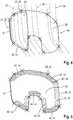
- FIG. 4the reference objects 28 derived from the field-specific data for the field 30 are shown.
- a reference object 28 in the form of a reference edge 32has been selected as the reference line 36, for example by the operator, the reference line 36 serving as input information for the further processing planning and the preparation of the processing plan.
- tramlines 38are generated and displayed by the planning system 22.
- the tramlines 38are arranged substantially parallel to the selected reference line 36, in particular distributed on the field 30.
- the generated tramlines 38are used to create an editing route for the field to be processed 30. It can further information, such as machine-specific data such as attachments or working width, are taken into account.
- the tramlines 38are shown as lines which are arranged substantially parallel to the reference line 36 and intersect the field border 44. Furthermore, in FIG. 3 a reference object 28 in the form of a reference surface 40 is shown. This reference area 40 represents a partial area of the field 30. This reference area 40 can be generated and suggested automatically by the planning system 22, for example based on preselection criteria, or created by the operator. As a result, a meaningful subdivision of a field 30 for processing, in particular with individual and / or combined processing plans, can be carried out by the operator.
- reference surfaces 40are shown, which are based on the selection of the reference object 28 as a reference line 36.
- the reference surfaces 40indicate to the operator areas to choose from, which in the, as already in FIG. 3 shown, as reference line 36 selected reference object 28 can be used as headland areas 42. in this connection may be particularly emphasized as reference surfaces 40, which are preferably usable as headland areas 42, for example by a darker coloration. From the displayed reference areas 40, the areas to be used as headland areas 42 can be selected by the operator.
- the selected as headland areas 42 reference surfaces 40serve the planning system 22 as input information for the preparation of the processing plan, in the headland areas, the agricultural machine can turn, for example, to retract in the opposite direction in the next provided tram 38 and continue the processing of the field 30 ,
- the headland selected by the operator headlands 42may also be useful as input information for an automated headland control of the agricultural work machine 10, which may be part of the processing plan.
- the creation of the processing plan for the agricultural work machine 10 based on the selection of reference objects 28 by the operatormay include the generation of information for controlling implements of the agricultural machine 10. This may be, for example, information for controlling the agricultural work machine 10 and / or for controlling attachments of the agricultural work machine 10, such as a fertilizer spreader.
Landscapes
- Engineering & Computer Science (AREA)
- Radar, Positioning & Navigation (AREA)
- Remote Sensing (AREA)
- Life Sciences & Earth Sciences (AREA)
- Physics & Mathematics (AREA)
- General Physics & Mathematics (AREA)
- Automation & Control Theory (AREA)
- Mechanical Engineering (AREA)
- Soil Sciences (AREA)
- Environmental Sciences (AREA)
- Aviation & Aerospace Engineering (AREA)
- Business, Economics & Management (AREA)
- Marine Sciences & Fisheries (AREA)
- Marketing (AREA)
- Animal Husbandry (AREA)
- Health & Medical Sciences (AREA)
- Economics (AREA)
- General Health & Medical Sciences (AREA)
- Human Resources & Organizations (AREA)
- Mining & Mineral Resources (AREA)
- Primary Health Care (AREA)
- Strategic Management (AREA)
- Tourism & Hospitality (AREA)
- General Business, Economics & Management (AREA)
- Theoretical Computer Science (AREA)
- Agronomy & Crop Science (AREA)
- Management, Administration, Business Operations System, And Electronic Commerce (AREA)
Description
Translated fromGermanDie vorliegende Erfindung betrifft ein Planungssystem zur Planung einer Feldbearbeitung für eine landwirtschaftliche Arbeitsmaschine auf einem Feld, sowie ein Verfahren zur Planung einer Feldbearbeitung für eine landwirtschaftliche Arbeitsmaschine.The present invention relates to a planning system for planning field processing for an agricultural work machine on a field, and to a method for planning field processing for an agricultural work machine.
Nachdem die Leistungsfähigkeit landwirtschaftlicher Arbeitsmaschinen immer weiter gesteigert wurde, gewinnt die Planung und Organisation des Arbeitsablaufes für leistungsstarke Arbeitsmaschinen, wie beispielsweise Mähdrescher, Feldhäcksler, oder anderer landwirtschaftliche Maschinen wie Düngerstreuer oder Sämaschinen immer mehr an Bedeutung. Bei der Planung des Arbeitsablaufes einer landwirtschaftlichen Arbeitsmaschine auf einem Feld ist die Planung einer Bearbeitungsroute, entlang derer die landwirtschaftliche Arbeitsmaschine das Feld befährt, von zunehmendem Interesse, da beispielsweise durch eine entsprechende Routenauswahl die kürzeste Strecke ermittelt werden kann, die für die Bearbeitung des gesamten Feldes benötigt wird, wodurch Zeit und Kraftstoff eingespart werden kann. Die Planung vorteilhafter Bearbeitungsrouten beinhaltet auch die Planung entsprechender Vorgewendebereiche, in denen die landwirtschaftliche Arbeitsmaschine ihre Fahrtrichtung ändern und beispielsweise parallel zur vorherigen Fahrtrichtung die Bearbeitung des Feldes fortsetzen kann.As the performance of agricultural machinery has steadily increased, the planning and organization of the workflow for high-performance machinery such as combine harvesters, forage harvesters, or other agricultural machinery such as fertilizer spreaders or seed drills is becoming increasingly important. When planning the operation of an agricultural work machine on a field, the planning of an operating route along which the agricultural machine travels the field is of increasing interest, since, for example, by an appropriate route selection, the shortest route can be determined for the processing of the entire field is needed, whereby time and fuel can be saved. The planning of advantageous processing routes also includes the planning of corresponding headland areas in which the agricultural work machine can change its direction of travel and, for example, continue the processing of the field parallel to the previous direction of travel.
Aus der
Aus der
Es ist daher die Aufgabe der Erfindung, ein Planungssystem sowie ein Verfahren für eine landwirtschaftliche Arbeitsmaschine bereitzustellen, die eine vereinfachte Erzeugung von Eingangsinformationen für eine anschließende Bearbeitungsplanung eines Feldes basierend auf feldspezifischen Daten ermöglichen, um so beispielsweise einem Bediener die Planung einer Feldbearbeitung durch Auswahl wesentlicher Eingangsinformationen zu vereinfachen.It is therefore the object of the invention to provide a planning system and a method for an agricultural work machine, which allow a simplified generation of input information for a subsequent processing planning of a field based on field-specific data, such as an operator planning a field processing by selecting essential input information to simplify.
Die Aufgabe wird erfindungsgemäß durch die kennzeichnenden Merkmale der unabhängigen Patentansprüche 1 und 7 gelöst. Vorteilhafte Ausgestaltungen und Weiterbildungen der Erfindung ergeben sich aus den nachstehenden Unteransprüchen und den nachfolgenden Beschreibungen.The object is achieved by the characterizing features of the independent claims 1 and 7. Advantageous embodiments and modifications of the invention will become apparent from the following dependent claims and the following descriptions.
Ein erfindungsgemäßes Planungssystem zur, insbesondere interaktiven, Planung einer Feldbearbeitung für eine landwirtschaftliche Arbeitsmaschine, weist neben einer Anzeigeeinheit eine Datenverarbeitungseinheit zur Verarbeitung feldspezifischer Daten auf. Erfindungsgemäß ist das Planungssystem eingerichtet und ausgebildet, feldspezifische Daten zu erzeugen und/oder vorgegebene feldspezifische Daten in die Datenverarbeitungseinheit zu importieren, aus den feldspezifischen Daten mittels eines in der Datenverarbeitungseinheit hinterlegten Algorithmus mindestens ein Referenzobjekt abzuleiten, das mindestens eine Referenzobjekt auf der Anzeigeeinheit anzuzeigen, wobei mindestens ein Referenzobjekt als Eingangsinformation für die Planung der Bearbeitung des Feldes durch einen Bediener des Planungssystems auswählbar ist, und basierend auf dem mindestens einen ausgewählten Referenzobjekt ein Bearbeitungsplan für die landwirtschaftliche Arbeitsmaschine erstellt wird.An inventive planning system for, in particular interactive, planning a field processing for an agricultural work machine has, in addition to a display unit, a data processing unit for processing field-specific data. According to the invention, the planning system is set up and configured to generate field-specific data and / or to import predetermined field-specific data into the data processing unit, to derive at least one reference object from the field-specific data by means of an algorithm stored in the data processing unit, the at least one reference object display the display unit, wherein at least one reference object as input information for planning the processing of the field by an operator of the planning system is selectable, and based on the at least one selected reference object, a processing plan for the agricultural machine is created.
Das Planungssystem weist neben einer Anzeigeeinheit eine Datenverarbeitungseinheit auf, welche aus feldspezifischen Daten mittels eines Algorithmus ein oder mehrere Referenzobjekte ableiten kann. Referenzobjekte können auf der Anzeigeeinheit angezeigt werden und ermöglichen so einem Bediener, beispielsweise der landwirtschaftlichen Arbeitsmaschine, eine für die weitere Arbeitsplanung des betreffenden Feldes sinnvolle Auswahl aus den angezeigten Referenzobjekten zu treffen. Ein ausgewähltes Referenzobjekte dient dabei als Eingangsinformation für die Erstellung eines Bearbeitungsplanes für die landwirtschaftliche Arbeitsmaschine für das entsprechende Feld.In addition to a display unit, the planning system has a data processing unit which can derive one or more reference objects from field-specific data by means of an algorithm. Reference objects can be displayed on the display unit and thus allow an operator, for example, the agricultural machine, to make a meaningful selection from the displayed reference objects for the further work planning of the relevant field. A selected reference object serves as input information for the creation of a processing plan for the agricultural machine for the corresponding field.
Die Auswahl von Referenzobjekten als Eingangsinformation durch den Bediener des Planungssystems hat den Vorteil, dass durch den Bediener bestimmt werden kann, welche Referenzobjekte und damit welche Eingangsinformationen für die weitere Bearbeitungsplanung relevant und zu berücksichtigen sind. Dadurch kann eine weitergehende aufwändige automatische Analyse der feldspezifischen Daten und/oder Referenzobjekte vermieden werden. Zudem kann das Wissen und die Erfahrung des Bedieners, insbesondere im Bezug auf ein zu bearbeitendes Feld, berücksichtigt werden. Somit kann durch den interaktiven Schritt der Auswahl von feldspezifischen Referenzobjekten als Eingangsinformation die Erstellung eines Bearbeitungsplanes für eine landwirtschaftliche Arbeitsmaschine vereinfacht werden.The selection of reference objects as input information by the operator of the planning system has the advantage that it is possible to determine by the operator which reference objects and thus which input information are relevant for the further processing planning and must be taken into account. As a result, a more extensive, automatic analysis of the field-specific data and / or reference objects can be avoided. In addition, the knowledge and experience of the operator, especially in relation to a field to be processed, can be taken into account. Thus, through the interactive step of selecting field specific reference objects as input information, the creation of a processing plan for an agricultural work machine can be simplified.
In einer bevorzugten Ausgestaltung der Erfindung enthalten die feldspezifischen Daten Informationen zu einer Feldumrandung, äußeren und/oder inneren Feldgrenzen, und/oder geografischen Besonderheiten, insbesondere des Feldes. Durch die in den feldspezifischen Daten hinterlegten Informationen zu einer Feldumrandung, zu äußeren und/oder inneren Feldgrenzen und/oder geografischen Besonderheiten kann die Erstellung eines Bearbeitungsplanes weiter vereinfacht werden, da hierdurch die für die Ableitung eines Referenzobjektes benötigten Informationen ohne weitere Aufbereitung der Daten nutzbar sind.In a preferred embodiment of the invention, the field-specific data contain information about a field border, outer and / or inner field boundaries, and / or geographic features, in particular of the field. The information stored in the field-specific data on a field border, outer and / or inner field boundaries and / or geographical features, the creation of a processing plan can be further simplified, as a result The information required for the derivation of a reference object can be used without further processing of the data.
In einer besonders bevorzugten Ausgestaltung der Erfindung ist der Algorithmus zur Ableitung eines Referenzobjektes aus den feldspezifischen Daten ein Kantenerkennungsalgorithmus. Der Algorithmus, insbesondere der Kantenerkennungsalgorithmus, kann in der Datenverarbeitungseinrichtung hinterlegt sein. Die feldspezifischen Daten können vor einem Ableiten von Referenzobjekten mittels des Kantenerkennungsalgorithmus aufbereitet werden, um beispielsweise eine grafische Darstellung, insbesondere in Linienform, zu ermöglichen, wodurch eine vereinfachte Ableitung der Referenzobjekte ermöglicht werden kann. Die mittels des Kantenerkennungsalgorithmus abgeleiteten Referenzobjekte können beispielsweise in Form von Linien und/oder Flächen, beispielsweise durch Anzeige einer Flächenumrandung, dargestellt werden. Der Kantenerkennungsalgorithmus ermöglicht die Nutzung von einfachen grafischen Darstellungen eines Feldes, wodurch eine aufwändige Datenaufbereitung zur Ermittlung der Referenzobjekte vermeidbar ist, da beispielsweise auch digitalisierte Kartenansichten oder Zeichnungen, beispielsweise aus Flurkarten, eines entsprechenden Feldes zur Erstellung eines Bearbeitungsplanes verwendet werden können.In a particularly preferred embodiment of the invention, the algorithm for deriving a reference object from the field-specific data is an edge detection algorithm. The algorithm, in particular the edge detection algorithm, can be stored in the data processing device. The field-specific data can be processed before deriving reference objects by means of the edge detection algorithm, for example, to enable a graphical representation, in particular in line form, whereby a simplified derivation of the reference objects can be made possible. The reference objects derived by means of the edge detection algorithm can be represented, for example, in the form of lines and / or surfaces, for example by displaying a surface border. The edge detection algorithm allows the use of simple graphical representations of a field, whereby a complex data preparation for determining the reference objects is avoidable, since, for example, digitized map views or drawings, for example, from land maps, a corresponding field can be used to create a machining plan.
In einer besonders vorteilhaften Ausgestaltung der Erfindung ist ein Referenzobjekt eine Referenzkante und/oder ein Eckpunkt, wobei die Referenzkante durch zwei Eckpunkte begrenzbar ist. Die Referenzkante kann ein Teilabschnitt und/oder Teilausschnitt eines Referenzobjektes sein, beispielsweise ein Abschnitt einer Feldumrandung, einer äußeren oder inneren Feldgrenze. Eine Referenzkante kann sich dabei zwischen zwei Eckpunkte erstrecken und kann durch diese begrenzt sein. Dies hat den Vorteil, dass dadurch ein definierter Abschnitt und/oder Ausschnitt aus einem Referenzobjekt abgeleitet und insbesondere angezeigt werden kann. Das Ableiten einer Referenzkante ermöglicht eine präzisere Auswahl und Bestimmung der Eingangsdaten für die Erstellung des Bearbeitungsplanes, wodurch die Genauigkeit des Bearbeitungsplans verbessert werden kann.In a particularly advantageous embodiment of the invention, a reference object is a reference edge and / or a vertex, wherein the reference edge can be limited by two corner points. The reference edge may be a subsection and / or partial section of a reference object, for example a section of a field border, an outer or inner field boundary. A reference edge may extend between two corner points and may be limited by these. This has the advantage that thereby a defined section and / or section can be derived from a reference object and in particular displayed. Deriving a reference edge allows a more precise selection and determination of the input data for the creation of the machining plan, whereby the accuracy of the machining plan can be improved.
Vorteilhafter Weise ist ein Referenzobjekt basierend auf einer automatischen Vorauswahl auf der Anzeigeeinheit anzeigbar. Die auf der Anzeigeeinheit dargestellten Referenzobjekte, insbesondere Referenzkanten, können basierend auf vordefinierbaren Einstellungen vorausgewählt sein, wobei zumindest ein Teil der aus den feldspezifischen Daten abgeleiteten Referenzobjekte anzeigbar ist. Eine Vorauswahl der angezeigten Referenzobjekte, insbesondere Referenzkanten, bietet den Vorteil, dass beispielsweise nur die überhaupt als Eingangsinformation nutzbaren Referenzobjekte angezeigt werden. Zudem kann durch eine Vorauswahl der angezeigten Referenzobjekte die Arbeitsbelastung des Bedieners verringert werden, da durch die Vorauswahl der Referenzobjekte die Anzahl der Auswahlmöglichkeiten für den Bediener verringert werden kann.Advantageously, a reference object based on an automatic preselection on the display unit can be displayed. The displayed on the display unit Reference objects, in particular reference edges, may be preselected based on predefinable settings, with at least a portion of the reference objects derived from the field-specific data being able to be displayed. A preselection of the displayed reference objects, in particular reference edges, offers the advantage that, for example, only the reference objects that can be used at all as input information are displayed. In addition, a pre-selection of the displayed reference objects, the workload of the operator can be reduced, since the preselection of the reference objects, the number of choices for the operator can be reduced.
In einer weiteren vorteilhaften Ausgestaltung der Erfindung sind basierend auf dem mindestens einen ausgewählten Referenzobjekt als Eingangsinformation Referenzlinien zur Erstellung von Bearbeitungsrouten, Teilfelder und/oder Vorgewendebereiche erstellbar. Ein Referenzobjekt kann linienförmig, beispielsweise als Referenzkante, oder flächig dargestellt werden. Ein flächiges Referenzobjekt kann beispielsweise auch durch eine Auswahl und Verbindung mehrerer Eckpunkte gebildet werden. Basierend auf einem als Eingangsinformation für die Bearbeitungsplanung ausgewählten linienförmigen Referenzobjekt , insbesondere einer Referenzkante, kann eine diesem Referenzobjekt zugeordnete Referenzlinie erstellt werden, welche als Grundlage für die Planung einer Bearbeitungsroute dienen kann. Eine Bearbeitungsroute für ein Feld ist dabei die gesamte abzufahrende Route zur Bearbeitung des Feldes, wobei eine Bearbeitungsroute dabei mehrere, beispielsweise im Wesentlichen parallel auf dem Feld angeordnete Fahrgassen umfassen kann. Zudem können durch die Auswahl eines flächigen Referenzobjektes als Eingangsinformation für die Bearbeitungsplanung Teilfelder und/oder Vorgewendebereiche erstellt werden, welche in der Planung der Bearbeitung berücksichtigt werden. Durch die Erstellung unterschiedlicher Planungsabschnitte, beispielsweise von Bearbeitungsrouten, Teilflächen und/oder Vorgewendebereichen, basierend auf der Auswahl eines entsprechenden Referenzobjektes durch den Bediener kann die Erstellung des Bearbeitungsplanes weiter vereinfacht werden.In a further advantageous embodiment of the invention, based on the at least one selected reference object, reference lines for creating processing routes, subfields and / or headland areas can be created as input information. A reference object can be displayed linearly, for example as a reference edge, or flat. A planar reference object can also be formed, for example, by selecting and connecting a plurality of corner points. Based on a selected as input information for the machining planning linear reference object, in particular a reference edge, a reference object associated with this reference line can be created, which can serve as a basis for the planning of an editing route. An editing route for a field is the entire route to be traveled for processing the field, wherein an editing route may include a plurality of tramlines arranged substantially parallel to the field, for example. In addition, partial fields and / or headland areas can be created by selecting a planar reference object as input information for the machining planning, which are taken into account in the planning of the machining. By creating different planning sections, such as machining routes, sub-areas and / or headland areas, based on the selection of a corresponding reference object by the operator, the creation of the machining plan can be further simplified.
Vorteilhafterweise sind Referenzobjekte auf der Anzeigeeinheit interaktive darstellbar, wobei die Anzeigeeinheit insbesondere ein Touchscreen-Bildschirm ist. Durch die interaktive Darstellung, insbesondere auf einem als Touchscreen-Bildschirm ausgebildeten Anzeigeeinheit, kann die Auswahl eines angezeigten Referenzobjektes unmittelbar an der Anzeigeeinheit erfolgen, wodurch die Erstellung eines Bearbeitungsplanes weiter vereinfacht werden kann.Advantageously, reference objects can be displayed interactively on the display unit, wherein the display unit is in particular a touchscreen screen. Through the interactive presentation, especially on a screen as a touch screen trained display unit, the selection of a displayed reference object can be done directly on the display unit, whereby the creation of a processing plan can be further simplified.
Weiterhin betrifft die Erfindung eine landwirtschaftliche Arbeitsmaschine mit einem wie oben beschriebenen und ausgebildetem Planungssystem zur Planung einer Feldbearbeitung. Die landwirtschaftliche Arbeitsmaschine kann ein Routenplanungssystem aufweisen, welches ein erfindungsgemäßes Planungssystem und/oder erfindungsgemäßes Verfahren zur Planung umfassen kann.Furthermore, the invention relates to an agricultural work machine with a planning system as described above and trained for planning a field processing. The agricultural work machine can have a route planning system, which can include a planning system according to the invention and / or planning method according to the invention.
Weiterhin betrifft die Erfindung ein Verfahren zur, insbesondere interaktiven, Planung einer Feldbearbeitung für eine landwirtschaftliche Arbeitsmaschine, wobei feldspezifische Daten erzeugt und/oder vorgegebene feldspezifische Daten importiert werden und in eine Datenverarbeitungseinheit eingegeben werden, aus den feldspezifischen Daten mittels eines in der Datenverarbeitungseinheit hinterlegten Algorithmus mindestens ein Referenzobjekt abgeleitet wird, mindestens ein Referenzobjekt auf der Anzeigeeinheit angezeigt wird, mindestens ein Referenzobjektes als Eingangsinformation für die Planung der Bearbeitung des Feldes durch einen Bediener des Planungssystems ausgewählt wird und ein Bearbeitungsplan für die landwirtschaftliche Arbeitsmaschine basierend auf dem mindestens einen ausgewählten Referenzobjekt erstellt wird.Furthermore, the invention relates to a method for, in particular interactive, planning a field processing for an agricultural machine, wherein field-specific data is generated and / or predetermined field-specific data are imported and entered into a data processing unit, from the field-specific data by means of an algorithm stored in the data processing unit at least a reference object is derived, at least one reference object is displayed on the display unit, at least one reference object is selected as input information for planning the processing of the field by an operator of the planning system and a processing plan for the agricultural machine is created based on the at least one selected reference object.
Durch das Verfahren können aus feldspezifischen Daten abgeleitete Referenzobjekte auf der Anzeigeeinheit angezeigt werden und ermöglichen so einem Bediener eine für die weitere Arbeitsplanung des betreffenden Feldes sinnvolle Auswahl aus den angezeigten Referenzobjekten zu treffen. Das oder die ausgewählten Referenzobjekte dienen als Eingangsinformation für die Erstellung eines Bearbeitungsplanes für die landwirtschaftliche Arbeitsmaschine für das entsprechende Feld. Das interaktive, wechselseitige Aufeinander-Reagieren zwischen dem Bediener und dem Planungssystem, insbesondere die Auswahl von Referenzobjekten als Eingangsinformation durch den Bediener des Planungssystems hat den Vorteil, dass durch den Bediener bestimmt werden kann, welche Referenzobjekte und damit welche Eingangsinformationen für die weitere Bearbeitungsplanung relevant und zu berücksichtigen sind. Dadurch kann eine weitergehende, aufwändige automatische Analyse der feldspezifischen Daten und/oder Referenzobjekte vermieden werden. Zudem kann das Wissen und die Erfahrung des Bedieners, insbesondere im Bezug auf ein zu bearbeitendes Feld, berücksichtigt werden. Somit kann durch den interaktiven Schritt der Auswahl von feldspezifischen Referenzobjekten als Eingangsinformation die Erstellung eines Bearbeitungsplanes für eine landwirtschaftliche Arbeitsmaschine vereinfacht werden.By means of the method, reference objects derived from field-specific data can be displayed on the display unit and thus make it possible for an operator to make a meaningful selection from the displayed reference objects for the further work planning of the relevant field. The selected reference object (s) serve as input information for the creation of a processing plan for the agricultural work machine for the corresponding field. The interactive, mutual interaction between the operator and the planning system, in particular the selection of reference objects as input information by the operator of the planning system has the advantage that can be determined by the operator, which reference objects and thus which input information for further processing planning relevant and to take into account. This allows a more extensive, complex automatic analysis of the field-specific data and / or reference objects are avoided. In addition, the knowledge and experience of the operator, especially in relation to a field to be processed, can be taken into account. Thus, through the interactive step of selecting field specific reference objects as input information, the creation of a processing plan for an agricultural work machine can be simplified.
In einer bevorzugten Weiterbildung des Verfahrens wird das mindestens eine Referenzobjekt mittels eines Kantenerkennungsalgorithmus abgeleitet, wobei als Referenzobjekt eine, insbesondere durch zwei Eckpunkte begrenzte, Referenzkante generierbar ist. Die Referenzkante eine Mehrzahl an Eckpunkten verbinden oder durchlaufen, wobei die Form der Referenzkante durch die Anordnung der begrenzenden und durchlaufenen Eckpunkten definiert werden kann. Der Kantenerkennungsalgorithmus ermöglicht die Nutzung von einfachen grafischen Darstellungen eines Feldes, wodurch eine aufwändige Datenaufbereitung zur Ermittlung der Referenzobjekte vermeidbar ist. Die Generierung einer Referenzkante, welche zwei Eckpunkte verbindet und durch diese begrenzt sein kann, hat den Vorteil, dass dadurch ein definierter Abschnitt und/oder Ausschnitt aus einem Referenzobjekt abgeleitet und insbesondere angezeigt werden kann, wodurch eine präzisere Auswahl und Bestimmung der Eingangsdaten für die Erstellung des Bearbeitungsplanes ermöglicht werden kann.In a preferred embodiment of the method, the at least one reference object is derived by means of an edge detection algorithm, wherein a reference edge, in particular bounded by two corner points, can be generated as the reference object. The reference edge connect or traverse a plurality of vertices, wherein the shape of the reference edge can be defined by the arrangement of the bounding and traversed vertices. The edge detection algorithm allows the use of simple graphical representations of a field, whereby a complex data preparation for the determination of the reference objects is avoidable. The generation of a reference edge, which connects two vertices and may be limited by these, has the advantage that thereby a defined section and / or section can be derived from a reference object and in particular displayed, whereby a more precise selection and determination of the input data for the creation the machining plan can be enabled.
In einer weiteren Ausgestaltung basiert eine Anzeige eines Referenzobjektes auf der Anzeigeeinheit auf einer automatisierten Vorauswahl. Dadurch, dass aus den abgeleiteten Referenzobjekten eine Vorauswahl getroffen wird, welche Referenzobjekte angezeigt werden, können beispielsweise nur die Referenzobjekte angezeigt werden, die als Eingangsinformation für eine Erstellung eines Bearbeitungsplanes nutzbar sind, wodurch die Arbeitsbelastung des Bedieners weiter verringert werden kann.In a further refinement, a display of a reference object on the display unit is based on an automated preselection. By preselecting from the derived reference objects which reference objects are displayed, for example, only the reference objects that can be used as input for creating a processing plan can be displayed, whereby the workload of the operator can be further reduced.
Vorzugsweise basiert die Vorauswahl eines Referenzobjektes auf der Erfüllung mindestens eines Vorauswahlkriteriums, wobei ein Vorauswahlkriterium eine Länge und/oder eine Krümmung eines Referenzobjektes sein kann. Die Vorauswahlkriterien sind besonders geeignet, die durch die Kantenerkennung abgeleiteten Referenzobjekte, beispielsweise eine Referenzkante, zu bewerten. Eine Länge und/oder eine Krümmung eines durch den Kantenerkennungsalgorithmus abgeleiteten Referenzobjektes, beispielsweise in Form einer Referenzkante, sind hierbei besonders effektiv anzuwenden. Dadurch kann eine zuverlässige Vorauswahl zur Anzeige von Referenzobjekten getroffen werden, welche für die Erstellung eines Bearbeitungsplanes nutzbar sind.Preferably, the preselection of a reference object is based on the fulfillment of at least one preselection criterion, wherein a pre-selection criterion may be a length and / or a curvature of a reference object. The preselection criteria are particularly suitable, the reference objects derived by the edge detection, for example, a reference edge to rate. A length and / or a curvature of a reference object derived by the edge detection algorithm, for example in the form of a reference edge, are to be used particularly effectively here. As a result, a reliable pre-selection for the display of reference objects can be made, which can be used for the creation of a processing plan.
In einer besonders bevorzugten Weiterbildung des Verfahrens werden aufgrund des mindestens einen ausgewählten Referenzobjektes Referenzlinien, Teilfelder und/oder Vorgewendebereiche als Eingangsinformation zum Erstellen eines Bearbeitungsplanes erstellt. Ein Referenzobjekt kann linienförmig, beispielsweise als Referenzkante, oder flächig dargestellt werden, wobei ein flächiges Referenzobjekt, eine Referenzfläche, beispielsweise auch durch eine Auswahl und Verbindung mehrerer Eckpunkte gebildet werden kann. Referenzobjekte können durch ihre Form und/oder Anordnung zur Planung unterschiedlicher Planungsabschnitte, beispielsweise als Referenzlinie oder als Vorgewendebereich, ausgewählt werden, wobei die Erstellung eines Bearbeitungsplanes auf mindestens einem Planungsabschnitt basieren kann . Dies hat den Vorteil, dass durch die Auswahl eines entsprechenden Referenzobjektes, und insbesondere eines mit diesem verbundenen Planungsabschnittes, die Erstellung des Bearbeitungsplanes weiter vereinfacht werden kann.In a particularly preferred development of the method, reference lines, partial fields and / or headland areas are created as input information for creating a processing plan on the basis of the at least one selected reference object. A reference object can be displayed linearly, for example as a reference edge, or flat, wherein a planar reference object, a reference surface, for example, can also be formed by selecting and connecting a plurality of corner points. Reference objects can be selected by their shape and / or arrangement for planning different planning sections, for example as a reference line or as a headland area, wherein the creation of a machining plan can be based on at least one planning section. This has the advantage that the creation of the processing plan can be further simplified by the selection of a corresponding reference object, and in particular of a related planning section.
In einer weiter bevorzugten Ausgestaltung des Verfahrens umfasst die Erstellung des Bearbeitungsplanes für die landwirtschaftliche Arbeitsmaschine die Generierung von Informationen zur Steuerung mindestens eines Anbaugerätes der landwirtschaftlichen Maschine. Dadurch, dass der Bearbeitungsplan für die landwirtschaftliche Arbeitsmaschine Informationen zur Ansteuerung von Anbaugeräten der Arbeitsmaschine umfasst, können zusätzliche Informationen zur Bearbeitung in die Planung aufgenommen und so die durch den Bearbeitungsplan planbare Funktionalität und Einsatzspektrum erhöht werden. Dies hat den Vorteil, dass die Erstellung von Bearbeitungsplänen für eine größere Vielzahl an landwirtschaftlichen Arbeitsmaschinen vorgenommen werden kann.In a further preferred embodiment of the method, the preparation of the processing plan for the agricultural work machine comprises the generation of information for controlling at least one attachment of the agricultural machine. Due to the fact that the processing plan for the agricultural working machine includes information for controlling attachments of the working machine, additional information for processing can be included in the planning and thus the functionality and range of use that can be planned by the processing plan can be increased. This has the advantage that the preparation of machining plans for a larger variety of agricultural machines can be made.
Weitere Merkmale und Vorteile der Erfindung ergeben sich aus der nachfolgenden Beschreibung von Ausführungsbeispielen unter Bezugnahme auf die beigefügten Figuren.Further features and advantages of the invention will become apparent from the following description of embodiments with reference to the accompanying figures.
Es zeigen:
- Fig. 1:
- eine schematische Darstellung einer landwirtschaftlichen Arbeitsmaschine;
- Fig. 2:
- eine schematische Darstellung von Referenzobjekten eines Feldes;
- Fig. 3:
- eine schematische Darstellung einer Anzeige von vorausgewählten Referenzobjekten;
- Fig. 4:
- eine schematische Darstellung von Fahrgassen und einer Teilfläche nach Auswahl eines Referenzobjektes; und
- Fig. 5:
- eine schematische Darstellung von Vorgewendebereichen, deren Erstellung auf der Auswahl einer Referenzlinie basiert.
- Fig. 1:
- a schematic representation of an agricultural machine;
- Fig. 2:
- a schematic representation of reference objects of a field;
- 3:
- a schematic representation of a display of preselected reference objects;
- 4:
- a schematic representation of tramlines and a subarea after selecting a reference object; and
- Fig. 5:
- a schematic representation of headland areas whose creation is based on the selection of a reference line.
In
Zum Überwachen und/oder Steuern unterschiedlicher Funktionen der landwirtschaftlichen Arbeitsmaschine 10 ist in einer Fahrerkabine 18 der landwirtschaftlichen Arbeitsmaschine 10 eine Anzeigeeinheit 20 angeordnet. Auf der Anzeigeeinheit 20 kann einem Bediener der landwirtschaftlichen Arbeitsmaschine 10 der Bearbeitungsplan angezeigt werden. Der feldspezifische Bearbeitungsplan für die landwirtschaftliche Arbeitsmaschine 10 kann in einem Planungssystem 22 mit einer Datenverarbeitungseinheit 24 erstellt und/oder hinterlegt werden, wobei das Planungssystem 22 mit der Datenverarbeitungseinheit 24 auf der landwirtschaftlichen Maschine 10 angeordnet sein kann. Das Planungssystem 22 mit der Datenverarbeitungseinheit 24 kann auch beabstandet zu der landwirtschaftlichen Arbeitsmaschine 10, beispielsweise in einem Büro, angeordnet sein, wobei der Bearbeitungsplan über ein Kommunikationsmodul 26, beispielsweise über eine Mobilfunk- oder WLAN-Verbindung, zu der landwirtschaftlichen Maschine 10 übertragen werden kann. Das Planungssystem 22, die Datenverarbeitungseinrichtung 24 und/oder das Kommunikationsmodul 26 können in die Anzeigeeinheit 20 integriert sein. Die Anzeigeeinheit 20 kann zur Anzeige und Eingabe von Informationen einen Touchscreen-Bildschirm aufweisen. Bei einer Anzeigeeinheit 20 mit einem Touchscreen-Bildschirm ist neben einer Anzeige auch eine Interaktion mit den angezeigten Informationen, beispielsweise zur Erstellung oder Änderung des Bearbeitungsplanes, möglich.For monitoring and / or controlling different functions of the agricultural working
Das Planungssystem 22, insbesondere ein auf der landwirtschaftlichen Arbeitsmaschine 10 angeordnetes Planungssystem 22, kann zudem weitere für die Erstellung eines Bearbeitungsplanes hilfreiche Komponenten aufweisen. Dies können beispielsweise Sensoren zur Erfassung und/oder Erstellung feldspezifischer Daten sein, beispielsweise eine Positionsermittlungseinrichtung in Form eines GPS-Empfängers. Feldspezifische Daten können beispielsweise Daten sein, die Informationen über den Umfang, über äußere und/oder innere Feldgrenzen oder geografische Besonderheiten eines zu bearbeitenden Feldes enthalten. Geografische Besonderheiten eines Feldes können dabei Hindernisse oder einzuhaltende Fahrspuren, beispielsweise bei dem sogenannten Controlled Traffic Farming, sein, die bei der Erstellung eines Bearbeitungsplanes zu berücksichtigen sind.The
Diese feldspezifischen Daten zur Erstellung eines Bearbeitungsplanes können bereits bekannt sein, also vorgegebene Daten sein, oder müssen vor der Erstellung des Bearbeitungsplanes generiert werden. Vorgegebene Daten können in dem Planungssystem 22, beispielsweise in einer Speichereinheit, hinterlegt sein, oder in das Planungssystem 22 importiert oder eingegeben werden. Ein Generieren der feldspezifischen Daten kann beispielsweise durch Abfahren der äußeren und/oder inneren Feldgrenzen erfolgen. Die feldspezifischen Daten können dabei in grafischer Form, beispielsweise als Bilddatei oder Kartenabbildung, und/oder in Form von geografischen Koordinaten vorliegen oder erstellt werden. Um eine Ableitung mindestens eines Referenzobjektes aus den feldspezifischen Daten mittels eines erfindungsgemäßen Algorithmus zu ermöglichen, können diese in eine zur Anwendung des Algorithmus geeignete Form aufbereitet werden, beispielsweise durch eine Visualisierung in Form einer linienförmigen und/oder flächigen Darstellung der feldspezifischen Daten.These field-specific data for the creation of a processing plan may already be known, that is, given data, or must be before the creation of the machining plan. Predetermined data can be stored in the
In erfindungsgemäßer Weise können die feldspezifischen Daten mittels eines in der Datenverarbeitungseinrichtung 24 hinterlegten Algorithmus bearbeitet werden. Der Algorithmus ist vorzugsweise ein Kantenerkennungsalgorithmus, der es ermöglicht, aus den feldspezifischen Daten Referenzobjekte 28 abzuleiten, welche als Eingangsinformationen für die Erstellung eines Bearbeitungsplanes nutzbar sind.In accordance with the invention, the field-specific data can be processed by means of an algorithm stored in the
In
Die abgeleiteten Referenzobjekte 28 können dem Bediener des Planungssystems zur Auswahl mindestens eines Referenzobjektes 28 als Eingangsinformation für die Erstellung des Bearbeitungsplanes auf der Anzeigeeinheit 20 dargestellt werden. Ausgehend von den abgeleiteten und dem mindestens einen ausgewählten Referenzobjekt 28 können unterschiedliche Eingangsinformationen für die Erstellung eines Bearbeitungsplanes generiert werden.The derived reference objects 28 can be displayed to the operator of the planning system for selecting at least one
Die aus den feldspezifischen Daten abgeleiteten Referenzobjekte 28 können basierend auf eine automatischen Vorauswahl auf der Anzeigeeinheit 20 angezeigt werden. Durch eine Vorauswahl der angezeigten Referenzobjekte 28 können beispielsweise nur die Referenzobjekte 28 angezeigt werden, die für eine weitere Erstellung des Bearbeitungsplanes nutzbar sind. Zudem kann die Arbeitsbelastung des Bediener des Planungssystems durch eine Anzeige vorausgewählter Referenzobjekte 28 gesenkt werden, da der Bediener nicht mehr zwischen allen abgeleiteten Referenzobjekten 28 auswählen muss. Eine auf einer Vorauswahl basierende Anzeige von Referenzobjekten 28 auf einer Anzeigeeinheit 20 ist in
Eine Vorauswahl der in
Ausgehend von den abgeleiteten und dem mindestens einen ausgewählten Referenzobjekt 28 können unterschiedliche Eingangsinformationen für die Erstellung eines Bearbeitungsplanes generiert werden. In
In
- 1010
- landwirtschaftliche Arbeitsmaschineagricultural working machine
- 1212
- Vorsatzgerätheader
- 1414
- Einzugsaggregatintake assembly
- 1616
- ÜberladekrümmerÜberladekrümmer
- 1818
- Fahrerkabinecab
- 2020
- Anzeigeeinheitdisplay unit
- 2222
- Planungssystemplanning system
- 2424
- DatenverarbeitungseinheitData processing unit
- 2626
- Kommunikationsmodulcommunication module
- 2828
- Referenzobjektreference object
- 3030
- Feldfield
- 3232
- Referenzkantereference edge
- 3434
- Eckpunktevertices
- 3636
- Referenzliniereference line
- 3838
- Fahrgassetramline
- 4040
- Referenzflächereference surface
- 4242
- VorgewendebereichTurnaround area
- 4444
- FeldumrandungSurrounds
Claims (12)
- Planning system for planning, in an interactive manner, fieldwork for an agricultural work machine (10), wherein, in addition to a display unit (20), the planning system (22) has a data processing unit (24) for processing field-specific data, wherein the planning system (22) is equipped and designed to generate field-specific data and/or to import predetermined field-specific data into the data processing unit (24), to derive reference objects (28) from the field-specific data using an algorithm stored in the data processing unit (24), to display the reference objects (28) on the display unit (20), wherein at least one reference object (28) can be selected, as input information for planning the working of the field (30), by an operator of the planning system (22), and a work plan for the agricultural work machine (10) is created on the basis of the at least one selected reference object (28) wherein a reference object (28) is a reference edge (32) and/or a corner point (34), wherein the reference edge (32) can be delimited by two corner points (34), wherein the planning system ischaracterized in that the algorithm for deriving a reference object (28) from the field-specific data is an edge detection algorithm.
- Planning system according to claim 1,characterized in that the field-specific data contain information about a field periphery (44), outer and/or inner field boundaries, and/or geographical features.
- Planning system according to one of the previous claims,characterized in that a reference object (28) can be displayed on the display unit (20) on the basis of an automatic preselection.
- Planning system according to one of the previous claims,characterized in that reference lines (36) for creating work routes, sub-fields and/or headland regions (42) can be generated on the basis of the at least one selected reference object (28) as input information.
- Planning system according to one of the previous claims,characterized in that reference objects (28) can be depicted interactively on the display unit (20), wherein the display unit (20) is a touchscreen monitor.
- Agricultural work machine (10) with a planning system (22) according to claims 1 to 5.
- Method for planning, in an interactive manner, fieldwork for an agricultural work machine (10), wherein- field-specific data are generated and/or predetermined field-specific data are imported and entered into a data processing unit (24),- reference objects (28) are derived from the field-specific data using an algorithm stored in the data processing unit (24),- the reference objects (28) are displayed on a display unit (20),- at least one reference object (28) is selected, as input information for planning the working of the field (30), by an operator of the planning system (22), and a work plan for the agricultural work machine (10) is created on the basis of the at least one selected reference object (28), wherein a reference object (28) is a reference edge (32) and/or a corner point (34), wherein the reference edge (32) can be delimited by two corner points (34), wherein the method ischaracterized in that the algorithm for deriving a reference object (28) from the field-specific data is an edge detection algorithm.
- Method according to claim 7,characterized in that the at least one reference object (28) is derived using an edge detection algorithm, wherein a reference edge (32) having at least two corner points (34) can be generated as reference object (28).
- Method according to claim 7 or 8,characterized in that a display of a reference object (28) on the display unit (20) is based on an automated preselection.
- Method according to claim 9,characterized in that the preselection of a reference object (28) is based on the fulfilment of at least one preselection criterion, wherein a preselection criterion can be a length and/or a curvature of a reference object (28).
- Method according to one of claims 8 to 10,characterized in that, on the basis of the at least one selected reference object (28), reference lines (36), sub-fields and/or headland regions (42) are generated as input information for creating a work plan.
- Method according to one of claims 8 to 11,characterized in that the creation of the work plan for the agricultural work machine (10) comprises the generation of information for controlling at least one attachment unit of the agricultural machine.
Applications Claiming Priority (1)
| Application Number | Priority Date | Filing Date | Title |
|---|---|---|---|
| DE102014104619.6ADE102014104619A1 (en) | 2014-04-02 | 2014-04-02 | Planning system and method for planning fieldwork |
Publications (3)
| Publication Number | Publication Date |
|---|---|
| EP2927767A2 EP2927767A2 (en) | 2015-10-07 |
| EP2927767A3 EP2927767A3 (en) | 2016-02-17 |
| EP2927767B1true EP2927767B1 (en) | 2018-11-28 |
Family
ID=52626961
Family Applications (1)
| Application Number | Title | Priority Date | Filing Date |
|---|---|---|---|
| EP15152147.3AActiveEP2927767B1 (en) | 2014-04-02 | 2015-01-22 | Planning system and method for planning the treatment of a field |
Country Status (4)
| Country | Link |
|---|---|
| US (1) | US20150285647A1 (en) |
| EP (1) | EP2927767B1 (en) |
| DE (1) | DE102014104619A1 (en) |
| RU (1) | RU2701892C2 (en) |
Families Citing this family (64)
| Publication number | Priority date | Publication date | Assignee | Title |
|---|---|---|---|---|
| DE102017123592A1 (en)* | 2017-10-11 | 2019-04-11 | Amazonen-Werke H. Dreyer Gmbh & Co. Kg | Agricultural machine |
| US12026944B2 (en)* | 2017-10-24 | 2024-07-02 | Basf Agro Trademarks Gmbh | Generation of digital cultivation maps |
| CN109029418A (en)* | 2018-05-29 | 2018-12-18 | 威马智慧出行科技(上海)有限公司 | A method of vehicle is positioned in closed area |
| DE102018209607A1 (en)* | 2018-06-14 | 2019-12-19 | Volkswagen Aktiengesellschaft | Method and device for determining a position of a motor vehicle |
| US11641800B2 (en) | 2020-02-06 | 2023-05-09 | Deere & Company | Agricultural harvesting machine with pre-emergence weed detection and mitigation system |
| US11589509B2 (en) | 2018-10-26 | 2023-02-28 | Deere & Company | Predictive machine characteristic map generation and control system |
| US11240961B2 (en) | 2018-10-26 | 2022-02-08 | Deere & Company | Controlling a harvesting machine based on a geo-spatial representation indicating where the harvesting machine is likely to reach capacity |
| US11079725B2 (en) | 2019-04-10 | 2021-08-03 | Deere & Company | Machine control using real-time model |
| US11178818B2 (en) | 2018-10-26 | 2021-11-23 | Deere & Company | Harvesting machine control system with fill level processing based on yield data |
| US11467605B2 (en) | 2019-04-10 | 2022-10-11 | Deere & Company | Zonal machine control |
| US11653588B2 (en) | 2018-10-26 | 2023-05-23 | Deere & Company | Yield map generation and control system |
| US11957072B2 (en) | 2020-02-06 | 2024-04-16 | Deere & Company | Pre-emergence weed detection and mitigation system |
| US11672203B2 (en) | 2018-10-26 | 2023-06-13 | Deere & Company | Predictive map generation and control |
| US12069978B2 (en) | 2018-10-26 | 2024-08-27 | Deere & Company | Predictive environmental characteristic map generation and control system |
| EP3859467B1 (en)* | 2018-12-27 | 2024-05-15 | Honda Motor Co., Ltd. | Information processing device and information processing method |
| US11778945B2 (en) | 2019-04-10 | 2023-10-10 | Deere & Company | Machine control using real-time model |
| US11234366B2 (en) | 2019-04-10 | 2022-02-01 | Deere & Company | Image selection for machine control |
| DE102019210961A1 (en)* | 2019-07-24 | 2021-01-28 | Deere & Company | Method and apparatus for planning the application of agricultural material to a field |
| US12329148B2 (en) | 2020-02-06 | 2025-06-17 | Deere & Company | Predictive weed map and material application machine control |
| US12035648B2 (en) | 2020-02-06 | 2024-07-16 | Deere & Company | Predictive weed map generation and control system |
| US12225846B2 (en) | 2020-02-06 | 2025-02-18 | Deere & Company | Machine control using a predictive map |
| US11477940B2 (en) | 2020-03-26 | 2022-10-25 | Deere & Company | Mobile work machine control based on zone parameter modification |
| US11845449B2 (en) | 2020-10-09 | 2023-12-19 | Deere & Company | Map generation and control system |
| US11727680B2 (en) | 2020-10-09 | 2023-08-15 | Deere & Company | Predictive map generation based on seeding characteristics and control |
| US12419220B2 (en) | 2020-10-09 | 2025-09-23 | Deere & Company | Predictive map generation and control system |
| US12422847B2 (en) | 2020-10-09 | 2025-09-23 | Deere & Company | Predictive agricultural model and map generation |
| US11983009B2 (en) | 2020-10-09 | 2024-05-14 | Deere & Company | Map generation and control system |
| US11675354B2 (en) | 2020-10-09 | 2023-06-13 | Deere & Company | Machine control using a predictive map |
| US11927459B2 (en) | 2020-10-09 | 2024-03-12 | Deere & Company | Machine control using a predictive map |
| US11871697B2 (en) | 2020-10-09 | 2024-01-16 | Deere & Company | Crop moisture map generation and control system |
| US11864483B2 (en) | 2020-10-09 | 2024-01-09 | Deere & Company | Predictive map generation and control system |
| US11849672B2 (en) | 2020-10-09 | 2023-12-26 | Deere & Company | Machine control using a predictive map |
| US11711995B2 (en) | 2020-10-09 | 2023-08-01 | Deere & Company | Machine control using a predictive map |
| US11895948B2 (en) | 2020-10-09 | 2024-02-13 | Deere & Company | Predictive map generation and control based on soil properties |
| US11474523B2 (en) | 2020-10-09 | 2022-10-18 | Deere & Company | Machine control using a predictive speed map |
| US12069986B2 (en) | 2020-10-09 | 2024-08-27 | Deere & Company | Map generation and control system |
| US11946747B2 (en) | 2020-10-09 | 2024-04-02 | Deere & Company | Crop constituent map generation and control system |
| US11592822B2 (en) | 2020-10-09 | 2023-02-28 | Deere & Company | Machine control using a predictive map |
| US11874669B2 (en) | 2020-10-09 | 2024-01-16 | Deere & Company | Map generation and control system |
| US11825768B2 (en) | 2020-10-09 | 2023-11-28 | Deere & Company | Machine control using a predictive map |
| US11635765B2 (en) | 2020-10-09 | 2023-04-25 | Deere & Company | Crop state map generation and control system |
| US11844311B2 (en) | 2020-10-09 | 2023-12-19 | Deere & Company | Machine control using a predictive map |
| US12013245B2 (en) | 2020-10-09 | 2024-06-18 | Deere & Company | Predictive map generation and control system |
| US11889788B2 (en) | 2020-10-09 | 2024-02-06 | Deere & Company | Predictive biomass map generation and control |
| US11650587B2 (en) | 2020-10-09 | 2023-05-16 | Deere & Company | Predictive power map generation and control system |
| US12178158B2 (en) | 2020-10-09 | 2024-12-31 | Deere & Company | Predictive map generation and control system for an agricultural work machine |
| US11849671B2 (en) | 2020-10-09 | 2023-12-26 | Deere & Company | Crop state map generation and control system |
| US12386354B2 (en) | 2020-10-09 | 2025-08-12 | Deere & Company | Predictive power map generation and control system |
| US12250905B2 (en) | 2020-10-09 | 2025-03-18 | Deere & Company | Machine control using a predictive map |
| US11889787B2 (en) | 2020-10-09 | 2024-02-06 | Deere & Company | Predictive speed map generation and control system |
| US11967059B2 (en)* | 2021-05-18 | 2024-04-23 | Deere &Company | Methods and apparatus to identify headlands |
| US11999379B2 (en)* | 2021-08-05 | 2024-06-04 | Cnh Industrial America Llc | Systems and methods for controlling a work vehicle |
| US12229886B2 (en) | 2021-10-01 | 2025-02-18 | Deere & Company | Historical crop state model, predictive crop state map generation and control system |
| US12310286B2 (en) | 2021-12-14 | 2025-05-27 | Deere & Company | Crop constituent sensing |
| US12302791B2 (en) | 2021-12-20 | 2025-05-20 | Deere & Company | Crop constituents, predictive mapping, and agricultural harvester control |
| US12245549B2 (en) | 2022-01-11 | 2025-03-11 | Deere & Company | Predictive response map generation and control system |
| US12082531B2 (en) | 2022-01-26 | 2024-09-10 | Deere & Company | Systems and methods for predicting material dynamics |
| JP7629417B2 (en)* | 2022-02-17 | 2025-02-13 | ヤンマーホールディングス株式会社 | Autonomous driving method, work vehicle, and automated driving system |
| US12295288B2 (en) | 2022-04-05 | 2025-05-13 | Deere &Company | Predictive machine setting map generation and control system |
| US12298767B2 (en) | 2022-04-08 | 2025-05-13 | Deere & Company | Predictive material consumption map and control |
| US12058951B2 (en) | 2022-04-08 | 2024-08-13 | Deere & Company | Predictive nutrient map and control |
| US12284934B2 (en) | 2022-04-08 | 2025-04-29 | Deere & Company | Systems and methods for predictive tractive characteristics and control |
| US12358493B2 (en) | 2022-04-08 | 2025-07-15 | Deere & Company | Systems and methods for predictive power requirements and control |
| CN118859867A (en)* | 2024-07-04 | 2024-10-29 | 山东旭农农业科技有限公司 | A collaborative operation system of multiple intelligent agricultural machinery and supply and transportation agricultural machinery |
Citations (6)
| Publication number | Priority date | Publication date | Assignee | Title |
|---|---|---|---|---|
| DE442211C (en) | 1921-07-23 | 1927-03-24 | Grigori Petroff | Process for the production of liquid condensation products from phenols and formaldehyde |
| DE19629618A1 (en) | 1996-07-23 | 1998-01-29 | Claas Ohg | Route planning system for agricultural work vehicles |
| US6236924B1 (en) | 1999-06-21 | 2001-05-22 | Caterpillar Inc. | System and method for planning the operations of an agricultural machine in a field |
| DE102006002567A1 (en) | 2006-01-18 | 2007-08-02 | Claas Selbstfahrende Erntemaschinen Gmbh | Method of generating reference lanes for agricultural vehicles |
| US20070192024A1 (en) | 2003-03-31 | 2007-08-16 | Deere & Company | Path planner and method for planning a contour path of a vehicle |
| EP2221702A2 (en) | 2009-02-20 | 2010-08-25 | CLAAS Selbstfahrende Erntemaschinen GmbH | Method for creating reference lanes for agricultural vehicles |
Family Cites Families (37)
| Publication number | Priority date | Publication date | Assignee | Title |
|---|---|---|---|---|
| EP0068626B1 (en)* | 1981-07-01 | 1987-08-19 | Imperial Chemical Industries Plc | Vehicle guidance system particularly for use in agriculture |
| IL113913A (en)* | 1995-05-30 | 2000-02-29 | Friendly Machines Ltd | Navigation method and system |
| JP3745472B2 (en)* | 1996-11-18 | 2006-02-15 | 三菱電機株式会社 | Self-propelled vehicle, autonomous guidance device, and automatic transfer device |
| DE29724569U1 (en)* | 1997-06-25 | 2002-05-16 | Claas Selbstfahrende Erntemaschinen GmbH, 33428 Harsewinkel | Device on agricultural machinery for the contactless scanning of contours extending above the ground |
| AUPP679598A0 (en)* | 1998-10-27 | 1998-11-19 | Agsystems Pty Ltd | A vehicle navigation apparatus |
| GB2358843B (en)* | 2000-02-02 | 2002-01-23 | Logical Technologies Ltd | An autonomous mobile apparatus for performing work within a pre-defined area |
| US6285930B1 (en)* | 2000-02-28 | 2001-09-04 | Case Corporation | Tracking improvement for a vision guidance system |
| US6907336B2 (en)* | 2003-03-31 | 2005-06-14 | Deere & Company | Method and system for efficiently traversing an area with a work vehicle |
| DE102004027242A1 (en)* | 2004-06-03 | 2005-12-22 | Claas Selbstfahrende Erntemaschinen Gmbh | Route planning system for agricultural machines |
| DE102004043169A1 (en)* | 2004-09-03 | 2006-03-09 | Claas Selbstfahrende Erntemaschinen Gmbh | Electronic data exchange system |
| US7792607B2 (en)* | 2005-01-04 | 2010-09-07 | Deere & Company | Vision-aided system and method for guiding a vehicle |
| US20060178820A1 (en)* | 2005-02-04 | 2006-08-10 | Novariant, Inc. | System and method for guiding an agricultural vehicle through a recorded template of guide paths |
| DE102006015204A1 (en)* | 2006-03-30 | 2007-10-18 | Claas Selbstfahrende Erntemaschinen Gmbh | Method for creating a route plan for agricultural machine systems |
| DE102006019216A1 (en)* | 2006-04-21 | 2007-10-25 | Claas Selbstfahrende Erntemaschinen Gmbh | Method for controlling an agricultural machine system |
| US8046103B2 (en)* | 2006-09-29 | 2011-10-25 | F Robotics Acquisitions Ltd. | System and method for determining the location of a machine |
| US20090043462A1 (en)* | 2007-06-29 | 2009-02-12 | Kenneth Lee Stratton | Worksite zone mapping and collision avoidance system |
| US8204654B2 (en)* | 2008-03-20 | 2012-06-19 | Deere & Company | System and method for generation of an inner boundary of a work area |
| SE532431C2 (en)* | 2008-05-30 | 2010-01-19 | Atlas Copco Rock Drills Ab | Method and apparatus for determining a correspondence between a representation of an environment and said environment |
| US8099237B2 (en)* | 2008-07-25 | 2012-01-17 | Navteq North America, Llc | Open area maps |
| US9026315B2 (en)* | 2010-10-13 | 2015-05-05 | Deere & Company | Apparatus for machine coordination which maintains line-of-site contact |
| US8112201B2 (en)* | 2008-10-02 | 2012-02-07 | Trimble Navigation Limited | Automatic control of passive, towed implements |
| US8738238B2 (en)* | 2009-11-12 | 2014-05-27 | Deere & Company | Coordination of vehicle movement in a field |
| US10537061B2 (en)* | 2010-02-26 | 2020-01-21 | Cnh Industrial America Llc | System and method for controlling harvest operations |
| US8744626B2 (en)* | 2010-05-27 | 2014-06-03 | Deere & Company | Managing autonomous machines across multiple areas |
| US9134721B2 (en)* | 2011-03-10 | 2015-09-15 | Caterpillar Inc. | Worksite system having awareness zone mapping and control |
| EP3876068B1 (en)* | 2011-04-28 | 2024-10-09 | Positec Power Tools (Suzhou) Co., Ltd | Automatic working system, automatic walking device and steering method thereof |
| US8494726B2 (en)* | 2011-05-16 | 2013-07-23 | Trimble Navigation Ltd. | Agricultural autopilot path adjustment |
| JP5724110B2 (en)* | 2011-07-07 | 2015-05-27 | 株式会社日立製作所 | Route creation system, route creation method and program |
| US9511633B2 (en)* | 2011-08-17 | 2016-12-06 | Deere & Company | Soil compaction management and reporting |
| JP2013228821A (en)* | 2012-04-24 | 2013-11-07 | Mamiya-Op Nequos Co Ltd | Working machine, component device thereof, and computer program |
| US9230339B2 (en)* | 2013-01-07 | 2016-01-05 | Wexenergy Innovations Llc | System and method of measuring distances related to an object |
| WO2014165244A1 (en)* | 2013-03-13 | 2014-10-09 | Pelican Imaging Corporation | Systems and methods for synthesizing images from image data captured by an array camera using restricted depth of field depth maps in which depth estimation precision varies |
| US20140301645A1 (en)* | 2013-04-03 | 2014-10-09 | Nokia Corporation | Method and apparatus for mapping a point of interest based on user-captured images |
| EP2798928B1 (en)* | 2013-04-29 | 2024-02-07 | CLAAS E-Systems GmbH | Operating system for and method of operating an automatic guidance system of an agricultural vehicle |
| US9097520B2 (en)* | 2013-06-12 | 2015-08-04 | Caterpillar Inc. | System and method for mapping a raised contour |
| US9092865B2 (en)* | 2013-08-16 | 2015-07-28 | Lenovo Enterprise Solutions (Singapore) Pte. Ltd. | Map generation for an environment based on captured images |
| US9129192B2 (en)* | 2013-12-16 | 2015-09-08 | Adobe Systems Incorporated | Semantic object proposal generation and validation |
- 2014
- 2014-04-02DEDE102014104619.6Apatent/DE102014104619A1/ennot_activeWithdrawn
- 2015
- 2015-01-22EPEP15152147.3Apatent/EP2927767B1/enactiveActive
- 2015-03-24USUS14/666,833patent/US20150285647A1/ennot_activeAbandoned
- 2015-03-30RURU2015111145Apatent/RU2701892C2/enactive
Patent Citations (6)
| Publication number | Priority date | Publication date | Assignee | Title |
|---|---|---|---|---|
| DE442211C (en) | 1921-07-23 | 1927-03-24 | Grigori Petroff | Process for the production of liquid condensation products from phenols and formaldehyde |
| DE19629618A1 (en) | 1996-07-23 | 1998-01-29 | Claas Ohg | Route planning system for agricultural work vehicles |
| US6236924B1 (en) | 1999-06-21 | 2001-05-22 | Caterpillar Inc. | System and method for planning the operations of an agricultural machine in a field |
| US20070192024A1 (en) | 2003-03-31 | 2007-08-16 | Deere & Company | Path planner and method for planning a contour path of a vehicle |
| DE102006002567A1 (en) | 2006-01-18 | 2007-08-02 | Claas Selbstfahrende Erntemaschinen Gmbh | Method of generating reference lanes for agricultural vehicles |
| EP2221702A2 (en) | 2009-02-20 | 2010-08-25 | CLAAS Selbstfahrende Erntemaschinen GmbH | Method for creating reference lanes for agricultural vehicles |
Also Published As
| Publication number | Publication date |
|---|---|
| RU2701892C2 (en) | 2019-10-02 |
| US20150285647A1 (en) | 2015-10-08 |
| RU2015111145A3 (en) | 2018-09-27 |
| RU2015111145A (en) | 2016-10-20 |
| EP2927767A3 (en) | 2016-02-17 |
| EP2927767A2 (en) | 2015-10-07 |
| DE102014104619A1 (en) | 2015-10-08 |
Similar Documents
| Publication | Publication Date | Title |
|---|---|---|
| EP2927767B1 (en) | Planning system and method for planning the treatment of a field | |
| DE102016212623A1 (en) | UAV-based sensing for workflows in a workspace | |
| DE102016216740A1 (en) | System and method for using geo-fenced guidlines | |
| DE102015119865B4 (en) | Robot-assisted processing of a surface using a robot | |
| EP3593613A1 (en) | Method for controlling a data transmission between an agricultural machine and an external transmit/receive unit | |
| EP0821296B1 (en) | Route planning system for agricultural working vehicles | |
| EP1840690A2 (en) | Method for creating a rounting plan for agricultural machinery | |
| DE102006015203A1 (en) | Method for controlling agricultural machine systems | |
| EP2020589A2 (en) | Method for displaying a schematic representation of a maneuver in a navigation system | |
| DE102009009818A1 (en) | Method for generating reference lanes for agricultural vehicles | |
| DE102011088700A1 (en) | Method for planning a process chain for an agricultural labor input | |
| EP3363273A1 (en) | Agricultural machine system and method for planning lanes for processing an agricultural field | |
| DE102013202075A1 (en) | Movement strategy development and/or navigation device for use in autonomous lawn mower, has computing unit comprising signature generation function for creating signature of substrate due to detection of information by sensor unit | |
| EP2983010B1 (en) | Method for correcting position data stored in a memory of a work computer | |
| EP4245108B1 (en) | Method for optimizing driving route | |
| DE102019116942A1 (en) | SYSTEMS AND METHODS FOR PRODUCING FASTENED SURFACES | |
| EP4245107B1 (en) | Method for optimizing driving route | |
| DE102024118312A1 (en) | GUIDANCE AND/OR AUTOMATION OF WORK VEHICLES IN RELATION TO RECOGNIZED REGIONS OF INTEREST IN A WORK AREA | |
| DE102023118716A1 (en) | ROUTE PLANNING PROCEDURE | |
| DE102017108624A1 (en) | Method of operating an agricultural implement | |
| EP3413156A1 (en) | Method for determining a position of an autonomous mobile green area processing robot and green area processing robot | |
| WO2020160863A1 (en) | Device for route planning for an agricultural machine on the basis of sensor data and image segmentation | |
| EP2710873B1 (en) | Control assembly for an agricultural work machine | |
| EP3910443B1 (en) | Method for determining a movement path for an agricultural machine | |
| EP4133925B1 (en) | Method for operating an agricultural vehicle-implement combination |
Legal Events
| Date | Code | Title | Description |
|---|---|---|---|
| PUAI | Public reference made under article 153(3) epc to a published international application that has entered the european phase | Free format text:ORIGINAL CODE: 0009012 | |
| AK | Designated contracting states | Kind code of ref document:A2 Designated state(s):AL AT BE BG CH CY CZ DE DK EE ES FI FR GB GR HR HU IE IS IT LI LT LU LV MC MK MT NL NO PL PT RO RS SE SI SK SM TR | |
| AX | Request for extension of the european patent | Extension state:BA ME | |
| PUAL | Search report despatched | Free format text:ORIGINAL CODE: 0009013 | |
| AK | Designated contracting states | Kind code of ref document:A3 Designated state(s):AL AT BE BG CH CY CZ DE DK EE ES FI FR GB GR HR HU IE IS IT LI LT LU LV MC MK MT NL NO PL PT RO RS SE SI SK SM TR | |
| AX | Request for extension of the european patent | Extension state:BA ME | |
| RIC1 | Information provided on ipc code assigned before grant | Ipc:A01B 79/00 20060101ALI20160108BHEP Ipc:G05D 1/02 20060101AFI20160108BHEP | |
| 17P | Request for examination filed | Effective date:20160817 | |
| RBV | Designated contracting states (corrected) | Designated state(s):AL AT BE BG CH CY CZ DE DK EE ES FI FR GB GR HR HU IE IS IT LI LT LU LV MC MK MT NL NO PL PT RO RS SE SI SK SM TR | |
| STAA | Information on the status of an ep patent application or granted ep patent | Free format text:STATUS: EXAMINATION IS IN PROGRESS | |
| 17Q | First examination report despatched | Effective date:20161223 | |
| GRAP | Despatch of communication of intention to grant a patent | Free format text:ORIGINAL CODE: EPIDOSNIGR1 | |
| STAA | Information on the status of an ep patent application or granted ep patent | Free format text:STATUS: GRANT OF PATENT IS INTENDED | |
| INTG | Intention to grant announced | Effective date:20180726 | |
| GRAS | Grant fee paid | Free format text:ORIGINAL CODE: EPIDOSNIGR3 | |
| GRAA | (expected) grant | Free format text:ORIGINAL CODE: 0009210 | |
| STAA | Information on the status of an ep patent application or granted ep patent | Free format text:STATUS: THE PATENT HAS BEEN GRANTED | |
| AK | Designated contracting states | Kind code of ref document:B1 Designated state(s):AL AT BE BG CH CY CZ DE DK EE ES FI FR GB GR HR HU IE IS IT LI LT LU LV MC MK MT NL NO PL PT RO RS SE SI SK SM TR | |
| REG | Reference to a national code | Ref country code:CH Ref legal event code:EP | |
| REG | Reference to a national code | Ref country code:AT Ref legal event code:REF Ref document number:1070966 Country of ref document:AT Kind code of ref document:T Effective date:20181215 | |
| REG | Reference to a national code | Ref country code:DE Ref legal event code:R096 Ref document number:502015006967 Country of ref document:DE | |
| REG | Reference to a national code | Ref country code:IE Ref legal event code:FG4D Free format text:LANGUAGE OF EP DOCUMENT: GERMAN | |
| REG | Reference to a national code | Ref country code:DE Ref legal event code:R081 Ref document number:502015006967 Country of ref document:DE Owner name:CLAAS E-SYSTEMS GMBH, DE Free format text:FORMER OWNER: CLAAS E-SYSTEMS KGAA MBH & CO KG, 33330 GUETERSLOH, DE | |
| REG | Reference to a national code | Ref country code:NL Ref legal event code:MP Effective date:20181128 | |
| REG | Reference to a national code | Ref country code:LT Ref legal event code:MG4D | |
| PG25 | Lapsed in a contracting state [announced via postgrant information from national office to epo] | Ref country code:ES Free format text:LAPSE BECAUSE OF FAILURE TO SUBMIT A TRANSLATION OF THE DESCRIPTION OR TO PAY THE FEE WITHIN THE PRESCRIBED TIME-LIMIT Effective date:20181128 Ref country code:HR Free format text:LAPSE BECAUSE OF FAILURE TO SUBMIT A TRANSLATION OF THE DESCRIPTION OR TO PAY THE FEE WITHIN THE PRESCRIBED TIME-LIMIT Effective date:20181128 Ref country code:LV Free format text:LAPSE BECAUSE OF FAILURE TO SUBMIT A TRANSLATION OF THE DESCRIPTION OR TO PAY THE FEE WITHIN THE PRESCRIBED TIME-LIMIT Effective date:20181128 Ref country code:FI Free format text:LAPSE BECAUSE OF FAILURE TO SUBMIT A TRANSLATION OF THE DESCRIPTION OR TO PAY THE FEE WITHIN THE PRESCRIBED TIME-LIMIT Effective date:20181128 Ref country code:BG Free format text:LAPSE BECAUSE OF FAILURE TO SUBMIT A TRANSLATION OF THE DESCRIPTION OR TO PAY THE FEE WITHIN THE PRESCRIBED TIME-LIMIT Effective date:20190228 Ref country code:LT Free format text:LAPSE BECAUSE OF FAILURE TO SUBMIT A TRANSLATION OF THE DESCRIPTION OR TO PAY THE FEE WITHIN THE PRESCRIBED TIME-LIMIT Effective date:20181128 Ref country code:NO Free format text:LAPSE BECAUSE OF FAILURE TO SUBMIT A TRANSLATION OF THE DESCRIPTION OR TO PAY THE FEE WITHIN THE PRESCRIBED TIME-LIMIT Effective date:20190228 Ref country code:IS Free format text:LAPSE BECAUSE OF FAILURE TO SUBMIT A TRANSLATION OF THE DESCRIPTION OR TO PAY THE FEE WITHIN THE PRESCRIBED TIME-LIMIT Effective date:20190328 | |
| PG25 | Lapsed in a contracting state [announced via postgrant information from national office to epo] | Ref country code:RS Free format text:LAPSE BECAUSE OF FAILURE TO SUBMIT A TRANSLATION OF THE DESCRIPTION OR TO PAY THE FEE WITHIN THE PRESCRIBED TIME-LIMIT Effective date:20181128 Ref country code:PT Free format text:LAPSE BECAUSE OF FAILURE TO SUBMIT A TRANSLATION OF THE DESCRIPTION OR TO PAY THE FEE WITHIN THE PRESCRIBED TIME-LIMIT Effective date:20190328 Ref country code:GR Free format text:LAPSE BECAUSE OF FAILURE TO SUBMIT A TRANSLATION OF THE DESCRIPTION OR TO PAY THE FEE WITHIN THE PRESCRIBED TIME-LIMIT Effective date:20190301 Ref country code:SE Free format text:LAPSE BECAUSE OF FAILURE TO SUBMIT A TRANSLATION OF THE DESCRIPTION OR TO PAY THE FEE WITHIN THE PRESCRIBED TIME-LIMIT Effective date:20181128 Ref country code:AL Free format text:LAPSE BECAUSE OF FAILURE TO SUBMIT A TRANSLATION OF THE DESCRIPTION OR TO PAY THE FEE WITHIN THE PRESCRIBED TIME-LIMIT Effective date:20181128 | |
| REG | Reference to a national code | Ref country code:BE Ref legal event code:HC Owner name:CLAAS E-SYSTEMS GMBH; DE Free format text:DETAILS ASSIGNMENT: CHANGE OF OWNER(S), CHANGEMENT DE NOM DU PROPRIETAIRE; FORMER OWNER NAME: CLAAS E-SYSTEMS VERWALTUNGS GMBH Effective date:20190403 Ref country code:BE Ref legal event code:PD Owner name:CLAAS E-SYSTEMS VERWALTUNGS GMBH; DE Free format text:DETAILS ASSIGNMENT: CHANGE OF OWNER(S), CESSION; FORMER OWNER NAME: CLAAS E-SYSTEMS KGAA MBH & CO KG Effective date:20190403 | |
| PG25 | Lapsed in a contracting state [announced via postgrant information from national office to epo] | Ref country code:NL Free format text:LAPSE BECAUSE OF FAILURE TO SUBMIT A TRANSLATION OF THE DESCRIPTION OR TO PAY THE FEE WITHIN THE PRESCRIBED TIME-LIMIT Effective date:20181128 | |
| PG25 | Lapsed in a contracting state [announced via postgrant information from national office to epo] | Ref country code:CZ Free format text:LAPSE BECAUSE OF FAILURE TO SUBMIT A TRANSLATION OF THE DESCRIPTION OR TO PAY THE FEE WITHIN THE PRESCRIBED TIME-LIMIT Effective date:20181128 Ref country code:IT Free format text:LAPSE BECAUSE OF FAILURE TO SUBMIT A TRANSLATION OF THE DESCRIPTION OR TO PAY THE FEE WITHIN THE PRESCRIBED TIME-LIMIT Effective date:20181128 Ref country code:PL Free format text:LAPSE BECAUSE OF FAILURE TO SUBMIT A TRANSLATION OF THE DESCRIPTION OR TO PAY THE FEE WITHIN THE PRESCRIBED TIME-LIMIT Effective date:20181128 Ref country code:DK Free format text:LAPSE BECAUSE OF FAILURE TO SUBMIT A TRANSLATION OF THE DESCRIPTION OR TO PAY THE FEE WITHIN THE PRESCRIBED TIME-LIMIT Effective date:20181128 | |
| REG | Reference to a national code | Ref country code:DE Ref legal event code:R026 Ref document number:502015006967 Country of ref document:DE | |
| PLBI | Opposition filed | Free format text:ORIGINAL CODE: 0009260 | |
| PG25 | Lapsed in a contracting state [announced via postgrant information from national office to epo] | Ref country code:SK Free format text:LAPSE BECAUSE OF FAILURE TO SUBMIT A TRANSLATION OF THE DESCRIPTION OR TO PAY THE FEE WITHIN THE PRESCRIBED TIME-LIMIT Effective date:20181128 Ref country code:RO Free format text:LAPSE BECAUSE OF FAILURE TO SUBMIT A TRANSLATION OF THE DESCRIPTION OR TO PAY THE FEE WITHIN THE PRESCRIBED TIME-LIMIT Effective date:20181128 Ref country code:SM Free format text:LAPSE BECAUSE OF FAILURE TO SUBMIT A TRANSLATION OF THE DESCRIPTION OR TO PAY THE FEE WITHIN THE PRESCRIBED TIME-LIMIT Effective date:20181128 Ref country code:MC Free format text:LAPSE BECAUSE OF FAILURE TO SUBMIT A TRANSLATION OF THE DESCRIPTION OR TO PAY THE FEE WITHIN THE PRESCRIBED TIME-LIMIT Effective date:20181128 Ref country code:EE Free format text:LAPSE BECAUSE OF FAILURE TO SUBMIT A TRANSLATION OF THE DESCRIPTION OR TO PAY THE FEE WITHIN THE PRESCRIBED TIME-LIMIT Effective date:20181128 | |
| REG | Reference to a national code | Ref country code:CH Ref legal event code:PL | |
| PLAX | Notice of opposition and request to file observation + time limit sent | Free format text:ORIGINAL CODE: EPIDOSNOBS2 | |
| 26 | Opposition filed | Opponent name:JOHN DEERE GMBH & CO. KG/DEERE & COMPANY Effective date:20190819 | |
| PG25 | Lapsed in a contracting state [announced via postgrant information from national office to epo] | Ref country code:LU Free format text:LAPSE BECAUSE OF NON-PAYMENT OF DUE FEES Effective date:20190122 | |
| GBPC | Gb: european patent ceased through non-payment of renewal fee | Effective date:20190228 | |
| REG | Reference to a national code | Ref country code:IE Ref legal event code:MM4A | |
| PG25 | Lapsed in a contracting state [announced via postgrant information from national office to epo] | Ref country code:SI Free format text:LAPSE BECAUSE OF FAILURE TO SUBMIT A TRANSLATION OF THE DESCRIPTION OR TO PAY THE FEE WITHIN THE PRESCRIBED TIME-LIMIT Effective date:20181128 | |
| PLBB | Reply of patent proprietor to notice(s) of opposition received | Free format text:ORIGINAL CODE: EPIDOSNOBS3 | |
| PG25 | Lapsed in a contracting state [announced via postgrant information from national office to epo] | Ref country code:LI Free format text:LAPSE BECAUSE OF NON-PAYMENT OF DUE FEES Effective date:20190131 Ref country code:CH Free format text:LAPSE BECAUSE OF NON-PAYMENT OF DUE FEES Effective date:20190131 | |
| PG25 | Lapsed in a contracting state [announced via postgrant information from national office to epo] | Ref country code:IE Free format text:LAPSE BECAUSE OF NON-PAYMENT OF DUE FEES Effective date:20190122 Ref country code:GB Free format text:LAPSE BECAUSE OF NON-PAYMENT OF DUE FEES Effective date:20190228 | |
| PG25 | Lapsed in a contracting state [announced via postgrant information from national office to epo] | Ref country code:TR Free format text:LAPSE BECAUSE OF FAILURE TO SUBMIT A TRANSLATION OF THE DESCRIPTION OR TO PAY THE FEE WITHIN THE PRESCRIBED TIME-LIMIT Effective date:20181128 | |
| PG25 | Lapsed in a contracting state [announced via postgrant information from national office to epo] | Ref country code:MT Free format text:LAPSE BECAUSE OF FAILURE TO SUBMIT A TRANSLATION OF THE DESCRIPTION OR TO PAY THE FEE WITHIN THE PRESCRIBED TIME-LIMIT Effective date:20181128 | |
| REG | Reference to a national code | Ref country code:AT Ref legal event code:MM01 Ref document number:1070966 Country of ref document:AT Kind code of ref document:T Effective date:20200122 | |
| REG | Reference to a national code | Ref country code:DE Ref legal event code:R100 Ref document number:502015006967 Country of ref document:DE | |
| PLCK | Communication despatched that opposition was rejected | Free format text:ORIGINAL CODE: EPIDOSNREJ1 | |
| PG25 | Lapsed in a contracting state [announced via postgrant information from national office to epo] | Ref country code:CY Free format text:LAPSE BECAUSE OF FAILURE TO SUBMIT A TRANSLATION OF THE DESCRIPTION OR TO PAY THE FEE WITHIN THE PRESCRIBED TIME-LIMIT Effective date:20181128 Ref country code:AT Free format text:LAPSE BECAUSE OF NON-PAYMENT OF DUE FEES Effective date:20200122 | |
| PG25 | Lapsed in a contracting state [announced via postgrant information from national office to epo] | Ref country code:HU Free format text:LAPSE BECAUSE OF FAILURE TO SUBMIT A TRANSLATION OF THE DESCRIPTION OR TO PAY THE FEE WITHIN THE PRESCRIBED TIME-LIMIT; INVALID AB INITIO Effective date:20150122 | |
| PLBN | Opposition rejected | Free format text:ORIGINAL CODE: 0009273 | |
| STAA | Information on the status of an ep patent application or granted ep patent | Free format text:STATUS: OPPOSITION REJECTED | |
| 27O | Opposition rejected | Effective date:20210414 | |
| PG25 | Lapsed in a contracting state [announced via postgrant information from national office to epo] | Ref country code:MK Free format text:LAPSE BECAUSE OF FAILURE TO SUBMIT A TRANSLATION OF THE DESCRIPTION OR TO PAY THE FEE WITHIN THE PRESCRIBED TIME-LIMIT Effective date:20181128 | |
| P01 | Opt-out of the competence of the unified patent court (upc) registered | Effective date:20230515 | |
| REG | Reference to a national code | Ref country code:DE Ref legal event code:R079 Ref document number:502015006967 Country of ref document:DE Free format text:PREVIOUS MAIN CLASS: G05D0001020000 Ipc:G05D0001430000 | |
| PGFP | Annual fee paid to national office [announced via postgrant information from national office to epo] | Ref country code:DE Payment date:20250121 Year of fee payment:11 | |
| PGFP | Annual fee paid to national office [announced via postgrant information from national office to epo] | Ref country code:BE Payment date:20250121 Year of fee payment:11 | |
| PGFP | Annual fee paid to national office [announced via postgrant information from national office to epo] | Ref country code:FR Payment date:20250127 Year of fee payment:11 |