EP2927163B1 - Vertical conveyor, sample distribution system and laboratory automation system - Google Patents
Vertical conveyor, sample distribution system and laboratory automation systemDownload PDFInfo
- Publication number
- EP2927163B1 EP2927163B1EP14162940.2AEP14162940AEP2927163B1EP 2927163 B1EP2927163 B1EP 2927163B1EP 14162940 AEP14162940 AEP 14162940AEP 2927163 B1EP2927163 B1EP 2927163B1
- Authority
- EP
- European Patent Office
- Prior art keywords
- conveying
- sample
- sample carrier
- transport surface
- transport
- Prior art date
- Legal status (The legal status is an assumption and is not a legal conclusion. Google has not performed a legal analysis and makes no representation as to the accuracy of the status listed.)
- Not-in-force
Links
- 239000000969carrierSubstances0.000claimsdescription28
- 230000005291magnetic effectEffects0.000claimsdescription13
- 238000000034methodMethods0.000claimsdescription5
- 238000001514detection methodMethods0.000claims1
- 238000011166aliquotingMethods0.000description3
- 230000000694effectsEffects0.000description3
- 244000144619Abrus precatoriusSpecies0.000description2
- 230000002457bidirectional effectEffects0.000description2
- 239000008280bloodSubstances0.000description2
- 210000004369bloodAnatomy0.000description2
- 238000010276constructionMethods0.000description2
- 238000013461designMethods0.000description2
- 239000002655kraft paperSubstances0.000description2
- 238000012986modificationMethods0.000description2
- 230000004048modificationEffects0.000description2
- 238000012360testing methodMethods0.000description2
- 239000012491analyteSubstances0.000description1
- 238000005119centrifugationMethods0.000description1
- 239000003153chemical reaction reagentSubstances0.000description1
- 239000011521glassSubstances0.000description1
- 230000006698inductionEffects0.000description1
- 230000003993interactionEffects0.000description1
- 239000007788liquidSubstances0.000description1
- 239000000696magnetic materialSubstances0.000description1
- 239000011159matrix materialSubstances0.000description1
- 238000005259measurementMethods0.000description1
- 230000007246mechanismEffects0.000description1
- 238000012805post-processingMethods0.000description1
- 238000012545processingMethods0.000description1
- 238000012546transferMethods0.000description1
Images
Classifications
- G—PHYSICS
- G01—MEASURING; TESTING
- G01N—INVESTIGATING OR ANALYSING MATERIALS BY DETERMINING THEIR CHEMICAL OR PHYSICAL PROPERTIES
- G01N35/00—Automatic analysis not limited to methods or materials provided for in any single one of groups G01N1/00 - G01N33/00; Handling materials therefor
- G01N35/10—Devices for transferring samples or any liquids to, in, or from, the analysis apparatus, e.g. suction devices, injection devices
- G—PHYSICS
- G01—MEASURING; TESTING
- G01N—INVESTIGATING OR ANALYSING MATERIALS BY DETERMINING THEIR CHEMICAL OR PHYSICAL PROPERTIES
- G01N35/00—Automatic analysis not limited to methods or materials provided for in any single one of groups G01N1/00 - G01N33/00; Handling materials therefor
- G01N35/02—Automatic analysis not limited to methods or materials provided for in any single one of groups G01N1/00 - G01N33/00; Handling materials therefor using a plurality of sample containers moved by a conveyor system past one or more treatment or analysis stations
- G01N35/04—Details of the conveyor system
- B—PERFORMING OPERATIONS; TRANSPORTING
- B66—HOISTING; LIFTING; HAULING
- B66B—ELEVATORS; ESCALATORS OR MOVING WALKWAYS
- B66B11/00—Main component parts of lifts in, or associated with, buildings or other structures
- B66B11/04—Driving gear ; Details thereof, e.g. seals
- B—PERFORMING OPERATIONS; TRANSPORTING
- B65—CONVEYING; PACKING; STORING; HANDLING THIN OR FILAMENTARY MATERIAL
- B65G—TRANSPORT OR STORAGE DEVICES, e.g. CONVEYORS FOR LOADING OR TIPPING, SHOP CONVEYOR SYSTEMS OR PNEUMATIC TUBE CONVEYORS
- B65G15/00—Conveyors having endless load-conveying surfaces, i.e. belts and like continuous members, to which tractive effort is transmitted by means other than endless driving elements of similar configuration
- B65G15/30—Belts or like endless load-carriers
- B65G15/58—Belts or like endless load-carriers with means for holding or retaining the loads in fixed position, e.g. magnetic
- G—PHYSICS
- G01—MEASURING; TESTING
- G01N—INVESTIGATING OR ANALYSING MATERIALS BY DETERMINING THEIR CHEMICAL OR PHYSICAL PROPERTIES
- G01N35/00—Automatic analysis not limited to methods or materials provided for in any single one of groups G01N1/00 - G01N33/00; Handling materials therefor
- G01N35/02—Automatic analysis not limited to methods or materials provided for in any single one of groups G01N1/00 - G01N33/00; Handling materials therefor using a plurality of sample containers moved by a conveyor system past one or more treatment or analysis stations
- G01N35/04—Details of the conveyor system
- G01N2035/0474—Details of actuating means for conveyors or pipettes
- G01N2035/0477—Magnetic
- G—PHYSICS
- G01—MEASURING; TESTING
- G01N—INVESTIGATING OR ANALYSING MATERIALS BY DETERMINING THEIR CHEMICAL OR PHYSICAL PROPERTIES
- G01N35/00—Automatic analysis not limited to methods or materials provided for in any single one of groups G01N1/00 - G01N33/00; Handling materials therefor
- G01N35/02—Automatic analysis not limited to methods or materials provided for in any single one of groups G01N1/00 - G01N33/00; Handling materials therefor using a plurality of sample containers moved by a conveyor system past one or more treatment or analysis stations
- G01N35/04—Details of the conveyor system
- G01N2035/0474—Details of actuating means for conveyors or pipettes
- G01N2035/0482—Transmission
- G01N2035/0484—Belt or chain
Definitions
- the inventionrelates to a vertical conveyor device for transporting sample containers accommodated in respective sample carriers, a sample distribution system comprising such a vertical conveyor device and a laboratory automation system having such a sample distribution system.
- Sample containersare typically elongated, unilaterally open vessels made of usually transparent glass or plastic, which are used for storage and transport of mostly liquid samples. Such samples are, for example, blood samples.
- Sample distribution systemsare used, for example, in laboratory automation systems to transport samples in sample containers to a plurality of different stations of the laboratory automation system.
- the document WO 2013/064656 A1shows a sample distribution system with a number of transport devices or sample carriers, each having a magnetic element.
- the sample carriersare designed to receive a sample container, for example in the form of a sample tube.
- the sample containerscontain samples to be analyzed, for example blood samples.
- the sample distribution systemfurther comprises a transport device with a transport surface which is designed to carry the sample carriers.
- the sample distribution systemfurther includes a number of electromagnetic actuators stationarily disposed below the transport surface.
- the electromagnetic actuatorsare configured to move a respective sample carrier by exerting a magnetic force on the transport surface.
- a control deviceis designed to control the electromagnetic actuators such that a respective sample carrier moves on the transport surface along a predeterminable movement path.
- the sample distribution systemserves to transport the sample containers between different stations of a laboratory automation system, with one trajectory typically passing between the different stations.
- the US 2005/0061622 A1shows a vertical conveyor device according to the preamble of claim 1.
- the US 2013/0034410 A1shows a sample distribution system with electromagnetic actuators for sample carriers having a magnetically active element.
- the DE 39 09 786 A1shows a device for transporting cops and sleeves between in the course of transport changing levels.
- the inventionrelates to a vertical conveyor for transporting sample containers received in sample carriers between a lower level and an upper level of a sample distribution system.
- Sample carrierswhich are not part of the vertical conveyor device have at least one magnetically active element which is designed to interact with a magnetic field generated by means of at least one electromagnetic actuator in such a way that a driving force is effected on the sample carrier.
- the vertical conveyorallows transport of sample carriers with sample containers received therein between different levels of a sample distribution system with a small footprint.
- the transportis vertical so that there is no horizontal distance to overcome during transport. This allows a particularly compact construction of the vertical conveyor and a sample distribution system containing them.
- Sample carriersare typically (not necessarily) round and provided with a magnetically active element in the form of a permanent magnet. They typically have at their top a holding device to receive a sample tube, which may be formed, for example, similar to a test tube or test tube. Sample carriers may be used, for example, to transport the sample container between preanalytical, analytical and / or post-analytical stations of a laboratory automation system.
- a preanalytical stationusually serves to prepare samples or sample containers.
- An analytical stationmay, for example, be designed to use a sample or a portion of the sample and a reagent to generate a measurable signal on the basis of which it is possible to determine whether and, if appropriate, in what concentration the analyte is present.
- a post-analytical stationusually serves the post-processing of samples or sample containers.
- the conveying elements of the vertical conveying deviceallow a sample carrier to be transported onto the conveying surface and transported there without falling off or tilting off the conveying surface. It should be understood that basically also several sample carriers can be placed on a single conveyor surface.
- the conveying elements with their respective conveying surfacescan be designed in the manner of a paternoster.
- the electromagnetic (conveyor) actuatorpreferably an electromagnet
- the electromagnetic (conveyor) actuatoris designed according to an embodiment such that it rotates with the associated conveying surface under which it is arranged.
- an associated electromagnetic (conveying surface) actuatoris disposed under each conveying surface.
- it is also possible to use a single stationary electromagnetic (conveying surface) actuatorwhich, for example, can be designed to be pivotable and then pivoted under a conveying surface when the conveying surface is to be loaded and / or unloaded.
- An electromagnetic (conveying surface) actuatormay, in particular, be an electromagnet, preferably a coil-shaped electromagnet with a core.
- a sample carrierBy means of an electromagnetic (conveying surface) actuator, a sample carrier can be brought onto the conveying surface, be held on this and / or removed therefrom. This allows a particularly simple handling of the sample carrier, which can be dispensed with complicated devices such as grippers or the like.
- the circulation devicecan move the conveying elements along a circulation path described by all conveying elements. This corresponds in principle to the design of a paternoster. Thus, a nearly continuous transport between different levels can be achieved.
- the vertical conveyormay comprise a plurality of conveying elements which are arranged along the circulation path at regular intervals from each other.
- the handling of the vertical conveyorcan be simplified. It can be assumed, for example, that after a defined operation of the vertical conveyor device, for example for a certain period of time, a transport process is completed. Accordingly, again a conveying surface is available for a transport process.
- a distance between adjacent conveying elementsshould be at least so large that a sample carrier with a container received between two conveying surfaces is movable. It can be advantageous if certain conveying surfaces to certain conveying surfaces have a certain proportion in order to be able to charge at the same time above and below.
- the circulation pathmay include a first vertical portion and a second vertical portion parallel thereto, each extending between the lower level and the upper level.
- the circulating meansin operation, moves the conveying elements along the first vertical section from the lower level to the upper level and further moves the conveying elements along the second vertical section from the upper level to the lower level. This determines at which points a transport from top to bottom and at which points a transport from bottom to top takes place.
- the circulating meansmay include a first upper wheel, a first lower wheel, and a first band, wherein the first band is respectively semicircular around the first upper wheel and the first lower wheel and is stretched between the first upper wheel and the first lower wheel at least the first upper wheel or the first lower wheel in operation of Circulating device is driven, and wherein the conveying elements are attached to the first band.
- the circulating meansmay comprise a second upper wheel, a second lower wheel and a second band, the second band respectively circulating around the second upper wheel and the second lower wheel in a semicircle and being stretched between the second upper wheel and the second lower wheel at least the second upper wheel or the second lower wheel is driven synchronously with the first upper wheel or the first lower wheel in operation of the revolving device, and wherein the conveying elements are fixed to the first band and to the second band.
- a respective conveying elementmay have a recognition device for a sample carrier located on the conveying surface of the conveying element.
- a recognition devicefor a sample carrier located on the conveying surface of the conveying element.
- sample carrierscan be made round, which avoids a preferred orientation to be observed.
- a magnetically active element in a sample carriermay be a permanent magnet or another magnetic material.
- the upper transport surfaceis arranged higher in the vertical direction than the lower transport surface. This may serve, for example, to operatively couple analyzers or other devices to the sample distribution system whose inlet and / or outlet is at different heights.
- the electromagnetic actuatorsmay be electromagnets, for example in the form of coils. These may have a core that enhances the magnetic effect.
- a sample carrierBy interaction between a magnetic field generated by the electromagnetic actuators and the magnetically active element in the sample carrier, a sample carrier can be moved over the transport surface.
- the electromagnetic actuatorscan be controlled in a suitable manner.
- the electromagnetic actuatorscan be distributed like a matrix, so that a two-dimensional movement over the transport surface can be effected.
- sample carriers with sample containers received thereincan be transported between the lower level and the upper level.
- a sample distribution systemmay also have more than two levels, for example, three or four levels.
- the vertical conveyor according to the inventioncan be easily adapted to such designs.
- the controllermay be implemented, for example, as a computer, a microcomputer, a microprocessor, a programmable logic controller (PLC), an application specific integrated circuit (ASIC), or otherwise.
- itmay comprise processor means and storage means, wherein the storage means stores code in the execution of which the processor means behave in a defined way.
- a sample carrierwhich is moved by the transport surface in the direction of the conveying surface, it is typically a sample carrier to be transported. This should therefore be spent by means of the vertical conveyor to another level.
- sample carrierwhich is moved in a designated manner from the conveying surface in the direction of the transport surface, it is typically a transported sample carrier, which has thus been transported from another level through the vertical conveying device to the current level and now onto the transport surface of the corresponding level to be moved.
- control deviceallows a transport of sample carriers between the upper and the lower level.
- the control devicecan be configured to be able to transfer both a sample carrier from the lower transport surface to the upper transport surface and a sample carrier from the upper transport surface to the lower transport surface in the manner just described.
- the control devicecan be designed to also move the sample carrier to the upper or lower transport surface by means of the (conveying surface) actuator. This is especially true when a sample carrier has been transported to the corresponding transport surface and is now to be moved onto the transport surface. In this way, for example, a repulsive force can be exerted on the sample carrier.
- the lower transport surface and the upper transport surfacemay be subdivided into logical fields, wherein each logical field is assigned in each case to an electromagnetic actuator of the number of first and second electromagnetic actuators.
- each conveying surface of the vertical conveying devicecan form a further logical field.
- the control devicecan handle a respective logical field formed by a conveying surface as a logical field of one of the conveying surfaces when the conveying surface forms a planar extension of the respective conveying surface. This allows a particularly simple control of the electromagnetic actuators by the control device. If a conveying surface forms a flat extension of the respective transport surface, it is no longer necessary to distinguish between logical fields of the transport surface and the conveying surface.
- the vertical conveyormay be formed as an optional module of a unit carrying the upper transport surface and the lower transport surface. This allows a simple and reliable execution.
- the control devicecan be designed to effect bidirectional transport of the sample carriers between the transport surfaces by means of the vertical conveyor device.
- the laboratory automation systemhas a number (e.g., between two and twenty) of preanalytical and / or analytical and / or post-analytical stations adapted to process or process sample containers and / or samples contained in the sample containers.
- the processingmay include, for example, reading a barcode, removing a cap on the tube, centrifuging the sample, aliquoting the sample, analyzing the sample, and so on.
- the laboratory automation systemfurther includes a sample distribution system as described above for transporting the sample containers between the preanalytical, analytical and post-analytical stations.
- the preanalytical, analytical and post-analytical stationsmay include at least one station among the following stations: a cap removal station for removing caps on sample tubes, a cap application station for applying caps to sample tubes, an aliquoting station for aliquoting samples, a centrifugation station for centrifuging samples, an archiving station for archiving samples, a pipetting station for pipetting, a sorting station for sorting samples, a sample tube type determining station for determining a type of sample tube, and a sample quality determination station for determining a sample quality.
- stationsa cap removal station for removing caps on sample tubes, a cap application station for applying caps to sample tubes, an aliquoting station for aliquoting samples, a centrifugation station for centrifuging samples, an archiving station for archiving samples, a pipetting station for pipetting, a sorting station for sorting samples, a sample tube type determining station for determining a type of sample tube, and a sample quality determination station for
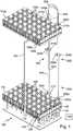
- Fig. 1shows a sample distribution system 100. This has a lower transport surface 110 and an upper transport surface 110a.
- the lower transport surface 110corresponds to a lower level of the sample distribution system 100.
- the upper transport surface 110 acorresponds to an upper level of the sample distribution system 100.
- the sample carrier 140has a magnetically active element in the form of a permanent magnet, so that by suitable actuation of the electromagnets 120, 120a, a force is exerted on the lower transport surface 110 in the present case by a sample carrier 140 with a sample container received therein Sample carrier 140 can be exercised and this can thus be moved over the lower transport surface 110 or the upper transport surface 110 a.
- the upper transport surfaceis held by means of a number of supports 105 above the lower transport surface 110, wherein in the present example only a single support 105 is shown.
- the sample distribution system 100further comprises a vertical conveyor 200, which serves to transport sample carriers 140 with sample tubes 145 received therein bidirectionally between the lower transport surface 110 and the upper transport surface 110a.
- the sample distribution system 100further includes a controller 150 configured to control the solenoids 120, 120 a and the vertical conveyor 200.
- the control device 150is capable of moving a sample carrier 140 over the lower transport surface 110 or the upper transport surface 110a by suitable driving of the magnets 120, 120a.
- the vertical conveyor device 200has a total of six conveying surfaces 210a, 210b, 210c, 210d, 210e, 210f. Below a respective conveying surface 210a, 210b, 210c, 210d, 210e, 210f, in each case an electromagnetic (conveying surface) actuator in the form of an electromagnet 220a, 220b, 220c, 220d, 220e, 220f is arranged.
- the sample carrier 140can be moved or pulled onto the respective conveying surface 210a, 210b, 210c, 210d, 210e, 210f and held by the conveying surface 210a, 210b , 210c, 210d, 210e, 210f are moved onto one of the transport surfaces 110, 110a or are encountered.
- the electromagnets 220a, 220b, 220c, 220d, 220e, 220fare also controllable by the control device 150.
- a respective conveying surface 210a, 210b, 210c, 210d, 210e, 210f and a respective electromagnet 220a, 220b, 220c, 220d, 220e, 220ftogether form a respective conveying element.
- the conveying surfaces 210a, 210b, 210c, 210d, 210e, 210fare arranged along a first band 240 and a second band 245.
- the two bands 240, 245define the position of the respective conveying surface 210a, 210b, 210c, 210d, 210e, 210f and ensure that a respective conveying surface 210a, 210b, 210c, 210d, 210e, 210f is horizontally aligned and remains.
- the first band 240passes over a first upper wheel 230.
- the second band 245passes over a second upper wheel 235.
- the bands 240, 245also pass over corresponding first and second lower wheels, which, however, in Fig. 1 not to be seen.
- the belts 240, 245 together with the wheels 230, 235form a circulation device.
- the conveying surfaces 210a, 210b, 210c, 210d, 210e, 210fare arranged along the belts 240, 245 at regular intervals.
- the conveying surfaces 210a, 210b, 210c, 210d, 210e, 210fcan be circulated.
- the drive of the upper wheels 230, 235is controllable by the control device 150, so that the control device 150 can use the vertical conveyor 200 for transporting sample carriers 140 with sample tube 145 accommodated between the lower transport surface 110 and the upper transport surface 110a.
- the transport surfaces 210a, 210c, 210d and 210fare each arranged such that they form a planar extension of the lower transport surface 110 and the upper transport surface 110a.
- This statecan be used to move a sample carrier 140 onto the respective transport surface 210a, 210c, 210d, 210f.
- the transport device 200can be set in motion so that the sample carrier 140 is transported to the other of the two transport surfaces 110, 110a. There it can be moved by means of the electromagnets 120, 120a, 220a, 220b, 220c, 220d, 220e, 220f onto the respective transport surface 110, 110a.
- the transport between the transport surfaces 110, 110aextends along a first vertical section 250 from the lower transport surface 110 to the upper transport surface 110a. It also extends along a second vertical section 255 parallel thereto from the upper transport surface 110a to the lower transport surface 110.
- the described embodiment of a vertical conveyor device 200enables a simple, reliable and space-saving bidirectional transport of sample carriers 140 with sample tube 145 accommodated between the lower transport surface 110 and the upper transport surface 110a. Due to the possible almost continuous operation of the vertical conveyor device 200, a high throughput is possible.
- the sample distribution system 100is part of a laboratory automation system having a number of non-illustrated pre-analytical, analytical and post-analytical stations located adjacent the transport surfaces 110 and / or 110a.
- the sample distribution system 100serves to transport the sample containers between these stations.
Landscapes
- Physics & Mathematics (AREA)
- Health & Medical Sciences (AREA)
- Life Sciences & Earth Sciences (AREA)
- Chemical & Material Sciences (AREA)
- Analytical Chemistry (AREA)
- Biochemistry (AREA)
- General Health & Medical Sciences (AREA)
- General Physics & Mathematics (AREA)
- Immunology (AREA)
- Pathology (AREA)
- Engineering & Computer Science (AREA)
- Civil Engineering (AREA)
- Mechanical Engineering (AREA)
- Structural Engineering (AREA)
- Automatic Analysis And Handling Materials Therefor (AREA)
- Non-Mechanical Conveyors (AREA)
- Belt Conveyors (AREA)
Description
Translated fromGermanDie Erfindung betrifft eine Vertikalfördervorrichtung zum Transport von in jeweiligen Probenträgern aufgenommenen Probenbehältern, ein Probenverteilungssystem mit einer solchen Vertikalfördervorrichtung und ein Laborautomatisierungssystem mit einem solchen Probenverteilungssystem.The invention relates to a vertical conveyor device for transporting sample containers accommodated in respective sample carriers, a sample distribution system comprising such a vertical conveyor device and a laboratory automation system having such a sample distribution system.
Probenbehälter sind typischerweise längliche, einseitig offene Gefäße aus meist transparentem Glas oder Kunststoff, die zur Aufbewahrung und zum Transport von meist flüssigen Proben verwendet werden. Bei derartigen Proben handelt es sich beispielsweise um Blutproben.Sample containers are typically elongated, unilaterally open vessels made of usually transparent glass or plastic, which are used for storage and transport of mostly liquid samples. Such samples are, for example, blood samples.
Probenverteilungssysteme werden beispielsweise in Laborautomatisierungssystemen verwendet, um Proben in Probenbehältern zu einer Mehrzahl von unterschiedlichen Stationen des Laborautomatisierungssystems zu transportieren.Sample distribution systems are used, for example, in laboratory automation systems to transport samples in sample containers to a plurality of different stations of the laboratory automation system.
Das Dokument
Die
Die
Die
Es ist eine Aufgabe der Erfindung, eine Vertikalfördervorrichtung vorzusehen, mit welcher Probenträger zwischen unterschiedlichen Niveaus eines Probenverteilungssystems transportiert werden können. Es ist des Weiteren eine Aufgabe der Erfindung, ein Probenverteilungssystem mit einer solchen Vertikalfördervorrichtung vorzusehen. Außerdem ist es eine Aufgabe der Erfindung, ein Laborautomatisierungssystem mit einem solchem Probenverteilungssystem vorzusehen.It is an object of the invention to provide a vertical conveyor device with which sample carriers can be transported between different levels of a sample distribution system. It is a further object of the invention to provide a sample distribution system with such a vertical conveyor. In addition, it is an object of the invention to provide a laboratory automation system having such a sample distribution system.
Dies wird erfindungsgemäß durch eine Vertikalfördervorrichtung nach Anspruch 1, ein Probenverteilungssystem nach Anspruch 7 und ein Laborautomatisierungssystem nach Anspruch 8 gelöst. Ausführungsformen können beispielsweise den Unteransprüchen entnommen werden.This is achieved according to the invention by a vertical conveyor device according to claim 1, a sample distribution system according to claim 7 and a laboratory automation system according to claim 8. Embodiments may, for example, be taken from the subclaims.
Die Erfindung betrifft eine Vertikalfördervorrichtung zum Transport von in Probenträgern aufgenommenen Probenbehältern zwischen einem unteren Niveau und einem oberen Niveau eines Probenverteilungssystems. Probenträger, die nicht Bestandteil der Vertikalfördervorrichtung sind, weisen mindestens ein magnetisch wirksames Element auf, das dazu ausgebildet ist, mit einem mittels mindestens eines elektromagnetischen Aktuators erzeugten Magnetfeld derart wechselzuwirken, dass eine Antriebskraft auf den Probenträger bewirkt wird.The invention relates to a vertical conveyor for transporting sample containers received in sample carriers between a lower level and an upper level of a sample distribution system. Sample carriers which are not part of the vertical conveyor device have at least one magnetically active element which is designed to interact with a magnetic field generated by means of at least one electromagnetic actuator in such a way that a driving force is effected on the sample carrier.
Die Vertikalfördervorrichtung weist auf:
- eine Anzahl von Förderelementen, die jeweils eine Förderfläche aufweisen, die zur Aufnahme oder zum Aufsetzen und Tragen mindestens eines Probenträgers vorgesehen ist,
- eine Umlaufeinrichtung, die dazu ausgebildet ist, im Betrieb die Förderelemente zwischen dem unteren Niveau und dem oberen Niveau umlaufend zu bewegen, wobei die jeweiligen Förderflächen während der umlaufenden Bewegung durchgängig horizontal ausgerichtet sind bzw. bleiben, und
- mindestens einen elektromagnetischen Aktuator, der auch als Förderflächenaktuator bezeichnet werden kann und der dazu ausgebildet ist, einen Probenträger, der sich auf einer der Förderflächen befindet, mit einer Antriebskraft zu beaufschlagen.
- a number of conveying elements, each having a conveying surface, which is provided for receiving or for placing and carrying at least one sample carrier,
- a circulation device, which is designed to move during operation, the conveying elements between the lower level and the upper level to move circumferentially, wherein the respective conveying surfaces during the circulating movement are continuously aligned horizontally or, and
- at least one electromagnetic actuator, which may also be referred to as Förderflächenaktuator and which is adapted to apply a sample carrier, which is located on one of the conveying surfaces with a driving force.
Die Vertikalfördervorrichtung ermöglicht einen Transport von Probenträgern mit darin aufgenommenen Probenbehältern zwischen unterschiedlichen Niveaus eines Probenverteilungssystems mit geringem Platzbedarf. Der Transport erfolgt vertikal, so dass während des Transports keine horizontale Distanz zu überwinden ist. Dies ermöglicht einen besonders kompakten Aufbau der Vertikalfördervorrichtung und eines sie enthaltenden Probenverteilungssystems.The vertical conveyor allows transport of sample carriers with sample containers received therein between different levels of a sample distribution system with a small footprint. The transport is vertical so that there is no horizontal distance to overcome during transport. This allows a particularly compact construction of the vertical conveyor and a sample distribution system containing them.
Probenträger sind typischerweise (nicht notwendigerweise) rund ausgebildet und mit einem magnetisch wirksamen Element in Form eines Permanentmagneten versehen. Sie weisen typischerweise an ihrer Oberseite eine Haltevorrichtung auf, um ein Probenröhrchen aufzunehmen, die beispielsweise ähnlich einem Reagenzglas oder als Reagenzglas ausgebildet sein können. Probenträger können beispielsweise zum Transportieren des Probenbehälters zwischen präanalytischen, analytischen und/oder postanalytischen Stationen eines Laborautomatisierungssystems verwendet werden. Eine präanalytische Station dient üblicherweise der Vorbereitung von Proben bzw. Probenbehältern. Eine analytische Station kann beispielsweise dazu ausgebildet sein, eine Probe oder einen Teil der Probe und eine Reagenz zu verwenden, um ein messbares Signal zu erzeugen, auf Basis dessen bestimmbar ist, ob und gegebenenfalls in welcher Konzentration der Analyt vorhanden ist. Eine postanalytische Station dient üblicherweise der Nachverarbeitung von Proben bzw. Probenbehältern.Sample carriers are typically (not necessarily) round and provided with a magnetically active element in the form of a permanent magnet. They typically have at their top a holding device to receive a sample tube, which may be formed, for example, similar to a test tube or test tube. Sample carriers may be used, for example, to transport the sample container between preanalytical, analytical and / or post-analytical stations of a laboratory automation system. A preanalytical station usually serves to prepare samples or sample containers. An analytical station may, for example, be designed to use a sample or a portion of the sample and a reagent to generate a measurable signal on the basis of which it is possible to determine whether and, if appropriate, in what concentration the analyte is present. A post-analytical station usually serves the post-processing of samples or sample containers.
Die Förderelemente der Vertikalfördervorrichtung ermöglichen aufgrund ihrer kontinuierlich horizontalen Ausrichtung, dass ein Probenträger auf die Förderfläche verbracht und dort transportiert werden kann, ohne herunterzufallen bzw. von der Förderfläche zu kippen. Es sei verstanden, dass grundsätzlich auch mehrere Probenträger auf eine einzelne Förderfläche verbracht werden können.Due to their continuous horizontal alignment, the conveying elements of the vertical conveying device allow a sample carrier to be transported onto the conveying surface and transported there without falling off or tilting off the conveying surface. It should be understood that basically also several sample carriers can be placed on a single conveyor surface.
Die Förderelemente mit ihren jeweiligen Förderflächen können in der Art eines Paternosters ausgeführt sein.The conveying elements with their respective conveying surfaces can be designed in the manner of a paternoster.
Der elektromagnetische (Förderflächen-) Aktuator, bevorzugt ein Elektromagnet, ist gemäß einer Ausführung derart ausgeführt, dass er mit der zugehörigen Förderfläche, unter der er angeordnet ist, umläuft. Typischerweise wird in einer solchen Ausführung unter jeder Förderfläche ein zugehöriger elektromagnetischer (Förderflächen-) Aktuator angeordnet. Alternativ kann auch ein einzelner ortsfester elektromagnetischer (Förderflächen-) Aktuator verwendet werden, der beispielsweise schwenkbar ausgeführt sein kann und dann unter eine Förderfläche geschwenkt wird, wenn die Förderfläche beladen und/oder entladen werden soll.The electromagnetic (conveyor) actuator, preferably an electromagnet, is designed according to an embodiment such that it rotates with the associated conveying surface under which it is arranged. Typically, in such an embodiment, under each conveying surface, an associated electromagnetic (conveying surface) actuator is disposed. Alternatively, it is also possible to use a single stationary electromagnetic (conveying surface) actuator which, for example, can be designed to be pivotable and then pivoted under a conveying surface when the conveying surface is to be loaded and / or unloaded.
Es sei verstanden, dass zum Verbringen von Probenträgern auf die Transportfläche anstelle von elektromagnetischen (Förderflächen-) Aktuatoren auch andere Mechanismen verwendet werden können. Insbesondere kann beispielsweise ein Greifer, ein Schleppriemen oder eine andere Konstruktion verwendet werden. Derartige Abwandlungen der beschriebenen Ausführung stellen eigenständige Erfindungsgedanken dar, wobei die weiter oben und unten beschriebenen Abwandlungen auf diese entsprechend angewendet werden können, soweit sie mit der entsprechenden Ausführung kompatibel sind.It should be understood that other mechanisms can be used to accommodate sample carriers on the transport surface instead of electromagnetic (conveying surface) actuators. In particular, for example, a gripper, a tow belt or other construction may be used. Such modifications of the described embodiment represent independent inventive concept, wherein the modifications described above and below can be applied to them accordingly, as far as they are compatible with the corresponding embodiment.
Bei einem elektromagnetischen (Förderflächen-) Aktuator kann es sich insbesondere um einen Elektromagneten, bevorzugt um einen spulenförmigen Elektromagneten mit einem Kern, handeln.An electromagnetic (conveying surface) actuator may, in particular, be an electromagnet, preferably a coil-shaped electromagnet with a core.
Mittels eines elektromagnetischen (Förderflächen-) Aktuators kann ein Probenträger auf die Förderfläche verbracht werden, auf dieser gehalten werden und/oder von dieser entfernt werden. Dies ermöglicht eine besonders einfache Handhabung des Probenträgers, wobei auf komplizierte Vorrichtungen wie beispielsweise Greifer oder Ähnliches verzichtet werden kann.By means of an electromagnetic (conveying surface) actuator, a sample carrier can be brought onto the conveying surface, be held on this and / or removed therefrom. This allows a particularly simple handling of the sample carrier, which can be dispensed with complicated devices such as grippers or the like.
Die Umlaufeinrichtung kann im Betrieb die Förderelemente entlang eines von allen Förderelementen beschriebenen Umlaufwegs bewegen. Dies entspricht prinzipiell der Ausführung eines Paternosters. Damit kann ein nahezu kontinuierlicher Transport zwischen unterschiedlichen Niveaus erreicht werden.During operation, the circulation device can move the conveying elements along a circulation path described by all conveying elements. This corresponds in principle to the design of a paternoster. Thus, a nearly continuous transport between different levels can be achieved.
Die Vertikalfördervorrichtung kann eine Mehrzahl von Förderelementen aufweisen, die entlang des Umlaufwegs in gleichmäßigen Abständen zueinander angeordnet sind. Damit kann die Handhabung der Vertikalfördervorrichtung vereinfacht werden. Es kann beispielsweise davon ausgegangen werden, dass nach einem definierten Betrieb der Vertikalfördervorrichtung, beispielsweise für einen bestimmten Zeitraum, ein Transportvorgang abgeschlossen ist. Entsprechend steht wieder eine Förderfläche für einen Transportvorgang zur Verfügung. Ein Abstand zwischen benachbarten Förderelementen sollte mindestens so groß sein, dass ein Probenträger mit aufgenommenem Behälter zwischen zwei Förderflächen bewegbar ist. Es kann vorteilhaft sein, wenn gewisse Förderflächen zu gewissen Förderflächen eine bestimmte Proportion aufweisen, um eben gleichzeitig oben und unten aufladen zu können.The vertical conveyor may comprise a plurality of conveying elements which are arranged along the circulation path at regular intervals from each other. Thus, the handling of the vertical conveyor can be simplified. It can be assumed, for example, that after a defined operation of the vertical conveyor device, for example for a certain period of time, a transport process is completed. Accordingly, again a conveying surface is available for a transport process. A distance between adjacent conveying elements should be at least so large that a sample carrier with a container received between two conveying surfaces is movable. It can be advantageous if certain conveying surfaces to certain conveying surfaces have a certain proportion in order to be able to charge at the same time above and below.
Der Umlaufweg kann einen ersten vertikalen Abschnitt und einen dazu parallelen zweiten vertikalen Abschnitt aufweisen, die jeweils zwischen dem unteren Niveau und dem oberen Niveau verlaufen. Die Umlaufeinrichtung bewegt im Betrieb die Förderelemente entlang des ersten vertikalen Abschnitts von dem unteren Niveau zu dem oberen Niveau und bewegt ferner die Förderelemente entlang des zweiten vertikalen Abschnitts von dem oberen Niveau zu dem unteren Niveau. Damit ist festgelegt, an welchen Stellen ein Transport von oben nach unten und an welchen Stellen ein Transport von unten nach oben erfolgt.The circulation path may include a first vertical portion and a second vertical portion parallel thereto, each extending between the lower level and the upper level. The circulating means, in operation, moves the conveying elements along the first vertical section from the lower level to the upper level and further moves the conveying elements along the second vertical section from the upper level to the lower level. This determines at which points a transport from top to bottom and at which points a transport from bottom to top takes place.
Die Umlaufeinrichtung kann ein erstes oberes Rad, ein erstes unteres Rad und ein erstes Band aufweisen, wobei das erste Band um das erste obere Rad und das erste untere Rad jeweils halbkreisförmig umläuft und zwischen dem ersten oberen Rad und dem ersten unteren Rad gespannt ist, wobei zumindest das erste obere Rad oder das erste untere Rad im Betrieb der Umlaufeinrichtung angetrieben wird, und wobei die Förderelemente an dem ersten Band befestigt sind. Die Umlaufeinrichtung kann ein zweites oberes Rad, ein zweites unteres Rad und ein zweites Band aufweisen, wobei das zweite Band um das zweite obere Rad und das zweite untere Rad jeweils halbkreisförmig umläuft und zwischen dem zweiten oberen Rad und dem zweiten unteren Rad gespannt ist, wobei zumindest das zweite obere Rad oder das zweite untere Rad im Betrieb der Umlaufeinrichtung synchron mit dem ersten oberen Rad oder dem ersten unteren Rad angetrieben ist, und wobei die Förderelemente an dem ersten Band und an dem zweiten Band befestigt sind. Dies ermöglicht eine einfache Realisierung der bereits beschriebenen Ausführung mit einem Umlauf der Förderelemente entlang jeweiliger vertikaler Abschnitte.The circulating means may include a first upper wheel, a first lower wheel, and a first band, wherein the first band is respectively semicircular around the first upper wheel and the first lower wheel and is stretched between the first upper wheel and the first lower wheel at least the first upper wheel or the first lower wheel in operation of Circulating device is driven, and wherein the conveying elements are attached to the first band. The circulating means may comprise a second upper wheel, a second lower wheel and a second band, the second band respectively circulating around the second upper wheel and the second lower wheel in a semicircle and being stretched between the second upper wheel and the second lower wheel at least the second upper wheel or the second lower wheel is driven synchronously with the first upper wheel or the first lower wheel in operation of the revolving device, and wherein the conveying elements are fixed to the first band and to the second band. This allows a simple realization of the already described embodiment with a circulation of the conveying elements along respective vertical sections.
Ein jeweiliges Förderelement kann eine Erkennungsvorrichtung für einen auf der Förderfläche des Förderelements befindlichen Probenträger aufweisen. Damit kann im Betrieb der Vertikalfördervorrichtung erkannt werden, ob sich ein Probenträger auf der jeweiligen Förderfläche befindet und somit kann die Zuverlässigkeit im Betrieb erhöht werden. Eine solche Erkennungsvorrichtung kann als Hall-Sensor ausgebildet sein.A respective conveying element may have a recognition device for a sample carrier located on the conveying surface of the conveying element. Thus, it can be detected in operation of the vertical conveyor, whether a sample carrier is located on the respective conveying surface and thus the reliability can be increased during operation. Such a recognition device can be designed as a Hall sensor.
Die Erfindung betrifft des Weiteren ein Probenverteilungssystem, aufweisend:
- eine Anzahl von Probenträgern zur Aufnahme eines oder mehrerer Probenbehälter, wobei ein jeweiliger Probenträger mindestens ein magnetisch wirksames Element aufweist, das dazu ausgebildet ist, mit einem mittels mindestens eines elektromagnetischen Aktuators erzeugten Magnetfeld derart wechselzuwirken, dass eine Antriebskraft auf den Probenträger bewirkt wird,
- eine untere Transportfläche und eine dazu vertikal höher angeordnete obere Transportfläche, die jeweils dazu ausgebildet sind, Probenträger zu tragen,
- eine Anzahl von ersten elektromagnetischen Aktuatoren, die auch als Transportflächenaktuatoren bezeichnet werden können und die stationär unter der unteren Transportfläche angeordnet sind, wobei die ersten elektromagnetischen (Transportflächen-) Aktuatoren dazu ausgebildet sind, einen Probenträger, der auf der unteren Transportfläche angeordnet ist, durch Ausüben einer magnetischen Kraft auf den Probenträger zu bewegen, und
- eine Anzahl von zweiten elektromagnetischen Aktuatoren, die auch als Transportflächenaktuatoren bezeichnet werden können und die stationär unter der oberen Transportfläche angeordnet sind, wobei die zweiten elektromagnetischen (Transportflächen-) Aktuatoren dazu ausgebildet sind, einen Probenträger, der auf der oberen Transportfläche angeordnet ist, durch Ausüben einer magnetischen Kraft auf den Probenträger zu bewegen,
- eine oben beschriebene Vertikalfördervorrichtung, wobei die untere Transportfläche dem unteren Niveau entspricht und die obere Transportfläche dem oberen Niveau entspricht, sowie
- eine Steuerungseinrichtung, die dazu ausgebildet ist,
- die unter den Transportflächen angeordneten elektromagnetischen (Transportflächen-) Aktuatoren derart anzusteuern, dass sich ein Probenträger auf den Transportflächen entlang einer zugehörigen vorgebbaren Bewegungsbahn bewegt,
- den mindestens einen elektromagnetischen (Förderflächen-) Aktuator und/oder die unter den Transportflächen angeordneten elektromagnetischen (Förderflächen-) Aktuatoren derart anzusteuern, dass ein Probenträger von der Transportfläche in Richtung einer der Förderflächen oder von einer der Förderflächen in Richtung einer der Transportflächen bewegt wird, und
- das Umlaufsystem so zu steuern, dass die Probenträger zwischen dem unteren Niveau und dem oberen Niveau transportiert werden.
- a number of sample carriers for holding one or more sample containers, wherein a respective sample carrier has at least one magnetically active element which is designed to interact with a magnetic field generated by at least one electromagnetic actuator in such a way that a drive force is caused on the sample carrier,
- a lower transport surface and a vertically higher arranged upper transport surface, which are each designed to carry sample carriers,
- a number of first electromagnetic actuators, which may also be referred to as Transportflächenaktuatoren and which are arranged stationary under the lower transport surface, wherein the first electromagnetic (transport surface) actuators are adapted to a sample carrier, which is arranged on the lower transport surface by exercising to move a magnetic force on the sample carrier, and
- a number of second electromagnetic actuators, which may also be referred to as Transportflächenaktuatoren and which are arranged stationary under the upper transport surface, wherein the second electromagnetic (transport surface) actuators are adapted to a sample carrier, which is arranged on the upper transport surface by exercising to move a magnetic force on the sample carrier,
- a vertical conveyor described above, wherein the lower transport surface corresponds to the lower level and the upper transport surface corresponds to the upper level, and
- a control device designed to
- to actuate the electromagnetic (transport surface) actuators arranged under the transport surfaces such that a sample carrier moves on the transport surfaces along an associated predeterminable movement path,
- the at least one electromagnetic (conveying surface) actuator and / or the electromagnetic (conveying surface) actuators arranged under the transport surfaces such that a sample carrier is moved by the transport surface in the direction of one of the conveying surfaces or by one of the conveying surfaces in the direction of one of the transport surfaces, and
- To control the circulation system so that the sample carriers are transported between the lower level and the upper level.
Die Probenträger können rund ausgeführt sein, was eine zu beachtende Vorzugsorientierung vermeidet. Bei einem magnetisch wirksamen Element in einem Probenträger kann es sich um einen Permanentmagneten oder ein anderes magnetisches Material handeln.The sample carriers can be made round, which avoids a preferred orientation to be observed. A magnetically active element in a sample carrier may be a permanent magnet or another magnetic material.
Die obere Transportfläche ist in vertikaler Richtung höher angeordnet als die untere Transportfläche. Dies kann beispielsweise dazu dienen, Analysegeräte oder andere Einrichtungen operativ mit dem Probenverteilungssystem zu koppeln, deren Ein- und/oder Auslass sich auf unterschiedlichen Höhen befindet. Zudem ist es möglich, unterschiedliche Niveaus zu verwenden, um unterschiedliche Transportaufgaben auszuführen. Beispielsweise kann ein unteres Niveau zum Transport von Probenträgern über längere Strecken verwendet werden, wohingegen ein oberes Niveau zum Verbringen der Probenträger an Analysegeräte oder andere Stationen verwendet wird. Es sei verstanden, dass beispielsweise auch der umgekehrte Fall möglich ist.The upper transport surface is arranged higher in the vertical direction than the lower transport surface. This may serve, for example, to operatively couple analyzers or other devices to the sample distribution system whose inlet and / or outlet is at different heights. In addition, it is possible to use different levels to perform different transport tasks. For example, a lower level may be used to transport sample carriers over longer distances, whereas an upper level may be used to move the sample carriers to analyzers or other stations. It should be understood that, for example, the reverse case is possible.
Bei den elektromagnetischen Aktuatoren kann es sich um Elektromagnete handeln, beispielsweise in Form von Spulen. Diese können einen Kern aufweisen, der die magnetische Wirkung verstärkt. Durch Wechselwirkung zwischen einem durch die elektromagnetischen Aktuatoren erzeugten Magnetfeld und dem magnetisch wirksamen Element in dem Probenträger kann ein Probenträger über die Transportfläche bewegt werden. Hierzu können die elektromagnetischen Aktuatoren in geeigneter Weise angesteuert werden. Die elektromagnetischen Aktuatoren können matrixartig verteilt sein, so dass eine zweidimensionale Bewegung über die Transportfläche bewirkt werden kann.The electromagnetic actuators may be electromagnets, for example in the form of coils. These may have a core that enhances the magnetic effect. By interaction between a magnetic field generated by the electromagnetic actuators and the magnetically active element in the sample carrier, a sample carrier can be moved over the transport surface. For this purpose, the electromagnetic actuators can be controlled in a suitable manner. The electromagnetic actuators can be distributed like a matrix, so that a two-dimensional movement over the transport surface can be effected.
Mittels der Vertikalfördervorrichtung können Probenträger mit darin aufgenommenen Probenbehältern zwischen dem unteren Niveau und dem oberen Niveau transportiert werden. Es sei verstanden, dass ein Probenverteilungssystem auch mehr als zwei Niveaus, beispielsweise drei oder vier Niveaus, aufweisen kann. Damit kann die Flexibilität weiter erhöht werden. Die erfindungsgemäße Vertikalfördervorrichtung ist an derartige Ausführungen problemlos anpassbar.By means of the vertical conveyor, sample carriers with sample containers received therein can be transported between the lower level and the upper level. It should be understood that a sample distribution system may also have more than two levels, for example, three or four levels. Thus, the flexibility can be further increased. The vertical conveyor according to the invention can be easily adapted to such designs.
Die Steuerungseinrichtung kann beispielsweise als Computer, als Mikrocomputer, als Mikroprozessor, als speicherprogrammierbare Steuerung (SPS), als anwendungsspezifischer integrierter Schaltkreis (ASIC) oder in anderer Weise ausgeführt werden. Beispielsweise kann sie Prozessormittel und Speichermittel aufweisen, wobei in den Speichermitteln Code gespeichert ist, bei dessen Ausführung sich die Prozessormittel in definierter Weise verhalten. Bei einem Probenträger, der von der Transportfläche in Richtung der Förderfläche bewegt wird, handelt es sich typischerweise um einen zu befördernden Probenträger. Dieser soll also mittels der Vertikalfördervorrichtung auf ein anderes Niveau verbracht werden. Bei einem Probenträger, welcher in bezeichneter Weise von der Förderfläche in Richtung der Transportfläche bewegt wird, handelt es sich typischerweise um einen beförderten Probenträger, welcher also von einem anderen Niveau durch die Vertikalfördervorrichtung auf das aktuelle Niveau transportiert wurde und nun auf die Transportfläche des entsprechenden Niveaus bewegt werden soll.The controller may be implemented, for example, as a computer, a microcomputer, a microprocessor, a programmable logic controller (PLC), an application specific integrated circuit (ASIC), or otherwise. For example, it may comprise processor means and storage means, wherein the storage means stores code in the execution of which the processor means behave in a defined way. In a sample carrier, which is moved by the transport surface in the direction of the conveying surface, it is typically a sample carrier to be transported. This should therefore be spent by means of the vertical conveyor to another level. In the case of a sample carrier which is moved in a designated manner from the conveying surface in the direction of the transport surface, it is typically a transported sample carrier, which has thus been transported from another level through the vertical conveying device to the current level and now onto the transport surface of the corresponding level to be moved.
Die Steuerungseinrichtung kann dazu ausgebildet sein, einen Transport eines Probenträgers von der unteren Transportfläche zu der oberen Transportfläche zu bewirken, indem sie
- die Umlaufeinrichtung der Vertikalfördervorrichtung so lange betreibt, bis sich eines der Förderelemente in einer Position befindet, in der die Förderfläche dieses Förderelements eine ebene Erweiterung der unteren Transportfläche bildet,
- den Probenträger mittels der ersten elektromagnetischen (Transportflächen-) Aktuatoren zu dem Förderelement bewegt,
- den Probenträger mittels (oder unter Mitwirkung) des oder der (Förderflächen-) Aktuatoren auf die Förderfläche des Förderelements bewegt,
- die Umlaufeinrichtung der Vertikalfördervorrichtung so lange betreibt, bis sich das Förderelement in einer Position befindet, in welcher die Förderfläche eine ebene Erweiterung der oberen Transportfläche bildet, und
- den Probenträger mittels (oder unter Mitwirkung) des oder der (Förderflächen-) Aktuatoren von der Förderfläche auf die obere Transportfläche bewegt.
- the circulation device of the vertical conveying device operates until one of the conveying elements is in a position in which the conveying surface of this conveying element forms a planar extension of the lower conveying surface,
- moves the sample carrier to the conveyor element by means of the first electromagnetic (transport surface) actuators,
- the sample carrier is moved onto the conveying surface of the conveying element by means of (or with the cooperation of) the or the (conveying surface) actuators,
- the circulation device of the vertical conveyor operates until the conveyor element is in a position in which the conveyor surface forms a planar extension of the upper conveyor surface, and
- moves the sample carrier by means of (or in cooperation with) the or the (conveying surface) actuators from the conveying surface to the upper transport surface.
Die Steuerungseinrichtung kann dazu ausbildet sein, einen Transport eines Probenträgers von der oberen Transportfläche zu der unteren Transportfläche zu bewirken, indem sie
- die Umlaufeinrichtung der Vertikalfördervorrichtung so lange betreibt, bis sich eines der Förderelemente in einer Position befindet, in welcher die Förderfläche des Förderelements eine ebene Erweiterung der oberen Transportfläche bildet,
- den Probenträger mittels der zweiten elektromagnetischen (Transportflächen-) Aktuatoren zu dem Förderelement bewegt,
- den Probenträger mittels (oder unter Mitwirkung) des oder der (Förderflächen-) Aktuatoren auf die Förderfläche des Förderelements bewegt,
- die Umlaufeinrichtung der Vertikalfördervorrichtung so lange betreibt, bis sich das Förderelement in einer Position befindet, in welcher die Förderfläche des Förderelements eine ebene Erweiterung der unteren Transportfläche bildet, und
- den Probenträger mittels (oder unter Mitwirkung) des oder der (Förderflächen-) Aktuatoren von der Förderfläche auf die untere Transportfläche bewegt.
- the circulation device of the vertical conveyor operates until one of the conveyor elements is in a position in which the conveying surface of the conveyor element forms a planar extension of the upper conveyor surface,
- moves the sample carrier to the conveying element by means of the second electromagnetic (transport surface) actuators,
- the sample carrier is moved onto the conveying surface of the conveying element by means of (or with the cooperation of) the or the (conveying surface) actuators,
- the circulation device of the vertical conveyor operates until the conveyor element is in a position in which the conveying surface of the conveyor element forms a planar extension of the lower conveyor surface, and
- moves the sample carrier by means of (or in cooperation with) the or the (conveying surface) actuators from the conveying surface to the lower transport surface.
Die beschriebenen Ausführungen der Steuerungseinrichtung ermöglichen einen Transport von Probenträgern zwischen dem oberen und dem unteren Niveau. Die Steuerungseinrichtung kann dazu ausgebildet sein, dass sie sowohl einen Probenträger von der unteren Transportfläche auf die obere Transportfläche wie auch einen Probenträger von der oberen Transportfläche auf die untere Transportfläche in eben beschriebener Weise verbringen kann.The described embodiments of the control device allow a transport of sample carriers between the upper and the lower level. The control device can be configured to be able to transfer both a sample carrier from the lower transport surface to the upper transport surface and a sample carrier from the upper transport surface to the lower transport surface in the manner just described.
Die Steuerungseinrichtung kann dazu ausgebildet sein, den Probenträger auch mittels des (Förderflächen-) Aktuators auf die obere bzw. untere Transportfläche zu bewegen. Dies insbesondere dann, wenn ein Probenträger zu der entsprechenden Transportfläche transportiert wurde und nunmehr auf die Transportfläche bewegt werden soll. Auf diese Weise kann beispielsweise eine abstoßende Kraft auf den Probenträger ausgeübt werden.The control device can be designed to also move the sample carrier to the upper or lower transport surface by means of the (conveying surface) actuator. This is especially true when a sample carrier has been transported to the corresponding transport surface and is now to be moved onto the transport surface. In this way, for example, a repulsive force can be exerted on the sample carrier.
Die untere Transportfläche und die obere Transportfläche können in logische Felder unterteilt sein, wobei jedes logische Feld jeweils einem elektromagnetischen Aktuator aus der Anzahl von ersten bzw. zweiten elektromagnetischen Aktuatoren zugeordnet ist. Weiter kann jede Förderfläche der Vertikalfördervorrichtung ein weiteres logisches Feld bilden. Die Steuerungseinrichtung kann ein jeweiliges von einer Förderfläche gebildetes logisches Feld als logisches Feld einer der Transportflächen handhaben, wenn die Förderfläche eine ebene Erweiterung der jeweiligen Transportfläche bildet. Dies ermöglicht eine besonders einfache Ansteuerung der elektromagnetischen Aktuatoren durch die Steuerungseinrichtung. Wenn eine Förderfläche eine ebene Erweiterung der jeweiligen Transportfläche bildet, muss nicht mehr zwischen logischen Feldern der Transportfläche und der Förderfläche unterschieden werden.The lower transport surface and the upper transport surface may be subdivided into logical fields, wherein each logical field is assigned in each case to an electromagnetic actuator of the number of first and second electromagnetic actuators. Furthermore, each conveying surface of the vertical conveying device can form a further logical field. The control device can handle a respective logical field formed by a conveying surface as a logical field of one of the conveying surfaces when the conveying surface forms a planar extension of the respective conveying surface. This allows a particularly simple control of the electromagnetic actuators by the control device. If a conveying surface forms a flat extension of the respective transport surface, it is no longer necessary to distinguish between logical fields of the transport surface and the conveying surface.
Die Vertikalfördervorrichtung kann als optionales Modul einer Einheit ausgebildet sein, die die obere Transportfläche und die untere Transportfläche trägt. Dies ermöglicht eine einfache und zuverlässige Ausführung.The vertical conveyor may be formed as an optional module of a unit carrying the upper transport surface and the lower transport surface. This allows a simple and reliable execution.
Die Steuerungseinrichtung kann dazu ausgebildet sein, einen bidirektionalen Transport der Probenträger zwischen den Transportflächen mittels der Vertikalfördervorrichtung zu bewirken.The control device can be designed to effect bidirectional transport of the sample carriers between the transport surfaces by means of the vertical conveyor device.
Das Laborautomatisierungssystem weist eine Anzahl (beispielsweise zwischen zwei und zwanzig) von präanalytischen und/oder analytischen und/oder postanalytischen Stationen auf, die dazu ausgebildet sind, Probenbehälter und/oder Proben, die in den Probenbehältern enthalten sind, zu bearbeiten oder zu verarbeiten. Das Bearbeiten bzw. Verarbeiten kann beispielsweise ein Lesen eines Barcodes, ein Entfernen einer Kappe auf dem Röhrchen, ein Zentrifugieren der Probe, ein Aliquotieren der Probe, ein Analysieren der Probe usw. umfassen. Das Laborautomatisierungssystem weist weiter ein oben genanntes Probenverteilungssystem zum Transportieren der Probenbehälter zwischen den präanalytischen, analytischen und postanalytischen Stationen auf.The laboratory automation system has a number (e.g., between two and twenty) of preanalytical and / or analytical and / or post-analytical stations adapted to process or process sample containers and / or samples contained in the sample containers. The processing may include, for example, reading a barcode, removing a cap on the tube, centrifuging the sample, aliquoting the sample, analyzing the sample, and so on. The laboratory automation system further includes a sample distribution system as described above for transporting the sample containers between the preanalytical, analytical and post-analytical stations.
Die präanalytischen, analytischen und postanalytischen Stationen können beispielsweise mindestens eine Station aus der Menge folgender Stationen aufweisen: eine Kappenentfernungsstation zum Entfernen von Kappen bzw. Verschlüssen auf Probenröhrchen, eine Kappenaufbringstation zum Aufbringen von Kappen bzw. Verschlüssen auf Probenröhrchen, eine Aliquotierstation zum Aliquotieren von Proben, eine Zentrifugierstation zum Zentrifugieren von Proben, eine Archivierstation zum Archivieren von Proben, eine Pipettierstation zum Pipettieren, eine Sortierstation zum Sortieren von Proben bzw. Probenröhrchen, eine Probenröhrchentypbestimmungsstation zum Bestimmen eines Typs eines Probenröhrchens und eine Probenqualitätsbestimmungsstation zum Bestimmen einer Probenqualität.For example, the preanalytical, analytical and post-analytical stations may include at least one station among the following stations: a cap removal station for removing caps on sample tubes, a cap application station for applying caps to sample tubes, an aliquoting station for aliquoting samples, a centrifugation station for centrifuging samples, an archiving station for archiving samples, a pipetting station for pipetting, a sorting station for sorting samples, a sample tube type determining station for determining a type of sample tube, and a sample quality determination station for determining a sample quality.
Die Erfindung wird nachfolgend unter Bezugnahme auf die Zeichnung detailliert beschrieben. Hierbei zeigt schematisch:
- Fig. 1
- ein Probenverteilungssystem mit einer Vertikalfördervorrichtung.
- Fig. 1
- a sample distribution system with a vertical conveyor.
Unterhalb der unteren Transportfläche 110 ist eine Anzahl von ersten elektromagnetischen (Transportflächen-) Aktuatoren in Form von Spulen 120 mit jeweiligen Kernen 125 angeordnet. Unterhalb der oberen Transportfläche 110a ist entsprechend eine Anzahl von zweiten elektromagnetischen (Transportflächen-) Aktuatoren in Form von Spulen 120a mit jeweiligen Kernen 125a angeordnet. Auf der unteren Transportfläche 110 befindet sich vorliegend ein Probenträger 140 mit einem darin aufgenommenen Probenbehälter in Form eines Probenröhrchens 145. Der Probenträger 140 weist ein magnetisch wirksames Element in Form eines Permanentmagneten auf, so dass durch geeignete Ansteuerung der Elektromagnete 120, 120a eine Kraft auf den Probenträger 140 ausgeübt werden kann und dieser somit über die untere Transportfläche 110 oder die obere Transportfläche 110a bewegt werden kann.Below the
Die obere Transportfläche wird mittels einer Anzahl von Stützen 105 oberhalb der unteren Transportfläche 110 gehalten, wobei vorliegend exemplarisch lediglich eine einzelne Stütze 105 gezeigt ist.The upper transport surface is held by means of a number of
Das Probenverteilungssystem 100 weist ferner eine Vertikalfördervorrichtung 200 auf, die dazu dient, Probenträger 140 mit darin aufgenommenen Probenröhrchen 145 bidirektional zwischen der unteren Transportfläche 110 und der oberen Transportfläche 110a zu transportieren.The
Das Probenverteilungssystem 100 weist ferner eine Steuerungseinrichtung 150 auf, die dazu ausgebildet ist, die Elektromagnete 120, 120a und die Vertikalfördervorrichtung 200 zu steuern. Die Steuerungseinrichtung 150 ist dazu in der Lage, durch geeignetes Ansteuern der Magnete 120, 120a einen Probenträger 140 über die untere Transportfläche 110 oder die obere Transportfläche 110a zu bewegen.The
Die Vertikalfördervorrichtung 200 weist insgesamt sechs Förderflächen 210a, 210b, 210c, 210d, 210e, 210f auf. Unterhalb einer jeweiligen Förderfläche 210a, 210b, 210c, 210d, 210e, 210f ist jeweils ein elektromagnetischer (Förderflächen-) Aktuator in Form eines Elektromagneten 220a, 220b, 220c, 220d, 220e, 220f angeordnet. Mittels dieser Elektromagnete 220a, 220b, 220c, 220d, 220e, 220f kann der Probenträger 140 auf die jeweilige Förderfläche 210a, 210b, 210c, 210d, 210e, 210f bewegt bzw. gezogen werden, auf dieser gehalten werden und von der Förderfläche 210a, 210b, 210c, 210d, 210e, 210f auf eine der Transportflächen 110, 110a bewegt bzw. gestoßen werden. Die Elektromagnete 220a, 220b, 220c, 220d, 220e, 220f sind ebenfalls durch die Steuerungseinrichtung 150 ansteuerbar. Außerdem kann durch eine Induktionsmessung mittels der Elektromagnete 220a, 220b, 220c, 220d, 220e, 220f erkannt werden, ob sich ein Probenträger 140 auf der jeweiligen Förderfläche 210a, 210b, 210c, 210d, 210e, 210f befindet.The
Eine jeweilige Förderfläche 210a, 210b, 210c, 210d, 210e, 210f und ein jeweiliger Elektromagnet 220a, 220b, 220c, 220d, 220e, 220f bilden zusammen ein jeweiliges Förderelement.A respective conveying
Die Förderflächen 210a, 210b, 210c, 210d, 210e, 210f sind entlang eines ersten Bands 240 und eines zweiten Bands 245 angeordnet. Die beiden Bänder 240, 245 definieren dabei die Position der jeweiligen Förderfläche 210a, 210b, 210c, 210d, 210e, 210f und sorgen dafür, dass eine jeweilige Förderfläche 210a, 210b, 210c, 210d, 210e, 210f horizontal ausgerichtet ist und bleibt. Das erste Band 240 läuft über ein erstes oberes Rad 230 um. Das zweite Band 245 läuft über ein zweites oberes Rad 235 um. Die Bänder 240, 245 laufen auch über entsprechende erste und zweite untere Räder um, welche jedoch in
Die Förderflächen 210a, 210b, 210c, 210d, 210e, 210f sind entlang der Bänder 240, 245 in gleichmäßigen Abständen angeordnet. Mittels der oberen Räder 230, 235, welche beide antreibbar sind, können die Förderflächen 210a, 210b, 210c, 210d, 210e, 210f umlaufend bewegt werden. Der Antrieb der oberen Räder 230, 235 ist durch die Steuerungseinrichtung 150 steuerbar, so dass die Steuerungseinrichtung 150 die Vertikalfördervorrichtung 200 zum Transport von Probenträgern 140 mit darin aufgenommenem Probenröhrchen 145 zwischen der unteren Transportfläche 110 und der oberen Transportfläche 110a verwenden kann.The conveying
In dem in
Der Transport zwischen den Transportflächen 110, 110a verläuft dabei entlang eines ersten vertikalen Abschnitts 250 von der unteren Transportfläche 110 zur oberen Transportfläche 110a. Er verläuft des Weiteren entlang eines dazu parallelen zweiten vertikalen Abschnitts 255 von der oberen Transportfläche 110a zur unteren Transportfläche 110.The transport between the transport surfaces 110, 110a extends along a first
Die beschriebene Ausführung einer Vertikalfördervorrichtung 200 ermöglicht einen einfachen, zuverlässigen und platzsparenden bidirektionalen Transport von Probenträgern 140 mit darin aufgenommenem Probenröhrchen 145 zwischen der unteren Transportfläche 110 und der oberen Transportfläche 110a. Durch den möglichen nahezu kontinuierlichen Betrieb der Vertikalfördervorrichtung 200 ist ein hoher Durchsatz möglich.The described embodiment of a
Das Probenverteilungssystem 100 ist Bestandteil eines Laborautomatisierungssystems mit einer Anzahl von nicht näher dargestellten präanalytischen, analytischen und postanalytischen Stationen, die angrenzend an die Transportflächen 110 und/oder 110a angeordnet sind. Das Probenverteilungssystem 100 dient zum Transport der Probenbehälter zwischen diesen Stationen.The
Claims (8)
- Vertical conveying device (200) for transportation of sample containers (145) being received in respective sample carriers (140) between a bottom level and a top level of a sample distribution system (100),- wherein a respective sample carrier (140) comprises at least one magnetically active element, which is adapted to interact with a magnetic field, which is generated by means of at least one electromagnetic actuator (120, 120a, 220a, 220b, 220c, 220d, 220e, 220f), such that a driving force is applied to the sample carrier (140),- wherein the vertical conveying device (200) comprises- a number of conveying elements having respective conveying surfaces (210a, 210b, 210c, 210d, 210e, 210f) for respectively receiving at least one sample carrier (140), and- a circulating device, which is adapted, in operation, to circulate the conveying elements between the bottom level and the top level such that the respective conveying surfaces (210a, 210b, 210c, 210d, 210e, 210f) continuously remain aligned horizontally during the circulating movement,characterized in that the vertical conveying device (200) comprises:- at least one electromagnetic actuator (220a, 220b, 220c, 220d, 220e, 220f), which is arranged below a conveying surface (210a, 210b, 210c, 210d, 210e, 210f) or is pivotable below a conveying surface (210a, 210b, 210c, 210d, 210e, 210f), and which is adapted to apply a driving force to a sample carrier (140), which is to be driven on one of the conveying surfaces (210a, 210b, 210c, 210d, 210e, 210f).
- Vertical conveying device (200) according to claim 1,characterized in that- an electromagnetic actuator (220a, 220b, 220c, 220d, 220e, 220f), which is assigned to the conveying element, is arranged below a respective conveying surface (210a, 210b, 210c, 210d, 210e, 210f).
- Vertical conveying device (200) according to claim 1 or 2,characterized in that- the circulating device in operation circulates the conveying elements along a circulating path which is described by all the conveying elements.
- Vertical conveying device (200) according to claim 3,characterized in that- the conveying elements are arranged spaced apart from one another at regular distances along the circulating path.
- Vertical conveying device (200) according to claim 3 or 4,characterized in that- the circulating path comprises a first vertical portion (250) and a second vertical portion (255) which is parallel to the first one, said portions extending between the bottom level and the top level, wherein, in operation, the circulating device moves the conveying elements along the first vertical portion (250) from the bottom level to the top level and moves the conveying elements along the second vertical portion (255) from the top level to the bottom level.
- Vertical conveying device (200) according to any of the preceding claims,characterized in that- each conveying element comprises a detection device for a sample carrier (140) which is situated on the conveying surface (210a, 210b, 210c, 210d, 210e, 210f) of the respective conveying element.
- Sample distribution system (100), comprising:- a number of sample carriers (140) for receiving one or more sample containers (145), wherein a respective sample carrier (140) comprises at least one magnetically active element, which is adapted to interact with a magnetic field, which is generated by means of at least one electromagnetic actuator (120, 120a, 220a, 220b, 220c, 220d, 220e, 220f), such that a driving force is applied to the sample carrier (140),- a bottom transport surface (110) and a top transport surface (110a), which is arranged vertically higher in relation to the bottom transport surface (110), said transport surfaces being adapted to carry the sample carriers (140),- a number of first electromagnetic actuators (120), which are arranged in a stationary manner under the bottom transport surface (110), wherein the first electromagnetic actuators (120) are adapted to move a sample carrier (140), which is arranged on the bottom transport surface (110), by applying a magnetic force to the sample carrier (140), and- a number of second electromagnetic actuators (120a), which are arranged in a stationary manner under the top transport surface (110a), wherein the second electromagnetic actuators (120a) are adapted to move a sample carrier (140), which is arranged on the top transport surface (110a), by applying a magnetic force to the sample carrier (140),- a vertical conveying device (200) according to any of the preceding claims, wherein the bottom transport surface (110) corresponds to the bottom level and the top transport surface (110a) corresponds to the top level, and- a control device (150), which is adapted to- actuate the electromagnetic actuators (120, 120a), which are arranged under the transport surfaces (110, 110a), such that a respective sample carrier (140) is moved along a definable movement path on the transport surfaces (110, 110a),- actuate the at least one electromagnetic actuator (220a, 220b, 220c, 220d, 220e, 220f), which is adapted to apply a driving force to a sample carrier (140), which is to be driven on one of the conveying surfaces (210a, 210b, 210c, 210d, 210e, 210f), such that the sample carrier (140) is moved from the transport surface (110, 110a) in the direction of one of the conveying surfaces (210a, 210b, 210c, 210d, 210e, 210f) or from one of the conveying surfaces (210a, 210b, 210c, 210d, 210e, 210f) in the direction of the transport surface (110, 110a), and- controlling the circulating system such that the sample carrier (140) is transported between the bottom level and the top level.
- Laboratory automation system, comprising:- a number of pre-analytical, analytical and/or post-analytical stations, which are adapted to process sample containers and/or samples, which are contained in respective sample containers, and- a sample distribution system (100) for transporting the sample containers between the pre-analytical, analytical and/or post-analytical stations according to claim 7.
Priority Applications (3)
| Application Number | Priority Date | Filing Date | Title |
|---|---|---|---|
| EP14162940.2AEP2927163B1 (en) | 2014-03-31 | 2014-03-31 | Vertical conveyor, sample distribution system and laboratory automation system |
| US14/665,415US9810706B2 (en) | 2014-03-31 | 2015-03-23 | Vertical conveying device, laboratory sample distribution system and laboratory automation system |
| JP2015063835AJP5993478B2 (en) | 2014-03-31 | 2015-03-26 | Vertical transport device, laboratory sample distribution system, and laboratory automation system |
Applications Claiming Priority (1)
| Application Number | Priority Date | Filing Date | Title |
|---|---|---|---|
| EP14162940.2AEP2927163B1 (en) | 2014-03-31 | 2014-03-31 | Vertical conveyor, sample distribution system and laboratory automation system |
Publications (2)
| Publication Number | Publication Date |
|---|---|
| EP2927163A1 EP2927163A1 (en) | 2015-10-07 |
| EP2927163B1true EP2927163B1 (en) | 2018-02-28 |
Family
ID=50478206
Family Applications (1)
| Application Number | Title | Priority Date | Filing Date |
|---|---|---|---|
| EP14162940.2ANot-in-forceEP2927163B1 (en) | 2014-03-31 | 2014-03-31 | Vertical conveyor, sample distribution system and laboratory automation system |
Country Status (3)
| Country | Link |
|---|---|
| US (1) | US9810706B2 (en) |
| EP (1) | EP2927163B1 (en) |
| JP (1) | JP5993478B2 (en) |
Cited By (1)
| Publication number | Priority date | Publication date | Assignee | Title |
|---|---|---|---|---|
| DE102020120279A1 (en) | 2020-07-31 | 2022-02-03 | Krones Aktiengesellschaft | container treatment plant |
Families Citing this family (61)
| Publication number | Priority date | Publication date | Assignee | Title |
|---|---|---|---|---|
| DE102010028769A1 (en) | 2010-05-07 | 2011-11-10 | Pvt Probenverteiltechnik Gmbh | System for transporting containers between different stations and container carriers |
| EP2589968A1 (en) | 2011-11-04 | 2013-05-08 | Roche Diagnostics GmbH | Laboratory sample distribution system, laboratory system and method of operating |
| EP2589966A1 (en) | 2011-11-04 | 2013-05-08 | Roche Diagnostics GmbH | Laboratory sample distribution system and corresponding method of operation |
| EP2589967A1 (en) | 2011-11-04 | 2013-05-08 | Roche Diagnostics GmbH | Laboratory sample distribution system and corresponding method of operation |
| ITMI20131763A1 (en)* | 2013-10-23 | 2015-04-24 | Inpeco Holding Ltd | DEVICE FOR THE TRANSFER OF SAMPLES OF BIOLOGICAL MATERIAL BETWEEN LABORATORY AUTOMATION PLACES PLACED AT DIFFERENT HEIGHTS. |
| DE102014202838B3 (en) | 2014-02-17 | 2014-11-06 | Roche Pvt Gmbh | Transport device, sample distribution system and laboratory automation system |
| DE102014202843B3 (en) | 2014-02-17 | 2014-11-06 | Roche Pvt Gmbh | Transport device, sample distribution system and laboratory automation system |
| EP2927163B1 (en) | 2014-03-31 | 2018-02-28 | Roche Diagnostics GmbH | Vertical conveyor, sample distribution system and laboratory automation system |
| EP2927625A1 (en) | 2014-03-31 | 2015-10-07 | Roche Diagniostics GmbH | Sample distribution system and laboratory automation system |
| EP2927167B1 (en) | 2014-03-31 | 2018-04-18 | F. Hoffmann-La Roche AG | Dispatch device, sample distribution system and laboratory automation system |
| EP2927168A1 (en) | 2014-03-31 | 2015-10-07 | Roche Diagniostics GmbH | Transport device, sample distribution system and laboratory automation system |
| EP2927695B1 (en) | 2014-03-31 | 2018-08-22 | Roche Diagniostics GmbH | Sample distribution system and laboratory automation system |
| EP2957914B1 (en) | 2014-06-17 | 2018-01-03 | Roche Diagnostics GmbH | Laboratory sample distribution system and laboratory automation system |
| EP2977766A1 (en) | 2014-07-24 | 2016-01-27 | Roche Diagniostics GmbH | Laboratory sample distribution system and laboratory automation system |
| EP2995960B1 (en) | 2014-09-09 | 2020-07-15 | Roche Diagniostics GmbH | Laboratory sample distribution system and method for calibrating magnetic sensors |
| EP2995580A1 (en) | 2014-09-09 | 2016-03-16 | Roche Diagniostics GmbH | Laboratory sample distribution system and laboratory automation system |
| US9952242B2 (en) | 2014-09-12 | 2018-04-24 | Roche Diagnostics Operations, Inc. | Laboratory sample distribution system and laboratory automation system |
| EP2995958A1 (en) | 2014-09-15 | 2016-03-16 | Roche Diagniostics GmbH | Method of operating a laboratory sample distribution system, laboratory sample distribution system and laboratory automation system |
| EP3006943B1 (en) | 2014-10-07 | 2020-04-22 | Roche Diagniostics GmbH | Module for a laboratory sample distribution system, laboratory sample distribution system and laboratory automation system |
| EP3016116A1 (en) | 2014-11-03 | 2016-05-04 | Roche Diagniostics GmbH | Printed circuit board arrangement, coil for a laboratory sample distribution system, laboratory sample distribution system and laboratory automation system |
| EP3070479B1 (en) | 2015-03-16 | 2019-07-03 | Roche Diagniostics GmbH | Transport carrier, laboratory cargo distribution system and laboratory automation system |
| EP3073270B1 (en) | 2015-03-23 | 2019-05-29 | Roche Diagniostics GmbH | Laboratory sample distribution system and laboratory automation system |
| EP3096146A1 (en) | 2015-05-22 | 2016-11-23 | Roche Diagniostics GmbH | Method of operating a laboratory sample distribution system, laboratory sample distribution system and laboratory automation system |
| EP3095739A1 (en) | 2015-05-22 | 2016-11-23 | Roche Diagniostics GmbH | Method of operating a laboratory sample distribution system, laboratory sample distribution system and laboratory automation system |
| EP3096145B1 (en) | 2015-05-22 | 2019-09-04 | Roche Diagniostics GmbH | Method of operating a laboratory automation system and laboratory automation system |
| EP3112874A1 (en) | 2015-07-02 | 2017-01-04 | Roche Diagnostics GmbH | Storage module, method of operating a laboratory automation system and laboratory automation system |
| EP3112875A1 (en)* | 2015-07-02 | 2017-01-04 | Roche Diagnostics GmbH | Transport device, laboratory sample distribution system and laboratory automation system |
| EP3121603A1 (en) | 2015-07-22 | 2017-01-25 | Roche Diagnostics GmbH | Sample container carrier, laboratory sample distribution system and laboratory automation system |
| EP3139175B1 (en) | 2015-09-01 | 2021-12-15 | Roche Diagnostics GmbH | Laboratory cargo distribution system, laboratory automation system and method of operating a laboratory cargo distribution system |
| EP3153866A1 (en) | 2015-10-06 | 2017-04-12 | Roche Diagnostics GmbH | Method of determining a handover position and laboratory automation system |
| EP3153867B1 (en) | 2015-10-06 | 2018-11-14 | Roche Diagniostics GmbH | Method of configuring a laboratory automation system, laboratory sample distribution system and laboratory automation system |
| EP3156352B1 (en) | 2015-10-13 | 2019-02-27 | Roche Diagniostics GmbH | Laboratory sample distribution system and laboratory automation system |
| EP3156353B1 (en) | 2015-10-14 | 2019-04-03 | Roche Diagniostics GmbH | Method of rotating a sample container carrier, laboratory sample distribution system and laboratory automation system |
| EP3196655B1 (en)* | 2016-01-22 | 2020-11-25 | Roche Diagniostics GmbH | Laboratory sample container carrier handling apparatus and laboratory system |
| EP3196652A1 (en)* | 2016-01-22 | 2017-07-26 | Roche Diagnostics GmbH | Laboratory distribution system |
| EP3196653A1 (en) | 2016-01-22 | 2017-07-26 | Roche Diagnostics GmbH | Sample handling device |
| EP3211428A1 (en) | 2016-02-26 | 2017-08-30 | Roche Diagnostics GmbH | Transport device unit for a laboratory sample distribution system |
| EP3211430A1 (en)* | 2016-02-26 | 2017-08-30 | Roche Diagnostics GmbH | Transport device with base plate modules |
| EP3211429A1 (en) | 2016-02-26 | 2017-08-30 | Roche Diagnostics GmbH | Transport device having a tiled driving surface |
| US9964463B2 (en) | 2016-03-17 | 2018-05-08 | The Boeing Company | Variable load and load vector application system |
| CN109196363A (en) | 2016-06-03 | 2019-01-11 | 豪夫迈·罗氏有限公司 | Laboratory sample distribution system and laboratory automation system |
| EP3255519B1 (en) | 2016-06-09 | 2019-02-20 | Roche Diagniostics GmbH | Laboratory sample distribution system and method of operating a laboratory sample distribution system |
| EP3260867A1 (en) | 2016-06-21 | 2017-12-27 | Roche Diagnostics GmbH | Method of setting a handover position and laboratory automation system |
| JP6752350B2 (en) | 2016-08-04 | 2020-09-09 | エフ.ホフマン−ラ ロシュ アーゲーF. Hoffmann−La Roche Aktiengesellschaft | Laboratory sample distribution system and laboratory automation system |
| EP3330717B1 (en) | 2016-12-01 | 2022-04-06 | Roche Diagnostics GmbH | Laboratory sample distribution system and laboratory automation system |
| EP3343232B1 (en) | 2016-12-29 | 2021-09-15 | Roche Diagnostics GmbH | Laboratory sample distribution system and laboratory automation system |
| EP3351940A1 (en)* | 2017-01-24 | 2018-07-25 | Roche Diagnostics GmbH | Laboratory with sample distribution in underfloor chamber |
| EP3355065B1 (en) | 2017-01-31 | 2021-08-18 | Roche Diagnostics GmbH | Laboratory sample distribution system and laboratory automation system |
| EP3357842B1 (en) | 2017-02-03 | 2022-03-23 | Roche Diagnostics GmbH | Laboratory automation system |
| EP3410123B1 (en) | 2017-06-02 | 2023-09-20 | Roche Diagnostics GmbH | Method of operating a laboratory sample distribution system, laboratory sample distribution system and laboratory automation system |
| EP3428653B1 (en) | 2017-07-13 | 2021-09-15 | Roche Diagnostics GmbH | Method of operating a laboratory sample distribution system, laboratory sample distribution system and laboratory automation system |
| EP3456415B1 (en) | 2017-09-13 | 2021-10-20 | Roche Diagnostics GmbH | Sample container carrier, laboratory sample distribution system and laboratory automation system |
| EP3457144B1 (en) | 2017-09-13 | 2021-10-20 | Roche Diagnostics GmbH | Sample container carrier, laboratory sample distribution system and laboratory automation system |
| EP3537159B1 (en) | 2018-03-07 | 2022-08-31 | Roche Diagnostics GmbH | Method of operating a laboratory sample distribution system, laboratory sample distribution system and laboratory automation system |
| EP3540443B1 (en) | 2018-03-16 | 2023-08-30 | Roche Diagnostics GmbH | Laboratory system, laboratory sample distribution system and laboratory automation system |
| EP3561517B1 (en) | 2018-04-25 | 2021-04-21 | Aoi Seiki Co., Ltd. | Holder transport apparatus |
| JP2019194578A (en)* | 2018-04-25 | 2019-11-07 | あおい精機株式会社 | Holder transport device |
| EP3925911B1 (en) | 2020-06-19 | 2023-05-24 | Roche Diagnostics GmbH | Laboratory sample distribution system and corresponding method of operation |
| EP3940388B1 (en) | 2020-07-15 | 2024-04-10 | Roche Diagnostics GmbH | Laboratory sample distribution system and method for operating the same |
| EP4001923B1 (en) | 2020-11-23 | 2024-06-05 | Roche Diagnostics GmbH | Laboratory sample distribution system and laboratory automation system |
| US11747356B2 (en) | 2020-12-21 | 2023-09-05 | Roche Diagnostics Operations, Inc. | Support element for a modular transport plane, modular transport plane, and laboratory distribution system |
Family Cites Families (226)
| Publication number | Priority date | Publication date | Assignee | Title |
|---|---|---|---|---|
| US3273727A (en) | 1966-09-20 | Load handling apparatus | ||
| US2653485A (en) | 1950-07-20 | 1953-09-29 | Ramsey Chain Company Inc | Silent chain |
| US3653485A (en) | 1971-03-05 | 1972-04-04 | Transportation Technology | An air bearing conveyor |
| US3901656A (en) | 1972-08-24 | 1975-08-26 | American Monitor Corp | Apparatus and method for preparing and presenting serum chemistries for analyzation |
| DE2722865C2 (en) | 1977-05-20 | 1986-06-19 | Krupp Polysius Ag, 4720 Beckum | Pneumatic tube conveyor system for fine material samples |
| US4150666A (en) | 1977-06-27 | 1979-04-24 | Sherwood Medical Industries Inc. | Tube holder for blood collection tubes of different sizes |
| SU685591A1 (en) | 1977-08-01 | 1979-09-15 | Украинский Государственный Институт По Проектированию Металлургических Заводов | Tube mail despatch carrier |
| JPS56147209A (en) | 1980-04-16 | 1981-11-16 | Hitachi Kiden Kogyo Ltd | Automatic steering method for unattended carrying vehicle |
| US4544068A (en) | 1983-08-16 | 1985-10-01 | The United States Of America As Represented By The Administrator Of The National Aeronautics And Space Administration | Laboratory glassware rack for seismic safety |
| JPS60223481A (en) | 1984-04-18 | 1985-11-07 | Nippon Telegr & Teleph Corp <Ntt> | Magnetically levitating guide device |
| JPH0761814B2 (en) | 1984-09-10 | 1995-07-05 | 三菱化学株式会社 | Carrier |
| JPS6181323A (en) | 1984-09-27 | 1986-04-24 | Mitsubishi Chem Ind Ltd | Aligned object moving device |
| GB2165515A (en) | 1984-10-12 | 1986-04-16 | Mitsubishi Chem Ind | Conveyor |
| JPS6194925A (en) | 1984-10-12 | 1986-05-13 | Mitsubishi Chem Ind Ltd | Transport equipment |
| JPS61217434A (en) | 1985-03-20 | 1986-09-27 | Mitsubishi Chem Ind Ltd | Conveying device |
| JPS61174031A (en) | 1985-01-29 | 1986-08-05 | Youichi Oohira | Conveying device aimed at divergence, using linear induction motor type x-y actuator |
| JPS62100161A (en) | 1985-10-23 | 1987-05-09 | Shin Etsu Chem Co Ltd | Planar motor |
| US4771237A (en) | 1986-02-19 | 1988-09-13 | Panametrics | Method and apparatus for calibrating a displacement probe using a polynomial equation to generate a displacement look-up table |
| JPH0338704Y2 (en) | 1986-04-30 | 1991-08-15 | ||
| JPS6331918A (en) | 1986-07-16 | 1988-02-10 | フエコ・エンジニア−ド・システムズ・インコ−ポレ−テツド | Rotatable and retractable vessel holder and conveyor thereof |
| JPS6348169A (en) | 1986-08-14 | 1988-02-29 | Fuji Elelctrochem Co Ltd | piezoelectric actuator |
| JPH0239554Y2 (en) | 1986-11-15 | 1990-10-23 | ||
| JPS63290101A (en) | 1987-05-22 | 1988-11-28 | Toshiba Corp | Linear motor type conveyor system |
| JPH01148966A (en) | 1987-12-04 | 1989-06-12 | Hitachi Kiden Kogyo Ltd | Sample transport device |
| JPH01266860A (en) | 1988-04-19 | 1989-10-24 | Yukitaka Furukawa | Test tube holding tool permitting cooling of the test tube |
| JP2585747B2 (en) | 1988-09-21 | 1997-02-26 | 株式会社ダイフク | Transfer equipment using linear motor |
| JPH02163637A (en) | 1988-12-16 | 1990-06-22 | Fuji Photo Film Co Ltd | Liquid chemical analyzing device |
| DE3909786A1 (en)* | 1989-03-24 | 1990-09-27 | Schlafhorst & Co W | Apparatus for transporting cops and tubes between planes changing in the course of transport |
| DE4011797C2 (en)* | 1989-06-10 | 1998-02-12 | Schlafhorst & Co W | Transport system for an automatic textile machine for the controlled guidance of pallets along specified transport routes |
| JPH03112393A (en) | 1989-09-21 | 1991-05-13 | Kao Corp | Conveyance device |
| JPH03192013A (en) | 1989-12-21 | 1991-08-21 | Toshiba Corp | display device |
| JP2973133B2 (en) | 1990-09-19 | 1999-11-08 | 株式会社日立製作所 | Sample sorting device for clinical test |
| EP0529157A1 (en) | 1991-08-22 | 1993-03-03 | Mitsubishi Jukogyo Kabushiki Kaisha | Alternating current magnetic levitation transport system |
| JPH0569350A (en) | 1991-09-11 | 1993-03-23 | Toshiba Corp | Orbital robotic equipment maintenance equipment |
| JP3047571B2 (en) | 1991-11-20 | 2000-05-29 | 株式会社日立製作所 | Clinical test equipment |
| JPH05180847A (en) | 1991-12-31 | 1993-07-23 | Hiranuma Sangyo Kk | Automatic cycler for analyzer |
| DE69308493T2 (en) | 1992-06-29 | 1997-10-23 | Dade Int Inc | SUPPORT FOR TEST TUBES |
| WO1994001354A1 (en)* | 1992-07-07 | 1994-01-20 | Ebara Corporation | Magnetically levitated carrying apparatus |
| JPH0626808A (en) | 1992-07-09 | 1994-02-04 | Ebara Corp | Sensor target |
| EP0590222A1 (en) | 1992-09-30 | 1994-04-06 | STMicroelectronics S.r.l. | Magnetic position sensor |
| EP0601213A1 (en) | 1992-10-29 | 1994-06-15 | Hamilton Bonaduz AG | Transportdevice for goods |
| JPH06148198A (en) | 1992-11-05 | 1994-05-27 | Hitachi Ltd | Contamination preventing device for analyzing equipment |
| JPH06156730A (en) | 1992-11-13 | 1994-06-03 | Ebara Corp | Conveying device |
| JP3387951B2 (en) | 1993-01-19 | 2003-03-17 | 株式会社荏原製作所 | Substrate storage device |
| JPH07228345A (en) | 1994-02-14 | 1995-08-29 | Ebara Corp | Tunnel conveyer |
| JP2574126B2 (en) | 1994-02-28 | 1997-01-22 | 照明 伊藤 | Sample centrifugation method and apparatus |
| JPH07301637A (en) | 1994-04-29 | 1995-11-14 | Syst Sutatsuku:Kk | Testee conveyor device |
| US5636548A (en) | 1994-05-16 | 1997-06-10 | Tesoro Alaska Petroleum Company | Analog hall-effect liquid level detector and method |
| US5523131A (en) | 1994-11-01 | 1996-06-04 | Innovative Premiums Inc. | Self-propelled table novelty device |
| IL118232A (en) | 1995-05-15 | 2001-07-24 | Smithkline Beecham Corp | Vial holder |
| US5735387A (en) | 1995-07-14 | 1998-04-07 | Chiron Diagnostics Corporation | Specimen rack handling system |
| US5720377A (en) | 1995-07-14 | 1998-02-24 | Chiron Diagnostics Corporation | Magnetic conveyor system |
| EP0775650A1 (en) | 1995-11-24 | 1997-05-28 | André Dr. von Froreich | Conveyor system, especially for material carriers to be used in medical laboratories |
| US5788929A (en) | 1996-03-12 | 1998-08-04 | Nesti; Edmund D. | Sample temperature protection rack |
| JPH1159901A (en) | 1997-08-11 | 1999-03-02 | Murata Mach Ltd | Carrier moving device |
| JP3444760B2 (en) | 1997-09-11 | 2003-09-08 | 株式会社日立製作所 | Sample transport system |
| US6838051B2 (en) | 1999-05-03 | 2005-01-04 | Ljl Biosystems, Inc. | Integrated sample-processing system |
| US6141602A (en) | 1997-09-25 | 2000-10-31 | Hitachi, Ltd. | Specimen processing system |
| US5897090A (en) | 1997-11-13 | 1999-04-27 | Bayer Corporation | Puck for a sample tube |
| GB2331838A (en) | 1997-11-24 | 1999-06-02 | Coolbox | Portable,thermoelectric,temperature controlled receptacles. |
| JPH11264828A (en) | 1998-03-19 | 1999-09-28 | Hitachi Ltd | Sample transport system |
| JPH11304812A (en) | 1998-04-20 | 1999-11-05 | Hitachi Ltd | Sample processing system |
| DE19819813C2 (en) | 1998-05-04 | 2000-11-02 | Olympus Diagnostica Gmbh | Use of a laboratory primary sample distributor for archiving |
| JP3301965B2 (en) | 1998-05-19 | 2002-07-15 | アロカ株式会社 | Label reader |
| US6206176B1 (en) | 1998-05-20 | 2001-03-27 | Applied Komatsu Technology, Inc. | Substrate transfer shuttle having a magnetic drive |
| CA2273729A1 (en) | 1998-07-14 | 2000-01-14 | Bayer Corporation | Robotics for transporting containers and objects within an automated analytical instrument and service tool for servicing robotics |
| US6279728B1 (en) | 1998-07-20 | 2001-08-28 | Norbert G Jung | Electro-magnetic conveyor |
| JP3930977B2 (en) | 1998-07-31 | 2007-06-13 | 株式会社日立製作所 | Sample processing system |
| JP3668618B2 (en) | 1998-09-29 | 2005-07-06 | 株式会社日立製作所 | Automatic analyzer |
| JP2000105243A (en) | 1998-09-29 | 2000-04-11 | Hitachi Ltd | Rack transport device |
| JP4136187B2 (en) | 1999-05-14 | 2008-08-20 | シスメックス株式会社 | Sample transfer device |
| US6062398A (en) | 1999-07-21 | 2000-05-16 | Thalmayr; Hermann | Insert for holding test tubes in a conveyor capsule of a pneumatic tube conveyor system |
| US6429016B1 (en) | 1999-10-01 | 2002-08-06 | Isis Pharmaceuticals, Inc. | System and method for sample positioning in a robotic system |
| JP3424623B2 (en) | 1999-10-29 | 2003-07-07 | 日立エンジニアリング株式会社 | Sample sorting device |
| AR027340A1 (en) | 2000-02-01 | 2003-03-26 | Johnson & Johnson Vision Care | APPLIANCE FOR HANDLING PRODUCTS AND METHOD PERFORMED BY A COMPUTER PROCESSING SYSTEM FOR HANDLING PRODUCTS. |
| JP2001240245A (en) | 2000-03-01 | 2001-09-04 | Auto Cs Engineering Co Ltd | Conveying system and conveying device by compressed air |
| AU2002211074A1 (en) | 2000-09-29 | 2002-04-08 | Avantium International B.V. | Assembly of an integrated vessel transporter and at least one reaction vessel for transporting a chemical substance |
| DE10050085C1 (en) | 2000-10-10 | 2001-10-31 | Jochem Koetting | Container closure element e.g. for analysis or reaction tube, provided as sphere, sphere segment, section or layer with paramagnetic core |
| US6825041B2 (en) | 2001-03-16 | 2004-11-30 | Beckman Coulter, Inc. | Method and system for automated immunochemistry analysis |
| AUPR854301A0 (en)* | 2001-10-29 | 2001-11-29 | Martin Gessner Pty Ltd | Conveying apparatus |
| US6571934B1 (en) | 2001-11-14 | 2003-06-03 | Dade Behring Inc. | Bi-directional magnetic sample rack conveying system |
| JP3527904B2 (en) | 2002-02-28 | 2004-05-17 | 照明 伊藤 | Test tube holder |
| BR0215830A (en) | 2002-09-26 | 2005-06-07 | Biopath Automation Llc | Automated machines and methods for wrapping tissue samples in microtome sectional holders |
| JP3675791B2 (en) | 2002-11-01 | 2005-07-27 | 照明 伊藤 | Bar coding device |
| TWI249574B (en) | 2002-11-19 | 2006-02-21 | Sanyo Electric Co | Preserving device |
| JP3765788B2 (en) | 2002-11-29 | 2006-04-12 | 照明 伊藤 | Sample dispensing system |
| GB2402481A (en) | 2003-06-04 | 2004-12-08 | Genial Genetic Solutions Ltd | Multi-well rotatable analyser |
| US7648835B2 (en) | 2003-06-06 | 2010-01-19 | Micronics, Inc. | System and method for heating, cooling and heat cycling on microfluidic device |
| JP3910157B2 (en) | 2003-06-11 | 2007-04-25 | ファナック株式会社 | Robot equipment |
| DE10340143A1 (en) | 2003-08-26 | 2005-03-31 | SSI Schäfer PEEM GmbH | Picking station and picking process |
| US20050079103A1 (en) | 2003-10-14 | 2005-04-14 | Merrit Jacobs | Moving evaporation control cover |
| US6971503B2 (en) | 2003-11-26 | 2005-12-06 | Cynthia Thompson | Conveyor belt cleaning apparatus |
| JP4680935B2 (en) | 2004-01-08 | 2011-05-11 | ジクスト、ベルンハルト | Transport container for cooling and holding frozen materials |
| US7078082B2 (en) | 2004-01-15 | 2006-07-18 | Sonoco Development, Inc. | Dual-functioning mechanism for startup during winding of web material and for splicing during unwinding |
| US7850914B2 (en) | 2004-03-05 | 2010-12-14 | Beckman Coulter, Inc. | Specimen-transport module for a multi-instrument clinical workcell |
| US7331474B2 (en) | 2004-03-05 | 2008-02-19 | Beckman Coulter, Inc. | Specimen-container rack for automated clinical instrument |
| US7028831B2 (en) | 2004-03-05 | 2006-04-18 | Beckman Coulter, Inc. | Magnetic specimen-transport system for automated clinical instrument |
| JP2005249740A (en) | 2004-03-08 | 2005-09-15 | Olympus Corp | Sample rack conveyer, and sample rack conveying method |
| US7382258B2 (en) | 2004-03-19 | 2008-06-03 | Applera Corporation | Sample carrier device incorporating radio frequency identification, and method |
| US20070276558A1 (en) | 2004-03-27 | 2007-11-29 | Kyeong-Keun Kim | Navigation system for position self control robot and floor materials for providing absolute coordinates used thereof |
| JP3905094B2 (en) | 2004-04-07 | 2007-04-18 | 株式会社アイディエス | Self-propelled specimen holder transport system |
| JP4098272B2 (en) | 2004-04-26 | 2008-06-11 | 株式会社アイディエス | Bar code reader for test tubes |
| US20060000296A1 (en) | 2004-07-02 | 2006-01-05 | Salter Jason P | Synchronization of sample and data collection |
| WO2006006730A1 (en) | 2004-07-15 | 2006-01-19 | Nikon Corporation | Planar motor equipment, stage equipment, exposure equipment and device manufacturing method |
| US7879070B2 (en) | 2004-07-28 | 2011-02-01 | Ethicon Endo-Surgery, Inc. | Electroactive polymer-based actuation mechanism for grasper |
| KR100827738B1 (en) | 2004-12-20 | 2008-05-07 | 고쿠리츠 다이가쿠 호진 큐슈 코교 다이가쿠 | Non-contact convey device by superconducting magnetic levitation |
| US7225915B2 (en) | 2005-04-05 | 2007-06-05 | Carol Lynn Kelly | Mountable cleaning apparatus for commercial conveyors |
| US20060246576A1 (en) | 2005-04-06 | 2006-11-02 | Affymetrix, Inc. | Fluidic system and method for processing biological microarrays in personal instrumentation |
| FR2888328B1 (en) | 2005-07-08 | 2013-09-20 | Horiba Abx Sas | AUTOMATED PROCESS FOR THE PREPARATION OF TOTAL BLOOD SAMPLING ANALYSIS AND AUTOMATED DEVICE FOR ITS IMPLEMENTATION |
| US7566168B2 (en) | 2005-08-19 | 2009-07-28 | Shake Awake Products, LLC | Apparatus and method for determining the amount of time until a desired temperature is reached |
| US8346382B2 (en) | 2005-08-25 | 2013-01-01 | Coldtrack, Llc | Hierarchical sample storage system |
| US20070116611A1 (en) | 2005-11-14 | 2007-05-24 | Demarco Nicholas | Fraction collection system |
| JP4113891B2 (en) | 2005-12-20 | 2008-07-09 | ジェイ・エス・ケー株式会社 | Capacitance type detection device |
| CN201045617Y (en) | 2006-04-21 | 2008-04-09 | 北京赛科希德科技发展有限公司 | Test cup continuous conveyer for full-automatic cruor measurement |
| US7776270B2 (en) | 2006-04-25 | 2010-08-17 | Ecocap's S.R.L. | Resealer of test tubes for clinical analyses fed from ready-to-use containers of sealing tape |
| JP2007309675A (en) | 2006-05-16 | 2007-11-29 | Olympus Corp | Sample rack supply-and-recovery system |
| JP4586992B2 (en) | 2006-05-23 | 2010-11-24 | 株式会社ダイフク | Article processing equipment |
| JP2007322289A (en) | 2006-06-01 | 2007-12-13 | Olympus Corp | Conveyer |
| US7666366B2 (en) | 2006-07-10 | 2010-02-23 | Exxonmobil Chemical Patents Inc. | Internal loop reactor and Oxo process using same |
| DE102006032435A1 (en) | 2006-07-13 | 2008-01-17 | Sixt, Bernhard, Dr. | Transport container for keeping refrigerated frozen goods |
| JP2008058202A (en) | 2006-08-31 | 2008-03-13 | Ids Co Ltd | Specimen transfer system |
| JP4336360B2 (en) | 2006-09-20 | 2009-09-30 | 株式会社アイディエス | Sample pretreatment transport device |
| DE102007013237A1 (en) | 2007-03-15 | 2008-09-18 | Joint Analytical Systems Gmbh | storage system |
| US8210343B2 (en) | 2007-04-16 | 2012-07-03 | Crisplant A/S | Sorting system with linear synchronous motor drive |
| US7681466B2 (en) | 2007-05-01 | 2010-03-23 | Siemens Healthcare Diagnostics Inc. | Programmable random access sample handler for use within and automated laboratory system |
| JP3133890U (en) | 2007-05-16 | 2007-07-26 | 株式会社日立ハイテクノロジーズ | Sample processing system |
| DE102007025822A1 (en) | 2007-06-02 | 2008-12-18 | Lars Bergmann | Combinable surface element with a plurality of controllable transducer elements |
| EP2153295B1 (en) | 2007-06-06 | 2014-11-05 | Path | Chemical temperature control |
| EP2148117A4 (en) | 2007-06-19 | 2014-11-12 | Kitz Corp | TREE SEALING DEVICE AND VALVE STRUCTURE USING THE DEVICE |
| US8556564B2 (en) | 2007-06-26 | 2013-10-15 | Siemens Healthcare Diagnostics Inc. | Mobile sample storage and retrieval unit for a laboratory automated sample handling worksystem |
| KR101307859B1 (en) | 2007-07-19 | 2013-09-12 | 삼성전자주식회사 | Bio-chemical analyzer and method for controlling inside temperatures thereof |
| JP2009036643A (en) | 2007-08-01 | 2009-02-19 | Astec Corp:Kk | Control device for test tube input pattern to rack |
| JP2009062188A (en) | 2007-09-10 | 2009-03-26 | Tsubakimoto Chain Co | Sorting device using linear guide motor type x-y actuator |
| US20090180931A1 (en) | 2007-09-17 | 2009-07-16 | Sequenom, Inc. | Integrated robotic sample transfer device |
| US20090128139A1 (en) | 2007-11-20 | 2009-05-21 | Drenth Joseph B | Magnet position locator |
| ITMI20072255A1 (en) | 2007-11-30 | 2009-06-01 | Dachi S R L | "AUTOMATIC LOADING AND UNLOADING OF BIOLOGICAL MATERIAL TUBES IN A PNEUMATIC MAIL SYSTEM" |
| ITMI20072254A1 (en) | 2007-11-30 | 2009-06-01 | Dachi S R L | "PLANT FOR IDENTIFICATION, TRANSPORT AND AUTOMATIC ADDRESSING OF SAMPLES OF BIOLOGICAL MATERIAL" |
| ITFI20070275A1 (en) | 2007-12-07 | 2009-06-08 | Diesse Diagnostica Senese Spa | "DEVICE AND METHOD OF MICROBIOLOGICAL ANALYSIS OF BIOLOGICAL SAMPLES" |
| JP4863983B2 (en) | 2007-12-13 | 2012-01-25 | 株式会社堀場製作所 | Test tube holder and sample suction device |
| JP5258306B2 (en) | 2008-01-16 | 2013-08-07 | 株式会社ブリヂストン | Belt monitoring system |
| AT506886A1 (en) | 2008-05-16 | 2009-12-15 | Tgw Mechanics Gmbh | METHOD AND STORAGE SYSTEM FOR CONSOLIDATING SHIPPING UNITS |
| JP5140497B2 (en) | 2008-06-17 | 2013-02-06 | ベックマン コールター, インコーポレイテッド | Analysis apparatus and analysis method |
| CA2737068A1 (en) | 2008-09-12 | 2010-03-18 | Anthony Davies | A multi-well device for use in culturing or assaying samples |
| US8459462B2 (en) | 2008-10-10 | 2013-06-11 | Quest Diagnostics Investments Incorporated | System and method for sorting specimen |
| US20100152895A1 (en) | 2008-12-05 | 2010-06-17 | Zhengshan Dai | Shock freezer and system for preparing samples for analysis using the same |
| US8616134B2 (en) | 2009-01-23 | 2013-12-31 | Magnemotion, Inc. | Transport system powered by short block linear synchronous motors |
| EP2382145B1 (en) | 2009-01-23 | 2023-06-07 | Rockwell Automation, Inc. | Improved transport system powered by short block linear synchronous motors and switching mechanism |
| US8997589B2 (en) | 2009-01-27 | 2015-04-07 | Hitachi High-Technologies Corporation | Automatic analysis apparatus and automatic analysis method |
| JP5275119B2 (en) | 2009-04-06 | 2013-08-28 | 日本電子株式会社 | Automatic analyzer |
| CN102461330A (en) | 2009-05-05 | 2012-05-16 | 赛普拉斯半导体公司 | Spill-over detection method and system |
| GB2473868A (en) | 2009-09-28 | 2011-03-30 | Invitrogen Dynal As | Apparatus and method of automated processing of biological samples |
| US9783839B2 (en) | 2009-05-15 | 2017-10-10 | BIOMéRIEUX, INC. | Automated container management device for microbial detection apparatus |
| BE1018828A3 (en) | 2009-07-16 | 2011-09-06 | Praet Peter Van | INTELLIGENT RACK FOR SPECIMEN TUBES AND METHOD OF LOADING THE TUBES INTO THE RACK. |
| JP5481122B2 (en) | 2009-07-28 | 2014-04-23 | 株式会社日立ハイテクノロジーズ | Centrifuge |
| US7939484B1 (en) | 2009-10-27 | 2011-05-10 | Clariant International, Ltd. | Method for reducing the adhesion forces between hard surfaces and subsequently occurring soil |
| ES2381540T3 (en) | 2009-11-26 | 2012-05-29 | Glp Systems Gmbh | Needle arranged on a branch of a transport band for laboratory samples in an analytical laboratory |
| JP5372732B2 (en) | 2009-12-28 | 2013-12-18 | シスメックス株式会社 | Sample analyzer and sample rack transport method |
| WO2011089966A1 (en)* | 2010-01-21 | 2011-07-28 | シスメックス株式会社 | Sample analysis device |
| JP2013518251A (en) | 2010-01-21 | 2013-05-20 | シーメンス・ヘルスケア・ダイアグノスティックス・インコーポレーテッド | Magnetic conveyor system, apparatus and method including moving magnets |
| US8141695B2 (en) | 2010-01-29 | 2012-03-27 | Ecolab Usa Inc. | Clean conveyor sensing system |
| US8240460B1 (en) | 2010-02-18 | 2012-08-14 | Michael James Bleau | Apparatus for cleaning a conveyor belt |
| DE102010028769A1 (en)* | 2010-05-07 | 2011-11-10 | Pvt Probenverteiltechnik Gmbh | System for transporting containers between different stations and container carriers |
| US8915421B2 (en) | 2010-08-13 | 2014-12-23 | Lear Sirous Lavi | Transfer, link, bind, specimen tube barcode information to RFID specimen transport puck in a continuous moving binding process method |
| WO2012032503A1 (en) | 2010-09-07 | 2012-03-15 | University Of Limerick | A liquid droplet dispenser |
| JP5715378B2 (en) | 2010-10-28 | 2015-05-07 | シスメックス株式会社 | Sample processing system |
| DE102012000665A1 (en) | 2011-02-07 | 2012-08-09 | Sew-Eurodrive Gmbh & Co. Kg | sorter |
| IT1403938B1 (en) | 2011-02-16 | 2013-11-08 | Inpeco Ip Ltd Ora Inpeco Holding Ltd | INTERFACE SYSTEM BETWEEN A PNEUMATIC MAIL PLANT AND A SYSTEM OF FEEDING CONTAINERS OF BIOLOGICAL PRODUCTS TOWARDS A LABORATORY AUTOMATION PLANT. |
| US8624203B2 (en) | 2011-02-23 | 2014-01-07 | JLT & Associates, Inc. | Conveyor sterilization |
| US9547945B2 (en) | 2011-03-18 | 2017-01-17 | The Raymond Corporation | Integration of an autonomous industrial vehicle into an asset management system |
| PT2502675E (en) | 2011-03-25 | 2014-04-23 | Symbion Medical Systems S Rl | Container holder and container carrier |
| EP2518514B1 (en) | 2011-04-29 | 2014-06-18 | F. Hoffmann-La Roche AG | A method for operating an automated sample workcell |
| JP6014123B2 (en) | 2011-05-13 | 2016-10-25 | ベックマン コールター, インコーポレイテッド | Laboratory product transport elements and pathway arrays |
| EP2707726B1 (en) | 2011-05-13 | 2018-07-18 | Beckman Coulter, Inc. | System and method including laboratory product transport element |
| US8920720B2 (en) | 2011-06-03 | 2014-12-30 | Rushabh Instruments, Inc. | Rotary tissue processor with configurable stations |
| KR101668925B1 (en) | 2011-06-07 | 2016-10-24 | 마그네모션, 인코포레이티드 | Versatile control of a linear synchronous motor propulsion system |
| CN103748472B (en) | 2011-09-05 | 2016-08-17 | 株式会社日立高新技术 | Automatic analysis device |
| US10012664B2 (en) | 2011-09-25 | 2018-07-03 | Theranos Ip Company, Llc | Systems and methods for fluid and component handling |
| EP2589968A1 (en) | 2011-11-04 | 2013-05-08 | Roche Diagnostics GmbH | Laboratory sample distribution system, laboratory system and method of operating |
| EP2589966A1 (en) | 2011-11-04 | 2013-05-08 | Roche Diagnostics GmbH | Laboratory sample distribution system and corresponding method of operation |
| EP2589967A1 (en) | 2011-11-04 | 2013-05-08 | Roche Diagnostics GmbH | Laboratory sample distribution system and corresponding method of operation |
| KR20140091032A (en) | 2011-11-07 | 2014-07-18 | 베크만 컬터, 인코포레이티드 | Magnetic damping for specimen transport system |
| CN106000509B (en) | 2011-12-28 | 2018-06-22 | 株式会社日立高新技术 | Single physical container stent |
| DE102011090044A1 (en) | 2011-12-28 | 2013-07-04 | Siemens Healthcare Diagnostics Products Gmbh | Transport system and method of operation |
| EP2629100B1 (en) | 2012-02-15 | 2016-09-14 | GLP systems GmbH | Conveying system for material samples, in particular medical samples |
| JP2013172009A (en) | 2012-02-21 | 2013-09-02 | Hitachi Ltd | Flow soldering device and solder liquid surface adjustment method |
| US9664431B2 (en) | 2012-03-12 | 2017-05-30 | The World Egg Bank, Inc | Cryogenic sample holder |
| JP2013190400A (en) | 2012-03-15 | 2013-09-26 | Hitachi High-Technologies Corp | Autoanalyzer |
| JP2015512527A (en) | 2012-04-04 | 2015-04-27 | シーメンス・ヘルスケア・ダイアグノスティックス・インコーポレーテッドSiemens Healthcare Diagnostics Inc. | Method for processing priority samples holding a FIFO processing queue |
| US9316659B2 (en) | 2012-05-11 | 2016-04-19 | Siemens Healthcare Diagnostics Inc. | Method and system for transporting sample tubes |
| EP2856150B1 (en) | 2012-05-24 | 2022-04-20 | Siemens Healthcare Diagnostics Inc. | Authomatic analyser comprising self-propelled intelligent carriers |
| CA2882339C (en) | 2012-08-20 | 2020-08-18 | Siemens Healthcare Diagnostics Inc. | Ascertaining specimen container characteristics while in transit |
| CA2887635C (en) | 2012-10-11 | 2021-01-26 | Siemens Healthcare Diagnostics Inc. | Automation maintenance carrier |
| US10001499B2 (en) | 2012-10-11 | 2018-06-19 | Siemens Healthcare Diagnostics Inc. | Modular workcells for lab automation |
| CA2890131C (en) | 2012-11-01 | 2020-12-29 | Siemens Healthcare Diagnostics Inc. | Multiple carrier and sleeve tray |
| CA2903013C (en) | 2013-03-08 | 2021-05-11 | Siemens Healthcare Diagnostics Inc. | Tube characterization station |
| CH708820A1 (en) | 2013-11-07 | 2015-05-15 | Tecan Trading Ag | Inkubationskassette. |
| EP2887071B1 (en) | 2013-12-19 | 2018-12-05 | F. Hoffmann-La Roche AG | Storage and supply of vessel holders |
| DE102014202843B3 (en) | 2014-02-17 | 2014-11-06 | Roche Pvt Gmbh | Transport device, sample distribution system and laboratory automation system |
| DE102014202838B3 (en) | 2014-02-17 | 2014-11-06 | Roche Pvt Gmbh | Transport device, sample distribution system and laboratory automation system |
| US10493457B2 (en) | 2014-03-28 | 2019-12-03 | Brooks Automation, Inc. | Sample storage and retrieval system |
| EP2927167B1 (en) | 2014-03-31 | 2018-04-18 | F. Hoffmann-La Roche AG | Dispatch device, sample distribution system and laboratory automation system |
| EP2927163B1 (en) | 2014-03-31 | 2018-02-28 | Roche Diagnostics GmbH | Vertical conveyor, sample distribution system and laboratory automation system |
| EP2927168A1 (en) | 2014-03-31 | 2015-10-07 | Roche Diagniostics GmbH | Transport device, sample distribution system and laboratory automation system |
| EP2927625A1 (en) | 2014-03-31 | 2015-10-07 | Roche Diagniostics GmbH | Sample distribution system and laboratory automation system |
| EP2927695B1 (en) | 2014-03-31 | 2018-08-22 | Roche Diagniostics GmbH | Sample distribution system and laboratory automation system |
| EP2957914B1 (en) | 2014-06-17 | 2018-01-03 | Roche Diagnostics GmbH | Laboratory sample distribution system and laboratory automation system |
| EP2977765A1 (en) | 2014-07-23 | 2016-01-27 | Roche Diagniostics GmbH | Sample container carrier, laboratory sample distribution system and laboratory automation system |
| EP2977842A1 (en) | 2014-07-23 | 2016-01-27 | F. Hoffmann-La Roche AG | Laboratory sample distribution system and laboratory automation system |
| EP2977766A1 (en) | 2014-07-24 | 2016-01-27 | Roche Diagniostics GmbH | Laboratory sample distribution system and laboratory automation system |
| EP2988134A1 (en) | 2014-08-21 | 2016-02-24 | Roche Diagniostics GmbH | Sample container carrier for a laboratory sample distribution system, laboratory sample distribution system and laboratory automation system |
| EP2995381A1 (en) | 2014-09-09 | 2016-03-16 | Roche Diagniostics GmbH | Set of sample container carriers for a laboratory sample distribution system, laboratory sample distribution system and laboratory automation system |
| EP2995580A1 (en) | 2014-09-09 | 2016-03-16 | Roche Diagniostics GmbH | Laboratory sample distribution system and laboratory automation system |
| EP2995960B1 (en) | 2014-09-09 | 2020-07-15 | Roche Diagniostics GmbH | Laboratory sample distribution system and method for calibrating magnetic sensors |
| US9952242B2 (en) | 2014-09-12 | 2018-04-24 | Roche Diagnostics Operations, Inc. | Laboratory sample distribution system and laboratory automation system |
| EP2995958A1 (en) | 2014-09-15 | 2016-03-16 | Roche Diagniostics GmbH | Method of operating a laboratory sample distribution system, laboratory sample distribution system and laboratory automation system |
| EP3006943B1 (en) | 2014-10-07 | 2020-04-22 | Roche Diagniostics GmbH | Module for a laboratory sample distribution system, laboratory sample distribution system and laboratory automation system |
| EP3016116A1 (en) | 2014-11-03 | 2016-05-04 | Roche Diagniostics GmbH | Printed circuit board arrangement, coil for a laboratory sample distribution system, laboratory sample distribution system and laboratory automation system |
| EP3056907B1 (en) | 2015-02-11 | 2020-03-18 | F. Hoffmann-La Roche AG | Method and device for handling test tubes in a laboratory automation system |
| EP3070479B1 (en) | 2015-03-16 | 2019-07-03 | Roche Diagniostics GmbH | Transport carrier, laboratory cargo distribution system and laboratory automation system |
| EP3073270B1 (en) | 2015-03-23 | 2019-05-29 | Roche Diagniostics GmbH | Laboratory sample distribution system and laboratory automation system |
| EP3095739A1 (en) | 2015-05-22 | 2016-11-23 | Roche Diagniostics GmbH | Method of operating a laboratory sample distribution system, laboratory sample distribution system and laboratory automation system |
| EP3096145B1 (en) | 2015-05-22 | 2019-09-04 | Roche Diagniostics GmbH | Method of operating a laboratory automation system and laboratory automation system |
| EP3139175B1 (en) | 2015-09-01 | 2021-12-15 | Roche Diagnostics GmbH | Laboratory cargo distribution system, laboratory automation system and method of operating a laboratory cargo distribution system |
| EP3153867B1 (en) | 2015-10-06 | 2018-11-14 | Roche Diagniostics GmbH | Method of configuring a laboratory automation system, laboratory sample distribution system and laboratory automation system |
| EP3156352B1 (en) | 2015-10-13 | 2019-02-27 | Roche Diagniostics GmbH | Laboratory sample distribution system and laboratory automation system |
| EP3156353B1 (en) | 2015-10-14 | 2019-04-03 | Roche Diagniostics GmbH | Method of rotating a sample container carrier, laboratory sample distribution system and laboratory automation system |
- 2014
- 2014-03-31EPEP14162940.2Apatent/EP2927163B1/ennot_activeNot-in-force
- 2015
- 2015-03-23USUS14/665,415patent/US9810706B2/enactiveActive
- 2015-03-26JPJP2015063835Apatent/JP5993478B2/ennot_activeExpired - Fee Related
Non-Patent Citations (1)
| Title |
|---|
| None* |
Cited By (2)
| Publication number | Priority date | Publication date | Assignee | Title |
|---|---|---|---|---|
| DE102020120279A1 (en) | 2020-07-31 | 2022-02-03 | Krones Aktiengesellschaft | container treatment plant |
| US11809167B2 (en) | 2020-07-31 | 2023-11-07 | Krones Ag | Container processing system |
Also Published As
| Publication number | Publication date |
|---|---|
| US20150276778A1 (en) | 2015-10-01 |
| JP2015197441A (en) | 2015-11-09 |
| JP5993478B2 (en) | 2016-09-14 |
| US9810706B2 (en) | 2017-11-07 |
| EP2927163A1 (en) | 2015-10-07 |
Similar Documents
| Publication | Publication Date | Title |
|---|---|---|
| EP2927163B1 (en) | Vertical conveyor, sample distribution system and laboratory automation system | |
| EP2908139B1 (en) | Transport device, sample distribution system and laboratory automation system | |
| EP2927167B1 (en) | Dispatch device, sample distribution system and laboratory automation system | |
| EP2907576B1 (en) | Transport device, sample distribution system and laboratory automation system | |
| EP2927695B1 (en) | Sample distribution system and laboratory automation system | |
| EP2327646B1 (en) | Switch in a branch of a transport path for laboratory samples in an analytical laboratory | |
| DE69429840T2 (en) | Transport system for an analyzer for liquids | |
| EP2730927B1 (en) | Reagent station for an automatic analyzer | |
| DE2501054C3 (en) | Process for the automated execution of chemical and / or physical analyzes as well as a device for carrying out the process | |
| EP2280873B1 (en) | Filling and sealing machine for containers | |
| DE69629025T2 (en) | test tube holder | |
| EP0365827B1 (en) | Device for holding a plurality of sample containers for carrying out radiation measurements | |
| EP2927625A1 (en) | Sample distribution system and laboratory automation system | |
| DE60204001T2 (en) | FEEDING BOX FOR OBJECTS | |
| EP0365828A2 (en) | Rack for sample containers | |
| DE19918442A1 (en) | Automatic stainer for coloring objects for microscopic examination | |
| WO2013098202A1 (en) | Transport system and method for operation | |
| EP3436832B1 (en) | Conveying device | |
| EP3501676A1 (en) | Bottle cleaning device | |
| EP3110701B2 (en) | Container inspection device | |
| DE102009004043B4 (en) | Device for the treatment of preparations and method for determining the level of reagent containers | |
| DE60318399T2 (en) | Transmission device for vials | |
| EP2141501B1 (en) | Device for feeding sample containers into a treatment device with a sample for analysis that is to be treated | |
| EP3270167B1 (en) | Transport of liquid containers in an automatic analyzer | |
| DE19853184A1 (en) | Device for conveying a carrier element |
Legal Events
| Date | Code | Title | Description |
|---|---|---|---|
| PUAI | Public reference made under article 153(3) epc to a published international application that has entered the european phase | Free format text:ORIGINAL CODE: 0009012 | |
| AK | Designated contracting states | Kind code of ref document:A1 Designated state(s):AL AT BE BG CH CY CZ DE DK EE ES FI FR GB GR HR HU IE IS IT LI LT LU LV MC MK MT NL NO PL PT RO RS SE SI SK SM TR | |
| AX | Request for extension of the european patent | Extension state:BA ME | |
| 17P | Request for examination filed | Effective date:20160329 | |
| RBV | Designated contracting states (corrected) | Designated state(s):AL AT BE BG CH CY CZ DE DK EE ES FI FR GB GR HR HU IE IS IT LI LT LU LV MC MK MT NL NO PL PT RO RS SE SI SK SM TR | |
| RIC1 | Information provided on ipc code assigned before grant | Ipc:B65G 54/02 20060101ALI20170628BHEP Ipc:G01N 35/04 20060101ALI20170628BHEP Ipc:B65G 47/57 20060101ALI20170628BHEP Ipc:B65G 17/12 20060101AFI20170628BHEP | |
| GRAP | Despatch of communication of intention to grant a patent | Free format text:ORIGINAL CODE: EPIDOSNIGR1 | |
| INTG | Intention to grant announced | Effective date:20170911 | |
| GRAS | Grant fee paid | Free format text:ORIGINAL CODE: EPIDOSNIGR3 | |
| GRAA | (expected) grant | Free format text:ORIGINAL CODE: 0009210 | |
| AK | Designated contracting states | Kind code of ref document:B1 Designated state(s):AL AT BE BG CH CY CZ DE DK EE ES FI FR GB GR HR HU IE IS IT LI LT LU LV MC MK MT NL NO PL PT RO RS SE SI SK SM TR | |
| REG | Reference to a national code | Ref country code:GB Ref legal event code:FG4D Free format text:NOT ENGLISH Ref country code:CH Ref legal event code:EP | |
| REG | Reference to a national code | Ref country code:AT Ref legal event code:REF Ref document number:973846 Country of ref document:AT Kind code of ref document:T Effective date:20180315 | |
| REG | Reference to a national code | Ref country code:FR Ref legal event code:PLFP Year of fee payment:5 | |
| REG | Reference to a national code | Ref country code:IE Ref legal event code:FG4D Free format text:LANGUAGE OF EP DOCUMENT: GERMAN | |
| REG | Reference to a national code | Ref country code:DE Ref legal event code:R096 Ref document number:502014007415 Country of ref document:DE | |
| REG | Reference to a national code | Ref country code:NL Ref legal event code:MP Effective date:20180228 | |
| REG | Reference to a national code | Ref country code:LT Ref legal event code:MG4D | |
| PG25 | Lapsed in a contracting state [announced via postgrant information from national office to epo] | Ref country code:ES Free format text:LAPSE BECAUSE OF FAILURE TO SUBMIT A TRANSLATION OF THE DESCRIPTION OR TO PAY THE FEE WITHIN THE PRESCRIBED TIME-LIMIT Effective date:20180228 Ref country code:LT Free format text:LAPSE BECAUSE OF FAILURE TO SUBMIT A TRANSLATION OF THE DESCRIPTION OR TO PAY THE FEE WITHIN THE PRESCRIBED TIME-LIMIT Effective date:20180228 Ref country code:NL Free format text:LAPSE BECAUSE OF FAILURE TO SUBMIT A TRANSLATION OF THE DESCRIPTION OR TO PAY THE FEE WITHIN THE PRESCRIBED TIME-LIMIT Effective date:20180228 Ref country code:NO Free format text:LAPSE BECAUSE OF FAILURE TO SUBMIT A TRANSLATION OF THE DESCRIPTION OR TO PAY THE FEE WITHIN THE PRESCRIBED TIME-LIMIT Effective date:20180528 Ref country code:FI Free format text:LAPSE BECAUSE OF FAILURE TO SUBMIT A TRANSLATION OF THE DESCRIPTION OR TO PAY THE FEE WITHIN THE PRESCRIBED TIME-LIMIT Effective date:20180228 Ref country code:CY Free format text:LAPSE BECAUSE OF FAILURE TO SUBMIT A TRANSLATION OF THE DESCRIPTION OR TO PAY THE FEE WITHIN THE PRESCRIBED TIME-LIMIT Effective date:20180228 Ref country code:HR Free format text:LAPSE BECAUSE OF FAILURE TO SUBMIT A TRANSLATION OF THE DESCRIPTION OR TO PAY THE FEE WITHIN THE PRESCRIBED TIME-LIMIT Effective date:20180228 | |
| PG25 | Lapsed in a contracting state [announced via postgrant information from national office to epo] | Ref country code:GR Free format text:LAPSE BECAUSE OF FAILURE TO SUBMIT A TRANSLATION OF THE DESCRIPTION OR TO PAY THE FEE WITHIN THE PRESCRIBED TIME-LIMIT Effective date:20180529 Ref country code:SE Free format text:LAPSE BECAUSE OF FAILURE TO SUBMIT A TRANSLATION OF THE DESCRIPTION OR TO PAY THE FEE WITHIN THE PRESCRIBED TIME-LIMIT Effective date:20180228 Ref country code:BG Free format text:LAPSE BECAUSE OF FAILURE TO SUBMIT A TRANSLATION OF THE DESCRIPTION OR TO PAY THE FEE WITHIN THE PRESCRIBED TIME-LIMIT Effective date:20180528 Ref country code:LV Free format text:LAPSE BECAUSE OF FAILURE TO SUBMIT A TRANSLATION OF THE DESCRIPTION OR TO PAY THE FEE WITHIN THE PRESCRIBED TIME-LIMIT Effective date:20180228 Ref country code:RS Free format text:LAPSE BECAUSE OF FAILURE TO SUBMIT A TRANSLATION OF THE DESCRIPTION OR TO PAY THE FEE WITHIN THE PRESCRIBED TIME-LIMIT Effective date:20180228 | |
| PG25 | Lapsed in a contracting state [announced via postgrant information from national office to epo] | Ref country code:MT Free format text:LAPSE BECAUSE OF FAILURE TO SUBMIT A TRANSLATION OF THE DESCRIPTION OR TO PAY THE FEE WITHIN THE PRESCRIBED TIME-LIMIT Effective date:20180228 | |
| PG25 | Lapsed in a contracting state [announced via postgrant information from national office to epo] | Ref country code:RO Free format text:LAPSE BECAUSE OF FAILURE TO SUBMIT A TRANSLATION OF THE DESCRIPTION OR TO PAY THE FEE WITHIN THE PRESCRIBED TIME-LIMIT Effective date:20180228 Ref country code:AL Free format text:LAPSE BECAUSE OF FAILURE TO SUBMIT A TRANSLATION OF THE DESCRIPTION OR TO PAY THE FEE WITHIN THE PRESCRIBED TIME-LIMIT Effective date:20180228 Ref country code:PL Free format text:LAPSE BECAUSE OF FAILURE TO SUBMIT A TRANSLATION OF THE DESCRIPTION OR TO PAY THE FEE WITHIN THE PRESCRIBED TIME-LIMIT Effective date:20180228 Ref country code:EE Free format text:LAPSE BECAUSE OF FAILURE TO SUBMIT A TRANSLATION OF THE DESCRIPTION OR TO PAY THE FEE WITHIN THE PRESCRIBED TIME-LIMIT Effective date:20180228 | |
| REG | Reference to a national code | Ref country code:DE Ref legal event code:R097 Ref document number:502014007415 Country of ref document:DE | |
| PG25 | Lapsed in a contracting state [announced via postgrant information from national office to epo] | Ref country code:DK Free format text:LAPSE BECAUSE OF FAILURE TO SUBMIT A TRANSLATION OF THE DESCRIPTION OR TO PAY THE FEE WITHIN THE PRESCRIBED TIME-LIMIT Effective date:20180228 Ref country code:SM Free format text:LAPSE BECAUSE OF FAILURE TO SUBMIT A TRANSLATION OF THE DESCRIPTION OR TO PAY THE FEE WITHIN THE PRESCRIBED TIME-LIMIT Effective date:20180228 Ref country code:CZ Free format text:LAPSE BECAUSE OF FAILURE TO SUBMIT A TRANSLATION OF THE DESCRIPTION OR TO PAY THE FEE WITHIN THE PRESCRIBED TIME-LIMIT Effective date:20180228 Ref country code:MC Free format text:LAPSE BECAUSE OF FAILURE TO SUBMIT A TRANSLATION OF THE DESCRIPTION OR TO PAY THE FEE WITHIN THE PRESCRIBED TIME-LIMIT Effective date:20180228 Ref country code:SK Free format text:LAPSE BECAUSE OF FAILURE TO SUBMIT A TRANSLATION OF THE DESCRIPTION OR TO PAY THE FEE WITHIN THE PRESCRIBED TIME-LIMIT Effective date:20180228 | |
| REG | Reference to a national code | Ref country code:BE Ref legal event code:MM Effective date:20180331 | |
| REG | Reference to a national code | Ref country code:IE Ref legal event code:MM4A | |
| PG25 | Lapsed in a contracting state [announced via postgrant information from national office to epo] | Ref country code:LU Free format text:LAPSE BECAUSE OF NON-PAYMENT OF DUE FEES Effective date:20180331 | |
| PLBE | No opposition filed within time limit | Free format text:ORIGINAL CODE: 0009261 | |
| STAA | Information on the status of an ep patent application or granted ep patent | Free format text:STATUS: NO OPPOSITION FILED WITHIN TIME LIMIT | |
| PG25 | Lapsed in a contracting state [announced via postgrant information from national office to epo] | Ref country code:IE Free format text:LAPSE BECAUSE OF NON-PAYMENT OF DUE FEES Effective date:20180331 | |
| 26N | No opposition filed | Effective date:20181129 | |
| PG25 | Lapsed in a contracting state [announced via postgrant information from national office to epo] | Ref country code:SI Free format text:LAPSE BECAUSE OF FAILURE TO SUBMIT A TRANSLATION OF THE DESCRIPTION OR TO PAY THE FEE WITHIN THE PRESCRIBED TIME-LIMIT Effective date:20180228 Ref country code:BE Free format text:LAPSE BECAUSE OF NON-PAYMENT OF DUE FEES Effective date:20180331 | |
| PG25 | Lapsed in a contracting state [announced via postgrant information from national office to epo] | Ref country code:TR Free format text:LAPSE BECAUSE OF FAILURE TO SUBMIT A TRANSLATION OF THE DESCRIPTION OR TO PAY THE FEE WITHIN THE PRESCRIBED TIME-LIMIT Effective date:20180228 | |
| PG25 | Lapsed in a contracting state [announced via postgrant information from national office to epo] | Ref country code:PT Free format text:LAPSE BECAUSE OF FAILURE TO SUBMIT A TRANSLATION OF THE DESCRIPTION OR TO PAY THE FEE WITHIN THE PRESCRIBED TIME-LIMIT Effective date:20180228 | |
| PG25 | Lapsed in a contracting state [announced via postgrant information from national office to epo] | Ref country code:HU Free format text:LAPSE BECAUSE OF FAILURE TO SUBMIT A TRANSLATION OF THE DESCRIPTION OR TO PAY THE FEE WITHIN THE PRESCRIBED TIME-LIMIT; INVALID AB INITIO Effective date:20140331 Ref country code:MK Free format text:LAPSE BECAUSE OF NON-PAYMENT OF DUE FEES Effective date:20180228 | |
| PG25 | Lapsed in a contracting state [announced via postgrant information from national office to epo] | Ref country code:IS Free format text:LAPSE BECAUSE OF FAILURE TO SUBMIT A TRANSLATION OF THE DESCRIPTION OR TO PAY THE FEE WITHIN THE PRESCRIBED TIME-LIMIT Effective date:20180628 | |
| REG | Reference to a national code | Ref country code:AT Ref legal event code:MM01 Ref document number:973846 Country of ref document:AT Kind code of ref document:T Effective date:20190331 | |
| PG25 | Lapsed in a contracting state [announced via postgrant information from national office to epo] | Ref country code:AT Free format text:LAPSE BECAUSE OF NON-PAYMENT OF DUE FEES Effective date:20190331 | |
| PGFP | Annual fee paid to national office [announced via postgrant information from national office to epo] | Ref country code:GB Payment date:20220223 Year of fee payment:9 Ref country code:DE Payment date:20220210 Year of fee payment:9 Ref country code:CH Payment date:20220210 Year of fee payment:9 | |
| PGFP | Annual fee paid to national office [announced via postgrant information from national office to epo] | Ref country code:IT Payment date:20220314 Year of fee payment:9 Ref country code:FR Payment date:20220218 Year of fee payment:9 | |
| REG | Reference to a national code | Ref country code:DE Ref legal event code:R119 Ref document number:502014007415 Country of ref document:DE | |
| REG | Reference to a national code | Ref country code:CH Ref legal event code:PL | |
| GBPC | Gb: european patent ceased through non-payment of renewal fee | Effective date:20230331 | |
| PG25 | Lapsed in a contracting state [announced via postgrant information from national office to epo] | Ref country code:GB Free format text:LAPSE BECAUSE OF NON-PAYMENT OF DUE FEES Effective date:20230331 | |
| PG25 | Lapsed in a contracting state [announced via postgrant information from national office to epo] | Ref country code:LI Free format text:LAPSE BECAUSE OF NON-PAYMENT OF DUE FEES Effective date:20230331 Ref country code:GB Free format text:LAPSE BECAUSE OF NON-PAYMENT OF DUE FEES Effective date:20230331 Ref country code:FR Free format text:LAPSE BECAUSE OF NON-PAYMENT OF DUE FEES Effective date:20230331 Ref country code:DE Free format text:LAPSE BECAUSE OF NON-PAYMENT OF DUE FEES Effective date:20231003 Ref country code:CH Free format text:LAPSE BECAUSE OF NON-PAYMENT OF DUE FEES Effective date:20230331 | |
| PG25 | Lapsed in a contracting state [announced via postgrant information from national office to epo] | Ref country code:IT Free format text:LAPSE BECAUSE OF NON-PAYMENT OF DUE FEES Effective date:20230331 |