EP2926691B1 - Chair - Google Patents
ChairDownload PDFInfo
- Publication number
- EP2926691B1 EP2926691B1EP15162290.9AEP15162290AEP2926691B1EP 2926691 B1EP2926691 B1EP 2926691B1EP 15162290 AEP15162290 AEP 15162290AEP 2926691 B1EP2926691 B1EP 2926691B1
- Authority
- EP
- European Patent Office
- Prior art keywords
- positioning member
- seat body
- chair
- support frame
- frame
- Prior art date
- Legal status (The legal status is an assumption and is not a legal conclusion. Google has not performed a legal analysis and makes no representation as to the accuracy of the status listed.)
- Active
Links
Images


Classifications
- A—HUMAN NECESSITIES
- A47—FURNITURE; DOMESTIC ARTICLES OR APPLIANCES; COFFEE MILLS; SPICE MILLS; SUCTION CLEANERS IN GENERAL
- A47C—CHAIRS; SOFAS; BEDS
- A47C3/00—Chairs characterised by structural features; Chairs or stools with rotatable or vertically-adjustable seats
- A47C3/04—Stackable chairs; Nesting chairs
- A47C3/045—Stackable chairs; Nesting chairs with tipping-up seats
- A—HUMAN NECESSITIES
- A47—FURNITURE; DOMESTIC ARTICLES OR APPLIANCES; COFFEE MILLS; SPICE MILLS; SUCTION CLEANERS IN GENERAL
- A47C—CHAIRS; SOFAS; BEDS
- A47C4/00—Foldable, collapsible or dismountable chairs
- A47C4/04—Folding chairs with inflexible seats
- A—HUMAN NECESSITIES
- A47—FURNITURE; DOMESTIC ARTICLES OR APPLIANCES; COFFEE MILLS; SPICE MILLS; SUCTION CLEANERS IN GENERAL
- A47C—CHAIRS; SOFAS; BEDS
- A47C4/00—Foldable, collapsible or dismountable chairs
- A47C4/28—Folding chairs with flexible coverings for the seat or back elements
- A—HUMAN NECESSITIES
- A47—FURNITURE; DOMESTIC ARTICLES OR APPLIANCES; COFFEE MILLS; SPICE MILLS; SUCTION CLEANERS IN GENERAL
- A47C—CHAIRS; SOFAS; BEDS
- A47C7/00—Parts, details, or accessories of chairs or stools
- A47C7/56—Parts or details of tipping-up chairs, e.g. of theatre chairs
Definitions
- the present inventionrelates to a chair that comprises a leg body and a seat body.
- a chairis conventionally known, as a chair to be used in a hall, etc., that can be stacked in a front-rear direction for storage while its seat body is flipped up in order to reduce storage space for the chair when it is not in use.
- the seat bodycomprises a sheet-like member stretched across the frame body to thereby enhance seating comfort of the chair.
- GB 928 202discloses a stackable chair, whereby the front and rear legs of the chair are made by dividing the upper part of the chair, as seen from in front, into two parts, the outer part forming the rear legs and the inner part forming the front legs of the chair and that this division occurs somewhat above the level of the seat.
- the chairis further designed to allow individual chairs to lie close against each other when stacked.
- JP2008-113937discloses a chair with a leg body and a seat body.
- the seat bodymay be folded up out of the way to allow chairs to be stacked close to each other.
- the chaircomprises elastic support frames configured to be deformed when receiving the load of a sitting person.
- JP10-2013-0079727discloses a chair whose seat may be folded back into the frame of the chair to create space for stacking individual chairs.
- WO 2012/060462 A1describes a chair which can be nested both fore and aft, having a support configuration with which it is possible to nest the chair, wherein the chair comprises a horizontal bar with which the bottom face of the seat makes contact and which supports said seat in horizontal state.
- a front and rear pair of legsextend at an incline, whereby the front pair of legs is positioned either more outward or more inward than the rear pair of legs.
- US 2006/0055220 A1discloses a chair comprising a protruding positioning member provided on the back surface of a frame body. The seat body is not rotatable.
- a chair in one aspect of the present inventionis provided according to claim 1.
- the chairconfigured as such, even in a case where it has a support frame provided directly under the seat body to ensure the compactness, the lowest part of the sheet-like member at the time the sheet-like member is deformed when the user sits down on the seat body does not contact the support frame.
- the deformation of the sheet-like memberis not hindered by the support frame when the user sits down.
- the sheet-like membercan be deformed to its maximum extent according to the load (the weight of the user who sits down).
- the loadthe weight of the user who sits down.
- a position that corresponds to ischial tuberosities of a seated personcan be the position of the center of gravity of the seated person.
- the loadis received in a region, on the back surface of the frame body, extending forward and backward from a reference position that is the position corresponding to the ischial tuberosities of the seated person so as to ensure the strength of the chair when the user sits down.
- the positioning membermay comprise a set of protruding pieces, one protruding piece protruding from a front end and the other protruding piece protruding from a rear end of a given region including the reference position on the back surface of the frame body, and a connecting piece that connects the set of protruding pieces to each other so that positioning of the seat body is achieved by contact of the connecting piece with the support frame.
- the positioning membermay be configured as a plate-like protrusion that protrudes from a given region including the reference position on the back surface of the frame body.
- Such a chaircan receive the load by means of the positioning member in a region of the seat body that can include the position of the center of gravity of the seated person. This can advantageously ensure the strength of the chair when the user sits down.
- the configuration in which the positioning member comprises the set of protruding pieces and the connecting pieceallows elastic deformation of the positioning member to easily occur because of this frame-like structure.
- a design of the positioning member in which the positioning member is elastically deformed only by a load that exceeds the load applied while the user is seatedpermits the chair to have the function of absorbing a large load caused when the user sits down.
- the positioning membermay have a shape in which a front-rear width thereof is made narrower toward a far side from the seat body.
- An upper surface of the support framemay comprise a contact surface with the positioning member, and the support frame may be provided so that part thereof contacts or intersects a line extended along a line corresponding to a front end of the positioning member in a side view.
- the front-rear width of the positioning memberis made narrower toward the far side from the seat body, the front-rear width of the area of the support frame that contacts the positioning member can also be reduced according to the front-rear width of the positioning member, and thus, the compactness of the chair can further be improved when it is stored.
- the positioning membermay comprise an extended area extending forward in a side view and may have a shape in which a front-rear width thereof including the extended area is made narrower toward the far side from the seat body.
- a front end of the positioning member including the extended areacan support and, at the same time, reinforce a left side and/or a right side of the seat body from the back.
- the strength of the seat bodycan be improved.
- the front end of the positioning member including the extended areafunctions to bend the seat body gradually more toward its front end.
- the positioning membermay comprise a pair of positioning members, and the chair may further comprise a reinforcing frame that connects the far side, from the seat body, of one of the pair of positioning members and the far side, from the seat body, of the other of the pair of positioning members to each other.
- the reinforcing framecan further improve the strength of the chair.
- the support framemay have, on an upper surface thereof, an inward regulating piece that regulates an inward displacement of the positioning member in the left-right direction, the inward regulating piece being provided in an area that is in or adjacent to a contact area of the support frame with the positioning member.
- the support framemay have, on an upper surface thereof, an outward regulating piece that regulates an outward displacement of the positioning member in the left-right direction, the outward regulating piece being provided in an area that is in or adjacent to a contact area of the support frame with the positioning member.
- the chair in these configurationshas a regulating piece arranged in the area that is in or adjacent to the contact area with the positioning member, and thus the positional relationship between the regulating piece and the positioning member can be clarified. In such a case, the user can securely and easily position the seat body.
- the inner regulating pieceregulates this displacement so that the strength of the chair at the time the user sits down is further improved.
- the outer regulating pieceregulates this displacement so that unintended deformation caused by such a load can be reduced.
- the positioning membermay be configured to protrude from the back surface of the seat body in such a manner as to be inclined inward in the left-right direction so that the positioning member contacts the support frame at a position within an outer left side or an outer right side of the seat body.
- the contact of the positioning member with the support frame at a position within the outer left side or the outer right side of the seat bodysecures a certain distance from the outer side to the contact area. This can result in reduced occurrence of an object being caught in the contact area.
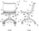
- a chair 1comprises a backrest 10, a seat body 20, a pair of left and right leg parts 30, 40, and a support frame 50 extending in a left-right direction as shown in FIGS. 1A-1E .
- a usercan stack a plurality of the identical chairs 1 in a front-rear direction for storage (see FIG. 5 ).
- the backrest 10has a shape, on the whole, to fit along the back of a seated person.
- the backrest 10is a plate-like member in an arc-like shape being convex backward in a plan view.
- the backrest 10comprises a strip-like piece 11 and a pair of backrest-side connecting pieces 13.
- the strip-like piece 11extends backward from a top end of the backrest 10.
- the pair of backrest-side connecting pieces 13extends downward from a bottom end of the backrest 10 to be connected to the support frame 50, one backrest-side connecting piece 13 from a left side and the other backrest-side connecting piece 13 from a right side of the bottom end of the backrest 10.
- the strip-like piece 11comprises two portions 11a and a portion 11b.
- the two portions 11aextend backward from the top end of the backrest 10, one portion 11a from a left side and the other portion 11a from a right side of the top end of the backrest 10.
- the portion 11bis a strip-like portion that connects the two portions 11a to each other in the left-right direction.
- the portions 11a and 11bprovide a laterally long space 11c.
- the strip-like piece 11can be used as a handle when, for example, the chair 1 is moved.
- the strip-like piece 11is not limited to the above-described configuration and may comprise only the strip-like portion as shown in FIG. 4A . In other words, a configuration may be adopted in which no laterally long space is provided in a top-end area of the backrest 10.
- the pair of backrest-side connecting pieces 13is provided to the backrest 10 in a positional relationship that allows a rear end of the seat body 20 to be held between both connecting pieces 13 from left and right. As shown in FIGS. 2A , the pair of backrest-side connecting pieces 13 fixes the seat body 20 rotatably about an axis body 15 extending in the left-right direction. This configuration enables a rotation of the seat body 20 between an in-use state ( FIG. 3A ) and a stored state ( FIG. 3B ).
- the in-use statea state in which the seat body 20 is pulled down to locate the seating surface approximately parallel to the surface on which the chair 1 is placed.
- the stored stateis a state in which the seat body 20 is flipped up to locate the seating surface approximately vertical to the surface on which the chair 1 is placed. "Being approximately parallel" and “being approximately vertical” here do not mean to be completely parallel and completely vertical, respectively.
- the backrest 10is supported above the seat body 20 by the support frame 50. This configuration provides a laterally long space 11d between the rear end of the seat body 20 and the bottom end of the backrest 10 as shown in FIG. 3C .
- the seat body 20is configured where a sheet-like member 23 to be used as a seating surface is stretched across an area enclosed in a frame body 21 that is rectangular in a plan view (see FIG. 1A , etc.).
- the frame body 21comprises a top frame body 21a and a bottom frame body 21b as shown in FIG. 2B .
- the top frame body 21a and the bottom frame body 21bare stacked in a top-bottom direction (up-down direction). Detailed description being omitted, the sheet-like member 23 is stretched across the top frame body 21a.
- the bottom frame body 21bis provided with a pair of positioning members 100 described below.
- the seat body 20comprises a tilted surface with a gradient rising from the rear end to the front end of the seat body 20 in the in-use state (see FIG. 1C ).
- the front end of the seat body 20has a suspended portion 20a suspending downward.
- the seat body 20is provided with a pair of seat-side fixing pieces 25 to fix the seat body 20 to the backrest 10 (one seat-side fixing piece 25 on a left side and the other seat-side fixing piece 25 on a right side of the rear end of the seat body 20) at positions of the seat body 20 that correspond to the pair of backrest-side connecting pieces 13 of the backrest 10. Passing the axis body 15 described above through the pair of seat-side fixing pieces 25 to fix the seat body 20 and the backrest 10 to each other permits the entire seat body 20 to rotate with respect to the backrest 10 (see FIGS. 3A and 3B ).
- the pair of positioning members 100is provided to the frame body 21 on back surfaces of a left piece and a right piece thereof extending in the front-rear direction respectively on a left side and a right side thereof, one positioning member 100 on each of the respective back surfaces of the pieces.
- the pair of positioning members 100positions the seat body 20 to be in a seatable state.
- the pair of positioning members 100protrudes from a back surface of the seat body 20, and each has a shape in which a front-rear width thereof is made narrower toward a far side from the seat body 20 in a side view (a trapezoidal shape according to the present embodiment).
- An amount of protrusion of the pair of positioning members 100 from the seat body 20is determined so that a lowest part of the sheet-like member 23 at the time the sheet-like member 23 is deformed when a user sits down is brought into a positional relationship in which the pair of positioning members 100 contacts the support frame 50 while the lowest part of the sheet-like member 23 is located above a top of the support frame 50.
- the pair of positioning members 100protrudes from the back surface of the seat body 20 in such a manner as to be inclined inward in the left-right direction, thereby contacting the support frame 50 at positions within an outer left side and an outer right side of the seat body 20 (see FIG. 1B ).
- the positioning member 100comprises a set of protruding pieces 101 and a connecting piece 103.
- the set of protruding pieces 101is configured as described below. Specifically, as shown in FIG. 2A , in a case where a front-rear position in the seat body 20 that corresponds to ischial tuberosities of a seated person (i.e., a position along the front-rear direction in which ischial tuberosities of a seated person are assumed to be located) is assumed as a reference position A, the set of protruding pieces 101 is configured to protrude from a back surface of the frame body 21, one protruding piece 101 from a front end and the other protruding piece 101 from a rear end of a given region B that includes the reference position A and extends in the front-rear direction on the back surface thereof.
- the connecting piece 103connects the set of protruding pieces 101 to each other at their respective ends. Positioning of the seat body 20 is achieved by contact of the connecting piece 103 with the support frame 50.
- the positioning member 100is not limited to the configuration including the set of protruding pieces 101 and the connecting piece 103, and may be, for example, a protrusion that protrudes from the entirety of the given region B on the back surface of the frame body 21, as shown in FIG. 4B .
- the pair of positioning members 100is connected to each other by reinforcing frames 105 extending in the left-right direction, as shown in FIG. 3B .
- the reinforcing frames 105are shown to be configured to connect the pair of positioning members 100 to each other only at respective front ends and rear ends of both positioning members 100, but are not limited to this configuration.
- a plate-like membermay be used as a reinforcing frame 105, as shown in FIG. 4C .
- a configurationmay be adopted in which the reinforcing frame 105 connects the pair of positioning members 100 to each other along the entire front-rear width of both positioning members 100.
- no reinforcing frame 105may be provided as shown in FIG. 6B .
- the positioning member 100has a height that is determined so that a lowest part of the sheet-like member 23 deformed under the load as in the static strength test or the shock resistance test defined by the Japanese Industrial Standards (S1203) concerning the test methods for strength and durability of chairs does at least not contact an upper surface of the support frame 50 (the height being the amount of protrusion from the back surface of the frame body 21, which is specifically 50 mm as a height (amount of protrusion) according to the size of the load and the elasticity of the sheet-like member 23).
- S1203Japanese Industrial Standards
- the configuration in which the lowest part of the seat body 20 (the lowest part of the sheet-like member 23) under the above-described load does not contact the upper surface of the support frame 50does not cause the lowest part of the sheet-like member 23 to contact the upper surface of the support frame 50 when the sheet-like member 23 is deformed by a user who weighs as much as or less than the load.
- the leg parts 30, 40respectively comprise front legs 31, 41, rear legs 33, 43, and casters 35, 45.
- the front legs 31, 41are provided to extend obliquely forward from the bottoms of end portions of the support frame 50.
- the rear legs 33, 43are provided to extend obliquely backward from the bottoms of end portions of the support frame 50, the end portions being located outside those of the front legs 31, 41.
- the casters 35, 45are provided to the bottom ends of the legs.
- a leg bodyis configured where the support frame 50 is supported by the leg parts 30, 40.
- a configurationmay be adopted in which the chair 1 does not comprise the casters 35, 45.
- the leg parts 30, 40are configured so that a distance between the rear legs 33, 43 is larger than a distance between the front legs 31, 41. This configuration enables the chairs 1 of an identical shape to be stacked in the front-rear direction.
- the support frame 50comprises a plate-like main frame 51 extending in the left-right direction and a pair of support-side connecting pieces 53.
- the main frame 51connects the leg parts 30, 40 to each other in the left-right direction.
- the pair of support-side connecting pieces 53extends upward from the main frame 51 to be connected to the backrest 10, one support-side connecting piece 53 from a top of a left end and the other support-side connecting piece 53 from a top of a right end of the main frame 51. As shown in FIG.
- an upper surface of the main frame 51comprises a contact surface with the positioning member 100, and the main frame 51 (support frame 50) is provided so that part thereof contacts or intersects a line extended along a line corresponding to a front end of the positioning member 100 in a side view.
- a front end of the main frame 51is configured to include a curved surface sloped downward (in a semi-circular shape according to the present embodiment in a side view).
- the front end of the main frame 51 and a projection 107 provided to the far side of the positioning member 100are configured to fit to each other.
- the chair 1 configured as abovecan be brought into the stored state by flipping up the seat body 20 so that the chairs 1 can be stacked in the front-rear direction, as shown in FIG. 5 .
- the chair 1 configured as suchcan save the storage space when it is not in use (when it is stored).
- the above-described embodimenthas been exemplified by the configuration in which the plate-like member extending in the left-right direction is employed as a main frame 51 of the support frame 50.
- the main frame 51is not limited to this configuration, and a cylindrical member extending in the left-right direction, for example, may be employed as shown in FIG. 6B .
- This configurationmay be such as described below, in view of the fact that the positioning member 100 is easily elastically deformed along an outer circumferential curved surface of the main frame 51 (support frame 50).
- the main frame 51 (support frame 50)may be configured and arranged so as not to contact or intersect the line extended along the line corresponding to the front end of the positioning member 100 in a side view.
- the contact area between the support frame 50 and the positioning member 100may be configured as described below, from a viewpoint of positioning the seat body 20 and ensuring the strength of the chair 1.
- the support frame 50may have an inward regulating piece 55 and/or an outward regulating piece 57 in an area thereof that is in or adjacent to the contact area with the positioning member 100.
- the inward regulating piece 55regulates an inward displacement of the positioning member 100 in the left-right direction
- the outward regulating piece 57regulates an outward displacement of the positioning member 100 in the left-right direction.
- FIG. 7shows an example where the support frame 50 is provided with a protrusion in which an outer side thereof in the left-right direction functions as the inward regulating piece 55 and an inner side thereof in the left-right direction functions as the outward regulating piece 57.
- the positioning member 100is provided with a positioning hole 109 to receive the protrusion that functions as the inward regulating piece 55 and the outward regulating piece 57.
- the inward regulating piece 55 and the outward regulating piece 57may be configured as separate members or may be configured to be arranged, respectively, inside and outside the positioning member 100 in the left-right direction.
- the positioning member 100has a trapezoidal shape in which the front-rear width thereof is made linearly narrower toward the far side from the seat body 20 in a side view.
- the positioning member 100may have any other shape in which the front-rear width thereof is made narrower toward the far side from the seat body 20.
- the positioning member 100may be configured to further comprise an extended area 120 extending forward in a side view and to have a shape in which a front-rear width thereof including the extended area 120 is made narrower toward the far side from the seat body 20.
- the extended area 120can be extended to a given position located between a front end surface of a main portion of the positioning member 100 and an area of the seat body 20 in which the seat body 20 starts to suspend downward.
- the above-described embodimenthas been exemplified by the configuration in which the leg body comprises the set of left and right leg parts 30, 40 and the support frame 50 connecting the leg parts 30, 40 to each other in the left-right direction, in which the support frame 50 is supported by the leg parts 30, 40.
- the leg bodyis only required to have a configuration in which the support frame 50 extending in the left-right direction is supported by the leg parts 30, 40 and is not limited to the configuration in the above-described embodiment.
- the leg bodycomprises a support frame 50, an axis body 210 extending downward from below the support frame 50, and leg parts 30, 40 attached rotatably with respect to the axis body 210.
- a cylindrical body 220that can rotate about the axis body 210 and the legs 31, 41, 33, 43 of the leg parts 30, 40 that extend from an outer circumferential surface of the cylindrical body 220 in directions differing from each other can be provided.
- a distance between the rear legs 33, 43is generally larger than a distance between the front legs 31, 41.
- the rear legs 33, 43are provided to a higher position than a position of the front legs 31, 41.
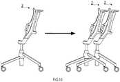
- the chair 1 having such a leg bodycan be brought into the stored state by flipping up the seat body 20 so that the chairs 1 can be stacked in the front-rear direction, as shown in FIG. 10 .
- This configurationenables the storage space to be saved when the chair 1 is not in use (when it is stored).
- the chair 1configured as such, even when the sheet-like member 23 is deformed when the user sits on the seat body 20, the lowest part of the sheet-like member 23 does not contact the support frame 50 in spite of the structure being employed in which the load is received by the support frame 50 arranged directly under the seat body 20, and thus the deformation of the sheet-like member 23 caused when the user sits down is not hindered.
- the front-rear position in the seat body 20 that corresponds to the ischial tuberosities of a seated personi.e., the position along the front-rear direction where the ischial tuberosities of a seated person are assumed to be located can be the position of the center of gravity of the seated person in the front-rear direction, it is effective that the load is received in the region B extending forward and backward from this position being the reference position A on the back surface of the frame body 21 of the seat body 20 so as to ensure the strength of the chair 1 when the user sits down.
- the above-described configurationenables the load to be received by pair of the positioning members 100 in the region B that can include the position of the center of gravity of the seated person in the seat body 20, thus advantageously ensuring the strength of the chair 1 when the user sits down.
- the positioning member 100comprises the set of protruding pieces 101 and the connecting piece 103
- elastic deformationcan easily occur because of a frame-like structure formed by the set of protruding pieces 101 and the connecting piece 103.
- a design in which the frame-like structure is elastically deformed only by a load that exceeds the load applied while the user is seatedpermits the chair to have the function of absorbing a large load caused when the user sits down.
- the front-rear width of the positioning member 100is made narrower toward the far side from the seat body 20
- the front-rear width of the area of the support frame 50 contacting the positioning member 100can also be reduced according to the front-rear width of the positioning member 100, and thus, the compactness of the chair 1 can further be improved when it is not in use (when it is stored).
- connecting the pair of positioning members 100 to each other by the reinforcing frame 105can further improve the strength of the chair 1 when the user sits down.
- the contact of the pair of positioning members 100 with the support frame 50 at positions within the outer left side and the outer right side of the seat body 20secures certain distances from the outer sides to the contact areas, which can result in reduced occurrence of an object being caught in the contact areas.
- the configuration in which the support frame 50 is provided with the inner regulating piece 55 and/or the outer regulating piece 57enables the user to securely and easily position the seat body 20 to be in a seatable state. This is because the inward regulating piece 55 and/or the outward regulating piece 57 of the support frame 50 are provided in an area that is in or adjacent to the contact area of the support frame 50 with the positioning member 100 so that the positional relationship between the support frame 50 and the positioning member 100 is clarified.
- the inner regulating piece 55regulates this displacement so that the strength of the chair 1 at the time the user sits down is further increased.
- the outer regulating piece 57regulates this displacement so that unintended deformation caused by such a load can be reduced.
- the positioning member 100is configured to comprise the extended area 120 and to have a shape in which the front-rear width thereof including the extended area 120 is made narrower toward the far side from the seat body 20, the front ends of both positioning members 100, each front end including the extended area 120, support and reinforce the left side and the right side of the seat body 20 from the back.
- the strength of the seat body 20can be improved.
- the seat body 20bends gradually more toward its front end, the deformation of the seat body 20 caused by contact of the legs (especially, the back of the thighs) of the seated person is less likely to be hindered. This results in increased seating comfort.
Landscapes
- Chairs Characterized By Structure (AREA)
- Chair Legs, Seat Parts, And Backrests (AREA)
Description
- The present invention relates to a chair that comprises a leg body and a seat body.
- A chair is conventionally known, as a chair to be used in a hall, etc., that can be stacked in a front-rear direction for storage while its seat body is flipped up in order to reduce storage space for the chair when it is not in use.
- It is common for this type of chair to position the seat body by means of a frame extending in a left-right direction in an upper part of the leg body so as not only to permit more compact storage of the chair in a stored state but also to ensure a sufficient strength of the chair (see, for example,
JP2005-279032 JP2005-218534 - Further, from the viewpoint of seating comfort, the seat body comprises a sheet-like member stretched across the frame body to thereby enhance seating comfort of the chair.
GB 928 202 JP2008-113937 JP10-2013-0079727 WO 2012/060462 A1 describes a chair which can be nested both fore and aft, having a support configuration with which it is possible to nest the chair, wherein the chair comprises a horizontal bar with which the bottom face of the seat makes contact and which supports said seat in horizontal state. A front and rear pair of legs extend at an incline, whereby the front pair of legs is positioned either more outward or more inward than the rear pair of legs.US 2006/0055220 A1 discloses a chair comprising a protruding positioning member provided on the back surface of a frame body. The seat body is not rotatable.- The techniques described in the above patent documents employ a structure in which a frame provided directly under the seat body receives the load to maintain compactness of the chair. In this case, downward deformation of the sheet-like member caused when a user sits down on the seat body can lead the sheet-like member to contact the frame. This can result in reduced seating comfort.
- It is preferable, in an aspect of the present invention, to improve the seating comfort of the chair without reducing the compactness thereof in a stored state.
- A chair in one aspect of the present invention is provided according to
claim 1. - According to the chair configured as such, even in a case where it has a support frame provided directly under the seat body to ensure the compactness, the lowest part of the sheet-like member at the time the sheet-like member is deformed when the user sits down on the seat body does not contact the support frame. Thus, the deformation of the sheet-like member is not hindered by the support frame when the user sits down. In other words, the sheet-like member can be deformed to its maximum extent according to the load (the weight of the user who sits down). Hence, no deterioration in the seating comfort of the chair occurs; accordingly, the comfort of the user can be ensured. In this way, the seating comfort of the chair can be enhanced while the compactness thereof in a stored state is maintained.
- Now, a position that corresponds to ischial tuberosities of a seated person, specifically a position where ischial tuberosities of a seated person are assumed to be located can be the position of the center of gravity of the seated person. Thus, it is effective that the load is received in a region, on the back surface of the frame body, extending forward and backward from a reference position that is the position corresponding to the ischial tuberosities of the seated person so as to ensure the strength of the chair when the user sits down.
- According to a chair in another aspect of the present invention, the positioning member may comprise a set of protruding pieces, one protruding piece protruding from a front end and the other protruding piece protruding from a rear end of a given region including the reference position on the back surface of the frame body, and a connecting piece that connects the set of protruding pieces to each other so that positioning of the seat body is achieved by contact of the connecting piece with the support frame.
- According to a chair in still another aspect of the present invention, the positioning member may be configured as a plate-like protrusion that protrudes from a given region including the reference position on the back surface of the frame body.
- Such a chair can receive the load by means of the positioning member in a region of the seat body that can include the position of the center of gravity of the seated person. This can advantageously ensure the strength of the chair when the user sits down.
- Especially, the configuration in which the positioning member comprises the set of protruding pieces and the connecting piece allows elastic deformation of the positioning member to easily occur because of this frame-like structure. For example, a design of the positioning member in which the positioning member is elastically deformed only by a load that exceeds the load applied while the user is seated permits the chair to have the function of absorbing a large load caused when the user sits down.
- According to a chair in still another aspect of the present invention, the positioning member may have a shape in which a front-rear width thereof is made narrower toward a far side from the seat body. An upper surface of the support frame may comprise a contact surface with the positioning member, and the support frame may be provided so that part thereof contacts or intersects a line extended along a line corresponding to a front end of the positioning member in a side view.
- According to the chair configured as such, since the front-rear width of the positioning member is made narrower toward the far side from the seat body, the front-rear width of the area of the support frame that contacts the positioning member can also be reduced according to the front-rear width of the positioning member, and thus, the compactness of the chair can further be improved when it is stored.
- According to a chair in still another aspect of the present invention, the positioning member may comprise an extended area extending forward in a side view and may have a shape in which a front-rear width thereof including the extended area is made narrower toward the far side from the seat body.
- According to the chair configured as such, a front end of the positioning member including the extended area can support and, at the same time, reinforce a left side and/or a right side of the seat body from the back. In such a case, the strength of the seat body can be improved. The front end of the positioning member including the extended area functions to bend the seat body gradually more toward its front end. Thus, the deformation of the seat body caused by contact of the legs (especially, the back of the thighs) of the user who sits down is less likely to be hindered to result in increase in the seating comfort of the chair.
- According to a chair in still another aspect of the present invention, the positioning member may comprise a pair of positioning members, and the chair may further comprise a reinforcing frame that connects the far side, from the seat body, of one of the pair of positioning members and the far side, from the seat body, of the other of the pair of positioning members to each other.
- According to the chair configured as such, the reinforcing frame can further improve the strength of the chair.
- According to a chair in still another aspect of the present invention, the support frame may have, on an upper surface thereof, an inward regulating piece that regulates an inward displacement of the positioning member in the left-right direction, the inward regulating piece being provided in an area that is in or adjacent to a contact area of the support frame with the positioning member.
- According to a chair in still another aspect of the present invention, the support frame may have, on an upper surface thereof, an outward regulating piece that regulates an outward displacement of the positioning member in the left-right direction, the outward regulating piece being provided in an area that is in or adjacent to a contact area of the support frame with the positioning member.
- The chair in these configurations has a regulating piece arranged in the area that is in or adjacent to the contact area with the positioning member, and thus the positional relationship between the regulating piece and the positioning member can be clarified. In such a case, the user can securely and easily position the seat body.
- According to the configuration including the inward regulating piece, even in a case where the positioning member is displaced inward in the left-right direction by the load applied when the user sits down, the inner regulating piece regulates this displacement so that the strength of the chair at the time the user sits down is further improved.
- According to the configuration including the outward regulating piece, even in a case where the positioning member is displaced outward in the left-right direction by the large load applied, for example, when the user sits down, the outer regulating piece regulates this displacement so that unintended deformation caused by such a load can be reduced.
- According to a chair in still another aspect of the present invention, the positioning member may be configured to protrude from the back surface of the seat body in such a manner as to be inclined inward in the left-right direction so that the positioning member contacts the support frame at a position within an outer left side or an outer right side of the seat body.
- According to the chair configured as such, the contact of the positioning member with the support frame at a position within the outer left side or the outer right side of the seat body secures a certain distance from the outer side to the contact area. This can result in reduced occurrence of an object being caught in the contact area.
- The present invention will now be described by way of exemplary embodiments with reference to the accompanying drawings, in which:
FIGS. 1A-1E are six views illustrating an entire configuration of a chair (a left side view is omitted);FIGS. 2A and 2B are cross-sectional views along line II-II of a front view;FIGS. 3A-3C are perspective views illustrating characteristic portions of the chair;FIGS. 4A-4C are perspective views illustrating characteristic portions of a chair in another embodiment;FIG. 5 is a view illustrating how a plurality of the chairs is brought into a nested state;FIGS. 6A-6C are perspective views illustrating characteristic portions of a chair in still another embodiment;FIG. 7 is a front view illustrating main components of characteristic portions of a chair in still another embodiment;FIG. 8 is a right side view illustrating main components of a frame body of a seat body in still another embodiment;FIGS. 9A and 9B are a front view and a right side view illustrating an entire configuration of a chair in still another embodiment; andFIG. 10 is a view illustrating how a plurality of the chairs is brought into a nested state.- A
chair 1 comprises abackrest 10, aseat body 20, a pair of left andright leg parts support frame 50 extending in a left-right direction as shown inFIGS. 1A-1E . A user can stack a plurality of theidentical chairs 1 in a front-rear direction for storage (seeFIG. 5 ). - The
backrest 10 has a shape, on the whole, to fit along the back of a seated person. Specifically, thebackrest 10 is a plate-like member in an arc-like shape being convex backward in a plan view. Thebackrest 10 comprises a strip-like piece 11 and a pair of backrest-side connecting pieces 13. The strip-like piece 11 extends backward from a top end of thebackrest 10. The pair of backrest-side connecting pieces 13 extends downward from a bottom end of thebackrest 10 to be connected to thesupport frame 50, one backrest-side connecting piece 13 from a left side and the other backrest-side connecting piece 13 from a right side of the bottom end of thebackrest 10. - The strip-
like piece 11 comprises twoportions 11a and aportion 11b. The twoportions 11a extend backward from the top end of thebackrest 10, oneportion 11a from a left side and theother portion 11a from a right side of the top end of thebackrest 10. Theportion 11b is a strip-like portion that connects the twoportions 11a to each other in the left-right direction. Theportions long space 11c. The strip-like piece 11 can be used as a handle when, for example, thechair 1 is moved. The strip-like piece 11 is not limited to the above-described configuration and may comprise only the strip-like portion as shown inFIG. 4A . In other words, a configuration may be adopted in which no laterally long space is provided in a top-end area of thebackrest 10. - The pair of backrest-
side connecting pieces 13 is provided to thebackrest 10 in a positional relationship that allows a rear end of theseat body 20 to be held between both connectingpieces 13 from left and right. As shown inFIGS. 2A , the pair of backrest-side connecting pieces 13 fixes theseat body 20 rotatably about anaxis body 15 extending in the left-right direction. This configuration enables a rotation of theseat body 20 between an in-use state (FIG. 3A ) and a stored state (FIG. 3B ). The in-use state a state in which theseat body 20 is pulled down to locate the seating surface approximately parallel to the surface on which thechair 1 is placed. The stored state is a state in which theseat body 20 is flipped up to locate the seating surface approximately vertical to the surface on which thechair 1 is placed. "Being approximately parallel" and "being approximately vertical" here do not mean to be completely parallel and completely vertical, respectively. - The
backrest 10 is supported above theseat body 20 by thesupport frame 50. This configuration provides a laterallylong space 11d between the rear end of theseat body 20 and the bottom end of thebackrest 10 as shown inFIG. 3C . - The
seat body 20 is configured where a sheet-like member 23 to be used as a seating surface is stretched across an area enclosed in aframe body 21 that is rectangular in a plan view (seeFIG. 1A , etc.). According to the present embodiment, theframe body 21 comprises a top frame body 21a and abottom frame body 21b as shown inFIG. 2B . The top frame body 21a and thebottom frame body 21b are stacked in a top-bottom direction (up-down direction). Detailed description being omitted, the sheet-like member 23 is stretched across the top frame body 21a. Thebottom frame body 21b is provided with a pair ofpositioning members 100 described below. Theseat body 20 comprises a tilted surface with a gradient rising from the rear end to the front end of theseat body 20 in the in-use state (seeFIG. 1C ). The front end of theseat body 20 has a suspendedportion 20a suspending downward. - The
seat body 20 is provided with a pair of seat-side fixing pieces 25 to fix theseat body 20 to the backrest 10 (one seat-side fixing piece 25 on a left side and the other seat-side fixing piece 25 on a right side of the rear end of the seat body 20) at positions of theseat body 20 that correspond to the pair of backrest-side connecting pieces 13 of thebackrest 10. Passing theaxis body 15 described above through the pair of seat-side fixing pieces 25 to fix theseat body 20 and thebackrest 10 to each other permits theentire seat body 20 to rotate with respect to the backrest 10 (seeFIGS. 3A and 3B ). - The pair of
positioning members 100 is provided to theframe body 21 on back surfaces of a left piece and a right piece thereof extending in the front-rear direction respectively on a left side and a right side thereof, onepositioning member 100 on each of the respective back surfaces of the pieces. The pair ofpositioning members 100 positions theseat body 20 to be in a seatable state. - The pair of
positioning members 100 protrudes from a back surface of theseat body 20, and each has a shape in which a front-rear width thereof is made narrower toward a far side from theseat body 20 in a side view (a trapezoidal shape according to the present embodiment). An amount of protrusion of the pair ofpositioning members 100 from theseat body 20 is determined so that a lowest part of the sheet-like member 23 at the time the sheet-like member 23 is deformed when a user sits down is brought into a positional relationship in which the pair ofpositioning members 100 contacts thesupport frame 50 while the lowest part of the sheet-like member 23 is located above a top of thesupport frame 50. The pair ofpositioning members 100 protrudes from the back surface of theseat body 20 in such a manner as to be inclined inward in the left-right direction, thereby contacting thesupport frame 50 at positions within an outer left side and an outer right side of the seat body 20 (seeFIG. 1B ). - The positioning
member 100 comprises a set of protrudingpieces 101 and a connectingpiece 103. The set of protrudingpieces 101 is configured as described below. Specifically, as shown inFIG. 2A , in a case where a front-rear position in theseat body 20 that corresponds to ischial tuberosities of a seated person (i.e., a position along the front-rear direction in which ischial tuberosities of a seated person are assumed to be located) is assumed as a reference position A, the set of protrudingpieces 101 is configured to protrude from a back surface of theframe body 21, one protrudingpiece 101 from a front end and the other protrudingpiece 101 from a rear end of a given region B that includes the reference position A and extends in the front-rear direction on the back surface thereof. The connectingpiece 103 connects the set of protrudingpieces 101 to each other at their respective ends. Positioning of theseat body 20 is achieved by contact of the connectingpiece 103 with thesupport frame 50. The positioningmember 100 is not limited to the configuration including the set of protrudingpieces 101 and the connectingpiece 103, and may be, for example, a protrusion that protrudes from the entirety of the given region B on the back surface of theframe body 21, as shown inFIG. 4B . - The pair of
positioning members 100 is connected to each other by reinforcingframes 105 extending in the left-right direction, as shown inFIG. 3B . The reinforcingframes 105 are shown to be configured to connect the pair ofpositioning members 100 to each other only at respective front ends and rear ends of both positioningmembers 100, but are not limited to this configuration. A plate-like member may be used as a reinforcingframe 105, as shown inFIG. 4C . Specifically, a configuration may be adopted in which the reinforcingframe 105 connects the pair ofpositioning members 100 to each other along the entire front-rear width of both positioningmembers 100. Alternatively, no reinforcingframe 105 may be provided as shown inFIG. 6B . - The positioning
member 100 has a height that is determined so that a lowest part of the sheet-like member 23 deformed under the load as in the static strength test or the shock resistance test defined by the Japanese Industrial Standards (S1203) concerning the test methods for strength and durability of chairs does at least not contact an upper surface of the support frame 50 (the height being the amount of protrusion from the back surface of theframe body 21, which is specifically 50 mm as a height (amount of protrusion) according to the size of the load and the elasticity of the sheet-like member 23). The configuration in which the lowest part of the seat body 20 (the lowest part of the sheet-like member 23) under the above-described load does not contact the upper surface of thesupport frame 50 does not cause the lowest part of the sheet-like member 23 to contact the upper surface of thesupport frame 50 when the sheet-like member 23 is deformed by a user who weighs as much as or less than the load. - The
leg parts front legs rear legs casters front legs support frame 50. Therear legs support frame 50, the end portions being located outside those of thefront legs casters support frame 50 is supported by theleg parts chair 1 does not comprise thecasters - The
leg parts rear legs front legs chairs 1 of an identical shape to be stacked in the front-rear direction. - The
support frame 50 comprises a plate-likemain frame 51 extending in the left-right direction and a pair of support-side connecting pieces 53. Themain frame 51 connects theleg parts side connecting pieces 53 extends upward from themain frame 51 to be connected to thebackrest 10, one support-side connecting piece 53 from a top of a left end and the other support-side connecting piece 53 from a top of a right end of themain frame 51. As shown inFIG. 2A , an upper surface of the main frame 51 (support frame 50) comprises a contact surface with the positioningmember 100, and the main frame 51 (support frame 50) is provided so that part thereof contacts or intersects a line extended along a line corresponding to a front end of thepositioning member 100 in a side view. - A front end of the
main frame 51 is configured to include a curved surface sloped downward (in a semi-circular shape according to the present embodiment in a side view). The front end of themain frame 51 and aprojection 107 provided to the far side of thepositioning member 100 are configured to fit to each other. - The
chair 1 configured as above can be brought into the stored state by flipping up theseat body 20 so that thechairs 1 can be stacked in the front-rear direction, as shown inFIG. 5 . Thechair 1 configured as such can save the storage space when it is not in use (when it is stored). - Although the embodiment of the present invention has been described above, the present invention is not at all limited to the above-described embodiment and can be practiced in various forms without departing from the technical scope of the present invention.
- For example, the above-described embodiment has been exemplified by the configuration in which the plate-like member extending in the left-right direction is employed as a
main frame 51 of thesupport frame 50. However, themain frame 51 is not limited to this configuration, and a cylindrical member extending in the left-right direction, for example, may be employed as shown inFIG. 6B . - This configuration may be such as described below, in view of the fact that the
positioning member 100 is easily elastically deformed along an outer circumferential curved surface of the main frame 51 (support frame 50). Specifically, the main frame 51 (support frame 50) may be configured and arranged so as not to contact or intersect the line extended along the line corresponding to the front end of thepositioning member 100 in a side view. - According to the above-described embodiment, the contact area between the
support frame 50 and thepositioning member 100 may be configured as described below, from a viewpoint of positioning theseat body 20 and ensuring the strength of thechair 1. Specifically, as shown inFIG. 7 , thesupport frame 50 may have aninward regulating piece 55 and/or anoutward regulating piece 57 in an area thereof that is in or adjacent to the contact area with the positioningmember 100. Theinward regulating piece 55 regulates an inward displacement of thepositioning member 100 in the left-right direction, and theoutward regulating piece 57 regulates an outward displacement of thepositioning member 100 in the left-right direction. FIG. 7 shows an example where thesupport frame 50 is provided with a protrusion in which an outer side thereof in the left-right direction functions as theinward regulating piece 55 and an inner side thereof in the left-right direction functions as theoutward regulating piece 57. According to this example, the positioningmember 100 is provided with apositioning hole 109 to receive the protrusion that functions as theinward regulating piece 55 and theoutward regulating piece 57. Theinward regulating piece 55 and theoutward regulating piece 57 may be configured as separate members or may be configured to be arranged, respectively, inside and outside the positioningmember 100 in the left-right direction.- The above-described embodiment has been exemplified by the configuration in which the
positioning member 100 has a trapezoidal shape in which the front-rear width thereof is made linearly narrower toward the far side from theseat body 20 in a side view. However, the positioningmember 100 may have any other shape in which the front-rear width thereof is made narrower toward the far side from theseat body 20. Specifically, as shown inFIG. 8 , the positioningmember 100 may be configured to further comprise anextended area 120 extending forward in a side view and to have a shape in which a front-rear width thereof including the extendedarea 120 is made narrower toward the far side from theseat body 20. Theextended area 120 can be extended to a given position located between a front end surface of a main portion of thepositioning member 100 and an area of theseat body 20 in which theseat body 20 starts to suspend downward. - The above-described embodiment has been exemplified by the configuration in which the leg body comprises the set of left and
right leg parts support frame 50 connecting theleg parts support frame 50 is supported by theleg parts support frame 50 extending in the left-right direction is supported by theleg parts - As shown in
FIGS. 9A and 9B , for example, a configuration is possible in which the leg body comprises asupport frame 50, anaxis body 210 extending downward from below thesupport frame 50, andleg parts axis body 210. According to this configuration, acylindrical body 220 that can rotate about theaxis body 210 and thelegs leg parts cylindrical body 220 in directions differing from each other can be provided. According to this configuration, a distance between therear legs front legs rear legs front legs - The
chair 1 having such a leg body can be brought into the stored state by flipping up theseat body 20 so that thechairs 1 can be stacked in the front-rear direction, as shown inFIG. 10 . This configuration enables the storage space to be saved when thechair 1 is not in use (when it is stored). - According to the
chair 1 configured as such, even when the sheet-like member 23 is deformed when the user sits on theseat body 20, the lowest part of the sheet-like member 23 does not contact thesupport frame 50 in spite of the structure being employed in which the load is received by thesupport frame 50 arranged directly under theseat body 20, and thus the deformation of the sheet-like member 23 caused when the user sits down is not hindered. This leads to advantageous improvement in the seating comfort of thechair 1 while ensuring the compactness thereof when it is not in use (when it is stored). - According to the
chair 1 configured as described above, since the front-rear position in theseat body 20 that corresponds to the ischial tuberosities of a seated person, i.e., the position along the front-rear direction where the ischial tuberosities of a seated person are assumed to be located can be the position of the center of gravity of the seated person in the front-rear direction, it is effective that the load is received in the region B extending forward and backward from this position being the reference position A on the back surface of theframe body 21 of theseat body 20 so as to ensure the strength of thechair 1 when the user sits down. In this regard, the above-described configuration enables the load to be received by pair of thepositioning members 100 in the region B that can include the position of the center of gravity of the seated person in theseat body 20, thus advantageously ensuring the strength of thechair 1 when the user sits down. - In the case where the
positioning member 100 comprises the set of protrudingpieces 101 and the connectingpiece 103, elastic deformation can easily occur because of a frame-like structure formed by the set of protrudingpieces 101 and the connectingpiece 103. In such a case, a design in which the frame-like structure is elastically deformed only by a load that exceeds the load applied while the user is seated permits the chair to have the function of absorbing a large load caused when the user sits down. - According to the above-described configuration, since the front-rear width of the
positioning member 100 is made narrower toward the far side from theseat body 20, the front-rear width of the area of thesupport frame 50 contacting thepositioning member 100 can also be reduced according to the front-rear width of thepositioning member 100, and thus, the compactness of thechair 1 can further be improved when it is not in use (when it is stored). - Further, according to the above-described configuration, connecting the pair of
positioning members 100 to each other by the reinforcingframe 105 can further improve the strength of thechair 1 when the user sits down. - According to the above-described configuration, the contact of the pair of
positioning members 100 with thesupport frame 50 at positions within the outer left side and the outer right side of theseat body 20 secures certain distances from the outer sides to the contact areas, which can result in reduced occurrence of an object being caught in the contact areas. - The configuration in which the
support frame 50 is provided with theinner regulating piece 55 and/or theouter regulating piece 57 enables the user to securely and easily position theseat body 20 to be in a seatable state. This is because theinward regulating piece 55 and/or theoutward regulating piece 57 of thesupport frame 50 are provided in an area that is in or adjacent to the contact area of thesupport frame 50 with the positioningmember 100 so that the positional relationship between thesupport frame 50 and thepositioning member 100 is clarified. - According to the configuration including the
inward regulating piece 55, even in a case where thepositioning member 100 is displaced inward in the left-right direction by the load applied when the user sits down, theinner regulating piece 55 regulates this displacement so that the strength of thechair 1 at the time the user sits down is further increased. - According to the configuration including the
outward regulating piece 57, even in a case where thepositioning member 100 is displaced outward in the left-right direction by the load applied when the user sits down, theouter regulating piece 57 regulates this displacement so that unintended deformation caused by such a load can be reduced. - According to the configuration in which the
positioning member 100 is configured to comprise theextended area 120 and to have a shape in which the front-rear width thereof including the extendedarea 120 is made narrower toward the far side from theseat body 20, the front ends of both positioningmembers 100, each front end including the extendedarea 120, support and reinforce the left side and the right side of theseat body 20 from the back. In such a case, the strength of theseat body 20 can be improved. In addition, since theseat body 20 bends gradually more toward its front end, the deformation of theseat body 20 caused by contact of the legs (especially, the back of the thighs) of the seated person is less likely to be hindered. This results in increased seating comfort.
Claims (9)
- A chair (1) comprising a leg body and a seat body (20),
wherein the leg body comprises a support frame (50) that supports the seat body (20),
wherein the seat body (20) on which a user sits down comprises a frame body (21) having a frame-like shape and an elastically deformable sheet-like member (23) that deforms under the load of the seated user stretched across the frame body (21),
wherein the frame body (21) has a positioning member (100) provided on a back surface thereof that protrudes from the back surface to contact the support frame (50), thereby positioning the seat body (20) to be in a seatable state, and
wherein an amount of protrusion of the positioning member (100) is defined so as to maintain a state in which a lowest part of the sheet-like member (23) at the time the sheet-like member (23) is deformed when a user sits down on the seat body (20) is above a top of the support frame (50),
characterized in that the seat body (20) is configured to be rotatable about an axis extending in a left-right direction on a rear side of the frame body (21). - The chair (1) according to claim 1,
wherein, in a case where a position in the seat body (20) that corresponds to ischial tuberosities of a seated person is defined as a reference position, the positioning member (100) comprises a set of protruding pieces (101), one protruding piece (101) protruding from a front end and the other protruding piece (101) protruding from a rear end of a given region including the reference position on the back surface of the frame body (21); and a connecting piece (103) that connects the set of protruding pieces (101) to each other, and
wherein positioning of the seat body (20) is achieved by contact of the connecting piece (103) with the support frame (50). - The chair (1) according to claim 1,
wherein, in a case where a position in the seat body (20) that corresponds to ischial tuberosities of a seated person is defined as a reference position, the positioning member (100) is shaped as a plate-like protrusion that protrudes from a given region including the reference position on the back surface of the frame body (21). - The chair (1) according to any one of claims 1 to 3,
wherein the positioning member (100) has a shape in which a front-rear width thereof is made narrower toward a far side from the seat body (20), and
wherein an upper surface of the support frame (50) comprises a contact surface with the positioning member (100), and the support frame (50) is provided so that part thereof contacts or intersects a line extended along a line corresponding to a front end of the positioning member (100) in a side view. - The chair (1) according to any one of claims 1 to 4,
wherein the positioning member (100) comprises an extended area extending forward in a side view and has a shape in which a front-rear width thereof including the extended area is made narrower toward a far side from the seat body (20). - The chair (1) according to any one of claims 1 to 5,
wherein the positioning member (100) comprises a pair of positioning member (100)s, and wherein the chair (1) further comprises a reinforcing frame that connects a far side, from the seat body (20), of one of the pair of positioning member (100)s and a far side, from the seat body (20), of the other of the pair of positioning member (100)s to each other. - The chair (1) according to any one of claims 1 to 6,
wherein the support frame (50) has, on an upper surface thereof, an inward regulating piece (55) that regulates an inward displacement of the positioning member (100) in a left-right direction, the inward regulating piece being provided in an area that is in or adjacent to a contact area of the support frame (50) with the positioning member (100). - The chair (1) according to any one of claims 1 to 7,
wherein the support frame (50) has, on an upper surface thereof, an outward regulating piece (57) that regulates an outward displacement of the positioning member (100) in a left-right direction, the outward regulating piece being provided in an area that is in or adjacent to a contact area of the support frame (50) with the positioning member (100). - The chair (1) according to any one of claims 1 to 8,
wherein the positioning member (100) protrudes from a back surface of the seat body (20) in such a manner as to be inclined inward in a left-right direction, thereby contacting the support frame (50) at a position within an outer left side or an outer right side of the seat body (20).
Priority Applications (1)
| Application Number | Priority Date | Filing Date | Title |
|---|---|---|---|
| EP19151489.2AEP3516992A1 (en) | 2014-04-03 | 2015-04-01 | Chair |
Applications Claiming Priority (2)
| Application Number | Priority Date | Filing Date | Title |
|---|---|---|---|
| JP2014076803 | 2014-04-03 | ||
| JP2014234674AJP6549371B2 (en) | 2014-04-03 | 2014-11-19 | chair |
Related Child Applications (1)
| Application Number | Title | Priority Date | Filing Date |
|---|---|---|---|
| EP19151489.2ADivisionEP3516992A1 (en) | 2014-04-03 | 2015-04-01 | Chair |
Publications (3)
| Publication Number | Publication Date |
|---|---|
| EP2926691A2 EP2926691A2 (en) | 2015-10-07 |
| EP2926691A3 EP2926691A3 (en) | 2015-10-28 |
| EP2926691B1true EP2926691B1 (en) | 2019-01-16 |
Family
ID=52987910
Family Applications (2)
| Application Number | Title | Priority Date | Filing Date |
|---|---|---|---|
| EP19151489.2AWithdrawnEP3516992A1 (en) | 2014-04-03 | 2015-04-01 | Chair |
| EP15162290.9AActiveEP2926691B1 (en) | 2014-04-03 | 2015-04-01 | Chair |
Family Applications Before (1)
| Application Number | Title | Priority Date | Filing Date |
|---|---|---|---|
| EP19151489.2AWithdrawnEP3516992A1 (en) | 2014-04-03 | 2015-04-01 | Chair |
Country Status (6)
| Country | Link |
|---|---|
| US (2) | US9872567B2 (en) |
| EP (2) | EP3516992A1 (en) |
| JP (1) | JP6549371B2 (en) |
| CN (2) | CN104970604A (en) |
| AU (1) | AU2015201693B2 (en) |
| HK (1) | HK1212178A1 (en) |
Families Citing this family (14)
| Publication number | Priority date | Publication date | Assignee | Title |
|---|---|---|---|---|
| JP6549371B2 (en) | 2014-04-03 | 2019-07-24 | 愛知株式会社 | chair |
| US10517400B2 (en)* | 2015-05-13 | 2019-12-31 | Series International, Llc | Stackable chair |
| JP1578205S (en)* | 2016-09-30 | 2017-06-05 | ||
| JP1578204S (en)* | 2016-09-30 | 2017-06-05 | ||
| JP1578199S (en)* | 2016-09-30 | 2017-06-05 | ||
| JP1620619S (en) | 2017-08-18 | 2018-12-17 | ||
| JP1605725S (en)* | 2017-08-10 | 2018-06-04 | ||
| JP1619486S (en)* | 2018-03-01 | 2018-12-03 | ||
| KR102057897B1 (en)* | 2019-07-19 | 2019-12-20 | 주식회사 듀오백 | Assembly type chair |
| JP7330857B2 (en)* | 2019-10-28 | 2023-08-22 | 株式会社オカムラ | Chair |
| JP7395316B2 (en)* | 2019-10-28 | 2023-12-11 | 株式会社オカムラ | Chair |
| US11166554B1 (en)* | 2020-05-29 | 2021-11-09 | Office Master Inc. | Nesting chair with flip seat and movement |
| JP7728721B2 (en)* | 2022-03-14 | 2025-08-25 | 株式会社オカムラ | chair |
| US12408756B1 (en) | 2022-05-27 | 2025-09-09 | Series International, Llc | Stacking chair with removable back |
Citations (1)
| Publication number | Priority date | Publication date | Assignee | Title |
|---|---|---|---|---|
| US20060055220A1 (en)* | 2002-09-12 | 2006-03-16 | Heidmann Kurt R | Seating unit with novel flexible supports |
Family Cites Families (30)
| Publication number | Priority date | Publication date | Assignee | Title |
|---|---|---|---|---|
| US1993530A (en)* | 1931-06-13 | 1935-03-05 | Samuel E Schaffer | Theater seat |
| US2838094A (en)* | 1957-03-22 | 1958-06-10 | William J Janning | Collapsible stool |
| FI33425A (en) | 1960-07-30 | 1963-08-10 | Horizontally stackable chairs | |
| JPS5636357Y2 (en)* | 1977-03-07 | 1981-08-27 | ||
| US5393126A (en)* | 1993-06-21 | 1995-02-28 | Art Design International Inc. | Tubular frame seating structure with tension sleeve |
| CN2498926Y (en)* | 2001-06-12 | 2002-07-10 | 北京舒适科技有限公司 | Net suspension elastic cushion |
| CN2540841Y (en)* | 2002-04-18 | 2003-03-26 | 洪少彬 | Telescopic folding chair |
| US6755468B1 (en)* | 2003-05-09 | 2004-06-29 | Oasyschair Co., Ltd. | Folding chair |
| US7108330B2 (en)* | 2003-07-23 | 2006-09-19 | Greenwich Industries, L.P. | Portable chair |
| JP4341831B2 (en) | 2004-02-04 | 2009-10-14 | 株式会社岡村製作所 | Chair |
| JP2005279032A (en) | 2004-03-30 | 2005-10-13 | Itoki Corp | Folding chair |
| DK176101B1 (en)* | 2004-11-12 | 2006-06-12 | Inter Ikea Sys Bv | Chair |
| CN2776460Y (en)* | 2005-01-14 | 2006-05-03 | 胜泰工业股份有限公司 | small trampoline structure |
| US7152929B2 (en)* | 2005-04-20 | 2006-12-26 | Comfordy Co., Ltd. | Structure of a double-mesh seat of a chair |
| JP4594849B2 (en)* | 2005-11-14 | 2010-12-08 | 株式会社岡村製作所 | Chair |
| US20070222266A1 (en)* | 2006-03-21 | 2007-09-27 | Ditto Sales, Inc. | Nestable and stackable chair |
| US7837265B2 (en)* | 2006-03-24 | 2010-11-23 | Hni Corporation | Reclining chair with enhanced adjustability |
| JP5004152B2 (en)* | 2006-03-28 | 2012-08-22 | コクヨ株式会社 | Chair |
| US20080106136A1 (en)* | 2006-04-28 | 2008-05-08 | Heidmann Kurt R | Seat front edge construction |
| JP5205625B2 (en)* | 2006-11-07 | 2013-06-05 | コクヨ株式会社 | Chair |
| US7731295B2 (en)* | 2006-11-29 | 2010-06-08 | Peter Lin | Chair having adjustable weight proportion accepting elements |
| US7708349B2 (en)* | 2007-05-04 | 2010-05-04 | Kate Chen | Knock down chair |
| CN201051989Y (en)* | 2007-06-26 | 2008-04-30 | 李百涌 | Folding chair |
| CA2751344C (en)* | 2009-02-02 | 2014-09-09 | Hni Technologies Inc. | Stacking and nesting chair |
| JP2011136101A (en)* | 2009-12-29 | 2011-07-14 | Itoki Corp | Stacking chair |
| US8540315B2 (en)* | 2010-01-21 | 2013-09-24 | Pro-Cord S.P.A. | Nestable chair with seat rotation and stop arrangement |
| JP5593524B2 (en)* | 2010-05-25 | 2014-09-24 | コクヨ株式会社 | Chair |
| WO2012060462A1 (en)* | 2010-11-05 | 2012-05-10 | 株式会社岡村製作所 | Chair |
| KR20130079727A (en) | 2012-01-03 | 2013-07-11 | 부호체어원(주) | Chair embodied with locking apparatus of seat folding |
| JP6549371B2 (en) | 2014-04-03 | 2019-07-24 | 愛知株式会社 | chair |
- 2014
- 2014-11-19JPJP2014234674Apatent/JP6549371B2/enactiveActive
- 2015
- 2015-04-01EPEP19151489.2Apatent/EP3516992A1/ennot_activeWithdrawn
- 2015-04-01USUS14/676,382patent/US9872567B2/enactiveActive
- 2015-04-01EPEP15162290.9Apatent/EP2926691B1/enactiveActive
- 2015-04-02CNCN201510154926.0Apatent/CN104970604A/enactivePending
- 2015-04-02CNCN202010046638.4Apatent/CN111387742A/enactivePending
- 2015-04-02AUAU2015201693Apatent/AU2015201693B2/enactiveActive
- 2016
- 2016-01-11HKHK16100232.0Apatent/HK1212178A1/enunknown
- 2017
- 2017-12-15USUS15/843,784patent/US10258161B2/enactiveActive
Patent Citations (1)
| Publication number | Priority date | Publication date | Assignee | Title |
|---|---|---|---|---|
| US20060055220A1 (en)* | 2002-09-12 | 2006-03-16 | Heidmann Kurt R | Seating unit with novel flexible supports |
Also Published As
| Publication number | Publication date |
|---|---|
| CN104970604A (en) | 2015-10-14 |
| JP6549371B2 (en) | 2019-07-24 |
| US9872567B2 (en) | 2018-01-23 |
| US20180103762A1 (en) | 2018-04-19 |
| US10258161B2 (en) | 2019-04-16 |
| EP2926691A2 (en) | 2015-10-07 |
| EP3516992A1 (en) | 2019-07-31 |
| JP2015198904A (en) | 2015-11-12 |
| EP2926691A3 (en) | 2015-10-28 |
| CN111387742A (en) | 2020-07-10 |
| HK1212178A1 (en) | 2016-06-10 |
| US20150282622A1 (en) | 2015-10-08 |
| AU2015201693B2 (en) | 2019-11-21 |
| AU2015201693A1 (en) | 2015-10-22 |
Similar Documents
| Publication | Publication Date | Title |
|---|---|---|
| EP2926691B1 (en) | Chair | |
| US9550440B2 (en) | Conveyance seat | |
| JP2010505507A5 (en) | ||
| JP7482941B2 (en) | Posture support device | |
| EP2862746B1 (en) | Vehicle seat | |
| JP7240024B2 (en) | chair | |
| JP6687996B2 (en) | Chair and support frame | |
| JP7330857B2 (en) | Chair | |
| JP6832906B2 (en) | chair | |
| JP6188541B2 (en) | Chair | |
| JP3240391U (en) | chairs | |
| HK40030541A (en) | Chair with improved comfortability | |
| JP6671945B2 (en) | Chair | |
| JP6379377B2 (en) | Chair | |
| JP7395316B2 (en) | Chair | |
| JP2021072953A (en) | chair | |
| JP6485731B2 (en) | Vehicle suspension seat | |
| JP2021058501A (en) | Backrest and chair | |
| JP2021194955A (en) | Seat back structure of vehicular seat | |
| JP2020124293A (en) | Chairs | |
| JP2018075079A (en) | Load support member for chair, and chair |
Legal Events
| Date | Code | Title | Description |
|---|---|---|---|
| PUAL | Search report despatched | Free format text:ORIGINAL CODE: 0009013 | |
| PUAI | Public reference made under article 153(3) epc to a published international application that has entered the european phase | Free format text:ORIGINAL CODE: 0009012 | |
| AK | Designated contracting states | Kind code of ref document:A2 Designated state(s):AL AT BE BG CH CY CZ DE DK EE ES FI FR GB GR HR HU IE IS IT LI LT LU LV MC MK MT NL NO PL PT RO RS SE SI SK SM TR | |
| AX | Request for extension of the european patent | Extension state:BA ME | |
| AK | Designated contracting states | Kind code of ref document:A3 Designated state(s):AL AT BE BG CH CY CZ DE DK EE ES FI FR GB GR HR HU IE IS IT LI LT LU LV MC MK MT NL NO PL PT RO RS SE SI SK SM TR | |
| AX | Request for extension of the european patent | Extension state:BA ME | |
| RIC1 | Information provided on ipc code assigned before grant | Ipc:A47C 4/04 20060101ALI20150923BHEP Ipc:A47C 7/56 20060101ALI20150923BHEP Ipc:A47C 3/04 20060101AFI20150923BHEP | |
| 17P | Request for examination filed | Effective date:20160427 | |
| RBV | Designated contracting states (corrected) | Designated state(s):AL AT BE BG CH CY CZ DE DK EE ES FI FR GB GR HR HU IE IS IT LI LT LU LV MC MK MT NL NO PL PT RO RS SE SI SK SM TR | |
| R17P | Request for examination filed (corrected) | Effective date:20160427 | |
| 17Q | First examination report despatched | Effective date:20160726 | |
| STAA | Information on the status of an ep patent application or granted ep patent | Free format text:STATUS: EXAMINATION IS IN PROGRESS | |
| GRAP | Despatch of communication of intention to grant a patent | Free format text:ORIGINAL CODE: EPIDOSNIGR1 | |
| STAA | Information on the status of an ep patent application or granted ep patent | Free format text:STATUS: GRANT OF PATENT IS INTENDED | |
| INTG | Intention to grant announced | Effective date:20180809 | |
| GRAS | Grant fee paid | Free format text:ORIGINAL CODE: EPIDOSNIGR3 | |
| GRAA | (expected) grant | Free format text:ORIGINAL CODE: 0009210 | |
| STAA | Information on the status of an ep patent application or granted ep patent | Free format text:STATUS: THE PATENT HAS BEEN GRANTED | |
| AK | Designated contracting states | Kind code of ref document:B1 Designated state(s):AL AT BE BG CH CY CZ DE DK EE ES FI FR GB GR HR HU IE IS IT LI LT LU LV MC MK MT NL NO PL PT RO RS SE SI SK SM TR | |
| REG | Reference to a national code | Ref country code:GB Ref legal event code:FG4D | |
| REG | Reference to a national code | Ref country code:CH Ref legal event code:EP | |
| REG | Reference to a national code | Ref country code:IE Ref legal event code:FG4D | |
| REG | Reference to a national code | Ref country code:AT Ref legal event code:REF Ref document number:1089037 Country of ref document:AT Kind code of ref document:T Effective date:20190215 | |
| REG | Reference to a national code | Ref country code:DE Ref legal event code:R096 Ref document number:602015023481 Country of ref document:DE | |
| REG | Reference to a national code | Ref country code:NL Ref legal event code:MP Effective date:20190116 | |
| REG | Reference to a national code | Ref country code:LT Ref legal event code:MG4D | |
| PG25 | Lapsed in a contracting state [announced via postgrant information from national office to epo] | Ref country code:NL Free format text:LAPSE BECAUSE OF FAILURE TO SUBMIT A TRANSLATION OF THE DESCRIPTION OR TO PAY THE FEE WITHIN THE PRESCRIBED TIME-LIMIT Effective date:20190116 | |
| REG | Reference to a national code | Ref country code:AT Ref legal event code:MK05 Ref document number:1089037 Country of ref document:AT Kind code of ref document:T Effective date:20190116 | |
| PG25 | Lapsed in a contracting state [announced via postgrant information from national office to epo] | Ref country code:FI Free format text:LAPSE BECAUSE OF FAILURE TO SUBMIT A TRANSLATION OF THE DESCRIPTION OR TO PAY THE FEE WITHIN THE PRESCRIBED TIME-LIMIT Effective date:20190116 Ref country code:NO Free format text:LAPSE BECAUSE OF FAILURE TO SUBMIT A TRANSLATION OF THE DESCRIPTION OR TO PAY THE FEE WITHIN THE PRESCRIBED TIME-LIMIT Effective date:20190416 Ref country code:ES Free format text:LAPSE BECAUSE OF FAILURE TO SUBMIT A TRANSLATION OF THE DESCRIPTION OR TO PAY THE FEE WITHIN THE PRESCRIBED TIME-LIMIT Effective date:20190116 Ref country code:SE Free format text:LAPSE BECAUSE OF FAILURE TO SUBMIT A TRANSLATION OF THE DESCRIPTION OR TO PAY THE FEE WITHIN THE PRESCRIBED TIME-LIMIT Effective date:20190116 Ref country code:PT Free format text:LAPSE BECAUSE OF FAILURE TO SUBMIT A TRANSLATION OF THE DESCRIPTION OR TO PAY THE FEE WITHIN THE PRESCRIBED TIME-LIMIT Effective date:20190516 Ref country code:PL Free format text:LAPSE BECAUSE OF FAILURE TO SUBMIT A TRANSLATION OF THE DESCRIPTION OR TO PAY THE FEE WITHIN THE PRESCRIBED TIME-LIMIT Effective date:20190116 Ref country code:LT Free format text:LAPSE BECAUSE OF FAILURE TO SUBMIT A TRANSLATION OF THE DESCRIPTION OR TO PAY THE FEE WITHIN THE PRESCRIBED TIME-LIMIT Effective date:20190116 | |
| PG25 | Lapsed in a contracting state [announced via postgrant information from national office to epo] | Ref country code:LV Free format text:LAPSE BECAUSE OF FAILURE TO SUBMIT A TRANSLATION OF THE DESCRIPTION OR TO PAY THE FEE WITHIN THE PRESCRIBED TIME-LIMIT Effective date:20190116 Ref country code:RS Free format text:LAPSE BECAUSE OF FAILURE TO SUBMIT A TRANSLATION OF THE DESCRIPTION OR TO PAY THE FEE WITHIN THE PRESCRIBED TIME-LIMIT Effective date:20190116 Ref country code:GR Free format text:LAPSE BECAUSE OF FAILURE TO SUBMIT A TRANSLATION OF THE DESCRIPTION OR TO PAY THE FEE WITHIN THE PRESCRIBED TIME-LIMIT Effective date:20190417 Ref country code:HR Free format text:LAPSE BECAUSE OF FAILURE TO SUBMIT A TRANSLATION OF THE DESCRIPTION OR TO PAY THE FEE WITHIN THE PRESCRIBED TIME-LIMIT Effective date:20190116 Ref country code:IS Free format text:LAPSE BECAUSE OF FAILURE TO SUBMIT A TRANSLATION OF THE DESCRIPTION OR TO PAY THE FEE WITHIN THE PRESCRIBED TIME-LIMIT Effective date:20190516 Ref country code:BG Free format text:LAPSE BECAUSE OF FAILURE TO SUBMIT A TRANSLATION OF THE DESCRIPTION OR TO PAY THE FEE WITHIN THE PRESCRIBED TIME-LIMIT Effective date:20190416 | |
| REG | Reference to a national code | Ref country code:DE Ref legal event code:R097 Ref document number:602015023481 Country of ref document:DE | |
| PG25 | Lapsed in a contracting state [announced via postgrant information from national office to epo] | Ref country code:DK Free format text:LAPSE BECAUSE OF FAILURE TO SUBMIT A TRANSLATION OF THE DESCRIPTION OR TO PAY THE FEE WITHIN THE PRESCRIBED TIME-LIMIT Effective date:20190116 Ref country code:EE Free format text:LAPSE BECAUSE OF FAILURE TO SUBMIT A TRANSLATION OF THE DESCRIPTION OR TO PAY THE FEE WITHIN THE PRESCRIBED TIME-LIMIT Effective date:20190116 Ref country code:AT Free format text:LAPSE BECAUSE OF FAILURE TO SUBMIT A TRANSLATION OF THE DESCRIPTION OR TO PAY THE FEE WITHIN THE PRESCRIBED TIME-LIMIT Effective date:20190116 Ref country code:RO Free format text:LAPSE BECAUSE OF FAILURE TO SUBMIT A TRANSLATION OF THE DESCRIPTION OR TO PAY THE FEE WITHIN THE PRESCRIBED TIME-LIMIT Effective date:20190116 Ref country code:CZ Free format text:LAPSE BECAUSE OF FAILURE TO SUBMIT A TRANSLATION OF THE DESCRIPTION OR TO PAY THE FEE WITHIN THE PRESCRIBED TIME-LIMIT Effective date:20190116 Ref country code:IT Free format text:LAPSE BECAUSE OF FAILURE TO SUBMIT A TRANSLATION OF THE DESCRIPTION OR TO PAY THE FEE WITHIN THE PRESCRIBED TIME-LIMIT Effective date:20190116 Ref country code:SK Free format text:LAPSE BECAUSE OF FAILURE TO SUBMIT A TRANSLATION OF THE DESCRIPTION OR TO PAY THE FEE WITHIN THE PRESCRIBED TIME-LIMIT Effective date:20190116 Ref country code:AL Free format text:LAPSE BECAUSE OF FAILURE TO SUBMIT A TRANSLATION OF THE DESCRIPTION OR TO PAY THE FEE WITHIN THE PRESCRIBED TIME-LIMIT Effective date:20190116 | |
| PLBE | No opposition filed within time limit | Free format text:ORIGINAL CODE: 0009261 | |
| STAA | Information on the status of an ep patent application or granted ep patent | Free format text:STATUS: NO OPPOSITION FILED WITHIN TIME LIMIT | |
| PG25 | Lapsed in a contracting state [announced via postgrant information from national office to epo] | Ref country code:SM Free format text:LAPSE BECAUSE OF FAILURE TO SUBMIT A TRANSLATION OF THE DESCRIPTION OR TO PAY THE FEE WITHIN THE PRESCRIBED TIME-LIMIT Effective date:20190116 | |
| REG | Reference to a national code | Ref country code:CH Ref legal event code:PL | |
| REG | Reference to a national code | Ref country code:BE Ref legal event code:MM Effective date:20190430 | |
| 26N | No opposition filed | Effective date:20191017 | |
| PG25 | Lapsed in a contracting state [announced via postgrant information from national office to epo] | Ref country code:MC Free format text:LAPSE BECAUSE OF FAILURE TO SUBMIT A TRANSLATION OF THE DESCRIPTION OR TO PAY THE FEE WITHIN THE PRESCRIBED TIME-LIMIT Effective date:20190116 Ref country code:LU Free format text:LAPSE BECAUSE OF NON-PAYMENT OF DUE FEES Effective date:20190401 | |
| PG25 | Lapsed in a contracting state [announced via postgrant information from national office to epo] | Ref country code:LI Free format text:LAPSE BECAUSE OF NON-PAYMENT OF DUE FEES Effective date:20190430 Ref country code:CH Free format text:LAPSE BECAUSE OF NON-PAYMENT OF DUE FEES Effective date:20190430 | |
| PG25 | Lapsed in a contracting state [announced via postgrant information from national office to epo] | Ref country code:SI Free format text:LAPSE BECAUSE OF FAILURE TO SUBMIT A TRANSLATION OF THE DESCRIPTION OR TO PAY THE FEE WITHIN THE PRESCRIBED TIME-LIMIT Effective date:20190116 Ref country code:BE Free format text:LAPSE BECAUSE OF NON-PAYMENT OF DUE FEES Effective date:20190430 Ref country code:FR Free format text:LAPSE BECAUSE OF NON-PAYMENT OF DUE FEES Effective date:20190430 | |
| PG25 | Lapsed in a contracting state [announced via postgrant information from national office to epo] | Ref country code:TR Free format text:LAPSE BECAUSE OF FAILURE TO SUBMIT A TRANSLATION OF THE DESCRIPTION OR TO PAY THE FEE WITHIN THE PRESCRIBED TIME-LIMIT Effective date:20190116 | |
| PG25 | Lapsed in a contracting state [announced via postgrant information from national office to epo] | Ref country code:IE Free format text:LAPSE BECAUSE OF NON-PAYMENT OF DUE FEES Effective date:20190401 | |
| PG25 | Lapsed in a contracting state [announced via postgrant information from national office to epo] | Ref country code:CY Free format text:LAPSE BECAUSE OF FAILURE TO SUBMIT A TRANSLATION OF THE DESCRIPTION OR TO PAY THE FEE WITHIN THE PRESCRIBED TIME-LIMIT Effective date:20190116 | |
| PG25 | Lapsed in a contracting state [announced via postgrant information from national office to epo] | Ref country code:HU Free format text:LAPSE BECAUSE OF FAILURE TO SUBMIT A TRANSLATION OF THE DESCRIPTION OR TO PAY THE FEE WITHIN THE PRESCRIBED TIME-LIMIT; INVALID AB INITIO Effective date:20150401 Ref country code:MT Free format text:LAPSE BECAUSE OF FAILURE TO SUBMIT A TRANSLATION OF THE DESCRIPTION OR TO PAY THE FEE WITHIN THE PRESCRIBED TIME-LIMIT Effective date:20190116 | |
| PG25 | Lapsed in a contracting state [announced via postgrant information from national office to epo] | Ref country code:MK Free format text:LAPSE BECAUSE OF FAILURE TO SUBMIT A TRANSLATION OF THE DESCRIPTION OR TO PAY THE FEE WITHIN THE PRESCRIBED TIME-LIMIT Effective date:20190116 | |
| PGFP | Annual fee paid to national office [announced via postgrant information from national office to epo] | Ref country code:GB Payment date:20220425 Year of fee payment:8 | |
| GBPC | Gb: european patent ceased through non-payment of renewal fee | Effective date:20230401 | |
| PG25 | Lapsed in a contracting state [announced via postgrant information from national office to epo] | Ref country code:GB Free format text:LAPSE BECAUSE OF NON-PAYMENT OF DUE FEES Effective date:20230401 | |
| PG25 | Lapsed in a contracting state [announced via postgrant information from national office to epo] | Ref country code:GB Free format text:LAPSE BECAUSE OF NON-PAYMENT OF DUE FEES Effective date:20230401 | |
| PGFP | Annual fee paid to national office [announced via postgrant information from national office to epo] | Ref country code:DE Payment date:20250422 Year of fee payment:11 |