EP2926633B1 - Equipment enclosure fan control systems and methods - Google Patents
Equipment enclosure fan control systems and methodsDownload PDFInfo
- Publication number
- EP2926633B1 EP2926633B1EP12889342.7AEP12889342AEP2926633B1EP 2926633 B1EP2926633 B1EP 2926633B1EP 12889342 AEP12889342 AEP 12889342AEP 2926633 B1EP2926633 B1EP 2926633B1
- Authority
- EP
- European Patent Office
- Prior art keywords
- module
- power converter
- controller
- control
- circuits
- Prior art date
- Legal status (The legal status is an assumption and is not a legal conclusion. Google has not performed a legal analysis and makes no representation as to the accuracy of the status listed.)
- Active
Links
- 238000000034methodMethods0.000titleclaimsdescription10
- 238000001816coolingMethods0.000claimsdescription13
- 238000006243chemical reactionMethods0.000claimsdescription4
- 239000003570airSubstances0.000description19
- 239000012080ambient airSubstances0.000description4
- 208000015778Undifferentiated pleomorphic sarcomaDiseases0.000description3
- 238000010586diagramMethods0.000description3
- 239000004065semiconductorSubstances0.000description3
- 238000004402ultra-violet photoelectron spectroscopyMethods0.000description3
- 238000012544monitoring processMethods0.000description2
- 230000004044responseEffects0.000description2
- 230000003068static effectEffects0.000description2
- 230000004913activationEffects0.000description1
- 230000006978adaptationEffects0.000description1
- 230000003044adaptive effectEffects0.000description1
- 230000003466anti-cipated effectEffects0.000description1
- 230000003190augmentative effectEffects0.000description1
- 230000009849deactivationEffects0.000description1
- 230000001419dependent effectEffects0.000description1
- 238000001514detection methodMethods0.000description1
- 230000007257malfunctionEffects0.000description1
- 230000002093peripheral effectEffects0.000description1
- 230000009467reductionEffects0.000description1
- 230000007704transitionEffects0.000description1
Images


Classifications
- H—ELECTRICITY
- H05—ELECTRIC TECHNIQUES NOT OTHERWISE PROVIDED FOR
- H05K—PRINTED CIRCUITS; CASINGS OR CONSTRUCTIONAL DETAILS OF ELECTRIC APPARATUS; MANUFACTURE OF ASSEMBLAGES OF ELECTRICAL COMPONENTS
- H05K7/00—Constructional details common to different types of electric apparatus
- H05K7/20—Modifications to facilitate cooling, ventilating, or heating
- H05K7/20009—Modifications to facilitate cooling, ventilating, or heating using a gaseous coolant in electronic enclosures
- H05K7/20209—Thermal management, e.g. fan control
- H—ELECTRICITY
- H05—ELECTRIC TECHNIQUES NOT OTHERWISE PROVIDED FOR
- H05K—PRINTED CIRCUITS; CASINGS OR CONSTRUCTIONAL DETAILS OF ELECTRIC APPARATUS; MANUFACTURE OF ASSEMBLAGES OF ELECTRICAL COMPONENTS
- H05K7/00—Constructional details common to different types of electric apparatus
- H05K7/20—Modifications to facilitate cooling, ventilating, or heating
- H05K7/20536—Modifications to facilitate cooling, ventilating, or heating for racks or cabinets of standardised dimensions, e.g. electronic racks for aircraft or telecommunication equipment
- H05K7/207—Thermal management, e.g. cabinet temperature control
- H—ELECTRICITY
- H05—ELECTRIC TECHNIQUES NOT OTHERWISE PROVIDED FOR
- H05K—PRINTED CIRCUITS; CASINGS OR CONSTRUCTIONAL DETAILS OF ELECTRIC APPARATUS; MANUFACTURE OF ASSEMBLAGES OF ELECTRICAL COMPONENTS
- H05K7/00—Constructional details common to different types of electric apparatus
- H05K7/20—Modifications to facilitate cooling, ventilating, or heating
- H05K7/20009—Modifications to facilitate cooling, ventilating, or heating using a gaseous coolant in electronic enclosures
- H05K7/20136—Forced ventilation, e.g. by fans
- H—ELECTRICITY
- H05—ELECTRIC TECHNIQUES NOT OTHERWISE PROVIDED FOR
- H05K—PRINTED CIRCUITS; CASINGS OR CONSTRUCTIONAL DETAILS OF ELECTRIC APPARATUS; MANUFACTURE OF ASSEMBLAGES OF ELECTRICAL COMPONENTS
- H05K7/00—Constructional details common to different types of electric apparatus
- H05K7/20—Modifications to facilitate cooling, ventilating, or heating
- H05K7/2089—Modifications to facilitate cooling, ventilating, or heating for power electronics, e.g. for inverters for controlling motor
- H05K7/20909—Forced ventilation, e.g. on heat dissipaters coupled to components
Definitions
- the inventive subject matterrelates to electronic systems and, more particularly, to cooling systems and methods for electronic systems.
- enclosurese.g., "racks"
- Such enclosuresmay have slots configured to be loaded with modular components, such as servers, routers, hubs and the like, that perform various computing and communications functions.
- modular componentssuch as servers, routers, hubs and the like
- the equipment and/or the enclosuresmay be equipped with fans or other air moving devices to provide such cooling. Additional cooling may be provided by duct systems that evacuate heated air from racks using fans in conjunction with various types of exhaust ductwork coupled to the racks.
- Fans or other air moving devicesto provide such cooling. Additional cooling may be provided by duct systems that evacuate heated air from racks using fans in conjunction with various types of exhaust ductwork coupled to the racks.
- Various cooling system arrangementsare described, for example, in a brochure entitled Airflow Management Solutions, published by Eaton Corporation (2011 ).
- UPSuninterruptible power supply
- Such systemsmay include multiple power converter modules mounted in one or more enclosures.
- the power converter modulesmay include integral cooling fans that, for example, draw air into the module and across heat-generating components and exhaust heated air through, for example, a back wall of the module.
- integral cooling fansthat, for example, draw air into the module and across heat-generating components and exhaust heated air through, for example, a back wall of the module.
- US 2010 102 636 A1which relates to an uninterruptible power supply (UPS) system including at least three UPSs configured to be connected in parallel to a common load.
- the systemfurther includes control circuitry configured to support at least two redundant groups among the UPSs and to support at least two redundant subgroups among at least one of the redundant groups of UPSs, to provide a nested redundancy.
- UPSuninterruptible power supply
- EP 1 566 086 A2relates to an exhaust air removal system and method for use with a rack or enclosure containing equipment.
- the system and methodare configured for removal of exhaust air vented from equipment during operation to thereby remove heat from the equipment.
- the systemincludes a fan unit preferably configured to serve as a back door of an equipment rack or enclosure and configured to provide access to an interior of the rack or enclosure.
- the fan unitprovides multiple fans coupled to internal exhaust ducts that are arranged to draw and to remove exhaust air vented from rack-mounted equipment.
- the fan unitis further configured to vent exhaust air to an area external to a rack or enclosure, such as an external exhaust duct or plenum.
- UPSuninterruptible power supply
- the systemfurther includes a system controller positioned in the enclosure and configured to communicate with the module controller circuits over a communications bus, and at least one exhaust fan configured to exhaust air from the enclosure and controlled by the system controller.
- the system controlleris configured to control the at least one exhaust fan responsive to information received from the module controller circuits.
- the system controllermay also be configured to control static switches and other UPS system components.
- the power converter modulesmay be configured to generate module temperature information.
- the module controller circuitsmay be configured to control speeds of the module fans responsive to the module temperature information.
- the module controller circuitsmay be configured to communicate the module temperature information to the system controller and the system controller may be configured to control a speed of the at least one exhaust fan responsive to the module temperature information.
- the module temperature informationmay include ambient intake air temperature information and/or heat sink temperature information.
- the power converter modulesmay be configured to generate module load information and the module controller circuits may be configured to control speeds of the module fans responsive to the module load information.
- the module controller circuitsmay be configured to communicate the module load information to the system controller and the system controller may be configured to control a speed of the at least one exhaust fan responsive to the module load information.
- the power converter modulesmay be configured to generate module status information and the module controller circuits may be configured to control speeds of the module fans responsive to the module status information.
- the module controller circuitsmay be configured to communicate the module status information to the system controller and the system controller may be configured to control a speed of the at least one exhaust fan responsive to the module status information.
- the module status informationmay include power converter circuit status information and/or module fan status information.
- the module fan status informationmay include module fan failure information.
- the UPS systemmay further include at least one sensor positioned in the enclosure apart from the power converter modules.
- the system controllermay be further configured to control the at least one exhaust fan responsive to the at least one sensor.
- the at least one sensormay be configured, for example, to sense a temperature and/or a load.
- Some embodiments of the inventive subject matterprovide a system including a communications circuit configured to receive module status information, module temperature information and/or module load information via a communications bus from a plurality of power converter modules mounted in a common enclosure.
- the systemfurther includes a fan control circuit configured to control at least one exhaust fan that exhausts air from the enclosure responsive to the module status information, module temperature information and/or module load information received from the power converter modules.
- the fan control circuitmay be configured to vary a speed of the at least one exhaust fan responsive to the module status information, module temperature information and/or module load information received from the power converter modules.
- the module temperature informationmay include ambient air intake temperature information and/or power converter heat sink temperature information.
- the module status informationmay include power converter circuit status information and/or module fan status information, such as module fan failure information.
- the systemmay further include the enclosure, and the communications circuit and the control circuit may be positioned in the enclosure.
- the systemmay also include the at least one exhaust fan.
- Still further embodimentsprovide methods of operating a UPS system including a plurality of power converter modules mounted in a common enclosure.
- the methodsinclude respective ones of the power converter modules independently controlling respective cooling fans thereof responsive to temperature and/or load information for the respective power converter modules and a system controller of the UPS system receiving module status information, module temperature information and/or module load information from the power converter modules and responsively controlling at least one exhaust fan that exhausts air from the enclosure.
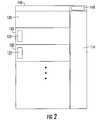
- FIGs. 1 and 2are perspective and side views, respectively, of a UPS system 100 according to some embodiments.
- the UPS system 100includes a rack or cabinet type enclosure 110.
- the enclosure 110is configured to receive and support a plurality of equipment modules in predefined slots 112.
- the modulesmay include a plurality of power converter modules 120 and a system controller 130.
- the power converter modules 120may include one or more power conversion circuits configured to provide UPS operation, such as one or more on-line UPS circuits including a cascaded combination of rectifier and inverter circuits joined by intermediate DC buses. As further illustrated, each power converter module 120 includes one or more module fan systems 122, which are configured to draw air into the module 120 and to exhaust air heated by components of the module 120 out of the rear of the module and into a plenum 114. It will be appreciated that the module fan systems 122 may vary in number and placement within the modules 120, and may include, for example, electric motor driven fans and driver electronics (e.g., motor drivers) that control operation of the fans.
- driver electronicse.g., motor drivers
- the power converter modules 120may further include control circuitry (e.g., one or more microprocessors, microcontrollers, etc.) configured to control the power conversion circuitry, the module fan systems 122 and other components of the modules 120, and to communicate with the system control module 130.
- the system control module 130may include data processing and communications circuitry configured to support control and monitoring of the power converter modules 130 and other systems mounted in the enclosure 110.
- the system control module 130may also include module fan systems similar to the module fan systems 122 of the power converter modules 120.
- the UPS system 100also includes an exhaust fan system 140 generally configured to evacuate heated air exhausted into the plenum 114 by the power converter modules 120 and/or the system controller module 130.
- the exhaust fan system 140may include one or more fans positioned in any of a variety of different ways, for example, within the enclosure 110 and/or in ductwork coupled to the enclosure 110. As shown, the exhaust fan system 140 is mounted in the enclosure 110, but it will be appreciate that, in some embodiments, the exhaust fan system 140 may be positioned exterior to the enclosure 110, such as in ductwork coupled to the enclosure 110. As discussed in detail below, in some embodiments, the exhaust fan system 140 may be controlled by the system control module 130 responsive to information related to operation of the power converter modules 120, such as power converter status information, module fan status information, and the like.
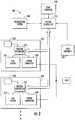
- FIG. 3is a schematic diagram illustrating apparatus and operations for fan control according to some embodiments.
- a UPS system 300includes a plurality of power converter modules 320.
- the power converter modules 320may include respective enclosures configured to be mounted in a rack or similar larger enclosure, such as the enclosure 110 described above with reference to FIGs. 1 and 2 .
- Each of the power converter modules 320includes a power converter circuit 326.
- the power converter circuit 326may include, for example, a rectifier circuit and an inverter circuit coupled by a DC buses.
- Components of the power converter circuits 326may include power semiconductor devices (e.g., IGBTs, power MOSFETs and the like), along with driver circuitry for the power semiconductor devices and associated components, such as heat sinks, temperature sensors, current sensors, voltage sensors, and the like. Inputs and/or outputs of the power converter circuits 326 of the power converter modules 322 may be configured to be paralleled
- power semiconductor devicese.g., IGBTs, power MOSFETs and the like
- driver circuitry for the power semiconductor devices and associated componentssuch as heat sinks, temperature sensors, current sensors, voltage sensors, and the like.
- Inputs and/or outputs of the power converter circuits 326 of the power converter modules 322may be configured to be paralleled
- Each power converter circuit 326is controlled by a module controller circuit 322, which may include, for example, a microcontroller, microprocessor and/or digital signal processor (DSP), and associated peripheral circuitry configured to communicate with the power converter circuit 326 to control the drive circuitry thereof.
- the module controller circuit 322may receive signals generated by the power converter circuit 326, such as signals indicating operational status, loading and/or temperature of converter components, such as temperature of heat sinks that are used to cool power semiconductor devices in the power converter circuit 326.
- Each of the power converter modules 320further includes a fan system 324, which may be configured to provide cooling air flow for the power converter circuit 326 and other components of the power converter module 320.
- the fan system 324may include one or more electric motor driven fans, along with driver circuitry (e.g., linear or pulse-width modulated driver circuits) for driving the one or more fans at variable speeds.
- the fan system 324may receive speed command signals and other operational control signals from the module controller circuit 322 and may provide signals, such as signals indicating status (e.g., failure) of the one or more fans and/or driver circuitry, to the module controller circuit 322.
- Each power converter module 326may further include additional sensors 328, such as sensors that sense temperature of ambient air taken in by the fan system 324 and/or other cooling-related parameters, such as air pressure and/or flow rate, that communicate with the module controller circuit 322.
- the module controller circuits 322 of the power converter modules 320are configured to communicate with a system controller 310 via a digital communications bus 315.
- the system controller 310may be, for example, a separate module mounted in the same enclosure as the power converter modules 320, circuitry otherwise integrated within the enclosure and/or circuitry located outside of the enclosure and electrically coupled to components within the enclosure.
- the system controller 310includes a communications circuit 312 for communicating with the power converter modules 320 via the communications bus 315.
- the system controller 310may also include control circuitry (e.g., a microprocessor or microcontroller) that may perform supervisory functions, such as monitoring operations of the power converter modules 320, controlling activation, deactivation and/or operating characteristics of the power converter modules 320, and control of other UPS system components, such as a static bypass switch and/or contactors or other switching devices used to couple the power converter module 320 to power sources and/or loads.
- the system controller 310may further include additional communications circuitry that performs external communications functions for the UPS system 300, such as Ethernet or other communications interface circuitry that supports communications with supervisory equipment that coordinates operation of the UPS system 300 with other equipment in an application environment, such as in a data center. Such interface circuitry may, for example, support Web-based or other access to the system 300.
- the system controller 310further includes a fan control circuit 312 operatively coupled to an exhaust fan system 330 configured to exhaust heated air passing out of the power converter modules and into the enclosure holding the power converter modules 320 in, for example, an arrangement such as that described above with reference to FIGs. 1 and 2 .
- the exhaust fan system 330may include one or more electric motor driven fans, along with driver circuitry (e.g., linear or pulse-width modulated driver circuits) for driving the one or more fans at variable speeds.
- the exhaust fan system 330may receive analog and/or digital speed command signals and other operational control signals from the fan control circuit 314 and may provide signals, such as signals indicating status (e.g., failure) of the one or more fans and/or driver circuitry, to the fan control circuit 314.
- the UPS system 300may further include additional system-level sensors that are interfaced to the system controller 310, such as one or more temperature sensors 340 that sense temperature of intake and/or exhaust air for the exhaust fan system 330 and/or temperatures of other parts of the enclosure environment, and load sensors 350 that sense loading of equipment served by the power converter modules 320.
- additional system-level sensorsthat are interfaced to the system controller 310, such as one or more temperature sensors 340 that sense temperature of intake and/or exhaust air for the exhaust fan system 330 and/or temperatures of other parts of the enclosure environment, and load sensors 350 that sense loading of equipment served by the power converter modules 320.
- the module controller circuits 322 in each of the power converter modules 322may independently control their respective associated fan systems 324 based on load and thermal information generated by the respective power converter modules 320.
- a module controller circuit 322may control the speed of the associated module fan system 324 using heat sink temperature, ambient air temperature and loading (e.g., current level) information received from the module-level sensors 328 and the power converter circuit 326.
- the system controller 310may control the exhaust fan system 330 based on information provided by the system level temperature and load sensors 350, as well as on status, load and temperature information obtained from the module controller circuits 322. For example, the system controller 310 may use this status, thermal and load information to minimize exhaust fan speed to reduce audible noise and/or power consumption while maintaining temperatures for the power modules 320 and other equipment in the system 300 within acceptable limits that provide a desired level of reliability.
- the system controller 310may adaptively control the exhaust fan system 330 responsive to changes in status of the power converter modules 320 using such information. For example, the system controller 310 may increase exhaust fan speed in response to receiving information from the modules 320 that indicates increased module loading, increased heat sink or ambient air temperature and/or failure of a module fan system 324.
- a system controller along the lines described abovemay also control an inlet fan system and/or an exhaust fan system based on operational modes of power converter modules.
- a UPS system 400includes a plurality of power converter modules 420. As shown, each module 420 has an on-line UPS architecture including a rectifier circuit 422 coupled to an inverter circuit 424.
- the UPS system 400may also include at least one bypass switch 430 configured to bypass the rectifier and inverter circuits 422, 424. It will be understood that the at least one bypass switch 430 may be separate from the power converter modules 420 or may be incorporated as multiple switches, respective ones of which are included in or associated with respective ones of the modules 420 in a distributed bypass arrangement.
- the at least one bypass switch 430may be closed to bypass the rectifier and inverter circuits 422, 424 in various operational modes. For example, if one or more of the rectifier circuits 422 or inverter circuits 422 experiences a failure, the system controller 410 may close the at least one bypass switch 430 and deactivate the converter circuits in the modules 420, such that the load is served via the at least on bypass switch 430.
- the system controller 410may also close the at least one bypass switch 430 and place the converter circuitry of the power converter modules 420 in a standby state to transition the system 400 to a "high efficiency" mode in which power is delivered via the at least one bypass switch 430 to reduce converter-related losses.
- certain quality criteriae.g., voltage, frequency, harmonic content, etc.
- the system controller 410may, for example, reduce the speed of the exhaust fan system 440 and/or fan systems of the power converter modules 420 due to an anticipated reduced thermal output of the modules 420, thus potentially reducing power consumption by the exhaust fan system 440 and/or the module fan systems and augmenting power savings obtained by bypass the converter circuitry.
- the adaptation of the exhaust fan speedmay also reduce ambient noise level in the data center or other environment in which the system is operating.
Landscapes
- Engineering & Computer Science (AREA)
- Microelectronics & Electronic Packaging (AREA)
- Physics & Mathematics (AREA)
- Thermal Sciences (AREA)
- Aviation & Aerospace Engineering (AREA)
- Cooling Or The Like Of Electrical Apparatus (AREA)
- Inverter Devices (AREA)
Description
- The inventive subject matter relates to electronic systems and, more particularly, to cooling systems and methods for electronic systems.
- In data centers, telecommunications centers and the like, such equipment is typically mounted in standardized enclosures (e.g., "racks") that may be arranged in rows. Such enclosures may have slots configured to be loaded with modular components, such as servers, routers, hubs and the like, that perform various computing and communications functions. Because electronic equipment may generate significant amounts of heat, cooling systems are often required to prevent equipment malfunction or failure. The equipment and/or the enclosures may be equipped with fans or other air moving devices to provide such cooling. Additional cooling may be provided by duct systems that evacuate heated air from racks using fans in conjunction with various types of exhaust ductwork coupled to the racks. Various cooling system arrangements are described, for example, in a brochure entitledAirflow Management Solutions, published by Eaton Corporation (2011).
- Rack mounted uninterruptible power supply (UPS) systems are commonly used in data center applications. Such systems may include multiple power converter modules mounted in one or more enclosures. The power converter modules may include integral cooling fans that, for example, draw air into the module and across heat-generating components and exhaust heated air through, for example, a back wall of the module. There is an ongoing need for improved cooling to enable increased power density, reduction in footprint and increased implementation flexibility of these UPS systems.
- Attention is drawn to
US 2010 102 636 A1 , which relates to an uninterruptible power supply (UPS) system including at least three UPSs configured to be connected in parallel to a common load. The system further includes control circuitry configured to support at least two redundant groups among the UPSs and to support at least two redundant subgroups among at least one of the redundant groups of UPSs, to provide a nested redundancy. - Further,
EP 1 566 086 A2 relates to an exhaust air removal system and method for use with a rack or enclosure containing equipment. The system and method are configured for removal of exhaust air vented from equipment during operation to thereby remove heat from the equipment. In one aspect, the system includes a fan unit preferably configured to serve as a back door of an equipment rack or enclosure and configured to provide access to an interior of the rack or enclosure. The fan unit provides multiple fans coupled to internal exhaust ducts that are arranged to draw and to remove exhaust air vented from rack-mounted equipment. The fan unit is further configured to vent exhaust air to an area external to a rack or enclosure, such as an external exhaust duct or plenum. - In accordance with the present invention, an UPS System, a system and a method as set forth in claims 1 and 9, respectively, are provided. Further embodiments are inter alia disclosed in the dependent claims. Some embodiments of the inventive subject matter provide an uninterruptible power supply (UPS) system including an enclosure and a plurality of power converter modules positioned in the enclosure, each power conversion module including a power converter circuit, a module controller circuit configured to control the power converter circuit and at least one module fan controlled by the module controller circuit. The system further includes a system controller positioned in the enclosure and configured to communicate with the module controller circuits over a communications bus, and at least one exhaust fan configured to exhaust air from the enclosure and controlled by the system controller. The system controller is configured to control the at least one exhaust fan responsive to information received from the module controller circuits. The system controller may also be configured to control static switches and other UPS system components.
- In some embodiments, the power converter modules may be configured to generate module temperature information. The module controller circuits may be configured to control speeds of the module fans responsive to the module temperature information. The module controller circuits may be configured to communicate the module temperature information to the system controller and the system controller may be configured to control a speed of the at least one exhaust fan responsive to the module temperature information. The module temperature information may include ambient intake air temperature information and/or heat sink temperature information.
- In some embodiments, the power converter modules may be configured to generate module load information and the module controller circuits may be configured to control speeds of the module fans responsive to the module load information. The module controller circuits may be configured to communicate the module load information to the system controller and the system controller may be configured to control a speed of the at least one exhaust fan responsive to the module load information.
- In further embodiments, the power converter modules may be configured to generate module status information and the module controller circuits may be configured to control speeds of the module fans responsive to the module status information. The module controller circuits may be configured to communicate the module status information to the system controller and the system controller may be configured to control a speed of the at least one exhaust fan responsive to the module status information. The module status information may include power converter circuit status information and/or module fan status information. The module fan status information may include module fan failure information.
- The UPS system may further include at least one sensor positioned in the enclosure apart from the power converter modules. The system controller may be further configured to control the at least one exhaust fan responsive to the at least one sensor. The at least one sensor may be configured, for example, to sense a temperature and/or a load.
- Some embodiments of the inventive subject matter provide a system including a communications circuit configured to receive module status information, module temperature information and/or module load information via a communications bus from a plurality of power converter modules mounted in a common enclosure. The system further includes a fan control circuit configured to control at least one exhaust fan that exhausts air from the enclosure responsive to the module status information, module temperature information and/or module load information received from the power converter modules. The fan control circuit may be configured to vary a speed of the at least one exhaust fan responsive to the module status information, module temperature information and/or module load information received from the power converter modules. The module temperature information may include ambient air intake temperature information and/or power converter heat sink temperature information. The module status information may include power converter circuit status information and/or module fan status information, such as module fan failure information.
- The system may further include the enclosure, and the communications circuit and the control circuit may be positioned in the enclosure. The system may also include the at least one exhaust fan.
- Still further embodiments provide methods of operating a UPS system including a plurality of power converter modules mounted in a common enclosure. The methods include respective ones of the power converter modules independently controlling respective cooling fans thereof responsive to temperature and/or load information for the respective power converter modules and a system controller of the UPS system receiving module status information, module temperature information and/or module load information from the power converter modules and responsively controlling at least one exhaust fan that exhausts air from the enclosure.
FIG. 1 is a perspective view of a UPS system according some embodiments;FIG. 2 is a side view of the UPS system ofFIG. 1 ;FIG. 3 is a schematic diagram of a UPS system with a fan control subsystem according to some embodiments; andFIG. 4 is a schematic diagram of UPS system with a fan control subsystem according to further embodiments.- Specific exemplary embodiments of the inventive subject matter now will be described with reference to the accompanying drawings. This inventive subject matter may, however, be embodied in many different forms and should not be construed as limited to the embodiments set forth herein; rather, these embodiments are provided so that this disclosure will be thorough and complete. The scope of the invention is defined by the appended claims. In the drawings, like numbers refer to like elements. It will be understood that when an element is referred to as being "connected" or "coupled" to another element, it can be directly connected or coupled to the other element or intervening elements may be present. As used herein the term "and/or" includes any and all combinations of one or more of the associated listed items.
- The terminology used herein is for the purpose of describing particular embodiments only and is not intended to be limiting of the inventive subject matter. As used herein, the singular forms "a", "an" and "the" are intended to include the plural forms as well, unless expressly stated otherwise. It will be further understood that the terms "includes," "comprises," "including" and/or "comprising," when used in this specification, specify the presence of stated features, integers, steps, operations, elements, and/or components, but do not preclude the presence or addition of one or more other features, integers, steps, operations, elements, components, and/or groups thereof.
- Unless otherwise defined, all terms (including technical and scientific terms) used herein have the same meaning as commonly understood by one of ordinary skill in the art to which this inventive subject matter belongs. It will be further understood that terms, such as those defined in commonly used dictionaries, should be interpreted as having a meaning that is consistent with their meaning in the context of the specification and the relevant art and will not be interpreted in an idealized or overly formal sense unless expressly so defined herein.
FIGs. 1 and2 are perspective and side views, respectively, of aUPS system 100 according to some embodiments. TheUPS system 100 includes a rack orcabinet type enclosure 110. Theenclosure 110 is configured to receive and support a plurality of equipment modules inpredefined slots 112. As shown, the modules may include a plurality ofpower converter modules 120 and asystem controller 130.- The
power converter modules 120 may include one or more power conversion circuits configured to provide UPS operation, such as one or more on-line UPS circuits including a cascaded combination of rectifier and inverter circuits joined by intermediate DC buses. As further illustrated, eachpower converter module 120 includes one or moremodule fan systems 122, which are configured to draw air into themodule 120 and to exhaust air heated by components of themodule 120 out of the rear of the module and into aplenum 114. It will be appreciated that themodule fan systems 122 may vary in number and placement within themodules 120, and may include, for example, electric motor driven fans and driver electronics (e.g., motor drivers) that control operation of the fans. Thepower converter modules 120 may further include control circuitry (e.g., one or more microprocessors, microcontrollers, etc.) configured to control the power conversion circuitry, themodule fan systems 122 and other components of themodules 120, and to communicate with thesystem control module 130. Thesystem control module 130 may include data processing and communications circuitry configured to support control and monitoring of thepower converter modules 130 and other systems mounted in theenclosure 110. Thesystem control module 130 may also include module fan systems similar to themodule fan systems 122 of thepower converter modules 120. - As further illustrated, the
UPS system 100 also includes anexhaust fan system 140 generally configured to evacuate heated air exhausted into theplenum 114 by thepower converter modules 120 and/or thesystem controller module 130. Theexhaust fan system 140 may include one or more fans positioned in any of a variety of different ways, for example, within theenclosure 110 and/or in ductwork coupled to theenclosure 110. As shown, theexhaust fan system 140 is mounted in theenclosure 110, but it will be appreciate that, in some embodiments, theexhaust fan system 140 may be positioned exterior to theenclosure 110, such as in ductwork coupled to theenclosure 110. As discussed in detail below, in some embodiments, theexhaust fan system 140 may be controlled by thesystem control module 130 responsive to information related to operation of thepower converter modules 120, such as power converter status information, module fan status information, and the like. FIG. 3 is a schematic diagram illustrating apparatus and operations for fan control according to some embodiments. AUPS system 300 includes a plurality ofpower converter modules 320. Thepower converter modules 320 may include respective enclosures configured to be mounted in a rack or similar larger enclosure, such as theenclosure 110 described above with reference toFIGs. 1 and2 . Each of thepower converter modules 320 includes apower converter circuit 326. Thepower converter circuit 326 may include, for example, a rectifier circuit and an inverter circuit coupled by a DC buses. Components of thepower converter circuits 326 may include power semiconductor devices (e.g., IGBTs, power MOSFETs and the like), along with driver circuitry for the power semiconductor devices and associated components, such as heat sinks, temperature sensors, current sensors, voltage sensors, and the like. Inputs and/or outputs of thepower converter circuits 326 of thepower converter modules 322 may be configured to be paralleled- Each
power converter circuit 326 is controlled by amodule controller circuit 322, which may include, for example, a microcontroller, microprocessor and/or digital signal processor (DSP), and associated peripheral circuitry configured to communicate with thepower converter circuit 326 to control the drive circuitry thereof. Themodule controller circuit 322 may receive signals generated by thepower converter circuit 326, such as signals indicating operational status, loading and/or temperature of converter components, such as temperature of heat sinks that are used to cool power semiconductor devices in thepower converter circuit 326. - Each of the
power converter modules 320 further includes afan system 324, which may be configured to provide cooling air flow for thepower converter circuit 326 and other components of thepower converter module 320. Thefan system 324 may include one or more electric motor driven fans, along with driver circuitry (e.g., linear or pulse-width modulated driver circuits) for driving the one or more fans at variable speeds. Thefan system 324 may receive speed command signals and other operational control signals from themodule controller circuit 322 and may provide signals, such as signals indicating status (e.g., failure) of the one or more fans and/or driver circuitry, to themodule controller circuit 322. Eachpower converter module 326 may further includeadditional sensors 328, such as sensors that sense temperature of ambient air taken in by thefan system 324 and/or other cooling-related parameters, such as air pressure and/or flow rate, that communicate with themodule controller circuit 322. - As further illustrated, the
module controller circuits 322 of thepower converter modules 320 are configured to communicate with asystem controller 310 via a digital communications bus 315. In various embodiments, thesystem controller 310 may be, for example, a separate module mounted in the same enclosure as thepower converter modules 320, circuitry otherwise integrated within the enclosure and/or circuitry located outside of the enclosure and electrically coupled to components within the enclosure. Thesystem controller 310 includes a communications circuit 312 for communicating with thepower converter modules 320 via the communications bus 315. Thesystem controller 310 may also include control circuitry (e.g., a microprocessor or microcontroller) that may perform supervisory functions, such as monitoring operations of thepower converter modules 320, controlling activation, deactivation and/or operating characteristics of thepower converter modules 320, and control of other UPS system components, such as a static bypass switch and/or contactors or other switching devices used to couple thepower converter module 320 to power sources and/or loads. Thesystem controller 310 may further include additional communications circuitry that performs external communications functions for theUPS system 300, such as Ethernet or other communications interface circuitry that supports communications with supervisory equipment that coordinates operation of theUPS system 300 with other equipment in an application environment, such as in a data center. Such interface circuitry may, for example, support Web-based or other access to thesystem 300. - The
system controller 310 further includes a fan control circuit 312 operatively coupled to anexhaust fan system 330 configured to exhaust heated air passing out of the power converter modules and into the enclosure holding thepower converter modules 320 in, for example, an arrangement such as that described above with reference toFIGs. 1 and2 . Theexhaust fan system 330 may include one or more electric motor driven fans, along with driver circuitry (e.g., linear or pulse-width modulated driver circuits) for driving the one or more fans at variable speeds. Theexhaust fan system 330 may receive analog and/or digital speed command signals and other operational control signals from the fan control circuit 314 and may provide signals, such as signals indicating status (e.g., failure) of the one or more fans and/or driver circuitry, to the fan control circuit 314. TheUPS system 300 may further include additional system-level sensors that are interfaced to thesystem controller 310, such as one ormore temperature sensors 340 that sense temperature of intake and/or exhaust air for theexhaust fan system 330 and/or temperatures of other parts of the enclosure environment, andload sensors 350 that sense loading of equipment served by thepower converter modules 320. - According to some embodiments, the
module controller circuits 322 in each of thepower converter modules 322 may independently control their respective associatedfan systems 324 based on load and thermal information generated by the respectivepower converter modules 320. For example, amodule controller circuit 322 may control the speed of the associatedmodule fan system 324 using heat sink temperature, ambient air temperature and loading (e.g., current level) information received from the module-level sensors 328 and thepower converter circuit 326. - The
system controller 310 may control theexhaust fan system 330 based on information provided by the system level temperature andload sensors 350, as well as on status, load and temperature information obtained from themodule controller circuits 322. For example, thesystem controller 310 may use this status, thermal and load information to minimize exhaust fan speed to reduce audible noise and/or power consumption while maintaining temperatures for thepower modules 320 and other equipment in thesystem 300 within acceptable limits that provide a desired level of reliability. Thesystem controller 310 may adaptively control theexhaust fan system 330 responsive to changes in status of thepower converter modules 320 using such information. For example, thesystem controller 310 may increase exhaust fan speed in response to receiving information from themodules 320 that indicates increased module loading, increased heat sink or ambient air temperature and/or failure of amodule fan system 324. - According to some embodiments, a system controller along the lines described above may also control an inlet fan system and/or an exhaust fan system based on operational modes of power converter modules. Referring to
FIG. 4 , aUPS system 400 includes a plurality ofpower converter modules 420. As shown, eachmodule 420 has an on-line UPS architecture including arectifier circuit 422 coupled to aninverter circuit 424. TheUPS system 400 may also include at least onebypass switch 430 configured to bypass the rectifier andinverter circuits bypass switch 430 may be separate from thepower converter modules 420 or may be incorporated as multiple switches, respective ones of which are included in or associated with respective ones of themodules 420 in a distributed bypass arrangement. - The at least one
bypass switch 430 may be closed to bypass the rectifier andinverter circuits rectifier circuits 422 orinverter circuits 422 experiences a failure, thesystem controller 410 may close the at least onebypass switch 430 and deactivate the converter circuits in themodules 420, such that the load is served via the at least onbypass switch 430. If thesystem controller 410 detects that an AC source applied to thepower converter modules 420 meets certain quality criteria (e.g., voltage, frequency, harmonic content, etc.), the system controller may also close the at least onebypass switch 430 and place the converter circuitry of thepower converter modules 420 in a standby state to transition thesystem 400 to a "high efficiency" mode in which power is delivered via the at least onebypass switch 430 to reduce converter-related losses. In response to detection either of these modes, thesystem controller 410 may, for example, reduce the speed of theexhaust fan system 440 and/or fan systems of thepower converter modules 420 due to an anticipated reduced thermal output of themodules 420, thus potentially reducing power consumption by theexhaust fan system 440 and/or the module fan systems and augmenting power savings obtained by bypass the converter circuitry. The adaptation of the exhaust fan speed may also reduce ambient noise level in the data center or other environment in which the system is operating. - It will be appreciated that the above-described adaptive fan control operations are provided as examples, and that other control regimes fall within the scope of the inventive subject matter.
- In the drawings and specification, there have been disclosed exemplary embodiments of the inventive subject matter. Although specific terms are employed, they are used in a generic and descriptive sense only and not for purposes of limitation, the scope of the inventive subject matter being defined by the following claims.
Claims (10)
- An uninterruptible power supply, UPS, system (100; 300; 400), comprising:an enclosure (110);at least one exhaust fan (140; 330; 440) configured to exhaust air from the enclosure (110);a plurality of power converter modules (120; 320; 420) positioned in the enclosure (110), each power conversion module (120; 320; 420) comprising a power converter circuit (326), at least one module fan (122; 324), and a module controller circuit (322) configured to control the power converter circuit (326) and the at least one module fan (122; 324);a system controller (130; 310; 410) positioned in the enclosure (110) and configured to receive module fan status information from the module controller circuits (322) over a communications bus (315) and to control the at least one exhaust fan (140; 330; 440) responsive to module fan status information received from the module controller circuits (322).
- The system (100; 300; 400) of claim 1, wherein the power converter modules (120; 320; 420) are configured to generate module temperature information and wherein the module controller circuits (322) are configured to control speeds of the module fans (122; 324) responsive to the module temperature information.
- The system (100; 300; 400) of claim 2, wherein the module controller circuits (322) are configured to communicate the module temperature information to the system controller (130; 310; 410) and wherein the system controller (130; 310; 410) is configured to control a speed of the at least one exhaust fan (140; 330; 440) responsive to the module temperature information.
- The system (100; 300; 400) of claim 1, wherein the power converter modules (120; 320; 420) are configured to generate module load information and wherein the module controller circuits (322) are configured to control speeds of the module fans (122; 324) responsive to the module load information.
- The system (100; 300; 400) of claim 4, wherein the module controller circuits (322) are configured to communicate the module load information to the system controller (130; 310; 410) and wherein the system controller (130; 310; 410) is configured to control a speed of the at least one exhaust fan (140; 330; 440) responsive to the module load information.
- The system (100; 300; 400) of claim 1, wherein the power converter modules (120; 320; 420) are configured to generate module status information and wherein the module controller circuits (322) are configured to control speeds of the module fans (122; 324) responsive to the module status information.
- The system (100; 300; 400) of claim 6, wherein the module controller circuits (322) are configured to communicate the module status information to the system controller (130; 310; 410) and wherein the system controller (130; 310; 410) is configured to control a speed of the at least one exhaust fan (140; 330; 440) responsive to the module status information.
- The system (100; 300; 400) of claim 1, further comprising at least one sensor positioned in the enclosure (110) apart from the power converter modules (120; 320; 420), and wherein the system controller (130; 310; 410) is further configured to control the at least one exhaust fan (140; 330; 440) responsive to the at least one sensor.
- A method of operating a UPS system according to the claim 1, the method comprising:respective module controller circuits (322) of respective ones of the power converter modules (120; 320; 420) independently controlling respective power converter circuits (326) and respective cooling fans (122; 324) thereof responsive to temperature and/or load information for the respective power converter modules (120; 320; 420); anda system controller (130; 310; 410) of the UPS system receiving control and status information for the power converter circuits (326) and the cooling fans (122; 324) from the module controller circuits (322) of the power converter modules (120; 320; 420) and responsively controlling at least one exhaust fan (140; 330; 440) that exhausts air from the enclosure (110).
- The method of claim 9, wherein the system controller (130; 310; 410) of the UPS system receiving control and status information for the power converter circuits (326) and the cooling fans (122; 324) from the module controller circuits (322) of the power converter modules (120; 320; 420) and responsively controlling at least one exhaust fan (140; 330; 440) that exhausts air from the enclosure (110) comprises varying a speed of the at least one exhaust fan (140; 330; 440).
Applications Claiming Priority (1)
| Application Number | Priority Date | Filing Date | Title |
|---|---|---|---|
| PCT/CN2012/085468WO2014082229A1 (en) | 2012-11-28 | 2012-11-28 | Equipment enclosure fan control systems and methods |
Publications (3)
| Publication Number | Publication Date |
|---|---|
| EP2926633A1 EP2926633A1 (en) | 2015-10-07 |
| EP2926633A4 EP2926633A4 (en) | 2016-07-27 |
| EP2926633B1true EP2926633B1 (en) | 2021-05-19 |
Family
ID=50827037
Family Applications (1)
| Application Number | Title | Priority Date | Filing Date |
|---|---|---|---|
| EP12889342.7AActiveEP2926633B1 (en) | 2012-11-28 | 2012-11-28 | Equipment enclosure fan control systems and methods |
Country Status (4)
| Country | Link |
|---|---|
| US (1) | US11006546B2 (en) |
| EP (1) | EP2926633B1 (en) |
| CN (1) | CN105052248B (en) |
| WO (1) | WO2014082229A1 (en) |
Families Citing this family (16)
| Publication number | Priority date | Publication date | Assignee | Title |
|---|---|---|---|---|
| WO2014068651A1 (en)* | 2012-10-30 | 2014-05-08 | 株式会社三社電機製作所 | Fan control device and power conditioner |
| EP2926633B1 (en) | 2012-11-28 | 2021-05-19 | Eaton Intelligent Power Limited | Equipment enclosure fan control systems and methods |
| DE102013208552A1 (en)* | 2013-05-08 | 2014-11-13 | Lenze Drives Gmbh | drive system |
| US9936614B2 (en)* | 2015-02-11 | 2018-04-03 | Dell Products, Lp | System and method for automated open loop fan control |
| PL3088989T3 (en)* | 2015-04-30 | 2018-08-31 | Abb Schweiz Ag | Ups operation with high converter efficiency |
| JP6316777B2 (en)* | 2015-07-21 | 2018-04-25 | ファナック株式会社 | Motor drive device and method for detecting abnormality in heat dissipation performance of heat sink |
| US10404097B2 (en)* | 2016-01-07 | 2019-09-03 | Cisco Technology, Inc. | Multi-input line-redundant uninterruptable power supply |
| US20200278726A1 (en)* | 2016-01-08 | 2020-09-03 | Hewlett Packard Enterprise Development Lp | Power supply fan |
| CN106229003B (en)* | 2016-08-31 | 2018-09-18 | 浙江大华技术股份有限公司 | The method and device of radiating fan rotation speed in a kind of adjustment storage device |
| US11801639B2 (en)* | 2017-07-28 | 2023-10-31 | Hewlett-Packard Development Company, L.P. | Controlled cooling for print heads |
| JP7047400B2 (en)* | 2018-01-25 | 2022-04-05 | 富士電機株式会社 | Power converter |
| CN108488960A (en)* | 2018-05-23 | 2018-09-04 | 四川中科优联科技有限责任公司 | A kind of multi-functional intake and exhaust tower air purification system up and down based on cloud platform Internet of Things |
| CN110504743A (en)* | 2019-08-12 | 2019-11-26 | 合肥通用电源设备有限公司 | A kind of portable ups power cabinet |
| CN112524062B (en)* | 2019-09-19 | 2022-11-25 | 台达电子工业股份有限公司 | Heat dissipation device with energy-saving effect and control method thereof |
| US11355956B1 (en)* | 2020-12-08 | 2022-06-07 | Schneider Electric It Corporation | High-efficiency modular uninterruptible power supply |
| CN112959910A (en)* | 2021-04-13 | 2021-06-15 | 上海Abb联桩新能源技术有限公司 | High-power charging system based on isolation air duct type heat exchange |
Family Cites Families (60)
| Publication number | Priority date | Publication date | Assignee | Title |
|---|---|---|---|---|
| US4903685A (en) | 1989-01-24 | 1990-02-27 | Melink Stephen K | Variable exhaust controller for commercial kitchens |
| JP3232908B2 (en)* | 1994-09-20 | 2001-11-26 | 株式会社日立製作所 | Electronic equipment |
| DE19723955A1 (en) | 1996-06-12 | 1998-03-26 | Denso Corp | Cooling device, boiling and condensing refrigerant, for electronic component in closed box |
| US6037732A (en) | 1996-11-14 | 2000-03-14 | Telcom Semiconductor, Inc. | Intelligent power management for a variable speed fan |
| US6324608B1 (en)* | 1997-05-13 | 2001-11-27 | Micron Electronics | Method for hot swapping of network components |
| US6127663A (en)* | 1998-10-09 | 2000-10-03 | Ericsson Inc. | Electronics cabinet cooling system |
| US6142866A (en)* | 1999-03-18 | 2000-11-07 | Nokia Telecommunications, Oy | Method and apparatus for providing air circulation control for a base transceiver station |
| JP2000346512A (en)* | 1999-06-03 | 2000-12-15 | Fujitsu Ltd | Cooling system |
| US6428282B1 (en)* | 1999-06-14 | 2002-08-06 | Hewlett-Packard Company | System with fan speed synchronization control |
| US6463891B2 (en) | 1999-12-17 | 2002-10-15 | Caterpillar Inc. | Twin fan control system and method |
| US6535382B2 (en)* | 2001-04-12 | 2003-03-18 | Johnson Controls Technology Company | Cooling system for electronic equipment cabinets |
| JP2003174274A (en) | 2001-12-06 | 2003-06-20 | Furukawa Electric Co Ltd:The | Outdoor cabinet |
| US6639794B2 (en)* | 2001-12-18 | 2003-10-28 | Maxxan Systems, Inc. | Chassis with adaptive fan control |
| JP2003193994A (en) | 2001-12-21 | 2003-07-09 | Namiki Precision Jewel Co Ltd | Cooling / waste heat fan device |
| US6628520B2 (en)* | 2002-02-06 | 2003-09-30 | Hewlett-Packard Development Company, L.P. | Method, apparatus, and system for cooling electronic components |
| CN1202456C (en) | 2002-09-25 | 2005-05-18 | 艾默生网络能源有限公司 | UPS fan controlling method |
| AU2003285140A1 (en)* | 2002-11-01 | 2004-06-07 | Rudy Kraus | Apparatus for providing high quality power |
| WO2004049773A2 (en) | 2002-11-25 | 2004-06-10 | American Power Conversion Corporation | Exhaust air removal system |
| US7752858B2 (en) | 2002-11-25 | 2010-07-13 | American Power Conversion Corporation | Exhaust air removal system |
| US6932696B2 (en)* | 2003-01-08 | 2005-08-23 | Sun Microsystems, Inc. | Cooling system including redundant fan controllers |
| US8237386B2 (en) | 2003-08-15 | 2012-08-07 | Apple Inc. | Methods and apparatuses for operating a data processing system |
| CN2645410Y (en)* | 2003-08-27 | 2004-09-29 | 纵横网路资讯股份有限公司 | Electronic Equipment Cabinet |
| US6936767B2 (en)* | 2003-10-14 | 2005-08-30 | Toshiba International Corporation | Apparatus for continuous cooling of electrical powered equipment |
| US7010392B2 (en)* | 2004-05-26 | 2006-03-07 | Hewlett-Packard Development Company, L.P. | Energy efficient CRAC unit operation using heat transfer levels |
| US7331532B2 (en) | 2004-06-09 | 2008-02-19 | Nortel Networks Limited | Acoustic noise reduction using fan speed control |
| KR20060004234A (en) | 2004-07-09 | 2006-01-12 | 엘지전자 주식회사 | Fan motion control device and method |
| US7249718B2 (en)* | 2004-07-20 | 2007-07-31 | Hewlett-Packard Development Company, L.P. | Cooling system with a variable maximum operation level |
| JP2006059448A (en)* | 2004-08-20 | 2006-03-02 | Hitachi Ltd | Disk array device |
| JP4673019B2 (en)* | 2004-09-10 | 2011-04-20 | 日立コンピュータ機器株式会社 | Information processing device |
| US7180738B2 (en)* | 2004-11-04 | 2007-02-20 | Teledata Networks Limited | Communication cabinet and a method for dust removal of communications cabinet filters |
| JP2006164006A (en)* | 2004-12-09 | 2006-06-22 | Hitachi Ltd | Disk array device |
| US7461273B2 (en)* | 2005-05-16 | 2008-12-02 | Hewlett-Packard Development Company, L.P. | Power distribution among servers |
| US8626918B2 (en)* | 2005-05-16 | 2014-01-07 | Hewlett-Packard Development Company, L.P. | Workload allocation based upon heat re-circulation causes |
| US7190583B1 (en)* | 2005-08-29 | 2007-03-13 | Verigy Pte Ltd | Self contained, liquid to air cooled, memory test engineering workstation |
| WO2007084423A2 (en)* | 2006-01-13 | 2007-07-26 | Sun Microsystems, Inc. | Compact rackmount server |
| US7638899B2 (en)* | 2006-03-10 | 2009-12-29 | Eaton Corporation | Nested redundant uninterruptible power supply apparatus and methods |
| JP4253850B2 (en) | 2006-07-13 | 2009-04-15 | 株式会社安川電機 | Traveling device and robot |
| US20080239666A1 (en)* | 2007-03-28 | 2008-10-02 | Adc Dsl Systems, Inc. | Fan module |
| US7714731B2 (en)* | 2007-06-22 | 2010-05-11 | Andrew Llc | Detection of air filter clogging and provision of emergency ventilation in an outdoor electronics cabinet cooled by ambient forced air |
| US20090034187A1 (en)* | 2007-07-31 | 2009-02-05 | Coles Henry C | Pressure-based fan speed adjustment |
| US7768222B2 (en)* | 2008-02-15 | 2010-08-03 | International Business Machines Corporation | Automated control of rotational velocity of an air-moving device of an electronics rack responsive to an event |
| US8904383B2 (en)* | 2008-04-10 | 2014-12-02 | Hewlett-Packard Development Company, L.P. | Virtual machine migration according to environmental data |
| WO2010031029A1 (en) | 2008-09-15 | 2010-03-18 | General Electric Company | Energy management of clothes dryer appliance |
| CN201260293Y (en) | 2008-09-23 | 2009-06-17 | 广东易事特电源股份有限公司 | Air duct structure of power supply internal functional module |
| WO2010054786A1 (en) | 2008-11-14 | 2010-05-20 | Knürr AG | Method for cooling-air regulation in equipment cabinets and sensor arrangement |
| US8120300B2 (en) | 2008-12-30 | 2012-02-21 | International Business Machines Corporation | Fault tolerant cooling in a redundant power system |
| US8270154B2 (en) | 2009-01-27 | 2012-09-18 | Microsoft Corporation | Self-contained and modular air-cooled containerized server cooling |
| CN101847940B (en) | 2009-03-24 | 2012-07-18 | 深圳市英威腾电气股份有限公司 | Assembly structure of inverter power unit and modular power unit using same |
| CN102052338A (en)* | 2009-11-10 | 2011-05-11 | 英业达股份有限公司 | Server framework and fan system thereof |
| GB2478779B (en) | 2010-03-19 | 2017-04-12 | Ebm-Papst Uk Ltd | Independent fan speed control |
| US20110266229A1 (en)* | 2010-04-30 | 2011-11-03 | M&A Technology, Inc. | Stackable modular personal computer array |
| CN201699443U (en) | 2010-05-21 | 2011-01-05 | 深圳科士达科技股份有限公司 | A moisture-proof UPS cabinet |
| CN102458084B (en)* | 2010-10-29 | 2016-05-11 | 鸿富锦精密工业(深圳)有限公司 | Data center and cooling system thereof |
| CN202103439U (en) | 2010-12-30 | 2012-01-04 | 深圳科士达科技股份有限公司 | UPS outdoor integrated machine |
| CN202468388U (en) | 2012-01-13 | 2012-10-03 | 百度在线网络技术(北京)有限公司 | Radiating system for data center |
| JP5979244B2 (en)* | 2012-11-16 | 2016-08-24 | 富士通株式会社 | Modular data center and its control method |
| EP2926633B1 (en) | 2012-11-28 | 2021-05-19 | Eaton Intelligent Power Limited | Equipment enclosure fan control systems and methods |
| JP6037021B2 (en)* | 2013-09-06 | 2016-11-30 | アラクサラネットワークス株式会社 | Communication apparatus and communication system |
| US9820411B2 (en)* | 2013-10-10 | 2017-11-14 | Lenovo Enterprise Solutions (Singapore) Pte. Ltd. | Reversible fan direction control responsive to device enclosure orientation |
| US9901007B1 (en)* | 2015-04-30 | 2018-02-20 | Juniper Networks, Inc. | Removable board with cooling system for chassis-based electronic equipment |
- 2012
- 2012-11-28EPEP12889342.7Apatent/EP2926633B1/enactiveActive
- 2012-11-28CNCN201280077143.1Apatent/CN105052248B/enactiveActive
- 2012-11-28USUS14/646,855patent/US11006546B2/enactiveActive
- 2012-11-28WOPCT/CN2012/085468patent/WO2014082229A1/enactiveApplication Filing
Non-Patent Citations (1)
| Title |
|---|
| None* |
Also Published As
| Publication number | Publication date |
|---|---|
| US11006546B2 (en) | 2021-05-11 |
| CN105052248B (en) | 2017-08-08 |
| EP2926633A1 (en) | 2015-10-07 |
| WO2014082229A1 (en) | 2014-06-05 |
| US20150305197A1 (en) | 2015-10-22 |
| EP2926633A4 (en) | 2016-07-27 |
| CN105052248A (en) | 2015-11-11 |
Similar Documents
| Publication | Publication Date | Title |
|---|---|---|
| EP2926633B1 (en) | Equipment enclosure fan control systems and methods | |
| US6639794B2 (en) | Chassis with adaptive fan control | |
| US8325479B2 (en) | Motor drive cooling duct system and method | |
| US8325478B2 (en) | Cooling duct attachment and sealing for a motor drive | |
| US9084376B2 (en) | Heat sink cooling arrangement for multiple power electronic circuits | |
| US20060120001A1 (en) | Modular power supply assembly | |
| US20090109619A1 (en) | Method apparatus for cooling system having an s-shaped air flow path for use in a chassis | |
| US8587929B2 (en) | High density uninterruptible power supplies and related systems and power distribution units | |
| US7768222B2 (en) | Automated control of rotational velocity of an air-moving device of an electronics rack responsive to an event | |
| US7715215B1 (en) | Control of an AC-to-DC power supply assembly fed by a three-phase AC source | |
| US20140138068A1 (en) | Cooling System | |
| US20130170134A1 (en) | Server system with fan speed control and servers thereof | |
| US20240414878A1 (en) | Electronic device and heat dissipation method therefor | |
| US20040017654A1 (en) | External fan and method for exchanging air with modular bricks in a computer system | |
| US20120024515A1 (en) | Data center and heat dissipating system thereof | |
| EP3270455B1 (en) | Battery storage system with integrated inverter | |
| JP2005257258A (en) | Fan filter unit | |
| US20070148019A1 (en) | Method and device for connecting several types of fans | |
| CN108150442B (en) | Cabinet fan control method and module | |
| CN112821474B (en) | Power supply system, network device and power supply control method | |
| CN109936326B (en) | Motor drive device and motor drive system | |
| US20200373813A1 (en) | Integrated Motor Electronics | |
| CN103457179B (en) | Power supply cabinet | |
| US20240407128A1 (en) | Method for controlling fan speed, and electronic device | |
| JP2000228593A (en) | Uninterruptible power supply cooling structure |
Legal Events
| Date | Code | Title | Description |
|---|---|---|---|
| PUAI | Public reference made under article 153(3) epc to a published international application that has entered the european phase | Free format text:ORIGINAL CODE: 0009012 | |
| 17P | Request for examination filed | Effective date:20150526 | |
| AK | Designated contracting states | Kind code of ref document:A1 Designated state(s):AL AT BE BG CH CY CZ DE DK EE ES FI FR GB GR HR HU IE IS IT LI LT LU LV MC MK MT NL NO PL PT RO RS SE SI SK SM TR | |
| AX | Request for extension of the european patent | Extension state:BA ME | |
| DAX | Request for extension of the european patent (deleted) | ||
| RA4 | Supplementary search report drawn up and despatched (corrected) | Effective date:20160623 | |
| RIC1 | Information provided on ipc code assigned before grant | Ipc:H05K 7/20 20060101AFI20160617BHEP | |
| RAP1 | Party data changed (applicant data changed or rights of an application transferred) | Owner name:EATON CORPORATION | |
| STAA | Information on the status of an ep patent application or granted ep patent | Free format text:STATUS: EXAMINATION IS IN PROGRESS | |
| 17Q | First examination report despatched | Effective date:20190325 | |
| RAP1 | Party data changed (applicant data changed or rights of an application transferred) | Owner name:EATON INTELLIGENT POWER LIMITED | |
| GRAP | Despatch of communication of intention to grant a patent | Free format text:ORIGINAL CODE: EPIDOSNIGR1 | |
| STAA | Information on the status of an ep patent application or granted ep patent | Free format text:STATUS: GRANT OF PATENT IS INTENDED | |
| INTG | Intention to grant announced | Effective date:20210112 | |
| GRAS | Grant fee paid | Free format text:ORIGINAL CODE: EPIDOSNIGR3 | |
| GRAA | (expected) grant | Free format text:ORIGINAL CODE: 0009210 | |
| STAA | Information on the status of an ep patent application or granted ep patent | Free format text:STATUS: THE PATENT HAS BEEN GRANTED | |
| AK | Designated contracting states | Kind code of ref document:B1 Designated state(s):AL AT BE BG CH CY CZ DE DK EE ES FI FR GB GR HR HU IE IS IT LI LT LU LV MC MK MT NL NO PL PT RO RS SE SI SK SM TR | |
| REG | Reference to a national code | Ref country code:GB Ref legal event code:FG4D | |
| REG | Reference to a national code | Ref country code:CH Ref legal event code:EP | |
| REG | Reference to a national code | Ref country code:DE Ref legal event code:R096 Ref document number:602012075643 Country of ref document:DE | |
| REG | Reference to a national code | Ref country code:AT Ref legal event code:REF Ref document number:1395270 Country of ref document:AT Kind code of ref document:T Effective date:20210615 | |
| REG | Reference to a national code | Ref country code:IE Ref legal event code:FG4D | |
| REG | Reference to a national code | Ref country code:LT Ref legal event code:MG9D | |
| REG | Reference to a national code | Ref country code:AT Ref legal event code:MK05 Ref document number:1395270 Country of ref document:AT Kind code of ref document:T Effective date:20210519 | |
| REG | Reference to a national code | Ref country code:NL Ref legal event code:MP Effective date:20210519 | |
| PG25 | Lapsed in a contracting state [announced via postgrant information from national office to epo] | Ref country code:AT Free format text:LAPSE BECAUSE OF FAILURE TO SUBMIT A TRANSLATION OF THE DESCRIPTION OR TO PAY THE FEE WITHIN THE PRESCRIBED TIME-LIMIT Effective date:20210519 Ref country code:BG Free format text:LAPSE BECAUSE OF FAILURE TO SUBMIT A TRANSLATION OF THE DESCRIPTION OR TO PAY THE FEE WITHIN THE PRESCRIBED TIME-LIMIT Effective date:20210819 Ref country code:HR Free format text:LAPSE BECAUSE OF FAILURE TO SUBMIT A TRANSLATION OF THE DESCRIPTION OR TO PAY THE FEE WITHIN THE PRESCRIBED TIME-LIMIT Effective date:20210519 Ref country code:LT Free format text:LAPSE BECAUSE OF FAILURE TO SUBMIT A TRANSLATION OF THE DESCRIPTION OR TO PAY THE FEE WITHIN THE PRESCRIBED TIME-LIMIT Effective date:20210519 Ref country code:FI Free format text:LAPSE BECAUSE OF FAILURE TO SUBMIT A TRANSLATION OF THE DESCRIPTION OR TO PAY THE FEE WITHIN THE PRESCRIBED TIME-LIMIT Effective date:20210519 | |
| PG25 | Lapsed in a contracting state [announced via postgrant information from national office to epo] | Ref country code:SE Free format text:LAPSE BECAUSE OF FAILURE TO SUBMIT A TRANSLATION OF THE DESCRIPTION OR TO PAY THE FEE WITHIN THE PRESCRIBED TIME-LIMIT Effective date:20210519 Ref country code:RS Free format text:LAPSE BECAUSE OF FAILURE TO SUBMIT A TRANSLATION OF THE DESCRIPTION OR TO PAY THE FEE WITHIN THE PRESCRIBED TIME-LIMIT Effective date:20210519 Ref country code:GR Free format text:LAPSE BECAUSE OF FAILURE TO SUBMIT A TRANSLATION OF THE DESCRIPTION OR TO PAY THE FEE WITHIN THE PRESCRIBED TIME-LIMIT Effective date:20210820 Ref country code:LV Free format text:LAPSE BECAUSE OF FAILURE TO SUBMIT A TRANSLATION OF THE DESCRIPTION OR TO PAY THE FEE WITHIN THE PRESCRIBED TIME-LIMIT Effective date:20210519 Ref country code:IS Free format text:LAPSE BECAUSE OF FAILURE TO SUBMIT A TRANSLATION OF THE DESCRIPTION OR TO PAY THE FEE WITHIN THE PRESCRIBED TIME-LIMIT Effective date:20210919 Ref country code:ES Free format text:LAPSE BECAUSE OF FAILURE TO SUBMIT A TRANSLATION OF THE DESCRIPTION OR TO PAY THE FEE WITHIN THE PRESCRIBED TIME-LIMIT Effective date:20210519 Ref country code:PT Free format text:LAPSE BECAUSE OF FAILURE TO SUBMIT A TRANSLATION OF THE DESCRIPTION OR TO PAY THE FEE WITHIN THE PRESCRIBED TIME-LIMIT Effective date:20210920 Ref country code:NO Free format text:LAPSE BECAUSE OF FAILURE TO SUBMIT A TRANSLATION OF THE DESCRIPTION OR TO PAY THE FEE WITHIN THE PRESCRIBED TIME-LIMIT Effective date:20210819 Ref country code:PL Free format text:LAPSE BECAUSE OF FAILURE TO SUBMIT A TRANSLATION OF THE DESCRIPTION OR TO PAY THE FEE WITHIN THE PRESCRIBED TIME-LIMIT Effective date:20210519 | |
| PG25 | Lapsed in a contracting state [announced via postgrant information from national office to epo] | Ref country code:NL Free format text:LAPSE BECAUSE OF FAILURE TO SUBMIT A TRANSLATION OF THE DESCRIPTION OR TO PAY THE FEE WITHIN THE PRESCRIBED TIME-LIMIT Effective date:20210519 | |
| PG25 | Lapsed in a contracting state [announced via postgrant information from national office to epo] | Ref country code:EE Free format text:LAPSE BECAUSE OF FAILURE TO SUBMIT A TRANSLATION OF THE DESCRIPTION OR TO PAY THE FEE WITHIN THE PRESCRIBED TIME-LIMIT Effective date:20210519 Ref country code:DK Free format text:LAPSE BECAUSE OF FAILURE TO SUBMIT A TRANSLATION OF THE DESCRIPTION OR TO PAY THE FEE WITHIN THE PRESCRIBED TIME-LIMIT Effective date:20210519 Ref country code:CZ Free format text:LAPSE BECAUSE OF FAILURE TO SUBMIT A TRANSLATION OF THE DESCRIPTION OR TO PAY THE FEE WITHIN THE PRESCRIBED TIME-LIMIT Effective date:20210519 Ref country code:SM Free format text:LAPSE BECAUSE OF FAILURE TO SUBMIT A TRANSLATION OF THE DESCRIPTION OR TO PAY THE FEE WITHIN THE PRESCRIBED TIME-LIMIT Effective date:20210519 Ref country code:SK Free format text:LAPSE BECAUSE OF FAILURE TO SUBMIT A TRANSLATION OF THE DESCRIPTION OR TO PAY THE FEE WITHIN THE PRESCRIBED TIME-LIMIT Effective date:20210519 Ref country code:RO Free format text:LAPSE BECAUSE OF FAILURE TO SUBMIT A TRANSLATION OF THE DESCRIPTION OR TO PAY THE FEE WITHIN THE PRESCRIBED TIME-LIMIT Effective date:20210519 | |
| REG | Reference to a national code | Ref country code:DE Ref legal event code:R097 Ref document number:602012075643 Country of ref document:DE | |
| PLBE | No opposition filed within time limit | Free format text:ORIGINAL CODE: 0009261 | |
| STAA | Information on the status of an ep patent application or granted ep patent | Free format text:STATUS: NO OPPOSITION FILED WITHIN TIME LIMIT | |
| 26N | No opposition filed | Effective date:20220222 | |
| PG25 | Lapsed in a contracting state [announced via postgrant information from national office to epo] | Ref country code:IS Free format text:LAPSE BECAUSE OF FAILURE TO SUBMIT A TRANSLATION OF THE DESCRIPTION OR TO PAY THE FEE WITHIN THE PRESCRIBED TIME-LIMIT Effective date:20210919 Ref country code:AL Free format text:LAPSE BECAUSE OF FAILURE TO SUBMIT A TRANSLATION OF THE DESCRIPTION OR TO PAY THE FEE WITHIN THE PRESCRIBED TIME-LIMIT Effective date:20210519 | |
| PG25 | Lapsed in a contracting state [announced via postgrant information from national office to epo] | Ref country code:MC Free format text:LAPSE BECAUSE OF FAILURE TO SUBMIT A TRANSLATION OF THE DESCRIPTION OR TO PAY THE FEE WITHIN THE PRESCRIBED TIME-LIMIT Effective date:20210519 | |
| REG | Reference to a national code | Ref country code:CH Ref legal event code:PL | |
| PG25 | Lapsed in a contracting state [announced via postgrant information from national office to epo] | Ref country code:LU Free format text:LAPSE BECAUSE OF NON-PAYMENT OF DUE FEES Effective date:20211128 Ref country code:IT Free format text:LAPSE BECAUSE OF FAILURE TO SUBMIT A TRANSLATION OF THE DESCRIPTION OR TO PAY THE FEE WITHIN THE PRESCRIBED TIME-LIMIT Effective date:20210519 Ref country code:BE Free format text:LAPSE BECAUSE OF NON-PAYMENT OF DUE FEES Effective date:20211130 | |
| REG | Reference to a national code | Ref country code:BE Ref legal event code:MM Effective date:20211130 | |
| PG25 | Lapsed in a contracting state [announced via postgrant information from national office to epo] | Ref country code:IE Free format text:LAPSE BECAUSE OF NON-PAYMENT OF DUE FEES Effective date:20211128 | |
| PG25 | Lapsed in a contracting state [announced via postgrant information from national office to epo] | Ref country code:HU Free format text:LAPSE BECAUSE OF FAILURE TO SUBMIT A TRANSLATION OF THE DESCRIPTION OR TO PAY THE FEE WITHIN THE PRESCRIBED TIME-LIMIT; INVALID AB INITIO Effective date:20121128 Ref country code:CY Free format text:LAPSE BECAUSE OF FAILURE TO SUBMIT A TRANSLATION OF THE DESCRIPTION OR TO PAY THE FEE WITHIN THE PRESCRIBED TIME-LIMIT Effective date:20210519 | |
| P01 | Opt-out of the competence of the unified patent court (upc) registered | Effective date:20230521 | |
| PG25 | Lapsed in a contracting state [announced via postgrant information from national office to epo] | Ref country code:LI Free format text:LAPSE BECAUSE OF NON-PAYMENT OF DUE FEES Effective date:20220701 Ref country code:CH Free format text:LAPSE BECAUSE OF NON-PAYMENT OF DUE FEES Effective date:20220701 | |
| PG25 | Lapsed in a contracting state [announced via postgrant information from national office to epo] | Ref country code:MK Free format text:LAPSE BECAUSE OF FAILURE TO SUBMIT A TRANSLATION OF THE DESCRIPTION OR TO PAY THE FEE WITHIN THE PRESCRIBED TIME-LIMIT Effective date:20210519 | |
| PG25 | Lapsed in a contracting state [announced via postgrant information from national office to epo] | Ref country code:TR Free format text:LAPSE BECAUSE OF FAILURE TO SUBMIT A TRANSLATION OF THE DESCRIPTION OR TO PAY THE FEE WITHIN THE PRESCRIBED TIME-LIMIT Effective date:20210519 | |
| PG25 | Lapsed in a contracting state [announced via postgrant information from national office to epo] | Ref country code:MT Free format text:LAPSE BECAUSE OF FAILURE TO SUBMIT A TRANSLATION OF THE DESCRIPTION OR TO PAY THE FEE WITHIN THE PRESCRIBED TIME-LIMIT Effective date:20210519 | |
| PGFP | Annual fee paid to national office [announced via postgrant information from national office to epo] | Ref country code:DE Payment date:20241022 Year of fee payment:13 | |
| PGFP | Annual fee paid to national office [announced via postgrant information from national office to epo] | Ref country code:GB Payment date:20241023 Year of fee payment:13 | |
| PGFP | Annual fee paid to national office [announced via postgrant information from national office to epo] | Ref country code:FR Payment date:20241022 Year of fee payment:13 |