EP2926470B1 - Reconfigurable single and multi-sector cell site system - Google Patents
Reconfigurable single and multi-sector cell site systemDownload PDFInfo
- Publication number
- EP2926470B1 EP2926470B1EP13826606.9AEP13826606AEP2926470B1EP 2926470 B1EP2926470 B1EP 2926470B1EP 13826606 AEP13826606 AEP 13826606AEP 2926470 B1EP2926470 B1EP 2926470B1
- Authority
- EP
- European Patent Office
- Prior art keywords
- phase
- cell site
- signal
- signals
- antenna sub
- Prior art date
- Legal status (The legal status is an assumption and is not a legal conclusion. Google has not performed a legal analysis and makes no representation as to the accuracy of the status listed.)
- Active
Links
Images


Classifications
- H—ELECTRICITY
- H04—ELECTRIC COMMUNICATION TECHNIQUE
- H04W—WIRELESS COMMUNICATION NETWORKS
- H04W16/00—Network planning, e.g. coverage or traffic planning tools; Network deployment, e.g. resource partitioning or cells structures
- H04W16/24—Cell structures
- H04W16/28—Cell structures using beam steering
- H—ELECTRICITY
- H04—ELECTRIC COMMUNICATION TECHNIQUE
- H04B—TRANSMISSION
- H04B7/00—Radio transmission systems, i.e. using radiation field
- H04B7/02—Diversity systems; Multi-antenna system, i.e. transmission or reception using multiple antennas
- H04B7/04—Diversity systems; Multi-antenna system, i.e. transmission or reception using multiple antennas using two or more spaced independent antennas
- H04B7/0491—Diversity systems; Multi-antenna system, i.e. transmission or reception using multiple antennas using two or more spaced independent antennas using two or more sectors, i.e. sector diversity
- H—ELECTRICITY
- H01—ELECTRIC ELEMENTS
- H01Q—ANTENNAS, i.e. RADIO AERIALS
- H01Q1/00—Details of, or arrangements associated with, antennas
- H01Q1/12—Supports; Mounting means
- H01Q1/22—Supports; Mounting means by structural association with other equipment or articles
- H01Q1/24—Supports; Mounting means by structural association with other equipment or articles with receiving set
- H01Q1/241—Supports; Mounting means by structural association with other equipment or articles with receiving set used in mobile communications, e.g. GSM
- H01Q1/246—Supports; Mounting means by structural association with other equipment or articles with receiving set used in mobile communications, e.g. GSM specially adapted for base stations
- H—ELECTRICITY
- H01—ELECTRIC ELEMENTS
- H01Q—ANTENNAS, i.e. RADIO AERIALS
- H01Q3/00—Arrangements for changing or varying the orientation or the shape of the directional pattern of the waves radiated from an antenna or antenna system
- H01Q3/005—Arrangements for changing or varying the orientation or the shape of the directional pattern of the waves radiated from an antenna or antenna system using remotely controlled antenna positioning or scanning
- H—ELECTRICITY
- H04—ELECTRIC COMMUNICATION TECHNIQUE
- H04W—WIRELESS COMMUNICATION NETWORKS
- H04W88/00—Devices specially adapted for wireless communication networks, e.g. terminals, base stations or access point devices
- H04W88/08—Access point devices
- H—ELECTRICITY
- H04—ELECTRIC COMMUNICATION TECHNIQUE
- H04W—WIRELESS COMMUNICATION NETWORKS
- H04W24/00—Supervisory, monitoring or testing arrangements
- H04W24/02—Arrangements for optimising operational condition
- H—ELECTRICITY
- H04—ELECTRIC COMMUNICATION TECHNIQUE
- H04W—WIRELESS COMMUNICATION NETWORKS
- H04W88/00—Devices specially adapted for wireless communication networks, e.g. terminals, base stations or access point devices
- H04W88/08—Access point devices
- H04W88/10—Access point devices adapted for operation in multiple networks, e.g. multi-mode access points
Definitions
- the present disclosurerelates generally to telecommunications and, more particularly (although not necessarily exclusively), to cell site systems that are reconfigurable between omnidirectional and sectorized operation.
- the new cell siteWhen a new cell site for wireless services (i.e., mobile communication) is established, the new cell site may be the first wireless coverage to be provided for the coverage area.
- the cell site infrastructureis often physically changed to provide the needed coverage capacity. Physical changes to the cell site infrastructure can include establishing smaller cells (i.e., more cell sites) or splitting a coverage cell into multiple sectors. Splitting a coverage cell into multiple sectors can involve less infrastructural changes than establishing multiple smaller cells, but it can still involve changing much of the initially installed hardware, e.g., antennas, feeding lines, feeding hardware, etc.
- an omnidirectional antennamay need to be replaced by a multi-sector antenna (e.g., a three-sector antenna), a single coaxial feeder line may need to be upgraded to a multi-coaxial feeder line, and a full power feeding amplifier may need to be replaced with multiple feeding amplifiers (e.g., at one-third of full power each in the case of three sectors).
- a multi-sector antennae.g., a three-sector antenna
- a single coaxial feeder linemay need to be upgraded to a multi-coaxial feeder line
- a full power feeding amplifiermay need to be replaced with multiple feeding amplifiers (e.g., at one-third of full power each in the case of three sectors).
- Mechanisms and systemsare needed to more efficiently transform a cell site for providing higher capacity coverage for an area.
- WO 02/32028 A1is directed to providing passive soft hand-off between sectors, while providing channel selectivity, and while reducing pattern interference between sectors.
- WO 02/32028 A1combines a single microcell base station with a delay-sectorization circuitry to modify a single sectored or omnidirectional microcell into a multiple-sector microcell.
- WO 96/37970 A1is directed to transmitting pilot channels in connection with adaptive antenna beams in such a way that the use of the pilot channels is as effective as possible and enabling the use of pilot channels both as a phase reference and to facilitate handover.
- WO 96/37970 A1addresses this by configuring the base stations to transmit at least one first pilot channel with a predetermined radiation pattern, which determines the cell coverage area, and second pilot channels on transmission directions changing in time.
- US 2005/164744 A1is directed at achieving higher data rates and higher throughout. US 2005/164744 A1 addresses this by providing an apparatus that comprises a software-controllable phased-array antenna with voltage tunable dielectric materials that enable concentration of RF energy from a transmitting wireless station into the direction of a receiving wireless station.
- DE 196 05 374 A1is directed to increasing capacity, while reducing the amount of electromagnetic radiation and the transmission power of mobile phones and the BTS.
- DE 196 05 374 A1addresses this by having variable horizontal directivity characteristics of frequency for the transmitting/receiving lobe.
- a mobilecan choose a carrier frequency based on optimum directional characteristics.
- the first and second horizontal directivitiesare associated with first and second carrier frequencies and bands as a voice channel).
- Certain aspects and examples of the present disclosureare directed to establishing a cell site for initially operating as a single-sector cell site, but that is easily re-configurable to a multi-sector cell site at a later time without requiring replacement or upgrading of hardware.
- the cell sitemay also be re-configurable back to a single-sector cell site. Reconfiguration of the cell site can be controlled using commands from a software application rather that necessitating hardware changes.
- a cell site systemcan include an antenna sub-system with antennas for multiple sectors. Each antenna can be associated with a respective feed line that is coupled to a dedicated radio frequency (RF) source, which may be located remotely from the antenna sub-system.
- RF sourcesinclude remote radio heads, distributed antenna system units, and base transceiver stations.
- the RF sourcesprovide the same signal to the cell site and the antennas radiate the same signal for providing coverage in the coverage area by an omnidirectional coverage pattern.
- the signalscan be radiated in phase to each other and kept at a low group delay spread in providing omnidirectional coverage.
- a phase detection boxcan be positioned between the antenna subsystem and a remote unit that can include one or more RF sources.
- the phase detection boxcan be coupled to the remote unit over one or more feed lines.
- the phase detection boxcan output control signals to phase shifters for phase shifting downlink signals and for causing the antenna subsystem to operate as an omnidirectional antenna sub-system.
- FIG. 1depicts an example of a multi-sector cell site that can provide a single-sector omnidirectional coverage pattern 1.
- the cell siteincludes an antenna subsystem with sectorized antennas 2a-c, one for each of three sectors.
- the sectorized antennascan radiate the same RF signal to provide the omnidirectional coverage pattern 1.
- the sectorized antennascan receive signals through feed lines 3a-c from RF sources represented by power amplifiers 4a-c.
- the RF sourcescan support the same service signal and the signal can be radiated by the sectorized antennas 2a-c such that the behavior of the system is like that of a single-sector cell site.
- three sectorized antennas 2a-c, three feed lines 3a-c, and three power amplifiers 4a-care shown by example, any number of each can be used.
- the radiated signalscan be phase matched to reduce or eliminate fading effects between the signals radiated by the sectorized antennas 2a-c.
- Phase matchingcan include keeping phase differences between the radiated signals to a minimum. A phase difference of more than thirty degrees, for example, can influence (e.g., through deformation of the coverage-pattern) a homogenous coverage.
- the RF sources or power amplifiers 4a-ccan have different phaseal behavior and the feed lines 3a-c can have different phaseal behavior such that keeping a feeding service signal (e.g., service signal 1a) phase matching may not be sufficient. Rather, the whole signal path may need to be analyzed and controlled.
- the phase correlation between the signalscan be measured at the antennas 2a-c and a phase correlation can be adjusted according to the measurements to avoid fading effects at the pattern border of the antennas 2a-c.
- the adjustment of the phase correlationcan be useful for initial system setup and to compensate phase drifts over time and based on temperature changes among other factors.
- FIG. 2depicts an example of a multiple sector cell site system that can provide a single-sector omnidirectional coverage pattern 1.
- the systemcan include a phase correlation measurement unit 5 at the antennas 2a-c.
- the phase correlation measurement unit 5can measure the phase difference between the signals on connections at feed lines 3a-b and the phase difference between the signals on feed lines 3b-c and the phase difference between the signals on feed lines 3a, 3c.
- the phase difference informationcan be used to control the phase shifters 6a-c in the signal path to adjust the phase difference to a minimum.
- the phase shifters 6a-ccan be at the inputs of the power amplifiers 4a-c, or at any other point in the signal path to the antennas 2a-c.
- a phase shiftermay be in every signal path or just in a subset of the used signal paths so that the neighboring sectors have an appropriate phase correlation.
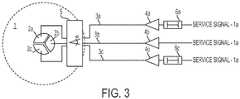
- FIG. 3schematically depicts an example of the multiple sector cell site system that includes three feed lines 3a-c and two phase shifters 6a, 6c.
- An example for a configuration where only a subset of the signal paths have a phase shifteris a three-sector configuration. It may be sufficient for the signal path for feed line 3a and the signal path for feed line 3c only to have a phase shifter, as shown in FIG.
- the signal path for feed line 3acan be adjusted to minimize the phase difference with the signal path for feed line 3b and the signal path for feed line 3c can be adjusted to minimize the phase difference with the signal path for feed line 3b such that the three signal paths can have a minimum phase difference with respect to neighboring signal paths.
- the cell site systemmay be installed as a single sector antenna system providing omnidirectional coverage, but the system can be switched to a multi-sector antenna system without requiring hardware or other physical changes.
- the systemcan be reconfigured between a single sector antenna system and a multi-sector antenna system according to a switching signal.
- the phase correlation measurement unit 5 and phase shifters 6a-cmay not be operated since signals in multi-sector operation are sufficiently de-correlated and phase adjustment is not used.
- the phase correlation measurement unit 5 and phase shifters 6a-ceven though not in operation, can be retained in place such that hardware changes are not needed.
- FIG. 4depicts an example of the cell site system in which three signals 8a-c for different sectors can be switched to three sectors 9a-c using switches 7a-c.
- the three signals 8a-ccan be radiated as a three-sector configuration into different sectors 9a-c such that the cell site system operates as a sectorized antenna system.
- the switches 7a-ccan switch from providing service signals 1a, single-sector signals, to providing signals 8a-c along feed lines 3a-c through the power amplifiers 4a-c in response to a switching signal received from a control device communicatively coupled to the switches 7a-c.
- the switching signalcan be communicated along the feed lines 3a-c to cause the phase correlation measurement unit 5 and phase shifters 6a-c to cease operation.
- the switching signalcan be generated in a control device in response to a software application executing in the control device according to a user input or automatically upon detection of a specified event.
- Phase correlation measurements according to various embodimentscan be performed in various ways and using different types of component configurations.
- FIG. 5schematically depicts an example of a phase correlation measurement unit 5 and phase shifters 6a, 6c in the cell site system according to one aspect.
- the signals from feed lines 3a-ccan be de-coupled from the feed lines 3a-c by RF decouplers 10a-c.
- the de-coupled signalscan be combined by combiners 11a-b.
- a de-coupled signal from feed line 3acan be combined with a de-coupled signal from feed line 3b and combined by combiner 11a.
- a de-coupled signal from feed line 3ccan be combined with the de-coupled signal from feed line 3b and combined by combiner 11b.
- the combined signalscan be rectified by rectified circuitry 12a-b to form rectified voltages.
- the direct current (DC) rectified voltagecan be coupled the feed lines 3a, 3c by DC on-couplers 14a-b and communicated toward phase shifters 6a, 6c on feed lines 3a, 3c.
- Bias-T circuitry 15a-bcan de-couple the rectified voltages from the feed lines 6a, 6c.
- the phase shift controllers 16a-bcan measure the rectified voltages and cause the phase shifters 6a, 6c to modify or retain the phase shift of the signals based on the measured voltages. For example, the phase shift controllers 16a-b can cause the phase shifters 6a, 6c to shift the phase of the signals until the measured voltages reaches a maximum as a maximum DC voltage can indicate a best phase-matching condition.
- a minimum DC voltagein contrast, may indicate a condition in which two signals are, or are approximately, 180° out of phase.
- signals from feed lines 3a and 3bare measured and phase shifted until a maximum DC voltage is detected. Then signals from feed lines 3b and 3c are measured and the signal for feed line 3c is phase shifted until a maximum DC voltage is detected. When signals from feed lines 3a and 3b are in phase and signals from feed lines 3b and 3c are in phase, signals from feed lines 3a and 3c are in phase.
- the rectified voltagescan be sent to the phase shift controllers 16a-b on the feed lines 3a, 3c to avoid additional wiring. But the rectified voltages can be sent to the phase shift controllers 16a-b through any communication channel.
- the signalsmay be test signals.
- the test signalsmay be continuous wave (CW) signals, which may exclude effects of group delay differences on measurement accuracy. Any type of test signal can be used.
- the test signalscan be modulated service signals transmitted during normal operation of the system.
- the modulated service signalscan be combined and filtered using a bandpass filter to approximate the combined signal as a CW signal in reducing effects of group delay differences for measurement accuracy.
- the service signalcan be approximated to a CW signal by the bandpass filter by the filter limiting the bandwidth of the signal such that group delay differences within the resulting bandwidth of the test signal can be close to zero, or otherwise negligible, which can be useful for measurement accuracy.
- the group delay differences among downlink signalsmay not be reduced.
- the phase correlation measurement unit 5may be a phase detection box that includes two boards: an RF board with high-quality factor material and a detection board that can have lower quality than the RF board.
- the phase correlation measurement unit 5 that includes the two boardscan result in the phase correlation measurement unit 5 being a small size and providing high isolation and low insertion loss at a low manufacturing cost.
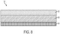
- FIG. 8depicts a side view of an example of a module 30 for the phase correlation measurement unit 5.
- the module 30includes an RF board 32, a detection board 34, and a metal plane 36 between the RF board 32 and the detection board 34 for isolating components on the RF board 32 from components on the detection board 34.
- FIG. 9schematically depicts a top view of the phase correlation measurement unit 5 and illustrates the boards on which components can be positioned.
- the componentsi.e., feed lines 3a-c, RF de-couplers 10a-c, and on-couplers 14a-b
- the components depicted with solid linescan be on the RF board 32 of FIG. 8 and components (i.e., combiners 11a-b, rectified circuitry 12a-b and 180° phase shifters 20a-b) depicted with dashed lines can be on the detection board 34 of FIG. 8 .
- Further metal planes 37 on the RF board 32can be positioned between the feed lines 3a and 3b and between the feed lines 3b and 3c, respectively, to increase isolation between the feed lines 3a-c.
- the phase correlation measurement unit 5can operate without requiring an external voltage supply.
- the phase correlation measurement unit 5can generate a DC voltage from the RF signals and can be powered from energy from the RF signals.
- the phase correlation measurement unit 5is powered by an external voltage by using at least one of the feed lines 3a-c for supplying the voltage.
- the phase correlation measurement unit 5can allow the phases of two or more RF signals to be automatically adjusted and correlated by relative measurements.
- absolute detected voltagecan be less important unless a minimum or maximum voltage is reached such that tuning expenses can be reduced (e.g., no calibrations for measurement setup) and accuracy can be increased. When a minimum or maximum voltage is reached, the absolute detected voltage may be less important. In other implementations, absolute phase differences are determined by the phase correlation measurement unit 5.
- FIG. 6schematically depicts an example of the phase correlation measurement unit 5 and phase shifters 6a, 6c in the cell site system according to another example.
- the phase correlation measurement unit 5includes fixed 180° phase shifters 20a-b ⁇ one positioned between de-coupler 10a and combiner 11a, and another positioned between de-coupler 10c and combiner 11b.
- Including fixed 180° phase shifters 20a-bcan result in minimum RF and voltage levels after phase differences are equalized (i.e., zero degrees ⁇ the intended operation mode for a single-section system), and may result in better selectivity of voltage over phase at minimum voltages. Intermodulation products can be minimized without additional filter elements.
- the DC voltagecan be a minimum when two de-coupled RF signals have a zero degree phase difference.
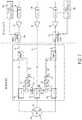
- FIG. 7schematically depicts an example of the phase correlation measurement unit 5 and phase shifters 6a, 6c in the cell site system according to another example in which filters 22a-b filter the combined signals prior to the combined signals being rectified for minimizing intermodulation products.
- the phase correlation measurement unit 5comprises filters 22a-b positioned between the combiner circuitry 11a-b and the rectifier circuitry 12a-b for reducing or eliminating intermodulation products generated by the combined signals.
- signal processing in the phase correlation measurement unit 5 or in another location in the systemcan combine the de-coupled signals and analyze the combined signals.
- the analysis of the combined signal itself or in combination with a controlled phase-shiftingcan produce information usable for setting the phase shifters 6a, 6c to a position for maximum phase correlation.
- Certain implementationscan provide a phase correlation measurement unit that is a phase detection box requiring no external voltage supply.
- the phase detection boxcan provide a DC voltage for evaluation, which can be easier to transport and process than RF signals, and continuous supervision during system operation.
- Phase adjustmentcan be implemented using a service signal such that no test signal or switching off the service signal is necessary. Intermodulation products can be minimized in some implementation using a 180° phase shift and additional filters can be used in some implementations. Low insertion loss, high isolation between RF paths without degradation of measurement accuracy, low cost, and small size can be achieved.
- Phase adjustment and alignmentcan be performed by relative measurements (e.g., a minimum or a maximum) such that expenditures for tuning can be reduced and accuracy can be increased.
Landscapes
- Engineering & Computer Science (AREA)
- Computer Networks & Wireless Communication (AREA)
- Signal Processing (AREA)
- Mobile Radio Communication Systems (AREA)
- Variable-Direction Aerials And Aerial Arrays (AREA)
Description
- This claims priority to
U.S. Provisional Application Serial No. 61/730,580 filed November 28, 2012 - The present disclosure relates generally to telecommunications and, more particularly (although not necessarily exclusively), to cell site systems that are reconfigurable between omnidirectional and sectorized operation.
- When a new cell site for wireless services (i.e., mobile communication) is established, the new cell site may be the first wireless coverage to be provided for the coverage area. When demand for more capacity increases at a later time and beyond the capabilities of the initial installation, the cell site infrastructure is often physically changed to provide the needed coverage capacity. Physical changes to the cell site infrastructure can include establishing smaller cells (i.e., more cell sites) or splitting a coverage cell into multiple sectors. Splitting a coverage cell into multiple sectors can involve less infrastructural changes than establishing multiple smaller cells, but it can still involve changing much of the initially installed hardware, e.g., antennas, feeding lines, feeding hardware, etc.
- When an initial cell site with an omnidirectional coverage pattern (i.e., single sector) is changed to a multi-sector site for capacity, multiple items in the installation may need to be modified at significant cost. For example, an omnidirectional antenna may need to be replaced by a multi-sector antenna (e.g., a three-sector antenna), a single coaxial feeder line may need to be upgraded to a multi-coaxial feeder line, and a full power feeding amplifier may need to be replaced with multiple feeding amplifiers (e.g., at one-third of full power each in the case of three sectors).
- Mechanisms and systems are needed to more efficiently transform a cell site for providing higher capacity coverage for an area.
WO 02/32028 A1 WO 02/32028 A1 WO 96/37970 A1 WO 96/37970 A1 US 2005/164744 A1 is directed at achieving higher data rates and higher throughout.US 2005/164744 A1 addresses this by providing an apparatus that comprises a software-controllable phased-array antenna with voltage tunable dielectric materials that enable concentration of RF energy from a transmitting wireless station into the direction of a receiving wireless station.DE 196 05 374 A1 is directed to increasing capacity, while reducing the amount of electromagnetic radiation and the transmission power of mobile phones and the BTS.DE 196 05 374 A1 addresses this by having variable horizontal directivity characteristics of frequency for the transmitting/receiving lobe.- A mobile can choose a carrier frequency based on optimum directional characteristics. The first and second horizontal directivities are associated with first and second carrier frequencies and bands as a voice channel).
- Document
US 2007/247363 A1 describes that measurements of frequency and/or phase are taken at the signal ports of an ISS device. These measurements are used to determine phase errors within the ISS device, and phase errors due to the antenna cables. On port, is selected as the reference port and then, based on these determined phase errors, offsetting phase errors are determined to correct the phase for the other ports with respect to the reference port. The signals at the antenna ports are then in phase when an omnidirectional antenna pattern is desired from the TCAS antenna array. For example, the frequency of the calibration signal can be fixed, or, two different fixed frequencies are used, or, the frequency is swept to achieve a predetermined measured phase difference. - The present invention is set out in the independent claims whereas preferred embodiments and further implementations are outlined in the dependent claims, description and figures.
FIG. 1 is a schematic of a multiple sector telecommunications system operable as an omnidirectional antenna system according to one example.FIG. 2 is a schematic of a multiple sector telecommunications system with a phase correlation measurement unit and phase shifters according to one example.FIG. 3 is a schematic of a multiple sector telecommunications system with a phase correlation measurement unit and phase shifters according to another example.FIG. 4 is a schematic of a multiple sector telecommunications system with a phase correlation measurement unit, phase shifters, and switches according to another example.FIG. 5 is a schematic of a phase correlation measurement unit and phase shifters according to one example.FIG. 6 is a schematic of a phase correlation measurement unit and phase shifters according to another example.FIG. 7 is a schematic of a phase correlation measurement unit and phase shifters according to another example.FIG. 8 is a side view of a module for a phase correlation measurement unit according to one example.FIG. 9 is a schematic top view of a phase correlation measurement unit with representations of the boards on which components can be positioned according to one example.- The invention is defined by the appended claims.
- Certain aspects and examples of the present disclosure are directed to establishing a cell site for initially operating as a single-sector cell site, but that is easily re-configurable to a multi-sector cell site at a later time without requiring replacement or upgrading of hardware. The cell site may also be re-configurable back to a single-sector cell site. Reconfiguration of the cell site can be controlled using commands from a software application rather that necessitating hardware changes.
- A cell site system according to some aspects can include an antenna sub-system with antennas for multiple sectors. Each antenna can be associated with a respective feed line that is coupled to a dedicated radio frequency (RF) source, which may be located remotely from the antenna sub-system. Examples of RF sources include remote radio heads, distributed antenna system units, and base transceiver stations. In a single-sector mode, the RF sources provide the same signal to the cell site and the antennas radiate the same signal for providing coverage in the coverage area by an omnidirectional coverage pattern. The signals can be radiated in phase to each other and kept at a low group delay spread in providing omnidirectional coverage. For example, a phase detection box can be positioned between the antenna subsystem and a remote unit that can include one or more RF sources. The phase detection box can be coupled to the remote unit over one or more feed lines. The phase detection box can output control signals to phase shifters for phase shifting downlink signals and for causing the antenna subsystem to operate as an omnidirectional antenna sub-system.
- These illustrative aspects and examples are given to introduce the reader to the general subject matter discussed here and are not intended to limit the scope of the disclosed concepts. The following sections describe various additional features and examples with reference to the drawings in which like numerals indicate like elements, but should not be used to limit the present disclosure.
FIG. 1 depicts an example of a multi-sector cell site that can provide a single-sector omnidirectional coverage pattern 1. The cell site includes an antenna subsystem withsectorized antennas 2a-c, one for each of three sectors. The sectorized antennas can radiate the same RF signal to provide the omnidirectional coverage pattern 1. The sectorized antennas can receive signals throughfeed lines 3a-c from RF sources represented bypower amplifiers 4a-c. The RF sources can support the same service signal and the signal can be radiated by thesectorized antennas 2a-c such that the behavior of the system is like that of a single-sector cell site. Although three sectorizedantennas 2a-c, threefeed lines 3a-c, and threepower amplifiers 4a-c (one power amplifier for each RF source) are shown by example, any number of each can be used.- The radiated signals can be phase matched to reduce or eliminate fading effects between the signals radiated by the sectorized
antennas 2a-c. Phase matching can include keeping phase differences between the radiated signals to a minimum. A phase difference of more than thirty degrees, for example, can influence (e.g., through deformation of the coverage-pattern) a homogenous coverage. For example, the RF sources orpower amplifiers 4a-c can have different phaseal behavior and thefeed lines 3a-c can have different phaseal behavior such that keeping a feeding service signal (e.g.,service signal 1a) phase matching may not be sufficient. Rather, the whole signal path may need to be analyzed and controlled. The phase correlation between the signals can be measured at theantennas 2a-c and a phase correlation can be adjusted according to the measurements to avoid fading effects at the pattern border of theantennas 2a-c. The adjustment of the phase correlation can be useful for initial system setup and to compensate phase drifts over time and based on temperature changes among other factors. FIG. 2 depicts an example of a multiple sector cell site system that can provide a single-sector omnidirectional coverage pattern 1. The system can include a phasecorrelation measurement unit 5 at theantennas 2a-c. The phasecorrelation measurement unit 5 can measure the phase difference between the signals on connections atfeed lines 3a-b and the phase difference between the signals onfeed lines 3b-c and the phase difference between the signals onfeed lines phase shifters 6a-c in the signal path to adjust the phase difference to a minimum.- The
phase shifters 6a-c can be at the inputs of thepower amplifiers 4a-c, or at any other point in the signal path to theantennas 2a-c. A phase shifter may be in every signal path or just in a subset of the used signal paths so that the neighboring sectors have an appropriate phase correlation.FIG. 3 schematically depicts an example of the multiple sector cell site system that includes threefeed lines 3a-c and twophase shifters feed line 3a and the signal path forfeed line 3c only to have a phase shifter, as shown inFIG. 3 , while the signal path forfeed line 3b is fixed. In this implementation, the signal path forfeed line 3a can be adjusted to minimize the phase difference with the signal path forfeed line 3b and the signal path forfeed line 3c can be adjusted to minimize the phase difference with the signal path forfeed line 3b such that the three signal paths can have a minimum phase difference with respect to neighboring signal paths. - The cell site system may be installed as a single sector antenna system providing omnidirectional coverage, but the system can be switched to a multi-sector antenna system without requiring hardware or other physical changes. The system can be reconfigured between a single sector antenna system and a multi-sector antenna system according to a switching signal. In multi-sector operation, the phase
correlation measurement unit 5 andphase shifters 6a-c may not be operated since signals in multi-sector operation are sufficiently de-correlated and phase adjustment is not used. The phasecorrelation measurement unit 5 andphase shifters 6a-c, even though not in operation, can be retained in place such that hardware changes are not needed. FIG. 4 depicts an example of the cell site system in which threesignals 8a-c for different sectors can be switched to threesectors 9a-c using switches 7a-c. The threesignals 8a-c can be radiated as a three-sector configuration intodifferent sectors 9a-c such that the cell site system operates as a sectorized antenna system. For example, theswitches 7a-c can switch from providingservice signals 1a, single-sector signals, to providingsignals 8a-c alongfeed lines 3a-c through thepower amplifiers 4a-c in response to a switching signal received from a control device communicatively coupled to theswitches 7a-c. In some aspects, the switching signal can be communicated along thefeed lines 3a-c to cause the phasecorrelation measurement unit 5 andphase shifters 6a-c to cease operation. The switching signal can be generated in a control device in response to a software application executing in the control device according to a user input or automatically upon detection of a specified event.- Phase correlation measurements according to various embodiments can be performed in various ways and using different types of component configurations.
FIG. 5 schematically depicts an example of a phasecorrelation measurement unit 5 andphase shifters feed lines 3a-c can be de-coupled from thefeed lines 3a-c by RF decouplers 10a-c. The de-coupled signals can be combined bycombiners 11a-b. For example, a de-coupled signal fromfeed line 3a can be combined with a de-coupled signal fromfeed line 3b and combined bycombiner 11a. A de-coupled signal fromfeed line 3c can be combined with the de-coupled signal fromfeed line 3b and combined bycombiner 11b. The combined signals can be rectified by rectifiedcircuitry 12a-b to form rectified voltages. The direct current (DC) rectified voltage can be coupled thefeed lines couplers 14a-b and communicated towardphase shifters feed lines T circuitry 15a-b can de-couple the rectified voltages from thefeed lines phase shift controllers 16a-b can measure the rectified voltages and cause thephase shifters phase shift controllers 16a-b can cause thephase shifters - In some implementations, signals from
feed lines feed lines feed line 3c is phase shifted until a maximum DC voltage is detected. When signals fromfeed lines feed lines feed lines - The rectified voltages can be sent to the
phase shift controllers 16a-b on thefeed lines phase shift controllers 16a-b through any communication channel. - The signals may be test signals. The test signals may be continuous wave (CW) signals, which may exclude effects of group delay differences on measurement accuracy. Any type of test signal can be used. In some aspects, the test signals can be modulated service signals transmitted during normal operation of the system. The modulated service signals can be combined and filtered using a bandpass filter to approximate the combined signal as a CW signal in reducing effects of group delay differences for measurement accuracy. The service signal can be approximated to a CW signal by the bandpass filter by the filter limiting the bandwidth of the signal such that group delay differences within the resulting bandwidth of the test signal can be close to zero, or otherwise negligible, which can be useful for measurement accuracy. The group delay differences among downlink signals may not be reduced.
- The phase
correlation measurement unit 5 may be a phase detection box that includes two boards: an RF board with high-quality factor material and a detection board that can have lower quality than the RF board. The phasecorrelation measurement unit 5 that includes the two boards can result in the phasecorrelation measurement unit 5 being a small size and providing high isolation and low insertion loss at a low manufacturing cost.FIG. 8 depicts a side view of an example of amodule 30 for the phasecorrelation measurement unit 5. Themodule 30 includes anRF board 32, adetection board 34, and ametal plane 36 between theRF board 32 and thedetection board 34 for isolating components on theRF board 32 from components on thedetection board 34.FIG. 9 schematically depicts a top view of the phasecorrelation measurement unit 5 and illustrates the boards on which components can be positioned. For example, the components (i.e.,feed lines 3a-c, RF de-couplers 10a-c, and on-couplers 14a-b) depicted with solid lines can be on theRF board 32 ofFIG. 8 and components (i.e.,combiners 11a-b, rectifiedcircuitry 12a-b and 180°phase shifters 20a-b) depicted with dashed lines can be on thedetection board 34 ofFIG. 8 .Further metal planes 37 on theRF board 32 can be positioned between thefeed lines feed lines feed lines 3a-c. - The phase
correlation measurement unit 5 can operate without requiring an external voltage supply. For example, the phasecorrelation measurement unit 5 can generate a DC voltage from the RF signals and can be powered from energy from the RF signals. In other embodiments, the phasecorrelation measurement unit 5 is powered by an external voltage by using at least one of thefeed lines 3a-c for supplying the voltage. - The phase
correlation measurement unit 5 can allow the phases of two or more RF signals to be automatically adjusted and correlated by relative measurements. In some implementations, absolute detected voltage can be less important unless a minimum or maximum voltage is reached such that tuning expenses can be reduced (e.g., no calibrations for measurement setup) and accuracy can be increased. When a minimum or maximum voltage is reached, the absolute detected voltage may be less important. In other implementations, absolute phase differences are determined by the phasecorrelation measurement unit 5. FIG. 6 schematically depicts an example of the phasecorrelation measurement unit 5 andphase shifters correlation measurement unit 5 includes fixed 180°phase shifters 20a-b ― one positioned betweende-coupler 10a andcombiner 11a, and another positioned between de-coupler 10c andcombiner 11b. Including fixed 180°phase shifters 20a-b can result in minimum RF and voltage levels after phase differences are equalized (i.e., zero degrees ― the intended operation mode for a single-section system), and may result in better selectivity of voltage over phase at minimum voltages. Intermodulation products can be minimized without additional filter elements. The DC voltage can be a minimum when two de-coupled RF signals have a zero degree phase difference.- The use of filters (e.g., bandpass, lowpass, highpass) can allow for the generation of intermodulation products to be minimized, for broadband or other types of systems, that operate with correlated signals and with uncorrelated signals (i.e., multi-sector).
FIG. 7 schematically depicts an example of the phasecorrelation measurement unit 5 andphase shifters correlation measurement unit 5 comprisesfilters 22a-b positioned between thecombiner circuitry 11a-b and therectifier circuitry 12a-b for reducing or eliminating intermodulation products generated by the combined signals. - In some implementations, signal processing in the phase
correlation measurement unit 5 or in another location in the system can combine the de-coupled signals and analyze the combined signals. The analysis of the combined signal itself or in combination with a controlled phase-shifting can produce information usable for setting thephase shifters - Certain implementations can provide a phase correlation measurement unit that is a phase detection box requiring no external voltage supply. The phase detection box can provide a DC voltage for evaluation, which can be easier to transport and process than RF signals, and continuous supervision during system operation. Phase adjustment can be implemented using a service signal such that no test signal or switching off the service signal is necessary. Intermodulation products can be minimized in some implementation using a 180° phase shift and additional filters can be used in some implementations. Low insertion loss, high isolation between RF paths without degradation of measurement accuracy, low cost, and small size can be achieved. Phase adjustment and alignment can be performed by relative measurements (e.g., a minimum or a maximum) such that expenditures for tuning can be reduced and accuracy can be increased.
- The foregoing description of the aspects, including illustrated examples, of the invention has been presented only for the purpose of illustration and description and is not intended to be exhaustive or to limit the invention to the precise forms disclosed. Numerous modifications, adaptations, and uses thereof will be apparent to those skilled in the art without departing from the scope of this invention.
Claims (15)
- A telecommunications system comprising:
a phase correlation measurement unit (5) positioned at a sectorized antenna sub-system (2a, 2b, 2c) of a cell site that is located remotely from a radio frequency, RF, source of the cell site, wherein the phase correlation measurement unit (5) is coupleable to the RF source of the cell site over at least two feed lines (3a, 3b, 3c), wherein the phase correlation measurement unit (5) is configured to determine a rectified voltage signal of a combined signal formed from at least two downlink signals and to output signals for controlling a phase shifter (4a, 4b, 4c) at the RF source of the cell site for phase shifting downlink signals based on a measured voltage of the rectified voltage signal such that the sectorized antenna sub-system (2a, 2b, 2c) of the cell site operates as an omnidirectional antenna sub-system using at least two phase-aligned downlink signals. - The telecommunications system of claim 1, wherein the phase correlation measurement unit (5) comprises:de-couplers (10a, 10b, 10c) for de-coupling downlink signals from the at least two feed lines (3a-3c);a combiner (11a, 11b) for combining at least two de-coupled downlink signals to provide the combined signal; andrectifier circuitry (12a, 12b) for producing the rectified voltage signal from the combined signal.
- The telecommunications system of claim 2, further comprising:
a phase shift controller (16a, 16b) at the RF source of the cell site for determining the measured voltage of the rectified voltage signal and controlling the phase shifter based on the measured voltage. - The telecommunications system of claim 3, wherein the phase correlation measurement unit (5) further comprises an on-coupler (14a, 14b) for coupling the rectified voltage signal to a feed line (3a, 3b, 3c).
- The telecommunications system of claim 3, wherein the phase shift controller (16a, 16b) is configured for causing the phase shifter (6a, 6c) to shift a phase of a downlink signal until a maximum measured voltage is determined.
- The telecommunications system of claim 2, wherein the phase correlation measurement unit (5) further comprises a 180° phase shifter (20a, 20b) positioned between a de-coupler (10a, 10b, 10c) and the combiner (11a, 11b), wherein the telecommunications system further comprises a phase shift controller (16a, 16b) at the RF source of the cell site for determining a measured voltage from the rectified voltage signal and causing the phase shifter (6a, 6c) to shift a phase of a downlink signal until a minimum measured voltage is determined.
- The telecommunications system of claim 1, wherein the telecommunications system is switchable between a single sector mode and a multiple sector mode based on a control signal, the sectorized antenna subsystem (2a, 2b, 2c) of the cell site being operable as the omnidirectional antenna sub-system in the single sector mode.
- A method, comprising:determining, by a phase correlation measurement unit, a rectified voltage signal of a combined signal formed from at least two downlink signals at a sectorized antenna sub-system of a cell site;controlling a phase shifter (6a, 6b, 6c) at a radio frequency, RF, source of the cell site for phase shifting downlink signals based on a measured voltage of the rectified voltage signal, wherein the RF source of the cell site is located remotely from the sectorized antenna sub-system of the cell site; andoperating the sectorized antenna sub-system of the cell site as an omnidirectional antenna sub-system using at least two phase-aligned downlink signals.
- The method of claim 8, further comprising:
inactivating the phase shifter (6a, 6b, 6c) when switching the sectorized antenna sub-system of the cell site to a multiple sector operation mode. - The method of claim 8, wherein multiple antennas (2a, 2b, 2c) of the sectorized antenna sub-system of the cell site radiate common information content into a coverage area (1) when operating in a omnidirectional operation mode, wherein the multiple antennas (2a, 2b, 2c) of the sectorized antenna sub-system of the cell site radiate different signals into different sectors (9a, 9b, 9c) of the coverage area when operating in a multiple sector operation mode.
- The method of claim 8, further comprising switching the sectorized antenna sub-system (2a, 2b, 2c) of the cell site from a omnidirectional operation mode to a multiple sector operation mode in response to a control signal without changing hardware components of the sectorized antenna sub-system of the cell site.
- The method of claim 8, further comprising:
phase shifting each of a first downlink signal and a second downlink signal such that the measured voltage is a maximum voltage or a minimum voltage, without phase shifting a third downlink signal. - The method of claim 8, wherein the at least two downlink signals are continuous wave signals at a center frequency of passband and that exclude effects of group delay differences for determining the measured voltage of the combined signal.
- The method of claim 8, wherein the at least two downlink signals are modulated service signals provided from RF sources of the cell cite during normal system operation, the method further comprising:
filtering the combined signal using a bandpass filter to approximate the combined signal as a continuous wave signal in reducing group delay differences among the at least two downlink signals. - The method of claim 8, wherein controlling the phase shifter at the RF source of the cell site for phase shifting downlink signals based on the measured voltage includes:phase aligning signals along a first feed line (3a) and a second feed line (3b); andphase aligning signals along the second feed line (3b) and a third feed line (3c) such that the signals along the first feed line (3a) and the third feed line (3c) are aligned.
Applications Claiming Priority (2)
| Application Number | Priority Date | Filing Date | Title |
|---|---|---|---|
| US201261730580P | 2012-11-28 | 2012-11-28 | |
| PCT/IB2013/060415WO2014083500A1 (en) | 2012-11-28 | 2013-11-26 | Reconfigurable single and multi-sector cell site system |
Publications (2)
| Publication Number | Publication Date |
|---|---|
| EP2926470A1 EP2926470A1 (en) | 2015-10-07 |
| EP2926470B1true EP2926470B1 (en) | 2021-09-29 |
Family
ID=50030355
Family Applications (1)
| Application Number | Title | Priority Date | Filing Date |
|---|---|---|---|
| EP13826606.9AActiveEP2926470B1 (en) | 2012-11-28 | 2013-11-26 | Reconfigurable single and multi-sector cell site system |
Country Status (3)
| Country | Link |
|---|---|
| US (2) | US9698882B2 (en) |
| EP (1) | EP2926470B1 (en) |
| WO (1) | WO2014083500A1 (en) |
Families Citing this family (143)
| Publication number | Priority date | Publication date | Assignee | Title |
|---|---|---|---|---|
| US9113347B2 (en) | 2012-12-05 | 2015-08-18 | At&T Intellectual Property I, Lp | Backhaul link for distributed antenna system |
| US10009065B2 (en) | 2012-12-05 | 2018-06-26 | At&T Intellectual Property I, L.P. | Backhaul link for distributed antenna system |
| US9999038B2 (en) | 2013-05-31 | 2018-06-12 | At&T Intellectual Property I, L.P. | Remote distributed antenna system |
| US9525524B2 (en) | 2013-05-31 | 2016-12-20 | At&T Intellectual Property I, L.P. | Remote distributed antenna system |
| US8897697B1 (en) | 2013-11-06 | 2014-11-25 | At&T Intellectual Property I, Lp | Millimeter-wave surface-wave communications |
| US9692101B2 (en) | 2014-08-26 | 2017-06-27 | At&T Intellectual Property I, L.P. | Guided wave couplers for coupling electromagnetic waves between a waveguide surface and a surface of a wire |
| US9768833B2 (en) | 2014-09-15 | 2017-09-19 | At&T Intellectual Property I, L.P. | Method and apparatus for sensing a condition in a transmission medium of electromagnetic waves |
| US10063280B2 (en) | 2014-09-17 | 2018-08-28 | At&T Intellectual Property I, L.P. | Monitoring and mitigating conditions in a communication network |
| US9615269B2 (en) | 2014-10-02 | 2017-04-04 | At&T Intellectual Property I, L.P. | Method and apparatus that provides fault tolerance in a communication network |
| US9685992B2 (en) | 2014-10-03 | 2017-06-20 | At&T Intellectual Property I, L.P. | Circuit panel network and methods thereof |
| US9503189B2 (en) | 2014-10-10 | 2016-11-22 | At&T Intellectual Property I, L.P. | Method and apparatus for arranging communication sessions in a communication system |
| US9973299B2 (en) | 2014-10-14 | 2018-05-15 | At&T Intellectual Property I, L.P. | Method and apparatus for adjusting a mode of communication in a communication network |
| US9762289B2 (en) | 2014-10-14 | 2017-09-12 | At&T Intellectual Property I, L.P. | Method and apparatus for transmitting or receiving signals in a transportation system |
| US9769020B2 (en) | 2014-10-21 | 2017-09-19 | At&T Intellectual Property I, L.P. | Method and apparatus for responding to events affecting communications in a communication network |
| US9577306B2 (en) | 2014-10-21 | 2017-02-21 | At&T Intellectual Property I, L.P. | Guided-wave transmission device and methods for use therewith |
| US9312919B1 (en) | 2014-10-21 | 2016-04-12 | At&T Intellectual Property I, Lp | Transmission device with impairment compensation and methods for use therewith |
| US9780834B2 (en) | 2014-10-21 | 2017-10-03 | At&T Intellectual Property I, L.P. | Method and apparatus for transmitting electromagnetic waves |
| US9627768B2 (en) | 2014-10-21 | 2017-04-18 | At&T Intellectual Property I, L.P. | Guided-wave transmission device with non-fundamental mode propagation and methods for use therewith |
| US9653770B2 (en) | 2014-10-21 | 2017-05-16 | At&T Intellectual Property I, L.P. | Guided wave coupler, coupling module and methods for use therewith |
| US10340573B2 (en) | 2016-10-26 | 2019-07-02 | At&T Intellectual Property I, L.P. | Launcher with cylindrical coupling device and methods for use therewith |
| US10009067B2 (en) | 2014-12-04 | 2018-06-26 | At&T Intellectual Property I, L.P. | Method and apparatus for configuring a communication interface |
| US9954287B2 (en) | 2014-11-20 | 2018-04-24 | At&T Intellectual Property I, L.P. | Apparatus for converting wireless signals and electromagnetic waves and methods thereof |
| US10243784B2 (en) | 2014-11-20 | 2019-03-26 | At&T Intellectual Property I, L.P. | System for generating topology information and methods thereof |
| US9997819B2 (en) | 2015-06-09 | 2018-06-12 | At&T Intellectual Property I, L.P. | Transmission medium and method for facilitating propagation of electromagnetic waves via a core |
| US9461706B1 (en) | 2015-07-31 | 2016-10-04 | At&T Intellectual Property I, Lp | Method and apparatus for exchanging communication signals |
| US9742462B2 (en) | 2014-12-04 | 2017-08-22 | At&T Intellectual Property I, L.P. | Transmission medium and communication interfaces and methods for use therewith |
| US9800327B2 (en) | 2014-11-20 | 2017-10-24 | At&T Intellectual Property I, L.P. | Apparatus for controlling operations of a communication device and methods thereof |
| US9544006B2 (en) | 2014-11-20 | 2017-01-10 | At&T Intellectual Property I, L.P. | Transmission device with mode division multiplexing and methods for use therewith |
| KR102153396B1 (en) | 2014-12-30 | 2020-09-08 | 주식회사 쏠리드 | Node unit capable of measuring delay and distributed antenna system including it |
| US10144036B2 (en) | 2015-01-30 | 2018-12-04 | At&T Intellectual Property I, L.P. | Method and apparatus for mitigating interference affecting a propagation of electromagnetic waves guided by a transmission medium |
| US9876570B2 (en) | 2015-02-20 | 2018-01-23 | At&T Intellectual Property I, Lp | Guided-wave transmission device with non-fundamental mode propagation and methods for use therewith |
| US9749013B2 (en) | 2015-03-17 | 2017-08-29 | At&T Intellectual Property I, L.P. | Method and apparatus for reducing attenuation of electromagnetic waves guided by a transmission medium |
| US10224981B2 (en) | 2015-04-24 | 2019-03-05 | At&T Intellectual Property I, Lp | Passive electrical coupling device and methods for use therewith |
| US9705561B2 (en) | 2015-04-24 | 2017-07-11 | At&T Intellectual Property I, L.P. | Directional coupling device and methods for use therewith |
| US9793954B2 (en) | 2015-04-28 | 2017-10-17 | At&T Intellectual Property I, L.P. | Magnetic coupling device and methods for use therewith |
| US9948354B2 (en) | 2015-04-28 | 2018-04-17 | At&T Intellectual Property I, L.P. | Magnetic coupling device with reflective plate and methods for use therewith |
| US9490869B1 (en) | 2015-05-14 | 2016-11-08 | At&T Intellectual Property I, L.P. | Transmission medium having multiple cores and methods for use therewith |
| US9748626B2 (en) | 2015-05-14 | 2017-08-29 | At&T Intellectual Property I, L.P. | Plurality of cables having different cross-sectional shapes which are bundled together to form a transmission medium |
| US9871282B2 (en) | 2015-05-14 | 2018-01-16 | At&T Intellectual Property I, L.P. | At least one transmission medium having a dielectric surface that is covered at least in part by a second dielectric |
| US10650940B2 (en) | 2015-05-15 | 2020-05-12 | At&T Intellectual Property I, L.P. | Transmission medium having a conductive material and methods for use therewith |
| US9917341B2 (en) | 2015-05-27 | 2018-03-13 | At&T Intellectual Property I, L.P. | Apparatus and method for launching electromagnetic waves and for modifying radial dimensions of the propagating electromagnetic waves |
| US10103801B2 (en) | 2015-06-03 | 2018-10-16 | At&T Intellectual Property I, L.P. | Host node device and methods for use therewith |
| US9912381B2 (en) | 2015-06-03 | 2018-03-06 | At&T Intellectual Property I, Lp | Network termination and methods for use therewith |
| US10812174B2 (en) | 2015-06-03 | 2020-10-20 | At&T Intellectual Property I, L.P. | Client node device and methods for use therewith |
| US9866309B2 (en) | 2015-06-03 | 2018-01-09 | At&T Intellectual Property I, Lp | Host node device and methods for use therewith |
| US9913139B2 (en) | 2015-06-09 | 2018-03-06 | At&T Intellectual Property I, L.P. | Signal fingerprinting for authentication of communicating devices |
| US9608692B2 (en) | 2015-06-11 | 2017-03-28 | At&T Intellectual Property I, L.P. | Repeater and methods for use therewith |
| US9820146B2 (en) | 2015-06-12 | 2017-11-14 | At&T Intellectual Property I, L.P. | Method and apparatus for authentication and identity management of communicating devices |
| US9667317B2 (en) | 2015-06-15 | 2017-05-30 | At&T Intellectual Property I, L.P. | Method and apparatus for providing security using network traffic adjustments |
| US9865911B2 (en) | 2015-06-25 | 2018-01-09 | At&T Intellectual Property I, L.P. | Waveguide system for slot radiating first electromagnetic waves that are combined into a non-fundamental wave mode second electromagnetic wave on a transmission medium |
| US9640850B2 (en) | 2015-06-25 | 2017-05-02 | At&T Intellectual Property I, L.P. | Methods and apparatus for inducing a non-fundamental wave mode on a transmission medium |
| US9509415B1 (en) | 2015-06-25 | 2016-11-29 | At&T Intellectual Property I, L.P. | Methods and apparatus for inducing a fundamental wave mode on a transmission medium |
| US9853342B2 (en) | 2015-07-14 | 2017-12-26 | At&T Intellectual Property I, L.P. | Dielectric transmission medium connector and methods for use therewith |
| US10148016B2 (en) | 2015-07-14 | 2018-12-04 | At&T Intellectual Property I, L.P. | Apparatus and methods for communicating utilizing an antenna array |
| US9882257B2 (en) | 2015-07-14 | 2018-01-30 | At&T Intellectual Property I, L.P. | Method and apparatus for launching a wave mode that mitigates interference |
| US10205655B2 (en) | 2015-07-14 | 2019-02-12 | At&T Intellectual Property I, L.P. | Apparatus and methods for communicating utilizing an antenna array and multiple communication paths |
| US10033108B2 (en) | 2015-07-14 | 2018-07-24 | At&T Intellectual Property I, L.P. | Apparatus and methods for generating an electromagnetic wave having a wave mode that mitigates interference |
| US9628116B2 (en) | 2015-07-14 | 2017-04-18 | At&T Intellectual Property I, L.P. | Apparatus and methods for transmitting wireless signals |
| US9722318B2 (en) | 2015-07-14 | 2017-08-01 | At&T Intellectual Property I, L.P. | Method and apparatus for coupling an antenna to a device |
| US10044409B2 (en) | 2015-07-14 | 2018-08-07 | At&T Intellectual Property I, L.P. | Transmission medium and methods for use therewith |
| US10341142B2 (en) | 2015-07-14 | 2019-07-02 | At&T Intellectual Property I, L.P. | Apparatus and methods for generating non-interfering electromagnetic waves on an uninsulated conductor |
| US10170840B2 (en) | 2015-07-14 | 2019-01-01 | At&T Intellectual Property I, L.P. | Apparatus and methods for sending or receiving electromagnetic signals |
| US10320586B2 (en) | 2015-07-14 | 2019-06-11 | At&T Intellectual Property I, L.P. | Apparatus and methods for generating non-interfering electromagnetic waves on an insulated transmission medium |
| US10033107B2 (en) | 2015-07-14 | 2018-07-24 | At&T Intellectual Property I, L.P. | Method and apparatus for coupling an antenna to a device |
| US9847566B2 (en) | 2015-07-14 | 2017-12-19 | At&T Intellectual Property I, L.P. | Method and apparatus for adjusting a field of a signal to mitigate interference |
| US9608740B2 (en) | 2015-07-15 | 2017-03-28 | At&T Intellectual Property I, L.P. | Method and apparatus for launching a wave mode that mitigates interference |
| US9793951B2 (en) | 2015-07-15 | 2017-10-17 | At&T Intellectual Property I, L.P. | Method and apparatus for launching a wave mode that mitigates interference |
| US10090606B2 (en) | 2015-07-15 | 2018-10-02 | At&T Intellectual Property I, L.P. | Antenna system with dielectric array and methods for use therewith |
| US9871283B2 (en) | 2015-07-23 | 2018-01-16 | At&T Intellectual Property I, Lp | Transmission medium having a dielectric core comprised of plural members connected by a ball and socket configuration |
| US9749053B2 (en) | 2015-07-23 | 2017-08-29 | At&T Intellectual Property I, L.P. | Node device, repeater and methods for use therewith |
| US9948333B2 (en) | 2015-07-23 | 2018-04-17 | At&T Intellectual Property I, L.P. | Method and apparatus for wireless communications to mitigate interference |
| US9912027B2 (en) | 2015-07-23 | 2018-03-06 | At&T Intellectual Property I, L.P. | Method and apparatus for exchanging communication signals |
| US9967173B2 (en) | 2015-07-31 | 2018-05-08 | At&T Intellectual Property I, L.P. | Method and apparatus for authentication and identity management of communicating devices |
| US9735833B2 (en) | 2015-07-31 | 2017-08-15 | At&T Intellectual Property I, L.P. | Method and apparatus for communications management in a neighborhood network |
| US9904535B2 (en) | 2015-09-14 | 2018-02-27 | At&T Intellectual Property I, L.P. | Method and apparatus for distributing software |
| US10009063B2 (en) | 2015-09-16 | 2018-06-26 | At&T Intellectual Property I, L.P. | Method and apparatus for use with a radio distributed antenna system having an out-of-band reference signal |
| US10079661B2 (en) | 2015-09-16 | 2018-09-18 | At&T Intellectual Property I, L.P. | Method and apparatus for use with a radio distributed antenna system having a clock reference |
| US10136434B2 (en) | 2015-09-16 | 2018-11-20 | At&T Intellectual Property I, L.P. | Method and apparatus for use with a radio distributed antenna system having an ultra-wideband control channel |
| US9769128B2 (en) | 2015-09-28 | 2017-09-19 | At&T Intellectual Property I, L.P. | Method and apparatus for encryption of communications over a network |
| US9729197B2 (en) | 2015-10-01 | 2017-08-08 | At&T Intellectual Property I, L.P. | Method and apparatus for communicating network management traffic over a network |
| US9876264B2 (en) | 2015-10-02 | 2018-01-23 | At&T Intellectual Property I, Lp | Communication system, guided wave switch and methods for use therewith |
| US10355367B2 (en) | 2015-10-16 | 2019-07-16 | At&T Intellectual Property I, L.P. | Antenna structure for exchanging wireless signals |
| US10665942B2 (en) | 2015-10-16 | 2020-05-26 | At&T Intellectual Property I, L.P. | Method and apparatus for adjusting wireless communications |
| US9912419B1 (en) | 2016-08-24 | 2018-03-06 | At&T Intellectual Property I, L.P. | Method and apparatus for managing a fault in a distributed antenna system |
| US9860075B1 (en) | 2016-08-26 | 2018-01-02 | At&T Intellectual Property I, L.P. | Method and communication node for broadband distribution |
| US10291311B2 (en) | 2016-09-09 | 2019-05-14 | At&T Intellectual Property I, L.P. | Method and apparatus for mitigating a fault in a distributed antenna system |
| US11032819B2 (en) | 2016-09-15 | 2021-06-08 | At&T Intellectual Property I, L.P. | Method and apparatus for use with a radio distributed antenna system having a control channel reference signal |
| US10340600B2 (en) | 2016-10-18 | 2019-07-02 | At&T Intellectual Property I, L.P. | Apparatus and methods for launching guided waves via plural waveguide systems |
| US10135147B2 (en) | 2016-10-18 | 2018-11-20 | At&T Intellectual Property I, L.P. | Apparatus and methods for launching guided waves via an antenna |
| US10374316B2 (en) | 2016-10-21 | 2019-08-06 | At&T Intellectual Property I, L.P. | System and dielectric antenna with non-uniform dielectric |
| US9876605B1 (en) | 2016-10-21 | 2018-01-23 | At&T Intellectual Property I, L.P. | Launcher and coupling system to support desired guided wave mode |
| US9991580B2 (en) | 2016-10-21 | 2018-06-05 | At&T Intellectual Property I, L.P. | Launcher and coupling system for guided wave mode cancellation |
| US10811767B2 (en) | 2016-10-21 | 2020-10-20 | At&T Intellectual Property I, L.P. | System and dielectric antenna with convex dielectric radome |
| US10312567B2 (en) | 2016-10-26 | 2019-06-04 | At&T Intellectual Property I, L.P. | Launcher with planar strip antenna and methods for use therewith |
| US10225025B2 (en) | 2016-11-03 | 2019-03-05 | At&T Intellectual Property I, L.P. | Method and apparatus for detecting a fault in a communication system |
| US10291334B2 (en) | 2016-11-03 | 2019-05-14 | At&T Intellectual Property I, L.P. | System for detecting a fault in a communication system |
| US10224634B2 (en) | 2016-11-03 | 2019-03-05 | At&T Intellectual Property I, L.P. | Methods and apparatus for adjusting an operational characteristic of an antenna |
| US10498044B2 (en) | 2016-11-03 | 2019-12-03 | At&T Intellectual Property I, L.P. | Apparatus for configuring a surface of an antenna |
| US10340603B2 (en) | 2016-11-23 | 2019-07-02 | At&T Intellectual Property I, L.P. | Antenna system having shielded structural configurations for assembly |
| US10535928B2 (en) | 2016-11-23 | 2020-01-14 | At&T Intellectual Property I, L.P. | Antenna system and methods for use therewith |
| US10340601B2 (en) | 2016-11-23 | 2019-07-02 | At&T Intellectual Property I, L.P. | Multi-antenna system and methods for use therewith |
| US10178445B2 (en) | 2016-11-23 | 2019-01-08 | At&T Intellectual Property I, L.P. | Methods, devices, and systems for load balancing between a plurality of waveguides |
| US10305190B2 (en) | 2016-12-01 | 2019-05-28 | At&T Intellectual Property I, L.P. | Reflecting dielectric antenna system and methods for use therewith |
| US10361489B2 (en) | 2016-12-01 | 2019-07-23 | At&T Intellectual Property I, L.P. | Dielectric dish antenna system and methods for use therewith |
| US10439675B2 (en) | 2016-12-06 | 2019-10-08 | At&T Intellectual Property I, L.P. | Method and apparatus for repeating guided wave communication signals |
| US10727599B2 (en) | 2016-12-06 | 2020-07-28 | At&T Intellectual Property I, L.P. | Launcher with slot antenna and methods for use therewith |
| US10135145B2 (en) | 2016-12-06 | 2018-11-20 | At&T Intellectual Property I, L.P. | Apparatus and methods for generating an electromagnetic wave along a transmission medium |
| US10637149B2 (en) | 2016-12-06 | 2020-04-28 | At&T Intellectual Property I, L.P. | Injection molded dielectric antenna and methods for use therewith |
| US10755542B2 (en) | 2016-12-06 | 2020-08-25 | At&T Intellectual Property I, L.P. | Method and apparatus for surveillance via guided wave communication |
| US10819035B2 (en) | 2016-12-06 | 2020-10-27 | At&T Intellectual Property I, L.P. | Launcher with helical antenna and methods for use therewith |
| US10382976B2 (en) | 2016-12-06 | 2019-08-13 | At&T Intellectual Property I, L.P. | Method and apparatus for managing wireless communications based on communication paths and network device positions |
| US10694379B2 (en) | 2016-12-06 | 2020-06-23 | At&T Intellectual Property I, L.P. | Waveguide system with device-based authentication and methods for use therewith |
| US9927517B1 (en) | 2016-12-06 | 2018-03-27 | At&T Intellectual Property I, L.P. | Apparatus and methods for sensing rainfall |
| US10326494B2 (en) | 2016-12-06 | 2019-06-18 | At&T Intellectual Property I, L.P. | Apparatus for measurement de-embedding and methods for use therewith |
| US10020844B2 (en) | 2016-12-06 | 2018-07-10 | T&T Intellectual Property I, L.P. | Method and apparatus for broadcast communication via guided waves |
| US9893795B1 (en) | 2016-12-07 | 2018-02-13 | At&T Intellectual Property I, Lp | Method and repeater for broadband distribution |
| US10139820B2 (en) | 2016-12-07 | 2018-11-27 | At&T Intellectual Property I, L.P. | Method and apparatus for deploying equipment of a communication system |
| US10389029B2 (en) | 2016-12-07 | 2019-08-20 | At&T Intellectual Property I, L.P. | Multi-feed dielectric antenna system with core selection and methods for use therewith |
| US10027397B2 (en) | 2016-12-07 | 2018-07-17 | At&T Intellectual Property I, L.P. | Distributed antenna system and methods for use therewith |
| US10243270B2 (en) | 2016-12-07 | 2019-03-26 | At&T Intellectual Property I, L.P. | Beam adaptive multi-feed dielectric antenna system and methods for use therewith |
| US10547348B2 (en) | 2016-12-07 | 2020-01-28 | At&T Intellectual Property I, L.P. | Method and apparatus for switching transmission mediums in a communication system |
| US10446936B2 (en) | 2016-12-07 | 2019-10-15 | At&T Intellectual Property I, L.P. | Multi-feed dielectric antenna system and methods for use therewith |
| US10168695B2 (en) | 2016-12-07 | 2019-01-01 | At&T Intellectual Property I, L.P. | Method and apparatus for controlling an unmanned aircraft |
| US10359749B2 (en) | 2016-12-07 | 2019-07-23 | At&T Intellectual Property I, L.P. | Method and apparatus for utilities management via guided wave communication |
| US10069535B2 (en) | 2016-12-08 | 2018-09-04 | At&T Intellectual Property I, L.P. | Apparatus and methods for launching electromagnetic waves having a certain electric field structure |
| US10530505B2 (en) | 2016-12-08 | 2020-01-07 | At&T Intellectual Property I, L.P. | Apparatus and methods for launching electromagnetic waves along a transmission medium |
| US9911020B1 (en) | 2016-12-08 | 2018-03-06 | At&T Intellectual Property I, L.P. | Method and apparatus for tracking via a radio frequency identification device |
| US9998870B1 (en) | 2016-12-08 | 2018-06-12 | At&T Intellectual Property I, L.P. | Method and apparatus for proximity sensing |
| US10389037B2 (en) | 2016-12-08 | 2019-08-20 | At&T Intellectual Property I, L.P. | Apparatus and methods for selecting sections of an antenna array and use therewith |
| US10777873B2 (en) | 2016-12-08 | 2020-09-15 | At&T Intellectual Property I, L.P. | Method and apparatus for mounting network devices |
| US10916969B2 (en) | 2016-12-08 | 2021-02-09 | At&T Intellectual Property I, L.P. | Method and apparatus for providing power using an inductive coupling |
| US10326689B2 (en) | 2016-12-08 | 2019-06-18 | At&T Intellectual Property I, L.P. | Method and system for providing alternative communication paths |
| US10938108B2 (en) | 2016-12-08 | 2021-03-02 | At&T Intellectual Property I, L.P. | Frequency selective multi-feed dielectric antenna system and methods for use therewith |
| US10601494B2 (en) | 2016-12-08 | 2020-03-24 | At&T Intellectual Property I, L.P. | Dual-band communication device and method for use therewith |
| US10411356B2 (en) | 2016-12-08 | 2019-09-10 | At&T Intellectual Property I, L.P. | Apparatus and methods for selectively targeting communication devices with an antenna array |
| US10103422B2 (en) | 2016-12-08 | 2018-10-16 | At&T Intellectual Property I, L.P. | Method and apparatus for mounting network devices |
| US10264586B2 (en) | 2016-12-09 | 2019-04-16 | At&T Mobility Ii Llc | Cloud-based packet controller and methods for use therewith |
| US10340983B2 (en) | 2016-12-09 | 2019-07-02 | At&T Intellectual Property I, L.P. | Method and apparatus for surveying remote sites via guided wave communications |
| US9838896B1 (en) | 2016-12-09 | 2017-12-05 | At&T Intellectual Property I, L.P. | Method and apparatus for assessing network coverage |
| US9973940B1 (en) | 2017-02-27 | 2018-05-15 | At&T Intellectual Property I, L.P. | Apparatus and methods for dynamic impedance matching of a guided wave launcher |
| US10298293B2 (en) | 2017-03-13 | 2019-05-21 | At&T Intellectual Property I, L.P. | Apparatus of communication utilizing wireless network devices |
| KR102429432B1 (en)* | 2018-03-07 | 2022-08-04 | 삼성전자주식회사 | Base station and method thereof for communicating using a plurality of antennas |
| KR20220005822A (en) | 2020-07-07 | 2022-01-14 | 삼성전자주식회사 | Dual polarized antenna and electronic device including the same |
Family Cites Families (33)
| Publication number | Priority date | Publication date | Assignee | Title |
|---|---|---|---|---|
| US4369520A (en) | 1979-03-22 | 1983-01-18 | Motorola, Inc. | Instantaneously acquiring sector antenna combining system |
| US4491845A (en)* | 1982-11-23 | 1985-01-01 | The United States Of America As Represented By The Secretary Of The Air Force | Wide angle phased array dome lens antenna with a reflection/transmission switch |
| US5493306A (en) | 1987-08-28 | 1996-02-20 | Eaton Corporation | Phased array antenna system to produce wide-open coverage of a wide angular section with high directive gain and moderate capability to resolve multiple signals |
| US5303394A (en)* | 1991-08-09 | 1994-04-12 | Rockwell International | Feedback stabilized Q multiplier filter circuit |
| FI944346L (en) | 1994-09-19 | 1996-03-20 | Nokia Telecommunications Oy | Base station |
| DE19605374A1 (en) | 1995-02-22 | 1996-08-29 | Cryoelectra Ges Fuer Kryoelekt | Radio transmitter method for GSM mobile radio telephone |
| FI98171C (en) | 1995-05-24 | 1997-04-25 | Nokia Telecommunications Oy | Procedure for transmitting pilot channels and cellular radio systems |
| US6456610B1 (en)* | 1995-11-07 | 2002-09-24 | Lucent Technologies Inc. | TDM/TDMA wireless telecommunication system with electronic scanning antenna |
| US6198435B1 (en)* | 1997-01-27 | 2001-03-06 | Metawave Communications Corporation | System and method for improved trunking efficiency through sector overlap |
| US6154661A (en)* | 1997-12-10 | 2000-11-28 | Arraycomm, Inc. | Transmitting on the downlink using one or more weight vectors determined to achieve a desired radiation pattern |
| US6091970A (en) | 1997-12-24 | 2000-07-18 | Nortel Networks Corporation | Pseudo-omnidirectional base station arrangement |
| US6233466B1 (en)* | 1998-12-14 | 2001-05-15 | Metawave Communications Corporation | Downlink beamforming using beam sweeping and subscriber feedback |
| US6864853B2 (en) | 1999-10-15 | 2005-03-08 | Andrew Corporation | Combination directional/omnidirectional antenna |
| EP1111812A1 (en) | 1999-12-20 | 2001-06-27 | Nortel Matra Cellular | Omni transmit and sectored receive cellular telecommunications network and method of operating the same |
| US6704577B1 (en)* | 2000-03-31 | 2004-03-09 | Qualcomm, Incorporated | Efficient searching by a remote unit in a slotted mode communication system |
| US6504517B1 (en)* | 2000-09-12 | 2003-01-07 | Lucent Technologies Inc. | Variable sectorization tower top applique for base stations |
| WO2002032028A1 (en) | 2000-10-13 | 2002-04-18 | Repeater Technologies | Microcell delay-sectorization system for cdma base transmitter site |
| GB0027759D0 (en)* | 2000-11-14 | 2000-12-27 | Univ Leicester | X-ray generator |
| FI20011217A7 (en) | 2001-06-08 | 2002-12-09 | Nokia Corp | Reception method, radio system and receiver |
| RU2208808C2 (en) | 2001-10-04 | 2003-07-20 | Войсковая часть 25714 | Omnidirectional radio direction finder |
| US7386305B2 (en)* | 2002-09-20 | 2008-06-10 | Qualcomm Incorporated | System and method for selectively forming and rotating a transmission beam |
| KR100584328B1 (en)* | 2003-10-07 | 2006-05-26 | 삼성전자주식회사 | Mobile terminal circuit combined with radio frequency identification tag and wireless identification method in mobile terminal |
| US6989697B2 (en)* | 2004-01-15 | 2006-01-24 | Organicid, Inc. | Non-quasistatic phase lock loop frequency divider circuit |
| US20050164744A1 (en)* | 2004-01-28 | 2005-07-28 | Du Toit Nicolaas D. | Apparatus and method operable in a wireless local area network incorporating tunable dielectric capacitors embodied within an inteligent adaptive antenna |
| GB0426354D0 (en) | 2004-12-01 | 2005-01-05 | Quintel Technology Ltd | Sectorisation of cellular radio |
| EP1964211A4 (en) | 2005-12-12 | 2011-04-27 | Wi Lan Inc | Self-installable switchable antenna |
| KR100904681B1 (en) | 2005-12-15 | 2009-06-25 | 한국전자통신연구원 | Method and apparatus for transmitter locating using a single receiver |
| US7482976B2 (en)* | 2006-04-10 | 2009-01-27 | Aviation Communication & Surveillance Systems | Antenna calibration method and apparatus |
| US7697959B2 (en) | 2006-10-10 | 2010-04-13 | Intel Corporation | Adaptive multiple-antenna systems with omni-directional and sector-directional antenna modes |
| JP4823943B2 (en)* | 2007-03-06 | 2011-11-24 | 均 北吉 | Wireless tag, wireless tag reader, pulse encoding key detection circuit, and wireless tag system using them |
| US8116819B2 (en) | 2008-12-31 | 2012-02-14 | Intel Corporation | Arrangements for beam refinement in a wireless network |
| US8243637B2 (en) | 2009-05-29 | 2012-08-14 | Alcatel Lucent | Method and apparatus for mobile broadcast and multicast using randomized transmit signal phases in a single frequency network |
| US9490944B2 (en)* | 2012-10-12 | 2016-11-08 | Innoventure L.P. | Phase sector based RF signal acquisition |
- 2013
- 2013-11-26EPEP13826606.9Apatent/EP2926470B1/enactiveActive
- 2013-11-26USUS14/439,938patent/US9698882B2/ennot_activeExpired - Fee Related
- 2013-11-26WOPCT/IB2013/060415patent/WO2014083500A1/enactiveApplication Filing
- 2017
- 2017-06-30USUS15/638,907patent/US10200881B2/enactiveActive
Also Published As
| Publication number | Publication date |
|---|---|
| US9698882B2 (en) | 2017-07-04 |
| US20170303142A1 (en) | 2017-10-19 |
| US20150304005A1 (en) | 2015-10-22 |
| WO2014083500A1 (en) | 2014-06-05 |
| EP2926470A1 (en) | 2015-10-07 |
| US10200881B2 (en) | 2019-02-05 |
Similar Documents
| Publication | Publication Date | Title |
|---|---|---|
| EP2926470B1 (en) | Reconfigurable single and multi-sector cell site system | |
| US9030363B2 (en) | Method and apparatus for tilting beams in a mobile communications network | |
| CN111095003B (en) | Method for calibrating a millimeter wave antenna array | |
| US8463222B2 (en) | Multiple-input-multiple-output antenna device | |
| US8106826B2 (en) | Antenna arrangement | |
| EP2816664B1 (en) | Antenna system | |
| JP6174574B2 (en) | Antenna control | |
| US10886630B2 (en) | Antenna module and communication device | |
| US11362440B2 (en) | Antenna device, wireless transmitter, wireless receiver, and wireless communication system | |
| CN104901025B (en) | A kind of implementation method and device, Anneta module of Anneta module | |
| US20210378091A1 (en) | Calibration circuit board and antenna apparatus including the same | |
| US20190326662A1 (en) | Base station antennas that utilize amplitude-weighted and phase-weighted linear superposition to support high effective isotropic radiated power (eirp) with high boresight coverage | |
| US20170373371A1 (en) | Method and System for the Automated Alignment of Antennas | |
| CN106716714A (en) | Stadium antenna | |
| CN114552214B (en) | Antenna System | |
| WO2021003030A1 (en) | Antenna feed networks and related antennas and methods | |
| WO2017051352A1 (en) | Remote antenna unit (rau) with multiple antenna assembly in a distributed antenna system (das) | |
| CN114696086B (en) | Feeding network, base station antenna and base station equipment | |
| CN102509892A (en) | Electrically adjustable antenna system and method | |
| US20190319655A1 (en) | Antenna apparatus and wireless apparatus | |
| US9548852B2 (en) | Antenna cross connect scheme for LTE | |
| US20190109630A1 (en) | Heterogeneously equipped multi antenna system and method of operating such system | |
| EP2819241B1 (en) | Adaptive antenna and a method of controlling an adaptive antenna beam | |
| JPWO2019221130A1 (en) | Array communication device and its control method |
Legal Events
| Date | Code | Title | Description |
|---|---|---|---|
| PUAI | Public reference made under article 153(3) epc to a published international application that has entered the european phase | Free format text:ORIGINAL CODE: 0009012 | |
| 17P | Request for examination filed | Effective date:20150624 | |
| AK | Designated contracting states | Kind code of ref document:A1 Designated state(s):AL AT BE BG CH CY CZ DE DK EE ES FI FR GB GR HR HU IE IS IT LI LT LU LV MC MK MT NL NO PL PT RO RS SE SI SK SM TR | |
| AX | Request for extension of the european patent | Extension state:BA ME | |
| DAX | Request for extension of the european patent (deleted) | ||
| 17Q | First examination report despatched | Effective date:20160602 | |
| STAA | Information on the status of an ep patent application or granted ep patent | Free format text:STATUS: EXAMINATION IS IN PROGRESS | |
| GRAP | Despatch of communication of intention to grant a patent | Free format text:ORIGINAL CODE: EPIDOSNIGR1 | |
| STAA | Information on the status of an ep patent application or granted ep patent | Free format text:STATUS: GRANT OF PATENT IS INTENDED | |
| INTG | Intention to grant announced | Effective date:20200219 | |
| GRAJ | Information related to disapproval of communication of intention to grant by the applicant or resumption of examination proceedings by the epo deleted | Free format text:ORIGINAL CODE: EPIDOSDIGR1 | |
| STAA | Information on the status of an ep patent application or granted ep patent | Free format text:STATUS: EXAMINATION IS IN PROGRESS | |
| INTC | Intention to grant announced (deleted) | ||
| GRAP | Despatch of communication of intention to grant a patent | Free format text:ORIGINAL CODE: EPIDOSNIGR1 | |
| STAA | Information on the status of an ep patent application or granted ep patent | Free format text:STATUS: GRANT OF PATENT IS INTENDED | |
| INTG | Intention to grant announced | Effective date:20210519 | |
| GRAS | Grant fee paid | Free format text:ORIGINAL CODE: EPIDOSNIGR3 | |
| GRAA | (expected) grant | Free format text:ORIGINAL CODE: 0009210 | |
| STAA | Information on the status of an ep patent application or granted ep patent | Free format text:STATUS: THE PATENT HAS BEEN GRANTED | |
| AK | Designated contracting states | Kind code of ref document:B1 Designated state(s):AL AT BE BG CH CY CZ DE DK EE ES FI FR GB GR HR HU IE IS IT LI LT LU LV MC MK MT NL NO PL PT RO RS SE SI SK SM TR | |
| REG | Reference to a national code | Ref country code:GB Ref legal event code:FG4D | |
| REG | Reference to a national code | Ref country code:DE Ref legal event code:R096 Ref document number:602013079475 Country of ref document:DE | |
| REG | Reference to a national code | Ref country code:CH Ref legal event code:EP Ref country code:AT Ref legal event code:REF Ref document number:1435130 Country of ref document:AT Kind code of ref document:T Effective date:20211015 | |
| REG | Reference to a national code | Ref country code:IE Ref legal event code:FG4D | |
| REG | Reference to a national code | Ref country code:LT Ref legal event code:MG9D | |
| PG25 | Lapsed in a contracting state [announced via postgrant information from national office to epo] | Ref country code:RS Free format text:LAPSE BECAUSE OF FAILURE TO SUBMIT A TRANSLATION OF THE DESCRIPTION OR TO PAY THE FEE WITHIN THE PRESCRIBED TIME-LIMIT Effective date:20210929 Ref country code:SE Free format text:LAPSE BECAUSE OF FAILURE TO SUBMIT A TRANSLATION OF THE DESCRIPTION OR TO PAY THE FEE WITHIN THE PRESCRIBED TIME-LIMIT Effective date:20210929 Ref country code:HR Free format text:LAPSE BECAUSE OF FAILURE TO SUBMIT A TRANSLATION OF THE DESCRIPTION OR TO PAY THE FEE WITHIN THE PRESCRIBED TIME-LIMIT Effective date:20210929 Ref country code:NO Free format text:LAPSE BECAUSE OF FAILURE TO SUBMIT A TRANSLATION OF THE DESCRIPTION OR TO PAY THE FEE WITHIN THE PRESCRIBED TIME-LIMIT Effective date:20211229 Ref country code:FI Free format text:LAPSE BECAUSE OF FAILURE TO SUBMIT A TRANSLATION OF THE DESCRIPTION OR TO PAY THE FEE WITHIN THE PRESCRIBED TIME-LIMIT Effective date:20210929 Ref country code:BG Free format text:LAPSE BECAUSE OF FAILURE TO SUBMIT A TRANSLATION OF THE DESCRIPTION OR TO PAY THE FEE WITHIN THE PRESCRIBED TIME-LIMIT Effective date:20211229 Ref country code:LT Free format text:LAPSE BECAUSE OF FAILURE TO SUBMIT A TRANSLATION OF THE DESCRIPTION OR TO PAY THE FEE WITHIN THE PRESCRIBED TIME-LIMIT Effective date:20210929 | |
| REG | Reference to a national code | Ref country code:NL Ref legal event code:MP Effective date:20210929 | |
| REG | Reference to a national code | Ref country code:AT Ref legal event code:MK05 Ref document number:1435130 Country of ref document:AT Kind code of ref document:T Effective date:20210929 | |
| PG25 | Lapsed in a contracting state [announced via postgrant information from national office to epo] | Ref country code:LV Free format text:LAPSE BECAUSE OF FAILURE TO SUBMIT A TRANSLATION OF THE DESCRIPTION OR TO PAY THE FEE WITHIN THE PRESCRIBED TIME-LIMIT Effective date:20210929 Ref country code:GR Free format text:LAPSE BECAUSE OF FAILURE TO SUBMIT A TRANSLATION OF THE DESCRIPTION OR TO PAY THE FEE WITHIN THE PRESCRIBED TIME-LIMIT Effective date:20211230 | |
| PG25 | Lapsed in a contracting state [announced via postgrant information from national office to epo] | Ref country code:AT Free format text:LAPSE BECAUSE OF FAILURE TO SUBMIT A TRANSLATION OF THE DESCRIPTION OR TO PAY THE FEE WITHIN THE PRESCRIBED TIME-LIMIT Effective date:20210929 | |
| PG25 | Lapsed in a contracting state [announced via postgrant information from national office to epo] | Ref country code:IS Free format text:LAPSE BECAUSE OF FAILURE TO SUBMIT A TRANSLATION OF THE DESCRIPTION OR TO PAY THE FEE WITHIN THE PRESCRIBED TIME-LIMIT Effective date:20220129 Ref country code:SK Free format text:LAPSE BECAUSE OF FAILURE TO SUBMIT A TRANSLATION OF THE DESCRIPTION OR TO PAY THE FEE WITHIN THE PRESCRIBED TIME-LIMIT Effective date:20210929 Ref country code:RO Free format text:LAPSE BECAUSE OF FAILURE TO SUBMIT A TRANSLATION OF THE DESCRIPTION OR TO PAY THE FEE WITHIN THE PRESCRIBED TIME-LIMIT Effective date:20210929 Ref country code:PT Free format text:LAPSE BECAUSE OF FAILURE TO SUBMIT A TRANSLATION OF THE DESCRIPTION OR TO PAY THE FEE WITHIN THE PRESCRIBED TIME-LIMIT Effective date:20220131 Ref country code:PL Free format text:LAPSE BECAUSE OF FAILURE TO SUBMIT A TRANSLATION OF THE DESCRIPTION OR TO PAY THE FEE WITHIN THE PRESCRIBED TIME-LIMIT Effective date:20210929 Ref country code:NL Free format text:LAPSE BECAUSE OF FAILURE TO SUBMIT A TRANSLATION OF THE DESCRIPTION OR TO PAY THE FEE WITHIN THE PRESCRIBED TIME-LIMIT Effective date:20210929 Ref country code:ES Free format text:LAPSE BECAUSE OF FAILURE TO SUBMIT A TRANSLATION OF THE DESCRIPTION OR TO PAY THE FEE WITHIN THE PRESCRIBED TIME-LIMIT Effective date:20210929 Ref country code:EE Free format text:LAPSE BECAUSE OF FAILURE TO SUBMIT A TRANSLATION OF THE DESCRIPTION OR TO PAY THE FEE WITHIN THE PRESCRIBED TIME-LIMIT Effective date:20210929 Ref country code:CZ Free format text:LAPSE BECAUSE OF FAILURE TO SUBMIT A TRANSLATION OF THE DESCRIPTION OR TO PAY THE FEE WITHIN THE PRESCRIBED TIME-LIMIT Effective date:20210929 Ref country code:AL Free format text:LAPSE BECAUSE OF FAILURE TO SUBMIT A TRANSLATION OF THE DESCRIPTION OR TO PAY THE FEE WITHIN THE PRESCRIBED TIME-LIMIT Effective date:20210929 | |
| PG25 | Lapsed in a contracting state [announced via postgrant information from national office to epo] | Ref country code:MC Free format text:LAPSE BECAUSE OF FAILURE TO SUBMIT A TRANSLATION OF THE DESCRIPTION OR TO PAY THE FEE WITHIN THE PRESCRIBED TIME-LIMIT Effective date:20210929 | |
| REG | Reference to a national code | Ref country code:DE Ref legal event code:R097 Ref document number:602013079475 Country of ref document:DE Ref country code:CH Ref legal event code:PL | |
| PG25 | Lapsed in a contracting state [announced via postgrant information from national office to epo] | Ref country code:LU Free format text:LAPSE BECAUSE OF NON-PAYMENT OF DUE FEES Effective date:20211126 Ref country code:DK Free format text:LAPSE BECAUSE OF FAILURE TO SUBMIT A TRANSLATION OF THE DESCRIPTION OR TO PAY THE FEE WITHIN THE PRESCRIBED TIME-LIMIT Effective date:20210929 Ref country code:BE Free format text:LAPSE BECAUSE OF NON-PAYMENT OF DUE FEES Effective date:20211130 | |
| REG | Reference to a national code | Ref country code:BE Ref legal event code:MM Effective date:20211130 | |
| PLBE | No opposition filed within time limit | Free format text:ORIGINAL CODE: 0009261 | |
| STAA | Information on the status of an ep patent application or granted ep patent | Free format text:STATUS: NO OPPOSITION FILED WITHIN TIME LIMIT | |
| GBPC | Gb: european patent ceased through non-payment of renewal fee | Effective date:20211229 | |
| PG25 | Lapsed in a contracting state [announced via postgrant information from national office to epo] | Ref country code:LI Free format text:LAPSE BECAUSE OF NON-PAYMENT OF DUE FEES Effective date:20211130 Ref country code:CH Free format text:LAPSE BECAUSE OF NON-PAYMENT OF DUE FEES Effective date:20211130 | |
| 26N | No opposition filed | Effective date:20220630 | |
| PG25 | Lapsed in a contracting state [announced via postgrant information from national office to epo] | Ref country code:IE Free format text:LAPSE BECAUSE OF NON-PAYMENT OF DUE FEES Effective date:20211126 Ref country code:GB Free format text:LAPSE BECAUSE OF NON-PAYMENT OF DUE FEES Effective date:20211229 | |
| PG25 | Lapsed in a contracting state [announced via postgrant information from national office to epo] | Ref country code:SI Free format text:LAPSE BECAUSE OF FAILURE TO SUBMIT A TRANSLATION OF THE DESCRIPTION OR TO PAY THE FEE WITHIN THE PRESCRIBED TIME-LIMIT Effective date:20210929 Ref country code:FR Free format text:LAPSE BECAUSE OF NON-PAYMENT OF DUE FEES Effective date:20211129 | |
| PG25 | Lapsed in a contracting state [announced via postgrant information from national office to epo] | Ref country code:IT Free format text:LAPSE BECAUSE OF FAILURE TO SUBMIT A TRANSLATION OF THE DESCRIPTION OR TO PAY THE FEE WITHIN THE PRESCRIBED TIME-LIMIT Effective date:20210929 | |
| PGFP | Annual fee paid to national office [announced via postgrant information from national office to epo] | Ref country code:DE Payment date:20221125 Year of fee payment:10 | |
| PG25 | Lapsed in a contracting state [announced via postgrant information from national office to epo] | Ref country code:HU Free format text:LAPSE BECAUSE OF FAILURE TO SUBMIT A TRANSLATION OF THE DESCRIPTION OR TO PAY THE FEE WITHIN THE PRESCRIBED TIME-LIMIT; INVALID AB INITIO Effective date:20131126 | |
| PG25 | Lapsed in a contracting state [announced via postgrant information from national office to epo] | Ref country code:CY Free format text:LAPSE BECAUSE OF FAILURE TO SUBMIT A TRANSLATION OF THE DESCRIPTION OR TO PAY THE FEE WITHIN THE PRESCRIBED TIME-LIMIT Effective date:20210929 | |
| P01 | Opt-out of the competence of the unified patent court (upc) registered | Effective date:20230530 | |
| PG25 | Lapsed in a contracting state [announced via postgrant information from national office to epo] | Ref country code:SM Free format text:LAPSE BECAUSE OF FAILURE TO SUBMIT A TRANSLATION OF THE DESCRIPTION OR TO PAY THE FEE WITHIN THE PRESCRIBED TIME-LIMIT Effective date:20210929 | |
| PG25 | Lapsed in a contracting state [announced via postgrant information from national office to epo] | Ref country code:MK Free format text:LAPSE BECAUSE OF FAILURE TO SUBMIT A TRANSLATION OF THE DESCRIPTION OR TO PAY THE FEE WITHIN THE PRESCRIBED TIME-LIMIT Effective date:20210929 | |
| REG | Reference to a national code | Ref country code:DE Ref legal event code:R119 Ref document number:602013079475 Country of ref document:DE | |
| PG25 | Lapsed in a contracting state [announced via postgrant information from national office to epo] | Ref country code:MT Free format text:LAPSE BECAUSE OF FAILURE TO SUBMIT A TRANSLATION OF THE DESCRIPTION OR TO PAY THE FEE WITHIN THE PRESCRIBED TIME-LIMIT Effective date:20210929 | |
| PG25 | Lapsed in a contracting state [announced via postgrant information from national office to epo] | Ref country code:DE Free format text:LAPSE BECAUSE OF NON-PAYMENT OF DUE FEES Effective date:20240601 | |
| PG25 | Lapsed in a contracting state [announced via postgrant information from national office to epo] | Ref country code:DE Free format text:LAPSE BECAUSE OF NON-PAYMENT OF DUE FEES Effective date:20240601 |