EP2926147B1 - Angle independent velocity spectrum determination - Google Patents
Angle independent velocity spectrum determinationDownload PDFInfo
- Publication number
- EP2926147B1 EP2926147B1EP12816329.2AEP12816329AEP2926147B1EP 2926147 B1EP2926147 B1EP 2926147B1EP 12816329 AEP12816329 AEP 12816329AEP 2926147 B1EP2926147 B1EP 2926147B1
- Authority
- EP
- European Patent Office
- Prior art keywords
- velocity
- autocorrelation
- spectral
- estimator
- spectrum
- Prior art date
- Legal status (The legal status is an assumption and is not a legal conclusion. Google has not performed a legal analysis and makes no representation as to the accuracy of the status listed.)
- Not-in-force
Links
- 238000001228spectrumMethods0.000titleclaimsdescription43
- 230000003595spectral effectEffects0.000claimsdescription54
- 238000002604ultrasonographyMethods0.000claimsdescription35
- 238000013459approachMethods0.000claimsdescription26
- 238000002592echocardiographyMethods0.000claimsdescription17
- 238000000034methodMethods0.000claimsdescription14
- 239000013598vectorSubstances0.000claimsdescription10
- 230000010355oscillationEffects0.000claimsdescription9
- 238000012545processingMethods0.000claimsdescription9
- 238000012285ultrasound imagingMethods0.000claimsdescription9
- 230000004044responseEffects0.000claimsdescription5
- 230000006870functionEffects0.000description11
- 230000008569processEffects0.000description5
- 230000004075alterationEffects0.000description2
- 239000008280bloodSubstances0.000description2
- 210000004369bloodAnatomy0.000description2
- 230000017531blood circulationEffects0.000description2
- 238000005314correlation functionMethods0.000description2
- 238000001914filtrationMethods0.000description2
- 238000012986modificationMethods0.000description2
- 230000004048modificationEffects0.000description2
- 238000003491arrayMethods0.000description1
- 238000005311autocorrelation functionMethods0.000description1
- 230000009286beneficial effectEffects0.000description1
- 230000001427coherent effectEffects0.000description1
- 238000013329compoundingMethods0.000description1
- 238000012937correctionMethods0.000description1
- 230000001934delayEffects0.000description1
- 238000011156evaluationMethods0.000description1
- 238000003384imaging methodMethods0.000description1
- 230000003993interactionEffects0.000description1
- 230000002452interceptive effectEffects0.000description1
- 238000011835investigationMethods0.000description1
- 238000013507mappingMethods0.000description1
- 238000005259measurementMethods0.000description1
- 230000002123temporal effectEffects0.000description1
- 230000000007visual effectEffects0.000description1
Images

Classifications
- A—HUMAN NECESSITIES
- A61—MEDICAL OR VETERINARY SCIENCE; HYGIENE
- A61B—DIAGNOSIS; SURGERY; IDENTIFICATION
- A61B8/00—Diagnosis using ultrasonic, sonic or infrasonic waves
- A61B8/06—Measuring blood flow
- G—PHYSICS
- G01—MEASURING; TESTING
- G01S—RADIO DIRECTION-FINDING; RADIO NAVIGATION; DETERMINING DISTANCE OR VELOCITY BY USE OF RADIO WAVES; LOCATING OR PRESENCE-DETECTING BY USE OF THE REFLECTION OR RERADIATION OF RADIO WAVES; ANALOGOUS ARRANGEMENTS USING OTHER WAVES
- G01S15/00—Systems using the reflection or reradiation of acoustic waves, e.g. sonar systems
- G01S15/02—Systems using the reflection or reradiation of acoustic waves, e.g. sonar systems using reflection of acoustic waves
- G01S15/50—Systems of measurement, based on relative movement of the target
- G01S15/58—Velocity or trajectory determination systems; Sense-of-movement determination systems
- G01S15/588—Velocity or trajectory determination systems; Sense-of-movement determination systems measuring the velocity vector
- A—HUMAN NECESSITIES
- A61—MEDICAL OR VETERINARY SCIENCE; HYGIENE
- A61B—DIAGNOSIS; SURGERY; IDENTIFICATION
- A61B8/00—Diagnosis using ultrasonic, sonic or infrasonic waves
- A61B8/13—Tomography
- A61B8/14—Echo-tomography
- A—HUMAN NECESSITIES
- A61—MEDICAL OR VETERINARY SCIENCE; HYGIENE
- A61B—DIAGNOSIS; SURGERY; IDENTIFICATION
- A61B8/00—Diagnosis using ultrasonic, sonic or infrasonic waves
- A61B8/52—Devices using data or image processing specially adapted for diagnosis using ultrasonic, sonic or infrasonic waves
- A61B8/5207—Devices using data or image processing specially adapted for diagnosis using ultrasonic, sonic or infrasonic waves involving processing of raw data to produce diagnostic data, e.g. for generating an image
- G—PHYSICS
- G01—MEASURING; TESTING
- G01P—MEASURING LINEAR OR ANGULAR SPEED, ACCELERATION, DECELERATION, OR SHOCK; INDICATING PRESENCE, ABSENCE, OR DIRECTION, OF MOVEMENT
- G01P5/00—Measuring speed of fluids, e.g. of air stream; Measuring speed of bodies relative to fluids, e.g. of ship, of aircraft
- G01P5/18—Measuring speed of fluids, e.g. of air stream; Measuring speed of bodies relative to fluids, e.g. of ship, of aircraft by measuring the time taken to traverse a fixed distance
- G01P5/22—Measuring speed of fluids, e.g. of air stream; Measuring speed of bodies relative to fluids, e.g. of ship, of aircraft by measuring the time taken to traverse a fixed distance using auto-correlation or cross-correlation detection means
- G—PHYSICS
- G01—MEASURING; TESTING
- G01P—MEASURING LINEAR OR ANGULAR SPEED, ACCELERATION, DECELERATION, OR SHOCK; INDICATING PRESENCE, ABSENCE, OR DIRECTION, OF MOVEMENT
- G01P5/00—Measuring speed of fluids, e.g. of air stream; Measuring speed of bodies relative to fluids, e.g. of ship, of aircraft
- G01P5/24—Measuring speed of fluids, e.g. of air stream; Measuring speed of bodies relative to fluids, e.g. of ship, of aircraft by measuring the direct influence of the streaming fluid on the properties of a detecting acoustical wave
- G01P5/241—Measuring speed of fluids, e.g. of air stream; Measuring speed of bodies relative to fluids, e.g. of ship, of aircraft by measuring the direct influence of the streaming fluid on the properties of a detecting acoustical wave by using reflection of acoustical waves, i.e. Doppler-effect
- G01P5/244—Measuring speed of fluids, e.g. of air stream; Measuring speed of bodies relative to fluids, e.g. of ship, of aircraft by measuring the direct influence of the streaming fluid on the properties of a detecting acoustical wave by using reflection of acoustical waves, i.e. Doppler-effect involving pulsed waves
- G—PHYSICS
- G01—MEASURING; TESTING
- G01S—RADIO DIRECTION-FINDING; RADIO NAVIGATION; DETERMINING DISTANCE OR VELOCITY BY USE OF RADIO WAVES; LOCATING OR PRESENCE-DETECTING BY USE OF THE REFLECTION OR RERADIATION OF RADIO WAVES; ANALOGOUS ARRANGEMENTS USING OTHER WAVES
- G01S15/00—Systems using the reflection or reradiation of acoustic waves, e.g. sonar systems
- G01S15/88—Sonar systems specially adapted for specific applications
- G01S15/89—Sonar systems specially adapted for specific applications for mapping or imaging
- G01S15/8906—Short-range imaging systems; Acoustic microscope systems using pulse-echo techniques
- G01S15/8909—Short-range imaging systems; Acoustic microscope systems using pulse-echo techniques using a static transducer configuration
- G01S15/8915—Short-range imaging systems; Acoustic microscope systems using pulse-echo techniques using a static transducer configuration using a transducer array
- G—PHYSICS
- G01—MEASURING; TESTING
- G01S—RADIO DIRECTION-FINDING; RADIO NAVIGATION; DETERMINING DISTANCE OR VELOCITY BY USE OF RADIO WAVES; LOCATING OR PRESENCE-DETECTING BY USE OF THE REFLECTION OR RERADIATION OF RADIO WAVES; ANALOGOUS ARRANGEMENTS USING OTHER WAVES
- G01S15/00—Systems using the reflection or reradiation of acoustic waves, e.g. sonar systems
- G01S15/88—Sonar systems specially adapted for specific applications
- G01S15/89—Sonar systems specially adapted for specific applications for mapping or imaging
- G01S15/8906—Short-range imaging systems; Acoustic microscope systems using pulse-echo techniques
- G01S15/8979—Combined Doppler and pulse-echo imaging systems
- G01S15/8984—Measuring the velocity vector
- G—PHYSICS
- G01—MEASURING; TESTING
- G01S—RADIO DIRECTION-FINDING; RADIO NAVIGATION; DETERMINING DISTANCE OR VELOCITY BY USE OF RADIO WAVES; LOCATING OR PRESENCE-DETECTING BY USE OF THE REFLECTION OR RERADIATION OF RADIO WAVES; ANALOGOUS ARRANGEMENTS USING OTHER WAVES
- G01S7/00—Details of systems according to groups G01S13/00, G01S15/00, G01S17/00
- G01S7/52—Details of systems according to groups G01S13/00, G01S15/00, G01S17/00 of systems according to group G01S15/00
- G01S7/52017—Details of systems according to groups G01S13/00, G01S15/00, G01S17/00 of systems according to group G01S15/00 particularly adapted to short-range imaging
- G01S7/52019—Details of transmitters
- G01S7/5202—Details of transmitters for pulse systems
- G—PHYSICS
- G01—MEASURING; TESTING
- G01S—RADIO DIRECTION-FINDING; RADIO NAVIGATION; DETERMINING DISTANCE OR VELOCITY BY USE OF RADIO WAVES; LOCATING OR PRESENCE-DETECTING BY USE OF THE REFLECTION OR RERADIATION OF RADIO WAVES; ANALOGOUS ARRANGEMENTS USING OTHER WAVES
- G01S15/00—Systems using the reflection or reradiation of acoustic waves, e.g. sonar systems
- G01S15/88—Sonar systems specially adapted for specific applications
- G01S15/89—Sonar systems specially adapted for specific applications for mapping or imaging
- G01S15/8906—Short-range imaging systems; Acoustic microscope systems using pulse-echo techniques
- G01S15/8909—Short-range imaging systems; Acoustic microscope systems using pulse-echo techniques using a static transducer configuration
- G01S15/8915—Short-range imaging systems; Acoustic microscope systems using pulse-echo techniques using a static transducer configuration using a transducer array
- G01S15/8927—Short-range imaging systems; Acoustic microscope systems using pulse-echo techniques using a static transducer configuration using a transducer array using simultaneously or sequentially two or more subarrays or subapertures
Definitions
- the followingrelates to angle independent velocity spectrum determination and is described with particular application to ultrasound imaging.
- An ultrasound scannerhas been used to estimate a velocity spectrum for flowing structure in an object or subject of interest at a given depth and visually present the velocity distribution as a function of time in a spectrogram.
- the spectrogramhas been calculated by measuring a sampled signal at the given depth and then employing a Fourier transform on the received data. This is discussed in Baker, "Pulsed ultrasonic Doppler blood-flow sensing," IEEE Trans. Son.
- the spectraare stacked side-by-side to show the time evolution of the velocity distribution.
- f 0the frequency of the emitted ultrasound beam
- cthe speed of sound
- v zis the structure velocity in the axial direction
- ⁇is the angle between the structure velocity vector and the ultrasound beam.
- an ultrasound imaging systemincludes a transducer array that emits an ultrasound beam and produces at least one transverse pulse-echo field that oscillates in a direction transverse to the emitted ultrasound beam and that receive echoes produced in response thereto, a first spectral velocity estimator that determines an axial velocity of a flowing structure from a frequency of the emitted ultrasound beam, a measured frequency and the speed of sound, and applies a Fourier transform to the axial velocity to determine a velocity spectrum, and, a second spectral velocity estimator that determines, based on a transverse oscillation approach, a power density spectrum for the flowing structure using the received echoes, and, a spectral velocity estimation selector that selects the velocity spectrum for display as a first velocity distribution as a function of time when the angle is in a range from zero to 70 degrees, and, the power density spectrum for display as a second velocity distribution as a function of time when the angle is greater than seventy degrees.
- a method of processing ultrasound echoesincludes receiving echoes in response to emitting an ultrasound beam and at least one transverse pulse-echo field that oscillates in a direction transverse to the emitted ultrasound beam, determining a velocity spectrum for the flowing structure with a frequency of the emitted ultrasound beam, a measured frequency and the speed of sound, applying a Fourier transform to the axial velocity to determine a velocity spectrum, determining, based on a transverse oscillation approach, a power density spectrum for flowing structure using the received echoes, selecting the velocity spectrum for display as a first velocity distribution as a function of time when the angle is in a range from between zero and seventy degrees, and selecting the power density spectrum for display as a second velocity distribution as a function of time when the angle is greater than seventy degrees.
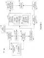
- Figure 1schematically illustrates an example ultrasound imaging system 100.
- the ultrasound imaging system 100includes a transducer array 102 with an array of transducer elements 103, which are configured to transmit ultrasound signals and receive echo signals.
- the array of transducer elements 103is a 1D array with 64, 192, etc. elements.
- the array of transducer elements 103is a 2D array with 32x32, 64x64, etc. elements. It is to be appreciated that the 1D and/or 2D arrays of transducer elements 103 can include more or less elements.
- the transducer array 102can be linear, curved, and/or otherwise shaped, and/or fully populated and/or sparse.
- Transmit circuitry 104generates pulses that excite a predetermined set of the transducer elements 103 to emit one or more ultrasound beams into a scan field of view, and receive circuitry 106 receives echoes generated in response to the transmitted ultrasound beams interacting with (generally stationary and/or flowing) structure in the scan field of view.
- the transmit circuitry 104is operated so that an axial pulse-echo field oscillates in the axial direction along the axis of the emitted ultrasound beam and at least one lateral or transverse (i.e., azimuth and/or elevation) pulse-echo field oscillates in a transverse direction, which is generally perpendicular to the emitted ultrasound beam, and different sets of elements 103 (e.g., sets of thirty-two (32) elements, etc.) receive echoes corresponding to the different pulse-echo fields.
- elements 103e.g., sets of thirty-two (32) elements, etc.
- Operation of the transmit circuitry 104 and the receive circuitry 106can be achieved using the transverse oscillation (TO) approach.
- the TO approach with respect to the axial and one transverse directionsis discussed in J. A. Jensen and P. Munk, "A New Method for Estimation of Velocity Vectors," IEEE Trans. Ultrason., Ferroelec., Freq. Contr., vol. 45, pp. 837-851 (1998 ), J. Udesen and J. A. Jensen, "Investigation of Transverse Oscillation Method,” IEEE Trans. Ultrason., Ferroelec., Freq. Contr., vol.
- a beamformer 108processes the echoes, for example, by applying time delays, weighting the channels, summing, and/or otherwise processing the received echoes.
- the illustrated beamformer 312also produces data for generating data for constructing images in A-mode, B-mode, and/or other modes.
- a spectral velocity estimator 110processes the beamformed data and estimates a velocity spectrum.
- a second spectral velocity estimator 114estimates a velocity spectrum based on the TO approach in which a pulse-echo oscillation transverse to the ultrasound beam is made during emission or in receive processing, and a velocity spectrum estimation is made based on a correlation of the received signal.
- the second spectral velocity estimator 114estimates a velocity spectrum, in one instance, based on auto and cross-correlation functions of the received signals (referred to herein as a second order approach), and, in another instance, based on auto-correlation functions of the received signals, either without an axial or without a lateral velocity component (referred to herein as a fourth order approach).
- Both the second order and the fourth order approachescan reliably determine the velocity at 90 degrees, unlike an estimation based on EQUATION 1 which, at 90 degrees, yields zero velocity.
- an operatorcan orient the transducer array 102 in any direction and still measure velocity.
- the velocity rangetends to be higher for the fourth order approach relative to the estimation based on EQUATION 1 as the lateral wavelength is larger than the axial wavelength. This may be beneficial for either keeping the pulse repetition frequency low or for maintaining a high maximum detectable velocity.
- the spectral velocity estimator 110can be implemented via a processor(s) (e.g., microprocessor, central processing unit or cpu, etc.) of a computing system(s) executing a computer readable instruction(s) encoded or embedded on a computer readable storage medium such as physical memory or other non-transitory medium. Additionally or alternatively, at least one instruction can be carried by a carrier wave, a signal, or other transitory or non-computer readable storage medium.
- a processor(s)e.g., microprocessor, central processing unit or cpu, etc.
- a computer readable instruction(s) encoded or embedded on a computer readable storage mediumsuch as physical memory or other non-transitory medium.
- at least one instructioncan be carried by a carrier wave, a signal, or other transitory or non-computer readable storage medium.
- a spectral velocity estimation selector 116selects one of the velocity spectrums, either the velocity spectrum from the first spectral velocity estimator 112 or the velocity spectrum from the second spectral velocity estimator 114, for visual presentation. In one instance, the selection between the two spectra is based on an estimated angle at the range gate, which can be obtained using a TO estimator without additional beamforming.
- the selected velocity spectrumcan be presented via a display 118, for example, as velocity distribution as a function of time.
- the spectral velocity estimation selector 116selects the velocity spectrum from the first spectral velocity estimator 112 or the spectral velocity estimation from the second spectral velocity estimator 114 based on a predetermined angle threshold.
- the predetermined angle thresholdis 60 degrees
- the spectral velocity estimation selector 116selects the spectral velocity estimation from the first spectral velocity estimator 112 when the estimated angle is less than the threshold and selects the spectral velocity estimation from the second spectral velocity estimator 114 otherwise.
- Other suitable anglessuch as 50, 70 or an angle there between are also contemplated herein.
- the thresholdcan be default, protocol specific, user defined, etc.
- An image processor 120processes the beamformed data, generating image data. For example, for B-mode, the image processor 120 processes the data and generates a sequence of focused, coherent echo samples along focused scanlines of a scanplane. Other modes are also contemplated herein.
- the image processor 120may also be configured to process the scanlines to lower speckle and/or improve specular reflector delineation via spatial compounding and/or perform other processing such as FIR filtering, IIR filtering, etc.
- a scan converter 122scan converts the image data, generating data for display, e.g., by converting the data to the coordinate system of the display 118.
- the image datacan additionally or alternatively be presented via the display 118.
- Such presentationcan be in an interactive graphical user interface (GUI), which allows the user to selectively rotate, scale, and/or manipulate the displayed data.
- GUIgraphical user interface
- Such interactioncan be through a mouse, a keyboard, touch-screen controls, etc.
- a controller 124controls one or more of the transmit circuitry 104 or receive circuitry 106. Such control can be based on available modes of operation (e.g., spectrogram, B-mode, etc.) of the system 100. A particular mode can be activated by one or more signals indicative of input from a user via a user interface (UI) 126.
- the UI 126may include one or more input devices (e.g., a button, a knob, a slider, a touch pad, etc.) and/or one or more output devices (e.g., a display screen, lights, a speaker, etc.).
- Figures 2, 3 and 4illustrate examples of the spectral velocity estimator 110.
- Figure 2shows an example of the first spectral velocity estimator 112
- Figures 3 and 4shows examples of the second spectral velocity estimator 114.
- the first spectral velocity estimator 112includes a velocity determiner 202, which utilizes EQUATION 1 to determine the velocity of flowing structure of interest.
- the first spectral velocity estimator 112further includes Fourier transform 204, which is applied to the axial velocity to determine the spectral velocity.
- the velocity distributionis visually displayed as a function of time when the output of the first spectral velocity estimator 112 is selected by the spectral velocity estimation selector 116 ( Figure 1 ).
- the TO approachcan yield two beams focused in parallel, namely, an in-phase (I) component and a quadrature (Q) component.
- the second spectral velocity estimator 114includes an autocorrelation determiner 302, which determines an autocorrelation of the received signal based on EQUATION 9:
- the velocitycan be found using, for example, the approach discussed in O. Bonnefous, P. Pesque and X. Bernard: "A new velocity estimator for color flow mapping", Proc. IEEE Ultrasonics Symposium, pp. 855-860, 1986 , T. Loupas, J. T. Powers, R. W. Gill: An axial velocity estimator for ultrasound blood flow imaging, based on a full evaluation of the Doppler equation by means of a two-dimensional autocorrelation approach, IEEE Trans. on Ultrasonics, Ferroelec. and Freq. control, vol. 43, pp.
- the approach described in connection with Figure 3is referred to herein as the second order approach.
- the axial componentis eliminated
- EQUATION 13the lateral component is eliminated.
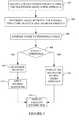
- Figure 5illustrates an example method for employing the ultrasound imaging system discussed herein.
- ultrasound imaging datais obtained using the TO approach.
- the angle ⁇ between the velocity vector of the flowing structure and the ultrasound beamis estimated.
- the estimated angleis compared with a pre-determined angle threshold.
- the thresholdhas value in a range between 50 and 70 degrees.
- a velocity determinerdetermines a velocity of the flowing structure based on EQUATION 1, at 512, a Fourier transform is applied to the velocity, and at 514, the velocity distribution is displayed as a function of time.
- acts 504 -508are performed after acts 510, 512 and 516, and one of the estimations is selected based on an outcome of act 508.
- the methods described hereinmay be implemented via one or more processors executing one or more computer readable instructions encoded or embodied on computer readable storage medium such as physical memory which causes the one or more processors to carry out the various acts and/or other functions and/or acts. Additionally or alternatively, the one or more processors can execute instructions carried by transitory medium such as a signal or carrier wave.
Landscapes
- Engineering & Computer Science (AREA)
- Physics & Mathematics (AREA)
- Health & Medical Sciences (AREA)
- Radar, Positioning & Navigation (AREA)
- Remote Sensing (AREA)
- Life Sciences & Earth Sciences (AREA)
- Acoustics & Sound (AREA)
- General Physics & Mathematics (AREA)
- Computer Networks & Wireless Communication (AREA)
- Radiology & Medical Imaging (AREA)
- Animal Behavior & Ethology (AREA)
- Pathology (AREA)
- Biophysics (AREA)
- Biomedical Technology (AREA)
- Heart & Thoracic Surgery (AREA)
- Medical Informatics (AREA)
- Molecular Biology (AREA)
- Surgery (AREA)
- Nuclear Medicine, Radiotherapy & Molecular Imaging (AREA)
- General Health & Medical Sciences (AREA)
- Public Health (AREA)
- Veterinary Medicine (AREA)
- Aviation & Aerospace Engineering (AREA)
- Computer Vision & Pattern Recognition (AREA)
- Hematology (AREA)
- Multimedia (AREA)
- Ultra Sonic Daignosis Equipment (AREA)
Description
- The following relates to angle independent velocity spectrum determination and is described with particular application to ultrasound imaging.
- An ultrasound scanner has been used to estimate a velocity spectrum for flowing structure in an object or subject of interest at a given depth and visually present the velocity distribution as a function of time in a spectrogram. The spectrogram has been calculated by measuring a sampled signal at the given depth and then employing a Fourier transform on the received data. This is discussed in Baker, "Pulsed ultrasonic Doppler blood-flow sensing," IEEE Trans. Son. Ultrason., SU-17:170-185 (1970),Evans et al., "Doppler Ultrasound, Physics, Instrumentation, and Clinical Applications,: John Wiley & Sons, New York (1989), andJensen, "Estimation of Blood Velocities Using Ultrasound: A Signal Processing Approach," Cambridge University Press, New York (1996).
- For the display, the spectra are stacked side-by-side to show the time evolution of the velocity distribution. The relation between the velocity of the flowing structure and the measured frequency (fp) can be represented as shown in EQUATION 1:

- Aspects of the application address the above matters, and others.
- In one aspect, an ultrasound imaging system includes a transducer array that emits an ultrasound beam and produces at least one transverse pulse-echo field that oscillates in a direction transverse to the emitted ultrasound beam and that receive echoes produced in response thereto, a first spectral velocity estimator that determines an axial velocity of a flowing structure from a frequency of the emitted ultrasound beam, a measured frequency and the speed of sound, and applies a Fourier transform to the axial velocity to determine a velocity spectrum, and, a second spectral velocity estimator that determines, based on a transverse oscillation approach, a power density spectrum for the flowing structure using the received echoes, and, a spectral velocity estimation selector that selects the velocity spectrum for display as a first velocity distribution as a function of time when the angle is in a range from zero to 70 degrees, and, the power density spectrum for display as a second velocity distribution as a function of time when the angle is greater than seventy degrees.
- In another aspect, a method of processing ultrasound echoes includes receiving echoes in response to emitting an ultrasound beam and at least one transverse pulse-echo field that oscillates in a direction transverse to the emitted ultrasound beam, determining a velocity spectrum for the flowing structure with a frequency of the emitted ultrasound beam, a measured frequency and the speed of sound, applying a Fourier transform to the axial velocity to determine a velocity spectrum, determining, based on a transverse oscillation approach, a power density spectrum for flowing structure using the received echoes, selecting the velocity spectrum for display as a first velocity distribution as a function of time when the angle is in a range from between zero and seventy degrees, and selecting the power density spectrum for display as a second velocity distribution as a function of time when the angle is greater than seventy degrees.
- Those skilled in the art will recognize still other aspects of the present application upon reading and understanding the attached description.
- The application is illustrated by way of example and not limited by the figures of the accompanying drawings, in which like references indicate similar elements and in which:
Figure 1 illustrates an example ultrasound imaging scanner that includes a spectral velocity estimator with a first spectral velocity estimator and a second spectral velocity estimator, which estimates spectral velocities, even where the angle between the velocity vector of the structure and the ultrasound beam is ninety degrees.Figure 2 illustrates an example of the first spectral velocity estimator which determines a spectral velocity based on emitted ultrasound beam frequency and a measured frequency;Figure 3 illustrates an example of the second spectral velocity estimator which determines a spectral velocity based on a second order approach;Figure 4 illustrates an example of the second spectral velocity estimator which determines a spectral velocity based on a fourth order approach;Figure 5 illustrates a method in accordance with the spectral velocity estimator embodiments disclosed herein.Figure 1 schematically illustrates an exampleultrasound imaging system 100.- The
ultrasound imaging system 100 includes atransducer array 102 with an array oftransducer elements 103, which are configured to transmit ultrasound signals and receive echo signals. In one non-limiting instance, the array oftransducer elements 103 is a 1D array with 64, 192, etc. elements. In another instance, the array oftransducer elements 103 is a 2D array with 32x32, 64x64, etc. elements. It is to be appreciated that the 1D and/or 2D arrays oftransducer elements 103 can include more or less elements. Furthermore, thetransducer array 102 can be linear, curved, and/or otherwise shaped, and/or fully populated and/or sparse. Transmit circuitry 104 generates pulses that excite a predetermined set of thetransducer elements 103 to emit one or more ultrasound beams into a scan field of view, and receivecircuitry 106 receives echoes generated in response to the transmitted ultrasound beams interacting with (generally stationary and/or flowing) structure in the scan field of view. In one instance, thetransmit circuitry 104 is operated so that an axial pulse-echo field oscillates in the axial direction along the axis of the emitted ultrasound beam and at least one lateral or transverse (i.e., azimuth and/or elevation) pulse-echo field oscillates in a transverse direction, which is generally perpendicular to the emitted ultrasound beam, and different sets of elements 103 (e.g., sets of thirty-two (32) elements, etc.) receive echoes corresponding to the different pulse-echo fields.- Operation of the
transmit circuitry 104 and the receivecircuitry 106, as discussed in the preceding paragraph, with respect to emitting multiple different oscillation fields that are transverse to each other, can be achieved using the transverse oscillation (TO) approach. The TO approach with respect to the axial and one transverse directions is discussed inJ. A. Jensen and P. Munk, "A New Method for Estimation of Velocity Vectors," IEEE Trans. Ultrason., Ferroelec., Freq. Contr., vol. 45, pp. 837-851 (1998),J. Udesen and J. A. Jensen, "Investigation of Transverse Oscillation Method," IEEE Trans. Ultrason., Ferroelec., Freq. Contr., vol. 53, pp. 959-971 (2006),EP19970928135 WO/2000/068678A1 , title "Estimation of vector velocity." The TO approach with respect to the axial and multiple transverse directions is discussed in International patent application serial numberPCT/IB2011/002383 , titled Three Dimensional (3D) Transverse Oscillation Vector Velocity Ultrasound Imaging, and filed October 12, 2011. Abeamformer 108 processes the echoes, for example, by applying time delays, weighting the channels, summing, and/or otherwise processing the received echoes. This includes processing the echoes and producing data for determining a velocity spectrum for flowing structure in the axial and at least one of the azimuth or elevation directions. The illustrated beamformer 312 also produces data for generating data for constructing images in A-mode, B-mode, and/or other modes. - A
spectral velocity estimator 110 processes the beamformed data and estimates a velocity spectrum. A firstspectral velocity estimator 112 estimates a velocity spectrum based on EQUATION 1. The output of the firstspectral velocity estimator 112 is employed when the angle between the velocity vector of the flowing structure and the ultrasound beam (i.e.,Θ) is less than ninety (90) degrees, for example, in a range from zero (0) to seventy (70) degrees. Angle correction can be employed for Θ > 0. At Θ = 90 degrees, as discussed herein, EQUATION 1 cannot be used to estimate a velocity. - A second
spectral velocity estimator 114 estimates a velocity spectrum based on the TO approach in which a pulse-echo oscillation transverse to the ultrasound beam is made during emission or in receive processing, and a velocity spectrum estimation is made based on a correlation of the received signal. The secondspectral velocity estimator 114 estimates the velocity spectrum as a function of time, like the firstspectral velocity estimator 112, but can additionally estimate a velocity even at Θ = 90 degrees. - As described in greater below, the second
spectral velocity estimator 114 estimates a velocity spectrum, in one instance, based on auto and cross-correlation functions of the received signals (referred to herein as a second order approach), and, in another instance, based on auto-correlation functions of the received signals, either without an axial or without a lateral velocity component (referred to herein as a fourth order approach). - Both the second order and the fourth order approaches can reliably determine the velocity at 90 degrees, unlike an estimation based on EQUATION 1 which, at 90 degrees, yields zero velocity. Thus, an operator can orient the
transducer array 102 in any direction and still measure velocity. Furthermore, the velocity range tends to be higher for the fourth order approach relative to the estimation based on EQUATION 1 as the lateral wavelength is larger than the axial wavelength. This may be beneficial for either keeping the pulse repetition frequency low or for maintaining a high maximum detectable velocity. - The
spectral velocity estimator 110 can be implemented via a processor(s) (e.g., microprocessor, central processing unit or cpu, etc.) of a computing system(s) executing a computer readable instruction(s) encoded or embedded on a computer readable storage medium such as physical memory or other non-transitory medium. Additionally or alternatively, at least one instruction can be carried by a carrier wave, a signal, or other transitory or non-computer readable storage medium. - A spectral
velocity estimation selector 116 selects one of the velocity spectrums, either the velocity spectrum from the firstspectral velocity estimator 112 or the velocity spectrum from the secondspectral velocity estimator 114, for visual presentation. In one instance, the selection between the two spectra is based on an estimated angle at the range gate, which can be obtained using a TO estimator without additional beamforming. The selected velocity spectrum can be presented via adisplay 118, for example, as velocity distribution as a function of time. - In one non-limiting instance, the spectral
velocity estimation selector 116 selects the velocity spectrum from the firstspectral velocity estimator 112 or the spectral velocity estimation from the secondspectral velocity estimator 114 based on a predetermined angle threshold. For example, in one instance, the predetermined angle threshold is 60 degrees, and the spectralvelocity estimation selector 116 selects the spectral velocity estimation from the firstspectral velocity estimator 112 when the estimated angle is less than the threshold and selects the spectral velocity estimation from the secondspectral velocity estimator 114 otherwise. Other suitable angles such as 50, 70 or an angle there between are also contemplated herein. The threshold can be default, protocol specific, user defined, etc. - An
image processor 120 processes the beamformed data, generating image data. For example, for B-mode, theimage processor 120 processes the data and generates a sequence of focused, coherent echo samples along focused scanlines of a scanplane. Other modes are also contemplated herein. Theimage processor 120 may also be configured to process the scanlines to lower speckle and/or improve specular reflector delineation via spatial compounding and/or perform other processing such as FIR filtering, IIR filtering, etc. - A
scan converter 122 scan converts the image data, generating data for display, e.g., by converting the data to the coordinate system of thedisplay 118. The image data can additionally or alternatively be presented via thedisplay 118. Such presentation can be in an interactive graphical user interface (GUI), which allows the user to selectively rotate, scale, and/or manipulate the displayed data. Such interaction can be through a mouse, a keyboard, touch-screen controls, etc. - A
controller 124 controls one or more of the transmitcircuitry 104 or receivecircuitry 106. Such control can be based on available modes of operation (e.g., spectrogram, B-mode, etc.) of thesystem 100. A particular mode can be activated by one or more signals indicative of input from a user via a user interface (UI) 126. TheUI 126 may include one or more input devices (e.g., a button, a knob, a slider, a touch pad, etc.) and/or one or more output devices (e.g., a display screen, lights, a speaker, etc.). Figures 2, 3 and 4 illustrate examples of thespectral velocity estimator 110.Figure 2 shows an example of the firstspectral velocity estimator 112, andFigures 3 and 4 shows examples of the secondspectral velocity estimator 114.- In
Figure 2 , the firstspectral velocity estimator 112 includes avelocity determiner 202, which utilizes EQUATION 1 to determine the velocity of flowing structure of interest. The firstspectral velocity estimator 112 further includesFourier transform 204, which is applied to the axial velocity to determine the spectral velocity. The velocity distribution is visually displayed as a function of time when the output of the firstspectral velocity estimator 112 is selected by the spectral velocity estimation selector 116 (Figure 1 ). - For
Figures 3 and 4 , the TO approach can yield two beams focused in parallel, namely, an in-phase (I) component and a quadrature (Q) component. This complex signal can, at one fixed depth, be described as shown in EQUATION 2:

- The temporal Hilbert transform of EQUATION 1 is shown in EQUATION 4:


- In
Figure 3 , the secondspectral velocity estimator 114 includes anautocorrelation determiner 302, which determines an autocorrelation of the received signal based on EQUATION 9:


- The modulation of the cross-correlation function by the factor exp(j2πkTprffp) can be compensated for by estimating the axial velocity and therebyfp, and then multiplyR12(k) by the compensation factorRc(k) = exp(j2πrkTprffp). The axial velocity can be found from a normally focused line lying between the two spatial beams and then employing an autocorrelation estimator, rending EQUATION 10:

- In
Figure 3 , the secondspectral velocity estimator 114 further includes a powerdensity spectrum determiner 304, which determines a velocity spectrum based on EQUATION 11:
Figure 3 is referred to herein as the second order approach. - In
Figure 4 , the secondspectral velocity estimator 114 includes anautocorrelation determiner 402, which determines an autocorrelation of the received signal based on EQUATION 12 or 13 (EQUATION 13 being the complex conjugate of EQUATION 12):


- In
Figure 4 , the secondspectral velocity estimator 114 further includes a powerdensity spectrum determiner 404, which determines a velocity spectrum based on EQUATION 14:
Figure 4 is referred to herein as the fourth order approach. Figure 5 illustrates an example method for employing the ultrasound imaging system discussed herein.- It is to be understood that the following acts are provided for explanatory purposes and are not limiting. As such, one or more of the acts may be omitted, one or more acts may be added, one or more acts may occur in a different order (including simultaneously with another act), etc.
- At 502, ultrasound imaging data is obtained using the TO approach.
- At 504, the angle Θ between the velocity vector of the flowing structure and the ultrasound beam is estimated.
- At 506, the estimated angle is compared with a pre-determined angle threshold. As discussed herein, in one instance, the threshold has value in a range between 50 and 70 degrees.
- At 508, it is determined whether the estimated angle satisfies the threshold.
- If not, then, at 510, a velocity determiner determines a velocity of the flowing structure based on EQUATION 1, at 512, a Fourier transform is applied to the velocity, and at 514, the velocity distribution is displayed as a function of time.
- If so, then at 516 either the second order power density spectrum (
Figure 3 ) or the fourth order power density spectrum (Figure 4 ) is employed to determine velocity spectrum, and at 514 the velocity distribution is displayed as a function of time. - In a variation, acts 504 -508 are performed after
acts act 508. - The methods described herein may be implemented via one or more processors executing one or more computer readable instructions encoded or embodied on computer readable storage medium such as physical memory which causes the one or more processors to carry out the various acts and/or other functions and/or acts. Additionally or alternatively, the one or more processors can execute instructions carried by transitory medium such as a signal or carrier wave.
- The application has been described with reference to various embodiments. Modifications and alterations will occur to others upon reading the application. It is intended that the invention be construed as including all such modifications and alterations, including insofar as they come within the scope of the appended claims.


Claims (15)
- An ultrasound imaging system (100), comprising:a transducer array (102) configured:-to emit an ultrasound beam,to produce at least one transverse pulse-echo field that oscillates in a direction transverse to the emitted ultrasound beam, andto receive echoes produced in response thereto;a first spectral velocity estimator (112) configured to determine an axial velocity of a flowing structure from a frequency of the emitted ultrasound beam, a measured frequency and the speed of sound, and to apply a Fourier transform (204) to the axial velocity to determine a velocity spectrum; anda second spectral velocity estimator (114) configured to determine, based on a transverse oscillation approach, a power density spectrum for the flowing structure using the received echoes; anda spectral velocity estimation selector (116) configured to select the velocity spectrum for display as a first velocity distribution as a function of time when the angle between the velocity vector of the flowing structure and the ultrasound beam is in a range from between zero and seventy degrees, and, to select the power density spectrum for display as a second velocity distribution as a function of time when the angle is greater than seventy degrees.
- The system of claim 1, wherein the second spectral velocity estimator (114) is configured to determine the power density spectrum based on an autocorrelation of the received echoes.
- The system of claim 2, wherein the second spectral velocity estimator (114) is configured to determine the autocorrelation based on a cross-correlation between spatial in-phase and quadrature signals.
- The system of claim 3, wherein the second spectral velocity estimator (114) is configured to compensate for a modulation of the cross-correlation by multiplying the cross-correlation by a compensation factor.
- The system of claim 4, wherein the compensation factor is based on an axial velocity estimated from a normally focused line lying between two spatial beams and employing an autocorrelation estimator.
- The system of claim 2, wherein the second spectral velocity estimator (114) is configured to determine the autocorrelation based on an autocorrelation of spatial in-phase signals and an autocorrelation of quadrature signals.
- The system of claim 6, wherein the autocorrelation does not include an axial component.
- The system of claim 2, wherein the second spectral velocity estimator (114) is configured to determine the autocorrelation based on an autocorrelation of spatial in-phase signals and a complex conjugate of an autocorrelation of quadrature signals.
- The system of claim 8, wherein the autocorrelation does not include a lateral component.
- A method of processing ultrasound echoes, comprising:emitting an ultrasound beam,producing at least one transverse pulse-echo field that oscillates in a direction transverse to the emitted ultrasound beam,receiving echoes produced in response to the emitted ultrasound beam;determining an axial velocity of a flowing structure from a frequency of the emitted ultrasound beam, a measured frequency and the speed of sound;applying a Fourier transform to the axial velocity to determine a velocity spectrum;determining, based on a transverse oscillation approach, a power density spectrum for the flowing structure using the received echoes;selecting the velocity spectrum for display as a first velocity distribution as a function of time when the angle between the velocity vector of the flowing structure and the ultrasound beam is in a range from between zero and seventy degrees; andselecting the power density spectrum for display as a second velocity distribution as a function of time when the angle is greater than seventy degrees.
- The method of claim 10, further comprising:
determining the power density spectrum based on an autocorrelation of the echoes. - The system of claim 11, further comprising determining the autocorrelation based on a cross-correlation between spatial in-phase and quadrature signals.
- The system of claim 12, further comprising compensating for a modulation of the cross-correlation by multiplying the cross-correlation by a compensation factor.
- The system of claim 11, further comprising determining the autocorrelation based on an autocorrelation of spatial in-phase signals and an autocorrelation of quadrature signals.
- The system of claim 11, further comprising determining the autocorrelation based on an autocorrelation of spatial in-phase signals and a complex conjugate of an autocorrelation of quadrature signals.
Applications Claiming Priority (1)
| Application Number | Priority Date | Filing Date | Title |
|---|---|---|---|
| PCT/IB2012/002527WO2014083373A1 (en) | 2012-11-28 | 2012-11-28 | Angle independent velocity spectrum determination |
Publications (2)
| Publication Number | Publication Date |
|---|---|
| EP2926147A1 EP2926147A1 (en) | 2015-10-07 |
| EP2926147B1true EP2926147B1 (en) | 2018-08-08 |
Family
ID=47563540
Family Applications (1)
| Application Number | Title | Priority Date | Filing Date |
|---|---|---|---|
| EP12816329.2ANot-in-forceEP2926147B1 (en) | 2012-11-28 | 2012-11-28 | Angle independent velocity spectrum determination |
Country Status (3)
| Country | Link |
|---|---|
| US (2) | US9702972B2 (en) |
| EP (1) | EP2926147B1 (en) |
| WO (1) | WO2014083373A1 (en) |
Families Citing this family (15)
| Publication number | Priority date | Publication date | Assignee | Title |
|---|---|---|---|---|
| EP2926147B1 (en)* | 2012-11-28 | 2018-08-08 | B-K Medical ApS | Angle independent velocity spectrum determination |
| WO2016139515A1 (en)* | 2015-03-02 | 2016-09-09 | B-K Medical Aps | Non-invasive estimation of intravascular pressure changes using vector velocity ultrasound (us) |
| US11020085B2 (en) | 2015-08-27 | 2021-06-01 | Koninklijke Philips N.V. | Spectral doppler processing with adaptive sample window size |
| KR102380216B1 (en) | 2016-11-29 | 2022-03-28 | 블랙모어 센서스 앤드 애널리틱스, 엘엘씨 | Method and system for classification of an object in a point cloud data set |
| KR102252219B1 (en) | 2016-11-30 | 2021-05-13 | 블랙모어 센서스 앤드 애널리틱스, 엘엘씨 | Adaptive scanning method and system using optical distance measurement system |
| CN110140064B (en) | 2016-11-30 | 2023-07-18 | 布莱克莫尔传感器和分析有限责任公司 | Method and system for automatic real-time adaptive scanning using optical ranging system |
| EP3548841A4 (en) | 2016-11-30 | 2020-06-10 | Blackmore Sensors And Analytics Inc. | Method and system for doppler detection and doppler correction of optical chirped range detection |
| US10422880B2 (en) | 2017-02-03 | 2019-09-24 | Blackmore Sensors and Analytics Inc. | Method and system for doppler detection and doppler correction of optical phase-encoded range detection |
| US10705210B2 (en)* | 2017-05-31 | 2020-07-07 | B-K Medical Aps | Three-dimensional (3-D) imaging with a row-column addressed (RCA) transducer array using synthetic aperture sequential beamforming (SASB) |
| US10401495B2 (en) | 2017-07-10 | 2019-09-03 | Blackmore Sensors and Analytics Inc. | Method and system for time separated quadrature detection of doppler effects in optical range measurements |
| CN115079195A (en) | 2018-04-23 | 2022-09-20 | 布莱克莫尔传感器和分析有限责任公司 | Method and system for controlling autonomous vehicle with coherent range-doppler optical sensor |
| US11822010B2 (en) | 2019-01-04 | 2023-11-21 | Blackmore Sensors & Analytics, Llc | LIDAR system |
| CN110456362B (en)* | 2019-07-17 | 2021-07-06 | 北京大学 | A method and system for target acoustic imaging and velocity measurement based on pulse pair emission |
| US12130363B2 (en) | 2022-02-03 | 2024-10-29 | Aurora Operations, Inc. | LIDAR system |
| CN115721336B (en)* | 2022-11-24 | 2025-04-08 | 中国科学院深圳先进技术研究院 | Ultrasonic plane wave imaging method, device and equipment |
Family Cites Families (7)
| Publication number | Priority date | Publication date | Assignee | Title |
|---|---|---|---|---|
| JP4100709B2 (en)* | 1996-07-02 | 2008-06-11 | ベー コー メディカル アクティーゼルスカブ | Apparatus for determining the motion and velocity of moving objects |
| AU4393200A (en) | 1999-05-10 | 2000-11-21 | B-K Medical A/S | Estimation of vector velocity |
| US6535835B1 (en)* | 2000-01-31 | 2003-03-18 | Ge Medical Systems Global Technology Company, Llc | Angle independent ultrasound volume flow measurement |
| US9066679B2 (en)* | 2004-08-31 | 2015-06-30 | University Of Washington | Ultrasonic technique for assessing wall vibrations in stenosed blood vessels |
| EP1784130A4 (en)* | 2004-08-31 | 2014-11-19 | Univ Washington | ULTRASONIC TECHNIQUE FOR EVALUATING VIBRATIONS OF WALLS IN STENOSED BLOOD VESSELS |
| US9192359B2 (en)* | 2011-10-19 | 2015-11-24 | Verasonics, Inc. | Estimation and display for vector doppler imaging using plane wave transmissions |
| EP2926147B1 (en)* | 2012-11-28 | 2018-08-08 | B-K Medical ApS | Angle independent velocity spectrum determination |
- 2012
- 2012-11-28EPEP12816329.2Apatent/EP2926147B1/ennot_activeNot-in-force
- 2012-11-28USUS14/646,770patent/US9702972B2/enactiveActive
- 2012-11-28WOPCT/IB2012/002527patent/WO2014083373A1/enactiveApplication Filing
- 2017
- 2017-06-26USUS15/632,825patent/US10359515B2/enactiveActive
Non-Patent Citations (2)
| Title |
|---|
| BAKER D W: "Pulsed Ultrasonic Doppler Blood-Flow Sensing", IEEE TRANSACTIONS ON SONICS AND ULTRASONICS, IEEE, US, vol. 17, no. 3, 1 July 1970 (1970-07-01), pages 170 - 184, XP011403875, ISSN: 0018-9537, DOI: 10.1109/T-SU.1970.29558* |
| LIFANG WANG ET AL: "Spectral Simulation Analysis of Doppler Ultrasound Blood Flow Signals from Local Expansion Artery", INFORMATION TECHNOLOGY AND APPLICATIONS (IFITA), 2010 INTERNATIONAL FORUM ON, IEEE, PISCATAWAY, NJ, USA, 16 July 2010 (2010-07-16), pages 113 - 116, XP031801134, ISBN: 978-1-4244-7621-3* |
Also Published As
| Publication number | Publication date |
|---|---|
| US9702972B2 (en) | 2017-07-11 |
| EP2926147A1 (en) | 2015-10-07 |
| US20150331103A1 (en) | 2015-11-19 |
| WO2014083373A1 (en) | 2014-06-05 |
| US20170293029A1 (en) | 2017-10-12 |
| US10359515B2 (en) | 2019-07-23 |
Similar Documents
| Publication | Publication Date | Title |
|---|---|---|
| US10359515B2 (en) | Angle independent velocity spectrum determination | |
| JP4100709B2 (en) | Apparatus for determining the motion and velocity of moving objects | |
| US9351707B2 (en) | Methods and apparatus to determine shear wave propagation property | |
| JP5882447B2 (en) | Ultrasonic imaging method and ultrasonic imaging apparatus | |
| EP2830508B1 (en) | Methods and apparatus for ultrasound imaging | |
| US9211111B2 (en) | Determination of shear wave characteristics | |
| US9636086B2 (en) | Three dimensional (3D) transverse oscillation vector velocity ultrasound imaging | |
| EP2610641B1 (en) | Ultrasound and system for forming a Doppler ultrasound image | |
| CN107049361B (en) | Sound velocity imaging using shear waves | |
| US9855022B2 (en) | 3-D flow estimation using row-column addressed transducer arrays | |
| EP2609870A1 (en) | Providing turbulent flow information based on vector doppler in ultrasound system | |
| KR20200030463A (en) | Angles for ultrasound-based shear wave imaging | |
| US11112500B2 (en) | Ultrasound imaging flow vector velocity estimation with directional transverse oscillation | |
| EP2610640B1 (en) | Ultrasound system and method for detecting vector information using transmission delays | |
| US10448926B2 (en) | Transverse oscillation vector estimation in ultrasound imaging | |
| US10302752B2 (en) | Vector velocity estimation using transverse oscillation (TO) and synthetic aperture sequential beamforming (SASB) | |
| Maru et al. | 3P5-1 Numerical simulation for determining minimum beam steering angle for estimation of blood flow velocity vectors |
Legal Events
| Date | Code | Title | Description |
|---|---|---|---|
| PUAI | Public reference made under article 153(3) epc to a published international application that has entered the european phase | Free format text:ORIGINAL CODE: 0009012 | |
| 17P | Request for examination filed | Effective date:20150604 | |
| AK | Designated contracting states | Kind code of ref document:A1 Designated state(s):AL AT BE BG CH CY CZ DE DK EE ES FI FR GB GR HR HU IE IS IT LI LT LU LV MC MK MT NL NO PL PT RO RS SE SI SK SM TR | |
| AX | Request for extension of the european patent | Extension state:BA ME | |
| DAX | Request for extension of the european patent (deleted) | ||
| 17Q | First examination report despatched | Effective date:20160630 | |
| STAA | Information on the status of an ep patent application or granted ep patent | Free format text:STATUS: EXAMINATION IS IN PROGRESS | |
| GRAP | Despatch of communication of intention to grant a patent | Free format text:ORIGINAL CODE: EPIDOSNIGR1 | |
| STAA | Information on the status of an ep patent application or granted ep patent | Free format text:STATUS: GRANT OF PATENT IS INTENDED | |
| INTG | Intention to grant announced | Effective date:20180416 | |
| GRAS | Grant fee paid | Free format text:ORIGINAL CODE: EPIDOSNIGR3 | |
| GRAA | (expected) grant | Free format text:ORIGINAL CODE: 0009210 | |
| STAA | Information on the status of an ep patent application or granted ep patent | Free format text:STATUS: THE PATENT HAS BEEN GRANTED | |
| AK | Designated contracting states | Kind code of ref document:B1 Designated state(s):AL AT BE BG CH CY CZ DE DK EE ES FI FR GB GR HR HU IE IS IT LI LT LU LV MC MK MT NL NO PL PT RO RS SE SI SK SM TR | |
| REG | Reference to a national code | Ref country code:GB Ref legal event code:FG4D | |
| REG | Reference to a national code | Ref country code:CH Ref legal event code:EP Ref country code:AT Ref legal event code:REF Ref document number:1027618 Country of ref document:AT Kind code of ref document:T Effective date:20180815 | |
| REG | Reference to a national code | Ref country code:IE Ref legal event code:FG4D | |
| REG | Reference to a national code | Ref country code:DE Ref legal event code:R096 Ref document number:602012049598 Country of ref document:DE | |
| REG | Reference to a national code | Ref country code:NL Ref legal event code:MP Effective date:20180808 | |
| REG | Reference to a national code | Ref country code:LT Ref legal event code:MG4D | |
| REG | Reference to a national code | Ref country code:AT Ref legal event code:MK05 Ref document number:1027618 Country of ref document:AT Kind code of ref document:T Effective date:20180808 | |
| PG25 | Lapsed in a contracting state [announced via postgrant information from national office to epo] | Ref country code:GR Free format text:LAPSE BECAUSE OF FAILURE TO SUBMIT A TRANSLATION OF THE DESCRIPTION OR TO PAY THE FEE WITHIN THE PRESCRIBED TIME-LIMIT Effective date:20181109 Ref country code:BG Free format text:LAPSE BECAUSE OF FAILURE TO SUBMIT A TRANSLATION OF THE DESCRIPTION OR TO PAY THE FEE WITHIN THE PRESCRIBED TIME-LIMIT Effective date:20181108 Ref country code:NO Free format text:LAPSE BECAUSE OF FAILURE TO SUBMIT A TRANSLATION OF THE DESCRIPTION OR TO PAY THE FEE WITHIN THE PRESCRIBED TIME-LIMIT Effective date:20181108 Ref country code:SE Free format text:LAPSE BECAUSE OF FAILURE TO SUBMIT A TRANSLATION OF THE DESCRIPTION OR TO PAY THE FEE WITHIN THE PRESCRIBED TIME-LIMIT Effective date:20180808 Ref country code:IS Free format text:LAPSE BECAUSE OF FAILURE TO SUBMIT A TRANSLATION OF THE DESCRIPTION OR TO PAY THE FEE WITHIN THE PRESCRIBED TIME-LIMIT Effective date:20181208 Ref country code:AT Free format text:LAPSE BECAUSE OF FAILURE TO SUBMIT A TRANSLATION OF THE DESCRIPTION OR TO PAY THE FEE WITHIN THE PRESCRIBED TIME-LIMIT Effective date:20180808 Ref country code:PL Free format text:LAPSE BECAUSE OF FAILURE TO SUBMIT A TRANSLATION OF THE DESCRIPTION OR TO PAY THE FEE WITHIN THE PRESCRIBED TIME-LIMIT Effective date:20180808 Ref country code:NL Free format text:LAPSE BECAUSE OF FAILURE TO SUBMIT A TRANSLATION OF THE DESCRIPTION OR TO PAY THE FEE WITHIN THE PRESCRIBED TIME-LIMIT Effective date:20180808 Ref country code:LT Free format text:LAPSE BECAUSE OF FAILURE TO SUBMIT A TRANSLATION OF THE DESCRIPTION OR TO PAY THE FEE WITHIN THE PRESCRIBED TIME-LIMIT Effective date:20180808 Ref country code:RS Free format text:LAPSE BECAUSE OF FAILURE TO SUBMIT A TRANSLATION OF THE DESCRIPTION OR TO PAY THE FEE WITHIN THE PRESCRIBED TIME-LIMIT Effective date:20180808 Ref country code:FI Free format text:LAPSE BECAUSE OF FAILURE TO SUBMIT A TRANSLATION OF THE DESCRIPTION OR TO PAY THE FEE WITHIN THE PRESCRIBED TIME-LIMIT Effective date:20180808 | |
| PG25 | Lapsed in a contracting state [announced via postgrant information from national office to epo] | Ref country code:HR Free format text:LAPSE BECAUSE OF FAILURE TO SUBMIT A TRANSLATION OF THE DESCRIPTION OR TO PAY THE FEE WITHIN THE PRESCRIBED TIME-LIMIT Effective date:20180808 Ref country code:AL Free format text:LAPSE BECAUSE OF FAILURE TO SUBMIT A TRANSLATION OF THE DESCRIPTION OR TO PAY THE FEE WITHIN THE PRESCRIBED TIME-LIMIT Effective date:20180808 Ref country code:LV Free format text:LAPSE BECAUSE OF FAILURE TO SUBMIT A TRANSLATION OF THE DESCRIPTION OR TO PAY THE FEE WITHIN THE PRESCRIBED TIME-LIMIT Effective date:20180808 | |
| PG25 | Lapsed in a contracting state [announced via postgrant information from national office to epo] | Ref country code:EE Free format text:LAPSE BECAUSE OF FAILURE TO SUBMIT A TRANSLATION OF THE DESCRIPTION OR TO PAY THE FEE WITHIN THE PRESCRIBED TIME-LIMIT Effective date:20180808 Ref country code:RO Free format text:LAPSE BECAUSE OF FAILURE TO SUBMIT A TRANSLATION OF THE DESCRIPTION OR TO PAY THE FEE WITHIN THE PRESCRIBED TIME-LIMIT Effective date:20180808 Ref country code:IT Free format text:LAPSE BECAUSE OF FAILURE TO SUBMIT A TRANSLATION OF THE DESCRIPTION OR TO PAY THE FEE WITHIN THE PRESCRIBED TIME-LIMIT Effective date:20180808 Ref country code:ES Free format text:LAPSE BECAUSE OF FAILURE TO SUBMIT A TRANSLATION OF THE DESCRIPTION OR TO PAY THE FEE WITHIN THE PRESCRIBED TIME-LIMIT Effective date:20180808 Ref country code:CZ Free format text:LAPSE BECAUSE OF FAILURE TO SUBMIT A TRANSLATION OF THE DESCRIPTION OR TO PAY THE FEE WITHIN THE PRESCRIBED TIME-LIMIT Effective date:20180808 | |
| REG | Reference to a national code | Ref country code:DE Ref legal event code:R097 Ref document number:602012049598 Country of ref document:DE | |
| PG25 | Lapsed in a contracting state [announced via postgrant information from national office to epo] | Ref country code:SK Free format text:LAPSE BECAUSE OF FAILURE TO SUBMIT A TRANSLATION OF THE DESCRIPTION OR TO PAY THE FEE WITHIN THE PRESCRIBED TIME-LIMIT Effective date:20180808 Ref country code:DK Free format text:LAPSE BECAUSE OF FAILURE TO SUBMIT A TRANSLATION OF THE DESCRIPTION OR TO PAY THE FEE WITHIN THE PRESCRIBED TIME-LIMIT Effective date:20180808 Ref country code:SM Free format text:LAPSE BECAUSE OF FAILURE TO SUBMIT A TRANSLATION OF THE DESCRIPTION OR TO PAY THE FEE WITHIN THE PRESCRIBED TIME-LIMIT Effective date:20180808 | |
| PLBE | No opposition filed within time limit | Free format text:ORIGINAL CODE: 0009261 | |
| STAA | Information on the status of an ep patent application or granted ep patent | Free format text:STATUS: NO OPPOSITION FILED WITHIN TIME LIMIT | |
| REG | Reference to a national code | Ref country code:CH Ref legal event code:PL | |
| 26N | No opposition filed | Effective date:20190509 | |
| GBPC | Gb: european patent ceased through non-payment of renewal fee | Effective date:20181128 | |
| PG25 | Lapsed in a contracting state [announced via postgrant information from national office to epo] | Ref country code:MC Free format text:LAPSE BECAUSE OF FAILURE TO SUBMIT A TRANSLATION OF THE DESCRIPTION OR TO PAY THE FEE WITHIN THE PRESCRIBED TIME-LIMIT Effective date:20180808 Ref country code:LU Free format text:LAPSE BECAUSE OF NON-PAYMENT OF DUE FEES Effective date:20181128 | |
| REG | Reference to a national code | Ref country code:BE Ref legal event code:MM Effective date:20181130 | |
| REG | Reference to a national code | Ref country code:IE Ref legal event code:MM4A | |
| PG25 | Lapsed in a contracting state [announced via postgrant information from national office to epo] | Ref country code:LI Free format text:LAPSE BECAUSE OF NON-PAYMENT OF DUE FEES Effective date:20181130 Ref country code:SI Free format text:LAPSE BECAUSE OF FAILURE TO SUBMIT A TRANSLATION OF THE DESCRIPTION OR TO PAY THE FEE WITHIN THE PRESCRIBED TIME-LIMIT Effective date:20180808 Ref country code:CH Free format text:LAPSE BECAUSE OF NON-PAYMENT OF DUE FEES Effective date:20181130 | |
| PG25 | Lapsed in a contracting state [announced via postgrant information from national office to epo] | Ref country code:FR Free format text:LAPSE BECAUSE OF NON-PAYMENT OF DUE FEES Effective date:20181130 Ref country code:IE Free format text:LAPSE BECAUSE OF NON-PAYMENT OF DUE FEES Effective date:20181128 | |
| PG25 | Lapsed in a contracting state [announced via postgrant information from national office to epo] | Ref country code:BE Free format text:LAPSE BECAUSE OF NON-PAYMENT OF DUE FEES Effective date:20181130 | |
| PG25 | Lapsed in a contracting state [announced via postgrant information from national office to epo] | Ref country code:GB Free format text:LAPSE BECAUSE OF NON-PAYMENT OF DUE FEES Effective date:20181128 | |
| PG25 | Lapsed in a contracting state [announced via postgrant information from national office to epo] | Ref country code:MT Free format text:LAPSE BECAUSE OF NON-PAYMENT OF DUE FEES Effective date:20181128 | |
| PG25 | Lapsed in a contracting state [announced via postgrant information from national office to epo] | Ref country code:TR Free format text:LAPSE BECAUSE OF FAILURE TO SUBMIT A TRANSLATION OF THE DESCRIPTION OR TO PAY THE FEE WITHIN THE PRESCRIBED TIME-LIMIT Effective date:20180808 | |
| PGFP | Annual fee paid to national office [announced via postgrant information from national office to epo] | Ref country code:DE Payment date:20200130 Year of fee payment:8 | |
| PG25 | Lapsed in a contracting state [announced via postgrant information from national office to epo] | Ref country code:PT Free format text:LAPSE BECAUSE OF FAILURE TO SUBMIT A TRANSLATION OF THE DESCRIPTION OR TO PAY THE FEE WITHIN THE PRESCRIBED TIME-LIMIT Effective date:20180808 | |
| PG25 | Lapsed in a contracting state [announced via postgrant information from national office to epo] | Ref country code:CY Free format text:LAPSE BECAUSE OF FAILURE TO SUBMIT A TRANSLATION OF THE DESCRIPTION OR TO PAY THE FEE WITHIN THE PRESCRIBED TIME-LIMIT Effective date:20180808 Ref country code:HU Free format text:LAPSE BECAUSE OF FAILURE TO SUBMIT A TRANSLATION OF THE DESCRIPTION OR TO PAY THE FEE WITHIN THE PRESCRIBED TIME-LIMIT; INVALID AB INITIO Effective date:20121128 Ref country code:MK Free format text:LAPSE BECAUSE OF NON-PAYMENT OF DUE FEES Effective date:20180808 | |
| REG | Reference to a national code | Ref country code:DE Ref legal event code:R119 Ref document number:602012049598 Country of ref document:DE | |
| PG25 | Lapsed in a contracting state [announced via postgrant information from national office to epo] | Ref country code:DE Free format text:LAPSE BECAUSE OF NON-PAYMENT OF DUE FEES Effective date:20210601 | |
| P01 | Opt-out of the competence of the unified patent court (upc) registered | Effective date:20230528 |