EP2925494B1 - Teleoperation of machines having at least one actuated mechanism and one machine controller comprising a program code including instructions for transferring control of the machine from said controller to a remote control station - Google Patents
Teleoperation of machines having at least one actuated mechanism and one machine controller comprising a program code including instructions for transferring control of the machine from said controller to a remote control stationDownload PDFInfo
- Publication number
- EP2925494B1 EP2925494B1EP13811308.9AEP13811308AEP2925494B1EP 2925494 B1EP2925494 B1EP 2925494B1EP 13811308 AEP13811308 AEP 13811308AEP 2925494 B1EP2925494 B1EP 2925494B1
- Authority
- EP
- European Patent Office
- Prior art keywords
- machine
- controller
- control
- control station
- robot
- Prior art date
- Legal status (The legal status is an assumption and is not a legal conclusion. Google has not performed a legal analysis and makes no representation as to the accuracy of the status listed.)
- Active
Links
- 230000007246mechanismEffects0.000titleclaimsdescription4
- 238000004891communicationMethods0.000claimsdescription18
- 238000012546transferMethods0.000claimsdescription5
- 230000033001locomotionEffects0.000description16
- 238000000034methodMethods0.000description10
- 230000008569processEffects0.000description9
- 238000012545processingMethods0.000description7
- 230000004888barrier functionEffects0.000description3
- 239000000463materialSubstances0.000description3
- 238000003754machiningMethods0.000description2
- 238000005498polishingMethods0.000description2
- 238000007792additionMethods0.000description1
- 230000005540biological transmissionEffects0.000description1
- 230000008859changeEffects0.000description1
- 238000012217deletionMethods0.000description1
- 230000037430deletionEffects0.000description1
- 230000001419dependent effectEffects0.000description1
- 238000005516engineering processMethods0.000description1
- 231100001261hazardousToxicity0.000description1
- 239000000383hazardous chemicalSubstances0.000description1
- 230000036541healthEffects0.000description1
- 230000000977initiatory effectEffects0.000description1
- 238000007689inspectionMethods0.000description1
- 238000009434installationMethods0.000description1
- 238000012986modificationMethods0.000description1
- 230000004048modificationEffects0.000description1
- 238000012544monitoring processMethods0.000description1
- 238000007517polishing processMethods0.000description1
- 230000004044responseEffects0.000description1
- 238000005507sprayingMethods0.000description1
- 238000003466weldingMethods0.000description1
Images


Classifications
- B—PERFORMING OPERATIONS; TRANSPORTING
- B25—HAND TOOLS; PORTABLE POWER-DRIVEN TOOLS; MANIPULATORS
- B25J—MANIPULATORS; CHAMBERS PROVIDED WITH MANIPULATION DEVICES
- B25J9/00—Programme-controlled manipulators
- B25J9/16—Programme controls
- B25J9/1679—Programme controls characterised by the tasks executed
- B25J9/1689—Teleoperation
- G—PHYSICS
- G05—CONTROLLING; REGULATING
- G05B—CONTROL OR REGULATING SYSTEMS IN GENERAL; FUNCTIONAL ELEMENTS OF SUCH SYSTEMS; MONITORING OR TESTING ARRANGEMENTS FOR SUCH SYSTEMS OR ELEMENTS
- G05B2219/00—Program-control systems
- G05B2219/30—Nc systems
- G05B2219/40—Robotics, robotics mapping to robotics vision
- G05B2219/40195—Tele-operation, computer assisted manual operation
- G—PHYSICS
- G05—CONTROLLING; REGULATING
- G05B—CONTROL OR REGULATING SYSTEMS IN GENERAL; FUNCTIONAL ELEMENTS OF SUCH SYSTEMS; MONITORING OR TESTING ARRANGEMENTS FOR SUCH SYSTEMS OR ELEMENTS
- G05B2219/00—Program-control systems
- G05B2219/30—Nc systems
- G05B2219/40—Robotics, robotics mapping to robotics vision
- G05B2219/40399—Selection of master-slave operation mode
- Y—GENERAL TAGGING OF NEW TECHNOLOGICAL DEVELOPMENTS; GENERAL TAGGING OF CROSS-SECTIONAL TECHNOLOGIES SPANNING OVER SEVERAL SECTIONS OF THE IPC; TECHNICAL SUBJECTS COVERED BY FORMER USPC CROSS-REFERENCE ART COLLECTIONS [XRACs] AND DIGESTS
- Y10—TECHNICAL SUBJECTS COVERED BY FORMER USPC
- Y10S—TECHNICAL SUBJECTS COVERED BY FORMER USPC CROSS-REFERENCE ART COLLECTIONS [XRACs] AND DIGESTS
- Y10S901/00—Robots
- Y10S901/02—Arm motion controller
- Y10S901/06—Communication with another machine
- Y—GENERAL TAGGING OF NEW TECHNOLOGICAL DEVELOPMENTS; GENERAL TAGGING OF CROSS-SECTIONAL TECHNOLOGIES SPANNING OVER SEVERAL SECTIONS OF THE IPC; TECHNICAL SUBJECTS COVERED BY FORMER USPC CROSS-REFERENCE ART COLLECTIONS [XRACs] AND DIGESTS
- Y10—TECHNICAL SUBJECTS COVERED BY FORMER USPC
- Y10S—TECHNICAL SUBJECTS COVERED BY FORMER USPC CROSS-REFERENCE ART COLLECTIONS [XRACs] AND DIGESTS
- Y10S901/00—Robots
- Y10S901/30—End effector
Definitions
- This inventionrelates to the teleoperation of one or more robots or other machines with at least one actuated mechanism.
- Teleoperation of an industrial robotoccurs when the operator of the teleoperated industrial robot is located apart from the robot when the industrial robot performs work.
- An industrial robotis an automatically controlled, reprogrammable, multipurpose manipulator programmable in three or more axes. Examples of industrial robots are robots located at a fixed position that are mobile by themselves or mobile because the robot is mounted on a device that is itself mobile such as a motorized vehicle or mounted on a track or gantry etc.
- located apart from each otheris meant that the operator and teleoperated industrial robot are either within the line of sight of each other or are separated from each other by a barrier through which the operator can see the robot that is controlled by the operator, or are at a distance from each other such that the operator cannot see the robot with his or her eyes. If there is a see through barrier, the barrier separates the operator from work performed by the robot that is hazardous to the health or safety of the operator.
- the principal applications for teleoperated industrial robotsare machining, handling of hazardous materials, assembling/disassembling, operation in a contaminated environment, inspection and service, or other operations in an unmanned, harsh outdoor environment such as offshore, desert, Arctic, Antarctic, subsea and space.
- a system for teleoperation of a machine having at least one actuated mechanism and a predetermined number of degrees of freedomis defined by the appended claim 1.
- a system 10that has at least one remote robot station 12, at least one operator station 14 and at least one communication link 16 between the robot station 12 and the operator station 14.
- the physical distance between the remote robot station 12 and the operator station 14can vary from "next door” to each other to "another continent”.
- the robot station 12includes at least one robot 12a.
- Robot 12ais for example a six degree of freedom industrial robot available from ABB.
- Robot station 12also includes a robot controller 12b that includes a data interface which accepts motion commands and provides actual motion data, and optionally one or more remote sensor devices 12c that observe the robot station 12 and attached processes, such as cameras, microphones, position sensors, proximity sensors and force sensors.
- the sensor devices 12cmay either be smart sensors, that is the sensor device 12c includes data processing capability, or not smart sensors, that is, the sensor device 12c does not include data processing capability.
- the output of the sensor devicesis connected directly to robot controller 12b. If the sensor devices 12c are not smart sensors, then their output can be connected either to a computation device 18 to process the sensor device output or to the communication link 16 described in more detail below so that the sensor device output is processed in data processing device 14c.
- the robot station 12can also include as an option one or more actuators and other devices (not shown in Fig. 1 but well known to those of ordinary skill in this art), that are mounted to the robot or next to the robot, such as grippers, fixtures, welding guns, spraying guns, spotlights and conveyors.
- actuators and other devicesnot shown in Fig. 1 but well known to those of ordinary skill in this art
- the controller 12bhas the program which when executed controls the motion of the robot 12a to perform work.
- the robotmay hold a tool, not shown, which is used to perform work on a stationary or moving workpiece, not shown, or may hold the workpiece which has work performed on it by an appropriate tool.
- the remote sensor devices 12cprovide input signals to the controller 12b that the controller uses to control the robot 12a in performance of the work.
- the operator station 14has at least one teleoperation input device 14a such as joysticks or stylus-type devices which the operator uses to create continuous motion signals (position or speed signals). When force feedback is added to these devices they become haptic devices. This feedback causes a vibration in the joystick and the operator feels the force feedback in the stylus-type devices.
- teleoperation input device 14asuch as joysticks or stylus-type devices which the operator uses to create continuous motion signals (position or speed signals).
- the signals from these input devices 14aare used by the controller 12b to operate the robot 12a.
- the device sidealso has at least one display device 14b and a data processing device 14c which is connected to both the input devices 14a and the display devices 14b.
- the monitoring (display) device 14bshows actual data about the robot motion and attached processes, for example, camera images, acoustic feedback and sensor values.
- the data processing device 14cprocesses data in both directions.
- Device 14cmay for example be an industrial PC or a PLC.
- the operator station 14may also include a safety enable device (not shown in Fig. 1 ) that is separate and distinct from input devices 14a and may for example be a three position switch.
- the safety enabling deviceenables and disables power to the robot 12a and attached processes.
- the communication link 16connects the robot controller 12b and the data processing device 14c to each other.
- the communication link 16comprises one or more communication links 16-1 to 16-N.
- the communication link 16 between the operator station 14 and the robot station 12may be realized with various technologies (e.g. fiber-optic/radio/cable on different types and layers of data protocols).
- a major portion or the entire infrastructure of the communication linkmay already exist and be used for other purposes than teleoperating robots.
- Typical examplesare existing Ethernet installations with LAN and WLAN, Bluetooth, ZigBee and other wireless industrial links, point-to-point radio systems or laser-optical systems, and satellite communication links.
- System 10is operated to maintain a reliable "real-time" communication link 16 between device side 14 and the remotely located robot side 12.
- the system 10changes parameters of the communication link 16 and the robot motion, depending on the current available data rate and/or transmission time of the communication link 16.
- the operatorhas direct remote control of the motion of robot 12a and attached processes.
- real-timeas used herein is in the context of teleoperation of the motion of a robot 12a or a machine.
- the teleoperationis considered to be real-time if:
- Exceeding the maximum delaymay result in damage to the workpiece or to the robot or other equipment on the robot side.
- the teleoperated roboticis used in a grinding application and the communication delay exceeds the maximum delay, this causes the operator to remove more material from the workpiece than desired. This excess removal of material can result in damage to the workpiece.
- the communication delay exceeding the maximum delaywill cause the collision between the robot 12a and other equipment on robot side.
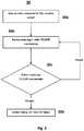
- FIG. 2there is a flowchart 20 for the main steps for transferring control during teleoperation of robot 12a from the robot side 12 to the device side 14.
- This transfer of controloccurs when a teleoperation (TELEOP) instruction is reached in the program controlling the robot 12a. Control is transferred back to the robot side 12 when the TELEOP instruction has been fully executed.
- the TELEOP instructionis an instruction which when executed gives control of robot 12a to the operator on the device side 14.
- the flowstarts at block 20a with the robot running the robot program.
- a TELEOP instructionis reached in the robot program.
- the robot side 12 at block 20csignals the device side 14 that the robot 12a is ready to receive guidance such as for example a teleoperation of the robot 12a by the operator at the device side 14.
- the device side 14acknowledges the signal received from the robot 12a and the device side 14 guides the robot 12a.
- the device side 14 at block 20esignals to robot 12a that the TELEOP task is completed.
- the robot at block 20facknowledges the signal from the device side 14 and the robot 12a resumes running the robot program.
- each user that accesses the robot during a TELEOPhas to login with specific TELEOP credentials before initiating a TELEOP session.
- TELEOP authenticationis shown in the flowchart 30 of Fig 3 .
- the device side 14connects to the remote robot 16.
- the device side 14logs in with the TELEOP credentials.
- the robot 12aconfirms the TELEOP credentials. If the credentials are not confirmed, the login is rejected and the flow returns to block 30b to await another login whose credentials will be confirmed. If the credentials are confirmed, then at block 30d the robot 12a is ready to perform the TELEOP tasks.
- Local force controlhas been used with teleoperated robots but the objective of that local force control is to coexist with the remote device control in all directions of the task frame. That is, the position and velocity reference command generated by the remote device control is modified by the force control in all 6 DOFs of the task frame. As a result, the robot stiffness is weak in all the directions. This strategy is inefficient and cannot be used where high stiffness is required in a few selected directions such as polishing and grinding. Hybrid position and force control is often used if the robot is completely controlled locally.
- the traditional hybrid control architecture(such as hybrid position and force control) is extended by the technique described below from local to teleoperation of robot 12a.
- the 6 DOFs of the task frameare partitioned into two sets. One set is controlled by the remote device 14a, and the other set is controlled either by the slave robot side force control or the position control with the user predefined motion or path.
- the task framecan be one of the predefined frames in the robot program such as the tool frame, the work object frame, the path frame, robot base frame, world frame etc. or offset from one of the predefined frames.
- Hybrid remote control architectureis very useful for tele-machining tasks. For example, in deburring, grinding or polishing processes, it is desirable that the tool orientation keeps fixed, the feed direction is controlled by the remote input device to follow the workpiece contour, and constant force is maintained in the contact normal direction between the tool and the workpiece.
- Figs. 4 and 5depict examples of hybrid combination of different controllers.
- Fig. 4shows the hybrid position control for a completely locally controlled robot in an exemplar polishing application.
- the path of the robot motionis preprogrammed.
- the robotis force controlled denoted by F only in the tool axis direction, while all the other directions are position controlled. Comparing the left and right sides of Fig. 4 shows that the force control F in the left side of that figure is replaced in the right side of that figure by device control denoted by D where P denotes Position control.
- the system designerwill consider the criteria listed above and decide which control mode will be used.
Landscapes
- Engineering & Computer Science (AREA)
- Robotics (AREA)
- Mechanical Engineering (AREA)
- Manipulator (AREA)
Description
- This invention relates to the teleoperation of one or more robots or other machines with at least one actuated mechanism.
- Teleoperation of an industrial robot occurs when the operator of the teleoperated industrial robot is located apart from the robot when the industrial robot performs work. An industrial robot is an automatically controlled, reprogrammable, multipurpose manipulator programmable in three or more axes. Examples of industrial robots are robots located at a fixed position that are mobile by themselves or mobile because the robot is mounted on a device that is itself mobile such as a motorized vehicle or mounted on a track or gantry etc.
- By located apart from each other is meant that the operator and teleoperated industrial robot are either within the line of sight of each other or are separated from each other by a barrier through which the operator can see the robot that is controlled by the operator, or are at a distance from each other such that the operator cannot see the robot with his or her eyes. If there is a see through barrier, the barrier separates the operator from work performed by the robot that is hazardous to the health or safety of the operator.
- The principal applications for teleoperated industrial robots are machining, handling of hazardous materials, assembling/disassembling, operation in a contaminated environment, inspection and service, or other operations in an unmanned, harsh outdoor environment such as offshore, desert, Arctic, Antarctic, subsea and space.
- A system for assisting in the handling of robotized machines in the context of a remote handling process is disclosed in document
FR 2 957 000 A1 - A system for teleoperation of a machine having at least one actuated mechanism and a predetermined number of degrees of freedom is defined by the appended
claim 1. Fig. 1 shows an embodiment for a system for a teleoperated industrial robot.Fig. 2 shows a flowchart for the main steps for transferring control during teleoperation of the robot shown inFig. 1 from the robot side to the device side.Fig. 3 shows a flowchart for determining when there are multiple teleoperation input devices are in use which user is the master of the teleoperation system.Figs. 4 and 5 depict examples of hybrid combination of different robot controllers.- Referring now to
Fig. 1 , there is shown asystem 10 that has at least oneremote robot station 12, at least oneoperator station 14 and at least onecommunication link 16 between therobot station 12 and theoperator station 14. The physical distance between theremote robot station 12 and theoperator station 14 can vary from "next door" to each other to "another continent". - The
robot station 12 includes at least onerobot 12a. Robot 12a is for example a six degree of freedom industrial robot available from ABB. Robot station 12 also includes arobot controller 12b that includes a data interface which accepts motion commands and provides actual motion data, and optionally one or moreremote sensor devices 12c that observe therobot station 12 and attached processes, such as cameras, microphones, position sensors, proximity sensors and force sensors. Thesensor devices 12c may either be smart sensors, that is thesensor device 12c includes data processing capability, or not smart sensors, that is, thesensor device 12c does not include data processing capability.- If the
sensor devices 12c are smart sensors then the output of the sensor devices is connected directly torobot controller 12b. If thesensor devices 12c are not smart sensors, then their output can be connected either to acomputation device 18 to process the sensor device output or to thecommunication link 16 described in more detail below so that the sensor device output is processed indata processing device 14c. - The
robot station 12 can also include as an option one or more actuators and other devices (not shown inFig. 1 but well known to those of ordinary skill in this art), that are mounted to the robot or next to the robot, such as grippers, fixtures, welding guns, spraying guns, spotlights and conveyors. - The
controller 12b has the program which when executed controls the motion of therobot 12a to perform work. As is well known, the robot may hold a tool, not shown, which is used to perform work on a stationary or moving workpiece, not shown, or may hold the workpiece which has work performed on it by an appropriate tool. Theremote sensor devices 12c provide input signals to thecontroller 12b that the controller uses to control therobot 12a in performance of the work. - The
operator station 14 has at least oneteleoperation input device 14a such as joysticks or stylus-type devices which the operator uses to create continuous motion signals (position or speed signals). When force feedback is added to these devices they become haptic devices. This feedback causes a vibration in the joystick and the operator feels the force feedback in the stylus-type devices. - The signals from these
input devices 14a are used by thecontroller 12b to operate therobot 12a. The device side also has at least onedisplay device 14b and adata processing device 14c which is connected to both theinput devices 14a and thedisplay devices 14b. - The monitoring (display)
device 14b shows actual data about the robot motion and attached processes, for example, camera images, acoustic feedback and sensor values. Thedata processing device 14c processes data in both directions.Device 14c may for example be an industrial PC or a PLC. - The
operator station 14 may also include a safety enable device (not shown inFig. 1 ) that is separate and distinct frominput devices 14a and may for example be a three position switch. The safety enabling device enables and disables power to therobot 12a and attached processes. - The
communication link 16 connects therobot controller 12b and thedata processing device 14c to each other. Thecommunication link 16 comprises one or more communication links 16-1 to 16-N. - The
communication link 16 between theoperator station 14 and therobot station 12 may be realized with various technologies (e.g. fiber-optic/radio/cable on different types and layers of data protocols). A major portion or the entire infrastructure of the communication link may already exist and be used for other purposes than teleoperating robots. Typical examples are existing Ethernet installations with LAN and WLAN, Bluetooth, ZigBee and other wireless industrial links, point-to-point radio systems or laser-optical systems, and satellite communication links. System 10 is operated to maintain a reliable "real-time"communication link 16 betweendevice side 14 and the remotely locatedrobot side 12. Thesystem 10 changes parameters of thecommunication link 16 and the robot motion, depending on the current available data rate and/or transmission time of thecommunication link 16.- In
system 10, the operator has direct remote control of the motion ofrobot 12a and attached processes. Thus the term "real-time" as used herein is in the context of teleoperation of the motion of arobot 12a or a machine. The teleoperation is considered to be real-time if: - a maximum delay between operator commands, robot motion, and feedback about robot motion and attached processes at the operator station is not exceeded, and
- the maximum delay is dependent on the speed of machine motion, i.e. with slow machine motion a slightly longer delay is acceptable, and
- the maximum delay is deterministic, i.e. the delay time does not significantly vary over time.
- Exceeding the maximum delay may result in damage to the workpiece or to the robot or other equipment on the robot side. For example, if the teleoperated robotic is used in a grinding application and the communication delay exceeds the maximum delay, this causes the operator to remove more material from the workpiece than desired. This excess removal of material can result in damage to the workpiece. Also for example, if the teleoperated robot is used in a material handling application, the communication delay exceeding the maximum delay will cause the collision between the
robot 12a and other equipment on robot side. - This understanding of "real-time" is similar to real-time computation, where not only wrong results of logic and arithmetic operations can occur but also not timely results will cause errors.
- Referring now to
Fig. 2 , there is a flowchart 20 for the main steps for transferring control during teleoperation ofrobot 12a from therobot side 12 to thedevice side 14. This transfer of control occurs when a teleoperation (TELEOP) instruction is reached in the program controlling therobot 12a. Control is transferred back to therobot side 12 when the TELEOP instruction has been fully executed. The TELEOP instruction is an instruction which when executed gives control ofrobot 12a to the operator on thedevice side 14. - The flow starts at
block 20a with the robot running the robot program. Atblock 20b, a TELEOP instruction is reached in the robot program. Based on that instruction, therobot side 12 atblock 20c signals thedevice side 14 that therobot 12a is ready to receive guidance such as for example a teleoperation of therobot 12a by the operator at thedevice side 14. - At
block 20d, thedevice side 14 acknowledges the signal received from therobot 12a and thedevice side 14 guides therobot 12a. After the device side has finished providing guidance torobot 12a, thedevice side 14 atblock 20e signals torobot 12a that the TELEOP task is completed. In response, the robot atblock 20f acknowledges the signal from thedevice side 14 and therobot 12a resumes running the robot program. - Examples of how the robot program uses TELEOP instructions / routines to give control to
device side 14 and wait for the control from the device side are: - A) 2 instructions where START and WAIT are explicit
Between the START and WAIT the robot can execute non-motion instructions. In case the robot decides to abort the TELEOP task another robot instruction is available TELEOP ABORT.
MOVEL p1 MOVEL pn TELEOP START TELEOP WAIT FINISH MOVE pn+1 - B) 1 instruction where the robot waits until the TELEOP task is completed (by receiving a COMPLETION signal from the device side)MOVEL p1 ... MOVEL pn TELEOP MOVE pn+1 ...
- C) Instructions where
multiple device sides 14 are used in the TELEOP task. Since there aremultiple devices 14a there can be multiple users. Each user uses oneteleoperation device 14a or there can be one user, who changes theteleoperation device 14a depending on the task to be performed by therobot 12a. For example, the operator can use the joystick type of theinput device 14a to operate therobot 12a in a large space and then change to a pen type of input device with haptic feedback to operate the robot for fine movement in a small space. The process to determine which user is the master of teleoperation system is described below with respect to theflowchart 30 inFig. 3 .
MOVEL p1 ... MOVEL pn TELEOP deviceSitel MOVE pn+1 ...MOVEL pm TELEOP deviceSitepMOVE pm+ 1 - To protect the robot from unauthorized access to the TELEOP functionality and preserve the safety of the robot operation, each user that accesses the robot during a TELEOP has to login with specific TELEOP credentials before initiating a TELEOP session.
- An example of TELEOP authentication is shown in the
flowchart 30 ofFig 3 . Atblock 30a, thedevice side 14 connects to theremote robot 16. Atblock 30b, thedevice side 14 logs in with the TELEOP credentials. Atdecision 30c, therobot 12a confirms the TELEOP credentials. If the credentials are not confirmed, the login is rejected and the flow returns to block 30b to await another login whose credentials will be confirmed. If the credentials are confirmed, then atblock 30d therobot 12a is ready to perform the TELEOP tasks. - There is now described in connection with reference to
Figs. 4 and 5 a hybrid control architecture for use with teleoperated robots. - Local force control has been used with teleoperated robots but the objective of that local force control is to coexist with the remote device control in all directions of the task frame. That is, the position and velocity reference command generated by the remote device control is modified by the force control in all 6 DOFs of the task frame. As a result, the robot stiffness is weak in all the directions. This strategy is inefficient and cannot be used where high stiffness is required in a few selected directions such as polishing and grinding. Hybrid position and force control is often used if the robot is completely controlled locally.
- The traditional hybrid control architecture (such as hybrid position and force control) is extended by the technique described below from local to teleoperation of
robot 12a. The 6 DOFs of the task frame are partitioned into two sets. One set is controlled by theremote device 14a, and the other set is controlled either by the slave robot side force control or the position control with the user predefined motion or path. The task frame can be one of the predefined frames in the robot program such as the tool frame, the work object frame, the path frame, robot base frame, world frame etc. or offset from one of the predefined frames. - Hybrid remote control architecture is very useful for tele-machining tasks. For example, in deburring, grinding or polishing processes, it is desirable that the tool orientation keeps fixed, the feed direction is controlled by the remote input device to follow the workpiece contour, and constant force is maintained in the contact normal direction between the tool and the workpiece.
Figs. 4 and 5 depict examples of hybrid combination of different controllers.- The left side of
Fig. 4 shows the hybrid position control for a completely locally controlled robot in an exemplar polishing application. The path of the robot motion is preprogrammed. During the execution, the robot is force controlled denoted by F only in the tool axis direction, while all the other directions are position controlled. Comparing the left and right sides ofFig. 4 shows that the force control F in the left side of that figure is replaced in the right side of that figure by device control denoted by D where P denotes Position control. - Comparing the left and right sides of
Fig. 5 shows that position control P and force control F in the left side of that figure is replaced in the right side of that figure by device control D. - In deciding which control mode is preferred and in which direction, various criteria must be considered such as:
- processing tool geometry and characteristics;
- part geometry and degree of irregularity/uncertainty;
- tool-to-part contact configuration;
- predicted amount of reaction force;
- performance and characteristics of the input device;
- operator's teleoperating skill levels.
- For example, if the
robot 12a is to be teleoperated in an application, for example, deburring of an cast engine block, then the system designer will consider the criteria listed above and decide which control mode will be used. - It is to be understood that the description of the foregoing exemplary embodiment(s) is (are) intended to be only illustrative, rather than exhaustive, of the present invention. Those of ordinary skill will be able to make certain additions, deletions, and/or modifications to the embodiment(s) of the disclosed subject matter without departing from the scope of the appended claims.
Claims (9)
- A system (10) for teleoperation of a machine (12a) having at least one actuated mechanism and a predetermined number of degrees of freedom, said system (10) comprising:a control station (14) remotely located from a location of said machine (12a), said machine (12a) controlled from said control station (14) to perform a predetermined function;a two way real-time communication link (16) between said machine (12a) and said remotely located control station (14); anda controller (12b) for said machine (12a) at said machine location, said controller (12b) having therein program code for operating said machine,characterized in that said program code includes an instruction which when executed transfers control of said machine (12a) from said controller (12b) to said control station (14), wherein this transfer of control occurs when a teleoperation instruction is reached in the program controlling the machine, the control being transferred back to the controller when the teleoperation instruction has been fully executed,wherein said program code in said controller (12b) is configured to use said two way real-time communication link (16) to signal said control station (14) when said instruction which transfers control of said machine (12a) from said controller (12b) to said control station (14) is executed that said machine (12a) is ready to be operated by said control station (14),wherein said control station (14) uses said two way real-time communication link (16) to acknowledge to said machine location said signal from said controller (12b) that said machine (12a) is ready to be operated by said control station (14) and then operates said machine (12a) from said control station (14),wherein said control station (14) uses said two way real-time communication link (16) to signal said machine location when said control station has finished operation of said machine,wherein said controller (12b) acknowledges receipt of said signal from said control station (14) that said control station (14) has finished operation of said machine (12a) and said controller (12b) resumes using said program code for operating said machine to operate said machine.
- The system (10) of claim 1 wherein said control station (14) has two or more devices useful one at a time for controlling said machine from said control station (14) .
- The system (10) of claim 1, said system comprising two or more control stations (14) each remotely located from the location of said machine (12a) each for controlling said machine (12a) to perform a predetermined function, said machine (12a) controllable at a given time from only one of said two or more control stations.
- The system (10) of claim 3 wherein each of said two or more control stations (14) has a unique identifier that is known to said controller (12b) and that one of said two or more control stations (14) whose unique identifier is acknowledged by said controller (12b) becomes that one of said two or more control stations that can control said machine (12a).
- The system (10) of claim 1, said program code having therein a task frame associated with said predetermined function performed by said machine (12a), said task frame divided into a first set controlled by said controller (12b) and a second set controlled from said control station (14) using said two way real-time communication link.
- The system (10) of claim 5 wherein said program code for operating said machine (12a) has a predefined number of task frames and said task frame associated with said predetermined function performed by said machine (12a) is one of said predefined task frames.
- The system (10) of claim 6 wherein said predefined frames comprise one or more of a tool frame, a work object frame, a path frame, a machine base frame or a world or an offset from one of said foregoing predefined frames.
- The system (10) of claim 1 wherein said machine (12a) performs a predetermined function on a workpiece and said control of said machine (12a) to perform said predetermined function on said workpiece is switched between control by said controller (12b) and control from said control station (14) based on predetermined criteria.
- The system (10) of claim 5 wherein said program code in said controller (12b) includes an instruction which when executed transfer control of said machine (12a) from said controller (12b) to said control station (14).
Applications Claiming Priority (2)
| Application Number | Priority Date | Filing Date | Title |
|---|---|---|---|
| US201261732716P | 2012-12-03 | 2012-12-03 | |
| PCT/US2013/072738WO2014088997A1 (en) | 2012-12-03 | 2013-12-03 | Teleoperation of machines having at least one actuated mechanism and one machine controller comprising a program code including instructions for transferring control of the machine from said controller to a remote control station |
Publications (2)
| Publication Number | Publication Date |
|---|---|
| EP2925494A1 EP2925494A1 (en) | 2015-10-07 |
| EP2925494B1true EP2925494B1 (en) | 2020-07-08 |
Family
ID=49841826
Family Applications (1)
| Application Number | Title | Priority Date | Filing Date |
|---|---|---|---|
| EP13811308.9AActiveEP2925494B1 (en) | 2012-12-03 | 2013-12-03 | Teleoperation of machines having at least one actuated mechanism and one machine controller comprising a program code including instructions for transferring control of the machine from said controller to a remote control station |
Country Status (3)
| Country | Link |
|---|---|
| US (1) | US9701023B2 (en) |
| EP (1) | EP2925494B1 (en) |
| WO (1) | WO2014088997A1 (en) |
Families Citing this family (38)
| Publication number | Priority date | Publication date | Assignee | Title |
|---|---|---|---|---|
| CL2013003817A1 (en)* | 2013-12-31 | 2014-08-22 | Univ Santiago Chile | System to teach welding, which allows to form experienced welders in a short time, which is formed by a base from which six actuators emerge that allow a higher platform to move in six degrees of freedom, from whose base a fixed bench emerges having a surface, on which a plate to be welded is mounted, wherein said upper platform has an adapter on which a welding gun is mounted; and methods. |
| WO2016168570A1 (en)* | 2015-04-15 | 2016-10-20 | Abb Technology Ag | Robotic system and method for operating a robot |
| KR101627519B1 (en)* | 2015-05-04 | 2016-06-08 | 재단법인대구경북과학기술원 | Robot remote control apparatus and method thereof |
| CN106313057A (en)* | 2016-09-30 | 2017-01-11 | 武汉菲仕运动控制系统有限公司 | Control system for palletizing robot and realization method of control system |
| US10147193B2 (en) | 2017-03-10 | 2018-12-04 | TuSimple | System and method for semantic segmentation using hybrid dilated convolution (HDC) |
| US10762635B2 (en) | 2017-06-14 | 2020-09-01 | Tusimple, Inc. | System and method for actively selecting and labeling images for semantic segmentation |
| US10816354B2 (en) | 2017-08-22 | 2020-10-27 | Tusimple, Inc. | Verification module system and method for motion-based lane detection with multiple sensors |
| US10762673B2 (en) | 2017-08-23 | 2020-09-01 | Tusimple, Inc. | 3D submap reconstruction system and method for centimeter precision localization using camera-based submap and LiDAR-based global map |
| US10565457B2 (en) | 2017-08-23 | 2020-02-18 | Tusimple, Inc. | Feature matching and correspondence refinement and 3D submap position refinement system and method for centimeter precision localization using camera-based submap and LiDAR-based global map |
| US10953881B2 (en) | 2017-09-07 | 2021-03-23 | Tusimple, Inc. | System and method for automated lane change control for autonomous vehicles |
| US10649458B2 (en) | 2017-09-07 | 2020-05-12 | Tusimple, Inc. | Data-driven prediction-based system and method for trajectory planning of autonomous vehicles |
| US10953880B2 (en) | 2017-09-07 | 2021-03-23 | Tusimple, Inc. | System and method for automated lane change control for autonomous vehicles |
| US10671083B2 (en) | 2017-09-13 | 2020-06-02 | Tusimple, Inc. | Neural network architecture system for deep odometry assisted by static scene optical flow |
| US10552979B2 (en) | 2017-09-13 | 2020-02-04 | TuSimple | Output of a neural network method for deep odometry assisted by static scene optical flow |
| CN107745697A (en) | 2017-11-16 | 2018-03-02 | 北京图森未来科技有限公司 | A kind of auto cleaning system and method |
| AU2019206509A1 (en) | 2018-01-09 | 2020-07-23 | Tusimple, Inc. | Real-time remote control of vehicles with high redundancy |
| CN115834617A (en) | 2018-01-11 | 2023-03-21 | 图森有限公司 | Monitoring system for autonomous vehicle operation |
| CN108270970B (en) | 2018-01-24 | 2020-08-25 | 北京图森智途科技有限公司 | An image acquisition control method and device, and an image acquisition system |
| US11009356B2 (en) | 2018-02-14 | 2021-05-18 | Tusimple, Inc. | Lane marking localization and fusion |
| US11009365B2 (en) | 2018-02-14 | 2021-05-18 | Tusimple, Inc. | Lane marking localization |
| US12270661B2 (en) | 2018-02-14 | 2025-04-08 | Tusimple, Inc. | Lane marking localization and fusion |
| US10685244B2 (en) | 2018-02-27 | 2020-06-16 | Tusimple, Inc. | System and method for online real-time multi-object tracking |
| CN110378184A (en) | 2018-04-12 | 2019-10-25 | 北京图森未来科技有限公司 | A kind of image processing method applied to automatic driving vehicle, device |
| CN116129376A (en) | 2018-05-02 | 2023-05-16 | 北京图森未来科技有限公司 | Road edge detection method and device |
| US10565728B2 (en) | 2018-06-01 | 2020-02-18 | Tusimple, Inc. | Smoothness constraint for camera pose estimation |
| US11023742B2 (en) | 2018-09-07 | 2021-06-01 | Tusimple, Inc. | Rear-facing perception system for vehicles |
| US11019274B2 (en) | 2018-09-10 | 2021-05-25 | Tusimple, Inc. | Adaptive illumination for a time-of-flight camera on a vehicle |
| CN118289018A (en) | 2018-09-13 | 2024-07-05 | 图森有限公司 | Remote safe driving method and system |
| US10942271B2 (en) | 2018-10-30 | 2021-03-09 | Tusimple, Inc. | Determining an angle between a tow vehicle and a trailer |
| CN116184417A (en) | 2018-12-10 | 2023-05-30 | 北京图森智途科技有限公司 | Trailer pinch angle measuring method and device and vehicle |
| CN111319629B (en) | 2018-12-14 | 2021-07-16 | 北京图森智途科技有限公司 | A method, device and system for forming an autonomous vehicle fleet |
| CN109454641B (en)* | 2018-12-25 | 2022-01-04 | 哈工大机器人(合肥)国际创新研究院 | Multi-task division and data interaction method for motion controller |
| CN113748078B (en) | 2019-04-04 | 2023-08-08 | 捷尔杰产业公司 | Control station for compact vehicle |
| US11823460B2 (en) | 2019-06-14 | 2023-11-21 | Tusimple, Inc. | Image fusion for autonomous vehicle operation |
| EP3893150A1 (en) | 2020-04-09 | 2021-10-13 | Tusimple, Inc. | Camera pose estimation techniques |
| AU2021203567A1 (en) | 2020-06-18 | 2022-01-20 | Tusimple, Inc. | Angle and orientation measurements for vehicles with multiple drivable sections |
| US12135565B2 (en) | 2020-06-26 | 2024-11-05 | Tusimple, Inc. | Adaptive sensor control |
| US11932238B2 (en) | 2020-06-29 | 2024-03-19 | Tusimple, Inc. | Automated parking technology |
Family Cites Families (10)
| Publication number | Priority date | Publication date | Assignee | Title |
|---|---|---|---|---|
| US5086400A (en)* | 1990-05-11 | 1992-02-04 | The United States Of America As Represented The The Administrator Of The National Aeronautics And Space Administration | Bilevel shared control for teleoperators |
| US5341459A (en)* | 1991-05-09 | 1994-08-23 | The United States Of America As Represented By The Administrator Of The National Aeronautics And Space Administration | Generalized compliant motion primitive |
| US5266875A (en)* | 1991-05-23 | 1993-11-30 | Massachusetts Institute Of Technology | Telerobotic system |
| US6845297B2 (en)* | 2000-05-01 | 2005-01-18 | Irobot Corporation | Method and system for remote control of mobile robot |
| US20040162637A1 (en)* | 2002-07-25 | 2004-08-19 | Yulun Wang | Medical tele-robotic system with a master remote station with an arbitrator |
| US8179418B2 (en)* | 2008-04-14 | 2012-05-15 | Intouch Technologies, Inc. | Robotic based health care system |
| FR2957000B1 (en)* | 2010-03-02 | 2012-03-02 | Commissariat Energie Atomique | METHOD AND SYSTEM FOR HANDLING ROBOTIC MACHINERY IN A CONCEALED ENVIRONMENT |
| US8670017B2 (en)* | 2010-03-04 | 2014-03-11 | Intouch Technologies, Inc. | Remote presence system including a cart that supports a robot face and an overhead camera |
| US10343283B2 (en)* | 2010-05-24 | 2019-07-09 | Intouch Technologies, Inc. | Telepresence robot system that can be accessed by a cellular phone |
| US9770828B2 (en)* | 2011-09-28 | 2017-09-26 | The Johns Hopkins University | Teleoperative-cooperative robotic system |
- 2013
- 2013-12-03EPEP13811308.9Apatent/EP2925494B1/enactiveActive
- 2013-12-03WOPCT/US2013/072738patent/WO2014088997A1/enactiveApplication Filing
- 2013-12-03USUS14/649,186patent/US9701023B2/enactiveActive
Non-Patent Citations (1)
| Title |
|---|
| None* |
Also Published As
| Publication number | Publication date |
|---|---|
| EP2925494A1 (en) | 2015-10-07 |
| US20150314448A1 (en) | 2015-11-05 |
| WO2014088997A1 (en) | 2014-06-12 |
| US9701023B2 (en) | 2017-07-11 |
Similar Documents
| Publication | Publication Date | Title |
|---|---|---|
| EP2925494B1 (en) | Teleoperation of machines having at least one actuated mechanism and one machine controller comprising a program code including instructions for transferring control of the machine from said controller to a remote control station | |
| US9914221B2 (en) | Teleoperation of machines having at least one actuated mechanism and a fault detection and recovery system | |
| US9849595B2 (en) | Contact force limiting with haptic feedback for a tele-operated robot | |
| US9132551B2 (en) | Teleoperated industrial robots | |
| US9643318B2 (en) | Teleoperation of machines having at least one actuated mechanism | |
| JP7048162B2 (en) | Methods and Devices for Controlling the Motion of One or More Cobots | |
| Stentz et al. | CHIMP, the CMU highly intelligent mobile platform | |
| Mihelj et al. | Collaborative robots | |
| KR20170100028A (en) | Manipulator system for the coordinated control of at least two manipulators | |
| JP2007148527A (en) | Robot interference avoidance method and robot | |
| JP6240422B2 (en) | Robot control system and robot control method | |
| TWI755947B (en) | The control method of the robot system | |
| CN116394239A (en) | Mobile mechanical arm teleoperation method based on self-adaptive switching | |
| Cherubinia et al. | Collaborative manufacturing with physical human–robot interaction | |
| JP7594643B2 (en) | Robot System | |
| Wrock et al. | Decoupled teleoperation of a holonomic mobile-manipulator system using automatic switching | |
| KR101864758B1 (en) | Egocentric Tele-operation Control With Minimum Collision Risk | |
| Aldridge et al. | Control architecture for the robonaut space humanoid | |
| Badger et al. | Towards autonomous operation of robonaut 2 | |
| JPH048484A (en) | Cooperative motion control method for two robots and controller | |
| Choi et al. | Development of hexapod robot for machining | |
| EP4434689A1 (en) | Control method, robot system, and non-transitory computer-readable storage medium storing program | |
| KR20160041123A (en) | Handling robot system and method for controlling the same | |
| US20250026017A1 (en) | Robot system and robot control device | |
| Wei et al. | Motion tracking and object manipulation of a hyper-redundant MDAMS under joint limits based on task-priority & relative Jacobian |
Legal Events
| Date | Code | Title | Description |
|---|---|---|---|
| PUAI | Public reference made under article 153(3) epc to a published international application that has entered the european phase | Free format text:ORIGINAL CODE: 0009012 | |
| 17P | Request for examination filed | Effective date:20150610 | |
| AK | Designated contracting states | Kind code of ref document:A1 Designated state(s):AL AT BE BG CH CY CZ DE DK EE ES FI FR GB GR HR HU IE IS IT LI LT LU LV MC MK MT NL NO PL PT RO RS SE SI SK SM TR | |
| AX | Request for extension of the european patent | Extension state:BA ME | |
| DAX | Request for extension of the european patent (deleted) | ||
| STAA | Information on the status of an ep patent application or granted ep patent | Free format text:STATUS: EXAMINATION IS IN PROGRESS | |
| 17Q | First examination report despatched | Effective date:20190429 | |
| RAP1 | Party data changed (applicant data changed or rights of an application transferred) | Owner name:ABB SCHWEIZ AG | |
| GRAP | Despatch of communication of intention to grant a patent | Free format text:ORIGINAL CODE: EPIDOSNIGR1 | |
| STAA | Information on the status of an ep patent application or granted ep patent | Free format text:STATUS: GRANT OF PATENT IS INTENDED | |
| INTG | Intention to grant announced | Effective date:20200226 | |
| GRAS | Grant fee paid | Free format text:ORIGINAL CODE: EPIDOSNIGR3 | |
| GRAA | (expected) grant | Free format text:ORIGINAL CODE: 0009210 | |
| STAA | Information on the status of an ep patent application or granted ep patent | Free format text:STATUS: THE PATENT HAS BEEN GRANTED | |
| AK | Designated contracting states | Kind code of ref document:B1 Designated state(s):AL AT BE BG CH CY CZ DE DK EE ES FI FR GB GR HR HU IE IS IT LI LT LU LV MC MK MT NL NO PL PT RO RS SE SI SK SM TR | |
| REG | Reference to a national code | Ref country code:GB Ref legal event code:FG4D | |
| REG | Reference to a national code | Ref country code:AT Ref legal event code:REF Ref document number:1287953 Country of ref document:AT Kind code of ref document:T Effective date:20200715 Ref country code:CH Ref legal event code:EP | |
| REG | Reference to a national code | Ref country code:DE Ref legal event code:R096 Ref document number:602013070557 Country of ref document:DE | |
| REG | Reference to a national code | Ref country code:IE Ref legal event code:FG4D | |
| REG | Reference to a national code | Ref country code:LT Ref legal event code:MG4D | |
| REG | Reference to a national code | Ref country code:AT Ref legal event code:MK05 Ref document number:1287953 Country of ref document:AT Kind code of ref document:T Effective date:20200708 | |
| REG | Reference to a national code | Ref country code:NL Ref legal event code:MP Effective date:20200708 | |
| PG25 | Lapsed in a contracting state [announced via postgrant information from national office to epo] | Ref country code:PT Free format text:LAPSE BECAUSE OF FAILURE TO SUBMIT A TRANSLATION OF THE DESCRIPTION OR TO PAY THE FEE WITHIN THE PRESCRIBED TIME-LIMIT Effective date:20201109 Ref country code:BG Free format text:LAPSE BECAUSE OF FAILURE TO SUBMIT A TRANSLATION OF THE DESCRIPTION OR TO PAY THE FEE WITHIN THE PRESCRIBED TIME-LIMIT Effective date:20201008 Ref country code:AT Free format text:LAPSE BECAUSE OF FAILURE TO SUBMIT A TRANSLATION OF THE DESCRIPTION OR TO PAY THE FEE WITHIN THE PRESCRIBED TIME-LIMIT Effective date:20200708 Ref country code:LT Free format text:LAPSE BECAUSE OF FAILURE TO SUBMIT A TRANSLATION OF THE DESCRIPTION OR TO PAY THE FEE WITHIN THE PRESCRIBED TIME-LIMIT Effective date:20200708 Ref country code:FI Free format text:LAPSE BECAUSE OF FAILURE TO SUBMIT A TRANSLATION OF THE DESCRIPTION OR TO PAY THE FEE WITHIN THE PRESCRIBED TIME-LIMIT Effective date:20200708 Ref country code:HR Free format text:LAPSE BECAUSE OF FAILURE TO SUBMIT A TRANSLATION OF THE DESCRIPTION OR TO PAY THE FEE WITHIN THE PRESCRIBED TIME-LIMIT Effective date:20200708 Ref country code:SE Free format text:LAPSE BECAUSE OF FAILURE TO SUBMIT A TRANSLATION OF THE DESCRIPTION OR TO PAY THE FEE WITHIN THE PRESCRIBED TIME-LIMIT Effective date:20200708 Ref country code:GR Free format text:LAPSE BECAUSE OF FAILURE TO SUBMIT A TRANSLATION OF THE DESCRIPTION OR TO PAY THE FEE WITHIN THE PRESCRIBED TIME-LIMIT Effective date:20201009 Ref country code:NO Free format text:LAPSE BECAUSE OF FAILURE TO SUBMIT A TRANSLATION OF THE DESCRIPTION OR TO PAY THE FEE WITHIN THE PRESCRIBED TIME-LIMIT Effective date:20201008 Ref country code:ES Free format text:LAPSE BECAUSE OF FAILURE TO SUBMIT A TRANSLATION OF THE DESCRIPTION OR TO PAY THE FEE WITHIN THE PRESCRIBED TIME-LIMIT Effective date:20200708 | |
| PG25 | Lapsed in a contracting state [announced via postgrant information from national office to epo] | Ref country code:IS Free format text:LAPSE BECAUSE OF FAILURE TO SUBMIT A TRANSLATION OF THE DESCRIPTION OR TO PAY THE FEE WITHIN THE PRESCRIBED TIME-LIMIT Effective date:20201108 Ref country code:LV Free format text:LAPSE BECAUSE OF FAILURE TO SUBMIT A TRANSLATION OF THE DESCRIPTION OR TO PAY THE FEE WITHIN THE PRESCRIBED TIME-LIMIT Effective date:20200708 Ref country code:PL Free format text:LAPSE BECAUSE OF FAILURE TO SUBMIT A TRANSLATION OF THE DESCRIPTION OR TO PAY THE FEE WITHIN THE PRESCRIBED TIME-LIMIT Effective date:20200708 Ref country code:RS Free format text:LAPSE BECAUSE OF FAILURE TO SUBMIT A TRANSLATION OF THE DESCRIPTION OR TO PAY THE FEE WITHIN THE PRESCRIBED TIME-LIMIT Effective date:20200708 | |
| PG25 | Lapsed in a contracting state [announced via postgrant information from national office to epo] | Ref country code:NL Free format text:LAPSE BECAUSE OF FAILURE TO SUBMIT A TRANSLATION OF THE DESCRIPTION OR TO PAY THE FEE WITHIN THE PRESCRIBED TIME-LIMIT Effective date:20200708 | |
| REG | Reference to a national code | Ref country code:DE Ref legal event code:R097 Ref document number:602013070557 Country of ref document:DE | |
| PG25 | Lapsed in a contracting state [announced via postgrant information from national office to epo] | Ref country code:SM Free format text:LAPSE BECAUSE OF FAILURE TO SUBMIT A TRANSLATION OF THE DESCRIPTION OR TO PAY THE FEE WITHIN THE PRESCRIBED TIME-LIMIT Effective date:20200708 Ref country code:RO Free format text:LAPSE BECAUSE OF FAILURE TO SUBMIT A TRANSLATION OF THE DESCRIPTION OR TO PAY THE FEE WITHIN THE PRESCRIBED TIME-LIMIT Effective date:20200708 Ref country code:IT Free format text:LAPSE BECAUSE OF FAILURE TO SUBMIT A TRANSLATION OF THE DESCRIPTION OR TO PAY THE FEE WITHIN THE PRESCRIBED TIME-LIMIT Effective date:20200708 Ref country code:DK Free format text:LAPSE BECAUSE OF FAILURE TO SUBMIT A TRANSLATION OF THE DESCRIPTION OR TO PAY THE FEE WITHIN THE PRESCRIBED TIME-LIMIT Effective date:20200708 Ref country code:CZ Free format text:LAPSE BECAUSE OF FAILURE TO SUBMIT A TRANSLATION OF THE DESCRIPTION OR TO PAY THE FEE WITHIN THE PRESCRIBED TIME-LIMIT Effective date:20200708 Ref country code:EE Free format text:LAPSE BECAUSE OF FAILURE TO SUBMIT A TRANSLATION OF THE DESCRIPTION OR TO PAY THE FEE WITHIN THE PRESCRIBED TIME-LIMIT Effective date:20200708 | |
| PLBE | No opposition filed within time limit | Free format text:ORIGINAL CODE: 0009261 | |
| STAA | Information on the status of an ep patent application or granted ep patent | Free format text:STATUS: NO OPPOSITION FILED WITHIN TIME LIMIT | |
| PG25 | Lapsed in a contracting state [announced via postgrant information from national office to epo] | Ref country code:AL Free format text:LAPSE BECAUSE OF FAILURE TO SUBMIT A TRANSLATION OF THE DESCRIPTION OR TO PAY THE FEE WITHIN THE PRESCRIBED TIME-LIMIT Effective date:20200708 | |
| 26N | No opposition filed | Effective date:20210409 | |
| PG25 | Lapsed in a contracting state [announced via postgrant information from national office to epo] | Ref country code:SK Free format text:LAPSE BECAUSE OF FAILURE TO SUBMIT A TRANSLATION OF THE DESCRIPTION OR TO PAY THE FEE WITHIN THE PRESCRIBED TIME-LIMIT Effective date:20200708 | |
| REG | Reference to a national code | Ref country code:CH Ref legal event code:PL | |
| GBPC | Gb: european patent ceased through non-payment of renewal fee | Effective date:20201203 | |
| PG25 | Lapsed in a contracting state [announced via postgrant information from national office to epo] | Ref country code:SI Free format text:LAPSE BECAUSE OF FAILURE TO SUBMIT A TRANSLATION OF THE DESCRIPTION OR TO PAY THE FEE WITHIN THE PRESCRIBED TIME-LIMIT Effective date:20200708 Ref country code:MC Free format text:LAPSE BECAUSE OF FAILURE TO SUBMIT A TRANSLATION OF THE DESCRIPTION OR TO PAY THE FEE WITHIN THE PRESCRIBED TIME-LIMIT Effective date:20200708 | |
| REG | Reference to a national code | Ref country code:BE Ref legal event code:MM Effective date:20201231 | |
| PG25 | Lapsed in a contracting state [announced via postgrant information from national office to epo] | Ref country code:LU Free format text:LAPSE BECAUSE OF NON-PAYMENT OF DUE FEES Effective date:20201203 Ref country code:FR Free format text:LAPSE BECAUSE OF NON-PAYMENT OF DUE FEES Effective date:20201231 Ref country code:IE Free format text:LAPSE BECAUSE OF NON-PAYMENT OF DUE FEES Effective date:20201203 | |
| PG25 | Lapsed in a contracting state [announced via postgrant information from national office to epo] | Ref country code:GB Free format text:LAPSE BECAUSE OF NON-PAYMENT OF DUE FEES Effective date:20201203 Ref country code:CH Free format text:LAPSE BECAUSE OF NON-PAYMENT OF DUE FEES Effective date:20201231 Ref country code:LI Free format text:LAPSE BECAUSE OF NON-PAYMENT OF DUE FEES Effective date:20201231 | |
| PG25 | Lapsed in a contracting state [announced via postgrant information from national office to epo] | Ref country code:IS Free format text:LAPSE BECAUSE OF FAILURE TO SUBMIT A TRANSLATION OF THE DESCRIPTION OR TO PAY THE FEE WITHIN THE PRESCRIBED TIME-LIMIT Effective date:20201108 Ref country code:TR Free format text:LAPSE BECAUSE OF FAILURE TO SUBMIT A TRANSLATION OF THE DESCRIPTION OR TO PAY THE FEE WITHIN THE PRESCRIBED TIME-LIMIT Effective date:20200708 Ref country code:MT Free format text:LAPSE BECAUSE OF FAILURE TO SUBMIT A TRANSLATION OF THE DESCRIPTION OR TO PAY THE FEE WITHIN THE PRESCRIBED TIME-LIMIT Effective date:20200708 Ref country code:CY Free format text:LAPSE BECAUSE OF FAILURE TO SUBMIT A TRANSLATION OF THE DESCRIPTION OR TO PAY THE FEE WITHIN THE PRESCRIBED TIME-LIMIT Effective date:20200708 | |
| PG25 | Lapsed in a contracting state [announced via postgrant information from national office to epo] | Ref country code:MK Free format text:LAPSE BECAUSE OF FAILURE TO SUBMIT A TRANSLATION OF THE DESCRIPTION OR TO PAY THE FEE WITHIN THE PRESCRIBED TIME-LIMIT Effective date:20200708 | |
| PG25 | Lapsed in a contracting state [announced via postgrant information from national office to epo] | Ref country code:BE Free format text:LAPSE BECAUSE OF NON-PAYMENT OF DUE FEES Effective date:20201231 | |
| PGFP | Annual fee paid to national office [announced via postgrant information from national office to epo] | Ref country code:DE Payment date:20241210 Year of fee payment:12 |