EP2925101B1 - Housing for an electrical or electronic apparatus - Google Patents
Housing for an electrical or electronic apparatusDownload PDFInfo
- Publication number
- EP2925101B1 EP2925101B1EP15159666.5AEP15159666AEP2925101B1EP 2925101 B1EP2925101 B1EP 2925101B1EP 15159666 AEP15159666 AEP 15159666AEP 2925101 B1EP2925101 B1EP 2925101B1
- Authority
- EP
- European Patent Office
- Prior art keywords
- panel
- housing according
- parts
- wall
- cabinet
- Prior art date
- Legal status (The legal status is an assumption and is not a legal conclusion. Google has not performed a legal analysis and makes no representation as to the accuracy of the status listed.)
- Active
Links
Images
Classifications
- H—ELECTRICITY
- H02—GENERATION; CONVERSION OR DISTRIBUTION OF ELECTRIC POWER
- H02B—BOARDS, SUBSTATIONS OR SWITCHING ARRANGEMENTS FOR THE SUPPLY OR DISTRIBUTION OF ELECTRIC POWER
- H02B1/00—Frameworks, boards, panels, desks, casings; Details of substations or switching arrangements
- H02B1/015—Boards, panels, desks; Parts thereof or accessories therefor
- H02B1/04—Mounting thereon of switches or of other devices in general, the switch or device having, or being without, casing
- H02B1/044—Mounting through openings
- H—ELECTRICITY
- H05—ELECTRIC TECHNIQUES NOT OTHERWISE PROVIDED FOR
- H05K—PRINTED CIRCUITS; CASINGS OR CONSTRUCTIONAL DETAILS OF ELECTRIC APPARATUS; MANUFACTURE OF ASSEMBLAGES OF ELECTRICAL COMPONENTS
- H05K5/00—Casings, cabinets or drawers for electric apparatus
- H05K5/0017—Casings, cabinets or drawers for electric apparatus with operator interface units
- H05K5/0018—Casings, cabinets or drawers for electric apparatus with operator interface units having an electronic display
- H—ELECTRICITY
- H05—ELECTRIC TECHNIQUES NOT OTHERWISE PROVIDED FOR
- H05K—PRINTED CIRCUITS; CASINGS OR CONSTRUCTIONAL DETAILS OF ELECTRIC APPARATUS; MANUFACTURE OF ASSEMBLAGES OF ELECTRICAL COMPONENTS
- H05K5/00—Casings, cabinets or drawers for electric apparatus
- H05K5/02—Details
- H05K5/0204—Mounting supporting structures on the outside of casings
- H—ELECTRICITY
- H05—ELECTRIC TECHNIQUES NOT OTHERWISE PROVIDED FOR
- H05K—PRINTED CIRCUITS; CASINGS OR CONSTRUCTIONAL DETAILS OF ELECTRIC APPARATUS; MANUFACTURE OF ASSEMBLAGES OF ELECTRICAL COMPONENTS
- H05K5/00—Casings, cabinets or drawers for electric apparatus
- H05K5/02—Details
- H05K5/0217—Mechanical details of casings
- H—ELECTRICITY
- H05—ELECTRIC TECHNIQUES NOT OTHERWISE PROVIDED FOR
- H05K—PRINTED CIRCUITS; CASINGS OR CONSTRUCTIONAL DETAILS OF ELECTRIC APPARATUS; MANUFACTURE OF ASSEMBLAGES OF ELECTRICAL COMPONENTS
- H05K7/00—Constructional details common to different types of electric apparatus
- H05K7/14—Mounting supporting structure in casing or on frame or rack
Definitions
- the inventionrelates to a housing for an electrical or electronic apparatus mountable on a wall of an electrical panel, and to the unit equipped with the housing.
- the circular holesfits the body of a simple panel-button, while in the square openings are mounted the above mentioned apparatuses.
- theyhave (i) a main box-shaped body, for containing management electronics, attached to (ii) a front part.
- the box-shaped bodyhas the same square section of the hole while the front part has a larger cross-section.
- box-shaped bodiesIt is not possible to even the size of the box-shaped bodies because it depends on the number and bulk of the circuits inside the apparatus. On the other hand, it is not even possible to construct the box-shaped bodies of circular cross-section because the electronic boards are generally flat and rigid.
- EP 0 869 334discloses a housing with the features listed in the preamble of Claim 1.
- US 2009/0059001discloses D3 a spy-hole surveillance device for a home door.
- a devicewhich is mountable on an electrical panel or cabinet, and which is easy to install and/or simplifies the preparation operations of the panel or cabinet.
- the separation of the housing in (at least) two part constructionallows to disregard the size or shape of the hole made on the wall of the panel, because the two parts are capable, when they are assembled, to abut against, or tighten, opposite sides of the wall and thus they support themselves.
- the geometric constraintis removed of having to necessarily put one part, usually the main body, into the hole, which imposes the shape of the hole or of the main body.
- the two partseach comprise a connecting portion and a hollow (preferably bigger) shell, wherein each portion projects cantilevered from the shell.
- This structureis very advantageous because it reserves space in the hollow shell for containing electronic components, and easily a connecting portion can be inserted into the opening of the panel to reach and connect with the other portion.
- the two partsare configured so that upon connecting to each other they can tighten the panel or cabinet on opposite sides thereof, so as to avoid any clearance between the wall and the two said parts, and thereby obtaining the stable mounting of the housing assembled on the panel.
- the said connecting portion of a partis insertable in complementary manner in said portion of the other part. This ensures an excellent mechanical connection and a way to support the weight of the two parts, especially that which usually projects a lot cantilevered from the back of the panel.
- the two said portionshave a circular cross-section, still more preferably with a diameter of about 21-23 mm (e.g. 22.5 mm because the current standard for the holes for buttons in electrical panels is 22 mm).
- a diameter of about 21-23 mme.g. 22.5 mm because the current standard for the holes for buttons in electrical panels is 22 mm.
- a fastening elementis mounted adapted to block that same part against the wall of the control board or cabinet.
- the fastening elementcan be slidably mounted with respect to the portion and lockable in a desired position.
- the fastening elementcan be screwable on a thread present on the connecting portion.
- the element for supportcan lean against the wall and sustain the assembled housing even if the radial dimension of the opening in the wall is greater than that of the two parts.
- the element for supportis mounted so that the sliding element can push it towards the wall (or towards the shell from which the relative portion extends). This creates synergy with the sliding element that empowers the grip and the adherence of the element for support on the wall.
- the support elementis an elastic element, to facilitate its adaptation to any thickness of the wall.
- each of said connecting portionscomprises an electrical connector adapted to electrically connect with the connector of the other portion when the portions are coupled (the housing is assembled). This simplifies the electrical connection between the components present within the two parts, which can communicate by electrical signals.
- the housinginside the two parts or the two shells, can house indeed standard or sui generis electronic equipment.
- the devicecan have the front part configured as an interface, e.g. with a display and/or buttons and/or indicators and/or sensors, while inside the main body there is the electronics that manages the device.
- An electronic device 10e.g. a temperature controller or timer, is mountable in an opening or hole H obtained on the wall W of a known electric panel or cabinet.
- the hole Hhas an axis indicated with X.
- the device 10comprises a main box-shaped hollow body 20, for containing the control electronics, and a front part or front panel 40.
- the box-shaped body 20has square or rectangular cross-section, while the front part 40 can have greater or smaller cross-section and/or different shape.
- the box-shaped body 20which in the example is substantially a hollow parallelepiped housing, comprises at the center of a minor face a collar or cylindrical bushing 22 which surrounds an opening towards the inside.
- the diameter of the bushing 22is e.g. smaller than the length of the relative side of the box-shaped body 20.
- the back of the box-shaped body 20is preferably open (for inspection or maintenance or ventilation) and closable by a wall 30 which has a step 32 complementary to the edges of said back.
- the wall 30can have openings to hold on the surface connection terminals.
- the front part 40is detached from the box-shaped body 20 and couplable to it, and comprises a hollow, preferably flat and e.g. cuboid, shell 42 from whose center extends a bushing 44 having on the outer surface a screwthread 46.
- the diameter of the bushing 44is e.g. smaller than the length of the relative side of the housing 42.
- a nut 50is present and screwable on the thread 46, so as to push a(n) (optional) spring or plate 60 (or other elastic means) towards the shell 42.
- the spring or plate 60is arranged around the bushing 44 (e.g. to this aim it is perforated at its center) and between the shell 42 and the nut 50.
- the spring or plate 60extends up to, or even beyond, the edges of the shell 42, and has a curved structure with the concavity towards the shell 42.
- the front part 40constitutes the data output for the user.
- itcan accommodate interfaces P like displays, LED, digital or analog numerical indicators..
- the relative dimensions of the bushings 22, 44are such that the first can fit perfectly into the second or vice versa, without any play.
- various meanse.g. a hooking or bayonet joint, can be used.
- the box-shaped body 20contains one or more electronic circuits and boards 70, e.g. a microprocessor that controls the functions of the device 10. Through one or more data and/or supply lines 72 a board 70 can transfer data or supply power to a connector 74, couplable with another connector 76 present inside the bushing 44.
- the connector 76is connected to one or more data and/or power supply lines 78 to transfer data or to supply power to one or more circuits 80 set within the shell 42, for example with the task of managing a display via a line 94 and/or of reading a keypad or interface P.
- the wall Wis perforated creating the opening to create a hole H corresponding to the diameter of the bushing 44 (e.g. 22 mm, the most common standard). Then the bushing 44 is inserted along the X axis in such hole H, and the nut 50 is screwed on the thread 46, up to tighten the front part 40 to the wall W.
- the bushing 44is inserted along the X axis in such hole H, and the nut 50 is screwed on the thread 46, up to tighten the front part 40 to the wall W.
- the spring 60also ensures the mounting in a square or differently-shaped hole H, or in a hole H with a size bigger than the bushing 44.
- the bushing 22is inserted, along the X axis, on or into the bushing 44 (it depends on the relative sizes), accomplishing the electrical connection of the connectors 74, 76, so that a board 70 can communicate and/or power-supply a circuit 80.
- the connectionis completed, the electrical continuity between the board 70 and the circuit 80 is reconstituted, therefore they can now work in cooperation.
- a big advantage of the aboveis that the entire apparatus 10, and many similar samples, can be mounted on the wall W, which can be bored only with a circular opening (easy to do), even more advantageously with a circular opening of standard diameter, such e.g. 22 mm. Therefore one can use only one tool good for boring all the panel and for each apparatus.
- the described housingis open to many variants.
- the nut 50 and the thread 46can be located on the bushing 22.
- the bushings 22, 44can have a thread and counter-thread for screwing on each other and simplify the assembly and/or reducing the number of components (e.g. the nut 50).
- the body 20 and the part 40can joint into one another or connect to each other so as to clamp directly against the wall W, forming e.g. an adjustable-clamp structure.
Landscapes
- Engineering & Computer Science (AREA)
- Microelectronics & Electronic Packaging (AREA)
- Power Engineering (AREA)
- Casings For Electric Apparatus (AREA)
Description
- The invention relates to a housing for an electrical or electronic apparatus mountable on a wall of an electrical panel, and to the unit equipped with the housing.
- There are known electronic equipments, e.g. temperature controllers or timers, which can be mounted on electrical panels or cabinets to compose a more complex system. To house them the panel or cabinet is perforated either with various square openings (with dimensions e.g. of 48 by 48 mm and/or 72 by 72 mm) or with smaller holes (e.g. with about 22 mm diameter).
- In the circular holes fits the body of a simple panel-button, while in the square openings are mounted the above mentioned apparatuses. For this purpose they have (i) a main box-shaped body, for containing management electronics, attached to (ii) a front part. The box-shaped body has the same square section of the hole while the front part has a larger cross-section. To support the box-like body it is inserted into the square hole, while the front part lies flush with the panel from the accessible side, thus constituting the interface to the user.
- Whenever an electrical panel or cabinet is set up, the wall thereof, which is typically made of steel, must be bored. Therefore, not only the operation of boring is laborious and expensive, but it is complicated by the fact of having to make square openings (awkward geometry) and in different sizes.
- It is not possible to even the size of the box-shaped bodies because it depends on the number and bulk of the circuits inside the apparatus. On the other hand, it is not even possible to construct the box-shaped bodies of circular cross-section because the electronic boards are generally flat and rigid.
EP 0 869 334 discloses a housing with the features listed in the preamble of Claim 1.US 2009/0059001 discloses D3 a spy-hole surveillance device for a home door.- Obviating to at least one of these problems is the main object of the invention.
- In particular, a device is provided, which is mountable on an electrical panel or cabinet, and which is easy to install and/or simplifies the preparation operations of the panel or cabinet.
- One or more objects are achieved by what is defined in the accompanying claims, wherein the dependent ones define advantageous variants.
- It is proposed a housing of electronic apparatus mountable on a wall of an electric panel or cabinet with the features of Claim 1.
- The separation of the housing in (at least) two part construction allows to disregard the size or shape of the hole made on the wall of the panel, because the two parts are capable, when they are assembled, to abut against, or tighten, opposite sides of the wall and thus they support themselves. Thus the geometric constraint is removed of having to necessarily put one part, usually the main body, into the hole, which imposes the shape of the hole or of the main body.
- The two parts each comprise a connecting portion and a hollow (preferably bigger) shell, wherein each portion projects cantilevered from the shell. This structure is very advantageous because it reserves space in the hollow shell for containing electronic components, and easily a connecting portion can be inserted into the opening of the panel to reach and connect with the other portion.
- In particular, it is preferable and advantageous that the two parts are configured so that upon connecting to each other they can tighten the panel or cabinet on opposite sides thereof, so as to avoid any clearance between the wall and the two said parts, and thereby obtaining the stable mounting of the housing assembled on the panel.
- Preferably the said connecting portion of a part is insertable in complementary manner in said portion of the other part. This ensures an excellent mechanical connection and a way to support the weight of the two parts, especially that which usually projects a lot cantilevered from the back of the panel.
- Preferably the two said portions have a circular cross-section, still more preferably with a diameter of about 21-23 mm (e.g. 22.5 mm because the current standard for the holes for buttons in electrical panels is 22 mm). Thus one can mount the housing on a panel that has been bored only with standard holes, thereby reducing both the times and the difficulty of the preparation of the panel.
- Preferably on the connecting portion of a part, preferably that belonging to the front part, a fastening element is mounted adapted to block that same part against the wall of the control board or cabinet. E.g. the fastening element can be slidably mounted with respect to the portion and lockable in a desired position. In particular, the fastening element can be screwable on a thread present on the connecting portion.
- Preferably between the two parts, e.g. on one of said portions, there is mounted or present an element for support on the wall of the panel or cabinet, wherein the element for support has a radial dimension greater than that of the two parts. Thus the element for support can lean against the wall and sustain the assembled housing even if the radial dimension of the opening in the wall is greater than that of the two parts.
- Preferably, the element for support is mounted so that the sliding element can push it towards the wall (or towards the shell from which the relative portion extends). This creates synergy with the sliding element that empowers the grip and the adherence of the element for support on the wall.
- Preferably, the support element is an elastic element, to facilitate its adaptation to any thickness of the wall.
- Preferably each of said connecting portions comprises an electrical connector adapted to electrically connect with the connector of the other portion when the portions are coupled (the housing is assembled). This simplifies the electrical connection between the components present within the two parts, which can communicate by electrical signals. The housing, inside the two parts or the two shells, can house indeed standard orsui generis electronic equipment.
- It is also proposed an electronic device equipped with the said housing, with all the variants described. E.g. the device can have the front part configured as an interface, e.g. with a display and/or buttons and/or indicators and/or sensors, while inside the main body there is the electronics that manages the device.
- The advantages of the invention will be more apparent from the following description of a preferred embodiment of apparatus, making reference to the attached drawing in which
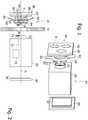
Fig. 1 shows a three-dimensional view of the apparatus;Fig. 2 shows a side view of the apparatus inFig. 1 .- In the figures, identical numbers indicate identical or conceptually similar parts, and the device is described as in use.
- An
electronic device 10, e.g. a temperature controller or timer, is mountable in an opening or hole H obtained on the wall W of a known electric panel or cabinet. The hole H has an axis indicated with X. - The
device 10 comprises a main box-shapedhollow body 20, for containing the control electronics, and a front part orfront panel 40. - The box-
shaped body 20 has square or rectangular cross-section, while thefront part 40 can have greater or smaller cross-section and/or different shape. - The box-
shaped body 20, which in the example is substantially a hollow parallelepiped housing, comprises at the center of a minor face a collar orcylindrical bushing 22 which surrounds an opening towards the inside. The diameter of thebushing 22 is e.g. smaller than the length of the relative side of the box-shaped body 20. - The back of the box-
shaped body 20 is preferably open (for inspection or maintenance or ventilation) and closable by awall 30 which has astep 32 complementary to the edges of said back. In known manner, thewall 30 can have openings to hold on the surface connection terminals. - The
front part 40 is detached from the box-shaped body 20 and couplable to it, and comprises a hollow, preferably flat and e.g. cuboid,shell 42 from whose center extends a bushing 44 having on the outer surface ascrewthread 46. The diameter of thebushing 44 is e.g. smaller than the length of the relative side of thehousing 42. - A
nut 50 is present and screwable on thethread 46, so as to push a(n) (optional) spring or plate 60 (or other elastic means) towards theshell 42. The spring orplate 60 is arranged around the bushing 44 (e.g. to this aim it is perforated at its center) and between theshell 42 and thenut 50. - Preferably, the spring or
plate 60 extends up to, or even beyond, the edges of theshell 42, and has a curved structure with the concavity towards theshell 42. - The
front part 40 constitutes the data output for the user. In particular, it can accommodate interfaces P like displays, LED, digital or analog numerical indicators.. - Preferably, the relative dimensions of the
bushings - The box-
shaped body 20 contains one or more electronic circuits andboards 70, e.g. a microprocessor that controls the functions of thedevice 10. Through one or more data and/or supply lines 72 aboard 70 can transfer data or supply power to aconnector 74, couplable with anotherconnector 76 present inside thebushing 44. Theconnector 76 is connected to one or more data and/orpower supply lines 78 to transfer data or to supply power to one ormore circuits 80 set within theshell 42, for example with the task of managing a display via aline 94 and/or of reading a keypad or interface P. - To mount the
apparatus 10 on the wall W, the wall W is perforated creating the opening to create a hole H corresponding to the diameter of the bushing 44 (e.g. 22 mm, the most common standard). Then thebushing 44 is inserted along the X axis in such hole H, and thenut 50 is screwed on thethread 46, up to tighten thefront part 40 to the wall W. - The
spring 60 also ensures the mounting in a square or differently-shaped hole H, or in a hole H with a size bigger than thebushing 44. - Then the
bushing 22 is inserted, along the X axis, on or into the bushing 44 (it depends on the relative sizes), accomplishing the electrical connection of theconnectors board 70 can communicate and/or power-supply acircuit 80. Once the connection is completed, the electrical continuity between theboard 70 and thecircuit 80 is reconstituted, therefore they can now work in cooperation. - It is advantageous, especially when on the
lines 72, 76 a lot of data must pass or to avoid a high number of conductors, that there be at most 2 or 3 conductors and that the transmission occur by modulation or other multiplexing technique (e.g. a serial transmission). - A big advantage of the above is that the
entire apparatus 10, and many similar samples, can be mounted on the wall W, which can be bored only with a circular opening (easy to do), even more advantageously with a circular opening of standard diameter, such e.g. 22 mm. Therefore one can use only one tool good for boring all the panel and for each apparatus. - The described housing is open to many variants.
- E.g. the
nut 50 and thethread 46 can be located on thebushing 22. - Or the
bushings body 20 and thepart 40 can joint into one another or connect to each other so as to clamp directly against the wall W, forming e.g. an adjustable-clamp structure.
Claims (9)
- Housing (10) of electronic apparatus mountable on a wall (W) of an electric panel or cabinet,
the housing comprising two parts:(i) a front portion (40) comprising a hollow, cuboid shell (42) for containing electronic components, and(ii) a box-shaped, hollow main body (20) comprising a shell (20) for containing electronic components,which parts are separated and configured to be able to connect to one another being, when connected, on opposite sides of the panel or cabinet,
wherein the front portion is configured as an interface for data output with a display and/or indicators, while
inside the main body there is the electronics that manages the device,
characterized in that
the two parts each comprise a connecting portion (44, 22), wherein each connecting portion projects cantilevered from its own shell and can be inserted into an opening (H) of the wall (W) to reach and connect with the other portion. - Housing according to claim 1, wherein the two parts are configured so that upon connecting they can tighten the panel or cabinet on opposite sides thereof.
- Housing according to claim 1 or 2, wherein the connecting portion of a part is insertable in complementary manner into the connection portion of the other part.
- Housing according to claim 3 or 1, wherein the connecting portions have a circular cross-section, preferably of a diameter of about 22 mm.
- Housing according to claim 3 or 4 or 1, wherein on the connecting portion of a part there is mounted a fastening element (50) adapted to lock that same part against the wall of the panel or cabinet.
- Housing according to claim 5, wherein the fastening element is screwable onto a thread (46) present on the portion.
- Housing according to claim 6 or 5, wherein between the two parts there is mounted or present an element (60) for support on the wall of the panel or cabinet, where the element for support has a radial dimension greater than that of the two parts.
- Housing according to claim 7, wherein the element (60) for support is an elastic element and is slidably mounted on a said portion, so that the fastening element can push it toward the shell from which that portion extends.
- Housing according to any one of claims 2 to 8, wherein each portion comprises an electrical connector (74, 76) adapted to electrically connect with the connector of the other portion when the portions are coupled.
Applications Claiming Priority (1)
| Application Number | Priority Date | Filing Date | Title |
|---|---|---|---|
| ITTV20140044 | 2014-03-25 |
Publications (2)
| Publication Number | Publication Date |
|---|---|
| EP2925101A1 EP2925101A1 (en) | 2015-09-30 |
| EP2925101B1true EP2925101B1 (en) | 2020-02-19 |
Family
ID=50877609
Family Applications (1)
| Application Number | Title | Priority Date | Filing Date |
|---|---|---|---|
| EP15159666.5AActiveEP2925101B1 (en) | 2014-03-25 | 2015-03-18 | Housing for an electrical or electronic apparatus |
Country Status (2)
| Country | Link |
|---|---|
| US (1) | US9380725B2 (en) |
| EP (1) | EP2925101B1 (en) |
Families Citing this family (1)
| Publication number | Priority date | Publication date | Assignee | Title |
|---|---|---|---|---|
| CN210202240U (en)* | 2019-05-27 | 2020-03-27 | 佳能企业股份有限公司 | Electronic device |
Citations (1)
| Publication number | Priority date | Publication date | Assignee | Title |
|---|---|---|---|---|
| US20090059001A1 (en)* | 2007-08-27 | 2009-03-05 | Chuan Wang | Remote-control door viewer surveillance system |
Family Cites Families (6)
| Publication number | Priority date | Publication date | Assignee | Title |
|---|---|---|---|---|
| US4066838A (en)* | 1976-04-30 | 1978-01-03 | Izumi Denki Corporation | Apparatus for detachably mounting electrical assembly units to supporting panels |
| US4273957A (en)* | 1979-06-06 | 1981-06-16 | Kolling Jr William J | Telecommunications access apparatus |
| ATE11980T1 (en)* | 1981-09-15 | 1985-03-15 | Square D Starkstrom Gmbh | DEVICE FOR ATTACHING AN ELECTRICAL DEVICE, IN PARTICULAR A CAM SWITCH, TO A MOUNTING PLATE. |
| SE500192C2 (en)* | 1993-04-20 | 1994-05-02 | Lars Gustafson | Signal indicator device |
| ES2123431B1 (en)* | 1996-10-14 | 1999-09-16 | Sistel Sa | IMPROVEMENTS INTRODUCED IN MEASURING OR CONTROL INSTRUMENTS. |
| US7881075B2 (en)* | 2007-05-22 | 2011-02-01 | Square D Company | Apparatus and methods for mounting and retaining power monitoring systems |
- 2015
- 2015-03-15USUS14/658,193patent/US9380725B2/enactiveActive
- 2015-03-18EPEP15159666.5Apatent/EP2925101B1/enactiveActive
Patent Citations (1)
| Publication number | Priority date | Publication date | Assignee | Title |
|---|---|---|---|---|
| US20090059001A1 (en)* | 2007-08-27 | 2009-03-05 | Chuan Wang | Remote-control door viewer surveillance system |
Also Published As
| Publication number | Publication date |
|---|---|
| US20150282371A1 (en) | 2015-10-01 |
| EP2925101A1 (en) | 2015-09-30 |
| US9380725B2 (en) | 2016-06-28 |
Similar Documents
| Publication | Publication Date | Title |
|---|---|---|
| US9589461B1 (en) | Battery powered wall mounted remote control for ceiling fans and lights | |
| US20080093927A1 (en) | Modular power distribution unit system | |
| US8003899B2 (en) | Mounting for industrial instrumentation | |
| CN104802033B (en) | Fixed cable-free tool | |
| AU2015100773A4 (en) | Dual combined socket and wireless charging apparatus | |
| EP2925101B1 (en) | Housing for an electrical or electronic apparatus | |
| US11016451B2 (en) | Modular load control | |
| JP5217000B2 (en) | furniture | |
| JP2019145485A (en) | Module for sensor box for industrial automation and corresponding sensor box | |
| US7893370B2 (en) | Module front for a switchgear assembly module, switchgear assembly module and electrical switchgear assembly | |
| AU2015100149B4 (en) | Power Assembly | |
| US20100170713A1 (en) | Enclosure with tubular coupling for containing electronic components | |
| EP3089293B1 (en) | A universal electrical installation system | |
| WO2006052079A3 (en) | Remote monitor in electric home appliances | |
| JP4887490B2 (en) | Outlet device and rack formed using the same | |
| US20200191372A1 (en) | Connection device for a luminaire | |
| JP5804527B2 (en) | Power connection device | |
| US10111309B2 (en) | Lighting control console having a slide control | |
| JP2019074244A (en) | Heating cooker | |
| RU2615138C1 (en) | Relay protection and control device (versions) | |
| JP5970281B2 (en) | Slave station for automatic voltage regulator | |
| US20150350785A1 (en) | Improved Wireless Audio System | |
| JP2009207214A (en) | Structure of the enclosure | |
| EP2690751A2 (en) | Remote annunciator | |
| JP3211383U (en) | USB power supply device |
Legal Events
| Date | Code | Title | Description |
|---|---|---|---|
| PUAI | Public reference made under article 153(3) epc to a published international application that has entered the european phase | Free format text:ORIGINAL CODE: 0009012 | |
| AK | Designated contracting states | Kind code of ref document:A1 Designated state(s):AL AT BE BG CH CY CZ DE DK EE ES FI FR GB GR HR HU IE IS IT LI LT LU LV MC MK MT NL NO PL PT RO RS SE SI SK SM TR | |
| AX | Request for extension of the european patent | Extension state:BA ME | |
| 17P | Request for examination filed | Effective date:20160330 | |
| RBV | Designated contracting states (corrected) | Designated state(s):AL AT BE BG CH CY CZ DE DK EE ES FI FR GB GR HR HU IE IS IT LI LT LU LV MC MK MT NL NO PL PT RO RS SE SI SK SM TR | |
| STAA | Information on the status of an ep patent application or granted ep patent | Free format text:STATUS: EXAMINATION IS IN PROGRESS | |
| 17Q | First examination report despatched | Effective date:20170418 | |
| REG | Reference to a national code | Ref country code:DE Ref legal event code:R079 Ref document number:602015047152 Country of ref document:DE Free format text:PREVIOUS MAIN CLASS: H05K0005000000 Ipc:H05K0005020000 | |
| GRAP | Despatch of communication of intention to grant a patent | Free format text:ORIGINAL CODE: EPIDOSNIGR1 | |
| STAA | Information on the status of an ep patent application or granted ep patent | Free format text:STATUS: GRANT OF PATENT IS INTENDED | |
| RIC1 | Information provided on ipc code assigned before grant | Ipc:H02B 1/044 20060101ALI20190906BHEP Ipc:H05K 5/02 20060101AFI20190906BHEP Ipc:H05K 5/00 20060101ALI20190906BHEP | |
| INTG | Intention to grant announced | Effective date:20191001 | |
| RIN1 | Information on inventor provided before grant (corrected) | Inventor name:BROCCARDO, LIVIO | |
| GRAS | Grant fee paid | Free format text:ORIGINAL CODE: EPIDOSNIGR3 | |
| GRAA | (expected) grant | Free format text:ORIGINAL CODE: 0009210 | |
| STAA | Information on the status of an ep patent application or granted ep patent | Free format text:STATUS: THE PATENT HAS BEEN GRANTED | |
| AK | Designated contracting states | Kind code of ref document:B1 Designated state(s):AL AT BE BG CH CY CZ DE DK EE ES FI FR GB GR HR HU IE IS IT LI LT LU LV MC MK MT NL NO PL PT RO RS SE SI SK SM TR | |
| REG | Reference to a national code | Ref country code:CH Ref legal event code:EP | |
| REG | Reference to a national code | Ref country code:DE Ref legal event code:R096 Ref document number:602015047152 Country of ref document:DE | |
| REG | Reference to a national code | Ref country code:AT Ref legal event code:REF Ref document number:1236485 Country of ref document:AT Kind code of ref document:T Effective date:20200315 | |
| REG | Reference to a national code | Ref country code:IE Ref legal event code:FG4D | |
| REG | Reference to a national code | Ref country code:NL Ref legal event code:MP Effective date:20200219 | |
| PG25 | Lapsed in a contracting state [announced via postgrant information from national office to epo] | Ref country code:RS Free format text:LAPSE BECAUSE OF FAILURE TO SUBMIT A TRANSLATION OF THE DESCRIPTION OR TO PAY THE FEE WITHIN THE PRESCRIBED TIME-LIMIT Effective date:20200219 Ref country code:FI Free format text:LAPSE BECAUSE OF FAILURE TO SUBMIT A TRANSLATION OF THE DESCRIPTION OR TO PAY THE FEE WITHIN THE PRESCRIBED TIME-LIMIT Effective date:20200219 Ref country code:NO Free format text:LAPSE BECAUSE OF FAILURE TO SUBMIT A TRANSLATION OF THE DESCRIPTION OR TO PAY THE FEE WITHIN THE PRESCRIBED TIME-LIMIT Effective date:20200519 | |
| REG | Reference to a national code | Ref country code:LT Ref legal event code:MG4D | |
| PG25 | Lapsed in a contracting state [announced via postgrant information from national office to epo] | Ref country code:BG Free format text:LAPSE BECAUSE OF FAILURE TO SUBMIT A TRANSLATION OF THE DESCRIPTION OR TO PAY THE FEE WITHIN THE PRESCRIBED TIME-LIMIT Effective date:20200519 Ref country code:GR Free format text:LAPSE BECAUSE OF FAILURE TO SUBMIT A TRANSLATION OF THE DESCRIPTION OR TO PAY THE FEE WITHIN THE PRESCRIBED TIME-LIMIT Effective date:20200520 Ref country code:HR Free format text:LAPSE BECAUSE OF FAILURE TO SUBMIT A TRANSLATION OF THE DESCRIPTION OR TO PAY THE FEE WITHIN THE PRESCRIBED TIME-LIMIT Effective date:20200219 Ref country code:LV Free format text:LAPSE BECAUSE OF FAILURE TO SUBMIT A TRANSLATION OF THE DESCRIPTION OR TO PAY THE FEE WITHIN THE PRESCRIBED TIME-LIMIT Effective date:20200219 Ref country code:IS Free format text:LAPSE BECAUSE OF FAILURE TO SUBMIT A TRANSLATION OF THE DESCRIPTION OR TO PAY THE FEE WITHIN THE PRESCRIBED TIME-LIMIT Effective date:20200619 Ref country code:SE Free format text:LAPSE BECAUSE OF FAILURE TO SUBMIT A TRANSLATION OF THE DESCRIPTION OR TO PAY THE FEE WITHIN THE PRESCRIBED TIME-LIMIT Effective date:20200219 | |
| PG25 | Lapsed in a contracting state [announced via postgrant information from national office to epo] | Ref country code:NL Free format text:LAPSE BECAUSE OF FAILURE TO SUBMIT A TRANSLATION OF THE DESCRIPTION OR TO PAY THE FEE WITHIN THE PRESCRIBED TIME-LIMIT Effective date:20200219 | |
| PG25 | Lapsed in a contracting state [announced via postgrant information from national office to epo] | Ref country code:DK Free format text:LAPSE BECAUSE OF FAILURE TO SUBMIT A TRANSLATION OF THE DESCRIPTION OR TO PAY THE FEE WITHIN THE PRESCRIBED TIME-LIMIT Effective date:20200219 Ref country code:ES Free format text:LAPSE BECAUSE OF FAILURE TO SUBMIT A TRANSLATION OF THE DESCRIPTION OR TO PAY THE FEE WITHIN THE PRESCRIBED TIME-LIMIT Effective date:20200219 Ref country code:SM Free format text:LAPSE BECAUSE OF FAILURE TO SUBMIT A TRANSLATION OF THE DESCRIPTION OR TO PAY THE FEE WITHIN THE PRESCRIBED TIME-LIMIT Effective date:20200219 Ref country code:EE Free format text:LAPSE BECAUSE OF FAILURE TO SUBMIT A TRANSLATION OF THE DESCRIPTION OR TO PAY THE FEE WITHIN THE PRESCRIBED TIME-LIMIT Effective date:20200219 Ref country code:RO Free format text:LAPSE BECAUSE OF FAILURE TO SUBMIT A TRANSLATION OF THE DESCRIPTION OR TO PAY THE FEE WITHIN THE PRESCRIBED TIME-LIMIT Effective date:20200219 Ref country code:PT Free format text:LAPSE BECAUSE OF FAILURE TO SUBMIT A TRANSLATION OF THE DESCRIPTION OR TO PAY THE FEE WITHIN THE PRESCRIBED TIME-LIMIT Effective date:20200712 Ref country code:SK Free format text:LAPSE BECAUSE OF FAILURE TO SUBMIT A TRANSLATION OF THE DESCRIPTION OR TO PAY THE FEE WITHIN THE PRESCRIBED TIME-LIMIT Effective date:20200219 Ref country code:CZ Free format text:LAPSE BECAUSE OF FAILURE TO SUBMIT A TRANSLATION OF THE DESCRIPTION OR TO PAY THE FEE WITHIN THE PRESCRIBED TIME-LIMIT Effective date:20200219 Ref country code:LT Free format text:LAPSE BECAUSE OF FAILURE TO SUBMIT A TRANSLATION OF THE DESCRIPTION OR TO PAY THE FEE WITHIN THE PRESCRIBED TIME-LIMIT Effective date:20200219 | |
| REG | Reference to a national code | Ref country code:CH Ref legal event code:PL | |
| REG | Reference to a national code | Ref country code:AT Ref legal event code:MK05 Ref document number:1236485 Country of ref document:AT Kind code of ref document:T Effective date:20200219 | |
| REG | Reference to a national code | Ref country code:DE Ref legal event code:R097 Ref document number:602015047152 Country of ref document:DE | |
| PG25 | Lapsed in a contracting state [announced via postgrant information from national office to epo] | Ref country code:MC Free format text:LAPSE BECAUSE OF FAILURE TO SUBMIT A TRANSLATION OF THE DESCRIPTION OR TO PAY THE FEE WITHIN THE PRESCRIBED TIME-LIMIT Effective date:20200219 | |
| REG | Reference to a national code | Ref country code:BE Ref legal event code:MM Effective date:20200331 | |
| PLBE | No opposition filed within time limit | Free format text:ORIGINAL CODE: 0009261 | |
| STAA | Information on the status of an ep patent application or granted ep patent | Free format text:STATUS: NO OPPOSITION FILED WITHIN TIME LIMIT | |
| PG25 | Lapsed in a contracting state [announced via postgrant information from national office to epo] | Ref country code:LU Free format text:LAPSE BECAUSE OF NON-PAYMENT OF DUE FEES Effective date:20200318 | |
| 26N | No opposition filed | Effective date:20201120 | |
| PG25 | Lapsed in a contracting state [announced via postgrant information from national office to epo] | Ref country code:IT Free format text:LAPSE BECAUSE OF FAILURE TO SUBMIT A TRANSLATION OF THE DESCRIPTION OR TO PAY THE FEE WITHIN THE PRESCRIBED TIME-LIMIT Effective date:20200219 Ref country code:AT Free format text:LAPSE BECAUSE OF FAILURE TO SUBMIT A TRANSLATION OF THE DESCRIPTION OR TO PAY THE FEE WITHIN THE PRESCRIBED TIME-LIMIT Effective date:20200219 Ref country code:CH Free format text:LAPSE BECAUSE OF NON-PAYMENT OF DUE FEES Effective date:20200331 Ref country code:IE Free format text:LAPSE BECAUSE OF NON-PAYMENT OF DUE FEES Effective date:20200318 Ref country code:LI Free format text:LAPSE BECAUSE OF NON-PAYMENT OF DUE FEES Effective date:20200331 | |
| PG25 | Lapsed in a contracting state [announced via postgrant information from national office to epo] | Ref country code:PL Free format text:LAPSE BECAUSE OF FAILURE TO SUBMIT A TRANSLATION OF THE DESCRIPTION OR TO PAY THE FEE WITHIN THE PRESCRIBED TIME-LIMIT Effective date:20200219 Ref country code:BE Free format text:LAPSE BECAUSE OF NON-PAYMENT OF DUE FEES Effective date:20200331 Ref country code:SI Free format text:LAPSE BECAUSE OF FAILURE TO SUBMIT A TRANSLATION OF THE DESCRIPTION OR TO PAY THE FEE WITHIN THE PRESCRIBED TIME-LIMIT Effective date:20200219 | |
| GBPC | Gb: european patent ceased through non-payment of renewal fee | Effective date:20200519 | |
| PG25 | Lapsed in a contracting state [announced via postgrant information from national office to epo] | Ref country code:GB Free format text:LAPSE BECAUSE OF NON-PAYMENT OF DUE FEES Effective date:20200519 | |
| PG25 | Lapsed in a contracting state [announced via postgrant information from national office to epo] | Ref country code:TR Free format text:LAPSE BECAUSE OF FAILURE TO SUBMIT A TRANSLATION OF THE DESCRIPTION OR TO PAY THE FEE WITHIN THE PRESCRIBED TIME-LIMIT Effective date:20200219 Ref country code:MT Free format text:LAPSE BECAUSE OF FAILURE TO SUBMIT A TRANSLATION OF THE DESCRIPTION OR TO PAY THE FEE WITHIN THE PRESCRIBED TIME-LIMIT Effective date:20200219 Ref country code:CY Free format text:LAPSE BECAUSE OF FAILURE TO SUBMIT A TRANSLATION OF THE DESCRIPTION OR TO PAY THE FEE WITHIN THE PRESCRIBED TIME-LIMIT Effective date:20200219 | |
| PG25 | Lapsed in a contracting state [announced via postgrant information from national office to epo] | Ref country code:MK Free format text:LAPSE BECAUSE OF FAILURE TO SUBMIT A TRANSLATION OF THE DESCRIPTION OR TO PAY THE FEE WITHIN THE PRESCRIBED TIME-LIMIT Effective date:20200219 Ref country code:AL Free format text:LAPSE BECAUSE OF FAILURE TO SUBMIT A TRANSLATION OF THE DESCRIPTION OR TO PAY THE FEE WITHIN THE PRESCRIBED TIME-LIMIT Effective date:20200219 | |
| P01 | Opt-out of the competence of the unified patent court (upc) registered | Effective date:20230515 | |
| PGFP | Annual fee paid to national office [announced via postgrant information from national office to epo] | Ref country code:DE Payment date:20240327 Year of fee payment:10 | |
| PGFP | Annual fee paid to national office [announced via postgrant information from national office to epo] | Ref country code:FR Payment date:20240325 Year of fee payment:10 |