EP2923185B1 - Consumption meter housing with feed through for external communication equipment - Google Patents
Consumption meter housing with feed through for external communication equipmentDownload PDFInfo
- Publication number
- EP2923185B1 EP2923185B1EP13856461.2AEP13856461AEP2923185B1EP 2923185 B1EP2923185 B1EP 2923185B1EP 13856461 AEP13856461 AEP 13856461AEP 2923185 B1EP2923185 B1EP 2923185B1
- Authority
- EP
- European Patent Office
- Prior art keywords
- consumption meter
- housing
- conductive
- conductive path
- cover
- Prior art date
- Legal status (The legal status is an assumption and is not a legal conclusion. Google has not performed a legal analysis and makes no representation as to the accuracy of the status listed.)
- Active
Links
- 238000004891communicationMethods0.000titleclaimsdescription59
- 238000007789sealingMethods0.000claimsdescription36
- 239000000126substanceSubstances0.000claimsdescription6
- 238000001816coolingMethods0.000claimsdescription4
- 238000005240physical vapour depositionMethods0.000claimsdescription4
- XLYOFNOQVPJJNP-UHFFFAOYSA-NwaterSubstancesOXLYOFNOQVPJJNP-UHFFFAOYSA-N0.000claimsdescription4
- 238000005229chemical vapour depositionMethods0.000claimsdescription2
- 239000011521glassSubstances0.000claimsdescription2
- 238000007747platingMethods0.000claimsdescription2
- 239000000463materialSubstances0.000description7
- 229910052751metalInorganic materials0.000description6
- 239000002184metalSubstances0.000description6
- PXHVJJICTQNCMI-UHFFFAOYSA-NNickelChemical compound[Ni]PXHVJJICTQNCMI-UHFFFAOYSA-N0.000description4
- 230000005540biological transmissionEffects0.000description4
- 229910001369BrassInorganic materials0.000description2
- 239000004721Polyphenylene oxideSubstances0.000description2
- 239000010951brassSubstances0.000description2
- 239000004020conductorSubstances0.000description2
- 238000000151depositionMethods0.000description2
- 230000008021depositionEffects0.000description2
- 239000012530fluidSubstances0.000description2
- PCHJSUWPFVWCPO-UHFFFAOYSA-NgoldChemical compound[Au]PCHJSUWPFVWCPO-UHFFFAOYSA-N0.000description2
- 229910052737goldInorganic materials0.000description2
- 239000010931goldSubstances0.000description2
- 229910052759nickelInorganic materials0.000description2
- 229920000570polyetherPolymers0.000description2
- 230000001105regulatory effectEffects0.000description2
- 239000003566sealing materialSubstances0.000description2
- 125000001174sulfone groupChemical group0.000description2
- VYZAMTAEIAYCRO-UHFFFAOYSA-NChromiumChemical compound[Cr]VYZAMTAEIAYCRO-UHFFFAOYSA-N0.000description1
- RYGMFSIKBFXOCR-UHFFFAOYSA-NCopperChemical compound[Cu]RYGMFSIKBFXOCR-UHFFFAOYSA-N0.000description1
- 229920000265PolyparaphenylenePolymers0.000description1
- BQCADISMDOOEFD-UHFFFAOYSA-NSilverChemical compound[Ag]BQCADISMDOOEFD-UHFFFAOYSA-N0.000description1
- UCKMPCXJQFINFW-UHFFFAOYSA-NSulphideChemical compound[S-2]UCKMPCXJQFINFW-UHFFFAOYSA-N0.000description1
- RTAQQCXQSZGOHL-UHFFFAOYSA-NTitaniumChemical compound[Ti]RTAQQCXQSZGOHL-UHFFFAOYSA-N0.000description1
- 230000001070adhesive effectEffects0.000description1
- 229910045601alloyInorganic materials0.000description1
- 239000000956alloySubstances0.000description1
- 229910052782aluminiumInorganic materials0.000description1
- XAGFODPZIPBFFR-UHFFFAOYSA-NaluminiumChemical compound[Al]XAGFODPZIPBFFR-UHFFFAOYSA-N0.000description1
- 238000005266castingMethods0.000description1
- 238000005234chemical depositionMethods0.000description1
- 229910052804chromiumInorganic materials0.000description1
- 239000011651chromiumSubstances0.000description1
- 239000011248coating agentSubstances0.000description1
- 238000000576coating methodMethods0.000description1
- 229910052802copperInorganic materials0.000description1
- 239000010949copperSubstances0.000description1
- 238000001514detection methodMethods0.000description1
- 239000003651drinking waterSubstances0.000description1
- 235000020188drinking waterNutrition0.000description1
- 230000000694effectsEffects0.000description1
- 239000003292glueSubstances0.000description1
- 238000010438heat treatmentMethods0.000description1
- 238000005259measurementMethods0.000description1
- 229910001092metal group alloyInorganic materials0.000description1
- 238000000034methodMethods0.000description1
- 238000005289physical depositionMethods0.000description1
- 239000004417polycarbonateSubstances0.000description1
- 229920000515polycarbonatePolymers0.000description1
- -1polyphenylenePolymers0.000description1
- 230000001902propagating effectEffects0.000description1
- 238000009420retrofittingMethods0.000description1
- 229910052709silverInorganic materials0.000description1
- 239000004332silverSubstances0.000description1
- 229910000679solderInorganic materials0.000description1
- 239000010935stainless steelSubstances0.000description1
- 229910001220stainless steelInorganic materials0.000description1
- 230000003746surface roughnessEffects0.000description1
- 239000010936titaniumSubstances0.000description1
- 229910052719titaniumInorganic materials0.000description1
Images


Classifications
- G—PHYSICS
- G01—MEASURING; TESTING
- G01F—MEASURING VOLUME, VOLUME FLOW, MASS FLOW OR LIQUID LEVEL; METERING BY VOLUME
- G01F15/00—Details of, or accessories for, apparatus of groups G01F1/00 - G01F13/00 insofar as such details or appliances are not adapted to particular types of such apparatus
- G01F15/06—Indicating or recording devices
- G—PHYSICS
- G01—MEASURING; TESTING
- G01D—MEASURING NOT SPECIALLY ADAPTED FOR A SPECIFIC VARIABLE; ARRANGEMENTS FOR MEASURING TWO OR MORE VARIABLES NOT COVERED IN A SINGLE OTHER SUBCLASS; TARIFF METERING APPARATUS; MEASURING OR TESTING NOT OTHERWISE PROVIDED FOR
- G01D4/00—Tariff metering apparatus
- G01D4/02—Details
- G—PHYSICS
- G01—MEASURING; TESTING
- G01D—MEASURING NOT SPECIALLY ADAPTED FOR A SPECIFIC VARIABLE; ARRANGEMENTS FOR MEASURING TWO OR MORE VARIABLES NOT COVERED IN A SINGLE OTHER SUBCLASS; TARIFF METERING APPARATUS; MEASURING OR TESTING NOT OTHERWISE PROVIDED FOR
- G01D11/00—Component parts of measuring arrangements not specially adapted for a specific variable
- G01D11/24—Housings ; Casings for instruments
Definitions
- the inventionrelates to a consumption meter adapted for attachment of external communication equipment.
- Consumption meters for calculating a consumed quantity of water, heat, cooling, gas or the liketypically have a flow part with a through-going opening that forms a flow passage for a flow of the quantity to be measured and a compartment or housing with a cavity for housing electronic components of the meter.
- the housingserves to protect the electronic components, such as a measuring circuit for operating the meter, ultrasonic transducers for determining the flow in the flow passage, and additional electronic equipment, such as a calculation circuit for calculating the consumed quantity, a display for displaying a value representing the consumed quantity, a battery for powering the electronic components, a communication module, etc.
- the housingserves to protect the electronic components from exposure to the ambient conditions when the consumption meter is placed in wet or moist surroundings.
- a communication moduleis used for wireless transmission of the value or a signal representing the consumed quantity. It is of benefit that the signal can be transmitted a certain communication distance i.e. that the consumption meter has a certain communication range. This communication range should preferably be present during the lifetime of the consumption meter.
- the desire of protecting the electronic components from ambient exposure and the desire of a certain communication rangemay be in conflict with each other.
- One solution of protecting the electronic componentsis to use an internal antenna, which however may hamper the communication range.
- Another solution of ensuring a certain communication rangeis to use an external antenna, this may however either hamper the protection of the electronic components due to the presence of an electric feed through or require a costly solution to provide a housing which protects, and continues to protect, the electronics against exposure from ambient conditions.
- a consumption meter instrumentwhere a sealing material is used to join together a top and a base of the instrument.
- a sealed wire entry portis provided where a pair of insulated wires runs through the body of the sealing material.
- the instrumentfurther comprises a vent which is adapted to be closed after a gas has been either evacuated or introduced into the interior of the housing to reduce moisture within the housing before final sealing.
- a consumption meteris able to function for a long period under various ambient conditions. More specifically, it would be advantageous to achieve a consumption meter with improved communication capabilities which is resistant to operating under various ambient conditions. In particular, it would be advantageous to provide a consumption meter which is adapted for attachment of external communication equipment in a cost-efficient manner, which does not jeopardize the ability of the meter to operate under various ambient conditions.
- the inventionpreferably seeks to mitigate, alleviate or eliminate one or more of the above mentioned disadvantages singly or in any combination.
- the present inventionprovides a consumption meter for measuring consumption data of a supplied utility and with a conductive feed through for external communication equipment, the consumption meter comprising:
- a consumption meterwhich due to the provision of the conductive path is able to function for a long period under various ambient conditions even in a situation where external communication equipment is connected. It is advantageous that external equipment may be connected to internal equipment in a manner which does not further expose equipment inside the closed compartment to moist or other harmful substances from the ambient conditions in which the meter is placed.
- a single sealing meanswhich is provided in a single opening of the housing is also used as a sealing for the conductive path. In this manner, the housing is closed off and the compartment is protected from the ambient with only a few elements.
- An advantagemay be that deployment of external communication equipment can easily be provided, while still providing a controlled protection of the components inside the housing from the ambient conditions.
- External communication equipmentmay increase the transmission range and/or lower the use of power need for data transmission.
- the described solutionenables an easy addition of external communication equipment, e.g., for one or more consumption meters among a plurality of consumption meters, which are not able to transmit their values far enough under the given radio transmission conditions.
- the described solutionenables retrofitting the consumption meter with external communication equipment.
- the at least one conductive pathcomprises a terminal for connection of the external communication equipment on the outside part of the consumption meter.
- a surface of the conductive part on the outside of the consumption metermay be seen to be enough to serve as a terminal.
- the first and a second sections of the at least one conductive pathare pressed and held towards each other to form a conductive connection between the first and the second sections when the consumption meter is assembled.
- an end part of the first sectionis flexible and biased towards the second section when the meter is assembled.
- other meansmay be used for electrically connecting the two sections, such as by use of solder or a plug connection.
- the at least one conductive pathis provided, at least in part, by use of a chemical or physical deposition technique, e.g. Chemical or Physical Vapor Deposition, CVD or PVD, on the housing or on the cover.
- a chemical or physical deposition techniquee.g. Chemical or Physical Vapor Deposition, CVD or PVD
- Such path provided by such depositionis provided on both an inner and outer surface of the housing or of the cover.
- Such deposition, or any other conductive layer or member particularly suitable for use as described hereinmay end after or just after passing the sealing means.
- the terminalis possibly for a cable or an external antenna or may in itself be used as at least a part of an external antenna.
- Such type of pathcan be provided in a way where ambient conditions are not able to enter the compartment in the housing. This may be due to the limited thickness such path can be provided with and/or due to such path preventing ambient conditions from entering the compartment in the housing between a second surface of the path and the housing or between a second surface of the path and the cover.
- a CVD or PVD pathand possibly the limited thickness thereof, enables the sealing means between the housing and the cover, to prevent the ambient conditions from entering the cavity along other surfaces, such as the first surface, of the path.
- the sealing meansis the one already included between the cover and the housing for closing the single opening of the housing.
- only a single sealing means or elementis used.
- the at least one conductive pathat least in an area at the sealing means, includes a chemical or physical bonding between a second surface of the conductive path and the housing or the cover, so as to prevent ambient conditions, such as moist and/or air with a relative high humidity, from entering the housing between said second surface of the conductive path and the housing or cover.
- the external communication equipmentis at least partly formed in the cover or in the housing.
- the conductive pathcan additionally and advantageously be used to include cost efficient and effective external communication equipment in the consumption meter.
- Fig. 1is a perspective view of a consumption meter 102.
- the consumption metermay in embodiments be a consumption meter for charging a consumer a cost of an amount of a supplied utility. Such a consumption meter may also be referred to as a utility meter.
- the consumption metermay be an energy meter for metering an amount of energy consumed, a heat meter for district heating, a cooling meter for district cooling, a water meter for cold and/or hot water, e.g. distributed drinking water, or a gas meter.
- the consumption metermay be a legal meter, i.e. a meter which is subdued to regulatory demands. Such regulatory demands may be demands to the precision of the measurements.
- An ultrasonic flow meteris a transit time flow meter arranged to measure a flow rate of a fluid flowing in a flow part by use of the known operation principle for transit time flow meters, where ultrasonic signals are emitted at one transducer, see reference 311 in figure 3 , and received at the other transducer, and where the difference in time-of-arrival between oppositely propagating signals is measured and converted into a flow rate.
- the piezoelectric transducersare operated by a control circuit, which based on the involved signals generate a signal or value indicative of the flow rate of the fluid.
- the level of signal treatment of the control circuitmay vary from basic signal treatment, where processed signals are output to a further electronic unit for further signal processing, to a complete signal treatment resulting in the determination of the flow rate.
- Such further electronic unitmay be part of the consumption meter 102, or may be part of a separate calculator circuit (not shown) communicatively connected to the consumption meter.
- the illustrated consumption meter 102has a housing 104 closed by a cover 106.
- the housingis in a closed state, where the cover 106 is attached to the housing 104 using a cover holder 108.
- the cover holder 108may be an integrated part of the cover or an integrated part of the housing.
- the cover, the housing and the cover holderare separate parts.
- the housingis provided in a generally, nonconductive polymeric material such as selected from, but is not limited to, the group consisting of polyphenylene sulphide (PPS), polyether sulphone (PES) and Polyether Sulphone (PSU).
- PPSpolyphenylene sulphide
- PESpolyether sulphone
- PSUPolyether Sulphone
- the cover 106 or at least an area thereofis transparent.
- the covermay be provided by a polymeric material such as polycarbonate, possibly with a coating, but in the embodiments herein it is provided by glass.
- the illustrated consumption meteris a kind which has a flow part 110 with an inlet 109 and an outlet 111 that form a flow passage for a flow of the consumed quantity to be measured.
- the housing 104 of the consumption meteris integrated with the flow part 110.
- the flow part and the housingare not formed as one integrated part, but may be separate units or parts attached to each other.
- a separate flow partmay also be provided in or comprise a polymeric material, but may alternatively comprise or be provided in metal, such as a metal alloy such as brass, red brass, stainless steel, or other suitable casting alloys.
- the conductive pathcould be provided with a non-conductive attachment layer towards such metal housing or the metal housing could comprise a surface towards the conductive path which insulates the conductive path from the metal housing.
- a polymeric housingis used in the embodiments herein.
- the housingserves to protect electronic components, such as a measuring circuit that controls components of the meter for determining the consumed quantity, such as the flow in the flow passage, from conditions outside the housing.
- the electronic components for an ultrasonic flow metertypically comprises ultrasonic transducer(s), as well as any additional electronic equipment, such as a calculation circuit for calculating the consumed quantity, a display for displaying a value representing the consumed quantity, a battery for powering the electronic components and/or or a communication module, e.g. for transmitting a value representing the consumed quantity wirelessly using radio frequencies.
- the housingmay additionally include at least one of: ultrasonic transducer(s), a calculation circuit for calculating the consumed quantity, a display for displaying the value representing the consumed quantity and a battery for powering the electronic components.
- Fig. 2is the perspective cut through of an embodiment of a consumption meter, where electronics etc. inside the housing of the consumption meter can be seen.
- a circuit board 206with a display 208 and a communication module 204.
- the housingalso includes a battery and a calculation circuit, but such electronic equipment is not illustrated in the figure. It can be seen from the cut through that the housing 104 is closed by the cover 106 and sealed from outside conditions to form a closed cavity by the sealing means 210.
- the sealing meansis an O-ring, i.e. an endless, or unbroken, sealing element 210.
- the sealing meansis provided on a rim of the cavity and arranged for sealed connection with the cover 106, so that the cover 106 and the cavity of the housing 104 define a sealed enclosure, preferably with only a single sealing area and/or a single sealing means.
- the sealing elementis provided in a material to allow it to provide the sealing effect between the housing and the cover, also when minor irregularities and/or surface roughness are comprised in the surfaces and when at least one of the surfaces to seal between is provided with a conductive path as described herein.
- the sealing elementis a flexible rubber ring-shaped element (O-ring), but may also be provided by other means such as by sealing glue or by sealing paste.
- the cover holder 108 and the housing 104are provided with treads 212 so as to close and seal the housing by rotation of the cover holder 108 relatively to the housing and so as to use the treads to press the cover towards the sealing means 210 and hereby form the closed compartment with the closed cavity in the housing 104.
- the manner and means for providing this closuremay vary from this in several ways, such as not to use treads and/or rotation, but e.g. to press the cover 106 towards the opening of the housing 104 and when a certain pressure and/or position is achieved, the two parts lock to each other in a closed state, e.g. using a snap lock connection.
- At least one conductive path 202is provided from the communication module 204 via an inner surface 214 of the housing 104.
- a further conductive path 203can be provided.
- This further conductive pathis illustrated also to be a conductive feed from the communication module 204, and may e.g., be a conductive feed for a ground part of a conductive feed for an antenna for the communication module.
- Other conductive pathsmay be provided, such as paths for connection of external power to the electronics and/or for charging the battery, if present.
- the conductive pathmay be a conductive micro strip, a conductive film, a printed conductive layer or thin conductive plating.
- Fig. 3is a side view of the consumption meter illustrated in figure 2 .
- the cover holder illustrated in figure 2is for simplicity and/or because it is not needed, not shown in figure 3 .
- the figureillustrates the conductive path 202.
- the conductive pathis shown separate and enlarged at the bottom of the figure.
- the figuremoreover shows the section A-A which is a perpendicular cut through the housing wall 104.
- the conductive pathis a conductive feed from the communication module 204, with a first section 302 transferring the conductive feed from the communication module to a second section 304 comprised on the inner surface 214 of the housing 108.
- the first and second sectionsare pressed and held towards each other, so as to form a conductive connection between them in the shown assembled state of the consumption meter and thus closed and sealed state of the housing 104.
- the conductive path 202passes and touches the sealing means 210 in an area where the sealing means 210 defines a border and provides a seal between outside ambient conditions and an inside of the closed compartment.
- a section of the conductive path after the bordercan be referred to as a third section 306 of the conductive path 202, which third section 306 is provided in the ambient conditions. It is illustrated that the conductive path 202 clings round an edge of the housing 104 at the opening of the housing and in this manner reaches the ambient conditions and enables conductive access to the path outside the closed housing.
- the conductive path 202has a first surface 308 facing, or towards, the sealing means 210 and a second surface 310 facing, or attached to, the housing. At least in an area at the sealing means 210, thus at least in the border or sealing area, the conductive path 202 includes a chemical or physical bonding between the second surface 310 of the conductive path and the housing, so as to prevent ambient conditions, such as moist, from entering the cavity in the housing 104 between said second surface 310 of the conductive path and the housing.
- the sealing means 210provides this protection between the first surface 308 and the sealing means 210.
- the at least one conductive path 202is provided on the inner surface 214 and an outer surface of the housing 104. On the inner surface the second section 304 is provided and on the outer surface the third section 306 is provided.
- the first section 302 of the conductive path 202comprises a flexible, spring like member to be biased towards the second section 304 of the path.
- the spring like membersuch as a spring connector or flexible connector, can be surface mounted on the circuit board 206.
- the shown embodimentis an ultrasonic flow meter
- two ultrasonic transducers 311are illustrated and included in the housing 104.
- Fig. 4is a side view of another embodiment of the consumption meter.
- the first section 402 of the conductive path 408includes a flexible member which is adapted to, when the consumption meter is assembled, be pressed and held towards a second section 404 of the conductive path 408, which second section 404 is provided on an inner surface 410 of the cover 106. It can be seen that the conductive path 408 clings round an edge of the cover 106 close to the sealing means 210.
- Fig. 3 and 4have a conductive path on both an inner and an outside surface of the housing and the cover, respectively. It is possible that both the housing and the cover are provided with one or more sections of the conductive path, e.g. on both inner and outer surface of the housing and on an outer surface of the cover.
- the conductive pathmay comprise a deposited layer.
- the conductive pathmay comprise an attachment layer and a conductive layer.
- the at least one conductive pathcomprises a layer with a thickness of less than 0.1 mm.
- a total thickness of the pathis less than 0.25 mm or even also less than 0.1 mm.
- the attachment layermay be electrically isolating or conductive in dependence on, amongst other aspects, of the adhesive properties of the material of the housing.
- the attachment layermay be provided in or include materials such as: titanium, chromium or aluminum.
- the conductive path or a conductive layer of the conductive pathmay be provided in or include one or more materials such as: gold, silver, copper, nickel, e.g. gold plated nickel.
- Fig. 5is a perspective view of an antenna configuration 502 provided on the outer surface of the cover 106.
- the conductive path 408 for the conductive feed throughis shown with a dashed line from the communication module 204 inside the closed housing 104, via the inside surface of the cover, passing the opening of the housing 104, round an edge of the cover 106 and onto an outer surface of the cover.
- the conductive path 408then forms some shape suited as a part of an external antenna on the cover 106.
- the external antennamay be protected with a thin protection layer on top of the conductive path on the outside surface of the cover.
- the external antennamay be one part of a dipole antenna.
- the external antennamay also be a dipole antenna where two separate conductive paths are provided from the compartment. The two paths may then continue on the external side of the cover and form a dipole external antenna.
- Fig. 6is a side view of a first terminal configuration with an external antenna 604.
- the external antennais operably connected to one or more conductive paths 202 and attached to the consumption meter 102 by attachment means 606.
- the antenna 604is connected to the third section of the conductive path 202 via an access point or through going hole 602 in the cover holder 108.
- an alternative element encircling the consumption meter and being operably pressed towards the conductive path at the outside of the consumption meter 102may be used as an antenna and/or comprise a terminal or a socket for a terminal.
- the antenna or aerialmay be attached to or incorporated in the consumption meter at delivery or may be attached to and/or operably switched to be connected to the communication module, afterwards, e.g. upon detection of no or pour signals from the consumption meter 102.
- the conductive surface of the conductive pathmay serve as a terminal for connection of a cable, e.g. by providing a socket at least partly formed in the cover holder or in the housing.
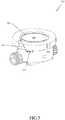
- Fig. 7is a side view of a second terminal configuration with an antenna 704.
- the external antenna 704is operably connected to one or more conductive paths 408 and attached to the consumption meter 102 by attachment means 706.
- the antenna 704is connected a section of the conductive path 408 via an access point or through going hole 702 in the cover holder 108.
- Fig. 8illustrates an embodiment of a consumption meter where the meter is installed in a so-called meter pit 80 where the meter is installed in-line with an underground pipe 81 and connected to a pit lid transmitter 84 installed in a pit lid 85.
- the meteris as illustrated in Fig. 4 , where the conductive path is provided on the surface of the cover 106.
- the conductive pathmay also be provided as illustrated in Fig. 3 , where the conductive path is provided on the surface of the housing 108.
- the conductive pathis connected to a plug 82 which via a wire 83 connects the communication module of the meter to a pit lid transmitter 84.
- the pit lid transmittermay be either a passive antenna device, i.e. an external antenna placed in the pit lid 85, or an active antenna device, e.g. to boost or otherwise modify the signal to or from the communication module, or other form of communication equipment.
- the plug connector 82may either be formed together with the cover 106 (or housing 108) or it may be attached as a separate element which facilitates contact between a connecting plug to be inserted in the plug 82 and the conductive path.
- Fig. 9illustrates an enlarged schematic top view of the plug 82 of Fig. 8 .
- the figureillustrates the plug 82 which has been attached to the cover 106 by use of screws 90.
- the plugcomprises a number of sockets 91, or female connectors, capable of receiving a plug with male connectors.
- the plug 82is attached over a number of terminals (not shown) of the conductor path 404 (second section).
- the conductive pathis a path with two or more conductive sub-paths 93. Here three sub-paths are shown.
- the conductive pathis thus a collection of paths for providing a number of conductors along the path. In this manner a communication line may be provided to and/or from the communication module to external communication equipment.
- the external communication equipmentis thus the plug 82, the cable 83 and the transmitter 84.
- the external communication equipmentmay be any element which facilitates connection of further communication equipment to the consumption meter, such as equipment ranging from a plug or part of a plug to more advanced equipment.
- the communication modulecan in embodiments be pre-adjusted for one type of external communication equipment.
- one or more electronic components in the housingmay be able to detect the presence of one or more type(s) of external communication equipment and where the communication module is able to switch between adjustments in accordance with the detected external communication equipment.
- the consumption metercan be equipped with one or more electronic components in the housing which is/are able to detect the presence of one or more type(s) of external antennas.
- the communication module, or another piece of electronic equipment in the housingis then provided for and able to switch between adjustments in accordance with the detected external antenna.
- the external antennamay be relatively small, e.g. shorter than 100 mm, or a relatively large external antenna, e.g. 100-250 mm long and connected to an outside part of the consumption meter subject to ambient conditions and where access to the conductive feed through and the conductive part can be provided.
Landscapes
- Physics & Mathematics (AREA)
- General Physics & Mathematics (AREA)
- Fluid Mechanics (AREA)
- Arrangements For Transmission Of Measured Signals (AREA)
- Measuring Volume Flow (AREA)
- Connector Housings Or Holding Contact Members (AREA)
Description
- The invention relates to a consumption meter adapted for attachment of external communication equipment.
- Consumption meters for calculating a consumed quantity of water, heat, cooling, gas or the like, typically have a flow part with a through-going opening that forms a flow passage for a flow of the quantity to be measured and a compartment or housing with a cavity for housing electronic components of the meter. The housing serves to protect the electronic components, such as a measuring circuit for operating the meter, ultrasonic transducers for determining the flow in the flow passage, and additional electronic equipment, such as a calculation circuit for calculating the consumed quantity, a display for displaying a value representing the consumed quantity, a battery for powering the electronic components, a communication module, etc. In particular, the housing serves to protect the electronic components from exposure to the ambient conditions when the consumption meter is placed in wet or moist surroundings.
- In a system with automatic meter reading for reporting the consumed quantity, a communication module is used for wireless transmission of the value or a signal representing the consumed quantity. It is of benefit that the signal can be transmitted a certain communication distance i.e. that the consumption meter has a certain communication range. This communication range should preferably be present during the lifetime of the consumption meter.
- The desire of protecting the electronic components from ambient exposure and the desire of a certain communication range may be in conflict with each other. One solution of protecting the electronic components is to use an internal antenna, which however may hamper the communication range. Another solution of ensuring a certain communication range is to use an external antenna, this may however either hamper the protection of the electronic components due to the presence of an electric feed through or require a costly solution to provide a housing which protects, and continues to protect, the electronics against exposure from ambient conditions.
- In
US 5,734,103 a consumption meter instrument is disclosed where a sealing material is used to join together a top and a base of the instrument. A sealed wire entry port is provided where a pair of insulated wires runs through the body of the sealing material. The instrument further comprises a vent which is adapted to be closed after a gas has been either evacuated or introduced into the interior of the housing to reduce moisture within the housing before final sealing. - It would be advantageous to achieve a solution where a consumption meter is able to function for a long period under various ambient conditions. More specifically, it would be advantageous to achieve a consumption meter with improved communication capabilities which is resistant to operating under various ambient conditions. In particular, it would be advantageous to provide a consumption meter which is adapted for attachment of external communication equipment in a cost-efficient manner, which does not jeopardize the ability of the meter to operate under various ambient conditions.
- In general, the invention preferably seeks to mitigate, alleviate or eliminate one or more of the above mentioned disadvantages singly or in any combination. In particular, it may be seen as an object of the present invention to provide a solution that solves the above mentioned problems, or other problems, of the prior art.
- The present invention provides a consumption meter for measuring consumption data of a supplied utility and with a conductive feed through for external communication equipment, the consumption meter comprising:
- a housing with an opening, where the housing forms a closed compartment when the opening of the housing is closed with a cover,
- a sealing means provided in the opening of the housing to provide a sealed closed compartment when the opening of the housing is closed with the cover, and
- a communication module provided in the closed compartment,
- Thus a consumption meter is provided which due to the provision of the conductive path is able to function for a long period under various ambient conditions even in a situation where external communication equipment is connected. It is advantageous that external equipment may be connected to internal equipment in a manner which does not further expose equipment inside the closed compartment to moist or other harmful substances from the ambient conditions in which the meter is placed.
- Advantageously, a single sealing means which is provided in a single opening of the housing is also used as a sealing for the conductive path. In this manner, the housing is closed off and the compartment is protected from the ambient with only a few elements.
- An advantage may be that deployment of external communication equipment can easily be provided, while still providing a controlled protection of the components inside the housing from the ambient conditions. External communication equipment may increase the transmission range and/or lower the use of power need for data transmission.
- Still further, a possible advantage is that the described solution enables an easy addition of external communication equipment, e.g., for one or more consumption meters among a plurality of consumption meters, which are not able to transmit their values far enough under the given radio transmission conditions. Thus the described solution enables retrofitting the consumption meter with external communication equipment.
- In a general embodiment, the at least one conductive path comprises a terminal for connection of the external communication equipment on the outside part of the consumption meter. A surface of the conductive part on the outside of the consumption meter may be seen to be enough to serve as a terminal.
- Advantageously, the first and a second sections of the at least one conductive path are pressed and held towards each other to form a conductive connection between the first and the second sections when the consumption meter is assembled. In an embodiment, an end part of the first section is flexible and biased towards the second section when the meter is assembled. In general however, other means may be used for electrically connecting the two sections, such as by use of solder or a plug connection.
- In embodiments, the at least one conductive path is provided, at least in part, by use of a chemical or physical deposition technique, e.g. Chemical or Physical Vapor Deposition, CVD or PVD, on the housing or on the cover. In embodiments of the invention such path provided by such deposition is provided on both an inner and outer surface of the housing or of the cover. Such deposition, or any other conductive layer or member particularly suitable for use as described herein, may end after or just after passing the sealing means. In such a way it is possible to connect to the at least one conductive path at a position in the ambient conditions and hereby, e.g., provide a terminal in the ambient conditions. The terminal is possibly for a cable or an external antenna or may in itself be used as at least a part of an external antenna.
- Such type of path can be provided in a way where ambient conditions are not able to enter the compartment in the housing. This may be due to the limited thickness such path can be provided with and/or due to such path preventing ambient conditions from entering the compartment in the housing between a second surface of the path and the housing or between a second surface of the path and the cover.
- Further, a CVD or PVD path, and possibly the limited thickness thereof, enables the sealing means between the housing and the cover, to prevent the ambient conditions from entering the cavity along other surfaces, such as the first surface, of the path. Preferably, the sealing means is the one already included between the cover and the housing for closing the single opening of the housing. Preferably, only a single sealing means or element is used.
- Thus, in accordance with embodiments of the invention, the at least one conductive path, at least in an area at the sealing means, includes a chemical or physical bonding between a second surface of the conductive path and the housing or the cover, so as to prevent ambient conditions, such as moist and/or air with a relative high humidity, from entering the housing between said second surface of the conductive path and the housing or cover.
- Further advantages of the solution may arise when the external communication equipment is at least partly formed in the cover or in the housing. Hereby the conductive path can additionally and advantageously be used to include cost efficient and effective external communication equipment in the consumption meter.
- Further advantageous embodiments of the solution are disclosed in the description of the embodiments. In general the various aspects or embodiments of the invention may be combined and coupled in any way possible within the scope of the invention. These and other aspects, features and/or advantages of the invention will be apparent from and elucidated with reference to the embodiments described hereinafter.
- Embodiments of the invention will be described, by way of example only, with reference to the drawings, in which
Fig. 1 is a perspective view of a consumption meter,Fig. 2 is the perspective cut through of a first embodiment of the consumption meter, where electronics etc. inside the housing of the consumption meter can be seen,Fig. 3 is a side view of one embodiment of the consumption meter,Fig. 4 is a side view of another embodiment of the consumption meter,Fig. 5 is a perspective view of an antenna configuration provided on the cover,Fig. 6 is a side view of a first terminal configuration with an antenna,Fig. 7 is a side view of a second terminal configuration with an antenna,Fig. 8 illustrates an embodiment of a consumption meter where the meter is installed in a meter pit, andFig. 9 illustrates an enlarged schematic top view of the plug ofFig. 8 .Fig. 1 is a perspective view of aconsumption meter 102. The consumption meter may in embodiments be a consumption meter for charging a consumer a cost of an amount of a supplied utility. Such a consumption meter may also be referred to as a utility meter. The consumption meter may be an energy meter for metering an amount of energy consumed, a heat meter for district heating, a cooling meter for district cooling, a water meter for cold and/or hot water, e.g. distributed drinking water, or a gas meter. The consumption meter may be a legal meter, i.e. a meter which is subdued to regulatory demands. Such regulatory demands may be demands to the precision of the measurements.- An ultrasonic flow meter, as embodied herein, is a transit time flow meter arranged to measure a flow rate of a fluid flowing in a flow part by use of the known operation principle for transit time flow meters, where ultrasonic signals are emitted at one transducer, see
reference 311 infigure 3 , and received at the other transducer, and where the difference in time-of-arrival between oppositely propagating signals is measured and converted into a flow rate. The piezoelectric transducers are operated by a control circuit, which based on the involved signals generate a signal or value indicative of the flow rate of the fluid. The level of signal treatment of the control circuit may vary from basic signal treatment, where processed signals are output to a further electronic unit for further signal processing, to a complete signal treatment resulting in the determination of the flow rate. Such further electronic unit may be part of theconsumption meter 102, or may be part of a separate calculator circuit (not shown) communicatively connected to the consumption meter. - The illustrated
consumption meter 102 has ahousing 104 closed by acover 106. In the shown embodiment the housing is in a closed state, where thecover 106 is attached to thehousing 104 using acover holder 108. Thecover holder 108 may be an integrated part of the cover or an integrated part of the housing. In the shown embodiment the cover, the housing and the cover holder are separate parts. The housing is provided in a generally, nonconductive polymeric material such as selected from, but is not limited to, the group consisting of polyphenylene sulphide (PPS), polyether sulphone (PES) and Polyether Sulphone (PSU). Thecover 106 or at least an area thereof is transparent. The cover may be provided by a polymeric material such as polycarbonate, possibly with a coating, but in the embodiments herein it is provided by glass. - The illustrated consumption meter is a kind which has a
flow part 110 with aninlet 109 and anoutlet 111 that form a flow passage for a flow of the consumed quantity to be measured. As illustrated, thehousing 104 of the consumption meter is integrated with theflow part 110. In some consumption meters, the flow part and the housing are not formed as one integrated part, but may be separate units or parts attached to each other. A separate flow part may also be provided in or comprise a polymeric material, but may alternatively comprise or be provided in metal, such as a metal alloy such as brass, red brass, stainless steel, or other suitable casting alloys. - If the
housing 104 was to be integrated in such metal flow part, and be provided in metal, the conductive path could be provided with a non-conductive attachment layer towards such metal housing or the metal housing could comprise a surface towards the conductive path which insulates the conductive path from the metal housing. Though, a polymeric housing is used in the embodiments herein. - The housing serves to protect electronic components, such as a measuring circuit that controls components of the meter for determining the consumed quantity, such as the flow in the flow passage, from conditions outside the housing. The electronic components for an ultrasonic flow meter, as embodied herein, typically comprises ultrasonic transducer(s), as well as any additional electronic equipment, such as a calculation circuit for calculating the consumed quantity, a display for displaying a value representing the consumed quantity, a battery for powering the electronic components and/or or a communication module, e.g. for transmitting a value representing the consumed quantity wirelessly using radio frequencies.
- Thus, in addition to the communication module, the housing may additionally include at least one of: ultrasonic transducer(s), a calculation circuit for calculating the consumed quantity, a display for displaying the value representing the consumed quantity and a battery for powering the electronic components.
Fig. 2 is the perspective cut through of an embodiment of a consumption meter, where electronics etc. inside the housing of the consumption meter can be seen. As shown, inside thehousing 104, there is provided acircuit board 206 with adisplay 208 and acommunication module 204. The housing also includes a battery and a calculation circuit, but such electronic equipment is not illustrated in the figure. It can be seen from the cut through that thehousing 104 is closed by thecover 106 and sealed from outside conditions to form a closed cavity by the sealing means 210. In the shown embodiment the sealing means is an O-ring, i.e. an endless, or unbroken, sealingelement 210. The sealing means is provided on a rim of the cavity and arranged for sealed connection with thecover 106, so that thecover 106 and the cavity of thehousing 104 define a sealed enclosure, preferably with only a single sealing area and/or a single sealing means. The sealing element is provided in a material to allow it to provide the sealing effect between the housing and the cover, also when minor irregularities and/or surface roughness are comprised in the surfaces and when at least one of the surfaces to seal between is provided with a conductive path as described herein. Typically, the sealing element is a flexible rubber ring-shaped element (O-ring), but may also be provided by other means such as by sealing glue or by sealing paste.- In the shown embodiment the
cover holder 108 and thehousing 104 are provided withtreads 212 so as to close and seal the housing by rotation of thecover holder 108 relatively to the housing and so as to use the treads to press the cover towards the sealing means 210 and hereby form the closed compartment with the closed cavity in thehousing 104. It is to be understood that the manner and means for providing this closure may vary from this in several ways, such as not to use treads and/or rotation, but e.g. to press thecover 106 towards the opening of thehousing 104 and when a certain pressure and/or position is achieved, the two parts lock to each other in a closed state, e.g. using a snap lock connection. - It is illustrated that at least one
conductive path 202 is provided from thecommunication module 204 via aninner surface 214 of thehousing 104. As illustrated, a furtherconductive path 203 can be provided. This further conductive path is illustrated also to be a conductive feed from thecommunication module 204, and may e.g., be a conductive feed for a ground part of a conductive feed for an antenna for the communication module. Other conductive paths, possibly using the principles described herein, may be provided, such as paths for connection of external power to the electronics and/or for charging the battery, if present. The conductive path may be a conductive micro strip, a conductive film, a printed conductive layer or thin conductive plating. Fig. 3 is a side view of the consumption meter illustrated infigure 2 . The cover holder illustrated infigure 2 is for simplicity and/or because it is not needed, not shown infigure 3 . The figure illustrates theconductive path 202. The conductive path is shown separate and enlarged at the bottom of the figure. The figure moreover shows the section A-A which is a perpendicular cut through thehousing wall 104. It follows that the conductive path is a conductive feed from thecommunication module 204, with afirst section 302 transferring the conductive feed from the communication module to asecond section 304 comprised on theinner surface 214 of thehousing 108. The first and second sections are pressed and held towards each other, so as to form a conductive connection between them in the shown assembled state of the consumption meter and thus closed and sealed state of thehousing 104.- From the figure it follows that the
conductive path 202 passes and touches the sealing means 210 in an area where the sealing means 210 defines a border and provides a seal between outside ambient conditions and an inside of the closed compartment. A section of the conductive path after the border can be referred to as athird section 306 of theconductive path 202, whichthird section 306 is provided in the ambient conditions. It is illustrated that theconductive path 202 clings round an edge of thehousing 104 at the opening of the housing and in this manner reaches the ambient conditions and enables conductive access to the path outside the closed housing. - It can be seen that the
conductive path 202 has afirst surface 308 facing, or towards, the sealing means 210 and asecond surface 310 facing, or attached to, the housing. At least in an area at the sealing means 210, thus at least in the border or sealing area, theconductive path 202 includes a chemical or physical bonding between thesecond surface 310 of the conductive path and the housing, so as to prevent ambient conditions, such as moist, from entering the cavity in thehousing 104 between saidsecond surface 310 of the conductive path and the housing. The sealing means 210 provides this protection between thefirst surface 308 and the sealing means 210. In the shown embodiment the at least oneconductive path 202 is provided on theinner surface 214 and an outer surface of thehousing 104. On the inner surface thesecond section 304 is provided and on the outer surface thethird section 306 is provided. - The
first section 302 of theconductive path 202 comprises a flexible, spring like member to be biased towards thesecond section 304 of the path. The spring like member, such as a spring connector or flexible connector, can be surface mounted on thecircuit board 206. - In that the shown embodiment is an ultrasonic flow meter two
ultrasonic transducers 311 are illustrated and included in thehousing 104. Fig. 4 is a side view of another embodiment of the consumption meter. In this embodiment thefirst section 402 of theconductive path 408 includes a flexible member which is adapted to, when the consumption meter is assembled, be pressed and held towards asecond section 404 of theconductive path 408, whichsecond section 404 is provided on aninner surface 410 of thecover 106. It can be seen that theconductive path 408 clings round an edge of thecover 106 close to the sealing means 210.- The embodiments of
Fig. 3 and4 have a conductive path on both an inner and an outside surface of the housing and the cover, respectively. It is possible that both the housing and the cover are provided with one or more sections of the conductive path, e.g. on both inner and outer surface of the housing and on an outer surface of the cover. - For one or both of the embodiments described in connection with
figure 3 and4 , the conductive path may comprise a deposited layer. The conductive path may comprise an attachment layer and a conductive layer. In the embodiments described the at least one conductive path comprises a layer with a thickness of less than 0.1 mm. Preferably a total thickness of the path is less than 0.25 mm or even also less than 0.1 mm. - The attachment layer may be electrically isolating or conductive in dependence on, amongst other aspects, of the adhesive properties of the material of the housing. The attachment layer may be provided in or include materials such as: titanium, chromium or aluminum. The conductive path or a conductive layer of the conductive path may be provided in or include one or more materials such as: gold, silver, copper, nickel, e.g. gold plated nickel.
Fig. 5 is a perspective view of anantenna configuration 502 provided on the outer surface of thecover 106. Theconductive path 408 for the conductive feed through is shown with a dashed line from thecommunication module 204 inside theclosed housing 104, via the inside surface of the cover, passing the opening of thehousing 104, round an edge of thecover 106 and onto an outer surface of the cover. Theconductive path 408 then forms some shape suited as a part of an external antenna on thecover 106. The external antenna may be protected with a thin protection layer on top of the conductive path on the outside surface of the cover. The external antenna may be one part of a dipole antenna. The external antenna may also be a dipole antenna where two separate conductive paths are provided from the compartment. The two paths may then continue on the external side of the cover and form a dipole external antenna.Fig. 6 is a side view of a first terminal configuration with anexternal antenna 604. The external antenna is operably connected to one or moreconductive paths 202 and attached to theconsumption meter 102 by attachment means 606. In the shown embodiment theantenna 604 is connected to the third section of theconductive path 202 via an access point or through goinghole 602 in thecover holder 108. Alternatively, an alternative element encircling the consumption meter and being operably pressed towards the conductive path at the outside of theconsumption meter 102 may be used as an antenna and/or comprise a terminal or a socket for a terminal.- The antenna or aerial may be attached to or incorporated in the consumption meter at delivery or may be attached to and/or operably switched to be connected to the communication module, afterwards, e.g. upon detection of no or pour signals from the
consumption meter 102. Instead of an antenna the conductive surface of the conductive path may serve as a terminal for connection of a cable, e.g. by providing a socket at least partly formed in the cover holder or in the housing. Fig. 7 is a side view of a second terminal configuration with anantenna 704. Theexternal antenna 704 is operably connected to one or moreconductive paths 408 and attached to theconsumption meter 102 by attachment means 706. In the shown embodiment theantenna 704 is connected a section of theconductive path 408 via an access point or through goinghole 702 in thecover holder 108.Fig. 8 illustrates an embodiment of a consumption meter where the meter is installed in a so-calledmeter pit 80 where the meter is installed in-line with anunderground pipe 81 and connected to apit lid transmitter 84 installed in apit lid 85. In the illustrated embodiment, the meter is as illustrated inFig. 4 , where the conductive path is provided on the surface of thecover 106. In general, the conductive path may also be provided as illustrated inFig. 3 , where the conductive path is provided on the surface of thehousing 108.- The conductive path is connected to a
plug 82 which via awire 83 connects the communication module of the meter to apit lid transmitter 84. The pit lid transmitter may be either a passive antenna device, i.e. an external antenna placed in thepit lid 85, or an active antenna device, e.g. to boost or otherwise modify the signal to or from the communication module, or other form of communication equipment. - The
plug connector 82 may either be formed together with the cover 106 (or housing 108) or it may be attached as a separate element which facilitates contact between a connecting plug to be inserted in theplug 82 and the conductive path. Fig. 9 illustrates an enlarged schematic top view of theplug 82 ofFig. 8 .- The figure illustrates the
plug 82 which has been attached to thecover 106 by use ofscrews 90. The plug comprises a number ofsockets 91, or female connectors, capable of receiving a plug with male connectors. Theplug 82 is attached over a number of terminals (not shown) of the conductor path 404 (second section). In theenlarged section 92 it is seen that the conductive path is a path with two or moreconductive sub-paths 93. Here three sub-paths are shown. The conductive path is thus a collection of paths for providing a number of conductors along the path. In this manner a communication line may be provided to and/or from the communication module to external communication equipment. - In the
figures 8 and 9 , the external communication equipment is thus theplug 82, thecable 83 and thetransmitter 84. In general, the external communication equipment may be any element which facilitates connection of further communication equipment to the consumption meter, such as equipment ranging from a plug or part of a plug to more advanced equipment. - Independent of which kind of terminal, cable, socket or external antenna is or can be attached to or operably connected to the at least one conductive path, 202 or 408,
consumption meter 102, the communication module can in embodiments be pre-adjusted for one type of external communication equipment. Alternative or additionally one or more electronic components in the housing may be able to detect the presence of one or more type(s) of external communication equipment and where the communication module is able to switch between adjustments in accordance with the detected external communication equipment. Thus the consumption meter can be equipped with one or more electronic components in the housing which is/are able to detect the presence of one or more type(s) of external antennas. Thus, the communication module, or another piece of electronic equipment in the housing, is then provided for and able to switch between adjustments in accordance with the detected external antenna. - The external antenna may be relatively small, e.g. shorter than 100 mm, or a relatively large external antenna, e.g. 100-250 mm long and connected to an outside part of the consumption meter subject to ambient conditions and where access to the conductive feed through and the conductive part can be provided.
- Although the present invention has been described in connection with the specified embodiments, it should not be construed as being in any way limited to the presented examples. The invention can be implemented by any suitable means; and the scope of the present invention is to be interpreted in the light of the accompanying claim set. Any reference signs in the claims should not be construed as limiting the scope.
characterized in that the at least one conductive path comprises a first and a second section, where the first section provides a conductive feed from the communication module, and where the second section is comprised on an inner surface of the housing or an inner surface of the cover, and where the first and second sections form a conductive connection between the first and the second sections when the consumption meter is assembled, and where the sealing means in the opening of the housing seal against a first surface of the conductive path when the housing is closed with the cover.
Claims (16)
- A consumption meter (102) for measuring consumption data of a supplied utility and with a conductive feed through for external communication equipment, the consumption meter comprising:- a housing (104) with an opening, where the housing forms a closed compartment when the opening of the housing is closed with a cover (106),- a sealing means (210) provided in the opening of the housing (108) to provide a sealed closed compartment when the opening of the housing is closed with the cover, and- a communication module (204) provided in the closed compartment,where the conductive feed through comprises at least one conductive path (202, 408) from the communication module (204) via the opening and to an outside part of the consumption meter, which outside part is subject to ambient conditions outside the closed compartment,
characterized in that the at least one conductive path (202, 408) comprises a first (302, 402) and a second section (304, 404), where the first section (302, 402) provides a conductive feed from the communication module (204), and where the second section (304, 404) is comprised on an inner surface (214) of the housing (108) or an inner surface (410) of the cover (106), and where the first and second sections form a conductive connection between the first and the second sections when the consumption meter (102) is assembled, and where the sealing means (210) in the opening of the housing (108) seal against a first surface (308) of the conductive path when the housing is closed with the cover. - The consumption meter according to claim 1, wherein the at least one conductive path comprises a terminal for connection of external communication equipment on the outside part of the consumption meter.
- The consumption meter according to any of the preceding claims, wherein the at least one conductive path (202, 408) passes and touches the sealing means in a sealing area where the sealing means provides a seal between outside ambient conditions and an inside of the closed compartment.
- The consumption meter according to any of the preceding claims, wherein the at least one conductive path (202, 408) clings round an edge of the housing (104) at the opening of the housing or clings round an edge of the cover (106).
- The consumption meter according to any of the preceding claims, wherein the at least one conductive path (202, 408) comprises a flexible member.
- The consumption meter according to any of the preceding claims, wherein the first and second sections of the conductive path are pressed and held towards each other to form a conductive connection between the first and the second sections when the consumption meter (102) is assembled.
- The consumption meter according to any of the preceding claims, wherein the conductive path (202, 408) comprises a conductive micro strip, a conductive film, a printed conductive layer or a thin conductive plating.
- The consumption meter according to any of the preceding claims, wherein the at least one conductive path (202, 408) is provided by a chemical or physical vapor deposition on the housing (104) or on the cover (106).
- The consumption meter according to any of the preceding claims, wherein the at least one conductive path (202, 408) is formed on or comprises an attachment layer.
- The consumption meter according to any of the preceding claims, wherein the at least one conductive path (202, 408) comprises a layer with a thickness of less than 0.1 mm.
- The consumption meter according to any of the preceding claims, wherein one or more of the surfaces of the cover (106) are glass surfaces.
- The consumption meter according to any of the preceding claims, wherein the opening of the housing is a single opening so that the closed compartment can be sealed with a single sealing means when the opening of the housing is closed with the cover.
- The consumption meter according to any of the preceding claims, wherein the at least one conductive path is a path with two or more conductive sub-paths (93).
- The consumption meter according to any of the preceding claims, wherein the consumption meter comprises external communication equipment and where the external communication equipment comprises one of: an external antenna, a cable for an external antenna, an external communication device connected to the consumption meter via a cable connected to the conductive path.
- The consumption meter according to any of the preceding claims 1-12, wherein the consumption meter comprises an external communication equipment, the external communication equipment being at least partly formed in the cover (106) or in a cover holder (108) or in the housing (104).
- The consumption meter (102) according to any of the preceding claims, wherein the consumption meter is a water meter, cooling meter, heat meter or energy meter.
Priority Applications (2)
| Application Number | Priority Date | Filing Date | Title |
|---|---|---|---|
| PL13856461TPL2923185T3 (en) | 2012-11-21 | 2013-11-21 | Consumption meter housing with feed through for external communication equipment |
| EP13856461.2AEP2923185B1 (en) | 2012-11-21 | 2013-11-21 | Consumption meter housing with feed through for external communication equipment |
Applications Claiming Priority (3)
| Application Number | Priority Date | Filing Date | Title |
|---|---|---|---|
| EP12193649 | 2012-11-21 | ||
| PCT/DK2013/050394WO2014079460A1 (en) | 2012-11-21 | 2013-11-21 | Consumption meter housing with feed through for external communication equipment |
| EP13856461.2AEP2923185B1 (en) | 2012-11-21 | 2013-11-21 | Consumption meter housing with feed through for external communication equipment |
Publications (3)
| Publication Number | Publication Date |
|---|---|
| EP2923185A1 EP2923185A1 (en) | 2015-09-30 |
| EP2923185A4 EP2923185A4 (en) | 2016-08-10 |
| EP2923185B1true EP2923185B1 (en) | 2018-01-03 |
Family
ID=47594297
Family Applications (1)
| Application Number | Title | Priority Date | Filing Date |
|---|---|---|---|
| EP13856461.2AActiveEP2923185B1 (en) | 2012-11-21 | 2013-11-21 | Consumption meter housing with feed through for external communication equipment |
Country Status (6)
| Country | Link |
|---|---|
| US (1) | US9714858B2 (en) |
| EP (1) | EP2923185B1 (en) |
| CN (1) | CN104884910B (en) |
| DK (1) | DK2923185T3 (en) |
| PL (1) | PL2923185T3 (en) |
| WO (1) | WO2014079460A1 (en) |
Families Citing this family (15)
| Publication number | Priority date | Publication date | Assignee | Title |
|---|---|---|---|---|
| WO2019120456A1 (en) | 2017-12-20 | 2019-06-27 | Apator Miitors Aps | Flow meter cup with electrical feedthrough |
| USD851524S1 (en)* | 2018-01-18 | 2019-06-18 | Norgas Metering Technologies, Inc. | Ultrasonic flow meter |
| FR3078171B1 (en)* | 2018-02-22 | 2020-09-11 | Sagemcom Energy & Telecom Sas | ELECTRICAL EQUIPMENT INCLUDING A FIRST PART AND A SECOND PART ELECTRICALLY INSULATED FROM THE FIRST PART |
| LT3550272T (en)* | 2018-04-05 | 2021-05-25 | Kamstrup A/S | Compact ultrasonic flowmeter |
| EP3591269A1 (en)* | 2018-07-05 | 2020-01-08 | Kamstrup A/S | Integrated flow meter and control valve |
| DE102018123430A1 (en)* | 2018-09-24 | 2020-03-26 | Endress+Hauser Conducta Gmbh+Co. Kg | Interface module for a device unit and device unit for a transmitter as well as mounting method of a device unit |
| US10809106B2 (en)* | 2019-02-18 | 2020-10-20 | Badger Meter, Inc. | Ultrasonic flow meter configured to facilitate measurement electronics replacement |
| USD960737S1 (en)* | 2019-06-10 | 2022-08-16 | Piusi S.P.A. | Flowmeter |
| USD944106S1 (en)* | 2020-02-10 | 2022-02-22 | Ami Global | Mountable box for electronic components |
| EP3875918A1 (en)* | 2020-03-02 | 2021-09-08 | Husqvarna Ab | Transmitter device |
| USD942292S1 (en)* | 2020-06-11 | 2022-02-01 | Dwyer Instruments, Inc. | Differential pressure transmitter |
| CN111822230B (en)* | 2020-08-18 | 2023-12-05 | 浙江金卡智能水表有限公司 | Electronic water meter and glue filling method thereof |
| US11382227B2 (en) | 2020-08-28 | 2022-07-05 | Itron, Inc. | Metrology device support system |
| US12292317B2 (en) | 2022-02-28 | 2025-05-06 | Mueller International, Llc | Ultrasonic flow meter assembly |
| US12399054B1 (en) | 2022-11-14 | 2025-08-26 | Sunsonic, LLC | Clamp on ultrasonic flow meter |
Family Cites Families (20)
| Publication number | Priority date | Publication date | Assignee | Title |
|---|---|---|---|---|
| JPS57192827A (en) | 1981-05-22 | 1982-11-27 | Taiho Kiko Kk | Electronic type fluid flow meter |
| US5014213A (en)* | 1988-04-20 | 1991-05-07 | Domestic Automation Company, Inc. | System for use with polyphase utility meters for recording time of energy use |
| JPH0799403A (en) | 1993-09-29 | 1995-04-11 | Toshiba Corp | Waterproof structure for electronic devices |
| US5734103A (en)* | 1996-09-13 | 1998-03-31 | Badger Meter, Inc. | Sealed wire entry for instrument housing and method of sealing |
| NL1007154C1 (en) | 1997-09-29 | 1999-03-30 | Odink & Koenderink Bv | Cable feed-through fitted into electrical distribution box or meter case |
| DE19837640A1 (en) | 1998-08-19 | 2000-04-06 | Siemens Ag | Electronic sensor arrangement |
| US6243040B1 (en) | 1999-08-03 | 2001-06-05 | The Boeing Company | Hermetic package with external patch antenna and associated method |
| US6928728B2 (en)* | 2002-08-08 | 2005-08-16 | Badger Meter, Inc. | Meter register with water vapor seal |
| US7295877B2 (en) | 2003-07-31 | 2007-11-13 | Biosense Webster, Inc. | Encapsulated sensor with external antenna |
| EP1733453A1 (en) | 2004-03-19 | 2006-12-20 | Kamstrup A/S | Consumption meter with integrated dual band antenna |
| WO2005094154A2 (en) | 2004-03-31 | 2005-10-13 | Kamstrup A/S | Method and device for detecting an external antenna |
| EP1653554B1 (en) | 2004-11-01 | 2007-12-12 | Asahi Glass Company, Limited | Antenna-embedded laminated glass and method for preparing the same |
| FR2896069B1 (en) | 2006-01-10 | 2008-03-14 | Lyonnaise Des Eaux France Sa | TELE-DISPLAY DEVICE OF FLUID METERS. |
| JP4978032B2 (en)* | 2006-03-09 | 2012-07-18 | 凸版印刷株式会社 | Printed wiring board and manufacturing method thereof |
| US8159401B2 (en) | 2009-01-16 | 2012-04-17 | Badger Meter, Inc. | Antenna for sealed transmitter assembly in subsurface utility installations |
| US8228209B2 (en)* | 2009-04-07 | 2012-07-24 | Rf Savvy Llc | Smart meter cover with integral untethered antenna elements for AMI communications |
| CN102639969A (en) | 2009-11-19 | 2012-08-15 | 松下电器产业株式会社 | Ultrasonic flowmeter |
| US8310403B2 (en) | 2010-08-25 | 2012-11-13 | General Electric Company | Antenna attachment scheme for mounting an antenna to a meter |
| DE102011012963B3 (en) | 2011-03-04 | 2012-05-10 | Audi Ag | Antenna arrangement in a motor vehicle |
| US20130099938A1 (en) | 2011-10-21 | 2013-04-25 | Itron, Inc. | Software-defined communication unit |
- 2013
- 2013-11-21EPEP13856461.2Apatent/EP2923185B1/enactiveActive
- 2013-11-21USUS14/443,772patent/US9714858B2/ennot_activeExpired - Fee Related
- 2013-11-21DKDK13856461.2Tpatent/DK2923185T3/enactive
- 2013-11-21PLPL13856461Tpatent/PL2923185T3/enunknown
- 2013-11-21CNCN201380067339.7Apatent/CN104884910B/ennot_activeExpired - Fee Related
- 2013-11-21WOPCT/DK2013/050394patent/WO2014079460A1/enactiveApplication Filing
Non-Patent Citations (1)
| Title |
|---|
| None* |
Also Published As
| Publication number | Publication date |
|---|---|
| CN104884910A (en) | 2015-09-02 |
| EP2923185A4 (en) | 2016-08-10 |
| EP2923185A1 (en) | 2015-09-30 |
| DK2923185T3 (en) | 2018-04-16 |
| WO2014079460A1 (en) | 2014-05-30 |
| PL2923185T3 (en) | 2018-07-31 |
| US9714858B2 (en) | 2017-07-25 |
| CN104884910B (en) | 2018-03-16 |
| US20150276454A1 (en) | 2015-10-01 |
Similar Documents
| Publication | Publication Date | Title |
|---|---|---|
| EP2923185B1 (en) | Consumption meter housing with feed through for external communication equipment | |
| US8806957B2 (en) | Ultrasonic flow meter housing formed by a monolithic polymer structure | |
| EP1875171B1 (en) | System and method for transmitting consumption measurement data from a utility meter to a remote monitoring location | |
| US12007261B2 (en) | Compact ultrasonic flowmeter | |
| EP2414788B1 (en) | Flow meter unit with water-tight casing | |
| EP2562517A1 (en) | Ultrasonic flow meter with transducers adhered to flow channel | |
| EP2236998B1 (en) | Consumption meter with rotatable display | |
| EP3037790B1 (en) | Ultrasonic flow meter housing with integrated spring connectors | |
| CN112292551B (en) | Integrated device for flow meters and control valves | |
| US7728606B2 (en) | Measurement instrument | |
| EP3137852B1 (en) | Consumption meter with antenna | |
| KR101040110B1 (en) | Electrostatic Wave Partial Discharge Sensor | |
| CN102116751A (en) | Intelligent combustible/toxic gas sensor | |
| JP6561963B2 (en) | Wireless transmission device | |
| EP3729008B1 (en) | Flow meter comprising a flow meter cup with electrical feedthrough | |
| EP4453430A1 (en) | Sensor device and pump or pump system with such a sensor device |
Legal Events
| Date | Code | Title | Description |
|---|---|---|---|
| PUAI | Public reference made under article 153(3) epc to a published international application that has entered the european phase | Free format text:ORIGINAL CODE: 0009012 | |
| 17P | Request for examination filed | Effective date:20150615 | |
| AK | Designated contracting states | Kind code of ref document:A1 Designated state(s):AL AT BE BG CH CY CZ DE DK EE ES FI FR GB GR HR HU IE IS IT LI LT LU LV MC MK MT NL NO PL PT RO RS SE SI SK SM TR | |
| AX | Request for extension of the european patent | Extension state:BA ME | |
| DAX | Request for extension of the european patent (deleted) | ||
| RA4 | Supplementary search report drawn up and despatched (corrected) | Effective date:20160708 | |
| RIC1 | Information provided on ipc code assigned before grant | Ipc:G01D 11/24 20060101ALI20160704BHEP Ipc:G01D 4/02 20060101AFI20160704BHEP | |
| RIC1 | Information provided on ipc code assigned before grant | Ipc:G01D 4/02 20060101AFI20160726BHEP Ipc:G01D 11/24 20060101ALI20160726BHEP | |
| REG | Reference to a national code | Ref country code:DE Ref legal event code:R079 Ref document number:602013031809 Country of ref document:DE Free format text:PREVIOUS MAIN CLASS: G01F0015060000 Ipc:G01D0004020000 | |
| GRAP | Despatch of communication of intention to grant a patent | Free format text:ORIGINAL CODE: EPIDOSNIGR1 | |
| RIC1 | Information provided on ipc code assigned before grant | Ipc:G01D 11/24 20060101ALI20170523BHEP Ipc:G01F 15/06 20060101ALI20170523BHEP Ipc:G01D 4/02 20060101AFI20170523BHEP | |
| INTG | Intention to grant announced | Effective date:20170621 | |
| GRAS | Grant fee paid | Free format text:ORIGINAL CODE: EPIDOSNIGR3 | |
| GRAA | (expected) grant | Free format text:ORIGINAL CODE: 0009210 | |
| AK | Designated contracting states | Kind code of ref document:B1 Designated state(s):AL AT BE BG CH CY CZ DE DK EE ES FI FR GB GR HR HU IE IS IT LI LT LU LV MC MK MT NL NO PL PT RO RS SE SI SK SM TR | |
| REG | Reference to a national code | Ref country code:GB Ref legal event code:FG4D | |
| REG | Reference to a national code | Ref country code:CH Ref legal event code:EP Ref country code:AT Ref legal event code:REF Ref document number:960714 Country of ref document:AT Kind code of ref document:T Effective date:20180115 | |
| REG | Reference to a national code | Ref country code:IE Ref legal event code:FG4D | |
| REG | Reference to a national code | Ref country code:DE Ref legal event code:R096 Ref document number:602013031809 Country of ref document:DE | |
| REG | Reference to a national code | Ref country code:DK Ref legal event code:T3 Effective date:20180411 | |
| REG | Reference to a national code | Ref country code:NL Ref legal event code:MP Effective date:20180103 | |
| REG | Reference to a national code | Ref country code:LT Ref legal event code:MG4D | |
| REG | Reference to a national code | Ref country code:AT Ref legal event code:MK05 Ref document number:960714 Country of ref document:AT Kind code of ref document:T Effective date:20180103 | |
| PG25 | Lapsed in a contracting state [announced via postgrant information from national office to epo] | Ref country code:NL Free format text:LAPSE BECAUSE OF FAILURE TO SUBMIT A TRANSLATION OF THE DESCRIPTION OR TO PAY THE FEE WITHIN THE PRESCRIBED TIME-LIMIT Effective date:20180103 | |
| PG25 | Lapsed in a contracting state [announced via postgrant information from national office to epo] | Ref country code:ES Free format text:LAPSE BECAUSE OF FAILURE TO SUBMIT A TRANSLATION OF THE DESCRIPTION OR TO PAY THE FEE WITHIN THE PRESCRIBED TIME-LIMIT Effective date:20180103 Ref country code:CY Free format text:LAPSE BECAUSE OF FAILURE TO SUBMIT A TRANSLATION OF THE DESCRIPTION OR TO PAY THE FEE WITHIN THE PRESCRIBED TIME-LIMIT Effective date:20180103 Ref country code:LT Free format text:LAPSE BECAUSE OF FAILURE TO SUBMIT A TRANSLATION OF THE DESCRIPTION OR TO PAY THE FEE WITHIN THE PRESCRIBED TIME-LIMIT Effective date:20180103 Ref country code:FI Free format text:LAPSE BECAUSE OF FAILURE TO SUBMIT A TRANSLATION OF THE DESCRIPTION OR TO PAY THE FEE WITHIN THE PRESCRIBED TIME-LIMIT Effective date:20180103 Ref country code:HR Free format text:LAPSE BECAUSE OF FAILURE TO SUBMIT A TRANSLATION OF THE DESCRIPTION OR TO PAY THE FEE WITHIN THE PRESCRIBED TIME-LIMIT Effective date:20180103 Ref country code:NO Free format text:LAPSE BECAUSE OF FAILURE TO SUBMIT A TRANSLATION OF THE DESCRIPTION OR TO PAY THE FEE WITHIN THE PRESCRIBED TIME-LIMIT Effective date:20180403 | |
| PG25 | Lapsed in a contracting state [announced via postgrant information from national office to epo] | Ref country code:AT Free format text:LAPSE BECAUSE OF FAILURE TO SUBMIT A TRANSLATION OF THE DESCRIPTION OR TO PAY THE FEE WITHIN THE PRESCRIBED TIME-LIMIT Effective date:20180103 Ref country code:BG Free format text:LAPSE BECAUSE OF FAILURE TO SUBMIT A TRANSLATION OF THE DESCRIPTION OR TO PAY THE FEE WITHIN THE PRESCRIBED TIME-LIMIT Effective date:20180403 Ref country code:RS Free format text:LAPSE BECAUSE OF FAILURE TO SUBMIT A TRANSLATION OF THE DESCRIPTION OR TO PAY THE FEE WITHIN THE PRESCRIBED TIME-LIMIT Effective date:20180103 Ref country code:LV Free format text:LAPSE BECAUSE OF FAILURE TO SUBMIT A TRANSLATION OF THE DESCRIPTION OR TO PAY THE FEE WITHIN THE PRESCRIBED TIME-LIMIT Effective date:20180103 Ref country code:SE Free format text:LAPSE BECAUSE OF FAILURE TO SUBMIT A TRANSLATION OF THE DESCRIPTION OR TO PAY THE FEE WITHIN THE PRESCRIBED TIME-LIMIT Effective date:20180103 Ref country code:GR Free format text:LAPSE BECAUSE OF FAILURE TO SUBMIT A TRANSLATION OF THE DESCRIPTION OR TO PAY THE FEE WITHIN THE PRESCRIBED TIME-LIMIT Effective date:20180404 Ref country code:IS Free format text:LAPSE BECAUSE OF FAILURE TO SUBMIT A TRANSLATION OF THE DESCRIPTION OR TO PAY THE FEE WITHIN THE PRESCRIBED TIME-LIMIT Effective date:20180503 | |
| REG | Reference to a national code | Ref country code:DE Ref legal event code:R097 Ref document number:602013031809 Country of ref document:DE | |
| PG25 | Lapsed in a contracting state [announced via postgrant information from national office to epo] | Ref country code:RO Free format text:LAPSE BECAUSE OF FAILURE TO SUBMIT A TRANSLATION OF THE DESCRIPTION OR TO PAY THE FEE WITHIN THE PRESCRIBED TIME-LIMIT Effective date:20180103 Ref country code:IT Free format text:LAPSE BECAUSE OF FAILURE TO SUBMIT A TRANSLATION OF THE DESCRIPTION OR TO PAY THE FEE WITHIN THE PRESCRIBED TIME-LIMIT Effective date:20180103 Ref country code:AL Free format text:LAPSE BECAUSE OF FAILURE TO SUBMIT A TRANSLATION OF THE DESCRIPTION OR TO PAY THE FEE WITHIN THE PRESCRIBED TIME-LIMIT Effective date:20180103 Ref country code:EE Free format text:LAPSE BECAUSE OF FAILURE TO SUBMIT A TRANSLATION OF THE DESCRIPTION OR TO PAY THE FEE WITHIN THE PRESCRIBED TIME-LIMIT Effective date:20180103 | |
| PLBE | No opposition filed within time limit | Free format text:ORIGINAL CODE: 0009261 | |
| STAA | Information on the status of an ep patent application or granted ep patent | Free format text:STATUS: NO OPPOSITION FILED WITHIN TIME LIMIT | |
| PG25 | Lapsed in a contracting state [announced via postgrant information from national office to epo] | Ref country code:SM Free format text:LAPSE BECAUSE OF FAILURE TO SUBMIT A TRANSLATION OF THE DESCRIPTION OR TO PAY THE FEE WITHIN THE PRESCRIBED TIME-LIMIT Effective date:20180103 Ref country code:CZ Free format text:LAPSE BECAUSE OF FAILURE TO SUBMIT A TRANSLATION OF THE DESCRIPTION OR TO PAY THE FEE WITHIN THE PRESCRIBED TIME-LIMIT Effective date:20180103 Ref country code:SK Free format text:LAPSE BECAUSE OF FAILURE TO SUBMIT A TRANSLATION OF THE DESCRIPTION OR TO PAY THE FEE WITHIN THE PRESCRIBED TIME-LIMIT Effective date:20180103 | |
| 26N | No opposition filed | Effective date:20181005 | |
| PG25 | Lapsed in a contracting state [announced via postgrant information from national office to epo] | Ref country code:SI Free format text:LAPSE BECAUSE OF FAILURE TO SUBMIT A TRANSLATION OF THE DESCRIPTION OR TO PAY THE FEE WITHIN THE PRESCRIBED TIME-LIMIT Effective date:20180103 | |
| REG | Reference to a national code | Ref country code:CH Ref legal event code:PL | |
| GBPC | Gb: european patent ceased through non-payment of renewal fee | Effective date:20181121 | |
| PG25 | Lapsed in a contracting state [announced via postgrant information from national office to epo] | Ref country code:LU Free format text:LAPSE BECAUSE OF NON-PAYMENT OF DUE FEES Effective date:20181121 Ref country code:MC Free format text:LAPSE BECAUSE OF FAILURE TO SUBMIT A TRANSLATION OF THE DESCRIPTION OR TO PAY THE FEE WITHIN THE PRESCRIBED TIME-LIMIT Effective date:20180103 | |
| REG | Reference to a national code | Ref country code:BE Ref legal event code:MM Effective date:20181130 | |
| REG | Reference to a national code | Ref country code:IE Ref legal event code:MM4A | |
| PG25 | Lapsed in a contracting state [announced via postgrant information from national office to epo] | Ref country code:CH Free format text:LAPSE BECAUSE OF NON-PAYMENT OF DUE FEES Effective date:20181130 Ref country code:LI Free format text:LAPSE BECAUSE OF NON-PAYMENT OF DUE FEES Effective date:20181130 | |
| PG25 | Lapsed in a contracting state [announced via postgrant information from national office to epo] | Ref country code:IE Free format text:LAPSE BECAUSE OF NON-PAYMENT OF DUE FEES Effective date:20181121 | |
| PG25 | Lapsed in a contracting state [announced via postgrant information from national office to epo] | Ref country code:BE Free format text:LAPSE BECAUSE OF NON-PAYMENT OF DUE FEES Effective date:20181130 | |
| PG25 | Lapsed in a contracting state [announced via postgrant information from national office to epo] | Ref country code:GB Free format text:LAPSE BECAUSE OF NON-PAYMENT OF DUE FEES Effective date:20181121 | |
| PG25 | Lapsed in a contracting state [announced via postgrant information from national office to epo] | Ref country code:MT Free format text:LAPSE BECAUSE OF NON-PAYMENT OF DUE FEES Effective date:20181121 | |
| PG25 | Lapsed in a contracting state [announced via postgrant information from national office to epo] | Ref country code:TR Free format text:LAPSE BECAUSE OF FAILURE TO SUBMIT A TRANSLATION OF THE DESCRIPTION OR TO PAY THE FEE WITHIN THE PRESCRIBED TIME-LIMIT Effective date:20180103 | |
| PG25 | Lapsed in a contracting state [announced via postgrant information from national office to epo] | Ref country code:PT Free format text:LAPSE BECAUSE OF FAILURE TO SUBMIT A TRANSLATION OF THE DESCRIPTION OR TO PAY THE FEE WITHIN THE PRESCRIBED TIME-LIMIT Effective date:20180103 | |
| PG25 | Lapsed in a contracting state [announced via postgrant information from national office to epo] | Ref country code:HU Free format text:LAPSE BECAUSE OF FAILURE TO SUBMIT A TRANSLATION OF THE DESCRIPTION OR TO PAY THE FEE WITHIN THE PRESCRIBED TIME-LIMIT; INVALID AB INITIO Effective date:20131121 Ref country code:MK Free format text:LAPSE BECAUSE OF NON-PAYMENT OF DUE FEES Effective date:20180103 | |
| PGFP | Annual fee paid to national office [announced via postgrant information from national office to epo] | Ref country code:DK Payment date:20211122 Year of fee payment:9 | |
| PGFP | Annual fee paid to national office [announced via postgrant information from national office to epo] | Ref country code:PL Payment date:20211116 Year of fee payment:9 | |
| REG | Reference to a national code | Ref country code:DE Ref legal event code:R084 Ref document number:602013031809 Country of ref document:DE | |
| REG | Reference to a national code | Ref country code:DK Ref legal event code:EBP Effective date:20221130 | |
| PG25 | Lapsed in a contracting state [announced via postgrant information from national office to epo] | Ref country code:DK Free format text:LAPSE BECAUSE OF NON-PAYMENT OF DUE FEES Effective date:20221130 | |
| PG25 | Lapsed in a contracting state [announced via postgrant information from national office to epo] | Ref country code:PL Free format text:LAPSE BECAUSE OF NON-PAYMENT OF DUE FEES Effective date:20221121 | |
| PGFP | Annual fee paid to national office [announced via postgrant information from national office to epo] | Ref country code:DE Payment date:20241121 Year of fee payment:12 | |
| PGFP | Annual fee paid to national office [announced via postgrant information from national office to epo] | Ref country code:FR Payment date:20241128 Year of fee payment:12 |