EP2921202B1 - Method for manufacturing transdermal-absorption sheet - Google Patents
Method for manufacturing transdermal-absorption sheetDownload PDFInfo
- Publication number
- EP2921202B1 EP2921202B1EP13855660.0AEP13855660AEP2921202B1EP 2921202 B1EP2921202 B1EP 2921202B1EP 13855660 AEP13855660 AEP 13855660AEP 2921202 B1EP2921202 B1EP 2921202B1
- Authority
- EP
- European Patent Office
- Prior art keywords
- drug
- mold
- needle
- containing solution
- recessed portions
- Prior art date
- Legal status (The legal status is an assumption and is not a legal conclusion. Google has not performed a legal analysis and makes no representation as to the accuracy of the status listed.)
- Not-in-force
Links
- 238000000034methodMethods0.000titleclaimsdescription89
- 238000010521absorption reactionMethods0.000titleclaimsdescription67
- 238000004519manufacturing processMethods0.000titleclaimsdescription47
- 229940079593drugDrugs0.000claimsdescription308
- 239000003814drugSubstances0.000claimsdescription308
- 229920000642polymerPolymers0.000claimsdescription65
- 238000011049fillingMethods0.000claimsdescription55
- 239000007788liquidSubstances0.000claimsdescription27
- 238000001035dryingMethods0.000claimsdescription23
- 239000002994raw materialSubstances0.000claimsdescription17
- 238000003825pressingMethods0.000claimsdescription16
- 229920001612Hydroxyethyl starchPolymers0.000claimsdescription15
- 229940050526hydroxyethylstarchDrugs0.000claimsdescription15
- 102000004169proteins and genesHuman genes0.000claimsdescription7
- 108090000623proteins and genesProteins0.000claimsdescription7
- SQDAZGGFXASXDW-UHFFFAOYSA-N5-bromo-2-(trifluoromethoxy)pyridineChemical compoundFC(F)(F)OC1=CC=C(Br)C=N1SQDAZGGFXASXDW-UHFFFAOYSA-N0.000claimsdescription6
- 229920001287Chondroitin sulfatePolymers0.000claimsdescription6
- 229940059329chondroitin sulfateDrugs0.000claimsdescription6
- KIUKXJAPPMFGSW-DNGZLQJQSA-N(2S,3S,4S,5R,6R)-6-[(2S,3R,4R,5S,6R)-3-Acetamido-2-[(2S,3S,4R,5R,6R)-6-[(2R,3R,4R,5S,6R)-3-acetamido-2,5-dihydroxy-6-(hydroxymethyl)oxan-4-yl]oxy-2-carboxy-4,5-dihydroxyoxan-3-yl]oxy-5-hydroxy-6-(hydroxymethyl)oxan-4-yl]oxy-3,4,5-trihydroxyoxane-2-carboxylic acidChemical compoundCC(=O)N[C@H]1[C@H](O)O[C@H](CO)[C@@H](O)[C@@H]1O[C@H]1[C@H](O)[C@@H](O)[C@H](O[C@H]2[C@@H]([C@@H](O[C@H]3[C@@H]([C@@H](O)[C@H](O)[C@H](O3)C(O)=O)O)[C@H](O)[C@@H](CO)O2)NC(C)=O)[C@@H](C(O)=O)O1KIUKXJAPPMFGSW-DNGZLQJQSA-N0.000claimsdescription3
- 150000001875compoundsChemical class0.000claimsdescription3
- 239000002537cosmeticSubstances0.000claimsdescription3
- 150000004676glycansChemical class0.000claimsdescription3
- 229920002674hyaluronanPolymers0.000claimsdescription3
- 229960003160hyaluronic acidDrugs0.000claimsdescription3
- 108020004707nucleic acidsProteins0.000claimsdescription3
- 102000039446nucleic acidsHuman genes0.000claimsdescription3
- 150000007523nucleic acidsChemical class0.000claimsdescription3
- 229920001282polysaccharidePolymers0.000claimsdescription3
- 239000005017polysaccharideSubstances0.000claimsdescription3
- 108090000765processed proteins & peptidesProteins0.000claimsdescription3
- 150000003384small moleculesChemical class0.000claimsdescription3
- 229960005486vaccineDrugs0.000claimsdescription3
- 239000000243solutionSubstances0.000description188
- 239000010410layerSubstances0.000description85
- 239000000463materialSubstances0.000description36
- 238000010586diagramMethods0.000description24
- 230000008569processEffects0.000description19
- 239000011521glassSubstances0.000description18
- XLYOFNOQVPJJNP-UHFFFAOYSA-NwaterSubstancesOXLYOFNOQVPJJNP-UHFFFAOYSA-N0.000description18
- 239000007789gasSubstances0.000description17
- 230000015572biosynthetic processEffects0.000description15
- 229920005989resinPolymers0.000description12
- 239000011347resinSubstances0.000description12
- 239000000126substanceSubstances0.000description12
- MHMNJMPURVTYEJ-UHFFFAOYSA-Nfluorescein-5-isothiocyanateChemical compoundO1C(=O)C2=CC(N=C=S)=CC=C2C21C1=CC=C(O)C=C1OC1=CC(O)=CC=C21MHMNJMPURVTYEJ-UHFFFAOYSA-N0.000description10
- 238000002360preparation methodMethods0.000description10
- 239000000853adhesiveSubstances0.000description7
- 230000001070adhesive effectEffects0.000description7
- 230000033001locomotionEffects0.000description7
- 239000002952polymeric resinSubstances0.000description7
- 239000010935stainless steelSubstances0.000description7
- 229910001220stainless steelInorganic materials0.000description7
- 229920003002synthetic resinPolymers0.000description7
- ZWEHNKRNPOVVGH-UHFFFAOYSA-N2-ButanoneChemical compoundCCC(C)=OZWEHNKRNPOVVGH-UHFFFAOYSA-N0.000description6
- 238000011156evaluationMethods0.000description6
- 229920002379silicone rubberPolymers0.000description6
- 239000004945silicone rubberSubstances0.000description6
- 239000002904solventSubstances0.000description6
- 238000010438heat treatmentMethods0.000description5
- 230000035699permeabilityEffects0.000description5
- 239000000047productSubstances0.000description5
- 239000000758substrateSubstances0.000description5
- 108010010803GelatinProteins0.000description4
- 238000002835absorbanceMethods0.000description4
- 238000007872degassingMethods0.000description4
- 239000008273gelatinSubstances0.000description4
- 229920000159gelatinPolymers0.000description4
- 235000019322gelatineNutrition0.000description4
- 235000011852gelatine dessertsNutrition0.000description4
- 239000000088plastic resinSubstances0.000description4
- 238000012546transferMethods0.000description4
- 102000002265Human Growth HormoneHuman genes0.000description3
- 108010000521Human Growth HormoneProteins0.000description3
- 229920002385Sodium hyaluronatePolymers0.000description3
- 238000003848UV Light-CuringMethods0.000description3
- 239000011248coating agentSubstances0.000description3
- 238000000576coating methodMethods0.000description3
- 238000001723curingMethods0.000description3
- 230000007613environmental effectEffects0.000description3
- 238000005530etchingMethods0.000description3
- 229920002120photoresistant polymerPolymers0.000description3
- 238000001020plasma etchingMethods0.000description3
- -1polylactatePolymers0.000description3
- 229920002050silicone resinPolymers0.000description3
- 229940010747sodium hyaluronateDrugs0.000description3
- YWIVKILSMZOHHF-QJZPQSOGSA-Nsodium;(2s,3s,4s,5r,6r)-6-[(2s,3r,4r,5s,6r)-3-acetamido-2-[(2s,3s,4r,5r,6r)-6-[(2r,3r,4r,5s,6r)-3-acetamido-2,5-dihydroxy-6-(hydroxymethyl)oxan-4-yl]oxy-2-carboxy-4,5-dihydroxyoxan-3-yl]oxy-5-hydroxy-6-(hydroxymethyl)oxan-4-yl]oxy-3,4,5-trihydroxyoxane-2-Chemical compound[Na+].CC(=O)N[C@H]1[C@H](O)O[C@H](CO)[C@@H](O)[C@@H]1O[C@H]1[C@H](O)[C@@H](O)[C@H](O[C@H]2[C@@H]([C@@H](O[C@H]3[C@@H]([C@@H](O)[C@H](O)[C@H](O3)C(O)=O)O)[C@H](O)[C@@H](CO)O2)NC(C)=O)[C@@H](C(O)=O)O1YWIVKILSMZOHHF-QJZPQSOGSA-N0.000description3
- 238000012360testing methodMethods0.000description3
- 229920003169water-soluble polymerPolymers0.000description3
- OWEGMIWEEQEYGQ-UHFFFAOYSA-N100676-05-9Natural productsOC1C(O)C(O)C(CO)OC1OCC1C(O)C(O)C(O)C(OC2C(OC(O)C(O)C2O)CO)O1OWEGMIWEEQEYGQ-UHFFFAOYSA-N0.000description2
- 239000000854Human Growth HormoneSubstances0.000description2
- GUBGYTABKSRVRQ-PICCSMPSSA-NMaltoseNatural productsO[C@@H]1[C@@H](O)[C@H](O)[C@@H](CO)O[C@@H]1O[C@@H]1[C@@H](CO)OC(O)[C@H](O)[C@H]1OGUBGYTABKSRVRQ-PICCSMPSSA-N0.000description2
- 239000004793PolystyreneSubstances0.000description2
- 238000007611bar coating methodMethods0.000description2
- 238000007664blowingMethods0.000description2
- 239000003795chemical substances by applicationSubstances0.000description2
- 230000006835compressionEffects0.000description2
- 238000007906compressionMethods0.000description2
- 239000012141concentrateSubstances0.000description2
- 230000006837decompressionEffects0.000description2
- 230000007547defectEffects0.000description2
- 238000004090dissolutionMethods0.000description2
- 239000000975dyeSubstances0.000description2
- 230000000694effectsEffects0.000description2
- 230000008018meltingEffects0.000description2
- 238000002844meltingMethods0.000description2
- 239000003960organic solventSubstances0.000description2
- 230000000149penetrating effectEffects0.000description2
- 239000012466permeateSubstances0.000description2
- 229920002223polystyrenePolymers0.000description2
- 238000012545processingMethods0.000description2
- 238000004528spin coatingMethods0.000description2
- 239000007921spraySubstances0.000description2
- 229910052719titaniumInorganic materials0.000description2
- 239000010936titaniumSubstances0.000description2
- 238000004506ultrasonic cleaningMethods0.000description2
- 239000004925Acrylic resinSubstances0.000description1
- 229920000178Acrylic resinPolymers0.000description1
- COXVTLYNGOIATD-HVMBLDELSA-NCC1=C(C=CC(=C1)C1=CC(C)=C(C=C1)\N=N\C1=C(O)C2=C(N)C(=CC(=C2C=C1)S(O)(=O)=O)S(O)(=O)=O)\N=N\C1=CC=C2C(=CC(=C(N)C2=C1O)S(O)(=O)=O)S(O)(=O)=OChemical compoundCC1=C(C=CC(=C1)C1=CC(C)=C(C=C1)\N=N\C1=C(O)C2=C(N)C(=CC(=C2C=C1)S(O)(=O)=O)S(O)(=O)=O)\N=N\C1=CC=C2C(=CC(=C(N)C2=C1O)S(O)(=O)=O)S(O)(=O)=OCOXVTLYNGOIATD-HVMBLDELSA-N0.000description1
- 241000252254CatostomidaeSpecies0.000description1
- 229920002284Cellulose triacetatePolymers0.000description1
- 229920002307DextranPolymers0.000description1
- LFQSCWFLJHTTHZ-UHFFFAOYSA-NEthanolChemical compoundCCOLFQSCWFLJHTTHZ-UHFFFAOYSA-N0.000description1
- WQZGKKKJIJFFOK-GASJEMHNSA-NGlucoseNatural productsOC[C@H]1OC(O)[C@H](O)[C@@H](O)[C@@H]1OWQZGKKKJIJFFOK-GASJEMHNSA-N0.000description1
- 102000008100Human Serum AlbuminHuman genes0.000description1
- 108091006905Human Serum AlbuminProteins0.000description1
- 229920002153Hydroxypropyl cellulosePolymers0.000description1
- 239000004698PolyethyleneSubstances0.000description1
- 239000004743PolypropyleneSubstances0.000description1
- 229920001218PullulanPolymers0.000description1
- 239000004373PullulanSubstances0.000description1
- XUIMIQQOPSSXEZ-UHFFFAOYSA-NSiliconChemical compound[Si]XUIMIQQOPSSXEZ-UHFFFAOYSA-N0.000description1
- 239000004809TeflonSubstances0.000description1
- 229920006362Teflon®Polymers0.000description1
- RTAQQCXQSZGOHL-UHFFFAOYSA-NTitaniumChemical compound[Ti]RTAQQCXQSZGOHL-UHFFFAOYSA-N0.000description1
- NNLVGZFZQQXQNW-ADJNRHBOSA-N[(2r,3r,4s,5r,6s)-4,5-diacetyloxy-3-[(2s,3r,4s,5r,6r)-3,4,5-triacetyloxy-6-(acetyloxymethyl)oxan-2-yl]oxy-6-[(2r,3r,4s,5r,6s)-4,5,6-triacetyloxy-2-(acetyloxymethyl)oxan-3-yl]oxyoxan-2-yl]methyl acetateChemical compoundO([C@@H]1O[C@@H]([C@H]([C@H](OC(C)=O)[C@H]1OC(C)=O)O[C@H]1[C@@H]([C@@H](OC(C)=O)[C@H](OC(C)=O)[C@@H](COC(C)=O)O1)OC(C)=O)COC(=O)C)[C@@H]1[C@@H](COC(C)=O)O[C@@H](OC(C)=O)[C@H](OC(C)=O)[C@H]1OC(C)=ONNLVGZFZQQXQNW-ADJNRHBOSA-N0.000description1
- 239000012790adhesive layerSubstances0.000description1
- 230000002411adverseEffects0.000description1
- 229910045601alloyInorganic materials0.000description1
- 239000000956alloySubstances0.000description1
- 239000012298atmosphereSubstances0.000description1
- QVGXLLKOCUKJST-UHFFFAOYSA-Natomic oxygenChemical compound[O]QVGXLLKOCUKJST-UHFFFAOYSA-N0.000description1
- 238000010923batch productionMethods0.000description1
- WQZGKKKJIJFFOK-VFUOTHLCSA-Nbeta-D-glucoseChemical compoundOC[C@H]1O[C@@H](O)[C@H](O)[C@@H](O)[C@@H]1OWQZGKKKJIJFFOK-VFUOTHLCSA-N0.000description1
- GUBGYTABKSRVRQ-QUYVBRFLSA-Nbeta-maltoseChemical compoundOC[C@H]1O[C@H](O[C@H]2[C@H](O)[C@@H](O)[C@H](O)O[C@@H]2CO)[C@H](O)[C@@H](O)[C@@H]1OGUBGYTABKSRVRQ-QUYVBRFLSA-N0.000description1
- 239000000560biocompatible materialSubstances0.000description1
- 229920002988biodegradable polymerPolymers0.000description1
- 239000004621biodegradable polymerSubstances0.000description1
- 239000001045blue dyeSubstances0.000description1
- 238000005266castingMethods0.000description1
- 230000008859changeEffects0.000description1
- 229910052804chromiumInorganic materials0.000description1
- 238000010924continuous productionMethods0.000description1
- 230000008602contractionEffects0.000description1
- 229920001577copolymerPolymers0.000description1
- 229910052802copperInorganic materials0.000description1
- 238000005520cutting processMethods0.000description1
- 230000007423decreaseEffects0.000description1
- 230000002950deficientEffects0.000description1
- 238000000151depositionMethods0.000description1
- 230000008021depositionEffects0.000description1
- 229910003460diamondInorganic materials0.000description1
- 239000010432diamondSubstances0.000description1
- 239000004205dimethyl polysiloxaneSubstances0.000description1
- 235000013870dimethyl polysiloxaneNutrition0.000description1
- 229960003699evans blueDrugs0.000description1
- 239000000499gelSubstances0.000description1
- 239000008103glucoseSubstances0.000description1
- 238000000227grindingMethods0.000description1
- 229910052735hafniumInorganic materials0.000description1
- 239000001863hydroxypropyl celluloseSubstances0.000description1
- 235000010977hydroxypropyl celluloseNutrition0.000description1
- 229940071676hydroxypropylcelluloseDrugs0.000description1
- 238000002347injectionMethods0.000description1
- 239000007924injectionSubstances0.000description1
- 229910052741iridiumInorganic materials0.000description1
- 229910052742ironInorganic materials0.000description1
- 230000001678irradiating effectEffects0.000description1
- 239000004816latexSubstances0.000description1
- 229920000126latexPolymers0.000description1
- 238000003754machiningMethods0.000description1
- CPLXHLVBOLITMK-UHFFFAOYSA-Nmagnesium oxideInorganic materials[Mg]=OCPLXHLVBOLITMK-UHFFFAOYSA-N0.000description1
- 238000005259measurementMethods0.000description1
- 229910052751metalInorganic materials0.000description1
- 239000002184metalSubstances0.000description1
- 238000002493microarrayMethods0.000description1
- 239000011259mixed solutionSubstances0.000description1
- 239000000203mixtureSubstances0.000description1
- 229910052750molybdenumInorganic materials0.000description1
- 229910052759nickelInorganic materials0.000description1
- 229910052758niobiumInorganic materials0.000description1
- 239000012299nitrogen atmosphereSubstances0.000description1
- CXQXSVUQTKDNFP-UHFFFAOYSA-NoctamethyltrisiloxaneChemical compoundC[Si](C)(C)O[Si](C)(C)O[Si](C)(C)CCXQXSVUQTKDNFP-UHFFFAOYSA-N0.000description1
- 239000001301oxygenSubstances0.000description1
- 229910052760oxygenInorganic materials0.000description1
- RVTZCBVAJQQJTK-UHFFFAOYSA-Noxygen(2-);zirconium(4+)Chemical compound[O-2].[O-2].[Zr+4]RVTZCBVAJQQJTK-UHFFFAOYSA-N0.000description1
- 238000004987plasma desorption mass spectroscopyMethods0.000description1
- 229920000435poly(dimethylsiloxane)Polymers0.000description1
- 229920003229poly(methyl methacrylate)Polymers0.000description1
- 229920000515polycarbonatePolymers0.000description1
- 239000004417polycarbonateSubstances0.000description1
- 229920000573polyethylenePolymers0.000description1
- 229920000139polyethylene terephthalatePolymers0.000description1
- 239000002861polymer materialSubstances0.000description1
- 229920001155polypropylenePolymers0.000description1
- 230000001737promoting effectEffects0.000description1
- 235000019423pullulanNutrition0.000description1
- 230000009467reductionEffects0.000description1
- 238000011160researchMethods0.000description1
- 238000007790scrapingMethods0.000description1
- 229920000260silasticPolymers0.000description1
- 229910052710siliconInorganic materials0.000description1
- 239000010703siliconSubstances0.000description1
- 239000007779soft materialSubstances0.000description1
- 238000007711solidificationMethods0.000description1
- 230000008023solidificationEffects0.000description1
- 229910052715tantalumInorganic materials0.000description1
- 239000013076target substanceSubstances0.000description1
- 229910052721tungstenInorganic materials0.000description1
- 229910052720vanadiumInorganic materials0.000description1
- 239000004552water soluble powderSubstances0.000description1
- 229910052726zirconiumInorganic materials0.000description1
- 229910001928zirconium oxideInorganic materials0.000description1
Images


Classifications
- A—HUMAN NECESSITIES
- A61—MEDICAL OR VETERINARY SCIENCE; HYGIENE
- A61K—PREPARATIONS FOR MEDICAL, DENTAL OR TOILETRY PURPOSES
- A61K9/00—Medicinal preparations characterised by special physical form
- A61K9/0012—Galenical forms characterised by the site of application
- A61K9/0019—Injectable compositions; Intramuscular, intravenous, arterial, subcutaneous administration; Compositions to be administered through the skin in an invasive manner
- A61K9/0021—Intradermal administration, e.g. through microneedle arrays, needleless injectors
- A—HUMAN NECESSITIES
- A61—MEDICAL OR VETERINARY SCIENCE; HYGIENE
- A61M—DEVICES FOR INTRODUCING MEDIA INTO, OR ONTO, THE BODY; DEVICES FOR TRANSDUCING BODY MEDIA OR FOR TAKING MEDIA FROM THE BODY; DEVICES FOR PRODUCING OR ENDING SLEEP OR STUPOR
- A61M37/00—Other apparatus for introducing media into the body; Percutany, i.e. introducing medicines into the body by diffusion through the skin
- A61M37/0015—Other apparatus for introducing media into the body; Percutany, i.e. introducing medicines into the body by diffusion through the skin by using microneedles
- B—PERFORMING OPERATIONS; TRANSPORTING
- B29—WORKING OF PLASTICS; WORKING OF SUBSTANCES IN A PLASTIC STATE IN GENERAL
- B29C—SHAPING OR JOINING OF PLASTICS; SHAPING OF MATERIAL IN A PLASTIC STATE, NOT OTHERWISE PROVIDED FOR; AFTER-TREATMENT OF THE SHAPED PRODUCTS, e.g. REPAIRING
- B29C39/00—Shaping by casting, i.e. introducing the moulding material into a mould or between confining surfaces without significant moulding pressure; Apparatus therefor
- B29C39/22—Component parts, details or accessories; Auxiliary operations
- B29C39/24—Feeding the material into the mould
- A—HUMAN NECESSITIES
- A61—MEDICAL OR VETERINARY SCIENCE; HYGIENE
- A61M—DEVICES FOR INTRODUCING MEDIA INTO, OR ONTO, THE BODY; DEVICES FOR TRANSDUCING BODY MEDIA OR FOR TAKING MEDIA FROM THE BODY; DEVICES FOR PRODUCING OR ENDING SLEEP OR STUPOR
- A61M37/00—Other apparatus for introducing media into the body; Percutany, i.e. introducing medicines into the body by diffusion through the skin
- A61M37/0015—Other apparatus for introducing media into the body; Percutany, i.e. introducing medicines into the body by diffusion through the skin by using microneedles
- A61M2037/0046—Solid microneedles
- A—HUMAN NECESSITIES
- A61—MEDICAL OR VETERINARY SCIENCE; HYGIENE
- A61M—DEVICES FOR INTRODUCING MEDIA INTO, OR ONTO, THE BODY; DEVICES FOR TRANSDUCING BODY MEDIA OR FOR TAKING MEDIA FROM THE BODY; DEVICES FOR PRODUCING OR ENDING SLEEP OR STUPOR
- A61M37/00—Other apparatus for introducing media into the body; Percutany, i.e. introducing medicines into the body by diffusion through the skin
- A61M37/0015—Other apparatus for introducing media into the body; Percutany, i.e. introducing medicines into the body by diffusion through the skin by using microneedles
- A61M2037/0053—Methods for producing microneedles
- B—PERFORMING OPERATIONS; TRANSPORTING
- B29—WORKING OF PLASTICS; WORKING OF SUBSTANCES IN A PLASTIC STATE IN GENERAL
- B29L—INDEXING SCHEME ASSOCIATED WITH SUBCLASS B29C, RELATING TO PARTICULAR ARTICLES
- B29L2031/00—Other particular articles
- B29L2031/753—Medical equipment; Accessories therefor
- B29L2031/7544—Injection needles, syringes
- B—PERFORMING OPERATIONS; TRANSPORTING
- B29—WORKING OF PLASTICS; WORKING OF SUBSTANCES IN A PLASTIC STATE IN GENERAL
- B29L—INDEXING SCHEME ASSOCIATED WITH SUBCLASS B29C, RELATING TO PARTICULAR ARTICLES
- B29L2031/00—Other particular articles
- B29L2031/756—Microarticles, nanoarticles
- F—MECHANICAL ENGINEERING; LIGHTING; HEATING; WEAPONS; BLASTING
- F04—POSITIVE - DISPLACEMENT MACHINES FOR LIQUIDS; PUMPS FOR LIQUIDS OR ELASTIC FLUIDS
- F04C—ROTARY-PISTON, OR OSCILLATING-PISTON, POSITIVE-DISPLACEMENT MACHINES FOR LIQUIDS; ROTARY-PISTON, OR OSCILLATING-PISTON, POSITIVE-DISPLACEMENT PUMPS
- F04C2270/00—Control; Monitoring or safety arrangements
- F04C2270/04—Force
- F04C2270/042—Force radial
- F04C2270/0421—Controlled or regulated
Definitions
- the present inventionrelates to a method for manufacturing a transdermal-absorption sheet, and in particular, to a technique for concentrating a drug at needle-like protruding portions.
- a methodhas been carried out in which a chemical is injected by using a transdermal-absorption sheet provided with needle-like protruding portions having a high aspect ratio and containing a drug to insert the needle-like protruding portions into the skin.
- the drugneeds to be mixed into the sheet.
- Many drugsare expensive, and thus, the drug needs to be contained in the sheet so as to concentrate at the needle-like protruding portions.
- a method for manufacturing a transdermal-absorption sheeta method is known in which a polymer solution or the like is poured into a mold on which needle-like recessed portions that are inverted shapes of needle-like protruding portions are formed, to transfer the shapes.
- PTL 1discloses use of a stamper for microneedle sheets in which through-holes penetrating a parent material are made at the bottoms of the recessed portions.
- PTL 1discloses a method of first coating a surface of the stamper with a solution of a diluted drug, subsequently scraping off extra solution using a squeegee or the like, drying the drug solution, and then coating the dried drug solution with a needle raw material.
- PTL 2discloses a method for manufacturing a sheet in which microneedle-like protrusions are accumulated.
- the sheetcan be accurately manufactured in one step by filling a flexible substrate with a thick liquid consisting of a mixture of a target substance and a base utilizing a centrifugal force, while drying and hardening the liquid
- US2008/0269685discloses the formation of an array of microprotrusions by (a) providing a mold with cavities corresponding to the negative of the microprotrusions, (b) casting a solution comprising a biocompatible material and a solvent atop the mold, (c) removing the solvent, (d) demolding the resulting array from the mold, and (e) taking at least one measure to avoid the formation or adverse effects of bubbles.
- the drug solutionis applied to the stamper, and the extra solution is scraped off using the squeegee or the like.
- the drug solution which is applied to the areas other than the recessed portionsis not used to fill the recessed portions, leading to a loss in drug solution.
- the method in PTL 2utilizes the centrifugal force and is thus not a continuous process but is a batch process. Consequently, the method in PTL 2 does not achieve high production efficiency.
- the present inventionaims to provide a method which enables a drug to be concentrated at needle-like protruding portions and which further allows transdermal-absorption sheets to be manufactured at high production efficiency.
- a method for manufacturing a transdermal-absorption sheet according to an aspect of the present inventionis for manufacturing a transdermal-absorption sheet with needle-like protruding portions each including a drug-containing layer and a non-drug-containing layer, the method including: a step of preparing a mold with two-dimensionally arranged needle-like recessed portions and a liquid feeding apparatus comprising a nozzle with an opening; a step of filling the two-dimensionally arranged needle-like recessed portions with a drug-containing solution by repeating a filling step of feeding the drug-containing solution from the liquid feeding apparatus to the mold and filling one or more of the needle-like recessed portions with the drug-containing solution through the nozzle aligned over the needle-like recessed portions in a state where the nozzle and a front surface of the mold are brought in contact with each other, and a moving step of moving the liquid feeding apparatus relative to the mold in a state where the nozzle and the front surface of the mold are brought in contact with each other; a step
- the two-dimensionally arranged needle-like recessed portionsare filled with the drug-containing solution so that filling is performed on one line or a plurality of lines at a time.
- the filling stepincludes pressurizing an inside of the nozzle.
- a pressing force with which the nozzle and the mold are brought into contact with each otheris equal to or stronger than a pressurizing force inside the nozzle.
- the filling stepincludes sucking a back surface of the mold with a reduced pressure.
- the pressing force with which the nozzle and the mold are brought into contact with each other in the filling stepis stronger than a pressing force with which the nozzle and the mold are brought into contact with each other in the moving step.
- feeding of the drug-containing solution from the liquid feeding apparatus to the moldis stopped while the nozzle is positioned over an area other than the needle-like recessed portions in the mold.
- feeding of the drug-containing solution from the liquid feeding apparatus to the moldis started before the nozzle is positioned over the needle-like recessed portions, and the feeding of the drug-containing solution to the mold is stopped before the nozzle is positioned over the area other than the needle-like recessed portions in the mold.
- At least one of the nozzle and the front surface of the moldis made of an elastically deformable raw material.
- the moldcomprises an air vent hole at a tip of each of the needle-like recessed portions.
- the step of forming the polymer sheetcomprises a step of feeding the non-drug-containing solution to the mold with the needle-like recessed portions filled with the drug-containing solution, and then drying and solidifying the drug-containing solution and the non-drug-containing solution to form the drug-containing layer and the non-drug-containing layer.
- the step of forming the polymer sheetcomprises a step of drying and solidifying the drug-containing solution filled in the needle-like recessed portions in the mold to form the drug-containing layer, feeding the non-drug-containing solution to the mold in which the drug-containing layer is formed in the needle-like recessed portions, and then drying and solidifying the non-drug-containing solution to form the non-drug-containing layer.
- the step of forming the polymer sheetcomprises a step of applying the non-drug-containing solution onto a surface of another support, attaching the another support onto which the non-drug-containing solution is applied to the mold with the needle-like recessed portions filled with the drug-containing solution, and drying and solidifying the drug-containing solution and the non-drug-containing solution to form the drug-containing layer and the non-drug-containing layer.
- the step of forming the polymer sheetcomprises performing at least one of pressurization from the front surface of the mold and reduced pressure suction from the back surface of the mold, when drying and solidifying the drug-containing solution contained in the needle-like recessed portions in the mold.
- the step of forming the polymer sheetcomprises performing at least one of pressurization of the non-drug-containing solution from a front surface of the mold and reduced pressure suction of the non-drug-containing solution from a back surface of the mold.
- the drugis peptide, protein, nucleic acid, polysaccharide, a vaccine, a medical compound belonging to a water-soluble low-molecular-weight compound, or a cosmetic component.
- the needle-like protruding portioncontains the drug and hydroxyethyl starch in a tip thereof, and contains hydroxyethyl starch and hyaluronic acid in a base thereof.
- the needle-like protruding portioncontains the drug and chondroitin sulfate in the tip thereof, and contains hydroxyethyl starch in the base thereof.
- the needle-like protruding portionscomprise the drug-containing layer and the non-drug-containing layer, the drug-containing layer further contains hydroxyethyl starch, and the non-drug-containing layer contains hydroxyethyl starch and hyaluronic acid.
- the needle-like protruding portionscomprise the drug-containing layer and the non-drug-containing layer, the drug-containing layer further contains chondroitin sulfate, and the non-drug-containing layer contains hydroxyethyl starch.
- a transdermal-absorption sheetcan be efficiently manufactured which allows a drug to be eccentrically located in needle-like protruding portions.
- transdermal-absorption sheetwith needle-like protruding portions arranged in an array
- a method for manufacturing the transdermal-absorption sheetis described.
- the transdermal-absorption sheetis described, but the present invention may be applied to a functional film other than the transdermal-absorption sheet which has a needle-like protruding portions arranged in an array.
- needle-like protruding portionsalso referred to as microneedles
- a transdermal-absorption sheetwhich sheet is manufactured by a method for manufacturing a transdermal-absorption sheet according to the embodiment of the present invention.
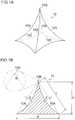
- an example of quadrangular pyramidal needle-like protruding portionsis described, however, the present invention is not limited to this shape.
- the microneedle (needle-like protruding portion) 10 formed on the transdermal-absorption sheetneeds to be shaped as follows so as to be stuck several hundred ⁇ m deep into the surface of the skin: (1) The tip is sufficiently pointed, and the diameter of the needle penetrating the skin is sufficiently small (the aspect ratio of length/diameter is high), and (2) the microneedle has a sufficient strength (the needle does not bend).
- a ridge line 10A of the microneedle 10is preferably shaped to be curved toward the inside of the microneedle.
- the microneedle with such a shapecan be made difficult to bend by sufficiently sharpening the tip, while widening the root.
- the ridge lines 10A, 10A of a quadrangular pyramidal microneedlepreferably extend from a quadrangular pyramidal surface 10C between the ridge lines.
- the shape of the microneedle 10is preferably such that a bottom surface is within the range of 0.1 ⁇ m or more and 1,000 ⁇ m or less on a side X, and 0.3 ⁇ m or more and 3,000 ⁇ m or less in height. More preferably, the bottom surface is within the range of 10 ⁇ m or more and 400 ⁇ m or less on a side X, and 30 ⁇ m or more and 1,200 ⁇ m or less in height.
- the maximum depth Z of curve of the ridge line 10Ais preferably 0.04 ⁇ L or more and 0.2 ⁇ L or less.
- the radius of curvature R of a tip 10B of the microneedle, which indicates sharpness of the microneedle 10is preferably 20 ⁇ m or less, and more preferably 15 ⁇ m or less.
- Figures 1A and 1Bdepict the quadrangular pyramidal microneedle 10.
- a conical microneedle depicted in Figures 2A and 2B and microneedles having other pyramids such as a triangular pyramidpreferably have similar sizes.
- the diameter X of the bottom surfaceis preferably within the range of 0.1 ⁇ m or more and 1,000 ⁇ m or less, and more preferably within the range of 50 ⁇ m or more and 500 ⁇ m or less.
- the maximum depth Z of curve of the conical surfaceis preferably 0.04 ⁇ L or more and 0.2 ⁇ L or less.
- the transdermal-absorption sheetforms a protruding portion array in which the microneedles are arranged in a two-dimensional array.
- the radius of curvature R of the tip 10B of the microneedleis preferably 20 ⁇ m or less.
- the transdermal-absorption sheetneeds to contain a drug, but many drugs are expensive. Thus, it is economically important to contain the drug in the transdermal-absorption sheet so that the drug concentrates at the portion of each microneedle.
- Figures 3A to 3Care process diagrams illustrating production of a mold.
- an original plateis first produced which is used to produce a mold that allows the transdermal-absorption sheet to be manufactured.
- a first methodis to apply a photo resist to an Si substrate and then to expose and develop the photo resist. Then, etching such as RIE (Reactive Ion Etching) is performed on the photo resist to form an array of conical shape portions (protruding portions) 12 on a surface of the original plate 11.
- etchingsuch as RIE is performed so as to form the conical shape portions on the surface of the original plate 11, the conical shapes can be formed by carrying out the etching in an oblique direction while the Si substrate is being rotated.
- a second methodis a method of machining a metal substrate such as Ni using a cutting tool such as a diamond byte to form an array of the shape portions 12 shaped like quadrangular pyramids or the like on the surface of the original plate 11.
- the moldis produced. Specifically, as depicted in Figure 3B , the mold 13 is produced from the original plate 11. A method using Ni electrocasting or the like is generally employed for production of the mold 13. Since the original plate 11 has the shape of cones or pyramids (such as quadrangular pyramids) with pointed tips, four methods are conceived which enables to precisely transfer the shape of the original plate 11 to the mold 13 and then to peel off the mold 13 from the original plate 11, while manufacturing the mold 13 at low cost.
- a first methodis a method of pouring, into the original plate 11, a silicone resin containing PDMS (polydimethylcyloxane, for example, Sylgard 184 (registered trademark) manufactured by Dow Corning Toray Co., Ltd.) with a curing agent added thereto, heating and curing the silicone resin at 100°C, and then peeling the silicon resin off from the original plate 11.
- a second methodis a method of pouring, into the original plate 11, a UV (ultraviolet) curing resin that is curable by irradiation of ultraviolet light, irradiating the UV curing resin with ultraviolet light in a nitrogen atmosphere, and then peeling the UV curing resin off from the original plate 11.
- a third methodis a method of pouring a solution of a plastic resin such as polystyrene or PMMA (polymethylmetacrylate) dissolved into an organic solvent, into the original plate 11 coated with a release agent, volatilizing the organic solvent by means of drying to cure the plastic resin, and then peeling the plastic resin off from the original plate 11.
- a fourth methodis a method of producing an inverted structure by means of Ni electrocasting.
- the mold 13is produced in which needle-like recessed portions 15 that are inverted shapes of cones or pyramids on the original plate 11 are arranged in a two-dimensional array.
- the mold 13 produced as described aboveis depicted in Figure 3C .
- the mold 13can be easily produced any number of times using any of the above-described four methods.
- a frame 14is installed on the mold 13 manufactured in Figure 3C .
- Figures 4A to 4Dare diagrams depicting that the frame 14 is installed on the mold.
- Figures 4A and 4Bare a plan view and a perspective view of a case where the frame is provided at the periphery of the mold 13, respectively.
- Figures 4C and 4Dare a plan view and a perspective view of a case where a plurality of molds 13 are joined together and the frame 14 is also provided inside the mold, respectively.
- Provision of the frame 14allows a solution of a polymer resin (hereinafter also referred to as a "polymer solution”) to be prevented from flowing out from the mold 13 when the functional film is formed to a desired film thickness.
- a polymer solutionhereinafter also referred to as a "polymer solution”
- a step (level difference) between the mold 13 and the frame 14is preferably 50 ⁇ m or more and 10 mm or less.
- the molds in Figures 4A to 4Dare configured to enable the mold 13 and the frame 14 to be separated from each other, but the mold 13 and the frame 14 may be integrated together.
- the frame 14can be removed in a drying step and a peeling-off step following the filling step.
- a plurality of molds 13are joined onto a substrate 17 and the plurality of molds 13 are joined to one another, using an adhesive. Then, the frame 14 is installed at the periphery of a side surface of the mold 13 and inside the mold 13.
- FIG. 5depicts an embodiment of another preferred mold 13.
- a needle-like recessed portion 15includes a tapered inlet portion 15A that is narrower in a depth direction from the front surface of the mold 13, an intermediate recessed portion 15B with a constant width in the depth direction, and a tip recessed portion 15C that is tapered in the depth direction.
- the angle ⁇ of the taperis desirably within the range of 10° to 20°.
- the tapered inlet portion 15Aallows the needle-like recessed portion 15 to be easily filled with the polymer solution.
- Figure 6depicts an embodiment of a mold complex 18 that is more preferable in executing the method for manufacturing the transdermal-absorption sheet.
- Portion (A) of Figure 6depicts the mold complex 18.
- Portion (B) of Figure 6is an enlarged view of a circled portion in portion (A).
- the mold complex 18includes the mold 13 in which an air vent hole 15D is formed at the tip (bottom) of each needle-like recessed portion 15 and a gas permeable sheet 19 laminated to a back surface of the mold 13 and formed of a material that allows gas to permeate, while preventing liquid from permeating.
- the air vent hole 15Dis formed as a through-hole that penetrates the back surface of the mold 13.
- the back surface of the mold 13refers to a surface on the side of the mold 13 on which the air vent hole 15D is formed.
- a tip of the needle-like recessed portion 15communicates with the atmosphere via the air vent hole 15D and the gas permeable sheet 19.
- the use of the mold complex 18 as described aboveallows only the air present in the needle-like recessed portions 15 to be driven out from the needle-like recessed portions 15 while preventing permeation of the transdermal-absorption material solution filled in the needle-like recessed portions 15. This improves transferability with which the shape of the needle-like recessed portions 15 is transferred to the transdermal-absorption material and allows formation of sharper microneedles 10.
- the diameter D (diameter) of the air vent hole 15Dis preferably within the range of 1 to 50 ⁇ m.
- a diameter D of the air vent hole 15D of less than 1 ⁇ mfails to allow the air vent hole to sufficiently accomplish the functions thereof.
- a diameter D of the air vent hole 15D of more than 50 ⁇ mis likely to cause the sharpness of the tip of the moulded microneedle 10 to be degraded.
- gas permeable sheet 19 formed of a material that allows gas to permeate while preventing liquid from permeatingfor example, latex (Asahi Kasei Chemicals Corporation) may be suitably used.
- an elastic raw material and a metallic raw materialmay be used as a material used for the mold 13.
- the elastic raw materialis preferable and a raw material with high gas permeability is more preferable.
- the oxygen permeabilitywhich is representative of the gas permeability, is preferably more than 1 ⁇ 10 -12 (mL/s ⁇ m 2 ⁇ Pa) and more preferably more than 1 ⁇ 10 -10 (mL/s ⁇ m 2 ⁇ Pa). Setting the gas permeability to within the above-described range allows the air present in the recessed portions in the mold 13 to be driven out from the mold side, allowing manufacture of microarray needles with few defects.
- examples of such raw materialinclude materials obtained by melting a silicone resin (for example, Sylgard 184 (registered trademark) manufactured by Dow Corning Toray Co., Ltd. or KE-1310ST (product number) manufactured by Shin-Etsu Chemical Co., Ltd.), a UV curing resin, or a plastic resin (for example, polystyrene or PMMA (polymethylmethacrylate)), and materials obtained by dissolving any of above resins into a solvent.
- silicone resinfor example, Sylgard 184 (registered trademark) manufactured by Dow Corning Toray Co., Ltd. or KE-1310ST (product number) manufactured by Shin-Etsu Chemical Co., Ltd.
- a plastic resinfor example, polystyrene or PMMA (polymethylmethacrylate)
- examples of the metallic raw materialinclude Ni, Cu, Cr, Mo, W, Ir, Tr, Fe, Co, MgO, Ti, Zr, Hf, V, Nb, Ta, ⁇ -aluminum oxide, zirconium oxide, stainless steel (for example, a STAVAX (trademark) material manufactured by Bohler-Uddeholm KK), and alloys thereof.
- a material similar to the material of the mold 13may be used.
- the polymer solutionthat is a solution of the polymer resin used for the present embodiment is described.
- a biocompatible resinis used as a raw material for the resin polymer used for the polymer solution. It is preferable to use, as such a resin, sugar such as glucose, maltose, pullulan, chondroitin sulfate, sodium hyaluronate, hydroxypropyl cellulose, or hydroxyethyl starch, protein such as gelatin, polylactate, or a biodegradable polymer such as a lactic acid-glycollic acid copolymer.
- a gelatin-based materialshave an adhesion with many base materials and have a high gel strength as materials to be gelated.
- the gelatin-based materialscan be suitably used during a peeling-off step described below because the materials can be brought into tight contact with the base material to allow the functional film to be peeled off from the mold using the base material.
- the density of the resinis preferably such that 10 to 50% resin polymer is contained in the solution, though the density depends on the type of the material.
- a solvent used for dissolutionmay be other than hot water as long as the solvent has volatility, and methylethylketone (MEK), alcohol, or the like may be used.
- MEKmethylethylketone
- a drug to be supplied to the inside of the human bodymay concurrently be dissolved into a solution of the polymer resin in accordance with the application.
- the solutioncan be prepared by dissolving water-soluble powder into water, and after the dissolution, adding a chemical to the solution. If the material is difficult to dissolve into water, the material may be dissolved on heating.
- the temperaturemay be selected as needed depending on the type of the polymer material, but the material is preferably heated at approximately 60°C or less.
- the solutioncan be prepared by melting the raw material and the chemical on heating. The heating temperature is preferably a temperature at which the raw material is melted, and is specifically approximately 150°C.
- the polymer solution containing the drugis referred to as the drug-containing solution, and the polymer solution containing no drug is referred to as the non-drug-containing solution, as needed.
- the viscosity of the solution of the polymer resinis preferably 100 Pa ⁇ s or less, and more preferably 10 Pa ⁇ s or less for the drug-containing solution.
- the viscosity of the solution of the polymer resinis preferably 2,000 Pa ⁇ s or less, and more preferably 1,000 Pa ⁇ s or less for the non-drug-containing solution. Appropriate adjustment of the viscosity of the solution of the polymer resin facilitates injection of the solution into the recessed portions of the mold.
- the drug contained in the polymer solutionis not limited as long as the drug has the functions of a drug.
- the drugis preferably selected from the group consisting of peptide, protein, nucleic acid, polysaccharide, a vaccine, a medical compound belonging to a water-soluble low-molecular-weight compound, and a cosmetic component.
- the water-soluble polymer substance contained in the drug-containing layerone that does not interact with the drug contained in the layer is preferably used.
- proteinwhen a chargeable polymer substance is mixed with the protein, the protein and the polymer substance electrostatically interact with each other to form an aggregate, which is cohered and precipitated. Therefore, when a chargeable substance is used in the drug, a water-soluble polymer substance with no charge such as hydroxyethyl starch or dextran is preferably used.
- a method for manufacturing the transdermal-absorption sheet using the mold 13 manufactured as described aboveis described.
- the mold 13 with the two-dimensionally arranged needle-like recessed portions 15is placed on a base 20.
- Two sets of a plurality of needle-like recessed portions 15, each set including 5 ⁇ 5 two-dimensionally arranged needle-like recessed portions 15,are formed in the mold 13.
- a liquid feeding apparatus 36is prepared which has a tank 30 housing a drug-containing solution 22, a pipe 32 connected to the tank, and a nozzle 34 connected to a tip of the pipe 32.
- Figure 8depicts a schematic perspective view of the tip of the nozzle.
- the tip of the nozzle 34includes a lip portion 34A that is a flat surface and a slit-shaped opening 34B.
- the slit-shaped opening 34Ballows a plurality of needle-like recessed portions 15 constituting one line to be simultaneously filled with the drug-containing solution 22.
- the size (length and width) of the opening 34Bis selected as needed in accordance with the number of needle-like recessed portions 15 to be filled at a time.
- An increased length of the opening 34Ballows an increased number of needle-like recessed portions 15 to be filled at a time with the drug-containing solution 22. Thus, productivity can be improved.
- Figure 9depicts a schematic perspective view of a tip of another nozzle.
- the lip portion 34A at the tip of the nozzle 34has two slit-shaped openings 34B.
- the two openings 34Ballow a plurality of needle-like recessed portions 15 constituting two lines to be simultaneously filled with the drug-containing solution 22.
- an elastic raw material and a metallic raw materialmay be used.
- Teflonregistered trademark
- stainless steelSUS
- titaniummay be used.
- a filling stepis described with reference to Figure 7B .
- the opening 34B in the nozzle 34is aligned over the needle-like recessed portions 15.
- the lip portion 34A of the nozzle 34is in contact with the front surface of the mold 13.
- the drug-containing solution 22is fed from the liquid feeding apparatus 36 to the mold 13, and the needle-like recessed portions 15 are filled with the drug-containing solution 22 through the opening 34B in the nozzle 34.
- a plurality of needle-like recessed portions 15 constituting one lineare simultaneously filled with the drug-containing solution 22.
- the needle-like recessed portions 15may be filled with the drug-containing solution 22 one by one.
- the use of the nozzle 34 depicted in Figure 9allows a plurality of needle-like recessed portions 15 constituting a plurality of lines to be simultaneously filled with the drug-containing solution 22 so that filling is performed on a plurality of lines at a time.
- the drug-containing solution 22can be sucked by sucking the back surface of the mold 13, promoting filling of the inside of the needle-like recessed portions 15 with the drug-containing solution 22.
- the liquid feeding apparatus 36is relatively moved in a direction perpendicular to a length direction of the opening 34B, to move the nozzle 34 to the needle-like recessed portions 15 not filled with the drug-containing solution 22, as depicted in Figure 7C .
- the opening 34B in the nozzle 34is aligned over the needle-like recessed portions 15.
- the nozzle 34Since the nozzle 34 is moved with the lip portion 34A of the nozzle 34 and the front surface of the mold 13 in contact with each other, the nozzle 34 can scrape off the drug-containing solution 22 remaining on the surface of the mold 13 except on the needle-like recessed portions 15. This enables the drug-containing solution 22 to be prevented from remaining on the mold 13 except on the needle-like recessed portions 15.
- the pressing pressure with which the nozzle 34 is pressed against the mold 13 at the time of movementis preferably minimized.
- at least one of the mold 13 and the nozzle 34is desirably formed of a flexible, elastically deformable raw material.
- the filling step in Figure 7B and the moving step in Figure 7Care repeated to fill the 5 ⁇ 5 two-dimensionally arranged needle-like recessed portions 15 with the drug-containing solution 22.
- the liquid feeding apparatus 36is moved to the adjacent 5 ⁇ 5 two-dimensionally arranged needle-like recessed portions 15, and the filling step in Figure 7B and the moving step in Figure 7C are repeated.
- the adjacent 5 ⁇ 5 two-dimensionally arranged needle-like recessed portions 15are also filled with the drug-containing solution 22.
- the above-described filling step and moving stepmay be in (1) a form in which the needle-like recessed portions 15 are filled with the drug-containing solution 22 while the nozzle 34 is being moved or (2) a form in which, while the nozzle 34 is in motion, the nozzle 34 is temporarily stopped over the needle-like recessed portions 15 to fill the needle-like recessed portions 15 with the drug-containing solution 22, and the nozzle 34 is moved again after the filling. Between the filling step and the moving step, the lip portion 34A of the nozzle 34 is in contact with the front surface of the mold 13.
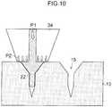
- Figure 10is a partially enlarged view of the tip of the nozzle 34 and the mold 13 during filling of the needle-like recessed portions 15 with the drug-containing solution 22.
- filling of the inside of the needle-like recessed portions 15 with the drug-containing solution 22can be promoted by applying a pressuring force P1 into the nozzle 34.
- a pressing force P2 with which the nozzle 34 is brought into contact with the front surface of the mold 13is preferably set equal to or stronger than the pressuring force P1 in the nozzle 34. Setting the pressing force P2 ⁇ the pressuring force P1 enables the drug-containing solution 22 to be restrained from leaking from the needle-like recessed portions 15 to the front surface of the mold 13.
- Figure 11is a partially enlarged view of the tip of the nozzle 34 and the mold 13 during movement of the nozzle 34.
- a pressing force P3 with which the nozzle 34 is brought into contact with the front surface of the mold 13is preferably set weaker than the pressing force P2 with which the nozzle 34 is brought into contact with the front surface of the mold 13 while filling is performed. This is intended to reduce damage to the mold 13 and to suppress deformation of the mold 13 associated with compression.
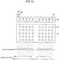
- FIG 12is a diagram illustrating the relation between the liquid pressure in the nozzle and feeding of the drug-containing solution.
- feeding of the drug-containing solution 22is started before the nozzle 34 is positioned over the needle-like recessed portions 15. This is intended to reliably fill the needle-like recessed portions 15 with the drug-containing solution 22.
- the drug-containing solution 22is continuously fed to the mold 13 until the filling of the plurality of needle-like recessed portions 15 composed of the 5 ⁇ 5 needle-like recessed portions 15 is complete.
- the feeding of the drug-containing solution 22 to the mold 13is stopped before the nozzle 34 is positioned over the fifth line of the needle-like recessed portions 15. This allows the drug-containing solution 22 to be prevented from overflowing the needle-like recessed portions 15.
- the liquid pressure in the nozzle 34is elevated in areas where the nozzle 34 is not positioned over the needle-like recessed portions 15.
- the needle-like recessed portions 15are filled with the drug-containing solution 22 to lower the liquid pressure in the nozzle 34. The variation in liquid pressure is repeated.
- the nozzle 34is moved to the adjacent plurality of needle-like recessed portions 15 composed of the 5 ⁇ 5 needle-like recessed portions 15.
- the feeding of the drug-containing solution 22is preferably stopped at the time of movement to the adjacent plurality of needle-like recessed portions 15 composed of the 5 ⁇ 5 needle-like recessed portions 15. A long distance is present between the fifth line of needle-like recessed portions 15 and the next first line of needle-like recessed portions 15.
- the liquid pressure in the nozzle 34may be excessively high.
- the drug-containing solution 22may flow out from the nozzle 34 onto an area other than the needle-like recessed portions 15 in the mold 13.
- the liquid pressure in the nozzle 34is detected so that the feeding of the drug-containing solution 22 is stopped upon determining that the liquid pressure is to be excessively high.
- the processproceeds to a step of forming a polymer sheet with needle-like protruding portions each formed on a surface of the sheet, the polymer sheet including a drug-containing layer composed of the drug-containing solution 22 and a non-drug-containing layer composed of a non-drug-containing solution.
- the needle-like protruding portionshave inverted shapes of the needle-like recessed portions.
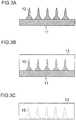
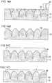
- FIG. 13AA first aspect is described with reference to Figures 13A to 13C .
- the needle-like recessed portions 15 in the mold 13are filled with the drug-containing solution 22 through the nozzle 34.
- a non-drug-containing solution 24is applied onto a surface of the drug-containing solution 22 using a dispenser.
- a bar coating method, a spin coating method, and an application using a spray or the likeare applicable.
- the drug-containing solution 22 and the non-drug-containing solution 24are dried and solidified to form a polymer sheet 1 including a drug-containing layer 26 and a non-drug-containing layer 28.
- pressurization from the front surface of the mold 13 and reduced pressure suction (vacuum suction) from the back surface of the mold 13may be preferably performed in order to promote filling of the inside of the needle-like recessed portions 15 with the drug-containing solution 22 and the non-drug-containing solution 24.
- FIG. 14Athe needle-like recessed portions 15 in the mold 13 are filled with the drug-containing solution 22 through the nozzle 34. Then, as depicted in Figure 14B , the drug-containing solution 22 is dried and solidified to form the drug-containing layer 26 in each of the needle-like recessed portions 15.
- the tip of the needle-like recessed portion 15can be filled with the drug-containing solution 22 by the pressurization from the front surface of the mold 13 and the reduced pressure suction from the back surface of the mold 13.
- the non-drug-containing solution 24is applied onto the surface of the drug-containing layer 26 using the dispenser.
- the dispenserfor example, a bar coating method, a spin coating method, and an application using a spray or the like are applicable. Since the drug-containing layer 26 is solidified, the drug in the drug-containing layer 26 can be restrained from diffusing to the non-drug-containing solution 24.
- the non-drug-containing solution 24is dried and solidified to form the polymer sheet 1 including the drug-containing layer 26 and the non-drug-containing layer 28.
- pressurization from the front surface of the mold 13 and reduced pressure suction from the back surface of the mold 13are preferably performed in order to promote filling of the inside of the needle-like recessed portions 15 with the drug-containing solution 22 and the non-drug-containing solution 24.
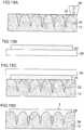
- FIG. 15Athe needle-like recessed portions 15 in the mold 13 are filled with the drug-containing solution 22 through the nozzle 34.
- the non-drug-containing solution 24is applied onto a surface of another support 29.
- the support 29is not limited, but for example, polyethylene, polyethylene terephtalate, polycarbonate, polypropylene, an acrylic resin, triacetylcellulose, or glass may be used.
- the non-drug-containing solution 24 formed on the support 29is laid on the mold 13 with the needle-like recessed portions 15 filled with the drug-containing solution 22.
- the drug-containing solution 22 and the non-drug-containing solution 24are dried and solidified to form the polymer sheet 1 including the drug-containing layer 26 and the non-drug-containing layer 28.
- pressurization from the front surface of the mold 13 and reduced pressure suction from the back surface of the mold 13are preferably performed in order to promote filling of the inside of the needle-like recessed portions 15 with the drug-containing solution 22.
- the step of drying and solidificationis a step in which the drug-containing solution 22 and/or the non-drug-containing solution 24 is dried to solidify the drug-containing solution 22 and/or the non-drug-containing solution 24 in each of the needle-like recessed portions 15.
- a method for drying the drug-containing solution 22 and/or the non-drug-containing solution 24may be a step of volatilizing a solvent in the polymer solution.
- the methodis not particularly limited, and for example, a method such as heating, air blowing, or pressure reduction may be used. Specifically, a method of blowing warm air against the solution at 0.1 to 10 m/s may be used.
- the warm airis preferably at a temperature at which the drug in the drug-containing solution 22 is not thermally degraded.
- the drug-containing solution 22is solidified by means of drying and contracted compared to the state of the drug-containing solution 22 at the time of application.
- the drug-containing layer 26can be easily peeled off from the needle-like recessed portions 15 in the mold 13.
- the non-drug-containing solution 24similarly contracts, and thus, the contraction occurs in the direction of film thickness of the sheet given that the solidified drug-containing layer 26 and/or non-drug-containing layer 28 is in tight contact with the mold 13, reducing the film thickness. Furthermore, when the drug-containing layer 26 and/or non-drug-containing layer 28 peels off from the mold 13 during drying, the polymer sheet 1 also contracts in a surface direction and is thus distorted or curled.
- the polymer sheet 1When the polymer sheet 1 is peeled off from the mold 13 in the state in which the drug-containing layer 26 and/or non-drug-containing layer 28 in the needle-like recessed portions 15 is not sufficiently dried, a defect is likely to occur in which the shapes of the needle-like protruding portions on the polymer sheet 1 are broken or bent. Thus, the polymer sheet 1 is preferably not peeled off from the mold 13 during drying.
- the processproceeds to a peeling-off step of peeling the polymer sheet 1 off from the mold 13.
- a method for peeling the polymer sheet 1 off from the mold 13is not limited.
- the needle-like protruding portionsare desirably prevented from being bent or broken at the time of peeling-off.
- a sheet-like base material 40 provided with a sticky adhesive layeris attached onto the polymer sheet 1, and then the polymer sheet 1 can be peeled off by turning the base material 40 over at an end of the polymer sheet 1.
- this methodmay cause the needle-like protruding portions to be bent.
- a methodmay be applied in which suckers (not depicted in the drawings) are installed on the base material 40 on the polymer sheet 1 and the base material 40 is then sucked using air and lifted perpendicularly.
- the support 29may also be used as the base material 40.
- the mold 13is preferably composed of a material that is very easy to peel off. Furthermore, the mold 13 composed of a highly elastic soft material allows relaxation of stress applied to the microneedles at the time of peeling-off.
- FIG. 18depicts a transdermal-absorption sheet 2 composed of the polymer sheet 1 peeled off from the mold 13.
- the transdermal-absorption sheet 2is composed of the base material 40, the drug-containing layer 26 formed on the base material 40, and the layer 28 not substantially containing the drug.
- Needle-like protruding portions 4 on the transdermal-absorption sheet 2are each composed of a truncated cone portion 5 and a needle portion 6 on the truncated cone portion 5.
- the needle portion 6mainly has a conical or pyramidal needle portion and a cylindrical or rectangular columnar body portion.
- the needle-like protruding portions 4are not limited to this shape.
- Figure 19depicts an original plate for the mold.
- Portion (A) of Figure 19is a plan view
- portion (B) of Figure 19is a side view.
- the original plate 11 as depicted in Figure 19was produced by grinding a surface of a smooth Ni plate having a side of 40 mm so as to form shape portions 12 each with a needle-like structure that are arranged at a pitch L of 1,000 ⁇ m in two-dimensional array with 10 columns and 10 rows.
- Each shape portions 12 with a needle-like structureincludes: a truncated cone 50 with a bottom surface diameter D1 of 500 ⁇ m and a height H1 of 150 ⁇ m; and a cone 52 formed on the truncated cone 50 and having a diameter D2 of 300 ⁇ m and a height H2 of 500 ⁇ m.
- a filmwas formed on the original plate 11 to have a thickness of 0.6 mm using silicone rubber (SILASTIC (registered trademark), MDX4-4210 (product number) manufactured by Dow Corning Toray Co., Ltd.). The film was thermally cured with tips of the cones of the original plate 11 allowed to protrude 50 ⁇ m from a surface of the film and was then peeled off.
- an inverted article made of silicone rubberwhich had through-holes with a diameter of approximately 30 ⁇ m.
- the inverted article made of silicone rubberwas trimmed so as to leave a planar portion with a side of 30 mm on whose central portion needle-like recessed portions were formed with two-dimensionally arranged in 10 columns and 10 rows.
- the portion thus obtainedwas used as a mold.
- a surface of the mold corresponding to the wider opening of each of the needle-like protruding portionswas the front surface of the mold.
- a surface of the mold with the through-holes (air vent holes) with a diameter of 30 ⁇ mwas the back surface of the mold.
- Hydroxyethyl starch(manufactured by Fresenius Kabi) was dissolved into water to prepare an 8% water solution.
- As a drug2 wt% human serum albumin (manufactured by Wako Pure Chemical Industries, Ltd.) and 0.7 mass% Evans blue dye (manufactured by Wako Pure Chemical Industries, Ltd.) were added to the solution to obtain the drug-containing solution.
- a gas permeable film(NTF-8031 (product number) manufactured by NITTO DENKO CORPORATION) with a side of 15 mm was placed on a horizontal vacuum platform, and the mold was installed on the gas permeable film with the front surface of the mold facing upward. The back surface of the mold was decompressed with a suction pressure of 50 kPa to fix the gas permeable film and the mold to the vacuum platform.
- a SUS (stainless steel) nozzle shaped as depicted in Figure 8was prepared, and a slit-like opening with a length of 12 mm and a width of 0.2 mm was formed in the center of a lip portion with a length of 20 mm and a width of 2 mm.
- the nozzlewas attached to a syringe.
- the inside of the syringe and the nozzlewas filled with the drug-containing solution of 3 mL.
- the nozzlewas aligned in order for the opening to be parallel to the first line composed of a plurality of needle-like recessed portions formed in the front surface of the mold.
- the nozzlewas pressed against the mold with a pressure of 0.14 kgf/cm 2 at a distance of 2 mm from the first line in a direction opposite to the second line.
- the drug-containing solutionwas discharged using the dispenser through the opening at 0.31 ⁇ L/sec for 10 seconds. Movement of the nozzle was stopped at a distance of 2 mm from the tenth line of the plurality of two-dimensionally arranged needle-like recessed portions in a direction opposite to the ninth line.
- the nozzlewas then separated from the mold.
- the mold filled with the drug-containing solution as described abovewas cut at a position around and 1 mm outside the plurality of two-dimensionally arranged needle-like recessed portions. Drying was performed in a thermohygrostat bath at 30°C and 40% for 30 minutes to form the drug-containing layer. After the drying, a tape with a low adhesive force was attached to the front surface of the mold and then peeled off to remove the drug-containing layer adhering to areas other than the needle-like recessed portions in the mold.
- the mold and the tape with the low adhesive forcewere each immersed in 1 mL of water in a 5 mL lidded container.
- the lid of the containerwas loosened, and the mold and the tape were pressurized in a pressurized-type degassing unit at 0.5 MPa for 10 minutes.
- the containerwas then closed, and ultrasonic cleaning was carried out for 30 minutes.
- each of the solutionswas measured for absorbance at a wavelength of 620 nm using a microplate absorbance reader (Sunrise Series manufactured by TECAN).
- the contents of the drug-containing layer in the needle-like recessed portions and in the areas other than the needle-like recessed portions in the moldwere calculated.
- silicone rubberwas formed into a film having a thickness of 0.7 mm, thermally cured without through-holes being fomed in the back surface thereof, and peeled off to produce the inverted article of the silicone rubber.
- the drug-containing solutionwas prepared as is the case with Example 1.
- the moldwas installed on the horizontal vacuum platform with the front surface of the mold facing upward.
- the back surface of the moldwas decompressed with a suction pressure of 50 kPa to fix the mold to the vacuum platform.
- a SUS (stainless steel) nozzle shaped as depicted in Figure 8was prepared, and a slit-like opening with a length of 12 mm and a width of 0.2 mm was formed in the center of the lip portion with a length of 20 mm and a width of 2 mm.
- the nozzlewas attached to the syringe.
- the inside of the syringe and the nozzlewas filled with the drug-containing solution of 3 mL.
- the nozzlewas aligned in order for the opening to be parallel to the first line composed of the plurality of needle-like recessed portions formed in the front surface of the mold.
- the nozzlewas pressed against the mold with a pressure of 0.42 kgf/cm 2 at a distance of 2 mm from the first line in the direction opposite to the second line.
- the nozzlekept pressed against the mold, was moved in the direction perpendicular to the length direction of the opening at 1 mm/sec. The nozzle was stopped when the opening in the nozzle reached the central position of the first line of needle-like recessed portions. The nozzle was pushed into the mold with a pressure of 2.8 kgf/cm 2 . Moreover, air was blown through the inside of the nozzle to pressure the mold at 0.2 MPa ( ⁇ 2.0 kgf/cm 2 ) for one minute. Thus, the needle-like recessed portions in the first line in the mold were filled with the drug-containing solution.
- the pressure in the nozzlewas released, and then the pressing pressure of the nozzle against the mold was recovered to 0.42 kgf/cm 2 .
- the nozzlekept pressed against the mold, was moved to the central position of the needle-like recessed portions in the second line. Movement of the nozzle was stopped, and the needle-like recessed portions in the second line in the mold were filled with the drug-containing solution as is the case with the first line. This was repeated to fill up to the tenth line of needle-like recessed portions with the drug-containing solution. Movement of the nozzle was stopped at a distance of 2 mm from the tenth line of the plurality of two-dimensionally arranged needle-like recessed portions. The nozzle was then separated from the mold.
- the mold filled with the drug-containing solution as described abovewas cut at a position around and 1 mm outside the plurality of two-dimensionally arranged needle-like recessed portions.
- the moldwas dried in the thermohygrostat bath at 30°C and 40% for 30 minutes to form the drug-containing layer. After the drying, a tape with a low adhesive force was attached to the front surface of the mold and then peeled off to remove the drug-containing layer adhering to the areas other than the needle-like recessed portions in the mold.
- the mold and the tape with the low adhesive forcewere each immersed in 1 mL of water in a 5 mL lidded container.
- the lid of the containerwas loosened, and the mold and the tape were pressurized in the pressurized-type degassing unit at 0.5 MPa for 10 minutes.
- the containerwas then closed, and ultrasonic cleaning was carried out for 30 minutes.
- each of the solutionswas measured for absorbance at a wavelength of 620 nm using a microplate absorbance reader (Sunrise Series manufactured by TECAN).
- the contents of the drug-containing layer in the needle-like recessed portions and in the areas other than the needle-like recessed portions in the moldwere calculated.
- the content of the drug-containing layerwas calculated as is the case with Example 1.
- the contents of the drug-containing layer in the needle-like recessed portions and in the areas other than the needle-like recessed portions in the moldwere calculated as is the case with Example 2 except that, in formation of the drug-containing layer, the pressing pressure on the nozzle and the mold was changed from 0.42 kgf/cm 2 to 0.83 kgf/cm 2 .
- Table 1depicts evaluation results for Examples 1 to 3. ⁇ Table 1 ⁇ Mold Pressing pressure [kgf/cm2] Filling amount of drug-containing layer in needle-like recessed portions [mg] Deposition amount of drug-containing layer in areas other than needle-like recessed portions [mg] Example 1 Through-holes formed in back surface 0.14 0.287 0.0003 Example 2 No through-hole in back surface 0.42 0.216 - Example 3 No through-hole in back surface 0.83 0.187 -
- the needle-like recessed portions in the moldwere 3.10 ⁇ L (equivalent to 0.310 mg in terms of a density of 1), the needle-like recessed portions were filled with the appropriate amount of drug-containing layer in all of Examples 1 to 3.
- the amount of drug adhering to the areas other than the needle-like recessed portionsincreases as pressing pressure decreases.
- the amount of drug adhering to the areas other than the needle-like recessed portionswas approximately 0.1% of the amount of drug in the needle-like recessed portions.
- the moldwas produced as is the case with Example 2.
- Hydroxyethyl starch(manufactured by Fresenius Kabi) was dissolved into water to prepare an 8% water solution.
- Chondroitin sulfate(manufactured by Maruha Nichiro Corporation) was dissolved into water to prepare a 30% water solution as a non-drug-containing solution.
- the drug-containing layerwas formed as is the case with Example 1.
- the non-drug-containing solutionwas applied onto a surface of slide glass with a film thickness of 210 ⁇ m.
- the moldwas placed on the slide glass such that the front surface of the mold was brought into contact with the applied film and pneumatically pressed in the pressurized-type degassing unit (TAC Series manufactured by SAKURA SEIKI Co., Ltd.) at 0.35 MPa for 10 minutes.
- the slide glasswas taken out of the pressurized-type degassing unit, and placed in the thermohygrostat bath (small environmental test chamber manufactured by ESPEC) with the slide glass facing downward to be dried at 30°C and 40% for eight hours.
- the slide glasscorresponds to the support 29 and the base material 40 described above.
- the moldalong with the gas permeable film, was peeled off from the polymer layer on the slide glass.
- a transdermal-absorption sheet with a three-dimensional array structurewas formed which was composed of the drug-containing layer and the non-drug-containing layer and in which the human growth hormone was eccentrically located in the tip.
- the transdermal-absorption sheet produced as described abovewas evaluated for a drug filling rate to the needle-like protruding portions.
- the transdermal-absorption sheetwas observed using a confocal fluorescence microscope (manufactured by NIKON CORPORATION; C1plus +TE2000U (product number)).
- the rate of the FITC (fluorescein isothiocyanate) fluorescence intensity of a 350- ⁇ m portion of the tip of each needle-like protruding portion in the FITC fluorescence intensity of the whole transdermal-absorption sheetwas measured as the filling rate. Then, the filling rate was approximately 75%, indicating that the tip of the needle portion was filled with the drug at a high rate.
- the moldwas produced as is the case with Example 2.
- the drug-containing solutionwas prepared as is the case with Example 4.
- Hydroxyethyl starchmanufactured by Fresenius Kabi
- sodium hyaluronatemolecular weight: 900 thousand to 1.5 million; manufactured by Maruha Nichiro Corporation
- the drug-containing layerwas formed as is the case with Example 1.
- the non-drug-containing layerwas formed as is the case with Example 4.
- the peeling-off stepwas executed as is the case with Example 4.
- the transdermal-absorption sheet produced as described abovewas evaluated for the drug filling rate to the needle-like protruding portions.
- the transdermal-absorption sheetwas observed using the confocal fluorescence microscope (manufactured by NIKON CORPORATION; C1plus + TE2000U).
- the rate of the FITC fluorescence intensity of a 350- ⁇ m portion of the tip of each needle-like protruding portion in the FITC fluorescence intensity of the whole transdermal-absorption sheetwas measured as the filling rate.
- the filling ratewas approximately 65%, indicating that the tip of the needle portion was filled with the drug at a high rate.
- the moldwas produced as is the case with Example 1.
- the drug-containing solutionwas prepared as is the case with Example 4.
- the non-drug-containing solutionwas prepared as is the case with Example 4.
- the drug-containing layerwas formed as is the case with Example 1.
- the non-drug-containing solutionwas applied onto the surface of the slide glass with a film thickness of 210 ⁇ m.
- the slide glasswas placed on the drug-containing layer formed on the mold which was placed on the vacuum platform via the gas permeable film so that the applied surface was brought into contact with the drug-containing layer, and was further decompressed at a suction pressure of 50 kPa for 20 minutes.
- the decompressionwas turned off, and the structure in which the layers from the gas permeable film to the slide glass were in tight contact with one another was removed from the vacuum platform.
- the samplewas placed in the thermohygrostat bath (small environmental test chamber manufactured by ESPEC) with the slide glass facing downward to be dried at 30°C and 40% for eight hours.
- the peeling-off stepwas performed as is the case with Example 4.
- the transdermal-absorption sheet produced as described abovewas evaluated for the filling rate to the needle-like protruding portions.
- the transdermal-absorption sheetwas observed using the confocal fluorescence microscope (manufactured by NIKON CORPORATION; C1plus + TE2000U).
- the rate of the FITC fluorescence intensity of a 350- ⁇ m portion of the tip of each needle-like protruding portion in the FITC fluorescence intensity of the whole transdermal-absorption sheetwas measured as the filling rate.
- the filling ratewas approximately 75%, indicating that the tip of the needle portion was filled with the drug at a high rate.
- the moldwas produced as is the case with Example 1.
- the drug-containing solutionwas prepared as is the case with Example 4.
- Hydroxyethyl starchmanufactured by Fresenius Kabi
- sodium hyaluronatemolecular weight: 900 thousand to 1.5 million; manufactured by Maruha Nichiro Corporation
- chondroitin sulfatemanufactured by Maruha Nichiro Corporation
- the drug-containing layerwas formed as is the case with Example 1.
- the non-drug-containing solutionwas applied onto the surface of the slide glass with a film thickness of 200 ⁇ m, and the slide glass was then dried in the thermohygrostat bath at a temperature of 60°C and a relative humidity of 20% for one hour. The slide glass was then taken out of the thermohygrostat bath.
- the intermediate layer solutionwas applied to the surface of the applied film after the drying with a film thickness of 100 ⁇ m.
- the slide glasswas then placed on the drug-containing layer formed on the mold placed on the vacuum platform via the gas permeable film so that the applied surface of the intermediate layer solution was brought into contact with the drug-containing layer, and was further decompressed at a suction pressure of 50 kPa for 20 minutes.
- the decompressionwas turned off, and the sample was removed from the vacuum platform in a state where the layers from the gas permeable film to the slide glass were brought into tight contact with each other.
- the samplewas placed in the thermohygrostat bath (small environmental test chamber manufactured by ESPEC) with the slide glass facing downward to be dried at 30°C and 40% for eight hours.
- the peeling-off stepwas performed as is the case with Example 4.
- the transdermal-absorption sheet produced as described abovewas evaluated for the drug filling rate to the needle-like protruding portions.
- the transdermal-absorption sheetwas observed using the confocal fluorescence microscope (manufactured by NIKON CORPORATION; C1plus + TE2000U).
- the rate of the FITC fluorescence intensity of a 350- ⁇ m portion of the tip of each needle-like protruding portion in the FITC fluorescence intensity of the whole transdermal-absorption sheetwas measured as the filling rate.
- the filling ratewas approximately 65%, indicating that the tip of the needle portion was filled with the drug at a high rate.
Landscapes
- Health & Medical Sciences (AREA)
- Dermatology (AREA)
- Life Sciences & Earth Sciences (AREA)
- Engineering & Computer Science (AREA)
- Veterinary Medicine (AREA)
- Public Health (AREA)
- General Health & Medical Sciences (AREA)
- Animal Behavior & Ethology (AREA)
- Biomedical Technology (AREA)
- Pharmacology & Pharmacy (AREA)
- Heart & Thoracic Surgery (AREA)
- Anesthesiology (AREA)
- Medical Informatics (AREA)
- Chemical & Material Sciences (AREA)
- Medicinal Chemistry (AREA)
- Hematology (AREA)
- Epidemiology (AREA)
- Media Introduction/Drainage Providing Device (AREA)
- Medicines Containing Antibodies Or Antigens For Use As Internal Diagnostic Agents (AREA)
- Pharmaceuticals Containing Other Organic And Inorganic Compounds (AREA)
- Medicinal Preparation (AREA)
- Medicines That Contain Protein Lipid Enzymes And Other Medicines (AREA)
Description
- The present invention relates to a method for manufacturing a transdermal-absorption sheet, and in particular, to a technique for concentrating a drug at needle-like protruding portions.
- In recent years, a method has been carried out in which a chemical is injected by using a transdermal-absorption sheet provided with needle-like protruding portions having a high aspect ratio and containing a drug to insert the needle-like protruding portions into the skin. In order to allow the transdermal-absorption sheet to be used as a drug, the drug needs to be mixed into the sheet. Many drugs are expensive, and thus, the drug needs to be contained in the sheet so as to concentrate at the needle-like protruding portions.
- As a method for manufacturing a transdermal-absorption sheet, a method is known in which a polymer solution or the like is poured into a mold on which needle-like recessed portions that are inverted shapes of needle-like protruding portions are formed, to transfer the shapes. For example,
PTL 1 discloses use of a stamper for microneedle sheets in which through-holes penetrating a parent material are made at the bottoms of the recessed portions.PTL 1 discloses a method of first coating a surface of the stamper with a solution of a diluted drug, subsequently scraping off extra solution using a squeegee or the like, drying the drug solution, and then coating the dried drug solution with a needle raw material. - Furthermore,
PTL 2 discloses a method for manufacturing a sheet in which microneedle-like protrusions are accumulated. In the method, the sheet can be accurately manufactured in one step by filling a flexible substrate with a thick liquid consisting of a mixture of a target substance and a base utilizing a centrifugal force, while drying and hardening the liquid US2008/0269685 discloses the formation of an array of microprotrusions by (a) providing a mold with cavities corresponding to the negative of the microprotrusions, (b) casting a solution comprising a biocompatible material and a solvent atop the mold, (c) removing the solvent, (d) demolding the resulting array from the mold, and (e) taking at least one measure to avoid the formation or adverse effects of bubbles.- {PTL 1} Japanese Patent Application Laid-Open No.
2011-078617 - {PTL 2} Japanese Patent Application Laid-Open No.
2009-195583 - In the method in
PTL 1, the drug solution is applied to the stamper, and the extra solution is scraped off using the squeegee or the like. Thus, the drug solution which is applied to the areas other than the recessed portions is not used to fill the recessed portions, leading to a loss in drug solution. - The method in
PTL 2 utilizes the centrifugal force and is thus not a continuous process but is a batch process. Consequently, the method inPTL 2 does not achieve high production efficiency. - In view of these circumstances, the present invention aims to provide a method which enables a drug to be concentrated at needle-like protruding portions and which further allows transdermal-absorption sheets to be manufactured at high production efficiency.
- A method for manufacturing a transdermal-absorption sheet according to an aspect of the present invention is for manufacturing a transdermal-absorption sheet with needle-like protruding portions each including a drug-containing layer and a non-drug-containing layer, the method including: a step of preparing a mold with two-dimensionally arranged needle-like recessed portions and a liquid feeding apparatus comprising a nozzle with an opening; a step of filling the two-dimensionally arranged needle-like recessed portions with a drug-containing solution by repeating a filling step of feeding the drug-containing solution from the liquid feeding apparatus to the mold and filling one or more of the needle-like recessed portions with the drug-containing solution through the nozzle aligned over the needle-like recessed portions in a state where the nozzle and a front surface of the mold are brought in contact with each other, and a moving step of moving the liquid feeding apparatus relative to the mold in a state where the nozzle and the front surface of the mold are brought in contact with each other; a step of forming a polymer sheet provided with needle-like protruding portions on a surface of the polymer sheet, the needle-like protruding portions each comprising a drug-containing layer composed of the drug-containing solution and a non-drug-containing layer composed of a non-drug-containing solution and having an inverted shape of the needle-like recessed portion; and a step of peeling the polymer sheet off from the mold.
- Preferably, in the filling step, the two-dimensionally arranged needle-like recessed portions are filled with the drug-containing solution so that filling is performed on one line or a plurality of lines at a time.
- Preferably, the filling step includes pressurizing an inside of the nozzle.
- Preferably, in the filling step, a pressing force with which the nozzle and the mold are brought into contact with each other is equal to or stronger than a pressurizing force inside the nozzle.
- Preferably, the filling step includes sucking a back surface of the mold with a reduced pressure.
- Preferably, the pressing force with which the nozzle and the mold are brought into contact with each other in the filling step is stronger than a pressing force with which the nozzle and the mold are brought into contact with each other in the moving step.
- Preferably, in the moving step, feeding of the drug-containing solution from the liquid feeding apparatus to the mold is stopped while the nozzle is positioned over an area other than the needle-like recessed portions in the mold.
- Preferably, in the moving step, feeding of the drug-containing solution from the liquid feeding apparatus to the mold is started before the nozzle is positioned over the needle-like recessed portions, and the feeding of the drug-containing solution to the mold is stopped before the nozzle is positioned over the area other than the needle-like recessed portions in the mold.
- Preferably, at least one of the nozzle and the front surface of the mold is made of an elastically deformable raw material.
- Preferably, the mold comprises an air vent hole at a tip of each of the needle-like recessed portions.
- Preferably, the step of forming the polymer sheet comprises a step of feeding the non-drug-containing solution to the mold with the needle-like recessed portions filled with the drug-containing solution, and then drying and solidifying the drug-containing solution and the non-drug-containing solution to form the drug-containing layer and the non-drug-containing layer.
- Preferably, the step of forming the polymer sheet comprises a step of drying and solidifying the drug-containing solution filled in the needle-like recessed portions in the mold to form the drug-containing layer, feeding the non-drug-containing solution to the mold in which the drug-containing layer is formed in the needle-like recessed portions, and then drying and solidifying the non-drug-containing solution to form the non-drug-containing layer.
- Preferably, the step of forming the polymer sheet comprises a step of applying the non-drug-containing solution onto a surface of another support, attaching the another support onto which the non-drug-containing solution is applied to the mold with the needle-like recessed portions filled with the drug-containing solution, and drying and solidifying the drug-containing solution and the non-drug-containing solution to form the drug-containing layer and the non-drug-containing layer.
- Preferably, the step of forming the polymer sheet comprises performing at least one of pressurization from the front surface of the mold and reduced pressure suction from the back surface of the mold, when drying and solidifying the drug-containing solution contained in the needle-like recessed portions in the mold.
- Preferably, the step of forming the polymer sheet comprises performing at least one of pressurization of the non-drug-containing solution from a front surface of the mold and reduced pressure suction of the non-drug-containing solution from a back surface of the mold.
- Preferably, the drug is peptide, protein, nucleic acid, polysaccharide, a vaccine, a medical compound belonging to a water-soluble low-molecular-weight compound, or a cosmetic component.
- Preferably, the needle-like protruding portion contains the drug and hydroxyethyl starch in a tip thereof, and contains hydroxyethyl starch and hyaluronic acid in a base thereof.
- Preferably, the needle-like protruding portion contains the drug and chondroitin sulfate in the tip thereof, and contains hydroxyethyl starch in the base thereof.
- Preferably, the needle-like protruding portions comprise the drug-containing layer and the non-drug-containing layer, the drug-containing layer further contains hydroxyethyl starch, and the non-drug-containing layer contains hydroxyethyl starch and hyaluronic acid.
- Preferably, the needle-like protruding portions comprise the drug-containing layer and the non-drug-containing layer, the drug-containing layer further contains chondroitin sulfate, and the non-drug-containing layer contains hydroxyethyl starch.
- According to the present invention, a transdermal-absorption sheet can be efficiently manufactured which allows a drug to be eccentrically located in needle-like protruding portions.
- {
Figure 1A} Figure 1A is a perspective view of a pyramidal microneedle (needle-like protruding portion) on a transdermal-absorption sheet. - {
Figure 1B} Figure 1B is a cross-sectional view of the pyramidal microneedle (needle-like protruding portion) on the transdermal-absorption sheet. - {
Figure 2A} Figure 2A is a perspective view of a conical microneedle (needle-like protruding portion) on the transdermal-absorption sheet. - {
Figure 2B} Figure 2B is a cross-sectional view of the conical microneedle (needle-like protruding portion) on the transdermal-absorption sheet. - {
Figure 3A} Figure 3A is a process diagram of a method for manufacturing a mold. - {
Figure 3B} Figure 3B is a process diagram of the method for manufacturing the mold. - {
Figure 3C} Figure 3C is a process diagram of the method for manufacturing the mold. - {
Figure 4A} Figure 4A is a front view of a mold provided with a frame. - {
Figure 4B} Figure 4B is a perspective view of the mold provided with the frame. - {
Figure 4C} Figure 4C is a front view of the mold provided with the frame. - {
Figure 4D} Figure 4D is a perspective view of the mold provided with the frame. - {
Figure 5} Figure 5 is a cross-sectional view depicting a mold in another embodiment. - {
Figure 6} Figure 6 is a cross-sectional view depicting a mold complex. - {
Figure 7A} Figure 7A is a schematic diagram depicting a step of filling the mold with a drug-containing solution. - {
Figure 7B} Figure 7B is a schematic diagram depicting the step of filling the mold with the drug-containing solution. - {
Figure 7C} Figure 7C is a schematic diagram depicting the step of filling the mold with the drug-containing solution. - {
Figure 8} Figure 8 is a perspective view depicting a tip of a nozzle. - {
Figure 9} Figure 9 is a perspective view depicting a tip of another nozzle. - {
Figure 10} Figure 10 is a partially enlarged view of the mold and the tip of the nozzle while filling. - {
Figure 11} Figure 11 is a partially enlarged view of the mold and the tip of the nozzle while moving. - {
Figure 12} Figure 12 is a diagram illustrating the relation between the liquid pressure in the nozzle and feeding of the drug-containing solution. - {
Figure 13A} Figure 13A is a diagram illustrating a process of forming a polymer sheet. - {
Figure 13B} Figure 13B is a diagram illustrating the process of forming the polymer sheet. - {
Figure 13C} Figure 13C is a diagram illustrating the process of forming the polymer sheet. - {
Figure 14A} Figure 14A is a diagram illustrating another process of forming the polymer sheet. - {
Figure 14B} Figure 14B is a diagram illustrating the another process of forming the polymer sheet. - {
Figure 14C} Figure 14C is a diagram illustrating the another process of forming the polymer sheet. - {
Figure 14D} Figure 14D is a diagram illustrating the another process of forming the polymer sheet. - {
Figure 15A} Figure 15A is a diagram illustrating yet another process of forming the polymer sheet. - {
Figure 15B} Figure 15B is a diagram illustrating the yet another process of forming the polymer sheet. - {
Figure 15C} Figure 15C is a diagram illustrating the yet another process of forming the polymer sheet. - {
Figure 15D} Figure 15D is a diagram illustrating the yet another process of forming the polymer sheet. - {
Figure 16} Figure 16 is a diagram illustrating a peeling-off step. - {
Figure 17} Figure 17 is a diagram illustrating another peeling-off step. - {
Figure 18} Figure 18 is a diagram illustrating still yet another process of forming the polymer sheet. - {
Figure 19} Figure 19 is a plan view and a side view of an original plate. - A preferred embodiment of the present invention is described below in accordance with the accompanying drawings. The present invention is described using the following preferred embodiment. However, many techniques may be used to vary the embodiment without departing from the scope of the present invention, and embodiments other than the present embodiment may be utilized. Thus, all the variations within the scope of the present invention are included in the claims.
- In the figures, components designated by the same reference numeral are similar components with similar functions. Furthermore, in the present specification, when a numerical range is described using "to", numerical values for an upper limit and a lower limit illustrated with "to" are also included in the numerical range.
- Taking, as an example, a transdermal-absorption sheet with needle-like protruding portions arranged in an array according to the embodiment of the present invention, a method for manufacturing the transdermal-absorption sheet is described. The transdermal-absorption sheet is described, but the present invention may be applied to a functional film other than the transdermal-absorption sheet which has a needle-like protruding portions arranged in an array.
- With reference to
Figures 1A and 1B , needle-like protruding portions (also referred to as microneedles) on a transdermal-absorption sheet are described which sheet is manufactured by a method for manufacturing a transdermal-absorption sheet according to the embodiment of the present invention. In the present embodiment, an example of
quadrangular pyramidal needle-like protruding portions is described, however, the present invention is not limited to this shape. - As depicted in a perspective view in
Figure 1A and a cross-sectional view inFigure 1B , the microneedle (needle-like protruding portion) 10 formed on the transdermal-absorption sheet needs to be shaped as follows so as to be stuck several hundred µm deep into the surface of the skin: (1) The tip is sufficiently pointed, and the diameter of the needle penetrating the skin is sufficiently small (the aspect ratio of length/diameter is high), and (2) the microneedle has a sufficient strength (the needle does not bend). - Thus, to meet the requirement in (1), a thin and pointed shape is needed. However, this is opposed to (2), and an excessively thin needle is bent at the tip or root thereof, whereas an excessively thick needle fails to be stuck into the skin. Thus, as depicted in
Figure 1A , aridge line 10A of the microneedle 10 is preferably shaped to be curved toward the inside of the microneedle. The microneedle with such a shape can be made difficult to bend by sufficiently sharpening the tip, while widening the root. Furthermore, theridge lines pyramidal surface 10C between the ridge lines. - The shape of the microneedle 10 is preferably such that a bottom surface is within the range of 0.1 µm or more and 1,000 µm or less on a side X, and 0.3 µm or more and 3,000 µm or less in height. More preferably, the bottom surface is within the range of 10 µm or more and 400 µm or less on a side X, and 30 µm or more and 1,200 µm or less in height.
- When the length of a segment connecting a start point and an end point of the ridge line is represented as L, the maximum depth Z of curve of the
ridge line 10A is preferably 0.04 × L or more and 0.2 × L or less. Furthermore, the radius of curvature R of atip 10B of the microneedle, which indicates sharpness of the microneedle 10, is preferably 20 µm or less, and more preferably 15 µm or less. Figures 1A and 1B depict the quadrangularpyramidal microneedle 10. However, a conical microneedle depicted inFigures 2A and 2B and microneedles having other pyramids such as a triangular pyramid preferably have similar sizes. For the cone, the diameter X of the bottom surface is preferably within the range of 0.1 µm or more and 1,000 µm or less, and more preferably within the range of 50 µm or more and 500 µm or less. Furthermore, when the length of a segment connecting a start point and an end point of generatrix of the conical surface is represented as L, the maximum depth Z of curve of the conical surface is preferably 0.04 × L or more and 0.2 × L or less.- As described above, the transdermal-absorption sheet forms a protruding portion array in which the microneedles are arranged in a two-dimensional array. In order to allow the microneedle to be easily stuck into the surface of the skin, it is important to sufficiently sharpen the
microneedle tip 10B. The radius of curvature R of thetip 10B of the microneedle is preferably 20 µm or less. In forming a microneedle 10 having a tip with a radius of curvature R of 20 µm or less, an important point is whether a solution of a polymer resin can be injected down to the tip (bottom) of a needle-like recessed portion corresponding to an inverted shape of the protrusion array formed in the mold to allow accurate transfer. - Furthermore, the transdermal-absorption sheet needs to contain a drug, but many drugs are expensive. Thus, it is economically important to contain the drug in the transdermal-absorption sheet so that the drug concentrates at the portion of each microneedle.
- Now, a method for manufacturing the transdermal-absorption sheet according to the embodiment of the present invention is described.
Figures 3A to 3C are process diagrams illustrating production of a mold.- As depicted in
Figure 3A , an original plate is first produced which is used to produce a mold that allows the transdermal-absorption sheet to be manufactured. - Two types of methods for producing an
original plate 11 are available. A first method is to apply a photo resist to an Si substrate and then to expose and develop the photo resist. Then, etching such as RIE (Reactive Ion Etching) is performed on the photo resist to form an array of conical shape portions (protruding portions) 12 on a surface of theoriginal plate 11. When etching such as RIE is performed so as to form the conical shape portions on the surface of theoriginal plate 11, the conical shapes can be formed by carrying out the etching in an oblique direction while the Si substrate is being rotated. - A second method is a method of machining a metal substrate such as Ni using a cutting tool such as a diamond byte to form an array of the
shape portions 12 shaped like quadrangular pyramids or the like on the surface of theoriginal plate 11. - Then, the mold is produced. Specifically, as depicted in
Figure 3B , themold 13 is produced from theoriginal plate 11. A method using Ni electrocasting or the like is generally employed for production of themold 13. Since theoriginal plate 11 has the shape of cones or pyramids (such as quadrangular pyramids) with pointed tips, four methods are conceived which enables to precisely transfer the shape of theoriginal plate 11 to themold 13 and then to peel off themold 13 from theoriginal plate 11, while manufacturing themold 13 at low cost. - A first method is a method of pouring, into the
original plate 11, a silicone resin containing PDMS (polydimethylcyloxane, for example, Sylgard 184 (registered trademark) manufactured by Dow Corning Toray Co., Ltd.) with a curing agent added thereto, heating and curing the silicone resin at 100°C, and then peeling the silicon resin off from theoriginal plate 11. A second method is a method of pouring, into theoriginal plate 11, a UV (ultraviolet) curing resin that is curable by irradiation of ultraviolet light, irradiating the UV curing resin with ultraviolet light in a nitrogen atmosphere, and then peeling the UV curing resin off from theoriginal plate 11. A third method is a method of pouring a solution of a plastic resin such as polystyrene or PMMA (polymethylmetacrylate) dissolved into an organic solvent, into theoriginal plate 11 coated with a release agent, volatilizing the organic solvent by means of drying to cure the plastic resin, and then peeling the plastic resin off from theoriginal plate 11. A fourth method is a method of producing an inverted structure by means of Ni electrocasting. - Thus, the
mold 13 is produced in which needle-like recessedportions 15 that are inverted shapes of cones or pyramids on theoriginal plate 11 are arranged in a two-dimensional array. Themold 13 produced as described above is depicted inFigure 3C . Themold 13 can be easily produced any number of times using any of the above-described four methods. Then, aframe 14 is installed on themold 13 manufactured inFigure 3C . Figures 4A to 4D are diagrams depicting that theframe 14 is installed on the mold.Figures 4A and 4B are a plan view and a perspective view of a case where the frame is provided at the periphery of themold 13, respectively.Figures 4C and 4D are a plan view and a perspective view of a case where a plurality ofmolds 13 are joined together and theframe 14 is also provided inside the mold, respectively. Provision of theframe 14 allows a solution of a polymer resin (hereinafter also referred to as a "polymer solution") to be prevented from flowing out from themold 13 when the functional film is formed to a desired film thickness.- At this time, a step (level difference) between the
mold 13 and theframe 14 is preferably 50 µm or more and 10 mm or less. Furthermore, the molds inFigures 4A to 4D are configured to enable themold 13 and theframe 14 to be separated from each other, but themold 13 and theframe 14 may be integrated together. When themold 13 and theframe 14 are configured to be separable, theframe 14 can be removed in a drying step and a peeling-off step following the filling step. - In
Figures 4C and 4D , a plurality ofmolds 13 are joined onto asubstrate 17 and the plurality ofmolds 13 are joined to one another, using an adhesive. Then, theframe 14 is installed at the periphery of a side surface of themold 13 and inside themold 13. Figure 5 depicts an embodiment of another preferredmold 13. A needle-like recessedportion 15 includes a taperedinlet portion 15A that is narrower in a depth direction from the front surface of themold 13, an intermediate recessedportion 15B with a constant width in the depth direction, and a tip recessedportion 15C that is tapered in the depth direction. The angle θ of the taper is desirably within the range of 10° to 20°. The taperedinlet portion 15A allows the needle-like recessedportion 15 to be easily filled with the polymer solution.Figure 6 depicts an embodiment of amold complex 18 that is more preferable in executing the method for manufacturing the transdermal-absorption sheet. Portion (A) ofFigure 6 depicts themold complex 18. Portion (B) ofFigure 6 is an enlarged view of a circled portion in portion (A).- As depicted in portion (A) of
Figure 6 , themold complex 18 includes themold 13 in which anair vent hole 15D is formed at the tip (bottom) of each needle-like recessedportion 15 and a gaspermeable sheet 19 laminated to a back surface of themold 13 and formed of a material that allows gas to permeate, while preventing liquid from permeating. Theair vent hole 15D is formed as a through-hole that penetrates the back surface of themold 13. In this regard, the back surface of themold 13 refers to a surface on the side of themold 13 on which theair vent hole 15D is formed. Thus, a tip of the needle-like recessedportion 15 communicates with the atmosphere via theair vent hole 15D and the gaspermeable sheet 19. - The use of the
mold complex 18 as described above allows only the air present in the needle-like recessedportions 15 to be driven out from the needle-like recessedportions 15 while preventing permeation of the transdermal-absorption material solution filled in the needle-like recessedportions 15. This improves transferability with which the shape of the needle-like recessedportions 15 is transferred to the transdermal-absorption material and allows formation ofsharper microneedles 10. - The diameter D (diameter) of the
air vent hole 15D is preferably within the range of 1 to 50 µm. A diameter D of theair vent hole 15D of less than 1 µm fails to allow the air vent hole to sufficiently accomplish the functions thereof. A diameter D of theair vent hole 15D of more than 50 µm is likely to cause the sharpness of the tip of the mouldedmicroneedle 10 to be degraded. - As a gas
permeable sheet 19 formed of a material that allows gas to permeate while preventing liquid from permeating, for example, latex (Asahi Kasei Chemicals Corporation) may be suitably used. - As a material used for the
mold 13, an elastic raw material and a metallic raw material may be used. In particular, the elastic raw material is preferable and a raw material with high gas permeability is more preferable. The oxygen permeability, which is representative of the gas permeability, is preferably more than 1 × 10-12 (mL/s·m2·Pa) and more preferably more than 1 × 10⁻¹⁰ (mL/s·m2·Pa). Setting the gas permeability to within the above-described range allows the air present in the recessed portions in themold 13 to be driven out from the mold side, allowing manufacture of microarray needles with few defects. Specifically, examples of such raw material include materials obtained by melting a silicone resin (for example, Sylgard 184 (registered trademark) manufactured by Dow Corning Toray Co., Ltd. or KE-1310ST (product number) manufactured by Shin-Etsu Chemical Co., Ltd.), a UV curing resin, or a plastic resin (for example, polystyrene or PMMA (polymethylmethacrylate)), and materials obtained by dissolving any of above resins into a solvent. Among these materials, silicone rubber-based materials can be suitably used because of the durability thereof against transfers using repeated pressurization and the good peelability thereof from the raw material. Furthermore, examples of the metallic raw material include Ni, Cu, Cr, Mo, W, Ir, Tr, Fe, Co, MgO, Ti, Zr, Hf, V, Nb, Ta, α-aluminum oxide, zirconium oxide, stainless steel (for example, a STAVAX (trademark) material manufactured by Bohler-Uddeholm KK), and alloys thereof. For the material of theframe 14, a material similar to the material of themold 13 may be used. - The polymer solution that is a solution of the polymer resin used for the present embodiment is described.
- Preferably, a biocompatible resin is used as a raw material for the resin polymer used for the polymer solution. It is preferable to use, as such a resin, sugar such as glucose, maltose, pullulan, chondroitin sulfate, sodium hyaluronate, hydroxypropyl cellulose, or hydroxyethyl starch, protein such as gelatin, polylactate, or a biodegradable polymer such as a lactic acid-glycollic acid copolymer. Among these resins, a gelatin-based materials have an adhesion with many base materials and have a high gel strength as materials to be gelated. Thus, the gelatin-based materials can be suitably used during a peeling-off step described below because the materials can be brought into tight contact with the base material to allow the functional film to be peeled off from the mold using the base material. The density of the resin is preferably such that 10 to 50% resin polymer is contained in the solution, though the density depends on the type of the material. Additionally, a solvent used for dissolution may be other than hot water as long as the solvent has volatility, and methylethylketone (MEK), alcohol, or the like may be used. A drug to be supplied to the inside of the human body may concurrently be dissolved into a solution of the polymer resin in accordance with the application.
- For a method for preparing the polymer solution, when a water-soluble polymer (gelatin or the like) is used, the solution can be prepared by dissolving water-soluble powder into water, and after the dissolution, adding a chemical to the solution. If the material is difficult to dissolve into water, the material may be dissolved on heating. The temperature may be selected as needed depending on the type of the polymer material, but the material is preferably heated at approximately 60°C or less. Furthermore, when a thermally melted polymer (maltose or the like) is used, the solution can be prepared by melting the raw material and the chemical on heating. The heating temperature is preferably a temperature at which the raw material is melted, and is specifically approximately 150°C.
- In the present embodiment, the polymer solution containing the drug is referred to as the drug-containing solution, and the polymer solution containing no drug is referred to as the non-drug-containing solution, as needed.
- The viscosity of the solution of the polymer resin is preferably 100 Pa·s or less, and more preferably 10 Pa·s or less for the drug-containing solution. The viscosity of the solution of the polymer resin is preferably 2,000 Pa·s or less, and more preferably 1,000 Pa·s or less for the non-drug-containing solution. Appropriate adjustment of the viscosity of the solution of the polymer resin facilitates injection of the solution into the recessed portions of the mold.
- The drug contained in the polymer solution is not limited as long as the drug has the functions of a drug. In particular, the drug is preferably selected from the group consisting of peptide, protein, nucleic acid, polysaccharide, a vaccine, a medical compound belonging to a water-soluble low-molecular-weight compound, and a cosmetic component. As the water-soluble polymer substance contained in the drug-containing layer, one that does not interact with the drug contained in the layer is preferably used. For example, if protein is used as the drug, when a chargeable polymer substance is mixed with the protein, the protein and the polymer substance electrostatically interact with each other to form an aggregate, which is cohered and precipitated. Therefore, when a chargeable substance is used in the drug, a water-soluble polymer substance with no charge such as hydroxyethyl starch or dextran is preferably used.
- A method for manufacturing the transdermal-absorption sheet using the
mold 13 manufactured as described above is described. As depicted inFigure 7A , themold 13 with the two-dimensionally arranged needle-like recessedportions 15 is placed on abase 20. Two sets of a plurality of needle-like recessedportions 15, each set including 5 × 5 two-dimensionally arranged needle-like recessedportions 15, are formed in themold 13. Aliquid feeding apparatus 36 is prepared which has atank 30 housing a drug-containingsolution 22, apipe 32 connected to the tank, and anozzle 34 connected to a tip of thepipe 32. Figure 8 depicts a schematic perspective view of the tip of the nozzle. As depicted inFigure 8 , the tip of thenozzle 34 includes alip portion 34A that is a flat surface and a slit-shapedopening 34B. The slit-shapedopening 34B, for example, allows a plurality of needle-like recessedportions 15 constituting one line to be simultaneously filled with the drug-containingsolution 22. The size (length and width) of theopening 34B is selected as needed in accordance with the number of needle-like recessedportions 15 to be filled at a time.- An increased length of the
opening 34B allows an increased number of needle-like recessedportions 15 to be filled at a time with the drug-containingsolution 22. Thus, productivity can be improved. Figure 9 depicts a schematic perspective view of a tip of another nozzle. As depicted inFigure 9 , thelip portion 34A at the tip of thenozzle 34 has two slit-shapedopenings 34B. The twoopenings 34B, for example, allow a plurality of needle-like recessedportions 15 constituting two lines to be simultaneously filled with the drug-containingsolution 22.- As a material used for the
nozzle 34, an elastic raw material and a metallic raw material may be used. For example, Teflon (registered trademark), stainless steel (SUS), or titanium may be used. - A filling step is described with reference to
Figure 7B . As depicted inFigure 7B , theopening 34B in thenozzle 34 is aligned over the needle-like recessedportions 15. Thelip portion 34A of thenozzle 34 is in contact with the front surface of themold 13. The drug-containingsolution 22 is fed from theliquid feeding apparatus 36 to themold 13, and the needle-like recessedportions 15 are filled with the drug-containingsolution 22 through theopening 34B in thenozzle 34. In the present embodiment, a plurality of needle-like recessedportions 15 constituting one line are simultaneously filled with the drug-containingsolution 22. However, the present invention is not limited to this configuration. The needle-like recessedportions 15 may be filled with the drug-containingsolution 22 one by one. Furthermore, the use of thenozzle 34 depicted inFigure 9 allows a plurality of needle-like recessedportions 15 constituting a plurality of lines to be simultaneously filled with the drug-containingsolution 22 so that filling is performed on a plurality of lines at a time. - When the
mold 13 is composed of a raw material having gas permeability, the drug-containingsolution 22 can be sucked by sucking the back surface of themold 13, promoting filling of the inside of the needle-like recessedportions 15 with the drug-containingsolution 22. - After the filling step described with reference to
Figure 7B , with thelip portion 34A of thenozzle 34 and the front surface of themold 13 in contact with each other, theliquid feeding apparatus 36 is relatively moved in a direction perpendicular to a length direction of theopening 34B, to move thenozzle 34 to the needle-like recessedportions 15 not filled with the drug-containingsolution 22, as depicted inFigure 7C . Theopening 34B in thenozzle 34 is aligned over the needle-like recessedportions 15. The present embodiment has been described with reference to the example in which thenozzle 34 is moved. However, themold 13 may be moved. - Since the
nozzle 34 is moved with thelip portion 34A of thenozzle 34 and the front surface of themold 13 in contact with each other, thenozzle 34 can scrape off the drug-containingsolution 22 remaining on the surface of themold 13 except on the needle-like recessedportions 15. This enables the drug-containingsolution 22 to be prevented from remaining on themold 13 except on the needle-like recessedportions 15. - In order to reduce damage to the
mold 13 and to suppress deformation of themold 13 due to compression as much as possible, the pressing pressure with which thenozzle 34 is pressed against themold 13 at the time of movement is preferably minimized. Furthermore, in order to prevent the drug-containingsolution 22 from remaining on themold 13 except on the needle-like recessedportions 15, at least one of themold 13 and thenozzle 34 is desirably formed of a flexible, elastically deformable raw material. - The filling step in
Figure 7B and the moving step inFigure 7C are repeated to fill the 5 × 5 two-dimensionally arranged needle-like recessedportions 15 with the drug-containingsolution 22. When the 5 × 5 two-dimensionally arranged needle-like recessedportions 15 are filled with the drug-containingsolution 22, theliquid feeding apparatus 36 is moved to the adjacent 5 × 5 two-dimensionally arranged needle-like recessedportions 15, and the filling step inFigure 7B and the moving step inFigure 7C are repeated. The adjacent 5 × 5 two-dimensionally arranged needle-like recessedportions 15 are also filled with the drug-containingsolution 22. - The above-described filling step and moving step may be in (1) a form in which the needle-like recessed
portions 15 are filled with the drug-containingsolution 22 while thenozzle 34 is being moved or (2) a form in which, while thenozzle 34 is in motion, thenozzle 34 is temporarily stopped over the needle-like recessedportions 15 to fill the needle-like recessedportions 15 with the drug-containingsolution 22, and thenozzle 34 is moved again after the filling. Between the filling step and the moving step, thelip portion 34A of thenozzle 34 is in contact with the front surface of themold 13. Figure 10 is a partially enlarged view of the tip of thenozzle 34 and themold 13 during filling of the needle-like recessedportions 15 with the drug-containingsolution 22. As depicted inFigure 10 , filling of the inside of the needle-like recessedportions 15 with the drug-containingsolution 22 can be promoted by applying a pressuring force P1 into thenozzle 34. Moreover, when the inside of the needle-like recessedportions 15 is filled with the drug-containingsolution 22, a pressing force P2 with which thenozzle 34 is brought into contact with the front surface of themold 13 is preferably set equal to or stronger than the pressuring force P1 in thenozzle 34. Setting the pressing force P2 ≥ the pressuring force P1 enables the drug-containingsolution 22 to be restrained from leaking from the needle-like recessedportions 15 to the front surface of themold 13.Figure 11 is a partially enlarged view of the tip of thenozzle 34 and themold 13 during movement of thenozzle 34. When thenozzle 34 is moved relative to themold 13, a pressing force P3 with which thenozzle 34 is brought into contact with the front surface of themold 13 is preferably set weaker than the pressing force P2 with which thenozzle 34 is brought into contact with the front surface of themold 13 while filling is performed. This is intended to reduce damage to themold 13 and to suppress deformation of themold 13 associated with compression.Figure 12 is a diagram illustrating the relation between the liquid pressure in the nozzle and feeding of the drug-containing solution. As depicted inFigure 12 , feeding of the drug-containingsolution 22 is started before thenozzle 34 is positioned over the needle-like recessedportions 15. This is intended to reliably fill the needle-like recessedportions 15 with the drug-containingsolution 22. The drug-containingsolution 22 is continuously fed to themold 13 until the filling of the plurality of needle-like recessedportions 15 composed of the 5 × 5 needle-like recessedportions 15 is complete. The feeding of the drug-containingsolution 22 to themold 13 is stopped before thenozzle 34 is positioned over the fifth line of the needle-like recessedportions 15. This allows the drug-containingsolution 22 to be prevented from overflowing the needle-like recessedportions 15. When the feeding of the drug-containingsolution 22 is started, the liquid pressure in thenozzle 34 is elevated in areas where thenozzle 34 is not positioned over the needle-like recessedportions 15. On the other hand, when thenozzle 34 is positioned over the needle-like recessedportions 15, the needle-like recessedportions 15 are filled with the drug-containingsolution 22 to lower the liquid pressure in thenozzle 34. The variation in liquid pressure is repeated.- When the filling of the plurality of needle-like recessed
portions 15 composed of the 5 × 5 needle-like recessedportions 15 is complete, thenozzle 34 is moved to the adjacent plurality of needle-like recessedportions 15 composed of the 5 × 5 needle-like recessedportions 15. For the liquid feeding, the feeding of the drug-containingsolution 22 is preferably stopped at the time of movement to the adjacent plurality of needle-like recessedportions 15 composed of the 5 × 5 needle-like recessedportions 15. A long distance is present between the fifth line of needle-like recessedportions 15 and the next first line of needle-like recessedportions 15. When the drug-containingsolution 22 is continuously fed while thenozzle 34 is moving between the fifth line of needle-like recessedportions 15 and the next first line of needle-like recessedportions 15, the liquid pressure in thenozzle 34 may be excessively high. As a result, the drug-containingsolution 22 may flow out from thenozzle 34 onto an area other than the needle-like recessedportions 15 in themold 13. In order to inhibit this, preferably, the liquid pressure in thenozzle 34 is detected so that the feeding of the drug-containingsolution 22 is stopped upon determining that the liquid pressure is to be excessively high. - When the filling of the needle-like recessed
portions 15 with the drug-containingsolution 22 is complete, the process proceeds to a step of forming a polymer sheet with needle-like protruding portions each formed on a surface of the sheet, the polymer sheet including a drug-containing layer composed of the drug-containingsolution 22 and a non-drug-containing layer composed of a non-drug-containing solution. The needle-like protruding portions have inverted shapes of the needle-like recessed portions. - Several aspects of the process of forming the polymer sheet are described. A first aspect is described with reference to
Figures 13A to 13C . As depicted inFigure 13A , the needle-like recessedportions 15 in themold 13 are filled with the drug-containingsolution 22 through thenozzle 34. Then, as depicted inFigure 13B , a non-drug-containingsolution 24 is applied onto a surface of the drug-containingsolution 22 using a dispenser. In addition to the application using the dispenser, for example, a bar coating method, a spin coating method, and an application using a spray or the like are applicable. - Then, as depicted in
Figure 13C , the drug-containingsolution 22 and the non-drug-containingsolution 24 are dried and solidified to form apolymer sheet 1 including a drug-containinglayer 26 and a non-drug-containinglayer 28. - In the first embodiment, pressurization from the front surface of the
mold 13 and reduced pressure suction (vacuum suction) from the back surface of themold 13 may be preferably performed in order to promote filling of the inside of the needle-like recessedportions 15 with the drug-containingsolution 22 and the non-drug-containingsolution 24. - Now, a second embodiment is described with reference to
Figures 14A to 14D . As depicted inFigure 14A , the needle-like recessedportions 15 in themold 13 are filled with the drug-containingsolution 22 through thenozzle 34. Then, as depicted inFigure 14B , the drug-containingsolution 22 is dried and solidified to form the drug-containinglayer 26 in each of the needle-like recessedportions 15. When the drug-containingsolution 22 is dried and solidified, the tip of the needle-like recessedportion 15 can be filled with the drug-containingsolution 22 by the pressurization from the front surface of themold 13 and the reduced pressure suction from the back surface of themold 13. Then, as depicted inFigure 14C , the non-drug-containingsolution 24 is applied onto the surface of the drug-containinglayer 26 using the dispenser. In addition to the coating using the dispenser, for example, a bar coating method, a spin coating method, and an application using a spray or the like are applicable. Since the drug-containinglayer 26 is solidified, the drug in the drug-containinglayer 26 can be restrained from diffusing to the non-drug-containingsolution 24. - Then, as depicted in
Figure 14D , the non-drug-containingsolution 24 is dried and solidified to form thepolymer sheet 1 including the drug-containinglayer 26 and the non-drug-containinglayer 28. - In the second embodiment, pressurization from the front surface of the
mold 13 and reduced pressure suction from the back surface of themold 13 are preferably performed in order to promote filling of the inside of the needle-like recessedportions 15 with the drug-containingsolution 22 and the non-drug-containingsolution 24. - Now, a third embodiment is described with reference to
Figures 15A to 15D . As depicted inFigure 15A , the needle-like recessedportions 15 in themold 13 are filled with the drug-containingsolution 22 through thenozzle 34. Then, as depicted inFigure 15B , the non-drug-containingsolution 24 is applied onto a surface of anothersupport 29. Thesupport 29 is not limited, but for example, polyethylene, polyethylene terephtalate, polycarbonate, polypropylene, an acrylic resin, triacetylcellulose, or glass may be used. Then, as depicted inFigure 15C , the non-drug-containingsolution 24 formed on thesupport 29 is laid on themold 13 with the needle-like recessedportions 15 filled with the drug-containingsolution 22. Then, as depicted inFigure 15D , the drug-containingsolution 22 and the non-drug-containingsolution 24 are dried and solidified to form thepolymer sheet 1 including the drug-containinglayer 26 and the non-drug-containinglayer 28. - In the third embodiment, pressurization from the front surface of the
mold 13 and reduced pressure suction from the back surface of themold 13 are preferably performed in order to promote filling of the inside of the needle-like recessedportions 15 with the drug-containingsolution 22. - In formation of the
polymer sheet 1, the step of drying and solidification is a step in which the drug-containingsolution 22 and/or the non-drug-containingsolution 24 is dried to solidify the drug-containingsolution 22 and/or the non-drug-containingsolution 24 in each of the needle-like recessedportions 15. - A method for drying the drug-containing
solution 22 and/or the non-drug-containingsolution 24 may be a step of volatilizing a solvent in the polymer solution. The method is not particularly limited, and for example, a method such as heating, air blowing, or pressure reduction may be used. Specifically, a method of blowing warm air against the solution at 0.1 to 10 m/s may be used. - The warm air is preferably at a temperature at which the drug in the drug-containing
solution 22 is not thermally degraded. The drug-containingsolution 22 is solidified by means of drying and contracted compared to the state of the drug-containingsolution 22 at the time of application. Thus, the drug-containinglayer 26 can be easily peeled off from the needle-like recessedportions 15 in themold 13. - The non-drug-containing
solution 24 similarly contracts, and thus, the contraction occurs in the direction of film thickness of the sheet given that the solidified drug-containinglayer 26 and/or non-drug-containinglayer 28 is in tight contact with themold 13, reducing the film thickness. Furthermore, when the drug-containinglayer 26 and/or non-drug-containinglayer 28 peels off from themold 13 during drying, thepolymer sheet 1 also contracts in a surface direction and is thus distorted or curled. When thepolymer sheet 1 is peeled off from themold 13 in the state in which the drug-containinglayer 26 and/or non-drug-containinglayer 28 in the needle-like recessedportions 15 is not sufficiently dried, a defect is likely to occur in which the shapes of the needle-like protruding portions on thepolymer sheet 1 are broken or bent. Thus, thepolymer sheet 1 is preferably not peeled off from themold 13 during drying. - After the
polymer sheet 1 with the needle-like protruding portions each formed on a surface of thesheet 1 and including the drug-containinglayer 26 composed of the drug-containingsolution 22 and the non-drug-containinglayer 28 composed of the non-drug-containingsolution 24 is formed, the process proceeds to a peeling-off step of peeling thepolymer sheet 1 off from themold 13. - A method for peeling the
polymer sheet 1 off from themold 13 is not limited. The needle-like protruding portions are desirably prevented from being bent or broken at the time of peeling-off. Specifically, as depicted inFigure 16 , a sheet-like base material 40 provided with a sticky adhesive layer is attached onto thepolymer sheet 1, and then thepolymer sheet 1 can be peeled off by turning thebase material 40 over at an end of thepolymer sheet 1. However, this method may cause the needle-like protruding portions to be bent. Thus, as depicted inFigure 17 , a method may be applied in which suckers (not depicted in the drawings) are installed on thebase material 40 on thepolymer sheet 1 and thebase material 40 is then sucked using air and lifted perpendicularly. Thesupport 29 may also be used as thebase material 40. - Normally, when a structure with needle-like protruding portions with a high aspect ratio is peeled off from the
mold 13 as in the present embodiment, high stress is applied due to a large contact area. The needle-like protruding portions that are microneedles may be destroyed and remain in the needle-like recessedportions 15 instead of being peeled off from themold 13, and a transdermal-absorption sheet produced may be defective. Thus, in the present embodiment, themold 13 is preferably composed of a material that is very easy to peel off. Furthermore, themold 13 composed of a highly elastic soft material allows relaxation of stress applied to the microneedles at the time of peeling-off. Figure 18 depicts a transdermal-absorption sheet 2 composed of thepolymer sheet 1 peeled off from themold 13. The transdermal-absorption sheet 2 is composed of thebase material 40, the drug-containinglayer 26 formed on thebase material 40, and thelayer 28 not substantially containing the drug. Needle-like protrudingportions 4 on the transdermal-absorption sheet 2 are each composed of atruncated cone portion 5 and aneedle portion 6 on thetruncated cone portion 5. Theneedle portion 6 mainly has a conical or pyramidal needle portion and a cylindrical or rectangular columnar body portion. However, the needle-like protrudingportions 4 are not limited to this shape.- The present invention is further specifically described using examples of the present invention. Materials, usages, rates, the contents of processing, the processing procedures and the like illustrated in the following examples may be changed as needed unless the change departs from the spirits of the present invention. Thus, the scope of the present invention should not be interpreted in a limited manner based on the specific examples illustrated below.
Figure 19 depicts an original plate for the mold. Portion (A) ofFigure 19 is a plan view, and portion (B) ofFigure 19 is a side view. Theoriginal plate 11 as depicted inFigure 19 was produced by grinding a surface of a smooth Ni plate having a side of 40 mm so as to formshape portions 12 each with a needle-like structure that are arranged at a pitch L of 1,000 µm in two-dimensional array with 10 columns and 10 rows. Eachshape portions 12 with a needle-like structure includes: atruncated cone 50 with a bottom surface diameter D1 of 500 µm and a height H1 of 150 µm; and acone 52 formed on thetruncated cone 50 and having a diameter D2 of 300 µm and a height H2 of 500 µm. A film was formed on theoriginal plate 11 to have a thickness of 0.6 mm using silicone rubber (SILASTIC (registered trademark), MDX4-4210 (product number) manufactured by Dow Corning Toray Co., Ltd.). The film was thermally cured with tips of the cones of theoriginal plate 11 allowed to protrude 50 µm from a surface of the film and was then peeled off. Thus, an inverted article made of silicone rubber was produced which had through-holes with a diameter of approximately 30 µm. The inverted article made of silicone rubber was trimmed so as to leave a planar portion with a side of 30 mm on whose central portion needle-like recessed portions were formed with two-dimensionally arranged in 10 columns and 10 rows. The portion thus obtained was used as a mold. A surface of the mold corresponding to the wider opening of each of the needle-like protruding portions was the front surface of the mold. A surface of the mold with the through-holes (air vent holes) with a diameter of 30 µm was the back surface of the mold.- Hydroxyethyl starch (manufactured by Fresenius Kabi) was dissolved into water to prepare an 8% water solution. As a drug, 2 wt% human serum albumin (manufactured by Wako Pure Chemical Industries, Ltd.) and 0.7 mass% Evans blue dye (manufactured by Wako Pure Chemical Industries, Ltd.) were added to the solution to obtain the drug-containing solution.
- A gas permeable film (NTF-8031 (product number) manufactured by NITTO DENKO CORPORATION) with a side of 15 mm was placed on a horizontal vacuum platform, and the mold was installed on the gas permeable film with the front surface of the mold facing upward. The back surface of the mold was decompressed with a suction pressure of 50 kPa to fix the gas permeable film and the mold to the vacuum platform. A SUS (stainless steel) nozzle shaped as depicted in
Figure 8 was prepared, and a slit-like opening with a length of 12 mm and a width of 0.2 mm was formed in the center of a lip portion with a length of 20 mm and a width of 2 mm. The nozzle was attached to a syringe. The inside of the syringe and the nozzle was filled with the drug-containing solution of 3 mL. The nozzle was aligned in order for the opening to be parallel to the first line composed of a plurality of needle-like recessed portions formed in the front surface of the mold. The nozzle was pressed against the mold with a pressure of 0.14 kgf/cm2 at a distance of 2 mm from the first line in a direction opposite to the second line. While the nozzle, kept pressed against the mold, was moved in a direction perpendicular to the length direction of the opening at 1 mm/sec, the drug-containing solution was discharged using the dispenser through the opening at 0.31 µL/sec for 10 seconds. Movement of the nozzle was stopped at a distance of 2 mm from the tenth line of the plurality of two-dimensionally arranged needle-like recessed portions in a direction opposite to the ninth line. The nozzle was then separated from the mold. - The mold filled with the drug-containing solution as described above was cut at a position around and 1 mm outside the plurality of two-dimensionally arranged needle-like recessed portions. Drying was performed in a thermohygrostat bath at 30°C and 40% for 30 minutes to form the drug-containing layer. After the drying, a tape with a low adhesive force was attached to the front surface of the mold and then peeled off to remove the drug-containing layer adhering to areas other than the needle-like recessed portions in the mold.
- The mold and the tape with the low adhesive force were each immersed in 1 mL of water in a 5 mL lidded container. The lid of the container was loosened, and the mold and the tape were pressurized in a pressurized-type degassing unit at 0.5 MPa for 10 minutes. The container was then closed, and ultrasonic cleaning was carried out for 30 minutes. After it was confirmed that no dye remained on the mold and the tape with the low adhesive force, each of the solutions was measured for absorbance at a wavelength of 620 nm using a microplate absorbance reader (Sunrise Series manufactured by TECAN). The contents of the drug-containing layer in the needle-like recessed portions and in the areas other than the needle-like recessed portions in the mold were calculated.
- Using the original plate produced in Example 1, silicone rubber was formed into a film having a thickness of 0.7 mm, thermally cured without through-holes being fomed
in the back surface thereof, and peeled off to produce the inverted article of the silicone rubber. - The drug-containing solution was prepared as is the case with Example 1.
- The mold was installed on the horizontal vacuum platform with the front surface of the mold facing upward. The back surface of the mold was decompressed with a suction pressure of 50 kPa to fix the mold to the vacuum platform. A SUS (stainless steel) nozzle shaped as depicted in
Figure 8 was prepared, and a slit-like opening with a length of 12 mm and a width of 0.2 mm was formed in the center of the lip portion with a length of 20 mm and a width of 2 mm. The nozzle was attached to the syringe. The inside of the syringe and the nozzle was filled with the drug-containing solution of 3 mL. The nozzle was aligned in order for the opening to be parallel to the first line composed of the plurality of needle-like recessed portions formed in the front surface of the mold. The nozzle was pressed against the mold with a pressure of 0.42 kgf/cm2 at a distance of 2 mm from the first line in the direction opposite to the second line. - The nozzle, kept pressed against the mold, was moved in the direction perpendicular to the length direction of the opening at 1 mm/sec. The nozzle was stopped when the opening in the nozzle reached the central position of the first line of needle-like recessed portions. The nozzle was pushed into the mold with a pressure of 2.8 kgf/cm2. Moreover, air was blown through the inside of the nozzle to pressure the mold at 0.2 MPa (≈ 2.0 kgf/cm2) for one minute. Thus, the needle-like recessed portions in the first line in the mold were filled with the drug-containing solution.
- The pressure in the nozzle was released, and then the pressing pressure of the nozzle against the mold was recovered to 0.42 kgf/cm2. The nozzle, kept pressed against the mold, was moved to the central position of the needle-like recessed portions in the second line. Movement of the nozzle was stopped, and the needle-like recessed portions in the second line in the mold were filled with the drug-containing solution as is the case with the first line. This was repeated to fill up to the tenth line of needle-like recessed portions with the drug-containing solution. Movement of the nozzle was stopped at a distance of 2 mm from the tenth line of the plurality of two-dimensionally arranged needle-like recessed portions. The nozzle was then separated from the mold.
- The mold filled with the drug-containing solution as described above was cut at a position around and 1 mm outside the plurality of two-dimensionally arranged needle-like recessed portions. The mold was dried in the thermohygrostat bath at 30°C and 40% for 30 minutes to form the drug-containing layer. After the drying, a tape with a low adhesive force was attached to the front surface of the mold and then peeled off to remove the drug-containing layer adhering to the areas other than the needle-like recessed portions in the mold.
- The mold and the tape with the low adhesive force were each immersed in 1 mL of water in a 5 mL lidded container. The lid of the container was loosened, and the mold and the tape were pressurized in the pressurized-type degassing unit at 0.5 MPa for 10 minutes. The container was then closed, and ultrasonic cleaning was carried out for 30 minutes. After it was confirmed that no dye remained on the mold and the tape with the low adhesive force, each of the solutions was measured for absorbance at a wavelength of 620 nm using a microplate absorbance reader (Sunrise Series manufactured by TECAN). The contents of the drug-containing layer in the needle-like recessed portions and in the areas other than the needle-like recessed portions in the mold were calculated. The content of the drug-containing layer was calculated as is the case with Example 1.
- The contents of the drug-containing layer in the needle-like recessed portions and in the areas other than the needle-like recessed portions in the mold were calculated as is the case with Example 2 except that, in formation of the drug-containing layer, the pressing pressure on the nozzle and the mold was changed from 0.42 kgf/cm2 to 0.83 kgf/cm2.
- Table 1 depicts evaluation results for Examples 1 to 3.
{Table 1} Mold Pressing pressure [kgf/cm2] Filling amount of drug-containing layer in needle-like recessed portions [mg] Deposition amount of drug-containing layer in areas other than needle-like recessed portions [mg] Example 1 Through-holes formed in back surface 0.14 0.287 0.0003 Example 2 No through-hole in back surface 0.42 0.216 - Example 3 No through-hole in back surface 0.83 0.187 - - With respect to the volume of the inside of the needle-like recessed portions in the mold was 3.10 µL (equivalent to 0.310 mg in terms of a density of 1), the needle-like recessed portions were filled with the appropriate amount of drug-containing layer in all of Examples 1 to 3. The amount of drug adhering to the areas other than the needle-like recessed portions increases as pressing pressure decreases. In the examples, even in Example 1 with the lowest pressing pressure, the amount of drug adhering to the areas other than the needle-like recessed portions was approximately 0.1% of the amount of drug in the needle-like recessed portions.
- The mold was produced as is the case with Example 2.
- Hydroxyethyl starch (manufactured by Fresenius Kabi) was dissolved into water to prepare an 8% water solution. As a drug, a mixed solution of 0.25 mass% human growth hormone (growth hormone, human, recombinant, for biochemistry; manufactured by Wako Pure Chemical Industries, Ltd.) and 0.001 mass% FITC (manufactured by PD Research, FACS-D1 (product number)) was added to the water solution to obtain the drug-containing solution.
- Chondroitin sulfate (manufactured by Maruha Nichiro Corporation) was dissolved into water to prepare a 30% water solution as a non-drug-containing solution.
- The drug-containing layer was formed as is the case with Example 1.
- The non-drug-containing solution was applied onto a surface of slide glass with a film thickness of 210 µm. The mold was placed on the slide glass such that the front surface of the mold was brought into contact with the applied film and pneumatically pressed in the pressurized-type degassing unit (TAC Series manufactured by SAKURA SEIKI Co., Ltd.) at 0.35 MPa for 10 minutes. The slide glass was taken out of the pressurized-type degassing unit, and placed in the thermohygrostat bath (small environmental test chamber manufactured by ESPEC) with the slide glass facing downward to be dried at 30°C and 40% for eight hours. The slide glass corresponds to the
support 29 and thebase material 40 described above. - The mold, along with the gas permeable film, was peeled off from the polymer layer on the slide glass. On the slide glass, a transdermal-absorption sheet with a three-dimensional array structure was formed which was composed of the drug-containing layer and the non-drug-containing layer and in which the human growth hormone was eccentrically located in the tip.
- The transdermal-absorption sheet produced as described above was evaluated for a drug filling rate to the needle-like protruding portions. As an evaluation method, the transdermal-absorption sheet was observed using a confocal fluorescence microscope (manufactured by NIKON CORPORATION; C1plus +TE2000U (product number)). The rate of the FITC (fluorescein isothiocyanate) fluorescence intensity of a 350-µm portion of the tip of each needle-like protruding portion in the FITC fluorescence intensity of the whole transdermal-absorption sheet was measured as the filling rate. Then, the filling rate was approximately 75%, indicating that the tip of the needle portion was filled with the drug at a high rate.
- The mold was produced as is the case with Example 2.
- The drug-containing solution was prepared as is the case with Example 4.
- Hydroxyethyl starch (manufactured by Fresenius Kabi) and sodium hyaluronate (molecular weight: 900 thousand to 1.5 million; manufactured by Maruha Nichiro Corporation) were dissolved into water in the ratio of 39:1 to prepare a 40% water solution as a non-drug-containing solution.
- The drug-containing layer was formed as is the case with Example 1.
- The non-drug-containing layer was formed as is the case with Example 4.
- The peeling-off step was executed as is the case with Example 4.
- The transdermal-absorption sheet produced as described above was evaluated for the drug filling rate to the needle-like protruding portions. In the evaluation method, the transdermal-absorption sheet was observed using the confocal fluorescence microscope (manufactured by NIKON CORPORATION; C1plus + TE2000U). The rate of the FITC fluorescence intensity of a 350-µm portion of the tip of each needle-like protruding portion in the FITC fluorescence intensity of the whole transdermal-absorption sheet was measured as the filling rate. Then, the filling rate was approximately 65%, indicating that the tip of the needle portion was filled with the drug at a high rate.
- The mold was produced as is the case with Example 1.
- The drug-containing solution was prepared as is the case with Example 4.
- The non-drug-containing solution was prepared as is the case with Example 4.
- The drug-containing layer was formed as is the case with Example 1.
- The non-drug-containing solution was applied onto the surface of the slide glass with a film thickness of 210 µm. The slide glass was placed on the drug-containing layer formed on the mold which was placed on the vacuum platform via the gas permeable film so that the applied surface was brought into contact with the drug-containing layer, and was further decompressed at a suction pressure of 50 kPa for 20 minutes.
- The decompression was turned off, and the structure in which the layers from the gas permeable film to the slide glass were in tight contact with one another was removed from the vacuum platform. The sample was placed in the thermohygrostat bath (small environmental test chamber manufactured by ESPEC) with the slide glass facing downward to be dried at 30°C and 40% for eight hours.
- The peeling-off step was performed as is the case with Example 4.
- The transdermal-absorption sheet produced as described above was evaluated for the filling rate to the needle-like protruding portions. In the evaluation method, the transdermal-absorption sheet was observed using the confocal fluorescence microscope (manufactured by NIKON CORPORATION; C1plus + TE2000U). The rate of the FITC fluorescence intensity of a 350-µm portion of the tip of each needle-like protruding portion in the FITC fluorescence intensity of the whole transdermal-absorption sheet was measured as the filling rate. Then, the filling rate was approximately 75%, indicating that the tip of the needle portion was filled with the drug at a high rate.
- The mold was produced as is the case with Example 1.
- The drug-containing solution was prepared as is the case with Example 4.
- Hydroxyethyl starch (manufactured by Fresenius Kabi) and sodium hyaluronate (molecular weight: 900 thousand to 1.5 million; manufactured by Maruha Nichiro Corporation) were dissolved into water in the ratio of 39:1 to prepare a 40% water solution as a non-drug-containing solution. Moreover, chondroitin sulfate (manufactured by Maruha Nichiro Corporation) was dissolved into water to prepare a 10% water solution as an intermediate layer solution.
- The drug-containing layer was formed as is the case with Example 1.
- The non-drug-containing solution was applied onto the surface of the slide glass with a film thickness of 200 µm, and the slide glass was then dried in the thermohygrostat bath at a temperature of 60°C and a relative humidity of 20% for one hour. The slide glass was then taken out of the thermohygrostat bath. The intermediate layer solution was applied to the surface of the applied film after the drying with a film thickness of 100 µm. The slide glass was then placed on the drug-containing layer formed on the mold placed on the vacuum platform via the gas permeable film so that the applied surface of the intermediate layer solution was brought into contact with the drug-containing layer, and was further decompressed at a suction pressure of 50 kPa for 20 minutes.
- The decompression was turned off, and the sample was removed from the vacuum platform in a state where the layers from the gas permeable film to the slide glass were brought into tight contact with each other. The sample was placed in the thermohygrostat bath (small environmental test chamber manufactured by ESPEC) with the slide glass facing downward to be dried at 30°C and 40% for eight hours.
- The peeling-off step was performed as is the case with Example 4.
- The transdermal-absorption sheet produced as described above was evaluated for the drug filling rate to the needle-like protruding portions. In the evaluation method, the transdermal-absorption sheet was observed using the confocal fluorescence microscope (manufactured by NIKON CORPORATION; C1plus + TE2000U). The rate of the FITC fluorescence intensity of a 350-µm portion of the tip of each needle-like protruding portion in the FITC fluorescence intensity of the whole transdermal-absorption sheet was measured as the filling rate. Then, the filling rate was approximately 65%, indicating that the tip of the needle portion was filled with the drug at a high rate.
- 1 ...
- Polymer sheet
- 2 ...
- Transdermal-absorption sheet
- 4 ...
- Needle-like protruding portion
- 10 ...
- Microneedle
- 13 ...
- Mold
- 15 ...
- Needle-like recessed portion
- 22 ...
- Drug-containing solution
- 24 ...
- Non-drug-containing solution
- 26 ...
- Drug-containing layer
- 28 ...
- Non-drug-containing layer
- 34 ...
- Nozzle
- 34A ...
- Lip portion
- 34B ...
- Opening
Claims (18)
- A method for manufacturing a transdermal-absorption sheet (2) with needle-like protruding portions (4) including a drug-containing layer (26) and a non-drug-containing layer (28), the method comprising:a step of preparing a mold (13) with two-dimensionally arranged needle-like recessed portions (15) and a liquid feeding apparatus (36) comprising a nozzle (34) with a lip surface (34A) and a slit-shaped opening (34B) formed on the lip surface (34A);a step of filling the two-dimensionally arranged needle-like recessed portions (15) with a drug-containing solution (22) by repeating a filling step of feeding the drug-containing solution (22) from the liquid feeding apparatus (36) to the mold (13) and filling one or more of the needle-like recessed portions (15) constituting one line with the drug-containing solution (22) through the nozzle (34) aligned over the needle-like recessed portions (15) in a state where the nozzle (34) and a front surface of the mold (13) are brought in contact with each other, and a moving step of moving the liquid feeding apparatus (36) relative to the mold (13) in a direction perpendicular to a longitudinal direction of the opening (34B) in a state where the nozzle (34) and the front surface of the mold (13) are brought in contact with each other;a step of forming a polymer sheet (1) provided with needle-like protruding portions (4) on a surface of the polymer sheet (1), the needle-like protruding portions (4) each comprising a drug-containing layer (26) composed of the drug-containing solution (22) and a non-drug-containing layer (28) composed of a non-drug-containing solution (24) and having an inverted shape of the needle-like recessed portions (15); anda step of peeling the polymer sheet (1) off from the mold (13).
- The method for manufacturing the transdermal-absorption sheet (2) according to claim 1, wherein, in the filling step, the two-dimensionally arranged needle-like recessed portions (15) are filled with the drug-containing solution (22) so that filling is performed on one line or a plurality of lines at a time.
- The method for manufacturing the transdermal-absorption sheet (2) according to claim 1 or 2, wherein the filling step comprises pressurizing an inside of the nozzle (34).
- The method for manufacturing the transdermal-absorption sheet (2) according to claim 3, wherein, in the filling step, a pressing force with which the nozzle (34) and the mold (13) are brought into contact with each other is equal to or stronger than a pressurizing force inside the nozzle (34).
- The method for manufacturing the transdermal-absorption sheet (2) according to any one of claims 1 to 4, wherein the filling step comprises sucking a back surface of the mold (13) with a reduced pressure.
- The method for manufacturing the transdermal-absorption sheet (2) according to any one of claims 1 to 5, wherein the pressing force with which the nozzle (34) and the mold (13) are brought into contact with each other in the filling step is stronger than a pressing force with which the nozzle (34) and the mold (13) are brought into contact with each other in the moving step.
- The method for manufacturing the transdermal-absorption sheet (2) according to any one of claims 1 to 6, wherein, in the moving step, feeding of the drug-containing solution (22) from the liquid feeding apparatus (36) to the mold (13) is stopped while the nozzle (34) is positioned over an area other than the needle-like recessed portions (15) in the mold (13).
- The method for manufacturing the transdermal-absorption sheet (2) according to any one of claims 1 to 7, wherein, in the moving step, feeding of the drug-containing solution (22) from the liquid feeding apparatus (36) to the mold (13) is started before the nozzle (34) is positioned over the needle-like recessed portions (15), and the feeding of the drug-containing solution (22) to the mold (13) is stopped before the nozzle (34) is positioned over the area other than the needle-like recessed portions (15) in the mold (13).
- The method for manufacturing the transdermal-absorption sheet (2) according to any one of claims 1 to 8, wherein at least one of the nozzle (34) and the front surface of the mold (13) is made of an elastically deformable raw material.
- The method for manufacturing the transdermal-absorption sheet (2) according to any one of claims 1 to 9, wherein the mold (13) comprises an air vent hole at a tip of each of the needle-like recessed portions (15).
- The method for manufacturing the transdermal-absorption sheet (2) according to any one of claims 1 to 10, wherein the step of forming the polymer sheet (1) comprises a step of feeding the non-drug-containing solution (24) to the mold (13) with the needle-like recessed portions (15) filled with the drug-containing solution (22), and then drying and solidifying the drug-containing solution (22) and the non-drug-containing solution (24) to form the drug-containing layer (26) and the non-drug-containing layer (28).
- The method for manufacturing the transdermal-absorption sheet (2) according to any one of claims 1 to 10, wherein the step of forming the polymer sheet (1) comprises a step of drying and solidifying the drug-containing solution (22) filled in the needle-like recessed portions (15) in the mold (13) to form the drug-containing layer (26), feeding the non-drug-containing solution (24) to the mold (13) in which the drug-containing layer (26) is formed in the needle-like recessed portions (15), and then drying and solidifying the non-drug-containing solution (24) to form the non-drug-containing layer (28).
- The method for manufacturing the transdermal-absorption sheet (2) according to any one of claims 1 to 10, wherein the step of forming the polymer sheet (1) comprises a step of applying the non-drug-containing solution (24) onto a surface of another support, attaching the another support onto which the non-drug-containing solution (24) is applied to the mold (13) with the needle-like recessed portions (15) filled with the drug-containing solution (22), and drying and solidifying the drug-containing solution (22) and the non-drug-containing solution (24) to form the drug-containing layer (26) and the non-drug-containing layer (28).
- The method for manufacturing the transdermal-absorption sheet (2) according to any one of claims 11 to 13, wherein the step of forming the polymer sheet (1) comprises performing at least one of pressurization from the front surface of the mold (13) and reduced pressure suction from the back surface of the mold (13), when drying and solidifying the drug-containing solution (22) contained in the needle-like recessed portions (15) in the mold (13).
- The method for manufacturing the transdermal-absorption sheet (2) according to claim 11 or 12, wherein the step of forming the polymer sheet (1) comprises performing at least one of pressurization of the non-drug-containing solution (24) from a front surface of the mold (13) and reduced pressure suction of the non-drug-containing solution (24) from a back surface of the mold (13).
- The method for manufacturing the transdermal-absorption sheet (2) according to any one of claims 1 to 15, wherein a drug is peptide, protein, nucleic acid, polysaccharide, a vaccine, a medical compound belonging to a water-soluble low-molecular-weight compound, or a cosmetic component.
- The method for manufacturing the transdermal-absorption sheet (2) according to any one of claims 1 to 16, wherein the needle-like protruding portions (4) comprise the drug-containing layer (26) and the non-drug-containing layer (28), the drug-containing layer (26) further contains hydroxyethyl starch, and the non-drug-containing layer (28) contains hydroxyethyl starch and hyaluronic acid.
- The method for manufacturing the transdermal-absorption sheet (2) according to any one of claims 1 to 16, wherein the needle-like protruding portions (4) comprise the drug-containing layer (26) and the non-drug-containing layer (28), the drug-containing layer (26) further contains chondroitin sulfate, and the non-drug-containing layer (28) contains hydroxyethyl starch.
Applications Claiming Priority (2)
| Application Number | Priority Date | Filing Date | Title |
|---|---|---|---|
| JP2012249679 | 2012-11-13 | ||
| PCT/JP2013/080536WO2014077242A1 (en) | 2012-11-13 | 2013-11-12 | Method for manufacturing transdermal-absorption sheet |
Publications (3)
| Publication Number | Publication Date |
|---|---|
| EP2921202A1 EP2921202A1 (en) | 2015-09-23 |
| EP2921202A4 EP2921202A4 (en) | 2016-07-13 |
| EP2921202B1true EP2921202B1 (en) | 2017-04-19 |
Family
ID=50731154
Family Applications (1)
| Application Number | Title | Priority Date | Filing Date |
|---|---|---|---|
| EP13855660.0ANot-in-forceEP2921202B1 (en) | 2012-11-13 | 2013-11-12 | Method for manufacturing transdermal-absorption sheet |
Country Status (5)
| Country | Link |
|---|---|
| US (1) | US10045936B2 (en) |
| EP (1) | EP2921202B1 (en) |
| JP (1) | JP6038173B2 (en) |
| CN (1) | CN104780967B (en) |
| WO (1) | WO2014077242A1 (en) |
Families Citing this family (44)
| Publication number | Priority date | Publication date | Assignee | Title |
|---|---|---|---|---|
| ES2820335T3 (en) | 2007-04-16 | 2021-04-20 | Corium Inc | Solvent Cast Microneedle Arrays Containing Active Agent |
| WO2011140274A2 (en) | 2010-05-04 | 2011-11-10 | Corium International, Inc. | Method and device for transdermal delivery of parathyroid hormone using a microprojection array |
| BR112015014969B1 (en) | 2012-12-21 | 2021-12-07 | Corium, Inc | MICROSTRUCTURE APPARATUS AND METHOD OF MANUFACTURING A MICROSTRUCTURE APPARATUS |
| US20150335871A1 (en)* | 2013-01-07 | 2015-11-26 | Chee Yen Lim | Metallic microneedles |
| EP2968887B1 (en) | 2013-03-12 | 2022-05-04 | Corium, Inc. | Microprojection applicators |
| BR112015022625B1 (en) | 2013-03-15 | 2023-01-31 | Corium, Inc | MICROSTRUCTURE DEVICE FOR DELIVERY OF THERAPEUTIC AGENT |
| ES2939317T3 (en) | 2013-03-15 | 2023-04-20 | Corium Pharma Solutions Inc | Multi-impact micro-spray applicators |
| CA2903763C (en) | 2013-03-15 | 2021-11-16 | Corium International, Inc. | Microarray with polymer-free microstructures, methods of making, and methods of use |
| EP3006078B1 (en)* | 2013-06-03 | 2020-10-07 | Toppan Printing Co., Ltd. | Needle body manufacturing method |
| US10624843B2 (en) | 2014-09-04 | 2020-04-21 | Corium, Inc. | Microstructure array, methods of making, and methods of use |
| JP6411395B2 (en)* | 2015-03-10 | 2018-10-24 | 富士フイルム株式会社 | Method for producing transdermal absorption sheet |
| WO2017004067A1 (en)* | 2015-06-29 | 2017-01-05 | Corium International, Inc. | Microarray for delivery of therapeutic agent, methods of use, and methods of making |
| JP2017051312A (en)* | 2015-09-08 | 2017-03-16 | 富士フイルム株式会社 | Microneedle array |
| WO2017061310A1 (en)* | 2015-10-06 | 2017-04-13 | 富士フイルム株式会社 | Percutaneous absorption sheet production method |
| JP6549012B2 (en)* | 2015-10-06 | 2019-07-24 | 富士フイルム株式会社 | Method of manufacturing mold and method of manufacturing pattern sheet |
| JP6499598B2 (en)* | 2015-10-06 | 2019-04-10 | 富士フイルム株式会社 | Method for producing transdermal absorption sheet |
| JP6517126B2 (en)* | 2015-10-28 | 2019-05-22 | 富士フイルム株式会社 | Sheet manufacturing method |
| JP2017176460A (en)* | 2016-03-30 | 2017-10-05 | 富士フイルム株式会社 | Manufacturing method of sheet having needle-like convex part |
| KR102194109B1 (en)* | 2016-04-15 | 2020-12-22 | 후지필름 가부시키가이샤 | Microneedle array |
| WO2017179615A1 (en)* | 2016-04-15 | 2017-10-19 | 富士フイルム株式会社 | Microneedle array and method for fabricating microneedle array |
| JP6928368B2 (en)* | 2016-05-09 | 2021-09-01 | 学校法人近畿大学 | Method of forming resin microneedles and method of forming three-dimensional pattern |
| JP6626403B2 (en)* | 2016-05-10 | 2019-12-25 | 富士フイルム株式会社 | Method for producing mold having concave pattern and method for producing pattern sheet |
| JP6571586B2 (en) | 2016-05-13 | 2019-09-04 | 富士フイルム株式会社 | Method for producing mold, method for producing pattern sheet, method for producing electroformed mold, and method for producing mold using electroformed mold |
| WO2017208962A1 (en)* | 2016-05-31 | 2017-12-07 | Nissha株式会社 | Microneedle array and method of manufacturing same |
| KR102264647B1 (en) | 2016-06-07 | 2021-06-11 | 후지필름 가부시키가이샤 | microneedle array |
| JP6647169B2 (en)* | 2016-07-27 | 2020-02-14 | 富士フイルム株式会社 | Method for producing transdermal absorption sheet |
| JP6691025B2 (en) | 2016-09-06 | 2020-04-28 | 富士フイルム株式会社 | Method for manufacturing needle-shaped array sheet |
| JP2018088995A (en) | 2016-11-30 | 2018-06-14 | 富士フイルム株式会社 | Method of manufacturing medical transdermal absorption sheet |
| JP6751035B2 (en)* | 2017-02-28 | 2020-09-02 | 富士フイルム株式会社 | Method for manufacturing sheet having needle-shaped protrusions |
| CN106727273A (en)* | 2017-03-02 | 2017-05-31 | 李成国 | The manufacture method of soluble micropin |
| WO2018164358A1 (en)* | 2017-03-07 | 2018-09-13 | (주)진우바이오 | Method for manufacturing hyaluronate film and hyaluronate film manufactured thereby |
| US11504512B2 (en)* | 2017-05-10 | 2022-11-22 | Chee Yen Lim | Method of fabricating microneedle patches |
| TWI633901B (en)* | 2017-05-16 | 2018-09-01 | 怡定興科技股份有限公司 | Medical beauty microneedle patch manufacturing method |
| JP2020505081A (en)* | 2017-05-17 | 2020-02-20 | ユニヴァーシティ メディカル ファーマスーティカル コーポレイション | System and method for manufacturing a microneedle device |
| EP3777955B1 (en)* | 2018-03-30 | 2023-07-26 | FUJIFILM Corporation | Microneedle array manufacturing method |
| WO2019188932A1 (en)* | 2018-03-30 | 2019-10-03 | 富士フイルム株式会社 | Mold for manufacturing transdermal absorption sheet, and device and method for manufacturing transdermal absorption sheet having needle-like protrusion |
| JP6997038B2 (en) | 2018-05-16 | 2022-01-17 | 富士フイルム株式会社 | Manufacturing method of microneedle array |
| EP3797820B1 (en) | 2018-05-23 | 2024-07-03 | FUJIFILM Corporation | Japanese-encephalitis-vaccine-containing microneedle array |
| TW202103731A (en) | 2019-02-27 | 2021-02-01 | 日商富士軟片股份有限公司 | Microneedle array and method for manufacturing microneedle array |
| JP7176100B2 (en) | 2019-03-28 | 2022-11-21 | 富士フイルム株式会社 | Microneedle array containing influenza vaccine and method for producing microneedle array |
| GB2586474A (en)* | 2019-08-20 | 2021-02-24 | Innoture Ip Ltd | Method of manufacturing microstructures |
| CA3155522A1 (en)* | 2019-10-22 | 2021-04-29 | Georgia Tech Research Corporation | Methods for making microneedles using adjustment of component solubility in casting formulations |
| TW202216189A (en) | 2020-07-17 | 2022-05-01 | 日商富士軟片股份有限公司 | Preventive agent for japanese encephalitis and japanese encephalitis vaccine |
| CN115738058A (en)* | 2022-10-28 | 2023-03-07 | 中科微针(北京)科技有限公司 | Microneedle for improving drug utilization rate |
Family Cites Families (23)
| Publication number | Priority date | Publication date | Assignee | Title |
|---|---|---|---|---|
| US6231333B1 (en)* | 1995-08-24 | 2001-05-15 | International Business Machines Corporation | Apparatus and method for vacuum injection molding |
| US7399421B2 (en)* | 2005-08-02 | 2008-07-15 | International Business Machines Corporation | Injection molded microoptics |
| JP4908893B2 (en)* | 2006-03-30 | 2012-04-04 | 久光製薬株式会社 | Medicinal product carrying device, method for producing the same, and method for producing a mold for producing a medicinal product carrying device |
| US20090182306A1 (en)* | 2006-07-21 | 2009-07-16 | Georgia Tech Research Corporation | Microneedle Devices and Methods of Drug Delivery or Fluid Withdrawal |
| JPWO2008062832A1 (en)* | 2006-11-22 | 2010-03-04 | 凸版印刷株式会社 | Microneedle array and method for manufacturing microneedle array |
| JP2008142183A (en)* | 2006-12-07 | 2008-06-26 | Fujifilm Corp | Microneedle sheet and manufacturing method thereof |
| US7703658B2 (en)* | 2007-03-29 | 2010-04-27 | Suss Microtec Ag | Apparatus and method for semiconductor wafer bumping via injection molded solder |
| ES2820335T3 (en)* | 2007-04-16 | 2021-04-20 | Corium Inc | Solvent Cast Microneedle Arrays Containing Active Agent |
| JP2009195583A (en) | 2008-02-25 | 2009-09-03 | Bioserentack Co Ltd | Method and apparatus for manufacturing sheet with microneedle-shaped projection drug product accumulated therein |
| US8383027B2 (en)* | 2008-03-12 | 2013-02-26 | Fujifilm Corporation | Method of fabricating a template for a concave array mold, a concave array mold and a needle array sheet |
| JP5308081B2 (en)* | 2008-06-19 | 2013-10-09 | 紀伊産業株式会社 | Multicolor cosmetic filling device and method for producing multicolor cosmetic |
| JP5063543B2 (en)* | 2008-09-22 | 2012-10-31 | 富士フイルム株式会社 | Method for producing transdermal absorption sheet |
| JP5063544B2 (en)* | 2008-09-22 | 2012-10-31 | 富士フイルム株式会社 | Transdermal absorption sheet and method for producing the same |
| US8123088B2 (en)* | 2008-10-02 | 2012-02-28 | International Business Machines Corporation | Dispensing assembly with a controlled gas environment |
| EP2346563B1 (en)* | 2008-10-07 | 2018-08-29 | Tuo Jin | Phase-transition polymeric microneedles |
| JP2011012050A (en)* | 2009-06-03 | 2011-01-20 | Bioserentack Co Ltd | Microneedle array using porous substrate and method for producing the same |
| JP5171768B2 (en)* | 2009-09-18 | 2013-03-27 | 株式会社 資生堂 | Powder cosmetic molding equipment |
| JP5558772B2 (en) | 2009-10-08 | 2014-07-23 | 東レエンジニアリング株式会社 | STAMPER FOR MICRO NEEDLE SHEET, PROCESS FOR PRODUCING THE SAME, AND METHOD FOR MANUFACTURING MICRO NEEDLE USING THE SAME |
| JP2012055343A (en)* | 2010-09-03 | 2012-03-22 | Toray Eng Co Ltd | Microneedle sheet and method for manufacturing the same |
| JP5770055B2 (en)* | 2010-09-29 | 2015-08-26 | 富士フイルム株式会社 | Method for manufacturing needle-like array transdermal absorption sheet |
| JP5886535B2 (en)* | 2011-03-28 | 2016-03-16 | 東レエンジニアリング株式会社 | Manufacturing method of microneedle sheet |
| TWI458504B (en)* | 2011-05-02 | 2014-11-01 | Univ Nat Cheng Kung | Transdermal drug release patch and method for controlling drug release by using near-infrared light |
| GB201107642D0 (en)* | 2011-05-09 | 2011-06-22 | Univ Cork | Method |
- 2013
- 2013-11-12EPEP13855660.0Apatent/EP2921202B1/ennot_activeNot-in-force
- 2013-11-12JPJP2014546985Apatent/JP6038173B2/ennot_activeExpired - Fee Related
- 2013-11-12WOPCT/JP2013/080536patent/WO2014077242A1/enactiveApplication Filing
- 2013-11-12CNCN201380059095.8Apatent/CN104780967B/ennot_activeExpired - Fee Related
- 2015
- 2015-05-12USUS14/709,644patent/US10045936B2/ennot_activeExpired - Fee Related
Non-Patent Citations (1)
| Title |
|---|
| None* |
Also Published As
| Publication number | Publication date |
|---|---|
| CN104780967A (en) | 2015-07-15 |
| US10045936B2 (en) | 2018-08-14 |
| WO2014077242A1 (en) | 2014-05-22 |
| US20150238413A1 (en) | 2015-08-27 |
| CN104780967B (en) | 2017-04-12 |
| EP2921202A4 (en) | 2016-07-13 |
| JPWO2014077242A1 (en) | 2017-01-05 |
| JP6038173B2 (en) | 2016-12-07 |
| EP2921202A1 (en) | 2015-09-23 |
Similar Documents
| Publication | Publication Date | Title |
|---|---|---|
| EP2921202B1 (en) | Method for manufacturing transdermal-absorption sheet | |
| EP3225277B1 (en) | Manufacturing method of sheet having needle-like protruding portions | |
| US9987236B2 (en) | Transdermal absorption sheet, and manufacturing method for the same | |
| EP3248593B1 (en) | Method of producing transdermal absorption sheet | |
| JP4885816B2 (en) | Method and apparatus for producing functional film | |
| CN108138344B (en) | Method for producing percutaneous absorption sheet | |
| US10814118B2 (en) | Transdermal absorption sheet | |
| US10639822B2 (en) | Method of producing transdermal absorption sheet | |
| CN106964062A (en) | The manufacture method of sheet material | |
| JP6751035B2 (en) | Method for manufacturing sheet having needle-shaped protrusions | |
| EP3275502A1 (en) | Method of producing transdermal absorption sheet | |
| JP2017213171A (en) | Recessed pattern mold, method of manufacturing recessed pattern mold, and method of manufacturing pattern sheet | |
| US10456569B2 (en) | Method of producing transdermal absorption sheet for medical use | |
| JP2018042677A (en) | Concave pattern mold and pattern sheet manufacturing method |
Legal Events
| Date | Code | Title | Description |
|---|---|---|---|
| PUAI | Public reference made under article 153(3) epc to a published international application that has entered the european phase | Free format text:ORIGINAL CODE: 0009012 | |
| 17P | Request for examination filed | Effective date:20150512 | |
| AK | Designated contracting states | Kind code of ref document:A1 Designated state(s):AL AT BE BG CH CY CZ DE DK EE ES FI FR GB GR HR HU IE IS IT LI LT LU LV MC MK MT NL NO PL PT RO RS SE SI SK SM TR | |
| AX | Request for extension of the european patent | Extension state:BA ME | |
| DAX | Request for extension of the european patent (deleted) | ||
| RA4 | Supplementary search report drawn up and despatched (corrected) | Effective date:20160615 | |
| RIC1 | Information provided on ipc code assigned before grant | Ipc:A61K 38/00 20060101ALI20160609BHEP Ipc:A61K 47/36 20060101ALI20160609BHEP Ipc:A61K 9/70 20060101ALI20160609BHEP Ipc:A61K 31/7088 20060101ALI20160609BHEP Ipc:A61M 37/00 20060101AFI20160609BHEP Ipc:A61K 31/715 20060101ALI20160609BHEP Ipc:A61K 39/00 20060101ALI20160609BHEP | |
| GRAP | Despatch of communication of intention to grant a patent | Free format text:ORIGINAL CODE: EPIDOSNIGR1 | |
| INTG | Intention to grant announced | Effective date:20161104 | |
| GRAS | Grant fee paid | Free format text:ORIGINAL CODE: EPIDOSNIGR3 | |
| GRAA | (expected) grant | Free format text:ORIGINAL CODE: 0009210 | |
| AK | Designated contracting states | Kind code of ref document:B1 Designated state(s):AL AT BE BG CH CY CZ DE DK EE ES FI FR GB GR HR HU IE IS IT LI LT LU LV MC MK MT NL NO PL PT RO RS SE SI SK SM TR | |
| REG | Reference to a national code | Ref country code:GB Ref legal event code:FG4D | |
| REG | Reference to a national code | Ref country code:CH Ref legal event code:EP | |
| REG | Reference to a national code | Ref country code:AT Ref legal event code:REF Ref document number:885358 Country of ref document:AT Kind code of ref document:T Effective date:20170515 | |
| REG | Reference to a national code | Ref country code:IE Ref legal event code:FG4D | |
| REG | Reference to a national code | Ref country code:DE Ref legal event code:R096 Ref document number:602013020169 Country of ref document:DE | |
| REG | Reference to a national code | Ref country code:NL Ref legal event code:MP Effective date:20170419 | |
| REG | Reference to a national code | Ref country code:LT Ref legal event code:MG4D | |
| REG | Reference to a national code | Ref country code:AT Ref legal event code:MK05 Ref document number:885358 Country of ref document:AT Kind code of ref document:T Effective date:20170419 | |
| PG25 | Lapsed in a contracting state [announced via postgrant information from national office to epo] | Ref country code:NL Free format text:LAPSE BECAUSE OF FAILURE TO SUBMIT A TRANSLATION OF THE DESCRIPTION OR TO PAY THE FEE WITHIN THE PRESCRIBED TIME-LIMIT Effective date:20170419 | |
| REG | Reference to a national code | Ref country code:FR Ref legal event code:PLFP Year of fee payment:5 | |
| PG25 | Lapsed in a contracting state [announced via postgrant information from national office to epo] | Ref country code:LT Free format text:LAPSE BECAUSE OF FAILURE TO SUBMIT A TRANSLATION OF THE DESCRIPTION OR TO PAY THE FEE WITHIN THE PRESCRIBED TIME-LIMIT Effective date:20170419 Ref country code:HR Free format text:LAPSE BECAUSE OF FAILURE TO SUBMIT A TRANSLATION OF THE DESCRIPTION OR TO PAY THE FEE WITHIN THE PRESCRIBED TIME-LIMIT Effective date:20170419 Ref country code:GR Free format text:LAPSE BECAUSE OF FAILURE TO SUBMIT A TRANSLATION OF THE DESCRIPTION OR TO PAY THE FEE WITHIN THE PRESCRIBED TIME-LIMIT Effective date:20170720 Ref country code:NO Free format text:LAPSE BECAUSE OF FAILURE TO SUBMIT A TRANSLATION OF THE DESCRIPTION OR TO PAY THE FEE WITHIN THE PRESCRIBED TIME-LIMIT Effective date:20170719 Ref country code:ES Free format text:LAPSE BECAUSE OF FAILURE TO SUBMIT A TRANSLATION OF THE DESCRIPTION OR TO PAY THE FEE WITHIN THE PRESCRIBED TIME-LIMIT Effective date:20170419 Ref country code:AT Free format text:LAPSE BECAUSE OF FAILURE TO SUBMIT A TRANSLATION OF THE DESCRIPTION OR TO PAY THE FEE WITHIN THE PRESCRIBED TIME-LIMIT Effective date:20170419 Ref country code:FI Free format text:LAPSE BECAUSE OF FAILURE TO SUBMIT A TRANSLATION OF THE DESCRIPTION OR TO PAY THE FEE WITHIN THE PRESCRIBED TIME-LIMIT Effective date:20170419 | |
| PG25 | Lapsed in a contracting state [announced via postgrant information from national office to epo] | Ref country code:IS Free format text:LAPSE BECAUSE OF FAILURE TO SUBMIT A TRANSLATION OF THE DESCRIPTION OR TO PAY THE FEE WITHIN THE PRESCRIBED TIME-LIMIT Effective date:20170819 Ref country code:RS Free format text:LAPSE BECAUSE OF FAILURE TO SUBMIT A TRANSLATION OF THE DESCRIPTION OR TO PAY THE FEE WITHIN THE PRESCRIBED TIME-LIMIT Effective date:20170419 Ref country code:BG Free format text:LAPSE BECAUSE OF FAILURE TO SUBMIT A TRANSLATION OF THE DESCRIPTION OR TO PAY THE FEE WITHIN THE PRESCRIBED TIME-LIMIT Effective date:20170719 Ref country code:PL Free format text:LAPSE BECAUSE OF FAILURE TO SUBMIT A TRANSLATION OF THE DESCRIPTION OR TO PAY THE FEE WITHIN THE PRESCRIBED TIME-LIMIT Effective date:20170419 Ref country code:SE Free format text:LAPSE BECAUSE OF FAILURE TO SUBMIT A TRANSLATION OF THE DESCRIPTION OR TO PAY THE FEE WITHIN THE PRESCRIBED TIME-LIMIT Effective date:20170419 Ref country code:LV Free format text:LAPSE BECAUSE OF FAILURE TO SUBMIT A TRANSLATION OF THE DESCRIPTION OR TO PAY THE FEE WITHIN THE PRESCRIBED TIME-LIMIT Effective date:20170419 | |
| REG | Reference to a national code | Ref country code:DE Ref legal event code:R097 Ref document number:602013020169 Country of ref document:DE | |
| PG25 | Lapsed in a contracting state [announced via postgrant information from national office to epo] | Ref country code:DK Free format text:LAPSE BECAUSE OF FAILURE TO SUBMIT A TRANSLATION OF THE DESCRIPTION OR TO PAY THE FEE WITHIN THE PRESCRIBED TIME-LIMIT Effective date:20170419 Ref country code:RO Free format text:LAPSE BECAUSE OF FAILURE TO SUBMIT A TRANSLATION OF THE DESCRIPTION OR TO PAY THE FEE WITHIN THE PRESCRIBED TIME-LIMIT Effective date:20170419 Ref country code:SK Free format text:LAPSE BECAUSE OF FAILURE TO SUBMIT A TRANSLATION OF THE DESCRIPTION OR TO PAY THE FEE WITHIN THE PRESCRIBED TIME-LIMIT Effective date:20170419 Ref country code:EE Free format text:LAPSE BECAUSE OF FAILURE TO SUBMIT A TRANSLATION OF THE DESCRIPTION OR TO PAY THE FEE WITHIN THE PRESCRIBED TIME-LIMIT Effective date:20170419 Ref country code:CZ Free format text:LAPSE BECAUSE OF FAILURE TO SUBMIT A TRANSLATION OF THE DESCRIPTION OR TO PAY THE FEE WITHIN THE PRESCRIBED TIME-LIMIT Effective date:20170419 | |
| PLBE | No opposition filed within time limit | Free format text:ORIGINAL CODE: 0009261 | |
| STAA | Information on the status of an ep patent application or granted ep patent | Free format text:STATUS: NO OPPOSITION FILED WITHIN TIME LIMIT | |
| PG25 | Lapsed in a contracting state [announced via postgrant information from national office to epo] | Ref country code:IT Free format text:LAPSE BECAUSE OF FAILURE TO SUBMIT A TRANSLATION OF THE DESCRIPTION OR TO PAY THE FEE WITHIN THE PRESCRIBED TIME-LIMIT Effective date:20170419 Ref country code:SM Free format text:LAPSE BECAUSE OF FAILURE TO SUBMIT A TRANSLATION OF THE DESCRIPTION OR TO PAY THE FEE WITHIN THE PRESCRIBED TIME-LIMIT Effective date:20170419 | |
| 26N | No opposition filed | Effective date:20180122 | |
| PG25 | Lapsed in a contracting state [announced via postgrant information from national office to epo] | Ref country code:SI Free format text:LAPSE BECAUSE OF FAILURE TO SUBMIT A TRANSLATION OF THE DESCRIPTION OR TO PAY THE FEE WITHIN THE PRESCRIBED TIME-LIMIT Effective date:20170419 | |
| PG25 | Lapsed in a contracting state [announced via postgrant information from national office to epo] | Ref country code:MC Free format text:LAPSE BECAUSE OF FAILURE TO SUBMIT A TRANSLATION OF THE DESCRIPTION OR TO PAY THE FEE WITHIN THE PRESCRIBED TIME-LIMIT Effective date:20170419 | |
| PG25 | Lapsed in a contracting state [announced via postgrant information from national office to epo] | Ref country code:LI Free format text:LAPSE BECAUSE OF NON-PAYMENT OF DUE FEES Effective date:20171130 Ref country code:CH Free format text:LAPSE BECAUSE OF NON-PAYMENT OF DUE FEES Effective date:20171130 | |
| PG25 | Lapsed in a contracting state [announced via postgrant information from national office to epo] | Ref country code:LU Free format text:LAPSE BECAUSE OF NON-PAYMENT OF DUE FEES Effective date:20171112 | |
| REG | Reference to a national code | Ref country code:BE Ref legal event code:MM Effective date:20171130 | |
| REG | Reference to a national code | Ref country code:IE Ref legal event code:MM4A | |
| PG25 | Lapsed in a contracting state [announced via postgrant information from national office to epo] | Ref country code:MT Free format text:LAPSE BECAUSE OF NON-PAYMENT OF DUE FEES Effective date:20171112 | |
| REG | Reference to a national code | Ref country code:FR Ref legal event code:PLFP Year of fee payment:6 | |
| PG25 | Lapsed in a contracting state [announced via postgrant information from national office to epo] | Ref country code:IE Free format text:LAPSE BECAUSE OF NON-PAYMENT OF DUE FEES Effective date:20171112 | |
| PG25 | Lapsed in a contracting state [announced via postgrant information from national office to epo] | Ref country code:BE Free format text:LAPSE BECAUSE OF NON-PAYMENT OF DUE FEES Effective date:20171130 | |
| PG25 | Lapsed in a contracting state [announced via postgrant information from national office to epo] | Ref country code:HU Free format text:LAPSE BECAUSE OF FAILURE TO SUBMIT A TRANSLATION OF THE DESCRIPTION OR TO PAY THE FEE WITHIN THE PRESCRIBED TIME-LIMIT; INVALID AB INITIO Effective date:20131112 | |
| PG25 | Lapsed in a contracting state [announced via postgrant information from national office to epo] | Ref country code:CY Free format text:LAPSE BECAUSE OF FAILURE TO SUBMIT A TRANSLATION OF THE DESCRIPTION OR TO PAY THE FEE WITHIN THE PRESCRIBED TIME-LIMIT Effective date:20170419 | |
| PG25 | Lapsed in a contracting state [announced via postgrant information from national office to epo] | Ref country code:MK Free format text:LAPSE BECAUSE OF FAILURE TO SUBMIT A TRANSLATION OF THE DESCRIPTION OR TO PAY THE FEE WITHIN THE PRESCRIBED TIME-LIMIT Effective date:20170419 | |
| PG25 | Lapsed in a contracting state [announced via postgrant information from national office to epo] | Ref country code:TR Free format text:LAPSE BECAUSE OF FAILURE TO SUBMIT A TRANSLATION OF THE DESCRIPTION OR TO PAY THE FEE WITHIN THE PRESCRIBED TIME-LIMIT Effective date:20170419 | |
| PG25 | Lapsed in a contracting state [announced via postgrant information from national office to epo] | Ref country code:PT Free format text:LAPSE BECAUSE OF FAILURE TO SUBMIT A TRANSLATION OF THE DESCRIPTION OR TO PAY THE FEE WITHIN THE PRESCRIBED TIME-LIMIT Effective date:20170419 | |
| PG25 | Lapsed in a contracting state [announced via postgrant information from national office to epo] | Ref country code:AL Free format text:LAPSE BECAUSE OF FAILURE TO SUBMIT A TRANSLATION OF THE DESCRIPTION OR TO PAY THE FEE WITHIN THE PRESCRIBED TIME-LIMIT Effective date:20170419 | |
| PGFP | Annual fee paid to national office [announced via postgrant information from national office to epo] | Ref country code:FR Payment date:20201013 Year of fee payment:8 Ref country code:GB Payment date:20201104 Year of fee payment:8 Ref country code:DE Payment date:20201028 Year of fee payment:8 | |
| REG | Reference to a national code | Ref country code:DE Ref legal event code:R119 Ref document number:602013020169 Country of ref document:DE | |
| GBPC | Gb: european patent ceased through non-payment of renewal fee | Effective date:20211112 | |
| PG25 | Lapsed in a contracting state [announced via postgrant information from national office to epo] | Ref country code:GB Free format text:LAPSE BECAUSE OF NON-PAYMENT OF DUE FEES Effective date:20211112 Ref country code:DE Free format text:LAPSE BECAUSE OF NON-PAYMENT OF DUE FEES Effective date:20220601 | |
| PG25 | Lapsed in a contracting state [announced via postgrant information from national office to epo] | Ref country code:FR Free format text:LAPSE BECAUSE OF NON-PAYMENT OF DUE FEES Effective date:20211130 |