EP2919728B1 - Attachable optical element arrangements and methods - Google Patents
Attachable optical element arrangements and methodsDownload PDFInfo
- Publication number
- EP2919728B1 EP2919728B1EP13854381.4AEP13854381AEP2919728B1EP 2919728 B1EP2919728 B1EP 2919728B1EP 13854381 AEP13854381 AEP 13854381AEP 2919728 B1EP2919728 B1EP 2919728B1
- Authority
- EP
- European Patent Office
- Prior art keywords
- optical insert
- kit
- attachment element
- optical
- viewing lens
- Prior art date
- Legal status (The legal status is an assumption and is not a legal conclusion. Google has not performed a legal analysis and makes no representation as to the accuracy of the status listed.)
- Active
Links
- 230000003287optical effectEffects0.000titleclaimsdescription168
- 238000000034methodMethods0.000titledescription20
- 239000000853adhesiveSubstances0.000claimsdescription49
- 230000001070adhesive effectEffects0.000claimsdescription49
- 239000004973liquid crystal related substanceSubstances0.000claimsdescription42
- 210000002858crystal cellAnatomy0.000claimsdescription32
- 230000000694effectsEffects0.000claimsdescription4
- 238000001914filtrationMethods0.000claimsdescription3
- 239000011343solid materialSubstances0.000claimsdescription3
- 239000000463materialSubstances0.000description19
- 230000004913activationEffects0.000description11
- 239000000203mixtureSubstances0.000description8
- 239000000758substrateSubstances0.000description8
- 239000006260foamSubstances0.000description7
- 239000000975dyeSubstances0.000description5
- 238000010521absorption reactionMethods0.000description4
- 230000000712assemblyEffects0.000description4
- 238000000429assemblyMethods0.000description4
- 230000002708enhancing effectEffects0.000description4
- 229920002457flexible plasticPolymers0.000description4
- 230000001681protective effectEffects0.000description4
- 230000008901benefitEffects0.000description3
- 230000005540biological transmissionEffects0.000description3
- 230000008859changeEffects0.000description3
- 108091008695photoreceptorsProteins0.000description3
- 230000004224protectionEffects0.000description3
- 210000004027cellAnatomy0.000description2
- 239000011248coating agentSubstances0.000description2
- 238000000576coating methodMethods0.000description2
- 239000012530fluidSubstances0.000description2
- 238000009434installationMethods0.000description2
- 230000007246mechanismEffects0.000description2
- 230000002093peripheral effectEffects0.000description2
- 230000004044responseEffects0.000description2
- 239000007787solidSubstances0.000description2
- 239000000126substanceSubstances0.000description2
- 230000006750UV protectionEffects0.000description1
- 238000005299abrasionMethods0.000description1
- 230000003213activating effectEffects0.000description1
- 239000012190activatorSubstances0.000description1
- 230000003044adaptive effectEffects0.000description1
- 230000004888barrier functionEffects0.000description1
- 230000009286beneficial effectEffects0.000description1
- 238000004061bleachingMethods0.000description1
- 239000003086colorantSubstances0.000description1
- 238000009833condensationMethods0.000description1
- 230000005494condensationEffects0.000description1
- 229920001940conductive polymerPolymers0.000description1
- 239000004020conductorSubstances0.000description1
- 238000010586diagramMethods0.000description1
- 230000001747exhibiting effectEffects0.000description1
- 230000004438eyesightEffects0.000description1
- 230000004313glareEffects0.000description1
- AMGQUBHHOARCQH-UHFFFAOYSA-Nindium;oxotinChemical compound[In].[Sn]=OAMGQUBHHOARCQH-UHFFFAOYSA-N0.000description1
- 230000031700light absorptionEffects0.000description1
- 239000000382optic materialSubstances0.000description1
- 230000035515penetrationEffects0.000description1
- 230000008439repair processEffects0.000description1
- 238000009420retrofittingMethods0.000description1
- 238000007789sealingMethods0.000description1
- 238000004513sizingMethods0.000description1
- 125000006850spacer groupChemical group0.000description1
- 238000001228spectrumMethods0.000description1
- 238000001429visible spectrumMethods0.000description1
- XLYOFNOQVPJJNP-UHFFFAOYSA-NwaterSubstancesOXLYOFNOQVPJJNP-UHFFFAOYSA-N0.000description1
- 230000037303wrinklesEffects0.000description1
Images


Classifications
- A—HUMAN NECESSITIES
- A42—HEADWEAR
- A42B—HATS; HEAD COVERINGS
- A42B3/00—Helmets; Helmet covers ; Other protective head coverings
- A42B3/04—Parts, details or accessories of helmets
- A42B3/18—Face protection devices
- A42B3/22—Visors
- A42B3/226—Visors with sunscreens, e.g. tinted or dual visor
- A—HUMAN NECESSITIES
- A42—HEADWEAR
- A42B—HATS; HEAD COVERINGS
- A42B3/00—Helmets; Helmet covers ; Other protective head coverings
- A42B3/04—Parts, details or accessories of helmets
- A42B3/18—Face protection devices
- A42B3/22—Visors
- A42B3/24—Visors with means for avoiding fogging or misting
- A—HUMAN NECESSITIES
- A61—MEDICAL OR VETERINARY SCIENCE; HYGIENE
- A61F—FILTERS IMPLANTABLE INTO BLOOD VESSELS; PROSTHESES; DEVICES PROVIDING PATENCY TO, OR PREVENTING COLLAPSING OF, TUBULAR STRUCTURES OF THE BODY, e.g. STENTS; ORTHOPAEDIC, NURSING OR CONTRACEPTIVE DEVICES; FOMENTATION; TREATMENT OR PROTECTION OF EYES OR EARS; BANDAGES, DRESSINGS OR ABSORBENT PADS; FIRST-AID KITS
- A61F9/00—Methods or devices for treatment of the eyes; Devices for putting in contact-lenses; Devices to correct squinting; Apparatus to guide the blind; Protective devices for the eyes, carried on the body or in the hand
- A61F9/02—Goggles
- A61F9/025—Special attachment of screens, e.g. hinged, removable; Roll-up protective layers
- B—PERFORMING OPERATIONS; TRANSPORTING
- B32—LAYERED PRODUCTS
- B32B—LAYERED PRODUCTS, i.e. PRODUCTS BUILT-UP OF STRATA OF FLAT OR NON-FLAT, e.g. CELLULAR OR HONEYCOMB, FORM
- B32B37/00—Methods or apparatus for laminating, e.g. by curing or by ultrasonic bonding
- B32B37/0076—Methods or apparatus for laminating, e.g. by curing or by ultrasonic bonding characterised in that the layers are not bonded on the totality of their surfaces
- B—PERFORMING OPERATIONS; TRANSPORTING
- B32—LAYERED PRODUCTS
- B32B—LAYERED PRODUCTS, i.e. PRODUCTS BUILT-UP OF STRATA OF FLAT OR NON-FLAT, e.g. CELLULAR OR HONEYCOMB, FORM
- B32B37/00—Methods or apparatus for laminating, e.g. by curing or by ultrasonic bonding
- B32B37/12—Methods or apparatus for laminating, e.g. by curing or by ultrasonic bonding characterised by using adhesives
- B—PERFORMING OPERATIONS; TRANSPORTING
- B32—LAYERED PRODUCTS
- B32B—LAYERED PRODUCTS, i.e. PRODUCTS BUILT-UP OF STRATA OF FLAT OR NON-FLAT, e.g. CELLULAR OR HONEYCOMB, FORM
- B32B37/00—Methods or apparatus for laminating, e.g. by curing or by ultrasonic bonding
- B32B37/14—Methods or apparatus for laminating, e.g. by curing or by ultrasonic bonding characterised by the properties of the layers
- B32B37/16—Methods or apparatus for laminating, e.g. by curing or by ultrasonic bonding characterised by the properties of the layers with all layers existing as coherent layers before laminating
- B32B37/18—Methods or apparatus for laminating, e.g. by curing or by ultrasonic bonding characterised by the properties of the layers with all layers existing as coherent layers before laminating involving the assembly of discrete sheets or panels only
- G—PHYSICS
- G02—OPTICS
- G02C—SPECTACLES; SUNGLASSES OR GOGGLES INSOFAR AS THEY HAVE THE SAME FEATURES AS SPECTACLES; CONTACT LENSES
- G02C7/00—Optical parts
- G02C7/10—Filters, e.g. for facilitating adaptation of the eyes to the dark; Sunglasses
- G02C7/101—Filters, e.g. for facilitating adaptation of the eyes to the dark; Sunglasses having an electro-optical light valve
- B—PERFORMING OPERATIONS; TRANSPORTING
- B32—LAYERED PRODUCTS
- B32B—LAYERED PRODUCTS, i.e. PRODUCTS BUILT-UP OF STRATA OF FLAT OR NON-FLAT, e.g. CELLULAR OR HONEYCOMB, FORM
- B32B2307/00—Properties of the layers or laminate
- B32B2307/40—Properties of the layers or laminate having particular optical properties
- B32B2307/412—Transparent
- B—PERFORMING OPERATIONS; TRANSPORTING
- B32—LAYERED PRODUCTS
- B32B—LAYERED PRODUCTS, i.e. PRODUCTS BUILT-UP OF STRATA OF FLAT OR NON-FLAT, e.g. CELLULAR OR HONEYCOMB, FORM
- B32B2457/00—Electrical equipment
- B32B2457/20—Displays, e.g. liquid crystal displays, plasma displays
- B32B2457/202—LCD, i.e. liquid crystal displays
- B—PERFORMING OPERATIONS; TRANSPORTING
- B32—LAYERED PRODUCTS
- B32B—LAYERED PRODUCTS, i.e. PRODUCTS BUILT-UP OF STRATA OF FLAT OR NON-FLAT, e.g. CELLULAR OR HONEYCOMB, FORM
- B32B2551/00—Optical elements
- B—PERFORMING OPERATIONS; TRANSPORTING
- B32—LAYERED PRODUCTS
- B32B—LAYERED PRODUCTS, i.e. PRODUCTS BUILT-UP OF STRATA OF FLAT OR NON-FLAT, e.g. CELLULAR OR HONEYCOMB, FORM
- B32B2571/00—Protective equipment
- Y—GENERAL TAGGING OF NEW TECHNOLOGICAL DEVELOPMENTS; GENERAL TAGGING OF CROSS-SECTIONAL TECHNOLOGIES SPANNING OVER SEVERAL SECTIONS OF THE IPC; TECHNICAL SUBJECTS COVERED BY FORMER USPC CROSS-REFERENCE ART COLLECTIONS [XRACs] AND DIGESTS
- Y10—TECHNICAL SUBJECTS COVERED BY FORMER USPC
- Y10T—TECHNICAL SUBJECTS COVERED BY FORMER US CLASSIFICATION
- Y10T156/00—Adhesive bonding and miscellaneous chemical manufacture
- Y10T156/10—Methods of surface bonding and/or assembly therefor
Definitions
- the present inventionis directed to optical elements and their methods of assembly. Specifically, the present invention is directed to visors, goggles and other eye-shielding devices, and how optical elements are attached or otherwise secured to those devices.
- Protective and performance enhancing helmet visors, goggles, and other such eye-shielding devicesoften provide protection for a wearer's eyes while maintaining or enhancing optical functionality for the wearer, for example, by magnifying, clarifying, darkening, tinting, or lightening ("bleaching") light transmission through the device.
- the eye-shielding devicesuch as a visor is configured to match an opening in the helmet for the visor.
- the visor and helmetare designed to allow the user to seamlessly pivot the visor up or down.
- the helmetis typically equipped with an elastic gasket which presses against the visor to create a tight seal.
- an enhancing secondary lensinsert
- an enhancing secondary lensinsert
- the insert lensmay be integrated into an eye-shielding device, in some instances, the insert may be provided as a separate attachment for assembly with or installation on an existing eye-shielding device, for example, for after-market or end user installation.
- an optical insertis configured to fit various sizes and shapes of helmet visors.
- an insertpresents several limitations. First, if a flat (non-curved or two-dimensional) optical insert is used, it may not fit a double or multiple curved viewing lens of an eye-shielding device, thus limiting the use of such an optical insert.
- an insertwill create a thickness variation which can significantly hinder the operation of the helmet gasket. In other words, if the insert is large, it can interfere with the sealing properties between the visor and the helmet gasket. On the other hand, if it is smaller than the visor, it may interfere with seamless movement of the visor. For example, the insert may catch the gasket as the user tries to pivot the visor up above the opening.
- the insertmust be sized such that it can fit within the clearance created between the gasket and the visor as the visor is pivoted up.
- this sizing limitationcan result in light leakage between the visor insert and the gasket, which can be highly undesirable. This issue has not been addressed with current inserts.
- Current insertsuse either foam or a mechanical clip to hold the insert in place. And to avoid the interference with the gasket, the insert is typically much smaller than the visor.
- an attachment mechanismthat can allow attachment of an optical insert without the limitation associated with the curvature of the visor or the gasket of the helmet, or both.
- US 2011/283431 A1discloses an optical arrangement as part of an eye-shielding device comprising means for attaching an outer periphery of an optical element to a surface of a viewing lens of the eye-shielding device.
- optical insert assembliesDisclosed herein are optical insert assemblies, kits, and methods for attaching an optical insert to a viewing lens of an eye-shielding device.
- the kitincludes: an optical insert with an outer perimeter, and a flexible border attachment element with an inner and outer periphery, sized such that: at least a portion of its inner periphery extends inward of the outer perimeter of the flexible optical insert defining an "inner periphery area", and at least a portion of its outer periphery extends outward of the outer perimeter of the flexible optical insert defining an "outer periphery area”.
- the border attachment elementhas a first adhesive area for attachment to the optical insert and a second adhesive area for attachment to the viewing lens of the face shielding device. When attached, the border attachment element defines a buffer zone spanning the border attachment element's inner periphery area (i.e. the portion of its inner periphery that extends inward and covers the optical insert), and outer periphery area (i.e. the portion of its outer periphery that extends beyond the outer perimeter of the optical insert).
- the optical insert assemblyincludes all the elements of the kits described herein, attached to a viewing lens of an eye-shielding device.
- the buffer zonemay surround only a portion of the outer perimeter of the optical insert or, alternatively, may surround the entire outer perimeter of the optical insert.
- the border attachment elementis made of a flexible material which, in some examples, may be capable of stretching in one or more dimensions for better conformance to a curved surface of the viewing lens.
- the border attachment elementcan be clear, tinted or colored.
- the border attachment elementmay have an area that is printed with a pattern, shape, logo, or any desirable design "printed" on its outside area, its inside area, or both.
- the border attachment elementincludes a perforated area or is made of a perforated sheet.
- the perforated area or sheetcontains an array of perforated shapes (e.g. circles, triangles, squares, hexagons, etc.) that forms a "mesh screen" having a "hole to solid material" ratio of from 10:90, 20:80, 30:70, 40:60, 50:50, 60:40, 70:30, 80:20, 90:10 or any size in between.
- the hole to solid ratiois from 50:50 to 70:30, or any size in between.
- at least a portion of the buffer zonecomprises a pattern of opaque elements (e.g. circles, triangles, squares, hexagons, etc.) sized and spaced to provide a light filtering effect in the buffer zone.
- the pattern of the opaque elementsform a mesh screen having a clear to opaque ratio of from 10:90, 20:80, 30:70, 40:60, 50:50, 60:40, 70:30, 80:20, 90:10 or any size in between.
- the clear to opaque ratiois from 50:50 to 70:30, or any size in between.
- the non-adhesive surface of the border attachment element in the buffer zoneforms a ramped area between the inner surface of the optical insert and the inner surface of the viewing lens. This ramped area reduces interference between the insert and/or its edge and a device frame or gasket (e.g. a goggle frame or a helmet gasket).
- a device frame or gaskete.g. a goggle frame or a helmet gasket
- the border attachmenthas a thickness less than that of the optical insert such that it does not interfere with a helmet gasket during the movement of the visor.
- the eye-shielding deviceis any device with a clear viewing area worn to protect the eyes.
- the eye-shielding deviceis a helmet visor, or goggle (e.g. sports goggle, ski goggle, paintball goggle, etc).
- the optical insertmay be any flexible plastic insert that can be attached to the viewing area of an eye-shielding device and which can alter or enhance the performance or optical properties of the eye-shielding device by providing an added function, e.g. an anti-fog function, a tinting function, a light-attenuating function (e.g. a photochromic, electrochromic or liquid crystal light attenuating device or the like), an anti-glare function, a decorative function, or a combination of any of the above, or any beneficial function.
- an added functione.g. an anti-fog function, a tinting function, a light-attenuating function (e.g. a photochromic, electrochromic or liquid crystal light attenuating device or the like), an anti-glare function, a decorative function, or a combination of any of the above, or any beneficial function.
- the first and/or second adhesive areas of the border attachment elementmay comprise a permanent adhesive, or an adhesive configured for detachable attachment of the border attachment element to the optical insert, or the viewing lens, or both.
- the adhesive areasmay be configured so that the optical insert may be permanently attached to first adhesive area, but the second adhesive area may be detachably attached to the viewing lens.
- the first and second adhesive areasmay be configured so as to provide permanent attachment to the optical insert, the viewing lens or to both.
- first and second adhesive areasmay be on the same surface, or on opposite surfaces from each other.
- the optical insertincludes a flexible light attenuating element.
- a flexible light attenuating elementmay be “active” (i.e. need a voltage applied to it to operate), such as a liquid crystal or electrochromic device.
- the elementmay be "passive” (i.e. operate without the requirement for a voltage), such as a photochromic device or the like.
- the flexible light attenuating elementincludes an electronically controlled liquid crystal cell and a controller electrically connected to the liquid crystal cell and configured to selectively supply a voltage across the liquid crystal cell.
- the controlleris an integral part of the optical insert while in other embodiments; the controller may be a separate device.
- the kit or optical insert assemblymay include the separate controller device, that can be attached to the viewing lens or the eye-shielding device itself (e.g. its frame, helmet shell, etc.).
- the controllermay be operated automatically, semi-automatically, or exclusively by user input (manually or by a remote control device), or any combination of the above (e.g. have both an automatic and a manual mode, etc.).
- the activation devicemay be part of the controller device, or a separate device. Accordingly, the kit or optical insert assembly may further include a manually operable activation device electrically or remotely connected with the controller for selectively adjusting the voltage across the liquid crystal cell.
- the optical insertmay include a protective film for improved structural integrity (e.g. to add strength) or ease of handling of the optical insert.
- the methodincludes providing a viewing lens; providing an optical insert having an outer perimeter; providing a border attachment element having an inner periphery area and an outer periphery area as described above, the border attachment element having a first adhesive area for attachment to the optical insert and a second adhesive area for attachment to the viewing lens.
- the methodfurther includes adhering the first adhesive area to the optical insert and/or adhering the second adhesive area to the viewing lens so as to create a buffer zone spanning the inner periphery area and the outer periphery area.
- the optical insert and the border attachment elementmay have been pre-adhered, so that the end user would only need to attach the pre-adhered assembly to the viewing lens.
- the methodmay further include securing to the viewing lens, or the eye-shielding device, its frame, helmet, etc., a controller and/or an activation device electrically connected with the liquid crystal cell for selectively adjusting the voltage across the liquid crystal cell, as described above
- the methodincludes detachably adhering the second adhesive area to the eye-shielding device, so that the optical insert may be removed when not needed, or for replacement or repair purposes, etc.
- the optical insertmay be permanently adhered to the border attachment element, so that by separating the border attachment element from the viewing lens, the optical insert will also be removed.
- the optical insertitself may be detachably attached to the border attachment element.
- different border attachment elementsmay be used with the same optical insert, e.g. for different conditions or as desired by fashion, etc.
- the first and second adhesive areasmay be configured so as to provide permanent attachment to the optical insert, the eye-shielding device or to both.
- adhering the border attachment element to the viewing lensmay involve stretching the border attachment element for better conformity to the shape of the viewing lens and therefore better attachment.
- the border attachment elementmay be stretched around a first axis bisecting a width of the perforated area and around a second axis perpendicular to the first axis and bisecting a height of the perforated area, such that the outer periphery of the adhesive area conforms to the viewing lens or visor having one or more axes of curvature.
- a flat optical insertmay be successfully attached to a viewing area of an eye-shielding device that is curved, even when it is curved in more than one dimension (double- or multiple-curved lens).
- the present applicationcontemplates optical insert assemblies, kits and methods for attaching an optical insert to a viewing lens of an eye-shielding device.
- the eye-shielding deviceis any device with a clear viewing area worn to protect the eyes. Examples include a protective helmet visor (e.g. for sports, racing, motorcycle, paintball helmets, etc), or protective goggles (e.g. ski or other sports goggles, etc) and the like.
- the optical insertmay be any flexible plastic insert that can be attached to the viewing area of an eye-shielding device and which can alter or enhance the performance of the eye-shielding device by providing an added function, e.g. an anti-fog function, a tinting function, a light-attenuating function (e.g. a photochromic, electrochromic or liquid crystal light attenuating device or the like), an anti-glare function, a polarizing function, a UV protection function, or a combination of any of the above.
- an added functione.g. an anti-fog function, a tinting function, a light-attenuating function (e.g. a photochromic, electrochromic or liquid crystal light attenuating device or the like), an anti-glare function, a polarizing function, a UV protection function, or a combination of any of the above.
- a kitfor assembly with the viewing lens of an eye-shielding device (such as a helmet visor, or goggle).
- an eye-shielding devicesuch as a helmet visor, or goggle.
- Such a kitmay be manufactured as an after-market product for assembly by a retailer or an end user.
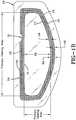
- the kitincludes an optical insert 12 and a border attachment element 14.
- Fig. 1Ashows the separate elements of the kit as well as the viewing lens 10 of an eye-shielding device before assembly.
- Fig. 1Bshows the different elements after they have been assembled and attached to the viewing lens 10.
- the optical insert 12has an outer perimeter 16.
- the border attachment element 14has an outer periphery 15 and an inner periphery 17. At least a portion of the outer periphery 15 extends outside the outer perimeter 16, defining an "outer periphery area" 18. At least a portion of the inner periphery 17 extends inward of the outer perimeter 16 of the optical insert 12.
- the area between the optical element's outer perimeter 16 and the border attachment element's inner periphery 17forms an "inner periphery area" 19.
- the inner periphery area 19covers part of the optical insert 12 to define a primary viewing area 30.
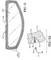
- the border attachment element 14has a first adhesive area 20 for attachment to the optical insert 12 and a second adhesive area 22 for attachment to the viewing lens.
- the border attachment element 14When attached, the border attachment element 14 defines a buffer zone 24 which spans the outer periphery area 18 (i.e. the portion of the outer periphery that extends beyond the outer perimeter 16 of the optical insert 12) and the inner periphery area 19 (i.e. the portion of the outer periphery that extends inward of the outer perimeter 16).
- the buffer zonemay surround only a portion of the primary viewing area, or, alternatively, may surround the entire primary viewing area (as shown in fig. 1B ).
- the buffer zonemay be clear, tinted, colored, or include a pattern on at least a portion of its surface.
- optical insertsconfigured to be attached to helmet visors or similar viewing lenses needed to have a gasket or peripheral foam or adhesive material for attachment to the visor to create a moisture barrier.
- This "gasket”often provided an opaque or optically unclear border area around the optical insert. (see fig. 2C ).
- Other optical insert designsemployed mechanical means for attachment to a helmet visor, again resulting in unsightly attachment means that could be seen by the wearer or a viewer looking at the visor from the outside.
- using a border attachment element as described aboveremoves the necessity for providing such a gasket, foam or border zone around the optical insert or providing attachment means directly on the optical insert.
- the optical insert of the present inventionmay be provided with or without a gasket.
- the buffer zonemay be clear so that the user sees no abrupt "border" around the optical insert.
- the buffer zone 24may include a pattern of opaque elements sized and spaced to provide a light filtering effect in at least a portion of the buffer zone.
- the opaque elementsmay be any pattern or color.
- the patternincludes an opaque mesh pattern of repeating shapes (such as squares, triangles, circles, hexagons, etc.) having a "clear to opaque material" ratio of 10:90, 20:80, 30:70, 40:60, 50:50, 60:40, 70:30, 80:20, 90:10 or any size in between.
- the clear to opaque ratiois from 50:50 to 70:30, or any size in between.
- the patternis made of clear circular holes surrounded by opaque material. See Fig.
- Other patternscan also be provided in any color, and in any configurations, e.g. to display images, logos, etc. as desired by the end-user.
- the patterns or the colormay be only on the outside surface of the border attachment element, i.e. so it is visible only from the outside.
- the patterns / colormay be on the inside surface (visible to the user) or on both surfaces (visible both to the user and an outside viewer).
- the border attachment elementis made of a flexible material which, in some examples, may be capable of stretching in one or more dimensions for better conformance to a curved surface of the viewing lens.
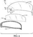
- the border attachment element 14includes a perforated area or sheet.
- the perforated area or sheetwhich may be made of any flexible plastic, can have an array of perforations sized and arranged to permit further stretching of the perforated area in two dimensions to permit attachment of a flat optical insert to a visor with different curvatures. This stretching may also make it possible to adhere a flexible but flat optical insert 12 to a visor's viewing area when the visor is curved in one or more dimensions.
- the pattern of perforationsincludes a mesh pattern of repeating shapes (such as squares, triangles, circles, hexagons, etc.) having a "hole to solid material" ratio of 10:90, 20:80, 30:70, 40:60, 50:50, 60:40, 70:30, 80:20, 90:10 or any size in between.
- the hole to solid ratiois from 5:50 to 70:30, or any size in between.
- the "holes"are circular. See Fig. 3 .
- the mesh screenmay have any color, including a clear color, white (or opaque), black, or any color chosen by the user.
- Adhesion of the optical insert 12 to the border attachment element 14may be achieved in two ways, as shown in Fig. 2.
- Fig 2Ashows an arrangement where the first adhesive area 20 is used to attach to the inside surface of the optical insert 12 and the second adhesive area 22 is used to attach to the inside surface of the viewing lens 10.
- border attachment element 14forms a "ramp" between the optical insert 12 and the viewing lens 10.
- This "ramp”has the advantage of protecting the optical insert 12 and its edges from being bumped, dislodged or detached, for example if a helmet gasket around the viewing area of an eye-shielding device, or another object, accidentally hits against the outer perimeter of the optical insert.
- the ramped areawhen provided on the upper and lower edges of the optical insert 12 on a motorcycle helmet, helps prevent abrasion of the edges of the optical insert by the helmet gasket when pivoting the helmet visor 10 between raised and lowered positions.
- the ramped areaguides the gasket over the optical insert 12 and prevents direct engagement with the edge of the optical insert.
- the rampcan simplify handling the assembled optical insert - viewing lens and inserting in into the frame of the goggle without the frame hitting or bumping the edge of the optical insert.
- the figuresare not to scale, and so for example, the border attachment element 14, which forms the ramp in Fig. 2 , may be much thinner than the optical insert 12.
- the "ramp" feature formed by the border attachment elementtherefore, simplifies the assembling and attachment of the optical insert to the viewing lens, and protects the edges of the optical insert against being hit or bumped or displaced.
- Another advantage of the border attachment elementis that it is no longer necessary to provide a foam or gasket around the inside surface of the optical insert (see Fig 2C showing a prior art optical insert attached by means of a gasket or foam 50 to the viewing lens 10).
- Fig. 2Bshows another arrangement, not forming part of the claimed invention, where the optical insert 12 and border attachment element 14 are attached to the outside surface of the viewing lens 10 of an eye shielding device.
- optical insert 12is attached to a first adhesive area 120 and viewing lens 10 is attached to a second adhesive area 122.
- This arrangementcan also make advantageous use of the "ramp" formed by the border attachment element 14, for example, if the assembled viewing lens and the optical insert need to be placed inside a frame, etc. (e.g. of a goggle).
- a uniform adhesive coatingmay be provided on the first and second adhesive areas so as to provide permanent attachment to the optical insert 12 and the viewing lens 10.
- the adhesive coating on the first and second adhesive areasmay be configured to detachably attach to the optical insert 12 and the viewing lens 10.
- the type of adhesive provided on the first and second adhesive areasmay be different, so that one provides a permanent attachment while the other provides a detachable attachment, or vice versa.
- the adhesivesmay be configured to provide a substantially permanent attachment of the border attachment element 14 to the optical insert 12, and a substantially detachable attachment of the border attachment element 14 to the viewing lens 10, allowing for removal, replacement, and/or repositioning of the optical insert-border attachment element assembly on the viewing lens or onto another viewing lens or device.
- the optical insertitself may be detachably attached to the border attachment element.
- different border attachment elementsmay be used with the same optical insert, e.g. for different conditions or as desired by fashion, etc.
- the kitmay include a pre-assembled (pre-adhered) optical insert and border attachment element so the end user would only be required to attach the pre-assembled element to the viewing lens.
- detachable attachmentis defined as an attachment that nevertheless enables the end user to detach the objects if desired. Accordingly, an optical insert that is detachably attached may be removed by the end user without causing damage to the visor or to the optical insert. In contrast, “permanently attached” optical inserts or border attachment elements are not meant to be removed by the end user once they have been attached because such removal may cause damage to the viewing lens or the optical insert.
- the border attachment elementcan be clear, tinted or colored (e.g., to match the frame or helmet shell).
- the border attachment elementmay have an area that is printed with a pattern, shape, image, logo, or any desirable design "printed" on its outside surface, its inside surface, or both.
- the non-adhesive area of border attachment element 14may be provided in a dark color (e.g. grey or black) to provide a shading effect through the buffer zone area.
- the adhesive area of the border attachment elementmay be a similar color, or may be provided in other colors, or printed in a variety of suitable or desirable patterns, logos, or images.
- the optical insetis an anti-fog, anti-glare, polarizer or a tinted insert.
- the optical insetis a flexible light attenuating element.
- Light attenuating elementsinclude any element where the element can change tint in response to light (e.g. photochromic) or an external stimulus (e.g. voltage or current). Examples of light attenuating elements include photochromic, electro-chromic, or liquid crystal elements, or the like.
- An exemplary optical insertincludes an electronically controllable variable light-attenuating liquid crystal cell that uses a guest-host solution comprising a host material and a light-absorbing dichroic dye guest.
- a guest-host solutioncomprising a host material and a light-absorbing dichroic dye guest.
- One such liquid crystal cellis described in detail in U.S. Patent No. 6,239,778 (Taheri et al. ).
- the liquid crystal cellselectively or automatically adjusts light absorption of the optical insert. Electrical signals delivered to the liquid crystal cell alter the orientation of a light attenuating dichroic dye dispersed in the liquid crystal cell, thereby altering the light attenuation or absorption of the liquid crystal cell.
- the light attenuating elementincludes a controller electrically connected to the liquid crystal cell and configured to selectively supply a voltage across the liquid crystal cell.
- the liquid crystal cellincludes spaced apart, opposed substrates forming a gap which contains a mixture of a liquid crystal or other electro-optic material host material (such as an electro-chromic or photochromic-dichroic material) and a guest dichroic dye material.
- the substratesmay contain transparent electrode layers, which may be formed from indium tin oxide, conductive polymer or other appropriate conductive material, to allow for application of a voltage across a gap between the substrates.
- the material used for the substratesis a flexible plastic material.
- an alignment layermay be disposed on each electrode layer or just one of the electrode layers. The alignment layers can align the liquid crystal molecules adjacent to the alignment layers, wherein the molecules are part of the liquid crystal material received between the substrates.
- the gap between the substratesis maintained by spacers, as is commonly known in the art.
- the substrates, through their electrode layers,are connected to a controller (90) which typically includes a drive circuit, a power source and an activator or activation circuit.
- the control circuitapplies a voltage and/or voltage waveform in an appropriate manner to change the orientation of the liquid crystal material.
- various optical propertiese.g., absorption, no absorption, high transmission, low transmission, and states in between
- the variable light-attenuating liquid crystal cell described hereincan change tint, i.e. go from a "clear" state, where the optical element allows the maximum amount of light through, to a "tinted” state, where the optical element allows the minimal amount of light through, or in any state between the fully clear or fully tinted states.
- the absorptioncan be broad-band (i.e. absorbing across the entire visible spectrum) or across a selected band or region of the visible light spectrum.
- the optical elementmay provide protection against UV light.
- the variable light-attenuating liquid crystal cell used in some embodiments of the optical elementis configured so that it is "fail-safe", i.e. it reverts to the clear state when there is no voltage applied across the liquid crystal cell.
- the variable light-attenuating liquid crystal celldoes not employ polarizers.
- the optical elementmay contain a photochromic-dichroic cell, containing a light-sensitive mixture comprising a fluid material and a photochromic dyestuff material, and a medium for carrying the mixture, wherein the mixture varies between a first condition and a second condition, the first condition letting substantially all light to pass through the mixture, and the second condition absorbing light passing through the mixture.
- a fluidsuch as a liquid crystal
- photochromic dyestuff materialis described in greater detail in U.S. Patent No. 6,999,220 (Kosa et al. ), Device Exhibiting Photo-Induced Dichroism For Adaptive Anti-Glare Vision Protection. Such a mixture will exhibit photo-induced dichroism.
- the flexible light attenuating elementincludes an electronically controlled liquid crystal cell and a controller electrically connected to the liquid crystal cell and configured to selectively supply a voltage across the liquid crystal cell.
- the controlleris an integral part of the optical insert while in other embodiments; the controller may be a separate device.
- the kit or optical insert assemblymay include the separate controller device, that can be attached to the viewing lens or the eye-shielding device itself (e.g. its frame, helmet shell, etc.).
- the controllermay be operated automatically, semi-automatically, or exclusively by user input (manually or by a remote control device), or any combination of the above (e.g. have both an automatic and a manual mode, etc.).
- the activation devicemay be part of the controller device, or a separate device. Accordingly, the kit or optical insert assembly may further include a manually operable activation device electrically or remotely connected with the controller for selectively adjusting the voltage across the liquid crystal cell.
- connection between the optical element substrates (or electrodes) and a controllermay be achieved in a variety of ways known in the art.
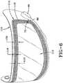
- a viewing lens 110an electronically controlled light attenuating element 112 and its electronic connection through the border attachment element 114.
- the border attachment element 114has a slit or opening 70 through which an inter-connection tab 72 can pass through and protrude.
- the interconnection tab 72contains a conductive via 74 which connects the electrode layers of the optical element 112 to a plug 84.
- the plug 84mates with a socket 86, which is connected through a wire 88 with the controller 90.
- Alternative connection elements other than a wirecan also be used, such as a flexible via, etc.
- a disconnectable arrangementwhich may be utilized, for example, to facilitate replacement of only one of the light attenuating element 112 and the controller 90, or to enable storage as separate components.
- a controllermay be connected to the light attenuating element with leads on the drive circuit connected directly to the conductive tabs of the light attenuating element. This may also facilitate attachment of the controller to the eye-shielding device.
- the wired connection 88may be secured to the inner surface of the visor.
- the controller 90can be secured to an outer surface of the visor 110, and the wired connection 88 may be extended over an outer edge (e.g., a lower edge, as shown in Fig. 5 ) of the visor 110, or may go through a hole in the visor.
- controller 90is provided with an adhesive pad 92 for attachment to a surface of the helmet visor 110.
- Figure 6shows the arrangement of Fig. 5 as it appears to an outside viewer (i.e. viewed through the viewing lens 110). It also shows the outer periphery area 118, the inner periphery area 119, and the buffer zone 124 as viewed from the outside.
- the controlleris activated manually, so the optical element assembly or the kit further include a manually operable activation device electrically (or remotely) connected with the controller for selectively adjusting the voltage across the liquid crystal cell.
- the activation device or controllermay be operated automatically, semi-automatically, or by a combination of the above.
- a viewing lens 210is shown together with an optical element or insert 212 and a border attachment element 214.
- the optical element 212includes a controller 290.
- the controller 290is an integral part of the optical element.
- the controllermay be operated automatically, for example where the controller includes an automatic activating device for automatically controlling the amount of voltage applied to the optical element using a photoreceptor/photovoltaic cell configured to provide a voltage proportional to the amount of light impinging on the photoreceptor or where a photoreceptor is configured to provide a signal indicating the amount of light (e.g.
- controller 290may be operated, activated, or the voltage or other criteria adjusted via a remote control or other wireless devices.
- the inventionrelates to one or more kits that comprise the various elements described herein, including the light attenuating element, the controller, the power source, the means for attaching the optical element, the controller or both, to the viewing lens and/ or the eye-shielding device, and, in some cases, a remote control device, and/or an adapter or inverter for recharging the power source (e.g., a USB or similar port and means for connecting it to an outside power source such as a wall socket or car charger).
- the power sourcee.g., a USB or similar port and means for connecting it to an outside power source such as a wall socket or car charger.
- kits and examplesas described above, but do not form part of the claimed invention.
- a method for attaching an optical insert to a viewing lens of an eye-shielding deviceincludes: providing a viewing lens (10, 110, 210) of an eye-shielding device, providing an optical insert (12, 120, 212) having an outer perimeter (16, 116); providing a border attachment element (14, 114, 214) having an inner periphery area (19, 119) and an outer periphery area (18, 118), as described above, the border attachment element comprising a first adhesive area (20, 120) for attachment to the optical insert and a second adhesive area (22, 122) for attachment to the viewing lens.
- the method stepsinclude adhering the first adhesive area to the optical insert; and adhering the second adhesive area to the viewing lens of the eye-shielding device so as to create a buffer zone (24, 124) spanning the inner periphery area and the portion of the outer periphery area, as described above.
- Adhering the first adhesive areas to the optical insertmay include permanently adhering or detachably adhering.
- adhering the second adhesive area to the viewing lensmay include permanent adhesion or detachable adhesion.
- the optical insert and the viewing lensmay be either permanently attached or detachably attached, depending on the type of adhesive provided on the first and second adhesive areas.
- adhering the second adhesive area to the viewing lensmay include stretching the border attachment element around a first axis bisecting a width of the optical insert and around a second axis perpendicular to the first axis and bisecting a height of the optical insert, such that the outer periphery of the adhesive area conforms to a curved viewing lens having multiple axes of curvature, or having a different curvature than the optical insert.
- the methodmay further include securing to the viewing lens or the eye-shielding device or its frame, etc., a controller and/or a manually operable activation device electrically connected with the liquid crystal cell for selectively adjusting the voltage across the liquid crystal cell.
- an electronically controlled light attenuating devicesuch as a liquid crystal cell
- the optical insert assemblywill include the controller (separate or integrated with the optical insert), and/or an activation device, etc., as described above.
Landscapes
- Health & Medical Sciences (AREA)
- Ophthalmology & Optometry (AREA)
- General Health & Medical Sciences (AREA)
- Physics & Mathematics (AREA)
- Life Sciences & Earth Sciences (AREA)
- Vascular Medicine (AREA)
- Heart & Thoracic Surgery (AREA)
- Animal Behavior & Ethology (AREA)
- Biomedical Technology (AREA)
- Public Health (AREA)
- Veterinary Medicine (AREA)
- Engineering & Computer Science (AREA)
- General Physics & Mathematics (AREA)
- Optics & Photonics (AREA)
- Helmets And Other Head Coverings (AREA)
Description
- The present invention is directed to optical elements and their methods of assembly. Specifically, the present invention is directed to visors, goggles and other eye-shielding devices, and how optical elements are attached or otherwise secured to those devices.
- Protective and performance enhancing helmet visors, goggles, and other such eye-shielding devices often provide protection for a wearer's eyes while maintaining or enhancing optical functionality for the wearer, for example, by magnifying, clarifying, darkening, tinting, or lightening ("bleaching") light transmission through the device. In many applications, such as motorcycle helmets, the eye-shielding device such as a visor is configured to match an opening in the helmet for the visor. In particular, the visor and helmet are designed to allow the user to seamlessly pivot the visor up or down. To avoid water penetration between the visor and helmet, the helmet is typically equipped with an elastic gasket which presses against the visor to create a tight seal. To enhance the capability of an eye-shielding device in a variety of conditions, including, for example, fog, condensation, sun glare, or darkness, an enhancing secondary lens (insert) can be used.
- While the insert lens may be integrated into an eye-shielding device, in some instances, the insert may be provided as a separate attachment for assembly with or installation on an existing eye-shielding device, for example, for after-market or end user installation.
- Typically, an optical insert is configured to fit various sizes and shapes of helmet visors. However, addition or presence of an insert presents several limitations. First, if a flat (non-curved or two-dimensional) optical insert is used, it may not fit a double or multiple curved viewing lens of an eye-shielding device, thus limiting the use of such an optical insert. Second, an insert will create a thickness variation which can significantly hinder the operation of the helmet gasket. In other words, if the insert is large, it can interfere with the sealing properties between the visor and the helmet gasket. On the other hand, if it is smaller than the visor, it may interfere with seamless movement of the visor. For example, the insert may catch the gasket as the user tries to pivot the visor up above the opening. To avoid this, the insert must be sized such that it can fit within the clearance created between the gasket and the visor as the visor is pivoted up. However, this sizing limitation can result in light leakage between the visor insert and the gasket, which can be highly undesirable. This issue has not been addressed with current inserts. Current inserts use either foam or a mechanical clip to hold the insert in place. And to avoid the interference with the gasket, the insert is typically much smaller than the visor.
- Thus, it is desirable to have an attachment mechanism that can allow attachment of an optical insert without the limitation associated with the curvature of the visor or the gasket of the helmet, or both.
US 2011/283431 A1 discloses an optical arrangement as part of an eye-shielding device comprising means for attaching an outer periphery of an optical element to a surface of a viewing lens of the eye-shielding device.- Disclosed herein are optical insert assemblies, kits, and methods for attaching an optical insert to a viewing lens of an eye-shielding device.
- The kit includes: an optical insert with an outer perimeter, and a flexible border attachment element with an inner and outer periphery, sized such that: at least a portion of its inner periphery extends inward of the outer perimeter of the flexible optical insert defining an "inner periphery area", and at least a portion of its outer periphery extends outward of the outer perimeter of the flexible optical insert defining an "outer periphery area". The border attachment element has a first adhesive area for attachment to the optical insert and a second adhesive area for attachment to the viewing lens of the face shielding device. When attached, the border attachment element defines a buffer zone spanning the border attachment element's inner periphery area (i.e. the portion of its inner periphery that extends inward and covers the optical insert), and outer periphery area (i.e. the portion of its outer periphery that extends beyond the outer perimeter of the optical insert).
- The optical insert assembly includes all the elements of the kits described herein, attached to a viewing lens of an eye-shielding device.
- The buffer zone may surround only a portion of the outer perimeter of the optical insert or, alternatively, may surround the entire outer perimeter of the optical insert.
- The border attachment element is made of a flexible material which, in some examples, may be capable of stretching in one or more dimensions for better conformance to a curved surface of the viewing lens. The border attachment element can be clear, tinted or colored. In some embodiments, the border attachment element may have an area that is printed with a pattern, shape, logo, or any desirable design "printed" on its outside area, its inside area, or both.
- In some embodiments, the border attachment element includes a perforated area or is made of a perforated sheet.
- In some embodiments, the perforated area or sheet contains an array of perforated shapes (e.g. circles, triangles, squares, hexagons, etc.) that forms a "mesh screen" having a "hole to solid material" ratio of from 10:90, 20:80, 30:70, 40:60, 50:50, 60:40, 70:30, 80:20, 90:10 or any size in between. Preferably the hole to solid ratio is from 50:50 to 70:30, or any size in between. In some embodiments, at least a portion of the buffer zone comprises a pattern of opaque elements (e.g. circles, triangles, squares, hexagons, etc.) sized and spaced to provide a light filtering effect in the buffer zone.
- In some examples, the pattern of the opaque elements form a mesh screen having a clear to opaque ratio of from 10:90, 20:80, 30:70, 40:60, 50:50, 60:40, 70:30, 80:20, 90:10 or any size in between. Preferably the clear to opaque ratio is from 50:50 to 70:30, or any size in between.
- When the optical insert is secured to the inner surface of the viewing lens of an eye-shielding device by the border attachment element, the non-adhesive surface of the border attachment element in the buffer zone forms a ramped area between the inner surface of the optical insert and the inner surface of the viewing lens. This ramped area reduces interference between the insert and/or its edge and a device frame or gasket (e.g. a goggle frame or a helmet gasket).
- In some embodiments, the border attachment has a thickness less than that of the optical insert such that it does not interfere with a helmet gasket during the movement of the visor.
- The eye-shielding device is any device with a clear viewing area worn to protect the eyes. In some example, the eye-shielding device is a helmet visor, or goggle (e.g. sports goggle, ski goggle, paintball goggle, etc).
- The optical insert may be any flexible plastic insert that can be attached to the viewing area of an eye-shielding device and which can alter or enhance the performance or optical properties of the eye-shielding device by providing an added function, e.g. an anti-fog function, a tinting function, a light-attenuating function (e.g. a photochromic, electrochromic or liquid crystal light attenuating device or the like), an anti-glare function, a decorative function, or a combination of any of the above, or any beneficial function.
- The first and/or second adhesive areas of the border attachment element may comprise a permanent adhesive, or an adhesive configured for detachable attachment of the border attachment element to the optical insert, or the viewing lens, or both. For example, the adhesive areas may be configured so that the optical insert may be permanently attached to first adhesive area, but the second adhesive area may be detachably attached to the viewing lens. In other embodiments, the first and second adhesive areas may be configured so as to provide permanent attachment to the optical insert, the viewing lens or to both.
- Also contemplated herein are various configurations for attachment of the border attachment element to the optical insert and viewing lens so that the first and second adhesive areas may be on the same surface, or on opposite surfaces from each other.
- In some embodiments, the optical insert includes a flexible light attenuating element. Such an element may be "active" (i.e. need a voltage applied to it to operate), such as a liquid crystal or electrochromic device. In some examples, the element may be "passive" (i.e. operate without the requirement for a voltage), such as a photochromic device or the like.
- In some embodiments, the flexible light attenuating element includes an electronically controlled liquid crystal cell and a controller electrically connected to the liquid crystal cell and configured to selectively supply a voltage across the liquid crystal cell. In some embodiments, the controller is an integral part of the optical insert while in other embodiments; the controller may be a separate device. In the latter case, the kit or optical insert assembly may include the separate controller device, that can be attached to the viewing lens or the eye-shielding device itself (e.g. its frame, helmet shell, etc.).
- The controller may be operated automatically, semi-automatically, or exclusively by user input (manually or by a remote control device), or any combination of the above (e.g. have both an automatic and a manual mode, etc.). The activation device may be part of the controller device, or a separate device. Accordingly, the kit or optical insert assembly may further include a manually operable activation device electrically or remotely connected with the controller for selectively adjusting the voltage across the liquid crystal cell.
- In some embodiments, the optical insert may include a protective film for improved structural integrity (e.g. to add strength) or ease of handling of the optical insert.
- Also provided herein are methods for attaching an optical insert to a viewing lens of an eye-shielding device. The method, which does not form part of the claimed invention, includes providing a viewing lens; providing an optical insert having an outer perimeter; providing a border attachment element having an inner periphery area and an outer periphery area as described above, the border attachment element having a first adhesive area for attachment to the optical insert and a second adhesive area for attachment to the viewing lens. The method further includes adhering the first adhesive area to the optical insert and/or adhering the second adhesive area to the viewing lens so as to create a buffer zone spanning the inner periphery area and the outer periphery area.
- In some embodiments of the method, the optical insert and the border attachment element may have been pre-adhered, so that the end user would only need to attach the pre-adhered assembly to the viewing lens.
- The methods described herein use the kits and examples enumerated above and result in the optical insert assemblies described herein. Therefore, all the elements recited for the optical insert assemblies, kits and methods are interchangeable.
- For example, where the optical insert assembly or kit includes an electronically controlled light attenuating device (such as a liquid crystal cell), the method may further include securing to the viewing lens, or the eye-shielding device, its frame, helmet, etc., a controller and/or an activation device electrically connected with the liquid crystal cell for selectively adjusting the voltage across the liquid crystal cell, as described above
- In some embodiments, the method includes detachably adhering the second adhesive area to the eye-shielding device, so that the optical insert may be removed when not needed, or for replacement or repair purposes, etc. In such cases, the optical insert may be permanently adhered to the border attachment element, so that by separating the border attachment element from the viewing lens, the optical insert will also be removed. In other instances, the optical insert itself may be detachably attached to the border attachment element. In this example, different border attachment elements may be used with the same optical insert, e.g. for different conditions or as desired by fashion, etc. In other embodiments, the first and second adhesive areas may be configured so as to provide permanent attachment to the optical insert, the eye-shielding device or to both.
- In some examples, where the border attachment element includes a perforated sheet or area or is flexible such that it can be stretched, adhering the border attachment element to the viewing lens may involve stretching the border attachment element for better conformity to the shape of the viewing lens and therefore better attachment. For example, when attaching the optical insert to a curved helmet visor, the border attachment element may be stretched around a first axis bisecting a width of the perforated area and around a second axis perpendicular to the first axis and bisecting a height of the perforated area, such that the outer periphery of the adhesive area conforms to the viewing lens or visor having one or more axes of curvature. In this way, a flat optical insert may be successfully attached to a viewing area of an eye-shielding device that is curved, even when it is curved in more than one dimension (double- or multiple-curved lens).
- Features and advantages of the invention will become apparent from the following detailed description made with reference to the accompanying drawings, wherein:
Fig. 1A is an exploded, perspective schematic diagram of a viewing lens, an optical insert and a border attachment element according to the invention.Fig. 1B is an elevational view, partially broken away, of the assembled optical insert, border attachment element and viewing lens as described herein;Fig. 2A shows a cross-sectional schematic of the assembled optical insert and attachment element according to the invention.Fig. 2B shows a cross-sectional schematic of an assembly not forming part of the claimed invention.Fig. 2C shows a prior art cross-sectional schematic example of an optical insert attached to a viewing lens;Fig. 3 is an elevational view of a border attachment element having an opening for protrusion of an interconnection tab through it, which is shown in the detailed view ofFig. 3A ;Fig. 4 is an inside perspective view of a helmet visor, a border attachment element, and an electronically controlled light attenuating optical insert and a separate controller, shown with the optical insert and border attachment element separated from the helmet visor;Fig. 5 is an inside perspective view of the border attachment element and optical insert ofFig. 4 attached to the helmet visor and controller;Fig. 6 is an outside perspective view of the optical insert assembly ofFig. 5 ; andFig. 7 is an exploded, perspective view of a helmet visor, a border attachment element, and an electronically controlled light attenuating optical insert with an integrated controller, shown with the optical insert and border attachment element separated from the helmet visor.- The structures shown schematically in the drawings have parts that are examples of the elements recited in the apparatus claims. The illustrated structures thus include examples of how a person of ordinary skill in the art can make and use the claimed invention. It is described here to meet the enablement and written description requirements of the patent statute without imposing limitations that are not recited in the claims.
- The present application contemplates optical insert assemblies, kits and methods for attaching an optical insert to a viewing lens of an eye-shielding device. The eye-shielding device is any device with a clear viewing area worn to protect the eyes. Examples include a protective helmet visor (e.g. for sports, racing, motorcycle, paintball helmets, etc), or protective goggles (e.g. ski or other sports goggles, etc) and the like.
- The optical insert may be any flexible plastic insert that can be attached to the viewing area of an eye-shielding device and which can alter or enhance the performance of the eye-shielding device by providing an added function, e.g. an anti-fog function, a tinting function, a light-attenuating function (e.g. a photochromic, electrochromic or liquid crystal light attenuating device or the like), an anti-glare function, a polarizing function, a UV protection function, or a combination of any of the above.
- According to one aspect of the invention, a kit is provided for assembly with the viewing lens of an eye-shielding device (such as a helmet visor, or goggle). Such a kit may be manufactured as an after-market product for assembly by a retailer or an end user.
- As shown in
Figs. 1 and2 , the kit includes anoptical insert 12 and aborder attachment element 14.Fig. 1A shows the separate elements of the kit as well as theviewing lens 10 of an eye-shielding device before assembly.Fig. 1B shows the different elements after they have been assembled and attached to theviewing lens 10. Theoptical insert 12 has anouter perimeter 16. Theborder attachment element 14 has anouter periphery 15 and aninner periphery 17. At least a portion of theouter periphery 15 extends outside theouter perimeter 16, defining an "outer periphery area" 18. At least a portion of theinner periphery 17 extends inward of theouter perimeter 16 of theoptical insert 12. The area between the optical element'souter perimeter 16 and the border attachment element'sinner periphery 17 forms an "inner periphery area" 19. Theinner periphery area 19 covers part of theoptical insert 12 to define aprimary viewing area 30. - In one embodiment, shown in
Fig 2A , theborder attachment element 14 has a firstadhesive area 20 for attachment to theoptical insert 12 and a secondadhesive area 22 for attachment to the viewing lens. - When attached, the
border attachment element 14 defines abuffer zone 24 which spans the outer periphery area 18 (i.e. the portion of the outer periphery that extends beyond theouter perimeter 16 of the optical insert 12) and the inner periphery area 19 (i.e. the portion of the outer periphery that extends inward of the outer perimeter 16). The buffer zone may surround only a portion of the primary viewing area, or, alternatively, may surround the entire primary viewing area (as shown infig. 1B ). The buffer zone may be clear, tinted, colored, or include a pattern on at least a portion of its surface. - Traditionally, optical inserts configured to be attached to helmet visors or similar viewing lenses needed to have a gasket or peripheral foam or adhesive material for attachment to the visor to create a moisture barrier. This "gasket" often provided an opaque or optically unclear border area around the optical insert. (see
fig. 2C ). Other optical insert designs employed mechanical means for attachment to a helmet visor, again resulting in unsightly attachment means that could be seen by the wearer or a viewer looking at the visor from the outside. However, using a border attachment element as described above removes the necessity for providing such a gasket, foam or border zone around the optical insert or providing attachment means directly on the optical insert. Although such a gasket or foam may be employed, it is not necessary and the optical insert can be configured to function without such a peripheral gasket or foam. Thus, the optical insert of the present invention may be provided with or without a gasket. In some examples, the buffer zone may be clear so that the user sees no abrupt "border" around the optical insert. - However, in some embodiments, at least a portion of the
buffer zone 24 may include a pattern of opaque elements sized and spaced to provide a light filtering effect in at least a portion of the buffer zone. The opaque elements may be any pattern or color. In some examples, the pattern includes an opaque mesh pattern of repeating shapes (such as squares, triangles, circles, hexagons, etc.) having a "clear to opaque material" ratio of 10:90, 20:80, 30:70, 40:60, 50:50, 60:40, 70:30, 80:20, 90:10 or any size in between. Preferably the clear to opaque ratio is from 50:50 to 70:30, or any size in between. In some examples, the pattern is made of clear circular holes surrounded by opaque material. SeeFig. 3 . Other patterns can also be provided in any color, and in any configurations, e.g. to display images, logos, etc. as desired by the end-user. In some examples, the patterns or the color may be only on the outside surface of the border attachment element, i.e. so it is visible only from the outside. In other examples, the patterns / color may be on the inside surface (visible to the user) or on both surfaces (visible both to the user and an outside viewer). - The border attachment element is made of a flexible material which, in some examples, may be capable of stretching in one or more dimensions for better conformance to a curved surface of the viewing lens.
- In some embodiments, the
border attachment element 14 includes a perforated area or sheet. The perforated area or sheet, which may be made of any flexible plastic, can have an array of perforations sized and arranged to permit further stretching of the perforated area in two dimensions to permit attachment of a flat optical insert to a visor with different curvatures. This stretching may also make it possible to adhere a flexible but flatoptical insert 12 to a visor's viewing area when the visor is curved in one or more dimensions. - In some examples, the pattern of perforations includes a mesh pattern of repeating shapes (such as squares, triangles, circles, hexagons, etc.) having a "hole to solid material" ratio of 10:90, 20:80, 30:70, 40:60, 50:50, 60:40, 70:30, 80:20, 90:10 or any size in between. Preferably the hole to solid ratio is from 5:50 to 70:30, or any size in between. In some examples, the "holes" are circular. See
Fig. 3 . The mesh screen may have any color, including a clear color, white (or opaque), black, or any color chosen by the user. - Adhesion of the
optical insert 12 to theborder attachment element 14 may be achieved in two ways, as shown inFig. 2. Fig 2A shows an arrangement where the firstadhesive area 20 is used to attach to the inside surface of theoptical insert 12 and the secondadhesive area 22 is used to attach to the inside surface of theviewing lens 10. In this arrangement,border attachment element 14 forms a "ramp" between theoptical insert 12 and theviewing lens 10. This "ramp" has the advantage of protecting theoptical insert 12 and its edges from being bumped, dislodged or detached, for example if a helmet gasket around the viewing area of an eye-shielding device, or another object, accidentally hits against the outer perimeter of the optical insert. This is particularly useful where the optical insert is attached to a helmet visor or the like, where the visor moves (e.g. pivots up and down) in relation to the remainder of the helmet. For example, the ramped area, when provided on the upper and lower edges of theoptical insert 12 on a motorcycle helmet, helps prevent abrasion of the edges of the optical insert by the helmet gasket when pivoting thehelmet visor 10 between raised and lowered positions. When pivoting the helmet visor, the ramped area guides the gasket over theoptical insert 12 and prevents direct engagement with the edge of the optical insert. In other embodiments, for example if the eye-shielding device is a goggle, the ramp can simplify handling the assembled optical insert - viewing lens and inserting in into the frame of the goggle without the frame hitting or bumping the edge of the optical insert. It should be noted that the figures are not to scale, and so for example, theborder attachment element 14, which forms the ramp inFig. 2 , may be much thinner than theoptical insert 12. - The "ramp" feature formed by the border attachment element, therefore, simplifies the assembling and attachment of the optical insert to the viewing lens, and protects the edges of the optical insert against being hit or bumped or displaced. Another advantage of the border attachment element is that it is no longer necessary to provide a foam or gasket around the inside surface of the optical insert (see
Fig 2C showing a prior art optical insert attached by means of a gasket orfoam 50 to the viewing lens 10). - Another problem inherent in traditional models, where a gasket around the optical insert was used for attachment to the viewing lens (
Fig 2C ), was that when a flat optical insert was flexed or bent to conform to a curved viewing lens, the gasket, which has a considerable thickness, as compared to the optical insert, would become strained or would "wrinkle", resulting in inferior attachment, or aesthetics, or both. The flexible border attachment element of the present invention circumvents that problem by eliminating, in some example, the need for the traditional gasket, and by being considerably more flexible than traditional gaskets, enhancing the aesthetics and the attachment quality. Fig. 2B shows another arrangement, not forming part of the claimed invention, where theoptical insert 12 andborder attachment element 14 are attached to the outside surface of theviewing lens 10 of an eye shielding device. In this arrangement,optical insert 12 is attached to a firstadhesive area 120 andviewing lens 10 is attached to a secondadhesive area 122. This arrangement can also make advantageous use of the "ramp" formed by theborder attachment element 14, for example, if the assembled viewing lens and the optical insert need to be placed inside a frame, etc. (e.g. of a goggle).- In any of the embodiments described above (
Fig. 2A-B ), a uniform adhesive coating may be provided on the first and second adhesive areas so as to provide permanent attachment to theoptical insert 12 and theviewing lens 10. Alternatively, the adhesive coating on the first and second adhesive areas may be configured to detachably attach to theoptical insert 12 and theviewing lens 10. - Alternatively, the type of adhesive provided on the first and second adhesive areas may be different, so that one provides a permanent attachment while the other provides a detachable attachment, or vice versa. For example, the adhesives may be configured to provide a substantially permanent attachment of the
border attachment element 14 to theoptical insert 12, and a substantially detachable attachment of theborder attachment element 14 to theviewing lens 10, allowing for removal, replacement, and/or repositioning of the optical insert-border attachment element assembly on the viewing lens or onto another viewing lens or device. - In other instances, the optical insert itself may be detachably attached to the border attachment element. In this example, different border attachment elements may be used with the same optical insert, e.g. for different conditions or as desired by fashion, etc.
- In some embodiments, the kit may include a pre-assembled (pre-adhered) optical insert and border attachment element so the end user would only be required to attach the pre-assembled element to the viewing lens.
- The term "detachable attachment" is defined as an attachment that nevertheless enables the end user to detach the objects if desired. Accordingly, an optical insert that is detachably attached may be removed by the end user without causing damage to the visor or to the optical insert. In contrast, "permanently attached" optical inserts or border attachment elements are not meant to be removed by the end user once they have been attached because such removal may cause damage to the viewing lens or the optical insert.
- In any of the above described embodiments, the border attachment element can be clear, tinted or colored (e.g., to match the frame or helmet shell). In some embodiments, the border attachment element may have an area that is printed with a pattern, shape, image, logo, or any desirable design "printed" on its outside surface, its inside surface, or both. For example the non-adhesive area of
border attachment element 14 may be provided in a dark color (e.g. grey or black) to provide a shading effect through the buffer zone area. The adhesive area of the border attachment element may be a similar color, or may be provided in other colors, or printed in a variety of suitable or desirable patterns, logos, or images. - In some embodiments, the optical inset is an anti-fog, anti-glare, polarizer or a tinted insert.
- In some embodiments, the optical inset is a flexible light attenuating element. Light attenuating elements include any element where the element can change tint in response to light (e.g. photochromic) or an external stimulus (e.g. voltage or current). Examples of light attenuating elements include photochromic, electro-chromic, or liquid crystal elements, or the like.
- An exemplary optical insert includes an electronically controllable variable light-attenuating liquid crystal cell that uses a guest-host solution comprising a host material and a light-absorbing dichroic dye guest. One such liquid crystal cell is described in detail in
U.S. Patent No. 6,239,778 (Taheri et al. ). The liquid crystal cell selectively or automatically adjusts light absorption of the optical insert. Electrical signals delivered to the liquid crystal cell alter the orientation of a light attenuating dichroic dye dispersed in the liquid crystal cell, thereby altering the light attenuation or absorption of the liquid crystal cell. The light attenuating element includes a controller electrically connected to the liquid crystal cell and configured to selectively supply a voltage across the liquid crystal cell. - In summary, the liquid crystal cell includes spaced apart, opposed substrates forming a gap which contains a mixture of a liquid crystal or other electro-optic material host material (such as an electro-chromic or photochromic-dichroic material) and a guest dichroic dye material. The substrates may contain transparent electrode layers, which may be formed from indium tin oxide, conductive polymer or other appropriate conductive material, to allow for application of a voltage across a gap between the substrates. The material used for the substrates is a flexible plastic material. If required, an alignment layer may be disposed on each electrode layer or just one of the electrode layers. The alignment layers can align the liquid crystal molecules adjacent to the alignment layers, wherein the molecules are part of the liquid crystal material received between the substrates. The gap between the substrates is maintained by spacers, as is commonly known in the art.
- The substrates, through their electrode layers, are connected to a controller (90) which typically includes a drive circuit, a power source and an activator or activation circuit. The control circuit applies a voltage and/or voltage waveform in an appropriate manner to change the orientation of the liquid crystal material. By changing the orientation of the liquid crystal material, various optical properties (e.g., absorption, no absorption, high transmission, low transmission, and states in between) may be obtained. Accordingly, the variable light-attenuating liquid crystal cell described herein can change tint, i.e. go from a "clear" state, where the optical element allows the maximum amount of light through, to a "tinted" state, where the optical element allows the minimal amount of light through, or in any state between the fully clear or fully tinted states. The absorption can be broad-band (i.e. absorbing across the entire visible spectrum) or across a selected band or region of the visible light spectrum. Additionally, the optical element may provide protection against UV light. In some examples, the variable light-attenuating liquid crystal cell used in some embodiments of the optical element is configured so that it is "fail-safe", i.e. it reverts to the clear state when there is no voltage applied across the liquid crystal cell. In an exemplary embodiment, the variable light-attenuating liquid crystal cell does not employ polarizers.
- In other embodiments, the optical element may contain a photochromic-dichroic cell, containing a light-sensitive mixture comprising a fluid material and a photochromic dyestuff material, and a medium for carrying the mixture, wherein the mixture varies between a first condition and a second condition, the first condition letting substantially all light to pass through the mixture, and the second condition absorbing light passing through the mixture. The mixture containing a fluid (such as a liquid crystal) material and photochromic dyestuff material is described in greater detail in
U.S. Patent No. 6,999,220 (Kosa et al. ), Device Exhibiting Photo-Induced Dichroism For Adaptive Anti-Glare Vision Protection. Such a mixture will exhibit photo-induced dichroism. - In some embodiments, the flexible light attenuating element includes an electronically controlled liquid crystal cell and a controller electrically connected to the liquid crystal cell and configured to selectively supply a voltage across the liquid crystal cell. In some embodiments, the controller is an integral part of the optical insert while in other embodiments; the controller may be a separate device. In the latter case, the kit or optical insert assembly may include the separate controller device, that can be attached to the viewing lens or the eye-shielding device itself (e.g. its frame, helmet shell, etc.).
- When a controller is used to activate the optical element, a variety of electrical connections, controls, and power sources may be utilized, examples of which are described in
U.S. Patent Application Pub. No. 2011/0283431 (Miller, IV et al. ) and inU.S. Pat. No. 7,936,496 , entitled INTERCONNECTION TAB USED WITH OPTICAL DEVICES. - The controller may be operated automatically, semi-automatically, or exclusively by user input (manually or by a remote control device), or any combination of the above (e.g. have both an automatic and a manual mode, etc.). The activation device may be part of the controller device, or a separate device. Accordingly, the kit or optical insert assembly may further include a manually operable activation device electrically or remotely connected with the controller for selectively adjusting the voltage across the liquid crystal cell.
- The connection between the optical element substrates (or electrodes) and a controller may be achieved in a variety of ways known in the art. One example is illustrated in
Figs. 3-6 , showing aviewing lens 110, an electronically controlledlight attenuating element 112 and its electronic connection through theborder attachment element 114. Accordingly, theborder attachment element 114 has a slit or opening 70 through which aninter-connection tab 72 can pass through and protrude. Theinterconnection tab 72 contains a conductive via 74 which connects the electrode layers of theoptical element 112 to aplug 84. Theplug 84 mates with asocket 86, which is connected through awire 88 with thecontroller 90. Alternative connection elements other than a wire can also be used, such as a flexible via, etc. This is an example of a disconnectable arrangement, which may be utilized, for example, to facilitate replacement of only one of thelight attenuating element 112 and thecontroller 90, or to enable storage as separate components. In still other embodiments, a controller may be connected to the light attenuating element with leads on the drive circuit connected directly to the conductive tabs of the light attenuating element. This may also facilitate attachment of the controller to the eye-shielding device. - In some examples where the viewing lens is a helmet visor, to facilitate retrofitting the optical insert to the helmet visor, the
wired connection 88 may be secured to the inner surface of the visor. Alternatively, thecontroller 90 can be secured to an outer surface of thevisor 110, and thewired connection 88 may be extended over an outer edge (e.g., a lower edge, as shown inFig. 5 ) of thevisor 110, or may go through a hole in the visor. - Different mechanisms and configurations may be utilized to attach a controller to an eye-shielding device or its viewing lens, including mechanical, chemical, a combination of chemical/mechanical, friction or pressure, magnetic, hook and loop fastener (VELCRO®), or a combination thereof. In the illustrated example, the
controller 90 is provided with anadhesive pad 92 for attachment to a surface of thehelmet visor 110. Figure 6 shows the arrangement ofFig. 5 as it appears to an outside viewer (i.e. viewed through the viewing lens 110). It also shows theouter periphery area 118, theinner periphery area 119, and thebuffer zone 124 as viewed from the outside.- In some embodiments, such as the above described example, the controller is activated manually, so the optical element assembly or the kit further include a manually operable activation device electrically (or remotely) connected with the controller for selectively adjusting the voltage across the liquid crystal cell.
- In other embodiments, the activation device or controller may be operated automatically, semi-automatically, or by a combination of the above. For example, in
Fig. 7 , aviewing lens 210 is shown together with an optical element or insert 212 and aborder attachment element 214. Theoptical element 212 includes acontroller 290. As can be seen in this example, thecontroller 290 is an integral part of the optical element. The controller may be operated automatically, for example where the controller includes an automatic activating device for automatically controlling the amount of voltage applied to the optical element using a photoreceptor/photovoltaic cell configured to provide a voltage proportional to the amount of light impinging on the photoreceptor or where a photoreceptor is configured to provide a signal indicating the amount of light (e.g. sunlight) and selecting a pre-selected set of automatic responses based on the amount of detected light, or using other automatic activation methods known in the art). In other examples, thecontroller 290 may be operated, activated, or the voltage or other criteria adjusted via a remote control or other wireless devices. - Accordingly, in another aspect, the invention relates to one or more kits that comprise the various elements described herein, including the light attenuating element, the controller, the power source, the means for attaching the optical element, the controller or both, to the viewing lens and/ or the eye-shielding device, and, in some cases, a remote control device, and/or an adapter or inverter for recharging the power source (e.g., a USB or similar port and means for connecting it to an outside power source such as a wall socket or car charger).
- Also provided herein are methods for attaching an optical insert to a viewing lens of an eye-shielding device. The methods contemplated herein use any of the kits and examples as described above, but do not form part of the claimed invention.
- Generally, provided herein is a method for attaching an optical insert to a viewing lens of an eye-shielding device, the method includes: providing a viewing lens (10, 110, 210) of an eye-shielding device, providing an optical insert (12, 120, 212) having an outer perimeter (16, 116); providing a border attachment element (14, 114, 214) having an inner periphery area (19, 119) and an outer periphery area (18, 118), as described above, the border attachment element comprising a first adhesive area (20, 120) for attachment to the optical insert and a second adhesive area (22, 122) for attachment to the viewing lens. The method steps include adhering the first adhesive area to the optical insert; and adhering the second adhesive area to the viewing lens of the eye-shielding device so as to create a buffer zone (24, 124) spanning the inner periphery area and the portion of the outer periphery area, as described above.
- Adhering the first adhesive areas to the optical insert may include permanently adhering or detachably adhering. Similarly, adhering the second adhesive area to the viewing lens may include permanent adhesion or detachable adhesion. Thus the optical insert and the viewing lens may be either permanently attached or detachably attached, depending on the type of adhesive provided on the first and second adhesive areas.
- Where the border attachment element can be stretched, adhering the second adhesive area to the viewing lens may include stretching the border attachment element around a first axis bisecting a width of the optical insert and around a second axis perpendicular to the first axis and bisecting a height of the optical insert, such that the outer periphery of the adhesive area conforms to a curved viewing lens having multiple axes of curvature, or having a different curvature than the optical insert.
- Where the kit includes an electronically controlled light attenuating device (such as a liquid crystal cell), the method may further include securing to the viewing lens or the eye-shielding device or its frame, etc., a controller and/or a manually operable activation device electrically connected with the liquid crystal cell for selectively adjusting the voltage across the liquid crystal cell.
- Also described herein are viewing lenses of eye-shielding devices assembled with the optical insert and border attachment element of any of the kits, as described above.
- In some embodiments, where an electronically controlled light attenuating device is used, the optical insert assembly will include the controller (separate or integrated with the optical insert), and/or an activation device, etc., as described above.
- While various inventive aspects, concepts and features of the inventions may be described and illustrated herein as embodied in combination in the exemplary embodiments, these various aspects, concepts and features may be used in many alternative embodiments, either individually or in various combinations and subcombinations thereof. Unless expressly excluded herein, all such combinations and subcombinations are intended to be within the scope of the present invention, as defined by the claims. Still further, while various alternative embodiments as to the various aspects, concepts and features of the inventions--such as alternative materials, structures, configurations, methods, circuits, devices and components, alternatives as to form, fit and function, and so on--may be described herein, such descriptions are not intended to be a complete or exhaustive list of available alternative embodiments, whether presently known or later developed. Those skilled in the art may readily adopt one or more of the inventive aspects, concepts or features into additional embodiments and uses within the scope of the present inventions even if such embodiments are not expressly disclosed herein. Moreover, while various aspects, features and concepts may be expressly identified herein as being inventive or forming part of an invention, such identification is not intended to be exclusive, but rather there may be inventive aspects, concepts and features that are fully described herein without being expressly identified as such or as part of a specific invention.
Claims (15)
- A kit for attaching an optical insert (12) to a viewing lens (10) of an eye-shielding device, the kit comprising:an optical insert (12) having an outer perimeter (16); andcharacterized by further comprising:a flexible border attachment element (14) having an inner periphery (17) and an outer periphery (15) and comprising a first adhesive area (20) for attachment to the inside surface of the optical insert (12) and a second adhesive area (22) for attachment to the inside surface of the viewing lens (10),wherein at least a portion of the inner periphery (17) of the flexible border attachment element (14) extends inward of the outer perimeter (16) of the optical insert defining an inner periphery area (19), and at least a portion of the outer periphery (15) of the flexible border attachment element (14) extends outward of the outer perimeter (16) of the optical insert defining an outer periphery area (18), thereby defining a buffer zone (24) spanning the inner and outer periphery areas (19), (18), and wherein the border attachment element (14) forms a ramp between the optical insert (12) and the viewing lens (10).
- The kit of claim 1, wherein the buffer zone (24) surrounds the entire outer perimeter (16) of the optical insert (12).
- The kit of claim 1, wherein the flexible border attachment element (14) is capable of being stretched so as to permit attachment of the optical insert (12) to a viewing lens (10) with a different curvature than the optical insert (12).
- The kit of claim 1, wherein the flexible border attachment element (14) comprises a perforated area.
- The kit of claim 4, wherein the perforated area comprises a mesh screen having a hole to solid material ratio of from 10:90 to 90:10 or any size in between.
- The kit of claim 1, wherein at least a portion of the buffer zone (24) comprises a pattern of opaque elements sized and spaced to provide a light filtering effect in the buffer zone.
- The kit of claim 1, wherein the flexible border attachment element (14) is thinner than the optical insert (12).
- The kit of claim 1, wherein the second adhesive area (22) of the border attachment element (14) comprises an adhesive configured for selective detachment of the border attachment element from the viewing lens of an eye-shielding device.
- The kit of claim 1, wherein the eye-shielding device is a helmet visor wherein the visor is movable in relation to the remainder of the helmet.
- The kit of claim 1, wherein the optical insert (12) provides an antifog function.
- The kit of claim 1, wherein the optical insert (12) is a flexible light attenuating element.
- The kit of claim 11, wherein the light attenuating element comprises an electronically controlled liquid crystal cell and a controller electrically connected to the liquid crystal cell and configured to selectively supply a voltage across the liquid crystal cell.
- The kit of claim 12, wherein the controller is an integral part of the optical insert.
- The kit of claim 12, wherein the controller is a separate device configured to be electrically connected to the liquid crystal cell.
- An optical insert assembly, comprising an optical insert (12) and a flexible border attachment element (14) according to any of claims 1-14, attached to a viewing lens (10) of an eye shielding device.
Applications Claiming Priority (2)
| Application Number | Priority Date | Filing Date | Title |
|---|---|---|---|
| US201261725717P | 2012-11-13 | 2012-11-13 | |
| PCT/US2013/069840WO2014078380A1 (en) | 2012-11-13 | 2013-11-13 | Attachable optical element arrangements and methods |
Publications (3)
| Publication Number | Publication Date |
|---|---|
| EP2919728A1 EP2919728A1 (en) | 2015-09-23 |
| EP2919728A4 EP2919728A4 (en) | 2016-12-21 |
| EP2919728B1true EP2919728B1 (en) | 2017-12-20 |
Family
ID=50731645
Family Applications (1)
| Application Number | Title | Priority Date | Filing Date |
|---|---|---|---|
| EP13854381.4AActiveEP2919728B1 (en) | 2012-11-13 | 2013-11-13 | Attachable optical element arrangements and methods |
Country Status (3)
| Country | Link |
|---|---|
| US (1) | US9918508B2 (en) |
| EP (1) | EP2919728B1 (en) |
| WO (1) | WO2014078380A1 (en) |
Families Citing this family (32)
| Publication number | Priority date | Publication date | Assignee | Title |
|---|---|---|---|---|
| US8770749B2 (en) | 2010-04-15 | 2014-07-08 | Oakley, Inc. | Eyewear with chroma enhancement |
| CA3090848A1 (en) | 2011-10-20 | 2013-05-16 | Oakley, Inc. | Eyewear with chroma enhancement |
| WO2013169987A1 (en) | 2012-05-10 | 2013-11-14 | Oakley, Inc. | Eyewear with laminated functional layers |
| EP2853168B1 (en)* | 2013-09-26 | 2016-09-21 | Strategic Sports Limited | Helmet with pivotable shield |
| US9575335B1 (en) | 2014-01-10 | 2017-02-21 | Oakley, Inc. | Eyewear with chroma enhancement for specific activities |
| US9451156B2 (en) | 2014-01-10 | 2016-09-20 | Freedom Scientific, Inc. | Handheld magnifier camera with variable focus distance |
| USD755279S1 (en)* | 2014-10-09 | 2016-05-03 | Swivel Vision Sports LLC | Sports training goggles |
| EP3218763A4 (en) | 2014-11-13 | 2018-06-13 | Oakley, Inc. | Variable light attenuation eyewear with color enhancement |
| WO2016148291A1 (en)* | 2015-03-19 | 2016-09-22 | 株式会社ウインズジャパン | Attachment sheet, helmet, goggles, and method for attaching anti-fog sheet |
| USD811968S1 (en)* | 2015-12-30 | 2018-03-06 | Nikola Corporation | Wrap windshield |
| US10295821B2 (en) | 2016-08-19 | 2019-05-21 | Oakley, Inc. | Laminated lenses with anti-fogging functionality |
| US12124116B2 (en) | 2017-10-20 | 2024-10-22 | Luxottica S.R.L. | Eyewear with variable transmission lens |
| US11112622B2 (en) | 2018-02-01 | 2021-09-07 | Luxottica S.R.L. | Eyewear and lenses with multiple molded lens components |
| USD893835S1 (en)* | 2019-01-22 | 2020-08-25 | Adam Wills | Sports visor |
| USD893834S1 (en)* | 2019-01-22 | 2020-08-25 | Adam Wills | Sports visor |
| KR102226934B1 (en)* | 2019-03-06 | 2021-03-11 | 주식회사 오토스윙 | Structure for protecting eyes |
| JP1656785S (en)* | 2019-08-21 | 2020-04-06 | ||
| JP1657245S (en)* | 2019-08-26 | 2021-04-12 | ||
| US20210219648A1 (en)* | 2020-01-10 | 2021-07-22 | Pinlock Patent B.V. | Visor assembly |
| GB2613267B (en) | 2020-08-31 | 2025-02-12 | Alphamicron Incorporated | Graduated electro-optic device and method |
| IT202100014561A1 (en)* | 2021-06-04 | 2022-12-04 | Out Of S R L | PROTECTIVE HELMET WITH VISOR WITH LC LAYER RECESSED INTO THE STRUCTURAL LENS |
| IT202100014558A1 (en)* | 2021-06-04 | 2022-12-04 | Out Of S R L | PROTECTIVE HELMET EQUIPPED WITH VISOR WITH FRAME AND LC LAYER |
| IT202100014507A1 (en) | 2021-06-04 | 2022-12-04 | Out Of S R L | PROTECTIVE HELMET EQUIPPED WITH VISOR WITH LC LAYER AND DEPOLARIZING LAYER |
| IT202100014552A1 (en)* | 2021-06-04 | 2022-12-04 | Out Of S R L | PROTECTIVE HELMET EQUIPPED WITH VISOR WITH LC LAYER AND THERMOFORMED LENS |
| WO2023014756A1 (en) | 2021-08-03 | 2023-02-09 | Alphamicron, Inc. | Hybrid variable transmission optical device |
| US12222623B2 (en) | 2021-09-22 | 2025-02-11 | Alphamicron Incorporated | Laser-protection variable transmission optical device |
| US12332524B2 (en) | 2021-09-22 | 2025-06-17 | Alphamicron Incorporated | Color-preserving variable transmission optical device |
| US20230117075A1 (en)* | 2021-10-20 | 2023-04-20 | II Leroy Eifler | Tinting system for goggles |
| JP7686602B2 (en)* | 2022-05-30 | 2025-06-02 | 株式会社Shoei | Seat mounting structure and helmet |
| WO2025085570A1 (en) | 2023-10-20 | 2025-04-24 | Alphamicron Incorporated | Electronic eyewear system with internal wireless communication |
| WO2025114331A1 (en)* | 2023-11-27 | 2025-06-05 | Optrel Holding AG | Electro-optical protective sheet, and radiation protection device |
| WO2025120440A1 (en)* | 2023-12-06 | 2025-06-12 | Out Of S.R.L. | Protective helmet equipped with an improved visor |
Family Cites Families (95)
| Publication number | Priority date | Publication date | Assignee | Title |
|---|---|---|---|---|
| US2453141A (en) | 1945-08-07 | 1948-11-09 | Lange Werner | Holding fixture for coating optical elements |
| US3395406A (en)* | 1966-04-15 | 1968-08-06 | Robert P. Smith | Double-lens goggles |
| US3686690A (en) | 1968-11-19 | 1972-08-29 | American Safety Equip | Face shield |
| US4047249A (en) | 1975-12-29 | 1977-09-13 | Booth Robert G | Protective helmet and face shield assembly therefor |
| USD254638S (en) | 1977-04-07 | 1980-04-08 | Bay Jr William P | Combined helmet shield and visor |
| JPS56111828A (en) | 1980-02-08 | 1981-09-03 | Matsushita Electric Ind Co Ltd | Stereo spectacles device |
| DE3306103C2 (en) | 1982-04-26 | 1985-09-12 | Yamamoto Kogaku Co., Ltd., Higashi-Osaka, Osaka | Device for heating the protective glass covering a viewing window of a protective helmet |
| US4495657A (en) | 1982-09-30 | 1985-01-29 | Bay William P | Helmet shield apparatus |
| US4795248A (en) | 1984-08-31 | 1989-01-03 | Olympus Optical Company Ltd. | Liquid crystal eyeglass |
| JPS63118123A (en) | 1985-05-30 | 1988-05-23 | K Corp:Kk | Glaring-proof plate |
| JPS62121420A (en) | 1985-11-20 | 1987-06-02 | Sharp Corp | anti-glare glasses |
| JPH07118638B2 (en) | 1987-07-02 | 1995-12-18 | 日本電気株式会社 | Data-out buffer circuit |
| US5172256A (en) | 1988-01-19 | 1992-12-15 | Sethofer Nicholas L | Liquid crystal variable color density lens and eye protective devices incorporating the same |
| EP0331861A1 (en) | 1988-03-11 | 1989-09-13 | Optrel Ag | Device for controlling the transmission of a protective light filter |
| GB8818246D0 (en) | 1988-08-01 | 1988-11-16 | Marconi Gec Ltd | Helmet systems |
| US5343313A (en) | 1990-03-20 | 1994-08-30 | James L. Fergason | Eye protection system with heads up display |
| USD376674S (en) | 1990-08-27 | 1996-12-17 | Shoei Kako Kabushiki Kaisha | Shield plate for a helmet |
| USD341230S (en) | 1991-02-22 | 1993-11-09 | Shoei Kako Kabushiki Kaisha | Sheild plate for a helmet |
| US5131101A (en) | 1991-03-07 | 1992-07-21 | Chin Chen L S | Auxiliary shielding device for safety helmets |
| US5940150A (en) | 1991-11-27 | 1999-08-17 | Reveo, Inc. | Electro-optical glazing structures having total-reflection and transparent modes of operation for use in dynamical control of electromagnetic radiation |
| US5471036A (en) | 1991-12-02 | 1995-11-28 | Sperbeck; Scott W. | Goggle defogging system with transparent indium-tin-oxide heating layer disposed on a lens |
| US5177816A (en) | 1991-12-10 | 1993-01-12 | The United States Of America As Represented By The Secretary Of The Navy | Helmet visor support apparatus |
| CH687909A5 (en) | 1991-12-31 | 1997-03-27 | Xelux Holding Ag | Method for operating an anti-glare device. |
| CA79079S (en) | 1993-12-21 | 1996-09-20 | 546 401 Ontario Ltd Doing Business As Seer Canada | Helmet face shield |
| NL9402012A (en) | 1994-11-30 | 1996-07-01 | Dereks Patent Bv | Anti-fog visor. |
| USD380873S (en) | 1995-01-11 | 1997-07-08 | Douglas Alvin Reuber | Helmet face shield |
| USD392073S (en) | 1995-02-13 | 1998-03-10 | Lyle Lashley | Face screen for a helmet safety device |
| USD373223S (en) | 1995-04-24 | 1996-08-27 | Leader Industries Inc. | Visor shield for sports headgear |
| US5671483A (en)* | 1995-06-06 | 1997-09-30 | Ontario Limited | Removable subsidiary helmet face shield lens |
| US5959705A (en) | 1996-03-15 | 1999-09-28 | Osd Envizion, Inc. | Welding lens with integrated display, switching mechanism and method |
| US5642530A (en) | 1996-05-03 | 1997-07-01 | John R. Gregory | Non-fogging goggles |
| US5802622A (en) | 1996-05-09 | 1998-09-08 | Shalon Chemical Industries Ltd. | Protective goggles |
| US5756010A (en) | 1996-06-20 | 1998-05-26 | Eastman Kodak Company | Protective eyeshield |
| WO1998008137A1 (en) | 1996-08-20 | 1998-02-26 | Donnelly Corporation | Window assembly with controllable optical transmission |
| USD404848S (en) | 1997-03-20 | 1999-01-26 | Banuchi Isabel M | Facial sun block mask |
| USD418255S (en) | 1997-08-20 | 1999-12-28 | Bayerische Motoren Werke Aktiengesellschaft | Helmet for motorcyclist |
| JPH11160659A (en) | 1997-10-03 | 1999-06-18 | Yongli Guanggxue Co Ltd | Protection kit for eyes provided with transparent lens unit having darkening function |
| USD411900S (en) | 1997-10-08 | 1999-07-06 | Michael Puleo | Helmet |
| US6006366A (en) | 1997-10-10 | 1999-12-28 | Vondrak; Paul C. | Polarized lens for helmet face shield |
| CA2223345A1 (en) | 1997-12-03 | 1999-06-03 | Bombardier Inc. | Full face helmet with breathing mask |
| US6101256A (en) | 1997-12-29 | 2000-08-08 | Steelman; James A. | Self-contained helmet communication system |
| US6059462A (en)* | 1998-02-24 | 2000-05-09 | Finak; Jozef | Optical coupling system |
| AT406448B (en) | 1998-03-05 | 2000-05-25 | Silhouette Int Schmied Ag | LENS FOR A SKI GOGGLES |
| USD416649S (en) | 1998-03-10 | 1999-11-16 | 3M Innovative Properties Company | Face shield with protective lens |
| US6102033A (en) | 1998-03-10 | 2000-08-15 | 3M Innovative Properties Company | Attachment system for replacement helmet respirator lens |
| US6239778B1 (en) | 1998-06-24 | 2001-05-29 | Alphamicron, Inc. | Variable light attentuating dichroic dye guest-host device |
| USD450160S1 (en) | 1999-01-25 | 2001-11-06 | Bombardier Inc. | Full-face helmet |
| SE514273C2 (en) | 1999-05-11 | 2001-01-29 | Peltor Ab | Protective Visor |
| NL1012896C2 (en) | 1999-08-24 | 2001-03-06 | Dereks Patent Bv | Visor assembly. |
| DE19952219C2 (en) | 1999-10-29 | 2003-07-03 | Uvex Sports Gmbh & Co Kg | Visor for a helmet, especially a motorcycle helmet |
| US20020159159A1 (en) | 1999-11-24 | 2002-10-31 | Bart Wilson | Optical stack of laminated removable lenses |
| US6690495B1 (en) | 2000-10-03 | 2004-02-10 | Alphamicron, Inc. | Device exhibiting photo-induced dichroism for adaptive anti-glare vision protection |
| USD454667S1 (en) | 2000-12-15 | 2002-03-19 | Bauer Nike Hockey Inc. | Protective visor |
| DE10226118A1 (en) | 2001-06-18 | 2003-02-20 | Brent Sheldon | Eye wear with polarized lens for water sports |
| US7102602B2 (en) | 2001-09-18 | 2006-09-05 | Alphamicron, Inc. | Doubly curved optical device for eyewear and method for making the same |
| US6886183B2 (en) | 2002-09-13 | 2005-05-03 | Dye Precision, Inc. | Goggle and mask system |
| USD481173S1 (en) | 2002-10-28 | 2003-10-21 | Sport Maska Inc. | Helmet visor |
| US20040221375A1 (en)* | 2003-02-03 | 2004-11-11 | Douglas Thomas D. A. | Helmet face shield |
| US7501613B2 (en) | 2003-07-08 | 2009-03-10 | Lightswitch Safety Systems, Inc. | Light detecting and angle of view compensation for optical devices and method |
| US7342210B2 (en) | 2003-07-23 | 2008-03-11 | Lightswitch Safety Systems, Inc. | Remote control for auto-darkening lens systems and method |
| ITMI20030411U1 (en) | 2003-09-12 | 2005-03-13 | Opticos Srl | ANTI-CONDENSATE VISOR SYSTEM |
| US20050068762A1 (en) | 2003-09-30 | 2005-03-31 | Don Post | Mask with patterned lighting |
| US7007306B2 (en) | 2003-11-04 | 2006-03-07 | Bacou-Dalloz Eye & Face Protection, Inc. | Face shield assembly |
| US7303302B2 (en) | 2004-02-17 | 2007-12-04 | Acsas Technology Corporation | Electrical power system for crash helmets |
| CN2800847Y (en) | 2005-03-23 | 2006-08-02 | 何如榕 | Helmet |
| US8011026B2 (en) | 2005-05-19 | 2011-09-06 | Kee Action Sports I Llc | Face mask and goggle system |
| USD536833S1 (en) | 2005-05-31 | 2007-02-13 | Brasseagle, Llc | Full coverage elongated head shield |
| US20060293092A1 (en) | 2005-06-23 | 2006-12-28 | Yard Ricky A | Wireless helmet communications system |
| US20070151558A1 (en) | 2005-12-22 | 2007-07-05 | Solbeam, Inc. | Variable apex angle prism |
| US7279570B2 (en) | 2006-01-04 | 2007-10-09 | Kent State University | Nanoscale discotic liquid crystalline porphyrins |
| USD589211S1 (en) | 2006-02-10 | 2009-03-24 | Kee Action Sports I Llc | Protective mask system |
| US7567306B2 (en) | 2006-07-14 | 2009-07-28 | Alphamicron, Inc. | Liquid crystal ski goggles and methods of manufacturing the same |
| USD569557S1 (en) | 2006-09-05 | 2008-05-20 | Hjc Co., Ltd. | Shield for helmet |
| TW200815817A (en) | 2006-09-11 | 2008-04-01 | Alphamicron Inc | Interconnection tab used with optical devices |
| USD564135S1 (en) | 2006-11-01 | 2008-03-11 | Jtsports, Llc | Protection mask |
| PT103618B (en) | 2006-12-18 | 2008-11-28 | Univ Do Porto | INTELLIGENT DEVICE FOR SOLAR ENERGY ADEQUACY AND LIGHT INPUT ADJUSTMENT |
| JP5234451B2 (en) | 2007-10-03 | 2013-07-10 | 山本光学株式会社 | Double lens |
| ITBO20070792A1 (en) | 2007-11-30 | 2009-06-01 | Francesco Rambaldi | PROTECTION SCREEN |
| USD611659S1 (en) | 2008-10-31 | 2010-03-09 | Shoei Co., Ltd. | Shield for helmet |
| CN102317843A (en) | 2009-01-30 | 2012-01-11 | 阿法密克罗有限公司 | Attachable optics arrangement and method |
| CN102449773B (en)* | 2009-04-24 | 2015-05-20 | 阿尔法米克罗公司 | Solar Powered Variable Light Attenuation Devices and Arrangements |
| IT1394493B1 (en)* | 2009-07-03 | 2012-07-05 | Righi | VISITOR RETENTION SYSTEM |
| USD627108S1 (en) | 2009-08-14 | 2010-11-09 | Blauer Tactical Systems USA, LLC | Visor |
| USD645211S1 (en) | 2010-02-10 | 2011-09-13 | Afx North America Inc. | Helmet face shield |
| USD658812S1 (en) | 2010-02-12 | 2012-05-01 | Alphamicron, Inc. | Optical element for a helmet visor |
| US8467133B2 (en) | 2010-02-28 | 2013-06-18 | Osterhout Group, Inc. | See-through display with an optical assembly including a wedge-shaped illumination system |
| USD660521S1 (en) | 2010-03-10 | 2012-05-22 | 3M Innovative Properties Company | Visor |
| USD669639S1 (en) | 2011-04-04 | 2012-10-23 | Mine Safety Appliances Company | Visor |
| USD677435S1 (en) | 2011-04-04 | 2013-03-05 | Mine Safety Appliances Company | Visor |
| USD677008S1 (en) | 2011-04-04 | 2013-02-26 | Mine Safety Appliances Company | Visor |
| USD661841S1 (en) | 2011-04-04 | 2012-06-12 | Mine Safety Appliances Company | Visor |
| USD662261S1 (en) | 2011-04-04 | 2012-06-19 | Mine Safety Appliances Company | Visor |
| USD675788S1 (en) | 2011-04-04 | 2013-02-05 | Mine Safety Appliances Company | Visor |
| USD675786S1 (en) | 2011-04-04 | 2013-02-05 | Mine Safety Appliances Company | Visor |
| USD675787S1 (en) | 2011-04-04 | 2013-02-05 | Mine Safety Appliances Company | Visor |
- 2013
- 2013-11-13WOPCT/US2013/069840patent/WO2014078380A1/enactiveApplication Filing
- 2013-11-13EPEP13854381.4Apatent/EP2919728B1/enactiveActive
- 2013-11-13USUS14/441,641patent/US9918508B2/enactiveActive
Non-Patent Citations (1)
| Title |
|---|
| None* |
Also Published As
| Publication number | Publication date |
|---|---|
| EP2919728A4 (en) | 2016-12-21 |
| US9918508B2 (en) | 2018-03-20 |
| US20150272260A1 (en) | 2015-10-01 |
| EP2919728A1 (en) | 2015-09-23 |
| WO2014078380A1 (en) | 2014-05-22 |
Similar Documents
| Publication | Publication Date | Title |
|---|---|---|
| EP2919728B1 (en) | Attachable optical element arrangements and methods | |
| EP2391920B1 (en) | Attachable optical element arrangements and methods | |
| US7393100B2 (en) | Eyewear for viewing liquid crystal displays | |
| US8081262B1 (en) | Safety sun glasses with high intensity light protection | |
| US20120292488A1 (en) | Optical shutter dimming helmet visor | |
| US20240366430A1 (en) | Type gh liquid crystal protective glasses and covering structural frame | |
| US12342897B2 (en) | Protective helmet equipped with visor with LC layer and depolarizing layer | |
| US20240277099A1 (en) | Protective helmet equipped with visor with frame and lc layer | |
| CN217133491U (en) | Intelligent glasses with replaceable protective lenses | |
| KR20210090486A (en) | Gogle with ventilation hole and detachable bend | |
| WO2020081993A1 (en) | Headwear with transparent visor providing ultraviolet ray protection | |
| KR101436374B1 (en) | Lens assembly for helmet shield | |
| US20240277100A1 (en) | Protective helmet equipped with visor with lc layer and thermoformed lens | |
| CN211956033U (en) | Clip type variable multi-color liquid crystal glasses | |
| JP2005128463A (en) | Spectacles with inner goggles, and sunglasses | |
| KR200280517Y1 (en) | Spectacle comprising detachable shading film | |
| IT202300004362A1 (en) | OPHTHALMIC DEVICE FOR CORRECTING VISUAL DEFECTS AND PROTECTING FROM AMBIENT LIGHT | |
| KR20080000529U (en) | Sunscreen with a view window |
Legal Events
| Date | Code | Title | Description |
|---|---|---|---|
| PUAI | Public reference made under article 153(3) epc to a published international application that has entered the european phase | Free format text:ORIGINAL CODE: 0009012 | |
| 17P | Request for examination filed | Effective date:20150601 | |
| AK | Designated contracting states | Kind code of ref document:A1 Designated state(s):AL AT BE BG CH CY CZ DE DK EE ES FI FR GB GR HR HU IE IS IT LI LT LU LV MC MK MT NL NO PL PT RO RS SE SI SK SM TR | |
| AX | Request for extension of the european patent | Extension state:BA ME | |
| DAX | Request for extension of the european patent (deleted) | ||
| REG | Reference to a national code | Ref country code:DE Ref legal event code:R079 Ref document number:602013031220 Country of ref document:DE Free format text:PREVIOUS MAIN CLASS: A61F0009020000 Ipc:A42B0003240000 | |
| RA4 | Supplementary search report drawn up and despatched (corrected) | Effective date:20161122 | |
| RIC1 | Information provided on ipc code assigned before grant | Ipc:A42B 3/22 20060101ALI20161116BHEP Ipc:A61F 9/02 20060101ALI20161116BHEP Ipc:A42B 3/24 20060101AFI20161116BHEP | |
| GRAP | Despatch of communication of intention to grant a patent | Free format text:ORIGINAL CODE: EPIDOSNIGR1 | |
| INTG | Intention to grant announced | Effective date:20170828 | |
| GRAS | Grant fee paid | Free format text:ORIGINAL CODE: EPIDOSNIGR3 | |
| GRAA | (expected) grant | Free format text:ORIGINAL CODE: 0009210 | |
| AK | Designated contracting states | Kind code of ref document:B1 Designated state(s):AL AT BE BG CH CY CZ DE DK EE ES FI FR GB GR HR HU IE IS IT LI LT LU LV MC MK MT NL NO PL PT RO RS SE SI SK SM TR | |
| REG | Reference to a national code | Ref country code:GB Ref legal event code:FG4D | |
| REG | Reference to a national code | Ref country code:CH Ref legal event code:EP | |
| REG | Reference to a national code | Ref country code:IE Ref legal event code:FG4D | |
| REG | Reference to a national code | Ref country code:AT Ref legal event code:REF Ref document number:955553 Country of ref document:AT Kind code of ref document:T Effective date:20180115 | |
| REG | Reference to a national code | Ref country code:DE Ref legal event code:R096 Ref document number:602013031220 Country of ref document:DE | |
| REG | Reference to a national code | Ref country code:NL Ref legal event code:MP Effective date:20171220 | |
| PG25 | Lapsed in a contracting state [announced via postgrant information from national office to epo] | Ref country code:FI Free format text:LAPSE BECAUSE OF FAILURE TO SUBMIT A TRANSLATION OF THE DESCRIPTION OR TO PAY THE FEE WITHIN THE PRESCRIBED TIME-LIMIT Effective date:20171220 Ref country code:NO Free format text:LAPSE BECAUSE OF FAILURE TO SUBMIT A TRANSLATION OF THE DESCRIPTION OR TO PAY THE FEE WITHIN THE PRESCRIBED TIME-LIMIT Effective date:20180320 Ref country code:SE Free format text:LAPSE BECAUSE OF FAILURE TO SUBMIT A TRANSLATION OF THE DESCRIPTION OR TO PAY THE FEE WITHIN THE PRESCRIBED TIME-LIMIT Effective date:20171220 Ref country code:LT Free format text:LAPSE BECAUSE OF FAILURE TO SUBMIT A TRANSLATION OF THE DESCRIPTION OR TO PAY THE FEE WITHIN THE PRESCRIBED TIME-LIMIT Effective date:20171220 | |
| REG | Reference to a national code | Ref country code:LT Ref legal event code:MG4D | |
| REG | Reference to a national code | Ref country code:AT Ref legal event code:MK05 Ref document number:955553 Country of ref document:AT Kind code of ref document:T Effective date:20171220 | |
| PG25 | Lapsed in a contracting state [announced via postgrant information from national office to epo] | Ref country code:HR Free format text:LAPSE BECAUSE OF FAILURE TO SUBMIT A TRANSLATION OF THE DESCRIPTION OR TO PAY THE FEE WITHIN THE PRESCRIBED TIME-LIMIT Effective date:20171220 Ref country code:LV Free format text:LAPSE BECAUSE OF FAILURE TO SUBMIT A TRANSLATION OF THE DESCRIPTION OR TO PAY THE FEE WITHIN THE PRESCRIBED TIME-LIMIT Effective date:20171220 Ref country code:RS Free format text:LAPSE BECAUSE OF FAILURE TO SUBMIT A TRANSLATION OF THE DESCRIPTION OR TO PAY THE FEE WITHIN THE PRESCRIBED TIME-LIMIT Effective date:20171220 Ref country code:BG Free format text:LAPSE BECAUSE OF FAILURE TO SUBMIT A TRANSLATION OF THE DESCRIPTION OR TO PAY THE FEE WITHIN THE PRESCRIBED TIME-LIMIT Effective date:20180320 Ref country code:GR Free format text:LAPSE BECAUSE OF FAILURE TO SUBMIT A TRANSLATION OF THE DESCRIPTION OR TO PAY THE FEE WITHIN THE PRESCRIBED TIME-LIMIT Effective date:20180321 | |
| PG25 | Lapsed in a contracting state [announced via postgrant information from national office to epo] | Ref country code:NL Free format text:LAPSE BECAUSE OF FAILURE TO SUBMIT A TRANSLATION OF THE DESCRIPTION OR TO PAY THE FEE WITHIN THE PRESCRIBED TIME-LIMIT Effective date:20171220 | |
| PG25 | Lapsed in a contracting state [announced via postgrant information from national office to epo] | Ref country code:CY Free format text:LAPSE BECAUSE OF FAILURE TO SUBMIT A TRANSLATION OF THE DESCRIPTION OR TO PAY THE FEE WITHIN THE PRESCRIBED TIME-LIMIT Effective date:20171220 Ref country code:SK Free format text:LAPSE BECAUSE OF FAILURE TO SUBMIT A TRANSLATION OF THE DESCRIPTION OR TO PAY THE FEE WITHIN THE PRESCRIBED TIME-LIMIT Effective date:20171220 Ref country code:EE Free format text:LAPSE BECAUSE OF FAILURE TO SUBMIT A TRANSLATION OF THE DESCRIPTION OR TO PAY THE FEE WITHIN THE PRESCRIBED TIME-LIMIT Effective date:20171220 Ref country code:CZ Free format text:LAPSE BECAUSE OF FAILURE TO SUBMIT A TRANSLATION OF THE DESCRIPTION OR TO PAY THE FEE WITHIN THE PRESCRIBED TIME-LIMIT Effective date:20171220 Ref country code:ES Free format text:LAPSE BECAUSE OF FAILURE TO SUBMIT A TRANSLATION OF THE DESCRIPTION OR TO PAY THE FEE WITHIN THE PRESCRIBED TIME-LIMIT Effective date:20171220 | |
| PG25 | Lapsed in a contracting state [announced via postgrant information from national office to epo] | Ref country code:IT Free format text:LAPSE BECAUSE OF FAILURE TO SUBMIT A TRANSLATION OF THE DESCRIPTION OR TO PAY THE FEE WITHIN THE PRESCRIBED TIME-LIMIT Effective date:20171220 Ref country code:PL Free format text:LAPSE BECAUSE OF FAILURE TO SUBMIT A TRANSLATION OF THE DESCRIPTION OR TO PAY THE FEE WITHIN THE PRESCRIBED TIME-LIMIT Effective date:20171220 Ref country code:SM Free format text:LAPSE BECAUSE OF FAILURE TO SUBMIT A TRANSLATION OF THE DESCRIPTION OR TO PAY THE FEE WITHIN THE PRESCRIBED TIME-LIMIT Effective date:20171220 Ref country code:AT Free format text:LAPSE BECAUSE OF FAILURE TO SUBMIT A TRANSLATION OF THE DESCRIPTION OR TO PAY THE FEE WITHIN THE PRESCRIBED TIME-LIMIT Effective date:20171220 Ref country code:RO Free format text:LAPSE BECAUSE OF FAILURE TO SUBMIT A TRANSLATION OF THE DESCRIPTION OR TO PAY THE FEE WITHIN THE PRESCRIBED TIME-LIMIT Effective date:20171220 Ref country code:IS Free format text:LAPSE BECAUSE OF FAILURE TO SUBMIT A TRANSLATION OF THE DESCRIPTION OR TO PAY THE FEE WITHIN THE PRESCRIBED TIME-LIMIT Effective date:20180420 | |
| REG | Reference to a national code | Ref country code:DE Ref legal event code:R097 Ref document number:602013031220 Country of ref document:DE | |
| PLBE | No opposition filed within time limit | Free format text:ORIGINAL CODE: 0009261 | |
| STAA | Information on the status of an ep patent application or granted ep patent | Free format text:STATUS: NO OPPOSITION FILED WITHIN TIME LIMIT | |
| 26N | No opposition filed | Effective date:20180921 | |
| PG25 | Lapsed in a contracting state [announced via postgrant information from national office to epo] | Ref country code:DK Free format text:LAPSE BECAUSE OF FAILURE TO SUBMIT A TRANSLATION OF THE DESCRIPTION OR TO PAY THE FEE WITHIN THE PRESCRIBED TIME-LIMIT Effective date:20171220 | |
| PG25 | Lapsed in a contracting state [announced via postgrant information from national office to epo] | Ref country code:SI Free format text:LAPSE BECAUSE OF FAILURE TO SUBMIT A TRANSLATION OF THE DESCRIPTION OR TO PAY THE FEE WITHIN THE PRESCRIBED TIME-LIMIT Effective date:20171220 | |
| REG | Reference to a national code | Ref country code:CH Ref legal event code:PL | |
| PG25 | Lapsed in a contracting state [announced via postgrant information from national office to epo] | Ref country code:LU Free format text:LAPSE BECAUSE OF NON-PAYMENT OF DUE FEES Effective date:20181113 Ref country code:MC Free format text:LAPSE BECAUSE OF FAILURE TO SUBMIT A TRANSLATION OF THE DESCRIPTION OR TO PAY THE FEE WITHIN THE PRESCRIBED TIME-LIMIT Effective date:20171220 | |
| REG | Reference to a national code | Ref country code:BE Ref legal event code:MM Effective date:20181130 | |
| REG | Reference to a national code | Ref country code:IE Ref legal event code:MM4A | |
| PG25 | Lapsed in a contracting state [announced via postgrant information from national office to epo] | Ref country code:CH Free format text:LAPSE BECAUSE OF NON-PAYMENT OF DUE FEES Effective date:20181130 Ref country code:LI Free format text:LAPSE BECAUSE OF NON-PAYMENT OF DUE FEES Effective date:20181130 | |
| PG25 | Lapsed in a contracting state [announced via postgrant information from national office to epo] | Ref country code:IE Free format text:LAPSE BECAUSE OF NON-PAYMENT OF DUE FEES Effective date:20181113 Ref country code:FR Free format text:LAPSE BECAUSE OF NON-PAYMENT OF DUE FEES Effective date:20181130 | |
| PG25 | Lapsed in a contracting state [announced via postgrant information from national office to epo] | Ref country code:BE Free format text:LAPSE BECAUSE OF NON-PAYMENT OF DUE FEES Effective date:20181130 | |
| PG25 | Lapsed in a contracting state [announced via postgrant information from national office to epo] | Ref country code:MT Free format text:LAPSE BECAUSE OF NON-PAYMENT OF DUE FEES Effective date:20181113 | |
| PG25 | Lapsed in a contracting state [announced via postgrant information from national office to epo] | Ref country code:TR Free format text:LAPSE BECAUSE OF FAILURE TO SUBMIT A TRANSLATION OF THE DESCRIPTION OR TO PAY THE FEE WITHIN THE PRESCRIBED TIME-LIMIT Effective date:20171220 | |
| PG25 | Lapsed in a contracting state [announced via postgrant information from national office to epo] | Ref country code:PT Free format text:LAPSE BECAUSE OF FAILURE TO SUBMIT A TRANSLATION OF THE DESCRIPTION OR TO PAY THE FEE WITHIN THE PRESCRIBED TIME-LIMIT Effective date:20171220 | |
| PG25 | Lapsed in a contracting state [announced via postgrant information from national office to epo] | Ref country code:MK Free format text:LAPSE BECAUSE OF NON-PAYMENT OF DUE FEES Effective date:20171220 Ref country code:HU Free format text:LAPSE BECAUSE OF FAILURE TO SUBMIT A TRANSLATION OF THE DESCRIPTION OR TO PAY THE FEE WITHIN THE PRESCRIBED TIME-LIMIT; INVALID AB INITIO Effective date:20131113 | |
| PG25 | Lapsed in a contracting state [announced via postgrant information from national office to epo] | Ref country code:AL Free format text:LAPSE BECAUSE OF FAILURE TO SUBMIT A TRANSLATION OF THE DESCRIPTION OR TO PAY THE FEE WITHIN THE PRESCRIBED TIME-LIMIT Effective date:20171220 | |
| PGFP | Annual fee paid to national office [announced via postgrant information from national office to epo] | Ref country code:DE Payment date:20241127 Year of fee payment:12 | |
| PGFP | Annual fee paid to national office [announced via postgrant information from national office to epo] | Ref country code:GB Payment date:20241127 Year of fee payment:12 |