EP2919725B1 - Vasodilation assembly - Google Patents
Vasodilation assemblyDownload PDFInfo
- Publication number
- EP2919725B1 EP2919725B1EP13794959.0AEP13794959AEP2919725B1EP 2919725 B1EP2919725 B1EP 2919725B1EP 13794959 AEP13794959 AEP 13794959AEP 2919725 B1EP2919725 B1EP 2919725B1
- Authority
- EP
- European Patent Office
- Prior art keywords
- sleeve
- outer sleeve
- flexible plastics
- air inlet
- layer
- Prior art date
- Legal status (The legal status is an assumption and is not a legal conclusion. Google has not performed a legal analysis and makes no representation as to the accuracy of the status listed.)
- Active
Links
- MBPSKOUGTMAIBT-UHFFFAOYSA-NCCCC1(C)C(C)CCC1Chemical compoundCCCC1(C)C(C)CCC1MBPSKOUGTMAIBT-UHFFFAOYSA-N0.000description1
Images


Classifications
- A—HUMAN NECESSITIES
- A61—MEDICAL OR VETERINARY SCIENCE; HYGIENE
- A61F—FILTERS IMPLANTABLE INTO BLOOD VESSELS; PROSTHESES; DEVICES PROVIDING PATENCY TO, OR PREVENTING COLLAPSING OF, TUBULAR STRUCTURES OF THE BODY, e.g. STENTS; ORTHOPAEDIC, NURSING OR CONTRACEPTIVE DEVICES; FOMENTATION; TREATMENT OR PROTECTION OF EYES OR EARS; BANDAGES, DRESSINGS OR ABSORBENT PADS; FIRST-AID KITS
- A61F7/00—Heating or cooling appliances for medical or therapeutic treatment of the human body
- A61F7/02—Compresses or poultices for effecting heating or cooling
- A—HUMAN NECESSITIES
- A61—MEDICAL OR VETERINARY SCIENCE; HYGIENE
- A61F—FILTERS IMPLANTABLE INTO BLOOD VESSELS; PROSTHESES; DEVICES PROVIDING PATENCY TO, OR PREVENTING COLLAPSING OF, TUBULAR STRUCTURES OF THE BODY, e.g. STENTS; ORTHOPAEDIC, NURSING OR CONTRACEPTIVE DEVICES; FOMENTATION; TREATMENT OR PROTECTION OF EYES OR EARS; BANDAGES, DRESSINGS OR ABSORBENT PADS; FIRST-AID KITS
- A61F7/00—Heating or cooling appliances for medical or therapeutic treatment of the human body
- A61F2007/0001—Body part
- A61F2007/0029—Arm or parts thereof
- A61F2007/0034—Lower arm
- A—HUMAN NECESSITIES
- A61—MEDICAL OR VETERINARY SCIENCE; HYGIENE
- A61F—FILTERS IMPLANTABLE INTO BLOOD VESSELS; PROSTHESES; DEVICES PROVIDING PATENCY TO, OR PREVENTING COLLAPSING OF, TUBULAR STRUCTURES OF THE BODY, e.g. STENTS; ORTHOPAEDIC, NURSING OR CONTRACEPTIVE DEVICES; FOMENTATION; TREATMENT OR PROTECTION OF EYES OR EARS; BANDAGES, DRESSINGS OR ABSORBENT PADS; FIRST-AID KITS
- A61F7/00—Heating or cooling appliances for medical or therapeutic treatment of the human body
- A61F2007/0001—Body part
- A61F2007/0029—Arm or parts thereof
- A61F2007/0035—Wrist
- A—HUMAN NECESSITIES
- A61—MEDICAL OR VETERINARY SCIENCE; HYGIENE
- A61F—FILTERS IMPLANTABLE INTO BLOOD VESSELS; PROSTHESES; DEVICES PROVIDING PATENCY TO, OR PREVENTING COLLAPSING OF, TUBULAR STRUCTURES OF THE BODY, e.g. STENTS; ORTHOPAEDIC, NURSING OR CONTRACEPTIVE DEVICES; FOMENTATION; TREATMENT OR PROTECTION OF EYES OR EARS; BANDAGES, DRESSINGS OR ABSORBENT PADS; FIRST-AID KITS
- A61F7/00—Heating or cooling appliances for medical or therapeutic treatment of the human body
- A61F2007/0001—Body part
- A61F2007/0029—Arm or parts thereof
- A61F2007/0036—Hand
- A—HUMAN NECESSITIES
- A61—MEDICAL OR VETERINARY SCIENCE; HYGIENE
- A61F—FILTERS IMPLANTABLE INTO BLOOD VESSELS; PROSTHESES; DEVICES PROVIDING PATENCY TO, OR PREVENTING COLLAPSING OF, TUBULAR STRUCTURES OF THE BODY, e.g. STENTS; ORTHOPAEDIC, NURSING OR CONTRACEPTIVE DEVICES; FOMENTATION; TREATMENT OR PROTECTION OF EYES OR EARS; BANDAGES, DRESSINGS OR ABSORBENT PADS; FIRST-AID KITS
- A61F7/00—Heating or cooling appliances for medical or therapeutic treatment of the human body
- A61F2007/0001—Body part
- A61F2007/0029—Arm or parts thereof
- A61F2007/0037—Finger
- A—HUMAN NECESSITIES
- A61—MEDICAL OR VETERINARY SCIENCE; HYGIENE
- A61F—FILTERS IMPLANTABLE INTO BLOOD VESSELS; PROSTHESES; DEVICES PROVIDING PATENCY TO, OR PREVENTING COLLAPSING OF, TUBULAR STRUCTURES OF THE BODY, e.g. STENTS; ORTHOPAEDIC, NURSING OR CONTRACEPTIVE DEVICES; FOMENTATION; TREATMENT OR PROTECTION OF EYES OR EARS; BANDAGES, DRESSINGS OR ABSORBENT PADS; FIRST-AID KITS
- A61F7/00—Heating or cooling appliances for medical or therapeutic treatment of the human body
- A61F2007/0001—Body part
- A61F2007/0029—Arm or parts thereof
- A61F2007/0038—Thumb
- A—HUMAN NECESSITIES
- A61—MEDICAL OR VETERINARY SCIENCE; HYGIENE
- A61F—FILTERS IMPLANTABLE INTO BLOOD VESSELS; PROSTHESES; DEVICES PROVIDING PATENCY TO, OR PREVENTING COLLAPSING OF, TUBULAR STRUCTURES OF THE BODY, e.g. STENTS; ORTHOPAEDIC, NURSING OR CONTRACEPTIVE DEVICES; FOMENTATION; TREATMENT OR PROTECTION OF EYES OR EARS; BANDAGES, DRESSINGS OR ABSORBENT PADS; FIRST-AID KITS
- A61F7/00—Heating or cooling appliances for medical or therapeutic treatment of the human body
- A61F2007/0001—Body part
- A61F2007/0039—Leg or parts thereof
- A61F2007/0043—Lower leg, calf
- A—HUMAN NECESSITIES
- A61—MEDICAL OR VETERINARY SCIENCE; HYGIENE
- A61F—FILTERS IMPLANTABLE INTO BLOOD VESSELS; PROSTHESES; DEVICES PROVIDING PATENCY TO, OR PREVENTING COLLAPSING OF, TUBULAR STRUCTURES OF THE BODY, e.g. STENTS; ORTHOPAEDIC, NURSING OR CONTRACEPTIVE DEVICES; FOMENTATION; TREATMENT OR PROTECTION OF EYES OR EARS; BANDAGES, DRESSINGS OR ABSORBENT PADS; FIRST-AID KITS
- A61F7/00—Heating or cooling appliances for medical or therapeutic treatment of the human body
- A61F2007/0001—Body part
- A61F2007/0039—Leg or parts thereof
- A61F2007/0044—Ankle
- A—HUMAN NECESSITIES
- A61—MEDICAL OR VETERINARY SCIENCE; HYGIENE
- A61F—FILTERS IMPLANTABLE INTO BLOOD VESSELS; PROSTHESES; DEVICES PROVIDING PATENCY TO, OR PREVENTING COLLAPSING OF, TUBULAR STRUCTURES OF THE BODY, e.g. STENTS; ORTHOPAEDIC, NURSING OR CONTRACEPTIVE DEVICES; FOMENTATION; TREATMENT OR PROTECTION OF EYES OR EARS; BANDAGES, DRESSINGS OR ABSORBENT PADS; FIRST-AID KITS
- A61F7/00—Heating or cooling appliances for medical or therapeutic treatment of the human body
- A61F2007/0001—Body part
- A61F2007/0039—Leg or parts thereof
- A61F2007/0045—Foot
- A—HUMAN NECESSITIES
- A61—MEDICAL OR VETERINARY SCIENCE; HYGIENE
- A61F—FILTERS IMPLANTABLE INTO BLOOD VESSELS; PROSTHESES; DEVICES PROVIDING PATENCY TO, OR PREVENTING COLLAPSING OF, TUBULAR STRUCTURES OF THE BODY, e.g. STENTS; ORTHOPAEDIC, NURSING OR CONTRACEPTIVE DEVICES; FOMENTATION; TREATMENT OR PROTECTION OF EYES OR EARS; BANDAGES, DRESSINGS OR ABSORBENT PADS; FIRST-AID KITS
- A61F7/00—Heating or cooling appliances for medical or therapeutic treatment of the human body
- A61F2007/0001—Body part
- A61F2007/0039—Leg or parts thereof
- A61F2007/0046—Toe
- A—HUMAN NECESSITIES
- A61—MEDICAL OR VETERINARY SCIENCE; HYGIENE
- A61F—FILTERS IMPLANTABLE INTO BLOOD VESSELS; PROSTHESES; DEVICES PROVIDING PATENCY TO, OR PREVENTING COLLAPSING OF, TUBULAR STRUCTURES OF THE BODY, e.g. STENTS; ORTHOPAEDIC, NURSING OR CONTRACEPTIVE DEVICES; FOMENTATION; TREATMENT OR PROTECTION OF EYES OR EARS; BANDAGES, DRESSINGS OR ABSORBENT PADS; FIRST-AID KITS
- A61F7/00—Heating or cooling appliances for medical or therapeutic treatment of the human body
- A61F2007/0001—Body part
- A61F2007/0051—Stumps after amputation
- A—HUMAN NECESSITIES
- A61—MEDICAL OR VETERINARY SCIENCE; HYGIENE
- A61F—FILTERS IMPLANTABLE INTO BLOOD VESSELS; PROSTHESES; DEVICES PROVIDING PATENCY TO, OR PREVENTING COLLAPSING OF, TUBULAR STRUCTURES OF THE BODY, e.g. STENTS; ORTHOPAEDIC, NURSING OR CONTRACEPTIVE DEVICES; FOMENTATION; TREATMENT OR PROTECTION OF EYES OR EARS; BANDAGES, DRESSINGS OR ABSORBENT PADS; FIRST-AID KITS
- A61F7/00—Heating or cooling appliances for medical or therapeutic treatment of the human body
- A61F2007/0059—Heating or cooling appliances for medical or therapeutic treatment of the human body with an open fluid circuit
- A61F2007/006—Heating or cooling appliances for medical or therapeutic treatment of the human body with an open fluid circuit of gas
- A—HUMAN NECESSITIES
- A61—MEDICAL OR VETERINARY SCIENCE; HYGIENE
- A61F—FILTERS IMPLANTABLE INTO BLOOD VESSELS; PROSTHESES; DEVICES PROVIDING PATENCY TO, OR PREVENTING COLLAPSING OF, TUBULAR STRUCTURES OF THE BODY, e.g. STENTS; ORTHOPAEDIC, NURSING OR CONTRACEPTIVE DEVICES; FOMENTATION; TREATMENT OR PROTECTION OF EYES OR EARS; BANDAGES, DRESSINGS OR ABSORBENT PADS; FIRST-AID KITS
- A61F7/00—Heating or cooling appliances for medical or therapeutic treatment of the human body
- A61F2007/0091—Heating or cooling appliances for medical or therapeutic treatment of the human body inflatable
- A61F2007/0092—Heating or cooling appliances for medical or therapeutic treatment of the human body inflatable with, or also with, a substance other than air
- A—HUMAN NECESSITIES
- A61—MEDICAL OR VETERINARY SCIENCE; HYGIENE
- A61F—FILTERS IMPLANTABLE INTO BLOOD VESSELS; PROSTHESES; DEVICES PROVIDING PATENCY TO, OR PREVENTING COLLAPSING OF, TUBULAR STRUCTURES OF THE BODY, e.g. STENTS; ORTHOPAEDIC, NURSING OR CONTRACEPTIVE DEVICES; FOMENTATION; TREATMENT OR PROTECTION OF EYES OR EARS; BANDAGES, DRESSINGS OR ABSORBENT PADS; FIRST-AID KITS
- A61F7/00—Heating or cooling appliances for medical or therapeutic treatment of the human body
- A61F7/02—Compresses or poultices for effecting heating or cooling
- A61F2007/0244—Compresses or poultices for effecting heating or cooling with layers
Definitions
- the present inventionrelates to a vasodilation assembly and particularly, though not exclusively, to apparatus for facilitating intravenous access to a peripheral vein via cannulation by circulating heated air around a limb in a controlled manner.
- Intravenous cannulationis a commonly performed invasive medical procedure involving the insertion of a cannula into a vein.
- Venous accessfacilitates blood sampling and the administration of fluids, medicines, nutritional supplements, contrast agents for imaging, chemotherapy drugs etc.
- difficultiescan occur when attempting to locate a suitably prominent vein for venous access.
- patients who are young, elderly, obese, of black or Asian ethnicity, or who are intravenous drug users or undergoing regular cannulation - such as during chemotherapy or dialysis courses -may have less prominent peripheral veins.
- cannulation difficultiescan cause embarrassment or inconvenience to the clinician. At worst, it can cause genuine distress to the patient or delay urgent treatment.
- US 2 706 988 Adiscloses a human body heat treating apparatus in which heated air is applied directly to the surface of the skin inside a pliable casing of flexible supple material.
- a flexible plastics sleeve of a double-walled constructioncomprising:
- the flexible plastics sleeveis rectangular in shape and sealed along longitudinal edges thereof so as to fasten the inner and outer sleeve layers together and define two annular segments between the inner and outer sleeve layers.
- Two exit openingsmay be formed in the outer sleeve layer proximate the proximal end of the flexible plastics sleeve.
- the inner and outer sleeve layersare formed from a single piece of linear low-density polyethylene (LLDPE) Lay Flat Tubing (LFT).
- LLDPElinear low-density polyethylene
- LFTLay Flat Tubing
- the inner and outer sleeve layersare contiguous and separated by a fold line proximate the appendage opening of the flexible plastics sleeve.
- distal edges of the inner sleeve layer lying furthest from the appendage openingare sealed together to provide an enclosed inner compartment.
- the air inlet openingis smaller than the appendage opening formed at the opposite proximal end.
- a linear or non-linear tapered regionis formed proximate the air inlet opening by sealing together opposite surfaces of the outer sleeve layer along two lines between each of its longitudinal edges and its lateral edge.
- a portion of the outer sleeve layer at the air inlet openingextends beyond the remainder of the outer sleeve layer so as to provide a graspable tab facilitating the coupling of the air inlet opening to a heated air supply
- a vasodilation assemblyfor facilitating intravenous cannulation, the assembly comprising:
- the weight of the sleeveis kept to a minimum whilst allowing both the patient and clinician to view the skin surface of the appendage.
- the air inlet openingis dimensioned so as to be a friction fit over the conduit or any associated end fitting such that no separate fastening means is required.
- the inner and outer sleeve layersare joined at the proximal end of the flexible plastics sleeve.
- the opening at the proximal end of the flexible plastics sleevetherefore allows an appendage of a patient to be placed within the inner sleeve layer.
- the inner and outer sleeve layersare contiguous and separated by a fold line at the proximal end of the flexible plastics sleeve.
- the flexible plastics sleevemay be manufactured from folded and heat-sealed linear low-density polyethylene (LLDPE) Lay Flat Tubing (LFT).
- LLDPElinear low-density polyethylene
- LFTLay Flat Tubing
- HDPEhigh-density polyethylene
- VLDPEvery low-density polyethylene
- LDPElow-density polyethylene
- the positioning of the air exit opening in the outer sleeve layerensures that heated air is vented away from the patient's body.
- air pressure differentials at each surface of the inner sleeve layercauses it to collapse against the patient's skin ensuring that substantially no heated air passes through the innermost opening.
- the openings formed in the inner and outer sleeve layerstherefore operate in the manner of a valve whereby the innermost opening is maintained in a closed position whilst the outermost opening expands.
- the inner sleeve layeris closed at its distal end so as to isolate an appendage located therein from incident heated air conveyed through the air inlet into the outer sleeve layer.
- the most distal extent of the inner sleeve layeris spaced from the air inlet opening at a distal end of the outer sleeve layer so as to maintain a minimum spacing between an appendage located therein and incident heated air conveyed through the air inlet.
- Incident airis at its hottest as it enters the air inlet opening and so by maintaining a minimum spacing between it and the most distal extent of the inner sleeve patient discomfort can be minimised or avoided.
- the annular spacedefines an annular passage for the flow of heated air between the air inlet and air exit openings.
- annular spacethere may be a single annular space or two or more annular segments.
- annular segmentsthere may be a single annular space or two or more annular segments.
- the inner and outer sleeve layersare heat sealed together along their longitudinal edges there is formed two separate annular segments.
- a nozzleis provided on the conduit for controlling the distribution of heated air from the air supply as it is introduced into the flexible plastics sleeve.
- the nozzlecomprises a projecting surface positioned at its end most distal to the conduit.
- the projecting surfacebridges the spacing between the most distal extent of the inner sleeve layer and the air inlet opening.
- the projecting surfaceprovides a consistent reference point for the placement and support of part of a patient's appendage. For example, a patient's fingers may be rested on the projecting surface.
- one or more openingsare formed in the nozzle at a proximal position relative to its projecting surface.
- openingsare distributed circumferentially around the nozzle above and below its projecting surface so as to facilitate an even distribution of warm air annularly around a patient's appendage.
- a baffle memberprotrudes out of the surface of the nozzle between the projecting surface and its one or more openings.
- baffle memberdeflects the flow of heated air emitted from the opening(s) situated above the nozzle's projecting surface so as to protect the extremities - e.g. fingers - of a patient's appendage.
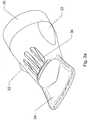
- Fig. 1ashows the hand and forearm of a patient placed within an elongate flexible plastics sleeve 10.
- the sleevecomprises an air inlet opening 12 at a distal end thereof for coupling to the output of a heated air supply (not shown).
- An appendage opening 14is provided at the opposing proximal end of the sleeve 10.
- the appendage opening 14is larger than the air inlet opening 12 and dimensioned so as to be capable of receiving hands and forearms of varying sizes and girths.
- the dimensions of the sleeve 10are as follows: length: 56.5cm; width: 21cm; width of air inlet opening: 6.5cm; and width of appendage opening: 20cm; and it is manufactured from a clear Linear low-density polyethylene (LLDPE) material having a thickness of 30 microns.
- LLDPELinear low-density polyethylene
- the thickness of the polyethylene materialmay be varied and will usually fall within the range of 12 microns to 100 microns.
- the sleeve 10is provided with a double-walled construction along the majority of its length.
- An inner sleeve layer 16extends within an outer sleeve layer 18 across its full width (see Fig. 2 ), and from the appendage opening 14 towards the air inlet opening 12.
- the inner sleeve layer 16terminates approximately 8cm from the air inlet opening 12.
- the inner and outer sleeve layers 16, 18are heat-sealed together - by means of heat fusion - along their longitudinal edges 20 (see Fig. 2 ).
- the most distal edges 19 of the inner sleeve 16 which extend laterally between the opposing longitudinal edges 20 proximate the air inlet opening 12are likewise heat-sealed together so as to form an isolated double-walled compartment for receipt of a patient's appendage.
- the most proximal edges of the inner sleeve layer 16 which extend laterally between the opposing longitudinal edges 20 at the appendage opening 14are contiguous with the outer sleeve layer 18 and the inner and outer sleeve layers 16, 18 are separated by a fold line at the appendage opening 14.
- the LLDPE materialmay conveniently be provided in the form of Lay Flat Tubing (LFT) which simplifies the process of manufacturing the sleeve 10.
- the air inlet opening 12is provided in the outer sleeve layer 18 and is dimensioned so as to be a friction fit over an end fitting (see Figs. 3a-e ).
- Air exit vents 22(see Fig. 2 ) - which may take the form of a incisions or slits through the polyethylene material - are provided proximate the proximal end of the outer sleeve layer 18.
- Opposing surfaces of the outer sleeve layer 18are heat-sealed together along lines 26 extending from either side of the air inlet opening 12 to the corresponding longitudinal edge 20.
- the lines 26are straight and form approximately 45 degree angles where they meet the longitudinal edges 20 and the distal lateral edge of the outer sleeve layer 18.
- the air inlet opening 12is attached to a nozzle 30 by forcing it past laterally extending lugs 32 serving to retain a friction fit connection between the two.
- An overhang portion of the outer sleeve layer 18 at the air inlet openingextends beyond the remainder of the outer sleeve layer 18 so as to provide a graspable tab 24 facilitating the manual coupling of the air inlet opening 12 the nozzle 30.
- the nozzle 30comprises a projecting surface 34 at its end most distal to the heated air supply (not shown).
- the nozzle 30 and its projecting surface 34bridge the spacing within the outer sleeve layer 18 lying between the most distal extent of the inner sleeve layer 16 and the air inlet opening 12 as shown in dashed lines in Figs 1a / 1b . Accordingly, when a patient places their hand and forearm within the isolated compartment defined by the inner sleeve layer 16, the projecting surface 34 provides a reference position onto which three fingers may be placed.
- heated airis forced through the openings 36 and is distributed circumferentially around the nozzle above and below its projecting surface 34.
- the temperature of the heated airis approximately 59 degrees and a temperature sensor with a safety cut-off is employed to prevent overheating.
- the openings 36direct the heated air both upwardly and downwardly with respect to the projecting surface 34 so as to facilitate an even distribution of warm air annularly around a patient's appendage.
- the presence of a baffle member 38ensures that heated air cannot be projected directly onto a patient's fingertips.
- the heated airis forced into the sleeve 10 by means of a fan and so it fills the two annular segments above and below the inner sleeve layer 16.
- the heated airvents from the two annular segments via their respective air exit openings 22.
- the air exit openingsare conveniently located on the outer sleeve layer 18 (see Fig. 2 ) so as to direct vented air away from the patient's body.
- the temperature and pressure differential existing between the compartment defined by the inner sleeve layer 16 and the respective annular segmentscauses the inner sleeve layer 16 to collapse against the skin of the patient. In doing so, this facilitates efficient heat transfer through the inner sleeve layer 16 onto around the entire exposed skin surface of the patient. Importantly, this occurs without the patient's skin coming into direct contact with any heated air.
- this apparatus of the present inventionprovides a means of achieving vasodilation in a consistent and controlled manner which is both convenient for the clinician and comfortable for the patient.
- distal and proximalare to be understood as describing positions with respect to a patient's body.
Landscapes
- Health & Medical Sciences (AREA)
- Vascular Medicine (AREA)
- Thermal Sciences (AREA)
- Engineering & Computer Science (AREA)
- Biomedical Technology (AREA)
- Heart & Thoracic Surgery (AREA)
- Physics & Mathematics (AREA)
- Life Sciences & Earth Sciences (AREA)
- Animal Behavior & Ethology (AREA)
- General Health & Medical Sciences (AREA)
- Public Health (AREA)
- Veterinary Medicine (AREA)
- Thermotherapy And Cooling Therapy Devices (AREA)
- Infusion, Injection, And Reservoir Apparatuses (AREA)
Description
- The present invention relates to a vasodilation assembly and particularly, though not exclusively, to apparatus for facilitating intravenous access to a peripheral vein via cannulation by circulating heated air around a limb in a controlled manner.
- Intravenous cannulation is a commonly performed invasive medical procedure involving the insertion of a cannula into a vein. Venous access facilitates blood sampling and the administration of fluids, medicines, nutritional supplements, contrast agents for imaging, chemotherapy drugs etc. In some patients difficulties can occur when attempting to locate a suitably prominent vein for venous access. In particular, patients who are young, elderly, obese, of black or Asian ethnicity, or who are intravenous drug users or undergoing regular cannulation - such as during chemotherapy or dialysis courses - may have less prominent peripheral veins. At best, cannulation difficulties can cause embarrassment or inconvenience to the clinician. At worst, it can cause genuine distress to the patient or delay urgent treatment.
- Various attempts have been made to overcome the problem of locating a suitable site for venous access. The most common solutions involve gently rubbing or tapping a proposed insertion site, lowering the relevant limb to promote venous engorgement, or applying proximal tourniquets. However, these basic approaches often fail to sufficiently increase vein prominence.
- It has also been proposed to apply warm moist towels around the intended cannulation site or to immerse the relevant limb in warm water. More advanced proposals have involved the wearing of electrically heated mitts or gloves by the patient prior to cannulation. Finally, it is also known to apply glyceryl trinitrate (GTN) ointment to the skin prior to attempted cannulation. However, these approaches each have shortcomings or disadvantages. For example, the application of warm moist towels or immersion of a limb in warm water each require a supply of water within a particular temperature range and a plentiful supply of replacement towels for each patient for infection control purposes. Moist towels and water tend to cool rapidly with time and so a consistent and continuous heating effect is not achieved. Commercially available mitts or gloves can be expensive and require strict infection control measures. GTN ointment cannot be applied to a whole limb and so repeated application may be required before a suitable site for venous access is located.
US 2 706 988 A discloses a human body heat treating apparatus in which heated air is applied directly to the surface of the skin inside a pliable casing of flexible supple material.- Given that intravenous cannulation is such a common medical procedure, even a modest reduction in the time taken to insert a cannula is important. Accordingly, a requirement exists for apparatus which overcomes or alleviates the shortcomings of prior approaches by providing a consistent, comfortable, safe and convenient means of facilitating intravenous access employing apparatus which is economic to produce as a single use item.
- According to a first aspect of the present invention, there is provided a flexible plastics sleeve of a double-walled construction comprising:
- (i) a transparent inner sleeve layer;
- (ii) a transparent outer sleeve layer;
- (iii) an annular space provided between the inner and outer sleeve layers;
- (iv) an air inlet opening formed in the outer sleeve layer at a distal end of the flexible plastics sleeve for coupling the annular space to a heated air supply;
- (v) an appendage opening at a proximal end of the flexible plastics sleeve opposite the distal end for accepting an appendage of a patient within a compartment defined by the inner sleeve layer;
- (vi) an air exit opening formed in the outer sleeve layer proximate the proximal end of the flexible plastics sleeve;
- Optionally, the flexible plastics sleeve is rectangular in shape and sealed along longitudinal edges thereof so as to fasten the inner and outer sleeve layers together and define two annular segments between the inner and outer sleeve layers. Two exit openings may be formed in the outer sleeve layer proximate the proximal end of the flexible plastics sleeve.
- Optionally, the inner and outer sleeve layers are formed from a single piece of linear low-density polyethylene (LLDPE) Lay Flat Tubing (LFT).
- Optionally, the inner and outer sleeve layers are contiguous and separated by a fold line proximate the appendage opening of the flexible plastics sleeve.
- Optionally, distal edges of the inner sleeve layer lying furthest from the appendage opening are sealed together to provide an enclosed inner compartment.
- Optionally, the air inlet opening is smaller than the appendage opening formed at the opposite proximal end.
- Optionally, a linear or non-linear tapered region is formed proximate the air inlet opening by sealing together opposite surfaces of the outer sleeve layer along two lines between each of its longitudinal edges and its lateral edge.
- Optionally, a portion of the outer sleeve layer at the air inlet opening extends beyond the remainder of the outer sleeve layer so as to provide a graspable tab facilitating the coupling of the air inlet opening to a heated air supply
- According to a second aspect of the present invention, there is provided a vasodilation assembly for facilitating intravenous cannulation, the assembly comprising:
- (i) a flexible plastics sleeve according to the first aspect;
- (ii) a heated air supply; and
- (iii) a conduit for conveying heated air from the air supply into the flexible plastics sleeve.
- By using transparent flexible plastics layers the weight of the sleeve is kept to a minimum whilst allowing both the patient and clinician to view the skin surface of the appendage.
- In one embodiment, the air inlet opening is dimensioned so as to be a friction fit over the conduit or any associated end fitting such that no separate fastening means is required.
- Optionally, the inner and outer sleeve layers are joined at the proximal end of the flexible plastics sleeve.
- The opening at the proximal end of the flexible plastics sleeve therefore allows an appendage of a patient to be placed within the inner sleeve layer.
- Optionally, the inner and outer sleeve layers are contiguous and separated by a fold line at the proximal end of the flexible plastics sleeve.
- In one embodiment, the flexible plastics sleeve may be manufactured from folded and heat-sealed linear low-density polyethylene (LLDPE) Lay Flat Tubing (LFT). It will be appreciated that alternative materials may be employed such as high-density polyethylene (HDPE), very low-density polyethylene (VLDPE) and low-density polyethylene (LDPE). This list is not exhaustive.
- The positioning of the air exit opening in the outer sleeve layer ensures that heated air is vented away from the patient's body. In practice, for manufacturing simplicity it may be necessary to form openings by making a single incision through both the inner and outer sleeve layers. However, during use, air pressure differentials at each surface of the inner sleeve layer causes it to collapse against the patient's skin ensuring that substantially no heated air passes through the innermost opening. The openings formed in the inner and outer sleeve layers therefore operate in the manner of a valve whereby the innermost opening is maintained in a closed position whilst the outermost opening expands.
- The inner sleeve layer is closed at its distal end so as to isolate an appendage located therein from incident heated air conveyed through the air inlet into the outer sleeve layer.
- Optionally, the most distal extent of the inner sleeve layer is spaced from the air inlet opening at a distal end of the outer sleeve layer so as to maintain a minimum spacing between an appendage located therein and incident heated air conveyed through the air inlet.
- Incident air is at its hottest as it enters the air inlet opening and so by maintaining a minimum spacing between it and the most distal extent of the inner sleeve patient discomfort can be minimised or avoided.
- Optionally, the annular space defines an annular passage for the flow of heated air between the air inlet and air exit openings.
- Depending upon the specific construction of the flexible plastics sleeve layers there may be a single annular space or two or more annular segments. In one embodiment, where the inner and outer sleeve layers are heat sealed together along their longitudinal edges there is formed two separate annular segments.
- Optionally, a nozzle is provided on the conduit for controlling the distribution of heated air from the air supply as it is introduced into the flexible plastics sleeve.
- Optionally, the nozzle comprises a projecting surface positioned at its end most distal to the conduit.
- In one embodiment, the projecting surface bridges the spacing between the most distal extent of the inner sleeve layer and the air inlet opening. The projecting surface provides a consistent reference point for the placement and support of part of a patient's appendage. For example, a patient's fingers may be rested on the projecting surface.
- Optionally, one or more openings are formed in the nozzle at a proximal position relative to its projecting surface.
- In one embodiment, openings are distributed circumferentially around the nozzle above and below its projecting surface so as to facilitate an even distribution of warm air annularly around a patient's appendage.
- Optionally, a baffle member protrudes out of the surface of the nozzle between the projecting surface and its one or more openings.
- The presence of the baffle member deflects the flow of heated air emitted from the opening(s) situated above the nozzle's projecting surface so as to protect the extremities - e.g. fingers - of a patient's appendage.
- Embodiments of the present invention will now be described, by way of example only, with reference to the accompanying drawings, in which:
Fig. 1a is a schematic cross-sectional view of a flexible double-walled plastics sleeve forming part of a vasodilation assembly before heated air is introduced therein;Fig. 1b is a schematic cross-sectional view of the flexible double-walled plastics sleeve as heated air passes through it;Fig. 2 is a schematic plan view of the flexible plastics sleeve ofFigs. 1a , b; andFigs. 3a-e are perspective side, end, top and bottom views of a nozzle for controlling the distribution of heated air as it is introduced into the flexible plastics sleeve.Fig. 1a shows the hand and forearm of a patient placed within an elongateflexible plastics sleeve 10. The sleeve comprises an air inlet opening 12 at a distal end thereof for coupling to the output of a heated air supply (not shown). An appendage opening 14 is provided at the opposing proximal end of thesleeve 10. Theappendage opening 14 is larger than theair inlet opening 12 and dimensioned so as to be capable of receiving hands and forearms of varying sizes and girths. In one example, the dimensions of thesleeve 10 are as follows: length: 56.5cm; width: 21cm; width of air inlet opening: 6.5cm; and width of appendage opening: 20cm; and it is manufactured from a clear Linear low-density polyethylene (LLDPE) material having a thickness of 30 microns. It will be appreciated that these dimensions are in no way limiting on the scope of the invention and suitable alterations may be made to accommodate different appendages and appendage sizes. Furthermore, the thickness of the polyethylene material may be varied and will usually fall within the range of 12 microns to 100 microns.- The
sleeve 10 is provided with a double-walled construction along the majority of its length. Aninner sleeve layer 16 extends within anouter sleeve layer 18 across its full width (seeFig. 2 ), and from the appendage opening 14 towards theair inlet opening 12. Theinner sleeve layer 16 terminates approximately 8cm from theair inlet opening 12. The inner and outer sleeve layers 16, 18 are heat-sealed together - by means of heat fusion - along their longitudinal edges 20 (seeFig. 2 ). The mostdistal edges 19 of theinner sleeve 16 which extend laterally between the opposinglongitudinal edges 20 proximate theair inlet opening 12 are likewise heat-sealed together so as to form an isolated double-walled compartment for receipt of a patient's appendage. The most proximal edges of theinner sleeve layer 16 which extend laterally between the opposinglongitudinal edges 20 at the appendage opening 14 are contiguous with theouter sleeve layer 18 and the inner and outer sleeve layers 16, 18 are separated by a fold line at theappendage opening 14. In one example, the LLDPE material may conveniently be provided in the form of Lay Flat Tubing (LFT) which simplifies the process of manufacturing thesleeve 10. - The
air inlet opening 12 is provided in theouter sleeve layer 18 and is dimensioned so as to be a friction fit over an end fitting (seeFigs. 3a-e ). Air exit vents 22 (seeFig. 2 ) - which may take the form of a incisions or slits through the polyethylene material - are provided proximate the proximal end of theouter sleeve layer 18. Opposing surfaces of theouter sleeve layer 18 are heat-sealed together alonglines 26 extending from either side of the air inlet opening 12 to the correspondinglongitudinal edge 20. In a non-limiting example, thelines 26 are straight and form approximately 45 degree angles where they meet thelongitudinal edges 20 and the distal lateral edge of theouter sleeve layer 18. - In use, the
air inlet opening 12 is attached to anozzle 30 by forcing it past laterally extendinglugs 32 serving to retain a friction fit connection between the two. An overhang portion of theouter sleeve layer 18 at the air inlet opening extends beyond the remainder of theouter sleeve layer 18 so as to provide agraspable tab 24 facilitating the manual coupling of the air inlet opening 12 thenozzle 30. - The
nozzle 30 comprises a projectingsurface 34 at its end most distal to the heated air supply (not shown). Thenozzle 30 and its projectingsurface 34 bridge the spacing within theouter sleeve layer 18 lying between the most distal extent of theinner sleeve layer 16 and the air inlet opening 12 as shown in dashed lines inFigs 1a /1b . Accordingly, when a patient places their hand and forearm within the isolated compartment defined by theinner sleeve layer 16, the projectingsurface 34 provides a reference position onto which three fingers may be placed. - Once the heated air supply is activated, heated air is forced through the
openings 36 and is distributed circumferentially around the nozzle above and below its projectingsurface 34. In one example, the temperature of the heated air is approximately 59 degrees and a temperature sensor with a safety cut-off is employed to prevent overheating. Theopenings 36 direct the heated air both upwardly and downwardly with respect to the projectingsurface 34 so as to facilitate an even distribution of warm air annularly around a patient's appendage. The presence of abaffle member 38 ensures that heated air cannot be projected directly onto a patient's fingertips. The heated air is forced into thesleeve 10 by means of a fan and so it fills the two annular segments above and below theinner sleeve layer 16. The heated air vents from the two annular segments via their respectiveair exit openings 22. The air exit openings are conveniently located on the outer sleeve layer 18 (seeFig. 2 ) so as to direct vented air away from the patient's body. - As illustrated in
Fig. 1b the temperature and pressure differential existing between the compartment defined by theinner sleeve layer 16 and the respective annular segments causes theinner sleeve layer 16 to collapse against the skin of the patient. In doing so, this facilitates efficient heat transfer through theinner sleeve layer 16 onto around the entire exposed skin surface of the patient. Importantly, this occurs without the patient's skin coming into direct contact with any heated air. - It will be appreciated that this apparatus of the present invention provides a means of achieving vasodilation in a consistent and controlled manner which is both convenient for the clinician and comfortable for the patient.
- Modifications and improvements may be made to the foregoing without departing from the scope of the invention as defined by the accompanying claims. For example, whilst two sleeve layers are described and illustrated, more than two layers could be employed. Whilst the sleeve has been described and illustrated as receiving a hand and arm of a patient, suitable adaptations could of course be made to accommodate other body parts such as the foot and leg.
- Unless the context allows otherwise, the terms distal and proximal are to be understood as describing positions with respect to a patient's body.
wherein the inner sleeve layer is closed at its distal end so as to isolate an appendage located therein from incident heated air conveyed through the air inlet opening into the outer sleeve layer.
Claims (12)
- A vasodilation assembly for facilitating intravenous cannulation, the assembly comprising:(i) a flexible plastics sleeve (10) according to any of claims 8 to 12;(ii) a heated air supply; and(iii) a conduit for conveying heated air from the air supply into the flexible plastics sleeve.
- A vasodilation assembly according to claim 1, wherein the inner and outer sleeve layers (16, 18) are joined at the proximal end of the flexible plastics sleeve (10).
- A vasodilation assembly according to claim 1, wherein the inner and outer sleeve layers (16, 18) are contiguous and separated by a fold line at the proximal end of the flexible plastics sleeve (10).
- A vasodilation assembly according to any preceding claim, wherein the most distal extent of the inner sleeve layer (16) is spaced from the air inlet opening (12) at a distal end of the outer sleeve layer (18) so as to maintain a minimum spacing between an appendage located therein and incident heated air conveyed through the air inlet opening (12).
- A vasodilation assembly according to any preceding claim, wherein a nozzle (30) is provided on the conduit for controlling the distribution of heated air from the air supply as it is introduced into the flexible plastics sleeve (10).
- A vasodilation assembly according to claim 5, wherein the nozzle (30) comprises a projecting surface (34) positioned at its end most distal to the conduit, and wherein one or more openings (36) are formed in the nozzle (30) at a proximal position relative to its projecting surface (34).
- A vasodilation assembly according to claim 5, wherein a baffle member (38) protrudes out of a surface of the nozzle (30) between the projecting surface (34) and its one or more openings (36).
- A flexible plastics sleeve of a double-walled construction comprising:(i) a transparent inner sleeve layer (16);(ii) a transparent outer sleeve layer (18);(iii) an annular space provided between the inner and outer sleeve layers (16, 18);(iv) an air inlet opening (12) formed in the outer sleeve layer (18) at a distal end of the flexible plastics sleeve for coupling the annular space to a heated air supply;(v) an appendage opening (14) at a proximal end of the flexible plastics sleeve opposite the distal end for accepting an appendage of a patient within a compartment defined by the inner sleeve layer (12); and(vi) an air exit opening (22) formed in the outer sleeve layer (18) proximate the proximal end of the flexible plastics sleeve;wherein the annular space defines an annular passage for the flow of heated air between the air inlet and air exit openings (12, 22),
wherein the inner sleeve layer (16) is closed at its distal end so as to isolate an appendage located therein from incident heated air conveyed through the air inlet opening (12) into the outer sleeve layer (18). - A flexible plastics sleeve as claimed in claim 8, wherein the sleeve (10) is rectangular in shape and sealed along longitudinal edges (20) thereof so as to fasten the inner and outer sleeve layers (16, 18) together and define two annular segments between the inner and outer sleeve layers (16, 18), and wherein two exit openings are formed in the outer sleeve layer (18) proximate the proximal end of the flexible plastics sleeve.
- A flexible plastics sleeve as claimed in claim 8 or 9, wherein the inner and outer sleeve layers (16, 18) are formed from a single piece of linear low-density polyethylene (LLDPE) Lay Flat Tubing (LFT).
- A flexible plastics sleeve as claimed in claim 9, wherein a linear or non-linear tapered region is formed proximate the air inlet opening (12) by sealing together opposite surfaces of the outer sleeve layer (18) along two lines (26) between each of its longitudinal edges (20) and its lateral edge.
- A flexible plastics sleeve as claimed in any of claims 8 to 11, wherein a portion of the outer sleeve layer (18) at the air inlet opening (12) extends beyond the remainder of the outer sleeve layer (18) so as to provide a graspable tab (24) facilitating the coupling of the air inlet opening (12) to a heated air supply.
Applications Claiming Priority (2)
| Application Number | Priority Date | Filing Date | Title |
|---|---|---|---|
| GBGB1220450.9AGB201220450D0 (en) | 2012-11-14 | 2012-11-14 | Vasodilation assembly |
| PCT/GB2013/053003WO2014076479A1 (en) | 2012-11-14 | 2013-11-14 | Vasodilation assembly |
Publications (2)
| Publication Number | Publication Date |
|---|---|
| EP2919725A1 EP2919725A1 (en) | 2015-09-23 |
| EP2919725B1true EP2919725B1 (en) | 2019-04-03 |
Family
ID=47470558
Family Applications (1)
| Application Number | Title | Priority Date | Filing Date |
|---|---|---|---|
| EP13794959.0AActiveEP2919725B1 (en) | 2012-11-14 | 2013-11-14 | Vasodilation assembly |
Country Status (11)
| Country | Link |
|---|---|
| US (1) | US10575982B2 (en) |
| EP (1) | EP2919725B1 (en) |
| CN (1) | CN104797218B (en) |
| AU (1) | AU2013346585B2 (en) |
| CA (1) | CA2891045C (en) |
| DK (1) | DK2919725T3 (en) |
| ES (1) | ES2730681T3 (en) |
| GB (1) | GB201220450D0 (en) |
| PT (1) | PT2919725T (en) |
| TR (1) | TR201909784T4 (en) |
| WO (1) | WO2014076479A1 (en) |
Families Citing this family (3)
| Publication number | Priority date | Publication date | Assignee | Title |
|---|---|---|---|---|
| KR101512594B1 (en)* | 2014-06-30 | 2015-04-15 | 송성진 | Heat storage type foot fomentation device for promoting energy and blood circulation |
| US9750895B1 (en) | 2014-08-29 | 2017-09-05 | Ziad A. Alsaifi | Venipuncture |
| US20200078535A1 (en)* | 2017-05-02 | 2020-03-12 | Care Essentials Pty Ltd | A Blanket for Venipuncture |
Citations (1)
| Publication number | Priority date | Publication date | Assignee | Title |
|---|---|---|---|---|
| US2706988A (en)* | 1951-11-19 | 1955-04-26 | Jarolux A G | Human body heat treating apparatus |
Family Cites Families (19)
| Publication number | Priority date | Publication date | Assignee | Title |
|---|---|---|---|---|
| US4452247A (en)* | 1981-08-31 | 1984-06-05 | Dalton Hebert | Heat treatment method and apparatus for horses |
| SU1174028A1 (en) | 1983-04-15 | 1985-08-23 | Институт Хирургии Им.А.В.Вишневского | Method and apparatus for curing burns of the second and third degree (its versions) |
| US5044364A (en)* | 1989-06-19 | 1991-09-03 | Primed Products, Inc. | Method and apparatus for flowing conditioned air onto person |
| US5683438A (en) | 1995-03-10 | 1997-11-04 | Stanford University | Apparatus and method for core body warming of mammals experiencing hypothermia |
| US5938693A (en) | 1995-06-30 | 1999-08-17 | Philips Electronics North America Corporation | Moist heat in vapor form health and beauty therapeutic system |
| US20050143797A1 (en)* | 2003-07-18 | 2005-06-30 | Thermotek, Inc. | Compression sequenced thermal therapy system |
| US6565593B2 (en) | 2001-03-12 | 2003-05-20 | Lawrence G. Diana | Peripheral vein dilation device and method |
| US20040243026A1 (en) | 2001-07-25 | 2004-12-02 | Joerg Toepfer | Thermal applicator and application system |
| US6820622B1 (en)* | 2002-06-07 | 2004-11-23 | Leonides Y. Teves | Thermal surgical drape |
| GB0230344D0 (en) | 2002-12-31 | 2003-02-05 | Filtvedt Marius | Device for applying a pulsating pressure to a local region of the body and applications thereof |
| US20060026743A1 (en)* | 2004-08-06 | 2006-02-09 | Brian Farnworth | Gas distribution garment |
| US7550000B2 (en)* | 2005-05-27 | 2009-06-23 | Smiths Medical Asd, Inc. | Restrictor regulated air flow blanket, system utilizing such blanket and method therefor |
| US20070162096A1 (en) | 2006-01-11 | 2007-07-12 | Medisuit Ltd. | Temperature regulating suit |
| US20080221493A1 (en) | 2006-12-07 | 2008-09-11 | Life Recovery Systems Hd, Llc | Apparatus for altering the body temperature of a patient and administering decompression to the patients torso |
| WO2008070849A2 (en)* | 2006-12-07 | 2008-06-12 | Life Recovery Systems Hd, Llc | Apparatus for altering the body temperature of a patient |
| US20090177184A1 (en)* | 2008-01-09 | 2009-07-09 | Christensen Scott A | Method and apparatus for improving venous access |
| CN201304025Y (en) | 2008-11-14 | 2009-09-09 | 穆焱成 | Medical constant-temperature transfusion heat-preservation device |
| US8771329B2 (en) | 2010-01-08 | 2014-07-08 | Carefusion 2200, Inc. | Methods and apparatus for enhancing vascular access in an appendage to enhance therapeutic and interventional procedures |
| AU2011280986B2 (en) | 2010-07-23 | 2015-11-12 | Avacen, Inc. | Methods and apparatus for therapeutic application of thermal energy |
- 2012
- 2012-11-14GBGBGB1220450.9Apatent/GB201220450D0/ennot_activeCeased
- 2013
- 2013-11-14CACA2891045Apatent/CA2891045C/enactiveActive
- 2013-11-14ESES13794959Tpatent/ES2730681T3/enactiveActive
- 2013-11-14PTPT13794959Tpatent/PT2919725T/enunknown
- 2013-11-14WOPCT/GB2013/053003patent/WO2014076479A1/enactiveApplication Filing
- 2013-11-14AUAU2013346585Apatent/AU2013346585B2/enactiveActive
- 2013-11-14EPEP13794959.0Apatent/EP2919725B1/enactiveActive
- 2013-11-14CNCN201380059365.5Apatent/CN104797218B/enactiveActive
- 2013-11-14USUS14/442,454patent/US10575982B2/enactiveActive
- 2013-11-14DKDK13794959.0Tpatent/DK2919725T3/enactive
- 2013-11-14TRTR2019/09784Tpatent/TR201909784T4/enunknown
Patent Citations (1)
| Publication number | Priority date | Publication date | Assignee | Title |
|---|---|---|---|---|
| US2706988A (en)* | 1951-11-19 | 1955-04-26 | Jarolux A G | Human body heat treating apparatus |
Also Published As
| Publication number | Publication date |
|---|---|
| CA2891045A1 (en) | 2014-05-22 |
| AU2013346585A1 (en) | 2015-05-28 |
| EP2919725A1 (en) | 2015-09-23 |
| ES2730681T3 (en) | 2019-11-12 |
| CN104797218A (en) | 2015-07-22 |
| CA2891045C (en) | 2020-12-22 |
| GB201220450D0 (en) | 2012-12-26 |
| US20160058611A1 (en) | 2016-03-03 |
| PT2919725T (en) | 2019-06-06 |
| TR201909784T4 (en) | 2019-07-22 |
| CN104797218B (en) | 2017-03-29 |
| AU2013346585B2 (en) | 2017-11-30 |
| US10575982B2 (en) | 2020-03-03 |
| WO2014076479A1 (en) | 2014-05-22 |
| DK2919725T3 (en) | 2019-07-01 |
Similar Documents
| Publication | Publication Date | Title |
|---|---|---|
| US10357396B2 (en) | Patient warming device with patient access | |
| US10668252B2 (en) | Integrated vascular delivery system | |
| US20140276254A1 (en) | Patient warming and dvt prevention system | |
| US20160346161A1 (en) | Compressive patient warming device | |
| US20060247745A1 (en) | Garment for the prevention or treatment of hypothermia and methods of treatment | |
| JP2016511054A5 (en) | ||
| US8926565B2 (en) | Intravenous catheter securement device | |
| EP2919725B1 (en) | Vasodilation assembly | |
| US20140194802A1 (en) | Protective Bandage Device | |
| CN203694283U (en) | Portable infusion heating bag | |
| CN205598080U (en) | Medical cold -proof limbs cover | |
| CN201223590Y (en) | Brace type infusion warming bag | |
| CN217366753U (en) | Venous transfusion glove | |
| CN215077255U (en) | Warm quilt | |
| CN210747430U (en) | Special patient clothing for indwelling transfusion port patient | |
| CN219741930U (en) | A kind of special hospital gown for breast surgery | |
| CN209950444U (en) | An infusion heating glove | |
| CN208851775U (en) | A hand warmer for infusion | |
| CN214432049U (en) | Vest is placed to chemotherapy pump based on PICC pipe | |
| CN211934503U (en) | Pressing and applying device after infusion | |
| CN205460247U (en) | Fixing device for children transfusion | |
| CN104436378A (en) | Portable infusion heating bag | |
| WO2020032892A2 (en) | Disposable catheter fixing cap |
Legal Events
| Date | Code | Title | Description |
|---|---|---|---|
| PUAI | Public reference made under article 153(3) epc to a published international application that has entered the european phase | Free format text:ORIGINAL CODE: 0009012 | |
| 17P | Request for examination filed | Effective date:20150519 | |
| AK | Designated contracting states | Kind code of ref document:A1 Designated state(s):AL AT BE BG CH CY CZ DE DK EE ES FI FR GB GR HR HU IE IS IT LI LT LU LV MC MK MT NL NO PL PT RO RS SE SI SK SM TR | |
| AX | Request for extension of the european patent | Extension state:BA ME | |
| DAX | Request for extension of the european patent (deleted) | ||
| STAA | Information on the status of an ep patent application or granted ep patent | Free format text:STATUS: EXAMINATION IS IN PROGRESS | |
| 17Q | First examination report despatched | Effective date:20171207 | |
| RAP1 | Party data changed (applicant data changed or rights of an application transferred) | Owner name:GREEN CROSS MEDICO LIMITED | |
| GRAP | Despatch of communication of intention to grant a patent | Free format text:ORIGINAL CODE: EPIDOSNIGR1 | |
| STAA | Information on the status of an ep patent application or granted ep patent | Free format text:STATUS: GRANT OF PATENT IS INTENDED | |
| INTG | Intention to grant announced | Effective date:20180430 | |
| GRAS | Grant fee paid | Free format text:ORIGINAL CODE: EPIDOSNIGR3 | |
| GRAJ | Information related to disapproval of communication of intention to grant by the applicant or resumption of examination proceedings by the epo deleted | Free format text:ORIGINAL CODE: EPIDOSDIGR1 | |
| GRAL | Information related to payment of fee for publishing/printing deleted | Free format text:ORIGINAL CODE: EPIDOSDIGR3 | |
| STAA | Information on the status of an ep patent application or granted ep patent | Free format text:STATUS: EXAMINATION IS IN PROGRESS | |
| INTC | Intention to grant announced (deleted) | ||
| RAP1 | Party data changed (applicant data changed or rights of an application transferred) | Owner name:GREEN CROSS MEDICO LIMITED | |
| GRAP | Despatch of communication of intention to grant a patent | Free format text:ORIGINAL CODE: EPIDOSNIGR1 | |
| STAA | Information on the status of an ep patent application or granted ep patent | Free format text:STATUS: GRANT OF PATENT IS INTENDED | |
| INTG | Intention to grant announced | Effective date:20181010 | |
| GRAA | (expected) grant | Free format text:ORIGINAL CODE: 0009210 | |
| STAA | Information on the status of an ep patent application or granted ep patent | Free format text:STATUS: THE PATENT HAS BEEN GRANTED | |
| RAP1 | Party data changed (applicant data changed or rights of an application transferred) | Owner name:GREEN CROSS MEDICO LIMITED | |
| AK | Designated contracting states | Kind code of ref document:B1 Designated state(s):AL AT BE BG CH CY CZ DE DK EE ES FI FR GB GR HR HU IE IS IT LI LT LU LV MC MK MT NL NO PL PT RO RS SE SI SK SM TR | |
| REG | Reference to a national code | Ref country code:GB Ref legal event code:FG4D | |
| REG | Reference to a national code | Ref country code:CH Ref legal event code:EP Ref country code:AT Ref legal event code:REF Ref document number:1114828 Country of ref document:AT Kind code of ref document:T Effective date:20190415 | |
| REG | Reference to a national code | Ref country code:DE Ref legal event code:R096 Ref document number:602013053370 Country of ref document:DE | |
| REG | Reference to a national code | Ref country code:IE Ref legal event code:FG4D | |
| REG | Reference to a national code | Ref country code:PT Ref legal event code:SC4A Ref document number:2919725 Country of ref document:PT Date of ref document:20190606 Kind code of ref document:T Free format text:AVAILABILITY OF NATIONAL TRANSLATION Effective date:20190524 | |
| REG | Reference to a national code | Ref country code:CH Ref legal event code:NV Representative=s name:MURGITROYD AND COMPANY, CH | |
| REG | Reference to a national code | Ref country code:DK Ref legal event code:T3 Effective date:20190624 | |
| REG | Reference to a national code | Ref country code:NL Ref legal event code:FP | |
| REG | Reference to a national code | Ref country code:SE Ref legal event code:TRGR | |
| REG | Reference to a national code | Ref country code:LT Ref legal event code:MG4D | |
| REG | Reference to a national code | Ref country code:NO Ref legal event code:T2 Effective date:20190403 | |
| REG | Reference to a national code | Ref country code:AT Ref legal event code:MK05 Ref document number:1114828 Country of ref document:AT Kind code of ref document:T Effective date:20190403 | |
| PG25 | Lapsed in a contracting state [announced via postgrant information from national office to epo] | Ref country code:CZ Free format text:LAPSE BECAUSE OF FAILURE TO SUBMIT A TRANSLATION OF THE DESCRIPTION OR TO PAY THE FEE WITHIN THE PRESCRIBED TIME-LIMIT Effective date:20190403 Ref country code:AL Free format text:LAPSE BECAUSE OF FAILURE TO SUBMIT A TRANSLATION OF THE DESCRIPTION OR TO PAY THE FEE WITHIN THE PRESCRIBED TIME-LIMIT Effective date:20190403 Ref country code:LT Free format text:LAPSE BECAUSE OF FAILURE TO SUBMIT A TRANSLATION OF THE DESCRIPTION OR TO PAY THE FEE WITHIN THE PRESCRIBED TIME-LIMIT Effective date:20190403 Ref country code:HR Free format text:LAPSE BECAUSE OF FAILURE TO SUBMIT A TRANSLATION OF THE DESCRIPTION OR TO PAY THE FEE WITHIN THE PRESCRIBED TIME-LIMIT Effective date:20190403 | |
| REG | Reference to a national code | Ref country code:ES Ref legal event code:FG2A Ref document number:2730681 Country of ref document:ES Kind code of ref document:T3 Effective date:20191112 | |
| PG25 | Lapsed in a contracting state [announced via postgrant information from national office to epo] | Ref country code:RS Free format text:LAPSE BECAUSE OF FAILURE TO SUBMIT A TRANSLATION OF THE DESCRIPTION OR TO PAY THE FEE WITHIN THE PRESCRIBED TIME-LIMIT Effective date:20190403 Ref country code:PL Free format text:LAPSE BECAUSE OF FAILURE TO SUBMIT A TRANSLATION OF THE DESCRIPTION OR TO PAY THE FEE WITHIN THE PRESCRIBED TIME-LIMIT Effective date:20190403 Ref country code:GR Free format text:LAPSE BECAUSE OF FAILURE TO SUBMIT A TRANSLATION OF THE DESCRIPTION OR TO PAY THE FEE WITHIN THE PRESCRIBED TIME-LIMIT Effective date:20190704 Ref country code:LV Free format text:LAPSE BECAUSE OF FAILURE TO SUBMIT A TRANSLATION OF THE DESCRIPTION OR TO PAY THE FEE WITHIN THE PRESCRIBED TIME-LIMIT Effective date:20190403 Ref country code:BG Free format text:LAPSE BECAUSE OF FAILURE TO SUBMIT A TRANSLATION OF THE DESCRIPTION OR TO PAY THE FEE WITHIN THE PRESCRIBED TIME-LIMIT Effective date:20190703 | |
| PG25 | Lapsed in a contracting state [announced via postgrant information from national office to epo] | Ref country code:IS Free format text:LAPSE BECAUSE OF FAILURE TO SUBMIT A TRANSLATION OF THE DESCRIPTION OR TO PAY THE FEE WITHIN THE PRESCRIBED TIME-LIMIT Effective date:20190803 Ref country code:AT Free format text:LAPSE BECAUSE OF FAILURE TO SUBMIT A TRANSLATION OF THE DESCRIPTION OR TO PAY THE FEE WITHIN THE PRESCRIBED TIME-LIMIT Effective date:20190403 | |
| REG | Reference to a national code | Ref country code:DE Ref legal event code:R097 Ref document number:602013053370 Country of ref document:DE | |
| PG25 | Lapsed in a contracting state [announced via postgrant information from national office to epo] | Ref country code:SK Free format text:LAPSE BECAUSE OF FAILURE TO SUBMIT A TRANSLATION OF THE DESCRIPTION OR TO PAY THE FEE WITHIN THE PRESCRIBED TIME-LIMIT Effective date:20190403 Ref country code:RO Free format text:LAPSE BECAUSE OF FAILURE TO SUBMIT A TRANSLATION OF THE DESCRIPTION OR TO PAY THE FEE WITHIN THE PRESCRIBED TIME-LIMIT Effective date:20190403 Ref country code:EE Free format text:LAPSE BECAUSE OF FAILURE TO SUBMIT A TRANSLATION OF THE DESCRIPTION OR TO PAY THE FEE WITHIN THE PRESCRIBED TIME-LIMIT Effective date:20190403 | |
| PLBE | No opposition filed within time limit | Free format text:ORIGINAL CODE: 0009261 | |
| STAA | Information on the status of an ep patent application or granted ep patent | Free format text:STATUS: NO OPPOSITION FILED WITHIN TIME LIMIT | |
| PG25 | Lapsed in a contracting state [announced via postgrant information from national office to epo] | Ref country code:SM Free format text:LAPSE BECAUSE OF FAILURE TO SUBMIT A TRANSLATION OF THE DESCRIPTION OR TO PAY THE FEE WITHIN THE PRESCRIBED TIME-LIMIT Effective date:20190403 | |
| 26N | No opposition filed | Effective date:20200106 | |
| PG25 | Lapsed in a contracting state [announced via postgrant information from national office to epo] | Ref country code:SI Free format text:LAPSE BECAUSE OF FAILURE TO SUBMIT A TRANSLATION OF THE DESCRIPTION OR TO PAY THE FEE WITHIN THE PRESCRIBED TIME-LIMIT Effective date:20190403 | |
| PG25 | Lapsed in a contracting state [announced via postgrant information from national office to epo] | Ref country code:CY Free format text:LAPSE BECAUSE OF FAILURE TO SUBMIT A TRANSLATION OF THE DESCRIPTION OR TO PAY THE FEE WITHIN THE PRESCRIBED TIME-LIMIT Effective date:20190403 | |
| PG25 | Lapsed in a contracting state [announced via postgrant information from national office to epo] | Ref country code:MT Free format text:LAPSE BECAUSE OF FAILURE TO SUBMIT A TRANSLATION OF THE DESCRIPTION OR TO PAY THE FEE WITHIN THE PRESCRIBED TIME-LIMIT Effective date:20190403 Ref country code:HU Free format text:LAPSE BECAUSE OF FAILURE TO SUBMIT A TRANSLATION OF THE DESCRIPTION OR TO PAY THE FEE WITHIN THE PRESCRIBED TIME-LIMIT; INVALID AB INITIO Effective date:20131114 | |
| PG25 | Lapsed in a contracting state [announced via postgrant information from national office to epo] | Ref country code:MK Free format text:LAPSE BECAUSE OF FAILURE TO SUBMIT A TRANSLATION OF THE DESCRIPTION OR TO PAY THE FEE WITHIN THE PRESCRIBED TIME-LIMIT Effective date:20190403 | |
| P01 | Opt-out of the competence of the unified patent court (upc) registered | Effective date:20230509 | |
| PGFP | Annual fee paid to national office [announced via postgrant information from national office to epo] | Ref country code:LU Payment date:20240509 Year of fee payment:11 | |
| PGFP | Annual fee paid to national office [announced via postgrant information from national office to epo] | Ref country code:NL Payment date:20240510 Year of fee payment:11 | |
| PGFP | Annual fee paid to national office [announced via postgrant information from national office to epo] | Ref country code:DK Payment date:20240510 Year of fee payment:11 Ref country code:MC Payment date:20240510 Year of fee payment:11 | |
| PGFP | Annual fee paid to national office [announced via postgrant information from national office to epo] | Ref country code:CH Payment date:20240514 Year of fee payment:11 | |
| PGFP | Annual fee paid to national office [announced via postgrant information from national office to epo] | Ref country code:FI Payment date:20240510 Year of fee payment:11 | |
| PGFP | Annual fee paid to national office [announced via postgrant information from national office to epo] | Ref country code:PT Payment date:20240510 Year of fee payment:11 | |
| PGFP | Annual fee paid to national office [announced via postgrant information from national office to epo] | Ref country code:BE Payment date:20240510 Year of fee payment:11 | |
| REG | Reference to a national code | Ref country code:DE Ref legal event code:R081 Ref document number:602013053370 Country of ref document:DE Owner name:AIRGLOVE MEDICAL LIMITED, GB Free format text:FORMER OWNER: GREEN CROSS MEDICO LTD., HAMILTON, GB | |
| REG | Reference to a national code | Ref country code:GB Ref legal event code:732E Free format text:REGISTERED BETWEEN 20241031 AND 20241106 | |
| PGFP | Annual fee paid to national office [announced via postgrant information from national office to epo] | Ref country code:DE Payment date:20241129 Year of fee payment:12 | |
| PGFP | Annual fee paid to national office [announced via postgrant information from national office to epo] | Ref country code:NO Payment date:20241129 Year of fee payment:12 | |
| PGFP | Annual fee paid to national office [announced via postgrant information from national office to epo] | Ref country code:GB Payment date:20241129 Year of fee payment:12 | |
| PGFP | Annual fee paid to national office [announced via postgrant information from national office to epo] | Ref country code:FR Payment date:20241127 Year of fee payment:12 | |
| PGFP | Annual fee paid to national office [announced via postgrant information from national office to epo] | Ref country code:IE Payment date:20241127 Year of fee payment:12 | |
| PGFP | Annual fee paid to national office [announced via postgrant information from national office to epo] | Ref country code:IT Payment date:20241126 Year of fee payment:12 Ref country code:ES Payment date:20241204 Year of fee payment:12 | |
| PGFP | Annual fee paid to national office [announced via postgrant information from national office to epo] | Ref country code:SE Payment date:20241129 Year of fee payment:12 | |
| PGFP | Annual fee paid to national office [announced via postgrant information from national office to epo] | Ref country code:TR Payment date:20241112 Year of fee payment:12 | |
| REG | Reference to a national code | Ref country code:ES Ref legal event code:PC2A Owner name:AIRGLOVE MEDICAL LIMITED Effective date:20250220 | |
| REG | Reference to a national code | Ref country code:DK Ref legal event code:EBP Effective date:20241130 | |
| REG | Reference to a national code | Ref country code:CH Ref legal event code:PL | |
| PG25 | Lapsed in a contracting state [announced via postgrant information from national office to epo] | Ref country code:MC Free format text:LAPSE BECAUSE OF NON-PAYMENT OF DUE FEES Effective date:20241202 | |
| PG25 | Lapsed in a contracting state [announced via postgrant information from national office to epo] | Ref country code:FI Free format text:LAPSE BECAUSE OF NON-PAYMENT OF DUE FEES Effective date:20241114 | |
| REG | Reference to a national code | Ref country code:NL Ref legal event code:MM Effective date:20241201 | |
| PG25 | Lapsed in a contracting state [announced via postgrant information from national office to epo] | Ref country code:LU Free format text:LAPSE BECAUSE OF NON-PAYMENT OF DUE FEES Effective date:20241114 | |
| REG | Reference to a national code | Ref country code:CH Ref legal event code:PL | |
| PG25 | Lapsed in a contracting state [announced via postgrant information from national office to epo] | Ref country code:PT Free format text:LAPSE BECAUSE OF NON-PAYMENT OF DUE FEES Effective date:20250514 | |
| PG25 | Lapsed in a contracting state [announced via postgrant information from national office to epo] | Ref country code:CH Free format text:LAPSE BECAUSE OF NON-PAYMENT OF DUE FEES Effective date:20241130 | |
| PG25 | Lapsed in a contracting state [announced via postgrant information from national office to epo] | Ref country code:NL Free format text:LAPSE BECAUSE OF NON-PAYMENT OF DUE FEES Effective date:20241201 | |
| REG | Reference to a national code | Ref country code:BE Ref legal event code:MM Effective date:20241130 |