EP2916901B1 - Intermittent catheter assembly - Google Patents
Intermittent catheter assemblyDownload PDFInfo
- Publication number
- EP2916901B1 EP2916901B1EP13715036.3AEP13715036AEP2916901B1EP 2916901 B1EP2916901 B1EP 2916901B1EP 13715036 AEP13715036 AEP 13715036AEP 2916901 B1EP2916901 B1EP 2916901B1
- Authority
- EP
- European Patent Office
- Prior art keywords
- introducer element
- applicator
- catheter assembly
- sheath
- elongated introducer
- Prior art date
- Legal status (The legal status is an assumption and is not a legal conclusion. Google has not performed a legal analysis and makes no representation as to the accuracy of the status listed.)
- Active
Links
Images


Classifications
- A—HUMAN NECESSITIES
- A61—MEDICAL OR VETERINARY SCIENCE; HYGIENE
- A61M—DEVICES FOR INTRODUCING MEDIA INTO, OR ONTO, THE BODY; DEVICES FOR TRANSDUCING BODY MEDIA OR FOR TAKING MEDIA FROM THE BODY; DEVICES FOR PRODUCING OR ENDING SLEEP OR STUPOR
- A61M25/00—Catheters; Hollow probes
- A61M25/0043—Catheters; Hollow probes characterised by structural features
- A61M25/0045—Catheters; Hollow probes characterised by structural features multi-layered, e.g. coated
- A—HUMAN NECESSITIES
- A61—MEDICAL OR VETERINARY SCIENCE; HYGIENE
- A61M—DEVICES FOR INTRODUCING MEDIA INTO, OR ONTO, THE BODY; DEVICES FOR TRANSDUCING BODY MEDIA OR FOR TAKING MEDIA FROM THE BODY; DEVICES FOR PRODUCING OR ENDING SLEEP OR STUPOR
- A61M25/00—Catheters; Hollow probes
- A61M25/01—Introducing, guiding, advancing, emplacing or holding catheters
- A61M25/0105—Steering means as part of the catheter or advancing means; Markers for positioning
- A61M25/0111—Aseptic insertion devices
- A—HUMAN NECESSITIES
- A61—MEDICAL OR VETERINARY SCIENCE; HYGIENE
- A61M—DEVICES FOR INTRODUCING MEDIA INTO, OR ONTO, THE BODY; DEVICES FOR TRANSDUCING BODY MEDIA OR FOR TAKING MEDIA FROM THE BODY; DEVICES FOR PRODUCING OR ENDING SLEEP OR STUPOR
- A61M25/00—Catheters; Hollow probes
- A61M25/0043—Catheters; Hollow probes characterised by structural features
- A61M25/0054—Catheters; Hollow probes characterised by structural features with regions for increasing flexibility
- A—HUMAN NECESSITIES
- A61—MEDICAL OR VETERINARY SCIENCE; HYGIENE
- A61M—DEVICES FOR INTRODUCING MEDIA INTO, OR ONTO, THE BODY; DEVICES FOR TRANSDUCING BODY MEDIA OR FOR TAKING MEDIA FROM THE BODY; DEVICES FOR PRODUCING OR ENDING SLEEP OR STUPOR
- A61M25/00—Catheters; Hollow probes
- A61M25/01—Introducing, guiding, advancing, emplacing or holding catheters
- A61M25/0105—Steering means as part of the catheter or advancing means; Markers for positioning
- A61M25/0119—Eversible catheters
- A—HUMAN NECESSITIES
- A61—MEDICAL OR VETERINARY SCIENCE; HYGIENE
- A61M—DEVICES FOR INTRODUCING MEDIA INTO, OR ONTO, THE BODY; DEVICES FOR TRANSDUCING BODY MEDIA OR FOR TAKING MEDIA FROM THE BODY; DEVICES FOR PRODUCING OR ENDING SLEEP OR STUPOR
- A61M25/00—Catheters; Hollow probes
- A61M25/0043—Catheters; Hollow probes characterised by structural features
- A61M2025/006—Catheters; Hollow probes characterised by structural features having a special surface topography or special surface properties, e.g. roughened or knurled surface
- A—HUMAN NECESSITIES
- A61—MEDICAL OR VETERINARY SCIENCE; HYGIENE
- A61M—DEVICES FOR INTRODUCING MEDIA INTO, OR ONTO, THE BODY; DEVICES FOR TRANSDUCING BODY MEDIA OR FOR TAKING MEDIA FROM THE BODY; DEVICES FOR PRODUCING OR ENDING SLEEP OR STUPOR
- A61M25/00—Catheters; Hollow probes
- A61M2025/0098—Catheters; Hollow probes having a strain relief at the proximal end, e.g. sleeve
- A—HUMAN NECESSITIES
- A61—MEDICAL OR VETERINARY SCIENCE; HYGIENE
- A61M—DEVICES FOR INTRODUCING MEDIA INTO, OR ONTO, THE BODY; DEVICES FOR TRANSDUCING BODY MEDIA OR FOR TAKING MEDIA FROM THE BODY; DEVICES FOR PRODUCING OR ENDING SLEEP OR STUPOR
- A61M25/00—Catheters; Hollow probes
- A61M25/01—Introducing, guiding, advancing, emplacing or holding catheters
- A61M25/02—Holding devices, e.g. on the body
- A61M2025/0293—Catheter, guide wire or the like with means for holding, centering, anchoring or frictionally engaging the device within an artificial lumen, e.g. tube
- A—HUMAN NECESSITIES
- A61—MEDICAL OR VETERINARY SCIENCE; HYGIENE
- A61M—DEVICES FOR INTRODUCING MEDIA INTO, OR ONTO, THE BODY; DEVICES FOR TRANSDUCING BODY MEDIA OR FOR TAKING MEDIA FROM THE BODY; DEVICES FOR PRODUCING OR ENDING SLEEP OR STUPOR
- A61M25/00—Catheters; Hollow probes
- A61M25/01—Introducing, guiding, advancing, emplacing or holding catheters
- A61M25/06—Body-piercing guide needles or the like
- A61M25/0662—Guide tubes
- A61M2025/0681—Systems with catheter and outer tubing, e.g. sheath, sleeve or guide tube
- A—HUMAN NECESSITIES
- A61—MEDICAL OR VETERINARY SCIENCE; HYGIENE
- A61M—DEVICES FOR INTRODUCING MEDIA INTO, OR ONTO, THE BODY; DEVICES FOR TRANSDUCING BODY MEDIA OR FOR TAKING MEDIA FROM THE BODY; DEVICES FOR PRODUCING OR ENDING SLEEP OR STUPOR
- A61M2202/00—Special media to be introduced, removed or treated
- A61M2202/04—Liquids
- A61M2202/0496—Urine
- A—HUMAN NECESSITIES
- A61—MEDICAL OR VETERINARY SCIENCE; HYGIENE
- A61M—DEVICES FOR INTRODUCING MEDIA INTO, OR ONTO, THE BODY; DEVICES FOR TRANSDUCING BODY MEDIA OR FOR TAKING MEDIA FROM THE BODY; DEVICES FOR PRODUCING OR ENDING SLEEP OR STUPOR
- A61M2210/00—Anatomical parts of the body
- A61M2210/10—Trunk
- A61M2210/1078—Urinary tract
- A61M2210/1089—Urethra
- A61M2210/1096—Male
- A—HUMAN NECESSITIES
- A61—MEDICAL OR VETERINARY SCIENCE; HYGIENE
- A61M—DEVICES FOR INTRODUCING MEDIA INTO, OR ONTO, THE BODY; DEVICES FOR TRANSDUCING BODY MEDIA OR FOR TAKING MEDIA FROM THE BODY; DEVICES FOR PRODUCING OR ENDING SLEEP OR STUPOR
- A61M25/00—Catheters; Hollow probes
- A61M25/0017—Catheters; Hollow probes specially adapted for long-term hygiene care, e.g. urethral or indwelling catheters to prevent infections
- A—HUMAN NECESSITIES
- A61—MEDICAL OR VETERINARY SCIENCE; HYGIENE
- A61M—DEVICES FOR INTRODUCING MEDIA INTO, OR ONTO, THE BODY; DEVICES FOR TRANSDUCING BODY MEDIA OR FOR TAKING MEDIA FROM THE BODY; DEVICES FOR PRODUCING OR ENDING SLEEP OR STUPOR
- A61M25/00—Catheters; Hollow probes
- A61M25/01—Introducing, guiding, advancing, emplacing or holding catheters
- A61M25/0102—Insertion or introduction using an inner stiffening member, e.g. stylet or push-rod
Definitions
- the present disclosureis generally directed to an intermittent catheter assembly adapted for a user to insert the catheter through the urethra to drain urine from the bladder and, more particularly, to an intermittent catheter assembly with a reusable insertion component for use with a single-use, component which may be disposable, for example, by flushing it down a toilet.
- Intermittent catheter assembliesare a good option for many users who suffer from various abnormalities of the urinary system.
- a common situationis where single-use, packaged, ready-to-use sterile catheters are utilized.
- An important criterion for single-use, ready-to-use productsis that they be entirely user-friendly under a wide variety of different conditions.
- US 2006/0173422describes an introducer apparatus having a sleeve fixation mechanism that fixes a part of a sleeve outside an elongated member, i.e. medical device, so that when the elongated member is moved in a distal direction, a distal part of the elongated member engages the sleeve and unfurls it between the outside surface of the elongated member and the inside of a bodily passage.
- US 5,792,114describes an introducer for sterile insertion of catheter into urethra - having a convolutionally rearward transported shroud interposed over and between the introducer's distal portion and the body internal organ surfaces, for sterile catheter passage through the introducer and into the organ.
- an intermittent catheter assemblyincludes an elongated introducer element that has a proximal insertion end and a distal end remote from the proximal insertion end.
- the elongated introducer elementis formed of a flexible material adapted for insertion into a urethra during a catheterization procedure and has at least one slit extending longitudinally along at least a portion thereof.
- the assemblyalso includes a sheath having a first end and a second end being inverted relative to the first end of the sheath to define inner and outer sleeve portions and a space therebetween.
- the inner sleeve portiondefines a flow path for urine.
- the elongated introducer elementis disposed in the space defined between the inner and outer sleeve portions.
- the inner sleeve portionis extendable through the at least one slit of the elongated introducer element so as to be disposed within the elongated introducer element and cover an inner surface of the elongated introducer element.
- the inner sleeve portionseparates the inner surface of the elongated introducer element from the urine flow path. Additionally, the outer sleeve portion extends over an outer surface of the elongated introducer element to separate the outer surface of the elongated introducer element from the urethra.
- an intermittent catheter assemblyin another example, includes an elongated introducer element that has a proximal insertion end and a distal end remote from the proximal insertion end.
- the elongated introducer elementis formed of a flexible material adapted for insertion into a urethra during a catheterization procedure. Additionally, the elongated introducer element has at least one slit extending longitudinally along at least a portion thereof.
- the assemblyalso includes an applicator that has an opening for receiving the elongated introducer element and a sheath that has a first end secured to the applicator about the opening. The sheath also has a second end that defines a discharge opening.
- the second end of the sheathis inverted relative to the first end of the sheath and extends into the opening of the applicator to define inner and outer sleeve portions. Additionally, the inner sleeve portion defines a flow path for urine through the discharge opening.
- the assemblyfurther includes a holding element that is associated with the second end of the sheath for extending the inner sleeve portion through the at least one slit of the elongated introducer element so as to dispose the inner sleeve portion within the elongated introducer element.
- the inner sleeve portioncovers an inner surface of the elongated introducer element to separate the inner surface of the elongated introducer element from the urine flow path.
- the outer sleeve portionextends over an outer surface of the elongated introducer element to separate the outer surface from the urethra.
- an intermittent catheter assemblyin another example, includes an elongated introducer element that has a proximal insertion end and a distal end remote from the proximal insertion end.
- the elongated introducer elementis formed of a flexible material adapted for insertion into a urethra during a catheterization procedure.
- the elongated introducer elementhas at least one slit extending longitudinally along at least a portion thereof.
- the assemblyalso includes an applicator that has at least one opening for receiving the elongated introducer element and a drainage lumen for the drainage of urine.
- the assemblyalso includes a sheath having a first end and a second end being inverted relative to the first end of the sheath to define inner and outer sleeve portions and a space therebetween.
- the inner sleeve portiondefines a urine flow path.
- the first end of the sheathis secured to the applicator about the at least one opening of the applicator.
- the opening of the applicatoris in communication with the space defined between the inner and outer sleeve portions.
- the second end of the sheathis secured to the applicator about the drainage lumen wherein the urine flow path defined by the inner sleeve portion is in fluid communication with the drainage lumen of the applicator.
- the elongated introducer elementis insertable through the opening of the applicator and into the space defined between the inner and outer sleeve portions.
- the outer sleeve portionextends over an outer surface of the elongated introducer element and the inner sleeve portion extends through the slit and covers an inner surface of the elongated introducer element to separate the inner surface of the elongated introducer element from the urine flow path.
- an intermittent catheter assemblycomprising an elongated introducer element formed of a flexible material adapted for insertion into a urethra during a catheterization procedure.
- the introducer elementhas at least one slit extending longitudinally along at least a substantial portion of its length.
- the catheter assemblyalso includes an applicator having an opening, and a thin sheath having a first end is secured to the applicator about the opening.
- the thin sheathalso has a second end defining a discharge opening which is inverted relative to the first end of the sheath and extends into the opening in the applicator to define inner and outer sleeve portions.
- the inner sleeve portiondefines a flow path for urine through the discharge opening.
- the catheter assemblyalso includes a holding element associated with the second end of the sheath for extending the inner sleeve portion through the slit(s) to be disposed within the introducer element. This serves to separate an inner surface of the introducer element from the urine flow path so the introducer element is never exposed to urine during a catheterization procedure.
- the applicatorreceives the introducer element through the opening and extends the outer sleeve portion over an outer surface of the elongated introducer element to separate it from the urethra. Accordingly, the portion of the introducer element which is located within the urethra during a catheterization procedure is entirely covered by the inner and outer sleeve portions of the sheath and is therefore suitable for reuse.
- the introducer elementcomprises a tube having a single slit which extends along the entire length thereof from a proximal insertion end to a distal end remote therefrom.
- the proximal insertion end of the introducer elementis advantageously beveled to be at other than a right angle to an axis of the introducer element to aid insertion into a urethra during a catheterization procedure.
- the proximal insertion end of the introducer elementit has been found desirable for the proximal insertion end of the introducer element to beveled so as to be at an angle of between about 15° and about 30° to an axis of the introducer element.
- the slitextending longitudinally along at least a substantial portion of the length of the elongated introducer element, it may advantageously have a width of between about 1.0 mm and 1.5 mm.
- the applicatormay suitably comprise a collar generally surrounding the first end of the thin sheath and also defining a stop during insertion of the elongated introducer element into a urethra.
- the holding elementit may advantageously comprise a cord having a first end which is attached to the second end of the thin sheath, and the cord may also have a second end with a finger grip tab attached thereto.
- the second end of the thin sheathis secured to generally diametrically opposed portions of the applicator to define the holding element which is associated with the first end of the sheath.
- the introducer elementhas a pair of opposed slits extending longitudinally along a substantial portion of the introducer element from a proximal insertion end toward a distal end thereof.
- the reference numeral 20designates generally an intermittent catheter assembly comprising an elongated introducer element 22 which may be formed of a flexible material and is adapted for insertion into a urethra during a catheterization procedure.
- the introducer element 22has at least one slit 24 extending longitudinally along a portion of its length and preferably at least a substantial portion of its length.
- the catheter assembly 20also includes an applicator generally designated 26 which has an opening 28, and a thin sheath, sleeve or shroud 30 having a first end 30a is secured to the applicator 26 about the opening 28.
- the thin sheath 30also has a second end 30b defining a discharge opening 32 which is inverted relative to the first end 30a of the sheath 30 and extends into the opening 28 in the applicator 26 to define inner 34a and outer 34b sleeve portions.
- the inner sleeve portion 34adefines a flow path 33 (as illustrated in Fig. 3A ) for urine through the discharge opening 32.
- the catheter assembly 20also includes a holding element 36 associated with the second end 30b of the sheath 30 for extending the inner sleeve portion 34a through the slit(s) such as 24 to be disposed within the introducer element 22.
- the applicator 26receives the introducer element 22 through the opening 28 and extends the outer sleeve portion 34b over an outer surface 22b of the elongated introducer element 22 to separate it from the urethra.
- sleeve 30everts over the proximal insertion end 38 of introducer element 22 so that the outer sleeve portion 34b extends over outer surface 22b and inner sleeve portion 34a extends over inner surface 22a of introducer element 22.
- the portion of the introducer element 22 which is located within the urethra during a catheterization procedureis entirely covered by the inner 34a and outer 34b sleeve portions of the sheath 30 and is therefore suitable for reuse, as shown in Fig. 3A .
- the introducer element 22comprises a tube having a single slit 24 which extends along the entire length thereof from a proximal insertion end 38a to a distal end 38b remote therefrom.
- the proximal insertion end 38a of the introducer element 22may be beveled to be at other than a right angle to the longitudinal axis 40 of the introducer element 22 to aid insertion into a urethra during a catheterization procedure.
- the slit 24extending along the longitudinal axis 40 for the entire length of the elongated introducer element 22, it may have a width of between about 1.0 mm and 1.5 mm.
- the applicator 28may include a collar 42 surrounding the first end 30a of the sheath 30 and the applicator defines a stop during insertion of the introducer element 22 into a urethra.
- the holding element 36may comprise a cord having a first end 36a which is attached to the second end 30b of the thin sheath 30, and the cord 36 may also have a second end 36b with a finger grip tab 44 attached thereto.
- the introducer element 22may be formed of a flexible material and is preferable formed of a flexible, shape-memory material, such as a flexible shape-memory polymer.
- Introducer element 22 and the other introducer elements disclosed hereinmay be formed, for example, from polyamides, polyvinylchloride, polypropylene, polyester, polyurethane, polyesterurethane, polyetherurethane, poly(ester-etherurethane), fluoropolymers such as, but not limited to, polyvinylidene difluoride, polyvinylidene fluoride, expanded polytetrafluoroethylene, fluorinated ethylene propylene, perfluroalkoxy and combinations of any of the above listed materials.
- the introducer elementis constructed from a material that allows the introducer element to be bent into a stowed or compact configuration so that it may be, for instance, coiled and carried in a pocket, if desired, and then changed into a generally straight or slightly curved configuration for use during catheterization.
- Introducer element 22also may be reusable and need not be sterile since the portion inserted into the urethra is entirely covered by the sheath 30 during a catheterization procedure.
- the applicator 26, thin sheath 30, and holding element 36may be made of biodegradable materials and, preferably, flushable biodegradable materials.
- Applicator 26, thin sheath 30, and holding element 36may be provided in a package 46, which also may be made of biodegradable materials, in a sterile condition for immediate use when removed (see Figs. 7, 7A and 8 ).
- the other applicators, thin sheaths and packaging described hereinalso may be made of such biodegradable materials.
- introducer element 22 and the other introducer elements described hereinalso may be made from such biodegradable materials, preferably flexible biodegradable materials and, more preferably, flexible shape-memory, biodegradable materials.
- biodegradable materials for forming the applicator 26, the thin sheath 30, the holding element 36, introducer element 22 and package 46may comprise any of a wide range of materials that are flushable for ease of disposal after use.
- Potential biodegradable polymersinclude, but are not limited to: polyalkenedicarboylates, poly(alkylcyanoacrylate), polyamides, polyamide-enamines, polyanhydrides, poly( ⁇ -caprolactone), polyesters, polyesterurethane, polyetherurethane, poly(ester-etherurethane), polyglycolide, polyhydroxyalkanoates, polyhydroxybutyrate, poly(hydroxybutyrate-co-valerate), polylactide, poly(p-dioxanone), poly(trimethylene carbonate), polyureas, polyurethane, cellulose, chitin, chitosan, collagen, corn, lignin, soy protein, starch, succinic acid and sugar cane.
- the flushable materialcould be any of
- each of the packages 46includes a single, sterile ready-to-use catheter element 50 which is comprised of an applicator 26, thin sheath 30, and holding element 36. As shown in Fig.
- the kit 48may comprise a semi-rigid carrying case 52 formed of a paperboard material to have an openable top 52a, a holder 52b for the elongated introducer element 22, and a pocket 52c for, by way of example, a dozen ready-to-use catheter elements 50 with four of each disposed in three adjacent rows within the pocket 52c.
- the second end 30b' of the thin sheath 30'may be secured to generally diametrically opposed portions 46a and 46b of the applicator 26' to define the holding element which may be associated with the second end 30b' of the sheath 30'.
- the introducer element 22'includes a pair of opposed members or arms 24a' and 24b' each extending parallel to the longitudinal axis 40' of the introducer element 22' from a proximal insertion end 38a' toward a distal end 38b' thereof. Arms 24a' and 24b' define a slit or gap 23', and preferably a planar slit or gap, therebetween.
- the applicator 26'has an opening 28', and the first end 30a' of the thin sheath 30' may be secured to the applicator 26' about the opening 28'.
- the second end 30b' of the thin sheath 30'defines a discharge opening 32' which may be inverted relative to the first end 30a' of the sheath 30' and extends into the opening 28' in the applicator 26' to define inner 34a' and outer 34b' sleeve portions.
- the inner sleeve portion 34a'defines a flow path 33' (shown in Fig. 10A ) for urine through the discharge opening 32'.
- the catheter assembly 20 'also may include a holding element 36' (see Fig.
- the applicator 26'receives the introducer element 22' through the opening 28' and extends the outer sleeve portion 34b' over an outer surface 22b' of the elongated introducer element 22' to separate it from the urethra.
- sleeve 30'everts over the proximal insertion end 38' of introducer element 22' so that the outer sleeve portion 34b' extends over outer surface 22b' and inner sleeve portion 34a' extends over inner surface 22a' of introducer element 22'. Accordingly, the portion of the introducer element 22' which is located within the urethra during a catheterization procedure is entirely covered by the inner 34a' and outer 34b' sleeve portions of the sheath 30' and is therefore suitable for reuse.
- the introducer element 22'comprises a pair of opposed elements or arms 24a' and 24b' which extend longitudinally and define a slit 23' that extends along at least a portion of the introducer element 22' and preferably from the proximal insertion end 38a' toward the distal end 38b' of introducer element 22'.
- the portion of the arms 24a' and 24b' near the proximal insertion end 38a' of the introducer element 22'may be rounded, as will be appreciated by referring to Fig. 11 , which will facilitate insertion into a urethra during a catheterization procedure.
- the elongated introducer element 22'may include a pair of gripping elements 54a and 54b associated with the distal end 38b' remote from the proximal insertion end 38a' beyond slit 23' (see Figs. 9-11 ).
- the introducer element 22' in the embodiment illustrated in Figs, 9-11may be formed of a flexible, shape-retaining material such as any of the materials described above with respect to introducer element 22 so it can be coiled and carried in a pocket, if desired.
- the introducer element 22'is reusable and need not be sterile since the portion inserted into the urethra is entirely covered by the sheath 30' during a catheterization procedure.
- the applicator 26', the thin sheath 30', and the holding element 36'may be made of flushable biodegradable materials and provided in a package 46' in a sterile condition for immediate use when removed (see Figs. 13 and 14 ).
- each of the packages 46'includes a single, sterile ready-to-use catheter element 50' which is comprised of an applicator 26', thin sheath 30', and holding element 36'. As shown in Fig.
- the kit 48'may comprise a semi-rigid carrying case 52' formed of paperboard material with an openable top 52a', a holder (not shown) for the introducer element (not shown), and a pocket 52c' for, e.g., fifteen packages 46' of ready-to-use catheter elements (not shown), i.e., three each in five adjacent rows in the pocket 52c'.
- one of the catheter elements 50is first removed from one of the packages 46 after it has been opened ( Fig. 7A ), following which the grip tab 44 is used to extend the inner sleeve portion 34a of the sheath 30 while gripping the collar 42.
- the slit 24is used to locate the inner sleeve portion 34a within the introducer element 22 (see Figs. 1 and 2 ).
- the collar 42is used to extend the outer sleeve portion 34b over a substantial portion of the outer surface 22b of the introducer element 22 to be inserted into the urethra (see Figs. 3 and 4 ).
- the collar 42 and the grip tab 44can again be used to remove the sheath 30 from the introducer element 22 (see Fig. 5 ), and the catheter element 50 comprised of the applicator 26, the sheath 30 and the grip tab 44 can be flushed down the toilet and the introducer element put away for use at a later time with a fresh new catheter element 50.
- one of the catheter elements 50'is first accessed by peeling open one of the packages 46' as shown in Fig. 13 .
- the arms 24a' and 24b' of introducer element 22'are inserted through the opening 28' in the applicator 26' with the two arm portions of the disposed on opposite sides of the inner sleeve portion 34a' which is attached at generally diametrically opposed portions 46a and 46b of the applicator 26' so the inner sleeve portion 34a' is within the introduce element 22'.
- the introducer element 22'is fully inserted through the opening 28' in the applicator 26' causing the inner sleeve portion 34a' and the outer sleeve portion 34b' to be fully deployed (see Fig. 10 ).
- FIG. 12there are openings 56a and 56b into which the two arm portions 24a' and 24b' of the introducer element 22' can be inserted.
- the two arms 24a' and 24b'are disposed on opposite sides of the inner sleeve portion 34a' and, as noted above, the inner sleeve portion 34a' is attached at generally diametrically opposed portions 46a and 46b of the applicator 26'.
- the introducer element 22'When the introducer element 22' is further inserted, it causes the inner sleeve portion 34a' and the outer sleeve portion 34b' of the sheath 30' to "unfold" or "unroll” to cover the inner and outer surfaces 22a' and 22b'.
- the gripping elements 54a and 54bcan be used to insert the catheter assembly 20' into the urethra for a catheterization procedure.
- the introducer element 22'can be removed from the catheter element 50', and the catheter element 50' comprised of the applicator 26', the sheath 30', and the holding element 36', can be removed from the package 46' which is preferably formed of plastic in the form of, e.g., a contact lens case.
- the catheter element 50'can then be flushed down the toilet, the plastic package 46' discarded, and the introducer element 22' put away for later use.
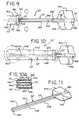
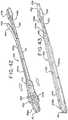
- Figs. 16 - 26illustrate another embodiment of an intermitted catheter assembly 120 comprising an elongated introducer element 122, an applicator 126 and an exemplary package 146.
- introducer element 122includes a pair of opposed members or arms 124a and 124b each extending parallel to the longitudinal axis of the introducer element 122 from a proximal insertion end 138a toward a distal end 138b thereof.
- Arms 124a and 124bdefine a slit or gap 123, and preferably a planar slit or gap, therebetween.
- a handle portion 125which includes a finger or hand gripping member 127 for gripping by a user.
- Handle portion 125includes a drainage lumen 129 therethrough which leads to a drainage opening 131 (as best shown in FIG. 26 ) for the drainage of urine.
- the introducer element 122may be formed of a flexible, shape-retaining material such as any of the materials described above with respect to introducer element 22 so it can be coiled and carried in a pocket, if desired.
- a sleeve or sheath 130 for covering or shrouding the introducer element 122is attached to applicator 126.
- applicator 126also has openings 128a and 128b for receiving arms 124a and 124b of introducer element 122.
- the first end 130a of the sleeve 130is secured to the applicator 126 about the openings 128a and 128b.
- sleeve 130is inverted at 121 ( Fig. 26 ) such that second end 130b is adjacent or near first end 130a.
- the second end 130b of sleeve 130is secured about a drainage lumen 137 of applicator 126, which lumen 137 leads to drainage opening 139 ( Fig. 18 ).
- drainage lumen 137is defined by a proximally extending stem 135 to which second end 138b of sleeve 130 is connected.
- the inverted sleeve 130defines inner 134a and outer 134b sleeve portions.
- the inner sleeve portion 134adefines a flow path 133 for passage of urine therethrough. Urine passes through flow path 133 defined by inner sleeve portion 134a and through drainage lumen 137 and drainage opening 139 of applicator 126.
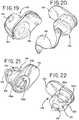
- applicator 126 and sleeve 130may be packaged in a package 146.
- Package 146includes a first or introducer opening 148 at or near the top of the package 146 wherein the opening 148 receives and retains applicator 126 when applicator 126 and package 146 are discrete individual pieces.
- applicator 126 and package 146may be formed as a single unitary structure.
- Package 146defines a cavity 150 that contains sleeve 130 in a stowed or folded configuration.
- There is a second or deployment opening 152at or near the bottom of package 146 for deployment of sleeve 130 when introducer element 120 is inserted therein.
- the packagemay also include a cover 154 that covers first and second opening 148 and 152.
- Cover 154is preferably a peelable foil that is sealed about first and second opening 148 and 152.
- cover 154includes a first portion 156 that covers opening 148 and a second portion 158 that covers opening 152.
- Cover 154also includes a section 160 between portions 156 and 158 so that both portions may be removed from the package with a single movement.
- cover 154is of a one piece construction that extends around package 146 to cover both openings 148 and 152. Other examples may include two separate covers wherein each cover covers and seals one of the openings.
- cover 154is removed from package 146 to expose openings 148 and 152.
- introducer element 122is inserted into applicator 126 and sleeve 130 to deploy sleeve 130 out of opening 152 in the bottom of package 146.
- arms 124a and 124b of introducer element 122are inserted into and through openings 128a and 128b of applicator 126 and into a space 162 ( Figs. 24 and 25 ) between inner sleeve portion 134a and outer sleeve portion 134b.
- Introducer element 122is advanced through openings 128a and 128b until the proximal insertion portion 138a of introducer element 122 is at the inverted portion 131 ( Fig. 26 ) of sleeve 130 and drainage opening 139 of applicator 126 is aligned and in abutting communication with drainage lumen 129 ( Fig. 16 ) of handle portion 125 of introducer element 122.
- Inner sleeve portion 134aseparates inner surfaces 122a of arms 124a/124b of the introducer element 122 from the urine flow path so that inner surfaces 122a of introducer element 122 are never exposed to urine during a catheterization procedure.
- outer sleeve portion 134bcovers outer surfaces 122b of arms 124a/124b of the elongated introducer element 122 to separate them from the urethra. Accordingly, the portion of the introducer element 122 which is located within the urethra during a catheterization procedure is entirely covered by the inner 134a and outer 134b sleeve portions of the sheath or sleeve 130 and is therefore suitable for reuse.
- the usermay use a gripping portion 164 ( Fig. 23 ) of package 146, such as the illustrated finger tab, and handle 125 of the introducer element 122 to assist in positioning and inserting catheter assembly 120 into the urethra.
- Catheter assembly 120is inserted through the urethra until proximal end portion 138a enters the bladder.
- Urinedrains through flow path 133 defined by inner sleeve portion 134a, lumen 137 applicator 126 ( Fig. 17 ), drainage lumen 127 and out of drainage opening 131 of handle 125 into a suitable collection receptacle. After drainage of the bladder is completed, catheter assembly 120 is retracted from the urethra.
- Introducer element 122is removed from sleeve 130 and applicator 126.
- Sleeve 130, applicator 126 and package 146are then disposed of.
- sleeve 130, applicator 126 and package 146are made of flushable materials that may be disposed of by flushing down the toilet. Such materials may be water soluble or degradable materials.
- sleeve 130 and applicator 126may be made of flushable materials and are separable from package 146.
- sleeve 130 and applicator 126may be disposed of in the toilet and package 146 is disposed of in an appropriate waste collection container.
- the introducer element 122is reusable and need not be sterile since the portion inserted into the urethra is entirely covered by the sheath 130 during a catheterization procedure.
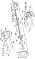
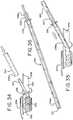
- Figs. 27 - 36illustrate yet another catheter assembly 220 of the present disclosure.
- Catheter assembly 220includes an elongated introducer element 222 (shown in Figs. 30 , 31 and 36 ), an applicator 226, sleeve 230 and, optionally, a package of 246.
- elongated introducer element 222may be formed of a flexible material and is adapted for insertion into a urethra during a catheterization procedure.
- introducer element 222has at least one slit 224 extending longitudinally along a portion of its length and preferably at least a substantial portion of its length.
- applicator 226includes a first or outer passageway 228 extending through applicator 226 and having proximal opening 228a and a distal opening 228b.
- a thin sheath, sleeve or shroud 230has a first end 230a secured to the applicator 226 about proximal opening 228a of passageway 228.
- sleeve 230is inverted about 221 ( Fig. 29 ) such that a second end 230b of sleeve 230 is adjacent or near first end 230a.
- the second end 230b of sleeve 230is secured about a drainage passageway 237 of applicator 226.
- passageways 228 and 237are defined by a proximally extending stem 235 projecting from a proximal surface 223 of applicator 226.
- Passageway 237leads to and is in fluid communication with drainage tube 227 distally extending from a distal surface 225 of applicator 226.
- Drainage tube 227includes a drainage opening 239.
- Inverted sleeve 230defines inner 234a and outer 234b sleeve portions.
- Inner sleeve portion 234adefines a flow path 233 for passage of urine therethrough. Urine passes through flow path 233 and through passageway 237, drainage tube 227 and drainage opening 239 of applicator 226.
- drainage tube 227is aligned and inserted into proximal insertion end 238a of introducer element 222.
- Drainage tube 227functions as guide member to align and guide proximal insertion end 238a of introducer element 222 to opening 228b.
- opening 228bhas the generally the same profile as introducer element 222.
- introducer element 222is inserted through passageway 228 and into the space 241 defined between inner sleeve portion 234a and outer sleeve portion 234b.
- Introducer element 222is inserted into passageway 228 until proximal insertion end reaches inverted portion 221 of sleeve 230, as illustrated in Fig. 36 .
- Inner sleeve portion 234aserves to separate and shroud an inner surface 222a ( Figs. 30 - 33 ) of the introducer element 222 from the urine flow path so that introducer element 222 is never exposed to urine during a catheterization procedure.
- outer sleeve portion 234bextends over and shrouds an outer surface 222b ( Figs. 30 - 33 ) of the elongated introducer element 222 to separate it from the urethra. Accordingly, the portion of the introducer element 222 which is located within the urethra during a catheterization procedure is entirely covered by the inner 234a and outer 234b sleeve portions of the sheath 230 and is therefore suitable for reuse.
- applicator 226 and sleeve 230may be packaged in a package 246.
- Package 246includes a first cavity 250 for containing applicator 226 and a seconded cavity 252 for containing sleeve 230 in a folded or rolled up condition.
- the package 246may include a cover or seal 254 covering the top of the package 246.
- the cover 254is a peelable seal.
- cover 254is removed from package 246 and drainage tube 227 is lifted or tilted at an angle by the user. Drainage tube 227 is aligned and inserted into the proximal insertion end 238a of introducer element 222.
- the introducer element 222is advanced and guided by drainage tube 227 into distal opening 228b of passageway 228 of applicator 226, as described above.
- Introducer element 222is advanced through passageway 228 by the user gripping and pulling applicator 226 along introducer element 222 or by continued insertion of introducer element into passageway 228 with applicator 226 is held stationary.
- Introducer element 222is advanced through passageway 228 and through the space 241 between inner and outer sleeve portions 234a/234b until the proximal insertion portion 238a of introducer element 222 reaches inverted portion 221 of sleeve 230 and drainage tube 227 of applicator 226 extends out of distal end portion 238b of introducer element 222, as illustrated in Fig. 36 .
- the usermay grip applicator 226 to assist in positioning catheter assembly 220 and inserting it into the urethra.
- Catheter assembly 220is inserted through the urethra until proximal end portion 238a enters the bladder.
- Urinedrains through flow path 231 defined by inner sleeve portion 234a and through passageway 237 and drainage tube 227 of applicator 226. Drainage tube 226 extends beyond the distal end portion 238b of introducer element 222 to reduce the chances of urine coming into contact with the distal end portion 238b of introducer element 222.
- catheter assemblyis retracted from the urethra. Introducer element 222 is removed from sleeve 230 and applicator 226.
- Sleeve 230 and applicator 226are then disposed of.
- the introducer element 222is reusable and need not be sterile since the portion inserted into the urethra is entirely covered by the sheath 230 during a catheterization procedure.
- the applicator 226 and sleeve 230may be made of flushable biodegradable materials.
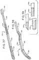
- Figs. 37 - 39disclose one embodiment of an introducer element 322 of the present disclosure, which may be used with the applicators disclosed herein. Similar to elongated introducer element 22, elongated introducer element 322 may be formed of a flexible material and is adapted for insertion into a urethra during a catheterization procedure. Introducer element 322 has at least one slit 324 extending longitudinally along a portion of its length and preferably at least a substantial portion of its length.
- Introducer element 322also may include different flexibility and stiffness characteristics along its lengths to impart varying flexibility to the introducer element 322.
- Figs. 37 and 38show introducer element 322 divided into four sections, wherein the sections have different flexibilities relative to adjacent sections.
- Introducer 322includes a first proximal section 326, a second section 328, a third section 330 and a fourth section 332.
- the first proximal section 326is configured to be inserted through the urethra and into the bladder.
- First section 326may be relatively more flexible than second section 328.
- Second section 328is positioned adjacent to and distally of first section 326 and is relatively more rigid than first section 326.
- a third section 330is positioned adjacent and distally of second section 328.
- Third section 330is relatively more flexible than second section 328 and fourth section 332, which is positioned distally of third section 330 and relatively more rigid than the third section. As illustrate in Fig. 38 , the first and third sections 326 and 330 are flexible while the second and fourth 328 and 332 are substantially rigid and remain generally linear.
- each sectionmay be varied by varying the type or thickness of the material or by creating flexure areas, such as slits or cut-outs. In some applications, varying the flexibility/rigidity of the introducer along its length assists in inserting and traversing the introducer element and sleeve through the tortuous pathway of the male urethra.
- Fig. 39illustrates some exemplary configurations of the proximal insertion end, generally designated 338, of the introducer element, generally designated 322.
- element 322aincludes an angled proximal insertion end 338a.
- Introducer elements 322b and 322cinclude more blunted proximal end insertion ends 338b and 338c, respectively.
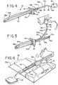
- Figs. 40 - 43illustrate another embodiment of a catheter assembly 420 of the present disclosure.
- catheter assembly 420includes an introducer element 422 and a sheath, sleeve or shroud 430.
- Sleeve 430is similar to the other sleeves described above and is formed of a thin material.
- Sleeve 430is inverted at 421 to form an inner portion 434a and an outer portion 434b.
- Inner portion 434adefines a flow path 431 having a drainage opening 432 for the passage of urine therethrough.
- a space 435 for receiving the introducer element 422is defined between inner 434a and outer 434b portions of sleeve 430.
- introducer element 422includes a proximal insertion end portion 438a and a distal end portion 438b. Introducer element 422 also includes a slit 424 at least partially along, and preferably substantially along, the entire length of introducer element 422. A handle 425 may be located at the distal end portion 438b for gripping by the user.
- the userinserts proximal insertion end 438a into the space 435 defined between inner portion 434a and outer portion 434b of sleeve 430.
- the inner portion 434amay include gripping portion 440 designated for gripping the inner portion.
- the outer portion 434balso may have a gripping portion 442 for gripping the outer portion.
- the gripping portions 440 and 442may be designated by color or texture. It is preferable for the user to use the gripping portions so that the user recognizes and utilizes the gripping portions of the sleeve to handle the sleeve. Handling the sleeve by the designated gripping portions reduces the risk of contamination of the portion of the sleeve inserted into the urethra because the portions inserted into the urethra are not contacted by the user's fingers.
- inner portion 434a of sleeve 430is gripped by the user at gripping portion 440 and pulled along the length of introducer element 422. Inner portion 434a is then or simultaneously inserted into slit 424 of introducer element 422. Referring to Fig. 42 , outer portion 434b of sleeve 430 is then gripped by gripping portion 442 and pulled along the length of introducer element 422 until outer portion 434b covers the surface of introducer element 422.
- the usermay grip handle portion 425 of introducer element 422 to insert and advance catheter 420 into and through the urethra.
- Catheter assembly 420is inserted through the urethra until proximal end portion 438a enters the bladder.
- Urinedrains through a flow path 431 defined by inner sleeve portion 434a and out of drainage opening 432 into a suitable collection receptacle. Drainage opening 432 is located beyond the distal end portion 438b of introducer element 422 to reduce the chances of urine coming into contact with the distal end portion 438b of introducer element 422. After drainage of the bladder is completed, catheter assembly is retracted from the urethra.
- Introducer element 422is removed from sleeve 430 and sleeve 430 is then disposed of.
- the introducer element 222is reusable and need not be sterile since the portion inserted into the urethra is entirely covered by the sheath 230 during a catheterization procedure.
- sleeve 430may be made of flushable biodegradable materials and disposed of in a toilet.
Landscapes
- Health & Medical Sciences (AREA)
- Life Sciences & Earth Sciences (AREA)
- Biophysics (AREA)
- Pulmonology (AREA)
- Engineering & Computer Science (AREA)
- Anesthesiology (AREA)
- Biomedical Technology (AREA)
- Heart & Thoracic Surgery (AREA)
- Hematology (AREA)
- Animal Behavior & Ethology (AREA)
- General Health & Medical Sciences (AREA)
- Public Health (AREA)
- Veterinary Medicine (AREA)
- External Artificial Organs (AREA)
- Media Introduction/Drainage Providing Device (AREA)
Description
- The present disclosure is generally directed to an intermittent catheter assembly adapted for a user to insert the catheter through the urethra to drain urine from the bladder and, more particularly, to an intermittent catheter assembly with a reusable insertion component for use with a single-use, component which may be disposable, for example, by flushing it down a toilet.
- Intermittent catheter assemblies are a good option for many users who suffer from various abnormalities of the urinary system. A common situation is where single-use, packaged, ready-to-use sterile catheters are utilized. An important criterion for single-use, ready-to-use products is that they be entirely user-friendly under a wide variety of different conditions.
- Among those requiring intermittent catheterization on a regular and recurring basis are users who lead relatively mobile lives. There has been a continuing need for improved intermittent catheter assemblies for such users so they are able to carry with them the requisite number of catheters in a convenient and discrete manner so as to be able perform self-intermittent catheterization several times per day. However, intermittent catheter assemblies that have been available for self-catheterizing have often been provided in long, narrow bulky packages.
- While it is possible in some instances to fold the packages so they can be carried in a pocket, even a single packaged intermittent catheter assembly of this type tends to be quite bulky. It is also the case that such intermittent catheter assemblies do not lend themselves to discrete disposal, and no portion of such intermittent catheter assemblies is reusable. As a result, the freedom self-catheterizing could provide has not been fully achieved due to the absence of suitable products that are disposable in a discrete manner in packages of reduced size.
- In addition, existing intermittent catheter assemblies have relatively thick-walled catheter tubes formed of polymeric materials, and they typically have been single-use items that are discarded after they are used one time. As will be appreciated, this presents a significant problem due to the large amount of waste material which is created, especially considering the number of users who perform self-intermittent catheterization multiple times per day.
- To provide an intermittent catheter assembly suitable for users having relatively normal mobility, it is important to consider various aspects of self-catheterization. These include providing catheter assemblies that will facilitate i) carrying a supply which is sufficient to permit a user to self-catheterize several times a day, ii) inserting catheter assemblies in a manner which does not compromise sterility, iii) draining urine from the human bladder in an efficient and effective manner, and iv) discretely discarding at least the portion of each of the assemblies through which urine is drained. If these aspects of self-catheterization could be addressed, a person having relatively normal mobility would be better able to live an essentially unrestricted lifestyle.
US 2006/0173422 describes an introducer apparatus having a sleeve fixation mechanism that fixes a part of a sleeve outside an elongated member, i.e. medical device, so that when the elongated member is moved in a distal direction, a distal part of the elongated member engages the sleeve and unfurls it between the outside surface of the elongated member and the inside of a bodily passage.US 5,792,114 describes an introducer for sterile insertion of catheter into urethra - having a convolutionally rearward transported shroud interposed over and between the introducer's distal portion and the body internal organ surfaces, for sterile catheter passage through the introducer and into the organ.- The invention is defined in the appended independent claim 1 and subsequent dependent claims 2-15.
- In one aspect, an intermittent catheter assembly includes an elongated introducer element that has a proximal insertion end and a distal end remote from the proximal insertion end. The elongated introducer element is formed of a flexible material adapted for insertion into a urethra during a catheterization procedure and has at least one slit extending longitudinally along at least a portion thereof. The assembly also includes a sheath having a first end and a second end being inverted relative to the first end of the sheath to define inner and outer sleeve portions and a space therebetween. The inner sleeve portion defines a flow path for urine. The elongated introducer element is disposed in the space defined between the inner and outer sleeve portions. The inner sleeve portion is extendable through the at least one slit of the elongated introducer element so as to be disposed within the elongated introducer element and cover an inner surface of the elongated introducer element. The inner sleeve portion separates the inner surface of the elongated introducer element from the urine flow path. Additionally, the outer sleeve portion extends over an outer surface of the elongated introducer element to separate the outer surface of the elongated introducer element from the urethra.
- In another example, an intermittent catheter assembly includes an elongated introducer element that has a proximal insertion end and a distal end remote from the proximal insertion end. The elongated introducer element is formed of a flexible material adapted for insertion into a urethra during a catheterization procedure. Additionally, the elongated introducer element has at least one slit extending longitudinally along at least a portion thereof. The assembly also includes an applicator that has an opening for receiving the elongated introducer element and a sheath that has a first end secured to the applicator about the opening. The sheath also has a second end that defines a discharge opening. The second end of the sheath is inverted relative to the first end of the sheath and extends into the opening of the applicator to define inner and outer sleeve portions. Additionally, the inner sleeve portion defines a flow path for urine through the discharge opening. The assembly further includes a holding element that is associated with the second end of the sheath for extending the inner sleeve portion through the at least one slit of the elongated introducer element so as to dispose the inner sleeve portion within the elongated introducer element. The inner sleeve portion covers an inner surface of the elongated introducer element to separate the inner surface of the elongated introducer element from the urine flow path. As the elongated introducer element is inserted through the opening of the applicator, the outer sleeve portion extends over an outer surface of the elongated introducer element to separate the outer surface from the urethra.
- In another example, an intermittent catheter assembly includes an elongated introducer element that has a proximal insertion end and a distal end remote from the proximal insertion end. The elongated introducer element is formed of a flexible material adapted for insertion into a urethra during a catheterization procedure. The elongated introducer element has at least one slit extending longitudinally along at least a portion thereof. The assembly also includes an applicator that has at least one opening for receiving the elongated introducer element and a drainage lumen for the drainage of urine. The assembly also includes a sheath having a first end and a second end being inverted relative to the first end of the sheath to define inner and outer sleeve portions and a space therebetween. The inner sleeve portion defines a urine flow path. The first end of the sheath is secured to the applicator about the at least one opening of the applicator. The opening of the applicator is in communication with the space defined between the inner and outer sleeve portions. The second end of the sheath is secured to the applicator about the drainage lumen wherein the urine flow path defined by the inner sleeve portion is in fluid communication with the drainage lumen of the applicator. The elongated introducer element is insertable through the opening of the applicator and into the space defined between the inner and outer sleeve portions. The outer sleeve portion extends over an outer surface of the elongated introducer element and the inner sleeve portion extends through the slit and covers an inner surface of the elongated introducer element to separate the inner surface of the elongated introducer element from the urine flow path.
- In yet another example, an intermittent catheter assembly comprising an elongated introducer element formed of a flexible material adapted for insertion into a urethra during a catheterization procedure. The introducer element has at least one slit extending longitudinally along at least a substantial portion of its length. The catheter assembly also includes an applicator having an opening, and a thin sheath having a first end is secured to the applicator about the opening. The thin sheath also has a second end defining a discharge opening which is inverted relative to the first end of the sheath and extends into the opening in the applicator to define inner and outer sleeve portions. The inner sleeve portion defines a flow path for urine through the discharge opening. The catheter assembly also includes a holding element associated with the second end of the sheath for extending the inner sleeve portion through the slit(s) to be disposed within the introducer element. This serves to separate an inner surface of the introducer element from the urine flow path so the introducer element is never exposed to urine during a catheterization procedure. The applicator receives the introducer element through the opening and extends the outer sleeve portion over an outer surface of the elongated introducer element to separate it from the urethra. Accordingly, the portion of the introducer element which is located within the urethra during a catheterization procedure is entirely covered by the inner and outer sleeve portions of the sheath and is therefore suitable for reuse.
- In an example, the introducer element comprises a tube having a single slit which extends along the entire length thereof from a proximal insertion end to a distal end remote therefrom. The proximal insertion end of the introducer element is advantageously beveled to be at other than a right angle to an axis of the introducer element to aid insertion into a urethra during a catheterization procedure. Preferably, to aid insertion into the urethra, it has been found desirable for the proximal insertion end of the introducer element to be beveled so as to be at an angle of between about 15° and about 30° to an axis of the introducer element.
- With regard to the slit extending longitudinally along at least a substantial portion of the length of the elongated introducer element, it may advantageously have a width of between about 1.0 mm and 1.5 mm. As for the applicator, it may suitably comprise a collar generally surrounding the first end of the thin sheath and also defining a stop during insertion of the elongated introducer element into a urethra.
- As for the holding element, it may advantageously comprise a cord having a first end which is attached to the second end of the thin sheath, and the cord may also have a second end with a finger grip tab attached thereto. In an alternative embodiment, the second end of the thin sheath is secured to generally diametrically opposed portions of the applicator to define the holding element which is associated with the first end of the sheath. In this embodiment, the introducer element has a pair of opposed slits extending longitudinally along a substantial portion of the introducer element from a proximal insertion end toward a distal end thereof.
- Still other features and advantages of the present disclosure will become apparent from the following specification taken in conjunction with the accompanying drawings.
Fig. 1 is a perspective view of an intermittent catheter assembly including an introducer element, an applicator, and a thin sheath in accordance with the present disclosure;Fig. 2 is a front elevational view of the catheter assembly ofFig. 1 with an inner sleeve portion of the sheath extended through a slit and disposed within the introducer element;Fig. 3 is a front elevational view of the catheter assembly ofFig. 1 with an outer sleeve portion of the sheath extended over an outer surface of the introducer element in a use position;Fig. 3A is an enlarged cross-sectional taken from the area within circle 3A ofFig. 2 ;Fig. 4 is a perspective view of the catheter assembly ofFig. 3 in which the catheter assembly is ready for insertion into the urethra to perform a catheterization procedure;Fig. 5 is a perspective view of the catheter assembly ofFig. 4 in which the inner and outer sleeve portions are being removed from the introducer element for disposal;Fig. 6 is a perspective view of an exemplary intermittent catheter assembly kit in a package containing an introducer element and a plurality of individually packaged sheaths;Fig. 7 is a top plan view of a small condom style package containing a single sheath secured to an applicator and having a holding element associated with the sheath;Fig. 7A is a top plan view similar toFig. 7 illustrating the small condom style package containing a single sheath secured to an applicator after the package has been opened;Fig. 8 is a perspective view of a single sheath secured to an applicator and having a holding element associated with the sheath after removal from the package ofFig. 7A ;Fig. 9 is a front elevational view of an alternative embodiment of an intermittent catheter assembly with an inner sleeve portion of a sheath being extended through a pair of slits in an introducer element and an outer sleeve portion being disposed over the introducer element;Fig. 10 is a front elevational view of the alternative embodiment of the intermittent catheter assembly ofFig. 9 with the inner and outer sleeve portions disposed in a use position;Fig. 10A is an enlarged cross-sectional view taken from the area within circle 10A inFig. 10 ;Fig. 11 is a perspective view of the introducer element ofFig. 9 illustrating the pair of slits diametrically opposed within and along a substantial portion of a tube;Fig. 12 is a schematic view of the inner and outer sleeves of the thin sheath ofFig. 9 before extending them by inserting the introducer element into the open space between them;Fig. 13 is a perspective view of an applicator, sheath and holding element for the intermittent catheter assembly ofFig. 9 with a peel-off lid being removed therefrom;Fig. 14 is a perspective view of the applicator, sheath and holding element after the peel-off lid has been removed therefrom ready for insertion of the introducer element;Fig. 15 is a perspective view of a package containing an exemplary introducer element and a plurality of individually packages each containing an applicator, sheath and holding element;Fig. 16 is an exploded perspective view of another catheter assembly of the present disclosure;Fig. 17 is a partial perspective view of the applicator and sleeve ofFig. 16 ;Fig 18 is another partial perspective view of the applicator and sleeve ofFig. 16 shown for another direction;Figs. 19 and 20 are perspective views of the package shown inFig. 16 ;Figs. 21 and 22 are perspective views of the package ofFig. 16 shown with the applicator and sleeve therein;Fig. 23 is perspective of the catheter assembly ofFig. 16 shown prior to insertion of the introducer element into the package;Figs. 24 and 25 are partial perspective views showing the introducer element ofFig. 16 being inserted into the applicator and sleeve;Fig. 26 is a perspective view of the catheter assembly ofFig. 16 shown with the introducer element inserted into the applicator and sleeve;Figs. 27 and 28 are perspective views of another embodiment of an applicator and sleeve shown within a package;Fig. 29 is a perspective view of the applicator shown inFig. 27 ;Figs. 30 - 33 are partial perspective views showing an introducer element being inserted into the applicator ofFig. 27 ;Figs. 34 and 35 are perspective view showing an introducer element being inserted into the applicator with the package shown inFig. 27 ;Fig. 36 is perspective view of the introducer element fully inserted into the applicator and sleeve ofFig. 27 ;Figs. 37 and 38 are perspective views of another embodiment of an introducer element of the present disclosure;Fig. 39 is a plan view of exemplary proximal insertion ends of the introducer element ofFigs. 37 and 38 ;Fig. 40 is a perspective view of another embodiment of a sleeve of the present disclosure; andFigs. 41 - 43 are perspective views of showing an introducer element being inserted into the sleeve ofFig. 40 .- In the illustrations given, and first with reference to
Figs. 1-5 , thereference numeral 20 designates generally an intermittent catheter assembly comprising anelongated introducer element 22 which may be formed of a flexible material and is adapted for insertion into a urethra during a catheterization procedure. Theintroducer element 22 has at least one slit 24 extending longitudinally along a portion of its length and preferably at least a substantial portion of its length. Thecatheter assembly 20 also includes an applicator generally designated 26 which has anopening 28, and a thin sheath, sleeve orshroud 30 having afirst end 30a is secured to theapplicator 26 about theopening 28. Thethin sheath 30 also has asecond end 30b defining adischarge opening 32 which is inverted relative to thefirst end 30a of thesheath 30 and extends into theopening 28 in theapplicator 26 to define inner 34a and outer 34b sleeve portions. Theinner sleeve portion 34a defines a flow path 33 (as illustrated inFig. 3A ) for urine through thedischarge opening 32. Thecatheter assembly 20 also includes a holdingelement 36 associated with thesecond end 30b of thesheath 30 for extending theinner sleeve portion 34a through the slit(s) such as 24 to be disposed within theintroducer element 22. This serves to separate aninner surface 22a of theintroducer element 22 from the urine flow path so theintroducer element 22 is never exposed to urine during a catheterization procedure. Theapplicator 26 receives theintroducer element 22 through theopening 28 and extends theouter sleeve portion 34b over anouter surface 22b of theelongated introducer element 22 to separate it from the urethra. Referring toFig. 3A ,sleeve 30 everts over the proximal insertion end 38 ofintroducer element 22 so that theouter sleeve portion 34b extends overouter surface 22b andinner sleeve portion 34a extends overinner surface 22a ofintroducer element 22. Accordingly, the portion of theintroducer element 22 which is located within the urethra during a catheterization procedure is entirely covered by the inner 34a and outer 34b sleeve portions of thesheath 30 and is therefore suitable for reuse, as shown inFig. 3A . - In an exemplary embodiment, the
introducer element 22 comprises a tube having asingle slit 24 which extends along the entire length thereof from aproximal insertion end 38a to adistal end 38b remote therefrom. Theproximal insertion end 38a of theintroducer element 22 may be beveled to be at other than a right angle to thelongitudinal axis 40 of theintroducer element 22 to aid insertion into a urethra during a catheterization procedure. To aid insertion into the urethra, it may be desirable for theproximal insertion end 38a of theintroducer element 22 to be beveled so as to be at an angle of between about 15° and about 30° to an axis of the introducer element. - With regard to the
slit 24 extending along thelongitudinal axis 40 for the entire length of theelongated introducer element 22, it may have a width of between about 1.0 mm and 1.5 mm. As for theapplicator 28, it may include acollar 42 surrounding thefirst end 30a of thesheath 30 and the applicator defines a stop during insertion of theintroducer element 22 into a urethra. - The holding
element 36 may comprise a cord having afirst end 36a which is attached to thesecond end 30b of thethin sheath 30, and thecord 36 may also have asecond end 36b with afinger grip tab 44 attached thereto. - The
introducer element 22 may be formed of a flexible material and is preferable formed of a flexible, shape-memory material, such as a flexible shape-memory polymer.Introducer element 22 and the other introducer elements disclosed herein may be formed, for example, from polyamides, polyvinylchloride, polypropylene, polyester, polyurethane, polyesterurethane, polyetherurethane, poly(ester-etherurethane), fluoropolymers such as, but not limited to, polyvinylidene difluoride, polyvinylidene fluoride, expanded polytetrafluoroethylene, fluorinated ethylene propylene, perfluroalkoxy and combinations of any of the above listed materials. In one embodiment, the introducer element is constructed from a material that allows the introducer element to be bent into a stowed or compact configuration so that it may be, for instance, coiled and carried in a pocket, if desired, and then changed into a generally straight or slightly curved configuration for use during catheterization. Introducer element 22 also may be reusable and need not be sterile since the portion inserted into the urethra is entirely covered by thesheath 30 during a catheterization procedure. Theapplicator 26,thin sheath 30, and holdingelement 36 may be made of biodegradable materials and, preferably, flushable biodegradable materials.Applicator 26,thin sheath 30, and holdingelement 36 may be provided in apackage 46, which also may be made of biodegradable materials, in a sterile condition for immediate use when removed (seeFigs. 7, 7A and 8 ). The other applicators, thin sheaths and packaging described herein also may be made of such biodegradable materials. Additionally,introducer element 22 and the other introducer elements described herein also may be made from such biodegradable materials, preferably flexible biodegradable materials and, more preferably, flexible shape-memory, biodegradable materials.- With regard to the foregoing, the biodegradable materials for forming the
applicator 26, thethin sheath 30, the holdingelement 36,introducer element 22 andpackage 46 may comprise any of a wide range of materials that are flushable for ease of disposal after use. Potential biodegradable polymers include, but are not limited to: polyalkenedicarboylates, poly(alkylcyanoacrylate), polyamides, polyamide-enamines, polyanhydrides, poly(ε-caprolactone), polyesters, polyesterurethane, polyetherurethane, poly(ester-etherurethane), polyglycolide, polyhydroxyalkanoates, polyhydroxybutyrate, poly(hydroxybutyrate-co-valerate), polylactide, poly(p-dioxanone), poly(trimethylene carbonate), polyureas, polyurethane, cellulose, chitin, chitosan, collagen, corn, lignin, soy protein, starch, succinic acid and sugar cane. The flushable material could also be a segmented polymer; a nondegradable polymer mixed with any of the above listed biodegradable polymers, so that at least thesheath 30 would eventually decompose into small pieces. - By providing the
applicator 26, thethin sheath 30, and the holdingelement 36 in apackage 46, it is possible to provide an exemplary flushable intermittent catheter assembly kit 48 (seeFig. 6 ) having a reusableelongated introducer element 22, and a plurality offlushable catheter elements 50 each comprising one of thepackages 46. As discussed above, each of thepackages 46 includes a single, sterile ready-to-use catheter element 50 which is comprised of anapplicator 26,thin sheath 30, and holdingelement 36. As shown inFig. 6 , thekit 48 may comprise asemi-rigid carrying case 52 formed of a paperboard material to have an openable top 52a, aholder 52b for theelongated introducer element 22, and apocket 52c for, by way of example, a dozen ready-to-use catheter elements 50 with four of each disposed in three adjacent rows within thepocket 52c. - In an alternative embodiment illustrated in
Figs. 9-12 , thesecond end 30b' of the thin sheath 30' may be secured to generally diametricallyopposed portions 46a and 46b of the applicator 26' to define the holding element which may be associated with thesecond end 30b' of the sheath 30'. With this embodiment which is discussed in detail below, the introducer element 22' includes a pair of opposed members orarms 24a' and 24b' each extending parallel to the longitudinal axis 40' of the introducer element 22' from aproximal insertion end 38a' toward adistal end 38b' thereof.Arms 24a' and 24b' define a slit or gap 23', and preferably a planar slit or gap, therebetween. - As with the earlier embodiment, the applicator 26' has an opening 28', and the
first end 30a' of the thin sheath 30' may be secured to the applicator 26' about the opening 28'. Thesecond end 30b' of the thin sheath 30' defines a discharge opening 32' which may be inverted relative to thefirst end 30a' of the sheath 30' and extends into the opening 28' in the applicator 26' to define inner 34a' and outer 34b' sleeve portions. Theinner sleeve portion 34a' defines a flow path 33' (shown inFig. 10A ) for urine through the discharge opening 32'. The catheter assembly 20 'also may include a holding element 36' (seeFig. 14 ) associated with thesecond end 30b' of the sheath 30' for theinner sleeve portion 34a' to be extended through the slit 23' defined byarms 24a' and 24b' such thatinner sleeve portion 34a' is disposed within the introducer element 22'. This serves to separateinner surfaces 22a' ofarms 24a'/24b'of the introducer element 22' from the urine flow path so the introducer element 22' is never exposed to urine during a catheterization procedure. The applicator 26' receives the introducer element 22' through the opening 28' and extends theouter sleeve portion 34b' over anouter surface 22b' of the elongated introducer element 22' to separate it from the urethra. Referring toFig. 10A , sleeve 30' everts over the proximal insertion end 38' of introducer element 22' so that theouter sleeve portion 34b' extends overouter surface 22b' andinner sleeve portion 34a' extends overinner surface 22a' of introducer element 22'. Accordingly, the portion of the introducer element 22' which is located within the urethra during a catheterization procedure is entirely covered by the inner 34a' and outer 34b' sleeve portions of the sheath 30' and is therefore suitable for reuse. - The introducer element 22' comprises a pair of opposed elements or
arms 24a' and 24b' which extend longitudinally and define a slit 23' that extends along at least a portion of the introducer element 22' and preferably from theproximal insertion end 38a' toward thedistal end 38b' of introducer element 22'. The portion of thearms 24a' and 24b' near theproximal insertion end 38a' of the introducer element 22' may be rounded, as will be appreciated by referring toFig. 11 , which will facilitate insertion into a urethra during a catheterization procedure. The elongated introducer element 22' may include a pair ofgripping elements distal end 38b' remote from theproximal insertion end 38a' beyond slit 23' (seeFigs. 9-11 ). - In addition to the foregoing, the introducer element 22' in the embodiment illustrated in
Figs, 9-11 may be formed of a flexible, shape-retaining material such as any of the materials described above with respect tointroducer element 22 so it can be coiled and carried in a pocket, if desired. As before, the introducer element 22' is reusable and need not be sterile since the portion inserted into the urethra is entirely covered by the sheath 30' during a catheterization procedure. Also, as before, the applicator 26', the thin sheath 30', and the holding element 36' may be made of flushable biodegradable materials and provided in a package 46' in a sterile condition for immediate use when removed (seeFigs. 13 and 14 ). - By providing the applicator 26', the thin sheath 30', and the holding element 36' in a package 46', it is possible to provide an exemplary flushable intermittent catheter assembly kit 48' (see
Fig. 15 ) having a reusable elongated introducer element 22', and a plurality of flushable catheter elements 50' each comprising one of the packages 46'. Each of the packages 46' includes a single, sterile ready-to-use catheter element 50' which is comprised of an applicator 26', thin sheath 30', and holding element 36'. As shown inFig. 15 , the kit 48' may comprise a semi-rigid carrying case 52' formed of paperboard material with an openable top 52a', a holder (not shown) for the introducer element (not shown), and apocket 52c' for, e.g., fifteen packages 46' of ready-to-use catheter elements (not shown), i.e., three each in five adjacent rows in thepocket 52c'. - In the exemplary use of the embodiment illustrated in
Figs. 1-5 , it will be appreciated that one of thecatheter elements 50 is first removed from one of thepackages 46 after it has been opened (Fig. 7A ), following which thegrip tab 44 is used to extend theinner sleeve portion 34a of thesheath 30 while gripping thecollar 42. When this has been done, theslit 24 is used to locate theinner sleeve portion 34a within the introducer element 22 (seeFigs. 1 and 2 ). After theinner sleeve portion 34a of thesheath 30 has been located within the introducer element 22 (seeFig. 2 ), thecollar 42 is used to extend theouter sleeve portion 34b over a substantial portion of theouter surface 22b of theintroducer element 22 to be inserted into the urethra (seeFigs. 3 and4 ). - Following a catheterization procedure, the
collar 42 and thegrip tab 44 can again be used to remove thesheath 30 from the introducer element 22 (seeFig. 5 ), and thecatheter element 50 comprised of theapplicator 26, thesheath 30 and thegrip tab 44 can be flushed down the toilet and the introducer element put away for use at a later time with a freshnew catheter element 50. - In the exemplary use of the embodiment illustrated in
Figs. 9-11 ,13 and 14 , it will be appreciated that one of the catheter elements 50' is first accessed by peeling open one of the packages 46' as shown inFig. 13 . When this has been done, thearms 24a' and 24b' of introducer element 22' are inserted through the opening 28' in the applicator 26' with the two arm portions of the disposed on opposite sides of theinner sleeve portion 34a' which is attached at generally diametricallyopposed portions 46a and 46b of the applicator 26' so theinner sleeve portion 34a' is within the introduce element 22'. Next, the introducer element 22' is fully inserted through the opening 28' in the applicator 26' causing theinner sleeve portion 34a' and theouter sleeve portion 34b' to be fully deployed (seeFig. 10 ). - Referring to
Fig. 12 , it will be noted that there areopenings arm portions 24a' and 24b' of the introducer element 22' can be inserted. As shown, the twoarms 24a' and 24b' are disposed on opposite sides of theinner sleeve portion 34a' and, as noted above, theinner sleeve portion 34a' is attached at generally diametricallyopposed portions 46a and 46b of the applicator 26'. When the introducer element 22' is further inserted, it causes theinner sleeve portion 34a' and theouter sleeve portion 34b' of the sheath 30' to "unfold" or "unroll" to cover the inner andouter surfaces 22a' and 22b'. - In the position shown in
Fig. 10 , thegripping elements Figs. 16 - 26 illustrate another embodiment of an intermittedcatheter assembly 120 comprising anelongated introducer element 122, anapplicator 126 and anexemplary package 146. Similar to elongated introducer element 22',introducer element 122 includes a pair of opposed members orarms introducer element 122 from aproximal insertion end 138a toward adistal end 138b thereof.Arms gap 123, and preferably a planar slit or gap, therebetween. At or near thedistal end 138b ofintroducer element 122 is ahandle portion 125 which includes a finger or hand grippingmember 127 for gripping by a user.Handle portion 125 includes adrainage lumen 129 therethrough which leads to a drainage opening 131 (as best shown inFIG. 26 ) for the drainage of urine. In addition to the foregoing, theintroducer element 122 may be formed of a flexible, shape-retaining material such as any of the materials described above with respect tointroducer element 22 so it can be coiled and carried in a pocket, if desired.- As with the earlier embodiments, a sleeve or
sheath 130 for covering or shrouding theintroducer element 122 is attached toapplicator 126. Referring toFigs. 17 and 18 ,applicator 126 also hasopenings arms introducer element 122. Thefirst end 130a of thesleeve 130 is secured to theapplicator 126 about theopenings sleeve 130 is inverted at 121 (Fig. 26 ) such thatsecond end 130b is adjacent or nearfirst end 130a. Thesecond end 130b ofsleeve 130 is secured about adrainage lumen 137 ofapplicator 126, which lumen 137 leads to drainage opening 139 (Fig. 18 ). In the illustrated embodiment,drainage lumen 137 is defined by aproximally extending stem 135 to whichsecond end 138b ofsleeve 130 is connected. Theinverted sleeve 130 defines inner 134a and outer 134b sleeve portions. Theinner sleeve portion 134a defines aflow path 133 for passage of urine therethrough. Urine passes throughflow path 133 defined byinner sleeve portion 134a and throughdrainage lumen 137 anddrainage opening 139 ofapplicator 126. - Turning to
Figs. 19 - 22 ,applicator 126 andsleeve 130, optionally, may be packaged in apackage 146.Package 146 includes a first orintroducer opening 148 at or near the top of thepackage 146 wherein theopening 148 receives and retainsapplicator 126 whenapplicator 126 andpackage 146 are discrete individual pieces. In some examples,applicator 126 andpackage 146 may be formed as a single unitary structure.Package 146 defines acavity 150 that containssleeve 130 in a stowed or folded configuration. There is a second ordeployment opening 152 at or near the bottom ofpackage 146 for deployment ofsleeve 130 whenintroducer element 120 is inserted therein. The package may also include acover 154 that covers first andsecond opening second opening example cover 154 includes a first portion 156 that coversopening 148 and a second portion 158 that coversopening 152. Cover 154 also includes a section 160 between portions 156 and 158 so that both portions may be removed from the package with a single movement. In the illustrated example, cover 154 is of a one piece construction that extends aroundpackage 146 to cover bothopenings - In use,
cover 154 is removed frompackage 146 to exposeopenings Figs. 23 - 26 ,introducer element 122 is inserted intoapplicator 126 andsleeve 130 to deploysleeve 130 out of opening 152 in the bottom ofpackage 146. In particular and referring toFigs. 24 - 26 ,arms introducer element 122 are inserted into and throughopenings applicator 126 and into a space 162 (Figs. 24 and 25 ) betweeninner sleeve portion 134a andouter sleeve portion 134b.Introducer element 122 is advanced throughopenings proximal insertion portion 138a ofintroducer element 122 is at the inverted portion 131 (Fig. 26 ) ofsleeve 130 anddrainage opening 139 ofapplicator 126 is aligned and in abutting communication with drainage lumen 129 (Fig. 16 ) ofhandle portion 125 ofintroducer element 122.Inner sleeve portion 134a separatesinner surfaces 122a ofarms 124a/124b of theintroducer element 122 from the urine flow path so thatinner surfaces 122a ofintroducer element 122 are never exposed to urine during a catheterization procedure. Additionally,outer sleeve portion 134b coversouter surfaces 122b ofarms 124a/124b of theelongated introducer element 122 to separate them from the urethra. Accordingly, the portion of theintroducer element 122 which is located within the urethra during a catheterization procedure is entirely covered by the inner 134a and outer 134b sleeve portions of the sheath orsleeve 130 and is therefore suitable for reuse. - The user may use a gripping portion 164 (
Fig. 23 ) ofpackage 146, such as the illustrated finger tab, and handle 125 of theintroducer element 122 to assist in positioning and insertingcatheter assembly 120 into the urethra.Catheter assembly 120 is inserted through the urethra untilproximal end portion 138a enters the bladder. Urine drains throughflow path 133 defined byinner sleeve portion 134a,lumen 137 applicator 126 (Fig. 17 ),drainage lumen 127 and out ofdrainage opening 131 ofhandle 125 into a suitable collection receptacle. After drainage of the bladder is completed,catheter assembly 120 is retracted from the urethra.Introducer element 122 is removed fromsleeve 130 andapplicator 126.Sleeve 130,applicator 126 andpackage 146 are then disposed of. In one example,sleeve 130,applicator 126 andpackage 146 are made of flushable materials that may be disposed of by flushing down the toilet. Such materials may be water soluble or degradable materials. In other embodiments,sleeve 130 andapplicator 126 may be made of flushable materials and are separable frompackage 146. In such examples,sleeve 130 andapplicator 126 may be disposed of in the toilet andpackage 146 is disposed of in an appropriate waste collection container. As before, theintroducer element 122 is reusable and need not be sterile since the portion inserted into the urethra is entirely covered by thesheath 130 during a catheterization procedure. Figs. 27 - 36 illustrate yet anothercatheter assembly 220 of the present disclosure.Catheter assembly 220 includes an elongated introducer element 222 (shown inFigs. 30 ,31 and36 ), anapplicator 226,sleeve 230 and, optionally, a package of 246. Similar toelongated introducer element 22,elongated introducer element 222 may be formed of a flexible material and is adapted for insertion into a urethra during a catheterization procedure. As shown inFigs. 30 and31 ,introducer element 222 has at least oneslit 224 extending longitudinally along a portion of its length and preferably at least a substantial portion of its length.- Turning to
Figs. 29 - 33 ,applicator 226 includes a first orouter passageway 228 extending throughapplicator 226 and havingproximal opening 228a and adistal opening 228b. A thin sheath, sleeve orshroud 230 has afirst end 230a secured to theapplicator 226 aboutproximal opening 228a ofpassageway 228. As in the previous embodiments,sleeve 230 is inverted about 221 (Fig. 29 ) such that asecond end 230b ofsleeve 230 is adjacent or nearfirst end 230a. Thesecond end 230b ofsleeve 230 is secured about adrainage passageway 237 ofapplicator 226. In the illustrated embodiment,passageways proximal surface 223 ofapplicator 226.Passageway 237 leads to and is in fluid communication withdrainage tube 227 distally extending from adistal surface 225 ofapplicator 226.Drainage tube 227 includes adrainage opening 239. Inverted sleeve 230 defines inner 234a and outer 234b sleeve portions.Inner sleeve portion 234a defines aflow path 233 for passage of urine therethrough. Urine passes throughflow path 233 and throughpassageway 237,drainage tube 227 anddrainage opening 239 ofapplicator 226.- Turning to
Figs. 30 - 31 , to insertintroducer element 222 intoapplicator 226,drainage tube 227 is aligned and inserted intoproximal insertion end 238a ofintroducer element 222.Drainage tube 227 functions as guide member to align and guideproximal insertion end 238a ofintroducer element 222 to opening 228b. In the illustrated embodiment, opening 228b has the generally the same profile asintroducer element 222. As illustrated inFigs. 32 and 33 ,introducer element 222 is inserted throughpassageway 228 and into thespace 241 defined betweeninner sleeve portion 234a andouter sleeve portion 234b.Introducer element 222 is inserted intopassageway 228 until proximal insertion end reachesinverted portion 221 ofsleeve 230, as illustrated inFig. 36 .Inner sleeve portion 234a serves to separate and shroud an inner surface 222a (Figs. 30 - 33 ) of theintroducer element 222 from the urine flow path so thatintroducer element 222 is never exposed to urine during a catheterization procedure. Additionally,outer sleeve portion 234b extends over and shrouds anouter surface 222b (Figs. 30 - 33 ) of theelongated introducer element 222 to separate it from the urethra. Accordingly, the portion of theintroducer element 222 which is located within the urethra during a catheterization procedure is entirely covered by the inner 234a and outer 234b sleeve portions of thesheath 230 and is therefore suitable for reuse. - Referring to
Figs. 27, 28 ,34 and 35 ,applicator 226 andsleeve 230, optionally, may be packaged in apackage 246.Package 246 includes afirst cavity 250 for containingapplicator 226 and a secondedcavity 252 for containingsleeve 230 in a folded or rolled up condition. Thepackage 246 may include a cover or seal 254 covering the top of thepackage 246. Preferably, thecover 254 is a peelable seal. - Referring to
Figs. 34 and 35 , in use,cover 254 is removed frompackage 246 anddrainage tube 227 is lifted or tilted at an angle by the user.Drainage tube 227 is aligned and inserted into theproximal insertion end 238a ofintroducer element 222. Theintroducer element 222 is advanced and guided bydrainage tube 227 intodistal opening 228b ofpassageway 228 ofapplicator 226, as described above.Introducer element 222 is advanced throughpassageway 228 by the user gripping and pullingapplicator 226 alongintroducer element 222 or by continued insertion of introducer element intopassageway 228 withapplicator 226 is held stationary.Introducer element 222 is advanced throughpassageway 228 and through thespace 241 between inner andouter sleeve portions 234a/234b until theproximal insertion portion 238a ofintroducer element 222 reachesinverted portion 221 ofsleeve 230 anddrainage tube 227 ofapplicator 226 extends out of distal end portion 238b ofintroducer element 222, as illustrated inFig. 36 . - The user may grip
applicator 226 to assist inpositioning catheter assembly 220 and inserting it into the urethra.Catheter assembly 220 is inserted through the urethra untilproximal end portion 238a enters the bladder. Urine drains through flow path 231 defined byinner sleeve portion 234a and throughpassageway 237 anddrainage tube 227 ofapplicator 226.Drainage tube 226 extends beyond the distal end portion 238b ofintroducer element 222 to reduce the chances of urine coming into contact with the distal end portion 238b ofintroducer element 222. After drainage of the bladder is completed, catheter assembly is retracted from the urethra.Introducer element 222 is removed fromsleeve 230 andapplicator 226.Sleeve 230 andapplicator 226 are then disposed of. As before, theintroducer element 222 is reusable and need not be sterile since the portion inserted into the urethra is entirely covered by thesheath 230 during a catheterization procedure. Also, as before, theapplicator 226 andsleeve 230 may be made of flushable biodegradable materials. Figs. 37 - 39 disclose one embodiment of anintroducer element 322 of the present disclosure, which may be used with the applicators disclosed herein. Similar toelongated introducer element 22,elongated introducer element 322 may be formed of a flexible material and is adapted for insertion into a urethra during a catheterization procedure.Introducer element 322 has at least oneslit 324 extending longitudinally along a portion of its length and preferably at least a substantial portion of its length.Introducer element 322 also may include different flexibility and stiffness characteristics along its lengths to impart varying flexibility to theintroducer element 322.Figs. 37 and 38 show introducer element 322 divided into four sections, wherein the sections have different flexibilities relative to adjacent sections.Introducer 322 includes a firstproximal section 326, asecond section 328, athird section 330 and afourth section 332. The firstproximal section 326 is configured to be inserted through the urethra and into the bladder.First section 326 may be relatively more flexible thansecond section 328.Second section 328 is positioned adjacent to and distally offirst section 326 and is relatively more rigid thanfirst section 326. Athird section 330 is positioned adjacent and distally ofsecond section 328.Third section 330 is relatively more flexible thansecond section 328 andfourth section 332, which is positioned distally ofthird section 330 and relatively more rigid than the third section. As illustrate inFig. 38 , the first andthird sections - The flexibility/rigidity of each section may be varied by varying the type or thickness of the material or by creating flexure areas, such as slits or cut-outs. In some applications, varying the flexibility/rigidity of the introducer along its length assists in inserting and traversing the introducer element and sleeve through the tortuous pathway of the male urethra.
Fig. 39 illustrates some exemplary configurations of the proximal insertion end, generally designated 338, of the introducer element, generally designated 322. For example,element 322a includes an angledproximal insertion end 338a.Introducer elements Figs. 40 - 43 illustrate another embodiment of acatheter assembly 420 of the present disclosure. As illustrated inFigs. 40 and 41 ,catheter assembly 420 includes anintroducer element 422 and a sheath, sleeve orshroud 430.Sleeve 430 is similar to the other sleeves described above and is formed of a thin material.Sleeve 430 is inverted at 421 to form aninner portion 434a and anouter portion 434b.Inner portion 434a defines aflow path 431 having adrainage opening 432 for the passage of urine therethrough. As will be explained in more detail below, aspace 435 for receiving theintroducer element 422 is defined between inner 434a and outer 434b portions ofsleeve 430.- As shown in
figures 41 - 43 ,introducer element 422 includes a proximalinsertion end portion 438a and adistal end portion 438b.Introducer element 422 also includes aslit 424 at least partially along, and preferably substantially along, the entire length ofintroducer element 422. Ahandle 425 may be located at thedistal end portion 438b for gripping by the user. - In an exemplary use, the user inserts
proximal insertion end 438a into thespace 435 defined betweeninner portion 434a andouter portion 434b ofsleeve 430. Theinner portion 434a may include grippingportion 440 designated for gripping the inner portion. Similarly, theouter portion 434b also may have agripping portion 442 for gripping the outer portion. The grippingportions - After the
proximal insertion end 438a has been inserted intospace 435,inner portion 434a ofsleeve 430 is gripped by the user at grippingportion 440 and pulled along the length ofintroducer element 422.Inner portion 434a is then or simultaneously inserted intoslit 424 ofintroducer element 422. Referring toFig. 42 ,outer portion 434b ofsleeve 430 is then gripped by grippingportion 442 and pulled along the length ofintroducer element 422 untilouter portion 434b covers the surface ofintroducer element 422. - The user may grip handle
portion 425 ofintroducer element 422 to insert andadvance catheter 420 into and through the urethra.Catheter assembly 420 is inserted through the urethra untilproximal end portion 438a enters the bladder. Urine drains through aflow path 431 defined byinner sleeve portion 434a and out ofdrainage opening 432 into a suitable collection receptacle.Drainage opening 432 is located beyond thedistal end portion 438b ofintroducer element 422 to reduce the chances of urine coming into contact with thedistal end portion 438b ofintroducer element 422. After drainage of the bladder is completed, catheter assembly is retracted from the urethra.Introducer element 422 is removed fromsleeve 430 andsleeve 430 is then disposed of. As before, theintroducer element 222 is reusable and need not be sterile since the portion inserted into the urethra is entirely covered by thesheath 230 during a catheterization procedure. Also as before,sleeve 430 may be made of flushable biodegradable materials and disposed of in a toilet. - While in the foregoing there have been set forth different embodiments of the disclosure, it will be appreciated that they have been provided for purposes of illustration only and the disclosure is not limited to these embodiments but is only limited to what falls within the scope of the appended claims.
Claims (15)
- An intermittent catheter assembly (20), comprising:an elongated introducer element (22) having a proximal insertion end and a distal end remote from the proximal insertion end, the elongated introducer element being formed of a flexible material adapted for insertion into a urethra during a catheterization procedure, the elongated introducer element having at least one slit (24) extending longitudinally along at least a portion of the elongated introducer element;a sheath (30) having a first end (30a) and a second end (30b) being inverted relative to the first end of the sheath to define inner (34a) and outer (34b) sleeve portions and a space therebetween, the inner sleeve portion defining a flow path for urine;the elongated introducer element being disposed in the space defined between the inner and outer sleeve portions, the inner sleeve portion being extendable through the at least one slit of the elongated introducer element so as to be disposed within the elongated introducer element and cover an inner surface of the elongated introducer element to thereby separate the inner surface of the elongated introducer element from the urine flow path, and the outer sleeve portion extending over an outer surface of the elongated introducer element to thereby separate the outer surface of the elongated introducer element from the urethra.
- The intermittent catheter assembly of claim 1 further including a holding element (36) associated with the second end of the sheath for extending the inner sleeve portion through the at least one slit of the elongated introducer element.
- The intermittent catheter assembly of claim 2 wherein the holding element comprises a cord having a first end attached to the second end of the sheath, the cord also having a second end with a finger grip tab attached thereto.
- The intermittent catheter assembly of any one of the preceding claims further including an applicator (26) having at least one opening (28) for receiving the elongated introducer element therethrough, and the first end of the sheath being secured to the applicator about the at least one opening.
- The intermittent catheter assembly of claim 4 wherein the applicator comprises a collar generally surrounding the first end of the sheath and defines a stop during insertion of the elongated introducer element into a urethra.
- The intermittent catheter assembly of claim 4 wherein the second end of the sheath is secured to generally diametrically opposed portions of the applicator.
- The intermittent catheter assembly of claim 4 wherein the applicator includes a drainage lumen wherein the second end of the sheath is secured about the drainage lumen so that the urine flow path defined by the inner sleeve portion is in fluid communication with the drainage lumen.
- The intermittent catheter assembly of claim 7 wherein the drainage lumen is at least partially defined by a drainage tube that extends distally from a distal surface of the applicator.
- The intermittent catheter of claim 8 wherein the drainage tube functions as a guide for guiding insertion of the elongated introducer element into the at least one opening of the applicator.
- The intermittent catheter assembly of any one of claims 4 - 9 wherein the applicator includes two openings for receiving the elongated introducer element and the elongated introducer element includes a pair of opposed arms wherein each arm is received into one of the openings and into the space defined between the outer and inner sleeve portions.
- The intermittent catheter assembly of any one of claims 1 - 9 wherein the elongated introducer element comprises a tube having a single slit extending along the entire length thereof from the proximal insertion end to the distal end.
- The intermittent catheter assembly of any one of the preceding claims wherein the proximal insertion end of the elongated introducer element is beveled to be at other than a right angle to an axis of the elongated introducer element to aid insertion into a urethra during a catheterization procedure.
- The intermittent catheter assembly of any one of the preceding claims wherein the proximal insertion end of the elongated introducer element is beveled so as to be at an angle of between about 15° and about 30° to an axis of the elongated introducer element.
- The intermittent catheter assembly of any one of claims 1 - 9 and 12 - 13 wherein the elongated introducer element includes opposed elongated arms defining the slit therebetween.
- The intermittent catheter assembly of any one of the preceding claims wherein the sheath is formed of a flushable material.
Applications Claiming Priority (2)
| Application Number | Priority Date | Filing Date | Title |
|---|---|---|---|
| US201261725311P | 2012-11-12 | 2012-11-12 | |
| PCT/US2013/031230WO2014074147A1 (en) | 2012-11-12 | 2013-03-14 | Intermittent catheter assembly and kit |
Publications (2)
| Publication Number | Publication Date |
|---|---|
| EP2916901A1 EP2916901A1 (en) | 2015-09-16 |
| EP2916901B1true EP2916901B1 (en) | 2020-06-24 |
Family
ID=48050905
Family Applications (1)
| Application Number | Title | Priority Date | Filing Date |
|---|---|---|---|
| EP13715036.3AActiveEP2916901B1 (en) | 2012-11-12 | 2013-03-14 | Intermittent catheter assembly |
Country Status (9)
| Country | Link |
|---|---|
| US (1) | US9925355B2 (en) |
| EP (1) | EP2916901B1 (en) |
| AU (1) | AU2013341731B2 (en) |
| CA (1) | CA2891118C (en) |
| DK (1) | DK2916901T3 (en) |
| ES (1) | ES2817789T3 (en) |
| HU (1) | HUE050969T2 (en) |
| LT (1) | LT2916901T (en) |
| WO (1) | WO2014074147A1 (en) |
Cited By (3)
| Publication number | Priority date | Publication date | Assignee | Title |
|---|---|---|---|---|
| US11135084B2 (en) | 2017-11-09 | 2021-10-05 | 11 Health And Technologies Limited | Ostomy monitoring system and method |
| USD935477S1 (en) | 2018-11-08 | 2021-11-09 | 11 Health And Technologies Limited | Display screen or portion thereof with graphical user interface |
| US12357494B2 (en) | 2020-10-15 | 2025-07-15 | Convatec Technologies Inc. | Ostomy systems and methods |
Families Citing this family (31)
| Publication number | Priority date | Publication date | Assignee | Title |
|---|---|---|---|---|
| WO2009135141A1 (en) | 2008-05-01 | 2009-11-05 | Bristol-Myers Squibb Company | Rectal drain appliance |
| CN108578044A (en) | 2011-03-17 | 2018-09-28 | 康沃特克科技公司 | High barrier elastomer excrement conduit or ostomy bag |
| PL3027266T3 (en) | 2013-08-01 | 2023-09-04 | Convatec Technologies Inc. | Self-closing bag connector |
| CA2917047C (en) | 2013-08-30 | 2019-06-11 | Hollister Incorporated | Device for trans-anal irrigation |
| AU2015204805B2 (en)* | 2014-01-09 | 2018-10-25 | Hollister Incorporated | Catheter cartridge assemblies and methods of using the same for intermittent catheterization |
| CA3217507A1 (en) | 2014-05-30 | 2015-12-03 | Hollister Incorporated | Flip open catheter package |
| US10765796B2 (en) | 2014-07-08 | 2020-09-08 | Hollister Incorporated | Trans anal irrigation platform with bed module |
| DK3166661T3 (en) | 2014-07-08 | 2019-04-23 | Hollister Inc | Portable transanal flushing device |
| JP6386858B2 (en)* | 2014-09-30 | 2018-09-05 | テルモ株式会社 | Medical long body insertion aid and medical long body set |
| HUE052247T2 (en)* | 2015-06-15 | 2021-04-28 | Hollister Inc | Urinary catheters having limited reusability |
| US11103676B2 (en) | 2016-04-22 | 2021-08-31 | Hollister Incorporated | Medical device package with flip cap having a snap fit |
| AU2017254706B2 (en) | 2016-04-22 | 2022-04-28 | Hollister Incorporated | Medical device package with a twist cap |
| JP6821779B2 (en) | 2016-07-08 | 2021-01-27 | ホリスター・インコーポレイテッドHollister Incorporated | Transanal enema therapy device |
| US11497844B2 (en) | 2016-12-14 | 2022-11-15 | Hollister Incorporated | Transanal irrigation device and system |
| WO2018156589A2 (en) | 2017-02-21 | 2018-08-30 | Hollister Incorporated | Medical device package with flip cap having a snap fit |
| KR101968602B1 (en)* | 2017-04-28 | 2019-04-15 | 주식회사 에스앤지바이오텍 | Drainage catheter |
| US11376395B2 (en)* | 2017-07-12 | 2022-07-05 | Hollister Incorporated | Ready-to-use urinary catheter assembly |
| CA3079893A1 (en) | 2017-10-25 | 2019-05-02 | Hollister Incorporated | Caps for catheter packages |
| WO2019092686A1 (en) | 2017-11-13 | 2019-05-16 | Teleflex Life Sciences Unlimited Company | Frictionless catheter |
| US11666730B2 (en) | 2017-12-08 | 2023-06-06 | Hollister Incorporated | Package for medical device for ergonomic device removal |
| GB201721956D0 (en) | 2017-12-27 | 2018-02-07 | Convatec Ltd | Female catheter locator tip |
| GB201721955D0 (en) | 2017-12-27 | 2018-02-07 | Convatec Ltd | Catheter wetting devices |
| US11931524B2 (en) | 2019-02-25 | 2024-03-19 | Coloplast A/S | Urinary catheterisation aid |
| JP7348961B2 (en)* | 2019-05-15 | 2023-09-21 | テレフレックス、ライフ、サイエンシーズ、アンリミテッド、カンパニー | catheter assembly |
| CA3140906A1 (en) | 2019-06-11 | 2020-12-17 | Convatec Technologies Inc. | Urine collection bags for use with catheter products, kits incorporating the same, and methods therefor |
| US11752298B2 (en) | 2019-12-15 | 2023-09-12 | Advocath LLC | Self-intermittent urinary catheter extension with infection detection, a catheter assembly having an extension with infection detection and a catheter assembly having infection detection |
| US11752299B2 (en) | 2019-12-15 | 2023-09-12 | Advocath LLC | Self-intermittent urinary catheter extension with infection detection, a catheter assembly having an extension with infection detection and a catheter assembly having infection detection |
| US12239764B2 (en) | 2020-03-13 | 2025-03-04 | Hollister Incorporated | Urinary catheters with improved shape recovery and ease of use |
| US12433709B2 (en) | 2020-09-04 | 2025-10-07 | Hollister Incorporated | Medical device package with first use indicator label |
| WO2025101876A2 (en)* | 2023-11-10 | 2025-05-15 | W. L. Gore & Associates, Inc. | Introducer sheath |
| WO2025188645A1 (en)* | 2024-03-04 | 2025-09-12 | Hollister Incorporated | Internal roll introducer tip |
Family Cites Families (186)
| Publication number | Priority date | Publication date | Assignee | Title |
|---|---|---|---|---|
| US3084693A (en)* | 1961-07-31 | 1963-04-09 | Edward R Cathcart | Aseptic catheter |
| US3332424A (en)* | 1965-02-03 | 1967-07-25 | Discon Corp | Extroversive catheter |
| US3583391A (en)* | 1968-11-21 | 1971-06-08 | American Hospital Supply Corp | Medical instrument with outrolling catheter |
| US3621848A (en) | 1969-11-17 | 1971-11-23 | George J Magovern | Surgical drainage tube having removable liners |
| US3702610A (en) | 1971-04-29 | 1972-11-14 | Kimberly Clark Co | Flushable web containing flushability indicator, and absorbent pads wrapped therewith |
| US3861396A (en) | 1973-08-08 | 1975-01-21 | Hydro Med Sciences Inc | Drainage tube |
| US3894540A (en) | 1973-10-09 | 1975-07-15 | Bonner F J Jun | Catheter |
| US3908663A (en)* | 1974-01-30 | 1975-09-30 | Nicholas F Viek | Catheter |
| US4100309A (en) | 1977-08-08 | 1978-07-11 | Biosearch Medical Products, Inc. | Coated substrate having a low coefficient of friction hydrophilic coating and a method of making the same |
| DE2960701D1 (en) | 1978-09-21 | 1981-11-19 | Intermedicat Gmbh | Multilayer sheet disintegratable in an aqueous medium, and vessel and bag made from this sheet |
| US4227533A (en) | 1978-11-03 | 1980-10-14 | Bristol-Myers Company | Flushable urinary catheter |
| GB2083762B (en) | 1980-08-12 | 1985-02-20 | Enak Ltd | Wc disposable sheet material and containers made therefrom |
| US4413986A (en) | 1980-11-10 | 1983-11-08 | Jacobs Henry R | Tampon assembly with means for sterile insertion |
| US4465481A (en) | 1981-02-26 | 1984-08-14 | Innovative Surgical Products, Inc. | Single piece wound drain catheter |
| AU566085B2 (en) | 1984-06-04 | 1987-10-08 | Terumo Kabushiki Kaisha | Medical instrument with surface treatment |
| US4883699A (en) | 1984-09-21 | 1989-11-28 | Menlo Care, Inc. | Polymeric article having high tensile energy to break when hydrated |
| JPS61209655A (en) | 1985-03-13 | 1986-09-17 | 株式会社 日本メデイカル・サプライ | Urine guide tube |
| US4790817A (en) | 1985-03-28 | 1988-12-13 | Luther Medical Products, Inc. | Assembly of stylet and catheter, and needle and catheter |
| US4610671A (en) | 1985-03-28 | 1986-09-09 | Luther Medical Products, Inc. | Assembly of stylet and catheter |
| US4668221A (en) | 1985-03-28 | 1987-05-26 | Luther Medical Products, Inc. | Assembly of stylet and catheter |
| US4601713A (en)* | 1985-06-11 | 1986-07-22 | Genus Catheter Technologies, Inc. | Variable diameter catheter |
| US4906238A (en) | 1985-10-15 | 1990-03-06 | Albert R. Greenfeld | Exterior antimigration refinements for self-cleaning indwelling therapeutic articles |
| GB2185404B (en) | 1986-01-17 | 1989-10-25 | Smiths Industries Plc | Wc disposable bags |
| US4795439A (en) | 1986-06-06 | 1989-01-03 | Edward Weck Incorporated | Spiral multi-lumen catheter |
| US4762738A (en) | 1986-12-22 | 1988-08-09 | E. R. Squibb & Sons, Inc. | Means for disposal of articles by flushing and ostomy pouches particularly suited for such disposal |
| US4952359A (en) | 1987-02-06 | 1990-08-28 | Becton, Dickinson And Company | Method for making splittable catheter |
| US4790831A (en) | 1987-03-30 | 1988-12-13 | Baxter Travenol Laboratories, Inc. | Torque-control catheter |
| US4769005A (en) | 1987-08-06 | 1988-09-06 | Robert Ginsburg | Selective catheter guide |
| US4840622A (en) | 1987-10-06 | 1989-06-20 | Menlo Care, Inc. | Kink resistant catheter |
| JPH0634817B2 (en) | 1987-11-25 | 1994-05-11 | ユニチカ株式会社 | Method for manufacturing antibacterial urinary catheter |
| CA1330285C (en) | 1987-12-22 | 1994-06-21 | Geoffrey S. Martin | Triple lumen catheter |
| GB8729977D0 (en) | 1987-12-23 | 1988-02-03 | Bard Ltd | Catheter |
| US4994047A (en) | 1988-05-06 | 1991-02-19 | Menlo Care, Inc. | Multi-layer cannula structure |
| US4954129A (en) | 1988-07-25 | 1990-09-04 | Abbott Laboratories | Hydrodynamic clot flushing |
| JPH0643439B2 (en) | 1989-02-07 | 1994-06-08 | 雪印乳業株式会社 | Method for oxidation of 6β-hydroxyl group of 6β, 14α-dihydroxy-4-androstene-3,17-dione by light |
| US5009648A (en) | 1989-03-22 | 1991-04-23 | E. R. Squibb & Sons, Inc. | Starch containing film ostomy pouches |
| DE69002295T2 (en) | 1989-09-25 | 1993-11-04 | Schneider Usa Inc | MULTILAYER EXTRUSION AS A METHOD FOR PRODUCING BALLOONS FOR VESSEL PLASTICS. |
| US5002526A (en) | 1989-12-22 | 1991-03-26 | Kimberly-Clark Corporation | Tampon applicator |
| US5102401A (en) | 1990-08-22 | 1992-04-07 | Becton, Dickinson And Company | Expandable catheter having hydrophobic surface |
| US5089535A (en) | 1990-10-22 | 1992-02-18 | Sealed Air Corporation | Thermoplastic compositions for water soluble foams |
| US5439454A (en) | 1992-05-14 | 1995-08-08 | Baxter International Inc. | Coextruded medical grade port tubing |
| EP0613672A1 (en) | 1993-03-01 | 1994-09-07 | Tambrands, Inc. | Water-soluble tampon applicator |
| JP3243334B2 (en) | 1993-06-10 | 2002-01-07 | テルモ株式会社 | Hydroxyalkanoate polymer composition |
| US5468526A (en) | 1993-09-20 | 1995-11-21 | The Dow Chemical Company | Multilayer barrier film for ostomy applications |
| JP3394327B2 (en) | 1994-07-11 | 2003-04-07 | テルモ株式会社 | Tube inner surface treatment method |
| CN1056117C (en) | 1994-08-30 | 2000-09-06 | 中国康复研究中心 | High hydrated elastomer formation such as catheter and making method thereof |
| US5569219A (en) | 1994-09-13 | 1996-10-29 | Hakki; A-Hamid | Collapsible catheter |
| US5676688A (en)* | 1995-02-06 | 1997-10-14 | Rtc, Inc. | Variably inflatable medical device |
| US5616126A (en) | 1995-03-03 | 1997-04-01 | Malekmehr; Farshad | Low residual bladder catheter |
| US5601538A (en) | 1995-03-07 | 1997-02-11 | Medtronic, Inc. | Flow directed catheter with hydrophilic distal end |
| EP0836500B1 (en) | 1995-06-08 | 2002-11-13 | ENGINEERS & DOCTORS A/S | Catheter with an opening/closing mechanism |
| US6849069B1 (en) | 1995-11-07 | 2005-02-01 | Boston Scientitfic Corporation | Medical device with tail(s) for assisting flow of urine |
| CN2240371Y (en) | 1995-11-15 | 1996-11-20 | 李栋 | Disposable solubility catheter |
| EP0900051A1 (en) | 1996-05-08 | 1999-03-10 | Salviac Limited | An occluder device |
| US6083230A (en) | 1997-07-30 | 2000-07-04 | Allergan | Method for making IOL insertion apparatus |
| US6017334A (en) | 1996-10-03 | 2000-01-25 | Board Of Regents, The University Of Texas System | Modified surfaces resistant to bacterial colonization |
| US5800412A (en) | 1996-10-10 | 1998-09-01 | Sts Biopolymers, Inc. | Hydrophilic coatings with hydrating agents |
| US6071618A (en) | 1996-10-11 | 2000-06-06 | Cryovac, Inc. | Process for increasing the solubility rate of a water soluble film |
| US5776611A (en) | 1996-11-18 | 1998-07-07 | C.R. Bard, Inc. | Crosslinked hydrogel coatings |
| AU734209B2 (en) | 1996-11-27 | 2001-06-07 | Coloplast A/S | An irrigation device |
| US5792114A (en)* | 1996-12-16 | 1998-08-11 | Fiore; John M. | Introducer for sterile insertion of catheter |
| AU5522798A (en) | 1996-12-31 | 1998-07-31 | Kimberly-Clark Worldwide, Inc. | Water-responsive polymer compositions and method of making the same |
| US5804653A (en) | 1997-03-07 | 1998-09-08 | Playtex Products, Inc. | Polyvinyl alcohol compound |
| US6213990B1 (en) | 1997-04-23 | 2001-04-10 | Heinz Roempke | Urine and excreta disposal device and method of use |
| GB9708783D0 (en) | 1997-04-30 | 1997-06-25 | Smiths Industries Plc | Medico-surgical bags |
| JP4316683B2 (en) | 1997-06-20 | 2009-08-19 | コロプラスト アクティーゼルスカブ | Hydrophilic coating and method for producing the same |
| US6030369A (en) | 1997-07-03 | 2000-02-29 | Target Therapeutics Inc. | Micro catheter shaft |
| JP3815526B2 (en) | 1997-11-19 | 2006-08-30 | 株式会社カネカ | Catheter tube and catheter using the same |
| US6090075A (en) | 1998-03-31 | 2000-07-18 | House; Jamie Glen | Disposable urinary catheterization assembly |
| US6627586B1 (en) | 1998-07-08 | 2003-09-30 | The Procter & Gamble Company | Cleansing compositions |
| US7141246B2 (en) | 1998-10-07 | 2006-11-28 | Sherwood Services Ag | Lubricious coating |
| CA2368470C (en) | 1999-03-25 | 2011-05-17 | Metabolix, Inc. | Medical devices and applications of polyhydroxyalkanoate polymers |
| KR100321647B1 (en) | 1999-04-01 | 2002-01-23 | 윤율로 | A decomposable ureter stent in a living body, and a process for preparing the same. |
| US6471684B2 (en) | 1999-04-30 | 2002-10-29 | Appied Medical Resources Corporation | Ureteral access sheath |
| US6673053B2 (en) | 1999-05-07 | 2004-01-06 | Scimed Life Systems, Inc. | Hydrophilic lubricity coating for medical devices comprising an antiblock agent |
| US6585721B2 (en)* | 1999-05-10 | 2003-07-01 | John M Fiore | Catheter shroud with conduit, collector and improvements |
| US6217569B1 (en) | 1999-05-10 | 2001-04-17 | John M. Fiore | Integral shroud-collector for urinary catheter |
| EP1470794A2 (en) | 1999-06-22 | 2004-10-27 | ContiCare Medical, Inc. | Self-cleansing bladder drainage device |
| AU6519100A (en) | 1999-08-05 | 2001-03-05 | Biocardia, Inc. | A system and method for delivering thermally sensitive and reverse-thermal gelation matrials |
| AU1235501A (en) | 1999-10-28 | 2001-05-08 | Regents Of The University Of California, The | Catalysts for lean burn engine exhaust abatement |
| US6579484B1 (en) | 1999-12-16 | 2003-06-17 | Advanced Cardiovascular Systems, Inc. | Co-extruded taper shaft |
| US6338739B1 (en) | 1999-12-22 | 2002-01-15 | Ethicon, Inc. | Biodegradable stent |
| US6447835B1 (en) | 2000-02-15 | 2002-09-10 | Scimed Life Systems, Inc. | Method of coating polymeric tubes used in medical devices |
| US6263519B1 (en) | 2000-04-07 | 2001-07-24 | Arichell Technologies, Inc. | Automatic tank-type flusher |
| WO2001083017A1 (en)* | 2000-05-02 | 2001-11-08 | Wilson-Cook Medical, Inc. | Introducer device for catheters o.t.l. with eversible sleeve |
| US20030187368A1 (en) | 2000-06-12 | 2003-10-02 | Masataka Sata | Medical guide wire doubling as a catheter |
| US6976973B1 (en) | 2000-10-12 | 2005-12-20 | Baxter International Inc. | Peritoneal dialysis catheters |
| US6946174B1 (en) | 2000-10-12 | 2005-09-20 | Boston Scientific Scimed, Inc. | Moisture curable balloon materials |
| US7077829B2 (en) | 2001-01-09 | 2006-07-18 | Rex Medical, L.P. | Dialysis catheter |
| JP2002360700A (en) | 2001-06-04 | 2002-12-17 | Japan Lifeline Co Ltd | Method of manufacturing balloon catheter and balloon for balloon catheter |
| US7682353B2 (en) | 2001-06-29 | 2010-03-23 | Coloplast A/S | Catheter device |
| US20030009151A1 (en) | 2001-07-03 | 2003-01-09 | Scimed Life Systems, Inc. | Biaxially oriented multilayer polymer tube for medical devices |
| US6675809B2 (en) | 2001-08-27 | 2004-01-13 | Richard S. Stack | Satiation devices and methods |
| JP2005511144A (en) | 2001-12-03 | 2005-04-28 | シー・アール・バード・インク | Microbial-resistant medical device, microbial-resistant polymer coating and production method thereof |
| US6713140B2 (en) | 2001-12-21 | 2004-03-30 | Kimberly-Clark Worldwide, Inc. | Latently dispersible barrier composite material |
| US20030228434A1 (en) | 2002-02-04 | 2003-12-11 | Upchurch Scientific, Inc. | Multilayered polymer tubing and methods of making and using same |
| US20030165647A1 (en) | 2002-03-04 | 2003-09-04 | Terumo Kabushiki Kaisha | Medical tubing and extrusion die for producing the same |
| US6942635B2 (en) | 2002-04-04 | 2005-09-13 | Angiodynamics, Inc. | Blood treatment catheter and method |
| US20040220550A1 (en) | 2002-05-24 | 2004-11-04 | Charles Schryver | Hybrid extruded articles and method |
| WO2004012590A1 (en)* | 2002-08-06 | 2004-02-12 | Atropos Limited | Evertable insertion tube for colonoscope |
| US20070043333A1 (en) | 2002-10-03 | 2007-02-22 | Scimed Life Systems, Inc. | Method for forming a medical device with a polymer coated inner lumen |
| EP1415671A1 (en) | 2002-11-01 | 2004-05-06 | Polyganics B.V. | Biodegradable drains for medical applications |
| US20040122382A1 (en) | 2002-12-23 | 2004-06-24 | Kimberly-Clark Worldwide, Inc. | Elastomeric articles with beneficial coating on a surface |
| US6960224B2 (en) | 2003-01-22 | 2005-11-01 | Cardia, Inc. | Laminated sheets for use in a fully retrievable occlusion device |
| WO2004091711A2 (en) | 2003-04-15 | 2004-10-28 | Sda Product, Inc. | Dialysis catheter system |
| US7201745B2 (en) | 2003-05-13 | 2007-04-10 | Boston Scientific Scimed, Inc. | Anti-infective central venous catheter with diffusion barrier layer |
| US20050049577A1 (en) | 2003-06-20 | 2005-03-03 | Robert Snell | Medical device |
| US7166099B2 (en) | 2003-08-21 | 2007-01-23 | Boston Scientific Scimed, Inc. | Multilayer medical devices |
| US20050109648A1 (en) | 2003-10-30 | 2005-05-26 | Hollister Incorporated | No-touch packaging configurations and application methods for hydrophilic intermittent catheters |
| US20050148512A1 (en) | 2003-11-10 | 2005-07-07 | Angiotech International Ag | Medical implants and fibrosis-inducing agents |
| US7780973B2 (en) | 2003-12-15 | 2010-08-24 | Ethicon Endo-Surgery, Inc. | Method and device for minimally invasive implantation of biomaterial |
| CA2554424A1 (en) | 2004-01-26 | 2005-08-11 | Control Delivery Systems, Inc. | Controlled and sustained delivery of nucleic acid-based therapeutic agents |
| US20050197627A1 (en) | 2004-03-05 | 2005-09-08 | Percutaneous Systems, Inc. | Method and system for deploying protective sleeve in intraluminal catherization and dilation |
| US20050218154A1 (en) | 2004-03-24 | 2005-10-06 | Selsby Adam B | Low Profile Fluid Container |
| EP1737387B1 (en) | 2004-04-02 | 2009-09-16 | Arterial Remodelling Technologies Inc. | Polymer-based stent assembly |
| US8992454B2 (en) | 2004-06-09 | 2015-03-31 | Bard Access Systems, Inc. | Splitable tip catheter with bioresorbable adhesive |
| WO2006002103A2 (en) | 2004-06-22 | 2006-01-05 | Longwater Medical, Llc (A Georgia Us Limited Liability Company) | Catheter assembly with degradable material |
| US7789873B2 (en) | 2004-08-02 | 2010-09-07 | Coloplast A/S | Urinary catheter assembly |
| WO2006037157A1 (en) | 2004-10-05 | 2006-04-13 | Plantic Technologies Ltd | Mouldable biodegradable polymer |
| US7255687B2 (en)* | 2004-11-19 | 2007-08-14 | Percutaneous Systems, Inc. | Systems and methods for luminal access |
| US8143368B2 (en) | 2004-12-23 | 2012-03-27 | Massachusetts Institute Of Technology | Disposable medical supplies from hydrolytically biodegradable plastics |
| US8697205B2 (en) | 2005-05-17 | 2014-04-15 | St. Jude Medical Ab | Elastomeric tube and method of making same |
| US20100137743A1 (en) | 2005-07-05 | 2010-06-03 | C. R. Bard, Inc. | Multi-functional and modular urine collection system |
| US7931630B2 (en) | 2005-07-05 | 2011-04-26 | C. R. Bard, Inc. | Multi-functional and modular urine collection system |
| WO2007005851A2 (en) | 2005-07-05 | 2007-01-11 | C.R. Bard, Inc. | Multi-functional and modular urine collection system |
| ES2392497T3 (en) | 2005-07-18 | 2012-12-11 | Dentsply Ih Ab | Urinary catheter |
| EP1922105A4 (en) | 2005-08-17 | 2010-07-28 | Colorado Catheter Company Inc | Catheterization assembly |
| EP1926509B1 (en) | 2005-09-21 | 2012-01-11 | SurModics, Inc. | Coatings and articles including natural biodegradable polysaccharides |
| WO2007065720A2 (en) | 2005-12-09 | 2007-06-14 | Dsm Ip Assets B.V. | Hydrophilic coating composition for urinary catheter |
| US7641757B2 (en) | 2006-01-12 | 2010-01-05 | Pacesetter, Inc. | Method of making a tubular body for a catheter, sheath or lead |
| WO2007089784A2 (en) | 2006-02-01 | 2007-08-09 | Hollister Incorporated | Methods of applying a hydrophilic coating to a substrate, and substrates having a hydrophilic coating |
| AU2007220511A1 (en) | 2006-03-01 | 2007-09-07 | Coloplast A/S | Urisheath with moulded unrolling strip |
| US8317775B2 (en) | 2006-03-10 | 2012-11-27 | Adapta Medical, Inc. | Urinary catheterization assembly with vented sheath |
| US7662146B2 (en) | 2006-03-10 | 2010-02-16 | Colorado Catheter Company, Inc. | Indwelling urinary catheterization assembly |
| DE102006020035A1 (en) | 2006-04-26 | 2007-10-31 | B. Braun Melsungen Ag | Preparation and use of poly (hydroxyethyl starch) chitin and poly (carboxymethyl starch) chitin compounds |
| US20080097620A1 (en) | 2006-05-26 | 2008-04-24 | Nanyang Technological University | Implantable article, method of forming same and method for reducing thrombogenicity |
| EP2026846A4 (en) | 2006-06-05 | 2010-09-29 | Bactiguard Ab | A polymer matrix, uses thereof and a method of manufacturing the same |
| EP2037851A2 (en) | 2006-06-29 | 2009-03-25 | Massachusetts Institute of Technology | Coating of devices with effector compounds |
| US7601158B2 (en) | 2006-07-17 | 2009-10-13 | Colorado Catheter Company, Inc. | Devices for handling catheter assembly |
| US20080015527A1 (en) | 2006-07-17 | 2008-01-17 | Jamie Glen House | Catheter assemblies having protective sheaths |
| JP2009545658A (en)* | 2006-08-04 | 2009-12-24 | プランティック・テクノロジーズ・リミテッド | Moldable biodegradable polymer |
| US20080097411A1 (en) | 2006-09-25 | 2008-04-24 | Jamie Glen House | Catheter assemblies having sized sheaths |
| US20080091145A1 (en) | 2006-10-12 | 2008-04-17 | Jamie Glen House | Catheter assemblies with sized sheaths |
| US7918831B2 (en) | 2006-10-12 | 2011-04-05 | Colorado Catheter Company, Inc. | Catheter assembly having protective sheath |
| US20080171991A1 (en)* | 2006-10-26 | 2008-07-17 | Stephen Michael Kourakis | Sheath tube catheter |
| US8388585B2 (en) | 2006-11-07 | 2013-03-05 | Kimberly L. Tomes | Disposable urine collector with pad and shell |
| US20080175887A1 (en) | 2006-11-20 | 2008-07-24 | Lixiao Wang | Treatment of Asthma and Chronic Obstructive Pulmonary Disease With Anti-proliferate and Anti-inflammatory Drugs |
| US8414910B2 (en) | 2006-11-20 | 2013-04-09 | Lutonix, Inc. | Drug releasing coatings for medical devices |
| US8414525B2 (en) | 2006-11-20 | 2013-04-09 | Lutonix, Inc. | Drug releasing coatings for medical devices |
| US8425459B2 (en) | 2006-11-20 | 2013-04-23 | Lutonix, Inc. | Medical device rapid drug releasing coatings comprising a therapeutic agent and a contrast agent |
| US20080147049A1 (en) | 2006-12-14 | 2008-06-19 | Jamie Glen House | Devices and methods for catheterization |
| CA2670582A1 (en) | 2006-12-15 | 2008-06-19 | Coloplast A/S | Coatings prepared from poly(ethylene oxide) and photo-initator-containing scaffolds |
| US20080172042A1 (en) | 2007-01-12 | 2008-07-17 | Jamie Glen House | Urinary catheterization assembly with open ended sheath |
| US8142356B2 (en)* | 2007-03-30 | 2012-03-27 | Ethicon Endo-Surgery, Inc. | Method of manipulating tissue |
| US20080268193A1 (en) | 2007-04-27 | 2008-10-30 | Michelle Cherry | Aqueous media disposable transport and containment material |
| CA2693139C (en) | 2007-07-16 | 2016-08-23 | C.R. Bard, Inc. | Foley catheter having sterile barrier |
| US20090036874A1 (en) | 2007-07-31 | 2009-02-05 | Horowitz Patricia | Disposable covering device and method |
| NL1034562C2 (en)* | 2007-10-22 | 2009-04-23 | Iq & Invest N V | Urinary catheter, method and delivery device. |
| JP5362590B2 (en) | 2008-01-31 | 2013-12-11 | 興和株式会社 | Medical device manufacturing method |
| GB2457294A (en) | 2008-02-08 | 2009-08-12 | Sun Chemical Ltd | Oxygen barrier coating composition |
| GB0806271D0 (en) | 2008-04-07 | 2008-05-14 | Chemlink Specialities Ltd | pakaging and method of manufacturing thereof |
| EP2441478B1 (en) | 2008-04-17 | 2019-04-03 | Dentsply IH AB | Improved medical device with hydrophilic coating |
| GB0809063D0 (en) | 2008-05-19 | 2008-06-25 | Sun Chemical Ltd | Gas barrier coatings |
| GB0811089D0 (en)* | 2008-06-16 | 2008-07-23 | Systems Medical Ltd | Deploying linings in cavities |
| CN102076333A (en) | 2008-06-26 | 2011-05-25 | 安特里奥公司 | Dermal delivery |
| CA2668792C (en) | 2008-06-30 | 2017-08-01 | Tyco Healthcare Group Lp | Valve assembly including a dissolvable valve member |
| CA2723476A1 (en) | 2008-07-16 | 2010-01-21 | Coloplast A/S | A package for a urinary catheter |
| GB0816365D0 (en) | 2008-09-08 | 2008-10-15 | Univ Belfast | Polymeric material |
| EP2177238B1 (en) | 2008-10-14 | 2016-11-09 | Dentsply IH AB | Medical device with controllably releasable antibacterial agent |
| US8162969B2 (en) | 2008-10-16 | 2012-04-24 | Obalon Therapeutics, Inc. | Intragastric device |
| US20100098746A1 (en) | 2008-10-20 | 2010-04-22 | Warsaw Orthopedic, Inc. | Compositions and methods for treating periodontal disease comprising clonidine, sulindac and/or fluocinolone |
| DE102008063520A1 (en) | 2008-12-18 | 2010-07-01 | Huhtamaki Forchheim Zweigniederlassung Der Huhtamaki Deutschland Gmbh & Co. Kg | Rinsable multilayer film |
| US8469928B2 (en) | 2009-02-11 | 2013-06-25 | Becton, Dickinson And Company | Systems and methods for providing a flushable catheter assembly |
| US8574203B2 (en) | 2009-02-11 | 2013-11-05 | Becton, Dickinson And Company | Systems and methods for providing a flushable catheter assembly |
| US8388583B2 (en) | 2009-08-20 | 2013-03-05 | Becton, Dickinson And Company | Systems and methods for providing a flushable catheter assembly |
| CN102470192A (en) | 2009-07-31 | 2012-05-23 | 科洛普拉斯特公司 | A medical device of polyolefin |
| WO2011017189A1 (en)* | 2009-08-04 | 2011-02-10 | Wilson-Cook Medical Inc. | Roll sleeve mechanism for proximal release stent delivery device |
| EP2301595B1 (en) | 2009-09-23 | 2014-01-22 | Dentsply IH AB | Flushable catheter and method for producing such a catheter |
| WO2011066113A1 (en) | 2009-11-24 | 2011-06-03 | Vance Products Incorporated, D/B/A Cook Urological Incorporated | Locking assembly for a drainage catheter |
| WO2011076211A1 (en) | 2009-12-21 | 2011-06-30 | Coloplast A/S | A catheter kit for a urinary catheter |
| WO2012163413A1 (en) | 2011-05-31 | 2012-12-06 | Ethicon Endo-Surgery, Inc. | Catheter for directing biliopancreatic secretions |
| US8556884B2 (en) | 2011-05-31 | 2013-10-15 | Compactcath, Inc. | Compact catheter assembly |
| DE102011119160A1 (en) | 2011-11-22 | 2013-05-23 | Largentec Gmbh | Device for preventing and / or treating urinary tract infections |
| GB2496901B (en) | 2011-11-25 | 2017-02-15 | Welland Medical Ltd | Anal insertion device |
| EP3572114A1 (en) | 2011-12-27 | 2019-11-27 | Dentsply IH AB | Temporarily foldable catheter assembly |
| US20140356900A1 (en) | 2013-05-31 | 2014-12-04 | Empire Technology Development Llc | Detection of luminal urinary catheter colonization |
- 2013
- 2013-03-14EPEP13715036.3Apatent/EP2916901B1/enactiveActive
- 2013-03-14ESES13715036Tpatent/ES2817789T3/enactiveActive
- 2013-03-14LTLTEP13715036.3Tpatent/LT2916901T/enunknown
- 2013-03-14DKDK13715036.3Tpatent/DK2916901T3/enactive
- 2013-03-14USUS14/441,996patent/US9925355B2/enactiveActive
- 2013-03-14HUHUE13715036Apatent/HUE050969T2/enunknown
- 2013-03-14AUAU2013341731Apatent/AU2013341731B2/enactiveActive
- 2013-03-14CACA2891118Apatent/CA2891118C/enactiveActive
- 2013-03-14WOPCT/US2013/031230patent/WO2014074147A1/enactiveApplication Filing
Non-Patent Citations (1)
| Title |
|---|
| None* |
Cited By (4)
| Publication number | Priority date | Publication date | Assignee | Title |
|---|---|---|---|---|
| US11135084B2 (en) | 2017-11-09 | 2021-10-05 | 11 Health And Technologies Limited | Ostomy monitoring system and method |
| US11406525B2 (en) | 2017-11-09 | 2022-08-09 | 11 Health And Technologies Limited | Ostomy monitoring system and method |
| USD935477S1 (en) | 2018-11-08 | 2021-11-09 | 11 Health And Technologies Limited | Display screen or portion thereof with graphical user interface |
| US12357494B2 (en) | 2020-10-15 | 2025-07-15 | Convatec Technologies Inc. | Ostomy systems and methods |
Also Published As
| Publication number | Publication date |
|---|---|
| ES2817789T3 (en) | 2021-04-08 |
| US20150320970A1 (en) | 2015-11-12 |
| EP2916901A1 (en) | 2015-09-16 |
| AU2013341731B2 (en) | 2017-06-22 |
| LT2916901T (en) | 2020-10-12 |
| WO2014074147A1 (en) | 2014-05-15 |
| CA2891118C (en) | 2017-07-04 |
| AU2013341731A1 (en) | 2015-06-11 |
| CA2891118A1 (en) | 2014-05-15 |
| DK2916901T3 (en) | 2020-08-17 |
| US9925355B2 (en) | 2018-03-27 |
| HUE050969T2 (en) | 2021-01-28 |
Similar Documents
| Publication | Publication Date | Title |
|---|---|---|
| EP2916901B1 (en) | Intermittent catheter assembly | |
| US9918869B2 (en) | Catheter assembly with deployable collection container | |
| JP6810061B2 (en) | Urinary catheter assembly | |
| EP2459264B1 (en) | Catheter having improved drainage | |
| EP2774648B1 (en) | Compact packaged intermittent urinary catheter | |
| EP2838596B1 (en) | Intermittent catheter assembly | |
| US9821139B2 (en) | Catheter having internal hydrating fluid storage and/or catheter package using the same and method of making and/or using the same | |
| AU2018219370B2 (en) | Catheter with ring-shaped drainage member | |
| US10265499B2 (en) | Compact urinary catheter | |
| US20140221983A1 (en) | Compact catheter assembly | |
| EP3969091A1 (en) | Catheter assembly | |
| US20190030304A1 (en) | Foldable urinary catheter | |
| HK1169621B (en) | Catheter having improved drainage |
Legal Events
| Date | Code | Title | Description |
|---|---|---|---|
| PUAI | Public reference made under article 153(3) epc to a published international application that has entered the european phase | Free format text:ORIGINAL CODE: 0009012 | |
| 17P | Request for examination filed | Effective date:20150604 | |
| AK | Designated contracting states | Kind code of ref document:A1 Designated state(s):AL AT BE BG CH CY CZ DE DK EE ES FI FR GB GR HR HU IE IS IT LI LT LU LV MC MK MT NL NO PL PT RO RS SE SI SK SM TR | |
| AX | Request for extension of the european patent | Extension state:BA ME | |
| DAX | Request for extension of the european patent (deleted) | ||
| GRAP | Despatch of communication of intention to grant a patent | Free format text:ORIGINAL CODE: EPIDOSNIGR1 | |
| STAA | Information on the status of an ep patent application or granted ep patent | Free format text:STATUS: GRANT OF PATENT IS INTENDED | |
| GRAS | Grant fee paid | Free format text:ORIGINAL CODE: EPIDOSNIGR3 | |
| RIC1 | Information provided on ipc code assigned before grant | Ipc:A61M 25/00 20060101ALI20200415BHEP Ipc:A61M 25/06 20060101ALN20200415BHEP Ipc:A61M 25/01 20060101AFI20200415BHEP | |
| GRAA | (expected) grant | Free format text:ORIGINAL CODE: 0009210 | |
| STAA | Information on the status of an ep patent application or granted ep patent | Free format text:STATUS: THE PATENT HAS BEEN GRANTED | |
| INTG | Intention to grant announced | Effective date:20200429 | |
| AK | Designated contracting states | Kind code of ref document:B1 Designated state(s):AL AT BE BG CH CY CZ DE DK EE ES FI FR GB GR HR HU IE IS IT LI LT LU LV MC MK MT NL NO PL PT RO RS SE SI SK SM TR | |
| REG | Reference to a national code | Ref country code:GB Ref legal event code:FG4D | |
| REG | Reference to a national code | Ref country code:CH Ref legal event code:EP | |
| REG | Reference to a national code | Ref country code:AT Ref legal event code:REF Ref document number:1283283 Country of ref document:AT Kind code of ref document:T Effective date:20200715 | |
| REG | Reference to a national code | Ref country code:DE Ref legal event code:R096 Ref document number:602013070118 Country of ref document:DE | |
| REG | Reference to a national code | Ref country code:IE Ref legal event code:FG4D | |
| REG | Reference to a national code | Ref country code:NL Ref legal event code:FP | |
| REG | Reference to a national code | Ref country code:DK Ref legal event code:T3 Effective date:20200811 | |
| REG | Reference to a national code | Ref country code:SE Ref legal event code:TRGR | |
| PG25 | Lapsed in a contracting state [announced via postgrant information from national office to epo] | Ref country code:NO Free format text:LAPSE BECAUSE OF FAILURE TO SUBMIT A TRANSLATION OF THE DESCRIPTION OR TO PAY THE FEE WITHIN THE PRESCRIBED TIME-LIMIT Effective date:20200924 Ref country code:GR Free format text:LAPSE BECAUSE OF FAILURE TO SUBMIT A TRANSLATION OF THE DESCRIPTION OR TO PAY THE FEE WITHIN THE PRESCRIBED TIME-LIMIT Effective date:20200925 Ref country code:FI Free format text:LAPSE BECAUSE OF FAILURE TO SUBMIT A TRANSLATION OF THE DESCRIPTION OR TO PAY THE FEE WITHIN THE PRESCRIBED TIME-LIMIT Effective date:20200624 | |
| PG25 | Lapsed in a contracting state [announced via postgrant information from national office to epo] | Ref country code:RS Free format text:LAPSE BECAUSE OF FAILURE TO SUBMIT A TRANSLATION OF THE DESCRIPTION OR TO PAY THE FEE WITHIN THE PRESCRIBED TIME-LIMIT Effective date:20200624 Ref country code:LV Free format text:LAPSE BECAUSE OF FAILURE TO SUBMIT A TRANSLATION OF THE DESCRIPTION OR TO PAY THE FEE WITHIN THE PRESCRIBED TIME-LIMIT Effective date:20200624 Ref country code:HR Free format text:LAPSE BECAUSE OF FAILURE TO SUBMIT A TRANSLATION OF THE DESCRIPTION OR TO PAY THE FEE WITHIN THE PRESCRIBED TIME-LIMIT Effective date:20200624 Ref country code:BG Free format text:LAPSE BECAUSE OF FAILURE TO SUBMIT A TRANSLATION OF THE DESCRIPTION OR TO PAY THE FEE WITHIN THE PRESCRIBED TIME-LIMIT Effective date:20200924 | |
| REG | Reference to a national code | Ref country code:AT Ref legal event code:MK05 Ref document number:1283283 Country of ref document:AT Kind code of ref document:T Effective date:20200624 | |
| PG25 | Lapsed in a contracting state [announced via postgrant information from national office to epo] | Ref country code:AL Free format text:LAPSE BECAUSE OF FAILURE TO SUBMIT A TRANSLATION OF THE DESCRIPTION OR TO PAY THE FEE WITHIN THE PRESCRIBED TIME-LIMIT Effective date:20200624 | |
| REG | Reference to a national code | Ref country code:HU Ref legal event code:AG4A Ref document number:E050969 Country of ref document:HU | |
| PG25 | Lapsed in a contracting state [announced via postgrant information from national office to epo] | Ref country code:RO Free format text:LAPSE BECAUSE OF FAILURE TO SUBMIT A TRANSLATION OF THE DESCRIPTION OR TO PAY THE FEE WITHIN THE PRESCRIBED TIME-LIMIT Effective date:20200624 Ref country code:SM Free format text:LAPSE BECAUSE OF FAILURE TO SUBMIT A TRANSLATION OF THE DESCRIPTION OR TO PAY THE FEE WITHIN THE PRESCRIBED TIME-LIMIT Effective date:20200624 Ref country code:CZ Free format text:LAPSE BECAUSE OF FAILURE TO SUBMIT A TRANSLATION OF THE DESCRIPTION OR TO PAY THE FEE WITHIN THE PRESCRIBED TIME-LIMIT Effective date:20200624 Ref country code:PT Free format text:LAPSE BECAUSE OF FAILURE TO SUBMIT A TRANSLATION OF THE DESCRIPTION OR TO PAY THE FEE WITHIN THE PRESCRIBED TIME-LIMIT Effective date:20201026 Ref country code:EE Free format text:LAPSE BECAUSE OF FAILURE TO SUBMIT A TRANSLATION OF THE DESCRIPTION OR TO PAY THE FEE WITHIN THE PRESCRIBED TIME-LIMIT Effective date:20200624 Ref country code:AT Free format text:LAPSE BECAUSE OF FAILURE TO SUBMIT A TRANSLATION OF THE DESCRIPTION OR TO PAY THE FEE WITHIN THE PRESCRIBED TIME-LIMIT Effective date:20200624 | |
| PG25 | Lapsed in a contracting state [announced via postgrant information from national office to epo] | Ref country code:IS Free format text:LAPSE BECAUSE OF FAILURE TO SUBMIT A TRANSLATION OF THE DESCRIPTION OR TO PAY THE FEE WITHIN THE PRESCRIBED TIME-LIMIT Effective date:20201024 Ref country code:SK Free format text:LAPSE BECAUSE OF FAILURE TO SUBMIT A TRANSLATION OF THE DESCRIPTION OR TO PAY THE FEE WITHIN THE PRESCRIBED TIME-LIMIT Effective date:20200624 Ref country code:PL Free format text:LAPSE BECAUSE OF FAILURE TO SUBMIT A TRANSLATION OF THE DESCRIPTION OR TO PAY THE FEE WITHIN THE PRESCRIBED TIME-LIMIT Effective date:20200624 | |
| REG | Reference to a national code | Ref country code:DE Ref legal event code:R097 Ref document number:602013070118 Country of ref document:DE | |
| REG | Reference to a national code | Ref country code:ES Ref legal event code:FG2A Ref document number:2817789 Country of ref document:ES Kind code of ref document:T3 Effective date:20210408 | |
| PLBE | No opposition filed within time limit | Free format text:ORIGINAL CODE: 0009261 | |
| STAA | Information on the status of an ep patent application or granted ep patent | Free format text:STATUS: NO OPPOSITION FILED WITHIN TIME LIMIT | |
| 26N | No opposition filed | Effective date:20210325 | |
| PG25 | Lapsed in a contracting state [announced via postgrant information from national office to epo] | Ref country code:SI Free format text:LAPSE BECAUSE OF FAILURE TO SUBMIT A TRANSLATION OF THE DESCRIPTION OR TO PAY THE FEE WITHIN THE PRESCRIBED TIME-LIMIT Effective date:20200624 | |
| PG25 | Lapsed in a contracting state [announced via postgrant information from national office to epo] | Ref country code:MC Free format text:LAPSE BECAUSE OF FAILURE TO SUBMIT A TRANSLATION OF THE DESCRIPTION OR TO PAY THE FEE WITHIN THE PRESCRIBED TIME-LIMIT Effective date:20200624 | |
| REG | Reference to a national code | Ref country code:CH Ref legal event code:PL | |
| REG | Reference to a national code | Ref country code:BE Ref legal event code:MM Effective date:20210331 | |
| PG25 | Lapsed in a contracting state [announced via postgrant information from national office to epo] | Ref country code:CH Free format text:LAPSE BECAUSE OF NON-PAYMENT OF DUE FEES Effective date:20210331 Ref country code:LU Free format text:LAPSE BECAUSE OF NON-PAYMENT OF DUE FEES Effective date:20210314 Ref country code:LI Free format text:LAPSE BECAUSE OF NON-PAYMENT OF DUE FEES Effective date:20210331 | |
| PG25 | Lapsed in a contracting state [announced via postgrant information from national office to epo] | Ref country code:BE Free format text:LAPSE BECAUSE OF NON-PAYMENT OF DUE FEES Effective date:20210331 | |
| P01 | Opt-out of the competence of the unified patent court (upc) registered | Effective date:20230520 | |
| PG25 | Lapsed in a contracting state [announced via postgrant information from national office to epo] | Ref country code:CY Free format text:LAPSE BECAUSE OF FAILURE TO SUBMIT A TRANSLATION OF THE DESCRIPTION OR TO PAY THE FEE WITHIN THE PRESCRIBED TIME-LIMIT Effective date:20200624 | |
| PG25 | Lapsed in a contracting state [announced via postgrant information from national office to epo] | Ref country code:MK Free format text:LAPSE BECAUSE OF FAILURE TO SUBMIT A TRANSLATION OF THE DESCRIPTION OR TO PAY THE FEE WITHIN THE PRESCRIBED TIME-LIMIT Effective date:20200624 | |
| PG25 | Lapsed in a contracting state [announced via postgrant information from national office to epo] | Ref country code:MT Free format text:LAPSE BECAUSE OF FAILURE TO SUBMIT A TRANSLATION OF THE DESCRIPTION OR TO PAY THE FEE WITHIN THE PRESCRIBED TIME-LIMIT Effective date:20200624 | |
| PGFP | Annual fee paid to national office [announced via postgrant information from national office to epo] | Ref country code:SE Payment date:20250312 Year of fee payment:13 | |
| PGFP | Annual fee paid to national office [announced via postgrant information from national office to epo] | Ref country code:DE Payment date:20250327 Year of fee payment:13 | |
| PGFP | Annual fee paid to national office [announced via postgrant information from national office to epo] | Ref country code:DK Payment date:20250325 Year of fee payment:13 Ref country code:LT Payment date:20250218 Year of fee payment:13 Ref country code:NL Payment date:20250327 Year of fee payment:13 | |
| PGFP | Annual fee paid to national office [announced via postgrant information from national office to epo] | Ref country code:HU Payment date:20250220 Year of fee payment:13 | |
| PGFP | Annual fee paid to national office [announced via postgrant information from national office to epo] | Ref country code:IE Payment date:20250327 Year of fee payment:13 | |
| PGFP | Annual fee paid to national office [announced via postgrant information from national office to epo] | Ref country code:FR Payment date:20250325 Year of fee payment:13 | |
| PGFP | Annual fee paid to national office [announced via postgrant information from national office to epo] | Ref country code:IT Payment date:20250319 Year of fee payment:13 Ref country code:GB Payment date:20250327 Year of fee payment:13 | |
| PGFP | Annual fee paid to national office [announced via postgrant information from national office to epo] | Ref country code:ES Payment date:20250401 Year of fee payment:13 |