EP2915617B1 - Miter saw assembly with detachable circular saw - Google Patents
Miter saw assembly with detachable circular sawDownload PDFInfo
- Publication number
- EP2915617B1 EP2915617B1EP15156791.4AEP15156791AEP2915617B1EP 2915617 B1EP2915617 B1EP 2915617B1EP 15156791 AEP15156791 AEP 15156791AEP 2915617 B1EP2915617 B1EP 2915617B1
- Authority
- EP
- European Patent Office
- Prior art keywords
- slot
- slide
- operable
- miter
- circular saw
- Prior art date
- Legal status (The legal status is an assumption and is not a legal conclusion. Google has not performed a legal analysis and makes no representation as to the accuracy of the status listed.)
- Not-in-force
Links
- 230000008878couplingEffects0.000claimsdescription54
- 238000010168coupling processMethods0.000claimsdescription54
- 238000005859coupling reactionMethods0.000claimsdescription54
- 239000000428dustSubstances0.000description7
- 239000000463materialSubstances0.000description6
- 150000001875compoundsChemical class0.000description3
- 229910052751metalInorganic materials0.000description2
- 239000002184metalSubstances0.000description2
- 230000004048modificationEffects0.000description2
- 238000012986modificationMethods0.000description2
- 229910000831SteelInorganic materials0.000description1
- RTAQQCXQSZGOHL-UHFFFAOYSA-NTitaniumChemical compound[Ti]RTAQQCXQSZGOHL-UHFFFAOYSA-N0.000description1
- 230000003213activating effectEffects0.000description1
- 239000004033plasticSubstances0.000description1
- 239000010959steelSubstances0.000description1
- 239000010936titaniumSubstances0.000description1
- 229910052719titaniumInorganic materials0.000description1
- 239000002023woodSubstances0.000description1
Images


Classifications
- B—PERFORMING OPERATIONS; TRANSPORTING
- B23—MACHINE TOOLS; METAL-WORKING NOT OTHERWISE PROVIDED FOR
- B23D—PLANING; SLOTTING; SHEARING; BROACHING; SAWING; FILING; SCRAPING; LIKE OPERATIONS FOR WORKING METAL BY REMOVING MATERIAL, NOT OTHERWISE PROVIDED FOR
- B23D45/00—Sawing machines or sawing devices with circular saw blades or with friction saw discs
- B23D45/04—Sawing machines or sawing devices with circular saw blades or with friction saw discs with a circular saw blade or the stock carried by a pivoted lever
- B23D45/042—Sawing machines or sawing devices with circular saw blades or with friction saw discs with a circular saw blade or the stock carried by a pivoted lever with the saw blade carried by a pivoted lever
- B23D45/044—Sawing machines or sawing devices with circular saw blades or with friction saw discs with a circular saw blade or the stock carried by a pivoted lever with the saw blade carried by a pivoted lever the saw blade being adjustable according to angle of cut
- B—PERFORMING OPERATIONS; TRANSPORTING
- B23—MACHINE TOOLS; METAL-WORKING NOT OTHERWISE PROVIDED FOR
- B23D—PLANING; SLOTTING; SHEARING; BROACHING; SAWING; FILING; SCRAPING; LIKE OPERATIONS FOR WORKING METAL BY REMOVING MATERIAL, NOT OTHERWISE PROVIDED FOR
- B23D47/00—Sawing machines or sawing devices working with circular saw blades, characterised only by constructional features of particular parts
- B23D47/02—Sawing machines or sawing devices working with circular saw blades, characterised only by constructional features of particular parts of frames; of guiding arrangements for work-table or saw-carrier
- B—PERFORMING OPERATIONS; TRANSPORTING
- B23—MACHINE TOOLS; METAL-WORKING NOT OTHERWISE PROVIDED FOR
- B23D—PLANING; SLOTTING; SHEARING; BROACHING; SAWING; FILING; SCRAPING; LIKE OPERATIONS FOR WORKING METAL BY REMOVING MATERIAL, NOT OTHERWISE PROVIDED FOR
- B23D59/00—Accessories specially designed for sawing machines or sawing devices
- B23D59/007—Accessories specially designed for sawing machines or sawing devices for mounting a portable sawing device on a frame part
- B—PERFORMING OPERATIONS; TRANSPORTING
- B27—WORKING OR PRESERVING WOOD OR SIMILAR MATERIAL; NAILING OR STAPLING MACHINES IN GENERAL
- B27G—ACCESSORY MACHINES OR APPARATUS FOR WORKING WOOD OR SIMILAR MATERIALS; TOOLS FOR WORKING WOOD OR SIMILAR MATERIALS; SAFETY DEVICES FOR WOOD WORKING MACHINES OR TOOLS
- B27G19/00—Safety guards or devices specially adapted for wood saws; Auxiliary devices facilitating proper operation of wood saws
- B27G19/02—Safety guards or devices specially adapted for wood saws; Auxiliary devices facilitating proper operation of wood saws for circular saws
- B27G19/04—Safety guards or devices specially adapted for wood saws; Auxiliary devices facilitating proper operation of wood saws for circular saws for manually-operated power-driven circular saws
- Y—GENERAL TAGGING OF NEW TECHNOLOGICAL DEVELOPMENTS; GENERAL TAGGING OF CROSS-SECTIONAL TECHNOLOGIES SPANNING OVER SEVERAL SECTIONS OF THE IPC; TECHNICAL SUBJECTS COVERED BY FORMER USPC CROSS-REFERENCE ART COLLECTIONS [XRACs] AND DIGESTS
- Y10—TECHNICAL SUBJECTS COVERED BY FORMER USPC
- Y10T—TECHNICAL SUBJECTS COVERED BY FORMER US CLASSIFICATION
- Y10T83/00—Cutting
- Y10T83/606—Interrelated tool actuating means and guard means
- Y—GENERAL TAGGING OF NEW TECHNOLOGICAL DEVELOPMENTS; GENERAL TAGGING OF CROSS-SECTIONAL TECHNOLOGIES SPANNING OVER SEVERAL SECTIONS OF THE IPC; TECHNICAL SUBJECTS COVERED BY FORMER USPC CROSS-REFERENCE ART COLLECTIONS [XRACs] AND DIGESTS
- Y10—TECHNICAL SUBJECTS COVERED BY FORMER USPC
- Y10T—TECHNICAL SUBJECTS COVERED BY FORMER US CLASSIFICATION
- Y10T83/00—Cutting
- Y10T83/768—Rotatable disc tool pair or tool and carrier
- Y10T83/7684—With means to support work relative to tool[s]
- Y10T83/7693—Tool moved relative to work-support during cutting
- Y10T83/7697—Tool angularly adjustable relative to work-support
Definitions
- tightening the slide clamp 111exerts a pressure on the slide 110 against the slot side wall 228 and slot bottom wall 229 (i.e., datum surfaces).
- the tightening mechanismprovides a consistent angle between the blade 218 and the miter base 100 each time the circular saw 200 is attached to the miter base 100 to form a miter saw.
Landscapes
- Engineering & Computer Science (AREA)
- Mechanical Engineering (AREA)
- Life Sciences & Earth Sciences (AREA)
- Wood Science & Technology (AREA)
- Forests & Forestry (AREA)
- Sawing (AREA)
Description
- The invention relates to a miter saw assembly as per the preamble of claim 1.
- In typical households, garage and other work area space is limited, particularly for storage of non-vehicular items. Thus, consumers are often forced to choose between one item and another simply because their work area and/or garage do not have enough space to accommodate both. Further, although a consumer may have occasional use for either a circular saw or miter saw, a consumer may not want the investment of space and money for two units.
US2010/0236369 A1 discloses a miter saw assembly as per the preamble of claim 1.- The present invention provides a miter saw assembly comprising the combination of features of claim 1.
- Aspects and novel features of the present invention, as well as details of an illustrated embodiment thereof, will be more fully understood from the following description and drawings.
FIG. 1 illustrates a rear side perspective view of an exemplary miter saw assembly with a circular saw detached from a miter base, in accordance with an example embodiment of the present invention.FIG. 2 illustrates a side perspective view of an exemplary miter saw assembly with a circular saw detached from a miter base, in accordance with an example embodiment of the present invention.FIG. 3 illustrates a rear perspective view of an exemplary miter saw assembly with a circular saw detached from a miter base, in accordance with an example embodiment of the present invention.FIG. 4 illustrates a front perspective view of an exemplary miter saw assembly with a circular saw detached from a miter base, in accordance with an example embodiment of the present invention.FIG. 5 illustrates a rear side perspective view of an exemplary miter saw assembly with a circular saw detachably coupled to a miter base, in accordance with an example embodiment of the present invention.FIG. 6 illustrates a front side perspective view of an exemplary miter saw assembly with a circular saw detachably coupled to a miter base, in accordance with an example embodiment of the present invention.FIG. 7 illustrates a rear side perspective view of an exemplary attachment mechanism for detachably coupling a circular saw to a miter base, in accordance with an example embodiment of the present invention.FIG. 8 illustrates a front side perspective view of an exemplary attachment mechanism for detachably coupling a circular saw to a miter base, in accordance with an example embodiment of the present invention.FIG. 9 illustrates a rear side perspective view of an exemplary slide and attachment mechanism with a slide clamp for detachably coupling a circular saw to a miter base, in accordance with an example embodiment of the present invention.FIG. 10 illustrates a side perspective view of an exemplary slide and an attachment mechanism for detachably coupling a circular saw to a miter base, in accordance with an example embodiment of the present invention.FIG. 11 illustrates a side perspective view of an exemplary attachment mechanism and an exemplary slide including an exemplary locking mechanism for securing a detachably coupleable circular saw to a miter base, in accordance with an example embodiment of the present invention.FIG. 12 illustrates a side view of an exemplary locking mechanism in a locked position, in accordance with an example embodiment of the present invention.FIG. 13 illustrates a side view of an exemplary locking mechanism in a release position, in accordance with an example embodiment of the present invention.FIG. 14 illustrates a side view of an exemplary blade guard mechanism with the circular saw housing removed, in accordance with an example embodiment of the present invention.FIG. 15 illustrates a side perspective view of an exemplary blade guard lever of an exemplary blade guard mechanism with the circular saw housing removed, in accordance with an example embodiment of the present invention.- Aspects of the present invention are related to a miter saw assembly with a detachably coupled circular saw. An example embodiment of the present invention aids users by providing a power saw assembly that may be used as both a circular saw and a miter saw, for example.
- Various embodiments provide a
miter saw assembly 10 including acircular saw 200 detachably coupled to amiter base 100. Thecircular saw 200 includes acircular blade 218, amotor 204, apower supply 206, and anattachment mechanism 220. Themotor 204 is operable to rotate thecircular blade 218. Thepower supply 206 is operable to provide power to themotor 204. Theattachment mechanism 220 detachably couples with a coupling arm of themiter base 100. Themiter base 100 includes abase 120 and asupport arm 102. Thesupport arm 102 includes the coupling arm, avertical pivot 104, and ahorizontal pivot 108. Thevertical pivot 104 is operable to pivot the coupling arm in a vertical plane. Thehorizontal pivot 108 is rotatably coupled with thebase 120. Thehorizontal pivot 108 is operable to rotate the coupling arm in a horizontal plane. - As utilized herein, the terms "exemplary" or "example" means serving as a non-limiting example, instance, or illustration. As utilized herein, the term "e.g." introduces a list of one or more non-limiting examples, instances, or illustrations.
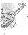
FIGS. 1-4 illustrate various views of an exemplarymiter saw assembly 10 with acircular saw 200 detached from amiter base 100, in accordance with an example embodiment of the present invention.FIGS. 5-6 illustrate views of an exemplary miter sawassembly 10 with acircular saw 200 detachably coupled to amiter base 100, in accordance with an example embodiment of the present invention.- Referring to
FIGS. 1-6 , amiter saw assembly 10 comprises amiter base 100 and a detachablycoupleable circular saw 200. Themiter base 100 comprises asupport arm 102 and abase 120. Thesupport arm 102 may comprise avertical pivot 104, a bevel pivot 106 (if themiter saw assembly 10 is a compound miter saw, for example), ahorizontal pivot 108, and a coupling arm. In various embodiments, such as if themiter saw assembly 10 is a sliding compound miter saw, thesupport arm 102 may comprise sliding rails (not shown) such that thecircular saw 200 can be pushed towards the rear of themiter base 100 and/or pulled towards the front of themiter base 100 while in the cutting position. Thevertical pivot 104 allows acircular saw 200 detachably coupled to the coupling arm to pivot downward to a cutting position and upward from the cutting position. Thebevel pivot 106 allows acircular saw 200 detachably coupled to the coupling arm to tilt sideways to provide beveled cuts, for example. In certain embodiments, thecircular saw 200 can be folded at thebevel pivot 106 to lay on top of themiter base 100 to provide for easier transport of themiter saw assembly 10. Thehorizontal pivot 108 allows acircular saw 200 detachably coupled to the coupling arm to rotate horizontally to provide angled cuts, for example. - The coupling arm is operable to detachably couple with the
circular saw 200. In an example embodiment, the coupling arm may comprise aslide 110, aslide cover 112, alocking mechanism 114, alocking lever 116, and asupport arm lever 126. Theslide 110 extends from thevertical pivot 104 and detachably couples with anattachment mechanism 220 of thecircular saw 200. Thelocking mechanism 114 secures theslide 110 to theattachment mechanism 220 when thecircular saw 200 is coupled to themiter base 100. Thelocking lever 116 is operable to engage thelocking mechanism 114 to theattachment mechanism 220 when in a closed position and release thelocking mechanism 114 from theattachment mechanism 220 so that thecircular saw 200 can be removed from themiter base 100 when in an open position. Theslide cover 112 houses thelocking mechanism 114 and provides a clean finish for the coupling arm. - The
support arm lever 126 may be a lever that comprises agear 127 that is rotated with thevertical pivot 104 to extend thesupport arm lever 126 from the coupling arm and retract thesupport arm lever 126 to the coupling arm. Thesupport arm lever 126 is operable to mate with and move ablade guard lever 212 of thecircular saw 200 to open ablade guard 216 as thecircular saw 200 attached to the coupling arm pivots downward at thevertical pivot 104, and to close theblade guard 216 as the circular saw 200 pivots upward. For example, when not in use, ablade guard 216 can cover ablade 218 of the circular saw 200 to protect users and passersby from contacting theblade 218 of thecircular saw 200. As thecircular saw 200 is pivoted to a cutting position, thesupport arm lever 126 can extend from the coupling arm and mate with theblade guard lever 212 to slide theblade guard lever 212 from a closed position to an open position. Theblade guard 216 retracts to expose theblade 218 as theblade guard lever 212 is moved from the closed position to the open position. As thecircular saw 200 is pivoted upward from the cutting position, theblade guard lever 212 is moved from the open position to the closed position such that theblade guard 216 extends to cover theblade 218. - The
base 120 comprises a blade receiving miter table 118, ahandle 122, and a fence, 124. Thehandle 122 can be grasped to transport themiter saw assembly 10. The blade receiving miter table 118 is operable to receive acutting blade 218 of acircular saw 200 as thecircular saw 200 vertically pivots downward to a cutting position. In various embodiments, such as if the miter sawassembly 10 is a sliding compound miter saw, theblade 218 of thecircular saw 200 can be pushed within the blade receiving miter table 118 towards the rear of themiter base 100 and/or pulled within the blade receiving miter table 118 towards the front of themiter base 100 while in the cutting position. The blade receiving miter table 118 rotates horizontally about thehorizontal pivot 108 in unison with thesupport arm 102 when thecircular saw 200 coupled to the coupling arm is rotated horizontally to change an angle of a cut, for example. - The
fence 124 is operable to provide a precise cutting angle between the plane of theblade 218 and the plane of a workpiece edge when the workpiece is held against thefence 124. The default angle of thefence 124 in relation to theblade 218 of thecircular saw 200 may be ninety degrees, for example. The angle of thefence 124 in relation to theblade 218 can be adjusted by, for example, horizontally rotating thecircular saw 200 coupled to the coupling arm about thehorizontal pivot 108. - The
circular saw 200 may comprise ahandle 202, amotor 204, apower supply 206, afoot 208, adust port 210, ablade guard lever 212, ahousing 214, ablade guard 216, ablade 218, and anattachment mechanism 220. Thehandle 202 is grasped to operate thecircular saw 200 independently when thecircular saw 200 is decoupled from themiter base 100 and to maneuver thecircular saw 200 as guided by thesupport arm 102 when attached to the coupling arm of themiter base 100. Thehandle 202 can include a grip, such as rubber, grooves, or any suitable material or texture. Thehandle 202 may include buttons, triggers, or the like for activating thecircular saw 200. Themotor 204 is powered by apower supply 206 and is operable to rotate theblade 218 when activated. Thepower supply 206 can be an alternating current (AC) power supply (e.g., through a cord from a plug that mates with a wall socket), a direct current (DC) power supply (e.g., a battery), or any suitable power supply. - The
foot 208 is operable to rest on a surface that is being cut. Particularly, thefoot 208 is generally parallel with the surface being cut when thecircular saw 200 is pivoted downward into the cutting position. In various embodiments, thefoot 208 may automatically adjust to remain generally parallel with the surface being cut as the coupling arm is tilted sideways by thebevel pivot 106. Thefoot 208 can be movable to adjust a depth of a cut. Thedust port 210 can extend from thehousing 214 and is operable to discharge dust formed during a sawing operation. A dust bag (not shown) can be attached to thedust port 210 to collect the dust discharged through the dust port. - The
blade guard lever 212 may be a lever that extends through a slot in thehousing 214 and comprises alever gear 213 that moves within thehousing 214 to extend and retract ablade guard 216. For example, when thecircular saw 200 is detached from themiter base 100 for operation as a circular saw, a user can slide theblade guard lever 212 in a first direction to retract theblade guard 216 such that theblade 218 of thecircular saw 200 is exposed so the user can cut a workpiece, for example. Theblade guard lever 212 is moved in the second direction to extend theblade guard 216 to cover theblade 218 when thecircular saw 200 is not in use, for example. As another example, when thecircular saw 200 is attached to themiter base 100 for operation as a miter saw, theblade guard lever 212 may be moved in the first direction by a component of themiter base 100, such as thesupport arm lever 126, to retract theblade guard 216 such that theblade 218 of thecircular saw 200 is exposed. Thesupport arm lever 126 moves theblade guard lever 212 to open theblade guard 216 as thecircular saw 200 attached to the coupling arm pivots downward at thevertical pivot 104 into the cutting position. Theblade guard lever 212 moves in the second direction to extend theblade guard 216 to cover theblade 218 as thecircular saw 200 pivots upward at thevertical pivot 104 from the cutting position. - The
blade guard 216 protects users and passersby from contacting theblade 218 when thecircular saw 200 and/or miter sawassembly 10 is not in use. Theblade guard 216 comprises a shield that is extended to cover theblade 218 and retracted to expose theblade 218. Theblade guard 216 may comprise agear 217, for example, which is rotated by theblade guard lever 212 to extend and retract theblade guard 216. - The
blade 218 is a circular blade that is rotated by themotor 204 to cut a workpiece. In certain embodiments,different blades 218 can be used for cutting different workpiece materials, such as wood, plastic, metal, or any suitable material. Thedifferent blades 218 can comprise teeth of various sizes and configurations based on the application. Theblade 218 may be metal, such as steel, titanium, or any suitable material. Theblade 218 is removable and replaceable with other circular blades. For example, ablade 218 may be removed and replaced if the workpiece material changes or if the blade is worn, among other things. - The
attachment mechanism 220 is operable to detachably couple thecircular saw 200 to themiter base 100. Theattachment mechanism 220 detachably couples to the coupling arm of themiter base 100. Theattachment mechanism 220 can receive theslide 110 that extends from thevertical pivot 104 of themiter base 100. Theslide 110 can be secured within theattachment mechanism 220 by alocking mechanism 114 of themiter base 100, or any suitable locking mechanism on themiter base 100 or thecircular saw 200. FIGS. 7-8 illustrate perspective views of anexemplary attachment mechanism 220 for detachably coupling acircular saw 200 to amiter base 100, in accordance with an example embodiment of the present invention. Referring toFIGS. 7-8 , theattachment mechanism 220 comprises aslot 222 formed in thehousing 214 between slot indent(s) 224, aslot side wall 228, a slotbottom wall 229, a slottop wall 230, and aslot end 231. The slot indent(s) 224 can be attached to or integrated with theslot bottom wall 229 and/or slottop wall 230. Theslot 222 is operable to receive aslide 110 that fits snugly within theslot 222 to detachably couple thecircular saw 200 to themiter base 100. The slot indent(s) 224 can comprise anindent gap 226 operable to mate with thelocking mechanism 114 to secure theslide 110 within theslot 222. In various embodiments, theslot 222 and slide 110 can be square or rectangular shaped. Alternatively, as illustrated inFIGS. 9-10 and discussed below, for example, theslide 110 and/or slot 222 may be trapezoidal shaped.- The
attachment mechanism 220 illustrated inFIGS. 7-8 shares various characteristics with theattachment mechanism 220 illustrated inFIGS. 1 and3 as described above. FIG. 9 illustrates a rear side perspective view of anexemplary slide 110 andattachment mechanism 220 with aslide clamp 111 for detachably coupling acircular saw 200 to amiter base 100, in accordance with an example embodiment of the present invention. Referring toFIG. 9 , theattachment mechanism 220 comprises aslot 222 formed in thehousing 214. In addition to theslot bottom wall 220 and slot end 231 illustrated inFIG. 9 , theslot 222 comprises slot indent(s) 224, aslot side wall 228, and a slottop wall 230 as described above with reference toFIGS. 7-8 . Theslot 222 can be trapezoidal shaped and comprise aslide clamp 111 attached to at least one of theslot side wall 228, theslot bottom wall 229, or the slot top wall 230 (as illustrated inFIG. 9 ). Theslide clamp 111 can be extended into theslot 222 by a tightening mechanism such as screws (not shown) that extend through thehousing 214 to push theslide clamp 111. Theslide 110 may be trapezoidal shaped such that theslide 110 snugly fits within theslot 222 with theslide clamp 111. In operation, theslide 110 is inserted into theslot 222 to attach thecircular saw 200 to themiter base 100 and the tightening mechanism is tightened extending theslide clamp 111 to squeeze theslide 110 against at least twosurfaces 224, 228-231 of theslot 222. For example, as illustrated inFIG. 9 , tightening theslide clamp 111 exerts a pressure on theslide 110 against theslot side wall 228 and slot bottom wall 229 (i.e., datum surfaces). The tightening mechanism provides a consistent angle between theblade 218 and themiter base 100 each time thecircular saw 200 is attached to themiter base 100 to form a miter saw.- The
slide 110 andattachment mechanism 220 illustrated inFIG. 9 shares various characteristics with theslide 110 andattachment mechanism 220 illustrated in one or more ofFIGS. 1-4 and7-8 as described above. FIG. 10 illustrates a side perspective view of anexemplary slide 110 and anattachment mechanism 220 for detachably coupling acircular saw 200 to amiter base 100, in accordance with an example embodiment of the present invention. Referring toFIG. 10 , theattachment mechanism 220 comprises aslot 222 formed in thehousing 214. Although not specifically illustrated inFIG. 10 , theslot 222 comprises slot indent(s) 224 as described above with reference toFIGS. 7-8 . Theslot 222 can be trapezoidal shaped and may comprise a tightening mechanism such as screws (not shown) that extend through thehousing 214 into the slot when tightened. Theslide 110 may be trapezoidal shaped such that theslide 110 snugly fits within theslot 222. In operation, theslide 110 is inserted into theslot 222 to attach thecircular saw 200 to themiter base 100 and the tightening mechanism is tightened to squeeze theslide 110 against at least twosurfaces 224, 228-231 of theslot 222. For example, as illustrated inFIG. 10 , tightening the tightening mechanism exerts a pressure on theslide 110 against theslot side wall 228 and slot bottom wall 229 (i.e., datum surfaces). The tightening mechanism provides a consistent angle between theblade 218 and themiter base 100 each time thecircular saw 200 is attached to themiter base 100 to form a miter saw.- The
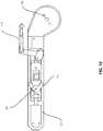
slide 110 andattachment mechanism 220 illustrated inFIG. 10 shares various characteristics with theslide 110 andattachment mechanism 220 illustrated in one or more ofFIGS. 1-4 and7-9 as described above. FIG. 11 illustrates a side perspective view of anexemplary attachment mechanism 220 and anexemplary slide 110 including anexemplary locking mechanism 114 for securing a detachably coupleablecircular saw 200 to amiter base 100, in accordance with an example embodiment of the present invention.FIG. 12 illustrates a side view of anexemplary locking mechanism 114 in a locked position, in accordance with an example embodiment of the present invention.FIG. 13 illustrates a side view of anexemplary locking mechanism 114 in a release position, in accordance with an example embodiment of the present invention.- Referring to
FIGS. 11-13 , theattachment mechanism 220 comprises aslot 222 formed in thehousing 214 between slot indent(s) 224, aslot side wall 228, a slotbottom wall 229, a slottop wall 230, and aslot end 231. The slot indent(s) 224 can be attached to or integrated with theslot bottom wall 229 and/or slottop wall 230. Theslot 222 is operable to receive aslide 110 that fits snugly within theslot 222 to detachably couple thecircular saw 200 to themiter base 100. The slot indent(s) 224 can comprise anindent gap 226 operable to mate with thelocking mechanism 114 to secure theslide 110 within theslot 222. - The
slide 110 extends from thevertical pivot 104 and can detachably couple with anattachment mechanism 220 of thecircular saw 200. Thelocking mechanism 114 is attached to theslide 110 and secures theslide 110 to theattachment mechanism 220 when thecircular saw 200 is coupled to themiter base 100. The lockinglever 116 is operable to engage thelocking mechanism 114 with theattachment mechanism 220 when in a closed position and release thelocking mechanism 114 from theattachment mechanism 220 so that thecircular saw 200 can be removed from themiter base 100 when in an open position. Particularly, thelocking mechanism 114 may comprise lockingprotrusions 115 operable to extend when the lockinglever 116 is moved to a closed position and retract when the lockinglever 116 is moved to an open position. The lockingprotrusions 115 can snap into the indent gap(s) 226 in the slot indent(s) 224 to secure thecircular saw 200 to themiter base 100 when theslide 110 is inserted into theslot 222 and the lockinglever 116 is closed. The lockingprotrusions 115 retract from the indent gap(s) 226 in the slot indent(s) 224 to unlock thecircular saw 200 from themiter base 100 when the lockinglever 116 is opened. FIG. 14 illustrates a side view of an exemplaryblade guard mechanism circular saw housing 214 removed, in accordance with an example embodiment of the present invention.FIG. 15 illustrates a side perspective view of an exemplaryblade guard lever 212 of an exemplaryblade guard mechanism circular saw housing 214 removed, in accordance with an example embodiment of the present invention. Referring toFIGS. 14-15 , the blade guard mechanism comprises asupport arm lever 126 and ablade guard lever 212.- The
blade guard lever 212 is operable to extend and retract ablade guard 216. In an example embodiment, theblade guard lever 212 comprises alever gear 213 that drives ablade guard gear 217 to extend theblade guard 216 to cover theblade 218 and retract theblade guard 216 to expose theblade 218. For example, theblade guard lever 212 may be moved in a first direction to an open position to retract theblade guard 216 such that theblade 218 of thecircular saw 200 is exposed. Theblade guard lever 212 is moved in the second direction to a closed position to extend theblade guard 216 to cover theblade 218. Theblade guard lever 212 can be moved, for example, by a user when operated as acircular saw 200 or by thesupport arm lever 126 when operated as a miter saw. - The
support arm lever 126 is operable to rotate at agear 127 to extend and retract thesupport arm lever 126. Thegear 127 is operable to rotate thesupport arm lever 126 based on rotation at thevertical pivot 104. For example, thesupport arm lever 126 is rotated to extend from the coupling arm when the coupling arm is rotated downward at thevertical pivot 104. Thesupport arm lever 126 is rotated to retract to the coupling arm when the coupling arm is rotated upward at thevertical pivot 104. - The
support arm lever 126 is operable to mate with and move ablade guard lever 212 of thecircular saw 200 to open ablade guard 216 as thecircular saw 200 attached to the coupling arm pivots downward at thevertical pivot 104, and to close theblade guard 216 as thecircular saw 200 pivots upward. For example, ablade guard 216 can cover ablade 218 of thecircular saw 200 when not in use to protect users and passersby from contacting theblade 218 of thecircular saw 200. Thesupport arm lever 126 can extend from the coupling arm and mate with theblade guard lever 212 to slide theblade guard lever 212 from a closed position to an open position as thecircular saw 200 is pivoted to a cutting position. - The
blade guard mechanism FIGS. 14-15 shares various characteristics with theblade guard mechanism FIGS. 1-2 as described above. - According to the present invention, the miter saw
assembly 10 comprises acircular saw 200 and amiter base 100. Thecircular saw 200 comprises acircular blade 218, amotor 204, apower supply 206, and anattachment mechanism 220. Themotor 204 is operable to rotate thecircular blade 218. Thepower supply 206 is operable to provide power to themotor 204. Theattachment mechanism 220 is detachably coupled with a coupling arm. Themiter base 100 comprises abase 120 and asupport arm 102. Thesupport arm 102 comprises the coupling arm, avertical pivot 104, and ahorizontal pivot 108. The coupling arm is detachably coupled with theattachment mechanism 220. Thevertical pivot 104 is operable to pivot the coupling arm in a vertical plane. The horizontal pivot is rotatably coupled with thebase 120. Thehorizontal pivot 108 is operable to rotate the coupling arm in a horizontal plane. - In an example embodiment, the
circular saw 200 comprises ablade guard 216 movable between an extended position covering thecircular blade 218 and a retracted position exposing thecircular blade 218. In various embodiments, thecircular saw 200 comprises ablade guard lever 212 operable to move theblade guard 216 between the extended position and the retracted position. Theblade guard lever 212 is movable between a closed position corresponding to the extended position of theblade guard 216 and an open position corresponding to the retracted position of theblade guard 216. In certain embodiments, theblade guard lever 212 comprises alever gear 213 and theblade guard 216 comprises ablade guard gear 217. Thelever gear 213 is movable with theblade guard lever 212 to drive theblade guard gear 217 to move theblade guard 216 between the extended position and the retracted position. - In various embodiments, the
support arm 102 comprises asupport arm lever 126 rotatably coupled to thesupport arm 102. Thesupport arm lever 126 is operable to rotate between an inward position and an outward position. Thesupport arm lever 126 is operable to move theblade guard lever 212 between the closed position and the open position as thesupport arm lever 126 rotates between the inward position and the outward position. In certain embodiments, thesupport arm lever 126 rotates from the inward position to the outward position as the coupling arm is pivoted downward at thevertical pivot 104. Thesupport arm lever 126 rotates from the outward position to the inward position as the coupling arm is pivoted upward at thevertical pivot 104. In an example embodiment, thesupport arm lever 126 comprises agear 127 that is rotated in unison with thevertical pivot 104 to rotate thesupport arm lever 126 between the inward position and the outward position. - According to the invention, the
attachment mechanism 220 comprises aslot 222 formed in ahousing 214 of thecircular saw 200 between at least oneslot indent 224, aslot side wall 228, a slotbottom wall 229, and a slottop wall 230. The coupling arm comprises aslide 110. Theslide 110 is received within theslot 222 to detachably couple the coupling arm with theattachment mechanism 220. In an example embodiment, theslot 222 and theslide 110 are generally rectangular or square shaped. In various embodiments, theslot 222 and theslide 110 are generally trapezoidal shaped. - In an example embodiment, the
attachment mechanism 220 comprises a tightening mechanism operable to apply pressure to theslide 110 such that theslide 110 is pushed against at least two of the at least oneslot indent 224, theslot side wall 228, theslot bottom wall 229, and the slottop wall 230. In various embodiments, theslot 222 comprises aslide clamp 111 attached to at least one of theslot side wall 228, theslot bottom wall 229, and the slottop wall 230. The tightening mechanism is operable to apply pressure to theslide 110 by forcing theslide clamp 111 against theslide 110. In certain embodiments, the tightening mechanism is at least one screw that is extendable through thehousing 214 into theslot 222. - In various embodiments, the coupling arm comprises a
locking mechanism 114 operable to secure theslide 110 within theslot 222. In certain embodiments, theslot indent 224 comprises anindent gap 226. Thelocking mechanism 114 comprises aprotrusion 115 operable to extend into theindent gap 226 to secure theslide 110 within theslot 222, and retract from theindent gap 226 to release theslide 110 such that theslide 110 is removable from theslot 222. In an example embodiment, the coupling arm comprises a lockinglever 116 operable to move between a locked position and an unlocked position. The lockinglever 116 is operable to extend theprotrusion 115 when moved to the locked position and retract theprotrusion 115 when moved to the unlocked position. - In certain embodiments, the
support arm 102 comprises abevel pivot 106 operable to tilt the coupling arm sideways. In an example embodiment, thebevel pivot 106 is operable to fold thecircular saw 200 to lay on top of thebase 120. In various embodiments, thecircular saw 200 comprises afoot 208 operable to rest on a surface of a workpiece being cut by thecircular blade 218. Thefoot 208 is movable to adjust a depth of a cut. Thefoot 208 automatically adjusts to remain generally parallel with the surface of the workpiece as the coupling arm is tilted sideways at thebevel pivot 106. In certain embodiments, thesupport arm 102 comprises sliding rails. Thecircular saw 200 detachably coupled to themiter base 100 is pushed towards a rear of themiter base 100 and pulled towards a front of themiter base 100 on the sliding rails. - Although devices and systems according to the present invention may have been described in connection with a preferred embodiment, it is not intended to be limited to the specific form set forth herein, but on the contrary, it is intended to cover such alternative, modifications, and equivalents, as can be reasonably included within the scope of the invention as defined by the appended claims.
- While the present invention has been described with reference to certain embodiments, it will be understood by those skilled in the art that various changes may be made and equivalents may be substituted without departing from the scope of the present invention. In addition, many modifications may be made to adapt a particular situation or material to the teachings of the present invention without departing from its scope. Therefore, it is intended that the present invention not be limited to the particular embodiment disclosed, but that the present invention will include all embodiments falling within the scope of the appended claims.
Claims (9)
- A miter saw assembly (10) comprising:a circular saw (200) comprising:a circular blade (218),a motor (204) operable to rotate the circular blade (218),a power supply (206) operable to provide power to the motor (204), andan attachment mechanism (220); anda miter base (100) comprising:a base (120), anda support arm (102) comprising:a coupling arm detachably coupled with the attachment mechanism (220) of the circular saw (200),a vertical pivot (104) operable to pivot the coupling arm in a vertical plane, anda horizontal pivot (108) rotatably coupled with the base (120), the horizontal pivot (108) operable to rotate the coupling arm in a horizontal plane,characterized in that:the attachment mechanism (220) comprises a slot (222) formed in a housing (214) of the circular saw (200) between at least one slot indent (224), a slot side wall (228), a slot bottom wall (229), and a slot top wall (230),the coupling arm comprises a slide (110), andthe slide (110) is received within the slot (222) to detachably couple the coupling arm with the attachment mechanism (220).
- The miter saw assembly according to claim 1, wherein the slot (222) and the slide (110) are generally rectangular or square shaped.
- The miter saw assembly according to claim 1, wherein the slot (222) and the slide (110) are generally trapezoidal shaped.
- The miter saw assembly according to claim 1, wherein the attachment mechanism (220) comprises a tightening mechanism operable to apply pressure to the slide (110) such that the slide (110) is pushed against at least two of the at least one slot indent (224), the slot side wall (228), the slot bottom wall (229), and the slot top wall (230).
- The miter saw assembly according to claim 4, wherein the slot (222) comprises a slide clamp (111) attached to at least one of the slot side wall (228), the slot bottom wall (229), and the slot top wall (230), and wherein the tightening mechanism is operable to apply pressure to the slide (110) by forcing the slide clamp (111) against the slide (110).
- The miter saw assembly according to claim 4, wherein the tightening mechanism is at least one screw that is extendable through the housing (214) into the slot (222).
- The miter saw assembly according to claim 1, wherein the coupling arm comprises a locking mechanism (114) operable to secure the slide (110) within the slot (222).
- The miter saw assembly according to claim 7, wherein the slot indent (224) comprises an indent gap (226), and wherein the locking mechanism (114) comprises a protrusion (115) operable to:extend into the indent gap (226) to secure the slide (110) within the slot (222), andretract from the indent gap (226) to release the slide (110) such that the slide (110) is removable from the slot (222).
- The miter saw assembly according to claim 8, wherein the coupling arm comprises a locking lever (116) operable to move between a locked position and an unlocked position, the locking lever (116) operable to extend the protrusion (115) when moved to the locked position and retract the protrusion (115) when moved to the unlocked position.
Priority Applications (2)
| Application Number | Priority Date | Filing Date | Title |
|---|---|---|---|
| EP16172686.4AEP3088113B1 (en) | 2014-03-03 | 2015-02-26 | Miter saw assembly with detachable circular saw |
| EP16172700.3AEP3088114A1 (en) | 2014-03-03 | 2015-02-26 | Miter saw assembly with detachable circular saw |
Applications Claiming Priority (1)
| Application Number | Priority Date | Filing Date | Title |
|---|---|---|---|
| US14/195,224US9463515B2 (en) | 2014-03-03 | 2014-03-03 | Miter saw assembly with detachable circular saw |
Related Child Applications (4)
| Application Number | Title | Priority Date | Filing Date |
|---|---|---|---|
| EP16172700.3ADivisionEP3088114A1 (en) | 2014-03-03 | 2015-02-26 | Miter saw assembly with detachable circular saw |
| EP16172700.3ADivision-IntoEP3088114A1 (en) | 2014-03-03 | 2015-02-26 | Miter saw assembly with detachable circular saw |
| EP16172686.4ADivision-IntoEP3088113B1 (en) | 2014-03-03 | 2015-02-26 | Miter saw assembly with detachable circular saw |
| EP16172686.4ADivisionEP3088113B1 (en) | 2014-03-03 | 2015-02-26 | Miter saw assembly with detachable circular saw |
Publications (3)
| Publication Number | Publication Date |
|---|---|
| EP2915617A2 EP2915617A2 (en) | 2015-09-09 |
| EP2915617A3 EP2915617A3 (en) | 2015-11-25 |
| EP2915617B1true EP2915617B1 (en) | 2020-10-21 |
Family
ID=52596381
Family Applications (3)
| Application Number | Title | Priority Date | Filing Date |
|---|---|---|---|
| EP16172686.4ANot-in-forceEP3088113B1 (en) | 2014-03-03 | 2015-02-26 | Miter saw assembly with detachable circular saw |
| EP15156791.4ANot-in-forceEP2915617B1 (en) | 2014-03-03 | 2015-02-26 | Miter saw assembly with detachable circular saw |
| EP16172700.3AWithdrawnEP3088114A1 (en) | 2014-03-03 | 2015-02-26 | Miter saw assembly with detachable circular saw |
Family Applications Before (1)
| Application Number | Title | Priority Date | Filing Date |
|---|---|---|---|
| EP16172686.4ANot-in-forceEP3088113B1 (en) | 2014-03-03 | 2015-02-26 | Miter saw assembly with detachable circular saw |
Family Applications After (1)
| Application Number | Title | Priority Date | Filing Date |
|---|---|---|---|
| EP16172700.3AWithdrawnEP3088114A1 (en) | 2014-03-03 | 2015-02-26 | Miter saw assembly with detachable circular saw |
Country Status (2)
| Country | Link |
|---|---|
| US (2) | US9463515B2 (en) |
| EP (3) | EP3088113B1 (en) |
Families Citing this family (9)
| Publication number | Priority date | Publication date | Assignee | Title |
|---|---|---|---|---|
| US9962852B2 (en)* | 2014-08-29 | 2018-05-08 | Black & Decker Inc. | Miter saw with improved carrying mode |
| US10780510B2 (en)* | 2014-09-10 | 2020-09-22 | Rexon Industrial Corp., Ltd. | Foldable miter saws and foldable method of miter saw |
| TWI535512B (en)* | 2014-09-12 | 2016-06-01 | 力山工業股份有限公司 | Foldable miter saw and folding method of foldable miter saw |
| US10654188B2 (en)* | 2014-12-31 | 2020-05-19 | Robert Bosch Tool Corporation | Guide foot for an oscillating cutting tool |
| US9810524B2 (en) | 2015-12-15 | 2017-11-07 | Sears Brands, L.L.C. | Power tool with optical measurement device |
| US10906110B2 (en) | 2017-04-28 | 2021-02-02 | Transform Sr Brands Llc | Power tool with integrated measurement device and associated methods |
| CN109382551B (en)* | 2017-08-14 | 2020-08-14 | 苏州宝时得电动工具有限公司 | Power tool |
| JP7321754B2 (en)* | 2018-09-07 | 2023-08-07 | 株式会社マキタ | portable cutting machine |
| US12023824B1 (en)* | 2023-05-26 | 2024-07-02 | Jayantha Sarath Mallikarachchi | Triple saw |
Family Cites Families (8)
| Publication number | Priority date | Publication date | Assignee | Title |
|---|---|---|---|---|
| GB966065A (en) | 1962-04-25 | 1964-08-06 | Wolf Electric Tools Ltd | Improvements relating to portable electric saws |
| US3680609A (en)* | 1970-12-28 | 1972-08-01 | Troy Steel Corp | Cutting apparatus |
| US4587875A (en) | 1985-05-02 | 1986-05-13 | Theodore Deley | Portable sawing device utilizing a circular power saw |
| US4648301A (en)* | 1985-05-20 | 1987-03-10 | L Investments, Ltd. | Adapter for circular saw to cut-off saw |
| US9027450B1 (en)* | 2003-01-21 | 2015-05-12 | Roland Santa Ana | Work piece cutting apparatus |
| TWI327511B (en) | 2007-01-25 | 2010-07-21 | Rexon Ind Corp Ltd | Power device |
| US8919235B2 (en) | 2009-03-17 | 2014-12-30 | Hitachi Koki Co., Ltd. | Cutting apparatus |
| WO2013055625A2 (en) | 2011-10-15 | 2013-04-18 | RBWL Licensing Holdings, LLC | Multifunctional saw apparatus and method |
- 2014
- 2014-03-03USUS14/195,224patent/US9463515B2/ennot_activeExpired - Fee Related
- 2015
- 2015-02-26EPEP16172686.4Apatent/EP3088113B1/ennot_activeNot-in-force
- 2015-02-26EPEP15156791.4Apatent/EP2915617B1/ennot_activeNot-in-force
- 2015-02-26EPEP16172700.3Apatent/EP3088114A1/ennot_activeWithdrawn
- 2016
- 2016-09-09USUS15/260,635patent/US10010955B2/enactiveActive
Non-Patent Citations (1)
| Title |
|---|
| None* |
Also Published As
| Publication number | Publication date |
|---|---|
| US10010955B2 (en) | 2018-07-03 |
| EP3088114A1 (en) | 2016-11-02 |
| US9463515B2 (en) | 2016-10-11 |
| EP2915617A2 (en) | 2015-09-09 |
| US20150246399A1 (en) | 2015-09-03 |
| EP3088113A1 (en) | 2016-11-02 |
| EP2915617A3 (en) | 2015-11-25 |
| US20160375511A1 (en) | 2016-12-29 |
| EP3088113B1 (en) | 2018-08-22 |
Similar Documents
| Publication | Publication Date | Title |
|---|---|---|
| EP2915617B1 (en) | Miter saw assembly with detachable circular saw | |
| CA2751464C (en) | Hand saw | |
| CN107511935B (en) | Assembly for cutting and collecting dust or slurry | |
| US9713849B2 (en) | Multifunctional saw apparatus and method | |
| US20090149120A1 (en) | Combination Of Knife Block And Knife Sharpener With Guard | |
| US20050086812A1 (en) | Utility knife with dual retractable cutting guides | |
| US6321454B1 (en) | Utility knife | |
| CA2974671C (en) | Miter saw | |
| WO2007095130A2 (en) | Double-edged utility knife | |
| GB2495205A (en) | Saw assembly with pivot hinge dust port | |
| EP2753446B1 (en) | Miter saw with double belt drive | |
| CN217394891U (en) | Modular workstation | |
| US9808961B2 (en) | Electric dust free saw | |
| US20180071942A1 (en) | Multifunctional saw apparatus and method | |
| US7509900B2 (en) | Scroll saw with dust collector | |
| US20140259693A1 (en) | Safety Cutter | |
| WO2005099975A2 (en) | Utility knife for glaziers | |
| CN104520079B (en) | handheld planer | |
| US20200361111A1 (en) | Combination miter and table saw | |
| JP4347021B2 (en) | Dust case mounting structure for cutting tools | |
| CN218457976U (en) | Planing and wiping device | |
| KR101797662B1 (en) | A knife Grinding Machine | |
| US20130333176A1 (en) | Device and associated crack repair system | |
| CA2519665C (en) | Utility knife with dual retractable cutting guides | |
| CA2275128C (en) | Utility knife |
Legal Events
| Date | Code | Title | Description |
|---|---|---|---|
| PUAI | Public reference made under article 153(3) epc to a published international application that has entered the european phase | Free format text:ORIGINAL CODE: 0009012 | |
| AK | Designated contracting states | Kind code of ref document:A2 Designated state(s):AL AT BE BG CH CY CZ DE DK EE ES FI FR GB GR HR HU IE IS IT LI LT LU LV MC MK MT NL NO PL PT RO RS SE SI SK SM TR | |
| AX | Request for extension of the european patent | Extension state:BA ME | |
| PUAL | Search report despatched | Free format text:ORIGINAL CODE: 0009013 | |
| AK | Designated contracting states | Kind code of ref document:A3 Designated state(s):AL AT BE BG CH CY CZ DE DK EE ES FI FR GB GR HR HU IE IS IT LI LT LU LV MC MK MT NL NO PL PT RO RS SE SI SK SM TR | |
| AX | Request for extension of the european patent | Extension state:BA ME | |
| RIC1 | Information provided on ipc code assigned before grant | Ipc:B23D 47/02 20060101ALI20151022BHEP Ipc:B23D 59/00 20060101AFI20151022BHEP | |
| 17P | Request for examination filed | Effective date:20160517 | |
| RBV | Designated contracting states (corrected) | Designated state(s):AL AT BE BG CH CY CZ DE DK EE ES FI FR GB GR HR HU IE IS IT LI LT LU LV MC MK MT NL NO PL PT RO RS SE SI SK SM TR | |
| GRAP | Despatch of communication of intention to grant a patent | Free format text:ORIGINAL CODE: EPIDOSNIGR1 | |
| STAA | Information on the status of an ep patent application or granted ep patent | Free format text:STATUS: GRANT OF PATENT IS INTENDED | |
| RIC1 | Information provided on ipc code assigned before grant | Ipc:B23D 47/02 20060101ALI20200403BHEP Ipc:B23D 59/00 20060101AFI20200403BHEP Ipc:B27G 19/04 20060101ALN20200403BHEP Ipc:B23D 45/04 20060101ALI20200403BHEP | |
| RIC1 | Information provided on ipc code assigned before grant | Ipc:B23D 47/02 20060101ALI20200414BHEP Ipc:B23D 45/04 20060101ALI20200414BHEP Ipc:B27G 19/04 20060101ALN20200414BHEP Ipc:B23D 59/00 20060101AFI20200414BHEP | |
| INTG | Intention to grant announced | Effective date:20200430 | |
| RAP1 | Party data changed (applicant data changed or rights of an application transferred) | Owner name:TRANSFORM SR BRANDS LLC | |
| GRAS | Grant fee paid | Free format text:ORIGINAL CODE: EPIDOSNIGR3 | |
| GRAA | (expected) grant | Free format text:ORIGINAL CODE: 0009210 | |
| STAA | Information on the status of an ep patent application or granted ep patent | Free format text:STATUS: THE PATENT HAS BEEN GRANTED | |
| AK | Designated contracting states | Kind code of ref document:B1 Designated state(s):AL AT BE BG CH CY CZ DE DK EE ES FI FR GB GR HR HU IE IS IT LI LT LU LV MC MK MT NL NO PL PT RO RS SE SI SK SM TR | |
| REG | Reference to a national code | Ref country code:GB Ref legal event code:FG4D | |
| REG | Reference to a national code | Ref country code:CH Ref legal event code:EP | |
| REG | Reference to a national code | Ref country code:IE Ref legal event code:FG4D | |
| REG | Reference to a national code | Ref country code:DE Ref legal event code:R096 Ref document number:602015060678 Country of ref document:DE | |
| REG | Reference to a national code | Ref country code:AT Ref legal event code:REF Ref document number:1325332 Country of ref document:AT Kind code of ref document:T Effective date:20201115 | |
| REG | Reference to a national code | Ref country code:AT Ref legal event code:MK05 Ref document number:1325332 Country of ref document:AT Kind code of ref document:T Effective date:20201021 | |
| REG | Reference to a national code | Ref country code:NL Ref legal event code:MP Effective date:20201021 | |
| PG25 | Lapsed in a contracting state [announced via postgrant information from national office to epo] | Ref country code:GR Free format text:LAPSE BECAUSE OF FAILURE TO SUBMIT A TRANSLATION OF THE DESCRIPTION OR TO PAY THE FEE WITHIN THE PRESCRIBED TIME-LIMIT Effective date:20210122 Ref country code:FI Free format text:LAPSE BECAUSE OF FAILURE TO SUBMIT A TRANSLATION OF THE DESCRIPTION OR TO PAY THE FEE WITHIN THE PRESCRIBED TIME-LIMIT Effective date:20201021 Ref country code:RS Free format text:LAPSE BECAUSE OF FAILURE TO SUBMIT A TRANSLATION OF THE DESCRIPTION OR TO PAY THE FEE WITHIN THE PRESCRIBED TIME-LIMIT Effective date:20201021 Ref country code:PT Free format text:LAPSE BECAUSE OF FAILURE TO SUBMIT A TRANSLATION OF THE DESCRIPTION OR TO PAY THE FEE WITHIN THE PRESCRIBED TIME-LIMIT Effective date:20210222 Ref country code:NO Free format text:LAPSE BECAUSE OF FAILURE TO SUBMIT A TRANSLATION OF THE DESCRIPTION OR TO PAY THE FEE WITHIN THE PRESCRIBED TIME-LIMIT Effective date:20210121 Ref country code:NL Free format text:LAPSE BECAUSE OF FAILURE TO SUBMIT A TRANSLATION OF THE DESCRIPTION OR TO PAY THE FEE WITHIN THE PRESCRIBED TIME-LIMIT Effective date:20201021 | |
| REG | Reference to a national code | Ref country code:LT Ref legal event code:MG4D | |
| PG25 | Lapsed in a contracting state [announced via postgrant information from national office to epo] | Ref country code:AT Free format text:LAPSE BECAUSE OF FAILURE TO SUBMIT A TRANSLATION OF THE DESCRIPTION OR TO PAY THE FEE WITHIN THE PRESCRIBED TIME-LIMIT Effective date:20201021 Ref country code:ES Free format text:LAPSE BECAUSE OF FAILURE TO SUBMIT A TRANSLATION OF THE DESCRIPTION OR TO PAY THE FEE WITHIN THE PRESCRIBED TIME-LIMIT Effective date:20201021 Ref country code:BG Free format text:LAPSE BECAUSE OF FAILURE TO SUBMIT A TRANSLATION OF THE DESCRIPTION OR TO PAY THE FEE WITHIN THE PRESCRIBED TIME-LIMIT Effective date:20210121 Ref country code:SE Free format text:LAPSE BECAUSE OF FAILURE TO SUBMIT A TRANSLATION OF THE DESCRIPTION OR TO PAY THE FEE WITHIN THE PRESCRIBED TIME-LIMIT Effective date:20201021 Ref country code:IS Free format text:LAPSE BECAUSE OF FAILURE TO SUBMIT A TRANSLATION OF THE DESCRIPTION OR TO PAY THE FEE WITHIN THE PRESCRIBED TIME-LIMIT Effective date:20210221 Ref country code:PL Free format text:LAPSE BECAUSE OF FAILURE TO SUBMIT A TRANSLATION OF THE DESCRIPTION OR TO PAY THE FEE WITHIN THE PRESCRIBED TIME-LIMIT Effective date:20201021 Ref country code:LV Free format text:LAPSE BECAUSE OF FAILURE TO SUBMIT A TRANSLATION OF THE DESCRIPTION OR TO PAY THE FEE WITHIN THE PRESCRIBED TIME-LIMIT Effective date:20201021 | |
| PG25 | Lapsed in a contracting state [announced via postgrant information from national office to epo] | Ref country code:HR Free format text:LAPSE BECAUSE OF FAILURE TO SUBMIT A TRANSLATION OF THE DESCRIPTION OR TO PAY THE FEE WITHIN THE PRESCRIBED TIME-LIMIT Effective date:20201021 | |
| REG | Reference to a national code | Ref country code:DE Ref legal event code:R097 Ref document number:602015060678 Country of ref document:DE | |
| PG25 | Lapsed in a contracting state [announced via postgrant information from national office to epo] | Ref country code:RO Free format text:LAPSE BECAUSE OF FAILURE TO SUBMIT A TRANSLATION OF THE DESCRIPTION OR TO PAY THE FEE WITHIN THE PRESCRIBED TIME-LIMIT Effective date:20201021 Ref country code:SK Free format text:LAPSE BECAUSE OF FAILURE TO SUBMIT A TRANSLATION OF THE DESCRIPTION OR TO PAY THE FEE WITHIN THE PRESCRIBED TIME-LIMIT Effective date:20201021 Ref country code:LT Free format text:LAPSE BECAUSE OF FAILURE TO SUBMIT A TRANSLATION OF THE DESCRIPTION OR TO PAY THE FEE WITHIN THE PRESCRIBED TIME-LIMIT Effective date:20201021 Ref country code:EE Free format text:LAPSE BECAUSE OF FAILURE TO SUBMIT A TRANSLATION OF THE DESCRIPTION OR TO PAY THE FEE WITHIN THE PRESCRIBED TIME-LIMIT Effective date:20201021 Ref country code:CZ Free format text:LAPSE BECAUSE OF FAILURE TO SUBMIT A TRANSLATION OF THE DESCRIPTION OR TO PAY THE FEE WITHIN THE PRESCRIBED TIME-LIMIT Effective date:20201021 Ref country code:SM Free format text:LAPSE BECAUSE OF FAILURE TO SUBMIT A TRANSLATION OF THE DESCRIPTION OR TO PAY THE FEE WITHIN THE PRESCRIBED TIME-LIMIT Effective date:20201021 | |
| PLBE | No opposition filed within time limit | Free format text:ORIGINAL CODE: 0009261 | |
| STAA | Information on the status of an ep patent application or granted ep patent | Free format text:STATUS: NO OPPOSITION FILED WITHIN TIME LIMIT | |
| PG25 | Lapsed in a contracting state [announced via postgrant information from national office to epo] | Ref country code:DK Free format text:LAPSE BECAUSE OF FAILURE TO SUBMIT A TRANSLATION OF THE DESCRIPTION OR TO PAY THE FEE WITHIN THE PRESCRIBED TIME-LIMIT Effective date:20201021 | |
| REG | Reference to a national code | Ref country code:DE Ref legal event code:R119 Ref document number:602015060678 Country of ref document:DE | |
| 26N | No opposition filed | Effective date:20210722 | |
| PG25 | Lapsed in a contracting state [announced via postgrant information from national office to epo] | Ref country code:MC Free format text:LAPSE BECAUSE OF FAILURE TO SUBMIT A TRANSLATION OF THE DESCRIPTION OR TO PAY THE FEE WITHIN THE PRESCRIBED TIME-LIMIT Effective date:20201021 | |
| GBPC | Gb: european patent ceased through non-payment of renewal fee | Effective date:20210226 | |
| REG | Reference to a national code | Ref country code:BE Ref legal event code:MM Effective date:20210228 | |
| PG25 | Lapsed in a contracting state [announced via postgrant information from national office to epo] | Ref country code:IT Free format text:LAPSE BECAUSE OF FAILURE TO SUBMIT A TRANSLATION OF THE DESCRIPTION OR TO PAY THE FEE WITHIN THE PRESCRIBED TIME-LIMIT Effective date:20201021 Ref country code:LU Free format text:LAPSE BECAUSE OF NON-PAYMENT OF DUE FEES Effective date:20210226 Ref country code:LI Free format text:LAPSE BECAUSE OF NON-PAYMENT OF DUE FEES Effective date:20210228 Ref country code:AL Free format text:LAPSE BECAUSE OF FAILURE TO SUBMIT A TRANSLATION OF THE DESCRIPTION OR TO PAY THE FEE WITHIN THE PRESCRIBED TIME-LIMIT Effective date:20201021 Ref country code:CH Free format text:LAPSE BECAUSE OF NON-PAYMENT OF DUE FEES Effective date:20210228 | |
| PG25 | Lapsed in a contracting state [announced via postgrant information from national office to epo] | Ref country code:SI Free format text:LAPSE BECAUSE OF FAILURE TO SUBMIT A TRANSLATION OF THE DESCRIPTION OR TO PAY THE FEE WITHIN THE PRESCRIBED TIME-LIMIT Effective date:20201021 | |
| PG25 | Lapsed in a contracting state [announced via postgrant information from national office to epo] | Ref country code:FR Free format text:LAPSE BECAUSE OF NON-PAYMENT OF DUE FEES Effective date:20210228 Ref country code:GB Free format text:LAPSE BECAUSE OF NON-PAYMENT OF DUE FEES Effective date:20210226 Ref country code:IE Free format text:LAPSE BECAUSE OF NON-PAYMENT OF DUE FEES Effective date:20210226 Ref country code:DE Free format text:LAPSE BECAUSE OF NON-PAYMENT OF DUE FEES Effective date:20210901 | |
| PG25 | Lapsed in a contracting state [announced via postgrant information from national office to epo] | Ref country code:IS Free format text:LAPSE BECAUSE OF FAILURE TO SUBMIT A TRANSLATION OF THE DESCRIPTION OR TO PAY THE FEE WITHIN THE PRESCRIBED TIME-LIMIT Effective date:20210221 | |
| PG25 | Lapsed in a contracting state [announced via postgrant information from national office to epo] | Ref country code:BE Free format text:LAPSE BECAUSE OF NON-PAYMENT OF DUE FEES Effective date:20210228 | |
| PG25 | Lapsed in a contracting state [announced via postgrant information from national office to epo] | Ref country code:HU Free format text:LAPSE BECAUSE OF FAILURE TO SUBMIT A TRANSLATION OF THE DESCRIPTION OR TO PAY THE FEE WITHIN THE PRESCRIBED TIME-LIMIT; INVALID AB INITIO Effective date:20150226 | |
| PG25 | Lapsed in a contracting state [announced via postgrant information from national office to epo] | Ref country code:CY Free format text:LAPSE BECAUSE OF FAILURE TO SUBMIT A TRANSLATION OF THE DESCRIPTION OR TO PAY THE FEE WITHIN THE PRESCRIBED TIME-LIMIT Effective date:20201021 | |
| PG25 | Lapsed in a contracting state [announced via postgrant information from national office to epo] | Ref country code:MK Free format text:LAPSE BECAUSE OF FAILURE TO SUBMIT A TRANSLATION OF THE DESCRIPTION OR TO PAY THE FEE WITHIN THE PRESCRIBED TIME-LIMIT Effective date:20201021 | |
| PG25 | Lapsed in a contracting state [announced via postgrant information from national office to epo] | Ref country code:TR Free format text:LAPSE BECAUSE OF FAILURE TO SUBMIT A TRANSLATION OF THE DESCRIPTION OR TO PAY THE FEE WITHIN THE PRESCRIBED TIME-LIMIT Effective date:20201021 | |
| PG25 | Lapsed in a contracting state [announced via postgrant information from national office to epo] | Ref country code:MT Free format text:LAPSE BECAUSE OF FAILURE TO SUBMIT A TRANSLATION OF THE DESCRIPTION OR TO PAY THE FEE WITHIN THE PRESCRIBED TIME-LIMIT Effective date:20201021 |