EP2911593B1 - Percutaneous tissue anchor techniques - Google Patents
Percutaneous tissue anchor techniquesDownload PDFInfo
- Publication number
- EP2911593B1 EP2911593B1EP13849843.1AEP13849843AEP2911593B1EP 2911593 B1EP2911593 B1EP 2911593B1EP 13849843 AEP13849843 AEP 13849843AEP 2911593 B1EP2911593 B1EP 2911593B1
- Authority
- EP
- European Patent Office
- Prior art keywords
- anchor
- tool
- tissue
- eyelet
- typically
- Prior art date
- Legal status (The legal status is an assumption and is not a legal conclusion. Google has not performed a legal analysis and makes no representation as to the accuracy of the status listed.)
- Active
Links
Images


Classifications
- A—HUMAN NECESSITIES
- A61—MEDICAL OR VETERINARY SCIENCE; HYGIENE
- A61B—DIAGNOSIS; SURGERY; IDENTIFICATION
- A61B17/00—Surgical instruments, devices or methods
- A61B17/12—Surgical instruments, devices or methods for ligaturing or otherwise compressing tubular parts of the body, e.g. blood vessels or umbilical cord
- A61B17/12009—Implements for ligaturing other than by clamps or clips, e.g. using a loop with a slip knot
- A—HUMAN NECESSITIES
- A61—MEDICAL OR VETERINARY SCIENCE; HYGIENE
- A61B—DIAGNOSIS; SURGERY; IDENTIFICATION
- A61B17/00—Surgical instruments, devices or methods
- A61B17/04—Surgical instruments, devices or methods for suturing wounds; Holders or packages for needles or suture materials
- A61B17/0401—Suture anchors, buttons or pledgets, i.e. means for attaching sutures to bone, cartilage or soft tissue; Instruments for applying or removing suture anchors
- A—HUMAN NECESSITIES
- A61—MEDICAL OR VETERINARY SCIENCE; HYGIENE
- A61B—DIAGNOSIS; SURGERY; IDENTIFICATION
- A61B17/00—Surgical instruments, devices or methods
- A61B2017/00477—Coupling
- A—HUMAN NECESSITIES
- A61—MEDICAL OR VETERINARY SCIENCE; HYGIENE
- A61B—DIAGNOSIS; SURGERY; IDENTIFICATION
- A61B17/00—Surgical instruments, devices or methods
- A61B2017/00681—Aspects not otherwise provided for
- A—HUMAN NECESSITIES
- A61—MEDICAL OR VETERINARY SCIENCE; HYGIENE
- A61B—DIAGNOSIS; SURGERY; IDENTIFICATION
- A61B17/00—Surgical instruments, devices or methods
- A61B17/04—Surgical instruments, devices or methods for suturing wounds; Holders or packages for needles or suture materials
- A61B17/0401—Suture anchors, buttons or pledgets, i.e. means for attaching sutures to bone, cartilage or soft tissue; Instruments for applying or removing suture anchors
- A61B2017/0409—Instruments for applying suture anchors
- A—HUMAN NECESSITIES
- A61—MEDICAL OR VETERINARY SCIENCE; HYGIENE
- A61B—DIAGNOSIS; SURGERY; IDENTIFICATION
- A61B17/00—Surgical instruments, devices or methods
- A61B17/04—Surgical instruments, devices or methods for suturing wounds; Holders or packages for needles or suture materials
- A61B17/0401—Suture anchors, buttons or pledgets, i.e. means for attaching sutures to bone, cartilage or soft tissue; Instruments for applying or removing suture anchors
- A61B2017/0411—Instruments for removing suture anchors
- A—HUMAN NECESSITIES
- A61—MEDICAL OR VETERINARY SCIENCE; HYGIENE
- A61B—DIAGNOSIS; SURGERY; IDENTIFICATION
- A61B17/00—Surgical instruments, devices or methods
- A61B17/04—Surgical instruments, devices or methods for suturing wounds; Holders or packages for needles or suture materials
- A61B17/0401—Suture anchors, buttons or pledgets, i.e. means for attaching sutures to bone, cartilage or soft tissue; Instruments for applying or removing suture anchors
- A61B2017/044—Suture anchors, buttons or pledgets, i.e. means for attaching sutures to bone, cartilage or soft tissue; Instruments for applying or removing suture anchors with a threaded shaft, e.g. screws
- A61B2017/0441—Suture anchors, buttons or pledgets, i.e. means for attaching sutures to bone, cartilage or soft tissue; Instruments for applying or removing suture anchors with a threaded shaft, e.g. screws the shaft being a rigid coil or spiral
- A—HUMAN NECESSITIES
- A61—MEDICAL OR VETERINARY SCIENCE; HYGIENE
- A61B—DIAGNOSIS; SURGERY; IDENTIFICATION
- A61B17/00—Surgical instruments, devices or methods
- A61B17/04—Surgical instruments, devices or methods for suturing wounds; Holders or packages for needles or suture materials
- A61B17/0401—Suture anchors, buttons or pledgets, i.e. means for attaching sutures to bone, cartilage or soft tissue; Instruments for applying or removing suture anchors
- A61B2017/0464—Suture anchors, buttons or pledgets, i.e. means for attaching sutures to bone, cartilage or soft tissue; Instruments for applying or removing suture anchors for soft tissue
- A—HUMAN NECESSITIES
- A61—MEDICAL OR VETERINARY SCIENCE; HYGIENE
- A61B—DIAGNOSIS; SURGERY; IDENTIFICATION
- A61B17/00—Surgical instruments, devices or methods
- A61B17/04—Surgical instruments, devices or methods for suturing wounds; Holders or packages for needles or suture materials
- A61B2017/0496—Surgical instruments, devices or methods for suturing wounds; Holders or packages for needles or suture materials for tensioning sutures
- A—HUMAN NECESSITIES
- A61—MEDICAL OR VETERINARY SCIENCE; HYGIENE
- A61B—DIAGNOSIS; SURGERY; IDENTIFICATION
- A61B17/00—Surgical instruments, devices or methods
- A61B17/28—Surgical forceps
- A61B17/29—Forceps for use in minimally invasive surgery
- A61B2017/2926—Details of heads or jaws
- A61B2017/2932—Transmission of forces to jaw members
- A61B2017/2933—Transmission of forces to jaw members camming or guiding means
- A61B2017/2937—Transmission of forces to jaw members camming or guiding means with flexible part
- A—HUMAN NECESSITIES
- A61—MEDICAL OR VETERINARY SCIENCE; HYGIENE
- A61F—FILTERS IMPLANTABLE INTO BLOOD VESSELS; PROSTHESES; DEVICES PROVIDING PATENCY TO, OR PREVENTING COLLAPSING OF, TUBULAR STRUCTURES OF THE BODY, e.g. STENTS; ORTHOPAEDIC, NURSING OR CONTRACEPTIVE DEVICES; FOMENTATION; TREATMENT OR PROTECTION OF EYES OR EARS; BANDAGES, DRESSINGS OR ABSORBENT PADS; FIRST-AID KITS
- A61F2/00—Filters implantable into blood vessels; Prostheses, i.e. artificial substitutes or replacements for parts of the body; Appliances for connecting them with the body; Devices providing patency to, or preventing collapsing of, tubular structures of the body, e.g. stents
- A61F2/02—Prostheses implantable into the body
- A61F2/24—Heart valves ; Vascular valves, e.g. venous valves; Heart implants, e.g. passive devices for improving the function of the native valve or the heart muscle; Transmyocardial revascularisation [TMR] devices; Valves implantable in the body
- A61F2/2442—Annuloplasty rings or inserts for correcting the valve shape; Implants for improving the function of a native heart valve
- A61F2/2445—Annuloplasty rings in direct contact with the valve annulus
Definitions
- the present disclosurerelates in general to medical devices. More specifically, the present disclosure relates to tissue anchors and tool for manipulation of tissue anchors, such as for percutaneous use.
- Tissue anchorsare used to facilitate implantation of medical implants, such as by coupling such implants to tissue.
- a tissue anchormay be driven through the implant and into the tissue while the implant is held in place.
- the tissue anchormay be implanted before introduction of the medical implant, and the medical implant subsequently coupled to the tissue anchor.
- US Application 12/608,316 published as US 2011/0106247provides apparatus for use with an implant, the apparatus including a tissue anchor, which comprises a distal tissue coupling element, which is configured to penetrate cardiac tissue, and a proximal implant-penetrating element configured to penetrate the implant.
- the proximal implant-penetrating elementis shaped so as to define a passage therethrough, which passage has at least two openings that are within 1 mm of a proximal end of the implant-penetrating element.
- the apparatusalso comprises a cord configured to be removably passed through the passage.
- Tissue anchor apparatusand techniques for use thereof, are described.
- a toolis described for manipulating tissue anchors.
- the toolmay be configured for retrieval of already-implanted tissue anchors.
- the toolmay be configured to be coupled to a tissue anchor at a non-zero angle with respect to the tissue anchor, and to subsequently be aligned with the tissue anchor.
- the toolmay be configured to be advanced through a sleeve of an implant that has been implanted using tissue anchors, and to de-anchor at least one of the tissue anchors, thereby de-anchoring at least part of the sleeve from the tissue.
- a tissue anchorhaving a helical tissue-coupling element and an engaging head that comprises an eyelet.
- the toolmay be configured to be initially articulatably coupled to the tissue anchor (e.g., to the eyelet), and to be subsequently rigidly-coupled to the tissue anchor.
- the toolmay be configured to couple to the eyelet such that, together, the eyelet and an anchor-engaging element of the tool resemble links in a chain.
- An anchor driveris described for implanting the tissue anchor.
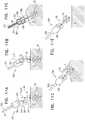
- FIGs. 1A-3Care schematic illustrations of a tissue anchor 40 and a tool 80 for use with the tissue anchor.
- Anchor 40is shown in two rotational views in Figs. 1A-B , respectively.
- Anchor 40comprises a tissue-coupling element 42, and an engaging head comprising a coupling eyelet 46 defined by a bar (e.g., a shaft) 44.
- tissue-coupling element 42comprises a helical tissue-coupling element, configured to be screwed into, and optionally screwed out of, tissue of a subject.
- Eyelet 46provides a coupling interface for tool 80 and/or another tool.
- tool 80is typically configured, and used, to retrieve anchor 40 from tissue of the subject (e.g., after the anchor has been previously implanted and/or used to facilitate implantation of an implant). Tool 80 may also be configured and/or used to implant anchor 40. A different tool may be used to implant anchor 40.
- Anchor 40has a central longitudinal axis a1, from a distal end of tissue-coupling element 42 to a proximal end of eyelet 46.
- a central helix axis of helical tissue-coupling element 42is coaxial with axis a1.
- Eyelet 46typically defines a plane a4 (see also Fig. 6A ), on which the central helix axis and/or axis a1 typically lie.
- a height d1 of eyelet 46is at least 80 percent as great as a width d2 of the eyelet (e.g., approximately equal to width d2, or greater than width d2, such as at least 50 percent greater than width d2).
- bar 44defines an arch portion of eyelet 46
- anchor 40e.g., the engaging head thereof
- anchor 40comprises a base 48 that defines a base portion of the eyelet, and couples the eyelet to tissue-coupling element 42.
- the arch portion of the eyeletis thereby oriented such that a crest 43 of the arch portion is further from tissue-coupling element 42 than is a base 45 of the arch portion.
- the shape (e.g., curvature) of the archis typically such that the arch continues to widen for most, if not all, of its length from crest 43 to base 45.
- any portion of bar 44 that is parallel to longitudinal axis a1has a height along the longitudinal axis that is less than 50 percent (e.g., less than 20 percent, such as less than 10 percent) of height d1 of the eyelet.
- Such portionsmay be considered 'imposts' of the arch portion that are less than 50 percent (e.g., less than 20 percent, such as less than 10 percent) of the overall height of the arch portion.
- the arch portion of the eyeletmay have a generally parabolic shape.
- Bar 44has a thickness (e.g., a bore) d3.
- Figs. 2A-Bshow side and distal-end views, respectively, of a distal portion of tool 80.
- Tool 80comprises a housing 82 that has an inner surface 84 that defines a generally cylindrical compartment 86 that has a transverse width (e.g., a diameter) d4.
- An opening 88 at a distal end 83 of the housingprovides fluid communication between compartment 86 and the outside of the housing.
- Two or more protrusions 90protrude radially inward from inner surface 84 into compartment 86, such that a distance d5 across the compartment between the protrusions is smaller than width d4 of the compartment, and also smaller than width d2 of eyelet 46 of anchor 40.
- Width d4 of compartment 86is typically slightly greater than width d2 of eyelet 46, so as to accommodate the eyelet without allowing enough space for the eyelet to move significantly within the compartment.
- width d4may be at least 5 percent, less than 30 percent, and/or between 5 and 30 percent greater (e.g., 10-20 percent greater) than width d2.
- Tool 80further comprises an anchor-engaging element 91 comprising one or more (e.g., two) arms 92, each arm defining a proximal stem portion 93 and distal portion 94 (e.g., a distal hook portion), and the arms typically curving inwardly toward each other so as to define a space 96 therebetween (e.g., between respective proximal stem portions). That is, the curve of each arm defines a concavity 103, and the concavity of each arm faces the concavity of the other arm, so as to define at least part of space 96.
- stem portion 93may be generally straight. It is to be noted, that even when stem portion 93 is generally straight, arm 92 would typically still define a concavity at a site 104 where portion 93 meets distal portion 94.
- Figs. 2A-B(and Fig. 3A ) show arms in an extended position thereof, in which at least the distal portion of each arm protrudes out of opening 88 and is disposed outside compartment 86, and a gap between the distal portions has a width d6 that is great enough for at least part of bar 44 to move through, into space 96.
- width d6is greater than thickness d3 of bar 44 of eyelet 46 of anchor 40 (e.g., at least 5 times as great as thickness d3, such as at least 10 times as great as thickness d3, such as at least 20 times as great as thickness d3).
- Width d6is further typically greater than width d4 of compartment 86, e.g., at least 1.5 times as great, less than 4 times as great, and/or between 1.5 times and 4 times as great.
- Arms 92(e.g., portion 93 and/or portion 94 thereof) have a thickness d7 that is typically less than 0.5 times as great (e.g., less than 0.2 times as great, such as less than 0.1 times as great) as width d6, and/or less than width d4 (e.g., less than 0.5 times as great as width d4, such as less than 0.2 times as great as width d4).
- a plane a5 on which arms 92 liemay typically be disposed at least 20 degrees, up to 90 degrees, and/or between 20 and 90 degrees with respect to a transverse axis a3 between protrusions 90.
- plane a5may be disposed at about 45 degrees with respect to axis a3. This orientation is discussed hereinbelow with respect to Figs. 6A-E .
- stem portion 93 of each arm 92typically protrudes distally away from housing 82 and outward from a longitudinal axis a2 of tool 80, and distal portion 94 of each arm protrudes from a distal end of the stem portion and inward toward the longitudinal axis. Further typically, distal portion 94 of each arm protrudes from the distal end of stem portion 93 distally away from the housing.
- Distal portion 94(e.g., an inner surface thereof) is disposed at an angle alpha A with respect to longitudinal axis a2, angle alpha_A typically being greater than 40 degrees, less than 85 degrees, and/or between 40 and 85 degrees (e.g., between 50 and 80 degrees, such as between 50 and 70 degrees and/or between 70 and 80 degrees). Due at least in part to these geometries, arms 92 typically do not define effective hooks while in the extended position. It is hypothesized that such a configuration reduces a likelihood of arms 92 inadvertently hooking to tissue or apparatus within the body of the subject.
- Arms 92further have a retracted position in which at least part of distal portion 94 of each arm is typically disposed inside compartment 86, as shown in Fig. 3C .
- arms 92In the retracted position, arms 92 define a loop (e.g., distal portions 94 are in contact with each other), thereby shaping space 96 to define an aperture 97.
- Figs. 3A-Cshow stages in the transition of arms 92 from the extended position ( Fig. 3A ) to the retracted position ( Fig. 3C).
- Fig. 3Bshows an intermediate position of arms 92 that is partway between the extended position and the retracted position, illustrating that as the arms move from the extended position to the retracted position, the arms form the loop before assuming the retracted position (e.g., before arms 92 completely enter compartment 86).
- distal portions 94are at least 10 times further (e.g., at least 20 times further) from each other when in the extended position than when in the retracted position.
- distal portion of one armis in contact with the distal portion of another (e.g., the other) arm.
- Each distal portionmay be shaped to define a beveled edge, so as to facilitate contact (e.g., mating) of the distal portions.
- the angle at which distal portion 94 is disposed with respect to longitudinal axis a2approaches, and typically passes, 90 degrees, such that each arm forms a hook (e.g., as shown in Figs. 3B-C ).
- this angleat least reaches 90 degrees before distal portions 94 contact each other. It is hypothesized that such a configuration facilitates preliminary coupling (e.g., hooking) of a single arm 92 to eyelet 46 before the arms reach the intermediate and/or retracted position. This may be advantageous, for example, when coupling tool 80 to a tissue anchor that is not disposed close to longitudinal axis a2 of tool 80.
- Tool 80further comprises an extracorporeal controller 110, which comprises a handle 112 and an adjuster 114, such as a switch or a lever.
- Adjuster 114is configured to move arms 92 between the extended and retracted states.
- arms 92are typically moved between the extended and retracted states by moving housing 82 distally while the arms remain stationary (e.g., with respect to anchor 40 and/or tissue of the subject).
- Such a configurationfacilitates coupling of arms 92 to eyelet 46 of the anchor with a reduced likelihood of the arms inadvertently moving away from the eyelet.
- typically (1) adjuster 114is coupled to housing 82 and is configured to reversibly move the housing further and closer from handle 112, and (2) handle 112 is coupled to arms 92 such that a distance along tool 80 between the handle and the housing is fixed.
- adjuster 114is moved so as to move arms 92 between the extended position and the retracted position (e.g., via the intermediate position).
- a tactile and/or visual indicatorindicates at least a state of adjuster 114 in which arms 92 are in the intermediate position (as shown in Fig. 3B ).
- controller 110is configured to partially hold adjuster 114 in one or more states, such as in the state in which arms 92 are in the intermediate position.
- FIGs. 4A-E , 5A-B , and 6A-Eare schematic illustrations of a system 100, comprising tissue anchor 40 and tool 80, and of use of the tool to retrieve the anchor from tissue 10 of the subject.
- Fig. 4Ashows anchor 40 having been previously implanted in tissue 10 (e.g., to facilitate implantation of an implant; not shown in Fig. 4A , but a non-limiting illustrative example is described with reference to Figs. 9A-10 ).
- Tool 80is advanced toward anchor 40 with arms 92 in the extended position, such that arms 92 pass around bar 44 of eyelet 46 (i.e., such that the bar passes through the gap between the distal portions of the arms and into the space between the arms).
- Housing 82is moved distally over at least part of arms 92 (e.g., such that the housing presses on a housing-contacting surface 105 of the arms), such that the arms move into the intermediate position, trapping bar 44 within aperture 97 defined by the loop formed by the arms ( Fig. 4B ). That is, aperture 97 acts as or defines an eyelet-retention area.
- arms 92are articulatably coupled to eyelet 46
- the armse.g., the loop defined thereby
- eyelet 46generally resemble links in a chain (e.g., this state is an articulatably-coupled state)
- eyelet 46inhibits movement of tool 80 (e.g., anchor-engaging element 91 thereof) away from tissue anchor 40.
- aperture 97 (1)defines an area that is at least 10 times greater (e.g., at least 20 times greater, such as at least 40 times greater) than that of a transverse cross-sectional area of bar 44 of anchor 40, (2) has a width d8 (see Fig.
- 3Be.g., a smallest width and/or a width transverse to longitudinal axis a2) that is at least 3 times greater (e.g., at least 5 times greater, such as at least 8 times greater) than thickness d3 of bar 44, and/or (3) has a width d8 that is greater (e.g., at least 2 times greater e.g., at least 4 times greater, such as at least 10 times greater) than a depth of the aperture, which is defined by thickness d7 of arms 92.
- aperture 97is typically (1) wider than bar 44 (e.g., at least 3 times wider, e.g., at least 5 times wider, such as at least 8 times wider), and/or (2) wider than itself is deep (e.g., at least 2 times wider, e.g., at least 4 times wider, such as at least 10 times greater).
- These relative dimensions of aperture 97 and bar 44facilitate the articulatable coupling of tool 80 to eyelet 46, and/or coupling of tool 80 to the eyelet at a wide range of possible angles of attack, e.g., as described hereinbelow.
- Tool 80may comprise only one arm, and bar 44 may be trapped by the one arm, e.g., by being hooked by the one arm, and/or by being trapped between the one arm and inner surface 84 of compartment 86.
- Tool 80may comprise two arms, but only one of the arms defines a concavity.
- the other one of the armsmay be straight, and the space between the arms is shaped to define an asymmetric aperture when distal portion 94 of the arm that defines the concavity comes into contact with a distal portion of the straight arm (e.g., as described with reference to Fig. 21 , mutatis mutandis ).
- tool 80is shown having been advanced toward, and coupled to eyelet 46 with a longitudinal axis a2 of the tool (e.g., of housing 82) at a nonzero angle of attack with respect to longitudinal axis a1 of anchor 40.
- Fig. 5Amore clearly shows that tool 80 is configured to engage (e.g., to be coupled to) eyelet 46 at a variety of angles of attack, including deflection in a plane defined by longitudinal axis a1 of the tissue anchor, and around axis a1.
- tool 80may be coupled to eyelet 46 while axis a2 is generally parallel to tissue 10, perpendicular to the tissue, or at any angle of attack therebetween.
- tool 80is configured to engage the coupling eyelet at at least 180 degrees of deflection of longitudinal axis a2 with respect to longitudinal axis a1 (e.g., in a plane on which axis a1 lies).
- tool 80may be coupled to eyelet 46 at at least most (e.g., all) rotational angles of attack around longitudinal axis a1, e.g., at at least 300 degrees of deflection of axis a2 around axis a1.
- tool 80when tool 80 is advanced from a given direction (e.g., due to anatomical and/or other constraints), the tool is couplable to eyelet 46 at at least most (e.g., all) rotational angles of attack of anchor 40 around its longitudinal axis.
- the above possible angles of attack of tool 80may also be translated into three-dimensional terms.
- the possible angles of attack of tool 80typically, together, define a three-dimensional angular span of at least 1 steradian (e.g., at least 3 steradians, such as at least 7 steradians) around eyelet 46.
- a spanis illustrated schematically, by way of example, as span 102 in Fig. 5B .
- tool 80is deflectable into any of the angles described hereinabove as angles of attack.
- tool 80is typically deflectable into any angle that lies within the three-dimensional angular span(s) that are described with reference to Figs. 5A-B , such as span 102 (e.g., a three-dimensional angular span that is at least 1 steradian, such as at least 3 steradians, such as at least 7 steradians).
- tool 80may subsequently be manipulated so as to reduce the angle between axes a1 and a2, e.g., to at least in part align the tool and anchor 40 ( Fig. 4C ).
- tool 80may be rotated, pulled slightly proximally (e.g., along axis a2) and/or moved orthogonally with respect to axis a2.
- tissue 10is sufficiently soft and/or flexible that the tissue responsively deforms (e.g., temporarily), allowing anchor 40 to move into a position in which axes a1 and a2 are more closely aligned.
- arms 92are moved into the retracted position, typically by housing 82 being slid over the arms (e.g., while arms 92 remain stationary), and thereby also over at least part of (e.g., most of, or all of) eyelet 46 ( Fig. 4D ). Housing 82 thereby typically functions as an arm actuator. By moving arms 92 into the retracted position, at least part of eyelet 46 moves into the compartment of housing 82.
- the retracted positionis described hereinabove as having at least part of distal portion 94 of each arm typically disposed inside compartment 86, as shown in Fig. 3C , it is to be noted that for some cases, distal portions do not enter compartment 86.
- distal portions 94may remain just outside of compartment 86, e.g., sufficiently close to the compartment that at least part of eyelet 46 moves into the compartment when the arms move into the retracted position.
- Housing 82is configured to receive eyelet 46 at a plurality of rotational positions (e.g., a continuum of rotational positions) with respect to the housing. Portions of bar 44 of eyelet 46 become disposed in a circumferential space between protrusions 90.
- Fig. 6Awhich is a cross-sectional view of system 100 with eyelet 46 disposed within compartment 86 of housing 82 (as indicated by section "VIA-VIB" in Fig. 4D )
- transverse axis a3 between protrusions 90 of the housingmay be disposed at a continuum of rotational positions with respect to plane a4 defined by eyelet 46.
- this continuum of rotational positionsspans at least 90 degrees (e.g., at least 150 degrees, such as almost 180 degrees) around axis a2.
- Housing 82may be configured to receive eyelet 46 at one or more continua of rotational positions of plane a4, that span a total of at least 270 degrees around longitudinal axis a2.
- Fig. 6Aschematically shows rotational positions in which eyelet 46 may be disposed, by way of "phantom" portions of bar 44.
- housing 82is configured to receive eyelet 46 at a plurality (e.g., a continuum) of rotational positions with respect to the housing
- the orientation of arms 92e.g., plane a5 thereof
- protrusions 90e.g., axis a3 therebetween
- the eyelete.g., plane a4 thereof
- the arrangement of protrusionsmay bias plane a4 toward an angular span 91 that is generally centered orthogonally to axis a5.
- FIG. 6Aschematically shows a rotational position of the eyelet (e.g., into which the eyelet is biased) by way of shaded portions of bar 44, disposed generally central within angular span 91. It is hypothesized that such biasing may inhibit axis a4 from aligning with axis a3 (which might otherwise inhibit entry of eyelet 46 into compartment 86 of housing 82). It is further hypothesized that such biasing may advantageously align protrusions 90 and eyelet 46 in advance of rotation of anchor 40 (which is described hereinbelow with reference to Figs. 4E and 6A-E).
- Fig. 6Bshows, for clarity, the same arrangement of elements as Fig. 6A , but without the "phantom" portions of bar 44, and with less annotation.
- arms 92are articulatably coupled to eyelet 46.
- the compartment of housing 82is typically dimensioned such that the eyelet fits generally snugly therewithin. Thereby movement of eyelet 46 into the compartment of housing 82 typically inhibits articulation of the eyelet with respect to the arms.
- the state of system 100 shown in Fig. 4D (and Fig. 4E )may thereby, for some cases, be a rigidly-coupled state.
- the dimensions and/or shape of eyelet 46e.g., of bar 44 thereof, such as those described with reference to Figs 1A-B , facilitate entry of the eyelet into the compartment of housing 82, such as by facilitating alignment of anchor 40 with tool 80.
- curvature of the arch portion of eyelet 46may facilitate alignment of axes a1 and a2 as the eyelet is moved into the compartment of housing 82.
- housing 82is rotated so as to rotate, and thereby unscrew, anchor 40 from tissue 10.
- rotation of housing 82moves protrusions 90 until they engage (e.g., contact and press against) bar 44 of eyelet 46 ( Figs. 6C-D ).
- Further rotation of housing 82applies a de-anchoring rotational force to eyelet 46, thereby rotating the eyelet and anchor 40 as a whole, and thereby unscrewing the anchor from tissue 10 ( Fig. 6E ).
- a proximal/pulling forceis applied to anchor 40 by a first element of tool 80 (i.e., anchor-engaging element 91, e.g., arms 92 thereof)
- a rotational/torque forceis applied by a second element of the tool (i.e., housing 82, e.g., protrusions 90 thereof). That is, pulling and rotation of anchor 40 are conducted by two distinct elements of tool 80 that are movable (e.g., longitudinally slidable) with respect to each other.
- rotating housing 82 in the reverse directionmay screw anchor 40 into tissue 10.
- Tool 80may be used to re-anchor anchor 40 into tissue 10, or may even be used for the initial anchoring of the anchor.
- tissue-coupling element 42may pierce a portion of an implant and penetrate tissue 10, such that base 48 sandwiches the portion of the implant to the tissue.
- Fig. 7is a schematic illustration of a proximal portion of tool 80, including extracorporeal controller 110, which comprises handle 112 and adjuster 114.
- adjuster 114is coupled to housing 82 and is configured to reversibly move the housing further and closer from handle 112, and (2) handle 112 is coupled to arms 92 such that a distance along tool 80 between the handle and the housing is fixed.
- Adjuster 114may be coupled to a tubular longitudinal member 116 (e.g., via a cam 118), the tubular longitudinal member being slidable with respect to handle 112, and a distal end of the tubular longitudinal member being coupled to housing 82.
- tubular longitudinal member 116may comprise and/or define housing 82.
- handle 112is typically coupled (e.g., fixedly coupled) to a longitudinal member 120 (e.g., via a fastener 122, such as a set screw), a distal end of the longitudinal member being coupled (e.g., fixedly coupled) to arms 92, and tubular longitudinal member 116 is slidable over the longitudinal member.
- longitudinal member 120is disposed through tubular longitudinal member 116.
- handle 112is coupled to a proximal end of longitudinal member 120 that is exposed from a proximal end of tubular longitudinal member 116.
- Tool 80is typically used to retrieve anchor 40 percutaneously (e.g., transluminally). Housing 80, tubular longitudinal member 116 and longitudinal member 120 are thereby configured to be percutaneously advanced to a site at which anchor 40 is implanted. For example, when tool 80 is configured to transluminally retrieve anchor 40, housing 80, tubular longitudinal member 116 and longitudinal member 120 are dimensioned to fit within the blood vessel(s) through which they are to be advanced, and the tubular longitudinal member and the longitudinal member are sufficiently flexible to follow the transluminal route.
- extracorporeal controller 110comprises and/or defines an indicator 124 that indicates a state of adjuster 114, and thereby the position of arms 92.
- Indicator 124may comprise a visual indicator, such as markings, and/or may comprise a tactile indicator, such as graduated ridges 126 with which a part of adjuster 114 interfaces.
- Indicator 124typically indicates at least a state of adjuster 114 in which arms 92 are in the intermediate position in which they define the loop but are not in the retracted position.
- Indicator 124may also indicate one or more states of adjuster 114 in which arms 92 are between the extended position and the intermediate position (e.g., partially closed), e.g., so as to facilitate advancement of tool 80 through a narrow lumen.
- Indicator 124(e.g., ridges 126 thereof) may be configured to partially hold adjuster 114 in one or more states, such as in the state in which arms 92 are in the intermediate position.
- Each arm 92may have a generally sigmoid shape, in which (1) an inwardly convex proximal portion 99 of the arm (e.g., an inwardly convex proximal portion of stem portion 93) curves away from axis a2, and (2) an inwardly concave distal portion 101 of the arm (e.g., distal portion 94, and/or an inwardly convex distal portion of stem portion 93) curves at least in part back toward axis a2, and defines concavity 103 described hereinabove. It is hypothesized that this configuration facilitates at least some of the functionalities described herein. For example:
- Fig. 8is a schematic illustration of arms 92.
- the proximal stem portion 93 of arms 92are coupled to each other (e.g., fixedly coupled to each other, or articulatably coupled to each other).
- a forked member 140comprising a continuous piece of material, may define arms 92 (e.g., each tine of the forked member defining a respective arm). Arms 92 may be biased toward deflecting away from each other, such as by forked member 140 comprising a resilient material.
- the resilient materialmay allow arms 92 to progressively bend and/or deflect toward each other as the arms are progressively moved into compartment 86 of housing 82 (e.g., as the arms progressively move toward the intermediate and/or retracted position thereof).
- Arms 92are typically disposed on a plane a5 (e.g., when in a relaxed and/or unconstrained state). Arms 92 may be more resistant to bending in plane a5 (i.e., in-plane) than away from plane a5 (i.e., off-plane). For some such cases, when forked member 140 defines arms 92 and comprises a resilient material, the material is more flexible off-plane than it is in-plane.
- Fig. 8shows in phantom arms 92 being bent off-plane.
- arms 92facilitates decoupling of arms 92 from an element to which they are coupled (e.g., to which they are inadvertently coupled), such as by moving (e.g., rotating) tool 80 in order to bend and thereby release the arm from the element.
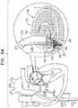
- FIGs. 9A-Care schematic illustrations of a procedure for implanting an annuloplasty ring structure 222 to repair a mitral valve 230.
- Annuloplasty ring structure 222is used to repair a dilated valve annulus of an atrioventricular valve, such as mitral valve 230.
- the annuloplasty ringmay be configured to be placed only partially around the valve annulus (e.g., to assume a C-shape), and, once anchored in place, to be contracted so as to circumferentially tighten the valve annulus.
- the annuloplasty ringcomprises a flexible sleeve 228 and a plurality of anchors 40.
- An anchor deployment manipulator 261comprising an anchor driver 236 and a deployment element 238 at a distal end of the anchor driver, is advanced into a lumen of sleeve 228, and, from within the lumen, deploys the anchors through a wall of the sleeve and into cardiac tissue, thereby anchoring the sleeve around a portion of the valve annulus.
- Annuloplasty ring structure 222may be implanted, mutatis mutandis, using techniques described in US Application 12/437,103, filed May 7, 2009 which published as US 2010/0286767 , and/or US Application 12/689,635, filed January 19, 2010 which published as US 2010/0280604 , both of which are assigned to the assignee of the present application.
- Annuloplasty ring structure 222may be implanted, mutatis mutandis, using techniques described in US Provisional Application 61/717,303 , which is assigned to the assignee of the present application.
- Annuloplasty ring structure 222comprises an adjusting mechanism 246.
- the adjusting mechanismcomprises a rotatable structure, such as a spool, arranged such that rotation of the rotatable structure contracts the implant structure.
- the implantfurther comprises a longitudinal member 286, such as a wire, which is coupled to the adjusting mechanism.
- a rotation tool(not shown) is provided for rotating the rotatable structure. The tool is configured to be guided along (e.g., over, alongside, or through) longitudinal member 286, to engage the rotatable structure, and to rotate the rotatable structure in response to a rotational force applied to the tool.
- the proceduretypically begins by advancing a semi-rigid guidewire into a right atrium 220 of the patient.
- the procedureis typically performed with the aid of imaging, such as fluoroscopy, transesophageal echo, and/or echocardiography.
- the guidewireprovides a guide for the subsequent advancement of an outer steerable catheter 212 therealong and into the right atrium.
- Catheter 212typically comprises a 14-24 F sheath, although the size may be selected as appropriate for a given patient.
- Catheter 212is advanced through vasculature into the right atrium using a suitable point of origin typically determined for a given patient. For example:
- Catheter 212may be advanced through inferior vena cava 223 of the patient (as shown) and into right atrium 220 using a suitable point of origin typically determined for a given patient.
- Catheter 212is advanced distally until the sheath reaches the interatrial septum, and a resilient needle and a dilator (not shown) are advanced through catheter 212 and into the heart.
- a resilient needle and a dilator(not shown) are advanced through catheter 212 and into the heart.
- the dilatoris advanced to the septum, and the needle is pushed from within the dilator and is allowed to puncture the septum to create an opening that facilitates passage of the dilator and subsequently catheter 212 therethrough and into the left atrium.
- the dilatoris passed through the hole in the septum created by the needle.
- the dilatoris shaped to define a hollow shaft for passage along the needle, and the hollow shaft is shaped to define a tapered distal end.
- This tapered distal endis first advanced through the hole created by the needle.
- the holeis enlarged when the gradually increasing diameter of the distal end of the dilator is pushed through the hole in the septum.
- the advancement of catheter 212 through the septum and into the left atriumis followed by the extraction of the dilator and the needle from within catheter 212.
- Fig. 9Ashows the distal portion of catheter 212 disposed within atrium 224, and a second steerable catheter 214, containing annuloplasty ring structure 222 at a distal end thereof, having been advanced through catheter 212 into left atrium 224.
- a distal end portion of catheter 214extends beyond the distal end of catheter 212.
- the distal end portion of catheter 212is steerable in a first plane that is parallel to a plane of the annulus of mitral valve 230.
- the distal end portion of catheter 214is steerable toward the annulus of valve 230 along a plane that is perpendicular with respect to the steering plane of catheter 212 and that is perpendicular with respect to valve 230.
- the juxtaposition of the two steering planes, along with the ability to slide catheter 214 distally and proximally through catheter 212,allows structure 222, and portions thereof, to be placed at any site on the annulus of valve 230.
- a distal end 251 of sleeve 228is positioned against an annulus 240 of mitral valve 230, e.g., in a vicinity of a left fibrous trigone 242.
- distal end 251 of sleeve 228is shown schematically in the cross-sectional view of the heart, although left trigone 242 is in reality not located in the shown cross-sectional plane, but rather out of the page closer to the viewer.
- distal end 251is positioned in a vicinity of a right fibrous trigone 244 of the mitral valve (configuration not shown).
- deployment manipulator 261deploys a first anchor 40a through the wall of sleeve 228.
- the anchoris deployed by penetrating the wall of the sleeve in a direction parallel to a central longitudinal axis of deployment manipulator 261, or anchor driver 236, and/or parallel to central longitudinal axis of the anchor, into cardiac tissue.
- base 48 of anchor 40(shown in Figs. 1A-B ) secures a portion of sleeve 228 by sandwiching the portion of the sleeve against the tissue to which the anchor is anchored.
- a channel 218is provided disposed snugly within sleeve 228, and anchor driver 236 delivers anchors 40 via the channel.
- Channel 218is more rigid than sleeve 228, and is progressively slid out of the sleeve as subsequent anchors 40 are delivered.
- Anchors 40are typically deployed from a distal end of manipulator 261 while the distal end is positioned such that a central longitudinal axis through the distal end of manipulator 61 forms an angle with a surface of the cardiac tissue of between about 20 and 90 degrees, e.g., between 45 and 90 degrees, such as between about 75 and 90 degrees, such as about 90 degrees.
- anchors 40are deployed from the distal end of manipulator 261 into the cardiac tissue in a direction parallel to the central longitudinal axis through the distal end of manipulator 261. Such an angle is typically provided and/or maintained by channel 218 being more rigid than sleeve 228.
- the distal end of channel 218is typically brought close to the surface of the cardiac tissue (and the wall of sleeve 228 that is disposed against the surface of the cardiac tissue), such that little of each anchor 40 is exposed from the channel before penetrating the sleeve and the tissue.
- the distal end of channel 218may be placed (e.g., pushed) against the wall of the sleeve, sandwiching the sleeve against the cardiac tissue.
- This placement of the distal end of channel 218 against the cardiac tissue (via the wall of the sleeve),may stabilize the distal end during deployment and anchoring of each anchor 40, and thereby facilitates anchoring.
- Pushing of the distal end of channel 218 against the cardiac tissue (via the wall of the sleeve)may temporarily deform the cardiac tissue at the site of contact. This deformation may facilitate identification of the site of contact using imaging techniques (e.g., by identifying a deformation in the border between cardiac tissue and blood), and thereby may facilitate correct positioning of the anchor.
- Anchors 32may be deployed from a lateral portion of manipulator 261.
- channel 218is slid proximally out from a distal portion of sleeve 228, typically facilitated by providing a reference pushing force to sleeve 228 using a reference-force tube (not shown).
- the distal end of channel 218is repositioned along annulus 240 to another site selected for deployment of a second anchor 40b, and the anchor is deployed.
- the first anchoris deployed most distally in the sleeve (generally at or within a few millimeters of the distal tip of the sleeve), and each subsequent anchor is deployed more proximally, such that the sleeve is gradually decoupled from channel 218 in a distal direction during the anchoring procedure (i.e., channel 218 is withdrawn from within sleeve 228, so as to make the successive proximal portion sleeve 228 ready for implantation of a subsequent anchor).
- the already-deployed first anchor 40aholds the anchored end of sleeve 228 in place, so that the sleeve is drawn from the site of the first anchor towards the site of the second anchor.
- deployment manipulator 261e.g., deployment element 238 thereof
- deployment manipulator 261is repositioned along the annulus to additional sites, at which respective anchors (e.g., including anchors 40c and 40d) are deployed, until the last anchor is deployed in a vicinity of right fibrous trigone 244 (or left fibrous trigone 242 if the anchoring began at the right trigone).
- the last anchoris not deployed in the vicinity of a trigone, but is instead deployed elsewhere in a vicinity of the mitral valve, such as in a vicinity of the anterior or posterior commissure.
- Guide member 286is typically left behind, and an adjustment tool 287 is subsequently threaded over and advanced along the guide member toward adjusting mechanism 246 and is used to rotate the spool of the adjusting mechanism, in order to tighten structure 222 by adjusting a degree of tension of a contracting member 226 disposed therewithin.
- Figs. 9A-Cshow a guide member 286, coupled to adjusting mechanism 246, and extending proximally through catheter 214 (e.g., into a lateral opening of the catheter, and through a secondary lumen of the catheter).
- rotation tool 287 and deployment element 238are shown in Fig. 9C as being simultaneously present in the heart of the subject.
- deployment element 238may be withdrawn from the body of the subject before tool 287 is introduced.
- Catheter 214may also be removed, leaving guide member 286 disposed through catheter 212, such that adjustment tool 287 is advanceable through catheter 212, and along the guide member to adjusting mechanism 246.
- the rotation tool and guide member 286are removed from the heart.
- a distal portion of guide member 286may be left within the heart of the patient and the proximal end may be accessible outside the body, e.g., using a port.
- adjusting mechanism 40may be accessed at a later stage following initial implantation and adjustment of ring structure 222.
- a re-access wire 288may be provided, coupled to a proximal portion of the implant (e.g., a portion of the implant that is deployed last), such as to a last anchor (as shown in Fig. 9C ), or to the sleeve of the implant. Should it be determined, after implantation (e.g., and after adjustment) of annuloplasty ring structure 222, that one or more anchors 40 requires retrieval, re-access wire 288 facilitates guidance of tool 80 to annuloplasty ring structure 222 and/or into the lumen thereof (described further with reference to Figs. 10A-B , mutatis mutandis ).
- annuloplasty ring structure 222is implanted by right or left thoracotomy, mutatis mutandis.
- FIGs. 10A-Bare schematic illustrations of tool 80 being used to retrieve an anchor 40 from within a lumen 164 of an implant 160.
- FIGs. 10A-Bshow implant 160 comprising an annuloplasty ring structure 161 comprising a sleeve 162 that has been implanted by sequentially delivering a plurality of anchors 40 (e.g., at least anchors 40a, 40b, 40c, and 40d) (1) through lumen 164 defined by the sleeve, (2) through the sleeve wall and (3) into tissue 10.
- anchors 40e.g., at least anchors 40a, 40b, 40c, and 40d
- Anchors 40are typically delivered via a channel 166 that is disposed within sleeve 162 and is slidable progressively out of the sleeve as each anchor is delivered and anchored.
- One or more elements shown in Fig. 10may comprise respective elements of the same name described with reference to Figs. 9A-C .
- annuloplasty ring structure 161may comprise annuloplasty ring structure 222
- sleeve 162may comprise sleeve 2208
- channel 166may comprise channel 218, and tissue 10 may comprise annulus 240.
- tool 80may be advanced through channel 166 so as to access lumen 164, and thereby the anchor (e.g., as shown in Fig. 10A ).
- Sleeve 162typically facilitates this advancing by mechanically guiding (e.g., by partially constraining movement of) tool 80 and/or channel 166.
- tool 80is being operated (e.g., while arms 92 are being moved between the extended and retracted positions), the arms are exposed out from channel 166 such that the channel does not inhibit movement of the arms.
- the armsmay be disposed at least 5 mm, e.g., at least 10 mm, such as at least 50 mm distal to a distal end of channel 166.
- anchor 140dhas been unscrewed from tissue 10 (and sleeve 162)
- tool 80is used to draw the anchor into channel 166 and out of the body of the subject.
- Tool 80may be advanced not via channel 166, and the channel is subsequently advanced over the tool.
- Tool 80may be guided to annuloplasty ring structure 161 and/or into lumen 164 thereof by being advanced along a re-access wire 288 (shown for structure 222 in Fig. 9C , mutatis mutandis ).
- Re-access wire 288is coupled to a proximal portion of the implant (e.g., a portion of the implant that is deployed last), such as to a last anchor (as shown in Fig. 9C ), or to the sleeve of the implant.
- tool 80may be coupled to that anchor by being advanced past more recently-deployed anchors.
- tool 80may be advanced past anchors 40d and 40c, and coupled to anchor 40b.
- channel 166is not advanced past the more recently-deployed anchors, but rather remains proximal to the most recently-deployed anchor.
- Lumen 164 of sleeve 162has a transverse cross-sectional width (e.g., diameter) d9.
- tool 80is dimensioned to pass, within the lumen, past the more recently-deployed anchors. Further typically, the flexibility of sleeve 162 facilitates such passage, e.g., by deforming in response to the presence of tool 80.
- tubular longitudinal member 116may facilitate advancement of tool 80 through lumen 164, e.g., past bends in sleeve 162.
- tool 80may be advanced distally, and be at least in part guided and/or passively steered by sleeve 162 (e.g., tubular longitudinal member 116 may bend to conform with the direction of the sleeve).
- Such steeringmay be supplemented by rotation of tool 80.
- the gap between distal portions 94 of each armis typically at least 20 percent as great (e.g., at least 50 percent as great, such as at least 80 percent as great) as width d9.
- Such relative dimensionstypically facilitate engagement of eyelet 46 by the arms, e.g., by increasing the likelihood of the eyelet becoming disposed between the arms.
- the features of arms 92(1) not defining effective hooks while in the extended position (described with reference to Fig. 2A ) and/or (2) being more flexible off-plane than in-plane (described with reference to Fig.
- tool 80may also be configured and/or used to implant anchor 40.
- Tool 80may comprise and/or may be analogous to deployment manipulator 261 and/or anchor driver 236 described with reference to Figs. 9A-C (and arms 92 may comprise and/or may be analogous to deployment element 238), mutatis mutandis.
- Imaging techniquessuch as fluoroscopy and/or ultrasound may be used to facilitate the use of tool 80.
- the position of arms 92 (including the rotational position) with respect to eyelet 46may be observed using such imaging techniques, and adjusted accordingly.
- Fluoroscopymay be used, following movement of arms 92 into the intermediate position, to identify successful coupling (e.g., articulatable coupling) of the arms to eyelet 46, such as by identifying the links-in-a-chain arrangement described hereinabove.
- imagingmay be used to confirm that another element, such as sleeve 162, has not been engaged by tool 80. Following identification of the links-in-a-chain arrangement, the operating physician may then move the arms into the retracted position.
- Radiopaque markingsmay be provided on arms 92, eyelet 46, and/or other components of the apparatus.
- some elements of the apparatusmay comprise tantalum, gold, platinum, or another radiopaque material.
- Mechanical guidancesuch as that provided by sleeve 162 (as described hereinabove) may be used to facilitate advancing of tool 80 (e.g., a distal end thereof) to the vicinity of the anchor, and imaging is used (e.g., only) to facilitate fine manipulation of the tool in order to couple the tool to the anchor.
- Height d1 of eyelet 46may be greater than 1.5 mm and/or less than 7 mm, e.g., greater than 2 mm and/or less than 5 mm, such as greater than 2.3 mm and/or less than 2.6 mm (e.g., between 2.3 mm and 2.6 mm).
- Width d2 of eyelet 46may be greater than 1.5 mm and/or less than 4 mm, e.g., greater than 2 mm and/or less than 3 mm, such as greater than 2.3 mm and/or less than 2.5 mm (e.g., between 2.3 mm and 2.5 mm).
- Thickness d3 of bar 44may be greater than 0.15 mm and/or less than 1.5 mm, e.g., greater than 0.2 mm and/or less than 1 mm, such as greater than 0.25 mm and/or less than 0.4 mm (e.g., between 0.25 mm and 0.4 mm).
- Transverse width d4 of compartment 86may be greater than 1.2 mm and/or less than 3.5 mm, e.g., greater than 1.5 mm and/or less than 2.6 mm, such as greater than 2 mm and/or less than 2.4 mm (e.g., between 2 mm and 2.4 mm).
- Distance d5 between protrusions 90may be greater than 0.8 mm and/or less than 3 mm, e.g., greater than 1 mm and/or less than 2.2 mm, such as greater than 1.5 mm and/or less than 2 mm (e.g., between 1.5 mm and 2 mm).
- Width d6 of the gap between distal portions 94 of arms 92may be greater than 2 mm and/or less than 9 mm, e.g., greater than 3 mm and/or less than 8 mm, such as greater than 5 mm and/or less than 7 mm (e.g., between 5 mm and 7 mm).
- Thickness d7 of arms 92may be greater than 0.15 mm and/or less than 1.2 mm, e.g., greater than 0.2 mm and/or less than 0.8 mm, such as greater than 0.3 mm and/or less than 0.5 mm (e.g., between 0.3 mm and 0.5 mm).
- Width d8 of the area defined by aperture 97may be greater than 1 mm and/or less than 3.5 mm, e.g., greater than 1.5 mm and/or less than 2.6 mm, such as greater than 2 mm and/or less than 2.4 mm (e.g., between 2 mm and 2.4 mm).
- Width d9 of lumen 164 of sleeve 162may be greater than 1.8 mm and/or less than 9 mm, e.g., greater than 2.1 mm and/or less than 6 mm, such as greater than 2.5 mm and/or less than 4 mm (e.g., between 2.5 mm and 4 mm).
- Figs. 11A-Eare schematic illustrations of a tool 380 and techniques for use with a tissue anchor such as tissue anchor 40.
- tool 380is also typically configured, and used, to retrieve anchor 40 from tissue of the subject (e.g., after the anchor has been previously implanted and/or used to facilitate implantation of an implant).
- tool 80may alternatively or additionally be configured and/or used to implant anchor 40.
- Tool 380comprises a housing 382 that has an inner surface 384 that defines a generally cylindrical compartment 386 that has a transverse width (e.g., a diameter), as shown in Fig. 2B as width d4 of compartment 86, mutatis mutandis.
- An opening 388 at a distal end 383 of the housingprovides fluid communication between compartment 386 and the outside of the housing.
- One or more protrusions 390may protrude radially inward from inner surface 384 into compartment 386. A distance across the compartment between the protrusions (as shown in Fig.
- width d5 of compartment 86is smaller than the transverse width of the compartment, and also smaller than width d2 of eyelet 46 of anchor 40.
- the transverse width of compartment 386is typically slightly greater than width d2 of eyelet 46, so as to accommodate the eyelet without allowing enough space for the eyelet to move significantly within the compartment.
- the transverse widthmay be at least 5 percent, less than 30 percent, and/or between 5 and 30 percent greater (e.g., 10-20 percent greater) than width d2.
- Housing 382is typically similar to, and may be identical to, housing 82, described hereinabove with reference to Figs. 1A-10 .
- Tool 380further comprises an anchor-engaging element 391 comprising at least one curved arm 392.
- arm 392is shaped to define a distal hook portion 394 which may be helical.
- Arm 392is rotatable, independently of housing 382, around a longitudinal axis a6 of the housing (or of tool 380) by rotating a longitudinal member 383 that extends from the arm out of the body of the subject.
- Arm 392is also slidable, independently of housing 382, along axis a6 such that the arm (e.g., hook portion 394 thereof) is slidable into and out of the housing.
- Fig. 11Ashows arm 392 in an extended position thereof, in which at least hook portion 394 thereof protrudes out of opening 388 and is disposed outside compartment 386. Arm 392 further has a retracted position in which at least part of hook portion 394 is typically disposed inside compartment 386, as shown in Fig. 11C .
- Tool 380further comprises an extracorporeal controller (not shown), which comprises a handle and an adjuster, such as a switch or a lever, coupled to housing 382 via a tubular longitudinal member 393.
- the controller of tool 380may be similar to, or may comprise, controller 110 described hereinabove with reference to tool 80.
- the adjusteris configured to move arm 392 between the extended and retracted states.
- arm 392is typically moved between the extended and retracted states by using tubular longitudinal member 393 to move housing 382 while the arm remains stationary (e.g., with respect to anchor 40 and/or tissue of the subject).
- Such a configurationfacilitates coupling of arm 392 to eyelet 46 of the anchor with a reduced likelihood of the arm inadvertently moving away from the eyelet.
- Fig. 11Ashows anchor 40 having been previously implanted in tissue 10 (e.g., to facilitate implantation of an implant; not shown in Fig. 11A , but a non-limiting illustrative example is described with reference to Figs. 9A-10 ).
- Tool 380is advanced toward anchor 40 with arm 392 in the extended position (or the arm is moved into the extended position after advancing the tool toward the anchor).
- Arm 392is rotated around axis a6, typically while housing 382 does not rotate.
- Hook portion 394hooks through eyelet 46 of anchor 40, preliminarily coupling tool 380 to the anchor ( Fig. 11B ).
- tool 380may be articulatably coupled to eyelet 46 (e.g., this state may be an articulatably-coupled state), e.g., as described hereinabove for tool 80, mutatis mutandis. It is to be noted that in this state, eyelet 46 inhibits movement of tool 380 (e.g., anchor-engaging element 391 thereof) proximally away from tissue anchor 40.
- Tool 380may be configured to detect resistance to rotation of arm 392, and in response thereto, to provide an indication of this resistance, and/or to stop rotation of the arm.
- resistanceis due to successful hooking of eyelet 46, and the indication and/or stopping of rotation may indicate to the operator to continue with the subsequent steps of the procedure.
- resistancemay be due to engagement of an undesirable structure, such as tissue of the subject or part of an implant, in which case the indication and/or stopping of rotation may indicate to the operator to reverse the rotation and/or to reposition arm 392.
- tool 380is shown having been advanced toward, and coupled to eyelet 46 with a longitudinal axis a6 of the tool (e.g., of housing 82) at a nonzero angle of attack with respect to longitudinal axis a1 of anchor 40.
- Tool 380is configured to engage (e.g., to be coupled to) eyelet 46 at a variety of angles of attack, including deflection in a plane defined by longitudinal axis a1 of the tissue anchor, and around axis a1, e.g., as described for tool 80 with reference to Figs. 5A-B , mutatis mutandis.
- tool 380may be coupled to eyelet 46 while axis a6 is generally parallel to tissue 10, perpendicular to the tissue, or at any angle of attack therebetween. That is, tool 380 is configured to engage the coupling eyelet at at least 180 degrees of deflection of longitudinal axis a6 with respect to longitudinal axis a1 (e.g., in a plane on which axis a1 lies). Similarly, tool 380 may be coupled to eyelet 46 at at least most (e.g., all) rotational angles of attack around longitudinal axis a1, e.g., at at least 300 degrees of deflection of axis a6 around axis a1.
- tool 380when tool 380 is advanced from a given direction (e.g., due to anatomical and/or other constraints), the tool is couplable to eyelet 46 at at least most (e.g., all) rotational angles of attack of anchor 40 around its longitudinal axis.
- the above possible angles of attack of tool 380may also be translated into three-dimensional terms.
- the possible angles of attack of tool 380typically, together, define a three-dimensional angular span of at least 1 steradian (e.g., at least 3 steradians, such as at least 7 steradians) around eyelet 46.
- tool 380While tool 380 is articulatably coupled to anchor 40, the tool is deflectable with respect to the anchor. Typically, in this state, tool 380 is deflectable into any of the angles described hereinabove as angles of attack.
- tool 380may subsequently be manipulated so as to reduce the angle between axes a1 and a6, e.g., to at least in part align the tool and anchor 40 (e.g., as described for tool 80 with reference to Fig. 4C , mutatis mutandis ).
- tool 380may be rotated, pulled slightly proximally (e.g., along axis a6) and/or moved orthogonally with respect to axis a6.
- tissue 10is sufficiently soft and/or flexible that the tissue responsively deforms (e.g., temporarily), allowing anchor 40 to move into a position in which axes a1 and a6 are more closely aligned.
- arm 392is moved into the retracted position, typically by housing 382 being slid over the arm (e.g., while the arm remains stationary), and thereby also over at least part of (e.g., most of, or all of) eyelet 46 ( Fig. 11C ).
- at least part of eyelet 46moves into compartment 386.
- Housing 382is configured to receive eyelet 46 at a plurality of rotational positions (e.g., a continuum of rotational positions) with respect to the housing, such that portions of bar 44 of eyelet 46 become disposed in a circumferential space between protrusions 390, e.g., as described hereinabove for housing 82, mutatis mutandis.
- a plurality of rotational positionse.g., a continuum of rotational positions
- Compartment 386is typically dimensioned such that the eyelet fits generally snugly therewithin. Thereby, movement of eyelet 46 into compartment 386 typically inhibits articulation of the eyelet with respect to the arm.
- the state of tool 380 and anchor 40 shown in Fig. 11C (and Figs. 11D-E )may thereby be a rigidly-coupled state.
- the dimensions and/or shape of eyelet 46e.g., of bar 44 thereof, such as those described with reference to Figs 1A-B , facilitate entry of the eyelet into the compartment 386, such as by facilitating alignment of anchor 40 with tool 380.
- curvature of the arch portion of eyelet 46may facilitate alignment of axes a1 and a6 as the eyelet is moved into the compartment.
- housing 382is rotated so as to rotate, and thereby unscrew, anchor 40 from tissue 10.
- rotation of housing 382moves protrusions 390 until they engage (e.g., contact and press against) bar 44 of eyelet 46 (e.g., as described for tool 80 with reference to Figs. 6C-D , mutatis mutandis ).
- Further rotation of housing 382applies a de-anchoring rotational force to eyelet 46, thereby rotating the eyelet and anchor 40 as a whole, and thereby unscrewing the anchor from tissue 10 (e.g., as described for tool 80 with reference to Fig. 6E , mutatis mutandis ).
- rotating housing 382 in the reverse directionmay screw anchor 40 into tissue 10.
- Tool 380may be used to re-anchor anchor 40 into tissue 10, or may even be used for the initial anchoring of the anchor.
- Figs. 11A-Eshow anchor 40 anchored alone to tissue 10
- anchor 40is typically used to anchor another element, such as an implant, to the tissue.
- tissue-coupling element 42may pierce a portion of an implant and penetrate tissue 10, such that base 48 sandwiches the portion of the implant to the tissue.
- tool 380may be used to retrieve an anchor 40 from within a lumen of an implant, as described with reference to Fig. 10 , mutatis mutandis.
- Tool 480is also typically configured, and used, to retrieve anchor 40 from tissue of the subject (e.g., after the anchor has been previously implanted and/or used to facilitate implantation of an implant).
- Tool 480comprises an anchor-engaging element 491 comprising at least one curved arm 492, typically coupled at a proximal end thereof to a mount 492.
- arm 492is generally helical, and is shaped to define a distal hook portion 494. Portion 494 may be simply the distal-most portion of the helix of arm 492.
- Distal hook portion 494may have a smaller helix pitch than more proximal portions of the helix of arm 492.
- the pitchmay be close to zero, such that distal hook portion 494 is disposed generally orthogonal to axis a7 of tool 480, e.g., defining a planar arc.
- Fig. 12Ashows anchor 40 having been previously implanted in tissue 10 (e.g., to facilitate implantation of an implant; not shown in Fig. 12A , but a non-limiting illustrative example is described with reference to Figs. 9A-10 ).
- Tool 480is advanced toward anchor 40, and anchor-engaging element 491 (e.g., arm 492) is rotated around a longitudinal axis a7 of the tool (e.g., by rotating a longitudinal member 483 that extends out of the body of the subject).
- Hook portion 494hooks through eyelet 46 of anchor 40, preliminarily coupling tool 480 to the anchor ( Fig. 12B ).
- arm 492may be articulatably coupled to eyelet 46 such (e.g., this state may be an articulatably-coupled state) such as described hereinabove for tool 80 and/or tool 380, mutatis mutandis. It is to be noted that in this state, eyelet 46 inhibits movement of tool 480 (e.g., anchor-engaging element 491 thereof) proximally away from tissue anchor 40.
- tool 480e.g., anchor-engaging element 491 thereof
- tool 480is shown having been advanced toward, and coupled to eyelet 46 with longitudinal axis a7 of the tool at a nonzero angle of attack with respect to longitudinal axis a1 of anchor 40.
- Tool 480is configured to engage (e.g., to be coupled to) eyelet 46 at a variety of angles of attack, including deflection in a plane defined by longitudinal axis a1 of the tissue anchor, and around axis a1, e.g., as described for tool 80 with reference to Figs. 5A-B , mutatis mutandis.
- tool 480may be coupled to eyelet 46 while axis a7 is generally parallel to tissue 10, perpendicular to the tissue, or at any angle of attack therebetween. That is, tool 480 is configured to engage the coupling eyelet at at least 180 degrees of deflection of longitudinal axis a7 with respect to longitudinal axis a1 (e.g., in a plane on which axis a1 lies). Similarly, tool 480 may be coupled to eyelet 46 at at least most (e.g., all) rotational angles of attack around longitudinal axis a1, e.g., at at least 300 degrees of deflection of axis a7 around axis a1.
- tool 480when tool 480 is advanced from a given direction (e.g., due to anatomical and/or other constraints), the tool is couplable to eyelet 46 at at least most (e.g., all) rotational angles of attack of anchor 40 around its longitudinal axis.
- the above possible angles of attack of tool 480may also be translated into three-dimensional terms.
- the possible angles of attack of tool 480typically, together, define a three-dimensional angular span of at least 1 steradian (e.g., at least 3 steradians, such as at least 7 steradians) around eyelet 46.
- tool 480While tool 480 is articulatably coupled to anchor 40, the tool is deflectable with respect to the anchor. Typically, in this state, tool 480 is deflectable into any of the angles described hereinabove as angles of attack.
- anchor 40provides resistance to further rotation of the tool.
- hook portion 494may abut base 48 of anchor 40, and/or crest 43 of eyelet 46 of the anchor may abut a mount 482 to which anchor-engaging element 491 is coupled.
- Tool 480e.g., the extracorporeal controller thereof
- Tool 480may be configured to detect resistance to rotation of anchor-engaging element 491 (e.g., arm 492), and in response thereto, to provide an indication of this resistance, and/or to stop rotation of the arm (e.g., to provide the physician with an opportunity to decide whether to continue rotating the anchor-engaging element).
- anchor-engaging element 491e.g., arm 492
- a de-anchoring rotational forceto eyelet 46, thereby rotating the eyelet and anchor 40 as a whole, and thereby unscrewing the anchor from tissue 10 ( Figs. 12D-E ).
- the helix defined by tool 480has an opposite handedness to the helix defined by tissue-coupling element 42 of anchor 40. This allows continued rotation of anchor-engaging element 491 in one direction to (1) couple tool 480 to anchor 40, and (2) unscrew the anchor from tissue 10.
- tool 480may be manipulated so as to reduce the angle between axes a1 and a7, e.g., to at least in part align the tool and anchor 40 (e.g., as described for tool 80 with reference to Fig. 4C , mutatis mutandis).
- tool 480may be rotated, pulled slightly proximally (e.g., along axis a7) and/or moved orthogonally with respect to axis a7.
- tissue 10is sufficiently soft and/or flexible that the tissue responsively deforms (e.g., temporarily), allowing anchor 40 to move into a position in which axes a1 and a7 are more closely aligned ( Fig. 12D ).
- Such manipulation of tool 480may be performed before or after unscrewing of anchor 40 has begun.
- distal hook portion 494may have a smaller helix pitch than more proximal portions of the helix of arm 492.
- Such a configurationis hypothesized to facilitate alignment of tool 480 and anchor 40, by becoming disposed flat against base 48 of the anchor (e.g., as shown in the "optional" bubble of Fig. 12D ).
- Portion 494 becoming disposed flat against base 48may inhibit articulation of tool 480 with respect to anchor 40.
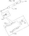
- Figs. 13A-Dare schematic illustrations of an anchor driver 500 and techniques for use with a tissue anchor such as tissue anchor 40.
- Driver 500comprises an anchor-engaging head 502 at a distal end of the driver, and a shaft 504 proximal to the anchor-engaging head.
- Shaft 504is flexible, advanceable (e.g., transcatheterally) through vasculature of a subject, and typically has a length greater than 20 cm, and/or less than 2 m, such as greater than 50 cm and/or less than 1.5 m, e.g., between 90 cm and 1.2m.
- Driver 500may comprise a handle 506 at a proximal end of shaft 504, the handle comprising an adjuster 508 (e.g., a switch or a lever) configured to actuate engaging head 502.
- an adjuster 508e.g., a switch or a lever
- Engaging head 502is configured to be reversibly couplable to tissue anchor 40 (e.g., to a coupling head 42 thereof), so as to facilitate driving of the anchor into tissue of the subject, and subsequent release of the anchor and withdrawal of driver 500 from the subject.
- Actuation of engaging head 502 by adjuster 508typically transitions the engaging head between (i) a closed state in which the engaging head is coupled (e.g., locked) to anchor 40, and (ii) an open state in which the engaging head is configured to release the anchor.
- Engaging head 502comprises a casing 514 that defines a slot 520 and a recess 518 and further comprises a detent 510 that is reversibly movable (e.g., deflectable) within the casing, such as being movable into and out of the recess.
- detent 510is biased toward being disposed within recess 518, such as by at least part of the detent (e.g., a stem portion 516) comprising an elastically-deformable material, and (2) the detent is moved out of the recess by a controller, such as a rod 512, applying a force to the detent, such as by being slid by adjuster 508 into at least part of the recess.
- Slot 520is dimensioned to facilitate coupling of driver 500 to anchor 40 by receiving at least part of eyelet 46 of the anchor.
- Driver 500may be provided pre-coupled to anchor 40 (e.g., a kit may be provided comprising a plurality of drivers, each driver coupled to a respective anchor).
- Driver 500may be coupled to anchor 40 by the operating physician or an assistant thereof.
- Movement of detent 510 out of recess 518transitions engaging head 502 into a closed state thereof in which eyelet 46 is inhibited from exiting slot 520 and therefore in which anchor 40 is coupled to the engaging head. Movement of detent 510 into recess 518 transitions engaging head 502 into an open state thereof in which eyelet 46 is slidable out of slot 520 and thereby in which anchor 40 is decouplable from the engaging head.
- Driver 500is advanced through vasculature of the subject while engaging head 502 is coupled to an anchor 40 as described hereinabove.
- Driver 500is advanced toward tissue 10, and the driver (e.g., at least the engaging head thereof) is rotated so as to screw tissue-coupling element 42 of anchor 40 into the tissue ( Fig. 13A ).
- the drivere.g., at least the engaging head thereof
- anchor 40is typically used to anchor another element, such as an implant, to the tissue.
- anchor 40is typically used to anchor another element, such as an implant, to the tissue.
- tissue-coupling element 42may pierce a portion of an implant and penetrate tissue 10, such that base 48 sandwiches the portion of the implant to the tissue.
- Anchor driver 500may comprise anchor driver 236, described hereinabove with reference to Figs. 9A-C , and/or is used as described for anchor driver 236, mutatis mutandis.
- Driver 500typically rotates anchor 40 until base 48 of the anchor is firmly disposed against tissue 10 ( Fig. 13B ), or against a portion of an implant that is being anchored to the tissue using the anchor.
- base 48may sandwich sleeve 228 and/or sleeve 162 described hereinabove against tissue 10 (e.g., as shown in Figs. 9A-10 , mutatis mutandis ).
- rod 512is moved out of recess 518 (e.g., by being withdrawn proximally), and detent 510 responsively moves into the recess, thereby transitioning driver 500 (e.g., engaging head 502) into the open state thereof ( Fig. 13C ).
- driver 500is withdrawn proximally such that eyelet 46 slides out of slot 520, leaving anchor 40 coupled to tissue 10 ( Fig. 13D ).
- Anchor driver 500may subsequently be discarded, and any additional anchor may be delivered and anchored using a respective additional anchor driver. Additional anchors may be delivered and anchored using the same anchor driver.
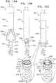
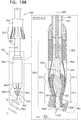
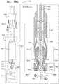
- FIGs. 14-15Care schematic illustrations of a system 2500 for engaging an already-implanted anchor and facilitating extraction (e.g., retrieval) of the anchor from tissue.
- System 2500may comprise elements of, and/or have similar features to, system 100, described hereinabove.
- System 2500may be used with techniques described in US Provisional Application 61/717,303 , which is assigned to the assignee of the present application.
- System 2500comprises an anchor-manipulation tool 2502, comprising an anchor-engaging element 2504, comprising two or more arms 2506 (e.g., arm 2506a and arm 2506b), and a housing 2508. Arms 2506 are typically curved inwardly toward each other, as shown in Figs. 35-37.
- Figs. 15A-Cshow tool 2502 being coupled to a tissue anchor 2532, e.g., prior to extraction of the anchor.
- Anchor 2532comprises a tissue-coupling element 2536 (e.g., a helical tissue coupling element, as shown, or a screw), and coupling head 2534 which defines, or is coupled to, a coupling eyelet 2538, which typically forms a closed loop.
- Tissue anchor 2532may comprise tissue anchor 40, described hereinabove.
- System 2500may comprise one or more anchors 2532 (e.g., tool 2502 and anchors 2532 may specifically be manufactured to be used together).
- Tool 2502is advanced toward anchor 2532 while anchor-engaging element 2504 is in an open position in which arms 2506 are held away from each other ( Fig. 15A ), such that eyelet 2538 of the anchor moves between the arms. Subsequently, element 2504 is closed by moving arms 2506 toward each other. Typically, in the closed configuration, arms 2506 form a closed loop, such that element 2504 and eyelet 2538 generally resemble two links in a chain. For some examples, element 2504 is closed by moving housing 2508 distally, and thereby pushing arms 2506 together ( Fig. 15B ). Alternatively or additionally, arms 2506 may be controlled via a control rod 2510 (shown in Fig. 14 ).
- Housing 2508is slid further distally, such that at least part of eyelet 2538 is disposed within the housing ( Fig. 15C ). This "pushing" movement is typically facilitated by a counterforce (e.g., a "pulling” force) provided by element 2504 on anchor 2532.
- Housing 2508is shaped to define one or more (e.g., two) protrusions 2512, which typically protrude from an inner surface of the housing, into a lumen of the housing.
- portions of the eyeletare disposed in circumferential spaces between protrusions 2512, as shown in state (i) of section A-A of Fig. 36C.
- Housing 2508is subsequently rotated, such that protrusions 2512 engage eyelet 2538, as shown in state (ii) of section A-A of Fig. 36C.
- further rotation of tool 2502e.g., simultaneous rotation of element 2504 and housing 2508 rotates anchor 2532, and thereby facilitates extraction of the anchor from the cardiac tissue.
- System 2500is typically used in a similar manner to that in which system 100 is used. System 2500 may be used as described for system 100 with reference to Fig. 10 , mutatis mutandis.
- tool 2502may engage eyelet 2538 of anchor 2532 at a nonzero angle, due to the chain-link nature of the coupling therebetween.
- protrusions 2512advantageously facilitates the entry of eyelet 2538 into housing 2508 (1) initially at a nonzero angle with respect to the longitudinal axis of the housing, and (2) at a range of rotational positions with respect to the rotational position of the housing, due to the circumferential spaces between the protrusions.
- this configurationmay be contrasted with a hypothetical system in which portions of eyelet 2538 slide into respective slits in the housing, and in which the portions of the eyelet must typically be aligned with the slits before entering the housing.
- Tool 2502may be used to redeploy tissue anchor 2532 into tissue. Alternatively, tool 2502 may be used to initially deploy anchor 2532 into tissue. For example, sleeve 228 and/or sleeve 162 described hereinabove may be preloaded with a plurality of anchors 2532, and tool 2502 may be used to sequentially deploy each anchor into tissue in order to anchor the sleeve to the tissue. For such a case, during the deploying of the plurality of anchors, tool 2502 may also unscrew a given anchor 2532 if the physician determines that the anchor is not positioned correctly.
- anchor 2532comprises a biocompatible material such as stainless steel 316 LVM.
- Anchor 2532may comprise nitinol.
- Anchor 2532may be coated with a non-conductive material.
- FIGs. 16-19are schematic illustrations of a system 1800 for engaging an already-implanted anchor and facilitating extraction (e.g., retrieval) of the anchor from tissue.
- System 1800comprises an anchor-manipulation tool 1802 comprising a tissue-anchor-engaging element 1803 comprising a distal tapered, cone-shaped anchor-engaging tip 1808, a plunger 1820, and one or more engaging structures 1810 disposed adjacently to plunger 1820.
- System 2500is typically used in a similar manner to that in which system 100 is used.
- System 1800may be used as described for system 100 with reference to Fig. 10 , mutatis mutandis.
- System 1800may be used with techniques described in US Provisional Application 61/717,303 and/or in an International Patent Application WO/2014/064694 entitled, "Controlled steering functionality for implant-delivery tool," to Sheps et al., filed on even date herewith, both of which are assigned to the assignee of the present application.
- Two engaging structures 1810are shown by way of illustration and not limitation. Any suitable number of structures 1810 may be used (e.g., 1-4 structures).
- Fig. 16shows an exploded view of tool 1802 in order to illustrate the relationship among the components of tool 1802.
- Fig. 17shows tool 1802 in an assembled state.
- each structure 1810comprises a curved arm 1811 having an inner surface 1815 which defines (1) a proximal portion 1813 which curves toward a longitudinal axis 1807 of tool 1802 (and toward the other arm), and (2) a central curved portion 1814 which curves away from axis 1807.
- Each arm 1811is shaped so as to define and comprises a distal hook 1816 that is moveable in response to movement of arm 1811.
- Arm 1811is moveable in response to proximal and distal movement of plunger 1820 along axis 1807.
- plunger 1820functions as an arm actuator (and therefore as an anchor-engaging-element actuator).
- plunger 1820comprises (1) a distal tapered force applicator 1821 having a proximal portion that is wider than a distal portion of force applicator 1821, and (2) a proximal longitudinal element 1822 coupled to the proximal portion of force applicator 1821. Longitudinal element 1822 is narrower than the proximal portion of force applicator 1821.
- Arms 1811are disposed within an anchor-engaging housing 1804.
- Housing 1804is shaped so as to define one or more (e.g., two) slits 1806. Each slit 1806 facilitates movement of at least a portion of each arm 1811 radially away from axis 1807.
- Housing 1804is shaped so as to define distal tapered anchor-engaging tip 1808 which is configured to engage an engaging head 1862 of a tissue anchor 1832 ( Figs. 18B-C ) by being received within an opening of head 1862.
- plunger 1802in a resting state of tool 1802, plunger 1802 is disposed in a proximal position in which the proximal portion of force applicator 1821 pushes against inner surface 1815 at proximal portion 1813 of arm 1811 such that a force is applied to proximal portion 1813 which keeps arm 1811 and thereby distal hooks 1816 in a closed state.
- each structure 1810may have a proximal-most portion 1812 which is coupled (e.g., by being welded) to a proximal portion of an outer covering 1830.
- proximal portion of applicator 1821applies a force against proximal portion 1813 of arm 1811
- proximal portion of outer covering 1830applies a counterforce against structure 1830 to further maintain hooks 1816 in the closed state.
- a distal portion of covering 1830partially covers slits 1806 and applies additional counterforce against proximal portion 1813 of arm 1811.
- FIG. 18Bshows tool 1802 being manipulated into engaging head 1862 of tissue anchor 1832.
- anchor-engaging tip 1808is advanced within an opening of engaging head 1862.
- Engaging head 1862provides a wall shaped to define the opening, which is shaped to define a funnel having a wide proximal end and a narrower distal end.
- Engaging head 1862is shaped so as to define an undercut 1868 and one or more recesses 1869 in a vicinity of undercut 1868.
- Each recess 1869is configured to receive a respective hook 1816 of arm 1811 of tool 1802.
- Head 1868may provide up to 15 recesses 1869.
- plunger 1820is coupled at a proximal portion thereof to a plunger-manipulating element 1852.
- Element 1852is slidable within a tube 1850, which is coupled at a distal end thereof to respective proximal-most portions 1812 of structures 1810.
- element 1852is advanced distally by sliding within tube 1850, and thereby, element 1852 pushes plunger 1820 distally in a manner in which the proximal portion of force applicator 1821 is pushed beyond proximal portion 1813 of arm 1811 and force applicator 1821 is disposed adjacently to inner surface 1815 of arm 1811 at central curved portion 1814.
- plunger 1820comprises a proximal longitudinal element 1822 coupled to the proximal portion of force applicator 1821.
- Longitudinal element 1822is narrower than the proximal portion of force applicator 1821 such that upon distal advancement of plunger 1820, and thereby, distal advancement of the proximal portion of force applicator 1821 beyond proximal portion 1813 of arm 1811, proximal portions 1813 of arms 1811 incline toward longitudinal element 1822 of plunger 1820.
- curved central portions 1814move radially away from axis 1807, arm 1811 moves, and, responsively to movement of arm 1811, hooks 1816 are distanced from each other by moving radially away from axis 1807.
- Each hook 1816moves within a respective slit 1806.
- the proximal portion of outer covering 1830applies a counterforce against structure 1830 to further maintain hooks 1816 in the closed state.
- a distal portion of covering 1830partially covers slits 1806 and applies additional counterforce against proximal portion 1813 of arm 1811.
- Figs. 18B and 19As shown in Section B-B of Fig. 18B and in Fig. 19 , at least one hook 1816 engages engaging head 1862 of anchor 1832, e.g., by hooking around a portion of the head, such as undercut 1868. In such a configuration, hooks 1816 have not yet been spread apart as far as possible, since force applicator 1821 of plunger 1820 has not yet been moved as far distally as possible. Thus, hooks 1816 are flexible enough to move radially inward and outward in a manner in which tool 1802 may be angled by the operating physician to optimally engage hooks 1816 with recesses 1869 in the vicinity of undercut 1868.
- tool 1802is capable of angular movement in order to optimize engaging of hooks 1816 with undercut 1868.
- Fig. 18Cshows additional radial movement of hooks 1816 in response to additional distal advancement of plunger 1820.
- the distal portion of force applicator 1821applies a force against inner surface 1815 of central curved portion 1814.
- force applicator 1821pushes additionally on surface 1815 of curved portions 1816 of arms 1811 such that hooks 1816 are additionally pushed radially outwardly, such that they firmly engage undercut 1868, as shown in Section C-C.
- Plunger 1820may then be locked into place in order to ensure hooks 1816 remain locked in place under undercut 1868 of engaging head 1862 of anchor 1832.
- axis 1807 of tool 1802is aligned with the longitudinal axis of anchor 1832.
- tool 1802firmly engages anchor 1832 and is then rotated in order to unscrew the already-deployed tissue anchor 1832 from the tissue.
- Tool 1802may be used to redeploy tissue anchor 1832 into tissue.
- tool 1802may be used to initially deploy anchor 1832 into tissue.
- sleeve 228 and/or sleeve 162, described hereinabovemay be preloaded with a plurality of anchors 1832, and tool 1802 may be used to sequentially deploy each anchor 1832 into tissue in order to anchor the sleeve to tissue.
- tool 1802may also unscrew a given anchor 1832 if the physician determines that the anchor is not positioned correctly.
- anchor 1832comprises a biocompatible material such as stainless steel 316 LVM.
- Anchor 1832may comprise nitinol.
- Anchor 1832may be coated with a non-conductive material.
- tool 1802comprises an annular (or tubular) element 1840 which is slidable around tube 1850 and comprises an annular-positioning guide 1842.
- Guide 1842as shown, comprises a plurality of radially-branched tines 1844.
- tines 1844typically define a circumference having a diameter of between 4 and 5 mm (e.g., 4.5 mm) which is typically at least 1.2 times (e.g., 1.5 times) greater than a largest cross-sectional diameter of tool 1802.
- Fig. 19shows the guided positioning of tool 1802 using guide 1842 of annular element 1842.
- Tines 1844are configured to surround engaging head 1862 of anchor 1832 in a manner which guides tool 1802 and centralizes (e.g., aligns) anchor-engaging tip 1808 within the opening of engaging head 1862.
- annular element 1840is slid distally in order to surround at least a portion of engaging head 1862.
- annular element 1840may be slid proximally away from engaging head 1862 of anchor 1832.
- System 1800is typically used in a similar manner to that in which system 100 and/or system 2500 is used.
- System 1800may be used as described for system 100 with reference to Fig. 10 , mutatis mutandis.
- Annular element 1840may be used to increase a working diameter for tool 1802 by opening a portion of the sleeve 228 and/or sleeve 162, e.g., a kinked portion of the sleeve.
- annular-positioning guide 1842helps centralize (e.g., align) anchor-engaging tip 1808 within engaging head 1862 of anchor 1832.
- Figs. 20A-Care schematic illustrations of a technique for use with a tool 80 and anchor 40.
- tools 80 and 380are configured to be articulatably coupled to anchor 40, to subsequently inhibit this articulation, and to subsequently de-anchor and remove the anchor.
- Figs. 4E and 11Eshow anchor 40 being withdrawn proximally by tool 80 and tool 380, respectively, while this articulation is inhibited (e.g., in a rigidly-coupled state).
- Figs. 10A-Cutilize tool 80 as an illustrative example, but the same techniques are applicable to tool 380, mutatis mutandis.
- Fig. 20Ashows eyelet 46 of anchor 40 disposed within housing 82 of tool 80, while arms 92 are in the retracted position thereof.
- housing 82inhibits articulation between tool 80 and anchor 40 (e.g., the tool and anchor are rigidly coupled to each other).
- a rigid length d10is defined between (1) the distal end of tissue-engaging element 42 of anchor 40, and (2) a part of tool 80 (e.g., a part of housing 82) that is proximal to crest 43 of eyelet 46 of the anchor.
- rigid length d10is defined between the distal end of tissue-engaging element 42, and a part of tool 80 that is proximal to most or all of arms 92, such as between the distal end of the tissue-engaging element and a proximal end of housing 82.
- Fig. 20Bshows eyelet 46 of anchor 40 disposed outside of housing 82 of tool 80, while arms 92 are in the intermediate position thereof, i.e., in the articulatably-coupled state described hereinabove.
- a rigid length d11is defined between (1) the distal end of tissue-engaging element 42 of anchor 40, and (2) crest 43 of eyelet 46 of the anchor.
- a second rigid length d12is defined between distal end 83 of housing 82, and a part of tool 80 that is proximal to most or all of arms 92, such as between the distal end of the housing and a proximal end of the housing.
- Rigid length d12may be defined between a distal end of arms 92 and the part of tool 80 that is proximal to most or all of arms 92. Typically, both rigid length d11 and rigid length d12 are smaller than rigid length d10.
- a cathetere.g., catheter 214.
- housing 82 and anchor 40are able to traverse more greatly-bent portions of catheter 14 than they would in the rigidly-coupled state.
- Transcatheter movement of tool 80 and anchor 40 while articulatably coupled to each othermay be used to facilitate both delivery and retrieval of anchors.
- Tool 80may be configured to maintain the tool and anchor 40 in the articulatably-coupled state (e.g., to prevent rigid coupling therebetween).
- tool 80may comprise a stopper, configured to prevent eyelet 46 from entering (e.g., fully entering) compartment 86.
- housing 82may be configured (e.g., shaped) not to receive eyelet 46 (e.g., the housing may be configured to receive only arms 92 and not eyelet 46).
- Figs. 21A-Care schematic illustrations of a tool 680 for use with tissue anchor 40.
- tool 680for use with tissue anchor 40.
- tool 680typically, tool 680 and components thereof are identical to tool 80 and identically-named components thereof, except where noted.
- techniques described herein for use with tool 80may typically be used with tool 680, mutatis mutandis.
- Tool 680is typically configured, and used, to retrieve anchor 40 from tissue of the subject (e.g., after the anchor has been previously implanted and/or used to facilitate implantation of an implant). Tool 680 may also be configured and/or used to implant anchor 40.
- Tool 680comprises a housing 682 that has an inner surface that defines a generally cylindrical compartment 686 that has an opening 688 at a distal end 683 of the housing.
- Tool 80further comprises an anchor-engaging element 691 comprising one or more (e.g., two) arms 692 (e.g., a first arm 692a and a second arm 692b) that define a space 696 therebetween.
- At least one armis shaped (e.g., curved) to define a concavity 703.
- first arm 692amay be shaped to define concavity 703.
- Arm 692amay comprise arm 92 described hereinabove.
- Arm 692bis not shaped to define a concavity, and is typically generally straight.
- a distal portion 694b of arm 692bmay deflect outward from a longitudinal axis of the tool, e.g., so as to facilitate movement of the arm around bar 44 of eyelet 46 of anchor 40.
- Fig. 21AMovement of housing 682 with respect to arms 692 moves the arms between an extended position ( Fig. 21A ), an intermediate position ( Fig. 21B ), and a retracted position ( Fig. 21C ), e.g., as described for tool 80 with reference to Figs. 3A-C , mutatis mutandis.
- Figs. 21A-Cshow stages in the transition of arms 692 from the extended position ( Fig. 21A ) to the retracted position ( Fig. 21C).
- 21Billustrates that as the arms move from the extended position to the retracted position via the intermediate position, the arms form a loop before assuming the retracted position (e.g., before the completely enter compartment 86), e.g., as described for tool 80 with respect to Figs. 3A-C , mutatis mutandis.
- the armsIn the intermediate position, the arms form a loop that shapes space 696 to define an aperture 697, e.g., as described for tool 80 with respect to Figs. 3A-C , mutatis mutandis.
Landscapes
- Health & Medical Sciences (AREA)
- Surgery (AREA)
- Life Sciences & Earth Sciences (AREA)
- Medical Informatics (AREA)
- Animal Behavior & Ethology (AREA)
- Engineering & Computer Science (AREA)
- Biomedical Technology (AREA)
- Heart & Thoracic Surgery (AREA)
- Veterinary Medicine (AREA)
- Molecular Biology (AREA)
- Nuclear Medicine, Radiotherapy & Molecular Imaging (AREA)
- General Health & Medical Sciences (AREA)
- Public Health (AREA)
- Rheumatology (AREA)
- Reproductive Health (AREA)
- Vascular Medicine (AREA)
- Surgical Instruments (AREA)
Description
- The present disclosure relates in general to medical devices. More specifically, the present disclosure relates to tissue anchors and tool for manipulation of tissue anchors, such as for percutaneous use.
- Tissue anchors are used to facilitate implantation of medical implants, such as by coupling such implants to tissue. A tissue anchor may be driven through the implant and into the tissue while the implant is held in place. Alternatively, the tissue anchor may be implanted before introduction of the medical implant, and the medical implant subsequently coupled to the tissue anchor.
US Application 12/608,316 US 2011/0106247 provides apparatus for use with an implant, the apparatus including a tissue anchor, which comprises a distal tissue coupling element, which is configured to penetrate cardiac tissue, and a proximal implant-penetrating element configured to penetrate the implant. The proximal implant-penetrating element is shaped so as to define a passage therethrough, which passage has at least two openings that are within 1 mm of a proximal end of the implant-penetrating element. The apparatus also comprises a cord configured to be removably passed through the passage.- Tissue anchor apparatus, and techniques for use thereof, are described. A tool is described for manipulating tissue anchors. The tool may be configured for retrieval of already-implanted tissue anchors. The tool may be configured to be coupled to a tissue anchor at a non-zero angle with respect to the tissue anchor, and to subsequently be aligned with the tissue anchor. The tool may be configured to be advanced through a sleeve of an implant that has been implanted using tissue anchors, and to de-anchor at least one of the tissue anchors, thereby de-anchoring at least part of the sleeve from the tissue.
- A tissue anchor is described having a helical tissue-coupling element and an engaging head that comprises an eyelet. The tool may be configured to be initially articulatably coupled to the tissue anchor (e.g., to the eyelet), and to be subsequently rigidly-coupled to the tissue anchor. The tool may be configured to couple to the eyelet such that, together, the eyelet and an anchor-engaging element of the tool resemble links in a chain.
- An anchor driver is described for implanting the tissue anchor.
- The present invention which is in its broadest sense defined by the appended claims will be more fully understood from the following detailed description, taken together with the drawings, in which:
Figs. 1A-B ,2A-B , and3A-C are schematic illustrations of a tissue anchor and a tool for use with the tissue anchor;Figs. 4A-E ,5A-B , and6A-E are schematic illustrations of a system comprising the tissue anchor and the tool, and of use of the tool to retrieve the anchor from tissue of a subject;Fig. 7 is a schematic illustration of a proximal portion of the tool, including an extracorporeal controller;Fig. 8 is a schematic illustration of arms of the tool;Figs. 9A-C are schematic illustrations of a procedure for implanting an annuloplasty ring structure to repair a mitral valve;Figs. 10A-B are schematic illustrations of the tool being used to retrieve an anchor from within a lumen of an implant;Figs. 11A-E are schematic illustrations of another tool and techniques for use with a tissue anchor;Figs. 12A-E are schematic illustrations of another tool and techniques for use with a tissue anchor;Figs. 13A-D are schematic illustrations of an anchor driver and techniques for use with a tissue anchor;Figs. 14 and15A-C are schematic illustrations of a system for engaging an already-implanted anchor and facilitating extraction (e.g., retrieval) of the anchor from tissue;Figs. 16, 17 ,18A-C , and19 are schematic illustrations of a system for engaging an already-implanted anchor and facilitating extraction (e.g., retrieval) of the anchor from tissue;Figs. 20A-C are schematic illustrations of a technique for use with a tool and a tissue anchor; andFigs. 21A-C are schematic illustrations of a tool for use with a tissue anchor.- Reference is made to
Figs. 1A-3C , which are schematic illustrations of atissue anchor 40 and atool 80 for use with the tissue anchor.Anchor 40 is shown in two rotational views inFigs. 1A-B , respectively.Anchor 40 comprises a tissue-coupling element 42, and an engaging head comprising acoupling eyelet 46 defined by a bar (e.g., a shaft) 44. Typically, tissue-coupling element 42 comprises a helical tissue-coupling element, configured to be screwed into, and optionally screwed out of, tissue of a subject. Eyelet 46 provides a coupling interface fortool 80 and/or another tool. As described hereinbelow,tool 80 is typically configured, and used, to retrieveanchor 40 from tissue of the subject (e.g., after the anchor has been previously implanted and/or used to facilitate implantation of an implant).Tool 80 may also be configured and/or used to implantanchor 40. A different tool may be used to implantanchor 40. Anchor 40 has a central longitudinal axis a1, from a distal end of tissue-coupling element 42 to a proximal end ofeyelet 46. Typically, a central helix axis of helical tissue-coupling element 42 is coaxial with axis a1.Eyelet 46 typically defines a plane a4 (see alsoFig. 6A ), on which the central helix axis and/or axis a1 typically lie. Typically, a height d1 ofeyelet 46 is at least 80 percent as great as a width d2 of the eyelet (e.g., approximately equal to width d2, or greater than width d2, such as at least 50 percent greater than width d2). Typically,bar 44 defines an arch portion ofeyelet 46, and anchor 40 (e.g., the engaging head thereof) comprises abase 48 that defines a base portion of the eyelet, and couples the eyelet to tissue-coupling element 42. The arch portion of the eyelet is thereby oriented such that acrest 43 of the arch portion is further from tissue-coupling element 42 than is abase 45 of the arch portion. The shape (e.g., curvature) of the arch is typically such that the arch continues to widen for most, if not all, of its length fromcrest 43 tobase 45. Typically, any portion ofbar 44 that is parallel to longitudinal axis a1 has a height along the longitudinal axis that is less than 50 percent (e.g., less than 20 percent, such as less than 10 percent) of height d1 of the eyelet. Such portions may be considered 'imposts' of the arch portion that are less than 50 percent (e.g., less than 20 percent, such as less than 10 percent) of the overall height of the arch portion. The arch portion of the eyelet may have a generally parabolic shape.Bar 44 has a thickness (e.g., a bore) d3.Figs. 2A-B show side and distal-end views, respectively, of a distal portion oftool 80.Tool 80 comprises ahousing 82 that has aninner surface 84 that defines a generallycylindrical compartment 86 that has a transverse width (e.g., a diameter) d4. Anopening 88 at adistal end 83 of the housing provides fluid communication betweencompartment 86 and the outside of the housing. Two ormore protrusions 90 protrude radially inward frominner surface 84 intocompartment 86, such that a distance d5 across the compartment between the protrusions is smaller than width d4 of the compartment, and also smaller than width d2 ofeyelet 46 ofanchor 40. Width d4 ofcompartment 86 is typically slightly greater than width d2 ofeyelet 46, so as to accommodate the eyelet without allowing enough space for the eyelet to move significantly within the compartment. For example, width d4 may be at least 5 percent, less than 30 percent, and/or between 5 and 30 percent greater (e.g., 10-20 percent greater) than width d2.Tool 80 further comprises an anchor-engagingelement 91 comprising one or more (e.g., two)arms 92, each arm defining aproximal stem portion 93 and distal portion 94 (e.g., a distal hook portion), and the arms typically curving inwardly toward each other so as to define aspace 96 therebetween (e.g., between respective proximal stem portions). That is, the curve of each arm defines aconcavity 103, and the concavity of each arm faces the concavity of the other arm, so as to define at least part ofspace 96. Alternatively, stemportion 93 may be generally straight. It is to be noted, that even when stemportion 93 is generally straight,arm 92 would typically still define a concavity at asite 104 whereportion 93 meetsdistal portion 94.Figs. 2A-B (andFig. 3A ) show arms in an extended position thereof, in which at least the distal portion of each arm protrudes out of opening 88 and is disposed outsidecompartment 86, and a gap between the distal portions has a width d6 that is great enough for at least part ofbar 44 to move through, intospace 96.- Typically, width d6 is greater than thickness d3 of
bar 44 ofeyelet 46 of anchor 40 (e.g., at least 5 times as great as thickness d3, such as at least 10 times as great as thickness d3, such as at least 20 times as great as thickness d3). Width d6 is further typically greater than width d4 ofcompartment 86, e.g., at least 1.5 times as great, less than 4 times as great, and/or between 1.5 times and 4 times as great. Arms 92 (e.g.,portion 93 and/orportion 94 thereof) have a thickness d7 that is typically less than 0.5 times as great (e.g., less than 0.2 times as great, such as less than 0.1 times as great) as width d6, and/or less than width d4 (e.g., less than 0.5 times as great as width d4, such as less than 0.2 times as great as width d4). - A plane a5 on which
arms 92 lie may typically be disposed at least 20 degrees, up to 90 degrees, and/or between 20 and 90 degrees with respect to a transverse axis a3 betweenprotrusions 90. For example, and as shown inFig. 2B , plane a5 may be disposed at about 45 degrees with respect to axis a3. This orientation is discussed hereinbelow with respect toFigs. 6A-E . - In the extended position, stem
portion 93 of eacharm 92 typically protrudes distally away fromhousing 82 and outward from a longitudinal axis a2 oftool 80, anddistal portion 94 of each arm protrudes from a distal end of the stem portion and inward toward the longitudinal axis. Further typically,distal portion 94 of each arm protrudes from the distal end ofstem portion 93 distally away from the housing. Distal portion 94 (e.g., an inner surface thereof) is disposed at an angle alpha A with respect to longitudinal axis a2, angle alpha_A typically being greater than 40 degrees, less than 85 degrees, and/or between 40 and 85 degrees (e.g., between 50 and 80 degrees, such as between 50 and 70 degrees and/or between 70 and 80 degrees). Due at least in part to these geometries,arms 92 typically do not define effective hooks while in the extended position. It is hypothesized that such a configuration reduces a likelihood ofarms 92 inadvertently hooking to tissue or apparatus within the body of the subject. Arms 92 further have a retracted position in which at least part ofdistal portion 94 of each arm is typically disposed insidecompartment 86, as shown inFig. 3C . In the retracted position,arms 92 define a loop (e.g.,distal portions 94 are in contact with each other), thereby shapingspace 96 to define an aperture 97.Figs. 3A-C show stages in the transition ofarms 92 from the extended position (Fig. 3A ) to the retracted position (Fig. 3C). Fig. 3B shows an intermediate position ofarms 92 that is partway between the extended position and the retracted position, illustrating that as the arms move from the extended position to the retracted position, the arms form the loop before assuming the retracted position (e.g., beforearms 92 completely enter compartment 86).- As
arms 92 move from the extended position toward the retracted position, the arms deflect toward each other such thatdistal portions 94 become closer to each other (e.g., such that a distance between the distal portions is smaller than thickness d3 ofbar 44. Typically,distal portions 94 are at least 10 times further (e.g., at least 20 times further) from each other when in the extended position than when in the retracted position. Further typically, in at least the retracted position (and still further typically also in the intermediate position), the distal portion of one arm is in contact with the distal portion of another (e.g., the other) arm. Each distal portion may be shaped to define a beveled edge, so as to facilitate contact (e.g., mating) of the distal portions. For example, when the arms move into the intermediate position and/or the retracted position, at least part of the beveled edge of one arm moves past at least part of the beveled edge of the other arm. The beveled edges and the resulting mating is shown most clearly inFig. 3B . - As
arms 92 move toward the intermediate position and/or the retracted position, the angle at whichdistal portion 94 is disposed with respect to longitudinal axis a2 approaches, and typically passes, 90 degrees, such that each arm forms a hook (e.g., as shown inFigs. 3B-C ). Typically, this angle atleast reaches 90 degrees beforedistal portions 94 contact each other. It is hypothesized that such a configuration facilitates preliminary coupling (e.g., hooking) of asingle arm 92 to eyelet 46 before the arms reach the intermediate and/or retracted position. This may be advantageous, for example, when couplingtool 80 to a tissue anchor that is not disposed close to longitudinal axis a2 oftool 80. Tool 80 further comprises anextracorporeal controller 110, which comprises ahandle 112 and anadjuster 114, such as a switch or a lever.Adjuster 114 is configured to movearms 92 between the extended and retracted states. As described with reference toFigs. 4A-E ,arms 92 are typically moved between the extended and retracted states by movinghousing 82 distally while the arms remain stationary (e.g., with respect to anchor 40 and/or tissue of the subject). Such a configuration facilitates coupling ofarms 92 to eyelet 46 of the anchor with a reduced likelihood of the arms inadvertently moving away from the eyelet. As described in more detail hereinbelow with reference toFig. 7 , typically (1)adjuster 114 is coupled tohousing 82 and is configured to reversibly move the housing further and closer fromhandle 112, and (2) handle 112 is coupled toarms 92 such that a distance alongtool 80 between the handle and the housing is fixed.- As shown in
Figs. 3A-C ,adjuster 114 is moved so as to movearms 92 between the extended position and the retracted position (e.g., via the intermediate position). Typically, and as described in more detail with reference toFig. 7 , a tactile and/or visual indicator indicates at least a state ofadjuster 114 in whicharms 92 are in the intermediate position (as shown inFig. 3B ). Further typically,controller 110 is configured to partially holdadjuster 114 in one or more states, such as in the state in whicharms 92 are in the intermediate position. - Reference is made to
Figs. 4A-E ,5A-B , and6A-E , which are schematic illustrations of asystem 100, comprisingtissue anchor 40 andtool 80, and of use of the tool to retrieve the anchor fromtissue 10 of the subject.Fig. 4A showsanchor 40 having been previously implanted in tissue 10 (e.g., to facilitate implantation of an implant; not shown inFig. 4A , but a non-limiting illustrative example is described with reference toFigs. 9A-10 ).Tool 80 is advanced towardanchor 40 witharms 92 in the extended position, such thatarms 92 pass aroundbar 44 of eyelet 46 (i.e., such that the bar passes through the gap between the distal portions of the arms and into the space between the arms).Housing 82 is moved distally over at least part of arms 92 (e.g., such that the housing presses on a housing-contactingsurface 105 of the arms), such that the arms move into the intermediate position, trappingbar 44 within aperture 97 defined by the loop formed by the arms (Fig. 4B ). That is, aperture 97 acts as or defines an eyelet-retention area. It is to be noted that in this state (1)arms 92 are articulatably coupled toeyelet 46, (2) the arms (e.g., the loop defined thereby) andeyelet 46 generally resemble links in a chain (e.g., this state is an articulatably-coupled state), and (3)eyelet 46 inhibits movement of tool 80 (e.g., anchor-engagingelement 91 thereof) away fromtissue anchor 40. - Typically, aperture 97 (1) defines an area that is at least 10 times greater (e.g., at least 20 times greater, such as at least 40 times greater) than that of a transverse cross-sectional area of
bar 44 ofanchor 40, (2) has a width d8 (seeFig. 3B ; e.g., a smallest width and/or a width transverse to longitudinal axis a2) that is at least 3 times greater (e.g., at least 5 times greater, such as at least 8 times greater) than thickness d3 ofbar 44, and/or (3) has a width d8 that is greater (e.g., at least 2 times greater e.g., at least 4 times greater, such as at least 10 times greater) than a depth of the aperture, which is defined by thickness d7 ofarms 92. That is, aperture 97 is typically (1) wider than bar 44 (e.g., at least 3 times wider, e.g., at least 5 times wider, such as at least 8 times wider), and/or (2) wider than itself is deep (e.g., at least 2 times wider, e.g., at least 4 times wider, such as at least 10 times greater). These relative dimensions of aperture 97 andbar 44 facilitate the articulatable coupling oftool 80 to eyelet 46, and/or coupling oftool 80 to the eyelet at a wide range of possible angles of attack, e.g., as described hereinbelow. - Tool 80 (e.g., anchor-engaging
element 91 thereof) may comprise only one arm, and bar 44 may be trapped by the one arm, e.g., by being hooked by the one arm, and/or by being trapped between the one arm andinner surface 84 ofcompartment 86.Tool 80 may comprise two arms, but only one of the arms defines a concavity. For example, the other one of the arms may be straight, and the space between the arms is shaped to define an asymmetric aperture whendistal portion 94 of the arm that defines the concavity comes into contact with a distal portion of the straight arm (e.g., as described with reference toFig. 21 ,mutatis mutandis). - It is to be further noted that
tool 80 is shown having been advanced toward, and coupled to eyelet 46 with a longitudinal axis a2 of the tool (e.g., of housing 82) at a nonzero angle of attack with respect to longitudinal axis a1 ofanchor 40.Fig. 5A more clearly shows thattool 80 is configured to engage (e.g., to be coupled to) eyelet 46 at a variety of angles of attack, including deflection in a plane defined by longitudinal axis a1 of the tissue anchor, and around axis a1. For example,tool 80 may be coupled to eyelet 46 while axis a2 is generally parallel totissue 10, perpendicular to the tissue, or at any angle of attack therebetween. That is,tool 80 is configured to engage the coupling eyelet at at least 180 degrees of deflection of longitudinal axis a2 with respect to longitudinal axis a1 (e.g., in a plane on which axis a1 lies). Similarly,tool 80 may be coupled to eyelet 46 at at least most (e.g., all) rotational angles of attack around longitudinal axis a1, e.g., at at least 300 degrees of deflection of axis a2 around axis a1. This may mean that whentool 80 is advanced from a given direction (e.g., due to anatomical and/or other constraints), the tool is couplable to eyelet 46 at at least most (e.g., all) rotational angles of attack ofanchor 40 around its longitudinal axis. - The above possible angles of attack of
tool 80 may also be translated into three-dimensional terms. For example, the possible angles of attack oftool 80 typically, together, define a three-dimensional angular span of at least 1 steradian (e.g., at least 3 steradians, such as at least 7 steradians) aroundeyelet 46. Such a span is illustrated schematically, by way of example, asspan 102 inFig. 5B . - While
system 100 is in the articulatably-coupled state (e.g., whiletool 80 is articulatably coupled to anchor 40),tool 80 is deflectable with respect toanchor 40. Typically, in this state,tool 80 is deflectable into any of the angles described hereinabove as angles of attack. For example,tool 80 is typically deflectable into any angle that lies within the three-dimensional angular span(s) that are described with reference toFigs. 5A-B , such as span 102 (e.g., a three-dimensional angular span that is at least 1 steradian, such as at least 3 steradians, such as at least 7 steradians). - When an angle between axes a1 and a2 is relatively large,
tool 80 may subsequently be manipulated so as to reduce the angle between axes a1 and a2, e.g., to at least in part align the tool and anchor 40 (Fig. 4C ). For example,tool 80 may be rotated, pulled slightly proximally (e.g., along axis a2) and/or moved orthogonally with respect to axis a2. Typically,tissue 10 is sufficiently soft and/or flexible that the tissue responsively deforms (e.g., temporarily), allowinganchor 40 to move into a position in which axes a1 and a2 are more closely aligned. - Subsequently,
arms 92 are moved into the retracted position, typically byhousing 82 being slid over the arms (e.g., whilearms 92 remain stationary), and thereby also over at least part of (e.g., most of, or all of) eyelet 46 (Fig. 4D ).Housing 82 thereby typically functions as an arm actuator. By movingarms 92 into the retracted position, at least part ofeyelet 46 moves into the compartment ofhousing 82. Although the retracted position is described hereinabove as having at least part ofdistal portion 94 of each arm typically disposed insidecompartment 86, as shown inFig. 3C , it is to be noted that for some cases, distal portions do not entercompartment 86. For example, in the retracted position,distal portions 94 may remain just outside ofcompartment 86, e.g., sufficiently close to the compartment that at least part ofeyelet 46 moves into the compartment when the arms move into the retracted position. Housing 82 is configured to receiveeyelet 46 at a plurality of rotational positions (e.g., a continuum of rotational positions) with respect to the housing. Portions ofbar 44 ofeyelet 46 become disposed in a circumferential space betweenprotrusions 90. For example, and as shown inFig. 6A , which is a cross-sectional view ofsystem 100 witheyelet 46 disposed withincompartment 86 of housing 82 (as indicated by section "VIA-VIB" inFig. 4D ), transverse axis a3 betweenprotrusions 90 of the housing may be disposed at a continuum of rotational positions with respect to plane a4 defined byeyelet 46. Typically, this continuum of rotational positions spans at least 90 degrees (e.g., at least 150 degrees, such as almost 180 degrees) around axis a2.Housing 82 may be configured to receiveeyelet 46 at one or more continua of rotational positions of plane a4, that span a total of at least 270 degrees around longitudinal axis a2.Fig. 6A schematically shows rotational positions in which eyelet 46 may be disposed, by way of "phantom" portions ofbar 44.- Although as described in the
above paragraph housing 82 is configured to receiveeyelet 46 at a plurality (e.g., a continuum) of rotational positions with respect to the housing, the orientation of arms 92 (e.g., plane a5 thereof) with respect to protrusions 90 (e.g., axis a3 therebetween) may bias the eyelet (e.g., plane a4 thereof) to be oriented in a particular rotational position with respect to the housing. For example, and as shown inFig. 6A , the arrangement of protrusions may bias plane a4 toward anangular span 91 that is generally centered orthogonally to axis a5.Fig. 6A schematically shows a rotational position of the eyelet (e.g., into which the eyelet is biased) by way of shaded portions ofbar 44, disposed generally central withinangular span 91. It is hypothesized that such biasing may inhibit axis a4 from aligning with axis a3 (which might otherwise inhibit entry ofeyelet 46 intocompartment 86 of housing 82). It is further hypothesized that such biasing may advantageously alignprotrusions 90 andeyelet 46 in advance of rotation of anchor 40 (which is described hereinbelow with reference toFigs. 4E and6A-E). Fig. 6B shows, for clarity, the same arrangement of elements asFig. 6A , but without the "phantom" portions ofbar 44, and with less annotation. - As described hereinabove, in the intermediate position,
arms 92 are articulatably coupled toeyelet 46. The compartment ofhousing 82 is typically dimensioned such that the eyelet fits generally snugly therewithin. Thereby movement ofeyelet 46 into the compartment ofhousing 82 typically inhibits articulation of the eyelet with respect to the arms. The state ofsystem 100 shown inFig. 4D (and Fig. 4E ) may thereby, for some cases, be a rigidly-coupled state. Typically, the dimensions and/or shape of eyelet 46 (e.g., ofbar 44 thereof), such as those described with reference toFigs 1A-B , facilitate entry of the eyelet into the compartment ofhousing 82, such as by facilitating alignment ofanchor 40 withtool 80. For example, curvature of the arch portion ofeyelet 46 may facilitate alignment of axes a1 and a2 as the eyelet is moved into the compartment ofhousing 82. - Subsequently, as shown in
Fig. 4E , and as shown in cross section inFigs. 6C-E ,housing 82 is rotated so as to rotate, and thereby unscrew, anchor 40 fromtissue 10. Initially, rotation ofhousing 82 movesprotrusions 90 until they engage (e.g., contact and press against) bar 44 of eyelet 46 (Figs. 6C-D ). Further rotation ofhousing 82 applies a de-anchoring rotational force to eyelet 46, thereby rotating the eyelet andanchor 40 as a whole, and thereby unscrewing the anchor from tissue 10 (Fig. 6E ). It is to be noted that, (1) whereas a proximal/pulling force is applied to anchor 40 by a first element of tool 80 (i.e., anchor-engagingelement 91, e.g.,arms 92 thereof), a rotational/torque force is applied by a second element of the tool (i.e.,housing 82, e.g.,protrusions 90 thereof). That is, pulling and rotation ofanchor 40 are conducted by two distinct elements oftool 80 that are movable (e.g., longitudinally slidable) with respect to each other. It is to be further noted that rotatinghousing 82 in the reverse direction may screwanchor 40 intotissue 10.Tool 80 may be used tore-anchor anchor 40 intotissue 10, or may even be used for the initial anchoring of the anchor. - It is to be noted that, although
Figs. 4A- 5B show anchor 40 anchored alone totissue 10,anchor 40 is typically used to anchor another element, such as an implant, to the tissue. For example, and as shown inFigs. 9A-10 mutatis mutandis, tissue-coupling element 42 may pierce a portion of an implant and penetratetissue 10, such thatbase 48 sandwiches the portion of the implant to the tissue. - Reference is made to
Fig. 7 , which is a schematic illustration of a proximal portion oftool 80, includingextracorporeal controller 110, which comprises handle 112 andadjuster 114. As described briefly hereinabove with reference toFigs. 3A-C , typically (1)adjuster 114 is coupled tohousing 82 and is configured to reversibly move the housing further and closer fromhandle 112, and (2) handle 112 is coupled toarms 92 such that a distance alongtool 80 between the handle and the housing is fixed.Adjuster 114 may be coupled to a tubular longitudinal member 116 (e.g., via a cam 118), the tubular longitudinal member being slidable with respect to handle 112, and a distal end of the tubular longitudinal member being coupled tohousing 82. The distal portion of tubularlongitudinal member 116 may comprise and/or definehousing 82. For such cases, handle 112 is typically coupled (e.g., fixedly coupled) to a longitudinal member 120 (e.g., via afastener 122, such as a set screw), a distal end of the longitudinal member being coupled (e.g., fixedly coupled) toarms 92, and tubularlongitudinal member 116 is slidable over the longitudinal member. Typically,longitudinal member 120 is disposed through tubularlongitudinal member 116. Typically, and as shown inFig. 7 , handle 112 is coupled to a proximal end oflongitudinal member 120 that is exposed from a proximal end of tubularlongitudinal member 116. Tool 80 is typically used to retrieveanchor 40 percutaneously (e.g., transluminally).Housing 80, tubularlongitudinal member 116 andlongitudinal member 120 are thereby configured to be percutaneously advanced to a site at which anchor 40 is implanted. For example, whentool 80 is configured to transluminally retrieveanchor 40,housing 80, tubularlongitudinal member 116 andlongitudinal member 120 are dimensioned to fit within the blood vessel(s) through which they are to be advanced, and the tubular longitudinal member and the longitudinal member are sufficiently flexible to follow the transluminal route.- Typically,
extracorporeal controller 110 comprises and/or defines anindicator 124 that indicates a state ofadjuster 114, and thereby the position ofarms 92.Indicator 124 may comprise a visual indicator, such as markings, and/or may comprise a tactile indicator, such as graduatedridges 126 with which a part ofadjuster 114 interfaces.Indicator 124 typically indicates at least a state ofadjuster 114 in whicharms 92 are in the intermediate position in which they define the loop but are not in the retracted position.Indicator 124 may also indicate one or more states ofadjuster 114 in whicharms 92 are between the extended position and the intermediate position (e.g., partially closed), e.g., so as to facilitate advancement oftool 80 through a narrow lumen. Indicator 124 (e.g.,ridges 126 thereof) may be configured to partially holdadjuster 114 in one or more states, such as in the state in whicharms 92 are in the intermediate position. - Reference is again made to
Figs. 4A-E ,5A-B , and6A-E . Eacharm 92 may have a generally sigmoid shape, in which (1) an inwardly convexproximal portion 99 of the arm (e.g., an inwardly convex proximal portion of stem portion 93) curves away from axis a2, and (2) an inwardly concavedistal portion 101 of the arm (e.g.,distal portion 94, and/or an inwardly convex distal portion of stem portion 93) curves at least in part back toward axis a2, and definesconcavity 103 described hereinabove. It is hypothesized that this configuration facilitates at least some of the functionalities described herein. For example: - The outward curvature of
portion 99 may facilitate slidinghousing 82 thereover, so as to movearms 92 into the intermediate position. That is,portion 99 may have a housing-contactingsurface 105 on whichhousing 82 presses when the housing slides overportion 99. For example, the outward curvature ofportion 99 may maintain, during movement ofhousing 82 overarm 92, a generally constant interface angle alpha_C between the housing and the part of the arm (e.g., the part of surface 105) that is currently in contact with the housing. It is hypothesized that this thereby maintains a constant resistance to movement ofhousing 82 overarm 92, thereby facilitating control by the operating physician. - The outward curvature of
portion 99 and/or the inward curvature ofportion 101 may facilitate the arms forming the loop and aperture 97 before assuming the retracted position (e.g., beforearms 92 completely enter compartment 86). - Reference is made to
Fig. 8 , which is a schematic illustration ofarms 92. Typically, theproximal stem portion 93 ofarms 92 are coupled to each other (e.g., fixedly coupled to each other, or articulatably coupled to each other). As shown inFig. 8 , a forkedmember 140, comprising a continuous piece of material, may define arms 92 (e.g., each tine of the forked member defining a respective arm).Arms 92 may be biased toward deflecting away from each other, such as by forkedmember 140 comprising a resilient material. For some such cases, the resilient material may allowarms 92 to progressively bend and/or deflect toward each other as the arms are progressively moved intocompartment 86 of housing 82 (e.g., as the arms progressively move toward the intermediate and/or retracted position thereof). Arms 92 are typically disposed on a plane a5 (e.g., when in a relaxed and/or unconstrained state).Arms 92 may be more resistant to bending in plane a5 (i.e., in-plane) than away from plane a5 (i.e., off-plane). For some such cases, when forkedmember 140 definesarms 92 and comprises a resilient material, the material is more flexible off-plane than it is in-plane.Fig. 8 shows inphantom arms 92 being bent off-plane. It is hypothesized that this relatively high off-plane flexibility ofarms 92 facilitates decoupling ofarms 92 from an element to which they are coupled (e.g., to which they are inadvertently coupled), such as by moving (e.g., rotating)tool 80 in order to bend and thereby release the arm from the element.- Reference is now made to
Figs. 9A-C , which are schematic illustrations of a procedure for implanting anannuloplasty ring structure 222 to repair amitral valve 230.Annuloplasty ring structure 222 is used to repair a dilated valve annulus of an atrioventricular valve, such asmitral valve 230. The annuloplasty ring may be configured to be placed only partially around the valve annulus (e.g., to assume a C-shape), and, once anchored in place, to be contracted so as to circumferentially tighten the valve annulus. The annuloplasty ring comprises aflexible sleeve 228 and a plurality ofanchors 40. An anchor deployment manipulator 261, comprising ananchor driver 236 and adeployment element 238 at a distal end of the anchor driver, is advanced into a lumen ofsleeve 228, and, from within the lumen, deploys the anchors through a wall of the sleeve and into cardiac tissue, thereby anchoring the sleeve around a portion of the valve annulus. Annuloplasty ring structure 222 may be implanted,mutatis mutandis, using techniques described inUS Application 12/437,103, filed May 7, 2009 US 2010/0286767 , and/orUS Application 12/689,635, filed January 19, 2010 US 2010/0280604 , both of which are assigned to the assignee of the present application.Annuloplasty ring structure 222 may be implanted,mutatis mutandis, using techniques described inUS Provisional Application 61/717,303Annuloplasty ring structure 222 comprises anadjusting mechanism 246. The adjusting mechanism comprises a rotatable structure, such as a spool, arranged such that rotation of the rotatable structure contracts the implant structure. The implant further comprises alongitudinal member 286, such as a wire, which is coupled to the adjusting mechanism. A rotation tool (not shown) is provided for rotating the rotatable structure. The tool is configured to be guided along (e.g., over, alongside, or through)longitudinal member 286, to engage the rotatable structure, and to rotate the rotatable structure in response to a rotational force applied to the tool.- The procedure typically begins by advancing a semi-rigid guidewire into a
right atrium 220 of the patient. The procedure is typically performed with the aid of imaging, such as fluoroscopy, transesophageal echo, and/or echocardiography. The guidewire provides a guide for the subsequent advancement of an outersteerable catheter 212 therealong and into the right atrium.Catheter 212 typically comprises a 14-24 F sheath, although the size may be selected as appropriate for a given patient.Catheter 212 is advanced through vasculature into the right atrium using a suitable point of origin typically determined for a given patient. For example: catheter 212 may be introduced into the femoral vein of the patient, through aninferior vena cava 223, intoright atrium 220, and into aleft atrium 224 transseptally, typically through the fossa ovalis;catheter 212 may be introduced into the basilic vein, through the subclavian vein to the superior vena cava, intoright atrium 220, and intoleft atrium 224 transseptally, typically through the fossa ovalis; orcatheter 212 may be introduced into the external jugular vein, through the subclavian vein to the superior vena cava, intoright atrium 220, and intoleft atrium 224 transseptally, typically through the fossa ovalis.Catheter 212 may be advanced throughinferior vena cava 223 of the patient (as shown) and intoright atrium 220 using a suitable point of origin typically determined for a given patient.Catheter 212 is advanced distally until the sheath reaches the interatrial septum, and a resilient needle and a dilator (not shown) are advanced throughcatheter 212 and into the heart. In order to advancecatheter 212 transseptally intoleft atrium 224, the dilator is advanced to the septum, and the needle is pushed from within the dilator and is allowed to puncture the septum to create an opening that facilitates passage of the dilator and subsequentlycatheter 212 therethrough and into the left atrium. The dilator is passed through the hole in the septum created by the needle. Typically, the dilator is shaped to define a hollow shaft for passage along the needle, and the hollow shaft is shaped to define a tapered distal end. This tapered distal end is first advanced through the hole created by the needle. The hole is enlarged when the gradually increasing diameter of the distal end of the dilator is pushed through the hole in the septum. The advancement ofcatheter 212 through the septum and into the left atrium is followed by the extraction of the dilator and the needle from withincatheter 212.Fig. 9A shows the distal portion ofcatheter 212 disposed withinatrium 224, and a secondsteerable catheter 214, containingannuloplasty ring structure 222 at a distal end thereof, having been advanced throughcatheter 212 intoleft atrium 224. As shown inFig. 9A , a distal end portion ofcatheter 214 extends beyond the distal end ofcatheter 212. The distal end portion ofcatheter 212 is steerable in a first plane that is parallel to a plane of the annulus ofmitral valve 230. The distal end portion ofcatheter 214 is steerable toward the annulus ofvalve 230 along a plane that is perpendicular with respect to the steering plane ofcatheter 212 and that is perpendicular with respect tovalve 230. The juxtaposition of the two steering planes, along with the ability to slidecatheter 214 distally and proximally throughcatheter 212, allowsstructure 222, and portions thereof, to be placed at any site on the annulus ofvalve 230.- As shown in
Fig. 9A , adistal end 251 ofsleeve 228 is positioned against anannulus 240 ofmitral valve 230, e.g., in a vicinity of a leftfibrous trigone 242. (It is noted that for clarity of illustration,distal end 251 ofsleeve 228 is shown schematically in the cross-sectional view of the heart, althoughleft trigone 242 is in reality not located in the shown cross-sectional plane, but rather out of the page closer to the viewer.) Alternatively,distal end 251 is positioned in a vicinity of a rightfibrous trigone 244 of the mitral valve (configuration not shown). Further alternatively, the distal end of the sleeve is not positioned in the vicinity of either of the trigones, but is instead positioned elsewhere in a vicinity of the mitral valve, such as in a vicinity of the anterior or posterior commissure. Once positioned at the desired site, deployment manipulator 261 deploys afirst anchor 40a through the wall ofsleeve 228. Typically, the anchor is deployed by penetrating the wall of the sleeve in a direction parallel to a central longitudinal axis of deployment manipulator 261, oranchor driver 236, and/or parallel to central longitudinal axis of the anchor, into cardiac tissue. Typically,base 48 of anchor 40 (shown inFigs. 1A-B ) secures a portion ofsleeve 228 by sandwiching the portion of the sleeve against the tissue to which the anchor is anchored. - Typically, a
channel 218 is provided disposed snugly withinsleeve 228, andanchor driver 236 deliversanchors 40 via the channel.Channel 218 is more rigid thansleeve 228, and is progressively slid out of the sleeve assubsequent anchors 40 are delivered.Anchors 40 are typically deployed from a distal end of manipulator 261 while the distal end is positioned such that a central longitudinal axis through the distal end ofmanipulator 61 forms an angle with a surface of the cardiac tissue of between about 20 and 90 degrees, e.g., between 45 and 90 degrees, such as between about 75 and 90 degrees, such as about 90 degrees. Typically, anchors 40 are deployed from the distal end of manipulator 261 into the cardiac tissue in a direction parallel to the central longitudinal axis through the distal end of manipulator 261. Such an angle is typically provided and/or maintained bychannel 218 being more rigid thansleeve 228. The distal end ofchannel 218 is typically brought close to the surface of the cardiac tissue (and the wall ofsleeve 228 that is disposed against the surface of the cardiac tissue), such that little of eachanchor 40 is exposed from the channel before penetrating the sleeve and the tissue. For example, the distal end ofchannel 218 may be placed (e.g., pushed) against the wall of the sleeve, sandwiching the sleeve against the cardiac tissue. - This placement of the distal end of
channel 218 against the cardiac tissue (via the wall of the sleeve), may stabilize the distal end during deployment and anchoring of eachanchor 40, and thereby facilitates anchoring. Pushing of the distal end ofchannel 218 against the cardiac tissue (via the wall of the sleeve) may temporarily deform the cardiac tissue at the site of contact. This deformation may facilitate identification of the site of contact using imaging techniques (e.g., by identifying a deformation in the border between cardiac tissue and blood), and thereby may facilitate correct positioning of the anchor. - Anchors 32 may be deployed from a lateral portion of manipulator 261.
- As shown in
Fig. 9B , following the deployment of the first anchor,channel 218 is slid proximally out from a distal portion ofsleeve 228, typically facilitated by providing a reference pushing force tosleeve 228 using a reference-force tube (not shown). The distal end ofchannel 218 is repositioned alongannulus 240 to another site selected for deployment of asecond anchor 40b, and the anchor is deployed. - Typically, the first anchor is deployed most distally in the sleeve (generally at or within a few millimeters of the distal tip of the sleeve), and each subsequent anchor is deployed more proximally, such that the sleeve is gradually decoupled from
channel 218 in a distal direction during the anchoring procedure (i.e.,channel 218 is withdrawn from withinsleeve 228, so as to make the successiveproximal portion sleeve 228 ready for implantation of a subsequent anchor). The already-deployedfirst anchor 40a holds the anchored end ofsleeve 228 in place, so that the sleeve is drawn from the site of the first anchor towards the site of the second anchor. - As shown in
Fig. 9C , deployment manipulator 261 (e.g.,deployment element 238 thereof) is repositioned along the annulus to additional sites, at which respective anchors (e.g., includinganchors fibrous trigone 242 if the anchoring began at the right trigone). Alternatively, the last anchor is not deployed in the vicinity of a trigone, but is instead deployed elsewhere in a vicinity of the mitral valve, such as in a vicinity of the anterior or posterior commissure.Guide member 286 is typically left behind, and anadjustment tool 287 is subsequently threaded over and advanced along the guide member toward adjustingmechanism 246 and is used to rotate the spool of the adjusting mechanism, in order to tightenstructure 222 by adjusting a degree of tension of acontracting member 226 disposed therewithin. Figs. 9A-C show aguide member 286, coupled to adjustingmechanism 246, and extending proximally through catheter 214 (e.g., into a lateral opening of the catheter, and through a secondary lumen of the catheter). It is to be noted that, for simplicity,rotation tool 287 anddeployment element 238 are shown inFig. 9C as being simultaneously present in the heart of the subject. However,deployment element 238 may be withdrawn from the body of the subject beforetool 287 is introduced.Catheter 214 may also be removed, leavingguide member 286 disposed throughcatheter 212, such thatadjustment tool 287 is advanceable throughcatheter 212, and along the guide member to adjustingmechanism 246.- Once the desired level of adjustment of
structure 222 is achieved (e.g., by monitoring the extent of regurgitation of the valve under echocardiographic and/or fluoroscopic guidance), the rotation tool and guidemember 286 are removed from the heart. A distal portion ofguide member 286 may be left within the heart of the patient and the proximal end may be accessible outside the body, e.g., using a port. For such cases, adjustingmechanism 40 may be accessed at a later stage following initial implantation and adjustment ofring structure 222. - A
re-access wire 288 may be provided, coupled to a proximal portion of the implant (e.g., a portion of the implant that is deployed last), such as to a last anchor (as shown inFig. 9C ), or to the sleeve of the implant. Should it be determined, after implantation (e.g., and after adjustment) ofannuloplasty ring structure 222, that one ormore anchors 40 requires retrieval,re-access wire 288 facilitates guidance oftool 80 toannuloplasty ring structure 222 and/or into the lumen thereof (described further with reference toFigs. 10A-B ,mutatis mutandis). - Alternatively,
annuloplasty ring structure 222 is implanted by right or left thoracotomy,mutatis mutandis. - Reference is made to
Figs. 10A-B , which are schematic illustrations oftool 80 being used to retrieve ananchor 40 from within alumen 164 of an implant 160.Figs. 10A-B show implant 160 comprising an annuloplasty ring structure 161 comprising asleeve 162 that has been implanted by sequentially delivering a plurality of anchors 40 (e.g., atleast anchors lumen 164 defined by the sleeve, (2) through the sleeve wall and (3) intotissue 10.Anchors 40 are typically delivered via achannel 166 that is disposed withinsleeve 162 and is slidable progressively out of the sleeve as each anchor is delivered and anchored. One or more elements shown inFig. 10 may comprise respective elements of the same name described with reference toFigs. 9A-C . For example, annuloplasty ring structure 161 may compriseannuloplasty ring structure 222,sleeve 162 may comprisesleeve 228,channel 166 may comprisechannel 218, andtissue 10 may compriseannulus 240. - Should it be necessary to remove an anchor, such as
anchor 40d,tool 80 may be advanced throughchannel 166 so as to accesslumen 164, and thereby the anchor (e.g., as shown inFig. 10A ).Sleeve 162 typically facilitates this advancing by mechanically guiding (e.g., by partially constraining movement of)tool 80 and/orchannel 166. Typically, whiletool 80 is being operated (e.g., whilearms 92 are being moved between the extended and retracted positions), the arms are exposed out fromchannel 166 such that the channel does not inhibit movement of the arms. For example, whiletool 80 is being operated, the arms may be disposed at least 5 mm, e.g., at least 10 mm, such as at least 50 mm distal to a distal end ofchannel 166. Once anchor 140d has been unscrewed from tissue 10 (and sleeve 162),tool 80 is used to draw the anchor intochannel 166 and out of the body of the subject.Tool 80 may be advanced not viachannel 166, and the channel is subsequently advanced over the tool. Tool 80 may be guided to annuloplasty ring structure 161 and/or intolumen 164 thereof by being advanced along a re-access wire 288 (shown forstructure 222 inFig. 9C ,mutatis mutandis).Re-access wire 288 is coupled to a proximal portion of the implant (e.g., a portion of the implant that is deployed last), such as to a last anchor (as shown inFig. 9C ), or to the sleeve of the implant.- Should it be necessary to remove an anchor other than the most recently-deployed anchor,
tool 80 may be coupled to that anchor by being advanced past more recently-deployed anchors. For example, as shown inFig. 10B ,tool 80 may be advancedpast anchors anchor 40b. Typically, but not necessarily,channel 166 is not advanced past the more recently-deployed anchors, but rather remains proximal to the most recently-deployed anchor.Lumen 164 ofsleeve 162 has a transverse cross-sectional width (e.g., diameter) d9. Typically,tool 80 is dimensioned to pass, within the lumen, past the more recently-deployed anchors. Further typically, the flexibility ofsleeve 162 facilitates such passage, e.g., by deforming in response to the presence oftool 80. - Flexibility of tubular
longitudinal member 116 may facilitate advancement oftool 80 throughlumen 164, e.g., past bends insleeve 162. For example,tool 80 may be advanced distally, and be at least in part guided and/or passively steered by sleeve 162 (e.g., tubularlongitudinal member 116 may bend to conform with the direction of the sleeve). Such steering may be supplemented by rotation oftool 80. - While
arms 92 oftool 80 are in the extended position, the gap betweendistal portions 94 of each arm (e.g., width d6;Fig. 2A ) is typically at least 20 percent as great (e.g., at least 50 percent as great, such as at least 80 percent as great) as width d9. Such relative dimensions typically facilitate engagement ofeyelet 46 by the arms, e.g., by increasing the likelihood of the eyelet becoming disposed between the arms. For some cases, the features of arms 92 (1) not defining effective hooks while in the extended position (described with reference toFig. 2A ) and/or (2) being more flexible off-plane than in-plane (described with reference toFig. 8 ) facilitate use of such large relative dimensions because, as described hereinabove, these features are hypothesized to (1) reduce a likelihood of the arms inadvertently hooking to an untargeted tissue or apparatus (e.g., the sleeve, or another anchor), and/or (2) facilitate release of the arms from said untargeted tissue or apparatus. As described hereinabove,tool 80 may also be configured and/or used to implantanchor 40.Tool 80 may comprise and/or may be analogous to deployment manipulator 261 and/oranchor driver 236 described with reference toFigs. 9A-C (andarms 92 may comprise and/or may be analogous to deployment element 238),mutatis mutandis. - Imaging techniques such as fluoroscopy and/or ultrasound may be used to facilitate the use of
tool 80. For example, the position of arms 92 (including the rotational position) with respect to eyelet 46 may be observed using such imaging techniques, and adjusted accordingly. Fluoroscopy may be used, following movement ofarms 92 into the intermediate position, to identify successful coupling (e.g., articulatable coupling) of the arms to eyelet 46, such as by identifying the links-in-a-chain arrangement described hereinabove. Similarly, imaging may be used to confirm that another element, such assleeve 162, has not been engaged bytool 80. Following identification of the links-in-a-chain arrangement, the operating physician may then move the arms into the retracted position. Radiopaque markings may be provided onarms 92,eyelet 46, and/or other components of the apparatus. For example, some elements of the apparatus may comprise tantalum, gold, platinum, or another radiopaque material. Mechanical guidance, such as that provided by sleeve 162 (as described hereinabove) may be used to facilitate advancing of tool 80 (e.g., a distal end thereof) to the vicinity of the anchor, and imaging is used (e.g., only) to facilitate fine manipulation of the tool in order to couple the tool to the anchor. - Throughout the present application, various dimensions are mentioned, and the values thereof are typically described with respect to the values of other such dimensions. While not intending to unduly limit the scope of the invention, the following values, which have been determined to be of particular interest to the inventors, are provided:
Height d1 ofeyelet 46 may be greater than 1.5 mm and/or less than 7 mm, e.g., greater than 2 mm and/or less than 5 mm, such as greater than 2.3 mm and/or less than 2.6 mm (e.g., between 2.3 mm and 2.6 mm). - Width d2 of
eyelet 46 may be greater than 1.5 mm and/or less than 4 mm, e.g., greater than 2 mm and/or less than 3 mm, such as greater than 2.3 mm and/or less than 2.5 mm (e.g., between 2.3 mm and 2.5 mm). - Thickness d3 of
bar 44 may be greater than 0.15 mm and/or less than 1.5 mm, e.g., greater than 0.2 mm and/or less than 1 mm, such as greater than 0.25 mm and/or less than 0.4 mm (e.g., between 0.25 mm and 0.4 mm). - Transverse width d4 of
compartment 86 may be greater than 1.2 mm and/or less than 3.5 mm, e.g., greater than 1.5 mm and/or less than 2.6 mm, such as greater than 2 mm and/or less than 2.4 mm (e.g., between 2 mm and 2.4 mm). - Distance d5 between
protrusions 90 may be greater than 0.8 mm and/or less than 3 mm, e.g., greater than 1 mm and/or less than 2.2 mm, such as greater than 1.5 mm and/or less than 2 mm (e.g., between 1.5 mm and 2 mm). - Width d6 of the gap between
distal portions 94 ofarms 92 may be greater than 2 mm and/or less than 9 mm, e.g., greater than 3 mm and/or less than 8 mm, such as greater than 5 mm and/or less than 7 mm (e.g., between 5 mm and 7 mm). - Thickness d7 of
arms 92 may be greater than 0.15 mm and/or less than 1.2 mm, e.g., greater than 0.2 mm and/or less than 0.8 mm, such as greater than 0.3 mm and/or less than 0.5 mm (e.g., between 0.3 mm and 0.5 mm). - Width d8 of the area defined by aperture 97 may be greater than 1 mm and/or less than 3.5 mm, e.g., greater than 1.5 mm and/or less than 2.6 mm, such as greater than 2 mm and/or less than 2.4 mm (e.g., between 2 mm and 2.4 mm).
- Width d9 of
lumen 164 ofsleeve 162 may be greater than 1.8 mm and/or less than 9 mm, e.g., greater than 2.1 mm and/or less than 6 mm, such as greater than 2.5 mm and/or less than 4 mm (e.g., between 2.5 mm and 4 mm). - Reference is made to
Figs. 11A-E , which are schematic illustrations of atool 380 and techniques for use with a tissue anchor such astissue anchor 40. Similarly totool 80,tool 380 is also typically configured, and used, to retrieveanchor 40 from tissue of the subject (e.g., after the anchor has been previously implanted and/or used to facilitate implantation of an implant). Also similarly totool 80, may alternatively or additionally be configured and/or used to implantanchor 40. Tool 380 comprises ahousing 382 that has aninner surface 384 that defines a generallycylindrical compartment 386 that has a transverse width (e.g., a diameter), as shown inFig. 2B as width d4 ofcompartment 86,mutatis mutandis. Anopening 388 at adistal end 383 of the housing provides fluid communication betweencompartment 386 and the outside of the housing. One or more protrusions 390 (seen inFig. 11C ) may protrude radially inward frominner surface 384 intocompartment 386. A distance across the compartment between the protrusions (as shown inFig. 2B as width d5 ofcompartment 86,mutatis mutandis) is smaller than the transverse width of the compartment, and also smaller than width d2 ofeyelet 46 ofanchor 40. The transverse width ofcompartment 386 is typically slightly greater than width d2 ofeyelet 46, so as to accommodate the eyelet without allowing enough space for the eyelet to move significantly within the compartment. For example, the transverse width may be at least 5 percent, less than 30 percent, and/or between 5 and 30 percent greater (e.g., 10-20 percent greater) than width d2.Housing 382 is typically similar to, and may be identical to,housing 82, described hereinabove with reference toFigs. 1A-10 .Tool 380 further comprises an anchor-engagingelement 391 comprising at least onecurved arm 392. Typically,arm 392 is shaped to define adistal hook portion 394 which may be helical.Arm 392 is rotatable, independently ofhousing 382, around a longitudinal axis a6 of the housing (or of tool 380) by rotating alongitudinal member 383 that extends from the arm out of the body of the subject.Arm 392 is also slidable, independently ofhousing 382, along axis a6 such that the arm (e.g.,hook portion 394 thereof) is slidable into and out of the housing.Fig. 11A showsarm 392 in an extended position thereof, in which atleast hook portion 394 thereof protrudes out ofopening 388 and is disposed outsidecompartment 386.Arm 392 further has a retracted position in which at least part ofhook portion 394 is typically disposed insidecompartment 386, as shown inFig. 11C .Tool 380 further comprises an extracorporeal controller (not shown), which comprises a handle and an adjuster, such as a switch or a lever, coupled tohousing 382 via a tubularlongitudinal member 393. The controller oftool 380 may be similar to, or may comprise,controller 110 described hereinabove with reference totool 80. The adjuster is configured to movearm 392 between the extended and retracted states. As described for system 80 (e.g., with reference toFig. 7 ),mutatis mutandis,arm 392 is typically moved between the extended and retracted states by using tubularlongitudinal member 393 to movehousing 382 while the arm remains stationary (e.g., with respect to anchor 40 and/or tissue of the subject). Such a configuration facilitates coupling ofarm 392 to eyelet 46 of the anchor with a reduced likelihood of the arm inadvertently moving away from the eyelet.Fig. 11A showsanchor 40 having been previously implanted in tissue 10 (e.g., to facilitate implantation of an implant; not shown inFig. 11A , but a non-limiting illustrative example is described with reference toFigs. 9A-10 ).Tool 380 is advanced towardanchor 40 witharm 392 in the extended position (or the arm is moved into the extended position after advancing the tool toward the anchor).Arm 392 is rotated around axis a6, typically whilehousing 382 does not rotate.Hook portion 394 hooks througheyelet 46 ofanchor 40, preliminarily couplingtool 380 to the anchor (Fig. 11B ). In this state,tool 380 may be articulatably coupled to eyelet 46 (e.g., this state may be an articulatably-coupled state), e.g., as described hereinabove fortool 80,mutatis mutandis. It is to be noted that in this state,eyelet 46 inhibits movement of tool 380 (e.g., anchor-engagingelement 391 thereof) proximally away fromtissue anchor 40.- Tool 380 (e.g., the extracorporeal controller thereof) may be configured to detect resistance to rotation of
arm 392, and in response thereto, to provide an indication of this resistance, and/or to stop rotation of the arm. Typically, such resistance is due to successful hooking ofeyelet 46, and the indication and/or stopping of rotation may indicate to the operator to continue with the subsequent steps of the procedure. Alternatively, such resistance may be due to engagement of an undesirable structure, such as tissue of the subject or part of an implant, in which case the indication and/or stopping of rotation may indicate to the operator to reverse the rotation and/or to repositionarm 392. - It is to be noted that
tool 380 is shown having been advanced toward, and coupled to eyelet 46 with a longitudinal axis a6 of the tool (e.g., of housing 82) at a nonzero angle of attack with respect to longitudinal axis a1 ofanchor 40.Tool 380 is configured to engage (e.g., to be coupled to) eyelet 46 at a variety of angles of attack, including deflection in a plane defined by longitudinal axis a1 of the tissue anchor, and around axis a1, e.g., as described fortool 80 with reference toFigs. 5A-B ,mutatis mutandis. - For example,
tool 380 may be coupled to eyelet 46 while axis a6 is generally parallel totissue 10, perpendicular to the tissue, or at any angle of attack therebetween. That is,tool 380 is configured to engage the coupling eyelet at at least 180 degrees of deflection of longitudinal axis a6 with respect to longitudinal axis a1 (e.g., in a plane on which axis a1 lies). Similarly,tool 380 may be coupled to eyelet 46 at at least most (e.g., all) rotational angles of attack around longitudinal axis a1, e.g., at at least 300 degrees of deflection of axis a6 around axis a1. This may mean that whentool 380 is advanced from a given direction (e.g., due to anatomical and/or other constraints), the tool is couplable to eyelet 46 at at least most (e.g., all) rotational angles of attack ofanchor 40 around its longitudinal axis. - The above possible angles of attack of
tool 380 may also be translated into three-dimensional terms. For example, the possible angles of attack oftool 380 typically, together, define a three-dimensional angular span of at least 1 steradian (e.g., at least 3 steradians, such as at least 7 steradians) aroundeyelet 46. - While
tool 380 is articulatably coupled toanchor 40, the tool is deflectable with respect to the anchor. Typically, in this state,tool 380 is deflectable into any of the angles described hereinabove as angles of attack. - When an angle between axes a1 and a6 is relatively large,
tool 380 may subsequently be manipulated so as to reduce the angle between axes a1 and a6, e.g., to at least in part align the tool and anchor 40 (e.g., as described fortool 80 with reference toFig. 4C ,mutatis mutandis). For example,tool 380 may be rotated, pulled slightly proximally (e.g., along axis a6) and/or moved orthogonally with respect to axis a6. Typically,tissue 10 is sufficiently soft and/or flexible that the tissue responsively deforms (e.g., temporarily), allowinganchor 40 to move into a position in which axes a1 and a6 are more closely aligned. - Subsequently,
arm 392 is moved into the retracted position, typically byhousing 382 being slid over the arm (e.g., while the arm remains stationary), and thereby also over at least part of (e.g., most of, or all of) eyelet 46 (Fig. 11C ). Thus, by movingarm 392 into the retracted position, at least part ofeyelet 46 moves intocompartment 386. Housing 382 is configured to receiveeyelet 46 at a plurality of rotational positions (e.g., a continuum of rotational positions) with respect to the housing, such that portions ofbar 44 ofeyelet 46 become disposed in a circumferential space betweenprotrusions 390, e.g., as described hereinabove forhousing 82,mutatis mutandis.- As described hereinabove, the preliminary coupling of
arm 392 to eyelet 46 is an articulatable coupling.Compartment 386 is typically dimensioned such that the eyelet fits generally snugly therewithin. Thereby, movement ofeyelet 46 intocompartment 386 typically inhibits articulation of the eyelet with respect to the arm. The state oftool 380 andanchor 40 shown inFig. 11C (and Figs. 11D-E ) may thereby be a rigidly-coupled state. Typically, the dimensions and/or shape of eyelet 46 (e.g., ofbar 44 thereof), such as those described with reference toFigs 1A-B , facilitate entry of the eyelet into thecompartment 386, such as by facilitating alignment ofanchor 40 withtool 380. For example, curvature of the arch portion ofeyelet 46 may facilitate alignment of axes a1 and a6 as the eyelet is moved into the compartment. - Subsequently, as shown in
Figs. 11D-E ,housing 382 is rotated so as to rotate, and thereby unscrew, anchor 40 fromtissue 10. Initially, rotation ofhousing 382 movesprotrusions 390 until they engage (e.g., contact and press against) bar 44 of eyelet 46 (e.g., as described fortool 80 with reference toFigs. 6C-D ,mutatis mutandis). Further rotation ofhousing 382 applies a de-anchoring rotational force to eyelet 46, thereby rotating the eyelet andanchor 40 as a whole, and thereby unscrewing the anchor from tissue 10 (e.g., as described fortool 80 with reference toFig. 6E ,mutatis mutandis). It is to be noted thatrotating housing 382 in the reverse direction may screwanchor 40 intotissue 10.Tool 380 may be used tore-anchor anchor 40 intotissue 10, or may even be used for the initial anchoring of the anchor. - It is to be noted that, although
Figs. 11A- E show anchor 40 anchored alone totissue 10,anchor 40 is typically used to anchor another element, such as an implant, to the tissue. For example, and as described hereinabove with reference toFigs. 9A-10 mutatis mutandis, tissue-coupling element 42 may pierce a portion of an implant and penetratetissue 10, such thatbase 48 sandwiches the portion of the implant to the tissue. Similarly,tool 380 may be used to retrieve ananchor 40 from within a lumen of an implant, as described with reference toFig. 10 ,mutatis mutandis. - Reference is made to
Figs. 12A-E , which are schematic illustrations of atool 480 and techniques for use with a tissue anchor such astissue anchor 40. Similarly, totool 80 andtool 380,tool 480 is also typically configured, and used, to retrieveanchor 40 from tissue of the subject (e.g., after the anchor has been previously implanted and/or used to facilitate implantation of an implant).Tool 480 comprises an anchor-engagingelement 491 comprising at least onecurved arm 492, typically coupled at a proximal end thereof to amount 492. Typically,arm 492 is generally helical, and is shaped to define adistal hook portion 494.Portion 494 may be simply the distal-most portion of the helix ofarm 492.Distal hook portion 494 may have a smaller helix pitch than more proximal portions of the helix ofarm 492. For example, and as shown in the "optional" bubble ofFig. 12D , the pitch may be close to zero, such thatdistal hook portion 494 is disposed generally orthogonal to axis a7 oftool 480, e.g., defining a planar arc. Fig. 12A showsanchor 40 having been previously implanted in tissue 10 (e.g., to facilitate implantation of an implant; not shown inFig. 12A , but a non-limiting illustrative example is described with reference toFigs. 9A-10 ).Tool 480 is advanced towardanchor 40, and anchor-engaging element 491 (e.g., arm 492) is rotated around a longitudinal axis a7 of the tool (e.g., by rotating alongitudinal member 483 that extends out of the body of the subject).Hook portion 494 hooks througheyelet 46 ofanchor 40, preliminarily couplingtool 480 to the anchor (Fig. 12B ). In this state,arm 492 may be articulatably coupled to eyelet 46 such (e.g., this state may be an articulatably-coupled state) such as described hereinabove fortool 80 and/ortool 380,mutatis mutandis. It is to be noted that in this state,eyelet 46 inhibits movement of tool 480 (e.g., anchor-engagingelement 491 thereof) proximally away fromtissue anchor 40.- It is to be noted that
tool 480 is shown having been advanced toward, and coupled to eyelet 46 with longitudinal axis a7 of the tool at a nonzero angle of attack with respect to longitudinal axis a1 ofanchor 40.Tool 480 is configured to engage (e.g., to be coupled to) eyelet 46 at a variety of angles of attack, including deflection in a plane defined by longitudinal axis a1 of the tissue anchor, and around axis a1, e.g., as described fortool 80 with reference toFigs. 5A-B , mutatis mutandis. - For example,
tool 480 may be coupled to eyelet 46 while axis a7 is generally parallel totissue 10, perpendicular to the tissue, or at any angle of attack therebetween. That is,tool 480 is configured to engage the coupling eyelet at at least 180 degrees of deflection of longitudinal axis a7 with respect to longitudinal axis a1 (e.g., in a plane on which axis a1 lies). Similarly,tool 480 may be coupled to eyelet 46 at at least most (e.g., all) rotational angles of attack around longitudinal axis a1, e.g., at at least 300 degrees of deflection of axis a7 around axis a1. This may mean that whentool 480 is advanced from a given direction (e.g., due to anatomical and/or other constraints), the tool is couplable to eyelet 46 at at least most (e.g., all) rotational angles of attack ofanchor 40 around its longitudinal axis. - The above possible angles of attack of
tool 480 may also be translated into three-dimensional terms. For example, the possible angles of attack oftool 480 typically, together, define a three-dimensional angular span of at least 1 steradian (e.g., at least 3 steradians, such as at least 7 steradians) aroundeyelet 46. - While
tool 480 is articulatably coupled toanchor 40, the tool is deflectable with respect to the anchor. Typically, in this state,tool 480 is deflectable into any of the angles described hereinabove as angles of attack. - At some point during rotation of
tool 480,anchor 40 provides resistance to further rotation of the tool. For example,hook portion 494 may abut base 48 ofanchor 40, and/orcrest 43 ofeyelet 46 of the anchor may abut amount 482 to which anchor-engagingelement 491 is coupled. Tool 480 (e.g., the extracorporeal controller thereof) may be configured to detect resistance to rotation of anchor-engaging element 491 (e.g., arm 492), and in response thereto, to provide an indication of this resistance, and/or to stop rotation of the arm (e.g., to provide the physician with an opportunity to decide whether to continue rotating the anchor-engaging element). - Once this resistance is met, further rotation of anchor-engaging element 491 (e.g., arm 492) applies a de-anchoring rotational force to eyelet 46, thereby rotating the eyelet and
anchor 40 as a whole, and thereby unscrewing the anchor from tissue 10 (Figs. 12D-E ). It is to be noted that the helix defined bytool 480 has an opposite handedness to the helix defined by tissue-coupling element 42 ofanchor 40. This allows continued rotation of anchor-engagingelement 491 in one direction to (1)couple tool 480 to anchor 40, and (2) unscrew the anchor fromtissue 10. - When an angle between axes a1 and a7 is relatively large,
tool 480 may be manipulated so as to reduce the angle between axes a1 and a7, e.g., to at least in part align the tool and anchor 40 (e.g., as described fortool 80 with reference toFig. 4C , mutatis mutandis). For example,tool 480 may be rotated, pulled slightly proximally (e.g., along axis a7) and/or moved orthogonally with respect to axis a7. Typically,tissue 10 is sufficiently soft and/or flexible that the tissue responsively deforms (e.g., temporarily), allowinganchor 40 to move into a position in which axes a1 and a7 are more closely aligned (Fig. 12D ). Such manipulation oftool 480 may be performed before or after unscrewing ofanchor 40 has begun. - As described hereinabove,
distal hook portion 494 may have a smaller helix pitch than more proximal portions of the helix ofarm 492. Such a configuration is hypothesized to facilitate alignment oftool 480 andanchor 40, by becoming disposed flat againstbase 48 of the anchor (e.g., as shown in the "optional" bubble ofFig. 12D ).Portion 494 becoming disposed flat againstbase 48 may inhibit articulation oftool 480 with respect toanchor 40. - Reference is made to
Figs. 13A-D , which are schematic illustrations of ananchor driver 500 and techniques for use with a tissue anchor such astissue anchor 40.Driver 500 comprises an anchor-engaginghead 502 at a distal end of the driver, and ashaft 504 proximal to the anchor-engaging head.Shaft 504 is flexible, advanceable (e.g., transcatheterally) through vasculature of a subject, and typically has a length greater than 20 cm, and/or less than 2 m, such as greater than 50 cm and/or less than 1.5 m, e.g., between 90 cm and 1.2m.Driver 500 may comprise ahandle 506 at a proximal end ofshaft 504, the handle comprising an adjuster 508 (e.g., a switch or a lever) configured to actuate engaginghead 502. Engaging head 502 is configured to be reversibly couplable to tissue anchor 40 (e.g., to acoupling head 42 thereof), so as to facilitate driving of the anchor into tissue of the subject, and subsequent release of the anchor and withdrawal ofdriver 500 from the subject. Actuation of engaginghead 502 byadjuster 508 typically transitions the engaging head between (i) a closed state in which the engaging head is coupled (e.g., locked) toanchor 40, and (ii) an open state in which the engaging head is configured to release the anchor.Engaging head 502 comprises a casing 514 that defines aslot 520 and arecess 518 and further comprises adetent 510 that is reversibly movable (e.g., deflectable) within the casing, such as being movable into and out of the recess. Typically, (1)detent 510 is biased toward being disposed withinrecess 518, such as by at least part of the detent (e.g., a stem portion 516) comprising an elastically-deformable material, and (2) the detent is moved out of the recess by a controller, such as arod 512, applying a force to the detent, such as by being slid byadjuster 508 into at least part of the recess.Slot 520 is dimensioned to facilitate coupling ofdriver 500 to anchor 40 by receiving at least part ofeyelet 46 of the anchor.Driver 500 may be provided pre-coupled to anchor 40 (e.g., a kit may be provided comprising a plurality of drivers, each driver coupled to a respective anchor).Driver 500 may be coupled to anchor 40 by the operating physician or an assistant thereof.- Movement of
detent 510 out ofrecess 518transitions engaging head 502 into a closed state thereof in which eyelet 46 is inhibited from exitingslot 520 and therefore in which anchor 40 is coupled to the engaging head. Movement ofdetent 510 intorecess 518transitions engaging head 502 into an open state thereof in which eyelet 46 is slidable out ofslot 520 and thereby in which anchor 40 is decouplable from the engaging head. Driver 500 is advanced through vasculature of the subject while engaginghead 502 is coupled to ananchor 40 as described hereinabove.Driver 500 is advanced towardtissue 10, and the driver (e.g., at least the engaging head thereof) is rotated so as to screw tissue-coupling element 42 ofanchor 40 into the tissue (Fig. 13A ). It is to be noted that, althoughFigs. 13A- D show driver 500 being used to anchoranchor 40 totissue 10 alone, as described hereinabove (e.g., with reference to Figs. with reference toFigs. 4A-5B , and11A-E ,anchor 40 is typically used to anchor another element, such as an implant, to the tissue. For example, and as shown inFigs. 9A-10 mutatis mutandis, tissue-coupling element 42 may pierce a portion of an implant and penetratetissue 10, such thatbase 48 sandwiches the portion of the implant to the tissue.Anchor driver 500 may compriseanchor driver 236, described hereinabove with reference toFigs. 9A-C , and/or is used as described foranchor driver 236,mutatis mutandis.- Driver 500 (e.g., engaging
head 502 thereof) typically rotatesanchor 40 untilbase 48 of the anchor is firmly disposed against tissue 10 (Fig. 13B ), or against a portion of an implant that is being anchored to the tissue using the anchor. For example,base 48 maysandwich sleeve 228 and/orsleeve 162 described hereinabove against tissue 10 (e.g., as shown inFigs. 9A-10 ,mutatis mutandis). - Subsequently,
rod 512 is moved out of recess 518 (e.g., by being withdrawn proximally), anddetent 510 responsively moves into the recess, thereby transitioning driver 500 (e.g., engaging head 502) into the open state thereof (Fig. 13C ). Once in the open state,driver 500 is withdrawn proximally such thateyelet 46 slides out ofslot 520, leavinganchor 40 coupled to tissue 10 (Fig. 13D ). Anchor driver 500 may subsequently be discarded, and any additional anchor may be delivered and anchored using a respective additional anchor driver. Additional anchors may be delivered and anchored using the same anchor driver.- Reference is made to
Figs. 14-15C , which are schematic illustrations of asystem 2500 for engaging an already-implanted anchor and facilitating extraction (e.g., retrieval) of the anchor from tissue.System 2500 may comprise elements of, and/or have similar features to,system 100, described hereinabove.System 2500 may be used with techniques described inUS Provisional Application 61/717,303System 2500 comprises an anchor-manipulation tool 2502, comprising an anchor-engagingelement 2504, comprising two or more arms 2506 (e.g.,arm 2506a andarm 2506b), and ahousing 2508. Arms 2506 are typically curved inwardly toward each other, as shown in Figs. 35-37. Figs. 15A- C show tool 2502 being coupled to atissue anchor 2532, e.g., prior to extraction of the anchor.Anchor 2532 comprises a tissue-coupling element 2536 (e.g., a helical tissue coupling element, as shown, or a screw), andcoupling head 2534 which defines, or is coupled to, acoupling eyelet 2538, which typically forms a closed loop.Tissue anchor 2532 may comprisetissue anchor 40, described hereinabove.System 2500 may comprise one or more anchors 2532 (e.g.,tool 2502 and anchors 2532 may specifically be manufactured to be used together).Tool 2502 is advanced towardanchor 2532 while anchor-engagingelement 2504 is in an open position in which arms 2506 are held away from each other (Fig. 15A ), such thateyelet 2538 of the anchor moves between the arms. Subsequently,element 2504 is closed by moving arms 2506 toward each other. Typically, in the closed configuration, arms 2506 form a closed loop, such thatelement 2504 andeyelet 2538 generally resemble two links in a chain. For some examples,element 2504 is closed by movinghousing 2508 distally, and thereby pushing arms 2506 together (Fig. 15B ). Alternatively or additionally, arms 2506 may be controlled via a control rod 2510 (shown inFig. 14 ).Housing 2508 is slid further distally, such that at least part ofeyelet 2538 is disposed within the housing (Fig. 15C ). This "pushing" movement is typically facilitated by a counterforce (e.g., a "pulling" force) provided byelement 2504 onanchor 2532.Housing 2508 is shaped to define one or more (e.g., two)protrusions 2512, which typically protrude from an inner surface of the housing, into a lumen of the housing. Wheneyelet 2538 is moved into the housing, portions of the eyelet are disposed in circumferential spaces betweenprotrusions 2512, as shown in state (i) of section A-A of Fig. 36C.Housing 2508 is subsequently rotated, such thatprotrusions 2512 engageeyelet 2538, as shown in state (ii) of section A-A of Fig. 36C. In this state, further rotation of tool 2502 (e.g., simultaneous rotation ofelement 2504 and housing 2508) rotatesanchor 2532, and thereby facilitates extraction of the anchor from the cardiac tissue.System 2500 is typically used in a similar manner to that in whichsystem 100 is used.System 2500 may be used as described forsystem 100 with reference toFig. 10 , mutatis mutandis.- Reference is again made to
Figs. 14-15C . It should be noted thattool 2502 may engageeyelet 2538 ofanchor 2532 at a nonzero angle, due to the chain-link nature of the coupling therebetween. It should be further noted that the use ofprotrusions 2512 advantageously facilitates the entry ofeyelet 2538 into housing 2508 (1) initially at a nonzero angle with respect to the longitudinal axis of the housing, and (2) at a range of rotational positions with respect to the rotational position of the housing, due to the circumferential spaces between the protrusions. Purely for illustrative purposes, this configuration may be contrasted with a hypothetical system in which portions ofeyelet 2538 slide into respective slits in the housing, and in which the portions of the eyelet must typically be aligned with the slits before entering the housing. Tool 2502 may be used to redeploytissue anchor 2532 into tissue. Alternatively,tool 2502 may be used to initially deployanchor 2532 into tissue. For example,sleeve 228 and/orsleeve 162 described hereinabove may be preloaded with a plurality ofanchors 2532, andtool 2502 may be used to sequentially deploy each anchor into tissue in order to anchor the sleeve to the tissue. For such a case, during the deploying of the plurality of anchors,tool 2502 may also unscrew a givenanchor 2532 if the physician determines that the anchor is not positioned correctly.- Typically, but not necessarily,
anchor 2532 comprises a biocompatible material such as stainless steel 316 LVM.Anchor 2532 may comprise nitinol.Anchor 2532 may be coated with a non-conductive material. - Reference is now made to
Figs. 16-19 , which are schematic illustrations of asystem 1800 for engaging an already-implanted anchor and facilitating extraction (e.g., retrieval) of the anchor from tissue.System 1800 comprises an anchor-manipulation tool 1802 comprising a tissue-anchor-engagingelement 1803 comprising a distal tapered, cone-shaped anchor-engagingtip 1808, aplunger 1820, and one or moreengaging structures 1810 disposed adjacently toplunger 1820.System 2500 is typically used in a similar manner to that in whichsystem 100 is used.System 1800 may be used as described forsystem 100 with reference toFig. 10 , mutatis mutandis.System 1800 may be used with techniques described inUS Provisional Application 61/717,303WO/2014/064694 entitled, "Controlled steering functionality for implant-delivery tool," to Sheps et al., filed on even date herewith, both of which are assigned to the assignee of the present application. Twoengaging structures 1810 are shown by way of illustration and not limitation. Any suitable number ofstructures 1810 may be used (e.g., 1-4 structures).Fig. 16 shows an exploded view oftool 1802 in order to illustrate the relationship among the components oftool 1802.Fig. 17 showstool 1802 in an assembled state. - As shown in
Figs. 18A-C in the cross-sectional images, eachstructure 1810 comprises acurved arm 1811 having aninner surface 1815 which defines (1) aproximal portion 1813 which curves toward alongitudinal axis 1807 of tool 1802 (and toward the other arm), and (2) a centralcurved portion 1814 which curves away fromaxis 1807. Eacharm 1811 is shaped so as to define and comprises adistal hook 1816 that is moveable in response to movement ofarm 1811.Arm 1811 is moveable in response to proximal and distal movement ofplunger 1820 alongaxis 1807. Thereby,plunger 1820 functions as an arm actuator (and therefore as an anchor-engaging-element actuator). As shown inFig. 16 ,plunger 1820 comprises (1) a distal taperedforce applicator 1821 having a proximal portion that is wider than a distal portion offorce applicator 1821, and (2) a proximallongitudinal element 1822 coupled to the proximal portion offorce applicator 1821.Longitudinal element 1822 is narrower than the proximal portion offorce applicator 1821. Arms 1811 are disposed within an anchor-engaginghousing 1804.Housing 1804 is shaped so as to define one or more (e.g., two)slits 1806. Eachslit 1806 facilitates movement of at least a portion of eacharm 1811 radially away fromaxis 1807.Housing 1804 is shaped so as to define distal tapered anchor-engagingtip 1808 which is configured to engage an engaginghead 1862 of a tissue anchor 1832 (Figs. 18B-C ) by being received within an opening ofhead 1862.- As shown in
Fig. 18A , in a resting state oftool 1802,plunger 1802 is disposed in a proximal position in which the proximal portion offorce applicator 1821 pushes againstinner surface 1815 atproximal portion 1813 ofarm 1811 such that a force is applied toproximal portion 1813 which keepsarm 1811 and therebydistal hooks 1816 in a closed state. In such a manner, whenplunger 1802 is disposed in the proximal position, the proximal portion ofapplicator 1821 applies a force againstproximal portion 1813 ofarm 1811 in order to pushproximal portions 1813 of eacharm 1811 radially outward away fromaxis 1807, and to thereby keephooks 1816 close together, as shown in Section A-A. Eachstructure 1810 may have aproximal-most portion 1812 which is coupled (e.g., by being welded) to a proximal portion of anouter covering 1830. Whenplunger 1802 is disposed in the proximal position, the proximal portion ofapplicator 1821 applies a force againstproximal portion 1813 ofarm 1811, the proximal portion ofouter covering 1830 applies a counterforce againststructure 1830 to further maintainhooks 1816 in the closed state. Additionally, a distal portion of covering 1830 partially coversslits 1806 and applies additional counterforce againstproximal portion 1813 ofarm 1811. - Reference is now made to
Fig. 18B which showstool 1802 being manipulated into engaginghead 1862 oftissue anchor 1832. As shown, anchor-engagingtip 1808 is advanced within an opening of engaginghead 1862.Engaging head 1862 provides a wall shaped to define the opening, which is shaped to define a funnel having a wide proximal end and a narrower distal end.Engaging head 1862 is shaped so as to define an undercut 1868 and one ormore recesses 1869 in a vicinity of undercut 1868. Eachrecess 1869 is configured to receive arespective hook 1816 ofarm 1811 oftool 1802.Head 1868 may provide up to 15recesses 1869. - As shown in Section B-B,
plunger 1820 is coupled at a proximal portion thereof to a plunger-manipulatingelement 1852.Element 1852 is slidable within atube 1850, which is coupled at a distal end thereof to respectiveproximal-most portions 1812 ofstructures 1810. As indicated by the arrow,element 1852 is advanced distally by sliding withintube 1850, and thereby,element 1852 pushesplunger 1820 distally in a manner in which the proximal portion offorce applicator 1821 is pushed beyondproximal portion 1813 ofarm 1811 andforce applicator 1821 is disposed adjacently toinner surface 1815 ofarm 1811 at centralcurved portion 1814. As shown inFigs. 16 and18B ,plunger 1820 comprises a proximallongitudinal element 1822 coupled to the proximal portion offorce applicator 1821.Longitudinal element 1822 is narrower than the proximal portion offorce applicator 1821 such that upon distal advancement ofplunger 1820, and thereby, distal advancement of the proximal portion offorce applicator 1821 beyondproximal portion 1813 ofarm 1811,proximal portions 1813 ofarms 1811 incline towardlongitudinal element 1822 ofplunger 1820. Responsively, curvedcentral portions 1814 move radially away fromaxis 1807,arm 1811 moves, and, responsively to movement ofarm 1811, hooks 1816 are distanced from each other by moving radially away fromaxis 1807. - Each
hook 1816 moves within arespective slit 1806. Ashooks 1816 move, the proximal portion ofouter covering 1830 applies a counterforce againststructure 1830 to further maintainhooks 1816 in the closed state. Additionally, a distal portion of covering 1830 partially coversslits 1806 and applies additional counterforce againstproximal portion 1813 ofarm 1811. - Reference is now made to
Figs. 18B and19 . As shown in Section B-B ofFig. 18B and inFig. 19 , at least onehook 1816 engages engaginghead 1862 ofanchor 1832, e.g., by hooking around a portion of the head, such as undercut 1868. In such a configuration, hooks 1816 have not yet been spread apart as far as possible, sinceforce applicator 1821 ofplunger 1820 has not yet been moved as far distally as possible. Thus, hooks 1816 are flexible enough to move radially inward and outward in a manner in whichtool 1802 may be angled by the operating physician to optimally engagehooks 1816 withrecesses 1869 in the vicinity of undercut 1868. As shown,tool 1802 is disposed at a nonzero angle with respect to engaginghead 1862 ofanchor 1832. Thus, the funnel shape ofwall 1866 of engaginghead 1862 and the cone-shape of anchor-engaging tip, together withhooks 1816 in their non-fully-deployed state (e.g., intermediate position), enable engaging oftool 1802 with engaginghead 1862 ofanchor 1832 at an angle alpha_B (section A-A ofFig. 19 ) which is between 0 and 45 degrees, e.g., between 20 and 30 degrees. Angle alpha_B is the angle between (1)longitudinal axis 1807 oftool 1802, and (2) alongitudinal axis 1867 oftissue anchor 1832. - In such a configuration of
hooks 1816 with respect to undercut 1868 inFig. 18B ,tool 1802 is capable of angular movement in order to optimize engaging ofhooks 1816 with undercut 1868. Once the physician is satisfied with the engaging ofhooks 1816 with undercut 1868, the physician pushes down onplunger 1820 by pushing plunger-manipulatingelement 1852. Fig. 18C shows additional radial movement ofhooks 1816 in response to additional distal advancement ofplunger 1820. Upon further distal advancement, the distal portion offorce applicator 1821 applies a force againstinner surface 1815 of centralcurved portion 1814. In response,force applicator 1821 pushes additionally onsurface 1815 ofcurved portions 1816 ofarms 1811 such that hooks 1816 are additionally pushed radially outwardly, such that they firmly engage undercut 1868, as shown in Section C-C.Plunger 1820 may then be locked into place in order to ensurehooks 1816 remain locked in place under undercut 1868 of engaginghead 1862 ofanchor 1832. In such a configuration,axis 1807 oftool 1802 is aligned with the longitudinal axis ofanchor 1832. Oncetool 1802 is positioned as shown inFig. 18C ,tool 1802 firmly engagesanchor 1832 and is then rotated in order to unscrew the already-deployedtissue anchor 1832 from the tissue.Tool 1802 may be used to redeploytissue anchor 1832 into tissue.- Alternatively,
tool 1802 may be used to initially deployanchor 1832 into tissue. For example,sleeve 228 and/orsleeve 162, described hereinabove, may be preloaded with a plurality ofanchors 1832, andtool 1802 may be used to sequentially deploy eachanchor 1832 into tissue in order to anchor the sleeve to tissue. For such a case, during the deploying of the plurality of anchors,tool 1802 may also unscrew a givenanchor 1832 if the physician determines that the anchor is not positioned correctly. - Typically, but not necessarily,
anchor 1832 comprises a biocompatible material such as stainless steel 316 LVM.Anchor 1832 may comprise nitinol.Anchor 1832 may be coated with a non-conductive material. - Reference is now made to
Figs. 17 and19 . Typically (as shown), but not necessarily,tool 1802 comprises an annular (or tubular)element 1840 which is slidable aroundtube 1850 and comprises an annular-positioning guide 1842.Guide 1842, as shown, comprises a plurality of radially-branchedtines 1844. Collectively,tines 1844 typically define a circumference having a diameter of between 4 and 5 mm (e.g., 4.5 mm) which is typically at least 1.2 times (e.g., 1.5 times) greater than a largest cross-sectional diameter oftool 1802.Fig. 19 shows the guided positioning oftool 1802 usingguide 1842 ofannular element 1842.Tines 1844 are configured to surround engaginghead 1862 ofanchor 1832 in a manner which guidestool 1802 and centralizes (e.g., aligns) anchor-engagingtip 1808 within the opening of engaginghead 1862. As shown in the left-most cross-sectional image of Section A-A ofFig. 19 , whentool 1802 initially engages engaginghead 1862,annular element 1840 is slid distally in order to surround at least a portion of engaginghead 1862. Oncetool 1802 has initially engaged engaginghead 1862, as shown in the middle cross-sectional image of Section A-A,annular element 1840 may be slid proximally away from engaginghead 1862 ofanchor 1832. System 1800 is typically used in a similar manner to that in whichsystem 100 and/orsystem 2500 is used.System 1800 may be used as described forsystem 100 with reference toFig. 10 ,mutatis mutandis.Annular element 1840 may be used to increase a working diameter fortool 1802 by opening a portion of thesleeve 228 and/orsleeve 162, e.g., a kinked portion of the sleeve. Additionally, and as described hereinabove, in response to the distal pushing ofannular element 1840, annular-positioning guide 1842 helps centralize (e.g., align) anchor-engagingtip 1808 within engaginghead 1862 ofanchor 1832.- Reference is made to
Figs. 20A-C , which are schematic illustrations of a technique for use with atool 80 andanchor 40. As described hereinabove,tools anchor 40, to subsequently inhibit this articulation, and to subsequently de-anchor and remove the anchor. For example,Figs. 4E and11E show anchor 40 being withdrawn proximally bytool 80 andtool 380, respectively, while this articulation is inhibited (e.g., in a rigidly-coupled state).Figs. 10A-C utilizetool 80 as an illustrative example, but the same techniques are applicable totool 380,mutatis mutandis. Fig. 20A showseyelet 46 ofanchor 40 disposed withinhousing 82 oftool 80, whilearms 92 are in the retracted position thereof. Thereby,housing 82 inhibits articulation betweentool 80 and anchor 40 (e.g., the tool and anchor are rigidly coupled to each other). In this state, a rigid length d10 is defined between (1) the distal end of tissue-engagingelement 42 ofanchor 40, and (2) a part of tool 80 (e.g., a part of housing 82) that is proximal to crest 43 ofeyelet 46 of the anchor. Typically, rigid length d10 is defined between the distal end of tissue-engagingelement 42, and a part oftool 80 that is proximal to most or all ofarms 92, such as between the distal end of the tissue-engaging element and a proximal end ofhousing 82.Fig. 20B showseyelet 46 ofanchor 40 disposed outside ofhousing 82 oftool 80, whilearms 92 are in the intermediate position thereof, i.e., in the articulatably-coupled state described hereinabove. In this state, a rigid length d11 is defined between (1) the distal end of tissue-engagingelement 42 ofanchor 40, and (2)crest 43 ofeyelet 46 of the anchor. Typically, a second rigid length d12 is defined betweendistal end 83 ofhousing 82, and a part oftool 80 that is proximal to most or all ofarms 92, such as between the distal end of the housing and a proximal end of the housing. Rigid length d12 may be defined between a distal end ofarms 92 and the part oftool 80 that is proximal to most or all ofarms 92. Typically, both rigid length d11 and rigid length d12 are smaller than rigid length d10.- It is hypothesized that it may be advantageous to move
tool 80 andanchor 40 through at least some parts of a catheter (e.g., catheter 214) while in the articulatably-coupled state. For example, and as shown inFig. 20C , because this articulation provides shorter rigid lengths (as described with reference toFigs. 20A-B ),housing 82 andanchor 40 are able to traverse more greatly-bent portions of catheter 14 than they would in the rigidly-coupled state. Transcatheter movement oftool 80 andanchor 40 while articulatably coupled to each other may be used to facilitate both delivery and retrieval of anchors. Tool 80 may be configured to maintain the tool andanchor 40 in the articulatably-coupled state (e.g., to prevent rigid coupling therebetween). For example,tool 80 may comprise a stopper, configured to preventeyelet 46 from entering (e.g., fully entering)compartment 86. Alternatively,housing 82 may be configured (e.g., shaped) not to receive eyelet 46 (e.g., the housing may be configured to receiveonly arms 92 and not eyelet 46).- Reference is again made to
Figs. 2A-7 , and reference is also made toFigs. 21A-C , which are schematic illustrations of atool 680 for use withtissue anchor 40. As described hereinabove, only one of the arms oftool 80 may define a concavity. Such a configuration is illustrated bytool 680. Typically,tool 680 and components thereof are identical totool 80 and identically-named components thereof, except where noted. Similarly, techniques described herein for use withtool 80 may typically be used withtool 680,mutatis mutandis.Tool 680 is typically configured, and used, to retrieveanchor 40 from tissue of the subject (e.g., after the anchor has been previously implanted and/or used to facilitate implantation of an implant).Tool 680 may also be configured and/or used to implantanchor 40. Tool 680 comprises ahousing 682 that has an inner surface that defines a generallycylindrical compartment 686 that has an opening 688 at a distal end 683 of the housing.Tool 80 further comprises an anchor-engagingelement 691 comprising one or more (e.g., two) arms 692 (e.g., a first arm 692a and a second arm 692b) that define aspace 696 therebetween. At least one arm is shaped (e.g., curved) to define aconcavity 703. For example, and as shown inFigs. 21A-C , first arm 692a may be shaped to defineconcavity 703. Arm 692a may comprisearm 92 described hereinabove. Arm 692b is not shaped to define a concavity, and is typically generally straight. Adistal portion 694b of arm 692b may deflect outward from a longitudinal axis of the tool, e.g., so as to facilitate movement of the arm around bar 44 ofeyelet 46 ofanchor 40.- Movement of
housing 682 with respect to arms 692 moves the arms between an extended position (Fig. 21A ), an intermediate position (Fig. 21B ), and a retracted position (Fig. 21C ), e.g., as described fortool 80 with reference toFigs. 3A-C ,mutatis mutandis.Figs. 21A-C show stages in the transition of arms 692 from the extended position (Fig. 21A ) to the retracted position (Fig. 21C). Fig. 21B illustrates that as the arms move from the extended position to the retracted position via the intermediate position, the arms form a loop before assuming the retracted position (e.g., before the completely enter compartment 86), e.g., as described fortool 80 with respect toFigs. 3A-C ,mutatis mutandis. In the intermediate position, the arms form a loop that shapesspace 696 to define an aperture 697, e.g., as described fortool 80 with respect toFigs. 3A-C ,mutatis mutandis.
Claims (11)
- Apparatus for use with a tissue of a subject, the apparatus comprising:a tissue anchor (40), comprising an engaging head (44, 46) and a tissue-coupling element (42), transluminally deliverable to the tissue, and reversibly anchorable to the tissue; andan anchor-manipulation tool (80) having a distal portion transluminally deliverable to the tissue, the anchor-manipulation tool (80) comprising:at the distal portion of the tool (80), an anchor-engaging element (91) and an anchor-engaging-element actuator (82), andat a proximal portion of the tool (80), a controller (110) configured to control the anchor-engaging-element actuator (82),the apparatus having at least two states, comprising:an uncoupled state in which the anchor-engaging element (91) is not in contact with the tissue anchor (40), anda coupled state in which the engaging head (44, 46) is configured to at least in part inhibit movement of the anchor-engaging element (91) away from the tissue anchor (40),the anchor-engaging-element actuator (82) being configured to facilitate transition of the apparatus from the uncoupled state to the coupled state, andthe anchor-manipulation tool (80), in at least one of the at least two states, being configured to apply a de-anchoring force to the tissue anchor (40);characterized in that the coupled state is an articulatably-coupled state, with the distal portion of the anchor-manipulation tool (80) being configured to be deflectable with respect to the tissue anchor (40) when in the articulatably-coupled state.
- The apparatus according to claim 1, wherein in the articulatably-coupled state, the distal portion of the anchor-manipulation tool (80) is configured to be rotatable with respect to the tissue anchor (40).
- The apparatus according to claim 1, wherein the anchor-manipulation tool (80) is configured to rotate the tissue anchor (40) by applying the de-anchoring force to the tissue anchor (40).
- The apparatus according to any one of claims 1 to 3, wherein the at least two states further comprise a rigidly-coupled state in which the distal portion of the anchor-manipulation tool (80) is configured to be inhibited from deflecting with respect to the tissue anchor(40).
- The apparatus according to claim 4, wherein the anchor-manipulation tool (80) is configured to apply the de-anchoring force to the tissue anchor (40) while the apparatus is in the rigidly-coupled state.
- The apparatus according to claim 4, wherein the anchor-engaging-element actuator (82) is configured to transition the apparatus from the articulatably-coupled state to the rigidly-coupled state.
- The apparatus according to claim 6, wherein the anchor-engaging-element actuator (82) is configured to transition the apparatus from the articulatably-coupled state to the rigidly-coupled state by sliding, with respect to the anchor-engaging element (91), along a longitudinal axis of the distal portion of the tool.
- The apparatus according to any one of claims 1 to 3, wherein in the articulatably-coupled state, the distal portion of the anchor-manipulation tool (80) is configured to be deflectable in at least 1 steradian with respect to the tissue anchor (40).
- The apparatus according to claim 8, wherein in the articulatably-coupled state, the distal portion of the anchor-manipulation tool (80) is configured to be deflectable in at least 3 steradians with respect to the tissue anchor (40).
- The apparatus according to claim 9, wherein in the articulatably-coupled state, the distal portion of the anchor-manipulation tool (80) is configured to be deflectable in at least 7 steradians with respect to the tissue anchor (40).
- The apparatus according to claim 1, wherein the anchor-manipulation tool further comprises a flexible longitudinal member (120) extending between the distal portion of the tool (80) and the proximal portion of the tool (80).
Priority Applications (1)
| Application Number | Priority Date | Filing Date | Title |
|---|---|---|---|
| EP20165214.6AEP3730066A1 (en) | 2012-10-23 | 2013-10-23 | Percutaneous tissue anchor techniques |
Applications Claiming Priority (5)
| Application Number | Priority Date | Filing Date | Title |
|---|---|---|---|
| US201261717303P | 2012-10-23 | 2012-10-23 | |
| US201261745848P | 2012-12-26 | 2012-12-26 | |
| US201361784042P | 2013-03-14 | 2013-03-14 | |
| US201361820979P | 2013-05-08 | 2013-05-08 | |
| PCT/IL2013/050861WO2014064695A2 (en) | 2012-10-23 | 2013-10-23 | Percutaneous tissue anchor techniques |
Related Child Applications (1)
| Application Number | Title | Priority Date | Filing Date |
|---|---|---|---|
| EP20165214.6ADivisionEP3730066A1 (en) | 2012-10-23 | 2013-10-23 | Percutaneous tissue anchor techniques |
Publications (3)
| Publication Number | Publication Date |
|---|---|
| EP2911593A2 EP2911593A2 (en) | 2015-09-02 |
| EP2911593A4 EP2911593A4 (en) | 2016-08-10 |
| EP2911593B1true EP2911593B1 (en) | 2020-03-25 |
Family
ID=50545421
Family Applications (2)
| Application Number | Title | Priority Date | Filing Date |
|---|---|---|---|
| EP13849843.1AActiveEP2911593B1 (en) | 2012-10-23 | 2013-10-23 | Percutaneous tissue anchor techniques |
| EP20165214.6APendingEP3730066A1 (en) | 2012-10-23 | 2013-10-23 | Percutaneous tissue anchor techniques |
Family Applications After (1)
| Application Number | Title | Priority Date | Filing Date |
|---|---|---|---|
| EP20165214.6APendingEP3730066A1 (en) | 2012-10-23 | 2013-10-23 | Percutaneous tissue anchor techniques |
Country Status (3)
| Country | Link |
|---|---|
| US (3) | US10376266B2 (en) |
| EP (2) | EP2911593B1 (en) |
| WO (1) | WO2014064695A2 (en) |
Cited By (15)
| Publication number | Priority date | Publication date | Assignee | Title |
|---|---|---|---|---|
| US10940001B2 (en) | 2012-05-30 | 2021-03-09 | Neovasc Tiara Inc. | Methods and apparatus for loading a prosthesis onto a delivery system |
| US11311376B2 (en) | 2019-06-20 | 2022-04-26 | Neovase Tiara Inc. | Low profile prosthetic mitral valve |
| US11357622B2 (en) | 2016-01-29 | 2022-06-14 | Neovase Tiara Inc. | Prosthetic valve for avoiding obstruction of outflow |
| US11389291B2 (en) | 2013-04-04 | 2022-07-19 | Neovase Tiara Inc. | Methods and apparatus for delivering a prosthetic valve to a beating heart |
| US11413139B2 (en) | 2011-11-23 | 2022-08-16 | Neovasc Tiara Inc. | Sequentially deployed transcatheter mitral valve prosthesis |
| US11419720B2 (en) | 2010-05-05 | 2022-08-23 | Neovasc Tiara Inc. | Transcatheter mitral valve prosthesis |
| US11464631B2 (en) | 2016-11-21 | 2022-10-11 | Neovasc Tiara Inc. | Methods and systems for rapid retraction of a transcatheter heart valve delivery system |
| US11491006B2 (en) | 2019-04-10 | 2022-11-08 | Neovasc Tiara Inc. | Prosthetic valve with natural blood flow |
| US11497602B2 (en) | 2012-02-14 | 2022-11-15 | Neovasc Tiara Inc. | Methods and apparatus for engaging a valve prosthesis with tissue |
| US11602429B2 (en) | 2019-04-01 | 2023-03-14 | Neovasc Tiara Inc. | Controllably deployable prosthetic valve |
| US11737872B2 (en) | 2018-11-08 | 2023-08-29 | Neovasc Tiara Inc. | Ventricular deployment of a transcatheter mitral valve prosthesis |
| US11779742B2 (en) | 2019-05-20 | 2023-10-10 | Neovasc Tiara Inc. | Introducer with hemostasis mechanism |
| US11793640B2 (en) | 2017-08-25 | 2023-10-24 | Neovasc Tiara Inc. | Sequentially deployed transcatheter mitral valve prosthesis |
| US11998447B2 (en) | 2019-03-08 | 2024-06-04 | Neovasc Tiara Inc. | Retrievable prosthesis delivery system |
| US12109111B2 (en) | 2015-12-15 | 2024-10-08 | Neovasc Tiara Inc. | Transseptal delivery system |
Families Citing this family (135)
| Publication number | Priority date | Publication date | Assignee | Title |
|---|---|---|---|---|
| US8608797B2 (en) | 2005-03-17 | 2013-12-17 | Valtech Cardio Ltd. | Mitral valve treatment techniques |
| US8951285B2 (en) | 2005-07-05 | 2015-02-10 | Mitralign, Inc. | Tissue anchor, anchoring system and methods of using the same |
| CA2657619A1 (en) | 2006-07-20 | 2008-01-24 | Lee D. Kaplan | Surgical instruments |
| US8202295B2 (en)* | 2006-07-20 | 2012-06-19 | Kaplan Lee D | Surgical instruments |
| US11259924B2 (en) | 2006-12-05 | 2022-03-01 | Valtech Cardio Ltd. | Implantation of repair devices in the heart |
| US9883943B2 (en) | 2006-12-05 | 2018-02-06 | Valtech Cardio, Ltd. | Implantation of repair devices in the heart |
| US11660190B2 (en) | 2007-03-13 | 2023-05-30 | Edwards Lifesciences Corporation | Tissue anchors, systems and methods, and devices |
| US8382829B1 (en) | 2008-03-10 | 2013-02-26 | Mitralign, Inc. | Method to reduce mitral regurgitation by cinching the commissure of the mitral valve |
| EP2296744B1 (en) | 2008-06-16 | 2019-07-31 | Valtech Cardio, Ltd. | Annuloplasty devices |
| US8715342B2 (en) | 2009-05-07 | 2014-05-06 | Valtech Cardio, Ltd. | Annuloplasty ring with intra-ring anchoring |
| US8241351B2 (en) | 2008-12-22 | 2012-08-14 | Valtech Cardio, Ltd. | Adjustable partial annuloplasty ring and mechanism therefor |
| US10517719B2 (en) | 2008-12-22 | 2019-12-31 | Valtech Cardio, Ltd. | Implantation of repair devices in the heart |
| US8911494B2 (en) | 2009-05-04 | 2014-12-16 | Valtech Cardio, Ltd. | Deployment techniques for annuloplasty ring |
| WO2010073246A2 (en) | 2008-12-22 | 2010-07-01 | Valtech Cardio, Ltd. | Adjustable annuloplasty devices and adjustment mechanisms therefor |
| US8353956B2 (en) | 2009-02-17 | 2013-01-15 | Valtech Cardio, Ltd. | Actively-engageable movement-restriction mechanism for use with an annuloplasty structure |
| US9968452B2 (en) | 2009-05-04 | 2018-05-15 | Valtech Cardio, Ltd. | Annuloplasty ring delivery cathethers |
| US9180007B2 (en) | 2009-10-29 | 2015-11-10 | Valtech Cardio, Ltd. | Apparatus and method for guide-wire based advancement of an adjustable implant |
| US10098737B2 (en) | 2009-10-29 | 2018-10-16 | Valtech Cardio, Ltd. | Tissue anchor for annuloplasty device |
| US9011520B2 (en) | 2009-10-29 | 2015-04-21 | Valtech Cardio, Ltd. | Tissue anchor for annuloplasty device |
| US8734467B2 (en) | 2009-12-02 | 2014-05-27 | Valtech Cardio, Ltd. | Delivery tool for implantation of spool assembly coupled to a helical anchor |
| US8870950B2 (en) | 2009-12-08 | 2014-10-28 | Mitral Tech Ltd. | Rotation-based anchoring of an implant |
| US11653910B2 (en) | 2010-07-21 | 2023-05-23 | Cardiovalve Ltd. | Helical anchor implantation |
| US8888843B2 (en) | 2011-01-28 | 2014-11-18 | Middle Peak Medical, Inc. | Device, system, and method for transcatheter treatment of valve regurgitation |
| US8845717B2 (en) | 2011-01-28 | 2014-09-30 | Middle Park Medical, Inc. | Coaptation enhancement implant, system, and method |
| US9918840B2 (en) | 2011-06-23 | 2018-03-20 | Valtech Cardio, Ltd. | Closed band for percutaneous annuloplasty |
| US10792152B2 (en) | 2011-06-23 | 2020-10-06 | Valtech Cardio, Ltd. | Closed band for percutaneous annuloplasty |
| EP3345573B1 (en) | 2011-06-23 | 2020-01-29 | Valtech Cardio, Ltd. | Closure element for use with annuloplasty structure |
| US8858623B2 (en) | 2011-11-04 | 2014-10-14 | Valtech Cardio, Ltd. | Implant having multiple rotational assemblies |
| EP3656434B1 (en) | 2011-11-08 | 2021-10-20 | Valtech Cardio, Ltd. | Controlled steering functionality for implant-delivery tool |
| EP2881083B1 (en) | 2011-12-12 | 2017-03-22 | David Alon | Heart valve repair device |
| US9216018B2 (en) | 2012-09-29 | 2015-12-22 | Mitralign, Inc. | Plication lock delivery system and method of use thereof |
| WO2014064694A2 (en) | 2012-10-23 | 2014-05-01 | Valtech Cardio, Ltd. | Controlled steering functionality for implant-delivery tool |
| EP2911593B1 (en) | 2012-10-23 | 2020-03-25 | Valtech Cardio, Ltd. | Percutaneous tissue anchor techniques |
| WO2014087402A1 (en) | 2012-12-06 | 2014-06-12 | Valtech Cardio, Ltd. | Techniques for guide-wire based advancement of a tool |
| US20150351906A1 (en) | 2013-01-24 | 2015-12-10 | Mitraltech Ltd. | Ventricularly-anchored prosthetic valves |
| EP2961351B1 (en) | 2013-02-26 | 2018-11-28 | Mitralign, Inc. | Devices for percutaneous tricuspid valve repair |
| US10449333B2 (en) | 2013-03-14 | 2019-10-22 | Valtech Cardio, Ltd. | Guidewire feeder |
| CN105283214B (en) | 2013-03-15 | 2018-10-16 | 北京泰德制药股份有限公司 | Translate conduit, system and its application method |
| WO2015006575A1 (en)* | 2013-07-10 | 2015-01-15 | Medtronic Inc. | Helical coil mitral valve annuloplasty systems and methods |
| US10070857B2 (en) | 2013-08-31 | 2018-09-11 | Mitralign, Inc. | Devices and methods for locating and implanting tissue anchors at mitral valve commissure |
| WO2015059699A2 (en) | 2013-10-23 | 2015-04-30 | Valtech Cardio, Ltd. | Anchor magazine |
| US10166098B2 (en) | 2013-10-25 | 2019-01-01 | Middle Peak Medical, Inc. | Systems and methods for transcatheter treatment of valve regurgitation |
| US9610162B2 (en) | 2013-12-26 | 2017-04-04 | Valtech Cardio, Ltd. | Implantation of flexible implant |
| US20150305738A1 (en)* | 2014-04-28 | 2015-10-29 | Covidien Lp | Surgical fastener having a cap |
| EP3157469B2 (en) | 2014-06-18 | 2024-10-02 | Polares Medical Inc. | Mitral valve implants for the treatment of valvular regurgitation |
| CA2958065C (en) | 2014-06-24 | 2023-10-31 | Middle Peak Medical, Inc. | Systems and methods for anchoring an implant |
| EP3174502B1 (en) | 2014-07-30 | 2022-04-06 | Cardiovalve Ltd | Apparatus for implantation of an articulatable prosthetic valve |
| WO2016027246A1 (en)* | 2014-08-21 | 2016-02-25 | Koninklijke Philips N.V. | Tools for a tongue manipulation system |
| GB2536538B (en) | 2014-09-17 | 2018-07-18 | Cardiomech As | Anchor for implantation in body tissue |
| EP3922213A1 (en) | 2014-10-14 | 2021-12-15 | Valtech Cardio, Ltd. | Leaflet-restraining techniques |
| CN110141399B (en) | 2015-02-05 | 2021-07-27 | 卡迪尔维尔福股份有限公司 | Prosthetic valve with axial sliding frame |
| WO2016137855A1 (en)* | 2015-02-24 | 2016-09-01 | Med-El Elektromedizinische Geraete Gmbh | Active fixation of neural tissue electrodes |
| US20160256269A1 (en) | 2015-03-05 | 2016-09-08 | Mitralign, Inc. | Devices for treating paravalvular leakage and methods use thereof |
| CN107847320B (en) | 2015-04-30 | 2020-03-17 | 瓦尔泰克卡迪欧有限公司 | Valvuloplasty techniques |
| WO2017040732A2 (en)* | 2015-09-03 | 2017-03-09 | Biomedical Enterprises, Inc. | Elastic orthopedic implant and method of manufacture thereof |
| US9592121B1 (en) | 2015-11-06 | 2017-03-14 | Middle Peak Medical, Inc. | Device, system, and method for transcatheter treatment of valvular regurgitation |
| US10828160B2 (en) | 2015-12-30 | 2020-11-10 | Edwards Lifesciences Corporation | System and method for reducing tricuspid regurgitation |
| CN108778187A (en) | 2015-12-30 | 2018-11-09 | 管道医疗技术股份有限公司 | tethered mitral valve leaflets |
| US10751182B2 (en) | 2015-12-30 | 2020-08-25 | Edwards Lifesciences Corporation | System and method for reshaping right heart |
| US11833034B2 (en) | 2016-01-13 | 2023-12-05 | Shifamed Holdings, Llc | Prosthetic cardiac valve devices, systems, and methods |
| AU2017209092B2 (en)* | 2016-01-21 | 2019-12-05 | The Cleveland Clinic Foundation | System and apparatus for assisting with submucosal dissections |
| US10531866B2 (en) | 2016-02-16 | 2020-01-14 | Cardiovalve Ltd. | Techniques for providing a replacement valve and transseptal communication |
| US20200146854A1 (en) | 2016-05-16 | 2020-05-14 | Elixir Medical Corporation | Methods and devices for heart valve repair |
| US10702274B2 (en) | 2016-05-26 | 2020-07-07 | Edwards Lifesciences Corporation | Method and system for closing left atrial appendage |
| WO2017210620A1 (en)* | 2016-06-02 | 2017-12-07 | Bracy Barton | Suture tool and method of use |
| GB201611910D0 (en) | 2016-07-08 | 2016-08-24 | Valtech Cardio Ltd | Adjustable annuloplasty device with alternating peaks and troughs |
| US20190231525A1 (en) | 2016-08-01 | 2019-08-01 | Mitraltech Ltd. | Minimally-invasive delivery systems |
| CA3031187A1 (en) | 2016-08-10 | 2018-02-15 | Cardiovalve Ltd. | Prosthetic valve with concentric frames |
| US10925731B2 (en) | 2016-12-30 | 2021-02-23 | Pipeline Medical Technologies, Inc. | Method and apparatus for transvascular implantation of neo chordae tendinae |
| US11083580B2 (en) | 2016-12-30 | 2021-08-10 | Pipeline Medical Technologies, Inc. | Method of securing a leaflet anchor to a mitral valve leaflet |
| US9877833B1 (en) | 2016-12-30 | 2018-01-30 | Pipeline Medical Technologies, Inc. | Method and apparatus for transvascular implantation of neo chordae tendinae |
| JP7159230B2 (en) | 2017-03-13 | 2022-10-24 | ポラレス・メディカル・インコーポレイテッド | Devices, systems and methods for transcatheter treatment of valvular regurgitation |
| US10653524B2 (en) | 2017-03-13 | 2020-05-19 | Polares Medical Inc. | Device, system, and method for transcatheter treatment of valvular regurgitation |
| US10478303B2 (en) | 2017-03-13 | 2019-11-19 | Polares Medical Inc. | Device, system, and method for transcatheter treatment of valvular regurgitation |
| US11045627B2 (en) | 2017-04-18 | 2021-06-29 | Edwards Lifesciences Corporation | Catheter system with linear actuation control mechanism |
| US11793633B2 (en) | 2017-08-03 | 2023-10-24 | Cardiovalve Ltd. | Prosthetic heart valve |
| US12064347B2 (en) | 2017-08-03 | 2024-08-20 | Cardiovalve Ltd. | Prosthetic heart valve |
| US11666444B2 (en) | 2017-08-03 | 2023-06-06 | The Regents Of The University Of California | Atrial cage for placement, securing and anchoring of atrioventricular valves |
| US10835221B2 (en) | 2017-11-02 | 2020-11-17 | Valtech Cardio, Ltd. | Implant-cinching devices and systems |
| US11135062B2 (en) | 2017-11-20 | 2021-10-05 | Valtech Cardio Ltd. | Cinching of dilated heart muscle |
| CN116531147A (en) | 2018-01-24 | 2023-08-04 | 爱德华兹生命科学创新(以色列)有限公司 | Contraction of annuloplasty structures |
| EP4248904A3 (en) | 2018-01-26 | 2023-11-29 | Edwards Lifesciences Innovation (Israel) Ltd. | Techniques for facilitating heart valve tethering and chord replacement |
| US11026791B2 (en) | 2018-03-20 | 2021-06-08 | Medtronic Vascular, Inc. | Flexible canopy valve repair systems and methods of use |
| US11285003B2 (en) | 2018-03-20 | 2022-03-29 | Medtronic Vascular, Inc. | Prolapse prevention device and methods of use thereof |
| WO2019195860A2 (en) | 2018-04-04 | 2019-10-10 | Vdyne, Llc | Devices and methods for anchoring transcatheter heart valve |
| US11026673B2 (en)* | 2018-05-10 | 2021-06-08 | Edwards Lifesciences Corporation | Corkscrew tissue anchor |
| EP3820406B1 (en) | 2018-07-12 | 2023-12-20 | Edwards Lifesciences Innovation (Israel) Ltd. | Annuloplasty systems and locking tools therefor |
| AU2019325548B2 (en) | 2018-08-21 | 2025-06-26 | Shifamed Holdings, Llc | Prosthetic cardiac valve devices, systems, and methods |
| US11344413B2 (en) | 2018-09-20 | 2022-05-31 | Vdyne, Inc. | Transcatheter deliverable prosthetic heart valves and methods of delivery |
| US11278437B2 (en) | 2018-12-08 | 2022-03-22 | Vdyne, Inc. | Compression capable annular frames for side delivery of transcatheter heart valve replacement |
| US12186187B2 (en) | 2018-09-20 | 2025-01-07 | Vdyne, Inc. | Transcatheter deliverable prosthetic heart valves and methods of delivery |
| US10595994B1 (en) | 2018-09-20 | 2020-03-24 | Vdyne, Llc | Side-delivered transcatheter heart valve replacement |
| US11071627B2 (en) | 2018-10-18 | 2021-07-27 | Vdyne, Inc. | Orthogonally delivered transcatheter heart valve frame for valve in valve prosthesis |
| US10321995B1 (en) | 2018-09-20 | 2019-06-18 | Vdyne, Llc | Orthogonally delivered transcatheter heart valve replacement |
| US11389159B2 (en) | 2018-09-21 | 2022-07-19 | Covidien Lp | Powered surgical tack applier |
| US11234701B2 (en) | 2018-09-21 | 2022-02-01 | Covidien Lp | Powered surgical tack applier |
| CN113260337A (en) | 2018-10-05 | 2021-08-13 | 施菲姆德控股有限责任公司 | Prosthetic heart valve devices, systems, and methods |
| CN113056302B (en) | 2018-10-19 | 2023-03-28 | 施菲姆德控股有限责任公司 | Adjustable medical device |
| US11109969B2 (en) | 2018-10-22 | 2021-09-07 | Vdyne, Inc. | Guidewire delivery of transcatheter heart valve |
| US20220015906A1 (en) | 2018-11-29 | 2022-01-20 | Cardiomech As | Device for Heart Repair |
| US11864751B2 (en) | 2018-12-05 | 2024-01-09 | Boston Scientific Scimed, Inc. | Endoscopic tissue approximation system and methods |
| JP2022513793A (en) | 2018-12-12 | 2022-02-09 | パイプライン メディカル テクノロジーズ, インコーポレイテッド | Methods and equipment for mitral valve chordae tendineae repair |
| US11253359B2 (en) | 2018-12-20 | 2022-02-22 | Vdyne, Inc. | Proximal tab for side-delivered transcatheter heart valves and methods of delivery |
| WO2020146842A1 (en) | 2019-01-10 | 2020-07-16 | Vdyne, Llc | Anchor hook for side-delivery transcatheter heart valve prosthesis |
| US11273032B2 (en) | 2019-01-26 | 2022-03-15 | Vdyne, Inc. | Collapsible inner flow control component for side-deliverable transcatheter heart valve prosthesis |
| US11185409B2 (en) | 2019-01-26 | 2021-11-30 | Vdyne, Inc. | Collapsible inner flow control component for side-delivered transcatheter heart valve prosthesis |
| WO2020181154A2 (en) | 2019-03-05 | 2020-09-10 | Vdyne, Inc. | Tricuspid regurgitation control devices for orthogonal transcatheter heart valve prosthesis |
| US11076956B2 (en) | 2019-03-14 | 2021-08-03 | Vdyne, Inc. | Proximal, distal, and anterior anchoring tabs for side-delivered transcatheter mitral valve prosthesis |
| US11173027B2 (en) | 2019-03-14 | 2021-11-16 | Vdyne, Inc. | Side-deliverable transcatheter prosthetic valves and methods for delivering and anchoring the same |
| EP3941391B1 (en) | 2019-03-19 | 2024-12-04 | Shifamed Holdings, LLC | Prosthetic cardiac valve devices, systems |
| CA3138875A1 (en) | 2019-05-04 | 2020-11-12 | Vdyne, Inc. | Cinch device and method for deployment of a side-delivered prosthetic heart valve in a native annulus |
| SG11202112651QA (en) | 2019-05-29 | 2021-12-30 | Valtech Cardio Ltd | Tissue anchor handling systems and methods |
| US12364606B2 (en) | 2019-07-23 | 2025-07-22 | Edwards Lifesciences Innovation (Israel) Ltd. | Fluoroscopic visualization of heart valve anatomy |
| EP4480458A3 (en) | 2019-08-20 | 2025-04-09 | Vdyne, Inc. | Delivery devices for side-deliverable transcatheter prosthetic valves |
| CN120531525A (en) | 2019-08-26 | 2025-08-26 | 维迪内股份有限公司 | Laterally deliverable transcatheter prosthetic valve and method for its delivery and anchoring |
| JP2022546160A (en) | 2019-08-30 | 2022-11-04 | エドワーズ ライフサイエンシーズ イノベーション (イスラエル) リミテッド | Anchor channel tip |
| EP4034042A1 (en) | 2019-09-25 | 2022-08-03 | Cardiac Implants LLC | Cardiac valve annulus reduction system |
| EP4193934A1 (en) | 2019-10-29 | 2023-06-14 | Edwards Lifesciences Innovation (Israel) Ltd. | Annuloplasty and tissue anchor technologies |
| WO2021140398A2 (en) | 2020-01-10 | 2021-07-15 | Valtech Cardio, Ltd. | Catheter ultrasound devices and methods for assessing targeted tissue |
| US11234813B2 (en) | 2020-01-17 | 2022-02-01 | Vdyne, Inc. | Ventricular stability elements for side-deliverable prosthetic heart valves and methods of delivery |
| US12167844B2 (en) | 2020-03-02 | 2024-12-17 | Boston Scientific Scimed, Inc. | Endoscopic tissue approximation system and methods |
| US12035904B2 (en) | 2020-03-03 | 2024-07-16 | Boston Scientific Scimed, Inc. | Endoscopic tissue approximation system and methods |
| US12023247B2 (en) | 2020-05-20 | 2024-07-02 | Edwards Lifesciences Corporation | Reducing the diameter of a cardiac valve annulus with independent control over each of the anchors that are launched into the annulus |
| CN111481251B (en)* | 2020-05-29 | 2024-09-24 | 科瑞迈吉(苏州)医疗科技有限公司 | Fastening nail and fastening nail implantation device |
| CN111568605A (en)* | 2020-05-29 | 2020-08-25 | 迈特锐吉(北京)医疗科技有限公司 | Prosthetic Components and Prosthetic Component Implants |
| JP7701390B2 (en) | 2020-06-17 | 2025-07-01 | パイプライン メディカル テクノロジーズ, インコーポレイテッド | Methods and devices for mitral valve chordae repair |
| CA3182316A1 (en) | 2020-06-19 | 2021-12-23 | Edwards Lifesciences Innovation (Israel) Ltd. | Self-stopping tissue anchors |
| CN116456937A (en) | 2020-08-31 | 2023-07-18 | 施菲姆德控股有限责任公司 | Prosthetic Valve Delivery System |
| US12357459B2 (en) | 2020-12-03 | 2025-07-15 | Cardiovalve Ltd. | Transluminal delivery system |
| US12329635B2 (en) | 2020-12-04 | 2025-06-17 | Shifamed Holdings, Llc | Flared prosthetic cardiac valve delivery devices and systems |
| US11464634B2 (en) | 2020-12-16 | 2022-10-11 | Polares Medical Inc. | Device, system, and method for transcatheter treatment of valvular regurgitation with secondary anchors |
| US12201521B2 (en) | 2021-03-22 | 2025-01-21 | Shifamed Holdings, Llc | Anchor position verification for prosthetic cardiac valve devices |
| US11759321B2 (en) | 2021-06-25 | 2023-09-19 | Polares Medical Inc. | Device, system, and method for transcatheter treatment of valvular regurgitation |
| JP2025514393A (en)* | 2022-04-29 | 2025-05-02 | タンジェント カーディオバスキュラー, インコーポレイテッド | Percutaneous tricuspid valve repair devices and methods |
| WO2025117165A1 (en)* | 2023-11-30 | 2025-06-05 | Edwards Lifesciences Corporation | Implant drivers and methods of use therewith |
Family Cites Families (858)
| Publication number | Priority date | Publication date | Assignee | Title |
|---|---|---|---|---|
| GB983720A (en) | 1962-09-19 | 1965-02-17 | Frank Joseph Marino | Improvements in or relating to portable canopies |
| NL143127B (en) | 1969-02-04 | 1974-09-16 | Rhone Poulenc Sa | REINFORCEMENT DEVICE FOR A DEFECTIVE HEART VALVE. |
| US3604488A (en) | 1969-11-19 | 1971-09-14 | Vermont American Corp | Screwdriver attachment |
| US3840018A (en) | 1973-01-31 | 1974-10-08 | M Heifetz | Clamp for occluding tubular conduits in the human body |
| US3881366A (en) | 1973-11-19 | 1975-05-06 | Gen Motors Corp | Adjustable steering column |
| US3898701A (en) | 1974-01-17 | 1975-08-12 | Russa Joseph | Implantable heart valve |
| US4042979A (en) | 1976-07-12 | 1977-08-23 | Angell William W | Valvuloplasty ring and prosthetic method |
| GB1577935A (en) | 1977-02-17 | 1980-10-29 | Brown R M | Collapsible shelter |
| US4118805A (en) | 1977-02-28 | 1978-10-10 | Codman & Shurtleff, Inc. | Artificial sphincter |
| GB1536626A (en) | 1977-05-20 | 1978-12-20 | Ping Kuen Au D | Covers and canopies suitable for motor vehicles |
| ES474582A1 (en) | 1978-10-26 | 1979-11-01 | Aranguren Duo Iker | Process for installing mitral valves in their anatomical space by attaching cords to an artificial stent |
| US4214349A (en) | 1978-11-30 | 1980-07-29 | Midland-Ross Corporation | Tie wrap |
| ES244903Y (en) | 1979-07-31 | 1980-12-01 | ADJUSTABLE CANCELLATION OF PROSTHESIS FOR CARDIAC SURGERY | |
| DE2933117A1 (en) | 1979-08-16 | 1981-02-26 | Varoujan Dr Mossiossian | Battery-operated hand massager - has supply lead plugged into vehicle dashboard cigarette lighter socket |
| GB2084468B (en) | 1980-09-25 | 1984-06-06 | South African Inventions | Surgical implant |
| US4473928A (en) | 1980-11-20 | 1984-10-02 | Tridon Limited | Hose clamps |
| DE3230858C2 (en) | 1982-08-19 | 1985-01-24 | Ahmadi, Ali, Dr. med., 7809 Denzlingen | Ring prosthesis |
| US4434828A (en) | 1982-12-20 | 1984-03-06 | Richard Trincia | Screwdriver with handle for storing bits |
| GB2140479A (en) | 1983-05-10 | 1984-11-28 | Guerrero Jesus Villa | Folding shelters |
| US4625727A (en) | 1985-01-24 | 1986-12-02 | Leiboff Arnold R | Anastomosis device with excisable frame |
| US4712549A (en) | 1985-07-01 | 1987-12-15 | Edward Weck & Co. | Automatic hemostatic clip applier |
| CA1303298C (en) | 1986-08-06 | 1992-06-16 | Alain Carpentier | Flexible cardiac valvular support prosthesis |
| US4961738A (en) | 1987-01-28 | 1990-10-09 | Mackin Robert A | Angioplasty catheter with illumination and visualization within angioplasty balloon |
| US4917698A (en) | 1988-12-22 | 1990-04-17 | Baxter International Inc. | Multi-segmented annuloplasty ring prosthesis |
| DE69010890T2 (en) | 1989-02-13 | 1995-03-16 | Baxter Int | PARTLY FLEXIBLE RING-SHAPED PROSTHESIS FOR IMPLANTING AROUND THE HEART-VALVE RING. |
| US5067480A (en) | 1989-03-08 | 1991-11-26 | Les Produits Associes Lpa-Broxo S.A. | Stimulator |
| US5290300A (en) | 1989-07-31 | 1994-03-01 | Baxter International Inc. | Flexible suture guide and holder |
| US5632746A (en) | 1989-08-16 | 1997-05-27 | Medtronic, Inc. | Device or apparatus for manipulating matter |
| US4935027A (en) | 1989-08-21 | 1990-06-19 | Inbae Yoon | Surgical suture instrument with remotely controllable suture material advancement |
| SE467459B (en) | 1990-09-25 | 1992-07-20 | Allset Marine Lashing Ab | WIRELESS BEFORE HEARING CHARGES TO CONTAINERS |
| US5626609A (en) | 1990-10-05 | 1997-05-06 | United States Surgical Corporation | Endoscopic surgical instrument |
| US5042707A (en) | 1990-10-16 | 1991-08-27 | Taheri Syde A | Intravascular stapler, and method of operating same |
| US5064431A (en) | 1991-01-16 | 1991-11-12 | St. Jude Medical Incorporated | Annuloplasty ring |
| US5108420A (en) | 1991-02-01 | 1992-04-28 | Temple University | Aperture occlusion device |
| FR2672925B1 (en) | 1991-02-14 | 1996-07-19 | Jacques Borner | FOLDABLE LIGHT SHELTER. |
| US5329923A (en) | 1991-02-15 | 1994-07-19 | Lundquist Ingemar H | Torquable catheter |
| US5346498A (en) | 1991-11-06 | 1994-09-13 | Imagyn Medical, Inc. | Controller for manipulation of instruments within a catheter |
| AU678142B2 (en) | 1991-11-29 | 1997-05-22 | William Cook Europe A/S | Closure prosthesis for transcatheter placement |
| DE69331315T2 (en) | 1992-01-27 | 2002-08-22 | Medtronic, Inc. | ANULOPLASTIC AND SEAM RINGS |
| US5306296A (en) | 1992-08-21 | 1994-04-26 | Medtronic, Inc. | Annuloplasty and suture rings |
| US5201880A (en) | 1992-01-27 | 1993-04-13 | Pioneering Technologies, Inc. | Mitral and tricuspid annuloplasty rings |
| US5325845A (en) | 1992-06-08 | 1994-07-05 | Adair Edwin Lloyd | Steerable sheath for use with selected removable optical catheter |
| US5258008A (en) | 1992-07-29 | 1993-11-02 | Wilk Peter J | Surgical stapling device and associated method |
| US5300034A (en) | 1992-07-29 | 1994-04-05 | Minnesota Mining And Manufacturing Company | Iv injection site for the reception of a blunt cannula |
| ES2049653B1 (en) | 1992-10-05 | 1994-12-16 | Velazquez Francisco Farrer | CORRECTIVE DEVICE FOR FEMALE URINARY INCONTINENCE. |
| US6074417A (en) | 1992-11-16 | 2000-06-13 | St. Jude Medical, Inc. | Total mitral heterologous bioprosthesis to be used in mitral or tricuspid heart replacement |
| US5643317A (en) | 1992-11-25 | 1997-07-01 | William Cook Europe S.A. | Closure prosthesis for transcatheter placement |
| US5383852A (en) | 1992-12-04 | 1995-01-24 | C. R. Bard, Inc. | Catheter with independent proximal and distal control |
| DE69322370C5 (en) | 1993-02-18 | 2009-01-08 | Ethicon Endo-Surgery, Inc., Cincinnati | Laparoscopic adjustable gastric band |
| US5449368A (en) | 1993-02-18 | 1995-09-12 | Kuzmak; Lubomyr I. | Laparoscopic adjustable gastric banding device and method for implantation and removal thereof |
| US6010531A (en) | 1993-02-22 | 2000-01-04 | Heartport, Inc. | Less-invasive devices and methods for cardiac valve surgery |
| US6125852A (en) | 1993-02-22 | 2000-10-03 | Heartport, Inc. | Minimally-invasive devices and methods for treatment of congestive heart failure |
| US5797960A (en) | 1993-02-22 | 1998-08-25 | Stevens; John H. | Method and apparatus for thoracoscopic intracardiac procedures |
| US5972030A (en) | 1993-02-22 | 1999-10-26 | Heartport, Inc. | Less-invasive devices and methods for treatment of cardiac valves |
| US5372604A (en)* | 1993-06-18 | 1994-12-13 | Linvatec Corporation | Suture anchor for soft tissue fixation |
| US5715817A (en) | 1993-06-29 | 1998-02-10 | C.R. Bard, Inc. | Bidirectional steering catheter |
| US5450860A (en) | 1993-08-31 | 1995-09-19 | W. L. Gore & Associates, Inc. | Device for tissue repair and method for employing same |
| US5651785A (en) | 1993-09-20 | 1997-07-29 | Abela Laser Systems, Inc. | Optical fiber catheter and method |
| US5464404A (en) | 1993-09-20 | 1995-11-07 | Abela Laser Systems, Inc. | Cardiac ablation catheters and method |
| AU1011595A (en) | 1994-01-13 | 1995-07-20 | Ethicon Inc. | Spiral surgical tack |
| US5843120A (en) | 1994-03-17 | 1998-12-01 | Medinol Ltd. | Flexible-expandable stent |
| US6217610B1 (en) | 1994-07-29 | 2001-04-17 | Edwards Lifesciences Corporation | Expandable annuloplasty ring |
| US5582616A (en) | 1994-08-05 | 1996-12-10 | Origin Medsystems, Inc. | Surgical helical fastener with applicator |
| US5593424A (en) | 1994-08-10 | 1997-01-14 | Segmed, Inc. | Apparatus and method for reducing and stabilizing the circumference of a vascular structure |
| US5471695A (en) | 1994-08-31 | 1995-12-05 | Aiyar; Sanjay | Motorized brush |
| GB2299763A (en) | 1995-04-13 | 1996-10-16 | Kenyon Textiles Limited | Protective cover |
| US5814098A (en) | 1995-06-07 | 1998-09-29 | St. Jude Medical, Inc. | Adjustable sizing apparatus |
| US6451024B1 (en)* | 1995-06-14 | 2002-09-17 | Dexterity Surgical, Inc. | Surgical method for treating urinary incontinence, and apparatus for use in same |
| US5676653A (en) | 1995-06-27 | 1997-10-14 | Arrow International Investment Corp. | Kink-resistant steerable catheter assembly |
| US5662683A (en)* | 1995-08-22 | 1997-09-02 | Ortho Helix Limited | Open helical organic tissue anchor and method of facilitating healing |
| US5749371A (en) | 1995-10-06 | 1998-05-12 | Zadini; Filiberto P. | Automatic guidewire placement device for medical catheters |
| US5697377A (en) | 1995-11-22 | 1997-12-16 | Medtronic, Inc. | Catheter mapping system and method |
| DE69630235T2 (en) | 1995-12-01 | 2004-08-05 | Medtronic, Inc., Minneapolis | Annuloplasty prosthesis |
| US6592619B2 (en) | 1996-01-02 | 2003-07-15 | University Of Cincinnati | Heart wall actuation device for the natural heart |
| US5730150A (en) | 1996-01-16 | 1998-03-24 | B. Braun Medical Inc. | Guidewire dispenser |
| US5957953A (en) | 1996-02-16 | 1999-09-28 | Smith & Nephew, Inc. | Expandable suture anchor |
| US5702397A (en) | 1996-02-20 | 1997-12-30 | Medicinelodge, Inc. | Ligament bone anchor and method for its use |
| US6402780B2 (en) | 1996-02-23 | 2002-06-11 | Cardiovascular Technologies, L.L.C. | Means and method of replacing a heart valve in a minimally invasive manner |
| US5716370A (en) | 1996-02-23 | 1998-02-10 | Williamson, Iv; Warren | Means for replacing a heart valve in a minimally invasive manner |
| US6132390A (en) | 1996-02-28 | 2000-10-17 | Eupalamus Llc | Handle for manipulation of a stylet used for deflecting a tip of a lead or catheter |
| US5782844A (en) | 1996-03-05 | 1998-07-21 | Inbae Yoon | Suture spring device applicator |
| US6702846B2 (en) | 1996-04-09 | 2004-03-09 | Endocare, Inc. | Urological stent therapy system and method |
| US5885228A (en) | 1996-05-08 | 1999-03-23 | Heartport, Inc. | Valve sizer and method of use |
| ATE279883T1 (en) | 1996-06-11 | 2004-11-15 | Roke Manor Research | CATHETER TRACKING SYSTEM |
| US5782862A (en) | 1996-07-01 | 1998-07-21 | Bonutti; Peter M. | Suture anchor inserter assembly and method |
| US6569188B2 (en)* | 1996-08-05 | 2003-05-27 | Arthrex, Inc. | Hex drive bioabsorbable tissue anchor |
| US5669919A (en) | 1996-08-16 | 1997-09-23 | Medtronic, Inc. | Annuloplasty system |
| US5752963A (en) | 1996-08-19 | 1998-05-19 | Bristol-Myers Squibb Company | Suture anchor driver |
| US5830221A (en) | 1996-09-20 | 1998-11-03 | United States Surgical Corporation | Coil fastener applier |
| CA2217406C (en) | 1996-10-04 | 2006-05-30 | United States Surgical Corporation | Suture anchor installation system with disposable loading unit |
| US5716397A (en) | 1996-12-06 | 1998-02-10 | Medtronic, Inc. | Annuloplasty device with removable stiffening element |
| US6364901B1 (en) | 1996-12-20 | 2002-04-02 | Kanji Inoue | Appliance collapsible for insertion into a human organ and capable of resilient restoration |
| US5935098A (en) | 1996-12-23 | 1999-08-10 | Conceptus, Inc. | Apparatus and method for accessing and manipulating the uterus |
| EP0850607A1 (en) | 1996-12-31 | 1998-07-01 | Cordis Corporation | Valve prosthesis for implantation in body channels |
| US6406420B1 (en) | 1997-01-02 | 2002-06-18 | Myocor, Inc. | Methods and devices for improving cardiac function in hearts |
| US6183411B1 (en) | 1998-09-21 | 2001-02-06 | Myocor, Inc. | External stress reduction device and method |
| US6050936A (en) | 1997-01-02 | 2000-04-18 | Myocor, Inc. | Heart wall tension reduction apparatus |
| US5961440A (en) | 1997-01-02 | 1999-10-05 | Myocor, Inc. | Heart wall tension reduction apparatus and method |
| US6045497A (en) | 1997-01-02 | 2000-04-04 | Myocor, Inc. | Heart wall tension reduction apparatus and method |
| US6074401A (en) | 1997-01-09 | 2000-06-13 | Coalescent Surgical, Inc. | Pinned retainer surgical fasteners, instruments and methods for minimally invasive vascular and endoscopic surgery |
| US5961539A (en) | 1997-01-17 | 1999-10-05 | Segmed, Inc. | Method and apparatus for sizing, stabilizing and/or reducing the circumference of an anatomical structure |
| US5938616A (en) | 1997-01-31 | 1999-08-17 | Acuson Corporation | Steering mechanism and steering line for a catheter-mounted ultrasonic transducer |
| US5702398A (en) | 1997-02-21 | 1997-12-30 | Tarabishy; Sam | Tension screw |
| US6086582A (en) | 1997-03-13 | 2000-07-11 | Altman; Peter A. | Cardiac drug delivery system |
| US5876373A (en) | 1997-04-04 | 1999-03-02 | Eclipse Surgical Technologies, Inc. | Steerable catheter |
| CA2286656A1 (en) | 1997-04-11 | 1998-10-22 | Leslie Organ | Steerable catheter with rotatable tip electrode and method of use |
| AU9225598A (en) | 1997-09-04 | 1999-03-22 | Endocore, Inc. | Artificial chordae replacement |
| FR2768324B1 (en) | 1997-09-12 | 1999-12-10 | Jacques Seguin | SURGICAL INSTRUMENT FOR PERCUTANEOUSLY FIXING TWO AREAS OF SOFT TISSUE, NORMALLY MUTUALLY REMOTE, TO ONE ANOTHER |
| US5984959A (en) | 1997-09-19 | 1999-11-16 | United States Surgical | Heart valve replacement tools and procedures |
| US6206888B1 (en) | 1997-10-01 | 2001-03-27 | Scimed Life Systems, Inc. | Stent delivery system using shape memory retraction |
| US6174332B1 (en) | 1997-12-05 | 2001-01-16 | St. Jude Medical, Inc. | Annuloplasty ring with cut zone |
| US6332893B1 (en) | 1997-12-17 | 2001-12-25 | Myocor, Inc. | Valve to myocardium tension members device and method |
| US6530952B2 (en) | 1997-12-29 | 2003-03-11 | The Cleveland Clinic Foundation | Bioprosthetic cardiovascular valve system |
| US6251092B1 (en) | 1997-12-30 | 2001-06-26 | Medtronic, Inc. | Deflectable guiding catheter |
| US6533807B2 (en) | 1998-02-05 | 2003-03-18 | Medtronic, Inc. | Radially-expandable stent and delivery system |
| US20020087048A1 (en) | 1998-02-24 | 2002-07-04 | Brock David L. | Flexible instrument |
| US6074418A (en) | 1998-04-20 | 2000-06-13 | St. Jude Medical, Inc. | Driver tool for heart valve prosthesis fasteners |
| EP2289423A1 (en) | 1998-05-14 | 2011-03-02 | David N. Krag | System for bracketing tissue |
| US6143024A (en) | 1998-06-04 | 2000-11-07 | Sulzer Carbomedics Inc. | Annuloplasty ring having flexible anterior portion |
| US6074341A (en) | 1998-06-09 | 2000-06-13 | Timm Medical Technologies, Inc. | Vessel occlusive apparatus and method |
| US6599302B2 (en) | 1998-06-10 | 2003-07-29 | Converge Medical, Inc. | Aortic aneurysm treatment systems |
| US6250308B1 (en) | 1998-06-16 | 2001-06-26 | Cardiac Concepts, Inc. | Mitral valve annuloplasty ring and method of implanting |
| US7263397B2 (en) | 1998-06-30 | 2007-08-28 | St. Jude Medical, Atrial Fibrillation Division, Inc. | Method and apparatus for catheter navigation and location and mapping in the heart |
| US6106550A (en) | 1998-07-10 | 2000-08-22 | Sulzer Carbomedics Inc. | Implantable attaching ring |
| US7569062B1 (en) | 1998-07-15 | 2009-08-04 | St. Jude Medical, Inc. | Mitral and tricuspid valve repair |
| US6165183A (en) | 1998-07-15 | 2000-12-26 | St. Jude Medical, Inc. | Mitral and tricuspid valve repair |
| AU5548699A (en) | 1998-08-06 | 2000-02-28 | Michael A. Gambale | Surgical screw cartridge, screw holder/magazine and pistol-type screwdriver for bone fixation |
| US6210347B1 (en) | 1998-08-13 | 2001-04-03 | Peter Forsell | Remote control food intake restriction device |
| US6159240A (en) | 1998-08-31 | 2000-12-12 | Medtronic, Inc. | Rigid annuloplasty device that becomes compliant after implantation |
| FR2783153B1 (en) | 1998-09-14 | 2000-12-01 | Jerome Dargent | GASTRIC CONSTRICTION DEVICE |
| WO2000016701A1 (en) | 1998-09-18 | 2000-03-30 | United States Surgical Corporation | Endovascular fastener applicator |
| US6355030B1 (en) | 1998-09-25 | 2002-03-12 | Cardiothoracic Systems, Inc. | Instruments and methods employing thermal energy for the repair and replacement of cardiac valves |
| US6102945A (en) | 1998-10-16 | 2000-08-15 | Sulzer Carbomedics, Inc. | Separable annuloplasty ring |
| US9521999B2 (en) | 2005-09-13 | 2016-12-20 | Arthrex, Inc. | Fully-threaded bioabsorbable suture anchor |
| US6315784B1 (en) | 1999-02-03 | 2001-11-13 | Zarija Djurovic | Surgical suturing unit |
| US6425916B1 (en) | 1999-02-10 | 2002-07-30 | Michi E. Garrison | Methods and devices for implanting cardiac valves |
| DE19910233A1 (en) | 1999-03-09 | 2000-09-21 | Jostra Medizintechnik Ag | Anuloplasty prosthesis |
| US6319281B1 (en) | 1999-03-22 | 2001-11-20 | Kumar R. Patel | Artificial venous valve and sizing catheter |
| AU770243B2 (en) | 1999-04-09 | 2004-02-19 | Evalve, Inc. | Methods and apparatus for cardiac valve repair |
| WO2006116558A2 (en) | 1999-04-09 | 2006-11-02 | Evalve, Inc. | Device and methods for endoscopic annuloplasty |
| US10327743B2 (en) | 1999-04-09 | 2019-06-25 | Evalve, Inc. | Device and methods for endoscopic annuloplasty |
| US7226467B2 (en) | 1999-04-09 | 2007-06-05 | Evalve, Inc. | Fixation device delivery catheter, systems and methods of use |
| US6752813B2 (en) | 1999-04-09 | 2004-06-22 | Evalve, Inc. | Methods and devices for capturing and fixing leaflets in valve repair |
| US20040044350A1 (en) | 1999-04-09 | 2004-03-04 | Evalve, Inc. | Steerable access sheath and methods of use |
| US7811296B2 (en) | 1999-04-09 | 2010-10-12 | Evalve, Inc. | Fixation devices for variation in engagement of tissue |
| US6231602B1 (en) | 1999-04-16 | 2001-05-15 | Edwards Lifesciences Corporation | Aortic annuloplasty ring |
| US6183512B1 (en) | 1999-04-16 | 2001-02-06 | Edwards Lifesciences Corporation | Flexible annuloplasty system |
| US20050222665A1 (en) | 1999-04-23 | 2005-10-06 | Ernest Aranyi | Endovascular fastener applicator |
| US6674993B1 (en) | 1999-04-30 | 2004-01-06 | Microvision, Inc. | Method and system for identifying data locations associated with real world observations |
| US6187040B1 (en) | 1999-05-03 | 2001-02-13 | John T. M. Wright | Mitral and tricuspid annuloplasty rings |
| US6964686B2 (en) | 1999-05-17 | 2005-11-15 | Vanderbilt University | Intervertebral disc replacement prosthesis |
| US6790229B1 (en) | 1999-05-25 | 2004-09-14 | Eric Berreklouw | Fixing device, in particular for fixing to vascular wall tissue |
| US6602289B1 (en) | 1999-06-08 | 2003-08-05 | S&A Rings, Llc | Annuloplasty rings of particular use in surgery for the mitral valve |
| US6821285B2 (en) | 1999-06-22 | 2004-11-23 | Ndo Surgical, Inc. | Tissue reconfiguration |
| US6626899B2 (en) | 1999-06-25 | 2003-09-30 | Nidus Medical, Llc | Apparatus and methods for treating tissue |
| SE514718C2 (en) | 1999-06-29 | 2001-04-09 | Jan Otto Solem | Apparatus for treating defective closure of the mitral valve apparatus |
| US6997951B2 (en) | 1999-06-30 | 2006-02-14 | Edwards Lifesciences Ag | Method and device for treatment of mitral insufficiency |
| US8500795B2 (en) | 1999-08-09 | 2013-08-06 | Cardiokinetix, Inc. | Retrievable devices for improving cardiac function |
| US6592609B1 (en) | 1999-08-09 | 2003-07-15 | Bonutti 2003 Trust-A | Method and apparatus for securing tissue |
| US6231561B1 (en) | 1999-09-20 | 2001-05-15 | Appriva Medical, Inc. | Method and apparatus for closing a body lumen |
| JP3553432B2 (en) | 1999-09-24 | 2004-08-11 | 本田技研工業株式会社 | Riding simulation device |
| FR2799364B1 (en) | 1999-10-12 | 2001-11-23 | Jacques Seguin | MINIMALLY INVASIVE CANCELING DEVICE |
| US6626930B1 (en) | 1999-10-21 | 2003-09-30 | Edwards Lifesciences Corporation | Minimally invasive mitral valve repair method and apparatus |
| US6626917B1 (en) | 1999-10-26 | 2003-09-30 | H. Randall Craig | Helical suture instrument |
| AUPQ366099A0 (en) | 1999-10-26 | 1999-11-18 | Queensland University Of Technology | Ortho paedic screw |
| US6689150B1 (en) | 1999-10-27 | 2004-02-10 | Atritech, Inc. | Filter apparatus for ostium of left atrial appendage |
| US6926730B1 (en) | 2000-10-10 | 2005-08-09 | Medtronic, Inc. | Minimally invasive valve repair procedure and apparatus |
| US7018406B2 (en) | 1999-11-17 | 2006-03-28 | Corevalve Sa | Prosthetic valve for transluminal delivery |
| US6911032B2 (en) | 1999-11-18 | 2005-06-28 | Scimed Life Systems, Inc. | Apparatus and method for compressing body tissue |
| US6711444B2 (en) | 1999-11-22 | 2004-03-23 | Scimed Life Systems, Inc. | Methods of deploying helical diagnostic and therapeutic element supporting structures within the body |
| US7169187B2 (en) | 1999-12-22 | 2007-01-30 | Ethicon, Inc. | Biodegradable stent |
| US6494908B1 (en) | 1999-12-22 | 2002-12-17 | Ethicon, Inc. | Removable stent for body lumens |
| CN1806775A (en) | 2000-01-14 | 2006-07-26 | 维亚科公司 | Tissue annuloplasty band and apparatus and method for fashioning, sizing and implanting the same |
| US6447443B1 (en) | 2001-01-13 | 2002-09-10 | Medtronic, Inc. | Method for organ positioning and stabilization |
| US6402781B1 (en) | 2000-01-31 | 2002-06-11 | Mitralife | Percutaneous mitral annuloplasty and cardiac reinforcement |
| US6989028B2 (en) | 2000-01-31 | 2006-01-24 | Edwards Lifesciences Ag | Medical system and method for remodeling an extravascular tissue structure |
| US7296577B2 (en) | 2000-01-31 | 2007-11-20 | Edwards Lifescience Ag | Transluminal mitral annuloplasty with active anchoring |
| US6458076B1 (en) | 2000-02-01 | 2002-10-01 | 5 Star Medical | Multi-lumen medical device |
| US20050070999A1 (en) | 2000-02-02 | 2005-03-31 | Spence Paul A. | Heart valve repair apparatus and methods |
| US6797002B2 (en) | 2000-02-02 | 2004-09-28 | Paul A. Spence | Heart valve repair apparatus and methods |
| US6461336B1 (en) | 2000-02-08 | 2002-10-08 | LARRé JORGE CASADO | Cardiological medical equipment |
| US6470892B1 (en) | 2000-02-10 | 2002-10-29 | Obtech Medical Ag | Mechanical heartburn and reflux treatment |
| EP1284691B1 (en) | 2000-02-11 | 2006-12-20 | Potencia Medical AG | Urinary incontinence treatment apparatus |
| US7993368B2 (en) | 2003-03-13 | 2011-08-09 | C.R. Bard, Inc. | Suture clips, delivery devices and methods |
| US6569198B1 (en) | 2000-03-31 | 2003-05-27 | Richard A. Wilson | Mitral or tricuspid valve annuloplasty prosthetic device |
| US6689125B1 (en) | 2000-04-04 | 2004-02-10 | Spinalabs, Llc | Devices and methods for the treatment of spinal disorders |
| US6533772B1 (en) | 2000-04-07 | 2003-03-18 | Innex Corporation | Guide wire torque device |
| US6368348B1 (en) | 2000-05-15 | 2002-04-09 | Shlomo Gabbay | Annuloplasty prosthesis for supporting an annulus of a heart valve |
| ES2435094T3 (en) | 2000-05-19 | 2013-12-18 | C.R. Bard, Inc. | Device and method of tissue capture and suturing |
| MXPA02011590A (en) | 2000-05-25 | 2004-07-30 | Bioring S A | Device for shrinking or reinforcing the heart valvular orifices. |
| US6805711B2 (en) | 2000-06-02 | 2004-10-19 | 3F Therapeutics, Inc. | Expandable medical implant and percutaneous delivery |
| US6406493B1 (en) | 2000-06-02 | 2002-06-18 | Hosheng Tu | Expandable annuloplasty ring and methods of use |
| US7632303B1 (en) | 2000-06-07 | 2009-12-15 | Advanced Cardiovascular Systems, Inc. | Variable stiffness medical devices |
| EP1330189B1 (en) | 2000-06-23 | 2007-12-19 | Viacor Incorporated | Automated annular plication for mitral valve repair |
| US7144414B2 (en) | 2000-06-27 | 2006-12-05 | Smith & Nephew, Inc. | Surgical procedures and instruments |
| US6419696B1 (en) | 2000-07-06 | 2002-07-16 | Paul A. Spence | Annuloplasty devices and related heart valve repair methods |
| US6613078B1 (en) | 2000-08-02 | 2003-09-02 | Hector Daniel Barone | Multi-component endoluminal graft assembly, use thereof and method of implanting |
| SE0002878D0 (en) | 2000-08-11 | 2000-08-11 | Kimblad Ola | Device and method of treatment of atrioventricular regurgitation |
| US6524338B1 (en) | 2000-08-25 | 2003-02-25 | Steven R. Gundry | Method and apparatus for stapling an annuloplasty band in-situ |
| US6554845B1 (en) | 2000-09-15 | 2003-04-29 | PARÉ Surgical, Inc. | Suturing apparatus and method |
| US8784482B2 (en) | 2000-09-20 | 2014-07-22 | Mvrx, Inc. | Method of reshaping a heart valve annulus using an intravascular device |
| US20060106278A1 (en) | 2004-05-14 | 2006-05-18 | Ample Medical, Inc. | Devices, systems, and methods for reshaping a heart valve annulus, including the use of an adjustable bridge implant system |
| US20090287179A1 (en) | 2003-10-01 | 2009-11-19 | Ample Medical, Inc. | Devices, systems, and methods for reshaping a heart valve annulus, including the use of magnetic tools |
| US6893459B1 (en) | 2000-09-20 | 2005-05-17 | Ample Medical, Inc. | Heart valve annulus device and method of using same |
| US7381220B2 (en) | 2000-09-20 | 2008-06-03 | Ample Medical, Inc. | Devices, systems, and methods for supplementing, repairing, or replacing a native heart valve leaflet |
| US20080091264A1 (en) | 2002-11-26 | 2008-04-17 | Ample Medical, Inc. | Devices, systems, and methods for reshaping a heart valve annulus, including the use of magnetic tools |
| US6602288B1 (en) | 2000-10-05 | 2003-08-05 | Edwards Lifesciences Corporation | Minimally-invasive annuloplasty repair segment delivery template, system and method of use |
| US6723038B1 (en) | 2000-10-06 | 2004-04-20 | Myocor, Inc. | Methods and devices for improving mitral valve function |
| US6918917B1 (en) | 2000-10-10 | 2005-07-19 | Medtronic, Inc. | Minimally invasive annuloplasty procedure and apparatus |
| US20020082525A1 (en) | 2000-10-18 | 2002-06-27 | Oslund John C. | Rapid exchange delivery catheter |
| US6913608B2 (en) | 2000-10-23 | 2005-07-05 | Viacor, Inc. | Automated annular plication for mitral valve repair |
| US6527780B1 (en) | 2000-10-31 | 2003-03-04 | Odyssey Medical, Inc. | Medical implant insertion system |
| US7591826B2 (en) | 2000-12-28 | 2009-09-22 | Cardiac Dimensions, Inc. | Device implantable in the coronary sinus to provide mitral valve therapy |
| US6579300B2 (en) | 2001-01-18 | 2003-06-17 | Scimed Life Systems, Inc. | Steerable sphincterotome and methods for cannulation, papillotomy and sphincterotomy |
| US6810882B2 (en) | 2001-01-30 | 2004-11-02 | Ev3 Santa Rosa, Inc. | Transluminal mitral annuloplasty |
| US7510576B2 (en) | 2001-01-30 | 2009-03-31 | Edwards Lifesciences Ag | Transluminal mitral annuloplasty |
| JP4097924B2 (en) | 2001-02-05 | 2008-06-11 | オリンパス株式会社 | Biological tissue clip device |
| US20020107459A1 (en) | 2001-02-05 | 2002-08-08 | Chang Horng Jiun | Massage device having eccentric vibrating mechanism |
| EP1363559A4 (en) | 2001-02-05 | 2008-10-01 | Viacor Inc | Apparatus and method for reducing mitral regurgitation |
| US6610080B2 (en) | 2001-02-28 | 2003-08-26 | Axya Medical, Inc. | Parabolic eyelet suture anchor |
| US6786924B2 (en) | 2001-03-15 | 2004-09-07 | Medtronic, Inc. | Annuloplasty band and method |
| US7186264B2 (en) | 2001-03-29 | 2007-03-06 | Viacor, Inc. | Method and apparatus for improving mitral valve function |
| AU2002321685A1 (en) | 2001-04-02 | 2002-11-11 | The Hook Research Foundation | Conformable balloonless catheter |
| DE10119096A1 (en) | 2001-04-19 | 2002-10-24 | Keramed Medizintechnik Gmbh | New biologically functionalized coatings, useful for e.g. accelerating osteo-integration of implants, e.g. dental or joint implants, comprise resorbable calcium-phosphorus phase containing adhesion and/or signal proteins |
| US6619291B2 (en) | 2001-04-24 | 2003-09-16 | Edwin J. Hlavka | Method and apparatus for catheter-based annuloplasty |
| US8202315B2 (en) | 2001-04-24 | 2012-06-19 | Mitralign, Inc. | Catheter-based annuloplasty using ventricularly positioned catheter |
| US20060069429A1 (en) | 2001-04-24 | 2006-03-30 | Spence Paul A | Tissue fastening systems and methods utilizing magnetic guidance |
| US20050125011A1 (en) | 2001-04-24 | 2005-06-09 | Spence Paul A. | Tissue fastening systems and methods utilizing magnetic guidance |
| US7037334B1 (en) | 2001-04-24 | 2006-05-02 | Mitralign, Inc. | Method and apparatus for catheter-based annuloplasty using local plications |
| EP1389076A4 (en) | 2001-04-24 | 2007-02-28 | Dhc Systems Inc | Method and apparatus for catheter-based annuloplasty using local plications |
| GB2375050A (en) | 2001-04-28 | 2002-11-06 | Graham William Woolley | Massage device comprising an electric toothbrush body |
| US6682558B2 (en) | 2001-05-10 | 2004-01-27 | 3F Therapeutics, Inc. | Delivery system for a stentless valve bioprosthesis |
| US6858039B2 (en) | 2002-07-08 | 2005-02-22 | Edwards Lifesciences Corporation | Mitral valve annuloplasty ring having a posterior bow |
| ITMI20011012A1 (en) | 2001-05-17 | 2002-11-17 | Ottavio Alfieri | ANNULAR PROSTHESIS FOR MITRAL VALVE |
| US7935145B2 (en) | 2001-05-17 | 2011-05-03 | Edwards Lifesciences Corporation | Annuloplasty ring for ischemic mitral valve insuffuciency |
| FI114150B (en) | 2001-05-17 | 2004-08-31 | Inion Ltd | Magazine for surgical fixation instruments and arrangement for a magazine for surgical fixation instruments |
| US20020188233A1 (en) | 2001-06-08 | 2002-12-12 | Denyes Judson L. | Stimulation device |
| US20020188301A1 (en) | 2001-06-11 | 2002-12-12 | Dallara Mark Douglas | Tissue anchor insertion system |
| DE60106216T2 (en) | 2001-06-11 | 2005-11-17 | Sorin Biomedica Cardio S.P.A., Saluggia | Annuloplasty prosthesis and manufacturing method therefor |
| US20030078653A1 (en) | 2001-06-15 | 2003-04-24 | Ivan Vesely | Tissue engineered mitral valve chordae and methods of making and using same |
| GB2376890B (en) | 2001-06-27 | 2004-11-10 | Andrew Timothy Sweeney | Massage device |
| US6958079B1 (en) | 2001-07-03 | 2005-10-25 | Reflux Corporation | Perorally insertable/removable anti-reflux valve |
| FR2826863B1 (en) | 2001-07-04 | 2003-09-26 | Jacques Seguin | ASSEMBLY FOR PLACING A PROSTHETIC VALVE IN A BODY CONDUIT |
| US7150737B2 (en) | 2001-07-13 | 2006-12-19 | Sci/Med Life Systems, Inc. | Methods and apparatuses for navigating the subarachnoid space |
| US6726716B2 (en) | 2001-08-24 | 2004-04-27 | Edwards Lifesciences Corporation | Self-molding annuloplasty ring |
| US6749630B2 (en) | 2001-08-28 | 2004-06-15 | Edwards Lifesciences Corporation | Tricuspid ring and template |
| US6908482B2 (en) | 2001-08-28 | 2005-06-21 | Edwards Lifesciences Corporation | Three-dimensional annuloplasty ring and template |
| EP1432369B1 (en) | 2001-08-31 | 2008-02-27 | Mitral Interventions | Apparatus for valve repair |
| US7097659B2 (en) | 2001-09-07 | 2006-08-29 | Medtronic, Inc. | Fixation band for affixing a prosthetic heart valve to tissue |
| US20030050693A1 (en) | 2001-09-10 | 2003-03-13 | Quijano Rodolfo C. | Minimally invasive delivery system for annuloplasty rings |
| AU2002362442B2 (en) | 2001-10-01 | 2008-08-07 | Ample Medical, Inc. | Methods and devices for heart valve treatments |
| US6893460B2 (en) | 2001-10-11 | 2005-05-17 | Percutaneous Valve Technologies Inc. | Implantable prosthetic valve |
| US7144363B2 (en) | 2001-10-16 | 2006-12-05 | Extensia Medical, Inc. | Systems for heart treatment |
| US20060020336A1 (en) | 2001-10-23 | 2006-01-26 | Liddicoat John R | Automated annular plication for mitral valve repair |
| US7052487B2 (en) | 2001-10-26 | 2006-05-30 | Cohn William E | Method and apparatus for reducing mitral regurgitation |
| GB0125925D0 (en) | 2001-10-29 | 2001-12-19 | Univ Glasgow | Mitral valve prosthesis |
| US6949122B2 (en) | 2001-11-01 | 2005-09-27 | Cardiac Dimensions, Inc. | Focused compression mitral valve device and method |
| US7311729B2 (en) | 2002-01-30 | 2007-12-25 | Cardiac Dimensions, Inc. | Device and method for modifying the shape of a body organ |
| US6805710B2 (en) | 2001-11-13 | 2004-10-19 | Edwards Lifesciences Corporation | Mitral valve annuloplasty ring for molding left ventricle geometry |
| US20090112303A1 (en) | 2001-11-28 | 2009-04-30 | Lee Bolduc | Devices, systems, and methods for endovascular staple and/or prosthesis delivery and implantation |
| US7147657B2 (en) | 2003-10-23 | 2006-12-12 | Aptus Endosystems, Inc. | Prosthesis delivery systems and methods |
| US8231639B2 (en) | 2001-11-28 | 2012-07-31 | Aptus Endosystems, Inc. | Systems and methods for attaching a prosthesis within a body lumen or hollow organ |
| US20050177180A1 (en) | 2001-11-28 | 2005-08-11 | Aptus Endosystems, Inc. | Devices, systems, and methods for supporting tissue and/or structures within a hollow body organ |
| AU2002353807B2 (en) | 2001-11-28 | 2008-08-14 | Aptus Endosystems, Inc. | Endovascular aneurysm repair system |
| DE10160511A1 (en) | 2001-11-30 | 2003-06-12 | Ihp Gmbh | Bipolar transistor |
| US20030176914A1 (en) | 2003-01-21 | 2003-09-18 | Rabkin Dmitry J. | Multi-segment modular stent and methods for manufacturing stents |
| EP1450732A1 (en) | 2001-12-04 | 2004-09-01 | Edwards Lifesciences Corporation | Minimally-invasive annuloplasty repair segment delivery template system |
| US6976995B2 (en) | 2002-01-30 | 2005-12-20 | Cardiac Dimensions, Inc. | Fixed length anchor and pull mitral valve device and method |
| US6908478B2 (en) | 2001-12-05 | 2005-06-21 | Cardiac Dimensions, Inc. | Anchor and pull mitral valve device and method |
| US6978176B2 (en) | 2001-12-08 | 2005-12-20 | Lattouf Omar M | Treatment for patient with congestive heart failure |
| DE10161543B4 (en) | 2001-12-11 | 2004-02-19 | REITAN, Öyvind | Implant for the treatment of heart valve insufficiency |
| US6740107B2 (en) | 2001-12-19 | 2004-05-25 | Trimedyne, Inc. | Device for treatment of atrioventricular valve regurgitation |
| GB0130629D0 (en) | 2001-12-20 | 2002-02-06 | Carglass Luxembourg Sarl Zug | Collapsible canopy structures |
| US8123801B2 (en) | 2001-12-21 | 2012-02-28 | QuickRing Medical Technologies, Ltd. | Implantation system for annuloplasty rings |
| EP1465555B1 (en) | 2001-12-21 | 2015-05-06 | QuickRing Medical Technologies Ltd. | Implantation system for annuloplasty rings |
| US20030120340A1 (en) | 2001-12-26 | 2003-06-26 | Jan Liska | Mitral and tricuspid valve repair |
| US8075616B2 (en) | 2001-12-28 | 2011-12-13 | Edwards Lifesciences Ag | Apparatus for applying a compressive load on body tissue |
| SE524709C2 (en) | 2002-01-11 | 2004-09-21 | Edwards Lifesciences Ag | Device for delayed reshaping of a heart vessel and a heart valve |
| US7033390B2 (en) | 2002-01-02 | 2006-04-25 | Medtronic, Inc. | Prosthetic heart valve system |
| US6764510B2 (en) | 2002-01-09 | 2004-07-20 | Myocor, Inc. | Devices and methods for heart valve treatment |
| WO2003105670A2 (en) | 2002-01-10 | 2003-12-24 | Guided Delivery Systems, Inc. | Devices and methods for heart valve repair |
| US7717899B2 (en) | 2002-01-28 | 2010-05-18 | Cardiac Pacemakers, Inc. | Inner and outer telescoping catheter delivery system |
| US6797001B2 (en) | 2002-03-11 | 2004-09-28 | Cardiac Dimensions, Inc. | Device, assembly and method for mitral valve repair |
| US6719786B2 (en) | 2002-03-18 | 2004-04-13 | Medtronic, Inc. | Flexible annuloplasty prosthesis and holder |
| US7118595B2 (en) | 2002-03-18 | 2006-10-10 | Medtronic, Inc. | Flexible annuloplasty prosthesis and holder |
| DE60234675D1 (en) | 2002-03-27 | 2010-01-21 | Sorin Biomedica Emodialisi S R | Anuloplasty prosthesis with a pierced component |
| US20030199974A1 (en) | 2002-04-18 | 2003-10-23 | Coalescent Surgical, Inc. | Annuloplasty apparatus and methods |
| WO2003088846A1 (en) | 2002-04-22 | 2003-10-30 | Tyco Healthcare Group, Lp | Tack and tack applier |
| US6951565B2 (en) | 2002-04-24 | 2005-10-04 | Linvatec Biomaterials Ltd. | Device for inserting surgical implants |
| US6764810B2 (en) | 2002-04-25 | 2004-07-20 | Taiwan Semiconductor Manufacturing Co., Ltd | Method for dual-damascene formation using a via plug |
| US20030204193A1 (en) | 2002-04-25 | 2003-10-30 | Stefan Gabriel | Suture anchor insertion tool |
| US7122039B2 (en) | 2002-05-01 | 2006-10-17 | Boston Scientific Scimed, Inc. | Tying knots |
| US7077850B2 (en) | 2002-05-01 | 2006-07-18 | Scimed Life Systems, Inc. | Tissue fastening devices and related insertion tools and methods |
| WO2003094795A1 (en) | 2002-05-10 | 2003-11-20 | Cordis Corporation | Method of making a medical device having a thin wall tubular membrane over a structural frame |
| US7101395B2 (en) | 2002-06-12 | 2006-09-05 | Mitral Interventions, Inc. | Method and apparatus for tissue connection |
| US20060122633A1 (en) | 2002-06-13 | 2006-06-08 | John To | Methods and devices for termination |
| US7588582B2 (en) | 2002-06-13 | 2009-09-15 | Guided Delivery Systems Inc. | Methods for remodeling cardiac tissue |
| US20060241656A1 (en) | 2002-06-13 | 2006-10-26 | Starksen Niel F | Delivery devices and methods for heart valve repair |
| US20050107811A1 (en) | 2002-06-13 | 2005-05-19 | Guided Delivery Systems, Inc. | Delivery devices and methods for heart valve repair |
| US8287555B2 (en) | 2003-02-06 | 2012-10-16 | Guided Delivery Systems, Inc. | Devices and methods for heart valve repair |
| US7753922B2 (en) | 2003-09-04 | 2010-07-13 | Guided Delivery Systems, Inc. | Devices and methods for cardiac annulus stabilization and treatment |
| US8641727B2 (en) | 2002-06-13 | 2014-02-04 | Guided Delivery Systems, Inc. | Devices and methods for heart valve repair |
| US7883538B2 (en) | 2002-06-13 | 2011-02-08 | Guided Delivery Systems Inc. | Methods and devices for termination |
| US20040243227A1 (en) | 2002-06-13 | 2004-12-02 | Guided Delivery Systems, Inc. | Delivery devices and methods for heart valve repair |
| US6932834B2 (en) | 2002-06-27 | 2005-08-23 | Ethicon, Inc. | Suture anchor |
| US7608103B2 (en) | 2002-07-08 | 2009-10-27 | Edwards Lifesciences Corporation | Mitral valve annuloplasty ring having a posterior bow |
| US7172625B2 (en) | 2002-07-16 | 2007-02-06 | Medtronic, Inc. | Suturing rings for implantable heart valve prostheses |
| IL150855A (en) | 2002-07-22 | 2007-06-03 | Leonid Monassevitch | Intratubular anastomosis apparatus |
| US7993351B2 (en) | 2002-07-24 | 2011-08-09 | Pressure Products Medical Supplies, Inc. | Telescopic introducer with a compound curvature for inducing alignment and method of using the same |
| AU2003265354A1 (en) | 2002-08-01 | 2004-02-23 | The General Hospital Corporation | Cardiac devices and methods for minimally invasive repair of ischemic mitral regurgitation |
| EP1534146B1 (en) | 2002-08-13 | 2008-01-23 | The General Hospital Corporation | Cardiac devices for percutaneous repair of atrioventricular valves |
| US6988982B2 (en) | 2002-08-19 | 2006-01-24 | Cardioenergetics | Heart wall actuation system for the natural heart with shape limiting elements |
| WO2007136783A2 (en) | 2002-08-29 | 2007-11-29 | Mitralsolutions, Inc. | Implantable devices for controlling the size and shape of an anatomical structure or lumen |
| EP1531762B1 (en) | 2002-08-29 | 2010-04-14 | St. Jude Medical, Cardiology Division, Inc. | Implantable devices for controlling the internal circumference of an anatomic orifice or lumen |
| US8758372B2 (en) | 2002-08-29 | 2014-06-24 | St. Jude Medical, Cardiology Division, Inc. | Implantable devices for controlling the size and shape of an anatomical structure or lumen |
| ES2291405T3 (en) | 2002-09-04 | 2008-03-01 | Endoart S.A. | SURGICAL RING PROVIDED WITH A REMOTE CONTROL SYSTEM AND REVERSIBLE IN THE VARIATION OF YOUR DIAMETER. |
| EP1534173A2 (en) | 2002-09-05 | 2005-06-01 | Paracor Medical, Inc. | Cardiac harness |
| AU2003270549A1 (en) | 2002-09-09 | 2004-03-29 | Brian Kelleher | Device and method for endoluminal therapy |
| US7883528B2 (en) | 2002-09-12 | 2011-02-08 | Arthrex, Inc. | Fully threaded suture anchor with insert-molded suture |
| US20040059413A1 (en) | 2002-09-20 | 2004-03-25 | Claudio Argento | Suture template for facilitating implantation of a prosthetic heart valve |
| WO2004028348A2 (en) | 2002-09-26 | 2004-04-08 | Savacor, Inc. | Cardiovascular anchoring device and method of deploying same |
| CN100553590C (en) | 2002-10-01 | 2009-10-28 | 安普尔医药公司 | The device of finishing semilunar valve annulus |
| US20040068273A1 (en) | 2002-10-02 | 2004-04-08 | Ibionics Corporation | Automatic laparoscopic incision closing apparatus |
| US7087064B1 (en) | 2002-10-15 | 2006-08-08 | Advanced Cardiovascular Systems, Inc. | Apparatuses and methods for heart valve repair |
| EP1555949A4 (en) | 2002-10-21 | 2009-07-01 | Mitralign Inc | Method and apparatus for performing catheter-based annuloplasty using local plications |
| US20050119735A1 (en) | 2002-10-21 | 2005-06-02 | Spence Paul A. | Tissue fastening systems and methods utilizing magnetic guidance |
| US6733536B1 (en) | 2002-10-22 | 2004-05-11 | Scimed Life Systems | Male urethral stent device |
| US7247134B2 (en) | 2002-11-12 | 2007-07-24 | Myocor, Inc. | Devices and methods for heart valve treatment |
| US7112219B2 (en) | 2002-11-12 | 2006-09-26 | Myocor, Inc. | Devices and methods for heart valve treatment |
| US7404824B1 (en) | 2002-11-15 | 2008-07-29 | Advanced Cardiovascular Systems, Inc. | Valve aptation assist device |
| US7335213B1 (en) | 2002-11-15 | 2008-02-26 | Abbott Cardiovascular Systems Inc. | Apparatus and methods for heart valve repair |
| US8187324B2 (en) | 2002-11-15 | 2012-05-29 | Advanced Cardiovascular Systems, Inc. | Telescoping apparatus for delivering and adjusting a medical device in a vessel |
| US7981152B1 (en) | 2004-12-10 | 2011-07-19 | Advanced Cardiovascular Systems, Inc. | Vascular delivery system for accessing and delivering devices into coronary sinus and other vascular sites |
| US7485143B2 (en) | 2002-11-15 | 2009-02-03 | Abbott Cardiovascular Systems Inc. | Apparatuses and methods for heart valve repair |
| AU2003290979A1 (en) | 2002-11-15 | 2004-06-15 | The Government Of The United States Of America As Represented By The Secretary Of Health And Human Services | Method and device for catheter-based repair of cardiac valves |
| US7108710B2 (en) | 2002-11-26 | 2006-09-19 | Abbott Laboratories | Multi-element biased suture clip |
| US7608114B2 (en) | 2002-12-02 | 2009-10-27 | Gi Dynamics, Inc. | Bariatric sleeve |
| US7316708B2 (en) | 2002-12-05 | 2008-01-08 | Cardiac Dimensions, Inc. | Medical device delivery system |
| US8551162B2 (en) | 2002-12-20 | 2013-10-08 | Medtronic, Inc. | Biologically implantable prosthesis |
| US7316710B1 (en) | 2002-12-30 | 2008-01-08 | Advanced Cardiovascular Systems, Inc. | Flexible stent |
| US6931338B2 (en) | 2003-01-07 | 2005-08-16 | Guide Technology, Inc. | System for providing a calibrated path for multi-signal cables in testing of integrated circuits |
| US7314485B2 (en) | 2003-02-03 | 2008-01-01 | Cardiac Dimensions, Inc. | Mitral valve device using conditioned shape memory alloy |
| US20040176788A1 (en) | 2003-03-07 | 2004-09-09 | Nmt Medical, Inc. | Vacuum attachment system |
| JP4691017B2 (en) | 2003-03-18 | 2011-06-01 | セント ジュード メディカル インコーポレイテッド | Body tissue remodeling method and apparatus |
| US20040193080A1 (en) | 2003-03-24 | 2004-09-30 | Health Devices Corporation | Vibrator assembly with adaptor coupling |
| US20050107871A1 (en) | 2003-03-30 | 2005-05-19 | Fidel Realyvasquez | Apparatus and methods for valve repair |
| JP4566988B2 (en) | 2003-04-02 | 2010-10-20 | ボストン サイエンティフィック リミテッド | Separable and recoverable stent assembly |
| US7159593B2 (en) | 2003-04-17 | 2007-01-09 | 3F Therapeutics, Inc. | Methods for reduction of pressure effects of cardiac tricuspid valve regurgitation |
| US7530995B2 (en) | 2003-04-17 | 2009-05-12 | 3F Therapeutics, Inc. | Device for reduction of pressure effects of cardiac tricuspid valve regurgitation |
| US20040220593A1 (en) | 2003-05-01 | 2004-11-04 | Secant Medical, Llc | Restraining clip for mitral valve repair |
| US7862584B2 (en) | 2003-05-07 | 2011-01-04 | Anpa Medical, Inc. | Suture lock |
| US20040230208A1 (en) | 2003-05-13 | 2004-11-18 | Vafa Shayani | Article for positioning mesh over tissue |
| US7670362B2 (en) | 2003-06-13 | 2010-03-02 | Tyco Healthcare Group Lp | Multiple member interconnect for surgical instrument and absorbable screw fastener |
| US7967850B2 (en) | 2003-06-18 | 2011-06-28 | Jackson Roger P | Polyaxial bone anchor with helical capture connection, insert and dual locking assembly |
| US20040260394A1 (en) | 2003-06-20 | 2004-12-23 | Medtronic Vascular, Inc. | Cardiac valve annulus compressor system |
| WO2004112585A2 (en) | 2003-06-20 | 2004-12-29 | Medtronic Vascular, Inc. | Valve annulus reduction system |
| US7316706B2 (en) | 2003-06-20 | 2008-01-08 | Medtronic Vascular, Inc. | Tensioning device, system, and method for treating mitral valve regurgitation |
| US20060184240A1 (en) | 2003-06-25 | 2006-08-17 | Georgia Tech Research Corporation | Annuloplasty chain |
| US8052751B2 (en) | 2003-07-02 | 2011-11-08 | Flexcor, Inc. | Annuloplasty rings for repairing cardiac valves |
| EP1646332B1 (en) | 2003-07-18 | 2015-06-17 | Edwards Lifesciences AG | Remotely activated mitral annuloplasty system |
| US7621948B2 (en) | 2003-07-21 | 2009-11-24 | The Trustees Of The University Of Pennsylvania | Percutaneous heart valve |
| US20050016560A1 (en) | 2003-07-21 | 2005-01-27 | Dee Voughlohn | Unique hair-styling system and method |
| US8021421B2 (en) | 2003-08-22 | 2011-09-20 | Medtronic, Inc. | Prosthesis heart valve fixturing device |
| US20050049692A1 (en) | 2003-09-02 | 2005-03-03 | Numamoto Michael J. | Medical device for reduction of pressure effects of cardiac tricuspid valve regurgitation |
| US10219899B2 (en) | 2004-04-23 | 2019-03-05 | Medtronic 3F Therapeutics, Inc. | Cardiac valve replacement systems |
| US20060259137A1 (en) | 2003-10-06 | 2006-11-16 | Jason Artof | Minimally invasive valve replacement system |
| US20050075719A1 (en) | 2003-10-06 | 2005-04-07 | Bjarne Bergheim | Minimally invasive valve replacement system |
| US20050075654A1 (en) | 2003-10-06 | 2005-04-07 | Brian Kelleher | Methods and devices for soft tissue securement |
| US7226647B2 (en) | 2003-10-16 | 2007-06-05 | Hewlett-Packard Development Company, L.P. | Permanent fixation of dyes to surface-modified inorganic particulate-coated media |
| US7004176B2 (en) | 2003-10-17 | 2006-02-28 | Edwards Lifesciences Ag | Heart valve leaflet locator |
| US20060184242A1 (en) | 2003-10-20 | 2006-08-17 | Samuel Lichtenstein | Method and apparatus for percutaneous reduction of anterior-posterior diameter of mitral valve |
| ITBO20030631A1 (en) | 2003-10-23 | 2005-04-24 | Roberto Erminio Parravicini | VALVULAR PROSTHETIC EQUIPMENT, IN PARTICULAR FOR HEART APPLICATIONS. |
| US20050090827A1 (en) | 2003-10-28 | 2005-04-28 | Tewodros Gedebou | Comprehensive tissue attachment system |
| JP5183065B2 (en) | 2003-10-31 | 2013-04-17 | トルーデル メディカル インターナショナル | System and method for operating a catheter for delivering a substance to a body cavity |
| EP1689329A2 (en) | 2003-11-12 | 2006-08-16 | Medtronic Vascular, Inc. | Cardiac valve annulus reduction system |
| US7473274B2 (en) | 2003-11-12 | 2009-01-06 | Medtronic Vascular, Inc. | Coronary sinus approach for repair of mitral valve regurgitation |
| JP2007512919A (en) | 2003-12-04 | 2007-05-24 | ザ ブリガム アンド ウィメンズ ホスピタル インコーポレイテッド | Aortic annuloplasty ring |
| US20050177228A1 (en) | 2003-12-16 | 2005-08-11 | Solem Jan O. | Device for changing the shape of the mitral annulus |
| US20050273138A1 (en) | 2003-12-19 | 2005-12-08 | Guided Delivery Systems, Inc. | Devices and methods for anchoring tissue |
| US9005273B2 (en) | 2003-12-23 | 2015-04-14 | Sadra Medical, Inc. | Assessing the location and performance of replacement heart valves |
| US8182528B2 (en) | 2003-12-23 | 2012-05-22 | Sadra Medical, Inc. | Locking heart valve anchor |
| US7748389B2 (en) | 2003-12-23 | 2010-07-06 | Sadra Medical, Inc. | Leaflet engagement elements and methods for use thereof |
| US8343213B2 (en) | 2003-12-23 | 2013-01-01 | Sadra Medical, Inc. | Leaflet engagement elements and methods for use thereof |
| US20050137686A1 (en) | 2003-12-23 | 2005-06-23 | Sadra Medical, A Delaware Corporation | Externally expandable heart valve anchor and method |
| US7329279B2 (en) | 2003-12-23 | 2008-02-12 | Sadra Medical, Inc. | Methods and apparatus for endovascularly replacing a patient's heart valve |
| US7166127B2 (en) | 2003-12-23 | 2007-01-23 | Mitralign, Inc. | Tissue fastening systems and methods utilizing magnetic guidance |
| US8840663B2 (en) | 2003-12-23 | 2014-09-23 | Sadra Medical, Inc. | Repositionable heart valve method |
| US8864822B2 (en) | 2003-12-23 | 2014-10-21 | Mitralign, Inc. | Devices and methods for introducing elements into tissue |
| US8287584B2 (en) | 2005-11-14 | 2012-10-16 | Sadra Medical, Inc. | Medical implant deployment tool |
| US7445631B2 (en) | 2003-12-23 | 2008-11-04 | Sadra Medical, Inc. | Methods and apparatus for endovascularly replacing a patient's heart valve |
| US7326236B2 (en) | 2003-12-23 | 2008-02-05 | Xtent, Inc. | Devices and methods for controlling and indicating the length of an interventional element |
| US7288115B2 (en) | 2004-01-02 | 2007-10-30 | Zimmer Technology, Inc. | Multipart component for an orthopaedic implant |
| US20050159728A1 (en) | 2004-01-15 | 2005-07-21 | Thomas Medical Products, Inc. | Steerable sheath |
| US20050159810A1 (en) | 2004-01-15 | 2005-07-21 | Farzan Filsoufi | Devices and methods for repairing cardiac valves |
| US8046050B2 (en) | 2004-03-05 | 2011-10-25 | Biosense Webster, Inc. | Position sensing system for orthopedic applications |
| US20050187568A1 (en) | 2004-02-20 | 2005-08-25 | Klenk Alan R. | Devices and methods for closing a patent foramen ovale with a coil-shaped closure device |
| US8206439B2 (en) | 2004-02-23 | 2012-06-26 | International Heart Institute Of Montana Foundation | Internal prosthesis for reconstruction of cardiac geometry |
| US20050203549A1 (en) | 2004-03-09 | 2005-09-15 | Fidel Realyvasquez | Methods and apparatus for off pump aortic valve replacement with a valve prosthesis |
| US20050203606A1 (en) | 2004-03-09 | 2005-09-15 | Vancamp Daniel H. | Stent system for preventing restenosis |
| JP2007535342A (en) | 2004-03-11 | 2007-12-06 | パーキュテイニアス カルディオバスキュラー ソリューションズ ピー・ティー・ワイ リミテッド | Percutaneous prosthetic heart valve |
| US7942927B2 (en) | 2004-03-15 | 2011-05-17 | Baker Medical Research Institute | Treating valve failure |
| NL1025830C2 (en) | 2004-03-26 | 2005-02-22 | Eric Berreklouw | Prosthesis e.g. heart valve secured in place by ring with shape memory material anchor, includes anchor temperature control system |
| US20050234481A1 (en) | 2004-03-31 | 2005-10-20 | Wilson-Cook Medical Inc. | Suture cutting device |
| US7993397B2 (en) | 2004-04-05 | 2011-08-09 | Edwards Lifesciences Ag | Remotely adjustable coronary sinus implant |
| GB0407908D0 (en) | 2004-04-07 | 2004-05-12 | Univ York | Ionic liquids |
| US7645293B2 (en) | 2004-04-21 | 2010-01-12 | United States Surgical Corporation | Suture anchor installation system and method |
| US7294148B2 (en) | 2004-04-29 | 2007-11-13 | Edwards Lifesciences Corporation | Annuloplasty ring for mitral valve prolapse |
| CA2563426C (en) | 2004-05-05 | 2013-12-24 | Direct Flow Medical, Inc. | Unstented heart valve with formed in place support structure |
| US8444657B2 (en) | 2004-05-07 | 2013-05-21 | Usgi Medical, Inc. | Apparatus and methods for rapid deployment of tissue anchors |
| US7390329B2 (en) | 2004-05-07 | 2008-06-24 | Usgi Medical, Inc. | Methods for grasping and cinching tissue anchors |
| US20060122692A1 (en) | 2004-05-10 | 2006-06-08 | Ran Gilad | Stent valve and method of using same |
| US20050256532A1 (en) | 2004-05-12 | 2005-11-17 | Asha Nayak | Cardiovascular defect patch device and method |
| US7452376B2 (en) | 2004-05-14 | 2008-11-18 | St. Jude Medical, Inc. | Flexible, non-planar annuloplasty rings |
| JP4774048B2 (en) | 2004-05-14 | 2011-09-14 | エヴァルヴ インコーポレイテッド | Locking mechanism of fixing device engaged with tissue and tissue engaging method |
| US7377941B2 (en) | 2004-06-29 | 2008-05-27 | Micardia Corporation | Adjustable cardiac valve implant with selective dimensional adjustment |
| US7276078B2 (en) | 2004-06-30 | 2007-10-02 | Edwards Lifesciences Pvt | Paravalvular leak detection, sealing, and prevention |
| US20060004249A1 (en) | 2004-06-30 | 2006-01-05 | Ethicon Incorporated | Systems and methods for sizing cardiac assist device |
| US7601117B2 (en) | 2004-06-30 | 2009-10-13 | Ethicon, Inc. | Systems and methods for assisting cardiac valve coaptation |
| US8012202B2 (en) | 2004-07-27 | 2011-09-06 | Alameddine Abdallah K | Mitral valve ring for treatment of mitral valve regurgitation |
| US9061120B2 (en) | 2004-08-05 | 2015-06-23 | Oscor Inc. | Catheter control mechanism and steerable catheter |
| US7126289B2 (en) | 2004-08-20 | 2006-10-24 | O2 Micro Inc | Protection for external electrode fluorescent lamp system |
| US7704277B2 (en) | 2004-09-14 | 2010-04-27 | Edwards Lifesciences Ag | Device and method for treatment of heart valve regurgitation |
| US8052592B2 (en) | 2005-09-27 | 2011-11-08 | Evalve, Inc. | Methods and devices for tissue grasping and assessment |
| WO2006037073A2 (en) | 2004-09-27 | 2006-04-06 | Evalve, Inc. | Methods and devices for tissue grasping and assessment |
| JP5393980B2 (en) | 2004-09-28 | 2014-01-22 | サージカル ソリューションズ リミテッド ライアビリティ カンパニー | Suture anchor |
| US20060085012A1 (en) | 2004-09-28 | 2006-04-20 | Medtronic Vascular, Inc. | Torquing device delivered over a guidewire to rotate a medical fastener |
| US20070083168A1 (en) | 2004-09-30 | 2007-04-12 | Whiting James S | Transmembrane access systems and methods |
| EP1809172B1 (en) | 2004-09-30 | 2017-07-12 | Cardiac Pacemakers, Inc. | Cardiac activation sequence monitoring and tracking |
| US20090043381A1 (en) | 2004-10-05 | 2009-02-12 | Macoviak John A | Atrioventricular valve annulus repair systems and methods including retro-chordal anchors |
| US7470256B2 (en) | 2004-10-29 | 2008-12-30 | Merit Medical Systems, Inc., | Self-suturing anchor device for a catheter |
| WO2006062019A1 (en) | 2004-12-07 | 2006-06-15 | Olympus Corporation | Treatment instrument for endoscope and cartridge in which treatment instrument is received |
| US20060178700A1 (en) | 2004-12-15 | 2006-08-10 | Martin Quinn | Medical device suitable for use in treatment of a valve |
| ATE435616T1 (en) | 2004-12-15 | 2009-07-15 | Cook Urological Inc | X-RAY OPERASIVE MANIPULATION DEVICES |
| US7691095B2 (en) | 2004-12-28 | 2010-04-06 | St. Jude Medical, Atrial Fibrillation Division, Inc. | Bi-directional steerable catheter control handle |
| US7869865B2 (en) | 2005-01-07 | 2011-01-11 | Biosense Webster, Inc. | Current-based position sensing |
| DE102005003632A1 (en) | 2005-01-20 | 2006-08-17 | Fraunhofer-Gesellschaft zur Förderung der angewandten Forschung e.V. | Catheter for the transvascular implantation of heart valve prostheses |
| US20100298929A1 (en) | 2005-02-07 | 2010-11-25 | Thornton Troy L | Methods, systems and devices for cardiac valve repair |
| CA2597066C (en) | 2005-02-07 | 2014-04-15 | Evalve, Inc. | Methods, systems and devices for cardiac valve repair |
| JP4981690B2 (en) | 2005-02-08 | 2012-07-25 | コーニンクレッカ フィリップス エレクトロニクス エヌ ヴィ | System and method for percutaneous lingual plastic surgery |
| US8220466B2 (en) | 2005-02-08 | 2012-07-17 | Koninklijke Philips Electronics N.V. | System and method for percutaneous palate remodeling |
| US7955385B2 (en) | 2005-02-28 | 2011-06-07 | Medtronic Vascular, Inc. | Device, system, and method for aiding valve annuloplasty |
| US20060206203A1 (en) | 2005-03-10 | 2006-09-14 | Jun Yang | Valvular support prosthesis |
| US8608797B2 (en) | 2005-03-17 | 2013-12-17 | Valtech Cardio Ltd. | Mitral valve treatment techniques |
| US8906039B2 (en) | 2005-03-21 | 2014-12-09 | Design Standards Corporation | Suturing device |
| US8608726B2 (en) | 2005-03-24 | 2013-12-17 | The Cleveland Clinic Foundation | Vascular guidewire control apparatus |
| WO2006102626A2 (en) | 2005-03-24 | 2006-09-28 | Metacure Nv | Wireless leads for gastrointestinal tract applications |
| US8864823B2 (en) | 2005-03-25 | 2014-10-21 | StJude Medical, Cardiology Division, Inc. | Methods and apparatus for controlling the internal circumference of an anatomic orifice or lumen |
| EP2767260B1 (en) | 2005-03-25 | 2019-07-03 | St. Jude Medical, Cardiology Division, Inc. | Apparatus for controlling the internal circumference of an anatomic orifice or lumen |
| US20090187216A1 (en) | 2006-05-18 | 2009-07-23 | Arthrex, Inc. | Fenestrated swivel anchor for knotless fixation of tissue |
| US7722666B2 (en) | 2005-04-15 | 2010-05-25 | Boston Scientific Scimed, Inc. | Valve apparatus, system and method |
| EP1893131A1 (en) | 2005-04-20 | 2008-03-05 | The Cleveland Clinic Foundation | Apparatus and method for replacing a cardiac valve |
| US8333777B2 (en) | 2005-04-22 | 2012-12-18 | Benvenue Medical, Inc. | Catheter-based tissue remodeling devices and methods |
| US7758594B2 (en) | 2005-05-20 | 2010-07-20 | Neotract, Inc. | Devices, systems and methods for treating benign prostatic hyperplasia and other conditions |
| CN101991478B (en) | 2005-05-27 | 2013-04-24 | 心叶科技公司 | Stentless support structure |
| US7500989B2 (en) | 2005-06-03 | 2009-03-10 | Edwards Lifesciences Corp. | Devices and methods for percutaneous repair of the mitral valve via the coronary sinus |
| US20060287716A1 (en) | 2005-06-08 | 2006-12-21 | The Cleveland Clinic Foundation | Artificial chordae |
| US7618413B2 (en) | 2005-06-22 | 2009-11-17 | Boston Scientific Scimed, Inc. | Medical device control system |
| US8951285B2 (en) | 2005-07-05 | 2015-02-10 | Mitralign, Inc. | Tissue anchor, anchoring system and methods of using the same |
| WO2007006057A1 (en) | 2005-07-06 | 2007-01-11 | The Cleveland Clinic Foundation | Apparatus and method for replacing a cardiac valve |
| US20070016288A1 (en) | 2005-07-13 | 2007-01-18 | Gurskis Donnell W | Two-piece percutaneous prosthetic heart valves and methods for making and using them |
| DE102006017873A1 (en) | 2005-07-14 | 2007-01-25 | Qualimed Innovative Medizinprodukte Gmbh | Temporary stent |
| DE602006009113D1 (en) | 2005-07-15 | 2009-10-22 | Cleveland Clinic Foundation | Device for remodeling a heart valve ring |
| US7927371B2 (en) | 2005-07-15 | 2011-04-19 | The Cleveland Clinic Foundation | Apparatus and method for reducing cardiac valve regurgitation |
| US7875056B2 (en) | 2005-07-22 | 2011-01-25 | Anpa Medical, Inc. | Wedge operated retainer device and methods |
| US20070027533A1 (en) | 2005-07-28 | 2007-02-01 | Medtronic Vascular, Inc. | Cardiac valve annulus restraining device |
| US7749247B2 (en) | 2005-08-04 | 2010-07-06 | St. Jude Medical Puerto Rico, Llc | Tissue puncture closure device with coiled automatic tamping system |
| US20070055206A1 (en) | 2005-08-10 | 2007-03-08 | Guided Delivery Systems, Inc. | Methods and devices for deployment of tissue anchors |
| US7222559B2 (en) | 2005-08-16 | 2007-05-29 | Chun Fu Wang | Screwdriver with torque setting mechanism |
| US9492277B2 (en) | 2005-08-30 | 2016-11-15 | Mayo Foundation For Medical Education And Research | Soft body tissue remodeling methods and apparatus |
| US20070078297A1 (en) | 2005-08-31 | 2007-04-05 | Medtronic Vascular, Inc. | Device for Treating Mitral Valve Regurgitation |
| US7846179B2 (en) | 2005-09-01 | 2010-12-07 | Ovalis, Inc. | Suture-based systems and methods for treating septal defects |
| US20070061010A1 (en) | 2005-09-09 | 2007-03-15 | Hauser David L | Device and method for reshaping mitral valve annulus |
| CA2561034C (en)* | 2005-09-30 | 2014-12-09 | Sherwood Services Ag | Flexible endoscopic catheter with an end effector for coagulating and transfecting tissue |
| US20070083235A1 (en)* | 2005-10-11 | 2007-04-12 | Jervis James E | Helical retainer, tool for using the helical retainer, and methods |
| US7695510B2 (en) | 2005-10-11 | 2010-04-13 | Medtronic Vascular, Inc. | Annuloplasty device having shape-adjusting tension filaments |
| CN101466316B (en) | 2005-10-20 | 2012-06-27 | 阿普特斯内系统公司 | Devices systems and methods for prosthesis delivery and implantation including the use of a fastener tool |
| US8216302B2 (en) | 2005-10-26 | 2012-07-10 | Cardiosolutions, Inc. | Implant delivery and deployment system and method |
| WO2007053592A2 (en) | 2005-10-31 | 2007-05-10 | Cook Incorporated | Composite stent graft |
| DE102005052628B4 (en) | 2005-11-04 | 2014-06-05 | Jenavalve Technology Inc. | Self-expanding, flexible wire mesh with integrated valvular prosthesis for the transvascular heart valve replacement and a system with such a device and a delivery catheter |
| WO2007056590A1 (en) | 2005-11-08 | 2007-05-18 | Trustees Of Boston University | Manipulators employing multiple deformable elongate members |
| JP2007136199A (en) | 2005-11-16 | 2007-06-07 | Micardia Corp | Device with magnetically engaged catheter which can be embedded |
| US8764820B2 (en) | 2005-11-16 | 2014-07-01 | Edwards Lifesciences Corporation | Transapical heart valve delivery system and method |
| US20070118151A1 (en) | 2005-11-21 | 2007-05-24 | The Brigham And Women's Hospital, Inc. | Percutaneous cardiac valve repair with adjustable artificial chordae |
| US7632308B2 (en) | 2005-11-23 | 2009-12-15 | Didier Loulmet | Methods, devices, and kits for treating mitral valve prolapse |
| US8043368B2 (en) | 2005-11-23 | 2011-10-25 | Traves Dean Crabtree | Methods and apparatus for atrioventricular valve repair |
| FR2894131B1 (en) | 2005-12-02 | 2008-12-05 | Perouse Soc Par Actions Simpli | DEVICE FOR TREATING A BLOOD VESSEL, AND ASSOCIATED TREATMENT NECESSARY. |
| WO2007078772A1 (en) | 2005-12-15 | 2007-07-12 | The Cleveland Clinic Foundation | Apparatus and method for treating a regurgitant valve |
| JP5371440B2 (en) | 2005-12-15 | 2013-12-18 | ジョージア テック リサーチ コーポレイション | Papillary muscle position control device, system and method |
| US20070142907A1 (en) | 2005-12-16 | 2007-06-21 | Micardia Corporation | Adjustable prosthetic valve implant |
| EP1803420B1 (en) | 2005-12-28 | 2009-07-01 | Sorin Biomedica Cardio S.R.L. | Annuloplasty prosthesis with an auxetic structure |
| EP1991168B1 (en) | 2006-02-16 | 2016-01-27 | Transcatheter Technologies GmbH | Minimally invasive heart valve replacement |
| EP2012677B1 (en) | 2006-02-28 | 2011-11-16 | Bard Shannon Limited | Device for inserting securing anchors into human or animal tissue |
| US7635386B1 (en) | 2006-03-07 | 2009-12-22 | University Of Maryland, Baltimore | Methods and devices for performing cardiac valve repair |
| US7431692B2 (en) | 2006-03-09 | 2008-10-07 | Edwards Lifesciences Corporation | Apparatus, system, and method for applying and adjusting a tensioning element to a hollow body organ |
| US7766937B2 (en)* | 2006-03-13 | 2010-08-03 | Mini-Lap Technologies, Inc. | Minimally invasive surgical assembly and methods |
| US20070219558A1 (en) | 2006-03-15 | 2007-09-20 | Allen Deutsch | Method and apparatus for arthroscopic surgery using suture anchors |
| WO2007111542A1 (en) | 2006-03-27 | 2007-10-04 | St. Jude Medical Ab | Medical system for monitoring and localisation of electrode leads in the heart |
| EP2004269B1 (en) | 2006-03-28 | 2016-08-10 | Spatz-Fgia Inc. | Floating gastrointestinal anchor |
| US20090254103A1 (en) | 2006-03-29 | 2009-10-08 | Deutsch Harvey L | Method and device for cavity obliteration |
| US7625403B2 (en) | 2006-04-04 | 2009-12-01 | Medtronic Vascular, Inc. | Valved conduit designed for subsequent catheter delivered valve therapy |
| US20070239208A1 (en) | 2006-04-05 | 2007-10-11 | Crawford Bruce S | Surgical implantation device and method |
| US20070244555A1 (en) | 2006-04-12 | 2007-10-18 | Medtronic Vascular, Inc. | Annuloplasty Device Having a Helical Anchor and Methods for its Use |
| US8454683B2 (en) | 2006-04-12 | 2013-06-04 | Medtronic Vascular, Inc. | Annuloplasty device having a helical anchor and methods for its use |
| US7699892B2 (en) | 2006-04-12 | 2010-04-20 | Medtronic Vascular, Inc. | Minimally invasive procedure for implanting an annuloplasty device |
| US7442207B2 (en) | 2006-04-21 | 2008-10-28 | Medtronic Vascular, Inc. | Device, system, and method for treating cardiac valve regurgitation |
| WO2007124076A1 (en) | 2006-04-21 | 2007-11-01 | Abbott Laboratories | Guidewire handling device |
| US8551161B2 (en) | 2006-04-25 | 2013-10-08 | Medtronic Vascular, Inc. | Cardiac valve annulus restraining device |
| US7862582B2 (en) | 2006-05-02 | 2011-01-04 | Ethicon Endo-Surgery, Inc. | Suture management |
| WO2007136532A2 (en) | 2006-05-03 | 2007-11-29 | St. Jude Medical, Inc. | Soft body tissue remodeling methods and apparatus |
| EP2029053B1 (en) | 2006-05-15 | 2011-02-23 | Edwards Lifesciences AG | A system for altering the geometry of the heart |
| US20080091169A1 (en) | 2006-05-16 | 2008-04-17 | Wayne Heideman | Steerable catheter using flat pull wires and having torque transfer layer made of braided flat wires |
| US20080234660A2 (en) | 2006-05-16 | 2008-09-25 | Sarah Cumming | Steerable Catheter Using Flat Pull Wires and Method of Making Same |
| US20070270679A1 (en) | 2006-05-17 | 2007-11-22 | Duy Nguyen | Deflectable variable radius catheters |
| US8932348B2 (en) | 2006-05-18 | 2015-01-13 | Edwards Lifesciences Corporation | Device and method for improving heart valve function |
| US8105355B2 (en) | 2006-05-18 | 2012-01-31 | C.R. Bard, Inc. | Suture lock fastening device |
| WO2007137228A2 (en)* | 2006-05-19 | 2007-11-29 | Norman Godin | Medical staple, system and methods of use |
| EP2032044A2 (en) | 2006-05-25 | 2009-03-11 | Mitralign, Inc. | Lockers for surgical tensioning members and methods of using the same to secure surgical tensioning members |
| AU2007266448B2 (en) | 2006-06-01 | 2013-07-18 | Edwards Lifesciences Corporation | Prosthetic insert for improving heart valve function |
| ITTO20060413A1 (en) | 2006-06-07 | 2007-12-08 | Arrigo Lessana | REPLACEMENT DEVICE OF THE TENDONE ROPES OF AN ATRIOVENTRICULAR VALVE |
| US20080058595A1 (en) | 2006-06-14 | 2008-03-06 | Snoke Phillip J | Medical device introduction systems and methods |
| US7934506B2 (en) | 2006-06-21 | 2011-05-03 | Koninklijke Philips Electronics N.V. | System and method for temporary tongue suspension |
| US20070295172A1 (en) | 2006-06-23 | 2007-12-27 | Darian Swartz | Fastener Holding Device |
| US8449605B2 (en) | 2006-06-28 | 2013-05-28 | Kardium Inc. | Method for anchoring a mitral valve |
| US7955315B2 (en) | 2006-07-24 | 2011-06-07 | Ethicon, Inc. | Articulating laparoscopic device and method for delivery of medical fluid |
| US9750492B2 (en) | 2006-08-04 | 2017-09-05 | Depuy Mitek, Llc | Suture anchor system with tension relief mechanism |
| US8430926B2 (en) | 2006-08-11 | 2013-04-30 | Japd Consulting Inc. | Annuloplasty with enhanced anchoring to the annulus based on tissue healing |
| WO2008022077A2 (en) | 2006-08-14 | 2008-02-21 | Buch Wally S | Methods and apparatus for mitral valve repair |
| EP2397108B1 (en) | 2006-09-08 | 2013-08-07 | Edwards Lifesciences Corporation | Apparatus for treating a defective heart valve |
| US8876894B2 (en) | 2006-09-19 | 2014-11-04 | Medtronic Ventor Technologies Ltd. | Leaflet-sensitive valve fixation member |
| US8123668B2 (en) | 2006-09-28 | 2012-02-28 | Bioventrix (A Chf Technologies' Company) | Signal transmitting and lesion excluding heart implants for pacing defibrillating and/or sensing of heart beat |
| US8623049B2 (en) | 2006-09-28 | 2014-01-07 | Tendon Technology, Ltd. | Soft tissue anchor and methods and apparatus for securing soft tissue |
| US9211115B2 (en) | 2006-09-28 | 2015-12-15 | Bioventrix, Inc. | Location, time, and/or pressure determining devices, systems, and methods for deployment of lesion-excluding heart implants for treatment of cardiac heart failure and other disease states |
| US7879087B2 (en) | 2006-10-06 | 2011-02-01 | Edwards Lifesciences Corporation | Mitral and tricuspid annuloplasty rings |
| US7674276B2 (en) | 2006-10-06 | 2010-03-09 | Biomet Sports Medicine, Llc | Rotational securing of a suture |
| US8388680B2 (en) | 2006-10-18 | 2013-03-05 | Guided Delivery Systems, Inc. | Methods and devices for catheter advancement and delivery of substances therethrough |
| US20080103572A1 (en) | 2006-10-31 | 2008-05-01 | Medtronic, Inc. | Implantable medical lead with threaded fixation |
| US9883943B2 (en) | 2006-12-05 | 2018-02-06 | Valtech Cardio, Ltd. | Implantation of repair devices in the heart |
| US11259924B2 (en) | 2006-12-05 | 2022-03-01 | Valtech Cardio Ltd. | Implantation of repair devices in the heart |
| AU2007330338A1 (en) | 2006-12-05 | 2008-06-12 | Valtech Cardio, Ltd. | Segmented ring placement |
| US8236045B2 (en) | 2006-12-22 | 2012-08-07 | Edwards Lifesciences Corporation | Implantable prosthetic valve assembly and method of making the same |
| CA2674485A1 (en) | 2007-01-03 | 2008-07-17 | Mitralsolutions, Inc. | Implantable devices for controlling the size and shape of an anatomical structure or lumen |
| US9192471B2 (en) | 2007-01-08 | 2015-11-24 | Millipede, Inc. | Device for translumenal reshaping of a mitral valve annulus |
| US20100249920A1 (en) | 2007-01-08 | 2010-09-30 | Millipede Llc | Reconfiguring heart features |
| US20080177380A1 (en) | 2007-01-19 | 2008-07-24 | Starksen Niel F | Methods and devices for heart tissue repair |
| EP3345572A1 (en) | 2007-02-14 | 2018-07-11 | Edwards Lifesciences Corporation | Suture and method for repairing heart |
| US20080249536A1 (en) | 2007-02-15 | 2008-10-09 | Hansen Medical, Inc. | Interface assembly for controlling orientation of robotically controlled medical instrument |
| US8070802B2 (en) | 2007-02-23 | 2011-12-06 | The Trustees Of The University Of Pennsylvania | Mitral valve system |
| US7753949B2 (en) | 2007-02-23 | 2010-07-13 | The Trustees Of The University Of Pennsylvania | Valve prosthesis systems and methods |
| US8758406B2 (en) | 2007-03-05 | 2014-06-24 | Tomier, Inc. | Tack anchor systems, bone anchor systems, and methods of use |
| US11660190B2 (en) | 2007-03-13 | 2023-05-30 | Edwards Lifesciences Corporation | Tissue anchors, systems and methods, and devices |
| US8911461B2 (en) | 2007-03-13 | 2014-12-16 | Mitralign, Inc. | Suture cutter and method of cutting suture |
| US20080228266A1 (en) | 2007-03-13 | 2008-09-18 | Mitralign, Inc. | Plication assistance devices and methods |
| US8303622B2 (en) | 2007-03-14 | 2012-11-06 | St. Jude Medical, Inc. | Heart valve chordae replacement methods and apparatus |
| US9387308B2 (en) | 2007-04-23 | 2016-07-12 | Cardioguidance Biomedical, Llc | Guidewire with adjustable stiffness |
| EP2148608A4 (en) | 2007-04-27 | 2010-04-28 | Voyage Medical Inc | Complex shape steerable tissue visualization and manipulation catheter |
| US8529620B2 (en) | 2007-05-01 | 2013-09-10 | Ottavio Alfieri | Inwardly-bowed tricuspid annuloplasty ring |
| US7931660B2 (en) | 2007-05-10 | 2011-04-26 | Tyco Healthcare Group Lp | Powered tacker instrument |
| EP3375479B1 (en) | 2007-05-18 | 2023-03-22 | Boston Scientific Scimed, Inc. | Medical drive systems |
| US8740937B2 (en) | 2007-05-31 | 2014-06-03 | Cook Medical Technologies Llc | Suture lock |
| US20080300537A1 (en) | 2007-06-03 | 2008-12-04 | David Allen Bowman | Method and system for steering a catheter end in multiple planes |
| US7771416B2 (en) | 2007-06-14 | 2010-08-10 | Ethicon Endo-Surgery, Inc. | Control mechanism for flexible endoscopic device and method of use |
| JP5248606B2 (en) | 2007-06-26 | 2013-07-31 | セント ジュード メディカル インコーポレイテッド | Device for implanting a collapsible / expandable prosthetic heart valve |
| US7914515B2 (en) | 2007-07-18 | 2011-03-29 | St. Jude Medical, Atrial Fibrillation Division, Inc. | Catheter and introducer catheter having torque transfer layer and method of manufacture |
| US8125755B2 (en) | 2007-07-26 | 2012-02-28 | Sri International | Selectively rigidizable and actively steerable articulatable device |
| US9814611B2 (en) | 2007-07-31 | 2017-11-14 | Edwards Lifesciences Cardiaq Llc | Actively controllable stent, stent graft, heart valve and method of controlling same |
| US9566178B2 (en) | 2010-06-24 | 2017-02-14 | Edwards Lifesciences Cardiaq Llc | Actively controllable stent, stent graft, heart valve and method of controlling same |
| CA2698388C (en) | 2007-09-07 | 2015-11-24 | Edwards Lifesciences Corporation | Active holder for annuloplasty ring delivery |
| WO2009039191A2 (en) | 2007-09-20 | 2009-03-26 | Sentreheart, Inc. | Devices and methods for remote suture management |
| WO2009045334A1 (en) | 2007-09-28 | 2009-04-09 | St. Jude Medical, Inc. | Collapsible/expandable prosthetic heart valves with native calcified leaflet retention features |
| US20090088837A1 (en) | 2007-09-28 | 2009-04-02 | The Cleveland Clinic Foundation | Prosthetic chordae assembly and method of use |
| WO2009045331A1 (en) | 2007-09-28 | 2009-04-09 | St. Jude Medical, Inc. | Two-stage collapsible/expandable prosthetic heart valves and anchoring systems |
| EP2211779B1 (en) | 2007-10-15 | 2014-08-20 | Edwards Lifesciences Corporation | Transcatheter heart valve with micro-anchors |
| AU2008311822B2 (en) | 2007-10-19 | 2014-11-13 | Ancora Heart, Inc. | Devices for termination of tethers |
| US9125632B2 (en) | 2007-10-19 | 2015-09-08 | Guided Delivery Systems, Inc. | Systems and methods for cardiac remodeling |
| US20090105815A1 (en) | 2007-10-19 | 2009-04-23 | Matthew Krever | Push-in retainer system for use in the direct plication annuloplasty treatment of mitral valve regurgitation |
| US8162934B2 (en) | 2007-12-21 | 2012-04-24 | St. Jude Medical, Atrial Fibrillation Division, Inc. | Medical catheter assembly with deflection pull ring and distal tip interlock |
| US8431057B2 (en) | 2007-12-30 | 2013-04-30 | St. Jude Medical, Atrial Fibrillation Division, Inc. | Catheter shaft and method of its manufacture |
| US8349002B2 (en) | 2008-01-16 | 2013-01-08 | QuickRing Medical Technologies, Ltd. | Adjustable annuloplasty rings |
| WO2009094373A1 (en) | 2008-01-22 | 2009-07-30 | Cook Incorporated | Valve frame |
| US8790367B2 (en) | 2008-02-06 | 2014-07-29 | Guided Delivery Systems Inc. | Multi-window guide tunnel |
| US8728097B1 (en) | 2008-02-26 | 2014-05-20 | Mitralign, Inc. | Tissue plication devices and methods for their use |
| US8679168B2 (en) | 2008-03-03 | 2014-03-25 | Alaska Hand Research, Llc | Cannulated anchor and system |
| US8382829B1 (en) | 2008-03-10 | 2013-02-26 | Mitralign, Inc. | Method to reduce mitral regurgitation by cinching the commissure of the mitral valve |
| WO2009120764A2 (en) | 2008-03-25 | 2009-10-01 | Ellipse Technologies, Inc. | Systems and methods for adjusting an annuloplasty ring with an integrated magnetic drive |
| US20100121435A1 (en) | 2008-04-16 | 2010-05-13 | Cardiovascular Technologies, Llc | Percutaneous transvalvular intrannular band for mitral valve repair |
| US20100121437A1 (en) | 2008-04-16 | 2010-05-13 | Cardiovascular Technologies, Llc | Transvalvular intraannular band and chordae cutting for ischemic and dilated cardiomyopathy |
| US8262725B2 (en) | 2008-04-16 | 2012-09-11 | Cardiovascular Technologies, Llc | Transvalvular intraannular band for valve repair |
| FR2930137B1 (en) | 2008-04-18 | 2010-04-23 | Corevalve Inc | TREATMENT EQUIPMENT FOR A CARDIAC VALVE, IN PARTICULAR A MITRAL VALVE. |
| WO2009130631A2 (en) | 2008-04-21 | 2009-10-29 | Simcha Milo | Surgical stapling systems |
| US8323336B2 (en) | 2008-04-23 | 2012-12-04 | Medtronic, Inc. | Prosthetic heart valve devices and methods of valve replacement |
| US8152844B2 (en) | 2008-05-09 | 2012-04-10 | Edwards Lifesciences Corporation | Quick-release annuloplasty ring holder |
| WO2009140298A2 (en) | 2008-05-12 | 2009-11-19 | Wright John T M | Device and method for the surgical treatment of ischemic mitral regurgitation |
| US20090287304A1 (en) | 2008-05-13 | 2009-11-19 | Kardium Inc. | Medical Device for Constricting Tissue or a Bodily Orifice, for example a mitral valve |
| GB0809357D0 (en) | 2008-05-22 | 2008-07-02 | Punjabi Prakash | Heart valve repair device |
| US8317806B2 (en) | 2008-05-30 | 2012-11-27 | Ethicon Endo-Surgery, Inc. | Endoscopic suturing tension controlling and indication devices |
| EP2296744B1 (en) | 2008-06-16 | 2019-07-31 | Valtech Cardio, Ltd. | Annuloplasty devices |
| US8087142B2 (en) | 2008-07-02 | 2012-01-03 | Easylap Ltd. | Pivoting tacker |
| ES2647563T3 (en) | 2008-07-04 | 2017-12-22 | Tata Steel Uk Limited | Method for coating a steel substrate and coated steel substrate |
| US20100010538A1 (en) | 2008-07-11 | 2010-01-14 | Maquet Cardiovascular Llc | Reshaping the mitral valve of a heart |
| AT507113B1 (en) | 2008-07-17 | 2010-07-15 | Siemens Vai Metals Tech Gmbh | METHOD AND APPARATUS FOR ENERGY AND CO2 EMISSION OPTIMIZED IRON PRODUCTION |
| CN102245129B (en) | 2008-07-21 | 2015-03-18 | 詹妮弗·K·怀特 | Repositionable intraluminal support structures and their applications |
| US20100023118A1 (en) | 2008-07-24 | 2010-01-28 | Edwards Lifesciences Corporation | Method and apparatus for repairing or replacing chordae tendinae |
| BRPI0916696A2 (en) | 2008-07-29 | 2015-11-17 | St Jude Medical Cardiology Div | method and system for long term adjustment of an implant device |
| US8337390B2 (en) | 2008-07-30 | 2012-12-25 | Cube S.R.L. | Intracardiac device for restoring the functional elasticity of the cardiac structures, holding tool for the intracardiac device, and method for implantation of the intracardiac device in the heart |
| US8778016B2 (en) | 2008-08-14 | 2014-07-15 | Edwards Lifesciences Corporation | Method and apparatus for repairing or replacing chordae tendinae |
| US8652202B2 (en) | 2008-08-22 | 2014-02-18 | Edwards Lifesciences Corporation | Prosthetic heart valve and delivery apparatus |
| US8777990B2 (en) | 2008-09-08 | 2014-07-15 | Howmedica Osteonics Corp. | Knotless suture anchor for soft tissue repair and method of use |
| US9408649B2 (en) | 2008-09-11 | 2016-08-09 | Innovasis, Inc. | Radiolucent screw with radiopaque marker |
| US8945211B2 (en) | 2008-09-12 | 2015-02-03 | Mitralign, Inc. | Tissue plication device and method for its use |
| US8287591B2 (en) | 2008-09-19 | 2012-10-16 | Edwards Lifesciences Corporation | Transformable annuloplasty ring configured to receive a percutaneous prosthetic heart valve implantation |
| CN102292053A (en) | 2008-09-29 | 2011-12-21 | 卡迪尔克阀门技术公司 | Heart valve |
| JP2012505049A (en) | 2008-10-10 | 2012-03-01 | ガイデッド デリバリー システムズ, インコーポレイテッド | Tether tensioning device and related methods |
| BRPI0920406A2 (en) | 2008-10-10 | 2019-09-24 | Guided Delivery Systems Inc | termination devices and related methods. |
| EP3238661B1 (en) | 2008-10-10 | 2019-05-22 | Boston Scientific Scimed, Inc. | Medical devices and delivery systems for delivering medical devices |
| CA2740867C (en) | 2008-10-16 | 2018-06-12 | Aptus Endosystems, Inc. | Devices, systems, and methods for endovascular staple and/or prosthesis delivery and implantation |
| US8696717B2 (en) | 2008-11-05 | 2014-04-15 | K2M, Inc. | Multi-planar, taper lock screw with additional lock |
| EP3613383B1 (en) | 2008-11-21 | 2023-08-30 | Percutaneous Cardiovascular Solutions Pty Limited | Heart valve prosthesis |
| DE102008058894B3 (en) | 2008-11-26 | 2010-06-17 | Vimecon Gmbh | laser applicator |
| CN103705280B (en) | 2008-11-26 | 2017-11-14 | 史密夫和内修有限公司 | Tissue repair device |
| US8449573B2 (en) | 2008-12-05 | 2013-05-28 | Boston Scientific Scimed, Inc. | Insertion device and method for delivery of a mesh carrier |
| EP2360026A4 (en) | 2008-12-19 | 2014-02-19 | Panasonic Corp | EXTERNAL COMPONENT, MANUFACTURING METHOD THEREOF, AND ELECTRONIC EQUIPMENT |
| US8308798B2 (en) | 2008-12-19 | 2012-11-13 | Edwards Lifesciences Corporation | Quick-connect prosthetic heart valve and methods |
| US9011530B2 (en) | 2008-12-22 | 2015-04-21 | Valtech Cardio, Ltd. | Partially-adjustable annuloplasty structure |
| US8715342B2 (en) | 2009-05-07 | 2014-05-06 | Valtech Cardio, Ltd. | Annuloplasty ring with intra-ring anchoring |
| WO2010073246A2 (en) | 2008-12-22 | 2010-07-01 | Valtech Cardio, Ltd. | Adjustable annuloplasty devices and adjustment mechanisms therefor |
| US10517719B2 (en) | 2008-12-22 | 2019-12-31 | Valtech Cardio, Ltd. | Implantation of repair devices in the heart |
| US8241351B2 (en) | 2008-12-22 | 2012-08-14 | Valtech Cardio, Ltd. | Adjustable partial annuloplasty ring and mechanism therefor |
| US8940044B2 (en) | 2011-06-23 | 2015-01-27 | Valtech Cardio, Ltd. | Closure element for use with an annuloplasty structure |
| US8911494B2 (en) | 2009-05-04 | 2014-12-16 | Valtech Cardio, Ltd. | Deployment techniques for annuloplasty ring |
| US8926697B2 (en) | 2011-06-23 | 2015-01-06 | Valtech Cardio, Ltd. | Closed band for percutaneous annuloplasty |
| US8147542B2 (en) | 2008-12-22 | 2012-04-03 | Valtech Cardio, Ltd. | Adjustable repair chords and spool mechanism therefor |
| US8808368B2 (en) | 2008-12-22 | 2014-08-19 | Valtech Cardio, Ltd. | Implantation of repair chords in the heart |
| US10046141B2 (en) | 2008-12-30 | 2018-08-14 | Biosense Webster, Inc. | Deflectable sheath introducer |
| US20110011917A1 (en) | 2008-12-31 | 2011-01-20 | Hansen Medical, Inc. | Methods, devices, and kits for treating valve prolapse |
| US8556965B2 (en) | 2008-12-31 | 2013-10-15 | Medtronic, Inc. | Semi-rigid annuloplasty ring and band |
| US8998982B2 (en) | 2009-01-12 | 2015-04-07 | Valve Medical Ltd. | Method and apparatus for fine adjustment of a percutaneous valve structure |
| US9204965B2 (en) | 2009-01-14 | 2015-12-08 | Lc Therapeutics, Inc. | Synthetic chord |
| WO2010085456A1 (en) | 2009-01-20 | 2010-07-29 | Guided Delivery Systems Inc. | Anchor deployment devices and related methods |
| JP2012515624A (en) | 2009-01-22 | 2012-07-12 | セント・ジュード・メディカル,カーディオロジー・ディヴィジョン,インコーポレイテッド | Postoperative adjustment tool, minimally invasive mounting device, and adjustable tricuspid valve ring |
| JP2012515625A (en) | 2009-01-22 | 2012-07-12 | セント・ジュード・メディカル,カーディオロジー・ディヴィジョン,インコーポレイテッド | Magnetic docking system and method for long term adjustment of implantable devices |
| US8784484B2 (en) | 2009-02-06 | 2014-07-22 | St. Jude Medical, Inc. | Adjustable annuloplasty ring support |
| WO2010091383A2 (en) | 2009-02-09 | 2010-08-12 | St. Jude Medical | Inflatable minimally invasive system for delivering and securing an annular implant |
| EA201101177A1 (en) | 2009-02-16 | 2012-05-30 | Тидженикс Нв | DEVICE FOR CONDUCTING BIOPSY |
| US8353956B2 (en) | 2009-02-17 | 2013-01-15 | Valtech Cardio, Ltd. | Actively-engageable movement-restriction mechanism for use with an annuloplasty structure |
| US8725228B2 (en) | 2009-02-20 | 2014-05-13 | Boston Scientific Scimed, Inc. | Steerable catheter having intermediate stiffness transition zone |
| WO2010099239A2 (en) | 2009-02-24 | 2010-09-02 | Flex Technology, Inc. | Flexible screw |
| US20100217382A1 (en) | 2009-02-25 | 2010-08-26 | Edwards Lifesciences | Mitral valve replacement with atrial anchoring |
| AU2010218384B2 (en) | 2009-02-27 | 2014-11-20 | St. Jude Medical, Inc. | Stent features for collapsible prosthetic heart valves |
| CN102405022B (en) | 2009-03-14 | 2015-02-04 | 瓦索斯蒂奇股份有限公司 | Vessel access and closure device |
| US20100249497A1 (en) | 2009-03-30 | 2010-09-30 | Peine William J | Surgical instrument |
| US8366767B2 (en) | 2009-03-30 | 2013-02-05 | Causper Medical Inc. | Methods and devices for transapical delivery of a sutureless valve prosthesis |
| US9980818B2 (en) | 2009-03-31 | 2018-05-29 | Edwards Lifesciences Corporation | Prosthetic heart valve system with positioning markers |
| EP3081195B1 (en) | 2009-04-10 | 2018-10-03 | Lon Sutherland Annest | An implantable scaffolding containing an orifice for use with a prosthetic or bio-prosthetic valve |
| US20100262233A1 (en) | 2009-04-12 | 2010-10-14 | Texas Tech University System | Mitral Valve Coaptation Plate For Mitral Valve Regurgitation |
| CA2961053C (en) | 2009-04-15 | 2019-04-30 | Edwards Lifesciences Cardiaq Llc | Vascular implant and delivery system |
| AU2010242820B2 (en) | 2009-05-01 | 2014-12-11 | Cayenne Medical, Inc. | Meniscal repair systems and methods |
| US9968452B2 (en) | 2009-05-04 | 2018-05-15 | Valtech Cardio, Ltd. | Annuloplasty ring delivery cathethers |
| US20100286628A1 (en) | 2009-05-07 | 2010-11-11 | Rainbow Medical Ltd | Gastric anchor |
| US8523881B2 (en) | 2010-07-26 | 2013-09-03 | Valtech Cardio, Ltd. | Multiple anchor delivery tool |
| US20100286664A1 (en) | 2009-05-08 | 2010-11-11 | Abbott Cardiovascular Systems, Inc. | Catheter push device |
| US9532724B2 (en) | 2009-06-12 | 2017-01-03 | Bard Access Systems, Inc. | Apparatus and method for catheter navigation using endovascular energy mapping |
| JP2012531240A (en) | 2009-06-26 | 2012-12-10 | クイックリング メディカル テクノロジーズ リミテッド | Surgical stapler and method of surgical stapling |
| CA2767035C (en) | 2009-07-02 | 2015-07-21 | The Cleveland Clinic Foundation | Apparatus and method for replacing a diseased cardiac valve |
| US10136884B2 (en) | 2009-07-17 | 2018-11-27 | Pivot Medical, Inc. | Method and apparatus for attaching tissue to bone, including the provision and use of a novel knotless suture anchor system, including a retractable sheath |
| KR101116867B1 (en) | 2009-08-28 | 2012-03-06 | 김준홍 | The device for delivering optimal tension safaely and effectively in cerclage annuloplasty procedure |
| AU2010292118B9 (en) | 2009-09-11 | 2014-01-09 | Gi Dynamics, Inc. | Anchors with open heads |
| US8459302B2 (en) | 2009-09-21 | 2013-06-11 | Gulf Sea Ventures LLC | Fluid-directing multiport rotary valve |
| US8652203B2 (en) | 2010-09-23 | 2014-02-18 | Cardiaq Valve Technologies, Inc. | Replacement heart valves, delivery devices and methods |
| WO2011041571A2 (en) | 2009-10-01 | 2011-04-07 | Kardium Inc. | Medical device, kit and method for constricting tissue or a bodily orifice, for example, a mitral valve |
| EP2485689B1 (en) | 2009-10-09 | 2020-03-18 | Boston Scientific Scimed, Inc. | Stomach bypass |
| US20110093002A1 (en) | 2009-10-20 | 2011-04-21 | Wilson-Cook Medical Inc. | Stent-within-stent arrangements |
| WO2011154942A2 (en) | 2010-06-07 | 2011-12-15 | Valtech Cardio, Ltd. | Apparatus and method for guide-wire based advancement of a rotation assembly |
| US8690939B2 (en) | 2009-10-29 | 2014-04-08 | Valtech Cardio, Ltd. | Method for guide-wire based advancement of a rotation assembly |
| US8277502B2 (en) | 2009-10-29 | 2012-10-02 | Valtech Cardio, Ltd. | Tissue anchor for annuloplasty device |
| US9011520B2 (en) | 2009-10-29 | 2015-04-21 | Valtech Cardio, Ltd. | Tissue anchor for annuloplasty device |
| US9180007B2 (en) | 2009-10-29 | 2015-11-10 | Valtech Cardio, Ltd. | Apparatus and method for guide-wire based advancement of an adjustable implant |
| US8734467B2 (en) | 2009-12-02 | 2014-05-27 | Valtech Cardio, Ltd. | Delivery tool for implantation of spool assembly coupled to a helical anchor |
| US8449599B2 (en) | 2009-12-04 | 2013-05-28 | Edwards Lifesciences Corporation | Prosthetic valve for replacing mitral valve |
| US8870950B2 (en) | 2009-12-08 | 2014-10-28 | Mitral Tech Ltd. | Rotation-based anchoring of an implant |
| US20110144576A1 (en) | 2009-12-14 | 2011-06-16 | Voyage Medical, Inc. | Catheter orientation control system mechanisms |
| US20110230961A1 (en) | 2010-01-05 | 2011-09-22 | Micardia Corporation | Dynamically adjustable annuloplasty ring and papillary muscle repositioning suture |
| US9307980B2 (en) | 2010-01-22 | 2016-04-12 | 4Tech Inc. | Tricuspid valve repair using tension |
| GB201001075D0 (en) | 2010-01-22 | 2010-03-10 | Cyclacel Ltd | Crystalline forms |
| US8961596B2 (en) | 2010-01-22 | 2015-02-24 | 4Tech Inc. | Method and apparatus for tricuspid valve repair using tension |
| US8475525B2 (en) | 2010-01-22 | 2013-07-02 | 4Tech Inc. | Tricuspid valve repair using tension |
| WO2011097251A1 (en) | 2010-02-03 | 2011-08-11 | Genesee Biomedical, Inc. | Semi-flexible annuloplasty ring |
| US9107749B2 (en) | 2010-02-03 | 2015-08-18 | Edwards Lifesciences Corporation | Methods for treating a heart |
| US10433956B2 (en) | 2010-02-24 | 2019-10-08 | Medtronic Ventor Technologies Ltd. | Mitral prosthesis and methods for implantation |
| US9226826B2 (en) | 2010-02-24 | 2016-01-05 | Medtronic, Inc. | Transcatheter valve structure and methods for valve delivery |
| US20110224785A1 (en) | 2010-03-10 | 2011-09-15 | Hacohen Gil | Prosthetic mitral valve with tissue anchors |
| US8357195B2 (en) | 2010-04-15 | 2013-01-22 | Medtronic, Inc. | Catheter based annuloplasty system and method |
| US9795482B2 (en) | 2010-04-27 | 2017-10-24 | Medtronic, Inc. | Prosthetic heart valve devices and methods of valve repair |
| US8579964B2 (en) | 2010-05-05 | 2013-11-12 | Neovasc Inc. | Transcatheter mitral valve prosthesis |
| US20110288435A1 (en) | 2010-05-19 | 2011-11-24 | George Michael Christy | Tactile sensory testing instrument |
| US8790394B2 (en) | 2010-05-24 | 2014-07-29 | Valtech Cardio, Ltd. | Adjustable artificial chordeae tendineae with suture loops |
| US20130030522A1 (en) | 2010-06-16 | 2013-01-31 | Rowe Stanton J | Devices and methods for heart treatments |
| JP3162588U (en) | 2010-06-25 | 2010-09-09 | 日本ゼオン株式会社 | Tip movable catheter |
| US9095277B2 (en) | 2010-07-09 | 2015-08-04 | Mitralign, Inc. | Delivery catheter with forward-looking ultrasound imaging |
| US8992604B2 (en) | 2010-07-21 | 2015-03-31 | Mitraltech Ltd. | Techniques for percutaneous mitral valve replacement and sealing |
| US9132009B2 (en) | 2010-07-21 | 2015-09-15 | Mitraltech Ltd. | Guide wires with commissural anchors to advance a prosthetic valve |
| WO2012019052A2 (en) | 2010-08-04 | 2012-02-09 | Micardia Corporation | Percutaneous transcatheter repair of heart valves |
| US8679159B2 (en) | 2010-08-30 | 2014-03-25 | Depuy Mitek, Llc | Anchor driver with suture clutch |
| US8435305B2 (en) | 2010-08-31 | 2013-05-07 | Zimmer, Inc. | Osteochondral graft delivery device and uses thereof |
| WO2012031204A2 (en) | 2010-09-03 | 2012-03-08 | Guided Delivery Systems Inc. | Devices and methods for anchoring tissue |
| US10076327B2 (en) | 2010-09-14 | 2018-09-18 | Evalve, Inc. | Flexible actuator mandrel for tissue apposition systems |
| US8940002B2 (en)* | 2010-09-30 | 2015-01-27 | Kardium Inc. | Tissue anchor system |
| US9149607B2 (en) | 2010-10-08 | 2015-10-06 | Greatbatch Ltd. | Bi-directional catheter steering handle |
| US8968335B2 (en) | 2010-10-27 | 2015-03-03 | Mitralign, Inc. | Hand operated device for controlled deployment of a tissue anchor and method of using the same |
| US9005279B2 (en) | 2010-11-12 | 2015-04-14 | Shlomo Gabbay | Beating heart buttress and implantation method to prevent prolapse of a heart valve |
| US9198756B2 (en) | 2010-11-18 | 2015-12-01 | Pavilion Medical Innovations, Llc | Tissue restraining devices and methods of use |
| WO2012068541A2 (en) | 2010-11-18 | 2012-05-24 | Pavilion Medical Innovations | Tissue restraining devices and methods of use |
| US8540735B2 (en) | 2010-12-16 | 2013-09-24 | Apollo Endosurgery, Inc. | Endoscopic suture cinch system |
| US20120158021A1 (en) | 2010-12-19 | 2012-06-21 | Mitralign, Inc. | Steerable guide catheter having preformed curved shape |
| US8888843B2 (en) | 2011-01-28 | 2014-11-18 | Middle Peak Medical, Inc. | Device, system, and method for transcatheter treatment of valve regurgitation |
| US8845717B2 (en) | 2011-01-28 | 2014-09-30 | Middle Park Medical, Inc. | Coaptation enhancement implant, system, and method |
| EP2670354B1 (en) | 2011-01-31 | 2016-04-27 | St. Jude Medical, Inc. | Adjustable annuloplasty ring sizing indicator |
| WO2012106346A1 (en) | 2011-01-31 | 2012-08-09 | St. Jude Medical, Inc. | Adjustable annuloplasty ring sizing indicator |
| US8932343B2 (en) | 2011-02-01 | 2015-01-13 | St. Jude Medical, Cardiology Division, Inc. | Blunt ended stent for prosthetic heart valve |
| EP2675410B1 (en) | 2011-02-18 | 2020-06-17 | Ancora Heart, Inc. | Implant retrieval device |
| WO2012112967A1 (en) | 2011-02-18 | 2012-08-23 | Guided Delivery Systems Inc. | Systems and methods for variable stiffness tethers |
| US9155619B2 (en) | 2011-02-25 | 2015-10-13 | Edwards Lifesciences Corporation | Prosthetic heart valve delivery apparatus |
| US9445898B2 (en) | 2011-03-01 | 2016-09-20 | Medtronic Ventor Technologies Ltd. | Mitral valve repair |
| EP2688516B1 (en) | 2011-03-21 | 2022-08-17 | Cephea Valve Technologies, Inc. | Disk-based valve apparatus |
| US9072511B2 (en) | 2011-03-25 | 2015-07-07 | Kardium Inc. | Medical kit for constricting tissue or a bodily orifice, for example, a mitral valve |
| EP2520250B1 (en) | 2011-05-04 | 2014-02-19 | Medtentia International Ltd Oy | Medical device for a cardiac valve implant |
| WO2012158186A1 (en) | 2011-05-17 | 2012-11-22 | Boston Scientific Scimed, Inc. | Percutaneous mitral annulus mini-plication |
| EP2709559B1 (en) | 2011-05-17 | 2015-01-21 | Boston Scientific Scimed, Inc. | Annuloplasty ring with anchors fixed by curing polymer |
| US8747462B2 (en) | 2011-05-17 | 2014-06-10 | Boston Scientific Scimed, Inc. | Corkscrew annuloplasty device |
| US9402721B2 (en) | 2011-06-01 | 2016-08-02 | Valcare, Inc. | Percutaneous transcatheter repair of heart valves via trans-apical access |
| US9011523B2 (en) | 2011-06-20 | 2015-04-21 | Jacques Seguin | Prosthetic leaflet assembly for repairing a defective cardiac valve and methods of using the same |
| JP5872692B2 (en) | 2011-06-21 | 2016-03-01 | トゥエルヴ, インコーポレイテッド | Artificial therapy device |
| EP3345573B1 (en) | 2011-06-23 | 2020-01-29 | Valtech Cardio, Ltd. | Closure element for use with annuloplasty structure |
| US9918840B2 (en) | 2011-06-23 | 2018-03-20 | Valtech Cardio, Ltd. | Closed band for percutaneous annuloplasty |
| US8795357B2 (en) | 2011-07-15 | 2014-08-05 | Edwards Lifesciences Corporation | Perivalvular sealing for transcatheter heart valve |
| US8852272B2 (en) | 2011-08-05 | 2014-10-07 | Mitraltech Ltd. | Techniques for percutaneous mitral valve replacement and sealing |
| US9055932B2 (en) | 2011-08-26 | 2015-06-16 | Abbott Cardiovascular Systems, Inc. | Suture fastener combination device |
| US8900295B2 (en) | 2011-09-26 | 2014-12-02 | Edwards Lifesciences Corporation | Prosthetic valve with ventricular tethers |
| US8764798B2 (en) | 2011-10-03 | 2014-07-01 | Smith & Nephew, Inc. | Knotless suture anchor |
| US9827093B2 (en) | 2011-10-21 | 2017-11-28 | Edwards Lifesciences Cardiaq Llc | Actively controllable stent, stent graft, heart valve and method of controlling same |
| US8858623B2 (en) | 2011-11-04 | 2014-10-14 | Valtech Cardio, Ltd. | Implant having multiple rotational assemblies |
| US20130116776A1 (en) | 2011-11-04 | 2013-05-09 | Valtech Cardio, Ltd. | External aortic ring and spool mechanism therefor |
| EP3656434B1 (en) | 2011-11-08 | 2021-10-20 | Valtech Cardio, Ltd. | Controlled steering functionality for implant-delivery tool |
| AU2012344722A1 (en) | 2011-12-01 | 2014-06-26 | Graeme Cocks | Endoluminal prosthesis |
| EP2881083B1 (en) | 2011-12-12 | 2017-03-22 | David Alon | Heart valve repair device |
| KR101198775B1 (en) | 2012-01-18 | 2012-11-12 | 박광태 | Surgical instrument, and surgical mesh and surgical retractor for the same, and surgical method using the same |
| US8961602B2 (en) | 2012-01-27 | 2015-02-24 | St. Jude Medical, Cardiology Division, Inc. | Adjustment suture markers for adjustable annuloplasty ring |
| EP2628451B1 (en) | 2012-02-16 | 2018-01-31 | Cook Medical Technologies LLC | Suture retention device |
| US9180008B2 (en) | 2012-02-29 | 2015-11-10 | Valcare, Inc. | Methods, devices, and systems for percutaneously anchoring annuloplasty rings |
| WO2013130641A1 (en) | 2012-02-29 | 2013-09-06 | Valcare, Inc. | Percutaneous annuloplasty system with anterior-posterior adjustment |
| US9138214B2 (en) | 2012-03-02 | 2015-09-22 | Abbott Cardiovascular Systems, Inc. | Suture securing systems, devices and methods |
| US9427315B2 (en) | 2012-04-19 | 2016-08-30 | Caisson Interventional, LLC | Valve replacement systems and methods |
| US9277990B2 (en) | 2012-05-04 | 2016-03-08 | St. Jude Medical, Cardiology Division, Inc. | Hypotube shaft with articulation mechanism |
| DE102012010798A1 (en) | 2012-06-01 | 2013-12-05 | Universität Duisburg-Essen | Implantable device for improving or eliminating heart valve insufficiency |
| US9504571B2 (en) | 2012-06-07 | 2016-11-29 | Edwards Lifesciences Corporation | Systems for implanting annuloplasty rings with microanchors |
| US9510946B2 (en) | 2012-09-06 | 2016-12-06 | Edwards Lifesciences Corporation | Heart valve sealing devices |
| JP5926461B2 (en) | 2012-09-21 | 2016-05-25 | ボストン サイエンティフィック ニューロモデュレイション コーポレイション | Tissue fixture delivery device |
| US9216018B2 (en) | 2012-09-29 | 2015-12-22 | Mitralign, Inc. | Plication lock delivery system and method of use thereof |
| EP2911593B1 (en) | 2012-10-23 | 2020-03-25 | Valtech Cardio, Ltd. | Percutaneous tissue anchor techniques |
| WO2014064694A2 (en) | 2012-10-23 | 2014-05-01 | Valtech Cardio, Ltd. | Controlled steering functionality for implant-delivery tool |
| JP2014085548A (en) | 2012-10-24 | 2014-05-12 | Hamamatsu Photonics Kk | Optical scanning device and light source device |
| US8628571B1 (en) | 2012-11-13 | 2014-01-14 | Mitraltech Ltd. | Percutaneously-deliverable mechanical valve |
| EP4162902A1 (en) | 2012-11-21 | 2023-04-12 | Edwards Lifesciences Corporation | Retaining mechanisms for prosthetic heart valves |
| WO2014087402A1 (en) | 2012-12-06 | 2014-06-12 | Valtech Cardio, Ltd. | Techniques for guide-wire based advancement of a tool |
| US9566057B2 (en) | 2012-12-12 | 2017-02-14 | Cook Medical Technologies Llc | Suture retention mechanism |
| CN103908729B (en) | 2012-12-28 | 2016-12-28 | 米特拉利根公司 | Energy aid in tissue sting device and using method thereof |
| CN105007832B (en) | 2013-01-09 | 2018-01-23 | 4科技有限公司 | Organize ancora equipment |
| US20150351906A1 (en) | 2013-01-24 | 2015-12-10 | Mitraltech Ltd. | Ventricularly-anchored prosthetic valves |
| EP2961351B1 (en) | 2013-02-26 | 2018-11-28 | Mitralign, Inc. | Devices for percutaneous tricuspid valve repair |
| US9579090B1 (en) | 2013-02-27 | 2017-02-28 | The Administrators Of The Tulane Educational Fund | Surgical instrument with multiple instrument interchangeability |
| US10583002B2 (en) | 2013-03-11 | 2020-03-10 | Neovasc Tiara Inc. | Prosthetic valve with anti-pivoting mechanism |
| US9657817B2 (en) | 2013-03-11 | 2017-05-23 | Boston Scientific Scimed, Inc. | Deflection mechanism |
| US10449333B2 (en) | 2013-03-14 | 2019-10-22 | Valtech Cardio, Ltd. | Guidewire feeder |
| CN105283214B (en) | 2013-03-15 | 2018-10-16 | 北京泰德制药股份有限公司 | Translate conduit, system and its application method |
| EP2783624A1 (en) | 2013-03-28 | 2014-10-01 | Injeq Oy | Bioimpedance sensor, mandrine, cannula and method for measuring bioimpedance |
| US20160120642A1 (en) | 2013-05-24 | 2016-05-05 | Valcare, Inc. | Heart and peripheral vascular valve replacement in conjunction with a support ring |
| JP6440694B2 (en) | 2013-06-06 | 2018-12-19 | デイヴィッド・アロン | Heart valve repair and replacement |
| WO2014207575A2 (en) | 2013-06-14 | 2014-12-31 | Hazu Gmbh | Method and device for treatment of valve regurgitation |
| CA2902169C (en) | 2013-06-25 | 2022-07-26 | Michael Sutherland | Percutaneous valve repair by reshaping and resizing right ventricle |
| US10368852B2 (en) | 2013-06-26 | 2019-08-06 | Strait Access Technologies Holdings (Pty) Ltd | Orientation device for use in mitral valve repair |
| WO2015006575A1 (en) | 2013-07-10 | 2015-01-15 | Medtronic Inc. | Helical coil mitral valve annuloplasty systems and methods |
| US8870948B1 (en) | 2013-07-17 | 2014-10-28 | Cephea Valve Technologies, Inc. | System and method for cardiac valve repair and replacement |
| US9248018B2 (en) | 2013-09-27 | 2016-02-02 | Surendra K. Chawla | Valve repair device |
| US20150100116A1 (en) | 2013-10-07 | 2015-04-09 | Medizinische Universitat Wien | Implant and method for improving coaptation of an atrioventricular valve |
| WO2015059699A2 (en) | 2013-10-23 | 2015-04-30 | Valtech Cardio, Ltd. | Anchor magazine |
| EP3060169B1 (en) | 2013-10-25 | 2020-01-15 | Kephalios S.A.S. | Adjustable annuloplasty ring and system |
| US10052095B2 (en) | 2013-10-30 | 2018-08-21 | 4Tech Inc. | Multiple anchoring-point tension system |
| US9522000B2 (en) | 2013-11-08 | 2016-12-20 | Coloplast A/S | System and a method for surgical suture fixation |
| WO2015095203A1 (en) | 2013-12-16 | 2015-06-25 | The Charlotte-Mecklenburg Hospital Authority D/B/A Carolinas Healthcare System | Method and apparatus for therapy of aortic valve |
| US9610162B2 (en) | 2013-12-26 | 2017-04-04 | Valtech Cardio, Ltd. | Implantation of flexible implant |
| US9072604B1 (en) | 2014-02-11 | 2015-07-07 | Gilberto Melnick | Modular transcatheter heart valve and implantation method |
| CN108836414B (en) | 2014-02-14 | 2021-06-29 | 爱德华兹生命科学公司 | Percutaneous leaflet augmentation |
| WO2015193728A2 (en) | 2014-06-19 | 2015-12-23 | 4Tech Inc. | Cardiac tissue cinching |
| US9180005B1 (en) | 2014-07-17 | 2015-11-10 | Millipede, Inc. | Adjustable endolumenal mitral valve ring |
| EP3922213A1 (en) | 2014-10-14 | 2021-12-15 | Valtech Cardio, Ltd. | Leaflet-restraining techniques |
| US9907547B2 (en) | 2014-12-02 | 2018-03-06 | 4Tech Inc. | Off-center tissue anchors |
| EP3232941B1 (en) | 2014-12-19 | 2023-11-08 | Meacor, Inc. | Surgical system |
| US10188833B2 (en) | 2015-01-21 | 2019-01-29 | Medtronic Vascular, Inc. | Guide catheter with steering mechanisms |
| US10058321B2 (en) | 2015-03-05 | 2018-08-28 | Ancora Heart, Inc. | Devices and methods of visualizing and determining depth of penetration in cardiac tissue |
| EP3087952A1 (en) | 2015-04-29 | 2016-11-02 | Kephalios S.A.S. | An annuloplasty system and a method for monitoring the effectiveness of an annuloplasty treatment |
| US10376363B2 (en) | 2015-04-30 | 2019-08-13 | Edwards Lifesciences Cardiaq Llc | Replacement mitral valve, delivery system for replacement mitral valve and methods of use |
| CN107847320B (en) | 2015-04-30 | 2020-03-17 | 瓦尔泰克卡迪欧有限公司 | Valvuloplasty techniques |
| CN107847323B (en) | 2015-06-01 | 2020-04-24 | 爱德华兹生命科学公司 | Heart valve repair device configured for percutaneous delivery |
| EP4241697A3 (en) | 2015-10-21 | 2024-01-17 | Coremedic AG | Medical implant for heart valve repair |
| JP6798753B2 (en) | 2015-10-21 | 2020-12-09 | コアメディック アーゲーCoremedic Ag | Medical devices and methods for heart valve repair |
| CN108778187A (en) | 2015-12-30 | 2018-11-09 | 管道医疗技术股份有限公司 | tethered mitral valve leaflets |
| US11103350B2 (en) | 2016-06-01 | 2021-08-31 | On-X Life Technologies, Inc. | Pull-through chordae tendineae system |
| GB201611910D0 (en) | 2016-07-08 | 2016-08-24 | Valtech Cardio Ltd | Adjustable annuloplasty device with alternating peaks and troughs |
| WO2018080965A1 (en) | 2016-10-31 | 2018-05-03 | Cardiac Implants Llc | Flexible radio-opaque protrusions for revealing the position of a constricting cord or annulus ring prior to installation onto a cardiac valve annulus |
| WO2018119192A1 (en) | 2016-12-21 | 2018-06-28 | TriFlo Cardiovascular Inc. | Heart valve support device and methods for making and using the same |
| US10478303B2 (en) | 2017-03-13 | 2019-11-19 | Polares Medical Inc. | Device, system, and method for transcatheter treatment of valvular regurgitation |
| US10765515B2 (en) | 2017-04-06 | 2020-09-08 | University Of Maryland, Baltimore | Distal anchor apparatus and methods for mitral valve repair |
| US11045627B2 (en) | 2017-04-18 | 2021-06-29 | Edwards Lifesciences Corporation | Catheter system with linear actuation control mechanism |
| PL422397A1 (en) | 2017-07-29 | 2019-02-11 | Endoscope Spółka Z Ograniczoną Odpowiedzialnością | System for controlling the medical probe tip, preferably the endoscope probe and the endoscope handle |
| US10835221B2 (en) | 2017-11-02 | 2020-11-17 | Valtech Cardio, Ltd. | Implant-cinching devices and systems |
| US11135062B2 (en) | 2017-11-20 | 2021-10-05 | Valtech Cardio Ltd. | Cinching of dilated heart muscle |
| WO2019116322A1 (en) | 2017-12-14 | 2019-06-20 | Meacor Sal | Helical anchor driving system |
| US11376127B2 (en) | 2017-12-20 | 2022-07-05 | W. L. Gore & Associates, Inc. | Artificial chordae tendineae repair devices and delivery thereof |
| CN116531147A (en) | 2018-01-24 | 2023-08-04 | 爱德华兹生命科学创新(以色列)有限公司 | Contraction of annuloplasty structures |
| EP4248904A3 (en) | 2018-01-26 | 2023-11-29 | Edwards Lifesciences Innovation (Israel) Ltd. | Techniques for facilitating heart valve tethering and chord replacement |
| US11026791B2 (en) | 2018-03-20 | 2021-06-08 | Medtronic Vascular, Inc. | Flexible canopy valve repair systems and methods of use |
| WO2019182645A1 (en) | 2018-03-23 | 2019-09-26 | Conmed Corporation | Suture anchor driver |
| CA3094990C (en) | 2018-03-23 | 2023-01-03 | Neochord, Inc. | Device for suture attachment for minimally invasive heart valve repair |
| US11173030B2 (en) | 2018-05-09 | 2021-11-16 | Neochord, Inc. | Suture length adjustment for minimally invasive heart valve repair |
| CN120168174A (en) | 2018-05-24 | 2025-06-20 | 爱德华兹生命科学创新(以色列)有限公司 | Implantable annuloplasty structure adapted to various valve ring sizes |
| US11039830B2 (en) | 2018-07-12 | 2021-06-22 | Medos International Sarl | Adjustable loop with locking knot |
| EP3820406B1 (en) | 2018-07-12 | 2023-12-20 | Edwards Lifesciences Innovation (Israel) Ltd. | Annuloplasty systems and locking tools therefor |
| US11864751B2 (en) | 2018-12-05 | 2024-01-09 | Boston Scientific Scimed, Inc. | Endoscopic tissue approximation system and methods |
| SG11202112651QA (en) | 2019-05-29 | 2021-12-30 | Valtech Cardio Ltd | Tissue anchor handling systems and methods |
| WO2020252392A1 (en) | 2019-06-12 | 2020-12-17 | Northwestern University | Transcatheter annuloplasty system and method |
| US20210015475A1 (en) | 2019-07-16 | 2021-01-21 | Jan R. Lau | Tissue remodeling systems and methods |
| US12364606B2 (en) | 2019-07-23 | 2025-07-22 | Edwards Lifesciences Innovation (Israel) Ltd. | Fluoroscopic visualization of heart valve anatomy |
| JP7592647B2 (en) | 2019-07-23 | 2024-12-02 | エドワーズ ライフサイエンシーズ イノベーション (イスラエル) リミテッド | Contraction of valvular structures |
| US11672661B2 (en) | 2019-08-22 | 2023-06-13 | Silara Medtech Inc. | Annuloplasty systems and methods |
| EP4021349B1 (en) | 2019-08-28 | 2025-01-22 | Boston Scientific Scimed Inc. | Device for mitral repair including papillary muscle relocation |
| WO2021038560A1 (en) | 2019-08-28 | 2021-03-04 | Valtech Cardio, Ltd. | Low-profile steerable catheter |
| JP2022546160A (en) | 2019-08-30 | 2022-11-04 | エドワーズ ライフサイエンシーズ イノベーション (イスラエル) リミテッド | Anchor channel tip |
| EP4034042A1 (en) | 2019-09-25 | 2022-08-03 | Cardiac Implants LLC | Cardiac valve annulus reduction system |
| EP4193934A1 (en) | 2019-10-29 | 2023-06-14 | Edwards Lifesciences Innovation (Israel) Ltd. | Annuloplasty and tissue anchor technologies |
| CN114980815A (en) | 2019-12-20 | 2022-08-30 | 爱德华兹生命科学创新(以色列)有限公司 | Implant attachment techniques |
| WO2021140398A2 (en) | 2020-01-10 | 2021-07-15 | Valtech Cardio, Ltd. | Catheter ultrasound devices and methods for assessing targeted tissue |
| CN113331995A (en) | 2020-02-18 | 2021-09-03 | 杭州德晋医疗科技有限公司 | Anchor with locking function, anchor component and ring-retracting system |
| EP4096529B1 (en) | 2020-03-23 | 2025-05-07 | Edwards Lifesciences Innovation (Israel) Ltd. | Self-locking winch |
| IL301080A (en) | 2020-09-25 | 2023-05-01 | Edwards Lifesciences Innovation Israel Ltd | anchor cartridges |
| WO2022066525A2 (en) | 2020-09-25 | 2022-03-31 | Boston Scientific Scimed, Inc. | Tissue anchors minimizing migration and maximizing engagement |
| CN116437875A (en) | 2020-10-27 | 2023-07-14 | 爱德华兹生命科学创新(以色列)有限公司 | Devices and methods for area reduction and closure of cardiac openings or chambers |
| JP2023549243A (en) | 2020-11-13 | 2023-11-22 | エドワーズ ライフサイエンシーズ イノベーション (イスラエル) リミテッド | Valve leaflet treatment system and method |
| JP2024502674A (en) | 2021-01-15 | 2024-01-22 | エドワーズ ライフサイエンシーズ イノベーション (イスラエル) リミテッド | Leaflet support between commissures |
| JP2024504346A (en) | 2021-01-21 | 2024-01-31 | エドワーズ ライフサイエンシーズ イノベーション (イスラエル) リミテッド | Fasteners for percutaneous devices |
| KR20230144584A (en) | 2021-02-09 | 2023-10-16 | 에드워즈 라이프사이언시스 이노베이션 (이스라엘) 리미티드 | Organizational anchors and technologies for use with them |
| WO2022172108A1 (en) | 2021-02-09 | 2022-08-18 | Edwards Lifesciences Innovation (Israel) Ltd. | Systems and apparatuses for heart valve repair |
| AU2022221631A1 (en) | 2021-02-16 | 2023-09-07 | Conkay Medical Systems, Inc. | Devices, systems, and methods for treating conditions of the heart |
| EP4312804A1 (en) | 2021-03-25 | 2024-02-07 | Edwards Lifesciences Innovation (Israel) Ltd. | Tissue-contracting implants for heart valves |
| WO2022224071A1 (en) | 2021-04-22 | 2022-10-27 | Edwards Lifesciences Innovation (Israel) Ltd. | Catheter stabilization devices |
| CN117396157A (en) | 2021-04-29 | 2024-01-12 | 爱德华兹生命科学创新(以色列)有限公司 | Transcatheter devices and methods for treating the heart |
| CA3219790A1 (en) | 2021-05-25 | 2022-12-01 | Edwards Lifesciences Corporation | Transcatheter devices for repairing a leaflet of a heart valve of a subject |
| JP2024521909A (en) | 2021-06-04 | 2024-06-04 | エドワーズ ライフサイエンシーズ コーポレイション | Wire cutting tools and methods for cardiac wall remodeling devices |
| US20230218291A1 (en) | 2021-08-13 | 2023-07-13 | Ventrimend, Inc | Edge to edge repair of the mitral valve |
| WO2023191954A1 (en) | 2022-02-04 | 2023-10-05 | Ventrimend, Inc. | Annular repair of the tricuspid valve and the mitral valve |
- 2013
- 2013-10-23EPEP13849843.1Apatent/EP2911593B1/enactiveActive
- 2013-10-23WOPCT/IL2013/050861patent/WO2014064695A2/enactiveApplication Filing
- 2013-10-23EPEP20165214.6Apatent/EP3730066A1/enactivePending
- 2013-10-23USUS14/437,062patent/US10376266B2/enactiveActive
- 2019
- 2019-05-30USUS16/427,061patent/US11344310B2/enactiveActive
- 2022
- 2022-05-27USUS17/827,646patent/US12414772B2/enactiveActive
Non-Patent Citations (1)
| Title |
|---|
| None* |
Cited By (23)
| Publication number | Priority date | Publication date | Assignee | Title |
|---|---|---|---|---|
| US11419720B2 (en) | 2010-05-05 | 2022-08-23 | Neovasc Tiara Inc. | Transcatheter mitral valve prosthesis |
| US11413139B2 (en) | 2011-11-23 | 2022-08-16 | Neovasc Tiara Inc. | Sequentially deployed transcatheter mitral valve prosthesis |
| US12053369B2 (en) | 2011-11-23 | 2024-08-06 | Neovasc Tiara Inc. | Sequentially deployed transcatheter mitral valve prosthesis |
| US12138159B2 (en) | 2012-02-14 | 2024-11-12 | Neovasc Tiara Inc. | Methods and apparatus for engaging a valve prosthesis with tissue |
| US11497602B2 (en) | 2012-02-14 | 2022-11-15 | Neovasc Tiara Inc. | Methods and apparatus for engaging a valve prosthesis with tissue |
| US10940001B2 (en) | 2012-05-30 | 2021-03-09 | Neovasc Tiara Inc. | Methods and apparatus for loading a prosthesis onto a delivery system |
| US11389294B2 (en) | 2012-05-30 | 2022-07-19 | Neovasc Tiara Inc. | Methods and apparatus for loading a prosthesis onto a delivery system |
| US11617650B2 (en) | 2012-05-30 | 2023-04-04 | Neovasc Tiara Inc. | Methods and apparatus for loading a prosthesis onto a delivery system |
| US11389291B2 (en) | 2013-04-04 | 2022-07-19 | Neovase Tiara Inc. | Methods and apparatus for delivering a prosthetic valve to a beating heart |
| US12109111B2 (en) | 2015-12-15 | 2024-10-08 | Neovasc Tiara Inc. | Transseptal delivery system |
| US12193932B2 (en) | 2016-01-29 | 2025-01-14 | Neovasc Tiara Inc. | Prosthetic valve for avoiding obstruction of outflow |
| US11357622B2 (en) | 2016-01-29 | 2022-06-14 | Neovase Tiara Inc. | Prosthetic valve for avoiding obstruction of outflow |
| US11464631B2 (en) | 2016-11-21 | 2022-10-11 | Neovasc Tiara Inc. | Methods and systems for rapid retraction of a transcatheter heart valve delivery system |
| US12201524B2 (en) | 2016-11-21 | 2025-01-21 | Neovasc Tiara Inc. | Methods and systems for rapid retraction of a transcatheter heart valve delivery system |
| US11793640B2 (en) | 2017-08-25 | 2023-10-24 | Neovasc Tiara Inc. | Sequentially deployed transcatheter mitral valve prosthesis |
| US11737872B2 (en) | 2018-11-08 | 2023-08-29 | Neovasc Tiara Inc. | Ventricular deployment of a transcatheter mitral valve prosthesis |
| US11998447B2 (en) | 2019-03-08 | 2024-06-04 | Neovasc Tiara Inc. | Retrievable prosthesis delivery system |
| US11602429B2 (en) | 2019-04-01 | 2023-03-14 | Neovasc Tiara Inc. | Controllably deployable prosthetic valve |
| US12036117B2 (en) | 2019-04-10 | 2024-07-16 | Neovasc Tiara Inc. | Prosthetic valve with natural blood flow |
| US11491006B2 (en) | 2019-04-10 | 2022-11-08 | Neovasc Tiara Inc. | Prosthetic valve with natural blood flow |
| US11779742B2 (en) | 2019-05-20 | 2023-10-10 | Neovasc Tiara Inc. | Introducer with hemostasis mechanism |
| US11931254B2 (en) | 2019-06-20 | 2024-03-19 | Neovasc Tiara Inc. | Low profile prosthetic mitral valve |
| US11311376B2 (en) | 2019-06-20 | 2022-04-26 | Neovase Tiara Inc. | Low profile prosthetic mitral valve |
Also Published As
| Publication number | Publication date |
|---|---|
| WO2014064695A3 (en) | 2014-06-26 |
| US12414772B2 (en) | 2025-09-16 |
| EP3730066A1 (en) | 2020-10-28 |
| US20220280161A1 (en) | 2022-09-08 |
| US11344310B2 (en) | 2022-05-31 |
| EP2911593A4 (en) | 2016-08-10 |
| US10376266B2 (en) | 2019-08-13 |
| WO2014064695A2 (en) | 2014-05-01 |
| US20190321049A1 (en) | 2019-10-24 |
| EP2911593A2 (en) | 2015-09-02 |
| US20150272586A1 (en) | 2015-10-01 |
Similar Documents
| Publication | Publication Date | Title |
|---|---|---|
| US20220280161A1 (en) | Percutaneous tissue anchor techniques | |
| US10973637B2 (en) | Implantation of flexible implant | |
| EP4051182B1 (en) | Annuloplasty and tissue anchor technologies | |
| US11857415B2 (en) | Controlled steering functionality for implant-delivery tool | |
| US12350158B2 (en) | Annuloplasty ring delivery catheters | |
| US20210282929A1 (en) | Annuloplasty technologies | |
| US20240008985A1 (en) | Devices, systems, and methods for treating conditions of the heart | |
| EP2482749B1 (en) | Kit for constricting tissue or a bodily orifice, for example, a mitral valve | |
| EP2296744B1 (en) | Annuloplasty devices | |
| US8911494B2 (en) | Deployment techniques for annuloplasty ring | |
| CN114206265A (en) | Transverse spiral cardiac anchor for minimally invasive cardiac valve repair |
Legal Events
| Date | Code | Title | Description |
|---|---|---|---|
| PUAI | Public reference made under article 153(3) epc to a published international application that has entered the european phase | Free format text:ORIGINAL CODE: 0009012 | |
| 17P | Request for examination filed | Effective date:20150521 | |
| AK | Designated contracting states | Kind code of ref document:A2 Designated state(s):AL AT BE BG CH CY CZ DE DK EE ES FI FR GB GR HR HU IE IS IT LI LT LU LV MC MK MT NL NO PL PT RO RS SE SI SK SM TR | |
| AX | Request for extension of the european patent | Extension state:BA ME | |
| RIN1 | Information on inventor provided before grant (corrected) | Inventor name:ZIPORY, YUVAL Inventor name:IFLAH, EHUD Inventor name:HERMAN, YARON Inventor name:KOIFMAN, ALEXEI Inventor name:REICH, TAL Inventor name:STAROBINSKY, SLAVA | |
| DAX | Request for extension of the european patent (deleted) | ||
| A4 | Supplementary search report drawn up and despatched | Effective date:20160708 | |
| RIC1 | Information provided on ipc code assigned before grant | Ipc:A61B 17/04 20060101AFI20160704BHEP | |
| STAA | Information on the status of an ep patent application or granted ep patent | Free format text:STATUS: EXAMINATION IS IN PROGRESS | |
| 17Q | First examination report despatched | Effective date:20190531 | |
| REG | Reference to a national code | Ref country code:DE Ref legal event code:R079 Ref document number:602013067276 Country of ref document:DE Free format text:PREVIOUS MAIN CLASS: A61B0017040000 Ipc:A61F0002240000 | |
| GRAP | Despatch of communication of intention to grant a patent | Free format text:ORIGINAL CODE: EPIDOSNIGR1 | |
| STAA | Information on the status of an ep patent application or granted ep patent | Free format text:STATUS: GRANT OF PATENT IS INTENDED | |
| RIC1 | Information provided on ipc code assigned before grant | Ipc:A61F 2/24 20060101AFI20190828BHEP Ipc:A61B 17/29 20060101ALI20190828BHEP Ipc:A61B 17/00 20060101ALI20190828BHEP Ipc:A61B 17/04 20060101ALI20190828BHEP | |
| INTG | Intention to grant announced | Effective date:20190926 | |
| RIN1 | Information on inventor provided before grant (corrected) | Inventor name:REICH, TAL Inventor name:ZIPORY, YUVAL Inventor name:KOIFMAN, ALEXEI Inventor name:HERMAN, YARON Inventor name:STAROBINSKY, SLAVA Inventor name:IFLAH, EHUD | |
| GRAJ | Information related to disapproval of communication of intention to grant by the applicant or resumption of examination proceedings by the epo deleted | Free format text:ORIGINAL CODE: EPIDOSDIGR1 | |
| STAA | Information on the status of an ep patent application or granted ep patent | Free format text:STATUS: EXAMINATION IS IN PROGRESS | |
| GRAR | Information related to intention to grant a patent recorded | Free format text:ORIGINAL CODE: EPIDOSNIGR71 | |
| GRAS | Grant fee paid | Free format text:ORIGINAL CODE: EPIDOSNIGR3 | |
| STAA | Information on the status of an ep patent application or granted ep patent | Free format text:STATUS: GRANT OF PATENT IS INTENDED | |
| GRAA | (expected) grant | Free format text:ORIGINAL CODE: 0009210 | |
| STAA | Information on the status of an ep patent application or granted ep patent | Free format text:STATUS: THE PATENT HAS BEEN GRANTED | |
| INTC | Intention to grant announced (deleted) | ||
| INTG | Intention to grant announced | Effective date:20200212 | |
| AK | Designated contracting states | Kind code of ref document:B1 Designated state(s):AL AT BE BG CH CY CZ DE DK EE ES FI FR GB GR HR HU IE IS IT LI LT LU LV MC MK MT NL NO PL PT RO RS SE SI SK SM TR | |
| REG | Reference to a national code | Ref country code:GB Ref legal event code:FG4D | |
| REG | Reference to a national code | Ref country code:AT Ref legal event code:REF Ref document number:1247694 Country of ref document:AT Kind code of ref document:T Effective date:20200415 Ref country code:IE Ref legal event code:FG4D | |
| REG | Reference to a national code | Ref country code:DE Ref legal event code:R096 Ref document number:602013067276 Country of ref document:DE | |
| REG | Reference to a national code | Ref country code:NL Ref legal event code:FP | |
| PG25 | Lapsed in a contracting state [announced via postgrant information from national office to epo] | Ref country code:RS Free format text:LAPSE BECAUSE OF FAILURE TO SUBMIT A TRANSLATION OF THE DESCRIPTION OR TO PAY THE FEE WITHIN THE PRESCRIBED TIME-LIMIT Effective date:20200325 Ref country code:FI Free format text:LAPSE BECAUSE OF FAILURE TO SUBMIT A TRANSLATION OF THE DESCRIPTION OR TO PAY THE FEE WITHIN THE PRESCRIBED TIME-LIMIT Effective date:20200325 Ref country code:NO Free format text:LAPSE BECAUSE OF FAILURE TO SUBMIT A TRANSLATION OF THE DESCRIPTION OR TO PAY THE FEE WITHIN THE PRESCRIBED TIME-LIMIT Effective date:20200625 | |
| PG25 | Lapsed in a contracting state [announced via postgrant information from national office to epo] | Ref country code:HR Free format text:LAPSE BECAUSE OF FAILURE TO SUBMIT A TRANSLATION OF THE DESCRIPTION OR TO PAY THE FEE WITHIN THE PRESCRIBED TIME-LIMIT Effective date:20200325 Ref country code:LV Free format text:LAPSE BECAUSE OF FAILURE TO SUBMIT A TRANSLATION OF THE DESCRIPTION OR TO PAY THE FEE WITHIN THE PRESCRIBED TIME-LIMIT Effective date:20200325 Ref country code:SE Free format text:LAPSE BECAUSE OF FAILURE TO SUBMIT A TRANSLATION OF THE DESCRIPTION OR TO PAY THE FEE WITHIN THE PRESCRIBED TIME-LIMIT Effective date:20200325 Ref country code:BG Free format text:LAPSE BECAUSE OF FAILURE TO SUBMIT A TRANSLATION OF THE DESCRIPTION OR TO PAY THE FEE WITHIN THE PRESCRIBED TIME-LIMIT Effective date:20200625 Ref country code:GR Free format text:LAPSE BECAUSE OF FAILURE TO SUBMIT A TRANSLATION OF THE DESCRIPTION OR TO PAY THE FEE WITHIN THE PRESCRIBED TIME-LIMIT Effective date:20200626 | |
| REG | Reference to a national code | Ref country code:LT Ref legal event code:MG4D | |
| PG25 | Lapsed in a contracting state [announced via postgrant information from national office to epo] | Ref country code:RO Free format text:LAPSE BECAUSE OF FAILURE TO SUBMIT A TRANSLATION OF THE DESCRIPTION OR TO PAY THE FEE WITHIN THE PRESCRIBED TIME-LIMIT Effective date:20200325 Ref country code:CZ Free format text:LAPSE BECAUSE OF FAILURE TO SUBMIT A TRANSLATION OF THE DESCRIPTION OR TO PAY THE FEE WITHIN THE PRESCRIBED TIME-LIMIT Effective date:20200325 Ref country code:PT Free format text:LAPSE BECAUSE OF FAILURE TO SUBMIT A TRANSLATION OF THE DESCRIPTION OR TO PAY THE FEE WITHIN THE PRESCRIBED TIME-LIMIT Effective date:20200818 Ref country code:SM Free format text:LAPSE BECAUSE OF FAILURE TO SUBMIT A TRANSLATION OF THE DESCRIPTION OR TO PAY THE FEE WITHIN THE PRESCRIBED TIME-LIMIT Effective date:20200325 Ref country code:LT Free format text:LAPSE BECAUSE OF FAILURE TO SUBMIT A TRANSLATION OF THE DESCRIPTION OR TO PAY THE FEE WITHIN THE PRESCRIBED TIME-LIMIT Effective date:20200325 Ref country code:EE Free format text:LAPSE BECAUSE OF FAILURE TO SUBMIT A TRANSLATION OF THE DESCRIPTION OR TO PAY THE FEE WITHIN THE PRESCRIBED TIME-LIMIT Effective date:20200325 Ref country code:IS Free format text:LAPSE BECAUSE OF FAILURE TO SUBMIT A TRANSLATION OF THE DESCRIPTION OR TO PAY THE FEE WITHIN THE PRESCRIBED TIME-LIMIT Effective date:20200725 Ref country code:SK Free format text:LAPSE BECAUSE OF FAILURE TO SUBMIT A TRANSLATION OF THE DESCRIPTION OR TO PAY THE FEE WITHIN THE PRESCRIBED TIME-LIMIT Effective date:20200325 | |
| REG | Reference to a national code | Ref country code:AT Ref legal event code:MK05 Ref document number:1247694 Country of ref document:AT Kind code of ref document:T Effective date:20200325 | |
| REG | Reference to a national code | Ref country code:DE Ref legal event code:R097 Ref document number:602013067276 Country of ref document:DE | |
| PG25 | Lapsed in a contracting state [announced via postgrant information from national office to epo] | Ref country code:ES Free format text:LAPSE BECAUSE OF FAILURE TO SUBMIT A TRANSLATION OF THE DESCRIPTION OR TO PAY THE FEE WITHIN THE PRESCRIBED TIME-LIMIT Effective date:20200325 Ref country code:DK Free format text:LAPSE BECAUSE OF FAILURE TO SUBMIT A TRANSLATION OF THE DESCRIPTION OR TO PAY THE FEE WITHIN THE PRESCRIBED TIME-LIMIT Effective date:20200325 Ref country code:IT Free format text:LAPSE BECAUSE OF FAILURE TO SUBMIT A TRANSLATION OF THE DESCRIPTION OR TO PAY THE FEE WITHIN THE PRESCRIBED TIME-LIMIT Effective date:20200325 Ref country code:AT Free format text:LAPSE BECAUSE OF FAILURE TO SUBMIT A TRANSLATION OF THE DESCRIPTION OR TO PAY THE FEE WITHIN THE PRESCRIBED TIME-LIMIT Effective date:20200325 | |
| PLBE | No opposition filed within time limit | Free format text:ORIGINAL CODE: 0009261 | |
| STAA | Information on the status of an ep patent application or granted ep patent | Free format text:STATUS: NO OPPOSITION FILED WITHIN TIME LIMIT | |
| PG25 | Lapsed in a contracting state [announced via postgrant information from national office to epo] | Ref country code:PL Free format text:LAPSE BECAUSE OF FAILURE TO SUBMIT A TRANSLATION OF THE DESCRIPTION OR TO PAY THE FEE WITHIN THE PRESCRIBED TIME-LIMIT Effective date:20200325 | |
| 26N | No opposition filed | Effective date:20210112 | |
| PG25 | Lapsed in a contracting state [announced via postgrant information from national office to epo] | Ref country code:SI Free format text:LAPSE BECAUSE OF FAILURE TO SUBMIT A TRANSLATION OF THE DESCRIPTION OR TO PAY THE FEE WITHIN THE PRESCRIBED TIME-LIMIT Effective date:20200325 | |
| PG25 | Lapsed in a contracting state [announced via postgrant information from national office to epo] | Ref country code:LU Free format text:LAPSE BECAUSE OF NON-PAYMENT OF DUE FEES Effective date:20201023 Ref country code:MC Free format text:LAPSE BECAUSE OF FAILURE TO SUBMIT A TRANSLATION OF THE DESCRIPTION OR TO PAY THE FEE WITHIN THE PRESCRIBED TIME-LIMIT Effective date:20200325 | |
| REG | Reference to a national code | Ref country code:BE Ref legal event code:MM Effective date:20201031 | |
| PG25 | Lapsed in a contracting state [announced via postgrant information from national office to epo] | Ref country code:BE Free format text:LAPSE BECAUSE OF NON-PAYMENT OF DUE FEES Effective date:20201031 | |
| PG25 | Lapsed in a contracting state [announced via postgrant information from national office to epo] | Ref country code:TR Free format text:LAPSE BECAUSE OF FAILURE TO SUBMIT A TRANSLATION OF THE DESCRIPTION OR TO PAY THE FEE WITHIN THE PRESCRIBED TIME-LIMIT Effective date:20200325 Ref country code:MT Free format text:LAPSE BECAUSE OF FAILURE TO SUBMIT A TRANSLATION OF THE DESCRIPTION OR TO PAY THE FEE WITHIN THE PRESCRIBED TIME-LIMIT Effective date:20200325 Ref country code:CY Free format text:LAPSE BECAUSE OF FAILURE TO SUBMIT A TRANSLATION OF THE DESCRIPTION OR TO PAY THE FEE WITHIN THE PRESCRIBED TIME-LIMIT Effective date:20200325 | |
| PG25 | Lapsed in a contracting state [announced via postgrant information from national office to epo] | Ref country code:MK Free format text:LAPSE BECAUSE OF FAILURE TO SUBMIT A TRANSLATION OF THE DESCRIPTION OR TO PAY THE FEE WITHIN THE PRESCRIBED TIME-LIMIT Effective date:20200325 Ref country code:AL Free format text:LAPSE BECAUSE OF FAILURE TO SUBMIT A TRANSLATION OF THE DESCRIPTION OR TO PAY THE FEE WITHIN THE PRESCRIBED TIME-LIMIT Effective date:20200325 | |
| P01 | Opt-out of the competence of the unified patent court (upc) registered | Effective date:20230523 | |
| PGFP | Annual fee paid to national office [announced via postgrant information from national office to epo] | Ref country code:IE Payment date:20240823 Year of fee payment:12 | |
| PGFP | Annual fee paid to national office [announced via postgrant information from national office to epo] | Ref country code:GB Payment date:20240829 Year of fee payment:12 | |
| PGFP | Annual fee paid to national office [announced via postgrant information from national office to epo] | Ref country code:FR Payment date:20240909 Year of fee payment:12 | |
| PGFP | Annual fee paid to national office [announced via postgrant information from national office to epo] | Ref country code:NL Payment date:20240917 Year of fee payment:12 | |
| PGFP | Annual fee paid to national office [announced via postgrant information from national office to epo] | Ref country code:DE Payment date:20240828 Year of fee payment:12 | |
| PGFP | Annual fee paid to national office [announced via postgrant information from national office to epo] | Ref country code:CH Payment date:20241101 Year of fee payment:12 |