EP2911461B1 - A transmit power control method and an apparatus in a telecommunications network system - Google Patents
A transmit power control method and an apparatus in a telecommunications network systemDownload PDFInfo
- Publication number
- EP2911461B1 EP2911461B1EP15164207.1AEP15164207AEP2911461B1EP 2911461 B1EP2911461 B1EP 2911461B1EP 15164207 AEP15164207 AEP 15164207AEP 2911461 B1EP2911461 B1EP 2911461B1
- Authority
- EP
- European Patent Office
- Prior art keywords
- transmit power
- power control
- channel
- traffic
- control commands
- Prior art date
- Legal status (The legal status is an assumption and is not a legal conclusion. Google has not performed a legal analysis and makes no representation as to the accuracy of the status listed.)
- Active
Links
Images


Classifications
- H—ELECTRICITY
- H04—ELECTRIC COMMUNICATION TECHNIQUE
- H04W—WIRELESS COMMUNICATION NETWORKS
- H04W52/00—Power management, e.g. Transmission Power Control [TPC] or power classes
- H04W52/04—Transmission power control [TPC]
- H04W52/06—TPC algorithms
- H04W52/14—Separate analysis of uplink or downlink
- H04W52/146—Uplink power control
- H—ELECTRICITY
- H04—ELECTRIC COMMUNICATION TECHNIQUE
- H04W—WIRELESS COMMUNICATION NETWORKS
- H04W52/00—Power management, e.g. Transmission Power Control [TPC] or power classes
- H04W52/04—Transmission power control [TPC]
- H04W52/18—TPC being performed according to specific parameters
- H04W52/28—TPC being performed according to specific parameters using user profile, e.g. mobile speed, priority or network state, e.g. standby, idle or non-transmission
- H04W52/286—TPC being performed according to specific parameters using user profile, e.g. mobile speed, priority or network state, e.g. standby, idle or non-transmission during data packet transmission, e.g. high speed packet access [HSPA]
- H—ELECTRICITY
- H04—ELECTRIC COMMUNICATION TECHNIQUE
- H04W—WIRELESS COMMUNICATION NETWORKS
- H04W52/00—Power management, e.g. Transmission Power Control [TPC] or power classes
- H04W52/04—Transmission power control [TPC]
- H04W52/30—Transmission power control [TPC] using constraints in the total amount of available transmission power
- H04W52/32—TPC of broadcast or control channels
- H04W52/325—Power control of control or pilot channels
- H—ELECTRICITY
- H04—ELECTRIC COMMUNICATION TECHNIQUE
- H04W—WIRELESS COMMUNICATION NETWORKS
- H04W52/00—Power management, e.g. Transmission Power Control [TPC] or power classes
- H04W52/04—Transmission power control [TPC]
- H04W52/54—Signalisation aspects of the TPC commands, e.g. frame structure
Definitions
- the present inventionrelates generally to the field of wireless communications, and, more particularly, to a transmission power control method and an apparatus in a telecommunications network system.
- Power control mechanismscan be categorized into several groups: (i) open-loop power control, (ii) closed loop power control and (iii) combined open- and closed loop power control. These differ in what input is used to determine the transmit power.
- the transmittermeasures a signal to noise ratio or a signal to interference ratio of a signal sent from the receiver, and the transmitter sets its output power based on this measured signal.
- the closed-loop power control case(also known as inner-loop power control) is the ability of the transmitter to adjust its output power in accordance with one or more transmit power control (TPC) commands received from the receiver, in order to keep the received signal to interference ratio (SIR) at a given SIR target.
- TPCtransmit power control
- the receivermeasures the SIR of a signal from the transmitter and then sends a TPC command to the transmitter.
- the transmitterthen adapts its output power based on the received TPC command.
- both inputsare used to set the transmit power.
- Power control mechanisms discussed aboveare widely used in wireless systems.
- different power control principlesmay be applied to the different channels.
- An advantage of using different power control principles to different channelsyields more freedom in adapting the power control principle to the needs of individual channels.
- a drawbackis an increase in complexity of maintaining several power control principles to the needs of individual channels.
- TPC commands for closed-loop and combined open-loop and closed-loop power principlesare used, multiple channels can use the same TPC command.
- a drawback with such solutionis that it yields limited flexibility in adjusting power to the radio conditions of the individual channels. If instead separate TPC commands are used, the overhead is increased.
- a transmit power control methodfor use in a user equipment of a telecommunications system comprising at least one base station and at least one user equipment.
- the systemfurther supports multiple channels including both traffic channels and control channels each occupying allocated physical or logical resources between the base station and the user equipment.
- transmit power control commands intended for the traffic and control channels respectivelyare received and these commands are separately identified by resources.
- common commandsare applied for the traffic and control channels, and when the commands occupy different identified resources then separate transmit power control commands are applied for the traffic and control channels.
- the above stated problemis solved by means of an apparatus corresponding to a user equipment of a telecommunications system.
- the systemcomprising at least one base station and at least one user equipment and further comprises multiple channels including traffic and control channels each occupying allocated logical or physical resources between the base station and the user equipment.
- the user equipmentcomprises means for receiving transmit power control commands for the traffic and control channels respectively. The commands being separately identified by resources.
- the user equipmentfurther comprises means for applying for the traffic and control channels, common transmit power control commands when these commands occupy the same resources, and further comprises means for applying separate transmit power control commands for the traffic and control channels when these commands occupy different resources.
- An advantage with the present inventionis flexibility in selecting TPC commands to be applied to traffic and control channels depending on whether TPC commands are occupying same or separate dynamically (or statically) allocated resources.
- the different embodiments of the present inventionare described herein by way of reference to particular example scenarios.
- the inventionis described in a non-limiting general context in relation to a communications network based on the third generation (3G) long term evolution (LTE) concept.
- 3G LTEthird generation long term evolution
- the present inventionis not restricted to 3G LTE but can be applicable in other wireless systems such as WiMAX (worldwide interoperability for microwave access), or HSPA (high speed packet access) or WCDMA (wideband code division multiple access).
- WiMAXworldwide interoperability for microwave access
- HSPAhigh speed packet access
- WCDMAwideband code division multiple access
- transmit power control (TPC) commandsare usually transmitted on the physical downlink control channel (PDCCH) from a radio base station (RBS) to a mobile terminal.
- a base station in 3G LTEis also known as a NodeB or eNodeB and a mobile terminal is known as a UE (user equipment).
- the 3G LTE systemis also a system where multiple channels exist between terminals and base stations.
- the channelscomprise traffic (or data) channels and control channels. Control channels are used for transmission of control and configuration information necessary for operating an LTE-system and traffic channels are used for the user data.
- the traffic and control channelseach occupy dynamically or statically allocated physical or logical resources both in the downlink and in the uplink.
- Physical resourcescan include time, frequency or code resources and logical resources can include group identities, terminal identities, identifiers etc.
- Terminals or UEsmay e.g. be assigned to groups using e.g. high layer signalling (such as radio resource control, RRC signalling).
- RRC signallingradio resource control
- the TPC commandsare transmitted on the PDCCH from the base station or eNodeB to the terminal(s) or UEs.
- the TPC commandsare intended to track variations in gain and interference of the channel they are applied to.
- the control and traffic channelscan occupy the same physical resources i.e. the same time and/or frequency resources. In such case, these channels are subject to the same variations. If instead the control and traffic channels occupy different resources, these channels can experience different variations in gain and interference. In such a case and according to embodiments of the present invention, separate TPC commands are used.
- the uplink channel 100comprises an uplink traffic channel represented here by a physical uplink shared channel (PUSCH) which occupies a dynamically or statically allocated resource.
- PUSCHphysical uplink shared channel
- the uplink channel 100also comprises an uplink control channel represented here by a physical uplink control channel (PUCCH) which also occupies a dynamically or statically allocated resource.
- PUCCHphysical uplink control channel
- the allocation (dynamic or static) of the PUSCH and the PUCCH for UEsmay be performed by a eNodeB or a radio network controller (RNC) of the communications system. It should be noted that in the LTE architecture the eNodeB may have the functionality of the RNC.
- resources 210 and 220represent resources that may be occupied by TPC commands sent on the PDCCH as described below.
- TPC commands included in uplink (UL) grants sent to individual terminals on the PDCCHare applied to the PUSCH, i.e. the uplink traffic channel
- TPC commands included in downlink (DL) assignments sent to individual terminals on the PDCCHare applied to the PUCCH i.e. the uplink control channel.
- a terminal or a UEthus is provided with means to receive the TPC commands and also means to apply the received TPC commands.
- a TPC command applied to the PUSCHis here denoted TPC-PUSCH and a TPC command applied to the PUCCH is denoted TPC-PUCCH.
- the TPC commandsare transmitted in DL assignments and UL grants on the PDCCH and are here identified by RNTIs (radio network temporary identifiers).
- the RNTIsmay be different thus allowing for independent power control of PUSCH and PUCCH. Therefore, if, in the RRC message(s) received by the UE from the eNodeB, different resources i.e. different RNTIs are used for the PUSCH respectively for the PUCCH then separate TPC commands are applied for the traffic and control channels. If on the other hand the RRC message(s) from the eNodeB to the UE indicates the same RNTIs for the PUSCH and the PUCCH then common TPC commands are applied for the traffic and control channels.
- TPC-PUSCH RNTIa RNTI received by the UE on the RRC message(s) to identify (e.g. by decoding) a TPC-PDCCH on which the UE should receive TPC commands for power controlling of PUSCH (in the case of UL grant)
- TPC-PUSCH RNTIa RNTI received on the RRC message(s) used to identify (e.g. by decoding) a TPC-PDCCH on which the UE should receive TPC commands for power controlling of PUCCH (in DL assignment)
- TPC-PUCCH RNTIa RNTI received on the RRC message(s) used to identify (e.g. by decoding) a TPC-PDCCH on which the UE should receive TPC commands for power controlling of PUCCH
- the UEdoes not necessarily comprise a single means for applying the received TPC commands.
- the UEmay comprise one means for applying common TPC commands for the traffic and control channels and one means for applying separate TPC commands for the traffic and control channels.
- FIG 2Athere is illustrated the case where TPC commands for the traffic and control channels occupy the same resource.
- the RNTI for the TPC-PUSCHi.e. TPC-PUSCH RNTI
- the RNTI for the TPC-PUCCHi.e. TPC-PUCCH RNTI
- R1for both resource 210 and resource 220.
- the TPC commandscan also be sent to a group of terminals in a format of the PDCCH i.e. the TPC-PDCCH.
- the TPC-PDCCHcan be addressed to a group identity representing a logical resource instead of a physical resource.
- mobile terminals or UEscan be assigned to groups using higher layer signalling.
- the RRC signallingis an example of a higher layer signalling.
- Using the TPC-PDCCH formatallows sending TPC commands also preceding uplink transmission(s) not directly preceded by UL grants or DL assignments, e.g. so-called persistent traffic channel allocations, or periodically occurring control channels. In this exemplary embodiment the following steps may be used:
- FIG 4there is illustrated a flowchart of a transmit power control method for use in a UE according to the previously described exemplary embodiments of the present invention. As shown in figure 4 , the main steps of the method comprise:
Landscapes
- Engineering & Computer Science (AREA)
- Computer Networks & Wireless Communication (AREA)
- Signal Processing (AREA)
- Mobile Radio Communication Systems (AREA)
Description
- The present invention relates generally to the field of wireless communications, and, more particularly, to a transmission power control method and an apparatus in a telecommunications network system.
- Setting output power levels of transmitters, radio base stations and mobile stations or terminals in uplink is commonly referred to as power control in mobile systems. The main objectives of power control include improved capacity, coverage, user quality (bit rate or voice quality) and reduced power consumption. Power control mechanisms can be categorized into several groups: (i) open-loop power control, (ii) closed loop power control and (iii) combined open- and closed loop power control. These differ in what input is used to determine the transmit power. In the open-loop power control case, the transmitter measures a signal to noise ratio or a signal to interference ratio of a signal sent from the receiver, and the transmitter sets its output power based on this measured signal. The closed-loop power control case (also known as inner-loop power control) is the ability of the transmitter to adjust its output power in accordance with one or more transmit power control (TPC) commands received from the receiver, in order to keep the received signal to interference ratio (SIR) at a given SIR target. In the closed-loop power control, the receiver thus measures the SIR of a signal from the transmitter and then sends a TPC command to the transmitter. The transmitter then adapts its output power based on the received TPC command. In the combined open- and closed-loop power control case, both inputs are used to set the transmit power.
- Power control mechanisms discussed above are widely used in wireless systems. In e.g. systems with multiple channels between mobile terminals and radio base stations, different power control principles may be applied to the different channels. An advantage of using different power control principles to different channels yields more freedom in adapting the power control principle to the needs of individual channels. A drawback is an increase in complexity of maintaining several power control principles to the needs of individual channels. As an example, if common TPC commands for closed-loop and combined open-loop and closed-loop power principles are used, multiple channels can use the same TPC command. A drawback with such solution is that it yields limited flexibility in adjusting power to the radio conditions of the individual channels. If instead separate TPC commands are used, the overhead is increased.
- Document "Uplink Power Control for E-UTRA - Comments on open issues 3GPP DRAFT; R1-074378" by Ericsson, discuss different open issues for Uplink Power control in 3GPP standardization.
- Document
US 2004/066772 A1 "Power control device and method for controlling a reverse link common channel in a CDMA communication system" disclose a common power control device having a selector for receiving power control commands and transmitting to multiple receivers. - It is thus an object of the embodiments of the present invention to address the above mentioned problems and to provide a transmit power control method and an apparatus corresponding to a user equipment, that allow the support of both common and separate TPC commands to be applied to multiple channels e.g. traffic and control channels and thus providing flexibility in adjusting the transmit power to the conditions of the channels without increasing complexity.
- According to a first aspect of embodiments of the present invention, the above stated problem is solved by means of a transmit power control method for use in a user equipment of a telecommunications system comprising at least one base station and at least one user equipment. The system further supports multiple channels including both traffic channels and control channels each occupying allocated physical or logical resources between the base station and the user equipment. In the method, transmit power control commands intended for the traffic and control channels respectively are received and these commands are separately identified by resources. When the transmit power control commands occupy the same identified resources, then common commands are applied for the traffic and control channels, and when the commands occupy different identified resources then separate transmit power control commands are applied for the traffic and control channels.
- According to a second aspect of embodiments of the present invention, the above stated problem is solved by means of an apparatus corresponding to a user equipment of a telecommunications system. The system comprising at least one base station and at least one user equipment and further comprises multiple channels including traffic and control channels each occupying allocated logical or physical resources between the base station and the user equipment. The user equipment comprises means for receiving transmit power control commands for the traffic and control channels respectively. The commands being separately identified by resources. The user equipment further comprises means for applying for the traffic and control channels, common transmit power control commands when these commands occupy the same resources, and further comprises means for applying separate transmit power control commands for the traffic and control channels when these commands occupy different resources.
- An advantage with the present invention is flexibility in selecting TPC commands to be applied to traffic and control channels depending on whether TPC commands are occupying same or separate dynamically (or statically) allocated resources.
- Still other objects and features of the present invention will become apparent from the following detailed description in conjunction with the accompanying drawings, attention to be called to the fact, however, that the following drawings are illustrative only, and that various modifications and changes may be made in the specific embodiments illustrated as described within the scope of the appended claims. It should further be understood that the drawings are not necessarily drawn to scale and that, unless otherwise indicated, they are merely intended to conceptually illustrate the structures and procedures described herein.
Figure 1 is a diagram illustrating an exemplary embodiment of the present invention wherein separate resources are allocated.Figure 2A is a diagram illustrating another exemplary embodiment of the present invention wherein common TPC commands are applied for traffic and control channels.Figure 2A is a diagram illustrating another exemplary embodiment of the present invention wherein separate TPC commands are applied for traffic and control channels.Figure 3A is yet another diagram illustrating another exemplary embodiment of the present invention wherein separate TPC commands are applied for traffic and control channels.Figure 3B is yet another diagram illustrating another exemplary embodiment of the present invention wherein common TPC commands are applied for traffic and control channels.Figure 4 illustrates a flowchart of a method according to exemplary embodiments of the present invention.- In the following description, for purposes of explanation and not limitation, specific details are set forth such as particular architectures, scenarios, techniques, etc. in order to provide thorough understanding of the present invention. However, it will be apparent from the person skilled in the art that the present invention and its embodiments may be practiced in other embodiments that depart from these specific details.
- The different embodiments of the present invention are described herein by way of reference to particular example scenarios. In particular the invention is described in a non-limiting general context in relation to a communications network based on the third generation (3G) long term evolution (LTE) concept. It should be noted that the present invention is not restricted to 3G LTE but can be applicable in other wireless systems such as WiMAX (worldwide interoperability for microwave access), or HSPA (high speed packet access) or WCDMA (wideband code division multiple access).
- In 3G LTE, transmit power control (TPC) commands are usually transmitted on the physical downlink control channel (PDCCH) from a radio base station (RBS) to a mobile terminal. A base station in 3G LTE is also known as a NodeB or eNodeB and a mobile terminal is known as a UE (user equipment). The 3G LTE system is also a system where multiple channels exist between terminals and base stations. The channels comprise traffic (or data) channels and control channels. Control channels are used for transmission of control and configuration information necessary for operating an LTE-system and traffic channels are used for the user data. In a multichannel system, the traffic and control channels each occupy dynamically or statically allocated physical or logical resources both in the downlink and in the uplink. The allocation of physical or logical resources is also known as scheduling. Physical resources can include time, frequency or code resources and logical resources can include group identities, terminal identities, identifiers etc. Terminals or UEs may e.g. be assigned to groups using e.g. high layer signalling (such as radio resource control, RRC signalling). It should be noted that the operation of allocating resources for traffic and control channels is out of the scope of the present invention.
- As mentioned above, the TPC commands are transmitted on the PDCCH from the base station or eNodeB to the terminal(s) or UEs. The TPC commands are intended to track variations in gain and interference of the channel they are applied to. In some systems, the control and traffic channels can occupy the same physical resources i.e. the same time and/or frequency resources. In such case, these channels are subject to the same variations. If instead the control and traffic channels occupy different resources, these channels can experience different variations in gain and interference. In such a case and according to embodiments of the present invention, separate TPC commands are used.
- Referring to
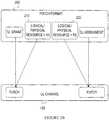
figure 1 there is illustrated an example of a structure of theuplink channel 100 and the format of thePDCCH 200 used to send TPC commands from a base station (NodeB or eNodeB) to a UE or to several UEs. As shown infigure 1 , theuplink channel 100 comprises an uplink traffic channel represented here by a physical uplink shared channel (PUSCH) which occupies a dynamically or statically allocated resource. Theuplink channel 100 also comprises an uplink control channel represented here by a physical uplink control channel (PUCCH) which also occupies a dynamically or statically allocated resource. The allocation (dynamic or static) of the PUSCH and the PUCCH for UEs may be performed by a eNodeB or a radio network controller (RNC) of the communications system. It should be noted that in the LTE architecture the eNodeB may have the functionality of the RNC. Infigure 1 ,resources - According to an embodiment of the present invention, TPC commands included in uplink (UL) grants sent to individual terminals on the PDCCH are applied to the PUSCH, i.e. the uplink traffic channel, whereas TPC commands included in downlink (DL) assignments sent to individual terminals on the PDCCH are applied to the PUCCH i.e. the uplink control channel. A terminal or a UE thus is provided with means to receive the TPC commands and also means to apply the received TPC commands. A TPC command applied to the PUSCH is here denoted TPC-PUSCH and a TPC command applied to the PUCCH is denoted TPC-PUCCH. The TPC commands are transmitted in DL assignments and UL grants on the PDCCH and are here identified by RNTIs (radio network temporary identifiers). The RNTIs may be different thus allowing for independent power control of PUSCH and PUCCH. Therefore, if, in the RRC message(s) received by the UE from the eNodeB, different resources i.e. different RNTIs are used for the PUSCH respectively for the PUCCH then separate TPC commands are applied for the traffic and control channels. If on the other hand the RRC message(s) from the eNodeB to the UE indicates the same RNTIs for the PUSCH and the PUCCH then common TPC commands are applied for the traffic and control channels. Note that since the format of the UL grant and the DL assignment are different, the TPC commands for the PUCCH and PUSCH are separated. Therefore a RNTI received by the UE on the RRC message(s) to identify (e.g. by decoding) a TPC-PDCCH on which the UE should receive TPC commands for power controlling of PUSCH (in the case of UL grant) can be denoted TPC-PUSCH RNTI, and a RNTI received on the RRC message(s) used to identify (e.g. by decoding) a TPC-PDCCH on which the UE should receive TPC commands for power controlling of PUCCH (in DL assignment) can be denoted TPC-PUCCH RNTI. It should also be noted that the UE does not necessarily comprise a single means for applying the received TPC commands. In other words, the UE may comprise one means for applying common TPC commands for the traffic and control channels and one means for applying separate TPC commands for the traffic and control channels.
- Note that in
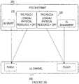
figure 1 only a single UL grant is shown, although several UL grants can be used. Referring tofigure 2A there is illustrated the case where TPC commands for the traffic and control channels occupy the same resource. In this scenario, the RNTI for the TPC-PUSCH (i.e. TPC-PUSCH RNTI) and the RNTI for the TPC-PUCCH (i.e. TPC-PUCCH RNTI) are considered to be the same. This is indicated infigure 2A by using R1 for bothresource 210 andresource 220. - According to another embodiment of the present invention, when the individual logical or
physical resources figure 2B whereresources figure 2B whereresource 210 is represented by R1 andresource 220 is represented by R2. R1 and R2 being different from each other. - The TPC commands can also be sent to a group of terminals in a format of the PDCCH i.e. the TPC-PDCCH. The TPC-PDCCH can be addressed to a group identity representing a logical resource instead of a physical resource. As an example, mobile terminals or UEs can be assigned to groups using higher layer signalling. The RRC signalling is an example of a higher layer signalling. Using the TPC-PDCCH format allows sending TPC commands also preceding uplink transmission(s) not directly preceded by UL grants or DL assignments, e.g. so-called persistent traffic channel allocations, or periodically occurring control channels. In this exemplary embodiment the following steps may be used:
- 1. In the RRC signalling procedure, assigning terminals to group identities where separate identities (but not necessarily distinct) are used for PUSCH and PUCCH.
- 2. In case separate TPC commands for PUSCH and PUCCH are desired, distinct group identities are used for PUSCH and PUCCH.
- 3. If instead common TPC commands for PUSCH and PUCCH are desired, the same group identity is used for PUSCH and PUCCH.
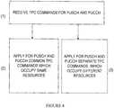
- Referring to
figure 4 , there is illustrated a flowchart of a transmit power control method for use in a UE according to the previously described exemplary embodiments of the present invention. As shown infigure 4 , the main steps of the method comprise: - (1) receiving TPC commands for the traffic (PUSCH) and control (PUCCH) channels respectively; the commands being separately identified by resources, as previously described;
- (2) apply for the traffic and control channels, common TPC commands which occupy the same resources; and
- (3) apply for the traffic and control channels, separate TPC commands which occupy different resources.
When common TPC commands are used, the terminal or UE may be assigned group identity GR1 for PUSCH and for PUCCH. This is illustrated in
Thus, according to the above described embodiment of the present invention, a terminal or a UE could be separately configured with TPC-PDCCH for PUCCH which can, as described earlier, be identified by a certain RNTI and a TPC-PDCCH for PUSCH (which also can be identified by a certain RNTI). It should be noted that the network can configure the same RNTI for the two cases, effectively leading to lower overhead. According to the present invention, the objective of power control may be different for traffic and control channels. As an example, for control channels it is often sufficient to reach a certain minimum signal to noise ratio, whereas for traffic channels, the higher the signal to noise ratio, the better quality is achieved e.g. higher bit rates. Therefore, in such scenario, it is beneficial to use separate TPC commands as described above in according with embodiments of the present invention.
While the invention has been described in terms of several preferred embodiments, it is contemplated that alternatives, modifications, permutations and equivalents thereof will become apparent to those skilled in the art upon reading of the specifications and study of the drawings. It is therefore intended that the following appended claims include such alternatives, modifications, permutations and equivalents as fall within the scope of the present invention.
Claims (11)
- A transmission power control method for use in a user equipment of a telecommunications system comprising at least one base station and at least one user equipment, said system further comprising multiple channels including traffic and control channels each occupying allocated physical or logical resources between said at least one base station and said user equipment, the methodcharacterised in that it comprises;- receiving (1) transmit power control commands for the traffic and control channels respectively, said commands being separately identified by radio network temporary identifiers, RNTIs;- applying (2) for the traffic and control channels, common transmit power control commands when the same RNTIs are used to identify the transmit power control commands for the traffic channel and the control channel; and- applying (3) for the traffic and control channels, separate transmit power control commands when different RNTIs are used to identify the transmit power control commands for the traffic channel and the control channel.
- The method of claim 1, wherein the RNTIs identifying transmit power control commands for the traffic and control channels are configured via an RRC signaling procedure which assigns, to the user equipment, separate TPC group identities for PUSCH and PUCCH.
- The method according to claim 1 or claim 2 further comprising receiving (1) the transmit power control commands on a physical downlink control channel (200), PDCCH, sent from said at least one base station to said user equipment.
- The method according to claim 3 wherein, when the same RNTIs are used to identify the transmit power control commands for the traffic channel and the control channel, applying the common transmit power control commands to a physical uplink shared channel, PUSCH, corresponding to an uplink traffic channel and applying the common transmit power control commands to a physical uplink control channel, PUCCH, corresponding to an uplink control channel.
- The method according to claim 3 wherein, when different RNTIs are used to identify the transmit power control commands for the traffic channel and the control channel, applying separate transmit power control commands to a physical uplink shared channel, PUSCH, corresponding to an uplink traffic channel and to a physical uplink control channel, PUCCH, corresponding to an uplink control channel.
- The method according to any one of claims 1-5 further comprises dynamically or statically allocating physical resources to said transmit power control commands.
- The method according to claim 6 wherein said physical resources correspond to time and/or frequency and/or code.
- A user equipment of a telecommunications system comprising at least one base station and multiple channels including traffic and control channels each occupying allocated physical or logical resources between said at least one base station and said user equipment, the user equipmentcharacterized in that it comprises:- receiving means for receiving transmit power control commands for the traffic and control channels respectively, said commands being separately identified by radio network temporary identifiers, RNTIs (210, 220);- means for applying for the traffic and control channels, common transmit power control commands when the same RNTIs (210, 220) are used to identify the transmit power control commands for the traffic channel and the control channel; and- means for applying for the traffic and control channels, separate transmit power control commands when different RNTIs (210, 220) are used to identify the transmit power control commands for the traffic channel and the control channel.
- The user equipment according to claim 8 wherein said receiving means is configured to receive the transmit power control commands on a physical control channel (200), PDCCH, received from the at least one base station.
- The user equipment according to claim 8 wherein said means for applying is configured to apply, when the same RNTIs (210, 220) are used to identify the transmit power control commands for the traffic channel and the control channel, the common transmit power control commands to a physical uplink shared channel, PUSCH, corresponding to an uplink traffic channel and to further apply the common transmit power control commands to a physical uplink control channel, PUCCH, corresponding to an uplink control channel.
- The user equipment according to claim 8 wherein said means for applying is configured to apply, when different RNTIs (210, 220) are used to identify the transmit power control commands for the traffic channel and the control channel, the separate transmit power control commands to a physical uplink shared channel, PUSCH, corresponding to an uplink traffic channel and to a physical uplink control channel, PUCCH, corresponding to an uplink control channel.
Applications Claiming Priority (3)
| Application Number | Priority Date | Filing Date | Title |
|---|---|---|---|
| US97849707P | 2007-10-09 | 2007-10-09 | |
| PCT/SE2008/050426WO2009048404A1 (en) | 2007-10-09 | 2008-04-16 | An uplink power control method in a telecommunications network system that supports both common and separate tpc commands |
| EP08741916.4AEP2198659B1 (en) | 2007-10-09 | 2008-04-16 | An uplink power control method in a telecommunications network system that supports both common and separate tpc commands |
Related Parent Applications (2)
| Application Number | Title | Priority Date | Filing Date |
|---|---|---|---|
| EP08741916.4ADivision-IntoEP2198659B1 (en) | 2007-10-09 | 2008-04-16 | An uplink power control method in a telecommunications network system that supports both common and separate tpc commands |
| EP08741916.4ADivisionEP2198659B1 (en) | 2007-10-09 | 2008-04-16 | An uplink power control method in a telecommunications network system that supports both common and separate tpc commands |
Publications (2)
| Publication Number | Publication Date |
|---|---|
| EP2911461A1 EP2911461A1 (en) | 2015-08-26 |
| EP2911461B1true EP2911461B1 (en) | 2019-08-14 |
Family
ID=40549399
Family Applications (2)
| Application Number | Title | Priority Date | Filing Date |
|---|---|---|---|
| EP15164207.1AActiveEP2911461B1 (en) | 2007-10-09 | 2008-04-16 | A transmit power control method and an apparatus in a telecommunications network system |
| EP08741916.4AActiveEP2198659B1 (en) | 2007-10-09 | 2008-04-16 | An uplink power control method in a telecommunications network system that supports both common and separate tpc commands |
Family Applications After (1)
| Application Number | Title | Priority Date | Filing Date |
|---|---|---|---|
| EP08741916.4AActiveEP2198659B1 (en) | 2007-10-09 | 2008-04-16 | An uplink power control method in a telecommunications network system that supports both common and separate tpc commands |
Country Status (9)
| Country | Link |
|---|---|
| US (3) | US8594012B2 (en) |
| EP (2) | EP2911461B1 (en) |
| JP (2) | JP4965712B2 (en) |
| KR (1) | KR101546986B1 (en) |
| CN (2) | CN101919293B (en) |
| ES (1) | ES2545581T3 (en) |
| PL (1) | PL2198659T3 (en) |
| RU (2) | RU2459384C2 (en) |
| WO (1) | WO2009048404A1 (en) |
Families Citing this family (39)
| Publication number | Priority date | Publication date | Assignee | Title |
|---|---|---|---|---|
| US7986959B2 (en) | 2007-02-14 | 2011-07-26 | Qualcomm Incorporated | Preamble based uplink power control for LTE |
| US8437792B2 (en)* | 2007-02-14 | 2013-05-07 | Qualcomm Incorporated | Uplink power control for LTE |
| JP4883180B2 (en)* | 2007-07-24 | 2012-02-22 | 富士通株式会社 | Communication system and individual control information transmission / reception method |
| EP2911461B1 (en)* | 2007-10-09 | 2019-08-14 | Telefonaktiebolaget LM Ericsson (publ) | A transmit power control method and an apparatus in a telecommunications network system |
| WO2009058971A2 (en)* | 2007-11-02 | 2009-05-07 | Interdigital Patent Holdings, Inc. | Power control for combined dynamically and persistently scheduled pusch in e-utra |
| KR101459147B1 (en)* | 2008-02-04 | 2014-11-10 | 엘지전자 주식회사 | Method for transmitting transmission power control command in a wireless communication system |
| TWI542241B (en) | 2008-12-03 | 2016-07-11 | 內數位專利控股公司 | Method and apparatus for reporting power headroom |
| US8804585B2 (en)* | 2009-01-09 | 2014-08-12 | Qualcomm Incorporated | Special management connection between base station and relay stations in multihop relay systems for controlling sleep-mode |
| US8982801B2 (en)* | 2009-02-09 | 2015-03-17 | Interdigital Patent Holdings, Inc. | Apparatus and method for uplink power control for a wireless transmitter/receiver unit utilizing multiple carriers |
| US9585108B2 (en) | 2009-05-04 | 2017-02-28 | Qualcomm Incorporated | Method and apparatus for uplink power control in a multicarrier wireless communication system |
| US8665809B2 (en) | 2009-06-15 | 2014-03-04 | Qualcomm Incorporated | Systems and methods for sending power control information |
| WO2010146972A1 (en)* | 2009-06-16 | 2010-12-23 | シャープ株式会社 | Mobile station device, base station device, radio communication method and communication program |
| US9113491B2 (en)* | 2009-07-22 | 2015-08-18 | Qualcomm Incorporated | Uplink control and data transmission in a mixed single and multiple carrier network |
| US8401585B2 (en)* | 2009-09-03 | 2013-03-19 | Telefonaktiebolaget L M Ericsson (Publ) | Method and apparatus for uplink power control in a wireless communication network |
| US9351293B2 (en) | 2009-09-11 | 2016-05-24 | Qualcomm Incorporated | Multiple carrier indication and downlink control information interaction |
| EP2806697B1 (en) | 2009-10-01 | 2021-07-28 | Interdigital Patent Holdings, Inc. | Apparatus and Method for Reporting Power Headroom |
| US9763197B2 (en) | 2009-10-05 | 2017-09-12 | Qualcomm Incorporated | Component carrier power control in multi-carrier wireless network |
| KR101716494B1 (en)* | 2009-11-14 | 2017-03-14 | 삼성전자주식회사 | Apparatus and method to control an uplink transmission power in a communication system |
| CN102111878B (en)* | 2009-12-28 | 2014-12-10 | 中兴通讯股份有限公司 | Resource index coding method and base station in wireless communication system |
| US9124406B2 (en) | 2009-12-29 | 2015-09-01 | Qualcomm Incorporated | Fallback operation for cross-carrier signaling in multi-carrier operation |
| EP2343934A1 (en) | 2010-01-11 | 2011-07-13 | Panasonic Corporation | Transmit power control signaling for communication systems using carrier aggregation |
| US8489100B2 (en)* | 2010-04-13 | 2013-07-16 | Qualcomm Incorporated | Uplink power control in long term evolution networks |
| US9020556B2 (en)* | 2011-01-07 | 2015-04-28 | Interdigital Patent Holdings, Inc. | Methods, apparatus and systems for handling additional power backoff |
| DK2919545T3 (en) | 2011-02-11 | 2016-12-05 | Interdigital Patent Holdings Inc | Device and method for an improved control channel (E-PDCCH). |
| US9007973B2 (en) | 2011-08-15 | 2015-04-14 | Samsung Electronics Co., Ltd. | Methods and systems for dynamic switching, uplink power control and synchronization in wireless networks |
| US10798684B2 (en) | 2011-09-30 | 2020-10-06 | Interdigital Patent Holdings, Inc. | Multipoint transmission in wireless communication |
| KR102402907B1 (en) | 2012-01-27 | 2022-05-30 | 인터디지탈 패튼 홀딩스, 인크 | Systems and/or methods for providing epdcch in a multiple carrier based and/or quasi-collated network |
| US9319997B2 (en)* | 2012-09-18 | 2016-04-19 | Qualcomm Incorporated | Apparatus, method, and system for uplink power control in a heterogeneous wireless communication network |
| US9258781B2 (en)* | 2012-12-03 | 2016-02-09 | Qualcomm Incorporated | Method and apparatus for early termination of an RX chain |
| CN105191445B (en) | 2013-04-03 | 2018-11-27 | 交互数字专利控股公司 | A kind of interference detecting method, device and base station |
| WO2015042838A1 (en)* | 2013-09-26 | 2015-04-02 | Qualcomm Incorporated | Closed-loop power control for lte-tdd eimta |
| CN104869655B (en)* | 2014-02-21 | 2019-07-23 | 株式会社Ntt都科摩 | Uplink resource dispatching method, wireless base station and mobile station |
| JP6019182B1 (en)* | 2015-06-24 | 2016-11-02 | 株式会社Nttドコモ | User terminal, radio base station, and radio communication method |
| CN108605348B (en) | 2016-02-05 | 2022-02-08 | 三星电子株式会社 | Communication method and apparatus in mobile communication system |
| US10687319B2 (en)* | 2016-08-08 | 2020-06-16 | Comcast Cable Communications, Llc | Group power control for a secondary cell |
| JP6656500B2 (en) | 2018-02-08 | 2020-03-04 | 三菱電機株式会社 | Wireless base station, wireless terminal, wireless communication system, transmission power control method, control circuit, and program storage medium |
| WO2019203472A1 (en)* | 2018-04-16 | 2019-10-24 | 엘지전자 주식회사 | Method for transmitting uplink physical channel in wireless communication system and device for supporting same |
| CN109314931B (en)* | 2018-08-10 | 2021-09-03 | 北京小米移动软件有限公司 | Method, device and storage medium for adjusting uplink transmission power of terminal |
| CN114946230B (en)* | 2019-11-15 | 2025-07-29 | 联想(北京)有限公司 | Transmission of power control commands |
Family Cites Families (20)
| Publication number | Priority date | Publication date | Assignee | Title |
|---|---|---|---|---|
| US5732353A (en)* | 1995-04-07 | 1998-03-24 | Ericsson Inc. | Automatic control channel planning in adaptive channel allocation systems |
| US6173162B1 (en) | 1997-06-16 | 2001-01-09 | Telefonaktiebolaget Lm Ericsson (Publ) | Multiple code channel power control in a radio communication system |
| US6831910B1 (en)* | 1998-03-23 | 2004-12-14 | Samsung Electronics Co., Ltd. | Power control device and method for controlling a reverse link common channel in a CDMA communication system |
| US6285667B1 (en)* | 1998-12-02 | 2001-09-04 | Telefonaktiebolaget Lm Ericsson | Page response on existing radio signaling channel |
| CN1964229B (en)* | 2000-10-24 | 2012-09-26 | 北方电讯网络有限公司 | Shared channel structure, systems and methods |
| US7010318B2 (en) | 2001-01-13 | 2006-03-07 | Samsung Electronics Co., Ltd. | Power control apparatus and method for a W-CDMA communication system employing a high-speed downlink packet access scheme |
| DE60201062T2 (en)* | 2001-11-19 | 2004-12-30 | Samsung Electronics Co., Ltd., Suwon | Method and device for controlling the power of the uplink channel in a CDMA communication system |
| US7133688B2 (en)* | 2002-04-05 | 2006-11-07 | Lucent Technologies Inc. | Method for improving uplink control channel efficiency in a wireless communication system |
| JP3574443B2 (en) | 2002-08-20 | 2004-10-06 | 松下電器産業株式会社 | Communication terminal device, base station device, and transmission power control method |
| JP3574446B2 (en)* | 2002-09-19 | 2004-10-06 | 松下電器産業株式会社 | Transmission power control method and base station apparatus |
| KR20040060274A (en)* | 2002-12-30 | 2004-07-06 | 엘지전자 주식회사 | method for controlling a power of the radio links |
| CN100461659C (en) | 2002-12-31 | 2009-02-11 | 中兴通讯股份有限公司 | Power Control Method for Wideband Code Division Multiple Access Mobile Communication System |
| CN100370707C (en) | 2004-11-05 | 2008-02-20 | 华为技术有限公司 | Enhanced uplink dedicated physical channel power control method and device |
| JP4555692B2 (en)* | 2005-01-14 | 2010-10-06 | 富士通株式会社 | Mobile radio communication system and radio communication apparatus |
| JP4637709B2 (en)* | 2005-09-30 | 2011-02-23 | 三菱電機株式会社 | Mobile terminal and mobile communication system |
| CN100531002C (en)* | 2005-11-07 | 2009-08-19 | 华为技术有限公司 | Method for sending information and method and apparatus for receiving information |
| US20070259682A1 (en)* | 2006-05-08 | 2007-11-08 | Jorma Kaikkonen | Enhanced uplink power control with gated uplink of control information |
| US8446849B2 (en)* | 2007-06-20 | 2013-05-21 | Qualcomm Incorporated | Methods and apparatuses for power control |
| TWI519088B (en)* | 2007-08-13 | 2016-01-21 | 內數位科技公司 | Method and device for reducing radio resource overhead of intermittent traffic |
| EP2911461B1 (en)* | 2007-10-09 | 2019-08-14 | Telefonaktiebolaget LM Ericsson (publ) | A transmit power control method and an apparatus in a telecommunications network system |
- 2008
- 2008-04-16EPEP15164207.1Apatent/EP2911461B1/enactiveActive
- 2008-04-16JPJP2010528837Apatent/JP4965712B2/enactiveActive
- 2008-04-16CNCN2008801183360Apatent/CN101919293B/enactiveActive
- 2008-04-16KRKR1020107010189Apatent/KR101546986B1/enactiveActive
- 2008-04-16RURU2010118325/07Apatent/RU2459384C2/enactive
- 2008-04-16ESES08741916.4Tpatent/ES2545581T3/enactiveActive
- 2008-04-16PLPL08741916Tpatent/PL2198659T3/enunknown
- 2008-04-16EPEP08741916.4Apatent/EP2198659B1/enactiveActive
- 2008-04-16WOPCT/SE2008/050426patent/WO2009048404A1/enactiveApplication Filing
- 2008-04-16CNCN201310002261.2Apatent/CN103209471B/enactiveActive
- 2008-04-16USUS12/740,260patent/US8594012B2/enactiveActive
- 2012
- 2012-03-28JPJP2012074151Apatent/JP5580359B2/enactiveActive
- 2012-06-04RURU2012123001/07Apatent/RU2598900C2/enactive
- 2013
- 2013-10-28USUS14/064,548patent/US9532313B2/enactiveActive
- 2016
- 2016-12-27USUS15/391,376patent/US20170111868A1/ennot_activeAbandoned
Non-Patent Citations (1)
| Title |
|---|
| None* |
Also Published As
| Publication number | Publication date |
|---|---|
| RU2012123001A (en) | 2013-12-10 |
| KR101546986B1 (en) | 2015-08-24 |
| EP2198659B1 (en) | 2015-06-03 |
| HK1146184A1 (en) | 2011-05-13 |
| JP5580359B2 (en) | 2014-08-27 |
| US20140128120A1 (en) | 2014-05-08 |
| JP2012147476A (en) | 2012-08-02 |
| US20100238892A1 (en) | 2010-09-23 |
| RU2598900C2 (en) | 2016-10-10 |
| RU2010118325A (en) | 2011-11-20 |
| JP4965712B2 (en) | 2012-07-04 |
| CN101919293A (en) | 2010-12-15 |
| CN101919293B (en) | 2013-12-18 |
| CN103209471A (en) | 2013-07-17 |
| PL2198659T3 (en) | 2015-11-30 |
| EP2198659A4 (en) | 2013-10-23 |
| WO2009048404A1 (en) | 2009-04-16 |
| EP2911461A1 (en) | 2015-08-26 |
| CN103209471B (en) | 2016-01-20 |
| RU2459384C2 (en) | 2012-08-20 |
| US8594012B2 (en) | 2013-11-26 |
| JP2011501502A (en) | 2011-01-06 |
| ES2545581T3 (en) | 2015-09-14 |
| US9532313B2 (en) | 2016-12-27 |
| EP2198659A1 (en) | 2010-06-23 |
| US20170111868A1 (en) | 2017-04-20 |
| KR20100099108A (en) | 2010-09-10 |
Similar Documents
| Publication | Publication Date | Title |
|---|---|---|
| EP2911461B1 (en) | A transmit power control method and an apparatus in a telecommunications network system | |
| RU2722424C2 (en) | Method and apparatus for controlling semi-persistent scheduling | |
| RU2539329C2 (en) | Uplink scheduling support in multi-carrier wireless communication systems | |
| US9419766B2 (en) | Wireless communication terminal device, wireless communication method and integrated circuit for controlling transmission power of sounding reference signal (SRS) | |
| CN101983488B (en) | A method of transmitting CQI report | |
| US20090303939A1 (en) | Shared data channel assigning apparatus and shared data channel assigning method | |
| JP2019537899A (en) | Optimization of search space and sounding reference signal constellation for improved decoding timeline | |
| US20150358914A1 (en) | Bs and ue, and power control methods used in the same | |
| US10560903B2 (en) | Communications device, infrastructure equipment, communications system and methods | |
| CN118435663A (en) | Method and apparatus for reducing base station energy consumption in wireless communication system | |
| JP2025513306A (en) | Method and apparatus for power reduction in wireless communication systems - Patents.com | |
| CN104105186B (en) | A kind of method, apparatus and system for carrying out Power Control | |
| US20250016788A1 (en) | Communications device, infrastructure equipment and methods | |
| CN119277439A (en) | Method and device for user equipment triggering report in wireless communication system | |
| US9763245B2 (en) | System and methods for controlling the usage of a carrier | |
| US20250266861A1 (en) | Bandwidth Part Frequency Hopping for Enhanced Reduced Capability UEs | |
| US11006470B1 (en) | Controlling use of carrier as secondary carrier for carrier-aggregation service | |
| HK1146184B (en) | An uplink power control method in a telecommunications network system that supports both common and separate tpc commands | |
| KR20230152916A (en) | Method and apparatus for base station energy savings in a wireless communication system |
Legal Events
| Date | Code | Title | Description |
|---|---|---|---|
| PUAI | Public reference made under article 153(3) epc to a published international application that has entered the european phase | Free format text:ORIGINAL CODE: 0009012 | |
| AC | Divisional application: reference to earlier application | Ref document number:2198659 Country of ref document:EP Kind code of ref document:P | |
| AK | Designated contracting states | Kind code of ref document:A1 Designated state(s):AT BE BG CH CY CZ DE DK EE ES FI FR GB GR HR HU IE IS IT LI LT LU LV MC MT NL NO PL PT RO SE SI SK TR | |
| 17P | Request for examination filed | Effective date:20160226 | |
| RBV | Designated contracting states (corrected) | Designated state(s):AT BE BG CH CY CZ DE DK EE ES FI FR GB GR HR HU IE IS IT LI LT LU LV MC MT NL NO PL PT RO SE SI SK TR | |
| 17Q | First examination report despatched | Effective date:20160622 | |
| STAA | Information on the status of an ep patent application or granted ep patent | Free format text:STATUS: EXAMINATION IS IN PROGRESS | |
| GRAP | Despatch of communication of intention to grant a patent | Free format text:ORIGINAL CODE: EPIDOSNIGR1 | |
| STAA | Information on the status of an ep patent application or granted ep patent | Free format text:STATUS: GRANT OF PATENT IS INTENDED | |
| RIC1 | Information provided on ipc code assigned before grant | Ipc:H04W 52/54 20090101ALI20190401BHEP Ipc:H04W 52/28 20090101ALN20190401BHEP Ipc:H04B 7/005 20060101ALI20190401BHEP Ipc:H04W 52/14 20090101ALI20190401BHEP Ipc:H04W 52/60 20090101AFI20190401BHEP Ipc:H04W 52/32 20090101ALI20190401BHEP | |
| INTG | Intention to grant announced | Effective date:20190424 | |
| GRAS | Grant fee paid | Free format text:ORIGINAL CODE: EPIDOSNIGR3 | |
| GRAA | (expected) grant | Free format text:ORIGINAL CODE: 0009210 | |
| STAA | Information on the status of an ep patent application or granted ep patent | Free format text:STATUS: THE PATENT HAS BEEN GRANTED | |
| AC | Divisional application: reference to earlier application | Ref document number:2198659 Country of ref document:EP Kind code of ref document:P | |
| AK | Designated contracting states | Kind code of ref document:B1 Designated state(s):AT BE BG CH CY CZ DE DK EE ES FI FR GB GR HR HU IE IS IT LI LT LU LV MC MT NL NO PL PT RO SE SI SK TR | |
| REG | Reference to a national code | Ref country code:GB Ref legal event code:FG4D | |
| REG | Reference to a national code | Ref country code:CH Ref legal event code:EP Ref country code:AT Ref legal event code:REF Ref document number:1168545 Country of ref document:AT Kind code of ref document:T Effective date:20190815 | |
| REG | Reference to a national code | Ref country code:IE Ref legal event code:FG4D | |
| REG | Reference to a national code | Ref country code:DE Ref legal event code:R096 Ref document number:602008060949 Country of ref document:DE | |
| REG | Reference to a national code | Ref country code:NL Ref legal event code:MP Effective date:20190814 | |
| REG | Reference to a national code | Ref country code:LT Ref legal event code:MG4D | |
| PG25 | Lapsed in a contracting state [announced via postgrant information from national office to epo] | Ref country code:NO Free format text:LAPSE BECAUSE OF FAILURE TO SUBMIT A TRANSLATION OF THE DESCRIPTION OR TO PAY THE FEE WITHIN THE PRESCRIBED TIME-LIMIT Effective date:20191114 Ref country code:FI Free format text:LAPSE BECAUSE OF FAILURE TO SUBMIT A TRANSLATION OF THE DESCRIPTION OR TO PAY THE FEE WITHIN THE PRESCRIBED TIME-LIMIT Effective date:20190814 Ref country code:LT Free format text:LAPSE BECAUSE OF FAILURE TO SUBMIT A TRANSLATION OF THE DESCRIPTION OR TO PAY THE FEE WITHIN THE PRESCRIBED TIME-LIMIT Effective date:20190814 Ref country code:NL Free format text:LAPSE BECAUSE OF FAILURE TO SUBMIT A TRANSLATION OF THE DESCRIPTION OR TO PAY THE FEE WITHIN THE PRESCRIBED TIME-LIMIT Effective date:20190814 Ref country code:SE Free format text:LAPSE BECAUSE OF FAILURE TO SUBMIT A TRANSLATION OF THE DESCRIPTION OR TO PAY THE FEE WITHIN THE PRESCRIBED TIME-LIMIT Effective date:20190814 Ref country code:BG Free format text:LAPSE BECAUSE OF FAILURE TO SUBMIT A TRANSLATION OF THE DESCRIPTION OR TO PAY THE FEE WITHIN THE PRESCRIBED TIME-LIMIT Effective date:20191114 Ref country code:PT Free format text:LAPSE BECAUSE OF FAILURE TO SUBMIT A TRANSLATION OF THE DESCRIPTION OR TO PAY THE FEE WITHIN THE PRESCRIBED TIME-LIMIT Effective date:20191216 Ref country code:HR Free format text:LAPSE BECAUSE OF FAILURE TO SUBMIT A TRANSLATION OF THE DESCRIPTION OR TO PAY THE FEE WITHIN THE PRESCRIBED TIME-LIMIT Effective date:20190814 | |
| REG | Reference to a national code | Ref country code:AT Ref legal event code:MK05 Ref document number:1168545 Country of ref document:AT Kind code of ref document:T Effective date:20190814 | |
| PG25 | Lapsed in a contracting state [announced via postgrant information from national office to epo] | Ref country code:GR Free format text:LAPSE BECAUSE OF FAILURE TO SUBMIT A TRANSLATION OF THE DESCRIPTION OR TO PAY THE FEE WITHIN THE PRESCRIBED TIME-LIMIT Effective date:20191115 Ref country code:LV Free format text:LAPSE BECAUSE OF FAILURE TO SUBMIT A TRANSLATION OF THE DESCRIPTION OR TO PAY THE FEE WITHIN THE PRESCRIBED TIME-LIMIT Effective date:20190814 Ref country code:IS Free format text:LAPSE BECAUSE OF FAILURE TO SUBMIT A TRANSLATION OF THE DESCRIPTION OR TO PAY THE FEE WITHIN THE PRESCRIBED TIME-LIMIT Effective date:20191214 Ref country code:ES Free format text:LAPSE BECAUSE OF FAILURE TO SUBMIT A TRANSLATION OF THE DESCRIPTION OR TO PAY THE FEE WITHIN THE PRESCRIBED TIME-LIMIT Effective date:20190814 | |
| PG25 | Lapsed in a contracting state [announced via postgrant information from national office to epo] | Ref country code:RO Free format text:LAPSE BECAUSE OF FAILURE TO SUBMIT A TRANSLATION OF THE DESCRIPTION OR TO PAY THE FEE WITHIN THE PRESCRIBED TIME-LIMIT Effective date:20190814 Ref country code:AT Free format text:LAPSE BECAUSE OF FAILURE TO SUBMIT A TRANSLATION OF THE DESCRIPTION OR TO PAY THE FEE WITHIN THE PRESCRIBED TIME-LIMIT Effective date:20190814 Ref country code:PL Free format text:LAPSE BECAUSE OF FAILURE TO SUBMIT A TRANSLATION OF THE DESCRIPTION OR TO PAY THE FEE WITHIN THE PRESCRIBED TIME-LIMIT Effective date:20190814 Ref country code:DK Free format text:LAPSE BECAUSE OF FAILURE TO SUBMIT A TRANSLATION OF THE DESCRIPTION OR TO PAY THE FEE WITHIN THE PRESCRIBED TIME-LIMIT Effective date:20190814 Ref country code:EE Free format text:LAPSE BECAUSE OF FAILURE TO SUBMIT A TRANSLATION OF THE DESCRIPTION OR TO PAY THE FEE WITHIN THE PRESCRIBED TIME-LIMIT Effective date:20190814 | |
| PG25 | Lapsed in a contracting state [announced via postgrant information from national office to epo] | Ref country code:CZ Free format text:LAPSE BECAUSE OF FAILURE TO SUBMIT A TRANSLATION OF THE DESCRIPTION OR TO PAY THE FEE WITHIN THE PRESCRIBED TIME-LIMIT Effective date:20190814 Ref country code:SK Free format text:LAPSE BECAUSE OF FAILURE TO SUBMIT A TRANSLATION OF THE DESCRIPTION OR TO PAY THE FEE WITHIN THE PRESCRIBED TIME-LIMIT Effective date:20190814 Ref country code:IS Free format text:LAPSE BECAUSE OF FAILURE TO SUBMIT A TRANSLATION OF THE DESCRIPTION OR TO PAY THE FEE WITHIN THE PRESCRIBED TIME-LIMIT Effective date:20200224 | |
| REG | Reference to a national code | Ref country code:DE Ref legal event code:R097 Ref document number:602008060949 Country of ref document:DE | |
| PLBE | No opposition filed within time limit | Free format text:ORIGINAL CODE: 0009261 | |
| STAA | Information on the status of an ep patent application or granted ep patent | Free format text:STATUS: NO OPPOSITION FILED WITHIN TIME LIMIT | |
| PG2D | Information on lapse in contracting state deleted | Ref country code:IS | |
| 26N | No opposition filed | Effective date:20200603 | |
| PG25 | Lapsed in a contracting state [announced via postgrant information from national office to epo] | Ref country code:SI Free format text:LAPSE BECAUSE OF FAILURE TO SUBMIT A TRANSLATION OF THE DESCRIPTION OR TO PAY THE FEE WITHIN THE PRESCRIBED TIME-LIMIT Effective date:20190814 | |
| PG25 | Lapsed in a contracting state [announced via postgrant information from national office to epo] | Ref country code:MC Free format text:LAPSE BECAUSE OF FAILURE TO SUBMIT A TRANSLATION OF THE DESCRIPTION OR TO PAY THE FEE WITHIN THE PRESCRIBED TIME-LIMIT Effective date:20190814 | |
| PG25 | Lapsed in a contracting state [announced via postgrant information from national office to epo] | Ref country code:LU Free format text:LAPSE BECAUSE OF NON-PAYMENT OF DUE FEES Effective date:20200416 | |
| REG | Reference to a national code | Ref country code:BE Ref legal event code:MM Effective date:20200430 | |
| PG25 | Lapsed in a contracting state [announced via postgrant information from national office to epo] | Ref country code:BE Free format text:LAPSE BECAUSE OF NON-PAYMENT OF DUE FEES Effective date:20200430 | |
| PG25 | Lapsed in a contracting state [announced via postgrant information from national office to epo] | Ref country code:IE Free format text:LAPSE BECAUSE OF NON-PAYMENT OF DUE FEES Effective date:20200416 | |
| PG25 | Lapsed in a contracting state [announced via postgrant information from national office to epo] | Ref country code:MT Free format text:LAPSE BECAUSE OF FAILURE TO SUBMIT A TRANSLATION OF THE DESCRIPTION OR TO PAY THE FEE WITHIN THE PRESCRIBED TIME-LIMIT Effective date:20190814 Ref country code:CY Free format text:LAPSE BECAUSE OF FAILURE TO SUBMIT A TRANSLATION OF THE DESCRIPTION OR TO PAY THE FEE WITHIN THE PRESCRIBED TIME-LIMIT Effective date:20190814 | |
| PGFP | Annual fee paid to national office [announced via postgrant information from national office to epo] | Ref country code:DE Payment date:20250429 Year of fee payment:18 | |
| PGFP | Annual fee paid to national office [announced via postgrant information from national office to epo] | Ref country code:GB Payment date:20250428 Year of fee payment:18 | |
| PGFP | Annual fee paid to national office [announced via postgrant information from national office to epo] | Ref country code:IT Payment date:20250422 Year of fee payment:18 | |
| PGFP | Annual fee paid to national office [announced via postgrant information from national office to epo] | Ref country code:FR Payment date:20250425 Year of fee payment:18 | |
| PGFP | Annual fee paid to national office [announced via postgrant information from national office to epo] | Ref country code:CH Payment date:20250501 Year of fee payment:18 | |
| PGFP | Annual fee paid to national office [announced via postgrant information from national office to epo] | Ref country code:TR Payment date:20250416 Year of fee payment:18 |