EP2908970B1 - Metal alloy injection molding protrusions - Google Patents
Metal alloy injection molding protrusionsDownload PDFInfo
- Publication number
- EP2908970B1 EP2908970B1EP12886770.2AEP12886770AEP2908970B1EP 2908970 B1EP2908970 B1EP 2908970B1EP 12886770 AEP12886770 AEP 12886770AEP 2908970 B1EP2908970 B1EP 2908970B1
- Authority
- EP
- European Patent Office
- Prior art keywords
- metal alloy
- article
- mold
- cavity
- feature
- Prior art date
- Legal status (The legal status is an assumption and is not a legal conclusion. Google has not performed a legal analysis and makes no representation as to the accuracy of the status listed.)
- Active
Links
- 229910001092metal group alloyInorganic materials0.000titleclaimsdescription106
- 238000001746injection mouldingMethods0.000titledescription19
- 238000000034methodMethods0.000claimsdescription54
- 238000000465mouldingMethods0.000claimsdescription19
- 230000000694effectsEffects0.000claimsdescription13
- FYYHWMGAXLPEAU-UHFFFAOYSA-NMagnesiumChemical compound[Mg]FYYHWMGAXLPEAU-UHFFFAOYSA-N0.000claimsdescription8
- 229910052749magnesiumInorganic materials0.000claimsdescription8
- 239000011777magnesiumSubstances0.000claimsdescription8
- 238000002347injectionMethods0.000description33
- 239000007924injectionSubstances0.000description33
- 238000007796conventional methodMethods0.000description10
- 238000001816coolingMethods0.000description9
- 239000000463materialSubstances0.000description9
- 230000006835compressionEffects0.000description7
- 238000007906compressionMethods0.000description7
- 230000008602contractionEffects0.000description7
- 238000009826distributionMethods0.000description7
- 230000015572biosynthetic processEffects0.000description6
- 239000004033plasticSubstances0.000description6
- 229920003023plasticPolymers0.000description6
- 238000010586diagramMethods0.000description5
- 239000007788liquidSubstances0.000description3
- 238000004519manufacturing processMethods0.000description3
- 238000010438heat treatmentMethods0.000description2
- 238000003754machiningMethods0.000description2
- 239000011347resinSubstances0.000description2
- 229920005989resinPolymers0.000description2
- OYPRJOBELJOOCE-UHFFFAOYSA-NCalciumChemical compound[Ca]OYPRJOBELJOOCE-UHFFFAOYSA-N0.000description1
- 229910000861Mg alloyInorganic materials0.000description1
- HCHKCACWOHOZIP-UHFFFAOYSA-NZincChemical compound[Zn]HCHKCACWOHOZIP-UHFFFAOYSA-N0.000description1
- 230000002411adverseEffects0.000description1
- 229910052782aluminiumInorganic materials0.000description1
- XAGFODPZIPBFFR-UHFFFAOYSA-NaluminiumChemical compound[Al]XAGFODPZIPBFFR-UHFFFAOYSA-N0.000description1
- 229910052791calciumInorganic materials0.000description1
- 239000011575calciumSubstances0.000description1
- 238000005520cutting processMethods0.000description1
- 239000012535impuritySubstances0.000description1
- WPBNNNQJVZRUHP-UHFFFAOYSA-Lmanganese(2+);methyl n-[[2-(methoxycarbonylcarbamothioylamino)phenyl]carbamothioyl]carbamate;n-[2-(sulfidocarbothioylamino)ethyl]carbamodithioateChemical compound[Mn+2].[S-]C(=S)NCCNC([S-])=S.COC(=O)NC(=S)NC1=CC=CC=C1NC(=S)NC(=O)OCWPBNNNQJVZRUHP-UHFFFAOYSA-L0.000description1
- 229910052751metalInorganic materials0.000description1
- 239000002184metalSubstances0.000description1
- 238000003825pressingMethods0.000description1
- 230000001737promoting effectEffects0.000description1
- 238000003860storageMethods0.000description1
- 229920001169thermoplasticPolymers0.000description1
- 229920001187thermosetting polymerPolymers0.000description1
- 239000004416thermosoftening plasticSubstances0.000description1
- 239000011701zincSubstances0.000description1
- 229910052725zincInorganic materials0.000description1
Images


Classifications
- B—PERFORMING OPERATIONS; TRANSPORTING
- B22—CASTING; POWDER METALLURGY
- B22C—FOUNDRY MOULDING
- B22C9/00—Moulds or cores; Moulding processes
- B22C9/06—Permanent moulds for shaped castings
- B—PERFORMING OPERATIONS; TRANSPORTING
- B22—CASTING; POWDER METALLURGY
- B22D—CASTING OF METALS; CASTING OF OTHER SUBSTANCES BY THE SAME PROCESSES OR DEVICES
- B22D17/00—Pressure die casting or injection die casting, i.e. casting in which the metal is forced into a mould under high pressure
- B22D17/08—Cold chamber machines, i.e. with unheated press chamber into which molten metal is ladled
- B—PERFORMING OPERATIONS; TRANSPORTING
- B22—CASTING; POWDER METALLURGY
- B22D—CASTING OF METALS; CASTING OF OTHER SUBSTANCES BY THE SAME PROCESSES OR DEVICES
- B22D17/00—Pressure die casting or injection die casting, i.e. casting in which the metal is forced into a mould under high pressure
- B22D17/14—Machines with evacuated die cavity
- B—PERFORMING OPERATIONS; TRANSPORTING
- B22—CASTING; POWDER METALLURGY
- B22D—CASTING OF METALS; CASTING OF OTHER SUBSTANCES BY THE SAME PROCESSES OR DEVICES
- B22D17/00—Pressure die casting or injection die casting, i.e. casting in which the metal is forced into a mould under high pressure
- B22D17/20—Accessories: Details
- B22D17/22—Dies; Die plates; Die supports; Cooling equipment for dies; Accessories for loosening and ejecting castings from dies
- Y—GENERAL TAGGING OF NEW TECHNOLOGICAL DEVELOPMENTS; GENERAL TAGGING OF CROSS-SECTIONAL TECHNOLOGIES SPANNING OVER SEVERAL SECTIONS OF THE IPC; TECHNICAL SUBJECTS COVERED BY FORMER USPC CROSS-REFERENCE ART COLLECTIONS [XRACs] AND DIGESTS
- Y10—TECHNICAL SUBJECTS COVERED BY FORMER USPC
- Y10T—TECHNICAL SUBJECTS COVERED BY FORMER US CLASSIFICATION
- Y10T428/00—Stock material or miscellaneous articles
- Y10T428/12—All metal or with adjacent metals
- Y10T428/12389—All metal or with adjacent metals having variation in thickness
Definitions
- US 5,340,528discloses an injection molding die that includes a fixed half die and a movable half die which has a core surface and which is provided with ejector pins.
- the ejector pinsare held with their extremities retracted from the core surface to form recesses corresponding to compression allowances.
- the ejector pinsare advanced toward the cavity to compress the compression allowances after a molten resin has been injected into the injection molding die in a manner which fills the cavity and the recesses.
- the compression with the ejector pinsrenders the pressure distribution in the cavity uniform.
- US 2008/0185747describes a compression pin that is placed at a cavity surface in an injection mold by the pressing force of a biasing member, and that is moved rearward by the pressure of filled resin so as to form a compression boss. After the completion of filling, the compression boss is compressed by the compression pin.
- CN 1 782 112relates to the production of a magnesium alloy with improved fluidity by incorporating certain amounts of aluminum, zinc, calcium, and manganese, along with the inevitable impurities.
- Metal alloy injection molding techniquesare described.
- techniquesare described that may be utilized to support injection molding of a metal alloy, such as a metal alloy that is comprised primarily of magnesium. These techniques include configuration of runners used to fill a cavity of a mold such that a rate of flow is not slowed by the runners, such as to match an overall size of branches of a runner to a runner from which they branch.
- injection pressure and vacuum pressuremay be arranged to encourage flow through an entirety of a cavity that is used to form an article.
- the vacuum pressuremay be used to bias flow toward portions of the cavity that otherwise may be difficult to fill. This biasing may also be performed using overflows to encourage flow toward these areas, such as areas of the cavity that are feature rich and thus may be difficult to fill using conventional techniques.
- protrusionsare formed to counteract effects of thermal expansion on an article to be molded.
- the protrusionsare sized to counteract shrinkage caused by a thickness of a feature after the metal alloy cools in the mold. In this way, the protrusions may be used to form a substantially flat surface even though features may be disposed on an opposing side of the surface.
- a radiusmay be employed by features to encourage fill and reduce voids in an article.
- a relatively thin articlee.g., less than one millimeter
- sharp cornersmay cause voids at the corners due to turbulence and other factors encountered in the injection of the metal alloy into a mold.
- a radiusmay be utilized that is based at least in part on a thickness of the article to encourage flow and reduce voids.
- Example proceduresare then described which may be performed in the example environment as well as other environments. Consequently, performance of the example procedures is not limited to the example environment and the example environment is not limited to performance of the example procedures.It should be readily apparent that these technique may be combined, separated, and so on.
- FIG. 1is an illustration of an environment in an example implementation showing a system 100 that is operable to employ injection mold techniques described herein.
- the illustrated environmentincludes a computing device 102 that is communicatively coupled to an injection device 104 and a molding device 106. Although illustrated separately, the functionality represented by these apparatus may be combined, further divided, and so on.
- the computing device 102is illustrated as including an injection molding control module 108, which is representative of functionality to control operation of the injection device 104 and molding device 106.
- the injection molding control module 108may utilize one or more instructions 110 stored on a computer-readable storage media 112. The one or more instructions 110 may then be used to control operation of the injection device 104 and molding device 106 to form an article using injection molding.
- the injection device 104may include an injection control module 116 to control heating and injection of a metal alloy 118 that is to be injected into a mold 120 of the molding device 106.
- Injection device 104may include a heating element to heat and liquefy the metal alloy 118, such as to melt a metal alloy comprised primarily of magnesium to approximately six hundred and fifty degrees Celsius.
- the injection device 104may then employ an injector (e.g., a plunger or screw type injector) to inject the metal alloy 118 in liquid form under pressure into the mold 120 of the molding device, such as at approximately forty mPaalthough other pressures are also contemplated.
- an injectore.g., a plunger or screw type injector
- the molding device 106is illustrated as including a mold control module 122, which is representative of functionality to control operation of the mold 120.
- the mold 120may a plurality of mold portions 124, 126.
- the mold portions 124, 126when disposed proximal to each other form a cavity 128 that defines the article 114 to be molded.
- the mold portions 124, 126may then be moved apart to remove the article 114 from the mold 120.
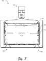
- FIG. 2depicts an example implementation 200 in which features of an article molded using the system 100 of FIG. 1 is shown.
- the article 114is configured to form part of a housing for a computing device in a hand held form factor, e.g., tablet, mobile phone, game device, music device, and so on.
- a hand held form factore.g., tablet, mobile phone, game device, music device, and so on.
- the article 114 in this instanceincludes portions that define a wall 202 of the article 114.
- Features 204, 206are also included that extend away from the wall 202 and thus have a thickness that is greater than the wall. Additionally, the features 204, 206 may have a width that is considered relatively thin in comparison with this thickness. Accordingly, in form factors in which the wall is also considered thin (e.g., less than one millimeter) it may be difficult to get the metal alloy 118 to flow into these features using conventional techniques.
- a cavity 128 defined by the mold portions 124, 126may be shaped to form the wall 202 and the features 204, 206.
- a flow of the metal alloy 118 into the cavity 128 at relatively thin thicknessmay cause the metal alloy 114 to cool before filling the cavity 128 and thus may be leave voids in the cavity 128 between the metal alloy 114 and surfaces of the cavity 128. These voids may consequently have an adverse effect on the article 114 being molded. Accordingly, techniques may be employed to reduce and even eliminate formation of the voids, an example of which is described in the following discussion and corresponding figure.
- FIG. 4depicts a system 400 in an example implementation in which an injection distribution device 402 is used to physically couple an outflow of the injected metal alloy from the injection device 104 to a mold 120 of the molding device 106.
- Pressure used to inject the metal alloy 118 to form the article 114may set to encourage a uniform fill of the cavity 128 of the mold 120.
- a pressuremay be employed by the injection device 104 that is sufficient to form an alpha layer (e.g., skin) on an outer surface of the metal alloy 118 as it flows through the mold 120.
- the alpha layermay have a higher density at a surface than in the "middle" of the metal alloy 118 when flowing into the mold 120. This may be formed based at least in part using relatively high pressures (such as around 40mega Pascals) such that the skin is pressed against a surface of the mold 120 thereby reducing formation of voids.
- relatively high pressuressuch as around 40mega Pascals
- an injection distribution device 402may be configured to encourage this flow from the injection device 104 into the mold 120.
- the injection device 402 in this exampleincludes a runner 404 and a plurality of sub-runners 406, 408, 410.
- the sub-runners 406-410are used to distribute the metal alloy 118 into different portions of the mold 120 to promote a generally uniform application of the metal alloy 118.
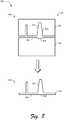
- FIG. 5depicts an example implementation 500 showing comparison of respect cross sections 412, 414 of the runner 404 and the plurality of sub-runners 406-410.
- the cross section 412 of the runner 404is approximately equal to or less than a cross section 414 overall of the plurality of sub-runners 406-408. This may be performed by varying a diameter (e.g.,including height and/or width) such that flow is not reduced as the metal alloy 118 passes through the injection distribution device 104.
- a cavity under conventional techniquesit may be difficult using conventional techniques to fill a cavity under conventional techniques to form a part of a housing of a computing device that has walls having a thickness of approximately 0.65 millimeters and width and length of greater than 100 millimeters and one hundred and fifty millimeters, respectively (e.g., approximately 190 millimeters by 240 millimeters for a tablet).
- the metal alloy 118may cool and harden, especially at those thicknesses and lengths due to the large amount of surface area in comparison with thicker and/or shorter articles.
- the techniques described hereinmay be employed to form such an article.
- a vacuum device 602is employed to bias a flow of the metal alloy 118 through the cavity 128 to form the article 114.
- the vacuum device 602may be configured to form negative pressure within the cavity 128 of the mold 120.
- the negative pressuree.g., 0.4 bar
- the negative pressuremay include a partial vacuum formed to remove air from the cavity 218, thereby reducing a chance of formation of air pockets as the cavity 128 is filled with the metal alloy 118.
- FIG. 7depicts a system 700 in an example implementation in which a mold 120 includes one or more overflows 702, 704 to bias a flow of metal alloy 118 through a mold 120.
- characteristics of the article 114 to be moldedmay cause complications, such as due to relative thinness (e.g., less than one millimeter), length of article (e.g., 100 millimeters or over), shape of article 114 (e.g., to reach corners on the opposing side of the cavity 128 from the injection device 104), features and feature density, and so on. These complications may make it difficult to get the metal alloy 118 to flow to particular portions of the mold 120, such as due to cooling and so forth.
- overflows 702, 704are utilized to bias flow of the metal alloy 118 towards the overflows 702, 704.
- the overflows 702, 704, for instance,may bias flow toward the corners of the cavity 128 in the illustrated example. In this way, a portion of the cavity 128 that may be otherwise difficult to fill may be formed using the metal alloy 118 without introducing voids.
- Other examplesare also contemplated, such as to position the overflows 702, 704 based on feature density of corresponding portions of the cavity 128 of the mold 120.
- materiale.g., the metal alloy 118
- disposed within the overflows 702, 704may be removed to form the article 114, such as by a machining operation.
- the overflows 702, 704may be utilized to counteract a "cold material" condition in which the material (e.g., the metal alloy 118) does not fill the cavity 128 completely, thus forming voids such as pinholes.
- the colder materialfor instance, may exit the overflows 702, 704 thus promoting contact of hotter material (e.g., metal alloy 118 still in substantially liquid form) to form the article 114. This may also aide a microstructure of the article 114 due to the lack of imperfections as could be encountered otherwise.
- the moldalso defines a protrusion for the article aligned as substantially opposing the feature, the protrusion being sized such that upon solidifying of the metal alloy that forms the article, the protrusion reduces an effect of thermal expansion on a portion of the article that is aligned as substantially opposing the feature (block 1202).
- the protrusionfor instance, may be formed as an indention in part of the cavity 128 of the mold 120.
- FIG. 14depicts a procedure 1400 in an example implementation in which a radius is employed to limit formation of voids of the article.
- a metal alloyis injected into a mold having a plurality of molding portions that define a cavity that corresponds to an article to be molded including walls with a thickness of less than one millimeter with one or more features disposed thereon having edges with a radius of at least 0.6 millimeter (block 1402).
- metal alloysmay introduce complications not encountered using plastics, such as quicker cooling and resistance to flow through a mold 120, especially for articles having a thickness of under one millimeter.
- the radiusmay be employed to reduce voids caused by sharp edges.
- At least a portion of the radius of the edgeis machined to define the feature of the article after removal of the metal alloy from the cavity (block 1404). In this way, a sharp edge may be provided on the device yet a likelihood of voids reduced. A variety of other examples are also contemplated as previously described in relation to FIG. 9 .
Landscapes
- Engineering & Computer Science (AREA)
- Mechanical Engineering (AREA)
- Moulds For Moulding Plastics Or The Like (AREA)
- Injection Moulding Of Plastics Or The Like (AREA)
Description
- Injection molding is a manufacturing process that is conventionally utilized to form articles from plastic. This may include use of thermoplastic and thermosetting plastic materials to form an article, such as a toy, car parts, and so on.
- Techniques were subsequently developed to use injection molding for materials other than plastic, such as metal alloys. However, characteristics of the metal alloys could limit use of conventional injection molding techniques to small articles such as watch parts due to complications caused by these characteristics, such as to flow, thermal expansion, and so on.
US 5,340,528 discloses an injection molding die that includes a fixed half die and a movable half die which has a core surface and which is provided with ejector pins. The ejector pins are held with their extremities retracted from the core surface to form recesses corresponding to compression allowances. The ejector pins are advanced toward the cavity to compress the compression allowances after a molten resin has been injected into the injection molding die in a manner which fills the cavity and the recesses. The compression with the ejector pins renders the pressure distribution in the cavity uniform.US 2008/0185747 describes a compression pin that is placed at a cavity surface in an injection mold by the pressing force of a biasing member, and that is moved rearward by the pressure of filled resin so as to form a compression boss. After the completion of filling, the compression boss is compressed by the compression pin.CN 1 782 112 relates to the production of a magnesium alloy with improved fluidity by incorporating certain amounts of aluminum, zinc, calcium, and manganese, along with the inevitable impurities.- The invention provides methods as claimed hereinafter, while metal alloy injection molding techniques are described herein that include adjustment of injection pressure, configuration of runners, and/or use of vacuum pressure, and so on to encourage flow of the metal alloy through a mold. Techniques are also described that utilize protrusions to counteract thermal expansion and subsequent contraction of the metal alloy upon cooling. Further, techniques are described in which a radius of edges of a feature is configured to encourage flow and reduce voids. A variety of other techniques are also described herein.
- The detailed description is described with reference to the accompanying figures. In the figures, the left-most digit(s) of a reference number identifies the figure in which the reference number first appears. The use of the same reference numbers in different instances in the description and the figures may indicate similar or identical items. Entities represented in the figures may be indicative of one or more entities and thus reference may be made interchangeably to single or plural forms of the entities in the discussion.
FIG. 1 is an illustration of an environment in an example implementation that is operable to employ injection molding techniques described herein.FIG. 2 depicts an example implementation in which features of an article molded using a system ofFIG. 1 is shown.FIG. 3 depicts an example implementation in which a cavity defined by mold portions may be shaped to form a wall and features ofFIG. 2 .FIG. 4 depicts a system in an example implementation in which an injection distribution device is used to physically couple an outflow of injected metal alloy from an injection device to a mold of a molding device.FIG. 5 depicts an example implementation showing comparison of respective cross sections of the runner and the plurality of sub-runners ofFIG. 4 .FIG. 6 depicts a system in an example implementation in which a vacuum device is employed to create negative pressure inside a cavity of the mold to promote flow of the metal alloy.FIG. 7 depicts a system in an example implementation in which a mold includes one or more overflows to bias a flow of metal alloy through a mold.FIG. 8 depicts an example implementation in which a protrusion is utilized to reduce an effect of thermal expansion caused by varying degrees of thickness of an article to be molded.FIG. 9 depicts an example implementation in which a mold is employed that includes edges configured to reduce voids.FIG. 10 is a flow diagram depicting a procedure in an example implementation in which an article is injected molded using a mold that employs overflows.FIG. 11 is a flow diagram depicting a procedure in an example implementation in which a mold is formed that employs overflows.FIG. 12 is a flow diagram depicting a procedure in an example implementation in which a protrusion is formed to at least partially counteract thermal expansion of the metal alloy and subsequent contraction caused by cooling of the metal alloy.FIG. 13 is a flow diagram depicting a procedure in an example implementation in which a mold is formed that is configured to form a protrusion on an article to counteract an effect of thermal expansion.FIG. 14 is a flow diagram depicting a procedure in an example implementation in which a radius is employed to limit formation of voids of the article.- Conventional injection molding techniques could encounter complications when utilized for a metal alloy. For example, characteristics of the metal alloy may make these conventional techniques unsuitable to make articles over a relatively short length (e.g., larger than a watch part), that are relatively thin (e.g., less than one millimeter), and so on due to such characteristics of thermal expansion, cooling in a mold, and so forth.
- Metal alloy injection molding techniques are described. In one or more implementations, techniques are described that may be utilized to support injection molding of a metal alloy, such as a metal alloy that is comprised primarily of magnesium. These techniques include configuration of runners used to fill a cavity of a mold such that a rate of flow is not slowed by the runners, such as to match an overall size of branches of a runner to a runner from which they branch.
- In another example, injection pressure and vacuum pressure may be arranged to encourage flow through an entirety of a cavity that is used to form an article. The vacuum pressure, for instance, may be used to bias flow toward portions of the cavity that otherwise may be difficult to fill. This biasing may also be performed using overflows to encourage flow toward these areas, such as areas of the cavity that are feature rich and thus may be difficult to fill using conventional techniques.
- In a further example, protrusions are formed to counteract effects of thermal expansion on an article to be molded. The protrusions are sized to counteract shrinkage caused by a thickness of a feature after the metal alloy cools in the mold. In this way, the protrusions may be used to form a substantially flat surface even though features may be disposed on an opposing side of the surface.
- In yet another example, a radius may be employed by features to encourage fill and reduce voids in an article. In a relatively thin article (e.g., less than one millimeter), for instance, sharp corners may cause voids at the corners due to turbulence and other factors encountered in the injection of the metal alloy into a mold. Accordingly, a radius may be utilized that is based at least in part on a thickness of the article to encourage flow and reduce voids. A variety of other examples are also contemplated, further discussion of which may be found in relation to the following sections.
- In the following discussion, an example environment is first described that may employ the techniques described herein. Example procedures are then described which may be performed in the example environment as well as other environments. Consequently, performance of the example procedures is not limited to the example environment and the example environment is not limited to performance of the example procedures.It should be readily apparent that these technique may be combined, separated, and so on.
FIG. 1 is an illustration of an environment in an example implementation showing asystem 100 that is operable to employ injection mold techniques described herein. The illustrated environment includes acomputing device 102 that is communicatively coupled to aninjection device 104 and amolding device 106. Although illustrated separately, the functionality represented by these apparatus may be combined, further divided, and so on.- The
computing device 102 is illustrated as including an injectionmolding control module 108, which is representative of functionality to control operation of theinjection device 104 andmolding device 106. The injectionmolding control module 108, for instance, may utilize one ormore instructions 110 stored on a computer-readable storage media 112. The one ormore instructions 110 may then be used to control operation of theinjection device 104 andmolding device 106 to form an article using injection molding. - The
injection device 104, for instance, may include an injection control module 116 to control heating and injection of ametal alloy 118 that is to be injected into amold 120 of themolding device 106.Injection device 104, for instance, may include a heating element to heat and liquefy themetal alloy 118, such as to melt a metal alloy comprised primarily of magnesium to approximately six hundred and fifty degrees Celsius. Theinjection device 104 may then employ an injector (e.g., a plunger or screw type injector) to inject themetal alloy 118 in liquid form under pressure into themold 120 of the molding device, such as at approximately forty mPaalthough other pressures are also contemplated. - The
molding device 106 is illustrated as including amold control module 122, which is representative of functionality to control operation of themold 120. Themold 120, for instance, may a plurality ofmold portions mold portions cavity 128 that defines thearticle 114 to be molded. Themold portions article 114 from themold 120. - As previously described, conventional techniques may encounter complications when used to mold an
article 114 using a metal alloy118. For example, anarticle 114 having walls with a thickness of less than one millimeter may make it difficult to fill an entirety of thecavity 128 to form thearticle 114 as themetal alloy 118 may not readily flow through thecavity 128 before cooling. This may be further complicated when thearticle 114 includes a variety of different features that are to be formed on part of the wall, as further described as follows and shown in a corresponding figure. FIG. 2 depicts anexample implementation 200 in which features of an article molded using thesystem 100 ofFIG. 1 is shown. In this example, thearticle 114 is configured to form part of a housing for a computing device in a hand held form factor, e.g., tablet, mobile phone, game device, music device, and so on.- The
article 114 in this instance includes portions that define awall 202 of thearticle 114.Features wall 202 and thus have a thickness that is greater than the wall. Additionally, thefeatures metal alloy 118 to flow into these features using conventional techniques. - As shown in the
example implementation 300 ofFIG. 3 , for instance, acavity 128 defined by themold portions wall 202 and thefeatures metal alloy 118 into thecavity 128 at relatively thin thickness may cause themetal alloy 114 to cool before filling thecavity 128 and thus may be leave voids in thecavity 128 between themetal alloy 114 and surfaces of thecavity 128. These voids may consequently have an adverse effect on thearticle 114 being molded. Accordingly, techniques may be employed to reduce and even eliminate formation of the voids, an example of which is described in the following discussion and corresponding figure. FIG. 4 depicts asystem 400 in an example implementation in which aninjection distribution device 402 is used to physically couple an outflow of the injected metal alloy from theinjection device 104 to amold 120 of themolding device 106. Pressure used to inject themetal alloy 118 to form thearticle 114 may set to encourage a uniform fill of thecavity 128 of themold 120.- For example, a pressure may be employed by the
injection device 104 that is sufficient to form an alpha layer (e.g., skin) on an outer surface of themetal alloy 118 as it flows through themold 120. The alpha layer, for instance, may have a higher density at a surface than in the "middle" of themetal alloy 118 when flowing into themold 120. This may be formed based at least in part using relatively high pressures (such as around 40mega Pascals) such that the skin is pressed against a surface of themold 120 thereby reducing formation of voids. Thus, the thicker the alpha layer the less chance of forming voids in themold 120. - Additionally, an
injection distribution device 402 may be configured to encourage this flow from theinjection device 104 into themold 120. Theinjection device 402 in this example includes arunner 404 and a plurality ofsub-runners metal alloy 118 into different portions of themold 120 to promote a generally uniform application of themetal alloy 118. - However, conventional injection distribution devices were often configured such that a flow of the
metal alloy 118 or other material was hindered by the branches of the device. The branches formed by sub-runners of convention devices, for instance, may be sized such as to cause an approximate forty percent flowrestriction between a runner and the sub-runners that were configured to receive themetal alloy 118. Thus, this flow restriction could cause cooling of themetal alloy 118 as well as counteract functionality supported through use of particular pressures (e.g., about 40 mega Pascals) used to form alpha layers. - Accordingly, the
injection distribution device 402 may be configured such that a decrease in flow of themetal alloy 118 through the device is not experienced. For example, a size of across section 412 taken of therunner 404 may be approximated by an overall size of across section 414 taken of the plurality ofsub-runners FIG. 5 depicts anexample implementation 500 showing comparison ofrespect cross sections runner 404 and the plurality of sub-runners 406-410. Thecross section 412 of therunner 404 is approximately equal to or less than across section 414 overall of the plurality of sub-runners 406-408. This may be performed by varying a diameter (e.g.,including height and/or width) such that flow is not reduced as themetal alloy 118 passes through theinjection distribution device 104.- For example, the
runner 404 may be sized to coincide with an injection port of theinjection device 104 and the plurality of sub-runners 406-410 may get progressively shorter and wider to coincide with a form factor of thecavity 128 of themold 120. Additionally, although asingle runner 404 and three sub-runners 406-410 are shown it should be readily apparent that different numbers and combinations are also contemplated. Additional techniques may also be employed to reduce a likelihood of voids in the article, another example of which is described as follows. FIG. 6 depicts asystem 600 in an example implementation in which a vacuum device is employed to create negative pressure inside a cavity of themold 120 to promote flow of themetal alloy 118. As previously described,metal alloys 118 such as one primarily comprised of magnesium may be resistant to flow, especially for thickness that are less than a millimeter. This problem may be exacerbated when confronted with forming an article that is approximately two hundred millimeters long or greater and thus conventional techniques were limited to articles smaller than that.- For example, it may be difficult using conventional techniques to fill a cavity under conventional techniques to form a part of a housing of a computing device that has walls having a thickness of approximately 0.65 millimeters and width and length of greater than 100 millimeters and one hundred and fifty millimeters, respectively (e.g., approximately 190 millimeters by 240 millimeters for a tablet). This is because the
metal alloy 118 may cool and harden, especially at those thicknesses and lengths due to the large amount of surface area in comparison with thicker and/or shorter articles. However, the techniques described herein may be employed to form such an article. - In the
system 600 ofFIG. 6 , avacuum device 602 is employed to bias a flow of themetal alloy 118 through thecavity 128 to form thearticle 114. For example, thevacuum device 602 may be configured to form negative pressure within thecavity 128 of themold 120. The negative pressure (e.g., 0.4 bar) may include a partial vacuum formed to remove air from the cavity 218, thereby reducing a chance of formation of air pockets as thecavity 128 is filled with themetal alloy 118. - Further, the
vacuum device 602 may be coupled to particular areas of themold 120 to bias the flow of themetal alloy 118 in desired ways. Thearticle 114, for instance, may include areas that are feature rich (e.g., as opposed to sections having fewer features, thewall 202, and so on) and thus may restrict flow in those areas. Additionally, particular areas might be further away from an injection port (e.g., at the corners that are located closer to thevacuum device 602 than the injection device 104). - In the illustrated instance, the
vacuum device 602 is coupled to areas that are opposite areas of themold 120 that receive themetal alloy 118, e.g., from theinjection device 104. In this way, themetal alloy 118 is encouraged to flow through themold 120 and reduce voids formed within themold 120 due to incomplete flow, air pockets, and so on. Other techniques may also be employed to bias flow of themetal alloy 118, another example of which is described as follows and shown in an associated figure. FIG. 7 depicts asystem 700 in an example implementation in which amold 120 includes one ormore overflows metal alloy 118 through amold 120. As previously described, characteristics of thearticle 114 to be molded may cause complications, such as due to relative thinness (e.g., less than one millimeter), length of article (e.g., 100 millimeters or over), shape of article 114 (e.g., to reach corners on the opposing side of thecavity 128 from the injection device 104), features and feature density, and so on. These complications may make it difficult to get themetal alloy 118 to flow to particular portions of themold 120, such as due to cooling and so forth.- In this example, overflows 702, 704 are utilized to bias flow of the
metal alloy 118 towards theoverflows overflows cavity 128 in the illustrated example. In this way, a portion of thecavity 128 that may be otherwise difficult to fill may be formed using themetal alloy 118 without introducing voids. Other examples are also contemplated, such as to position theoverflows cavity 128 of themold 120. Once cooled, material (e.g., the metal alloy 118) disposed within theoverflows article 114, such as by a machining operation. - Thus, the
overflows cavity 128 completely, thus forming voids such as pinholes. The colder material, for instance, may exit theoverflows metal alloy 118 still in substantially liquid form) to form thearticle 114. This may also aide a microstructure of thearticle 114 due to the lack of imperfections as could be encountered otherwise. FIG. 8 depicts anexample implementation 800 in which a protrusion is utilized to reduce an effect of thermal expansion caused by varying degrees of thickness of anarticle 114 to be molded. As previously described, injection molding was traditionally utilized to form plastic parts. Although these techniques were then expanded to metal alloys, conventional techniques were limited to relatively small sizes (e.g., watch parts) due to thermal expansion of the material, which could cause inconsistencies in articles larger than a relatively small size, e.g., watch parts. However, techniques are described herein which may utilized to counteract differences in thermal expansion, e.g., due to differences in thickness of the article, and as such may be used to support manufacture of larger articles, such as articles over 100 millimeters.- The
example implementation 800 is illustrated using first andsecond stages first stage 802, themold 120 is shown as forming acavity 128 to mold an article. Thecavity 128 is configured to have different thicknesses to mold different parts of thearticle 114, such as awall 202 and afeature 206. As illustrated, thefeature 206 has a thickness that is greater than a thickness of thewall 202. Accordingly, thefeature 206 may exhibit a larger amount of contraction than thewall 202 due to thermal expansion of themetal alloy 118. Using conventional techniques, this caused a depression in a side of the article that is opposite to thefeature 206. This depression made formation of a substantially flat surface on a side of the article that opposed thefeature 206 difficult if not impossible using conventional injection molding techniques. - Accordingly, the
cavity 126 of the mold is configured to form aprotrusion 806 on an opposing side of the feature. Theprotrusion 806 may be shaped and is sized based at least in part on thermal expansion (and subsequent contraction) of themetal alloy 118 used to form the article. Theprotrusion 806 may be formed in a variety of ways, such as to have a minimum radius of 0.6 mm, use of angles of thirty degrees or less, and so on. - Therefore, once the
metal alloy 118 cools and solidifies as shown in thesecond stage 804, thearticle 114 may form a substantially flat surface that includes an area proximal to an opposing side of the feature as well as the opposing side of thefeature 206, e.g., thewall 202 and an opposing side of thefeature 206 adjacent to thewall 202. In this way, thearticle 114 may be formed to have a substantially flat surface using amold 120 having acavity 128 that is not substantially flat at a corresponding portion of thecavity 128 of themold 120. FIG. 9 depicts anexample implementation 900 in which a mold is employed that includes edges configured to reduce voids. Thisimplementation 900 is also shown using first andsecond stage metal alloy 118, conventional techniques could be confronted with reduced flow characteristics of themetal alloy 118 in comparison with the plastics, which could cause voids.- Accordingly, techniques may be employed to reduce voids in injection molding using a
metal alloy 118. For example, at thefirst stage 902molding portions mold 120 are configured to form acavity 128 as before to mold anarticle 114. However, thecavity 128 is configured to employ radii and angles that promote flowabilitybetween the surface of the cavity 218 and themetal alloy 118 to form thearticle 114 without voids. - For example, the
article 114 may be configured to include portions (e.g., a wall) that have a thickness of less than one millimeter, such as approximately 0.65 millimeter. Accordingly, aradius 906 of approximately 0.6 to 1.0 millimeters may be used to form an edge of thearticle 114. Thisradius 906 is sufficient to promote flow of ametal alloy 118 comprised primarily of magnesium through thecavity 128 of themold 120 from theinjection device 104 yet still promote contact. Other radii are also contemplated, such as one millimeter, two millimeters, and three millimeters. Additionally, larger radii may be employed with articles having less thickness, such as a radius of approximately twelve millimeters for anarticle 114 having walls with a thickness of approximately 0.3 millimeters. - In one or more implementations, these radii may be employed to follow a likely direction of flow of the
metal alloy 118 through thecavity 128 in themold 120. A leading and/or trailing edge of a feature aligned perpendicular to the flow of themetal alloy 118, for instance, may employ the radii described above whereas other edges of the feature that run substantially parallel to the flow may employ "sharp" edges that do not employ the radii, e.g., have a radius of less than 0.6 mm for anarticle 114 having walls with a thickness of approximately 0.65 millimeters. - Additionally, techniques may be employed to remove part of the
metal alloy 118 to form a desired feature. Themetal alloy 118, for instance, may be shaped using themold 120 as shown in thefirst stage 902. At the second stage, edges of thearticle 114 may be machined to "sharpen" the edges, e.g., stamping, grinding, cutting, and so on. Other examples are also contemplated as further described in the following discussion of the example procedures. - The following discussion describes injection molding techniques that may be implemented utilizing the previously described systems and devices. Aspects of each of the procedures may be implemented in hardware, firmware, or software, or a combination thereof. The procedures are shown as a set of blocks that specify operations performed by one or more devices and are not necessarily limited to the orders shown for performing the operations by the respective blocks. In portions of the following discussion, reference will be made to
FIGS. 1-9 . FIG. 10 depicts aprocedure 1000 in an example implementation in which an article is injection molded using a mold that employs overflows. An article is injection molded using a metal alloy comprised primarily of magnesium using a molding device having a plurality of molding portions that form a cavity that defines an article to be molded using the metal alloy and one or more overflows that are positioned to bias flow of the metal alloy toward parts of the cavity that correspond to the overflows (block 1002). As shown inFIG. 7 , for instance, theoverflows mold 120. Theoverflows metal alloy 118 that has cooled during flow through themold 120 such that subsequent metal alloy that is injected into themold 120 may remain in a liquid form sufficient to contact the surface of the cavity as opposed to the cooledmetal alloy 118 that may cause pin holes and other imperfections.- The metal alloy collected in the one or more overflows is removed from the metal alloy molded using the cavity to form the article (block 1004). This may be performed using a stamping, machining, or other operation in which the
metal alloy 118 disposed in the overflows is separated from themetal alloy 118 in thecavity 128 of themold 120 that is used to form thearticle 114, e.g., a housing of a hand-held computing device such as a tablet, phone, and so on. FIG. 11 depicts aprocedure 1100 in an example implementation in which a mold is formed that employs overflows. A mold is formed that includes a plurality of molding portions (block 1102). The molding portions may be used to form a cavity that define an article to be molded using a metal alloy (block 1104), such as a metal alloy comprised primarily of magnesium.- One or more flows may also be formed as part of the molding portions that are positioned to bias flow of the metal alloy injected through the cavity toward parts of the cavity that correspond to the overflows (block 1106). As before, these overflows may be positioned due to feature density of the article, difficult locations of the cavity to fill, located to remove "cooled" metal alloy, and so on.
FIG. 12 depicts aprocedure 1200 in an example implementation in which a protrusion is formed to at least partially counteract thermal expansion of the metal alloy and subsequent contraction caused by cooling of the metal alloy. A metal alloy is injected into a mold having a plurality of molding portions that define a cavity that corresponds to an article to be molded. The mold defines a portion of the cavity that defines a feature for the article having a thickness that is greater than a thickness of an area of the article defined by the cavity that is proximal to the feature. The mold also defines a protrusion for the article aligned as substantially opposing the feature, the protrusion being sized such that upon solidifying of the metal alloy that forms the article, the protrusion reduces an effect of thermal expansion on a portion of the article that is aligned as substantially opposing the feature (block 1202). The protrusion, for instance, may be formed as an indention in part of thecavity 128 of themold 120.- The metal alloy is removed from the cavity of the mold after solidifying of the metal alloy within the mold (block 1204). As stated above, the protrusion is used to offset an effect of thermal expansion and subsequent contraction of the
metal alloy 118, such as to form a substantially flat surface on a side of the article opposite to the feature. FIG. 13 depicts aprocedure 1300 in an example implementation in which a mold is formed that is configured to form a protrusion on an article to counteract an effect of thermal expansion. A mold is formed having a plurality of molding portions to form an article using a metal alloy that is defined in the mold using a cavity (block 1302). This includes forming a portion of the cavity that defines a feature for the article having a thickness that is greater than a thickness of an area of the article defined by the cavity that is proximal to the feature (block 1304).- The mold is also configured to form a protrusion for the article aligned on a side of the cavity that is opposite to a side including the feature, the protrusion being sized as being proportional to the thickness of the feature such that upon solidifying of the metal alloy that forms the article, the protrusion reduces an effect of thermal expansion on the side of the article that is opposite to the feature (block 1306). In this way, subsequent cooling of the metal alloy and corresponding contraction may be addressed to reduce the effect of the thermal expansion on the article.
FIG. 14 depicts aprocedure 1400 in an example implementation in which a radius is employed to limit formation of voids of the article. A metal alloy is injected into a mold having a plurality of molding portions that define a cavity that corresponds to an article to be molded including walls with a thickness of less than one millimeter with one or more features disposed thereon having edges with a radius of at least 0.6 millimeter (block 1402). As previously described, metal alloys may introduce complications not encountered using plastics, such as quicker cooling and resistance to flow through amold 120, especially for articles having a thickness of under one millimeter. Accordingly, the radius may be employed to reduce voids caused by sharp edges.- At least a portion of the radius of the edge is machined to define the feature of the article after removal of the metal alloy from the cavity (block 1404). In this way, a sharp edge may be provided on the device yet a likelihood of voids reduced. A variety of other examples are also contemplated as previously described in relation to
FIG. 9 .
Claims (12)
- A method (1200) comprising:injecting (1202) a metal alloy (118) into a mold (120) having a plurality of molding portions that define a cavity (128) that corresponds to an article (114) to be molded, the mold (120) defining:a portion of the cavity (128) that defines a feature (206) for the article (114) having a thickness that is greater than a thickness of an area of the article (114) defined by the cavity (128) that is proximal to the feature (206); anda protrusion (806) for the article (114) aligned as substantially opposing the feature (206), the protrusion (806) being sized such that upon solidifying of the metal alloy (118) that forms the article (114), the protrusion (806) reduces an effect of thermal expansion on a portion of the article (114) that is aligned as substantially opposing the feature (206); andremoving (1204) the metal alloy (118) from the cavity (128) of the mold (120) after solidifying of the metal alloy (118) within the mold (120).
- A method (1200) as described in claim 1, wherein the protrusion (806) is sized as proportional to the thickness of the feature (206) and a coefficient of thermal expansion of the metal alloy (118).
- A method (1200) as described in claim 1, wherein the protrusion (806) reduces the effect of thermal expansion on the portion of the article (114) that is aligned as substantially opposing the feature (206) such that an area proximal to the portion and the portion form a substantially flat surface after the solidifying of the metal alloy (118).
- A method (1200) as described in claim 1, wherein the metal alloy (118) is comprised primarily of magnesium.
- A method (1200) as described in claim 1, wherein the thickness of the area proximal to the feature (206) is less than one millimeter and the thickness of the protrusion (806) is greater than one millimeter.
- A method (1200) as described in claim 5, wherein the thickness of the area is approximately 0.65 millimeter.
- A method (1300) comprising:forming (1302) a mold (120) comprising a plurality of molding portions to form an article (114) using a metal alloy (118) that is defined in the mold (120) using a cavity (128), the forming (1302) including:forming (1304) a portion of the cavity (128) that defines a feature (206) for the article (114) having a thickness that is greater than a thickness of an area of the article (114) defined by the cavity (128) that is proximal to the feature (206); andforming (1306) a protrusion (806) for the article (114) aligned on a side of the cavity (128) that is opposite to a side including the feature (206), the protrusion (806) being sized as being proportional to the thickness of the feature (206) such that upon solidifying of the metal alloy (118) that forms the article (114), the protrusion (806) reduces an effect of thermal expansion on the side of the article (114) that is opposite to the feature (206).
- A method (1300) as described in claim 7, wherein the protrusion (806) is sized based also on a coefficient of thermal expansion of the metal alloy (118).
- A method (1300) as described in claim 7, wherein the protrusion (806) is sized to form a substantially flat surface after the solidifying of the metal alloy (118).
- A method (1300) as described in claim 7, wherein the protrusion (806) is defined in the cavity (128) such that a corresponding surface of the cavity (128) that corresponds to the protrusion (806) is not flat.
- A method (1300) as described in claim 7, wherein the metal alloy (118) is comprised primarily of magnesium.
- A method (1300) as described in claim 7, wherein the thickness of the area proximal to the feature (206) is less than one millimeter and the thickness of the protrusion (806) is greater than one millimeter.
Applications Claiming Priority (1)
| Application Number | Priority Date | Filing Date | Title |
|---|---|---|---|
| PCT/CN2012/083083WO2014059624A1 (en) | 2012-10-17 | 2012-10-17 | Metal alloy injection molding protrusions |
Publications (3)
| Publication Number | Publication Date |
|---|---|
| EP2908970A1 EP2908970A1 (en) | 2015-08-26 |
| EP2908970A4 EP2908970A4 (en) | 2015-11-04 |
| EP2908970B1true EP2908970B1 (en) | 2018-01-03 |
Family
ID=50487444
Family Applications (1)
| Application Number | Title | Priority Date | Filing Date |
|---|---|---|---|
| EP12886770.2AActiveEP2908970B1 (en) | 2012-10-17 | 2012-10-17 | Metal alloy injection molding protrusions |
Country Status (4)
| Country | Link |
|---|---|
| US (2) | US8733423B1 (en) |
| EP (1) | EP2908970B1 (en) |
| CN (1) | CN104870123B (en) |
| WO (1) | WO2014059624A1 (en) |
Families Citing this family (21)
| Publication number | Priority date | Publication date | Assignee | Title |
|---|---|---|---|---|
| US9354748B2 (en) | 2012-02-13 | 2016-05-31 | Microsoft Technology Licensing, Llc | Optical stylus interaction |
| US8873227B2 (en) | 2012-03-02 | 2014-10-28 | Microsoft Corporation | Flexible hinge support layer |
| US9870066B2 (en) | 2012-03-02 | 2018-01-16 | Microsoft Technology Licensing, Llc | Method of manufacturing an input device |
| US9064654B2 (en) | 2012-03-02 | 2015-06-23 | Microsoft Technology Licensing, Llc | Method of manufacturing an input device |
| US9426905B2 (en) | 2012-03-02 | 2016-08-23 | Microsoft Technology Licensing, Llc | Connection device for computing devices |
| US9075566B2 (en) | 2012-03-02 | 2015-07-07 | Microsoft Technoogy Licensing, LLC | Flexible hinge spine |
| US9460029B2 (en) | 2012-03-02 | 2016-10-04 | Microsoft Technology Licensing, Llc | Pressure sensitive keys |
| US9360893B2 (en) | 2012-03-02 | 2016-06-07 | Microsoft Technology Licensing, Llc | Input device writing surface |
| US9298236B2 (en) | 2012-03-02 | 2016-03-29 | Microsoft Technology Licensing, Llc | Multi-stage power adapter configured to provide a first power level upon initial connection of the power adapter to the host device and a second power level thereafter upon notification from the host device to the power adapter |
| USRE48963E1 (en) | 2012-03-02 | 2022-03-08 | Microsoft Technology Licensing, Llc | Connection device for computing devices |
| US20130300590A1 (en) | 2012-05-14 | 2013-11-14 | Paul Henry Dietz | Audio Feedback |
| US9073123B2 (en) | 2012-06-13 | 2015-07-07 | Microsoft Technology Licensing, Llc | Housing vents |
| US8964379B2 (en) | 2012-08-20 | 2015-02-24 | Microsoft Corporation | Switchable magnetic lock |
| US8654030B1 (en) | 2012-10-16 | 2014-02-18 | Microsoft Corporation | Antenna placement |
| WO2014059618A1 (en) | 2012-10-17 | 2014-04-24 | Microsoft Corporation | Graphic formation via material ablation |
| EP2908970B1 (en) | 2012-10-17 | 2018-01-03 | Microsoft Technology Licensing, LLC | Metal alloy injection molding protrusions |
| WO2014059625A1 (en) | 2012-10-17 | 2014-04-24 | Microsoft Corporation | Metal alloy injection molding overflows |
| US10120420B2 (en) | 2014-03-21 | 2018-11-06 | Microsoft Technology Licensing, Llc | Lockable display and techniques enabling use of lockable displays |
| US10324733B2 (en) | 2014-07-30 | 2019-06-18 | Microsoft Technology Licensing, Llc | Shutdown notifications |
| US9424048B2 (en) | 2014-09-15 | 2016-08-23 | Microsoft Technology Licensing, Llc | Inductive peripheral retention device |
| EP3560678B1 (en) | 2016-07-20 | 2020-09-30 | Synventive Molding Solutions, Inc. | Injection molding apparatus and method for automatic cycle to cycle cavity in injection |
Family Cites Families (458)
| Publication number | Priority date | Publication date | Assignee | Title |
|---|---|---|---|---|
| US578325A (en) | 1897-03-09 | Adjustable desk-top | ||
| GB1100331A (en)* | 1964-03-05 | 1968-01-24 | Chloride Overseas Ltd | Improvements relating to moulds for thin castings |
| US3879586A (en) | 1973-10-31 | 1975-04-22 | Essex International Inc | Tactile keyboard switch assembly with metallic or elastomeric type conductive contacts on diaphragm support |
| US4065649A (en) | 1975-06-30 | 1977-12-27 | Lake Center Industries | Pressure sensitive matrix switch having apertured spacer with flexible double sided adhesive intermediate and channels optionally interposed between apertures |
| US4046975A (en) | 1975-09-22 | 1977-09-06 | Chomerics, Inc. | Keyboard switch assembly having internal gas passages preformed in spacer member |
| CA1104182A (en) | 1977-06-24 | 1981-06-30 | Peter Strandwitz | Touch switch |
| JPS54101176A (en) | 1978-01-26 | 1979-08-09 | Shinetsu Polymer Co | Contact member for push switch |
| US4365130A (en) | 1979-10-04 | 1982-12-21 | North American Philips Corporation | Vented membrane switch with contaminant scavenger |
| JPH046022Y2 (en) | 1980-01-17 | 1992-02-19 | ||
| US4317013A (en) | 1980-04-09 | 1982-02-23 | Oak Industries, Inc. | Membrane switch with universal spacer means |
| JPS56159134A (en)* | 1980-05-12 | 1981-12-08 | Ricoh Co Ltd | Mold for injection molding |
| US4559426A (en) | 1980-11-03 | 1985-12-17 | Oak Industries Inc. | Membrane switch and components having means for preventing creep |
| JPS5810335U (en) | 1981-07-15 | 1983-01-22 | 信越ポリマ−株式会社 | Thin keyboard device |
| US4492829A (en) | 1982-02-25 | 1985-01-08 | Rogers Corporation | Tactile membrane keyboard with asymmetrical tactile key elements |
| GB2119645B (en) | 1982-05-11 | 1985-08-14 | Masters Wilkerson Manufacturin | Backing for a photo or picture frame |
| JPS593824A (en) | 1982-06-30 | 1984-01-10 | 日本メクトロン株式会社 | Panel keyboard |
| JPS6098231U (en) | 1983-12-10 | 1985-07-04 | アルプス電気株式会社 | membrane switch |
| US4588187A (en) | 1984-06-27 | 1986-05-13 | Wico Corporation | Port expansion adapter for video game port |
| US4651133A (en) | 1984-12-24 | 1987-03-17 | At&T Technologies, Inc. | Method and apparatus for capacitive keyboard scanning |
| GB2178570A (en) | 1985-06-07 | 1987-02-11 | Remanco Systems Inc | Computer overlay keyboard |
| IT1187888B (en) | 1986-01-31 | 1987-12-23 | Olivetti & Co Spa | DEVICE TO ADJUST THE INCLINATION OF A KEYBOARD |
| US5021638A (en) | 1987-08-27 | 1991-06-04 | Lucas Duraltih Corporation | Keyboard cover |
| WO1991008915A1 (en) | 1989-12-15 | 1991-06-27 | New Creations Plus | Photo display defining image |
| US5008497A (en) | 1990-03-22 | 1991-04-16 | Asher David J | Touch controller |
| US6001199A (en) | 1990-10-24 | 1999-12-14 | Hunter Douglas Inc. | Method for manufacturing a fabric light control window covering |
| US6597347B1 (en) | 1991-11-26 | 2003-07-22 | Itu Research Inc. | Methods and apparatus for providing touch-sensitive input in multiple degrees of freedom |
| USRE40891E1 (en) | 1991-11-26 | 2009-09-01 | Sandio Technology Corp. | Methods and apparatus for providing touch-sensitive input in multiple degrees of freedom |
| US5220521A (en) | 1992-01-02 | 1993-06-15 | Cordata Incorporated | Flexible keyboard for computers |
| JPH05228970A (en) | 1992-02-21 | 1993-09-07 | Sony Corp | Injection compression molding method, and injection mold and injection compression molding machine used therefor |
| US6344791B1 (en) | 1998-07-24 | 2002-02-05 | Brad A. Armstrong | Variable sensor with tactile feedback |
| US5331443A (en) | 1992-07-31 | 1994-07-19 | Crown Roll Leaf, Inc. | Laser engraved verification hologram and associated methods |
| US5283559A (en) | 1992-09-21 | 1994-02-01 | International Business Machines Corp. | Automatic calibration of a capacitive touch screen used with a fixed element flat screen display panel |
| DE9218453U1 (en) | 1992-09-28 | 1994-04-07 | Siemens Nixdorf Inf Syst | Device for variably adjusting the angle of inclination of a keyboard housing |
| US5363075A (en) | 1992-12-03 | 1994-11-08 | Hughes Aircraft Company | Multiple layer microwave integrated circuit module connector assembly |
| US5483656A (en) | 1993-01-14 | 1996-01-09 | Apple Computer, Inc. | System for managing power consumption of devices coupled to a common bus |
| US5748114A (en) | 1993-10-26 | 1998-05-05 | Koehn; Matthias-Reinhard | Flat input keyboard for data processing machines or the like and process for producing the same |
| US5480118A (en) | 1993-11-09 | 1996-01-02 | Cross; Carroll N. | Foldable easel display mount |
| US5576981A (en) | 1993-11-17 | 1996-11-19 | Intermec Corporation | Portable computer with interchangeable keypad and method for operating same |
| US5681220A (en) | 1994-03-18 | 1997-10-28 | International Business Machines Corporation | Keyboard touchpad combination in a bivalve enclosure |
| JPH07313733A (en) | 1994-05-25 | 1995-12-05 | Nintendo Co Ltd | Electronic game machine, main body device and manipulator to be used for the same |
| US5548477A (en) | 1995-01-27 | 1996-08-20 | Khyber Technologies Corporation | Combination keyboard and cover for a handheld computer |
| US5618232A (en) | 1995-03-23 | 1997-04-08 | Martin; John R. | Dual mode gaming device methods and systems |
| JPH0970644A (en)* | 1995-09-05 | 1997-03-18 | Toyota Motor Corp | Resin core |
| US5828770A (en) | 1996-02-20 | 1998-10-27 | Northern Digital Inc. | System for determining the spatial position and angular orientation of an object |
| US5781406A (en) | 1996-03-05 | 1998-07-14 | Hunte; Stanley G. | Computer desktop keyboard cover with built-in monitor screen & wrist-support accessory |
| US5940065A (en) | 1996-03-15 | 1999-08-17 | Elo Touchsystems, Inc. | Algorithmic compensation system and method therefor for a touch sensor panel |
| WO1997040482A1 (en) | 1996-04-24 | 1997-10-30 | Logitech, Inc. | Touch and pressure sensing method and apparatus |
| US5745376A (en) | 1996-05-09 | 1998-04-28 | International Business Machines Corporation | Method of detecting excessive keyboard force |
| TW338816B (en) | 1996-08-09 | 1998-08-21 | Sony Co Ltd | Input aparatus |
| US5818361A (en) | 1996-11-07 | 1998-10-06 | Acevedo; Elkin | Display keyboard |
| US6178443B1 (en) | 1996-12-20 | 2001-01-23 | Intel Corporation | Method and apparatus for propagating user preferences across multiple computer environments |
| US5807175A (en) | 1997-01-15 | 1998-09-15 | Microsoft Corporation | Dynamic detection of player actuated digital input devices coupled to a computer port |
| US5874697A (en) | 1997-02-14 | 1999-02-23 | International Business Machines Corporation | Thin keyboard switch assembly with hinged actuator mechanism |
| JPH10326124A (en) | 1997-05-26 | 1998-12-08 | Hitachi Ltd | Portable information terminal |
| US6001906A (en) | 1997-08-04 | 1999-12-14 | Golumbic; Harvey J. | Water based plasticizer free poly urethane-wax coating & repair composition & method |
| TW389918B (en) | 1997-08-24 | 2000-05-11 | Sony Computer Entertainment Inc | Game apparatus, game machine manipulation device, game system and interactive communication method for game apparatus |
| TW388894B (en) | 1997-10-09 | 2000-05-01 | Nissha Printing | High strength touch panel and manufacturing method therefor |
| US6005209A (en) | 1997-11-24 | 1999-12-21 | International Business Machines Corporation | Thin keyboard having torsion bar keyswitch hinge members |
| US6040823A (en) | 1997-12-02 | 2000-03-21 | Cts | Computer keyboard having top molded housing with rigid pointing stick integral and normal to front surface of housing as one unit part to be used with strain sensors in navigational control |
| US6061644A (en) | 1997-12-05 | 2000-05-09 | Northern Digital Incorporated | System for determining the spatial position and orientation of a body |
| US7834855B2 (en) | 2004-08-25 | 2010-11-16 | Apple Inc. | Wide touchpad on a portable computer |
| KR100595922B1 (en) | 1998-01-26 | 2006-07-05 | 웨인 웨스터만 | Method and apparatus for integrating manual input |
| US6022012A (en) | 1998-03-12 | 2000-02-08 | Hewlett-Packard Company | Modular automatic document feeder for a flat bed input device |
| US6898315B2 (en) | 1998-03-23 | 2005-05-24 | Microsoft Corporation | Feature extraction for real-time pattern recognition using single curve per pattern analysis |
| US5971635A (en) | 1998-05-11 | 1999-10-26 | Music Sales Corporation | Piano-style keyboard attachment for computer keyboard |
| US6603408B1 (en) | 1998-06-01 | 2003-08-05 | Brenda Lewellen Gaba | Flexible membrane keyboard |
| US7268774B2 (en) | 1998-08-18 | 2007-09-11 | Candledragon, Inc. | Tracking motion of a writing instrument |
| US6704864B1 (en) | 1999-08-19 | 2004-03-09 | L.V. Partners, L.P. | Automatic configuration of equipment software |
| US6044717A (en) | 1998-09-28 | 2000-04-04 | Xerox Corporation | Pressure and force profile sensor and method for detecting pressure |
| US6042075A (en) | 1998-11-10 | 2000-03-28 | Burch, Jr.; Warren E. | Computer copy holder for keyboard drawer |
| US6279060B1 (en) | 1998-12-04 | 2001-08-21 | In-System Design, Inc. | Universal serial bus peripheral bridge simulates a device disconnect condition to a host when the device is in a not-ready condition to avoid wasting bus resources |
| US6254105B1 (en) | 1999-04-02 | 2001-07-03 | Elo Touchsystems, Inc. | Sealing system for acoustic wave touchscreens |
| KR100558949B1 (en) | 1999-05-03 | 2006-03-10 | 삼성전자주식회사 | Handle fixing structure of LCD monitor |
| JP2000330096A (en) | 1999-05-25 | 2000-11-30 | Nec Corp | Liquid crystal display device and its assembly method |
| JP2001018048A (en) | 1999-06-30 | 2001-01-23 | Sony Corp | Injection-formation of low melting point metallic material, injection-forming apparatus and box body |
| KR20020040763A (en) | 1999-08-06 | 2002-05-30 | 옴니보드, 인코포레이티드 | Multi-purpose keyboard |
| US6147859A (en) | 1999-08-18 | 2000-11-14 | Ops, Inc. | Modular external peripheral housing |
| WO2001015836A1 (en)* | 1999-08-30 | 2001-03-08 | Hitachi, Ltd. | Method and device for metal injection molding and product |
| US6532147B1 (en) | 1999-09-24 | 2003-03-11 | International Business Machines Corporation | Flexible monitor/display on mobile device |
| US7123292B1 (en) | 1999-09-29 | 2006-10-17 | Xerox Corporation | Mosaicing images with an offset lens |
| US7169460B1 (en) | 1999-12-14 | 2007-01-30 | Mannington Mills, Inc. | Thermoplastic planks and methods for making the same |
| US6725318B1 (en) | 2000-02-29 | 2004-04-20 | Microsoft Corporation | Automated selection between a USB and PS/2 interface for connecting a keyboard to a computer |
| US6543949B1 (en) | 2000-03-23 | 2003-04-08 | Eugene B. Ritchey | Keyboard support apparatus |
| GB2365133B (en) | 2000-03-30 | 2002-07-17 | Electrotextiles Co Ltd | Input device |
| US6962454B1 (en) | 2000-04-04 | 2005-11-08 | Costello Pamella A | Keyboard protective cover |
| US6313731B1 (en) | 2000-04-20 | 2001-11-06 | Telefonaktiebolaget L.M. Ericsson | Pressure sensitive direction switches |
| US6970957B1 (en) | 2000-04-24 | 2005-11-29 | Microsoft Corporation | Dynamically configuring resources for cycle translation in a computer system |
| JP3567322B2 (en) | 2000-04-26 | 2004-09-22 | 株式会社井口一世 | Self-supporting device for keyboard and keyboard with self-supporting device |
| US6449147B2 (en) | 2000-05-01 | 2002-09-10 | Patent Category Corp. | Collapsible structures having enhancements |
| US6511378B1 (en) | 2000-05-05 | 2003-01-28 | Intel Corporation | Method of identifying game controllers in multi-player game |
| LU90578B1 (en) | 2000-05-05 | 2001-11-06 | Iee Sarl | Sensor mat for vehicle |
| JP2002041231A (en) | 2000-05-17 | 2002-02-08 | Hitachi Ltd | Screen input type display device |
| GB2367134B (en) | 2000-05-18 | 2002-09-11 | Electrotextiles Co Ltd | Data input device |
| US6774888B1 (en) | 2000-06-19 | 2004-08-10 | International Business Machines Corporation | Personal digital assistant including a keyboard which also acts as a cover |
| US6329617B1 (en) | 2000-09-19 | 2001-12-11 | Lester E. Burgess | Pressure activated switching device |
| US6784869B1 (en) | 2000-11-15 | 2004-08-31 | The Boeing Company | Cursor and display management system for multi-function control and display system |
| US6600121B1 (en) | 2000-11-21 | 2003-07-29 | Think Outside, Inc. | Membrane switch |
| US6617536B2 (en) | 2000-11-29 | 2003-09-09 | Yazaki Corporation | Dome switch |
| US7289083B1 (en) | 2000-11-30 | 2007-10-30 | Palm, Inc. | Multi-sided display for portable computer |
| US7165109B2 (en) | 2001-01-12 | 2007-01-16 | Microsoft Corporation | Method and system to access software pertinent to an electronic peripheral device based on an address stored in a peripheral device |
| US6652128B2 (en) | 2001-01-31 | 2003-11-25 | Textron Automotive Company, Inc. | Backlighting method for an automotive trim panel |
| JP3617958B2 (en) | 2001-03-07 | 2005-02-09 | 株式会社東芝 | Housing for display device |
| US6819316B2 (en) | 2001-04-17 | 2004-11-16 | 3M Innovative Properties Company | Flexible capacitive touch sensor |
| US7176906B2 (en) | 2001-05-04 | 2007-02-13 | Microsoft Corporation | Method of generating digital ink thickness information |
| US7001058B2 (en) | 2001-05-16 | 2006-02-21 | Ben-Zion Inditsky | Ultra-thin backlight |
| US20030025580A1 (en) | 2001-05-18 | 2003-02-06 | Microlab, Inc. | Apparatus utilizing latching micromagnetic switches |
| US6585435B2 (en) | 2001-09-05 | 2003-07-01 | Jason Fang | Membrane keyboard |
| US9213443B2 (en) | 2009-02-15 | 2015-12-15 | Neonode Inc. | Optical touch screen systems using reflected light |
| US7237937B2 (en) | 2001-11-09 | 2007-07-03 | Minebea Co., Ltd. | Touch panel assembly |
| US7907394B2 (en) | 2001-11-19 | 2011-03-15 | Otter Products, Llc | Protective enclosure for touch screen device |
| US6685369B2 (en) | 2001-12-10 | 2004-02-03 | Andy Lien | Housing assembly for membrane keyboard |
| US6950950B2 (en) | 2001-12-28 | 2005-09-27 | Hewlett-Packard Development Company, L.P. | Technique for conveying overload conditions from an AC adapter to a load powered by the adapter |
| LU90871B1 (en) | 2001-12-28 | 2003-06-30 | Iee Sarl | Flexible keyboard |
| JP4346853B2 (en) | 2002-02-26 | 2009-10-21 | 富士通コンポーネント株式会社 | Electronic device and control method thereof |
| GB2386346B (en) | 2002-03-12 | 2005-06-15 | Eleksen Ltd | Flexible foldable keyboard |
| US7466307B2 (en) | 2002-04-11 | 2008-12-16 | Synaptics Incorporated | Closed-loop sensor on a solid-state object position detector |
| US6882337B2 (en) | 2002-04-18 | 2005-04-19 | Microsoft Corporation | Virtual keyboard for touch-typing using audio feedback |
| US7542052B2 (en) | 2002-05-31 | 2009-06-02 | Hewlett-Packard Development Company, L.P. | System and method of switching viewing orientations of a display |
| US7018678B2 (en) | 2002-06-03 | 2006-03-28 | Shipley Company, L.L.C. | Electronic device manufacture |
| GB0213921D0 (en) | 2002-06-18 | 2002-07-31 | Ici Plc | Improvements in or relating to decoration of plastics articles |
| US6856506B2 (en) | 2002-06-19 | 2005-02-15 | Motion Computing | Tablet computing device with three-dimensional docking support |
| US6776546B2 (en) | 2002-06-21 | 2004-08-17 | Microsoft Corporation | Method and system for using a keyboard overlay with a touch-sensitive display screen |
| US7126588B2 (en) | 2002-06-27 | 2006-10-24 | Intel Corporation | Multiple mode display apparatus |
| KR100460956B1 (en) | 2002-07-03 | 2004-12-09 | 삼성전자주식회사 | A Keyboard of a personal digital assistant |
| AU2003223068A1 (en) | 2002-07-16 | 2004-02-02 | Nokia Corporation | Flexible cover for a mobile telephone |
| US6979799B2 (en) | 2002-07-31 | 2005-12-27 | Illinois Tool Works Inc. | System and method for operating and locking a trigger of a welding gun |
| US7051149B2 (en) | 2002-08-29 | 2006-05-23 | Lite-On Technology Corporation | Method for transceiving non-USB device by an adapter and apparatus using the same |
| KR100924038B1 (en) | 2002-08-29 | 2009-11-02 | 엘지전자 주식회사 | Keyboard removal device for portable hybrid computer |
| DE10242101A1 (en) | 2002-09-11 | 2004-03-25 | Hennecke Gmbh | Production of polyurethane foam involves mixing polyol, isocyanate, and water to form polyurethane reaction mixture, generating bubble nuclei in mixture, flowing mixture, and applying mixture to substrate for foaming and curing |
| US6824321B2 (en) | 2002-09-19 | 2004-11-30 | Siemens Communications, Inc. | Keypad assembly |
| US7253723B2 (en) | 2003-05-19 | 2007-08-07 | Donnelly Corporation | Mirror assembly |
| US6813143B2 (en) | 2002-10-21 | 2004-11-02 | Nokia Corporation | Mobile device featuring 90 degree rotatable front cover for covering or revealing a keyboard |
| US20040100457A1 (en) | 2002-11-21 | 2004-05-27 | Mandle Thomas C. | Method and system for switching power and loading and closing applications in a portable computing device using a removable pointing device |
| US7559834B1 (en) | 2002-12-02 | 2009-07-14 | Microsoft Corporation | Dynamic join/exit of players during play of console-based video game |
| JP4551869B2 (en) | 2002-12-16 | 2010-09-29 | マイクロソフト コーポレーション | System and method for interfacing with a computer device |
| US7224830B2 (en) | 2003-02-04 | 2007-05-29 | Intel Corporation | Gesture detection from digital video images |
| US7194662B2 (en) | 2003-02-28 | 2007-03-20 | International Business Machines Corporation | Method, apparatus and program storage device for providing data path optimization |
| US20120081315A1 (en) | 2010-10-01 | 2012-04-05 | Imerj LLC | Keyboard spanning multiple screens |
| US6864573B2 (en) | 2003-05-06 | 2005-03-08 | Daimlerchrysler Corporation | Two piece heat sink and device package |
| US7502803B2 (en) | 2003-05-28 | 2009-03-10 | Hewlett-Packard Development Company, L.P. | System and method for generating ACPI machine language tables |
| US7083295B1 (en) | 2003-05-30 | 2006-08-01 | Global Traders And Suppliers, Inc. | Electroluminescent bags |
| GB0313044D0 (en) | 2003-06-06 | 2003-07-09 | Cambridge Flat Projection | Flat panel scanning illuminator |
| ATE494644T1 (en) | 2003-06-12 | 2011-01-15 | Research In Motion Ltd | MULTI-ELEMENT ANTENNA WITH FLOATING PARASITIC ANTENNA ELEMENT |
| DE10327453A1 (en) | 2003-06-18 | 2005-01-27 | Bayer Materialscience Ag | Composite systems for the production of decorated plastic molded parts and a method for producing the composite systems |
| EP1492136A1 (en) | 2003-06-23 | 2004-12-29 | IEE International Electronics & Engineering S.A.R.L. | Foil-type pressure sensor |
| US7007125B2 (en) | 2003-06-24 | 2006-02-28 | International Business Machines Corporation | Pass through circuit for reduced memory latency in a multiprocessor system |
| EP3623024B1 (en) | 2003-07-23 | 2023-01-04 | Sony Interactive Entertainment Inc. | Communication device, game system, connection establishment method, communication method, adapter device, and communication system |
| US7506152B2 (en) | 2003-08-11 | 2009-03-17 | Lg Electronics Inc. | Convertible computer with selective loading of an operating system based on a tablet or notebook mode |
| US7731147B2 (en) | 2003-08-26 | 2010-06-08 | Soon-Ja Cho | Universal bookholder |
| US20050059489A1 (en) | 2003-09-12 | 2005-03-17 | Kim Taek Sung | Motion sensing applications |
| WO2005027696A1 (en) | 2003-09-13 | 2005-03-31 | Serigraph Inc. | Decorative transparent illusion graphic |
| US7256768B2 (en) | 2003-09-16 | 2007-08-14 | Microsoft Corporation | Computer keyboard with quantitatively force-sensing keys |
| US20050110777A1 (en) | 2003-11-25 | 2005-05-26 | Geaghan Bernard O. | Light-emitting stylus and user input device using same |
| JP4188810B2 (en) | 2003-11-26 | 2008-12-03 | 富士フイルム株式会社 | Mobile device with camera |
| TWI381938B (en) | 2003-12-26 | 2013-01-11 | Dainippon Printing Co Ltd | An embossed release paper for a synthetic leather and a support thereof, and a synthetic leather using the release paper and a method of manufacturing the same |
| US7277087B2 (en) | 2003-12-31 | 2007-10-02 | 3M Innovative Properties Company | Touch sensing with touch down and lift off sensitivity |
| US7620244B1 (en) | 2004-01-06 | 2009-11-17 | Motion Computing, Inc. | Methods and systems for slant compensation in handwriting and signature recognition |
| CN2750420Y (en) | 2004-04-23 | 2006-01-04 | 鸿富锦精密工业(深圳)有限公司 | Optical recording/reproducing device |
| US8117651B2 (en) | 2004-04-27 | 2012-02-14 | Apple Inc. | Method and system for authenticating an accessory |
| US7802022B2 (en) | 2004-04-29 | 2010-09-21 | Microsoft Corporation | Generic USB drivers |
| EP1747550A2 (en) | 2004-05-07 | 2007-01-31 | Infinium Labs, Inc. | Multi-position multi-level user interface system |
| JP4245512B2 (en) | 2004-05-24 | 2009-03-25 | アルプス電気株式会社 | Input device |
| US7042713B2 (en) | 2004-05-26 | 2006-05-09 | Texas Instruments Incorporated | Slide case with pivotable stand member for handheld computing device |
| CN2742724Y (en) | 2004-05-26 | 2005-11-23 | 广州矽金塔电子有限公司 | Portable electronic product with support rack |
| US20050264653A1 (en) | 2004-05-27 | 2005-12-01 | Starkweather James A | Portable electronic device with adjustable image capture orientation and method therefore |
| WO2005119404A1 (en) | 2004-06-01 | 2005-12-15 | Beech Technology Incorporated | Portable, folding and separable multi-display computing system |
| US7733326B1 (en) | 2004-08-02 | 2010-06-08 | Prakash Adiseshan | Combination mouse, pen-input and pen-computer device |
| US7724242B2 (en) | 2004-08-06 | 2010-05-25 | Touchtable, Inc. | Touch driven method and apparatus to integrate and display multiple image layers forming alternate depictions of same subject matter |
| KR100651938B1 (en) | 2004-08-16 | 2006-12-06 | 엘지전자 주식회사 | Image Orientation Control Devices, Methods and Media |
| CN101006435A (en) | 2004-08-27 | 2007-07-25 | 汤姆逊许可公司 | Apparatus and method for enabling digital and analog data communication over a data bus |
| US7636921B2 (en) | 2004-09-01 | 2009-12-22 | Ati Technologies Inc. | Software and methods for previewing parameter changes for a graphics display driver |
| TWI265431B (en) | 2004-09-07 | 2006-11-01 | Acer Inc | Notebook computer with antenna array module |
| JP4565183B2 (en) | 2004-10-06 | 2010-10-20 | 国立大学法人東北大学 | Molded product and method for molding magnesium alloy |
| US7256996B2 (en) | 2004-10-14 | 2007-08-14 | Bountiful Wifi Llc | Wireless router |
| US7392410B2 (en) | 2004-10-15 | 2008-06-24 | Dell Products L.P. | Power adapter having power supply identifier information functionality |
| US20060083004A1 (en) | 2004-10-15 | 2006-04-20 | Eastman Kodak Company | Flat-panel area illumination system |
| US7352011B2 (en) | 2004-11-15 | 2008-04-01 | Philips Lumileds Lighting Company, Llc | Wide emitting lens for LED useful for backlighting |
| TWI271585B (en) | 2004-12-16 | 2007-01-21 | Univ Nat Chiao Tung | Bottom lighting backlight module having uniform illumination and process for manufacturing the same |
| ITTV20040158A1 (en) | 2004-12-30 | 2005-03-30 | Nice Spa | REMOTE CONTROLLER. |
| US7823214B2 (en) | 2005-01-07 | 2010-10-26 | Apple Inc. | Accessory authentication for electronic devices |
| US8369795B2 (en) | 2005-01-12 | 2013-02-05 | Microsoft Corporation | Game console notification system |
| US7639876B2 (en) | 2005-01-14 | 2009-12-29 | Advanced Digital Systems, Inc. | System and method for associating handwritten information with one or more objects |
| US20090231275A1 (en) | 2005-01-30 | 2009-09-17 | Simtrix Limited | Computer mouse peripheral |
| GB0503291D0 (en) | 2005-02-17 | 2005-03-23 | Eleksen Ltd | Mobile communication |
| US20060197755A1 (en) | 2005-03-02 | 2006-09-07 | Bawany Muhammad A | Computer stylus cable system and method |
| WO2006105274A2 (en) | 2005-03-29 | 2006-10-05 | Wells-Gardner Electronics Corporation | Video display and touchscreen assembly, system and method |
| TW200635474A (en)* | 2005-03-30 | 2006-10-01 | Microelectronics Tech Inc | Mold-casting structure and the grounding improvement method thereof |
| JP4556749B2 (en) | 2005-04-08 | 2010-10-06 | 凸版印刷株式会社 | Light guide plate and display device |
| US7928964B2 (en) | 2005-04-22 | 2011-04-19 | Microsoft Corporation | Touch input data handling |
| US7382357B2 (en) | 2005-04-25 | 2008-06-03 | Avago Technologies Ecbu Ip Pte Ltd | User interface incorporating emulated hard keys |
| US20070072474A1 (en) | 2005-04-27 | 2007-03-29 | Nigel Beasley | Flexible power adapter systems and methods |
| US8427426B2 (en) | 2005-05-27 | 2013-04-23 | Sony Computer Entertainment Inc. | Remote input device |
| US7337085B2 (en) | 2005-06-10 | 2008-02-26 | Qsi Corporation | Sensor baseline compensation in a force-based touch device |
| US7447934B2 (en) | 2005-06-27 | 2008-11-04 | International Business Machines Corporation | System and method for using hot plug configuration for PCI error recovery |
| GB0515175D0 (en) | 2005-07-25 | 2005-08-31 | Plastic Logic Ltd | Flexible resistive touch screen |
| KR20070024198A (en) | 2005-08-26 | 2007-03-02 | 삼성전자주식회사 | Direct type backlight unit and liquid crystal display using the same |
| US20070062089A1 (en) | 2005-08-31 | 2007-03-22 | Homer Steven S | Display device |
| KR100699266B1 (en) | 2005-09-09 | 2007-03-27 | 삼성전자주식회사 | Backlight unit and display device including same |
| US7250612B2 (en) | 2005-09-28 | 2007-07-31 | General Electric Company | Devices and methods capable of authenticating batteries |
| US8018579B1 (en) | 2005-10-21 | 2011-09-13 | Apple Inc. | Three-dimensional imaging and display system |
| KR100723903B1 (en) | 2005-11-11 | 2007-06-04 | 후지쯔 가부시끼가이샤 | Electronic apparatus |
| US20070145945A1 (en) | 2005-12-28 | 2007-06-28 | Mcginley James W | Method and apparatus to authenticate battery charging device |
| US7822338B2 (en) | 2006-01-20 | 2010-10-26 | Sony Ericsson Mobile Communications Ab | Camera for electronic device |
| US7791597B2 (en) | 2006-02-10 | 2010-09-07 | Microsoft Corporation | Uniquely identifiable inking instruments |
| JP4694388B2 (en) | 2006-02-28 | 2011-06-08 | 任天堂株式会社 | Input device using touch panel |
| JP4151982B2 (en) | 2006-03-10 | 2008-09-17 | 任天堂株式会社 | Motion discrimination device and motion discrimination program |
| US7656392B2 (en) | 2006-03-24 | 2010-02-02 | Synaptics Incorporated | Touch sensor effective area enhancement |
| US8024839B2 (en) | 2006-03-26 | 2011-09-27 | Chatsworth Products, Inc. | Indexing hinge |
| JP2007272341A (en) | 2006-03-30 | 2007-10-18 | Toshiba Corp | Arithmetic unit, arithmetic unit system, and power control method |
| US9395905B2 (en) | 2006-04-05 | 2016-07-19 | Synaptics Incorporated | Graphical scroll wheel |
| US7773121B1 (en) | 2006-05-03 | 2010-08-10 | The United States Of America As Represented By The Administrator Of The National Aeronautics And Space Administration | High-resolution, continuous field-of-view (FOV), non-rotating imaging system |
| US20070260892A1 (en) | 2006-05-08 | 2007-11-08 | Paul Christopher R | System and method for authenticating a power source |
| US7740387B2 (en) | 2006-05-24 | 2010-06-22 | 3M Innovative Properties Company | Backlight wedge with side mounted light source |
| US7607814B2 (en) | 2006-05-24 | 2009-10-27 | 3M Innovative Properties Company | Backlight with symmetric wedge shaped light guide input portion with specular reflective surfaces |
| JP4216865B2 (en) | 2006-05-29 | 2009-01-28 | 株式会社東芝 | Information equipment that can communicate |
| US7827426B2 (en) | 2006-06-05 | 2010-11-02 | Tte Technology Inc. | Low power mode override system and method |
| US20080005423A1 (en) | 2006-06-06 | 2008-01-03 | Robert Alan Jacobs | Method and device for acting on stylus removal |
| US7326864B2 (en) | 2006-06-07 | 2008-02-05 | International Business Machines Corporation | Method and apparatus for masking keystroke sounds from computer keyboards |
| US8169421B2 (en) | 2006-06-19 | 2012-05-01 | Cypress Semiconductor Corporation | Apparatus and method for detecting a touch-sensor pad gesture |
| US20080013809A1 (en) | 2006-07-14 | 2008-01-17 | Bracco Imaging, Spa | Methods and apparatuses for registration in image guided surgery |
| US8680008B2 (en) | 2006-08-03 | 2014-03-25 | Sony Corporation | Custom decorating configure-to-order system and custom decorating process |
| US7944520B2 (en) | 2006-08-11 | 2011-05-17 | Sharp Kabushiki Kaisha | Liquid crystal display device and electronic apparatus provided with same |
| JP2008061342A (en) | 2006-08-30 | 2008-03-13 | Mitsumi Electric Co Ltd | Electronic system, electronic device, and power supply device |
| US7813715B2 (en) | 2006-08-30 | 2010-10-12 | Apple Inc. | Automated pairing of wireless accessories with host devices |
| US8564544B2 (en) | 2006-09-06 | 2013-10-22 | Apple Inc. | Touch screen device, method, and graphical user interface for customizing display of content category icons |
| US8046619B2 (en) | 2006-10-03 | 2011-10-25 | Avaya Inc. | Apparatus and methods for data distribution devices having selectable power supplies |
| US7486165B2 (en) | 2006-10-16 | 2009-02-03 | Apple Inc. | Magnetic latch mechanism |
| KR101330121B1 (en) | 2006-10-30 | 2013-11-26 | 삼성전자주식회사 | Computer system and control method |
| US8781522B2 (en) | 2006-11-02 | 2014-07-15 | Qualcomm Incorporated | Adaptable antenna system |
| US8322290B1 (en) | 2006-11-22 | 2012-12-04 | Giancarlo Mignano | Multi-use table |
| US7973771B2 (en) | 2007-04-12 | 2011-07-05 | 3M Innovative Properties Company | Touch sensor with electrode array |
| US20080151478A1 (en) | 2006-12-21 | 2008-06-26 | Jr-Jiun Chern | Hinge for laptop computer |
| KR101117006B1 (en) | 2006-12-26 | 2012-04-12 | 아사히 가세이 케미칼즈 가부시키가이샤 | Resin composition for printing plate |
| US8054296B2 (en) | 2007-01-03 | 2011-11-08 | Apple Inc. | Storing baseline information in EEPROM |
| US8130203B2 (en) | 2007-01-03 | 2012-03-06 | Apple Inc. | Multi-touch input discrimination |
| US8026904B2 (en) | 2007-01-03 | 2011-09-27 | Apple Inc. | Periodic sensor panel baseline adjustment |
| US7865639B2 (en) | 2007-01-04 | 2011-01-04 | Whirlpool Corporation | Appliance with an electrically adaptive adapter to alternatively couple multiple consumer electronic devices |
| US8462109B2 (en) | 2007-01-05 | 2013-06-11 | Invensense, Inc. | Controlling and accessing content using motion processing on mobile devices |
| KR20080064424A (en) | 2007-01-05 | 2008-07-09 | 삼성전자주식회사 | Folding portable communication device with flexible display |
| US7825913B2 (en) | 2007-01-30 | 2010-11-02 | Hewlett-Packard Development Company, L.P. | Computer stylus with integrated memory |
| US7722792B2 (en) | 2007-02-05 | 2010-05-25 | Canon Kabushiki Kaisha | Injection mold and partial compression molding method |
| US20080219025A1 (en) | 2007-03-07 | 2008-09-11 | Spitzer Mark B | Bi-directional backlight assembly |
| EP2132727A4 (en) | 2007-03-21 | 2012-12-12 | Tegic Communications Inc | Interchangeable input modules associated with varying languages |
| TW200840160A (en) | 2007-03-21 | 2008-10-01 | Asustek Comp Inc | Electrical connection mechanism between a body and a base of an electronic device |
| US20080238884A1 (en) | 2007-03-29 | 2008-10-02 | Divyasimha Harish | Edge sensors forming a touchscreen |
| US7946774B2 (en) | 2007-04-16 | 2011-05-24 | The Matias Corporation | Folding keyboard with numeric keypad |
| US8027083B2 (en) | 2007-04-20 | 2011-09-27 | International Business Machines Corporation | Contact microscope using point source illumination |
| US7733439B2 (en) | 2007-04-30 | 2010-06-08 | Qualcomm Mems Technologies, Inc. | Dual film light guide for illuminating displays |
| DE112008001225B4 (en) | 2007-05-01 | 2012-10-11 | Hewlett-Packard Co. (N.D.Ges.D.Staates Delaware) | Bidirectional control of a power adapter and a load |
| US7639329B2 (en) | 2007-05-01 | 2009-12-29 | Nitto Denko Corporation | Liquid crystal panel and liquid crystal display apparatus |
| US7884807B2 (en) | 2007-05-15 | 2011-02-08 | Synaptics Incorporated | Proximity sensor and method for indicating a display orientation change |
| WO2008143212A1 (en) | 2007-05-18 | 2008-11-27 | Kabushiki Kaisha Sega Doing Business As Sega Corporation | Digitizer function-equipped liquid crystal display device, information processing electronic device, and game device |
| US8416197B2 (en) | 2007-06-15 | 2013-04-09 | Ricoh Co., Ltd | Pen tracking and low latency display updates on electronic paper displays |
| US8059101B2 (en) | 2007-06-22 | 2011-11-15 | Apple Inc. | Swipe gestures for touch screen keyboards |
| US8078787B2 (en) | 2007-06-22 | 2011-12-13 | Apple Inc. | Communication between a host device and an accessory via an intermediate device |
| US8086781B2 (en) | 2007-06-22 | 2011-12-27 | Apple Inc. | Serial pass-through device |
| US20080316002A1 (en) | 2007-06-25 | 2008-12-25 | Brunet Peter T | Pre-configuration of user preferences |
| US8065624B2 (en) | 2007-06-28 | 2011-11-22 | Panasonic Corporation | Virtual keypad systems and methods |
| DE102007031121B3 (en) | 2007-06-29 | 2008-09-25 | Schäfer, Konstanze, Dr. | Digital image fixation in plastic body, involves applying image receiving layer made of liquid plastic on digital image generated on adhesion layer, where fluid layer is transferred onto solid plastic phase |
| US8014138B2 (en) | 2007-07-05 | 2011-09-06 | Daley Iii Charles A | Bag computer manual character input device and cover |
| KR101354372B1 (en) | 2007-07-31 | 2014-01-23 | 삼성전자주식회사 | Reinforce for printed circuit board and integrated circuit package using the same |
| US8255708B1 (en) | 2007-08-10 | 2012-08-28 | Marvell International Ltd. | Apparatuses and methods for power saving in USB devices |
| US8099144B2 (en) | 2007-08-20 | 2012-01-17 | Google Inc. | Electronic device with hinge mechanism |
| US7932890B2 (en) | 2007-08-30 | 2011-04-26 | Citizen Electronics Co., Ltd. | Lightguide plate and electronic device |
| US8219936B2 (en) | 2007-08-30 | 2012-07-10 | Lg Electronics Inc. | User interface for a mobile device using a user's gesture in the proximity of an electronic device |
| JP4643624B2 (en) | 2007-09-21 | 2011-03-02 | 株式会社東芝 | ANTENNA DEVICE AND ELECTRONIC DEVICE |
| KR100938684B1 (en) | 2007-10-16 | 2010-01-25 | 코오롱글로텍주식회사 | Electronic fabric and its manufacturing method |
| US9723709B2 (en) | 2007-10-22 | 2017-08-01 | Todd Steigerwald | Method for assigning control channels |
| US8232976B2 (en) | 2010-03-25 | 2012-07-31 | Panasonic Corporation Of North America | Physically reconfigurable input and output systems and methods |
| US20090262492A1 (en) | 2007-10-26 | 2009-10-22 | Seal Shield, Llc | Submersible keyboard |
| US8488306B2 (en) | 2007-11-08 | 2013-07-16 | Sideline, Inc. | Secondary computing device display system |
| US8232977B2 (en) | 2007-11-14 | 2012-07-31 | N-Trig Ltd. | System and method for detection with a digitizer sensor |
| US20120094257A1 (en) | 2007-11-15 | 2012-04-19 | Electronic Brailler | Remote braille education system and device |
| US20090140985A1 (en) | 2007-11-30 | 2009-06-04 | Eric Liu | Computing device that determines and uses applied pressure from user interaction with an input interface |
| US20100250988A1 (en) | 2007-12-27 | 2010-09-30 | Panasonic Corporation | Video display system, display device, plug-in module and power control method of plug-in module |
| US20090174679A1 (en) | 2008-01-04 | 2009-07-09 | Wayne Carl Westerman | Selective Rejection of Touch Contacts in an Edge Region of a Touch Surface |
| US8456438B2 (en) | 2008-01-04 | 2013-06-04 | Tactus Technology, Inc. | User interface system |
| US8154527B2 (en) | 2008-01-04 | 2012-04-10 | Tactus Technology | User interface system |
| US8403576B2 (en) | 2008-01-07 | 2013-03-26 | Google Inc. | Keyboard for hand held computing device |
| US8090885B2 (en) | 2008-01-14 | 2012-01-03 | Microsoft Corporation | Automatically configuring computer devices wherein customization parameters of the computer devices are adjusted based on detected removable key-pad input devices |
| JP5171282B2 (en) | 2008-01-21 | 2013-03-27 | キヤノン株式会社 | Image shake correction apparatus, imaging apparatus, optical apparatus, and image shake correction apparatus control method |
| GB2468995B (en) | 2008-01-22 | 2012-11-07 | Hewlett Packard Development Co | Delay circuit with reset feature |
| US8310444B2 (en) | 2008-01-29 | 2012-11-13 | Pacinian Corporation | Projected field haptic actuation |
| JP4384228B2 (en) | 2008-01-31 | 2009-12-16 | 株式会社東芝 | Mold and method for producing cast product |
| US8344998B2 (en) | 2008-02-01 | 2013-01-01 | Wimm Labs, Inc. | Gesture-based power management of a wearable portable electronic device with display |
| JP2009251895A (en) | 2008-04-04 | 2009-10-29 | Sony Corp | Power exchange device, power exchange method, program, and power exchange system |
| US20090259865A1 (en) | 2008-04-11 | 2009-10-15 | Qualcomm Incorporated | Power Management Using At Least One Of A Special Purpose Processor And Motion Sensing |
| KR101051311B1 (en) | 2008-04-22 | 2011-07-22 | 한국과학기술원 | Textile Input Device |
| JP2009296377A (en) | 2008-06-05 | 2009-12-17 | Toshiba Corp | Electronic apparatus |
| JP5184977B2 (en) | 2008-06-05 | 2013-04-17 | パナソニック株式会社 | Portable device |
| US8154524B2 (en) | 2008-06-24 | 2012-04-10 | Microsoft Corporation | Physics simulation-based interaction for surface computing |
| WO2009155951A1 (en) | 2008-06-27 | 2009-12-30 | Nokia Corporation | Portable electronic device with a plurality of hinged configurations and associated method |
| US7975348B2 (en) | 2008-06-27 | 2011-07-12 | Shin Zu Shing Co., Ltd. | Pivoting slide hinge |
| US7817428B2 (en) | 2008-06-27 | 2010-10-19 | Greer Jr David Randall | Enclosure with integrated heat wick |
| US20090321490A1 (en) | 2008-06-27 | 2009-12-31 | Microsoft Corporation | Laptop computer carrier |
| US20100003523A1 (en) | 2008-07-02 | 2010-01-07 | Sabic Innovative Plastics Ip B.V. | Coated Film for Insert Mold Decoration, Methods for Using the Same, and Articles Made Thereby |
| US8842076B2 (en) | 2008-07-07 | 2014-09-23 | Rockstar Consortium Us Lp | Multi-touch touchscreen incorporating pen tracking |
| JP4725610B2 (en) | 2008-07-16 | 2011-07-13 | セイコーエプソン株式会社 | Power transmission control device, power transmission device, power reception control device, power reception device, and electronic device |
| EP2145575A1 (en) | 2008-07-17 | 2010-01-20 | Nederlandse Organisatie voor toegepast-natuurwetenschappelijk Onderzoek TNO | A system, a method and a computer program for inspection of a three-dimensional environment by a user |
| US20100055928A1 (en) | 2008-07-24 | 2010-03-04 | Mitch Randall | Connector for providing power to a mobile electronic device |
| US9335868B2 (en) | 2008-07-31 | 2016-05-10 | Apple Inc. | Capacitive sensor behind black mask |
| US8117362B2 (en) | 2008-08-14 | 2012-02-14 | Homerun Holdings Corporation | Programmable multi-function Z-wave adapter for Z-wave wireless networks |
| US20100038821A1 (en) | 2008-08-18 | 2010-02-18 | Microsoft Corporation | Tactile Enhancement For Input Devices |
| TWI382591B (en) | 2008-08-20 | 2013-01-11 | Asustek Comp Inc | Planar antenna and wireless communication apparatus |
| US20100045609A1 (en) | 2008-08-20 | 2010-02-25 | International Business Machines Corporation | Method for automatically configuring an interactive device based on orientation of a user relative to the device |
| US8536471B2 (en) | 2008-08-25 | 2013-09-17 | N-Trig Ltd. | Pressure sensitive stylus for a digitizer |
| JP5079646B2 (en) | 2008-08-26 | 2012-11-21 | 新光電気工業株式会社 | Semiconductor package, manufacturing method thereof, and semiconductor device |
| TWI367442B (en) | 2008-08-27 | 2012-07-01 | Au Optronics Corp | Touch panel |
| US20100051432A1 (en) | 2008-09-04 | 2010-03-04 | Goda Technology Co., Ltd. | Membrane type computer keyboard |
| US8023261B2 (en) | 2008-09-05 | 2011-09-20 | Apple Inc. | Electronic device assembly |
| US8382059B2 (en) | 2008-09-09 | 2013-02-26 | Zero Chroma, LLC | Holder for electronic device with support |
| US7978281B2 (en) | 2008-09-16 | 2011-07-12 | General Dynamics Land Systems | Low stress mounting support for ruggedized displays |
| US8059039B2 (en) | 2008-09-25 | 2011-11-15 | Apple Inc. | Clutch barrel antenna for wireless electronic devices |
| US8688037B2 (en) | 2008-09-26 | 2014-04-01 | Hewlett-Packard Development Company, L.P. | Magnetic latching mechanism for use in mating a mobile computing device to an accessory device |
| US20100085321A1 (en) | 2008-10-03 | 2010-04-08 | Mark Stephen Pundsack | Small touch sensitive interface allowing selection of multiple functions |
| TW201018098A (en) | 2008-10-29 | 2010-05-01 | bi-fen Lin | Remote control and an attracting plate thereof |
| EP2187290A1 (en) | 2008-11-18 | 2010-05-19 | Studer Professional Audio GmbH | Input device and method of detecting a user input with an input device |
| US20100123686A1 (en) | 2008-11-19 | 2010-05-20 | Sony Ericsson Mobile Communications Ab | Piezoresistive force sensor integrated in a display |
| WO2010060211A1 (en) | 2008-11-28 | 2010-06-03 | Nortel Networks Limited | Method and apparatus for controling a camera view into a three dimensional computer-generated virtual environment |
| TWI350963B (en) | 2008-11-28 | 2011-10-21 | Asustek Comp Inc | Electronic device with magnetic supporting structure |
| CN101754609B (en) | 2008-12-08 | 2012-08-22 | 深圳富泰宏精密工业有限公司 | Portable electronic device |
| US7945717B2 (en) | 2008-12-09 | 2011-05-17 | Symbol Technologies, Inc. | Method and apparatus for providing USB pass through connectivity |
| US9684375B2 (en) | 2008-12-12 | 2017-06-20 | Immersion Corporation | Systems and methods for stabilizing a haptic touch panel or touch surface |
| US8502878B2 (en) | 2008-12-12 | 2013-08-06 | Olympus Imaging Corp. | Imaging apparatus having a changeable operating mode responsive to an inclined orientation |
| US8674941B2 (en) | 2008-12-16 | 2014-03-18 | Dell Products, Lp | Systems and methods for implementing haptics for pressure sensitive keyboards |
| US8250001B2 (en) | 2008-12-18 | 2012-08-21 | Motorola Mobility Llc | Increasing user input accuracy on a multifunctional electronic device |
| US8248371B2 (en) | 2008-12-19 | 2012-08-21 | Verizon Patent And Licensing Inc. | Accelerometer sensitive soft input panel |
| JP2010154205A (en) | 2008-12-25 | 2010-07-08 | Panasonic Corp | Portable wireless device |
| CN101465107B (en) | 2008-12-31 | 2010-12-08 | 华为终端有限公司 | Display device and terminal using the same, and display method |
| US8441441B2 (en) | 2009-01-06 | 2013-05-14 | Qualcomm Incorporated | User interface for mobile devices |
| CN102341955A (en) | 2009-01-07 | 2012-02-01 | 奥迪欧沃克斯公司 | Laptop computer antenna device |
| US8902191B2 (en) | 2009-01-28 | 2014-12-02 | Synaptics Incorporated | Proximity sensing for capacitive touch sensors |
| CN102301469A (en) | 2009-01-30 | 2011-12-28 | 惠普开发有限公司 | Integrated-circuit Attachment Structure With Solder Balls And Pins |
| CN101807134B (en) | 2009-02-13 | 2011-12-07 | 太瀚科技股份有限公司 | Electromagnetic induction system and unilateral coordinate positioning method |
| TWI406004B (en) | 2009-02-19 | 2013-08-21 | Largan Precision Co Ltd | Imaging optical lens assembly |
| US8229509B2 (en) | 2009-02-27 | 2012-07-24 | Microsoft Corporation | Protective shroud for handheld device |
| CN102388003B (en) | 2009-03-02 | 2014-11-19 | 苹果公司 | Technology for Strengthening Glass Covers for Portable Electronic Devices |
| US8565829B2 (en) | 2009-03-02 | 2013-10-22 | Lg Electronics Inc. | Mobile terminal with detachably coupled sub-device |
| NO332210B1 (en) | 2009-03-23 | 2012-07-30 | Cisco Systems Int Sarl | Interface unit between video conferencing codec and interactive whiteboard |
| US20100231498A1 (en) | 2009-03-13 | 2010-09-16 | Microsoft Corporation | Image display via multiple light guide sections |
| US20100231461A1 (en) | 2009-03-13 | 2010-09-16 | Qualcomm Incorporated | Frequency selective multi-band antenna for wireless communication devices |
| GB2487617B (en) | 2009-03-18 | 2014-03-12 | Sierra Wireless Inc | Multiple antenna system for wireless communication |
| JP5493739B2 (en) | 2009-03-19 | 2014-05-14 | ソニー株式会社 | Sensor device and information processing device |
| US8760415B2 (en) | 2009-03-30 | 2014-06-24 | Kent Displays Incorporated | Display with overlayed electronic skin |
| JP2010257325A (en) | 2009-04-27 | 2010-11-11 | Sony Corp | Control system, operation device, and control method |
| US8246467B2 (en) | 2009-04-29 | 2012-08-21 | Apple Inc. | Interactive gaming with co-located, networked direction and location aware devices |
| GB0907755D0 (en) | 2009-05-06 | 2009-06-24 | Rasmussen O B | Method for longitudinal stretching a film in solid state and apparatus to carry out the method |
| WO2010135260A2 (en) | 2009-05-18 | 2010-11-25 | Boston-Power, Inc. | Energy efficient and fast charge modes of a rechargeable battery |
| US8115499B2 (en) | 2009-05-22 | 2012-02-14 | Freescale Semiconductor, Inc. | Device with proximity detection capability |
| US8861737B2 (en) | 2009-05-28 | 2014-10-14 | Qualcomm Incorporated | Trust establishment from forward link only to non-forward link only devices |
| KR20100128702A (en) | 2009-05-29 | 2010-12-08 | 삼성전자주식회사 | Handheld terminal with two touchscreen display panels |
| US9058063B2 (en) | 2009-05-30 | 2015-06-16 | Sony Computer Entertainment Inc. | Tracking system calibration using object position and orientation |
| US9383881B2 (en) | 2009-06-03 | 2016-07-05 | Synaptics Incorporated | Input device and method with pressure-sensitive layer |
| CN101909412B (en) | 2009-06-05 | 2014-11-05 | 鸿富锦精密工业(深圳)有限公司 | Electronic device |
| CN101904661A (en) | 2009-06-08 | 2010-12-08 | 鸿富锦精密工业(深圳)有限公司 | device with stand |
| US20100315348A1 (en) | 2009-06-11 | 2010-12-16 | Motorola, Inc. | Data entry-enhancing touch screen surface |
| US20100321339A1 (en) | 2009-06-18 | 2010-12-23 | Nokia Corporation | Diffractive optical touch input |
| US20100325155A1 (en) | 2009-06-23 | 2010-12-23 | James Skinner | Systems and Methods for Providing Access to Various Files Across a Network |
| US20100331059A1 (en) | 2009-06-30 | 2010-12-30 | Jeffrey Apgar | Apparatus with swivel hinge and associated method |
| US8568184B2 (en) | 2009-07-15 | 2013-10-29 | Apple Inc. | Display modules |
| US8118274B2 (en) | 2009-07-29 | 2012-02-21 | Apple Inc. | Multiple position stand |
| US9430078B2 (en) | 2009-08-12 | 2016-08-30 | Google Technology Holdings LLC | Printed force sensor within a touch screen |
| CN101991309B (en) | 2009-08-14 | 2012-07-18 | 鸿富锦精密工业(深圳)有限公司 | Device with support |
| US20110044582A1 (en) | 2009-08-21 | 2011-02-24 | Microsoft Corporation | Efficient collimation of light with optical wedge |
| US8626932B2 (en) | 2009-09-01 | 2014-01-07 | Apple Inc. | Device-dependent selection between modes for asymmetric serial protocols |
| WO2011037964A1 (en) | 2009-09-22 | 2011-03-31 | Tenebraex Corporation | Systems and methods for correcting images in a multi-sensor system |
| MX2012004493A (en) | 2009-10-19 | 2012-05-23 | Bayer Materialscience Ag | Flexure assemblies and fixtures for haptic feedback. |
| US8384694B2 (en) | 2009-11-17 | 2013-02-26 | Microsoft Corporation | Infrared vision with liquid crystal display device |
| KR101373285B1 (en) | 2009-12-08 | 2014-03-11 | 한국전자통신연구원 | A mobile terminal having a gesture recognition function and an interface system using the same |
| CN102096490A (en) | 2009-12-09 | 2011-06-15 | 华硕电脑股份有限公司 | Method for controlling touch module and electronic device |
| US20120256959A1 (en) | 2009-12-30 | 2012-10-11 | Cywee Group Limited | Method of controlling mobile device with touch-sensitive display and motion sensor, and mobile device |
| US8543745B2 (en) | 2010-01-06 | 2013-09-24 | Apple Inc. | Accessory for a portable computing device |
| US8432368B2 (en) | 2010-01-06 | 2013-04-30 | Qualcomm Incorporated | User interface methods and systems for providing force-sensitive input |
| US8213168B2 (en) | 2010-01-06 | 2012-07-03 | Apple Inc. | Assembly of a display module |
| US8756445B2 (en) | 2010-01-06 | 2014-06-17 | Apple Inc. | Providing power to an accessory during portable computing device hibernation |
| US8069356B2 (en) | 2010-01-06 | 2011-11-29 | Apple Inc. | Accessory power management |
| US20110167992A1 (en) | 2010-01-12 | 2011-07-14 | Sensitronics, LLC | Method and Apparatus for Multi-Touch Sensing |
| US8396661B2 (en) | 2010-01-26 | 2013-03-12 | Hewlett-Packard Development Company, L.P. | Using relative position data in a mobile computing device |
| US20110179864A1 (en) | 2010-01-27 | 2011-07-28 | Stmicroelectronics, Inc. | Dual accelerometer detector for clamshell devices |
| US8279589B2 (en) | 2010-02-01 | 2012-10-02 | Christine Hana Kim | Apparatus and method for data entry from a removable portable device cover |
| ITPD20100002U1 (en) | 2010-02-03 | 2011-08-04 | Ursus S P A | PERFECT STRUCTURE OF TELESCOPIC LOOP |
| US20110193787A1 (en) | 2010-02-10 | 2011-08-11 | Kevin Morishige | Input mechanism for providing dynamically protruding surfaces for user interaction |
| KR101684704B1 (en) | 2010-02-12 | 2016-12-20 | 삼성전자주식회사 | Providing apparatus and method menu execution in portable terminal |
| US20110205372A1 (en) | 2010-02-25 | 2011-08-25 | Ivan Miramontes | Electronic device and method of use |
| US20110216266A1 (en) | 2010-03-02 | 2011-09-08 | Microsoft Corporation | Wedge backlight with diffraction grating |
| US9092129B2 (en) | 2010-03-17 | 2015-07-28 | Logitech Europe S.A. | System and method for capturing hand annotations |
| US9310838B2 (en) | 2010-03-19 | 2016-04-12 | I/O Interconnect, Ltd. | Power management method for switching power mode of a computer system based on detection of a human interface device |
| US20110242138A1 (en) | 2010-03-31 | 2011-10-06 | Tribble Guy L | Device, Method, and Graphical User Interface with Concurrent Virtual Keyboards |
| US20110248920A1 (en) | 2010-04-09 | 2011-10-13 | Microsoft Corporation | Keyboard with hinged keys and display functionality |
| US8384559B2 (en) | 2010-04-13 | 2013-02-26 | Silicon Laboratories Inc. | Sensor device with flexible interface and updatable information store |
| US20110261001A1 (en) | 2010-04-23 | 2011-10-27 | Jin Liu | Apparatus and method for impact resistant touchscreen display module |
| US8576253B2 (en) | 2010-04-27 | 2013-11-05 | Microsoft Corporation | Grasp simulation of a virtual object |
| CN101873778B (en) | 2010-04-28 | 2012-07-18 | 鸿富锦精密工业(深圳)有限公司 | Printing method having three-dimensional effect and obtained electronic product |
| WO2011137382A2 (en) | 2010-04-30 | 2011-11-03 | Ikey, Ltd. | Panel mount keyboard system |
| US8274784B2 (en) | 2010-05-24 | 2012-09-25 | Dell Products L.P. | Adjustable multi-orientation display support system |
| US11568772B2 (en) | 2010-05-27 | 2023-01-31 | Neville Boston | Method and system for rendering content on the exterior of a vehicle |
| US8173893B2 (en) | 2010-05-28 | 2012-05-08 | Yao-Hung Huang | Electronic device case |
| NZ594007A (en) | 2010-06-07 | 2014-03-28 | Targus Group Internat Inc | Portable electronic device case accessories and related systems and methods |
| US20110304577A1 (en) | 2010-06-11 | 2011-12-15 | Sp Controls, Inc. | Capacitive touch screen stylus |
| US8674959B2 (en) | 2010-06-28 | 2014-03-18 | Intel Corporation | Dynamic bezel for a mobile device |
| USD659139S1 (en) | 2010-07-08 | 2012-05-08 | Zagg Intellectual Property Holding Co., Inc. | Protective cover, including keyboard, for mobile computing device |
| US8754862B2 (en) | 2010-07-11 | 2014-06-17 | Lester F. Ludwig | Sequential classification recognition of gesture primitives and window-based parameter smoothing for high dimensional touchpad (HDTP) user interfaces |
| US8780002B2 (en) | 2010-07-15 | 2014-07-15 | Sony Corporation | Multiple-input multiple-output (MIMO) multi-band antennas with a conductive neutralization line for signal decoupling |
| TW201205626A (en) | 2010-07-30 | 2012-02-01 | Primax Electronics Ltd | Dual force sensing keyboard |
| TW201207698A (en) | 2010-08-05 | 2012-02-16 | Young Lighting Technology Corp | Touch keyboard and electronic device |
| KR101560341B1 (en) | 2010-08-17 | 2015-10-19 | 구글 인코포레이티드 | Touch-based gesture detection for a touch-sensitive device |
| US8561207B2 (en) | 2010-08-20 | 2013-10-15 | Apple Inc. | Authenticating a multiple interface device on an enumerated bus |
| US8638549B2 (en) | 2010-08-24 | 2014-01-28 | Apple Inc. | Electronic device display module |
| US8390411B2 (en) | 2010-09-17 | 2013-03-05 | Apple Inc. | Tablet device |
| US8711552B2 (en) | 2010-10-06 | 2014-04-29 | Compal Electronics Inc. | Modular system having expandable form factor |
| US20120090757A1 (en) | 2010-10-18 | 2012-04-19 | Qualcomm Mems Technologies, Inc. | Fabrication of touch, handwriting and fingerprint sensor |
| TWI485555B (en) | 2010-10-29 | 2015-05-21 | Compal Electronics Inc | Electronic apparatus |
| US8416559B2 (en) | 2010-11-04 | 2013-04-09 | Lenovo Pte. Ltd | Keyboard for slate personal computers |
| US9363005B2 (en) | 2010-11-05 | 2016-06-07 | Apple Inc. | Adaptive antenna diversity system |
| KR101777376B1 (en) | 2010-11-08 | 2017-09-11 | 삼성전자주식회사 | Data storage device and driving method thereof |
| US8390591B2 (en) | 2010-11-22 | 2013-03-05 | Integrated Device Technology, Inc. | Proportional area weighted sensor for two-dimensional locations on a touch-screen |
| US8760349B2 (en) | 2010-11-26 | 2014-06-24 | Intel Corporation | Method and apparatus for in-mold laminate antennas |
| NL1038411C2 (en) | 2010-11-29 | 2012-05-30 | Sven Johannes Jeurissen | Multifunctional connector plug and method for portable electronic devices. |
| US8467186B2 (en) | 2010-12-07 | 2013-06-18 | Adonit Co. Ltd. | Tablet PC cover with integral keyboard |
| JP5656599B2 (en) | 2010-12-09 | 2015-01-21 | キヤノン株式会社 | Switch unit |
| US8681501B2 (en) | 2010-12-17 | 2014-03-25 | Aruba Networks, Inc. | Heat dissipation unit for a wireless network device |
| USD636397S1 (en) | 2010-12-28 | 2011-04-19 | Andrew Green | Computer stand |
| JP5310715B2 (en) | 2010-12-28 | 2013-10-09 | ブラザー工業株式会社 | Image recording apparatus and program |
| JP2012145730A (en) | 2011-01-12 | 2012-08-02 | Roland Corp | Music stand device |
| US8665160B2 (en) | 2011-01-31 | 2014-03-04 | Apple Inc. | Antenna, shielding and grounding |
| US9335793B2 (en) | 2011-01-31 | 2016-05-10 | Apple Inc. | Cover attachment with flexible display |
| US9201185B2 (en) | 2011-02-04 | 2015-12-01 | Microsoft Technology Licensing, Llc | Directional backlighting for display panels |
| US8896488B2 (en) | 2011-03-01 | 2014-11-25 | Apple Inc. | Multi-element antenna structure with wrapped substrate |
| JP4960515B1 (en) | 2011-03-18 | 2012-06-27 | 株式会社東芝 | Electronics |
| US8521942B2 (en) | 2011-03-21 | 2013-08-27 | Microsoft Corporation | HID over simple peripheral buses |
| US20120274811A1 (en) | 2011-04-28 | 2012-11-01 | Dmitry Bakin | Imaging devices having arrays of image sensors and precision offset lenses |
| WO2012162386A1 (en) | 2011-05-23 | 2012-11-29 | 360Brandvision, LLC | Accessory for reflecting an image from a display screen of a portable electronic device |
| US20120312955A1 (en) | 2011-06-08 | 2012-12-13 | Randolph Ovie L | Handle for hand held device |
| US8973795B2 (en) | 2011-07-08 | 2015-03-10 | Herbert Chiu, Jr. | Multifunctional strap system for handheld portable electronic devices |
| WO2013012699A2 (en) | 2011-07-15 | 2013-01-24 | 3M Innovative Properties Company | Polyurethane based coating compositions |
| RU2628388C2 (en) | 2011-08-31 | 2017-08-16 | Авери Деннисон Корпорейшн | Multilayer composition, film and corresponding methods |
| US8907752B2 (en) | 2011-09-12 | 2014-12-09 | Justin Richard Wodrich | Integrated inductive charging in protective cover |
| US8766921B2 (en) | 2011-10-11 | 2014-07-01 | Nokia Corporation | Apparatus cover with keyboard |
| US9389707B2 (en) | 2011-10-28 | 2016-07-12 | Atmel Corporation | Active stylus with configurable touch sensor |
| US9354748B2 (en) | 2012-02-13 | 2016-05-31 | Microsoft Technology Licensing, Llc | Optical stylus interaction |
| US9298236B2 (en) | 2012-03-02 | 2016-03-29 | Microsoft Technology Licensing, Llc | Multi-stage power adapter configured to provide a first power level upon initial connection of the power adapter to the host device and a second power level thereafter upon notification from the host device to the power adapter |
| US9360893B2 (en) | 2012-03-02 | 2016-06-07 | Microsoft Technology Licensing, Llc | Input device writing surface |
| US9706089B2 (en) | 2012-03-02 | 2017-07-11 | Microsoft Technology Licensing, Llc | Shifted lens camera for mobile computing devices |
| US20130229366A1 (en) | 2012-03-02 | 2013-09-05 | Rajesh Manohar Dighde | Support for an Optically Bonded Display Device |
| US9460029B2 (en) | 2012-03-02 | 2016-10-04 | Microsoft Technology Licensing, Llc | Pressure sensitive keys |
| US9064654B2 (en) | 2012-03-02 | 2015-06-23 | Microsoft Technology Licensing, Llc | Method of manufacturing an input device |
| US20130300590A1 (en) | 2012-05-14 | 2013-11-14 | Paul Henry Dietz | Audio Feedback |
| US10031556B2 (en) | 2012-06-08 | 2018-07-24 | Microsoft Technology Licensing, Llc | User experience adaptation |
| US20130346636A1 (en) | 2012-06-13 | 2013-12-26 | Microsoft Corporation | Interchangeable Surface Input Device Mapping |
| US20130335330A1 (en) | 2012-06-13 | 2013-12-19 | Microsoft Corporation | Media processing input device |
| US9073123B2 (en) | 2012-06-13 | 2015-07-07 | Microsoft Technology Licensing, Llc | Housing vents |
| US9063693B2 (en) | 2012-06-13 | 2015-06-23 | Microsoft Technology Licensing, Llc | Peripheral device storage |
| US20130342465A1 (en) | 2012-06-13 | 2013-12-26 | Microsoft Corporation | Interchangeable Surface Translation and Force Concentration |
| US8654030B1 (en) | 2012-10-16 | 2014-02-18 | Microsoft Corporation | Antenna placement |
| EP2908970B1 (en) | 2012-10-17 | 2018-01-03 | Microsoft Technology Licensing, LLC | Metal alloy injection molding protrusions |
| WO2014059618A1 (en) | 2012-10-17 | 2014-04-24 | Microsoft Corporation | Graphic formation via material ablation |
| WO2014059619A1 (en) | 2012-10-17 | 2014-04-24 | Microsoft Corporation | Object profile for object machining |
| WO2014059625A1 (en) | 2012-10-17 | 2014-04-24 | Microsoft Corporation | Metal alloy injection molding overflows |
- 2012
- 2012-10-17EPEP12886770.2Apatent/EP2908970B1/enactiveActive
- 2012-10-17WOPCT/CN2012/083083patent/WO2014059624A1/enactiveApplication Filing
- 2012-10-17CNCN201280076465.4Apatent/CN104870123B/enactiveActive
- 2012-12-14USUS13/715,133patent/US8733423B1/enactiveActive
- 2014
- 2014-02-10USUS14/177,018patent/US8991473B2/enactiveActive
Non-Patent Citations (1)
| Title |
|---|
| None* |
Also Published As
| Publication number | Publication date |
|---|---|
| CN104870123B (en) | 2016-12-14 |
| US8991473B2 (en) | 2015-03-31 |
| US8733423B1 (en) | 2014-05-27 |
| EP2908970A1 (en) | 2015-08-26 |
| CN104870123A (en) | 2015-08-26 |
| EP2908970A4 (en) | 2015-11-04 |
| US20140154523A1 (en) | 2014-06-05 |
| WO2014059624A1 (en) | 2014-04-24 |
| US20140131000A1 (en) | 2014-05-15 |
Similar Documents
| Publication | Publication Date | Title |
|---|---|---|
| EP2908970B1 (en) | Metal alloy injection molding protrusions | |
| EP2908971B1 (en) | Metal alloy injection molding overflows | |
| US9205486B2 (en) | Metal alloy injection molding | |
| JP5242519B2 (en) | Manufacturing method of pipe with branch | |
| JP2019166825A (en) | Reusable mold for injection molding and molding method | |
| KR20170002592U (en) | Multiple runner die casting mold for heat sink defect reduction | |
| US8894399B2 (en) | Injection molding tool with integrated gate removal for high-volume manufacturing | |
| WO2014059621A1 (en) | Metal alloy injection techniques | |
| US20140150982A1 (en) | Metal Alloy Injection Techniques | |
| CN101585226B (en) | Lens forming die and forming method thereof | |
| EP3708332B1 (en) | Device for demoulding negatives in thermoplastic injection moulds | |
| CN207014701U (en) | A kind of pipe clamp mould | |
| JP3580560B2 (en) | Elastic compression molding method and elastic compression mold | |
| JP2008284704A (en) | Mold and method of manufacturing optical element | |
| Hu et al. | Effect of packing parameters and gate size on shrinkage of aspheric lens parts | |
| JPH081722A (en) | LIM molding method | |
| HK40035864B (en) | Device for demoulding negatives in thermoplastic injection moulds | |
| JPH11277597A (en) | Molding method of injection-molded article | |
| JPH09174631A (en) | Injection molding method | |
| JP2005238856A (en) | Injection molding method | |
| TH104193A (en) | Method of injection molding and injection molding equipment |
Legal Events
| Date | Code | Title | Description |
|---|---|---|---|
| PUAI | Public reference made under article 153(3) epc to a published international application that has entered the european phase | Free format text:ORIGINAL CODE: 0009012 | |
| 17P | Request for examination filed | Effective date:20150417 | |
| AK | Designated contracting states | Kind code of ref document:A1 Designated state(s):AL AT BE BG CH CY CZ DE DK EE ES FI FR GB GR HR HU IE IS IT LI LT LU LV MC MK MT NL NO PL PT RO RS SE SI SK SM TR | |
| AX | Request for extension of the european patent | Extension state:BA ME | |
| REG | Reference to a national code | Ref country code:DE Ref legal event code:R079 Ref document number:602012041729 Country of ref document:DE Free format text:PREVIOUS MAIN CLASS: B22D0017060000 Ipc:B22D0017200000 | |
| RA4 | Supplementary search report drawn up and despatched (corrected) | Effective date:20151007 | |
| RIC1 | Information provided on ipc code assigned before grant | Ipc:B22D 17/22 20060101ALI20151001BHEP Ipc:B22D 17/14 20060101ALI20151001BHEP Ipc:B22C 9/06 20060101ALI20151001BHEP Ipc:B22D 17/20 20060101AFI20151001BHEP Ipc:B22D 17/08 20060101ALI20151001BHEP | |
| 17Q | First examination report despatched | Effective date:20151015 | |
| DAX | Request for extension of the european patent (deleted) | ||
| GRAP | Despatch of communication of intention to grant a patent | Free format text:ORIGINAL CODE: EPIDOSNIGR1 | |
| INTG | Intention to grant announced | Effective date:20170811 | |
| GRAS | Grant fee paid | Free format text:ORIGINAL CODE: EPIDOSNIGR3 | |
| GRAA | (expected) grant | Free format text:ORIGINAL CODE: 0009210 | |
| AK | Designated contracting states | Kind code of ref document:B1 Designated state(s):AL AT BE BG CH CY CZ DE DK EE ES FI FR GB GR HR HU IE IS IT LI LT LU LV MC MK MT NL NO PL PT RO RS SE SI SK SM TR | |
| REG | Reference to a national code | Ref country code:GB Ref legal event code:FG4D | |
| REG | Reference to a national code | Ref country code:CH Ref legal event code:EP Ref country code:AT Ref legal event code:REF Ref document number:959752 Country of ref document:AT Kind code of ref document:T Effective date:20180115 | |
| REG | Reference to a national code | Ref country code:IE Ref legal event code:FG4D | |
| REG | Reference to a national code | Ref country code:NL Ref legal event code:FP | |
| REG | Reference to a national code | Ref country code:DE Ref legal event code:R096 Ref document number:602012041729 Country of ref document:DE | |
| REG | Reference to a national code | Ref country code:LT Ref legal event code:MG4D | |
| REG | Reference to a national code | Ref country code:AT Ref legal event code:MK05 Ref document number:959752 Country of ref document:AT Kind code of ref document:T Effective date:20180103 | |
| PG25 | Lapsed in a contracting state [announced via postgrant information from national office to epo] | Ref country code:NO Free format text:LAPSE BECAUSE OF FAILURE TO SUBMIT A TRANSLATION OF THE DESCRIPTION OR TO PAY THE FEE WITHIN THE PRESCRIBED TIME-LIMIT Effective date:20180403 Ref country code:FI Free format text:LAPSE BECAUSE OF FAILURE TO SUBMIT A TRANSLATION OF THE DESCRIPTION OR TO PAY THE FEE WITHIN THE PRESCRIBED TIME-LIMIT Effective date:20180103 Ref country code:HR Free format text:LAPSE BECAUSE OF FAILURE TO SUBMIT A TRANSLATION OF THE DESCRIPTION OR TO PAY THE FEE WITHIN THE PRESCRIBED TIME-LIMIT Effective date:20180103 Ref country code:LT Free format text:LAPSE BECAUSE OF FAILURE TO SUBMIT A TRANSLATION OF THE DESCRIPTION OR TO PAY THE FEE WITHIN THE PRESCRIBED TIME-LIMIT Effective date:20180103 Ref country code:CY Free format text:LAPSE BECAUSE OF FAILURE TO SUBMIT A TRANSLATION OF THE DESCRIPTION OR TO PAY THE FEE WITHIN THE PRESCRIBED TIME-LIMIT Effective date:20180103 Ref country code:ES Free format text:LAPSE BECAUSE OF FAILURE TO SUBMIT A TRANSLATION OF THE DESCRIPTION OR TO PAY THE FEE WITHIN THE PRESCRIBED TIME-LIMIT Effective date:20180103 | |
| PG25 | Lapsed in a contracting state [announced via postgrant information from national office to epo] | Ref country code:GR Free format text:LAPSE BECAUSE OF FAILURE TO SUBMIT A TRANSLATION OF THE DESCRIPTION OR TO PAY THE FEE WITHIN THE PRESCRIBED TIME-LIMIT Effective date:20180404 Ref country code:BG Free format text:LAPSE BECAUSE OF FAILURE TO SUBMIT A TRANSLATION OF THE DESCRIPTION OR TO PAY THE FEE WITHIN THE PRESCRIBED TIME-LIMIT Effective date:20180403 Ref country code:RS Free format text:LAPSE BECAUSE OF FAILURE TO SUBMIT A TRANSLATION OF THE DESCRIPTION OR TO PAY THE FEE WITHIN THE PRESCRIBED TIME-LIMIT Effective date:20180103 Ref country code:SE Free format text:LAPSE BECAUSE OF FAILURE TO SUBMIT A TRANSLATION OF THE DESCRIPTION OR TO PAY THE FEE WITHIN THE PRESCRIBED TIME-LIMIT Effective date:20180103 Ref country code:IS Free format text:LAPSE BECAUSE OF FAILURE TO SUBMIT A TRANSLATION OF THE DESCRIPTION OR TO PAY THE FEE WITHIN THE PRESCRIBED TIME-LIMIT Effective date:20180503 Ref country code:LV Free format text:LAPSE BECAUSE OF FAILURE TO SUBMIT A TRANSLATION OF THE DESCRIPTION OR TO PAY THE FEE WITHIN THE PRESCRIBED TIME-LIMIT Effective date:20180103 Ref country code:AT Free format text:LAPSE BECAUSE OF FAILURE TO SUBMIT A TRANSLATION OF THE DESCRIPTION OR TO PAY THE FEE WITHIN THE PRESCRIBED TIME-LIMIT Effective date:20180103 Ref country code:PL Free format text:LAPSE BECAUSE OF FAILURE TO SUBMIT A TRANSLATION OF THE DESCRIPTION OR TO PAY THE FEE WITHIN THE PRESCRIBED TIME-LIMIT Effective date:20180103 | |
| REG | Reference to a national code | Ref country code:FR Ref legal event code:PLFP Year of fee payment:7 | |
| REG | Reference to a national code | Ref country code:DE Ref legal event code:R097 Ref document number:602012041729 Country of ref document:DE | |
| PG25 | Lapsed in a contracting state [announced via postgrant information from national office to epo] | Ref country code:IT Free format text:LAPSE BECAUSE OF FAILURE TO SUBMIT A TRANSLATION OF THE DESCRIPTION OR TO PAY THE FEE WITHIN THE PRESCRIBED TIME-LIMIT Effective date:20180103 Ref country code:EE Free format text:LAPSE BECAUSE OF FAILURE TO SUBMIT A TRANSLATION OF THE DESCRIPTION OR TO PAY THE FEE WITHIN THE PRESCRIBED TIME-LIMIT Effective date:20180103 Ref country code:RO Free format text:LAPSE BECAUSE OF FAILURE TO SUBMIT A TRANSLATION OF THE DESCRIPTION OR TO PAY THE FEE WITHIN THE PRESCRIBED TIME-LIMIT Effective date:20180103 Ref country code:AL Free format text:LAPSE BECAUSE OF FAILURE TO SUBMIT A TRANSLATION OF THE DESCRIPTION OR TO PAY THE FEE WITHIN THE PRESCRIBED TIME-LIMIT Effective date:20180103 | |
| PLBE | No opposition filed within time limit | Free format text:ORIGINAL CODE: 0009261 | |
| STAA | Information on the status of an ep patent application or granted ep patent | Free format text:STATUS: NO OPPOSITION FILED WITHIN TIME LIMIT | |
| PG25 | Lapsed in a contracting state [announced via postgrant information from national office to epo] | Ref country code:CZ Free format text:LAPSE BECAUSE OF FAILURE TO SUBMIT A TRANSLATION OF THE DESCRIPTION OR TO PAY THE FEE WITHIN THE PRESCRIBED TIME-LIMIT Effective date:20180103 Ref country code:SK Free format text:LAPSE BECAUSE OF FAILURE TO SUBMIT A TRANSLATION OF THE DESCRIPTION OR TO PAY THE FEE WITHIN THE PRESCRIBED TIME-LIMIT Effective date:20180103 Ref country code:SM Free format text:LAPSE BECAUSE OF FAILURE TO SUBMIT A TRANSLATION OF THE DESCRIPTION OR TO PAY THE FEE WITHIN THE PRESCRIBED TIME-LIMIT Effective date:20180103 Ref country code:DK Free format text:LAPSE BECAUSE OF FAILURE TO SUBMIT A TRANSLATION OF THE DESCRIPTION OR TO PAY THE FEE WITHIN THE PRESCRIBED TIME-LIMIT Effective date:20180103 | |
| 26N | No opposition filed | Effective date:20181005 | |
| PG25 | Lapsed in a contracting state [announced via postgrant information from national office to epo] | Ref country code:SI Free format text:LAPSE BECAUSE OF FAILURE TO SUBMIT A TRANSLATION OF THE DESCRIPTION OR TO PAY THE FEE WITHIN THE PRESCRIBED TIME-LIMIT Effective date:20180103 | |
| REG | Reference to a national code | Ref country code:CH Ref legal event code:PL | |
| REG | Reference to a national code | Ref country code:BE Ref legal event code:MM Effective date:20181031 | |
| PG25 | Lapsed in a contracting state [announced via postgrant information from national office to epo] | Ref country code:LU Free format text:LAPSE BECAUSE OF NON-PAYMENT OF DUE FEES Effective date:20181017 Ref country code:MC Free format text:LAPSE BECAUSE OF FAILURE TO SUBMIT A TRANSLATION OF THE DESCRIPTION OR TO PAY THE FEE WITHIN THE PRESCRIBED TIME-LIMIT Effective date:20180103 | |
| REG | Reference to a national code | Ref country code:IE Ref legal event code:MM4A | |
| PG25 | Lapsed in a contracting state [announced via postgrant information from national office to epo] | Ref country code:CH Free format text:LAPSE BECAUSE OF NON-PAYMENT OF DUE FEES Effective date:20181031 Ref country code:BE Free format text:LAPSE BECAUSE OF NON-PAYMENT OF DUE FEES Effective date:20181031 Ref country code:LI Free format text:LAPSE BECAUSE OF NON-PAYMENT OF DUE FEES Effective date:20181031 | |
| PG25 | Lapsed in a contracting state [announced via postgrant information from national office to epo] | Ref country code:IE Free format text:LAPSE BECAUSE OF NON-PAYMENT OF DUE FEES Effective date:20181017 | |
| REG | Reference to a national code | Ref country code:DE Ref legal event code:R082 Ref document number:602012041729 Country of ref document:DE | |
| PG25 | Lapsed in a contracting state [announced via postgrant information from national office to epo] | Ref country code:MT Free format text:LAPSE BECAUSE OF NON-PAYMENT OF DUE FEES Effective date:20181017 | |
| PG25 | Lapsed in a contracting state [announced via postgrant information from national office to epo] | Ref country code:TR Free format text:LAPSE BECAUSE OF FAILURE TO SUBMIT A TRANSLATION OF THE DESCRIPTION OR TO PAY THE FEE WITHIN THE PRESCRIBED TIME-LIMIT Effective date:20180103 | |
| PG25 | Lapsed in a contracting state [announced via postgrant information from national office to epo] | Ref country code:PT Free format text:LAPSE BECAUSE OF FAILURE TO SUBMIT A TRANSLATION OF THE DESCRIPTION OR TO PAY THE FEE WITHIN THE PRESCRIBED TIME-LIMIT Effective date:20180103 | |
| PG25 | Lapsed in a contracting state [announced via postgrant information from national office to epo] | Ref country code:HU Free format text:LAPSE BECAUSE OF FAILURE TO SUBMIT A TRANSLATION OF THE DESCRIPTION OR TO PAY THE FEE WITHIN THE PRESCRIBED TIME-LIMIT; INVALID AB INITIO Effective date:20121017 Ref country code:MK Free format text:LAPSE BECAUSE OF NON-PAYMENT OF DUE FEES Effective date:20180103 | |
| P01 | Opt-out of the competence of the unified patent court (upc) registered | Effective date:20230501 | |
| PGFP | Annual fee paid to national office [announced via postgrant information from national office to epo] | Ref country code:GB Payment date:20240919 Year of fee payment:13 | |
| PGFP | Annual fee paid to national office [announced via postgrant information from national office to epo] | Ref country code:FR Payment date:20240919 Year of fee payment:13 | |
| PGFP | Annual fee paid to national office [announced via postgrant information from national office to epo] | Ref country code:NL Payment date:20240919 Year of fee payment:13 | |
| PGFP | Annual fee paid to national office [announced via postgrant information from national office to epo] | Ref country code:DE Payment date:20240919 Year of fee payment:13 |