EP2908784B1 - Hand unit to release a self-expanding implant - Google Patents
Hand unit to release a self-expanding implantDownload PDFInfo
- Publication number
- EP2908784B1 EP2908784B1EP13777290.1AEP13777290AEP2908784B1EP 2908784 B1EP2908784 B1EP 2908784B1EP 13777290 AEP13777290 AEP 13777290AEP 2908784 B1EP2908784 B1EP 2908784B1
- Authority
- EP
- European Patent Office
- Prior art keywords
- hand unit
- push
- pull
- implant
- catheter
- Prior art date
- Legal status (The legal status is an assumption and is not a legal conclusion. Google has not performed a legal analysis and makes no representation as to the accuracy of the status listed.)
- Active
Links
- 239000007943implantSubstances0.000titleclaimsdescription52
- 239000012528membraneSubstances0.000claimsdescription13
- 239000004606Fillers/ExtendersSubstances0.000claimsdescription9
- 125000006850spacer groupChemical group0.000claimsdescription9
- 238000011010flushing procedureMethods0.000claimsdescription7
- 238000005096rolling processMethods0.000claimsdescription7
- 239000007788liquidSubstances0.000claimsdescription6
- 230000008878couplingEffects0.000claimsdescription4
- 238000010168coupling processMethods0.000claimsdescription4
- 238000005859coupling reactionMethods0.000claimsdescription4
- 230000009467reductionEffects0.000claims1
- 230000007246mechanismEffects0.000description7
- 238000000034methodMethods0.000description7
- 230000008569processEffects0.000description5
- 208000014674injuryDiseases0.000description3
- 238000004519manufacturing processMethods0.000description3
- 230000008733traumaEffects0.000description3
- 230000009471actionEffects0.000description2
- 230000005540biological transmissionEffects0.000description2
- 230000000694effectsEffects0.000description2
- 230000000750progressive effectEffects0.000description2
- 238000013519translationMethods0.000description2
- 230000014616translationEffects0.000description2
- 238000004804windingMethods0.000description2
- 241001166076Diapheromera femorataSpecies0.000description1
- 208000031481Pathologic ConstrictionDiseases0.000description1
- 241000253999PhasmatodeaSpecies0.000description1
- 208000027418Wounds and injuryDiseases0.000description1
- 230000008901benefitEffects0.000description1
- 238000010276constructionMethods0.000description1
- 238000005516engineering processMethods0.000description1
- 230000036512infertilityEffects0.000description1
- 238000012986modificationMethods0.000description1
- 230000004048modificationEffects0.000description1
- 238000004806packaging method and processMethods0.000description1
- 230000002028prematureEffects0.000description1
- 238000003825pressingMethods0.000description1
- 230000037452primingEffects0.000description1
- 239000002356single layerSubstances0.000description1
- 239000003381stabilizerSubstances0.000description1
- 230000036262stenosisEffects0.000description1
- 208000037804stenosisDiseases0.000description1
- 238000010408sweepingMethods0.000description1
- 210000003813thumbAnatomy0.000description1
- 230000001052transient effectEffects0.000description1
Images
Classifications
- A—HUMAN NECESSITIES
- A61—MEDICAL OR VETERINARY SCIENCE; HYGIENE
- A61F—FILTERS IMPLANTABLE INTO BLOOD VESSELS; PROSTHESES; DEVICES PROVIDING PATENCY TO, OR PREVENTING COLLAPSING OF, TUBULAR STRUCTURES OF THE BODY, e.g. STENTS; ORTHOPAEDIC, NURSING OR CONTRACEPTIVE DEVICES; FOMENTATION; TREATMENT OR PROTECTION OF EYES OR EARS; BANDAGES, DRESSINGS OR ABSORBENT PADS; FIRST-AID KITS
- A61F2/00—Filters implantable into blood vessels; Prostheses, i.e. artificial substitutes or replacements for parts of the body; Appliances for connecting them with the body; Devices providing patency to, or preventing collapsing of, tubular structures of the body, e.g. stents
- A61F2/95—Instruments specially adapted for placement or removal of stents or stent-grafts
- A61F2/962—Instruments specially adapted for placement or removal of stents or stent-grafts having an outer sleeve
- A61F2/966—Instruments specially adapted for placement or removal of stents or stent-grafts having an outer sleeve with relative longitudinal movement between outer sleeve and prosthesis, e.g. using a push rod
- A—HUMAN NECESSITIES
- A61—MEDICAL OR VETERINARY SCIENCE; HYGIENE
- A61F—FILTERS IMPLANTABLE INTO BLOOD VESSELS; PROSTHESES; DEVICES PROVIDING PATENCY TO, OR PREVENTING COLLAPSING OF, TUBULAR STRUCTURES OF THE BODY, e.g. STENTS; ORTHOPAEDIC, NURSING OR CONTRACEPTIVE DEVICES; FOMENTATION; TREATMENT OR PROTECTION OF EYES OR EARS; BANDAGES, DRESSINGS OR ABSORBENT PADS; FIRST-AID KITS
- A61F2/00—Filters implantable into blood vessels; Prostheses, i.e. artificial substitutes or replacements for parts of the body; Appliances for connecting them with the body; Devices providing patency to, or preventing collapsing of, tubular structures of the body, e.g. stents
- A61F2/95—Instruments specially adapted for placement or removal of stents or stent-grafts
- A61F2/962—Instruments specially adapted for placement or removal of stents or stent-grafts having an outer sleeve
- A61F2/97—Instruments specially adapted for placement or removal of stents or stent-grafts having an outer sleeve the outer sleeve being splittable
- A—HUMAN NECESSITIES
- A61—MEDICAL OR VETERINARY SCIENCE; HYGIENE
- A61F—FILTERS IMPLANTABLE INTO BLOOD VESSELS; PROSTHESES; DEVICES PROVIDING PATENCY TO, OR PREVENTING COLLAPSING OF, TUBULAR STRUCTURES OF THE BODY, e.g. STENTS; ORTHOPAEDIC, NURSING OR CONTRACEPTIVE DEVICES; FOMENTATION; TREATMENT OR PROTECTION OF EYES OR EARS; BANDAGES, DRESSINGS OR ABSORBENT PADS; FIRST-AID KITS
- A61F2/00—Filters implantable into blood vessels; Prostheses, i.e. artificial substitutes or replacements for parts of the body; Appliances for connecting them with the body; Devices providing patency to, or preventing collapsing of, tubular structures of the body, e.g. stents
- A61F2/95—Instruments specially adapted for placement or removal of stents or stent-grafts
- A61F2/9517—Instruments specially adapted for placement or removal of stents or stent-grafts handle assemblies therefor
- F—MECHANICAL ENGINEERING; LIGHTING; HEATING; WEAPONS; BLASTING
- F04—POSITIVE - DISPLACEMENT MACHINES FOR LIQUIDS; PUMPS FOR LIQUIDS OR ELASTIC FLUIDS
- F04C—ROTARY-PISTON, OR OSCILLATING-PISTON, POSITIVE-DISPLACEMENT MACHINES FOR LIQUIDS; ROTARY-PISTON, OR OSCILLATING-PISTON, POSITIVE-DISPLACEMENT PUMPS
- F04C2270/00—Control; Monitoring or safety arrangements
- F04C2270/04—Force
- F04C2270/042—Force radial
- F04C2270/0421—Controlled or regulated
Definitions
- This inventionrelates to a hand unit for a catheter device for the delivery of an elongate implant mounted on the distal end of the device.
- this inventionrelates to an elongate hand unit for deploying an elongate implant from the distal end of a delivery catheter, which catheter has a shaft between the distal end carrying the implant and a proximal end to which the hand unit may be coupled, the shaft comprising a push element to maintain the position of the implant during deployment and a pull element to be pulled proximally relative to the push element, by a release distance sufficient to deploy the implant, the hand unit having a distal end and a proximal end separated by a hand unit length, and comprising a pull component and a push component, the pull component having a pull grip, to be gripped and pulled proximally by the release distance, sliding on the push component, thereby to pull the pull element proximally, thereby to deploy the implant, the push component to be operatively connected to the push element of the catheter shaft and having at its proximal end a push surface to receive during deployment of the implant a force that pushes on the push element shaft to resist proximal movement
- Readerswill appreciate that, because the stent is self-expanding, it is pressing on the luminal surface of the surrounding sheath, up to the moment of its release from the sheath. Thus, friction forces between the stent and the surrounding sheath must be taken into account when devising a delivery system that will allow the sheath to slide proximally over the full length of the outwardly-pushing, self-expanding stent.
- One way to respond to the challenge of friction forces between a proximally withdrawing sheath and a self-expanding stent confined within itis to adopt a "rolling membrane" sheath system, in which the sheath is at least double the length of the stent that it surrounds, being doubled back on itself at a point distally beyond the distal end of the stent. Then, proximal withdrawal of the radially outer doubled back portion of the sheath length will cause the "rolling edge" between the outer and inner sheath portions to retreat proximally, rolling proximally down the length of the stent, to release the stent progressively, as with a single layer surrounding sheath.
- the delivery systemrequires some form of deployment mechanism provided at the proximal end of the stent delivery system to enable an operator to control at the proximal end the deployment of the distally located stent inside a patient.
- the stentis provided on the distal end of a push rod that extends from the proximal end to the distal end of the system. With this push rod held stationary, the user operates such a mechanism at the proximal end, resulting in the sheath system being pulled back, thereby deploying the stent, as described above.
- stent deployment mechanismis disclosed in US 2007/0244540 A1 (here "D1"). This mechanism involves the use of a thumb slider that is repeatedly translated distally and proximally, with each progressive proximal movement effecting progressive retraction of the sheath.
- a disadvantage of this deployment mechanismis the inability to deploy the stent in only one, or at least only a few, translations of the deployment mechanism. For lengthy stents, deploying the stent using this mechanism would prove a laborious task, requiring many translations.
- D1teaches the attractiveness of a hand unit that is physically small.
- the sheath of D1is not a roll back membrane. Were it to be a roll back membrane, the distance it would have to be pulled back proximally would be doubled.
- the present inventionaims to provide a simple and easy to manufacture hand unit that is small in size but yet is capable of deploying a lengthy implant covered by a roll back membrane.
- the documents laid open for Irish patent application IE 20 040 094relate to a delivery system for delivery and deployment of a self expanding stent especially in an arterial vessel with a tortuous passageway leading thereto which comprises a catheter shaft with a distal sheath.
- An inner coreis fixed to a larger diameter outer core, the difference in diameter providing an abutment.
- the systemincludes a stabiliser tube to which the inner core is fixed, at least during the deployment of the stent.
- a hand unit of the general form identified aboveis characterized by a guide path extender that is movable from a compact disposition in which the push surface is a first distance from the distal end of the hand unit to an extended disposition in which the push surface is a second distance, greater than the first distance, from the distal end of the hand unit, the guide path extender making available to the pull grip an increased guide path length.
- the guide path extenderprovides a guide path length that is long enough to pull back proximally the pull element of the catheter shaft, far enough to deploy a lengthy implant at the distal end of the catheter, even if the implant is constrained by a roll back membrane that needs to be pulled back proximally by a distance double the length of the implant itself.
- the inventionmakes available a system to deploy an implant in which the pull grip travels over a linear path that is co-linear with the longitudinal axis of the implant. Providing such a path can maximise the tactile feedback that the operator obtains from the distal end of the implant delivery stem via the pull grip. Not only that; the transmission of deployment force from the pull grip to the membrane that radially restrains the implant till it is deployed is achieved most efficiently through a line of action that is as straight as possible and a minimum of end-to-end joints in the line of force transmission.
- the state of the artincludes proposals to release a self-expanding stent from a delivery catheter with a hand unit that includes a reel on which a pull wire can be wound, the winding of the pull wire on the reel serving to pull back proximally a sheath surrounding the implant at the distal end of the catheter.
- a hand unitthat includes a reel on which a pull wire can be wound, the winding of the pull wire on the reel serving to pull back proximally a sheath surrounding the implant at the distal end of the catheter.
- successive squeezes of a triggercan be used to achieve successive stepwise rotatory movement of the reel, each squeeze of the trigger pulling back proximally the sheet surrounding the implant, by a step along the length of the implant.
- complexityis added by the need to convert the sheath surrounding the implant into a pull wire for winding up on the reel.
- a single long stroke of the pull grip, to deploy the implantis preferable whenever a more rigorously stepwise deployment procedure runs a risk of imposing on the bodily tissue of the lumen while receiving the implant any sort of axial stress along the length of the bodily lumen. The chances of such stresses being imposed on the tissue during a single full stroke release of the implant are likely to be significantly less. Minimising tissue trauma during implant deployment is of course a general aim in all implant deployment procedures and the present invention can help to minimise such trauma.
- a technical effect of the present inventionis to minimise tissue trauma when deploying self-expanding implants of more than average length.
- One way to provide the extra guide rail lengthis to resort to a push component in the hand unit that is of the form of a telescopic tube arrangement.
- the guide path extenderextends distally of the guide path.
- Such an arrangementis likely to exhibit first and second telescopically arranged tubes, one radially inside the other and with a latch between them that permits the tubes to extend their length telescopically but which resists the reverse movement, to a smaller length.
- the push surfaceis on the proximal end of the push element, and any tendency for the length of the telescopic tube arrangement to collapse could frustrate delivery of a pushing force to the distal end of the catheter where it is required to keep the implant in position during deployment.
- Such a latchcan be very simply and economically provided by a series of detents, tangs or tabs on one of the tubes, that will abut an end surface on the other of the tubes to resist any telescopic collapsing relative movement between the two tubes.
- the guide railcan be provided exclusively on the radially outer of the telescoping tubes, with no requirement for any guide rail surface on the radially inner of the two tubes.
- One example of such an arrangementcan be seen in the accompanying drawings, described below. It may be convenient to arrange that the passage of each detent past the end of the other of the telescopic tubes results in an audible clicking sound, to inform the operator that the latch has engaged.
- the push componentcan be provided as first and second guide rail portions (and optionally more guide rail portions), e.g. in the form of rods or tubes, that can couple together, co-linearly and, in the case of tubes, co-axially, to deliver together a guide rail and aggregate guide path length that is greater than that present on any of the guide rail portions individually.
- first and second guide rail portionse.g. in the form of rods or tubes, that can couple together, co-linearly and, in the case of tubes, co-axially, to deliver together a guide rail and aggregate guide path length that is greater than that present on any of the guide rail portions individually.
- guide path extender proximal of the guide pathas such.
- the implant deployercan take at least first and second push component rods or tubes and join them together endwise to provide a run of guide rail that is long enough to accommodate the full length of pull element of the implant delivery catheter that needs to be accommodated within the hand unit to release the implant from the distal end of the catheter.
- endwise assembly of second and further push component rods or tubesincreases the length of the hand unit.
- the need for a short and compact hand unitis felt during assembly, packaging and transport of the delivery system. During deployment of the implant, a much greater length of the hand unit can be tolerated, temporarily.
- the guide railcan be provided in portions linked end-to-end by elastic bands that allow the portions to be stowed side by side but which, on release, bring the portions into an end-to-end connected relationship to provide one long guide rail that is cylindrical with no irregularities on the continuous guide path surface.
- the push component of the hand unitit will generally be convenient to provide the push surface on a push hub at the proximal end of the hand unit. That hub would conveniently receive a guidewire, in the case that the delivery catheter is an "over the wire" device. Otherwise, the push hub will conveniently include a coupling for a flushing line to deliver flushing liquid to flush the interior of the delivery catheter of gas prior to advancing the catheter into the bodily lumen that is to receive the catheter.
- the pull gripcan be provided in the form of a pull hub that slides on the guide rail and that pull hub can conveniently include a coupling for flushing liquid.
- devices that are to be actuatedoften include one or other safety device that prevents premature actuation, and might require a "cocking" or “priming” action as a first step in the actuation process. So it can be with the hand units of the present invention.
- a devicesuch as a tether that will set a maximum distance that separates the push surface and the pull grip.
- the hand unit of the present inventionwill serve as part of an implant delivery catheter system.
- the push element of the catheterhas a proximal end portion that extends proximally into the hand unit and provides the said push component.
- the membranecan be extended back proximally, all the way to the pull component of the hand unit.
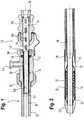
- Fig. 1shows a hand unit 10, coupled to the shaft 12 of a catheter delivery system for the stent 14 shown in Fig. 2 .
- the catheter shaft 12has an inner shaft 16 which is the push element of the catheter shaft.
- the stent 14is carried on the distal end of the inner shaft 16 and is radially confined by a roll back membrane 18 with a distal end 20 secured to the inner shaft 16 at a location just proximal of the proximal end of the stent 14.
- the membraneextends distally to the tip 22 of the catheter, at which point it reverses direction at a roll back annulus 24 and then advances proximally in a proximal overlapping run 25 down the length of the stent.
- the membrane 18is bonded to a catheter outer shaft component 26, in an overlap zone 28 at the distal end of the outer shaft 26.
- the pull hub 30has a bore 34 and a proximal end 36 which accommodates an O-ring 38 and retainer annulus 40.
- a female Luer lock connection 44to receive flushing liquid to flush the bore 34 defined by the pull hub 30.
- the inner shaft 16 of the catheterterminates at its proximal end in a telescopic tube arrangement of the push component of the hand unit 10.
- the telescopic arrangementfeatures an inner tube 50 with a distal end 52 that is received within the proximal end of the catheter inner shaft tube 16.
- Sleeving the inner tube 50 within its boreis the radially outer tube 54 of the telescopic arrangement.
- the outer telescope tube 54runs back proximally as far as a female Luer connector 56 to receive flushing liquid to flush the bore of the catheter inner shaft tube 16.
- Around the Luer 56is a push hub 58 so that one can push on the push hub 58 to push on the catheter shaft inner tube 16 and thereby hold the stent in position during its deployment.
- Collapsing of the telescopic arrangementis prevented by a series of tangs 60 that are each formed with a simple U-shaped cut through the wall thickness of the outer tube 54, each tang being predisposed to be inclined very slightly radially inwardly, thereby to bear on the proximal end of the inner tube 50 should any attempt be made to collapse the telescopic arrangement longitudinally. Pulling each tang 60 proximally past the proximal end of the inner tube 50 results in the issuance of an audible "click".
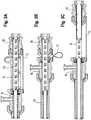
- FIG. 1To illustrate how the hand unit of Fig. 1 is capable of deploying the stent 14, attention is now invited to Figs. 3A, 3B and 3C of the drawings.
- a spacer 70 and a tether 72can be removed when the time comes to deploy the stent. It simply clips around the outer telescopic tube 54 and physically prevents the two hubs 30 and 58 from moving any closer together.
- the two hubscannot move further apart because the tether 72 that connects the two of them is taut. Unlike the spacer 70, the tether remains, connecting the two hubs, throughout the deployment process.
- the cylindrical radially outer surface of the outer telescopic tube 54is smooth and provides a smooth, circular cross section guide rail along which the pull hub 30 can slide proximally, without impediment once the spacer 70 has been taken away.
- FIG. 3Bshows that first step of the deployment process.
- the push hub 58has not moved but that the spacer 70 has been taken away and the pull hub 30 has been pulled back, by the distance of the spacer 70, until it lightly abuts the distal end of the push hub 58.
- This movementcollapses the tether 72 and also pulls back proximally the outer catheter shaft 26 sufficient to pull back proximally the roll back annulus 24 to a point some distance proximal of the distal end of the stent 14, in the illustrated case about half way along the length of the stent 14.
- the position shown in Fig. 3Bis only transient.
- the next stepis to pull proximally (rather than push distally) the push hub 58, thereby to extend telescopically the telescopic arrangement of the push component 50/54.
- the pull hub 30does not move axially relative to the push element, the inner shaft 16 of the catheter, so there is no further deployment of the implant during the proximal withdrawal of guide rail 54.
- the pull hub 30is once again free to embark on a run along the length of the guide rail surface of the outer telescope tube 54, in the proximal direction, thereby to carry the rolling annulus 24 along the length of the proximal half of the length of the stent 14, thereby to complete its release and deployment into the bodily lumen that has received the catheter delivery system.
- the inventionis not limited to the embodiments described above. Many modifications are possible.
- the elongate hand unitmay be provided without the catheter but may alternatively also comprise the catheter.
- the present inventionlends itself to modular construction of delivery systems for implants, tailored to the particular length of the specific implant to be delivered.
- delivery systemsfor implants, tailored to the particular length of the specific implant to be delivered.
- sterility issuescan be well managed.
- system design simpleis not only a way to keep manufacturing simple, but is also a way to minimise variability and uncertainty in the operating theatre.
Landscapes
- Health & Medical Sciences (AREA)
- Engineering & Computer Science (AREA)
- Biomedical Technology (AREA)
- Cardiology (AREA)
- Oral & Maxillofacial Surgery (AREA)
- Transplantation (AREA)
- Heart & Thoracic Surgery (AREA)
- Vascular Medicine (AREA)
- Life Sciences & Earth Sciences (AREA)
- Animal Behavior & Ethology (AREA)
- General Health & Medical Sciences (AREA)
- Public Health (AREA)
- Veterinary Medicine (AREA)
- Media Introduction/Drainage Providing Device (AREA)
Description
- This invention relates to a hand unit for a catheter device for the delivery of an elongate implant mounted on the distal end of the device.
- More particularly, this invention relates to an elongate hand unit for deploying an elongate implant from the distal end of a delivery catheter, which catheter has a shaft between the distal end carrying the implant and a proximal end to which the hand unit may be coupled, the shaft comprising a push element to maintain the position of the implant during deployment and a pull element to be pulled proximally relative to the push element, by a release distance sufficient to deploy the implant, the hand unit having a distal end and a proximal end separated by a hand unit length, and comprising a pull component and a push component, the pull component having a pull grip, to be gripped and pulled proximally by the release distance, sliding on the push component, thereby to pull the pull element proximally, thereby to deploy the implant, the push component to be operatively connected to the push element of the catheter shaft and having at its proximal end a push surface to receive during deployment of the implant a force that pushes on the push element shaft to resist proximal movement of the implant during deployment, the push component providing a guide rail that defines a guide path for the pull grip, with a guide path length along which the pull grip can slide proximally, from a distal to a proximal end of the guide rail whereby the proximal movement of the pull grip along the guide path deploys the implant.
- Catheter delivery systems for trans-luminal delivery of implants, particularly self-expanding stents, have a rich history in the patent literature. Early proposals were for a simple sheath radially surrounding the radially-compressed stent at the distal end of the catheter system, the sheath being pulled back proximally, to release the stent from its bed, progressively, starting at its distal end of the bed, within the stenting site or stenosis of the bodily lumen in which the catheter delivery system had been advanced. Readers will appreciate that, because the stent is self-expanding, it is pressing on the luminal surface of the surrounding sheath, up to the moment of its release from the sheath. Thus, friction forces between the stent and the surrounding sheath must be taken into account when devising a delivery system that will allow the sheath to slide proximally over the full length of the outwardly-pushing, self-expanding stent.
- The problems of friction will increase with the length of the stent, and the pressure on delivery system designers is to deliver ever-longer stents. Furthermore, there is steady pressure on stent delivery system designers to come up with systems that have ever-smaller passing diameters at the distal end of the catheter. The conventional unit of dimensions for diameters of systems to advance along a bodily lumen is the "French" which is one third of a millimeter. Thus, one millimeter is "3 French". To be able to reduce the passing diameter of a delivery system, for example from 7 French to 6 French, is a notable achievement.
- One way to respond to the challenge of friction forces between a proximally withdrawing sheath and a self-expanding stent confined within it is to adopt a "rolling membrane" sheath system, in which the sheath is at least double the length of the stent that it surrounds, being doubled back on itself at a point distally beyond the distal end of the stent. Then, proximal withdrawal of the radially outer doubled back portion of the sheath length will cause the "rolling edge" between the outer and inner sheath portions to retreat proximally, rolling proximally down the length of the stent, to release the stent progressively, as with a single layer surrounding sheath.
- Regardless of whether a conventional or rolling membrane sheath system is employed at the distal end of a stent delivery system, the delivery system requires some form of deployment mechanism provided at the proximal end of the stent delivery system to enable an operator to control at the proximal end the deployment of the distally located stent inside a patient. Typically, the stent is provided on the distal end of a push rod that extends from the proximal end to the distal end of the system. With this push rod held stationary, the user operates such a mechanism at the proximal end, resulting in the sheath system being pulled back, thereby deploying the stent, as described above.
- One stent deployment mechanism is disclosed in
US 2007/0244540 A1 (here "D1"). This mechanism involves the use of a thumb slider that is repeatedly translated distally and proximally, with each progressive proximal movement effecting progressive retraction of the sheath. A disadvantage of this deployment mechanism is the inability to deploy the stent in only one, or at least only a few, translations of the deployment mechanism. For lengthy stents, deploying the stent using this mechanism would prove a laborious task, requiring many translations. - However, once the distal end of the implant is in place on the wall of the lumen in the body that is receiving the implant, a swift retraction of the sheath, to deploy the remaining length of the implant in one smooth stroke, is not available from this device.
- D1 teaches the attractiveness of a hand unit that is physically small. The sheath of D1 is not a roll back membrane. Were it to be a roll back membrane, the distance it would have to be pulled back proximally would be doubled. The present invention aims to provide a simple and easy to manufacture hand unit that is small in size but yet is capable of deploying a lengthy implant covered by a roll back membrane.
- The documents laid open for Irish patent application
IE 20 040 094 - According to the present invention, a hand unit of the general form identified above is characterized by a guide path extender that is movable from a compact disposition in which the push surface is a first distance from the distal end of the hand unit to an extended disposition in which the push surface is a second distance, greater than the first distance, from the distal end of the hand unit, the guide path extender making available to the pull grip an increased guide path length.
- With the invention, the guide path extender provides a guide path length that is long enough to pull back proximally the pull element of the catheter shaft, far enough to deploy a lengthy implant at the distal end of the catheter, even if the implant is constrained by a roll back membrane that needs to be pulled back proximally by a distance double the length of the implant itself.
- Furthermore, the invention makes available a system to deploy an implant in which the pull grip travels over a linear path that is co-linear with the longitudinal axis of the implant. Providing such a path can maximise the tactile feedback that the operator obtains from the distal end of the implant delivery stem via the pull grip. Not only that; the transmission of deployment force from the pull grip to the membrane that radially restrains the implant till it is deployed is achieved most efficiently through a line of action that is as straight as possible and a minimum of end-to-end joints in the line of force transmission.
- The state of the art includes proposals to release a self-expanding stent from a delivery catheter with a hand unit that includes a reel on which a pull wire can be wound, the winding of the pull wire on the reel serving to pull back proximally a sheath surrounding the implant at the distal end of the catheter. Conveniently, successive squeezes of a trigger can be used to achieve successive stepwise rotatory movement of the reel, each squeeze of the trigger pulling back proximally the sheet surrounding the implant, by a step along the length of the implant. However, complexity is added by the need to convert the sheath surrounding the implant into a pull wire for winding up on the reel. Furthermore, some doctors prefer to deploy an implant in one smooth single proximal movement of a pull grip, and so are less comfortable with deployment using a large number of successive squeezes of a trigger. In principle, a single long stroke of the pull grip, to deploy the implant, is preferable whenever a more rigorously stepwise deployment procedure runs a risk of imposing on the bodily tissue of the lumen while receiving the implant any sort of axial stress along the length of the bodily lumen. The chances of such stresses being imposed on the tissue during a single full stroke release of the implant are likely to be significantly less. Minimising tissue trauma during implant deployment is of course a general aim in all implant deployment procedures and the present invention can help to minimise such trauma.
- Thus, a technical effect of the present invention is to minimise tissue trauma when deploying self-expanding implants of more than average length.
- One way to provide the extra guide rail length is to resort to a push component in the hand unit that is of the form of a telescopic tube arrangement. Effectively, the guide path extender extends distally of the guide path. Such an arrangement is likely to exhibit first and second telescopically arranged tubes, one radially inside the other and with a latch between them that permits the tubes to extend their length telescopically but which resists the reverse movement, to a smaller length. This is because the push surface is on the proximal end of the push element, and any tendency for the length of the telescopic tube arrangement to collapse could frustrate delivery of a pushing force to the distal end of the catheter where it is required to keep the implant in position during deployment. Such a latch can be very simply and economically provided by a series of detents, tangs or tabs on one of the tubes, that will abut an end surface on the other of the tubes to resist any telescopic collapsing relative movement between the two tubes. With a telescopic arrangement, the guide rail can be provided exclusively on the radially outer of the telescoping tubes, with no requirement for any guide rail surface on the radially inner of the two tubes. One example of such an arrangement can be seen in the accompanying drawings, described below. It may be convenient to arrange that the passage of each detent past the end of the other of the telescopic tubes results in an audible clicking sound, to inform the operator that the latch has engaged.
- Other than a telescopic arrangement, the push component can be provided as first and second guide rail portions (and optionally more guide rail portions), e.g. in the form of rods or tubes, that can couple together, co-linearly and, in the case of tubes, co-axially, to deliver together a guide rail and aggregate guide path length that is greater than that present on any of the guide rail portions individually. One can regard this as providing the guide path extender proximal of the guide path as such. Just as a chimney sweep can screw together endwise tube sections to advance a sweeping brush up a chimney, or a person unblocking drains can screw together endwise a series of rods that will be advanced along the length of a drain, so the implant deployer can take at least first and second push component rods or tubes and join them together endwise to provide a run of guide rail that is long enough to accommodate the full length of pull element of the implant delivery catheter that needs to be accommodated within the hand unit to release the implant from the distal end of the catheter. Of course, endwise assembly of second and further push component rods or tubes increases the length of the hand unit. However, the need for a short and compact hand unit is felt during assembly, packaging and transport of the delivery system. During deployment of the implant, a much greater length of the hand unit can be tolerated, temporarily.
- In another variant, reminiscent of a collapsible walking stick, the guide rail can be provided in portions linked end-to-end by elastic bands that allow the portions to be stowed side by side but which, on release, bring the portions into an end-to-end connected relationship to provide one long guide rail that is cylindrical with no irregularities on the continuous guide path surface.
- As to the push component of the hand unit, it will generally be convenient to provide the push surface on a push hub at the proximal end of the hand unit. That hub would conveniently receive a guidewire, in the case that the delivery catheter is an "over the wire" device. Otherwise, the push hub will conveniently include a coupling for a flushing line to deliver flushing liquid to flush the interior of the delivery catheter of gas prior to advancing the catheter into the bodily lumen that is to receive the catheter.
- Likewise, the pull grip can be provided in the form of a pull hub that slides on the guide rail and that pull hub can conveniently include a coupling for flushing liquid.
- In general, devices that are to be actuated often include one or other safety device that prevents premature actuation, and might require a "cocking" or "priming" action as a first step in the actuation process. So it can be with the hand units of the present invention. In particular, it can be useful to include a spacer that sets a minimum distance between the push surface and the pull grip, which spacer is removed prior to actuating the device. In particular embodiments, there may be advantage in having a device such as a tether that will set a maximum distance that separates the push surface and the pull grip. Such a device is illustrated in the accompanying drawings.
- The hand unit of the present invention will serve as part of an implant delivery catheter system. In one simple arrangement, the push element of the catheter has a proximal end portion that extends proximally into the hand unit and provides the said push component. In a delivery system that utilises a rolling membrane to deploy a self-expanding implant at the distal end of the system, the membrane can be extended back proximally, all the way to the pull component of the hand unit.
- For a better understanding of the present invention, and to show more clearly how the same may be carried into effect, reference will now be made, by way of example, to the accompanying drawings, in which
- Fig. 1
- is a section through the long axis of a hand unit in accordance with the present invention;
- Fig. 2
- is a section through the long axis of the distal end of a stent delivery catheter that has at its proximal end the hand unit of
Fig. 1 ; - Fig. 3A
- shows the hand unit of
Fig. 1 , in the same axial section, in a transport disposition, prior to actuation; - Fig. 3B
- is the same section as
Fig. 3A , but after a first step in the stent deployment process; and - Fig. 3C
- is the same section as
Figs. 3A and 3B , but showing the hand unit after a further step in the deployment process. Fig. 1 shows ahand unit 10, coupled to theshaft 12 of a catheter delivery system for thestent 14 shown inFig. 2 . Thecatheter shaft 12 has aninner shaft 16 which is the push element of the catheter shaft. As can be seen fromFig. 2 , thestent 14 is carried on the distal end of theinner shaft 16 and is radially confined by a roll backmembrane 18 with adistal end 20 secured to theinner shaft 16 at a location just proximal of the proximal end of thestent 14. The membrane extends distally to thetip 22 of the catheter, at which point it reverses direction at a roll backannulus 24 and then advances proximally in a proximal overlappingrun 25 down the length of the stent. A little way proximal of the stent, themembrane 18 is bonded to a catheterouter shaft component 26, in anoverlap zone 28 at the distal end of theouter shaft 26.- Following the
outer shaft 26 back to its proximal end, we find it gripped between apull hub 30 and acollar 32 threadably engaged with the pull hub. The pull hub has abore 34 and aproximal end 36 which accommodates an O-ring 38 andretainer annulus 40. In the cylindricalouter surface 42 of thepull hub 30 there is provided a femaleLuer lock connection 44 to receive flushing liquid to flush thebore 34 defined by thepull hub 30. - Turning to the
inner shaft 16 of the catheter, it terminates at its proximal end in a telescopic tube arrangement of the push component of thehand unit 10. The telescopic arrangement features aninner tube 50 with adistal end 52 that is received within the proximal end of the catheterinner shaft tube 16. Sleeving theinner tube 50 within its bore is the radiallyouter tube 54 of the telescopic arrangement. Theouter telescope tube 54 runs back proximally as far as afemale Luer connector 56 to receive flushing liquid to flush the bore of the catheterinner shaft tube 16. Around theLuer 56 is apush hub 58 so that one can push on thepush hub 58 to push on the catheter shaftinner tube 16 and thereby hold the stent in position during its deployment. Collapsing of the telescopic arrangement is prevented by a series oftangs 60 that are each formed with a simple U-shaped cut through the wall thickness of theouter tube 54, each tang being predisposed to be inclined very slightly radially inwardly, thereby to bear on the proximal end of theinner tube 50 should any attempt be made to collapse the telescopic arrangement longitudinally. Pulling eachtang 60 proximally past the proximal end of theinner tube 50 results in the issuance of an audible "click". - To illustrate how the hand unit of
Fig. 1 is capable of deploying thestent 14, attention is now invited toFigs. 3A, 3B and 3C of the drawings. - First, looking at
Fig. 3A , we see an axial gap between thepull hub 30 and thepush hub 58. The gap is preserved by aspacer 70 and atether 72. Thespacer 70 can be removed when the time comes to deploy the stent. It simply clips around the outertelescopic tube 54 and physically prevents the twohubs - The two hubs cannot move further apart because the
tether 72 that connects the two of them is taut. Unlike thespacer 70, the tether remains, connecting the two hubs, throughout the deployment process. The cylindrical radially outer surface of the outertelescopic tube 54 is smooth and provides a smooth, circular cross section guide rail along which thepull hub 30 can slide proximally, without impediment once thespacer 70 has been taken away. - Indeed,
Fig. 3B shows that first step of the deployment process. Note that thepush hub 58 has not moved but that thespacer 70 has been taken away and thepull hub 30 has been pulled back, by the distance of thespacer 70, until it lightly abuts the distal end of thepush hub 58. This movement collapses thetether 72 and also pulls back proximally theouter catheter shaft 26 sufficient to pull back proximally the roll backannulus 24 to a point some distance proximal of the distal end of thestent 14, in the illustrated case about half way along the length of thestent 14. - The position shown in
Fig. 3B is only transient. The next step is to pull proximally (rather than push distally) thepush hub 58, thereby to extend telescopically the telescopic arrangement of thepush component 50/54. During this movement, thepull hub 30 does not move axially relative to the push element, theinner shaft 16 of the catheter, so there is no further deployment of the implant during the proximal withdrawal ofguide rail 54. - With the movement of the push hub completed, proximal movement of the pull hub is once again possible until the
tether 72 once again goes taut. Reverse movement of the guide rail is prevented by that one of the series oftangs 60 which is immediately proximal of the proximal end of theinner tube 50 but which is first to engage with the proximal end as soon as any push force is imposed on thepush hub 58. After this proximal extension of the telescope guide rail arrangement, thepull hub 30 is once again free to embark on a run along the length of the guide rail surface of theouter telescope tube 54, in the proximal direction, thereby to carry the rollingannulus 24 along the length of the proximal half of the length of thestent 14, thereby to complete its release and deployment into the bodily lumen that has received the catheter delivery system. - It will apparent that there are many other ways in which to realise the present invention than the one shown in the drawings. One could, for example, provide a hand unit with the push hub on a separate tube component that is, prior to deployment, simply offered up to the proximal end of the push component of the hand unit, thereby to provide an increased length of the guide rail, considerably longer than the length of the hand unit without the extension tube.
- In another embodiment, there could be more than one such extension tube (in the manner of walking sticks, chimney rods or drain rods). While the illustrated telescope arrangement has only two tubes, it is envisaged that longer telescopes, of three or more tubes, would also be feasible. While the tangs shown in the drawings are a reliable and economical latch, skilled readers will be readily able to envisage other sorts of latch to endow a telescopic arrangement with the capability to resist telescopic collapse in length.
- The invention is not limited to the embodiments described above. Many modifications are possible. The elongate hand unit may be provided without the catheter but may alternatively also comprise the catheter.
- Notably, the present invention lends itself to modular construction of delivery systems for implants, tailored to the particular length of the specific implant to be delivered. With increasing maturity of technology in the world of stenting, it becomes ever more important to provide systems that lend themselves to straightforward manufacturing, in which sterility issues can be well managed. Keeping system design simple is not only a way to keep manufacturing simple, but is also a way to minimise variability and uncertainty in the operating theatre. Generally, the simpler a delivery system is, mechanically, the more reliable it will be in performance and therefore the safer for patients and the more favoured by their medical practitioners.
Claims (15)
- An elongate hand unit (10) for deploying an elongate implant (14) from the distal end of a delivery catheter (12), which catheter has a shaft between the distal end carrying the implant and a proximal end to which the hand unit may be coupled, the shaft comprising a push element (16) to maintain the position of the implant during deployment and a pull element (26) to be pulled proximally relative to the push element, by a release distance sufficient to deploy the implant,
the hand unit having a distal end and a proximal end separated by a hand unit length, and comprising a pull component (30) and a push component (58),
the pull component having a pull grip, to be gripped and pulled proximally by the release distance, sliding on the push component, thereby to pull the pull element proximally, thereby to deploy the implant
the push component to be operatively connected to the push element of the catheter shaft and having at its proximal end a push surface to receive during deployment of the implant a force that pushes on the push element shaft to resist proximal movement of the implant during deployment, the push component providing a guide rail (54) that defines a guide path for the pull grip, with a guide path length along which the pull grip can slide proximally, from a distal to a proximal end of the guide rail whereby the proximal movement of the pull grip along the guide path deploys the implant,
the hand unit beingcharacterised by
a guide path extender that is movable from a compact disposition in which the push surface is a first distance from the distal end of the hand unit to an extended disposition in which the push surface is a second distance, greater than the first distance, from the distal end of the hand unit, the guide path extender making available to the pull grip an increased guide path length. - Hand unit as claimed in claim 1, in which the push component comprises a telescopic tube arrangement that provides the guide path extender.
- Hand unit as claimed in claim 2, in which the telescopic tube arrangement includes first and second telescopically arranged tubes and a latch between them that permits the telescopic arrangement to increase in length but resists length reductions.
- Hand unit as claimed in claim 3, wherein the guide rail is on the radially outer of the first and second telescopically arranged tubes and not on the radially inner of the first and second tubes.
- Hand unit as claimed in claim 1, wherein the push component comprises a first and a second guide rail portion, which can couple together thereby to deliver an aggregate guide path length greater than that provided by each of the first and second portions individually, the first and second portions thereby providing the guide path extender.
- Hand unit as claimed in any one of the preceding claims wherein the push surface is on a push hub.
- Hand unit as claimed in claim 6, in which the push hub can receive a guide wire.
- Hand unit as claimed in claim 6 or 7, wherein the push hub includes a coupling (56) for a flushing liquid.
- Hand unit as claimed in any one of the preceding claims, wherein the pull grip is a pull hub and the guide rail is tubular.
- Hand unit as claimed in claim 9, wherein the pull hub includes a coupling (44) for a flushing liquid.
- Hand unit as claimed in any one of the preceding claims and including a tether (72) that sets a maximum distance separating the push surface and the pull grip.
- Hand unit as claimed in any one of the preceding claims and including a removable spacer (70) that sets a minimum distance separating the push surface and the pull grip.
- Implant delivery catheter (12) including a hand unit as claimed in any one of the preceding claims.
- Catheter as claimed in claim 13, with a push element with a proximal end portion that extends proximally into the hand unit to provide the said push component.
- Catheter as claimed in claim 13 or 14 with a rolling membrane (18) at the distal end that extends proximally as far as the pull component.
Applications Claiming Priority (2)
| Application Number | Priority Date | Filing Date | Title |
|---|---|---|---|
| NL2009648 | 2012-10-17 | ||
| PCT/EP2013/071712WO2014060511A1 (en) | 2012-10-17 | 2013-10-17 | Hand unit to release a self-expanding implant |
Publications (2)
| Publication Number | Publication Date |
|---|---|
| EP2908784A1 EP2908784A1 (en) | 2015-08-26 |
| EP2908784B1true EP2908784B1 (en) | 2017-07-12 |
Family
ID=47603974
Family Applications (1)
| Application Number | Title | Priority Date | Filing Date |
|---|---|---|---|
| EP13777290.1AActiveEP2908784B1 (en) | 2012-10-17 | 2013-10-17 | Hand unit to release a self-expanding implant |
Country Status (5)
| Country | Link |
|---|---|
| US (2) | US9687372B2 (en) |
| EP (1) | EP2908784B1 (en) |
| CA (1) | CA2874563C (en) |
| ES (1) | ES2638969T3 (en) |
| WO (1) | WO2014060511A1 (en) |
Families Citing this family (3)
| Publication number | Priority date | Publication date | Assignee | Title |
|---|---|---|---|---|
| CN110870811B (en) | 2018-08-31 | 2025-06-17 | 上海微创心通医疗科技有限公司 | Conveying device |
| JP7015495B2 (en)* | 2018-09-09 | 2022-02-03 | 上海医立泰生物科技有限公司 | Stent transport system |
| KR20220113934A (en)* | 2019-11-12 | 2022-08-17 | 마이크로벤션, 인코포레이티드 | Stent delivery systems and methods |
Citations (1)
| Publication number | Priority date | Publication date | Assignee | Title |
|---|---|---|---|---|
| IE20040094A1 (en)* | 2003-02-14 | 2004-09-22 | Salviac Ltd | Stent delivery and deployment system |
Family Cites Families (15)
| Publication number | Priority date | Publication date | Assignee | Title |
|---|---|---|---|---|
| US4846793A (en) | 1987-03-18 | 1989-07-11 | Endocon, Inc. | Injector for implanting multiple pellet medicaments |
| DE59208848D1 (en)* | 1991-10-11 | 1997-10-09 | Angiomed Ag | Device for expanding a stenosis |
| US5571168A (en)* | 1995-04-05 | 1996-11-05 | Scimed Lifesystems Inc | Pull back stent delivery system |
| US6551333B2 (en) | 2000-10-19 | 2003-04-22 | Ethicon Endo-Surgery, Inc. | Method for attaching hernia mesh |
| EP1465546B1 (en)* | 2001-11-29 | 2007-07-18 | Cook Incorporated | Medical device delivery system |
| US7326236B2 (en) | 2003-12-23 | 2008-02-05 | Xtent, Inc. | Devices and methods for controlling and indicating the length of an interventional element |
| US9211206B2 (en) | 2006-04-13 | 2015-12-15 | Medtronic Vascular, Inc. | Short handle for a long stent |
| US8535368B2 (en)* | 2006-05-19 | 2013-09-17 | Boston Scientific Scimed, Inc. | Apparatus for loading and delivering a stent |
| WO2009023221A1 (en) | 2007-08-13 | 2009-02-19 | William A. Cook Australia Pty. Ltd. | Deployment device |
| US8075607B2 (en) | 2007-12-27 | 2011-12-13 | Cook Medical Technologies Llc | Control handle |
| CA2711755A1 (en)* | 2008-01-24 | 2009-07-30 | Boston Scientific Scimed, Inc. | Apparatus and method for loading and delivering a stent having improved handles to control relative catheter component movement |
| US8475461B2 (en) | 2009-06-10 | 2013-07-02 | Life Spine, Inc. | Instruments for installing multi-section intervertebral spinal implants |
| US20120238806A1 (en)* | 2009-08-24 | 2012-09-20 | Quali-Med Gmbh | Implantation system with handle and catheter and method of use thereof |
| US9439652B2 (en)* | 2009-08-24 | 2016-09-13 | Qualimed Innovative Medizinprodukte Gmbh | Implantation device with handle and method of use thereof |
| US9023095B2 (en) | 2010-05-27 | 2015-05-05 | Idev Technologies, Inc. | Stent delivery system with pusher assembly |
- 2013
- 2013-10-17CACA2874563Apatent/CA2874563C/enactiveActive
- 2013-10-17WOPCT/EP2013/071712patent/WO2014060511A1/enactiveApplication Filing
- 2013-10-17ESES13777290.1Tpatent/ES2638969T3/enactiveActive
- 2013-10-17EPEP13777290.1Apatent/EP2908784B1/enactiveActive
- 2013-10-17USUS14/056,843patent/US9687372B2/enactiveActive
- 2017
- 2017-05-30USUS15/608,967patent/US20170258616A1/ennot_activeAbandoned
Patent Citations (1)
| Publication number | Priority date | Publication date | Assignee | Title |
|---|---|---|---|---|
| IE20040094A1 (en)* | 2003-02-14 | 2004-09-22 | Salviac Ltd | Stent delivery and deployment system |
Also Published As
| Publication number | Publication date |
|---|---|
| CA2874563A1 (en) | 2014-04-24 |
| US9687372B2 (en) | 2017-06-27 |
| CA2874563C (en) | 2021-01-12 |
| ES2638969T3 (en) | 2017-10-24 |
| WO2014060511A1 (en) | 2014-04-24 |
| US20140107757A1 (en) | 2014-04-17 |
| EP2908784A1 (en) | 2015-08-26 |
| US20170258616A1 (en) | 2017-09-14 |
Similar Documents
| Publication | Publication Date | Title |
|---|---|---|
| US9827122B2 (en) | System for a catheter | |
| JP6900440B2 (en) | A device for removing acute obstructions from blood vessels | |
| JP4903049B2 (en) | Catheter device | |
| JP5087300B2 (en) | Stent delivery system and method | |
| US7780693B2 (en) | Catheter | |
| EP1861156B1 (en) | Access catheter having dilation capability | |
| EP1408873B1 (en) | A catheter | |
| US20170105743A1 (en) | Devices and methods for removal of acute blockages from blood vessels | |
| EP1673036B1 (en) | Retrieval catheter | |
| MX2007016231A (en) | Catheter device. | |
| US11766272B2 (en) | Apparatus and methods for neurovascular endoluminal intervention | |
| US20170258616A1 (en) | Hand Unit to Release a Self-Expanding Implant | |
| CN106659575B (en) | The handle of deployment for medical device | |
| US20080195141A1 (en) | Backstop protection device and method of using the same | |
| IE20060620A1 (en) | A delivery catheter | |
| AU2002345311A1 (en) | A catheter | |
| IE20020531A1 (en) | A Catheter |
Legal Events
| Date | Code | Title | Description |
|---|---|---|---|
| PUAI | Public reference made under article 153(3) epc to a published international application that has entered the european phase | Free format text:ORIGINAL CODE: 0009012 | |
| 17P | Request for examination filed | Effective date:20141127 | |
| AK | Designated contracting states | Kind code of ref document:A1 Designated state(s):AL AT BE BG CH CY CZ DE DK EE ES FI FR GB GR HR HU IE IS IT LI LT LU LV MC MK MT NL NO PL PT RO RS SE SI SK SM TR | |
| AX | Request for extension of the european patent | Extension state:BA ME | |
| DAX | Request for extension of the european patent (deleted) | ||
| 17Q | First examination report despatched | Effective date:20160714 | |
| GRAP | Despatch of communication of intention to grant a patent | Free format text:ORIGINAL CODE: EPIDOSNIGR1 | |
| INTG | Intention to grant announced | Effective date:20170309 | |
| GRAS | Grant fee paid | Free format text:ORIGINAL CODE: EPIDOSNIGR3 | |
| GRAA | (expected) grant | Free format text:ORIGINAL CODE: 0009210 | |
| AK | Designated contracting states | Kind code of ref document:B1 Designated state(s):AL AT BE BG CH CY CZ DE DK EE ES FI FR GB GR HR HU IE IS IT LI LT LU LV MC MK MT NL NO PL PT RO RS SE SI SK SM TR | |
| REG | Reference to a national code | Ref country code:GB Ref legal event code:FG4D | |
| REG | Reference to a national code | Ref country code:CH Ref legal event code:EP | |
| REG | Reference to a national code | Ref country code:AT Ref legal event code:REF Ref document number:907640 Country of ref document:AT Kind code of ref document:T Effective date:20170715 | |
| REG | Reference to a national code | Ref country code:IE Ref legal event code:FG4D | |
| REG | Reference to a national code | Ref country code:DE Ref legal event code:R096 Ref document number:602013023473 Country of ref document:DE | |
| REG | Reference to a national code | Ref country code:ES Ref legal event code:FG2A Ref document number:2638969 Country of ref document:ES Kind code of ref document:T3 Effective date:20171024 | |
| REG | Reference to a national code | Ref country code:FR Ref legal event code:PLFP Year of fee payment:5 | |
| REG | Reference to a national code | Ref country code:NL Ref legal event code:MP Effective date:20170712 | |
| REG | Reference to a national code | Ref country code:LT Ref legal event code:MG4D | |
| REG | Reference to a national code | Ref country code:AT Ref legal event code:MK05 Ref document number:907640 Country of ref document:AT Kind code of ref document:T Effective date:20170712 | |
| PG25 | Lapsed in a contracting state [announced via postgrant information from national office to epo] | Ref country code:AT Free format text:LAPSE BECAUSE OF FAILURE TO SUBMIT A TRANSLATION OF THE DESCRIPTION OR TO PAY THE FEE WITHIN THE PRESCRIBED TIME-LIMIT Effective date:20170712 Ref country code:SE Free format text:LAPSE BECAUSE OF FAILURE TO SUBMIT A TRANSLATION OF THE DESCRIPTION OR TO PAY THE FEE WITHIN THE PRESCRIBED TIME-LIMIT Effective date:20170712 Ref country code:FI Free format text:LAPSE BECAUSE OF FAILURE TO SUBMIT A TRANSLATION OF THE DESCRIPTION OR TO PAY THE FEE WITHIN THE PRESCRIBED TIME-LIMIT Effective date:20170712 Ref country code:HR Free format text:LAPSE BECAUSE OF FAILURE TO SUBMIT A TRANSLATION OF THE DESCRIPTION OR TO PAY THE FEE WITHIN THE PRESCRIBED TIME-LIMIT Effective date:20170712 Ref country code:NO Free format text:LAPSE BECAUSE OF FAILURE TO SUBMIT A TRANSLATION OF THE DESCRIPTION OR TO PAY THE FEE WITHIN THE PRESCRIBED TIME-LIMIT Effective date:20171012 Ref country code:LT Free format text:LAPSE BECAUSE OF FAILURE TO SUBMIT A TRANSLATION OF THE DESCRIPTION OR TO PAY THE FEE WITHIN THE PRESCRIBED TIME-LIMIT Effective date:20170712 Ref country code:NL Free format text:LAPSE BECAUSE OF FAILURE TO SUBMIT A TRANSLATION OF THE DESCRIPTION OR TO PAY THE FEE WITHIN THE PRESCRIBED TIME-LIMIT Effective date:20170712 | |
| PG25 | Lapsed in a contracting state [announced via postgrant information from national office to epo] | Ref country code:PL Free format text:LAPSE BECAUSE OF FAILURE TO SUBMIT A TRANSLATION OF THE DESCRIPTION OR TO PAY THE FEE WITHIN THE PRESCRIBED TIME-LIMIT Effective date:20170712 Ref country code:LV Free format text:LAPSE BECAUSE OF FAILURE TO SUBMIT A TRANSLATION OF THE DESCRIPTION OR TO PAY THE FEE WITHIN THE PRESCRIBED TIME-LIMIT Effective date:20170712 Ref country code:RS Free format text:LAPSE BECAUSE OF FAILURE TO SUBMIT A TRANSLATION OF THE DESCRIPTION OR TO PAY THE FEE WITHIN THE PRESCRIBED TIME-LIMIT Effective date:20170712 Ref country code:IS Free format text:LAPSE BECAUSE OF FAILURE TO SUBMIT A TRANSLATION OF THE DESCRIPTION OR TO PAY THE FEE WITHIN THE PRESCRIBED TIME-LIMIT Effective date:20171112 Ref country code:GR Free format text:LAPSE BECAUSE OF FAILURE TO SUBMIT A TRANSLATION OF THE DESCRIPTION OR TO PAY THE FEE WITHIN THE PRESCRIBED TIME-LIMIT Effective date:20171013 Ref country code:BG Free format text:LAPSE BECAUSE OF FAILURE TO SUBMIT A TRANSLATION OF THE DESCRIPTION OR TO PAY THE FEE WITHIN THE PRESCRIBED TIME-LIMIT Effective date:20171012 | |
| REG | Reference to a national code | Ref country code:DE Ref legal event code:R097 Ref document number:602013023473 Country of ref document:DE | |
| PG25 | Lapsed in a contracting state [announced via postgrant information from national office to epo] | Ref country code:RO Free format text:LAPSE BECAUSE OF FAILURE TO SUBMIT A TRANSLATION OF THE DESCRIPTION OR TO PAY THE FEE WITHIN THE PRESCRIBED TIME-LIMIT Effective date:20170712 Ref country code:CZ Free format text:LAPSE BECAUSE OF FAILURE TO SUBMIT A TRANSLATION OF THE DESCRIPTION OR TO PAY THE FEE WITHIN THE PRESCRIBED TIME-LIMIT Effective date:20170712 Ref country code:DK Free format text:LAPSE BECAUSE OF FAILURE TO SUBMIT A TRANSLATION OF THE DESCRIPTION OR TO PAY THE FEE WITHIN THE PRESCRIBED TIME-LIMIT Effective date:20170712 | |
| PLBE | No opposition filed within time limit | Free format text:ORIGINAL CODE: 0009261 | |
| STAA | Information on the status of an ep patent application or granted ep patent | Free format text:STATUS: NO OPPOSITION FILED WITHIN TIME LIMIT | |
| PG25 | Lapsed in a contracting state [announced via postgrant information from national office to epo] | Ref country code:SM Free format text:LAPSE BECAUSE OF FAILURE TO SUBMIT A TRANSLATION OF THE DESCRIPTION OR TO PAY THE FEE WITHIN THE PRESCRIBED TIME-LIMIT Effective date:20170712 Ref country code:MC Free format text:LAPSE BECAUSE OF FAILURE TO SUBMIT A TRANSLATION OF THE DESCRIPTION OR TO PAY THE FEE WITHIN THE PRESCRIBED TIME-LIMIT Effective date:20170712 Ref country code:SK Free format text:LAPSE BECAUSE OF FAILURE TO SUBMIT A TRANSLATION OF THE DESCRIPTION OR TO PAY THE FEE WITHIN THE PRESCRIBED TIME-LIMIT Effective date:20170712 Ref country code:EE Free format text:LAPSE BECAUSE OF FAILURE TO SUBMIT A TRANSLATION OF THE DESCRIPTION OR TO PAY THE FEE WITHIN THE PRESCRIBED TIME-LIMIT Effective date:20170712 | |
| REG | Reference to a national code | Ref country code:CH Ref legal event code:PL | |
| 26N | No opposition filed | Effective date:20180413 | |
| REG | Reference to a national code | Ref country code:IE Ref legal event code:MM4A | |
| PG25 | Lapsed in a contracting state [announced via postgrant information from national office to epo] | Ref country code:LI Free format text:LAPSE BECAUSE OF NON-PAYMENT OF DUE FEES Effective date:20171031 Ref country code:CH Free format text:LAPSE BECAUSE OF NON-PAYMENT OF DUE FEES Effective date:20171031 Ref country code:LU Free format text:LAPSE BECAUSE OF NON-PAYMENT OF DUE FEES Effective date:20171017 | |
| REG | Reference to a national code | Ref country code:BE Ref legal event code:MM Effective date:20171031 | |
| PG25 | Lapsed in a contracting state [announced via postgrant information from national office to epo] | Ref country code:BE Free format text:LAPSE BECAUSE OF NON-PAYMENT OF DUE FEES Effective date:20171031 Ref country code:SI Free format text:LAPSE BECAUSE OF FAILURE TO SUBMIT A TRANSLATION OF THE DESCRIPTION OR TO PAY THE FEE WITHIN THE PRESCRIBED TIME-LIMIT Effective date:20170712 | |
| REG | Reference to a national code | Ref country code:FR Ref legal event code:PLFP Year of fee payment:6 | |
| PG25 | Lapsed in a contracting state [announced via postgrant information from national office to epo] | Ref country code:MT Free format text:LAPSE BECAUSE OF NON-PAYMENT OF DUE FEES Effective date:20171017 | |
| PG25 | Lapsed in a contracting state [announced via postgrant information from national office to epo] | Ref country code:IE Free format text:LAPSE BECAUSE OF NON-PAYMENT OF DUE FEES Effective date:20171017 | |
| PG25 | Lapsed in a contracting state [announced via postgrant information from national office to epo] | Ref country code:HU Free format text:LAPSE BECAUSE OF FAILURE TO SUBMIT A TRANSLATION OF THE DESCRIPTION OR TO PAY THE FEE WITHIN THE PRESCRIBED TIME-LIMIT; INVALID AB INITIO Effective date:20131017 | |
| PG25 | Lapsed in a contracting state [announced via postgrant information from national office to epo] | Ref country code:CY Free format text:LAPSE BECAUSE OF FAILURE TO SUBMIT A TRANSLATION OF THE DESCRIPTION OR TO PAY THE FEE WITHIN THE PRESCRIBED TIME-LIMIT Effective date:20170712 | |
| PG25 | Lapsed in a contracting state [announced via postgrant information from national office to epo] | Ref country code:MK Free format text:LAPSE BECAUSE OF FAILURE TO SUBMIT A TRANSLATION OF THE DESCRIPTION OR TO PAY THE FEE WITHIN THE PRESCRIBED TIME-LIMIT Effective date:20170712 | |
| PG25 | Lapsed in a contracting state [announced via postgrant information from national office to epo] | Ref country code:TR Free format text:LAPSE BECAUSE OF FAILURE TO SUBMIT A TRANSLATION OF THE DESCRIPTION OR TO PAY THE FEE WITHIN THE PRESCRIBED TIME-LIMIT Effective date:20170712 | |
| PG25 | Lapsed in a contracting state [announced via postgrant information from national office to epo] | Ref country code:PT Free format text:LAPSE BECAUSE OF FAILURE TO SUBMIT A TRANSLATION OF THE DESCRIPTION OR TO PAY THE FEE WITHIN THE PRESCRIBED TIME-LIMIT Effective date:20170712 | |
| PG25 | Lapsed in a contracting state [announced via postgrant information from national office to epo] | Ref country code:AL Free format text:LAPSE BECAUSE OF FAILURE TO SUBMIT A TRANSLATION OF THE DESCRIPTION OR TO PAY THE FEE WITHIN THE PRESCRIBED TIME-LIMIT Effective date:20170712 | |
| PGFP | Annual fee paid to national office [announced via postgrant information from national office to epo] | Ref country code:GB Payment date:20240919 Year of fee payment:12 | |
| PGFP | Annual fee paid to national office [announced via postgrant information from national office to epo] | Ref country code:FR Payment date:20240919 Year of fee payment:12 | |
| PGFP | Annual fee paid to national office [announced via postgrant information from national office to epo] | Ref country code:IT Payment date:20240919 Year of fee payment:12 | |
| PGFP | Annual fee paid to national office [announced via postgrant information from national office to epo] | Ref country code:DE Payment date:20240919 Year of fee payment:12 | |
| PGFP | Annual fee paid to national office [announced via postgrant information from national office to epo] | Ref country code:ES Payment date:20241104 Year of fee payment:12 |