EP2906177B1 - Child feeding system - Google Patents
Child feeding systemDownload PDFInfo
- Publication number
- EP2906177B1 EP2906177B1EP13846217.1AEP13846217AEP2906177B1EP 2906177 B1EP2906177 B1EP 2906177B1EP 13846217 AEP13846217 AEP 13846217AEP 2906177 B1EP2906177 B1EP 2906177B1
- Authority
- EP
- European Patent Office
- Prior art keywords
- spout
- nipple
- pouch
- connector
- holder
- Prior art date
- Legal status (The legal status is an assumption and is not a legal conclusion. Google has not performed a legal analysis and makes no representation as to the accuracy of the status listed.)
- Active
Links
Images


Classifications
- A—HUMAN NECESSITIES
- A61—MEDICAL OR VETERINARY SCIENCE; HYGIENE
- A61J—CONTAINERS SPECIALLY ADAPTED FOR MEDICAL OR PHARMACEUTICAL PURPOSES; DEVICES OR METHODS SPECIALLY ADAPTED FOR BRINGING PHARMACEUTICAL PRODUCTS INTO PARTICULAR PHYSICAL OR ADMINISTERING FORMS; DEVICES FOR ADMINISTERING FOOD OR MEDICINES ORALLY; BABY COMFORTERS; DEVICES FOR RECEIVING SPITTLE
- A61J9/00—Feeding-bottles in general
- A61J9/005—Non-rigid or collapsible feeding-bottles
- A—HUMAN NECESSITIES
- A61—MEDICAL OR VETERINARY SCIENCE; HYGIENE
- A61J—CONTAINERS SPECIALLY ADAPTED FOR MEDICAL OR PHARMACEUTICAL PURPOSES; DEVICES OR METHODS SPECIALLY ADAPTED FOR BRINGING PHARMACEUTICAL PRODUCTS INTO PARTICULAR PHYSICAL OR ADMINISTERING FORMS; DEVICES FOR ADMINISTERING FOOD OR MEDICINES ORALLY; BABY COMFORTERS; DEVICES FOR RECEIVING SPITTLE
- A61J11/00—Teats
- A61J11/04—Teats with means for fastening to bottles
- A61J11/045—Teats with means for fastening to bottles with interlocking means, e.g. protrusions or indentations on the teat
- A—HUMAN NECESSITIES
- A61—MEDICAL OR VETERINARY SCIENCE; HYGIENE
- A61J—CONTAINERS SPECIALLY ADAPTED FOR MEDICAL OR PHARMACEUTICAL PURPOSES; DEVICES OR METHODS SPECIALLY ADAPTED FOR BRINGING PHARMACEUTICAL PRODUCTS INTO PARTICULAR PHYSICAL OR ADMINISTERING FORMS; DEVICES FOR ADMINISTERING FOOD OR MEDICINES ORALLY; BABY COMFORTERS; DEVICES FOR RECEIVING SPITTLE
- A61J9/00—Feeding-bottles in general
- A61J9/001—Feeding-bottles in general with inner liners
- A—HUMAN NECESSITIES
- A61—MEDICAL OR VETERINARY SCIENCE; HYGIENE
- A61J—CONTAINERS SPECIALLY ADAPTED FOR MEDICAL OR PHARMACEUTICAL PURPOSES; DEVICES OR METHODS SPECIALLY ADAPTED FOR BRINGING PHARMACEUTICAL PRODUCTS INTO PARTICULAR PHYSICAL OR ADMINISTERING FORMS; DEVICES FOR ADMINISTERING FOOD OR MEDICINES ORALLY; BABY COMFORTERS; DEVICES FOR RECEIVING SPITTLE
- A61J9/00—Feeding-bottles in general
- A61J9/06—Holders for bottles
- A—HUMAN NECESSITIES
- A61—MEDICAL OR VETERINARY SCIENCE; HYGIENE
- A61M—DEVICES FOR INTRODUCING MEDIA INTO, OR ONTO, THE BODY; DEVICES FOR TRANSDUCING BODY MEDIA OR FOR TAKING MEDIA FROM THE BODY; DEVICES FOR PRODUCING OR ENDING SLEEP OR STUPOR
- A61M1/00—Suction or pumping devices for medical purposes; Devices for carrying-off, for treatment of, or for carrying-over, body-liquids; Drainage systems
- A61M1/06—Milking pumps
- A61M1/062—Pump accessories
- B—PERFORMING OPERATIONS; TRANSPORTING
- B65—CONVEYING; PACKING; STORING; HANDLING THIN OR FILAMENTARY MATERIAL
- B65B—MACHINES, APPARATUS OR DEVICES FOR, OR METHODS OF, PACKAGING ARTICLES OR MATERIALS; UNPACKING
- B65B3/00—Packaging plastic material, semiliquids, liquids or mixed solids and liquids, in individual containers or receptacles, e.g. bags, sacks, boxes, cartons, cans, or jars
- B65B3/04—Methods of, or means for, filling the material into the containers or receptacles
- B65B3/17—Methods of, or means for, filling the material into the containers or receptacles for filling valve bags
- B—PERFORMING OPERATIONS; TRANSPORTING
- B65—CONVEYING; PACKING; STORING; HANDLING THIN OR FILAMENTARY MATERIAL
- B65B—MACHINES, APPARATUS OR DEVICES FOR, OR METHODS OF, PACKAGING ARTICLES OR MATERIALS; UNPACKING
- B65B37/00—Supplying or feeding fluent-solid, plastic, or liquid material, or loose masses of small articles, to be packaged
- B65B37/06—Supplying or feeding fluent-solid, plastic, or liquid material, or loose masses of small articles, to be packaged by pistons or pumps
- B—PERFORMING OPERATIONS; TRANSPORTING
- B65—CONVEYING; PACKING; STORING; HANDLING THIN OR FILAMENTARY MATERIAL
- B65B—MACHINES, APPARATUS OR DEVICES FOR, OR METHODS OF, PACKAGING ARTICLES OR MATERIALS; UNPACKING
- B65B7/00—Closing containers or receptacles after filling
- B65B7/16—Closing semi-rigid or rigid containers or receptacles not deformed by, or not taking-up shape of, contents, e.g. boxes or cartons
- B65B7/28—Closing semi-rigid or rigid containers or receptacles not deformed by, or not taking-up shape of, contents, e.g. boxes or cartons by applying separate preformed closures, e.g. lids, covers
- B65B7/2835—Closing semi-rigid or rigid containers or receptacles not deformed by, or not taking-up shape of, contents, e.g. boxes or cartons by applying separate preformed closures, e.g. lids, covers applying and rotating preformed threaded caps
- A—HUMAN NECESSITIES
- A61—MEDICAL OR VETERINARY SCIENCE; HYGIENE
- A61J—CONTAINERS SPECIALLY ADAPTED FOR MEDICAL OR PHARMACEUTICAL PURPOSES; DEVICES OR METHODS SPECIALLY ADAPTED FOR BRINGING PHARMACEUTICAL PRODUCTS INTO PARTICULAR PHYSICAL OR ADMINISTERING FORMS; DEVICES FOR ADMINISTERING FOOD OR MEDICINES ORALLY; BABY COMFORTERS; DEVICES FOR RECEIVING SPITTLE
- A61J9/00—Feeding-bottles in general
- A61J9/08—Protective covers for bottles
- A61J9/085—Lids for closing the bottle
Definitions
- the present inventionrelates to an infant feeding system.
- baby feedershave taken the form of a generally cylindrical bottle (typically, glass or plastic) and a removable nipple closing one end of the bottle.
- the nippleis commonly secured to the bottle by a threaded circular ring or collar having a central hole through which the nipple protrudes and which holds it securely to the bottle.
- An exampleis U.S. Patent No. 8,113,364, issued Feb. 14, 2012 to Ladan Asadi .
- Some baby feedersattach a removable nipple directly to a disposable feeder body.
- An exampleis U.S. Patent Application Pub. No. 2012/0234790 A1 .
- TM breastmilk bagsMany kinds of flexible, reclosable bags are known and used for food storage, including liquid foods, and some of these are used for receiving storing breast milk.
- One exampleis the Medela TM "pump and save" TM breastmilk bag.
- This bagis essentially a flat pouch closed on three sides but having a throat or opening extending the width of the bag on the top side through which the bag may be filled when opened. The bag is closed by forcing a rib along the top into a corresponding channel to form a friction seal. A separate feeder bottle is required for subsequent feeding of the contents.
- US 2002/0017528discloses a drink spout system including a valve assembly to regulate the flow of the drink fluid through the drink spout and to prevent drink fluid from being unintentionally dispensed from the drink container when the drink container is pierced by the drink spout system or when the drink container is tipped over or dropped.
- US2011/0151069discloses an infant feeding system comprising a sterile sealed laminated bag having a predetermined quantity of liquid infant food sealed therein, a compressed integral sterile teat sealed with the bag closure and/or spout and a protective cap for the teat, the system being arranged such that the cap can be removed to enable the infant to feed from the sterile teat and food.
- an infant feeding systemaccording to claim 1.
- Coupling the spout of the spout pouch to the breast pumpmay include coupling an adapter to the spout.
- the adaptermay have a threaded end configured to mate with threads on the breast pump.
- the spoutmay have a cross-sectional area greater than about three square centimeters.
- the nippleincludes a connector having an axial bore that is coupled to an orifice in the nipple, the connector forms a liquid tight seal with the spout of the spout pouch, and coupling the nipple to the spout includes inserting the connector into the spout.
- the connectormay have an inlet region and the inlet region further includes a circumferentially disposed flange, the spout may include a feature configured to receive the flange, and coupling the nipple to the spout may include inserting the connector into the spout until the flange has engaged with the feature.
- the featuremay be a recess or a ridge in the spout.
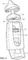
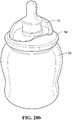
- Fig. 1is a perspective view of an assembled infant feeding system 10.
- the infant feeding system 10may include a holder 12, a spout pouch 14, a nipple 16 (shown in Fig. 2 ), and a cover 18.
- the spout pouch 14snaps into the holder 12.
- a rigid spout 20(described in more detail below) snaps into a feature on the holder 12, after being forced through a narrow gap in the holder 12.
- the spout pouch 14may be inserted into the holder 12 by passing through openings either in the bottom, sides, front, and/or back of the holder 12.
- the cover 18may be coupled to the nipple 16 or holder 12 by any of a friction fit, a snap fit, a magnetic coupling, a connection that requires a twisting action, or other type of connection.
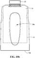
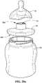
- Fig. 2is an exploded view of the infant feeding system 10 with the spout pouch 14 and cap 22 being assembled into the holder 12, and a nipple 16 and nipple cover 18.
- the spout pouch 14has a spout 20 that is configured to snap fit into the holder 12.
- the holder 12may be a thin-walled plastic shell, designed to hold the generally rigid spout 20 of the spout pouch 14.
- the connection between the spout 20 and holder 12may be any of a friction fit, a snap fit, a magnetic coupling, a connection that requires a twisting action, or other type of connection.
- the nipple 16is oblong in shape, for the purpose of a more ergonomic connection with an infant's mouth.
- the nipple 16connects to the spout 20 of the spout pouch 14 by a connector 24 (shown in more detail in Figs. 15a-15d ) on the bottom of the nipple 16.
- the connector 24has a hollow bore 26, through which liquids, foods, pastes, or gels pass from the pouch into the infant's mouth. In use, the connector 24 is pushed into the opening of the spout 20, creating a liquid-tight connection between the connector 24 and the spout 20.
- the connector 24may be slightly larger in size than the opening of the spout 20, but the connector 24 may be made of a compressible material, so it may be forced into the opening of the spout 20.
- the nipple 16is a single piece, made of a single material.
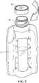
- Fig. 3is a perspective view of a cap 22 being assembled on to a spout pouch 14.
- the spout 20 of the spout pouch 14may be made of a generally rigid material, and is configured to receive a cap 22 capable of forming a water tight seal.
- the cap 22may be threaded, having helical features which interact with features on the spout 20, causing the cap 22 to form a liquid-tight seal with the spout when the cap 22 is twisted relative to the spout 20.
- the cap 22may be pressed, pulled, or twisted into place onto the spout 20.
- connection between the cap 22 and spout 20may be an interference fit (e.g., where two or more elements are forced together, causing the materials to deform at their interface), a friction fit (e.g., where the cap is held to the spout by friction), a snap fit, or a latch fit (e.g., where a pressing, pulling, twisting action is required to secure the cap to the spout).
- the pouch 14 materialis a thin, flexible plastic film
- the spout 20is a thicker, more rigid plastic material.
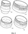
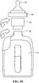
- Fig. 4is an exploded, perspective view of a spout pouch 14 being connected to one end of a breast pump 28, using a threaded adapter 30.
- the adapteris coupled to the spout 20 of the spout pouch 14, and the end of the breast pump 28 is coupled to the adapter 30.
- the breast pumpis then operated to express breast milk into the spout pouch 14 so that the spout pouch 14 collects the expressed breast milk.
- the spout pouch 14is configured to receive the breast milk that is pumped from a woman's breast by a breast pump.
- various types of adapterssuch as shown in Fig.
- connection between adapter 30 and spout pouch 14may be any of an interference fit, a friction fit, a snap fit, or a latch fit.
- connection between adapter and breast pumpmay be any of an interference fit, a friction fit, a snap fit, or a latch fit. Connecting the adapter 30 to the end of the breast pump 28, or connecting the adapter 30 to the spout 20 of the spout pouch 14 may require any of (or any combination of) twisting, pushing, pulling, or squeezing.
- the spout 20may couple directly to the outlet of a breast pump 28, by any of the means listed above, without the need for an adapter.
- the spout pouch 14may be held in a holder 12 while the spout pouch 14 is coupled to the adapter, or to a breast pump, or both.
- a holder 12may be used to provide a stable base for holding the spout pouch 14 during and after collecting milk using a breast pump.
- the holder 12, and its connection to the spout pouch 14,are described further below.
- Fig. 5shows multiple adapters which may be used to couple spout pouches 14 to breast pumps, for collecting breast milk. Additionally, in examples not belonging to the invention, these adapters 30 may be used to couple feeding nipples to spout pouches, for the purpose of feeding an infant. Since there are multiple different brands of breast pumps, there are many different types of connections required to couple the spout pouches 14 to the outlets 28 of a variety of breast pumps available on the market. Different adapters may be provided, with different types of connections, for coupling to a wide range of breast pumps for collection of pumped breast milk. These connections may include any of a threaded connection, an interference fit, a friction fit, a snap fit, or a latch fit.
- the other side of the adapteris coupled to the spout of the spout pouch, to allow liquid to flow into the pouch.
- the types of connections between the adapter and the nipplemay be any of the connection types listed above.
- the connection between the adapter and the nipplewill be a threaded connection.
- the adapter 30 used to couple a breast pump to the spout pouchmay be the same adapter that is used to couple a feeding nipple to the spout pouch.
- an infantcan be fed using only the spout pouch 14 and a nipple 16.
- a spout pouch, an adapter, and a nipplemay be used.
- a holder 12is used to hold the spout pouch during feeding, in conjunction with either an adapter and a nipple or a nipple alone.
- Fig. 6shows a spout pouch 14 with cap 22 assembled to form a liquid tight seal.
- the spoutis coupled to the pouch to form a liquid-tight vessel, designed for holding liquids or foods for infant or child feeding.
- An infant or childmay feed directly from the pouch, either by passing the liquid from the pouch, through the spout into the infant's mouth (directly or indirectly), or the pouch may be used for storage only, and the contents may be transferred to another container for feeding.
- different feeding devicesmay be used in conjunction with the spout pouch.
- nipples, valves, openings, spoons, feeding spouts, and other devices for interfacing with an infant's or child's mouthmay be connected to the spout of the spout pouch.
- Various types of connectionsmay be used for coupling these feeding devices to the spout.
- connectionsare: threaded connections, an interference fit (e.g., where two or more elements are forced together, causing the materials to deform at their interface), a friction fit (e.g., where the feeding device is held to the spout by friction), a snap fit (e.g., such as described below with the nipple and feeding utensil connectors), or a latch fit (e.g., where a pressing, pulling, twisting action is required to secure the feeding device to the spout).
- feeding devicesare: nipples, perforated containers, openings, spoons, feeding spouts, and valves.
- an infant or childcould feed directly from the pouch without a feeding device attached - the infant or child could simply pour or suck the contents of the pouch through the pouch and into his or her mouth.
- a spoon, a fork, a straw, or other utensilmay be passed through the spout in order to pick up and remove contents of the pouch for feeding.
- the connection between the cap and spoutmay be any of the types of connections listed previously.
- the spout 20has a cross-sectional area greater than about three square centimeters.
- Fig. 7is an exploded view showing a feeding nipple inside its case 32.
- the infant nipple case 32includes a nipple cover 18 and a base 34 that cover and protect a nipple 16.
- the case 32 componentsserve three purposes.
- the nipple cover 18 and base 34 of the case 32combine to form a protective case for the nipple 16; 2) the nipple cover 18 of the case can be used as a cover for the nipple 16 when the nipple 16 is assembled to the spout pouch 14, and the spout pouch 14 is assembled to the holder 12; and 3) the nipple cover 18 of the case can be used as a tool to push the nipple 16 into the spout 20 of the spout pouch 14, avoiding the necessity of the user touching the nipple 16 directly with his or her hands and potentially contaminating it.
- Fig. 8is a perspective view showing the nipple 16 assembled to the spout pouch 14, for the purpose of feeding an infant.
- This figureshows the nipple 16 pushed into the spout 20 of the spout pouch14.
- the nipple 16is pushed into the spout 20 of the spout pouch 14, and an infant could be fed directly from the spout pouch 14.
- Liquids contained within the spout pouch 14would flow through the spout 20 and nipple 16, through an orifice 36 in the nipple 16 (described in more detail below in Figs. 15a-15d ), into the infant's mouth.
- the spout pouch 14is held in a holder 12 (described in more detail in Figs. 10a-11b ).
- the spout pouch 14may be held in a holder 12, and a nipple cover 18 may be used to cover the nipple 16 to protect it from contamination (as described above in Fig. 7 ).
- the nipple(including a liquid-tight connector for connection to the spout 20) is made of a single piece of material.
- the nipple and its connectormay be made of multiple components (as described in more detail below in Figs. 19a-19b ).
- Fig. 9is a perspective view of a holder 12 for a spout pouch 14 according to embodiments of the present invention.
- the holder 12may be a thin-walled plastic shell, with openings on the top 12a, bottom 12b, front 12c, and/or back 12d of the holder.
- the opening 38a on the top 12a of the holdermay be a C-shaped opening that is configured to receive a portion of the spout 20 of the spout pouch 14, so as to couple the spout 20 to the holder 12 by way of a snap fit configuration, although other shaped top openings may also be used.
- the snap fit configurationwill be described in more detail below.
- the holder 12may have an opening 38b in the bottom 12b of the holder 12, an opening 38c in the front 12c of the holder 12, and/or an opening 38d in the back 12d of the holder 12.
- These openingscan be used for any of inserting the pouch 14 into the holder; squeezing the pouch 14 to push gas, liquid, or food out of the pouch 14; or for gripping the holder 12.
- two large openings 38c, 38d on the front 12c and back 12d of the holder 12may provide gripping surfaces for a two-handed grip for an infant, as well as providing multiple other gripping options for adults or infants.
- Figs. 10a and 10bshow the spout pouch 14 assembled to the holder 12 using a snap fit configuration between the spout 20 and the opening 38a in the top 12a of the holder 12.
- the opening 38amay be C-shaped and may have a narrow "mouth” through which a portion of the spout 20 must be passed.
- the width of the C-shaped opening 38ais smaller than a dimension of a portion of the spout 20, such that the passing of the portion of the spout through the "mouth" of the C-shaped opening causes the spout 20 to be substantially held in place.
- the holder 12may have thicker walls, walls of non-uniform thickness, and/or may be constructed of flexible materials.
- the holder 12may rest on a flat surface without the pouch 14 contacting that surface, as a result of the pouch 14 being substantially shorter than holder.
- the cap 22may be placed on the spout 20 of the spout pouch 14.
- the cap 22may be threaded onto the spout 20 of the spout pouch 14, forming a liquid-tight seal between the cap 22 and the spout 20.
- the spout 20 and spout pouch 14can be coupled to the holder 12 with the cap 22 of the spout pouch 14 coupled to the spout 20, so as to ensure the contents of the pouch 14 are not spilled during installation of the pouch 14 into the holder 12.
- the coupling between the spout 20 and the holder 12is a snap fit as described above.
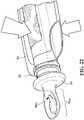
- the spout 20 of the spout pouch 14has two flanges - an upper flange 40a and a lower flange 40b.
- the two flangesare spaced apart, such that, when the spout 20 is snapped into the opening 38a in the holder, the upper flange 40a is above a top surface of the top 12a of the holder 12, and the lower flange 40b is below the top surface of the holder 12.
- the spout 20includes a feature 20a, such as a circumferential ridge, rib, boss, groove, or step, inside the spout 20 with which the connector 24 engages and helps hold the nipple 16 in place once it is coupled to the spout 20.
- Figs. 12 through 14show the assembly of the nipple 16 onto the spout pouch 14, the spout pouch 14 being held in the holder 12.
- the nipple 16may have a skirt 42 with a generally oblong shape.
- the connector 24gets pushed into the spout 20 of the spout pouch 14, forming a liquid-tight seal between the outer surface (or set of surfaces) of the connector 24 and the inner surface (or set of surfaces) of a feature connected to the spout 20.
- the axial bore 26passes from the end of the connector 24 through to the tip of the nipple 16, where it meets the nipple orifice 36. Once the nipple 16 is pushed into place into the spout 20, the contents of the pouch 14 can pass through the axial bore 26 of the nipple 16, through the orifice 36, and into the mouth of an infant.
- the nipple cover 18may be used to push the nipple 16 into the spout pouch 14.
- the nipple cover 18is used as a tool to push the nipple 16 into place, as the connector 24 is forced into the spout 20 of the spout pouch 14, while also protecting the nipple 16 from contamination during the nipple insertion process.
- the nipple cover 18may be lifted off, leaving the nipple 16 in place, securely coupled to the spout 20 and forming a liquid-tight seal with the spout 20. As such, the user's hands never come in direct contact with the nipple 16.
- Fig. 14shows the nipple 16 fully assembled into the spout 20 of the spout pouch 14 with the spout pouch 14 assembled to the holder 12.
- the skirt 42 of the nipple 16contacts a top surface of the top 12a of the holder once the connector 24 is coupled to the spout 20 of the spout pouch 14.
- the skirt 42 of the nipple 16 and the holder 12are both generally oblong in cross-sectional shape.
- the oblong shape of the skirt 42 of the nipple 16helps to create a more ergonomic shape, and a better seal between the nipple 16 and an infant's mouth.
- the cross-sectional shape of the skirt 42 of the nipple 16 and of the holder 12may be round, oval, or other polygonal shape with or without rounded corners.
- Figs. 15a-15d and 16show a one-piece feeding nipple having an oblong shape that is designed to be pushed into a spout pouch 14 for the purpose of feeding an infant.
- the nipple 16includes a connector 24 having a connector region 24a which is designed to be pushed into, and engage, the spout 20 of the spout pouch 14 to form a liquid-tight seal without the need for any additional rings or other hardware.
- the nipple 16also includes a tip region 44, which is meant to be inserted into the mouth of an infant.
- the nipple 16includes a skirt 42 having a lower region 46 that generally surrounds the connector 24 and connector region 24a and an abutment region 48 that abuts the tip region 44, such that the infant's lips meet the nipple 16 near the transition from the abutment region 48 to the lower region 46.
- the skirt 42may having a bottom end 42a that has a generally oblong shape, with the oblong shape having a long axis (along line L in Fig. 15d ) and a short axis (along line S in Fig. 15d ).
- the abutment region 48may have a textured surface, and there may be a shoulder 50 between the abutment region 48 and the lower region 46.
- the shoulder 50may be positioned at the approximate location of an infant's lips during feeding from the nipple.
- the shoulder 50may extend around the circumference of the nipple 16. This step may be advantageously positioned slightly outside the area where the connector 24 meets the underside of the skirt 42.
- the shoulder 50may be designed to provide an ergonomically or functionally favorable resting position for an infant's lips during feeding. The shoulder 50 may also help provide a better seal between an infant's lips and the nipple 16.
- the abutment region 48may have a stiffness greater than the stiffness of the lower region 46, (e.g., due to a greater thickness in the abutment region) in order to facilitate better latching or an ergonomically or functionally superior coupling between an infant's mouth and the nipple 16 toward the lower region 46.
- a stiffness greater than the stiffness of the lower region 46e.g., due to a greater thickness in the abutment region
- the shoulder 50 and the decrease in thickness described abovemay be combined.
- the skirt 42 of the nipple 16may be round, rather than oblong, in shape.
- the nipple 16may be advantageously made of a single piece of material. This has many advantages, primarily the simplicity of only having one piece to handle, store, clean, and install.
- Fig. 15bshows a front view of the long axis of the oblong shape of the skirt 42 of the nipple 16.
- Fig. 15cshows a side view of the short axis of the oblong skirt 42 of the nipple 16.
- Fig. 15dshows a top view of a one-piece feeding nipple with an orifice 36 at the tip of the nipple 16.
- the orifice 36may be in the shape of a slit, through which the pouch 14 contents pass into the infant's mouth.
- the slitmay be oriented transverse to the long axis of the oblong shape of the skirt 42 of the nipple, such as shown in Fig. 15d .
- the slit lengthdefines an axis, "the slit axis", along the short axis of the skirt 42, that is transverse to the long axis of the oblong nipple skirt 42.
- the slitmay open, allowing the flow of liquids, pastes, gels, or food through the slit.
- the slit axisis oriented such that it will run generally from top to bottom in an infant's mouth, meaning that natural up and down massaging motion of the infant's tongue can cause deformation along the slit axis, which can in turn cause the slit to open, allowing the contents of the pouch 14 to flow through the slit. Additionally, suction from the infant's mouth may cause or increase the flow of the pouch contents through the slit.
- the orifice in the tip region of the nipplemay be a hole.
- a slit in the nipplemay be a straight line, as described above, or it may be curved. A curved slit could be used to create different flow patterns or different flows based on different types of deformation of the tip region of the nipple.
- Fig. 16shows a cross-sectional view of a one-piece feeding nipple 16.
- the connector 24may include a connector region 24a, which can engage with a feature 20a in the spout 20 of the spout pouch 14, to help hold the nipple 16 in place (such as shown and discussed in Fig. 11b ).
- the connector region 24amay be a flange.
- the nipple 16, including the connector 24, the tip region 44 and the skirt 42may be made of a soft, compressible material, such as silicone or rubber.
- the connector 24may be frustro-conical in shape, with a round bore 26, and its outer diameter may be slightly larger than an inside diameter of the spout 20 of the spout pouch 14.
- the connector 24When the connector 24 is pushed into position inside the spout 20, the connector 24 deforms and pushes out against an inner surface of the spout 20.
- the connector 24forms a liquid-tight seal with the spout 20 of the spout pouch 14, much in the same way that a cork or stopper forms a liquid-tight seal with the inner surface of a mouth of a bottle.
- the spout 20 of the spout pouch 14may be made of a relatively soft, compressible material, such that the spout 20 deforms more than the connector 24 when the connector 24 is pushed into place.
- there is a featuree.g., a flange
- the spout 20includes a feature 20a, such as a circumferential ridge, boss, or groove, (e.g., as shown in Fig. 11b ) inside the spout 20 of the spout pouch 14 with which this connector feature engages to help hold the nipple 16 in place once it is coupled to the spout 20.
- this feature of the connector regionmay be a groove, a step, or other feature that could engage with the feature in the spout 20 of the spout pouch 14 to help hold the nipple 16 in place inside the spout 20.
- Fig. 16also shows the axial bore 26, which is open at the bottom end of the connector, and extends through the nipple 16. The axial bore 26 is coupled to the orifice 36 at the tip of the nipple 16. As such, pouch 14 contents can flow through the axial bore 26, through the orifice 36, and into the mouth of an infant.
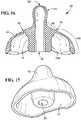
- Fig. 17shows the nipple 16 inside the nipple cover 18.
- a usermay grip the top of the nipple cover 18, never touching the nipple itself, and use the top of the nipple cover 18 as a tool to push the nipple 16 into place in or on the spout 20 of the spout pouch 14.
- Fig. 18shows a spout pouch 14 with an adapter 30 for fitting a conventional feeding nipple 52 and attachment ring 54 onto or into the spout pouch 14.
- Figs. 19a and 19bshow an oblong nipple 16 having a securing flange 16a at the bottom of the skirt 42 that may be secured onto or into a conventional bottle 56 using a standard attachment ring 54, e.g., lock ring.
- the attachment ring 54may attach to the top of a bottle 56 using a threaded connection.
- the nipple 16may have a securing flange 16a that connects to the bottom of the skirt 42 and extends outward, such that the flange 16a is pressed against a surface of the bottle when the attachment ring 54 is assembled to the bottle 56.
- the securing flange 16aforms a liquid-tight seal with a surface of the bottle 56, when the attachment ring 54 is tightened into place.
- the skirt 42 of the nipple 16 that contacts the infant's mouthmay be oblong in shape.
- the securing flange 16amay extend outward from the base of the skirt region to form a circle at its outer perimeter.
- the nipple 16includes of a tip region 44 connected to a generally oblong skirt 42, which is connected to a thin securing flange 16a that is generally circular at its outer edges.
- Figs. 20a and 20bshow an oblong nipple 16 having a connector 24 that is secured onto or into a conventional bottle 56 using a nipple adapter 58.
- the nipple adapter 58couples the nipple 16 to a container for feeding an infant.
- the nipple adapter 58has at least one generally cylindrical opening 60 through which liquid flows during feeding.
- the nipple adapter 58includes a first end 58a and second end 58b.
- the first end 58ais configured to be coupled to a nipple 16
- the second end 58bis configured to be coupled to an infant feeding container, e.g., conventional bottle 56.
- the nipple adapter 58may contain a spout-like feature on the first end 58a, with an opening configured to receive a connector 24 on the bottom of a nipple 16.
- Different adapters 58 of this sortwill allow connection of this type of nipple 16 to a wide range of different types of infant feeding containers 56.
- the first end 58a of the nipple adapter 58has an opening configured to receive a connector 24 of the type described above, while the second end 58b of the nipple adapter 58 has an internally threaded connection for coupling with a threaded baby bottle 56.
- the second end 58b of nipple adapter 58threads onto a baby bottle 56, and the nipple 16 with connector 24 can be pushed into the opening on the first end 58a of the nipple adapter 58, as described previously above.
- the first end 58a of the nipple adapter 58may have internal features as described previously for engaging features on the connector 24, to help hold the nipple in place relative to the nipple adapter 58.
- Figs. 21a and 21bshow two different feeding utensils 64 that may be connected to a spout pouch 14.
- Fig. 21ashows a feeding utensil 64 in the shape of a feeding spout
- Fig. 21bshows a feeding utensil 64 in the shape of a spoon.
- the feeding utensil 64includes a connector 66 with an axial bore 68 that is configured to connect to a container, such as a spout pouch 14 described above.
- the connector 66is similar, and functions in a similar manner, to the connector 24 with axial bore 26 shown and discussed above with respect to the nipple 16.
- the feeding utensil 64also includes a feeding region 64a configured to be placed in a mouth of a child.
- the feeding region 64ahas an opening 68a that is in communication with the axial bore 68 and which is configured to allow the liquid to flow from the container, e.g., spout pouch 14, through the axial bore 68, through the opening 68a and into or onto the feeding region 64a.
- the feeding utensil connector 66may be pushed into the spout 20 of the spout pouch 14, forming a liquid-tight seal between the outer surface (or set of surfaces) of the connector 66 and the inner surface (or set of surfaces) of the spout 20 or of a feature connected to the spout 20.
- the axial bore 68may pass from the end of the connector 66 through to the feeding region 64a of the feeding utensil 64.
- the contents of the pouch 14can pass through the axial bore 68 of the feeding utensil 64, through the opening 68a, onto the feeding region 64a (e.g., the spoon as shown in Figs. 21b and 22 ) or into the feeding region 64a (e.g., the feeding spout as shown in Fig. 21a ), and into the mouth of a child.
- the feeding region 64ae.g., the spoon as shown in Figs. 21b and 22
- the feeding region 64ae.g., the feeding spout as shown in Fig. 21a
- the connector 66may include a connector region 66a, which can engage with a feature 20a (such as shown and discussed in Fig. 11b ) in the spout 20 of the spout pouch 14, to help hold the feeding utensil 64 in place.
- the connector region 66amay be a flange.
- the feeding utensil 64(e.g., the feeding region 64a and/or the connector 66) may be made of a soft, compressible material, such as silicone or rubber. A soft, compressible material may provide the additional benefit of helping to create the liquid tight seal and providing a gentle feeding experience for a teething infant or child.
- the connector 66may be frustro-conical in shape, with a round bore 68, and its outer diameter may be slightly larger than an inside diameter of the spout 20 of the spout pouch 14.
- the connector 66When the connector 66 is pushed into position inside the spout 20, the connector 66 deforms and pushes out against an inner surface of the spout 20. As such, the connector 66 forms a liquid-tight seal with the spout 20 of the spout pouch 14, much in the same way that a cork or stopper forms a liquid-tight seal with the inner surface of a mouth of a bottle.
- the connector 66may fit on an outside surface of an opening in the spout 20 in order to form a liquid-tight seal with the spout 20.
- the connector 66may engage one or both of an internal surface of the spout 20 and an external surface of the spout 20.
- the spout 20 of the spout pouch 14may be made of a relatively soft, compressible material, such that the spout 20 deforms more than the connector 66 when the connector 66 is pushed into place.
- the spout 20includes a feature 20a, such as a circumferential ridge, boss, or groove, (e.g., as shown in Fig. 11b ) inside the spout 20 of the spout pouch 14 with which this connector feature engages to help hold the feeding utensil 64 in place once it is coupled to the spout 20.
- This featuremay be a groove, a step, or other feature that could engage with a feature in or on the spout 20 of the spout pouch 14 to help hold the feeding utensil 64 in place inside, or otherwise coupled to, the spout 20.
- the axial bore 68which is open at the bottom end of the connector 66, and extends through the feeding region 64a. As such, pouch 14 contents can flow through the axial bore 26, to the feeding region 64a, and into the mouth of a child.
- the feeding utensil 64may include a cover 70, similar to cover 18 discussed above.
- the spout pouch 14, nipple 16, feeding utensil 64, and adapter(s) 30may be part of a child feeding kit that allows the spout pouch 14 to be used with various types of feeding devices as well as a breast pump.
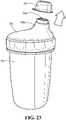
- a liquid storage container 72may be used, such as shown in Fig. 23 .
- the liquid storage container 72has a lid 74 that is removably coupled to the liquid storage container 72.
- the lid 74includes a lid opening 74a configured to engage with the spout 20 so as to allow the liquid to flow from the liquid storage container 72 to the spout pouch 14.
- the container 72may include a cover 76 that covers the lid opening 74a in the lid 74.
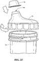
- the liquid storage container 72may be filled from a container 78 that holds the liquid, such as a blender, juicer, or larger storage container, as shown in Fig. 24 .
- a container 78that holds the liquid
- the lid 74is secured to the top of the container 72, and the cover 76 may be placed over the opening 74a, (e.g., for storage, transport, etc.), such as shown in Fig. 25 .
- the opening 74a of the liquid storage container 72is connected to the spout 20 of the spout pouch 14, as shown in Fig. 26 .
- the liquid storage container 72may be connected to the spout pouch by any number of mechanisms, e.g., inserted into, rested on top of, snap fit into or onto, a threaded connection, an interference fit, etc.
- the liquid storage container 72may be made from flexible materials that allow the container 72 to be readily squeezed so that the liquid contained therein is pushed out and into the spout pouch 14.
- the lid 74may include a spout 74b so that the container 72 may be easily connected to the spout pouch 14.
- the liquid storage container 72may be able to fill one or more spout pouches 14.
Landscapes
- Health & Medical Sciences (AREA)
- Life Sciences & Earth Sciences (AREA)
- Animal Behavior & Ethology (AREA)
- General Health & Medical Sciences (AREA)
- Public Health (AREA)
- Veterinary Medicine (AREA)
- Heart & Thoracic Surgery (AREA)
- Engineering & Computer Science (AREA)
- Pediatric Medicine (AREA)
- Vascular Medicine (AREA)
- Anesthesiology (AREA)
- Biomedical Technology (AREA)
- Hematology (AREA)
- Mechanical Engineering (AREA)
- Medical Preparation Storing Or Oral Administration Devices (AREA)
- Bag Frames (AREA)
Description
- The present invention relates to an infant feeding system.
- Traditionally, baby feeders have taken the form of a generally cylindrical bottle (typically, glass or plastic) and a removable nipple closing one end of the bottle. The nipple is commonly secured to the bottle by a threaded circular ring or collar having a central hole through which the nipple protrudes and which holds it securely to the bottle. An example is
U.S. Patent No. 8,113,364, issued Feb. 14, 2012 to Ladan Asadi . - In some feeders using rings or collars to secure the nipple, flexible liners are inserted inside a rigid bottle to hold the liquid contents. An example is
U.S. Patent No. 6,616,000, issued Sep. 9, 2003 to Charles Renz and assigned to Playtex Products, Inc. - Some baby feeders attach a removable nipple directly to a disposable feeder body. An example is
U.S. Patent Application Pub. No. 2012/0234790 A1 . - Many kinds of flexible, reclosable bags are known and used for food storage, including liquid foods, and some of these are used for receiving storing breast milk. One example is the Medela™ "pump and save"™ breastmilk bag. This bag is essentially a flat pouch closed on three sides but having a throat or opening extending the width of the bag on the top side through which the bag may be filled when opened. The bag is closed by forcing a rib along the top into a corresponding channel to form a friction seal. A separate feeder bottle is required for subsequent feeding of the contents.
- These systems all require significant handling during milk collection, storage, and preparation for feeding, and can unnecessarily expose the contents to contamination.
US 2002/0017528 discloses a drink spout system including a valve assembly to regulate the flow of the drink fluid through the drink spout and to prevent drink fluid from being unintentionally dispensed from the drink container when the drink container is pierced by the drink spout system or when the drink container is tipped over or dropped.US2011/0151069 discloses an infant feeding system comprising a sterile sealed laminated bag having a predetermined quantity of liquid infant food sealed therein, a compressed integral sterile teat sealed with the bag closure and/or spout and a protective cap for the teat, the system being arranged such that the cap can be removed to enable the infant to feed from the sterile teat and food.- According to a first aspect, there is provided an infant feeding system according to
claim 1. - Coupling the spout of the spout pouch to the breast pump may include coupling an adapter to the spout. The adapter may have a threaded end configured to mate with threads on the breast pump. The spout may have a cross-sectional area greater than about three square centimeters.
- The nipple includes a connector having an axial bore that is coupled to an orifice in the nipple, the connector forms a liquid tight seal with the spout of the spout pouch, and coupling the nipple to the spout includes inserting the connector into the spout. The connector may have an inlet region and the inlet region further includes a circumferentially disposed flange, the spout may include a feature configured to receive the flange, and coupling the nipple to the spout may include inserting the connector into the spout until the flange has engaged with the feature. The feature may be a recess or a ridge in the spout.
- The foregoing features of embodiments will be more readily understood by reference to the following detailed description, taken with reference to the accompanying drawings, in which:
Fig. 1 is a perspective view of an assembled infant feeding system including a holder, spout pouch, nipple (not visible), and nipple cover useful for understanding the present invention.Fig. 2 is an exploded view of an infant feeding system with a spout pouch (with cap) being assembled into a holder, along with a nipple and nipple cover useful for understanding the present invention.Fig. 3 is a perspective view of a cap being assembled on to a spout pouch useful for understanding of the present invention.Fig. 4 is an exploded, perspective view of a spout pouch being connected to a breast pump, using a threaded adapter useful for understanding the present invention.Fig. 5 is a perspective view of multiple adapters which may be used to couple a spout pouch to various breast pumps, for collecting breast milk. Additionally, these adapters may be used to couple feeding nipples to spout pouches, for the purpose of feeding an infant.Fig. 6 is a perspective view of a spout pouch with a cap assembled to form a liquid tight seal useful for understanding the present invention.Fig. 7 is an exploded perspective view showing a feeding nipple inside its case. The top of the case is a cover for the nipple and holder, when the nipple is removably coupled to the spout pouch, and the spout pouch is removably coupled to the holder.Fig. 8 is a perspective view showing the nipple assembled to the spout pouch, for the purpose of feeding an infant useful for understanding the present invention.Fig. 9 is a perspective view of an exemplary holder for a spout pouch for use in embodiments of the present invention.Fig. 10a is a perspective view andFig. 10b is a rear view showing the spout pouch assembled to the holder according to embodiments of the present invention.Fig. 11a is a close-up, perspective view andFig. 11b is a cross-sectional view showing a snap fit between the spout of the spout pouch and the holder according to embodiments of the present invention.Fig. 12 is a perspective view showing the assembly of the nipple onto the spout pouch, the spout pouch being held in the holder useful for understanding the present invention.Fig. 13 is a perspective view showing the top of the nipple case being used to push the nipple into the spout pouch useful for understanding the present invention.Fig. 14 is a perspective view of an assembled spout pouch, nipple, and holder useful for understanding the present invention.Figs. 15a-15d show a one-piece feeding nipple having an oblong shape according to embodiments of the present invention.Fig. 15a shows a perspective view of the bottom,Figs. 15b and15c show side front and side views, respectively, andFig. 15d shows a top view of the one-piece feeding nipple.Fig. 15d shows a slit at the tip of the nipple, through which the pouch contents pass into the infant's mouth.Fig. 16 is a cross-sectional view of a one-piece feeding nipple having an oblong shape that is designed to be pushed into a spout pouch for the purpose of feeding an infant according to embodiments of the present invention. This figure shows in detail the connector, which gets pushed into the spout of the spout pouch. It also shows the flange on the connector, which can engage with a feature in the spout of the spout pouch, to help hold the nipple in place.Fig. 17 is a perspective, bottom view showing the nipple inside the nipple cover according to embodiments of the present invention.Fig. 18 is an exploded view of a spout pouch with an adapter for fitting a conventional feeding nipple and ring onto the spout pouch useful for understanding the present invention.Figs. 19a and19b show an exploded view and an assembled view, respectively, of an oblong nipple having a securing flange secured onto a conventional bottle useful for understanding the present invention.Figs. 20a and20b show an exploded view and an assembled view, respectively, of an oblong nipple secured onto a conventional bottle using a nipple adapter useful for understanding the present invention.Figs. 21a and 21b show an exploded, perspective view of various feeding devices being connected to a spout pouch.Fig. 22 shows a perspective view of a feeding utensil in the shape of a spoon connected to a spout pouch.Fig. 23 shows a perspective view of a liquid storage container configured to engage with a spout pouch useful for understanding the present invention.Fig. 24 shows a liquid storage container being filled with liquid from another device useful for understanding the present invention.Fig. 25 shows a liquid storage container lid with a lid opening useful for understanding the present invention.Fig. 26 shows a liquid storage container connected with a spout pouch useful for understanding the present invention.- Definitions. As used in this description and the accompanying claims, the following terms shall have the meanings indicated, unless the context otherwise requires:
- A "spout pouch" is a flexible pouch to which is affixed a spout that is configured to receive a cap; the cap alone can be coupled, without use of other hardware, to the spout of the spout pouch.
- A "feeding spout" is a spout that is configured to be placed within the mouth and to be affixed to a spout pouch.
- A "cap" for a spout pouch is a single-piece component.
- A spout that is "substantially rigid" is a spout that retains shape sufficiently so that the spout can be readily coupled to another member, to form a liquid tight seal, without use of any additional hardware.
- A "liquid" includes any of breast milk, formula, milk, juice, and pureed food.
- "Expressed breast milk" includes breast milk that has been pumped, collected extracted or gathered.
- A "nipple" is a feeding appliance for an infant, wherein a portion of the appliance is coupled to a container of liquid and a tip region of the appliance is configured to be placed in a mouth of the infant so that the liquid can flow from the container into the mouth of the infant.
- An "orifice" in a nipple includes a slit, a hole, or a combination of both, through which liquid emerges into the mouth of an infant using the nipple to ingest the liquid.
- A "slit" in a nipple is an orifice created without the removal of material in the nipple, so that opposing walls of the nipple defining the slit are in contact with one another over their entire length when the nipple is not deformed. For example, a slit is formed when a knife is used to pierce through a layer of material, and is moved through the material, cutting the material but not removing any material from the original shape. A slit may be straight or curved.
Fig. 1 is a perspective view of an assembledinfant feeding system 10. Theinfant feeding system 10 may include aholder 12, aspout pouch 14, a nipple 16 (shown inFig. 2 ), and acover 18. Thespout pouch 14 snaps into theholder 12. A rigid spout 20 (described in more detail below) snaps into a feature on theholder 12, after being forced through a narrow gap in theholder 12. Thespout pouch 14 may be inserted into theholder 12 by passing through openings either in the bottom, sides, front, and/or back of theholder 12. Thecover 18, which also serves as the top of a nipple case (shown and described in more detail below inFig. 7 ), attaches to the nipple 16 (which is inserted into the spout of the spout pouch), or it may attach to theholder 12. Thecover 18 may be coupled to thenipple 16 orholder 12 by any of a friction fit, a snap fit, a magnetic coupling, a connection that requires a twisting action, or other type of connection.Fig. 2 is an exploded view of theinfant feeding system 10 with thespout pouch 14 andcap 22 being assembled into theholder 12, and anipple 16 andnipple cover 18. Thespout pouch 14 has aspout 20 that is configured to snap fit into theholder 12. Theholder 12 may be a thin-walled plastic shell, designed to hold the generallyrigid spout 20 of thespout pouch 14. The connection between thespout 20 andholder 12 may be any of a friction fit, a snap fit, a magnetic coupling, a connection that requires a twisting action, or other type of connection. On one embodiment, thenipple 16 is oblong in shape, for the purpose of a more ergonomic connection with an infant's mouth. Thenipple 16 connects to thespout 20 of thespout pouch 14 by a connector 24 (shown in more detail inFigs. 15a-15d ) on the bottom of thenipple 16. Theconnector 24 has ahollow bore 26, through which liquids, foods, pastes, or gels pass from the pouch into the infant's mouth. In use, theconnector 24 is pushed into the opening of thespout 20, creating a liquid-tight connection between theconnector 24 and thespout 20. Theconnector 24 may be slightly larger in size than the opening of thespout 20, but theconnector 24 may be made of a compressible material, so it may be forced into the opening of thespout 20. In one embodiment, thenipple 16 is a single piece, made of a single material.Fig. 3 is a perspective view of acap 22 being assembled on to aspout pouch 14. Thespout 20 of thespout pouch 14 may be made of a generally rigid material, and is configured to receive acap 22 capable of forming a water tight seal. In one embodiment, thecap 22 may be threaded, having helical features which interact with features on thespout 20, causing thecap 22 to form a liquid-tight seal with the spout when thecap 22 is twisted relative to thespout 20. In other embodiments, thecap 22 may be pressed, pulled, or twisted into place onto thespout 20. In other embodiments, the connection between thecap 22 and spout 20 may be an interference fit (e.g., where two or more elements are forced together, causing the materials to deform at their interface), a friction fit (e.g., where the cap is held to the spout by friction), a snap fit, or a latch fit (e.g., where a pressing, pulling, twisting action is required to secure the cap to the spout). In one embodiment, thepouch 14 material is a thin, flexible plastic film, and thespout 20 is a thicker, more rigid plastic material.Fig. 4 is an exploded, perspective view of aspout pouch 14 being connected to one end of abreast pump 28, using a threadedadapter 30. In use, the adapter is coupled to thespout 20 of thespout pouch 14, and the end of thebreast pump 28 is coupled to theadapter 30. The breast pump is then operated to express breast milk into thespout pouch 14 so that thespout pouch 14 collects the expressed breast milk. In one embodiment, thespout pouch 14 is configured to receive the breast milk that is pumped from a woman's breast by a breast pump. In order to attach to multiple different pumps available on the market, various types of adapters, such as shown inFig. 5 , may be provided to couple thespout 20 of thespout pouch 14 to the end of abreast pump 28. In other embodiments, the connection betweenadapter 30 andspout pouch 14 may be any of an interference fit, a friction fit, a snap fit, or a latch fit. Similarly, the connection between adapter and breast pump may be any of an interference fit, a friction fit, a snap fit, or a latch fit. Connecting theadapter 30 to the end of thebreast pump 28, or connecting theadapter 30 to thespout 20 of thespout pouch 14 may require any of (or any combination of) twisting, pushing, pulling, or squeezing. In yet another embodiment, thespout 20 may couple directly to the outlet of abreast pump 28, by any of the means listed above, without the need for an adapter. Thespout pouch 14 may be held in aholder 12 while thespout pouch 14 is coupled to the adapter, or to a breast pump, or both. Aholder 12 may be used to provide a stable base for holding thespout pouch 14 during and after collecting milk using a breast pump. Theholder 12, and its connection to thespout pouch 14, are described further below.Fig. 5 shows multiple adapters which may be used to couplespout pouches 14 to breast pumps, for collecting breast milk. Additionally, in examples not belonging to the invention, theseadapters 30 may be used to couple feeding nipples to spout pouches, for the purpose of feeding an infant. Since there are multiple different brands of breast pumps, there are many different types of connections required to couple thespout pouches 14 to theoutlets 28 of a variety of breast pumps available on the market. Different adapters may be provided, with different types of connections, for coupling to a wide range of breast pumps for collection of pumped breast milk. These connections may include any of a threaded connection, an interference fit, a friction fit, a snap fit, or a latch fit. The other side of the adapter is coupled to the spout of the spout pouch, to allow liquid to flow into the pouch. The types of connections between the adapter and the nipple may be any of the connection types listed above. Typically, the connection between the adapter and the nipple will be a threaded connection. In some cases, theadapter 30 used to couple a breast pump to the spout pouch may be the same adapter that is used to couple a feeding nipple to the spout pouch. In some examples, an infant can be fed using only thespout pouch 14 and anipple 16. In other examples, a spout pouch, an adapter, and a nipple may be used. Aholder 12 is used to hold the spout pouch during feeding, in conjunction with either an adapter and a nipple or a nipple alone.Fig. 6 shows aspout pouch 14 withcap 22 assembled to form a liquid tight seal. The spout is coupled to the pouch to form a liquid-tight vessel, designed for holding liquids or foods for infant or child feeding. An infant or child may feed directly from the pouch, either by passing the liquid from the pouch, through the spout into the infant's mouth (directly or indirectly), or the pouch may be used for storage only, and the contents may be transferred to another container for feeding. For direct feeding, different feeding devices may be used in conjunction with the spout pouch. Various nipples, valves, openings, spoons, feeding spouts, and other devices for interfacing with an infant's or child's mouth may be connected to the spout of the spout pouch. Various types of connections may be used for coupling these feeding devices to the spout. Examples of such connections are: threaded connections, an interference fit (e.g., where two or more elements are forced together, causing the materials to deform at their interface), a friction fit (e.g., where the feeding device is held to the spout by friction), a snap fit (e.g., such as described below with the nipple and feeding utensil connectors), or a latch fit (e.g., where a pressing, pulling, twisting action is required to secure the feeding device to the spout). Examples of feeding devices are: nipples, perforated containers, openings, spoons, feeding spouts, and valves. Optionally, an infant or child could feed directly from the pouch without a feeding device attached - the infant or child could simply pour or suck the contents of the pouch through the pouch and into his or her mouth. Similarly, a spoon, a fork, a straw, or other utensil may be passed through the spout in order to pick up and remove contents of the pouch for feeding. The connection between the cap and spout may be any of the types of connections listed previously. Preferably, thespout 20 has a cross-sectional area greater than about three square centimeters.Fig. 7 is an exploded view showing a feeding nipple inside itscase 32. Theinfant nipple case 32 includes anipple cover 18 and a base 34 that cover and protect anipple 16. Thecase 32 components serve three purposes. 1) Thenipple cover 18 andbase 34 of thecase 32 combine to form a protective case for thenipple 16; 2) thenipple cover 18 of the case can be used as a cover for thenipple 16 when thenipple 16 is assembled to thespout pouch 14, and thespout pouch 14 is assembled to theholder 12; and 3) thenipple cover 18 of the case can be used as a tool to push thenipple 16 into thespout 20 of thespout pouch 14, avoiding the necessity of the user touching thenipple 16 directly with his or her hands and potentially contaminating it.Fig. 8 is a perspective view showing thenipple 16 assembled to thespout pouch 14, for the purpose of feeding an infant. This figure shows thenipple 16 pushed into thespout 20 of the spout pouch14. Thenipple 16 is pushed into thespout 20 of thespout pouch 14, and an infant could be fed directly from thespout pouch 14. Liquids contained within thespout pouch 14 would flow through thespout 20 andnipple 16, through anorifice 36 in the nipple 16 (described in more detail below inFigs. 15a-15d ), into the infant's mouth. Thespout pouch 14 is held in a holder 12 (described in more detail inFigs. 10a-11b ). Thespout pouch 14 may be held in aholder 12, and anipple cover 18 may be used to cover thenipple 16 to protect it from contamination (as described above inFig. 7 ). In one embodiment, the nipple (including a liquid-tight connector for connection to the spout 20) is made of a single piece of material. In other embodiments, the nipple and its connector may be made of multiple components (as described in more detail below inFigs. 19a-19b ).Fig. 9 is a perspective view of aholder 12 for aspout pouch 14 according to embodiments of the present invention. Theholder 12 may be a thin-walled plastic shell, with openings on the top 12a, bottom 12b, front 12c, and/or back 12d of the holder. Theopening 38a on the top 12a of the holder may be a C-shaped opening that is configured to receive a portion of thespout 20 of thespout pouch 14, so as to couple thespout 20 to theholder 12 by way of a snap fit configuration, although other shaped top openings may also be used. The snap fit configuration will be described in more detail below. In addition, theholder 12 may have anopening 38b in the bottom 12b of theholder 12, anopening 38c in the front 12c of theholder 12, and/or anopening 38d in the back 12d of theholder 12. These openings can be used for any of inserting thepouch 14 into the holder; squeezing thepouch 14 to push gas, liquid, or food out of thepouch 14; or for gripping theholder 12. For example, twolarge openings holder 12 may provide gripping surfaces for a two-handed grip for an infant, as well as providing multiple other gripping options for adults or infants.Figs. 10a and10b show thespout pouch 14 assembled to theholder 12 using a snap fit configuration between thespout 20 and theopening 38a in the top 12a of theholder 12. During assembly, thespout 20 is inserted into thetop opening 12a of theholder 12 in a snap fit configuration. Theopening 38a may be C-shaped and may have a narrow "mouth" through which a portion of thespout 20 must be passed. The width of the C-shapedopening 38a is smaller than a dimension of a portion of thespout 20, such that the passing of the portion of the spout through the "mouth" of the C-shaped opening causes thespout 20 to be substantially held in place. In other embodiments, theholder 12 may have thicker walls, walls of non-uniform thickness, and/or may be constructed of flexible materials.- As shown in
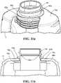
Fig. 10b , theholder 12 may rest on a flat surface without thepouch 14 contacting that surface, as a result of thepouch 14 being substantially shorter than holder. As mentioned previously, thecap 22 may be placed on thespout 20 of thespout pouch 14. Thecap 22 may be threaded onto thespout 20 of thespout pouch 14, forming a liquid-tight seal between thecap 22 and thespout 20. As shown, thespout 20 andspout pouch 14 can be coupled to theholder 12 with thecap 22 of thespout pouch 14 coupled to thespout 20, so as to ensure the contents of thepouch 14 are not spilled during installation of thepouch 14 into theholder 12. - As shown in more detail in
Figs. 11a and 11b , the coupling between thespout 20 and theholder 12 is a snap fit as described above. Thespout 20 of thespout pouch 14 has two flanges - anupper flange 40a and alower flange 40b. The two flanges are spaced apart, such that, when thespout 20 is snapped into theopening 38a in the holder, theupper flange 40a is above a top surface of the top 12a of theholder 12, and thelower flange 40b is below the top surface of theholder 12. With this type of configuration, theflanges spout 20 andpouch 14 within theholder 14, along the longitudinal axis of thespout 20. Thespout 20 includes afeature 20a, such as a circumferential ridge, rib, boss, groove, or step, inside thespout 20 with which theconnector 24 engages and helps hold thenipple 16 in place once it is coupled to thespout 20. Figs. 12 through 14 show the assembly of thenipple 16 onto thespout pouch 14, thespout pouch 14 being held in theholder 12. As described in more detail inFigs. 15a-15d , thenipple 16 may have askirt 42 with a generally oblong shape. On the underside of thenipple 16, there is aconnector 24 with anaxial bore 26, as shown inFig. 12 . During the nipple insertion process, theconnector 24 gets pushed into thespout 20 of thespout pouch 14, forming a liquid-tight seal between the outer surface (or set of surfaces) of theconnector 24 and the inner surface (or set of surfaces) of a feature connected to thespout 20. The axial bore 26 passes from the end of theconnector 24 through to the tip of thenipple 16, where it meets thenipple orifice 36. Once thenipple 16 is pushed into place into thespout 20, the contents of thepouch 14 can pass through theaxial bore 26 of thenipple 16, through theorifice 36, and into the mouth of an infant.- As shown in
Fig. 13 , thenipple cover 18 may be used to push thenipple 16 into thespout pouch 14. In this case, thenipple cover 18 is used as a tool to push thenipple 16 into place, as theconnector 24 is forced into thespout 20 of thespout pouch 14, while also protecting thenipple 16 from contamination during the nipple insertion process. Once thenipple 16 is securely in place (e.g., once theconnector 24 is securely in place inside thespout 20 of the spout pouch 14), thenipple cover 18 may be lifted off, leaving thenipple 16 in place, securely coupled to thespout 20 and forming a liquid-tight seal with thespout 20. As such, the user's hands never come in direct contact with thenipple 16. Fig. 14 shows thenipple 16 fully assembled into thespout 20 of thespout pouch 14 with thespout pouch 14 assembled to theholder 12. As shown, theskirt 42 of thenipple 16 contacts a top surface of the top 12a of the holder once theconnector 24 is coupled to thespout 20 of thespout pouch 14. In one embodiment, theskirt 42 of thenipple 16 and theholder 12 are both generally oblong in cross-sectional shape. The oblong shape of theskirt 42 of thenipple 16 helps to create a more ergonomic shape, and a better seal between thenipple 16 and an infant's mouth. In other embodiments, the cross-sectional shape of theskirt 42 of thenipple 16 and of theholder 12 may be round, oval, or other polygonal shape with or without rounded corners.Figs. 15a-15d and16 show a one-piece feeding nipple having an oblong shape that is designed to be pushed into aspout pouch 14 for the purpose of feeding an infant. As shown, thenipple 16 includes aconnector 24 having aconnector region 24a which is designed to be pushed into, and engage, thespout 20 of thespout pouch 14 to form a liquid-tight seal without the need for any additional rings or other hardware. Thenipple 16 also includes atip region 44, which is meant to be inserted into the mouth of an infant. In addition, thenipple 16 includes askirt 42 having alower region 46 that generally surrounds theconnector 24 andconnector region 24a and anabutment region 48 that abuts thetip region 44, such that the infant's lips meet thenipple 16 near the transition from theabutment region 48 to thelower region 46. Theskirt 42 may having abottom end 42a that has a generally oblong shape, with the oblong shape having a long axis (along line L inFig. 15d ) and a short axis (along line S inFig. 15d ). Theabutment region 48 may have a textured surface, and there may be ashoulder 50 between theabutment region 48 and thelower region 46.- For example, there may be a slight "step" or raised area of material near where the
tip region 44 connects to theskirt 42 along theabutment region 48. Theshoulder 50 may be positioned at the approximate location of an infant's lips during feeding from the nipple. Theshoulder 50 may extend around the circumference of thenipple 16. This step may be advantageously positioned slightly outside the area where theconnector 24 meets the underside of theskirt 42. Theshoulder 50 may be designed to provide an ergonomically or functionally favorable resting position for an infant's lips during feeding. Theshoulder 50 may also help provide a better seal between an infant's lips and thenipple 16. Theabutment region 48 may have a stiffness greater than the stiffness of thelower region 46, (e.g., due to a greater thickness in the abutment region) in order to facilitate better latching or an ergonomically or functionally superior coupling between an infant's mouth and thenipple 16 toward thelower region 46. For example, there may be a decrease in thickness of the material in thelower region 46 where an infant's lips may be positioned during feeding. Such a decrease in thickness may cause a decrease in stiffness of the material at that location. This decrease in stiffness, or increase in apparent softness may help provide an ergonomically or functionally favorable resting position for an infant's lips during feeding. This decrease in stiffness may also help provide a better seal between an infant's lips and the nipple. In some embodiments, theshoulder 50 and the decrease in thickness described above may be combined. In some embodiments, theskirt 42 of thenipple 16 may be round, rather than oblong, in shape. In one embodiment, thenipple 16 may be advantageously made of a single piece of material. This has many advantages, primarily the simplicity of only having one piece to handle, store, clean, and install. Fig. 15b shows a front view of the long axis of the oblong shape of theskirt 42 of thenipple 16.Fig. 15c shows a side view of the short axis of theoblong skirt 42 of thenipple 16.Fig. 15d shows a top view of a one-piece feeding nipple with anorifice 36 at the tip of thenipple 16. Theorifice 36 may be in the shape of a slit, through which thepouch 14 contents pass into the infant's mouth. In one embodiment, the slit may be oriented transverse to the long axis of the oblong shape of theskirt 42 of the nipple, such as shown inFig. 15d . The slit length defines an axis, "the slit axis", along the short axis of theskirt 42, that is transverse to the long axis of theoblong nipple skirt 42. When thetip region 44 of thenipple 16 is compressed in the direction of the slit axis, the slit may open, allowing the flow of liquids, pastes, gels, or food through the slit. The slit axis is oriented such that it will run generally from top to bottom in an infant's mouth, meaning that natural up and down massaging motion of the infant's tongue can cause deformation along the slit axis, which can in turn cause the slit to open, allowing the contents of thepouch 14 to flow through the slit. Additionally, suction from the infant's mouth may cause or increase the flow of the pouch contents through the slit. In other embodiments, the orifice in the tip region of the nipple may be a hole. A slit in the nipple may be a straight line, as described above, or it may be curved. A curved slit could be used to create different flow patterns or different flows based on different types of deformation of the tip region of the nipple.Fig. 16 shows a cross-sectional view of a one-piece feeding nipple 16. As shown, theconnector 24 may include aconnector region 24a, which can engage with afeature 20a in thespout 20 of thespout pouch 14, to help hold thenipple 16 in place (such as shown and discussed inFig. 11b ). Theconnector region 24a may be a flange. In one embodiment, thenipple 16, including theconnector 24, thetip region 44 and theskirt 42, may be made of a soft, compressible material, such as silicone or rubber. In one embodiment, theconnector 24 may be frustro-conical in shape, with around bore 26, and its outer diameter may be slightly larger than an inside diameter of thespout 20 of thespout pouch 14. When theconnector 24 is pushed into position inside thespout 20, theconnector 24 deforms and pushes out against an inner surface of thespout 20. As such, theconnector 24 forms a liquid-tight seal with thespout 20 of thespout pouch 14, much in the same way that a cork or stopper forms a liquid-tight seal with the inner surface of a mouth of a bottle. In some embodiments, thespout 20 of thespout pouch 14 may be made of a relatively soft, compressible material, such that thespout 20 deforms more than theconnector 24 when theconnector 24 is pushed into place. In one embodiment, there is a feature (e.g., a flange) that extends around the circumference of theconnector 24 in theconnector region 24a. Thespout 20 includes afeature 20a, such as a circumferential ridge, boss, or groove, (e.g., as shown inFig. 11b ) inside thespout 20 of thespout pouch 14 with which this connector feature engages to help hold thenipple 16 in place once it is coupled to thespout 20. In one embodiment, this feature of the connector region may be a groove, a step, or other feature that could engage with the feature in thespout 20 of thespout pouch 14 to help hold thenipple 16 in place inside thespout 20.Fig. 16 also shows theaxial bore 26, which is open at the bottom end of the connector, and extends through thenipple 16. Theaxial bore 26 is coupled to theorifice 36 at the tip of thenipple 16. As such,pouch 14 contents can flow through theaxial bore 26, through theorifice 36, and into the mouth of an infant.Fig. 17 shows thenipple 16 inside thenipple cover 18. As stated above, a user may grip the top of thenipple cover 18, never touching the nipple itself, and use the top of thenipple cover 18 as a tool to push thenipple 16 into place in or on thespout 20 of thespout pouch 14.Fig. 18 shows aspout pouch 14 with anadapter 30 for fitting aconventional feeding nipple 52 andattachment ring 54 onto or into thespout pouch 14.Figs. 19a and19b show anoblong nipple 16 having a securingflange 16a at the bottom of theskirt 42 that may be secured onto or into aconventional bottle 56 using astandard attachment ring 54, e.g., lock ring. As shown, theattachment ring 54 may attach to the top of abottle 56 using a threaded connection. Thenipple 16 may have a securingflange 16a that connects to the bottom of theskirt 42 and extends outward, such that theflange 16a is pressed against a surface of the bottle when theattachment ring 54 is assembled to thebottle 56. The securingflange 16a forms a liquid-tight seal with a surface of thebottle 56, when theattachment ring 54 is tightened into place. Theskirt 42 of thenipple 16 that contacts the infant's mouth may be oblong in shape. The securingflange 16a may extend outward from the base of the skirt region to form a circle at its outer perimeter. For example, thenipple 16 includes of atip region 44 connected to a generally oblongskirt 42, which is connected to athin securing flange 16a that is generally circular at its outer edges.Figs. 20a and20b show anoblong nipple 16 having aconnector 24 that is secured onto or into aconventional bottle 56 using anipple adapter 58. As shown, thenipple adapter 58 couples thenipple 16 to a container for feeding an infant. Thenipple adapter 58 has at least one generallycylindrical opening 60 through which liquid flows during feeding. Thenipple adapter 58 includes afirst end 58a andsecond end 58b. Thefirst end 58a is configured to be coupled to anipple 16, and thesecond end 58b is configured to be coupled to an infant feeding container, e.g.,conventional bottle 56. Thenipple adapter 58 may contain a spout-like feature on thefirst end 58a, with an opening configured to receive aconnector 24 on the bottom of anipple 16. On thesecond end 58b of thenipple adapter 58, there are threads (not shown) for coupling thenipple adapter 58 to acontainer 56 for feeding an infant.Different adapters 58 of this sort will allow connection of this type ofnipple 16 to a wide range of different types ofinfant feeding containers 56. Thefirst end 58a of thenipple adapter 58 has an opening configured to receive aconnector 24 of the type described above, while thesecond end 58b of thenipple adapter 58 has an internally threaded connection for coupling with a threadedbaby bottle 56. As such, thesecond end 58b ofnipple adapter 58 threads onto ababy bottle 56, and thenipple 16 withconnector 24 can be pushed into the opening on thefirst end 58a of thenipple adapter 58, as described previously above. Thefirst end 58a of thenipple adapter 58 may have internal features as described previously for engaging features on theconnector 24, to help hold the nipple in place relative to thenipple adapter 58. A wide variety of bottle types exist, so there may be several different types of connections and threads that can be used on thesecond end 58b of thenipple adapter 58 for coupling tofeeding bottles 56. There may be external threads on thefirst end 58a of thenipple adapter 58, configured to receive acap 22.Figs. 21a and 21b show twodifferent feeding utensils 64 that may be connected to aspout pouch 14.Fig. 21a shows a feedingutensil 64 in the shape of a feeding spout, andFig. 21b shows a feedingutensil 64 in the shape of a spoon. The feedingutensil 64 includes aconnector 66 with anaxial bore 68 that is configured to connect to a container, such as aspout pouch 14 described above. Theconnector 66 is similar, and functions in a similar manner, to theconnector 24 withaxial bore 26 shown and discussed above with respect to thenipple 16. The feedingutensil 64 also includes afeeding region 64a configured to be placed in a mouth of a child. Thefeeding region 64a has anopening 68a that is in communication with theaxial bore 68 and which is configured to allow the liquid to flow from the container, e.g., spoutpouch 14, through theaxial bore 68, through theopening 68a and into or onto thefeeding region 64a.- During the feeding utensil insertion process, the feeding
utensil connector 66 may be pushed into thespout 20 of thespout pouch 14, forming a liquid-tight seal between the outer surface (or set of surfaces) of theconnector 66 and the inner surface (or set of surfaces) of thespout 20 or of a feature connected to thespout 20. Theaxial bore 68 may pass from the end of theconnector 66 through to thefeeding region 64a of the feedingutensil 64. Once the feedingutensil 64 is pushed into place onto or into thespout 20, the contents of thepouch 14 can pass through theaxial bore 68 of the feedingutensil 64, through theopening 68a, onto thefeeding region 64a (e.g., the spoon as shown inFigs. 21b and22 ) or into thefeeding region 64a (e.g., the feeding spout as shown inFig. 21a ), and into the mouth of a child. - As discussed above in connection with the
nipple 16, theconnector 66 may include aconnector region 66a, which can engage with afeature 20a (such as shown and discussed inFig. 11b ) in thespout 20 of thespout pouch 14, to help hold the feedingutensil 64 in place. Theconnector region 66a may be a flange. The feeding utensil 64 (e.g., thefeeding region 64a and/or the connector 66) may be made of a soft, compressible material, such as silicone or rubber. A soft, compressible material may provide the additional benefit of helping to create the liquid tight seal and providing a gentle feeding experience for a teething infant or child. Theconnector 66 may be frustro-conical in shape, with around bore 68, and its outer diameter may be slightly larger than an inside diameter of thespout 20 of thespout pouch 14. When theconnector 66 is pushed into position inside thespout 20, theconnector 66 deforms and pushes out against an inner surface of thespout 20. As such, theconnector 66 forms a liquid-tight seal with thespout 20 of thespout pouch 14, much in the same way that a cork or stopper forms a liquid-tight seal with the inner surface of a mouth of a bottle. Alternatively, theconnector 66 may fit on an outside surface of an opening in thespout 20 in order to form a liquid-tight seal with thespout 20. For example, theconnector 66 may engage one or both of an internal surface of thespout 20 and an external surface of thespout 20. Thespout 20 of thespout pouch 14 may be made of a relatively soft, compressible material, such that thespout 20 deforms more than theconnector 66 when theconnector 66 is pushed into place. There may be a feature (e.g., a flange) that extends around the circumference of theconnector 66 in theconnector region 66a. Thespout 20 includes afeature 20a, such as a circumferential ridge, boss, or groove, (e.g., as shown inFig. 11b ) inside thespout 20 of thespout pouch 14 with which this connector feature engages to help hold the feedingutensil 64 in place once it is coupled to thespout 20. This feature may be a groove, a step, or other feature that could engage with a feature in or on thespout 20 of thespout pouch 14 to help hold the feedingutensil 64 in place inside, or otherwise coupled to, thespout 20. Theaxial bore 68, which is open at the bottom end of theconnector 66, and extends through thefeeding region 64a. As such,pouch 14 contents can flow through theaxial bore 26, to thefeeding region 64a, and into the mouth of a child. The feedingutensil 64 may include acover 70, similar to cover 18 discussed above. - The
spout pouch 14,nipple 16, feedingutensil 64, and adapter(s) 30 may be part of a child feeding kit that allows thespout pouch 14 to be used with various types of feeding devices as well as a breast pump. In order to fill thespout pouch 14, (e.g., with liquids such as pureed food), aliquid storage container 72 may be used, such as shown inFig. 23 . As shown, theliquid storage container 72 has alid 74 that is removably coupled to theliquid storage container 72. Thelid 74 includes alid opening 74a configured to engage with thespout 20 so as to allow the liquid to flow from theliquid storage container 72 to thespout pouch 14. Thecontainer 72 may include acover 76 that covers thelid opening 74a in thelid 74. - In use, the
liquid storage container 72 may be filled from acontainer 78 that holds the liquid, such as a blender, juicer, or larger storage container, as shown inFig. 24 . Once theliquid storage container 72 is filled with the desired amount of liquid from thecontainer 78, thelid 74 is secured to the top of thecontainer 72, and thecover 76 may be placed over theopening 74a, (e.g., for storage, transport, etc.), such as shown inFig. 25 . To fill thespout pouch 14, theopening 74a of theliquid storage container 72 is connected to thespout 20 of thespout pouch 14, as shown inFig. 26 . Theliquid storage container 72 may be connected to the spout pouch by any number of mechanisms, e.g., inserted into, rested on top of, snap fit into or onto, a threaded connection, an interference fit, etc. Theliquid storage container 72 may be made from flexible materials that allow thecontainer 72 to be readily squeezed so that the liquid contained therein is pushed out and into thespout pouch 14. Thelid 74 may include aspout 74b so that thecontainer 72 may be easily connected to thespout pouch 14. Theliquid storage container 72 may be able to fill one ormore spout pouches 14.
Claims (4)
- An infant feeding system comprising:a nipple (16) formed of a deformable material, the nipple comprising:a connector (24) configured to be coupled to a container of liquid, wherein (i) the container is a spout pouch having an opening, (ii) the connector includes a connector region configured to engage with the opening of the spout pouch so as to form a liquid tight seal with the opening without need for additional hardware, and (iii) the connector includes an axial bore; anda tip region (44) configured to be placed in a mouth of an infant, the tip region having an orifice (36) in communication with the axial bore, so that the liquid can flow from the container through the axial bore and the orifice into the mouth of the infant;the spout pouch having a spout (20) and a pouch (14), wherein the connector of the nipple is configured to engage with the spout so as to form the liquid tight seal with the spout without the need for additional hardware, the spout having (i) a longitudinal axis through a center of the spout and (ii) an inner surface that includes a feature (20a) selected from the group consisting of a ridge, rib, boss, recess, groove and step, the feature configured to engage with the connector when the connector is inserted into the spout; and the pouch (14) comprising flexible material coupled to the spout, the pouch configured to hold the liquid; anda holder (12) having a top (12a) and a body, wherein the top of the holder has an opening (38a) configured to removably receive and snap fit to the spout and the body has an interior configured to receive the spout pouch, the spout having an outer surface with two flanges (40a, 40b) that are spaced apart such that an upper flange (40a) is above the top of the holder, and a lower flange (40b) is below the top of the holder 12, the flanges (40a, 40b) configured to prevent movement of the spout and pouch within the holder along the longitudinal axis of the spout.
- An infant feeding system according to claim 1, further comprising:
a nipple cover (18) configured to cover the nipple. - An infant feeding system according to claim 2, wherein the nipple cover is further configured to releasably engage with the nipple.
- An infant feeding system according to claim 1, further comprising:
a threaded cap (22) configured to cover the spout, wherein the spout includes threads configured to mate with the threaded cap.
Priority Applications (1)
| Application Number | Priority Date | Filing Date | Title |
|---|---|---|---|
| EP22168910.2AEP4052691A1 (en) | 2012-10-11 | 2013-10-11 | Child feeding system |
Applications Claiming Priority (3)
| Application Number | Priority Date | Filing Date | Title |
|---|---|---|---|
| US201261712527P | 2012-10-11 | 2012-10-11 | |
| US13/854,054US9161887B2 (en) | 2012-10-11 | 2013-03-30 | Infant feeding system |
| PCT/US2013/064456WO2014059223A1 (en) | 2012-10-11 | 2013-10-11 | Child feeding system |
Related Child Applications (1)
| Application Number | Title | Priority Date | Filing Date |
|---|---|---|---|
| EP22168910.2ADivisionEP4052691A1 (en) | 2012-10-11 | 2013-10-11 | Child feeding system |
Publications (3)
| Publication Number | Publication Date |
|---|---|
| EP2906177A1 EP2906177A1 (en) | 2015-08-19 |
| EP2906177A4 EP2906177A4 (en) | 2016-06-15 |
| EP2906177B1true EP2906177B1 (en) | 2022-04-20 |
Family
ID=50476026
Family Applications (2)
| Application Number | Title | Priority Date | Filing Date |
|---|---|---|---|
| EP22168910.2AWithdrawnEP4052691A1 (en) | 2012-10-11 | 2013-10-11 | Child feeding system |
| EP13846217.1AActiveEP2906177B1 (en) | 2012-10-11 | 2013-10-11 | Child feeding system |
Family Applications Before (1)
| Application Number | Title | Priority Date | Filing Date |
|---|---|---|---|
| EP22168910.2AWithdrawnEP4052691A1 (en) | 2012-10-11 | 2013-10-11 | Child feeding system |
Country Status (5)
| Country | Link |
|---|---|
| US (2) | US9161887B2 (en) |
| EP (2) | EP4052691A1 (en) |
| CN (2) | CN111568770A (en) |
| AU (3) | AU2013329145B2 (en) |
| WO (1) | WO2014059223A1 (en) |
Families Citing this family (24)
| Publication number | Priority date | Publication date | Assignee | Title |
|---|---|---|---|---|
| US9161887B2 (en) | 2012-10-11 | 2015-10-20 | John M. McBean | Infant feeding system |
| US9713576B2 (en) | 2012-10-11 | 2017-07-25 | John M. McBean | Child feeding system |
| US20140290181A1 (en)* | 2013-04-01 | 2014-10-02 | Bottle Tree Water Corporation | System and Method for Eco-Friendly Beverage Dispensing Kiosk |
| US11465821B1 (en)* | 2013-12-10 | 2022-10-11 | LCeeeDesigns LLC | Holder for food and beverage containers |
| US10377559B1 (en) | 2013-12-10 | 2019-08-13 | Leah Ceee O. Boomsma | Holder for a squeeze pouch |
| USD730533S1 (en)* | 2013-12-16 | 2015-05-26 | Kiley Steven Wilson | Squeezable leak proof feeding bottle |
| US9789988B2 (en) | 2013-12-16 | 2017-10-17 | Kiley Steven Wilson | Squeezable leak proof feeding bottle |
| US11235900B2 (en) | 2013-12-16 | 2022-02-01 | Kiley Steven Wilson | Flowable food feeding device |
| USD763435S1 (en) | 2014-10-28 | 2016-08-09 | Inteplast Group Corporation | Adaptor for securing a bag to a breast pump |
| US9931450B2 (en) | 2014-10-28 | 2018-04-03 | Inteplast Group Corporation | Breast pump adaptor and method of filling bag |
| CN105853234B (en)* | 2015-01-19 | 2019-06-04 | 深圳好父母婴幼儿用品有限公司 | A kind of cover of a feeding bottle nipple of milk powder dissolving device |
| US10279090B2 (en) | 2015-04-06 | 2019-05-07 | Nuk Usa Llc | Breast milk storage system |
| TWI552747B (en)* | 2015-05-29 | 2016-10-11 | 遠東科技大學 | Feeding container holder |
| US10994875B2 (en)* | 2016-10-19 | 2021-05-04 | DAO Health | Device and method for transferring breast milk from an irregular shaped reservoir assembly for storage or feeding |
| EP3565517A4 (en)* | 2017-01-09 | 2020-10-21 | Turner, R., Scott | Valve for a fluid flow assembly |
| CN107714485A (en)* | 2017-11-17 | 2018-02-23 | 雷诺丽特塑料科技(北京)有限公司 | Feeding bottle with milk bag |
| JP6903340B2 (en)* | 2018-11-12 | 2021-07-14 | コンビ株式会社 | Beverage container and cap assembly |
| US11667459B2 (en)* | 2020-06-12 | 2023-06-06 | Sonia Gonzales | Infant formula receptacle with pliable pouch, and infant feeding systems |
| CN116234528A (en)* | 2020-08-31 | 2023-06-06 | 普洛沙玛玛有限责任公司 | Methods and products for custom 3D printed teats for breastfeeding mothers |
| KR102298201B1 (en)* | 2020-09-11 | 2021-09-06 | (주)시밀레 | Connector included in spout opener |
| USD1017054S1 (en)* | 2021-02-26 | 2024-03-05 | Koninklijke Philips N.V. | Silicone sleeve |
| US20220339074A1 (en)* | 2021-04-23 | 2022-10-27 | Glbf Associates Llc | Reusable multi-purpose container for breast milk and food storage |
| USD1035448S1 (en) | 2021-05-04 | 2024-07-16 | Glbf Associates Llc | Storage container |
| US12312148B2 (en)* | 2022-02-28 | 2025-05-27 | A & J Innovative Solutions LLC | Baby bottle pod |
Citations (1)
| Publication number | Priority date | Publication date | Assignee | Title |
|---|---|---|---|---|
| US20020017528A1 (en)* | 2000-01-03 | 2002-02-14 | Acorn Bay, Llc | Piercing drink spout system |
Family Cites Families (35)
| Publication number | Priority date | Publication date | Assignee | Title |
|---|---|---|---|---|
| GB1216385A (en)* | 1967-07-26 | 1970-12-23 | Michael Caesar Ritsi | Liquid or solids bottle feeder |
| US4895264A (en)* | 1986-10-22 | 1990-01-23 | Royal Industries (Thailand) Co., Ltd. | Infant feeding system |
| US5188266A (en)* | 1986-12-19 | 1993-02-23 | Loulias Kris P | Portable beverage container |
| FR2646146B1 (en) | 1989-04-25 | 1992-04-10 | Evian Eaux Min | BOTTLE TIP ADAPTER HAVING A SCREW RING |
| US5462101A (en)* | 1994-07-05 | 1995-10-31 | Mouchmouchian; Silva | Baby feeding system |
| JP2000118562A (en)* | 1998-07-29 | 2000-04-25 | Shigeo Kai | Housing and spout |
| CN2336794Y (en)* | 1998-09-02 | 1999-09-08 | 台湾优生股份有限公司 | Fixing circular rotating connecting cap for teat |
| US7506754B2 (en) | 2000-06-20 | 2009-03-24 | Simple Innovations, L.L.C. | Baby bottle/beverage device |
| JP2002065813A (en)* | 2000-08-30 | 2002-03-05 | 正富 ▲吉▼永 | Feeding nipple |
| US6412663B1 (en)* | 2000-11-16 | 2002-07-02 | Sig Combibloc Inc. | Carton holder |
| CN2512437Y (en)* | 2001-11-20 | 2002-09-25 | 台湾优生股份有限公司 | Nipple Ring Adapter |
| US6616000B1 (en)* | 2002-04-19 | 2003-09-09 | Playtex Products, Inc. | Infant feeding and storage system |
| US6991121B1 (en)* | 2003-04-16 | 2006-01-31 | Bristol-Myers Squibb Company | Disposable infant formula feeding pouch |
| CN2631484Y (en)* | 2003-07-01 | 2004-08-11 | 洪士超 | Disposable feeding bottle and feeding bottle replacement device |
| US7832576B2 (en) | 2003-09-23 | 2010-11-16 | Cohn William E | Baby nipple assembly for use with flexible drink pouches |
| TW200513414A (en)* | 2003-10-09 | 2005-04-16 | Auroral Internat Corp | Handle device structure of PET bottle |
| CN1953729A (en)* | 2004-03-22 | 2007-04-25 | 布里斯托尔-迈尔斯斯奎布公司 | Disposable infant formula feeding pouch |
| US7185775B1 (en)* | 2004-07-08 | 2007-03-06 | Decal Diego L | Beverage bottle nipple and adapter |
| US7287657B1 (en)* | 2005-03-28 | 2007-10-30 | Ernest L Rodriguez | Triple seal disposable baby bottles |
| US7552831B2 (en) | 2005-11-03 | 2009-06-30 | Morris Catton | Reversible nipple adapter |
| US20070280565A1 (en)* | 2006-06-02 | 2007-12-06 | Hydrapak, Inc. | Reservoir system and method |
| CN200945973Y (en)* | 2006-06-12 | 2007-09-12 | 徐培新 | Standable framework liquid soft packaging bag |
| GB0619202D0 (en)* | 2006-09-29 | 2006-11-08 | Harding Edward | Non-reusable feeding bag |
| EP2101714A2 (en)* | 2006-09-29 | 2009-09-23 | Packaging Innovation Limited | Infant or baby feeding systems |
| US8113364B1 (en) | 2008-04-18 | 2012-02-14 | Ladan Asadi | Nursing bottle ensemble |
| US20100258519A1 (en) | 2008-04-22 | 2010-10-14 | Qwentella Shawnell Shelby | Infant Feeding Pouch |
| US20090261054A1 (en)* | 2008-04-22 | 2009-10-22 | Qwentella Shawnell Shelby | Infant Feeding Pouch |
| US20100215294A1 (en)* | 2009-02-25 | 2010-08-26 | Bosch Pouch Systems Ag | Disposable beverage pouch with nipple |
| CN201768179U (en)* | 2010-08-06 | 2011-03-23 | 王勤勤 | Multi-functional feeding bottle |
| IL211715A (en) | 2011-03-14 | 2012-10-31 | Ofer Gollan | Baby bottle |
| US20130064479A1 (en)* | 2011-09-09 | 2013-03-14 | Krista Elaine HALLIDAY | Feeding bag system with interchangeable attachments |
| US8992084B2 (en) | 2011-11-11 | 2015-03-31 | Ampac Holdings Llc | Pouch with rigid handle and supports |
| US9713576B2 (en) | 2012-10-11 | 2017-07-25 | John M. McBean | Child feeding system |
| US9161887B2 (en) | 2012-10-11 | 2015-10-20 | John M. McBean | Infant feeding system |
| US9517182B2 (en)* | 2012-11-02 | 2016-12-13 | Dart Industries Inc. | Multi flow multi venting nipple |
- 2013
- 2013-03-30USUS13/854,054patent/US9161887B2/enactiveActive
- 2013-10-11WOPCT/US2013/064456patent/WO2014059223A1/enactiveApplication Filing
- 2013-10-11CNCN202010278677.7Apatent/CN111568770A/enactivePending
- 2013-10-11EPEP22168910.2Apatent/EP4052691A1/ennot_activeWithdrawn
- 2013-10-11CNCN201380053461.9Apatent/CN104797230A/enactivePending
- 2013-10-11AUAU2013329145Apatent/AU2013329145B2/ennot_activeCeased
- 2013-10-11EPEP13846217.1Apatent/EP2906177B1/enactiveActive
- 2015
- 2015-09-22USUS14/861,372patent/US9480625B2/enactiveActive - Reinstated
- 2018
- 2018-09-14AUAU2018229542Apatent/AU2018229542B2/ennot_activeCeased
- 2019
- 2019-11-12AUAU2019264569Apatent/AU2019264569B2/ennot_activeCeased
Patent Citations (1)
| Publication number | Priority date | Publication date | Assignee | Title |
|---|---|---|---|---|
| US20020017528A1 (en)* | 2000-01-03 | 2002-02-14 | Acorn Bay, Llc | Piercing drink spout system |
Also Published As
| Publication number | Publication date |
|---|---|
| AU2018229542B2 (en) | 2019-09-26 |
| AU2013329145A2 (en) | 2015-07-02 |
| AU2019264569A1 (en) | 2019-12-05 |
| US20160015603A1 (en) | 2016-01-21 |
| US9161887B2 (en) | 2015-10-20 |
| CN111568770A (en) | 2020-08-25 |
| WO2014059223A1 (en) | 2014-04-17 |
| AU2018229542A1 (en) | 2018-10-04 |
| AU2013329145A1 (en) | 2015-05-28 |
| US9480625B2 (en) | 2016-11-01 |
| EP2906177A4 (en) | 2016-06-15 |
| EP4052691A1 (en) | 2022-09-07 |
| EP2906177A1 (en) | 2015-08-19 |
| CN104797230A (en) | 2015-07-22 |
| AU2019264569B2 (en) | 2021-04-08 |
| AU2013329145B2 (en) | 2018-06-14 |
| US20140107608A1 (en) | 2014-04-17 |
Similar Documents
| Publication | Publication Date | Title |
|---|---|---|
| AU2019264569B2 (en) | Child feeding system | |
| US10182971B2 (en) | Child feeding system | |
| US20140135683A1 (en) | Systems, components, and methods for expressing breast milk | |
| MXPA04010277A (en) | Infant feeding and storage system. | |
| CN211485901U (en) | Breast pump and feeding set | |
| EP2709919B1 (en) | Disposable baby bottle kit | |
| US20130340230A1 (en) | Apparatus, system and method for holding an item | |
| US20140001144A1 (en) | One-piece cap with flexible straw and sealing disk for baby bottle | |
| US20200222285A1 (en) | Breast pump | |
| CN211096472U (en) | breast pump | |
| GB2500404A (en) | A spoon engageable with a food package | |
| EP3679959A1 (en) | Breast pump | |
| US11603236B2 (en) | Baby food feeder | |
| WO2020143518A1 (en) | Breast pump | |
| HK1190126B (en) | Disposable baby bottle kit | |
| KR20120006598A (en) | Detachable jaw device for beverage containers |
Legal Events
| Date | Code | Title | Description |
|---|---|---|---|
| PUAI | Public reference made under article 153(3) epc to a published international application that has entered the european phase | Free format text:ORIGINAL CODE: 0009012 | |
| 17P | Request for examination filed | Effective date:20150407 | |
| AK | Designated contracting states | Kind code of ref document:A1 Designated state(s):AL AT BE BG CH CY CZ DE DK EE ES FI FR GB GR HR HU IE IS IT LI LT LU LV MC MK MT NL NO PL PT RO RS SE SI SK SM TR | |
| AX | Request for extension of the european patent | Extension state:BA ME | |
| DAX | Request for extension of the european patent (deleted) | ||
| RA4 | Supplementary search report drawn up and despatched (corrected) | Effective date:20160513 | |
| RIC1 | Information provided on ipc code assigned before grant | Ipc:A61J 11/04 20060101ALI20160509BHEP Ipc:A61J 9/00 20060101AFI20160509BHEP Ipc:B65D 6/02 20060101ALI20160509BHEP | |
| RAP1 | Party data changed (applicant data changed or rights of an application transferred) | Owner name:NARENDRAN, KAILAS N. Owner name:MCBEAN, JOHN M. | |
| RIN1 | Information on inventor provided before grant (corrected) | Inventor name:MCBEAN, JOHN M. Inventor name:NARENDRAN, KAILAS N. | |
| STAA | Information on the status of an ep patent application or granted ep patent | Free format text:STATUS: EXAMINATION IS IN PROGRESS | |
| 17Q | First examination report despatched | Effective date:20171220 | |
| APBK | Appeal reference recorded | Free format text:ORIGINAL CODE: EPIDOSNREFNE | |
| APBN | Date of receipt of notice of appeal recorded | Free format text:ORIGINAL CODE: EPIDOSNNOA2E | |
| APBR | Date of receipt of statement of grounds of appeal recorded | Free format text:ORIGINAL CODE: EPIDOSNNOA3E | |
| APBV | Interlocutory revision of appeal recorded | Free format text:ORIGINAL CODE: EPIDOSNIRAPE | |
| GRAP | Despatch of communication of intention to grant a patent | Free format text:ORIGINAL CODE: EPIDOSNIGR1 | |
| STAA | Information on the status of an ep patent application or granted ep patent | Free format text:STATUS: GRANT OF PATENT IS INTENDED | |
| INTG | Intention to grant announced | Effective date:20211104 | |
| GRAS | Grant fee paid | Free format text:ORIGINAL CODE: EPIDOSNIGR3 | |
| GRAA | (expected) grant | Free format text:ORIGINAL CODE: 0009210 | |
| STAA | Information on the status of an ep patent application or granted ep patent | Free format text:STATUS: THE PATENT HAS BEEN GRANTED | |
| AK | Designated contracting states | Kind code of ref document:B1 Designated state(s):AL AT BE BG CH CY CZ DE DK EE ES FI FR GB GR HR HU IE IS IT LI LT LU LV MC MK MT NL NO PL PT RO RS SE SI SK SM TR | |
| REG | Reference to a national code | Ref country code:GB Ref legal event code:FG4D | |
| REG | Reference to a national code | Ref country code:CH Ref legal event code:EP | |
| REG | Reference to a national code | Ref country code:IE Ref legal event code:FG4D | |
| REG | Reference to a national code | Ref country code:DE Ref legal event code:R096 Ref document number:602013081469 Country of ref document:DE | |
| REG | Reference to a national code | Ref country code:AT Ref legal event code:REF Ref document number:1484623 Country of ref document:AT Kind code of ref document:T Effective date:20220515 | |
| REG | Reference to a national code | Ref country code:CH Ref legal event code:PK Free format text:BERICHTIGUNGEN Ref country code:GB Ref legal event code:732E Free format text:REGISTERED BETWEEN 20220519 AND 20220525 | |
| RAP2 | Party data changed (patent owner data changed or rights of a patent transferred) | Owner name:KIINDE LLC | |
| RIN2 | Information on inventor provided after grant (corrected) | Inventor name:NARENDRAN, KAILAS N. Inventor name:MCBEAN, JOHN M. | |
| REG | Reference to a national code | Ref country code:LT Ref legal event code:MG9D | |
| REG | Reference to a national code | Ref country code:NL Ref legal event code:MP Effective date:20220420 | |
| REG | Reference to a national code | Ref country code:AT Ref legal event code:MK05 Ref document number:1484623 Country of ref document:AT Kind code of ref document:T Effective date:20220420 | |
| PG25 | Lapsed in a contracting state [announced via postgrant information from national office to epo] | Ref country code:NL Free format text:LAPSE BECAUSE OF FAILURE TO SUBMIT A TRANSLATION OF THE DESCRIPTION OR TO PAY THE FEE WITHIN THE PRESCRIBED TIME-LIMIT Effective date:20220420 | |
| PG25 | Lapsed in a contracting state [announced via postgrant information from national office to epo] | Ref country code:SE Free format text:LAPSE BECAUSE OF FAILURE TO SUBMIT A TRANSLATION OF THE DESCRIPTION OR TO PAY THE FEE WITHIN THE PRESCRIBED TIME-LIMIT Effective date:20220420 Ref country code:PT Free format text:LAPSE BECAUSE OF FAILURE TO SUBMIT A TRANSLATION OF THE DESCRIPTION OR TO PAY THE FEE WITHIN THE PRESCRIBED TIME-LIMIT Effective date:20220822 Ref country code:NO Free format text:LAPSE BECAUSE OF FAILURE TO SUBMIT A TRANSLATION OF THE DESCRIPTION OR TO PAY THE FEE WITHIN THE PRESCRIBED TIME-LIMIT Effective date:20220720 Ref country code:LT Free format text:LAPSE BECAUSE OF FAILURE TO SUBMIT A TRANSLATION OF THE DESCRIPTION OR TO PAY THE FEE WITHIN THE PRESCRIBED TIME-LIMIT Effective date:20220420 Ref country code:HR Free format text:LAPSE BECAUSE OF FAILURE TO SUBMIT A TRANSLATION OF THE DESCRIPTION OR TO PAY THE FEE WITHIN THE PRESCRIBED TIME-LIMIT Effective date:20220420 Ref country code:GR Free format text:LAPSE BECAUSE OF FAILURE TO SUBMIT A TRANSLATION OF THE DESCRIPTION OR TO PAY THE FEE WITHIN THE PRESCRIBED TIME-LIMIT Effective date:20220721 Ref country code:FI Free format text:LAPSE BECAUSE OF FAILURE TO SUBMIT A TRANSLATION OF THE DESCRIPTION OR TO PAY THE FEE WITHIN THE PRESCRIBED TIME-LIMIT Effective date:20220420 Ref country code:ES Free format text:LAPSE BECAUSE OF FAILURE TO SUBMIT A TRANSLATION OF THE DESCRIPTION OR TO PAY THE FEE WITHIN THE PRESCRIBED TIME-LIMIT Effective date:20220420 Ref country code:BG Free format text:LAPSE BECAUSE OF FAILURE TO SUBMIT A TRANSLATION OF THE DESCRIPTION OR TO PAY THE FEE WITHIN THE PRESCRIBED TIME-LIMIT Effective date:20220720 Ref country code:AT Free format text:LAPSE BECAUSE OF FAILURE TO SUBMIT A TRANSLATION OF THE DESCRIPTION OR TO PAY THE FEE WITHIN THE PRESCRIBED TIME-LIMIT Effective date:20220420 | |
| PG25 | Lapsed in a contracting state [announced via postgrant information from national office to epo] | Ref country code:RS Free format text:LAPSE BECAUSE OF FAILURE TO SUBMIT A TRANSLATION OF THE DESCRIPTION OR TO PAY THE FEE WITHIN THE PRESCRIBED TIME-LIMIT Effective date:20220420 Ref country code:PL Free format text:LAPSE BECAUSE OF FAILURE TO SUBMIT A TRANSLATION OF THE DESCRIPTION OR TO PAY THE FEE WITHIN THE PRESCRIBED TIME-LIMIT Effective date:20220420 Ref country code:LV Free format text:LAPSE BECAUSE OF FAILURE TO SUBMIT A TRANSLATION OF THE DESCRIPTION OR TO PAY THE FEE WITHIN THE PRESCRIBED TIME-LIMIT Effective date:20220420 Ref country code:IS Free format text:LAPSE BECAUSE OF FAILURE TO SUBMIT A TRANSLATION OF THE DESCRIPTION OR TO PAY THE FEE WITHIN THE PRESCRIBED TIME-LIMIT Effective date:20220820 | |
| REG | Reference to a national code | Ref country code:DE Ref legal event code:R097 Ref document number:602013081469 Country of ref document:DE | |
| PG25 | Lapsed in a contracting state [announced via postgrant information from national office to epo] | Ref country code:SM Free format text:LAPSE BECAUSE OF FAILURE TO SUBMIT A TRANSLATION OF THE DESCRIPTION OR TO PAY THE FEE WITHIN THE PRESCRIBED TIME-LIMIT Effective date:20220420 Ref country code:SK Free format text:LAPSE BECAUSE OF FAILURE TO SUBMIT A TRANSLATION OF THE DESCRIPTION OR TO PAY THE FEE WITHIN THE PRESCRIBED TIME-LIMIT Effective date:20220420 Ref country code:RO Free format text:LAPSE BECAUSE OF FAILURE TO SUBMIT A TRANSLATION OF THE DESCRIPTION OR TO PAY THE FEE WITHIN THE PRESCRIBED TIME-LIMIT Effective date:20220420 Ref country code:EE Free format text:LAPSE BECAUSE OF FAILURE TO SUBMIT A TRANSLATION OF THE DESCRIPTION OR TO PAY THE FEE WITHIN THE PRESCRIBED TIME-LIMIT Effective date:20220420 Ref country code:DK Free format text:LAPSE BECAUSE OF FAILURE TO SUBMIT A TRANSLATION OF THE DESCRIPTION OR TO PAY THE FEE WITHIN THE PRESCRIBED TIME-LIMIT Effective date:20220420 Ref country code:CZ Free format text:LAPSE BECAUSE OF FAILURE TO SUBMIT A TRANSLATION OF THE DESCRIPTION OR TO PAY THE FEE WITHIN THE PRESCRIBED TIME-LIMIT Effective date:20220420 | |
| PLBE | No opposition filed within time limit | Free format text:ORIGINAL CODE: 0009261 | |
| STAA | Information on the status of an ep patent application or granted ep patent | Free format text:STATUS: NO OPPOSITION FILED WITHIN TIME LIMIT | |
| 26N | No opposition filed | Effective date:20230123 | |
| PG25 | Lapsed in a contracting state [announced via postgrant information from national office to epo] | Ref country code:AL Free format text:LAPSE BECAUSE OF FAILURE TO SUBMIT A TRANSLATION OF THE DESCRIPTION OR TO PAY THE FEE WITHIN THE PRESCRIBED TIME-LIMIT Effective date:20220420 | |
| REG | Reference to a national code | Ref country code:DE Ref legal event code:R119 Ref document number:602013081469 Country of ref document:DE | |
| PG25 | Lapsed in a contracting state [announced via postgrant information from national office to epo] | Ref country code:SI Free format text:LAPSE BECAUSE OF FAILURE TO SUBMIT A TRANSLATION OF THE DESCRIPTION OR TO PAY THE FEE WITHIN THE PRESCRIBED TIME-LIMIT Effective date:20220420 Ref country code:MC Free format text:LAPSE BECAUSE OF FAILURE TO SUBMIT A TRANSLATION OF THE DESCRIPTION OR TO PAY THE FEE WITHIN THE PRESCRIBED TIME-LIMIT Effective date:20220420 | |
| REG | Reference to a national code | Ref country code:CH Ref legal event code:PL | |
| REG | Reference to a national code | Ref country code:BE Ref legal event code:MM Effective date:20221031 | |
| GBPC | Gb: european patent ceased through non-payment of renewal fee | Effective date:20221011 | |
| PG25 | Lapsed in a contracting state [announced via postgrant information from national office to epo] | Ref country code:LU Free format text:LAPSE BECAUSE OF NON-PAYMENT OF DUE FEES Effective date:20221011 | |
| PG25 | Lapsed in a contracting state [announced via postgrant information from national office to epo] | Ref country code:LI Free format text:LAPSE BECAUSE OF NON-PAYMENT OF DUE FEES Effective date:20221031 Ref country code:FR Free format text:LAPSE BECAUSE OF NON-PAYMENT OF DUE FEES Effective date:20221031 Ref country code:DE Free format text:LAPSE BECAUSE OF NON-PAYMENT OF DUE FEES Effective date:20230503 Ref country code:CH Free format text:LAPSE BECAUSE OF NON-PAYMENT OF DUE FEES Effective date:20221031 | |
| PG25 | Lapsed in a contracting state [announced via postgrant information from national office to epo] | Ref country code:BE Free format text:LAPSE BECAUSE OF NON-PAYMENT OF DUE FEES Effective date:20221031 | |
| PG25 | Lapsed in a contracting state [announced via postgrant information from national office to epo] | Ref country code:IE Free format text:LAPSE BECAUSE OF NON-PAYMENT OF DUE FEES Effective date:20221011 Ref country code:GB Free format text:LAPSE BECAUSE OF NON-PAYMENT OF DUE FEES Effective date:20221011 | |
| PG25 | Lapsed in a contracting state [announced via postgrant information from national office to epo] | Ref country code:IT Free format text:LAPSE BECAUSE OF FAILURE TO SUBMIT A TRANSLATION OF THE DESCRIPTION OR TO PAY THE FEE WITHIN THE PRESCRIBED TIME-LIMIT Effective date:20220420 | |
| PG25 | Lapsed in a contracting state [announced via postgrant information from national office to epo] | Ref country code:HU Free format text:LAPSE BECAUSE OF FAILURE TO SUBMIT A TRANSLATION OF THE DESCRIPTION OR TO PAY THE FEE WITHIN THE PRESCRIBED TIME-LIMIT; INVALID AB INITIO Effective date:20131011 | |
| PG25 | Lapsed in a contracting state [announced via postgrant information from national office to epo] | Ref country code:CY Free format text:LAPSE BECAUSE OF FAILURE TO SUBMIT A TRANSLATION OF THE DESCRIPTION OR TO PAY THE FEE WITHIN THE PRESCRIBED TIME-LIMIT Effective date:20220420 | |
| PG25 | Lapsed in a contracting state [announced via postgrant information from national office to epo] | Ref country code:MK Free format text:LAPSE BECAUSE OF FAILURE TO SUBMIT A TRANSLATION OF THE DESCRIPTION OR TO PAY THE FEE WITHIN THE PRESCRIBED TIME-LIMIT Effective date:20220420 | |
| REG | Reference to a national code | Ref country code:GB Ref legal event code:S28 Free format text:APPLICATION FILED | |
| PG25 | Lapsed in a contracting state [announced via postgrant information from national office to epo] | Ref country code:MT Free format text:LAPSE BECAUSE OF FAILURE TO SUBMIT A TRANSLATION OF THE DESCRIPTION OR TO PAY THE FEE WITHIN THE PRESCRIBED TIME-LIMIT Effective date:20220420 | |
| REG | Reference to a national code | Ref country code:GB Ref legal event code:S28 Free format text:RESTORATION ALLOWED Effective date:20240912 | |
| PGFP | Annual fee paid to national office [announced via postgrant information from national office to epo] | Ref country code:GB Payment date:20240930 Year of fee payment:12 | |
| PG25 | Lapsed in a contracting state [announced via postgrant information from national office to epo] | Ref country code:BG Free format text:LAPSE BECAUSE OF FAILURE TO SUBMIT A TRANSLATION OF THE DESCRIPTION OR TO PAY THE FEE WITHIN THE PRESCRIBED TIME-LIMIT Effective date:20220420 | |
| PG25 | Lapsed in a contracting state [announced via postgrant information from national office to epo] | Ref country code:BG Free format text:LAPSE BECAUSE OF FAILURE TO SUBMIT A TRANSLATION OF THE DESCRIPTION OR TO PAY THE FEE WITHIN THE PRESCRIBED TIME-LIMIT Effective date:20220420 |