EP2904982B1 - Electrosurgical device having a female insert, set with a removing tool and method of removing a female insert - Google Patents
Electrosurgical device having a female insert, set with a removing tool and method of removing a female insertDownload PDFInfo
- Publication number
- EP2904982B1 EP2904982B1EP14154490.8AEP14154490AEP2904982B1EP 2904982 B1EP2904982 B1EP 2904982B1EP 14154490 AEP14154490 AEP 14154490AEP 2904982 B1EP2904982 B1EP 2904982B1
- Authority
- EP
- European Patent Office
- Prior art keywords
- socket insert
- guide channel
- electrosurgical device
- actuating rod
- unlocking
- Prior art date
- Legal status (The legal status is an assumption and is not a legal conclusion. Google has not performed a legal analysis and makes no representation as to the accuracy of the status listed.)
- Active
Links
Images


Classifications
- A—HUMAN NECESSITIES
- A61—MEDICAL OR VETERINARY SCIENCE; HYGIENE
- A61B—DIAGNOSIS; SURGERY; IDENTIFICATION
- A61B18/00—Surgical instruments, devices or methods for transferring non-mechanical forms of energy to or from the body
- A61B18/04—Surgical instruments, devices or methods for transferring non-mechanical forms of energy to or from the body by heating
- A61B18/12—Surgical instruments, devices or methods for transferring non-mechanical forms of energy to or from the body by heating by passing a current through the tissue to be heated, e.g. high-frequency current
- A—HUMAN NECESSITIES
- A61—MEDICAL OR VETERINARY SCIENCE; HYGIENE
- A61B—DIAGNOSIS; SURGERY; IDENTIFICATION
- A61B17/00—Surgical instruments, devices or methods
- H—ELECTRICITY
- H01—ELECTRIC ELEMENTS
- H01R—ELECTRICALLY-CONDUCTIVE CONNECTIONS; STRUCTURAL ASSOCIATIONS OF A PLURALITY OF MUTUALLY-INSULATED ELECTRICAL CONNECTING ELEMENTS; COUPLING DEVICES; CURRENT COLLECTORS
- H01R13/00—Details of coupling devices of the kinds covered by groups H01R12/70 or H01R24/00 - H01R33/00
- H01R13/46—Bases; Cases
- H01R13/516—Means for holding or embracing insulating body, e.g. casing, hoods
- H01R13/518—Means for holding or embracing insulating body, e.g. casing, hoods for holding or embracing several coupling parts, e.g. frames
- A—HUMAN NECESSITIES
- A61—MEDICAL OR VETERINARY SCIENCE; HYGIENE
- A61B—DIAGNOSIS; SURGERY; IDENTIFICATION
- A61B18/00—Surgical instruments, devices or methods for transferring non-mechanical forms of energy to or from the body
- H—ELECTRICITY
- H01—ELECTRIC ELEMENTS
- H01R—ELECTRICALLY-CONDUCTIVE CONNECTIONS; STRUCTURAL ASSOCIATIONS OF A PLURALITY OF MUTUALLY-INSULATED ELECTRICAL CONNECTING ELEMENTS; COUPLING DEVICES; CURRENT COLLECTORS
- H01R13/00—Details of coupling devices of the kinds covered by groups H01R12/70 or H01R24/00 - H01R33/00
- H01R13/62—Means for facilitating engagement or disengagement of coupling parts or for holding them in engagement
- H01R13/639—Additional means for holding or locking coupling parts together, after engagement, e.g. separate keylock, retainer strap
- H01R13/6397—Additional means for holding or locking coupling parts together, after engagement, e.g. separate keylock, retainer strap with means for preventing unauthorised use
- H—ELECTRICITY
- H01—ELECTRIC ELEMENTS
- H01R—ELECTRICALLY-CONDUCTIVE CONNECTIONS; STRUCTURAL ASSOCIATIONS OF A PLURALITY OF MUTUALLY-INSULATED ELECTRICAL CONNECTING ELEMENTS; COUPLING DEVICES; CURRENT COLLECTORS
- H01R13/00—Details of coupling devices of the kinds covered by groups H01R12/70 or H01R24/00 - H01R33/00
- H01R13/73—Means for mounting coupling parts to apparatus or structures, e.g. to a wall
- H01R13/74—Means for mounting coupling parts in openings of a panel
- H01R13/741—Means for mounting coupling parts in openings of a panel using snap fastening means
- H01R13/743—Means for mounting coupling parts in openings of a panel using snap fastening means integral with the housing
- A—HUMAN NECESSITIES
- A61—MEDICAL OR VETERINARY SCIENCE; HYGIENE
- A61B—DIAGNOSIS; SURGERY; IDENTIFICATION
- A61B18/00—Surgical instruments, devices or methods for transferring non-mechanical forms of energy to or from the body
- A61B18/04—Surgical instruments, devices or methods for transferring non-mechanical forms of energy to or from the body by heating
- A61B18/12—Surgical instruments, devices or methods for transferring non-mechanical forms of energy to or from the body by heating by passing a current through the tissue to be heated, e.g. high-frequency current
- A61B18/1206—Generators therefor
- A—HUMAN NECESSITIES
- A61—MEDICAL OR VETERINARY SCIENCE; HYGIENE
- A61B—DIAGNOSIS; SURGERY; IDENTIFICATION
- A61B18/00—Surgical instruments, devices or methods for transferring non-mechanical forms of energy to or from the body
- A61B18/04—Surgical instruments, devices or methods for transferring non-mechanical forms of energy to or from the body by heating
- A61B18/12—Surgical instruments, devices or methods for transferring non-mechanical forms of energy to or from the body by heating by passing a current through the tissue to be heated, e.g. high-frequency current
- A61B18/14—Probes or electrodes therefor
- A—HUMAN NECESSITIES
- A61—MEDICAL OR VETERINARY SCIENCE; HYGIENE
- A61B—DIAGNOSIS; SURGERY; IDENTIFICATION
- A61B18/00—Surgical instruments, devices or methods for transferring non-mechanical forms of energy to or from the body
- A61B2018/00053—Mechanical features of the instrument of device
- A61B2018/00172—Connectors and adapters therefor
- A61B2018/00178—Electrical connectors
- H—ELECTRICITY
- H01—ELECTRIC ELEMENTS
- H01R—ELECTRICALLY-CONDUCTIVE CONNECTIONS; STRUCTURAL ASSOCIATIONS OF A PLURALITY OF MUTUALLY-INSULATED ELECTRICAL CONNECTING ELEMENTS; COUPLING DEVICES; CURRENT COLLECTORS
- H01R13/00—Details of coupling devices of the kinds covered by groups H01R12/70 or H01R24/00 - H01R33/00
- H01R13/62—Means for facilitating engagement or disengagement of coupling parts or for holding them in engagement
- H01R13/629—Additional means for facilitating engagement or disengagement of coupling parts, e.g. aligning or guiding means, levers, gas pressure electrical locking indicators, manufacturing tolerances
- H01R13/633—Additional means for facilitating engagement or disengagement of coupling parts, e.g. aligning or guiding means, levers, gas pressure electrical locking indicators, manufacturing tolerances for disengagement only
- H—ELECTRICITY
- H01—ELECTRIC ELEMENTS
- H01R—ELECTRICALLY-CONDUCTIVE CONNECTIONS; STRUCTURAL ASSOCIATIONS OF A PLURALITY OF MUTUALLY-INSULATED ELECTRICAL CONNECTING ELEMENTS; COUPLING DEVICES; CURRENT COLLECTORS
- H01R13/00—Details of coupling devices of the kinds covered by groups H01R12/70 or H01R24/00 - H01R33/00
- H01R13/66—Structural association with built-in electrical component
- H01R13/717—Structural association with built-in electrical component with built-in light source
- H01R13/7172—Conduits for light transmission
- H—ELECTRICITY
- H01—ELECTRIC ELEMENTS
- H01R—ELECTRICALLY-CONDUCTIVE CONNECTIONS; STRUCTURAL ASSOCIATIONS OF A PLURALITY OF MUTUALLY-INSULATED ELECTRICAL CONNECTING ELEMENTS; COUPLING DEVICES; CURRENT COLLECTORS
- H01R2201/00—Connectors or connections adapted for particular applications
- H01R2201/12—Connectors or connections adapted for particular applications for medicine and surgery
- H—ELECTRICITY
- H01—ELECTRIC ELEMENTS
- H01R—ELECTRICALLY-CONDUCTIVE CONNECTIONS; STRUCTURAL ASSOCIATIONS OF A PLURALITY OF MUTUALLY-INSULATED ELECTRICAL CONNECTING ELEMENTS; COUPLING DEVICES; CURRENT COLLECTORS
- H01R43/00—Apparatus or processes specially adapted for manufacturing, assembling, maintaining, or repairing of line connectors or current collectors or for joining electric conductors
- H01R43/20—Apparatus or processes specially adapted for manufacturing, assembling, maintaining, or repairing of line connectors or current collectors or for joining electric conductors for assembling or disassembling contact members with insulating base, case or sleeve
- H01R43/22—Hand tools
- Y—GENERAL TAGGING OF NEW TECHNOLOGICAL DEVELOPMENTS; GENERAL TAGGING OF CROSS-SECTIONAL TECHNOLOGIES SPANNING OVER SEVERAL SECTIONS OF THE IPC; TECHNICAL SUBJECTS COVERED BY FORMER USPC CROSS-REFERENCE ART COLLECTIONS [XRACs] AND DIGESTS
- Y10—TECHNICAL SUBJECTS COVERED BY FORMER USPC
- Y10T—TECHNICAL SUBJECTS COVERED BY FORMER US CLASSIFICATION
- Y10T29/00—Metal working
- Y10T29/49—Method of mechanical manufacture
- Y10T29/49002—Electrical device making
- Y10T29/49117—Conductor or circuit manufacturing
Definitions
- the inventionrelates to an electrosurgical device with a socket insert and a set with such a socket insert and a removal tool.
- the inventionalso relates to a method for removing such a socket insert.
- Electrosurgical devicesfor example HF surgical devices, are known from practice, which have several sockets for connecting surgical instruments.
- the socketsform a plug connection between the electrosurgical instruments and the circuits inside the electrosurgical device.
- the socketsare usually integrated in socket inserts which are firmly attached in the electrosurgical device, preferably on its housing.
- the object of the inventionis to provide an electrosurgical device with a socket insert that enables simple replacement, the replacement being able to take place without a subsequent safety check. Furthermore, the object of the invention is to provide a set with such a socket insert and a removal tool. Another object of the invention is to provide a method for removing such a socket insert.
- this objectis achieved with regard to the electrosurgical device by the subject matter of claim 1, with regard to the set by the subject matter of claim 10 and with regard to the removal method by the subject matter of claim 13.
- the inventionis based on the idea of specifying an electrosurgical device with a socket insert which comprises a front plate which has at least one plug opening.
- the socket insertalso has first and second side walls which are connected to the front panel and delimit a receiving space for electronic components.
- the socket inserthas at least one latching means which is connected to the first side wall and can be transferred from a locking position to an unlocking position.
- the first side wallhas a guide channel which forms an access opening in the front panel and through which the latching means can be actuated for unlocking.
- the guide channelis provided, which forms an access opening in the front panel.
- the guide channelthus enables access to a latching means which is used to unlock the socket insert.
- a guide channel for an actuating elementcan be formed at least in the first side wall, wherein the latching means can be actuated for unlocking by the actuating element.
- the guide channelthus enables access for the actuating element to the latching means. Since the guide channel forms an access opening in the front panel, the latching mechanism hidden inside the socket insert is easily accessible from the outside. This makes it easier to remove the socket insert and avoids time-consuming dismantling of the electrosurgical device.
- an axially displaceable actuating rodis arranged in the guide channel of the socket insert.
- a first end of the actuating rodis designed for unlocking the locking means.
- the first end of the actuating rodis preferably arranged to be movable in the longitudinal direction of the guide channel, in particular for unlocking the latching means.
- the first end of the actuating rodleaves the guide channel in the direction of the interior of the device.
- the actuating meansis thus arranged to be movable out of the guide channel.
- provision is made for an actuating elementto be guided axially displaceably in the guide channel in order to actuate the latching mechanism, ie to transfer the latching means into the unlocking position.
- the actuating elementcan, for example, be a tool with a correspondingly long unlocking rod that fully engages through the guide channel and thus extends from the front panel to the latching means. It is particularly preferred if an actuating rod is arranged in the guide channel.
- the actuating rodcan have a first end which acts on the latching means and a second end which, in the locking position, is flush with the access opening in the front panel. This ensures that the guide channel is permanently closed, which is advantageous from a hygienic and aesthetic point of view.
- the length of the actuating rodcan be greater than the length of the guide channel.
- the latching meansis preferably arranged in alignment with the guide channel on the first side wall.
- the latching meanscan be arranged directly on a rear outlet opening of the guide channel or at a distance from it.
- the position of the locking means, the distance to the rear outlet opening of the guide channelhas an influence on the loading of the locking means, which is preferably made of plastic. If the first end of the actuating rod rests directly on the latching means, the path length for actuating the latching means is reduced. As a result, only a short stroke is required to operate the locking means.
- the actuating rod or the first end of the actuating rodcan also have a stop which interacts with the guide channel to limit the axial movement of the actuating rod.
- the stopcan in particular interact with the rear outlet opening of the guide channel.
- the stop on the actuating rodensures that the actuating rod remains in the socket insert. In this respect, the stop forms a protection against loss.
- the locking meanshas a wedge-shaped projection which is aligned with the actuating rod and whose height increases in the direction of advance of the actuating rod.
- the projectionhas a slope which increases with increasing distance from the rear outlet opening of the guide channel. This ensures that the locking means is simply transferred into the unlocking position by the axial advance of the actuating rod. Consequently, this ensures a simple and safe mechanical unlocking of the socket insert.
- the latching meanscan also have an outwardly directed latching lug which can be moved inwardly in the direction of the receiving space for unlocking.
- the unlocking direction inwards towards the receiving spaceis advantageous with regard to the overall system, since in this way a corresponding socket socket for the socket insert can be designed in a structurally simple manner can.
- a compact design of both the socket insert and the overall system, in particular the surgical deviceis made possible in this way.
- the latching mechanismobstructs a light pad of a light guide optionally sheathing the socket insert.
- the first side wall and the second side wall of the socket inserteach have a guide channel.
- two guide channelscan be provided, with one guide channel being arranged in each side wall of the socket insert.
- the guide channelscan be aligned parallel to one another.
- the guide channelscan be arranged at the same height. If a guide channel is arranged in each side wall, wedging of the socket insert when it is removed from an electrosurgical device, in particular a socket receptacle of an electrosurgical device, is avoided. This increases the operational safety of the socket insert according to the invention.
- the front plate of the socket insertcan have a light-permeable frame, in particular a scatter frame, in a preferred embodiment.
- the frame or scatter framecan be connected to a light guide. It is also possible for the frame and the light guide to be formed from one part, in one piece and / or seamlessly.
- the female insertcan have a diffuser that surrounds the faceplate.
- the translucent frameserves as a visual indicator for the operating status of the electrosurgical device. Because this operating status display is integrated in the socket insert, the visual appearance of the entire electrosurgical device is improved.
- the light guidecan in particular form an insert housing which completely surrounds the receiving space and can be connected to a light source.
- the socket inserthas a modular structure, with the individual modules being able to be formed, for example, by the receiving space delimited by the side walls and the front panel, by the actuating rod and by the light guide.
- the modular construction of the socket insertfacilitates its assembly.
- the slide-in housinghas at least one complementary means for connection to the latching means of the side wall.
- the complementary meanscan be arranged on the inner wall of the plug-in housing outside the light path.
- the complementary meansis used to fix the socket insert in the slide-in housing.
- the locking meansengages with the complementary means, so that the socket insert is fixed in the slide-in housing.
- the arrangement of the complementary meansis chosen so that the complementary means does not impair the light path within the plug-in housing. This ensures that the homogeneous light effect brought about by the slide-in housing is not disturbed by the latching means.
- the slide-in housing of the socket insertcan be firmly connected to the housing of the electrosurgical device.
- the socket insert or the receiving space delimited by the front plate and the side wallscan be snap-connected to the housing of the electrosurgical device via the slide-in housing.
- a secondary aspect of the inventionrelates to a set with at least one previously described socket insert and a removal tool.
- the removal toolcan have at least one unlocking rod with a free end.
- the removal toolcan also have two release rods connected in the manner of a bow, each with a free end.
- the free endcan be introduced into the guide channel.
- the free end for unlocking the locking meanscan be guided completely through the guide channel and can act directly on the locking means.
- the free endcan interact with the actuating rod, which is mounted axially displaceably within the guide channel. The locking means is then actuated via the actuating rod, which is moved in the guide channel by the unlocking tool.
- the unlocking barcan have a protruding edge at the free end.
- the diameter of the free edgeis preferably smaller than the diameter of the guide channel. This makes it easier to insert the unlocking rod into the guide channel.
- the guide channelcan also have a recess which can be grasped from behind by the protruding edge for removing the socket insert from the device. In this way, the removal tool can be locked in the guide channel.
- the removal toolthus fulfills a double function.
- the removal toolenables the actuating rod to be moved or the locking means to be actuated directly.
- the removal toolcauses the socket insert to be removed, since the removal tool can be connected to the guide channel in the side wall of the socket insert, at least temporarily, in a form-fitting manner. In the connected state, the removal tool thus forms a retaining bracket on which the socket insert can be pulled out of the slide-in housing.
- a method for removing the previously described socket insert from an electrosurgical deviceis disclosed and claimed in which the removal tool with the unlocking rod is inserted into the guide channel of the socket insert and the socket insert is unlocked. Furthermore, in the method according to the invention, the removal tool is tilted and connected to the guide channel. The socket insert is removed from the device with the removal tool, in particular pulled.
- the inventionthus shows a comparatively simple method for removing a socket insert from an electrosurgical device in which opening of the device is avoided. The method according to the invention can therefore also be carried out by untrained personnel and avoids or saves a subsequent safety check.
- FIG. 1shows the socket insert 100 with a receiving space 14 which is delimited by side walls 12, 13 and a front plate 10.
- the socket insert 100forms a carrier or a housing for one or more sockets 110, 120, which are accessible via plug openings 11 in the front panel 10.
- the socket insert 100 shownis preferably a socket insert for an electrosurgical device, in particular an HF surgical device.
- the socket insert 100has a total of three sockets 110, 120, a first socket 110 and two second sockets 120 being provided.
- the second sockets 120form a socket pair.
- a circuit board 130is arranged in the receiving space 14, which forms a rear plug connection 135, so that the sockets 110, 120 of the socket insert 100 via the plug connection 135 of the circuit board 130 can be connected to components of an electrosurgical device.
- the first side wall 12 of the socket insert 100has a guide channel 16 which is arranged perpendicular to the front panel 10.
- the side wall 12is arranged at an acute angle to the front panel 10, so that the width of the socket insert in the area of the front panel is greater than in an area which is arranged at a distance from the front panel.
- the guide channel 16comprises a rear outlet opening 29 which opens into a recess 28 in the first side wall 12.
- the second side wall 13has a corresponding design.
- two side walls 12, 13are provided in the illustrated embodiment of the socket insert 100, each of which has a guide channel 16.
- the guide channels 16each include a rear outlet opening 29.
- the side walls 12, 13are provided with a recess 28 in a rear region of the socket insert 100, in each of which a latching means 15 is arranged.
- the latching means 15is designed in an extension of the longitudinal axis of the guide channel essentially in alignment with the guide channel 16.
- the locking means 15has a wedge-shaped projection 27 which is arranged in alignment with the guide channel 16. At a distance from the wedge-shaped projection 27, an outwardly directed latching lug 30 is provided. The locking lug 30 is arranged at a free end of the locking means 15. It is also possible for the wedge-shaped projection 27 to merge directly into the latching lug 30 and for there to be no distance between the two (not shown).
- an actuating rod 18extends through the guide channel 16.
- the actuating rod 18has a length which is greater than the length of the guide channel 16.
- a first end of the actuating rod 18projects beyond the outlet opening 29.
- the actuating rod 18is preferably aligned with the wedge-shaped projection 27 of the locking means 15.
- the actuating rod 18has a stop 19 which interacts with the outlet opening 29, so that an axial movement of the actuating rod 18 in the direction of the front plate 10 of the socket insert 100 is limited.
- the stop 19can, for example, as be formed annular rib, which has a larger diameter than the guide channel 16.
- the guide channels 16each form an access opening 17 in the front panel.
- the access opening 17is closed by the actuating rod 18.
- a second end of the actuating rod 18preferably forms a common plane with the front plate 10.
- the distance between a front end face of the actuating rod 18 and the stop 19corresponds to the length of the guide channel 16.
- the front plate 10has a countersunk middle part in which the plug openings 11 are arranged.
- the plug openings 11allow access to the first and second sockets 110, 120.
- the socket insert 100has, in particular, an inner housing 140 which is preferably formed in one piece.
- the inner housing 140can be manufactured as an injection molded part.
- the inner housing 140comprises the front panel 10 and the side walls 12, 13 that are firmly connected or formed in one piece with the front panel 10.
- the inner housing 140thus delimits the receiving space 14 for the electronic components, which in particular accommodates the individual sockets 110, 120 and the circuit board 130 .
- spring means 150can also be seen, by means of which the plug-in openings of the individual sockets 110, 120 are designed to be variable, so that pins with different diameters can be plugged into the sockets 110, 120 in a secure manner.
- the guide channels 16are also formed in one piece with the inner housing 110 or the socket insert 100.
- the guide channels 16accommodate the actuating rod 18, which interacts with the latching means 15 to unlock the socket insert 100.
- the actuating rods 18essentially form plungers which act on the latching means 15 by axial displacement, so that the latching lug 30 is laid out inwards for unlocking the socket insert 100.
- the latching means 15essentially forms a snap hook which can be brought into the unlocked position by actuating the actuating rod 18.
- the operating rod 18pushed against the wedge-shaped projection 27, so that the rear, first end of the actuating rod 18 slides along the inclined plane of the wedge-shaped projection 27. This causes an inward deflection of the latching means 15.
- the socket insert 100can be connected to a slide-in housing 21, which in turn can be fixedly arranged in a device housing 200 of an electrosurgical device ( Figure 4 ).
- the slide-in housing 21preferably completely encloses the receiving space 14, so that the electronic components arranged therein are protected from access.
- the slide-in housing 21can be produced from a transparent plastic, for example by injection molding.
- the slide-in housing 21preferably forms a light guide which can be optically coupled to a transparent frame 20 which frames the front panel 10 in the assembled state of the socket insert 100.
- the slide-in housing 21is preferably dimensioned in such a way that the front panel 10 is aligned with a housing front of the electrosurgical device when the socket insert 100 is installed.
- the transparent frame 20can protrude over the front panel 10 or the housing front. This enables a three-dimensional light effect that is visually appealing.
- the frame 20 protruding from the front panel 10is good in shape Figure 5 recognizable.
- the transparent frame 20can be used as an operating status display, with light from a light source being coupled into the transparent frame 20 via the slide-in housing 21 designed as a light guide.
- the light sourceis preferably formed by a backlighting circuit board 32 which is arranged behind the socket insert 100 in the device housing 200.
- a plurality of backlighting circuit boards 32are shown, each having a plurality of light-emitting diodes.
- the light-emitting diodesserve as light sources for the plug-in housing 21, which is designed as a light guide.
- the device housing 200has one or more socket receptacles 210 which are dimensioned such that they accommodate the socket insert 100, in particular the slide-in housing 21.
- the slide-in housing 21can be firmly locked in the socket receptacle 210.
- the slide-in housing 21preferably remains permanently in the socket receptacle 210.
- the socket insert 100is releasably locked in the slide-in housing 21.
- a positive connection between the socket insert 100 and the slide-in housing 21is ensured via the latching mechanism. With the aid of a removal tool 23, the socket insert 100 can be unlocked and pulled out of the plug-in housing 21.
- the latching means 15 for connecting the socket insert 100 to the slide-in housing 21is shown in FIG Figure 8 good to see.
- the latching means 15 of the socket insert 100has a wedge-shaped projection 27 and a latching lug 30.
- the locking lug 30engages behind a complementary means 22 of the slide-in housing 21, so that a form-fitting connection between the socket insert 100 and the slide-in housing 21 is established.
- the complementary means 22is formed by an inwardly protruding latching projection which is formed in one piece with the slide-in housing 21.
- the removal tool 23comprises two unlocking rods 24 which are connected to one another by a bracket 31.
- the bracket 31 and the unlocking rods 24are preferably formed in one piece with one another.
- the unlocking rods 24each have a free end which is provided with a protruding edge 25.
- the protruding edge 25essentially forms an annular projection at the free end of the unlocking rod 24.
- the diameter of the protruding edge 25is preferably smaller than the diameter of the guide channel 16, so that the removal tool 23, in particular the unlocking rod 24, can be easily inserted into the guide channel 16 is.
- the removal tool 23can be inserted into the guide channels 16 via the access openings 17 and thus comes into contact with the actuating rod 18 arranged in the guide channel 16.
- the rear, first end of the actuating rod 18comes into contact with the wedge-shaped projection 27 of the locking means 15.
- the locking means 15is therefore deflected and transferred from the locking position to the unlocking position.
- each guide channel 16preferably has a recess 26 which is formed near the front plate 10 in the side wall 12, 13.
- the recess 26is designed in such a way that the protruding edge 25 of the removal tool 23 can be connected to the socket insert 100 in a form-fitting manner. In this way, the removal tool 23 can be used as a retaining bracket in order to remove the socket insert 100 from the device housing 200.
- the socket insert 100To install the socket insert 100, it is simply pushed into the slide-in housing 21, which is fixedly arranged in the socket receptacle 210 of the device housing 200, in particular anchored in a materially or mechanically.
- the slide-in housing 21can be connected to the socket receptacle 210 in a material or form-fitting manner.
- the latching means 15latches with the complementary means 22 in the slide-in housing 21, so that the socket insert 100 is fixed in the device housing 200.
- the latching mechanism or snap-hook mechanism of the socket insert 100is arranged in the recesses 28 of the side walls 12, 13. This prevents the locking mechanism from obstructing a light path in the light guide.
- the electrical connection between the sockets 110, 120 and the electrical components in the electrosurgical deviceis established via the printed circuit board 130, which has a rear plug connection 135. The electrical connection is provided by pushing the socket insert 100 into the socket receptacle 210, the plug connection 135 engaging with a corresponding socket connection in the device housing 200.
- the removal tool 23is used, which acts on the actuating rods 18 or tappets which are arranged in the guide channels 16.
- the locking lug 30 of the locking means 15can be deflected inwards with the removal tool via the actuating rods 18, so that the socket insert 100 is released.
- the removal tool 23is positively connected to the socket insert 100.
- the recess 26is provided in the guide channels 16, into which the protruding edge 25 of the unlocking rod 24 engages.
- the recess 26can be approximately 3 be arranged in the guide channel 16 at a distance of mm to 4 mm from the front plate 10.
- the removal tool 23is tilted. As a result, the protruding edge 25 comes into positive engagement with the recess 26.
- the socket insert 100can then be pulled out of the slide-in housing 21 with the aid of the removal tool 23.
- the socket insert 100conveys a visually appealing overall impression.
- the stop 19 of the actuating rod 18When the actuating rod 18 is advanced, the stop 19 of the actuating rod 18 also engages with the wedge-shaped projection 27, so that the actuating rod 18 is locked in the unlocked position. In this respect, the stop 19 has a double function. On the one hand, the stop 19 prevents the actuating rod 18 from being able to be removed from the guide channel 16 in the locked state towards the front, that is to say via the access opening 17. At the same time, the stop 19 in the unlocked position prevents the actuating rod 18 from falling back into the locking position. In this way, it is possible to prevent a socket insert 100 that has already been removed from the socket receptacle 110 from being reinserted into the socket receptacle 210. This is only possible when the actuating rod 18 has been manually returned to its starting position, that is to say the locking position.
- the socket insert 100can be exchanged without having to open the device housing 200 of the electrosurgical device. Access to current-carrying components of the electrosurgical device while the socket insert 100 is being replaced is thus avoided. Therefore, after the exchange of the socket insert 100, no additional safety checks are required. This reduces the maintenance effort for electrosurgical devices.
- the exchange of the socket insert 100is simplified, since no complex tools have to be used for this. In particular, no screw connections or the like need to be loosened in order to replace the socket insert 100. Rather, the socket insert 100 is exchanged simply and quickly with the aid of the removal tool 23.
Landscapes
- Health & Medical Sciences (AREA)
- Surgery (AREA)
- Life Sciences & Earth Sciences (AREA)
- Engineering & Computer Science (AREA)
- Molecular Biology (AREA)
- Public Health (AREA)
- Veterinary Medicine (AREA)
- Biomedical Technology (AREA)
- Heart & Thoracic Surgery (AREA)
- Medical Informatics (AREA)
- Nuclear Medicine, Radiotherapy & Molecular Imaging (AREA)
- Animal Behavior & Ethology (AREA)
- General Health & Medical Sciences (AREA)
- Otolaryngology (AREA)
- Physics & Mathematics (AREA)
- Plasma & Fusion (AREA)
- Computer Security & Cryptography (AREA)
- Surgical Instruments (AREA)
- Pathology (AREA)
- Oral & Maxillofacial Surgery (AREA)
- Manufacturing & Machinery (AREA)
Description
Translated fromGermanDie Erfindung betrifft ein elektrochirurgisches Gerät mit einem Buchseneinsatz sowie ein Set mit einem derartigen Buchseneinsatz und einem Entnahmewerkzeug. Die Erfindung betrifft ferner ein Verfahren zum Entnehmen eines solchen Buchseneinsatzes.The invention relates to an electrosurgical device with a socket insert and a set with such a socket insert and a removal tool. The invention also relates to a method for removing such a socket insert.
Aus der Praxis sind elektrochirurgische Geräte, beispielsweise HF-Chirurgiegeräte, bekannt, die mehrere Buchsen zum Anschluss von chirurgischen Instrumenten aufweisen. Die Buchsen bilden eine Steckverbindung zwischen den elektrochirurgischen Instrumenten und den Schaltkreisen im Inneren des elektrochirurgischen Geräts. Üblicherweise sind die Buchsen in Buchseneinsätze integriert, die fest im elektrochirurgischen Gerät, vorzugsweise an dessen Gehäuse, befestigt sind.Electrosurgical devices, for example HF surgical devices, are known from practice, which have several sockets for connecting surgical instruments. The sockets form a plug connection between the electrosurgical instruments and the circuits inside the electrosurgical device. The sockets are usually integrated in socket inserts which are firmly attached in the electrosurgical device, preferably on its housing.
Im täglichen Gebrauch bestehen Anforderungen, einen Buchseneinsatz zu tauschen. Beispielsweise kann es vom Anwender gewünscht sein, ein elektrochirurgisches Instrument mit einem Stecker an ein Gerät anzuschließen, wobei der Stecker in die vorhandene Buchse nicht passt. Dies erfordert dann einen Austausch des Buchseneinsatzes. Zusätzlich werden die Steckverbindungen, die durch die Buchsen gebildet sind, häufig betätigt, so dass es zu einem hohen Verschleiß an den Buchsen kommt. Folglich kann es notwendig sein, die Buchsen oder Buchseneinsätze auszutauschen, um eine sichere Steckverbindung zu gewährleisten. Da die Buchsen bei bisher bekannten chirurgischen Geräten fest im Gerät verankert sind, ist zum Austausch der Buchsen ein Öffnen des Geräts erforderlich. Aufgrund gesetzlicher Bestimmungen darf ein derartiger Eingriff an dem Gerät ausschließlich durch geschultes Servicepersonal durchgeführt werden. Außerdem ist es erforderlich, nach dem Wiederverschließen des Gerätegehäuses eine umfangreiche sicherheitstechnische Kontrolle durchzuführen. Derartige sicherheitstechnische Kontrollen sind zeit- und kostenaufwändig.In daily use there are requirements to replace a socket insert. For example, the user may wish to connect an electrosurgical instrument with a plug to a device, the plug not fitting into the existing socket. This then requires an exchange of the socket insert. In addition, the plug connections that are formed by the sockets are often actuated, so that there is a high Wear on the sockets. As a result, it may be necessary to exchange the sockets or socket inserts in order to ensure a secure plug connection. Since the sockets in previously known surgical devices are firmly anchored in the device, it is necessary to open the device in order to replace the sockets. Due to legal regulations, this type of intervention on the device may only be carried out by trained service personnel. In addition, it is necessary to carry out an extensive safety check after the device housing has been closed again. Such safety checks are time-consuming and costly.
Die Aufgabe der Erfindung besteht darin, ein elektrochirurgisches Gerät mit einem Buchseneinsatz anzugeben, der einen einfachen Austausch ermöglicht, wobei der Austausch ohne eine nachfolgende sicherheitstechnische Kontrolle erfolgen kann. Ferner besteht die Aufgabe der Erfindung darin, ein Set mit einem solchen Buchseneinsatz und einem Entnahmewerkzeug anzugeben. Eine weitere Aufgabe der Erfindung besteht darin, ein Verfahren zum Entnehmen eines solchen Buchseneinsatzes anzugeben.The object of the invention is to provide an electrosurgical device with a socket insert that enables simple replacement, the replacement being able to take place without a subsequent safety check. Furthermore, the object of the invention is to provide a set with such a socket insert and a removal tool. Another object of the invention is to provide a method for removing such a socket insert.
Erfindungsgemäß wird diese Aufgabe im Hinblick auf das elektrochirurgische Gerät durch den Gegenstand des Patentanspruchs 1, im Hinblick auf das Set durch den Gegenstand des Patentanspruchs 10 und im Hinblick auf das Entnahmeverfahren durch den Gegenstand des Patentanspruchs 13 gelöst.According to the invention, this object is achieved with regard to the electrosurgical device by the subject matter of claim 1, with regard to the set by the subject matter of
So beruht die Erfindung auf dem Gedanken, ein elektrochirurgisches Gerät mit einem Buchseneinsatz anzugeben, der eine Frontplatte umfasst, die wenigstens eine Steckeröffnung aufweist. Der Buchseneinsatz weist ferner erste und zweite Seitenwände auf, die mit der Frontplatte verbunden sind und einen Aufnahmeraum für elektronische Bauteile begrenzen. Außerdem weist der Buchseneinsatz wenigstens ein Rastmittel auf, das mit der ersten Seitenwand verbunden und von einer Arretierstellung in eine Entriegelungsstellung überführbar ist. Wenigstens die erste Seitenwand weist einen Führungskanal auf, der eine Zugangsöffnung in der Frontplatte bildet und durch den das Rastmittel zum Entriegeln betätigbar ist.The invention is based on the idea of specifying an electrosurgical device with a socket insert which comprises a front plate which has at least one plug opening. The socket insert also has first and second side walls which are connected to the front panel and delimit a receiving space for electronic components. In addition, the socket insert has at least one latching means which is connected to the first side wall and can be transferred from a locking position to an unlocking position. At least that The first side wall has a guide channel which forms an access opening in the front panel and through which the latching means can be actuated for unlocking.
Die der Erfindung zugrundeliegende Idee besteht darin, einen Buchseneinsatz derart zu gestalten, dass die Entnahme des Buchseneinsatzes möglich ist, ohne das Gehäuse des elektrochirurgischen Gerätes öffnen zu müssen. So kann ein Austausch des Buchseneinsatzes erfolgen und gleichzeitig eine Manipulation im Inneren des elektrochirurgischen Gerätes vermieden werden. Dazu ist der Führungskanal vorgesehen, der in der Frontplatte eine Zugangsöffnung bildet. Der Führungskanal ermöglicht so den Zugriff auf ein Rastmittel, das zum Entriegeln des Buchseneinsatzes dient. Insbesondere kann wenigstens in der ersten Seitenwand ein Führungskanal für ein Betätigungselement ausgebildet sein, wobei das Rastmittel zum Entriegeln durch das Betätigungselement betätigbar ist. Der Führungskanal ermöglicht also einen Zugang für das Betätigungselement zum Rastmittel. Da der Führungskanal in der Frontplatte eine Zugangsöffnung bildet, ist der im Inneren des Buchseneinsatzes verborgene Rastmechanismus einfach von außen zugänglich. Dies erleichtert die Entnahme des Buchseneinsatzes und vermeidet eine aufwändige Demontage des elektrochirurgischen Geräts.The idea on which the invention is based is to design a socket insert in such a way that the socket insert can be removed without having to open the housing of the electrosurgical device. In this way, the socket insert can be exchanged and, at the same time, manipulation inside the electrosurgical device can be avoided. For this purpose, the guide channel is provided, which forms an access opening in the front panel. The guide channel thus enables access to a latching means which is used to unlock the socket insert. In particular, a guide channel for an actuating element can be formed at least in the first side wall, wherein the latching means can be actuated for unlocking by the actuating element. The guide channel thus enables access for the actuating element to the latching means. Since the guide channel forms an access opening in the front panel, the latching mechanism hidden inside the socket insert is easily accessible from the outside. This makes it easier to remove the socket insert and avoids time-consuming dismantling of the electrosurgical device.
Bei dem erfindungsgemäßen elektrochirurgischen Gerät ist im Führungskanal des Buchseneinsatzes eine axial verschiebbare Betätigungsstange angeordnet. Dabei ist ein erstes Ende der Betätigungsstange zum Entriegeln des Rastmittels ausgebildet. Vorzugsweise ist das erste Ende der Betätigungsstange, insbesondere zum Entriegeln des Rastmittels, in Längsrichtung des Führungskanals beweglich angeordnet. Bei der Betätigung des Rastmittels verlässt das erste Ende der Betätigungsstange den Führungskanal in Richtung des Innenraums des Geräts. Somit ist das Betätigungsmittel aus dem Führungskanal herausbewegbar angeordnet. Im Allgemeinen ist vorgesehen, ein Betätigungselement im Führungskanal axial verschiebbar zu führen, um den Rastmechanismus zu betätigen, d.h. das Rastmittel in die Entriegelungsstellung zu überführen. Das Betätigungselement kann beispielsweise ein Werkzeug mit einer entsprechend langen Entriegelungsstange sein, das den Führungskanal vollständig durchgreift und sich so von der Frontplatte bis zum Rastmittel erstreckt. Besonders bevorzugt ist es, wenn im Führungskanal eine Betätigungsstange angeordnet ist. Die Betätigungsstange kann ein erstes Ende, das auf das Rastmittel wirkt, und ein zweites Ende aufweisen, das in der Arretierstellung bündig mit der Zugangsöffnung in der Frontplatte abschließt. Damit ist sichergestellt, dass der Führungskanal permanent verschlossen ist, was aus hygienischer und ästhetischer Sicht vorteilhaft ist.In the electrosurgical device according to the invention, an axially displaceable actuating rod is arranged in the guide channel of the socket insert. A first end of the actuating rod is designed for unlocking the locking means. The first end of the actuating rod is preferably arranged to be movable in the longitudinal direction of the guide channel, in particular for unlocking the latching means. When the locking means is actuated, the first end of the actuating rod leaves the guide channel in the direction of the interior of the device. The actuating means is thus arranged to be movable out of the guide channel. In general, provision is made for an actuating element to be guided axially displaceably in the guide channel in order to actuate the latching mechanism, ie to transfer the latching means into the unlocking position. The actuating element can, for example, be a tool with a correspondingly long unlocking rod that fully engages through the guide channel and thus extends from the front panel to the latching means. It is particularly preferred if an actuating rod is arranged in the guide channel. The actuating rod can have a first end which acts on the latching means and a second end which, in the locking position, is flush with the access opening in the front panel. This ensures that the guide channel is permanently closed, which is advantageous from a hygienic and aesthetic point of view.
Die Länge der Betätigungsstange kann größer als die Länge des Führungskanals sein. Vorzugsweise ist das Rastmittel fluchtend mit dem Führungskanal an der ersten Seitenwand angeordnet. Das Rastmittel kann unmittelbar an einer rückwärtigen Austrittsöffnung des Führungskanals oder im Abstand zu dieser angeordnet sein. Die Position des Rastmittels, der Abstand zur rückwärtigen Austrittsöffnung des Führungskanals, hat einen Einfluss auf die Belastung des vorzugsweise aus Kunststoff gebildeten Rastmittels. Wenn das erste Ende der Betätigungsstange unmittelbar an dem Rastmittel anliegt, wird die Weglänge für die Betätigung des Rastmittels reduziert. Dadurch ist zur Betätigung des Rastmittels nur ein kurzer Hub erforderlich.The length of the actuating rod can be greater than the length of the guide channel. The latching means is preferably arranged in alignment with the guide channel on the first side wall. The latching means can be arranged directly on a rear outlet opening of the guide channel or at a distance from it. The position of the locking means, the distance to the rear outlet opening of the guide channel, has an influence on the loading of the locking means, which is preferably made of plastic. If the first end of the actuating rod rests directly on the latching means, the path length for actuating the latching means is reduced. As a result, only a short stroke is required to operate the locking means.
Die Betätigungsstange bzw. das erste Ende der Betätigungsstange kann ferner einen Anschlag aufweisen, der mit dem Führungskanal zur Begrenzung der Axialbewegung der Betätigungsstange zusammenwirkt. Der Anschlag kann insbesondere mit der rückwärtigen Austrittsöffnung des Führungskanals zusammenwirken. Durch den Anschlag an der Betätigungsstange wird sichergestellt, dass die Betätigungsstange in dem Buchseneinsatz verbleibt. Der Anschlag bildet insofern eine Verliersicherung.The actuating rod or the first end of the actuating rod can also have a stop which interacts with the guide channel to limit the axial movement of the actuating rod. The stop can in particular interact with the rear outlet opening of the guide channel. The stop on the actuating rod ensures that the actuating rod remains in the socket insert. In this respect, the stop forms a protection against loss.
In einer weiteren bevorzugten Ausführungsform der vorliegenden Erfindung weist das Rastmittel einen keilförmigen Vorsprung auf, der mit der Betätigungsstange fluchtet und dessen Höhe in Vorschubrichtung der Betätigungsstange zunimmt. Mit anderen Worten weist der Vorsprung eine Steigung auf, die mit steigendem Abstand zur rückwärtigen Austrittsöffnung des Führungskanals größer wird. Damit ist sichergestellt, dass durch den axialen Vorschub der Betätigungsstange das Rastmittel einfach in die Entriegelungsstellung überführt wird. Folglich gewährleistet dies eine einfache und sichere mechanische Entriegelung des Buchseneinsatzes.In a further preferred embodiment of the present invention, the locking means has a wedge-shaped projection which is aligned with the actuating rod and whose height increases in the direction of advance of the actuating rod. In other words, the projection has a slope which increases with increasing distance from the rear outlet opening of the guide channel. This ensures that the locking means is simply transferred into the unlocking position by the axial advance of the actuating rod. Consequently, this ensures a simple and safe mechanical unlocking of the socket insert.
Das Rastmittel kann außerdem eine nach außen gerichtete Rastnase aufweisen, die zum Entriegeln nach innen in Richtung des Aufnahmeraumes bewegbar ist. Die Entriegelungsrichtung nach innen zum Aufnahmeraum hin ist im Hinblick auf das Gesamtsystem vorteilhaft, da auf diese Weise eine entsprechende Buchsenaufnahme für den Buchseneinsatz konstruktiv einfach gestaltet werden kann. Insgesamt wird auf diese Weise ein kompakter Aufbau sowohl des Buchseneinsatzes als auch des Gesamtsystems, insbesondere des chirurgischen Geräts, ermöglicht. Ferner wird auf diese Weise vermieden, dass der Rastmechanismus einen Lichtfpad eines optional den Buchseneinsatz ummantelnden Lichtleiters behindert.The latching means can also have an outwardly directed latching lug which can be moved inwardly in the direction of the receiving space for unlocking. The unlocking direction inwards towards the receiving space is advantageous with regard to the overall system, since in this way a corresponding socket socket for the socket insert can be designed in a structurally simple manner can. Overall, a compact design of both the socket insert and the overall system, in particular the surgical device, is made possible in this way. Furthermore, in this way it is avoided that the latching mechanism obstructs a light pad of a light guide optionally sheathing the socket insert.
In einer weiteren bevorzugten Ausführungsform des erfindungsgemäßen elektrochirurgischen Geräts weisen die erste Seitenwand und die zweite Seitenwand des Buchseneinsatzes jeweils einen Führungskanal auf. Insgesamt können also zwei Führungskanäle vorgesehen sein, wobei in jeder Seitenwand des Buchseneinsatzes jeweils ein Führungskanal angeordnet ist. Die Führungskanäle können zueinander parallel ausgerichtet sein. Insbesondere können die Führungskanäle auf gleicher Höhe angeordnet sein. Wenn in jeder Seitenwand ein Führungskanal angeordnet ist, wird ein Verkeilen des Buchseneinsatzes beim Entnehmen aus einem elektrochirurgischen Gerät, insbesondere einer Buchsenaufnahme eines elektrochirurgischen Geräts, vermieden. Dies erhöht die Bediensicherheit des erfindungsgemäßen Buchseneinsatzes.In a further preferred embodiment of the electrosurgical device according to the invention, the first side wall and the second side wall of the socket insert each have a guide channel. In total, two guide channels can be provided, with one guide channel being arranged in each side wall of the socket insert. The guide channels can be aligned parallel to one another. In particular, the guide channels can be arranged at the same height. If a guide channel is arranged in each side wall, wedging of the socket insert when it is removed from an electrosurgical device, in particular a socket receptacle of an electrosurgical device, is avoided. This increases the operational safety of the socket insert according to the invention.
Bei dem erfindungsgemäßen elektrochirurgischen Gerät kann die Frontplatte des Buchseneinsatzes in einer bevorzugten Ausgestaltung einen lichtdurchlässigen Rahmen, insbesondere einen Streurahmen, aufweisen. Der Rahmen bzw. Streurahmen kann mit einem Lichtleiter verbunden sein. Es ist auch möglich, dass der Rahmen und der Lichtleiter aus einem Teil, einteilig und/oder nahtlos gebildet ist. Im Allgemeinen kann der Buchseneinsatz einen Streurahmen aufweisen, der die Frontplatte umrandet. Der lichtdurchlässige Rahmen dient als optische Anzeige für den Betriebszustand des elektrochirurgischen Geräts. Indem diese Betriebszustandsanzeige in den Buchseneinsatz integriert ist, wird das optische Erscheinungsbild des gesamten elektrochirurgischen Geräts verbessert.In the electrosurgical device according to the invention, the front plate of the socket insert can have a light-permeable frame, in particular a scatter frame, in a preferred embodiment. The frame or scatter frame can be connected to a light guide. It is also possible for the frame and the light guide to be formed from one part, in one piece and / or seamlessly. In general, the female insert can have a diffuser that surrounds the faceplate. The translucent frame serves as a visual indicator for the operating status of the electrosurgical device. Because this operating status display is integrated in the socket insert, the visual appearance of the entire electrosurgical device is improved.
Der Lichtleiter kann insbesondere ein Einschubgehäuse bilden, das den Aufnahmeraum vollumfänglich umgibt und mit einer Lichtquelle verbindbar ist. Der Buchseneinsatz ist insofern modular aufgebaut, wobei die einzelnen Module beispielsweise durch den von den Seitenwänden und der Frontplatte begrenzten Aufnahmeraum, durch die Betätigungsstange und durch den Lichtleiter gebildet sein können. Im Allgemeinen erleichtert der modulare Aufbau des Buchseneinsatzes dessen Montage.The light guide can in particular form an insert housing which completely surrounds the receiving space and can be connected to a light source. To this extent, the socket insert has a modular structure, with the individual modules being able to be formed, for example, by the receiving space delimited by the side walls and the front panel, by the actuating rod and by the light guide. In general, the modular construction of the socket insert facilitates its assembly.
In einer weiteren bevorzugten Ausgestaltung der Erfindung weist das Einschubgehäuse wenigstens ein komplementäres Mittel zur Verbindung mit dem Rastmittel der Seitenwand auf. Das komplementäre Mittel kann an der Innenwand des Einschubgehäuses außerhalb des Lichtpfades angeordnet sein. Das komplementäre Mittel dient zur Fixierung des Buchseneinsatzes im Einschubgehäuse. Dabei verrastet das Rastmittel mit dem komplementären Mittel, so dass der Buchseneinsatz im Einschubgehäuse fixiert ist. Die Anordnung des komplementären Mittels ist so gewählt, dass das komplementäre Mittel den Lichtpfad innerhalb des Einschubgehäuses nicht beeinträchtigt. Damit ist sichergestellt, dass der durch das Einschubgehäuse bewirkte homogene Lichteffekt nicht durch das Rastmittel gestört wird.In a further preferred embodiment of the invention, the slide-in housing has at least one complementary means for connection to the latching means of the side wall. The complementary means can be arranged on the inner wall of the plug-in housing outside the light path. The complementary means is used to fix the socket insert in the slide-in housing. The locking means engages with the complementary means, so that the socket insert is fixed in the slide-in housing. The arrangement of the complementary means is chosen so that the complementary means does not impair the light path within the plug-in housing. This ensures that the homogeneous light effect brought about by the slide-in housing is not disturbed by the latching means.
Bei dem erfindungsgemäßen elektrochirurgischen Gerät kann beispielsweise das Einschubgehäuse des Buchseneinsatzes fest mit dem Gehäuse des elektrochirurgischen Geräts verbunden sein. Der Buchseneinsatz bzw. der durch die Frontplatte und die Seitenwände begrenzte Aufnahmeraum kann über das Einschubgehäuse mit dem Gehäuse des elektrochirurgischen Geräts rastverbunden sein.In the electrosurgical device according to the invention, for example, the slide-in housing of the socket insert can be firmly connected to the housing of the electrosurgical device. The socket insert or the receiving space delimited by the front plate and the side walls can be snap-connected to the housing of the electrosurgical device via the slide-in housing.
Ein nebengeordneter Aspekt der Erfindung betrifft ein Set mit wenigstens einem zuvor beschriebenen Buchseneinsatz und einem Entnahmewerkzeug. Das Entnahmewerkzeug kann wenigstens eine Entriegelungsstange mit einem freien Ende aufweisen. Das Entnahmewerkzeug kann auch zwei bügelartig verbundene Entriegelungsstangen mit jeweils einem freien Ende aufweisen. Jedenfalls ist vorgesehen, dass das freie Ende in den Führungskanal einführbar ist. Dabei kann das freie Ende zum Entriegeln des Rastmittels vollständig durch den Führungskanal führbar sein und unmittelbar auf das Rastmittel einwirken. Alternativ kann das freie Ende mit der Betätigungsstange zusammenwirken, die innerhalb des Führungskanals axial verschiebbar gelagert ist. Die Betätigung des Rastmittels erfolgt dann über die Betätigungsstange, die durch das Entriegelungswerkzeug im Führungskanal verschoben wird.A secondary aspect of the invention relates to a set with at least one previously described socket insert and a removal tool. The removal tool can have at least one unlocking rod with a free end. The removal tool can also have two release rods connected in the manner of a bow, each with a free end. In any case, it is provided that the free end can be introduced into the guide channel. In this case, the free end for unlocking the locking means can be guided completely through the guide channel and can act directly on the locking means. Alternatively, the free end can interact with the actuating rod, which is mounted axially displaceably within the guide channel. The locking means is then actuated via the actuating rod, which is moved in the guide channel by the unlocking tool.
Die Entriegelungsstange kann einen vorstehenden Rand am freien Ende aufweisen. Vorzugsweise ist der Durchmesser des freien Randes kleiner als der Durchmesser des Führungskanals. Dies erleichtert das Einführen der Entriegelungsstange in den Führungskanal.The unlocking bar can have a protruding edge at the free end. The diameter of the free edge is preferably smaller than the diameter of the guide channel. This makes it easier to insert the unlocking rod into the guide channel.
Der Führungskanal kann ferner eine Ausnehmung aufweisen, die durch den vorstehenden Rand zum Entnehmen des Buchseneinsatzes aus dem Gerät hintergreifbar ist. Auf diese Weise kann das Entnahmewerkzeug im Führungskanal arretiert werden. Das Entnahmewerkzeug erfüllt so eine Doppelfunktion. Einerseits ermöglicht das Entnahmewerkzeug ein Verschieben der Betätigungsstange bzw. eine direkte Betätigung des Rastmittels. Andererseits bewirkt das Entnahmewerkzeug die Entnahme des Buchseneinsatzes, da das Entnahmewerkzeug mit dem Führungskanal in der Seitenwand des Buchseneinsatzes zumindest temporär formschlüssig verbindbar ist. Im Verbindungszustand bildet das Entnahmewerkzeug also einen Haltebügel, an welchem der Buchseneinsatz aus dem Einschubgehäuse gezogen werden kann.The guide channel can also have a recess which can be grasped from behind by the protruding edge for removing the socket insert from the device. In this way, the removal tool can be locked in the guide channel. The removal tool thus fulfills a double function. On the one hand, the removal tool enables the actuating rod to be moved or the locking means to be actuated directly. On the other hand, the removal tool causes the socket insert to be removed, since the removal tool can be connected to the guide channel in the side wall of the socket insert, at least temporarily, in a form-fitting manner. In the connected state, the removal tool thus forms a retaining bracket on which the socket insert can be pulled out of the slide-in housing.
Gemäß einem ergänzenden, nebengeordneten Aspekt wird im Rahmen der vorliegenden Anmeldung ein Verfahren zum Entnehmen des zuvor beschriebenen Buchseneinsatzes aus einem elektrochirurgischen Gerät offenbart und beansprucht, bei dem das Entnahmewerkzeug mit der Entriegelungsstange in den Führungskanal des Buchseneinsatzes eingeführt und der Buchseneinsatz entriegelt wird. Ferner wird bei dem erfindungsgemäßen Verfahren das Entnahmewerkzeug gekippt und mit dem Führungskanal verbunden. Der Buchseneinsatz wird mit dem Entnahmewerkzeug aus dem Gerät entnommen, insbesondere gezogen. Die Erfindung zeigt somit ein vergleichsweise einfaches Verfahren zum Entnehmen eines Buchseneinsatzes aus einem elektrochirurgischen Gerät auf, bei dem ein Öffnen des Geräts vermieden wird. Das erfindungsgemäße Verfahren kann daher auch von ungeschultem Personal durchgeführt werden und vermeidet bzw. erspart eine nachfolgende sicherheitstechnische Kontrolle.According to a supplementary, secondary aspect, a method for removing the previously described socket insert from an electrosurgical device is disclosed and claimed in which the removal tool with the unlocking rod is inserted into the guide channel of the socket insert and the socket insert is unlocked. Furthermore, in the method according to the invention, the removal tool is tilted and connected to the guide channel. The socket insert is removed from the device with the removal tool, in particular pulled. The invention thus shows a comparatively simple method for removing a socket insert from an electrosurgical device in which opening of the device is avoided. The method according to the invention can therefore also be carried out by untrained personnel and avoids or saves a subsequent safety check.
Die Erfindung wird im Folgenden anhand von Ausführungsbeispielen unter Bezugnahme auf die beigefügten, schematischen Zeichnungen näher erläutert. Darin zeigen
- Figur 1
- eine perspektivische Rückansicht eines erfindungsgemäßen Buchseneinsatzes nach einem bevorzugten Ausführungsbeispiel;
- Figur 2
- eine perspektivische Vorderansicht des Buchseneinsatzes gemäß
Figur 1 ; - Figur 3
- eine Explosionsdarstellung des Buchseneinsatzes gemäß
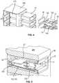
Figur 1 ; - Figur 4
- eine Explosionsdarstellung eines Bereichs eines Gerätegehäuses eines elektrochirurgischen Geräts mit den Buchseneinsatz gemäß
Figur 1 ; - Figur 5
- eine perspektivische Schnittansicht des Gerätegehäuses gemäß
Figur 4 mit eingesetztem Buchseneinsatz; - Figur 6
- eine weitere perspektivische Schnittansicht des Gerätegehäuses gemäß
Figur 4 ; - Figur 7
- eine Schnittansicht durch das Gerätegehäuse gemäß
Figur 4 und den darin eingesetzten Buchseneinsatz; - Figur 8
- eine horizontale Schnittansicht durch das Gerätegehäuse gemäß
Figur 4 und den Buchseneinsatz; - Figur 9
- eine perspektivische Ansicht eines Entnahmewerkzeugs für den erfindungsgemäßen Buchseneinsatz nach einem bevorzugten Ausführungsbeispiel;
Figur 10- eine Draufsicht auf das Entnahmewerkzeug gemäß
Figur 9 bei Verbindung mit dem Buchseneinsatz; und Figur 11- eine Detailansicht der Verbindung zwischen dem Entnahmewerkzeug und den
Buchseneinsatz gemäß Figur 10 .
- Figure 1
- a perspective rear view of a socket insert according to the invention according to a preferred embodiment;
- Figure 2
- a perspective front view of the socket insert according to FIG
Figure 1 ; - Figure 3
- an exploded view of the socket insert according to
Figure 1 ; - Figure 4
- an exploded view of a region of a device housing of an electrosurgical device with the socket insert according to FIG
Figure 1 ; - Figure 5
- a perspective sectional view of the device housing according to
Figure 4 with inserted socket insert; - Figure 6
- a further perspective sectional view of the device housing according to
Figure 4 ; - Figure 7
- a sectional view through the device housing according to
Figure 4 and the socket insert inserted therein; - Figure 8
- a horizontal sectional view through the device housing according to
Figure 4 and the socket insert; - Figure 9
- a perspective view of a removal tool for the socket insert according to the invention according to a preferred embodiment;
- Figure 10
- a plan view of the removal tool according to
Figure 9 when connected to the socket insert; and - Figure 11
- a detailed view of the connection between the removal tool and the socket insert according to FIG
Figure 10 .
Wie in
Das Rastmittel 15 weist einen keilförmigen Vorsprung 27 auf, der in einer Flucht zum Führungskanal 16 angeordnet ist. Beabstandet von dem keilförmigen Vorsprung 27 ist eine nach außen gerichtete Rastnase 30 vorgesehen. Die Rastnase 30 ist an einem freien Ende des Rastmittels 15 angeordnet. Es ist auch möglich, dass der keilförmige Vorsprung 27 direkt in die Rastnase 30 übergeht und zwischen beiden kein Abstand vorhanden ist (nicht dargestellt).The locking means 15 has a wedge-shaped
Durch den Führungskanal 16 erstreckt sich bei dem dargestellten Buchseneinsatz 100 eine Betätigungsstange 18. Die Betätigungsstange 18 weist eine Länge auf, die größer als die Länge des Führungskanals 16 ist. Insbesondere steht ein erstes Ende der Betätigungsstange 18 über die Austrittsöffnung 29 vor. Die Betätigungsstange 18 ist vorzugsweise fluchtend mit dem keilförmigen Vorsprung 27 des Rastmittels 15 ausgerichtet. An ihrem ersten Ende weist die Betätigungsstange 18 einen Anschlag 19 auf, der mit der Austrittsöffnung 29 zusammenwirkt, so dass eine Axialbewegung der Betätigungsstange 18 in Richtung zur Frontplatte 10 des Buchseneinsatzes 100 begrenzt ist. Der Anschlag 19 kann beispielsweise als ringförmige Rippe ausgebildet sein, die einen größeren Durchmesser als der Führungskanal 16 aufweist.In the illustrated
In
In
In der Explosionsdarstellung gemäß
Die Führungskanäle 16 sind ebenfalls einteilig mit dem Innengehäuse 110 bzw. dem Buchseneinsatz 100 ausgebildet. Die Führungskanäle 16 nehmen die Betätigungsstange 18 auf, die zum Entriegeln des Buchseneinsatzes 100 mit den Rastmitteln 15 zusammenwirken. Die Betätigungsstangen 18 bilden im Wesentlichen Stößel, die durch axiale Verschiebung auf das Rastmittel 15 einwirken, so dass die Rastnase 30 zum Entriegeln des Buchseneinsatz 100 nach innen ausgelegt wird. Das Rastmittel 15 bildet im Wesentlichen einen Schnapphaken, der durch Betätigung der Betätigungsstange 18 in die Entriegelungsstellung gebracht werden kann. Dabei wird die Betätigungsstange 18 gegen den keilförmigen Vorsprung 27 geschoben, so dass das rückwärtige, erste Ende der Betätigungsstange 18 entlang der schiefen Ebene des keilförmigen Vorsprungs 27 gleitet. Dies bewirkt eine nach innen gerichtete Auslenkung des Rastmittel 15.The
Der Buchseneinsatz 100 ist mit einen Einschubgehäuse 21 verbindbar, das wiederum fest in einem Gerätegehäuse 200 eines elektrochirurgischen Geräts angeordnet sein kann (
Das Einschubgehäuse 21 ist vorzugweise derart dimensioniert, dass die Frontplatte 10 im eingebauten Zustand des Buchseneinsatzes 100 mit einer Gehäusefront des elektrochirurgischen Geräts fluchtet. Der lichtdurchlässige Rahmen 20 kann über die Frontplatte 10 bzw. die Gehäusefront vorstehen. Dies ermöglicht einen dreidimensionalen Lichteffekt, der optisch ansprechend ist. Der über die Frontplatte 10 vorstehende Rahmen 20 ist gut in
Der lichtdurchlässige Rahmen 20 kann als Betriebszustandsanzeige genutzt werden, wobei Licht von einer Lichtquelle über das als Lichtleiter ausgebildete Einschubgehäuse 21 in den lichtdurchlässigen Rahmen 20 eingekoppelt wird. Die Lichtquelle wird vorzugsweise durch eine Hinterleuchtungsleiterplatte 32 gebildet, die hinter dem Buchseneinsatz 100 im Gerätegehäuse 200 angeordnet ist. In
Wie in den
Das Rastmittel 15 zur Verbindung des Buchseneinsatzes 100 mit dem Einschubgehäuse 21 ist in
Zum Entriegeln des Buchseneinsatzes 100 kommt ein Entnahmewerkzeug 23 zum Einsatz, dass in
Wie in den
Zum Einbau des Buchseneinsatzes 100 wird dieser einfach in das Einschubgehäuse 21 eingeschoben, das fest in der Buchsenaufnahme 210 des Gerätegehäuses 200 angeordnet, insbesondere stoffschlüssig oder mechanisch verankert, ist. Beispielsweise kann das Einschubgehäuse 21 mit der Buchsenaufnahme 210 stoff- oder formschlüssig verbunden sein. Durch Hineinschieben des Buchseneinsatzes 100 verrastet das Rastmittel 15 mit dem komplementären Mittel 22 in dem Einschubgehäuse 21, so dass der Buchseneinsatz 100 im Gerätegehäuse 200 fixiert ist.To install the
Da das Einschubgehäuse 21 gleichzeitig einen Lichtleiter bildet, ist der Rastmechanismus bzw. Schnapphakenmechanismus des Buchseneinsatzes 100 in den Aussparungen 28 der Seitenwände 12,13 angeordnet. So wird verhindert, dass der Rastmechanismus einem Lichtpfad im Lichtleiter behindert. Die elektrische Verbindung zwischen den Buchsen 110,120 und den elektrischen Komponenten im elektrochirurgischen Gerät wird über die Leiterplatte 130 hergestellt, die eine rückwärtige Steckverbindung 135 aufweist. Die elektrische Verbindung wird durch Einschieben des Buchseneinsatzes 100 in die Buchsenaufnahme 210 bereitgestellt, wobei die Steckerverbindung 135 mit einer entsprechenden Buchsenverbindung im Gerätegehäuse 200 in Eingriff gelangt.Since the slide-in
Zum Wechseln des Buchseneinsatzes 100 wird das Entnahmewerkzeug 23 genutzt, das auf die Betätigungsstangen 18 bzw. Stößel wirkt, die in den Führungskanälen 16 angeordnet sind. Über die Betätigungsstangen 18 kann mit dem Entnahmewerkzeug die Rastnase 30 des Rastmittels 15 nach innen ausgelenkt werden, so dass der Buchseneinsatz 100 freigegeben wird. Durch das Einschieben des Entnahmewerkzeugs 23 in die Führungskanäle 16 verbindet sich das Entnahmewerkzeug 23 formschlüssig mit den Buchseneinsatz 100. Dazu ist die Ausnehmung 26 in den Führungskanälen 16 vorgesehen, in die der vorstehende Rand 25 der Entriegelungsstange 24 eingreift. Die Ausnehmung 26 kann etwa 3 mm bis 4 mm von der Frontplatte 10 beabstandet in dem Führungskanal 16 angeordnet sein. Um den Formschluss zwischen dem Entnahmewerkzeug 23 und dem Buchseneinsatz 100 herzustellen, wird das Entnahmewerkzeug 23 gekippt. Dadurch gelangt der vorstehende Rand 25 in einen formschlüssigen Eingriff mit der Ausnehmung 26. Anschließend kann mit Hilfe des Entnahmewerkzeugs 23 der Buchseneinsatz 100 aus dem Einschubgehäuse 21 gezogen werden.To change the
Alternativ ist es möglich, anstelle der Betätigungsstange 18 ein Entnahmewerkzeug 23 einzusetzen, dessen Entriegelungsstangen 24 eine ausreichende Länge aufweisen, um direkt auf die Rastmittel 15 einzuwirken. Die Verwendung von Betätigungsstangen 18, die fest in die Führungskanäle 16 integriert sind, hat jedoch Vorteile, da der Buchseneinsatz 100 auf diese Weise vollständig abgeschlossen ist. Durch die Betätigungsstangen 18, die in der Arretierstellung bündig mit der Frontplatte 10 abschließen, vermittelt der Buchseneinsatz 100 einen optisch ansprechenden Gesamteindruck.Alternatively, instead of the actuating
Beim Vorschieben der Betätigungsstange 18 verrastet der Anschlag 19 der Betätigungsstange 18 außerdem mit dem keilförmigen Vorsprung 27, so dass die Betätigungsstange 18 in der Entriegelungsstellung arretiert wird. Der Anschlag 19 weist insofern eine Doppelfunktion auf. Einerseits verhindert der Anschlag 19, dass die Betätigungsstange 18 im Arretierzustand nach vorne, also über die Zugangsöffnung 17, aus dem Führungskanal 16 entnommen werden kann. Gleichzeitig verhindert der Anschlag 19 in der Entriegelungsstellung, dass die Betätigungsstange 18 in die Arretierstellung zurückfällt. So kann verhindert werden, dass ein bereits aus der Buchsenaufnahme 110 entnommener Buchseneinsatz 100 wieder in die Buchsenaufnahme 210 eingesetzt wird. Dies ist erst möglich, wenn die Betätigungsstange 18 manuell in ihre Ausgangslage, also die Arretierstellung zurückgebracht wurde.When the actuating
Mit der vorliegenden Erfindung kann ein Austausch des Buchseneinsatzes 100 erfolgen, ohne das Gerätegehäuse 200 des elektrochirurgischen Geräts öffnen zu müssen. Ein Zugriff auf stromführende Bauteile des elektrochirurgischen Geräts während des Austauschs des Buchseneinsatzes 100 wird so vermieden. Daher ist nach dem Austausch des Buchseneinsatzes 100 keine zusätzliche sicherheitstechnische Kontrolle erforderlich. Dies reduziert den Wartungsaufwand für elektrochirurgische Geräte. Außerdem ist der Austausch des Buchseneinsatzes 100 vereinfacht, da dazu keine aufwändigen Werkzeuge eingesetzt werden müssen. Insbesondere sind keine Schaubverbindungen oder dergleichen zu lösen, um den Buchseneinsatz 100 auszutauschen. Vielmehr erfolgt der Austausch des Buchseneinsatzes 100 einfach und schnell mithilfe des Entnahmewerkzeugs 23.With the present invention, the
- 100100
- BuchseneinsatzSocket insert
- 110110
- erste Buchsefirst socket
- 120120
- zweite Buchsesecond socket
- 130130
- LeiterplatteCircuit board
- 135135
- SteckverbindungConnector
- 140140
- InnengehäuseInner casing
- 150150
- FedermittelSpring means
- 200200
- GerätegehäuseDevice housing
- 210210
- BuchsenaufnahmeSocket receptacle
- 1010
- FrontplatteFront panel
- 1111
- SteckeröffnungConnector opening
- 1212th
- erste Seitenwandfirst side wall
- 1313th
- zweite Seitenwandsecond side wall
- 1414th
- AufnahmeraumRecording room
- 1515th
- RastmittelLocking means
- 1616
- FührungskanalGuide channel
- 1717th
- ZugangsöffnungAccess opening
- 1818th
- BetätigungsstangeOperating rod
- 1919th
- Anschlagattack
- 2020th
- lichtdurchlässiger Rahmentranslucent frame
- 2121
- EinschubgehäuseSlide-in housing
- 2222nd
- komplementäres Mittelcomplementary means
- 2323
- EntnahmewerkzeugRemoval tool
- 2424
- EntriegelungsstangeRelease bar
- 2525th
- vorstehender Randprotruding edge
- 2626th
- AusnehmungRecess
- 2727
- keilförmiger Vorsprungwedge-shaped projection
- 2828
- AussparungRecess
- 2929
- AustrittsöffnungOutlet opening
- 3030th
- RastnaseLocking lug
- 3131
- Bügelhanger
- 3232
- HinterleuchtungsleiterplatteBacklight circuit board
Claims (13)
- Electrosurgical device with a socket insert for an electrosurgical device, wherein the socket insert comprises:- a front plate (10), which has at least one plug opening (11),- first and second side walls (12, 13), which are connected to the front plate (10) and bound a receiving space (14) for electronic components, and- at least one latching means (15), which is connected to the first side wall (12) and can be transferred from a locking position into an unlocking position,wherein at least the first side wall (12) has a guide channel (16), which forms an access opening (17) in the front plate (10) and through which the latching means (15) can be actuated for unlocking,
wherein an axially displaceable actuating rod (18) is arranged in the guide channel (16), and wherein a first end of the actuating rod (18) is designed for unlocking the latching means (15) and can be moved out of the guide channel (16). - Electrosurgical device according to Claim 1,
characterized in that
the length of the actuating rod (18) is greater than the length of the guide channel (16). - Electrosurgical device according to Claim 1 or 2,
characterized in that
the actuating rod (18), in particular the first end of the actuating rod (18), has a stop (19), which interacts with the guide channel (16) for limiting the axial movement of the actuating rod (18). - Electrosurgical device according to one of Claims 1 to 3,
characterized in that
the latching means (15) has a wedge-shaped projection (27), which is in line with the actuating rod (18), wherein the height of the wedge-shaped projection (27) increases in the direction of advancement of the actuating rod (18). - Electrosurgical device according to one of Claims 1 to 4,
characterized in that
the latching means (15) has an outwardly directed latching lug, which for unlocking can be moved inwards in the direction of the receiving space (14). - Electrosurgical device according to one of Claims 1 to 5,
characterized in that
the first and second side walls (12, 13) respectively have a guide channel (16). - Electrosurgical device according to one of Claims 1 to 6,
characterized in that
the front plate (10) has a translucent frame (20), in particular a scattering frame, which is connected to a light guide. - Electrosurgical device according to Claim 7,characterized in that
the light guide forms a slide-in housing (21), which completely surrounds the receiving space (14) and can be connected to a light source. - Electrosurgical device according to Claim 8,
characterized in that
the slide-in housing (21) has at least one complementary means (22) for connecting to the latching means (15) of the side wall (12, 13), wherein the complementary means (22) is arranged on the inner wall of the slide-in housing (21) outside the light path. - Set with at least one socket insert (100) of an electrosurgical device according to one of the preceding claims and a removal tool (23), which has at least one unlocking rod (24) with a free end, in particular two unlocking rods (24) connected in a bow-like manner, with in each case a free end, which can be introduced into the guide channel (16).
- Set according to Claim 10,
characterized in that
the unlocking rod (24) has a protruding edge (25) at the free end, wherein the diameter of the edge (25) is smaller than the diameter of the guide channel (16). - Set according to Claim 11,
characterized in that
the guide channel (16) has a recess (26), which can be gripped from behind by the protruding edge (25) of the removal tool (23) for the removal of the socket insert from the device. - Method for removing a socket insert from an electrosurgical device according to one of Claims 1 to 9, in which- the removal tool (23) with the unlocking rod (24) is introduced into the guide channel (16) of the socket insert and the socket insert is unlocked,- the removal tool (23) is tilted and brought into interlocking connection with a recess (26) of the guide channel (16), and- the socket insert is removed from the device by the removal tool (23).
Priority Applications (8)
| Application Number | Priority Date | Filing Date | Title |
|---|---|---|---|
| PL14154490TPL2904982T3 (en) | 2014-02-10 | 2014-02-10 | Electrosurgical device having a female insert, set with a removing tool and method of removing a female insert |
| EP14154490.8AEP2904982B1 (en) | 2014-02-10 | 2014-02-10 | Electrosurgical device having a female insert, set with a removing tool and method of removing a female insert |
| CN201510061948.2ACN104836056B (en) | 2014-02-10 | 2015-02-05 | Electrosurgical device with socket, the external member with removing tool and socket removing method |
| BR102015002680-3ABR102015002680B1 (en) | 2014-02-10 | 2015-02-06 | Electrosurgical device with a socket insert for an electrosurgical device, socket insert, assembly with at least one socket insert and method for removing a socket insert |
| KR1020150018753AKR101716949B1 (en) | 2014-02-10 | 2015-02-06 | Socket insert for an electrosurgical device, electrosurgical device with a socket insert and set with a removal tool |
| JP2015021934AJP6095708B2 (en) | 2014-02-10 | 2015-02-06 | Socket insert for electrosurgical device, electrosurgical device having socket insert, and set having removal means |
| RU2015104125ARU2628623C2 (en) | 2014-02-10 | 2015-02-09 | Electrosurgical device with nest insert, set including nest insert and instrument for extraction and method of extracting nest insert |
| US14/616,873US9666974B2 (en) | 2014-02-10 | 2015-02-09 | Socket insert for an electrosurgical device, electrosurgical device with a socket insert and set with a removal tool |
Applications Claiming Priority (1)
| Application Number | Priority Date | Filing Date | Title |
|---|---|---|---|
| EP14154490.8AEP2904982B1 (en) | 2014-02-10 | 2014-02-10 | Electrosurgical device having a female insert, set with a removing tool and method of removing a female insert |
Publications (2)
| Publication Number | Publication Date |
|---|---|
| EP2904982A1 EP2904982A1 (en) | 2015-08-12 |
| EP2904982B1true EP2904982B1 (en) | 2021-04-07 |
Family
ID=50068932
Family Applications (1)
| Application Number | Title | Priority Date | Filing Date |
|---|---|---|---|
| EP14154490.8AActiveEP2904982B1 (en) | 2014-02-10 | 2014-02-10 | Electrosurgical device having a female insert, set with a removing tool and method of removing a female insert |
Country Status (8)
| Country | Link |
|---|---|
| US (1) | US9666974B2 (en) |
| EP (1) | EP2904982B1 (en) |
| JP (1) | JP6095708B2 (en) |
| KR (1) | KR101716949B1 (en) |
| CN (1) | CN104836056B (en) |
| BR (1) | BR102015002680B1 (en) |
| PL (1) | PL2904982T3 (en) |
| RU (1) | RU2628623C2 (en) |
Families Citing this family (30)
| Publication number | Priority date | Publication date | Assignee | Title |
|---|---|---|---|---|
| WO2015142787A1 (en)* | 2014-03-17 | 2015-09-24 | Intuitive Surgical Operations, Inc. | Multi-stage instrument connector |
| EP3462820B1 (en)* | 2017-09-29 | 2021-08-04 | Hosiden Corporation | Connector box and method of its assembly |
| JP6847015B2 (en)* | 2017-09-29 | 2021-03-24 | ホシデン株式会社 | Connector box |
| US12144136B2 (en) | 2018-09-07 | 2024-11-12 | Cilag Gmbh International | Modular surgical energy system with module positional awareness with digital logic |
| US20200078113A1 (en) | 2018-09-07 | 2020-03-12 | Ethicon Llc | Port presence detection system for modular energy system |
| US11923084B2 (en) | 2018-09-07 | 2024-03-05 | Cilag Gmbh International | First and second communication protocol arrangement for driving primary and secondary devices through a single port |
| US11510720B2 (en) | 2018-09-07 | 2022-11-29 | Cilag Gmbh International | Managing simultaneous monopolar outputs using duty cycle and synchronization |
| US11804679B2 (en) | 2018-09-07 | 2023-10-31 | Cilag Gmbh International | Flexible hand-switch circuit |
| US11218822B2 (en) | 2019-03-29 | 2022-01-04 | Cilag Gmbh International | Audio tone construction for an energy module of a modular energy system |
| EP3952780A4 (en) | 2019-04-10 | 2022-08-17 | U.S. Patent Innovations LLC | Configurable electrosurgical generator housing |
| US11362472B2 (en)* | 2019-05-21 | 2022-06-14 | Te Connectivity Corporation | Terminal extraction tool |
| CN112003077A (en)* | 2019-05-25 | 2020-11-27 | 费斯托股份两合公司 | Coupling system for electrical connections |
| EP3758157B1 (en) | 2019-06-27 | 2024-12-25 | Erbe Elektromedizin GmbH | Device with a service interface and method for maintaining the device |
| USD939545S1 (en) | 2019-09-05 | 2021-12-28 | Cilag Gmbh International | Display panel or portion thereof with graphical user interface for energy module |
| AT523134B1 (en) | 2019-11-11 | 2022-02-15 | Neutrik Ag | built-in connector |
| US11950860B2 (en) | 2021-03-30 | 2024-04-09 | Cilag Gmbh International | User interface mitigation techniques for modular energy systems |
| US12235697B2 (en) | 2021-03-30 | 2025-02-25 | Cilag Gmbh International | Backplane connector attachment mechanism for modular energy system |
| US12004824B2 (en) | 2021-03-30 | 2024-06-11 | Cilag Gmbh International | Architecture for modular energy system |
| US12369994B2 (en) | 2021-03-30 | 2025-07-29 | Cilag Gmbh International | Modular energy system with multi-energy port splitter for multiple energy devices |
| US12040749B2 (en) | 2021-03-30 | 2024-07-16 | Cilag Gmbh International | Modular energy system with dual amplifiers and techniques for updating parameters thereof |
| US11963727B2 (en) | 2021-03-30 | 2024-04-23 | Cilag Gmbh International | Method for system architecture for modular energy system |
| US12228987B2 (en) | 2021-03-30 | 2025-02-18 | Cilag Gmbh International | Method for energy delivery for modular energy system |
| US11857252B2 (en)* | 2021-03-30 | 2024-01-02 | Cilag Gmbh International | Bezel with light blocking features for modular energy system |
| US11978554B2 (en) | 2021-03-30 | 2024-05-07 | Cilag Gmbh International | Radio frequency identification token for wireless surgical instruments |
| US11980411B2 (en) | 2021-03-30 | 2024-05-14 | Cilag Gmbh International | Header for modular energy system |
| US11968776B2 (en) | 2021-03-30 | 2024-04-23 | Cilag Gmbh International | Method for mechanical packaging for modular energy system |
| US20220331051A1 (en) | 2021-04-14 | 2022-10-20 | Cilag Gmbh International | Utilizing contextual parameters of one or more surgical devices to predict a frequency interval for displaying surgical information |
| US12079460B2 (en) | 2022-06-28 | 2024-09-03 | Cilag Gmbh International | Profiles for modular energy system |
| EP4344663A1 (en)* | 2022-09-29 | 2024-04-03 | Olympus Winter & Ibe GmbH | Electrosurgical generator with modular output socket for electrosurgical instrument |
| EP4389041A1 (en)* | 2022-12-23 | 2024-06-26 | Olympus Winter & Ibe GmbH | Electrosurgical generator having a modular output socket |
Family Cites Families (21)
| Publication number | Priority date | Publication date | Assignee | Title |
|---|---|---|---|---|
| GB2243729A (en) | 1990-04-17 | 1991-11-06 | Amp Inc | Electrical module retention/ejection system |
| CA2298096C (en)* | 1999-02-05 | 2009-06-30 | Fiber Connections Inc. | Connector for fibre optic cable |
| US6200160B1 (en)* | 1999-04-26 | 2001-03-13 | Avaya Technologies Corp. | Protective console unit for electrical or optical connectors |
| US6361242B1 (en)* | 2000-02-29 | 2002-03-26 | Avaya Technology Corp. | Connector security latching mechanism |
| US6361357B1 (en) | 2000-04-13 | 2002-03-26 | 3Com Corporation | Remotely illuminated electronic connector for improving viewing of status indicators |
| JP2002119517A (en)* | 2000-10-18 | 2002-04-23 | Olympus Optical Co Ltd | Endoscopic surgery device |
| DE10228791A1 (en)* | 2002-06-27 | 2004-01-29 | Erbe Elektromedizin Gmbh | Connection device for an electrosurgical instrument |
| US20040097912A1 (en)* | 2002-11-18 | 2004-05-20 | Gonnering Wayne J. | Electrosurgical generator and method with removable front panel having replaceable electrical connection sockets and illuminated receptacles |
| US6835082B2 (en) | 2002-11-18 | 2004-12-28 | Conmed Corporation | Monopolar electrosurgical multi-plug connector device and method which accepts multiple different connector plugs |
| CN1771633B (en) | 2003-01-27 | 2012-05-23 | 多米那英国有限公司 | Improvements to safety covers for electrical sockets etc. |
| JP4429272B2 (en) | 2003-11-20 | 2010-03-10 | コヴィディエン アクチェンゲゼルシャフト | Connector system for electrosurgical generator |
| RU2241407C1 (en)* | 2003-12-16 | 2004-12-10 | Зао "Вниимп-Вита" | Device for applying electric surgery |
| US7540871B2 (en)* | 2005-08-03 | 2009-06-02 | Conmed Corporation | Integrated three-port receptacle and method for connecting hand and foot switched electrosurgical accessories |
| US9222284B2 (en)* | 2007-05-30 | 2015-12-29 | Security People, Inc. | Electronic locks particularly for office furniture |
| MX2010001515A (en)* | 2007-08-09 | 2010-03-10 | Belden Cdt Canada Inc | TELESCOPIC CONNECTOR ASSEMBLY. |
| US7758369B2 (en)* | 2008-04-25 | 2010-07-20 | Tyco Electronics Corporation | Plug connector for use with a receptacle |
| DE102009027660B4 (en) | 2009-07-13 | 2015-02-05 | Tyco Electronics Amp Gmbh | Connector with a blocking element and housing with a blocking element. |
| US9050093B2 (en)* | 2009-10-09 | 2015-06-09 | Ethicon Endo-Surgery, Inc. | Surgical generator for ultrasonic and electrosurgical devices |
| DE202011050061U1 (en)* | 2011-05-06 | 2011-07-26 | Aesculap Ag | Surgical coupling system and surgical drive system |
| US8591240B2 (en)* | 2012-04-04 | 2013-11-26 | Apple Inc. | Systems and methods for ejecting removable modules from electronic devices |
| EP2656805B1 (en)* | 2012-04-26 | 2017-03-15 | Erbe Elektromedizin GmbH | Socket assembly for an electric medical device |
- 2014
- 2014-02-10EPEP14154490.8Apatent/EP2904982B1/enactiveActive
- 2014-02-10PLPL14154490Tpatent/PL2904982T3/enunknown
- 2015
- 2015-02-05CNCN201510061948.2Apatent/CN104836056B/enactiveActive
- 2015-02-06JPJP2015021934Apatent/JP6095708B2/enactiveActive
- 2015-02-06KRKR1020150018753Apatent/KR101716949B1/enactiveActive
- 2015-02-06BRBR102015002680-3Apatent/BR102015002680B1/enactiveIP Right Grant
- 2015-02-09USUS14/616,873patent/US9666974B2/enactiveActive
- 2015-02-09RURU2015104125Apatent/RU2628623C2/enactive
Non-Patent Citations (1)
| Title |
|---|
| None* |
Also Published As
| Publication number | Publication date |
|---|---|
| RU2628623C2 (en) | 2017-08-21 |
| PL2904982T3 (en) | 2021-07-19 |
| KR101716949B1 (en) | 2017-03-15 |
| RU2015104125A (en) | 2016-08-27 |
| CN104836056B (en) | 2017-11-28 |
| EP2904982A1 (en) | 2015-08-12 |
| US9666974B2 (en) | 2017-05-30 |
| CN104836056A (en) | 2015-08-12 |
| JP2015150428A (en) | 2015-08-24 |
| JP6095708B2 (en) | 2017-03-15 |
| BR102015002680A2 (en) | 2018-02-27 |
| BR102015002680B1 (en) | 2022-03-03 |
| US20150229083A1 (en) | 2015-08-13 |
| KR20150094530A (en) | 2015-08-19 |
Similar Documents
| Publication | Publication Date | Title |
|---|---|---|
| EP2904982B1 (en) | Electrosurgical device having a female insert, set with a removing tool and method of removing a female insert | |
| EP1151338B1 (en) | Optical connector | |
| DE102014106277B4 (en) | An electronics housing with a terminal block for an electronic device | |
| DE102009059685A1 (en) | Plug element with a locking mechanism | |
| DE60221944T2 (en) | Connector with coupling device | |
| DE202006012163U1 (en) | Electrical device e.g. emitter, housing, has two housing modules that are connected detachably with one another at wall regions that lie opposite to each other by corresponding pairs of slits | |
| EP2339701A2 (en) | Circuit board connector with locking device | |
| EP4191803A1 (en) | Unlocking member and electrical connector provided with same | |
| DE102015222561A1 (en) | Holding frame for holding connector modules | |
| EP1912285A1 (en) | Electric or electronic device | |
| EP3472414B1 (en) | Handle assembly for a vehicle | |
| DE2414825B2 (en) | BUILT-IN SIGNAL UNIT | |
| DE102014107029B4 (en) | connector system | |
| DE102011002135A1 (en) | Plug element with second contact fuse | |
| DE102012223739B4 (en) | Connector and connector system | |
| DE112011104984T5 (en) | twist lock | |
| EP2762899B1 (en) | Electricity meter with interlocking housing parts | |
| DE102016208673A1 (en) | Connector with latch for secondary locking of contact partners | |
| EP3044040B1 (en) | Component carrier | |
| DE3310474A1 (en) | Assembly for pushing into mounting racks having a lock, and devices for removing the assembly and releasing the lock | |
| EP1786252A1 (en) | Device and method for inserting or removing a pluggable unit | |
| EP0988668B1 (en) | Zero insertion force connector for circuit boards | |
| DE102016206162B4 (en) | Housing with two opposite side wall elements, a front side element and a rear side element | |
| DE102010013311A1 (en) | Sensor fastening device and associated sensor arrangement | |
| DE20019792U1 (en) | Connector housing with coding device |
Legal Events
| Date | Code | Title | Description |
|---|---|---|---|
| PUAI | Public reference made under article 153(3) epc to a published international application that has entered the european phase | Free format text:ORIGINAL CODE: 0009012 | |
| 17P | Request for examination filed | Effective date:20140210 | |
| AK | Designated contracting states | Kind code of ref document:A1 Designated state(s):AL AT BE BG CH CY CZ DE DK EE ES FI FR GB GR HR HU IE IS IT LI LT LU LV MC MK MT NL NO PL PT RO RS SE SI SK SM TR | |
| AX | Request for extension of the european patent | Extension state:BA ME | |
| 17Q | First examination report despatched | Effective date:20160301 | |
| RAP1 | Party data changed (applicant data changed or rights of an application transferred) | Owner name:ERBE ELEKTROMEDIZIN GMBH | |
| STAA | Information on the status of an ep patent application or granted ep patent | Free format text:STATUS: EXAMINATION IS IN PROGRESS | |
| GRAP | Despatch of communication of intention to grant a patent | Free format text:ORIGINAL CODE: EPIDOSNIGR1 | |
| STAA | Information on the status of an ep patent application or granted ep patent | Free format text:STATUS: GRANT OF PATENT IS INTENDED | |
| RIC1 | Information provided on ipc code assigned before grant | Ipc:A61B 18/12 20060101AFI20200921BHEP Ipc:H01R 13/518 20060101ALI20200921BHEP | |
| INTG | Intention to grant announced | Effective date:20201012 | |
| GRAS | Grant fee paid | Free format text:ORIGINAL CODE: EPIDOSNIGR3 | |
| GRAA | (expected) grant | Free format text:ORIGINAL CODE: 0009210 | |
| STAA | Information on the status of an ep patent application or granted ep patent | Free format text:STATUS: THE PATENT HAS BEEN GRANTED | |
| AK | Designated contracting states | Kind code of ref document:B1 Designated state(s):AL AT BE BG CH CY CZ DE DK EE ES FI FR GB GR HR HU IE IS IT LI LT LU LV MC MK MT NL NO PL PT RO RS SE SI SK SM TR | |
| REG | Reference to a national code | Ref country code:GB Ref legal event code:FG4D Free format text:NOT ENGLISH | |
| REG | Reference to a national code | Ref country code:AT Ref legal event code:REF Ref document number:1378668 Country of ref document:AT Kind code of ref document:T Effective date:20210415 Ref country code:CH Ref legal event code:EP | |
| REG | Reference to a national code | Ref country code:DE Ref legal event code:R096 Ref document number:502014015451 Country of ref document:DE | |
| REG | Reference to a national code | Ref country code:IE Ref legal event code:FG4D Free format text:LANGUAGE OF EP DOCUMENT: GERMAN | |
| REG | Reference to a national code | Ref country code:LT Ref legal event code:MG9D | |
| REG | Reference to a national code | Ref country code:NL Ref legal event code:MP Effective date:20210407 | |
| PG25 | Lapsed in a contracting state [announced via postgrant information from national office to epo] | Ref country code:HR Free format text:LAPSE BECAUSE OF FAILURE TO SUBMIT A TRANSLATION OF THE DESCRIPTION OR TO PAY THE FEE WITHIN THE PRESCRIBED TIME-LIMIT Effective date:20210407 Ref country code:FI Free format text:LAPSE BECAUSE OF FAILURE TO SUBMIT A TRANSLATION OF THE DESCRIPTION OR TO PAY THE FEE WITHIN THE PRESCRIBED TIME-LIMIT Effective date:20210407 Ref country code:NL Free format text:LAPSE BECAUSE OF FAILURE TO SUBMIT A TRANSLATION OF THE DESCRIPTION OR TO PAY THE FEE WITHIN THE PRESCRIBED TIME-LIMIT Effective date:20210407 Ref country code:LT Free format text:LAPSE BECAUSE OF FAILURE TO SUBMIT A TRANSLATION OF THE DESCRIPTION OR TO PAY THE FEE WITHIN THE PRESCRIBED TIME-LIMIT Effective date:20210407 Ref country code:BG Free format text:LAPSE BECAUSE OF FAILURE TO SUBMIT A TRANSLATION OF THE DESCRIPTION OR TO PAY THE FEE WITHIN THE PRESCRIBED TIME-LIMIT Effective date:20210707 | |
| PG25 | Lapsed in a contracting state [announced via postgrant information from national office to epo] | Ref country code:LV Free format text:LAPSE BECAUSE OF FAILURE TO SUBMIT A TRANSLATION OF THE DESCRIPTION OR TO PAY THE FEE WITHIN THE PRESCRIBED TIME-LIMIT Effective date:20210407 Ref country code:GR Free format text:LAPSE BECAUSE OF FAILURE TO SUBMIT A TRANSLATION OF THE DESCRIPTION OR TO PAY THE FEE WITHIN THE PRESCRIBED TIME-LIMIT Effective date:20210708 Ref country code:IS Free format text:LAPSE BECAUSE OF FAILURE TO SUBMIT A TRANSLATION OF THE DESCRIPTION OR TO PAY THE FEE WITHIN THE PRESCRIBED TIME-LIMIT Effective date:20210807 Ref country code:RS Free format text:LAPSE BECAUSE OF FAILURE TO SUBMIT A TRANSLATION OF THE DESCRIPTION OR TO PAY THE FEE WITHIN THE PRESCRIBED TIME-LIMIT Effective date:20210407 Ref country code:SE Free format text:LAPSE BECAUSE OF FAILURE TO SUBMIT A TRANSLATION OF THE DESCRIPTION OR TO PAY THE FEE WITHIN THE PRESCRIBED TIME-LIMIT Effective date:20210407 Ref country code:PT Free format text:LAPSE BECAUSE OF FAILURE TO SUBMIT A TRANSLATION OF THE DESCRIPTION OR TO PAY THE FEE WITHIN THE PRESCRIBED TIME-LIMIT Effective date:20210809 Ref country code:NO Free format text:LAPSE BECAUSE OF FAILURE TO SUBMIT A TRANSLATION OF THE DESCRIPTION OR TO PAY THE FEE WITHIN THE PRESCRIBED TIME-LIMIT Effective date:20210707 Ref country code:ES Free format text:LAPSE BECAUSE OF FAILURE TO SUBMIT A TRANSLATION OF THE DESCRIPTION OR TO PAY THE FEE WITHIN THE PRESCRIBED TIME-LIMIT Effective date:20210407 | |
| REG | Reference to a national code | Ref country code:DE Ref legal event code:R097 Ref document number:502014015451 Country of ref document:DE | |
| PG25 | Lapsed in a contracting state [announced via postgrant information from national office to epo] | Ref country code:RO Free format text:LAPSE BECAUSE OF FAILURE TO SUBMIT A TRANSLATION OF THE DESCRIPTION OR TO PAY THE FEE WITHIN THE PRESCRIBED TIME-LIMIT Effective date:20210407 Ref country code:SK Free format text:LAPSE BECAUSE OF FAILURE TO SUBMIT A TRANSLATION OF THE DESCRIPTION OR TO PAY THE FEE WITHIN THE PRESCRIBED TIME-LIMIT Effective date:20210407 Ref country code:SM Free format text:LAPSE BECAUSE OF FAILURE TO SUBMIT A TRANSLATION OF THE DESCRIPTION OR TO PAY THE FEE WITHIN THE PRESCRIBED TIME-LIMIT Effective date:20210407 Ref country code:CZ Free format text:LAPSE BECAUSE OF FAILURE TO SUBMIT A TRANSLATION OF THE DESCRIPTION OR TO PAY THE FEE WITHIN THE PRESCRIBED TIME-LIMIT Effective date:20210407 Ref country code:DK Free format text:LAPSE BECAUSE OF FAILURE TO SUBMIT A TRANSLATION OF THE DESCRIPTION OR TO PAY THE FEE WITHIN THE PRESCRIBED TIME-LIMIT Effective date:20210407 Ref country code:EE Free format text:LAPSE BECAUSE OF FAILURE TO SUBMIT A TRANSLATION OF THE DESCRIPTION OR TO PAY THE FEE WITHIN THE PRESCRIBED TIME-LIMIT Effective date:20210407 | |
| PLBE | No opposition filed within time limit | Free format text:ORIGINAL CODE: 0009261 | |
| STAA | Information on the status of an ep patent application or granted ep patent | Free format text:STATUS: NO OPPOSITION FILED WITHIN TIME LIMIT | |
| 26N | No opposition filed | Effective date:20220110 | |
| PG25 | Lapsed in a contracting state [announced via postgrant information from national office to epo] | Ref country code:IS Free format text:LAPSE BECAUSE OF FAILURE TO SUBMIT A TRANSLATION OF THE DESCRIPTION OR TO PAY THE FEE WITHIN THE PRESCRIBED TIME-LIMIT Effective date:20210807 Ref country code:AL Free format text:LAPSE BECAUSE OF FAILURE TO SUBMIT A TRANSLATION OF THE DESCRIPTION OR TO PAY THE FEE WITHIN THE PRESCRIBED TIME-LIMIT Effective date:20210407 | |
| PG25 | Lapsed in a contracting state [announced via postgrant information from national office to epo] | Ref country code:MC Free format text:LAPSE BECAUSE OF FAILURE TO SUBMIT A TRANSLATION OF THE DESCRIPTION OR TO PAY THE FEE WITHIN THE PRESCRIBED TIME-LIMIT Effective date:20210407 | |
| REG | Reference to a national code | Ref country code:CH Ref legal event code:PL | |
| REG | Reference to a national code | Ref country code:BE Ref legal event code:MM Effective date:20220228 | |
| PG25 | Lapsed in a contracting state [announced via postgrant information from national office to epo] | Ref country code:LU Free format text:LAPSE BECAUSE OF NON-PAYMENT OF DUE FEES Effective date:20220210 | |
| PG25 | Lapsed in a contracting state [announced via postgrant information from national office to epo] | Ref country code:LI Free format text:LAPSE BECAUSE OF NON-PAYMENT OF DUE FEES Effective date:20220228 Ref country code:IE Free format text:LAPSE BECAUSE OF NON-PAYMENT OF DUE FEES Effective date:20220210 Ref country code:CH Free format text:LAPSE BECAUSE OF NON-PAYMENT OF DUE FEES Effective date:20220228 | |
| PG25 | Lapsed in a contracting state [announced via postgrant information from national office to epo] | Ref country code:BE Free format text:LAPSE BECAUSE OF NON-PAYMENT OF DUE FEES Effective date:20220228 | |
| REG | Reference to a national code | Ref country code:AT Ref legal event code:MM01 Ref document number:1378668 Country of ref document:AT Kind code of ref document:T Effective date:20220210 | |
| PG25 | Lapsed in a contracting state [announced via postgrant information from national office to epo] | Ref country code:AT Free format text:LAPSE BECAUSE OF NON-PAYMENT OF DUE FEES Effective date:20220210 | |
| PG25 | Lapsed in a contracting state [announced via postgrant information from national office to epo] | Ref country code:HU Free format text:LAPSE BECAUSE OF FAILURE TO SUBMIT A TRANSLATION OF THE DESCRIPTION OR TO PAY THE FEE WITHIN THE PRESCRIBED TIME-LIMIT; INVALID AB INITIO Effective date:20140210 | |
| PG25 | Lapsed in a contracting state [announced via postgrant information from national office to epo] | Ref country code:MK Free format text:LAPSE BECAUSE OF FAILURE TO SUBMIT A TRANSLATION OF THE DESCRIPTION OR TO PAY THE FEE WITHIN THE PRESCRIBED TIME-LIMIT Effective date:20210407 Ref country code:CY Free format text:LAPSE BECAUSE OF FAILURE TO SUBMIT A TRANSLATION OF THE DESCRIPTION OR TO PAY THE FEE WITHIN THE PRESCRIBED TIME-LIMIT Effective date:20210407 | |
| PG25 | Lapsed in a contracting state [announced via postgrant information from national office to epo] | Ref country code:TR Free format text:LAPSE BECAUSE OF FAILURE TO SUBMIT A TRANSLATION OF THE DESCRIPTION OR TO PAY THE FEE WITHIN THE PRESCRIBED TIME-LIMIT Effective date:20210407 | |
| PG25 | Lapsed in a contracting state [announced via postgrant information from national office to epo] | Ref country code:MT Free format text:LAPSE BECAUSE OF FAILURE TO SUBMIT A TRANSLATION OF THE DESCRIPTION OR TO PAY THE FEE WITHIN THE PRESCRIBED TIME-LIMIT Effective date:20210407 | |
| PGFP | Annual fee paid to national office [announced via postgrant information from national office to epo] | Ref country code:DE Payment date:20250226 Year of fee payment:12 | |
| PGFP | Annual fee paid to national office [announced via postgrant information from national office to epo] | Ref country code:FR Payment date:20250224 Year of fee payment:12 Ref country code:PL Payment date:20250115 Year of fee payment:12 | |
| PGFP | Annual fee paid to national office [announced via postgrant information from national office to epo] | Ref country code:GB Payment date:20250218 Year of fee payment:12 Ref country code:IT Payment date:20250225 Year of fee payment:12 |