EP2903569B1 - Helical balloon catheter - Google Patents
Helical balloon catheterDownload PDFInfo
- Publication number
- EP2903569B1 EP2903569B1EP13844076.3AEP13844076AEP2903569B1EP 2903569 B1EP2903569 B1EP 2903569B1EP 13844076 AEP13844076 AEP 13844076AEP 2903569 B1EP2903569 B1EP 2903569B1
- Authority
- EP
- European Patent Office
- Prior art keywords
- catheter
- section
- helical profile
- deflectable
- lumen
- Prior art date
- Legal status (The legal status is an assumption and is not a legal conclusion. Google has not performed a legal analysis and makes no representation as to the accuracy of the status listed.)
- Active
Links
- 239000000463materialSubstances0.000claimsdescription45
- 239000013013elastic materialSubstances0.000claimsdescription29
- 239000012530fluidSubstances0.000description26
- 238000000034methodMethods0.000description14
- KPUWHANPEXNPJT-UHFFFAOYSA-NdisiloxaneChemical class[SiH3]O[SiH3]KPUWHANPEXNPJT-UHFFFAOYSA-N0.000description9
- 210000000056organAnatomy0.000description6
- 239000004677NylonSubstances0.000description3
- 239000007943implantSubstances0.000description3
- 229920001778nylonPolymers0.000description3
- 229920002635polyurethanePolymers0.000description3
- 229920002614Polyether block amidePolymers0.000description2
- 210000003484anatomyAnatomy0.000description2
- 230000015572biosynthetic processEffects0.000description2
- 210000004351coronary vesselAnatomy0.000description2
- 239000003814drugSubstances0.000description2
- 238000001125extrusionMethods0.000description2
- 239000000203mixtureSubstances0.000description2
- 239000004814polyurethaneSubstances0.000description2
- 230000005855radiationEffects0.000description2
- 210000002376aorta thoracicAnatomy0.000description1
- 210000001367arteryAnatomy0.000description1
- 230000017531blood circulationEffects0.000description1
- 238000002725brachytherapyMethods0.000description1
- 239000003795chemical substances by applicationSubstances0.000description1
- 230000007423decreaseEffects0.000description1
- 229940079593drugDrugs0.000description1
- 239000000126substanceSubstances0.000description1
- 230000009466transformationEffects0.000description1
- 210000005166vasculatureAnatomy0.000description1
Images


Classifications
- A—HUMAN NECESSITIES
- A61—MEDICAL OR VETERINARY SCIENCE; HYGIENE
- A61M—DEVICES FOR INTRODUCING MEDIA INTO, OR ONTO, THE BODY; DEVICES FOR TRANSDUCING BODY MEDIA OR FOR TAKING MEDIA FROM THE BODY; DEVICES FOR PRODUCING OR ENDING SLEEP OR STUPOR
- A61M25/00—Catheters; Hollow probes
- A61M25/01—Introducing, guiding, advancing, emplacing or holding catheters
- A61M25/0105—Steering means as part of the catheter or advancing means; Markers for positioning
- A61M25/0133—Tip steering devices
- A61M25/0155—Tip steering devices with hydraulic or pneumatic means, e.g. balloons or inflatable compartments
- A—HUMAN NECESSITIES
- A61—MEDICAL OR VETERINARY SCIENCE; HYGIENE
- A61F—FILTERS IMPLANTABLE INTO BLOOD VESSELS; PROSTHESES; DEVICES PROVIDING PATENCY TO, OR PREVENTING COLLAPSING OF, TUBULAR STRUCTURES OF THE BODY, e.g. STENTS; ORTHOPAEDIC, NURSING OR CONTRACEPTIVE DEVICES; FOMENTATION; TREATMENT OR PROTECTION OF EYES OR EARS; BANDAGES, DRESSINGS OR ABSORBENT PADS; FIRST-AID KITS
- A61F2/00—Filters implantable into blood vessels; Prostheses, i.e. artificial substitutes or replacements for parts of the body; Appliances for connecting them with the body; Devices providing patency to, or preventing collapsing of, tubular structures of the body, e.g. stents
- A61F2/95—Instruments specially adapted for placement or removal of stents or stent-grafts
- A61F2/958—Inflatable balloons for placing stents or stent-grafts
- A—HUMAN NECESSITIES
- A61—MEDICAL OR VETERINARY SCIENCE; HYGIENE
- A61M—DEVICES FOR INTRODUCING MEDIA INTO, OR ONTO, THE BODY; DEVICES FOR TRANSDUCING BODY MEDIA OR FOR TAKING MEDIA FROM THE BODY; DEVICES FOR PRODUCING OR ENDING SLEEP OR STUPOR
- A61M25/00—Catheters; Hollow probes
- A61M25/0067—Catheters; Hollow probes characterised by the distal end, e.g. tips
- A61M25/0074—Dynamic characteristics of the catheter tip, e.g. openable, closable, expandable or deformable
- A—HUMAN NECESSITIES
- A61—MEDICAL OR VETERINARY SCIENCE; HYGIENE
- A61M—DEVICES FOR INTRODUCING MEDIA INTO, OR ONTO, THE BODY; DEVICES FOR TRANSDUCING BODY MEDIA OR FOR TAKING MEDIA FROM THE BODY; DEVICES FOR PRODUCING OR ENDING SLEEP OR STUPOR
- A61M25/00—Catheters; Hollow probes
- A61M25/01—Introducing, guiding, advancing, emplacing or holding catheters
- A61M25/0105—Steering means as part of the catheter or advancing means; Markers for positioning
- A61M25/0133—Tip steering devices
- A61M25/0147—Tip steering devices with movable mechanical means, e.g. pull wires
- A—HUMAN NECESSITIES
- A61—MEDICAL OR VETERINARY SCIENCE; HYGIENE
- A61M—DEVICES FOR INTRODUCING MEDIA INTO, OR ONTO, THE BODY; DEVICES FOR TRANSDUCING BODY MEDIA OR FOR TAKING MEDIA FROM THE BODY; DEVICES FOR PRODUCING OR ENDING SLEEP OR STUPOR
- A61M25/00—Catheters; Hollow probes
- A61M25/10—Balloon catheters
- A61M25/1002—Balloon catheters characterised by balloon shape
- A—HUMAN NECESSITIES
- A61—MEDICAL OR VETERINARY SCIENCE; HYGIENE
- A61F—FILTERS IMPLANTABLE INTO BLOOD VESSELS; PROSTHESES; DEVICES PROVIDING PATENCY TO, OR PREVENTING COLLAPSING OF, TUBULAR STRUCTURES OF THE BODY, e.g. STENTS; ORTHOPAEDIC, NURSING OR CONTRACEPTIVE DEVICES; FOMENTATION; TREATMENT OR PROTECTION OF EYES OR EARS; BANDAGES, DRESSINGS OR ABSORBENT PADS; FIRST-AID KITS
- A61F2230/00—Geometry of prostheses classified in groups A61F2/00 - A61F2/26 or A61F2/82 or A61F9/00 or A61F11/00 or subgroups thereof
- A61F2230/0063—Three-dimensional shapes
- A61F2230/0091—Three-dimensional shapes helically-coiled or spirally-coiled, i.e. having a 2-D spiral cross-section
- A—HUMAN NECESSITIES
- A61—MEDICAL OR VETERINARY SCIENCE; HYGIENE
- A61M—DEVICES FOR INTRODUCING MEDIA INTO, OR ONTO, THE BODY; DEVICES FOR TRANSDUCING BODY MEDIA OR FOR TAKING MEDIA FROM THE BODY; DEVICES FOR PRODUCING OR ENDING SLEEP OR STUPOR
- A61M25/00—Catheters; Hollow probes
- A61M25/0021—Catheters; Hollow probes characterised by the form of the tubing
- A61M25/0023—Catheters; Hollow probes characterised by the form of the tubing by the form of the lumen, e.g. cross-section, variable diameter
- A61M2025/0024—Expandable catheters or sheaths
- A—HUMAN NECESSITIES
- A61—MEDICAL OR VETERINARY SCIENCE; HYGIENE
- A61M—DEVICES FOR INTRODUCING MEDIA INTO, OR ONTO, THE BODY; DEVICES FOR TRANSDUCING BODY MEDIA OR FOR TAKING MEDIA FROM THE BODY; DEVICES FOR PRODUCING OR ENDING SLEEP OR STUPOR
- A61M25/00—Catheters; Hollow probes
- A61M25/01—Introducing, guiding, advancing, emplacing or holding catheters
- A61M25/0105—Steering means as part of the catheter or advancing means; Markers for positioning
- A61M25/0133—Tip steering devices
- A61M2025/0163—Looped catheters
- A—HUMAN NECESSITIES
- A61—MEDICAL OR VETERINARY SCIENCE; HYGIENE
- A61M—DEVICES FOR INTRODUCING MEDIA INTO, OR ONTO, THE BODY; DEVICES FOR TRANSDUCING BODY MEDIA OR FOR TAKING MEDIA FROM THE BODY; DEVICES FOR PRODUCING OR ENDING SLEEP OR STUPOR
- A61M25/00—Catheters; Hollow probes
- A61M25/10—Balloon catheters
- A61M2025/1043—Balloon catheters with special features or adapted for special applications
- A61M2025/105—Balloon catheters with special features or adapted for special applications having a balloon suitable for drug delivery, e.g. by using holes for delivery, drug coating or membranes
- A—HUMAN NECESSITIES
- A61—MEDICAL OR VETERINARY SCIENCE; HYGIENE
- A61M—DEVICES FOR INTRODUCING MEDIA INTO, OR ONTO, THE BODY; DEVICES FOR TRANSDUCING BODY MEDIA OR FOR TAKING MEDIA FROM THE BODY; DEVICES FOR PRODUCING OR ENDING SLEEP OR STUPOR
- A61M25/00—Catheters; Hollow probes
- A61M25/10—Balloon catheters
- A61M2025/1043—Balloon catheters with special features or adapted for special applications
- A61M2025/1059—Balloon catheters with special features or adapted for special applications having different inflatable sections mainly depending on the response to the inflation pressure, e.g. due to different material properties
- A—HUMAN NECESSITIES
- A61—MEDICAL OR VETERINARY SCIENCE; HYGIENE
- A61M—DEVICES FOR INTRODUCING MEDIA INTO, OR ONTO, THE BODY; DEVICES FOR TRANSDUCING BODY MEDIA OR FOR TAKING MEDIA FROM THE BODY; DEVICES FOR PRODUCING OR ENDING SLEEP OR STUPOR
- A61M25/00—Catheters; Hollow probes
- A61M25/10—Balloon catheters
- A61M2025/1043—Balloon catheters with special features or adapted for special applications
- A61M2025/1097—Balloon catheters with special features or adapted for special applications with perfusion means for enabling blood circulation only while the balloon is in an inflated state, e.g. temporary by-pass within balloon
- A—HUMAN NECESSITIES
- A61—MEDICAL OR VETERINARY SCIENCE; HYGIENE
- A61M—DEVICES FOR INTRODUCING MEDIA INTO, OR ONTO, THE BODY; DEVICES FOR TRANSDUCING BODY MEDIA OR FOR TAKING MEDIA FROM THE BODY; DEVICES FOR PRODUCING OR ENDING SLEEP OR STUPOR
- A61M2210/00—Anatomical parts of the body
- A61M2210/12—Blood circulatory system
- A—HUMAN NECESSITIES
- A61—MEDICAL OR VETERINARY SCIENCE; HYGIENE
- A61M—DEVICES FOR INTRODUCING MEDIA INTO, OR ONTO, THE BODY; DEVICES FOR TRANSDUCING BODY MEDIA OR FOR TAKING MEDIA FROM THE BODY; DEVICES FOR PRODUCING OR ENDING SLEEP OR STUPOR
- A61M25/00—Catheters; Hollow probes
- A61M25/0021—Catheters; Hollow probes characterised by the form of the tubing
- A61M25/0041—Catheters; Hollow probes characterised by the form of the tubing pre-formed, e.g. specially adapted to fit with the anatomy of body channels
- A—HUMAN NECESSITIES
- A61—MEDICAL OR VETERINARY SCIENCE; HYGIENE
- A61M—DEVICES FOR INTRODUCING MEDIA INTO, OR ONTO, THE BODY; DEVICES FOR TRANSDUCING BODY MEDIA OR FOR TAKING MEDIA FROM THE BODY; DEVICES FOR PRODUCING OR ENDING SLEEP OR STUPOR
- A61M25/00—Catheters; Hollow probes
- A61M25/10—Balloon catheters
- A61M25/1018—Balloon inflating or inflation-control devices
- A61M25/10184—Means for controlling or monitoring inflation or deflation
- A61M25/10185—Valves
Definitions
- Such a cathetercan be constructed to provide varying expansive characteristics such as a low or high radial outward force, a low or high ratio of expansion, as well as provide the ability to navigate through tortuous anatomy.
- US 2011/172697 A1discloses a medical device, method and system for temporary occlusion of an opening in a lumen of a body.
- One such device disclosed thereinhas an extended delivery shape and an expanded shape.
- the deviceis brought from the extended delivery shape to the expanded helical shape by drawing a tether line in a proximal direction.
- the devicemay comprise an aggregate of a support structure and a balloon.
- US 2011/0230700discloses brachytherapy treatment apparatus that include an elongate body including a core member and an outer member surrounding and movable relative to the core member.
- One or more helical cathetersare provided on a distal portion of the elongate body, e.g., including distal ends coupled to the core member and proximal ends coupled to the outer member.
- the outer memberis movable relative to the core member, e.g., axially and/or rotationally, to direct the helical catheters between a collapsed configuration for introduction through a tissue tract to a target location, e.g., a lumpectomy cavity, and an expanded configuration.
- Each helical catheterincludes a lumen, and, after expansion to the expanded configuration, a source of radiation may be introduced along the helical catheters and/or a lumen of the core member for delivering radiation to the target location.
- the apparatusmay include a balloon surrounding or within the helical members.
- the helical profile the flexible support materialis located along an internal diameter of the helical profile and the elastic material is located on an external diameter of the helical profile such that upon increasing the pressure within the inflation lumen the elastic material expands radially outward from the helical profile.
- the pull wireextends through a pullwire lumen and where the pull wire lumen and inflation lumen are located 180 degrees opposite in the deflectable section cross section.
- Variations of the devicescan include a guidewire lumen extending through the proximal portion and flexible support material of the deflectable section.
- the devicescan also optionally include one or more guidewire lumens that extend through a center of the proximal portion, distal portion, and the deflectable section.
- the guidewire lumenextends through the distal portion.
- the devicescan also optionally include an inflation lumen that extends through the proximal portion.
- a flexible support material durometeris less than a proximal portion durometer.
- the devicescan include helical deflectable sections having at least one turn or a plurality of turns where the helical profile has a pitch and a diameter.
- the devicescan include variations where at least two turns of the plurality of turns is contiguous along a length of the helical profile. In additional variations, at least two turns of the plurality of turns are spaced and do not touch along a length of the helical profile.
- the pitch of the helical profileis consistent for the plurality of turns.
- the pitch of the helical profilecan vary for the plurality of turns.
- the diameter of the helical profilecan be consistent along a length of the helical profile or can vary.
- the present disclosurealso includes methods for performing a medical procedure within a body lumen.
- a methodincludes advancing a catheter into the body lumen, the catheter having a proximal portion, distal portion, and a deflectable section located therebetween, where a deflectable section cross section comprises an elastic material on a first side and a flexible support material on a second side, an inflation lumen bounded by both the elastic material and the flexible support material, and where the deflectable section cross section rotates along a length of the deflectable section such that the elastic material, inflation lumen and flexible support material extend helically along the length of the deflectable section; converting the deflectable section from a near linear shape to a helical shape by applying tension to a pull wire extending through the flexible support material at least along the length of the deflectable section and at least to the proximal portion of the catheter, such that tension in the pull wire causes the deflectable section to deflect into the helical shape; and expanding the elastic material by increasing a pressure within
- the methodincludes expanding the elastic material by expanding the elastic material against a wall of the body lumen to apply an outward radial force on the wall of the body lumen, while allowing a passage through the helical shape such that the body lumen is not occluded by the catheter.
- the methodcan include positioning the deflectable section of the catheter within a second medical device, and where expanding the elastic material causes the second medical device to expand against a wall of the body lumen while allowing a passage through the helical shape such that the body lumen is not occluded by the catheter.
- the present disclosurealso includes a catheter having a proximal portion, distal portion, and a deflectable section located therebetween; where a deflectable section cross section comprises an elastic material on a first side and a flexible support material on a second side, an inflation lumen bounded by both the elastic material and the flexible support material, and where the deflectable section cross section has two materials with different Young's modulus along a length of the deflectable section such that the elastic material, inflation lumen and flexible support materials change lengths at different rates during the inflation of the elastic portion of the tubing with the elastic balloon material elongating relative to the flexible support material of the catheter lumen which deflects the deflectable section into a coiled or helical shape that is; cylindrical cone or hooked shaped;
- Variations of the access device described hereininclude combinations of features of the various embodiments or combination of the embodiments themselves wherever possible. Methods not being part of the invention and devices described herein provide for improved catheters including those having a deflectable section to allow for expansion while maintaining flow through a vessel. While the following disclosure discusses devices and methods for use in body vessels, such methods and devices can be applied to various body portions.
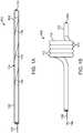
- Fig. 1Aillustrates a variation of a catheter 100 according to the present disclosure.
- Fig. 1Adepicts the catheter 100 in a generally linear configuration; however, the catheter 100 can optionally be configured to be flexible to navigate through tortuous anatomy such as the vasculature and/or other organs throughout the body.
- Fig. 1Ashows the catheter including a distal portion 102 having an optional lumen terminating at a distal end 114 .
- the catheter 100also includes a proximal portion 106 that is used by an operator to manipulate the catheter 100 .
- Variations of the catheter 100can include any number of hubs or handles located towards the proximal end of the proximal portion 106 .
- the catheter 100includes a deflectable section 104 located between the proximal portion 106 and distal portion 102 .
- the deflectable section 104can be actuated by a user via a pull wire 108 or other similar means.
- Variations of the device 100can include a deflectable section 104 that extends along a significant length of the catheter 100 .
- the deflectable section 104includes a cross section that rotates along a length of the deflectable section 104 and as depicted by 118 .
- the rotated cross sectioncomprises at least two different materials that extend helically along a length of the deflectable section 104 .
- Fig. 1Billustrates a proximal force 116 applied to the pull wire 108 to cause the deflectable section 104 to assume a helix or helical profile 110 .
- the rotated cross section of the deflectable section 104results in the helical deflection of the deflectable section 104 upon application of a tensile force on the pull wire 108 that extends through at least a portion of the deflectable section.
- the variation illustrated in Fig. 1Bdemonstrates a helical shape 100 having 4 turns 112 .
- the devices and methods described hereincan include any number of turns 112 as well as alternate helical configurations as shown below.
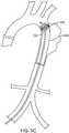
- Fig. 1Cshows a perspective view of a catheter 100 having a deflectable section 104 in a helical profile, as shown the helical profile 110 includes a passage 120 that prevents the catheter 100 from occluding the body lumen when in a helical configuration.
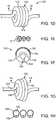
- Fig. 1Dillustrates another variation of a catheter 100 under the present disclosure.
- the deflectable section 104 of the catheter 100can expand.
- Fig. 1Eillustrates a cross sectional view taken along the line 1E-1E in Fig. 1D .
- Fig. IFillustrates a magnified view of the left most turn 112 of the helical profile.
- the catheter 100can include an inflation lumen 150 , a guide wire lumen 152 , and a pull wire 154 or pull wire lumen 154 .
- a variation of the deviceincludes an inflation lumen 150 that is bounded by an expandable material 156 and a flexible material 158 .
- the flexible materialallows for selective flexing of the deformable section 104 while the expandable material 156 expands upon pressurization of the inflation lumen 150 .
- the elastic material 156is oriented such that the material 156 expands outwardly from the helical shape while maintaining the passage 120 so that flow remains through the organ or body lumen.
- the elastic materialcan comprise a material commonly used in medical elastic balloon.
- materials for the support/elastic materialcan include pebax or a mix of pebax and siloxane.
- the elastic materialcan be co-extruded with the flexible material.
- variations of the devicecan include a proximal portion that comprises a stiffer material than the flexible material used in the deflectable section.
- Fig. 1Gillustrates expansion along the deformable section 104 by expanding the elastic material 156 in a direction away from the helical shape.
- the flexible material 158allows for formation of the helical shape but prevents occlusion of the passage 120 .
- Fig. 1Hshows a cross sectional view taken along the line 1H-1H in Fig. 1G .
- the elastic material 156expands away from the helix because the inflation lumen is pressurized (either via a fluid or a gas).
- Fig. 1Halso illustrates the elastic material 158 as allowing for deformation of the deflectable section 104 but also providing a support for the flexible material 156 to expand.
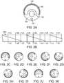
- Fig. 2Aillustrates a cross section of the deformable section 104 as shown in Fig. 1F .
- the inflation lumen 150is bounded by an expandable material 156 and the flexible material 158 .
- the flexible materialallows for selective flexing of the deformable section 104 while the expandable material 156 expands upon pressurization of the inflation lumen 150 .
- the elastic material 156can be oriented such that the material 156 expands outwardly from the helical shape while maintaining the passage 120 so that flow remains through the organ or body lumen.
- the non-expandable portion of the devicecan be fabricated from Peba, Polyurethane , Nylon or a blend of Polyurethane and Siloxane, or Peba and Siloxane, or Nylon and Siloxane.
- the extrusionis processed such that Siloxane is uniformaly dispersed through theother material. By having uniform disbursement of the Siloxane allows for uniform increased lubricity throughout the extrusion.
- Alternate variationsinclude a device fabricated from any commonly known material used in medical device applications.
- Fig. 2Bshows a partial view of a deformable section 104 to illustrate the rotation of the cross section of the deformable section 104 .
- Fig. 2Bshows a number of cross sectional views taken along the lines 2C/2C through 2K/2K.
- the cross sectionrotates along a length of the deflectable section 104 such that the different materials forming the cross section helically rotate along the deflected portion 104 .
- the rate of rotation and/or the length over which the cross section rotatescan be selectively chosen to produce characteristics required for the particular application.
- Figs. 3A to 3Cillustrate variations of the helical shape 110 of various deflectable sections 104 .
- Fig. 3Aillustrates a helical shape having a uniform diameter 170 , 172 between the turns of the helix as well as a uniform pitch 174 .
- Fig. 3Billustrates a varying diameter. In this example, the diameter 174 decreases in a distal direction such that the distal turn has a smaller diameter 176 than the proximal turn.
- Fig. 3Cillustrates a helical shape having varying pitch as measured by distances 178 , 180 , 182 . As shown, the pitch expands in a distal direction. However, the pitch can expand in a proximal direction as well.
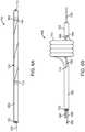
- Fig. 4Aillustrates a variation of a catheter 100 having a single helical turn 112 .
- Fig. 4Billustrates a side view of the catheter 100 of Fig. 4A .
- Fig. 4Cshows the variation of Fig. 4A upon expansion of the elastic material 156 while the flexible material 158 deforms to form the turn 112 and provide support to form the passage 120 .
- Fig. 4Calso shows a guidewire 188 being advanced through a guidewire lumen.
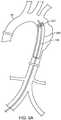
- Figs. 5A to 5Cillustrate one example of a method of using a catheter 100 as described herein.
- a catheter 100is advanced through a vessel 10 or organ (in this variation the vessel comprises an aortic arch).
- the catheter 100can be sized to fit various organs or vessels in the body.
- the catheter 100can optionally be used to expand an implant 200 within the vessel 10 .
- the catheter 100can be used alone to provide an expansion force against the organ or vessel.
- Fig. 5Billustrates transformation of the deflectable section 104 of the catheter 100 into a helix. As shown, this can optionally partially expand the implant 202 for positioning or partial deployment.
- Fig. 5Cshows expansion of the elastic material to fully deploy the implant 202 . As described above, flow continues in the vessel 10 due to the passage in the helical shape.
- Fig. 6Ashows a variation of a device having a guide wire lumen 152 that extends through the device and has multiple openings 114 to allow a guidewire to pass outside of the deflectable section 104 and then reenter the device 100 at an opening 114 in the distal portion 102 so that the guidewire can pass through a distal guidewire opening 114 .
- the guidewire lumen 152can extend adjacent to a pull wire 108 or other similar means in the proximal portion 106 of the device 100 .
- the guidewire lumenexits the device 100 at opening 114 so that the guidewire can exit the device along the deflectable section 104 and then reenter the device at a second opening 114 adjacent to the distal portion 102 of the device.
- This configurationallows the guidewire to extend out of the distal most opening 114 .
- Fig. 6Billustrates a guidewire 188 extending through the device 100 but passing through the helical turns 110 .
- the guidewire 188then re-enters the distal portion 102 of the device 100 so that a physician can navigate the distal portion 102 of the device 100 using the guidewire 188 .
- Figs.7A and 7Bshow another variation of a device 100 having an actuator 194 that allows for expansion of the deflectable section 104 as it forms the helical turns 112 .
- Fig. 7Ashows the device 100 in a linear configuration where a pull wire 108 that extends through the deflectable section 104 also extends proximally and is coupled to the actuator 192 .
- the pull wire 108is coupled to a piston 194 in the actuator 192 .
- the actuator 129is also coupled to a valve 190 (in this variation the valve is a three way valve.
- the valveis also coupled to a fitting 186 of the device 100 . It is noted that the pull wire 108 can be separate from the guide wire that is inserted through the guide wire lumen 152 .
- Fig. 7Brepresents a fluid source being driven through the valve 190 as represented by arrow 210 .
- the fluid 210travels through the device 100 as shown by arrow 212 to expand the expandable area as discussed above.
- the three way valve 190also causes fluid to pressurize the actuator 192 to drive the piston 194 out of the actuator 192 .
- the piston 194is coupled to the pull wire 108 , movement of the piston 194 causes proximal movement of the pull wire as noted by arrow 216 .
- the movement of the pull wirecauses the turns 112 of the deflectable section 104 to form the helical shape.
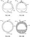
- Figs. 8A-8Dillustrate another aspect for use with the devices described herein.
- the figuresshow a cross sectional view of an expandable section of the device 100 .
- the device 100includes a fluid delivery lumen 162 that permits delivery of a fluid substance from the main body of the catheter.
- Fig. 8Ashows a variation in which a fluid delivery lumen 162 is located in an expandable wall 156 of the device 100 . Alternate variations allow for the fluid delivery lumen 162 to be positioned anywhere within the walls of the device 100 .
- Fig. 8Billustrates a variation of the device 100 with a plurality of fluid delivery lumens 162 . Although not depicted in Figs.
- the fluid delivery lumen 162will have one or more ports that deposit the fluid at a desired location outside the device body 100 .
- Fig. 8Cshow the device 100 in an expanded state where the fluid delivery lumen 162 assumes the shape of an oval without being occluded.
- Fig. 8Dillustrates another variation of a device 100 where the fluid delivery lumen 162 is formed by an expandable section 163 on an exterior of the catheter 100. This configuration allows for a large fluid delivery lumen that can expand to facilitate passage of a fluid.
- the fluid delivery lumen 162will have one or more fluid delivery ports (not shown in Figs. 8A to 8D ) that permit delivery of the fluid when the catheter is in the straight and/or coiled shape.
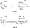
- Fig. 9A and 9Billustrate variations of a device as described herein where one or more fluid ports 128 terminate on an exterior surface of the coiled or helical portion of the device 100 .
- the ports 128which are in fluid communication with the fluid lumen, can be positioned on either side or both sides of the helical turn 112 of the deflectable section 104 . In such a configuration, placing the ports 128 on the sides and/or inside of the helical turn 112 prevents the port 128 from being blocked during expansion of the deflectable section 104 .
- Fig. 9Billustrates another variation of a device 100 having ports 128 . In this variation, the ports 128 are positioned centrally on the turns 128 of the deflectable section 104 .
- FIGS. 9A and 9Balso show the device 100 having any number of hubs 196 , 198 that can be fluidly coupled to the fluid delivery lumen (not shown) such that an external source of fluid can be coupled to the respective hub allowing for delivery of the fluid.
- the portscan be located on additional portions of the catheter, including but not limited to, the non-expanding portion of the catheter.
- Fig. 10illustrates a variation of the device 100 described herein positioned into a coronary artery 14 on a heart 12 where the deflectable section 104 is coiled while allowing blood flow through the coronary vessel 14 .
- the device 100also permits delivery of drugs, medicine or other agents through the ports described above.
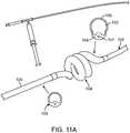
- Figs 11A and 11Bshow additional variations of the device where the helical or deflectable section is joined to a proximal portion 106 and a distal portion 102 such that the deflectable section comprises an elastic material 156 and a flexible material 158 to allow deformation into a helical shape.
- the deflectable section 104can optionally selected to be a clear or semi-clear material.
- Figs. 12A to 12Dshow another example of a device 100 having a feature that aids in the formation of the deflectable section 104 into a helical structure.
- the features and aspects of each example discussed hereincan be combined with other disclosed variations of the device where such features do not conflict.
- the device 100includes a wire 204 (which can be a wire, suture, thread, strand or similar structure) that extends from a proximal end of the device 100 (e.g., through a hub 196 as shown) to a first opening 208 that is located proximally to (or on a proximal end) of the deflectable section 104 .
- the wire 204extends outside of the device along a portion of the deflectable section 104 and re-enters the device 100 a location 218 distal to (or at a distal end of) the deflectable section 104 .
- the wire 204can be fixed at the distal location 218 or can be free floating as long as it can remain within the device a the distal opening 218 .
- FIG. 12Aalso illustrates this variation of the device 100 as having a hub 196 with a locking feature 206 .
- the locking feature 206secures the wire 204 when desired.
- the wire 204can be locked into place using the locking feature 206 to secure the helical shape of the deflectable section.
- the wire 204can be coupled to a piston mechanism as described in Figs. 7A and 7B above.
- FIG. 12Billustrates the deflectable section 104 as it starts to coil.
- the deflectable section 104can being to assume a coil shape using a pull wire or the natural characteristics of the materials forming the device 100 .
- the wire 204remains exterior to the device 100 .
- FIG. 12Cillustrates the wire 204 being drawn to close the distance between the proximal opening 208 and the distal opening 218 . This action permits the deflectable section 104 of the device 100 to form a coiled shape as desired.
- FIG. 12Dillustrates the helical shape of the deformable section 104 when the wire (not shown) secures the helical coil of the device.
- any number of wirescan be used to form additional turns of the device.
- a wirecan pass through any number of turns of the deflectable section 104 .
- the devicecan include a string or other similar member that is attached at a proximal end of the distal tip and extends through the pullwire lumen exiting just where the first balloon loop starts. Then when the catheter forms its fist loop, the string goes back into the lumen. This could be repeated depending on the number of loops of the balloon.
- the stringis external for a few inches (several centimetres) at either one spot along the length of catheter at the loop section, or two spots if it had two loops. The string can be pulled from the back either manually or with the syringe plunger concept that di disclosed above.
Landscapes
- Health & Medical Sciences (AREA)
- Life Sciences & Earth Sciences (AREA)
- Engineering & Computer Science (AREA)
- Biomedical Technology (AREA)
- Heart & Thoracic Surgery (AREA)
- Animal Behavior & Ethology (AREA)
- Veterinary Medicine (AREA)
- Public Health (AREA)
- General Health & Medical Sciences (AREA)
- Pulmonology (AREA)
- Biophysics (AREA)
- Anesthesiology (AREA)
- Hematology (AREA)
- Vascular Medicine (AREA)
- Transplantation (AREA)
- Oral & Maxillofacial Surgery (AREA)
- Child & Adolescent Psychology (AREA)
- Cardiology (AREA)
- Mechanical Engineering (AREA)
- Media Introduction/Drainage Providing Device (AREA)
Description
- There remains a need for a balloon catheter that can be deployed to provide a radial outward force against a body lumen wall without causing occlusion of the body lumen. Such a catheter can be constructed to provide varying expansive characteristics such as a low or high radial outward force, a low or high ratio of expansion, as well as provide the ability to navigate through tortuous anatomy.
US 2011/172697 A1 discloses a medical device, method and system for temporary occlusion of an opening in a lumen of a body. One such device disclosed therein has an extended delivery shape and an expanded shape. The device is brought from the extended delivery shape to the expanded helical shape by drawing a tether line in a proximal direction. The device may comprise an aggregate of a support structure and a balloon.US 2011/0230700 discloses brachytherapy treatment apparatus that include an elongate body including a core member and an outer member surrounding and movable relative to the core member. One or more helical catheters are provided on a distal portion of the elongate body, e.g., including distal ends coupled to the core member and proximal ends coupled to the outer member. The outer member is movable relative to the core member, e.g., axially and/or rotationally, to direct the helical catheters between a collapsed configuration for introduction through a tissue tract to a target location, e.g., a lumpectomy cavity, and an expanded configuration. Each helical catheter includes a lumen, and, after expansion to the expanded configuration, a source of radiation may be introduced along the helical catheters and/or a lumen of the core member for delivering radiation to the target location. Optionally, the apparatus may include a balloon surrounding or within the helical members.- According to an aspect of the present invention there is provided the catheter of claim 1.
- In one variation, the helical profile the flexible support material is located along an internal diameter of the helical profile and the elastic material is located on an external diameter of the helical profile such that upon increasing the pressure within the inflation lumen the elastic material expands radially outward from the helical profile.
- In another variation, the pull wire extends through a pullwire lumen and where the pull wire lumen and inflation lumen are located 180 degrees opposite in the deflectable section cross section.
- Variations of the devices can include a guidewire lumen extending through the proximal portion and flexible support material of the deflectable section. The devices can also optionally include one or more guidewire lumens that extend through a center of the proximal portion, distal portion, and the deflectable section.
- In one example, the guidewire lumen extends through the distal portion.
- The devices can also optionally include an inflation lumen that extends through the proximal portion.
- In variations of the device, a flexible support material durometer is less than a proximal portion durometer.
- The devices can include helical deflectable sections having at least one turn or
a plurality of turns where the helical profile has a pitch and a diameter. - The devices can include variations where at least two turns of the plurality of turns is contiguous along a length of the helical profile. In additional variations, at least two turns of the plurality of turns are spaced and do not touch along a length of the helical profile.
- In some variations, where the pitch of the helical profile is consistent for the plurality of turns. Alternatively, the pitch of the helical profile can vary for the plurality of turns. Furthermore, the diameter of the helical profile can be consistent along a length of the helical profile or can vary.
- The present disclosure also includes methods for performing a medical procedure within a body lumen. In one example such a method includes advancing a catheter into the body lumen, the catheter having a proximal portion, distal portion, and a deflectable section located therebetween, where a deflectable section cross section comprises an elastic material on a first side and a flexible support material on a second side, an inflation lumen bounded by both the elastic material and the flexible support material, and where the deflectable section cross section rotates along a length of the deflectable section such that the elastic material, inflation lumen and flexible support material extend helically along the length of the deflectable section; converting the deflectable section from a near linear shape to a helical shape by applying tension to a pull wire extending through the flexible support material at least along the length of the deflectable section and at least to the proximal portion of the catheter, such that tension in the pull wire causes the deflectable section to deflect into the helical shape; and expanding the elastic material by increasing a pressure within the inflation.
- In another example, the method includes expanding the elastic material by expanding the elastic material against a wall of the body lumen to apply an outward radial force on the wall of the body lumen, while allowing a passage through the helical shape such that the body lumen is not occluded by the catheter.
- In another example, the method can include positioning the deflectable section of the catheter within a second medical device, and where expanding the elastic material causes the second medical device to expand against a wall of the body lumen while allowing a passage through the helical shape such that the body lumen is not occluded by the catheter.
- The present disclosure also includes a catheter having a proximal portion, distal portion, and a deflectable section located therebetween; where a deflectable section cross section comprises an elastic material on a first side and a flexible support material on a second side, an inflation lumen bounded by both the elastic material and the flexible support material, and where the deflectable section cross section has two materials with different Young's modulus along a length of the deflectable section such that the elastic material, inflation lumen and flexible support materials change lengths at different rates during the inflation of the elastic portion of the tubing with the elastic balloon material elongating relative to the flexible support material of the catheter lumen which deflects the deflectable section into a coiled or helical shape that is; cylindrical cone or hooked shaped;
- Such a Young's modulus can optionally be determined by

- Variations of the access device described herein include combinations of features of the various embodiments or combination of the embodiments themselves wherever possible. Methods not being part of the invention and devices described herein provide for improved catheters including those having a deflectable section to allow for expansion while maintaining flow through a vessel. While the following disclosure discusses devices and methods for use in body vessels, such methods and devices can be applied to various body portions.
Fig. 1A illustrates a catheter having a deformable section that can assume a helical configuration.Fig. 1B illustrates a proximal force applied to a pull wire to cause the deflectable section to assume a helix or helical profile.Fig. 1C shows a perspective view of a catheter that is in the helical configuration.Figs. 1D to 1H illustrate an expandable configuration of the catheter's deflectable section.Figs. 2A to 2K show how a cross section of the deflectable section rotates along a length of the deflectable section.Figs. 3A to 3C illustrate additional variations of the helical shapes for use with variations of catheters described herein.Fig. 4A to 4C show a single turn catheter.Figs. 5A to 5C show an example of a catheter with a deformable section being used to deploy a medical device within a body lumen.Figs. 6A and 6B show a variation of the device where a guidewire lumen exits at one side of the deflectable section and reenters the device at a distal section.Figs.7A and 7B show another variation of a device having an actuator that allows for expansion of the deflectable section as it forms the helical turns.Figs. 8A to 8D illustrate variations of devices having fluid delivery lumens .Figs. 9A and 9B show ports on the exterior of the deflectable section.Fig. 10 shows a variation of a device expanded in an artery and delivering a fluid.Figs 11A and11B show additional variations of the device.Figs. 12A to 12D show a variation of a device with an addition wire or suture used to assist the deflectable section when forming a coil or helix.- The following illustrations demonstrate various embodiments and examples of the devices according to the present disclosure. Combinations of aspects of the various devices and methods or combinations of the devices and methods themselves are considered to be within the scope of this disclosure. The disclosure herein relating to methods is of an explanatory nature only.
Fig. 1A illustrates a variation of acatheter 100 according to the present disclosure.Fig. 1A depicts thecatheter 100 in a generally linear configuration; however, thecatheter 100 can optionally be configured to be flexible to navigate through tortuous anatomy such as the vasculature and/or other organs throughout the body.Fig. 1A shows the catheter including adistal portion 102 having an optional lumen terminating at adistal end 114. Thecatheter 100 also includes aproximal portion 106 that is used by an operator to manipulate thecatheter 100. Variations of thecatheter 100 can include any number of hubs or handles located towards the proximal end of theproximal portion 106. Thecatheter 100 includes adeflectable section 104 located between theproximal portion 106 anddistal portion 102. As discussed below, thedeflectable section 104 can be actuated by a user via apull wire 108 or other similar means. Variations of thedevice 100 can include adeflectable section 104 that extends along a significant length of thecatheter 100. Thedeflectable section 104, as described in detail below, includes a cross section that rotates along a length of thedeflectable section 104 and as depicted by118. The rotated cross section comprises at least two different materials that extend helically along a length of thedeflectable section 104.Fig. 1B illustrates aproximal force 116 applied to thepull wire 108 to cause thedeflectable section 104 to assume a helix orhelical profile 110. The rotated cross section of thedeflectable section 104 results in the helical deflection of thedeflectable section 104 upon application of a tensile force on thepull wire 108 that extends through at least a portion of the deflectable section. The variation illustrated inFig. 1B demonstrates ahelical shape 100 having 4 turns112. However, the devices and methods described herein can include any number ofturns 112 as well as alternate helical configurations as shown below.Fig. 1C shows a perspective view of acatheter 100 having adeflectable section 104 in a helical profile, as shown thehelical profile 110 includes apassage 120 that prevents thecatheter 100 from occluding the body lumen when in a helical configuration.Fig. 1D illustrates another variation of acatheter 100 under the present disclosure. In this variation, thedeflectable section 104 of thecatheter 100 can expand.Fig. 1E illustrates a cross sectional view taken along theline 1E-1E inFig. 1D . Fig. IF illustrates a magnified view of the leftmost turn 112 of the helical profile. As shown, thecatheter 100 can include aninflation lumen 150, aguide wire lumen 152, and apull wire 154 or pullwire lumen 154. A variation of the device includes aninflation lumen 150 that is bounded by anexpandable material 156 and aflexible material 158. The flexible material allows for selective flexing of thedeformable section 104 while theexpandable material 156 expands upon pressurization of theinflation lumen 150. In certain variations, theelastic material 156 is oriented such that thematerial 156 expands outwardly from the helical shape while maintaining thepassage 120 so that flow remains through the organ or body lumen.- The elastic material can comprise a material commonly used in medical elastic balloon. Examples of materials for the support/elastic material can include pebax or a mix of pebax and siloxane. The elastic material can be co-extruded with the flexible material. Also, variations of the device can include a proximal portion that comprises a stiffer material than the flexible material used in the deflectable section.
Fig. 1G illustrates expansion along thedeformable section 104 by expanding theelastic material 156 in a direction away from the helical shape. As shown, theflexible material 158 allows for formation of the helical shape but prevents occlusion of thepassage 120.Fig. 1H shows a cross sectional view taken along theline 1H-1H inFig. 1G . As shown, theelastic material 156 expands away from the helix because the inflation lumen is pressurized (either via a fluid or a gas).Fig. 1H also illustrates theelastic material 158 as allowing for deformation of thedeflectable section 104 but also providing a support for theflexible material 156 to expand.Fig. 2A illustrates a cross section of thedeformable section 104 as shown inFig. 1F . Again, theinflation lumen 150 is bounded by anexpandable material 156 and theflexible material 158. The flexible material allows for selective flexing of thedeformable section 104 while theexpandable material 156 expands upon pressurization of theinflation lumen 150. Again, theelastic material 156 can be oriented such that thematerial 156 expands outwardly from the helical shape while maintaining thepassage 120 so that flow remains through the organ or body lumen.- In one example, the non-expandable portion of the device can be fabricated from Peba, Polyurethane , Nylon or a blend of Polyurethane and Siloxane, or Peba and Siloxane, or Nylon and Siloxane. In the variations comprising Peba and Siloxane, or Polyurethan and Siloxane, or Nylon and Siloxane, the extrusion is processed such that Siloxane is uniformaly dispersed through theother material. By having uniform disbursement of the Siloxane allows for uniform increased lubricity throughout the extrusion. Alternate variations include a device fabricated from any commonly known material used in medical device applications.
Fig. 2B shows a partial view of adeformable section 104 to illustrate the rotation of the cross section of thedeformable section 104.Fig. 2B shows a number of cross sectional views taken along thelines 2C/2C through 2K/2K. As shown, the cross section rotates along a length of thedeflectable section 104 such that the different materials forming the cross section helically rotate along the deflectedportion 104. The rate of rotation and/or the length over which the cross section rotates can be selectively chosen to produce characteristics required for the particular application.Figs. 3A to 3C illustrate variations of thehelical shape 110 of variousdeflectable sections 104.Fig. 3A illustrates a helical shape having auniform diameter uniform pitch 174.Fig. 3B illustrates a varying diameter. In this example, thediameter 174 decreases in a distal direction such that the distal turn has asmaller diameter 176 than the proximal turn.Fig. 3C illustrates a helical shape having varying pitch as measured bydistances Fig. 4A illustrates a variation of acatheter 100 having a singlehelical turn 112.Fig. 4B illustrates a side view of thecatheter 100 ofFig. 4A .Fig. 4C shows the variation ofFig. 4A upon expansion of theelastic material 156 while theflexible material 158 deforms to form theturn 112 and provide support to form thepassage 120.Fig. 4C also shows aguidewire 188 being advanced through a guidewire lumen.Figs. 5A to 5C illustrate one example of a method of using acatheter 100 as described herein. As shown inFig. 5A , acatheter 100 is advanced through avessel 10 or organ (in this variation the vessel comprises an aortic arch). However, thecatheter 100 can be sized to fit various organs or vessels in the body. Thecatheter 100 can optionally be used to expand animplant 200 within thevessel 10. Alternatively, thecatheter 100 can be used alone to provide an expansion force against the organ or vessel.Fig. 5B illustrates transformation of thedeflectable section 104 of thecatheter 100 into a helix. As shown, this can optionally partially expand theimplant 202 for positioning or partial deployment.Fig. 5C shows expansion of the elastic material to fully deploy theimplant 202. As described above, flow continues in thevessel 10 due to the passage in the helical shape.Fig. 6A shows a variation of a device having aguide wire lumen 152 that extends through the device and hasmultiple openings 114 to allow a guidewire to pass outside of thedeflectable section 104 and then reenter thedevice 100 at anopening 114 in thedistal portion 102 so that the guidewire can pass through adistal guidewire opening 114. As shown, theguidewire lumen 152 can extend adjacent to apull wire 108 or other similar means in theproximal portion 106 of thedevice 100. However, at or near thedeflectable section 104, the guidewire lumen exits thedevice 100 at opening114 so that the guidewire can exit the device along thedeflectable section 104 and then reenter the device at asecond opening 114 adjacent to thedistal portion 102 of the device. This configuration allows the guidewire to extend out of the distalmost opening 114.Fig. 6B illustrates aguidewire 188 extending through thedevice 100 but passing through the helical turns110. Theguidewire 188 then re-enters thedistal portion 102 of thedevice 100 so that a physician can navigate thedistal portion 102 of thedevice 100 using theguidewire 188.Figs.7A and 7B show another variation of adevice 100 having an actuator194 that allows for expansion of thedeflectable section 104 as it forms the helical turns112.Fig. 7A shows thedevice 100 in a linear configuration where apull wire 108 that extends through thedeflectable section 104 also extends proximally and is coupled to theactuator 192. In this variation, thepull wire 108 is coupled to apiston 194 in theactuator 192. The actuator129 is also coupled to a valve190 (in this variation the valve is a three way valve. The valve is also coupled to a fitting186 of thedevice 100. It is noted that thepull wire 108 can be separate from the guide wire that is inserted through theguide wire lumen 152.Fig. 7B represents a fluid source being driven through thevalve 190 as represented byarrow 210. The fluid210 travels through thedevice 100 as shown byarrow 212 to expand the expandable area as discussed above. However, the threeway valve 190 also causes fluid to pressurize theactuator 192 to drive thepiston 194 out of theactuator 192. Since thepiston 194 is coupled to thepull wire 108, movement of thepiston 194 causes proximal movement of the pull wire as noted byarrow 216. The movement of the pull wire causes theturns 112 of thedeflectable section 104 to form the helical shape.Figs. 8A-8D illustrate another aspect for use with the devices described herein. The figures show a cross sectional view of an expandable section of thedevice 100. In this variation, thedevice 100 includes afluid delivery lumen 162 that permits delivery of a fluid substance from the main body of the catheter.Fig. 8A shows a variation in which afluid delivery lumen 162 is located in anexpandable wall 156 of thedevice 100. Alternate variations allow for thefluid delivery lumen 162 to be positioned anywhere within the walls of thedevice 100.Fig. 8B illustrates a variation of thedevice 100 with a plurality offluid delivery lumens 162. Although not depicted inFigs. 8A-8D , thefluid delivery lumen 162 will have one or more ports that deposit the fluid at a desired location outside thedevice body 100.Fig. 8C show thedevice 100 in an expanded state where thefluid delivery lumen 162 assumes the shape of an oval without being occluded.Fig. 8D illustrates another variation of adevice 100 where thefluid delivery lumen 162 is formed by anexpandable section 163 on an exterior of thecatheter 100. This configuration allows for a large fluid delivery lumen that can expand to facilitate passage of a fluid. Thefluid delivery lumen 162 will have one or more fluid delivery ports (not shown inFigs. 8A to 8D ) that permit delivery of the fluid when the catheter is in the straight and/or coiled shape.Fig. 9A and 9B illustrate variations of a device as described herein where one or morefluid ports 128 terminate on an exterior surface of the coiled or helical portion of thedevice 100. Theports 128, which are in fluid communication with the fluid lumen, can be positioned on either side or both sides of thehelical turn 112 of thedeflectable section 104. In such a configuration, placing theports 128 on the sides and/or inside of thehelical turn 112 prevents theport 128 from being blocked during expansion of thedeflectable section 104.Fig. 9B illustrates another variation of adevice 100 havingports 128. In this variation, theports 128 are positioned centrally on theturns 128 of thedeflectable section 104.Figs. 9A and 9B also show thedevice 100 having any number ofhubs Fig. 10 illustrates a variation of thedevice 100 described herein positioned into acoronary artery 14 on aheart 12 where thedeflectable section 104 is coiled while allowing blood flow through thecoronary vessel 14. Thedevice 100 also permits delivery of drugs, medicine or other agents through the ports described above.Figs 11A and11B show additional variations of the device where the helical or deflectable section is joined to aproximal portion 106 and adistal portion 102 such that the deflectable section comprises anelastic material 156 and aflexible material 158 to allow deformation into a helical shape. As shown, thedeflectable section 104 can optionally selected to be a clear or semi-clear material.Figs. 12A to 12D show another example of adevice 100 having a feature that aids in the formation of thedeflectable section 104 into a helical structure. As with the other variations described herein, the features and aspects of each example discussed herein can be combined with other disclosed variations of the device where such features do not conflict.- As shown in
Fig. 12A , thedevice 100 includes a wire204 (which can be a wire, suture, thread, strand or similar structure) that extends from a proximal end of the device100 (e.g., through ahub 196 as shown) to afirst opening 208 that is located proximally to (or on a proximal end) of thedeflectable section 104. Thewire 204 extends outside of the device along a portion of thedeflectable section 104 and re-enters the device100 alocation 218 distal to (or at a distal end of) thedeflectable section 104. Thewire 204 can be fixed at thedistal location 218 or can be free floating as long as it can remain within the device a thedistal opening 218.FIG. 12A also illustrates this variation of thedevice 100 as having ahub 196 with alocking feature 206. Thelocking feature 206 secures thewire 204 when desired. As discussed below, once the deflectable section is positioned as desired, thewire 204 can be locked into place using thelocking feature 206 to secure the helical shape of the deflectable section. In an additional variation, thewire 204 can be coupled to a piston mechanism as described inFigs. 7A and 7B above. FIG. 12B illustrates thedeflectable section 104 as it starts to coil. As mentioned above, thedeflectable section 104 can being to assume a coil shape using a pull wire or the natural characteristics of the materials forming thedevice 100. As shown, thewire 204 remains exterior to thedevice 100.FIG. 12C illustrates thewire 204 being drawn to close the distance between theproximal opening 208 and thedistal opening 218. This action permits thedeflectable section 104 of thedevice 100 to form a coiled shape as desired.FIG. 12D illustrates the helical shape of thedeformable section 104 when the wire (not shown) secures the helical coil of the device. Although the variation depicted inFIGS. 12A to 12D only coils a single turn of the helical shape, any number of wires can be used to form additional turns of the device. Alternatively, a wire can pass through any number of turns of thedeflectable section 104.- In another variation, the device can include a string or other similar member that is attached at a proximal end of the distal tip and extends through the pullwire lumen exiting just where the first balloon loop starts. Then when the catheter forms its fist loop, the string goes back into the lumen. This could be repeated depending on the number of loops of the balloon. When the catheter is straight before inflation, the string is external for a few inches (several centimetres) at either one spot along the length of catheter at the loop section, or two spots if it had two loops. The string can be pulled from the back either manually or with the syringe plunger concept that di disclosed above.

Claims (15)
- A catheter comprising:a proximal portion (106), a distal portion (102), and a deflectable section (104) located therebetween, the deflectable section (104) having a deflectable cross section;wherein the deflectable cross section comprises an elastic material (156) on a first side and a flexible support material (158) on a second side, an inflation lumen (150) bounded by both the elastic material and the flexible support material, and wherein the deflectable cross section is rotatable along a length of the deflectable section such that the elastic material, the inflation lumen and the flexible support material extend helically along the length of the deflectable section;a pull wire (188) extending through the flexible support material at least along the length of the deflectable section and at least to the proximal portion of the catheter, such that proximal tension applied to the pull wire causes the deflectable section to deflect into a helical profile; andwherein when a pressure within the inflation lumen increases, the elastic material expands away from the inflation lumen.
- The catheter of claim 1, wherein the helical profile the flexible support material is located along an internal diameter of the helical profile and the elastic material is located on an external diameter of the helical profile such that upon increasing the pressure within the inflation lumen the elastic material expands radially outward from the helical profile.
- The catheter of claim 1, wherein the pull wire extends through a pullwire lumen and wherein the pull wire lumen and the inflation lumen are located 180 degrees opposite in the deflectable cross section.
- The catheter of claim 1, further comprising a guidewire lumen extending through the proximal portion and the flexible support material of the deflectable section.
- The catheter of claim 4, wherein the guidewire lumen extends through either:a center of the proximal portion, the distal portion, and the deflectable section; orthe distal portion.
- The catheter of claim 1, wherein the inflation lumen also extends through the proximal portion.
- The catheter of claim 1, wherein a flexible support material durometer is less than a proximal portion durometer.
- The catheter of claim 1, wherein the helical profile comprises at least one turn.
- The catheter of claim 1, wherein the helical profile comprises a plurality of turns and the helical profile has a pitch and a diameter.
- The catheter of claim 9, wherein at least two turns of the plurality of turns is contiguous along a length of the helical profile.
- The catheter of claim 9, wherein at least two turns of the plurality of turns are spaced and do not touch along a length of the helical profile.
- The catheter of claim 9, wherein the pitch of the helical profile is consistent for the plurality of turns.
- The catheter of claim 9, wherein the pitch of the helical profile varies for the plurality of turns.
- The catheter of claim 9, wherein the diameter of the helical profile is consistent along a length of the helical profile.
- The catheter of claim 9, wherein the diameter of the helical profile varies along a length of the helical profile.
Applications Claiming Priority (4)
| Application Number | Priority Date | Filing Date | Title |
|---|---|---|---|
| US201261708524P | 2012-10-01 | 2012-10-01 | |
| US201261724875P | 2012-11-09 | 2012-11-09 | |
| US201261734860P | 2012-12-07 | 2012-12-07 | |
| PCT/US2013/062908WO2014055547A1 (en) | 2012-10-01 | 2013-10-01 | Helical balloon catheter |
Publications (3)
| Publication Number | Publication Date |
|---|---|
| EP2903569A1 EP2903569A1 (en) | 2015-08-12 |
| EP2903569A4 EP2903569A4 (en) | 2016-07-13 |
| EP2903569B1true EP2903569B1 (en) | 2020-12-16 |
Family
ID=50435377
Family Applications (1)
| Application Number | Title | Priority Date | Filing Date |
|---|---|---|---|
| EP13844076.3AActiveEP2903569B1 (en) | 2012-10-01 | 2013-10-01 | Helical balloon catheter |
Country Status (6)
| Country | Link |
|---|---|
| US (4) | US10286184B2 (en) |
| EP (1) | EP2903569B1 (en) |
| JP (3) | JP6347452B2 (en) |
| CN (1) | CN105101914B (en) |
| BR (1) | BR112015007420B1 (en) |
| WO (1) | WO2014055547A1 (en) |
Families Citing this family (23)
| Publication number | Priority date | Publication date | Assignee | Title |
|---|---|---|---|---|
| EP2903569B1 (en) | 2012-10-01 | 2020-12-16 | QMax, LLC | Helical balloon catheter |
| WO2015061801A2 (en) | 2013-10-26 | 2015-04-30 | Accumed Radial Systems Llc | System, apparatus, and method for creating a lumen |
| WO2015160972A1 (en)* | 2014-04-15 | 2015-10-22 | Qmax, Llc | Helical balloon catheter |
| US10729454B2 (en) | 2014-09-10 | 2020-08-04 | Teleflex Life Sciences Limited | Guidewire capture |
| EP3400886B1 (en) | 2014-09-10 | 2019-11-27 | Teleflex Innovations S.à.r.l. | Perfusion catheters |
| CN113521503A (en)* | 2014-12-01 | 2021-10-22 | 帕夫梅德有限公司 | Self-anchoring catheter and method of use |
| GB2538072B (en)* | 2015-05-05 | 2017-11-15 | Strait Access Tech Holdings (Pty) Ltd | A non-occlusive dilation and deployment catheter device |
| JP6709972B2 (en)* | 2016-07-13 | 2020-06-17 | パナソニックIpマネジメント株式会社 | Actuator body, control method thereof, and gripping hand using the same |
| US10245050B2 (en) | 2016-09-30 | 2019-04-02 | Teleflex Innovations S.À.R.L. | Methods for facilitating revascularization of occlusion |
| US10737076B2 (en) | 2016-12-21 | 2020-08-11 | Integra LifeSciences Switzerland Sárl | Self-offsetting implantable catheter system |
| US10905861B2 (en) | 2017-04-25 | 2021-02-02 | Project Moray, Inc. | Matrix supported balloon articulation systems, devices, and methods for catheters and other uses |
| CN107928783B (en)* | 2017-12-29 | 2024-09-06 | 山前(珠海)医疗科技有限公司 | Cryoablation catheter, cryoablation operating device and cryoablation equipment |
| US10918390B2 (en)* | 2018-03-30 | 2021-02-16 | DePuy Synthes Products, Inc. | Helical balloon assist device and method for using the same |
| US10786259B2 (en) | 2018-03-30 | 2020-09-29 | DePuy Synthes Products, Inc. | Split balloon assist device and method for using the same |
| US11027102B2 (en) | 2018-07-20 | 2021-06-08 | Teleflex Life Sciences Limited | Perfusion catheters and related methods |
| WO2020037064A1 (en) | 2018-08-16 | 2020-02-20 | Teleflex Life Sciences Limited | Eluting perfusion catheters |
| WO2020195581A1 (en)* | 2019-03-22 | 2020-10-01 | 国立大学法人滋賀医科大学 | Steerable catheter |
| EP3943139B1 (en)* | 2019-03-22 | 2024-05-08 | National University Corporation Shiga University Of Medical Science | Steerable catheter |
| US11614083B2 (en)* | 2019-09-10 | 2023-03-28 | GM Global Technology Operations LLC | Internally tensioned inflatable structure that is posable in multiple positions |
| US12114920B2 (en)* | 2019-10-22 | 2024-10-15 | Biosense Webster (Israel) Ltd. | Inflatable sleeve multi-electrode catheter |
| US11850385B2 (en) | 2020-04-03 | 2023-12-26 | Covidien Lp | Balloon catheter |
| CN114081566B (en)* | 2021-01-14 | 2025-09-05 | 深圳市蓝藤科技有限公司 | Body cavity regulation device |
| EP4351454A4 (en)* | 2021-06-12 | 2025-07-09 | Tau Medical Inc | ACCESS TO THE INTERVENTRICULAR SEPTUM WITH A PUNCTURE CATHETER DEVICE |
Citations (1)
| Publication number | Priority date | Publication date | Assignee | Title |
|---|---|---|---|---|
| US20110230700A1 (en)* | 2010-03-18 | 2011-09-22 | Cianna Medical, Inc. | Expandable brachytherapy apparatus and methods for using them |
Family Cites Families (32)
| Publication number | Priority date | Publication date | Assignee | Title |
|---|---|---|---|---|
| US4758223A (en)* | 1986-07-02 | 1988-07-19 | Schneider-Shiley (Usa) Inc. | Inflation device for angioplasty catheter |
| US4762130A (en) | 1987-01-15 | 1988-08-09 | Thomas J. Fogarty | Catheter with corkscrew-like balloon |
| US4820298A (en)* | 1987-11-20 | 1989-04-11 | Leveen Eric G | Internal vascular prosthesis |
| US5374261A (en)* | 1990-07-24 | 1994-12-20 | Yoon; Inbae | Multifunctional devices for use in endoscopic surgical procedures and methods-therefor |
| US5181911A (en)* | 1991-04-22 | 1993-01-26 | Shturman Technologies, Inc. | Helical balloon perfusion angioplasty catheter |
| US5370691A (en)* | 1993-01-26 | 1994-12-06 | Target Therapeutics, Inc. | Intravascular inflatable stent |
| WO1994026206A1 (en)* | 1993-05-11 | 1994-11-24 | Target Therapeutics, Inc. | Temporary inflatable intravascular prosthesis |
| US6183491B1 (en)* | 1998-03-10 | 2001-02-06 | Cordis Corporation | Embolic coil deployment system with improved embolic coil |
| JP4397072B2 (en) | 1999-06-30 | 2010-01-13 | 株式会社カネカ | Spiral balloon catheter and method for manufacturing the same |
| US6745080B2 (en)* | 1999-11-22 | 2004-06-01 | Scimed Life Systems, Inc. | Helical and pre-oriented loop structures for supporting diagnostic and therapeutic elements in contact with body tissue |
| CA2391488C (en) | 1999-11-22 | 2012-04-03 | Boston Scientific Limited | Loop structures for supporting diagnostic and therapeutic elements in contact with body tissue |
| US6450988B1 (en)* | 1999-12-29 | 2002-09-17 | Advanced Cardiovascular Systems, Inc. | Centering catheter with improved perfusion |
| US6482221B1 (en)* | 2000-08-21 | 2002-11-19 | Counter Clockwise, Inc. | Manipulatable delivery catheter for occlusive devices (II) |
| US6409652B1 (en)* | 2000-09-20 | 2002-06-25 | Vascular Architects, Inc. | Device and method for delivery of uniform and controlled radiation dose to blood vessels |
| US6679860B2 (en)* | 2001-06-19 | 2004-01-20 | Medtronic Ave, Inc. | Intraluminal therapy catheter with inflatable helical member and methods of use |
| US6923808B2 (en)* | 2003-02-24 | 2005-08-02 | Boston Scientific Scimed, Inc. | Probes having helical and loop shaped inflatable therapeutic elements |
| DE102005034529A1 (en)* | 2005-07-23 | 2007-01-25 | Qualimed Innovative Medizinprodukte Gmbh | balloon dilatation catheter |
| US8956400B2 (en)* | 2005-10-14 | 2015-02-17 | Flexible Stenting Solutions, Inc. | Helical stent |
| EP2074826A4 (en)* | 2006-10-11 | 2011-11-09 | Nokia Corp | DISCOVERING SERVICES IN BROADCAST NETWORKS |
| EP2134405B1 (en) | 2007-03-27 | 2021-06-02 | Intratech Medical Ltd. | Spiral balloon catheter |
| WO2009121017A1 (en)* | 2008-03-27 | 2009-10-01 | The Regents Of The University Of California | Balloon catheter for reducing restenosis via irreversible electroporation |
| US20090264770A1 (en) | 2008-04-17 | 2009-10-22 | Omnisonics Medical Technologies, Inc. | Medical Systems and Related Methods |
| WO2010029190A1 (en) | 2008-09-15 | 2010-03-18 | Joensson Anders | Medical device, method and system for temporary occlusion of an opening in a lumen of a body |
| WO2010041038A1 (en) | 2008-10-10 | 2010-04-15 | Veryan Medical Limited | A medical device |
| US9597214B2 (en)* | 2008-10-10 | 2017-03-21 | Kevin Heraty | Medical device |
| US9033916B2 (en)* | 2009-08-28 | 2015-05-19 | Biosense Webster, Inc. | Catheter with multi-functional control handle having rotational mechanism |
| EP2501431B1 (en)* | 2009-11-19 | 2020-01-08 | Wellinq Medical B.V. | Narrow profile composition-releasing expandable medical balloon catheter |
| CA2804254C (en)* | 2010-02-23 | 2016-11-01 | Medina Medical, Inc. | Devices and methods for vascular recanalization |
| US8840542B2 (en)* | 2010-06-10 | 2014-09-23 | Myriad Medical, Llc | Intracavity balloon catheter |
| KR101912960B1 (en)* | 2010-10-25 | 2018-10-29 | 메드트로닉 아르디언 룩셈부르크 에스에이알엘 | Catheter Appratuses having Multi-Electrode Arrays for Renal Neuromodulation and Associated Systems and Methods |
| US9220433B2 (en)* | 2011-06-30 | 2015-12-29 | Biosense Webster (Israel), Ltd. | Catheter with variable arcuate distal section |
| EP2903569B1 (en) | 2012-10-01 | 2020-12-16 | QMax, LLC | Helical balloon catheter |
- 2013
- 2013-10-01EPEP13844076.3Apatent/EP2903569B1/enactiveActive
- 2013-10-01BRBR112015007420-0Apatent/BR112015007420B1/enactiveIP Right Grant
- 2013-10-01USUS14/043,608patent/US10286184B2/enactiveActive
- 2013-10-01JPJP2015535743Apatent/JP6347452B2/enactiveActive
- 2013-10-01CNCN201380062857.XApatent/CN105101914B/ennot_activeExpired - Fee Related
- 2013-10-01WOPCT/US2013/062908patent/WO2014055547A1/enactiveApplication Filing
- 2018
- 2018-05-23JPJP2018098597Apatent/JP7106354B2/enactiveActive
- 2019
- 2019-03-26USUS16/364,591patent/US11324923B2/enactiveActive
- 2021
- 2021-04-28JPJP2021076077Apatent/JP7319320B2/enactiveActive
- 2022
- 2022-05-03USUS17/661,886patent/US12070562B2/enactiveActive
- 2024
- 2024-07-15USUS18/773,258patent/US20240366917A1/enactivePending
Patent Citations (1)
| Publication number | Priority date | Publication date | Assignee | Title |
|---|---|---|---|---|
| US20110230700A1 (en)* | 2010-03-18 | 2011-09-22 | Cianna Medical, Inc. | Expandable brachytherapy apparatus and methods for using them |
Also Published As
| Publication number | Publication date |
|---|---|
| CN105101914B (en) | 2017-03-29 |
| US20220257906A1 (en) | 2022-08-18 |
| BR112015007420A2 (en) | 2017-07-04 |
| US20240366917A1 (en) | 2024-11-07 |
| HK1217894A1 (en) | 2017-01-27 |
| JP2018161485A (en) | 2018-10-18 |
| BR112015007420B1 (en) | 2021-06-22 |
| US10286184B2 (en) | 2019-05-14 |
| JP7319320B2 (en) | 2023-08-01 |
| WO2014055547A1 (en) | 2014-04-10 |
| JP6347452B2 (en) | 2018-06-27 |
| JP2015530223A (en) | 2015-10-15 |
| US20140249506A1 (en) | 2014-09-04 |
| EP2903569A1 (en) | 2015-08-12 |
| US20190314610A1 (en) | 2019-10-17 |
| JP7106354B2 (en) | 2022-07-26 |
| CN105101914A (en) | 2015-11-25 |
| EP2903569A4 (en) | 2016-07-13 |
| JP2021176508A (en) | 2021-11-11 |
| US12070562B2 (en) | 2024-08-27 |
| US11324923B2 (en) | 2022-05-10 |
Similar Documents
| Publication | Publication Date | Title |
|---|---|---|
| US12070562B2 (en) | Helical balloon catheter | |
| US11707607B2 (en) | Helical balloon catheter | |
| US10583273B2 (en) | Tip propelled device for motion through a passage | |
| JP5758626B2 (en) | Catheter apparatus for treating vasculature | |
| JP5453299B2 (en) | Drug delivery catheter having an inflatable communication portion between two axially spaced balloons | |
| US6494905B1 (en) | Balloon catheter | |
| JP2011505918A5 (en) | ||
| CN101854871A (en) | Captive coil for treating body lumens | |
| EP1417984A2 (en) | Balloon catheter | |
| HK1217894B (en) | Helical balloon catheter | |
| EP2977071A1 (en) | Supportive balloon catheter | |
| JPH07299145A (en) | Medical guidewire |
Legal Events
| Date | Code | Title | Description |
|---|---|---|---|
| PUAI | Public reference made under article 153(3) epc to a published international application that has entered the european phase | Free format text:ORIGINAL CODE: 0009012 | |
| 17P | Request for examination filed | Effective date:20150430 | |
| AK | Designated contracting states | Kind code of ref document:A1 Designated state(s):AL AT BE BG CH CY CZ DE DK EE ES FI FR GB GR HR HU IE IS IT LI LT LU LV MC MK MT NL NO PL PT RO RS SE SI SK SM TR | |
| AX | Request for extension of the european patent | Extension state:BA ME | |
| DAX | Request for extension of the european patent (deleted) | ||
| REG | Reference to a national code | Ref country code:DE Ref legal event code:R079 Ref document number:602013074790 Country of ref document:DE Free format text:PREVIOUS MAIN CLASS: A61F0002958000 Ipc:A61M0025100000 | |
| RA4 | Supplementary search report drawn up and despatched (corrected) | Effective date:20160613 | |
| RIC1 | Information provided on ipc code assigned before grant | Ipc:A61M 25/01 20060101ALN20160607BHEP Ipc:A61M 25/10 20060101AFI20160607BHEP Ipc:A61F 2/958 20130101ALI20160607BHEP Ipc:A61M 25/00 20060101ALI20160607BHEP | |
| STAA | Information on the status of an ep patent application or granted ep patent | Free format text:STATUS: EXAMINATION IS IN PROGRESS | |
| 17Q | First examination report despatched | Effective date:20181218 | |
| GRAP | Despatch of communication of intention to grant a patent | Free format text:ORIGINAL CODE: EPIDOSNIGR1 | |
| STAA | Information on the status of an ep patent application or granted ep patent | Free format text:STATUS: GRANT OF PATENT IS INTENDED | |
| INTG | Intention to grant announced | Effective date:20200630 | |
| GRAS | Grant fee paid | Free format text:ORIGINAL CODE: EPIDOSNIGR3 | |
| GRAA | (expected) grant | Free format text:ORIGINAL CODE: 0009210 | |
| STAA | Information on the status of an ep patent application or granted ep patent | Free format text:STATUS: THE PATENT HAS BEEN GRANTED | |
| AK | Designated contracting states | Kind code of ref document:B1 Designated state(s):AL AT BE BG CH CY CZ DE DK EE ES FI FR GB GR HR HU IE IS IT LI LT LU LV MC MK MT NL NO PL PT RO RS SE SI SK SM TR | |
| REG | Reference to a national code | Ref country code:GB Ref legal event code:FG4D | |
| REG | Reference to a national code | Ref country code:IE Ref legal event code:FG4D | |
| REG | Reference to a national code | Ref country code:DE Ref legal event code:R096 Ref document number:602013074790 Country of ref document:DE | |
| REG | Reference to a national code | Ref country code:AT Ref legal event code:REF Ref document number:1345035 Country of ref document:AT Kind code of ref document:T Effective date:20210115 | |
| PG25 | Lapsed in a contracting state [announced via postgrant information from national office to epo] | Ref country code:NO Free format text:LAPSE BECAUSE OF FAILURE TO SUBMIT A TRANSLATION OF THE DESCRIPTION OR TO PAY THE FEE WITHIN THE PRESCRIBED TIME-LIMIT Effective date:20210316 Ref country code:FI Free format text:LAPSE BECAUSE OF FAILURE TO SUBMIT A TRANSLATION OF THE DESCRIPTION OR TO PAY THE FEE WITHIN THE PRESCRIBED TIME-LIMIT Effective date:20201216 Ref country code:RS Free format text:LAPSE BECAUSE OF FAILURE TO SUBMIT A TRANSLATION OF THE DESCRIPTION OR TO PAY THE FEE WITHIN THE PRESCRIBED TIME-LIMIT Effective date:20201216 Ref country code:GR Free format text:LAPSE BECAUSE OF FAILURE TO SUBMIT A TRANSLATION OF THE DESCRIPTION OR TO PAY THE FEE WITHIN THE PRESCRIBED TIME-LIMIT Effective date:20210317 | |
| REG | Reference to a national code | Ref country code:AT Ref legal event code:MK05 Ref document number:1345035 Country of ref document:AT Kind code of ref document:T Effective date:20201216 | |
| REG | Reference to a national code | Ref country code:NL Ref legal event code:MP Effective date:20201216 | |
| PG25 | Lapsed in a contracting state [announced via postgrant information from national office to epo] | Ref country code:BG Free format text:LAPSE BECAUSE OF FAILURE TO SUBMIT A TRANSLATION OF THE DESCRIPTION OR TO PAY THE FEE WITHIN THE PRESCRIBED TIME-LIMIT Effective date:20210316 Ref country code:SE Free format text:LAPSE BECAUSE OF FAILURE TO SUBMIT A TRANSLATION OF THE DESCRIPTION OR TO PAY THE FEE WITHIN THE PRESCRIBED TIME-LIMIT Effective date:20201216 Ref country code:LV Free format text:LAPSE BECAUSE OF FAILURE TO SUBMIT A TRANSLATION OF THE DESCRIPTION OR TO PAY THE FEE WITHIN THE PRESCRIBED TIME-LIMIT Effective date:20201216 | |
| PG25 | Lapsed in a contracting state [announced via postgrant information from national office to epo] | Ref country code:NL Free format text:LAPSE BECAUSE OF FAILURE TO SUBMIT A TRANSLATION OF THE DESCRIPTION OR TO PAY THE FEE WITHIN THE PRESCRIBED TIME-LIMIT Effective date:20201216 Ref country code:HR Free format text:LAPSE BECAUSE OF FAILURE TO SUBMIT A TRANSLATION OF THE DESCRIPTION OR TO PAY THE FEE WITHIN THE PRESCRIBED TIME-LIMIT Effective date:20201216 | |
| REG | Reference to a national code | Ref country code:LT Ref legal event code:MG9D | |
| PG25 | Lapsed in a contracting state [announced via postgrant information from national office to epo] | Ref country code:PT Free format text:LAPSE BECAUSE OF FAILURE TO SUBMIT A TRANSLATION OF THE DESCRIPTION OR TO PAY THE FEE WITHIN THE PRESCRIBED TIME-LIMIT Effective date:20210416 Ref country code:SK Free format text:LAPSE BECAUSE OF FAILURE TO SUBMIT A TRANSLATION OF THE DESCRIPTION OR TO PAY THE FEE WITHIN THE PRESCRIBED TIME-LIMIT Effective date:20201216 Ref country code:RO Free format text:LAPSE BECAUSE OF FAILURE TO SUBMIT A TRANSLATION OF THE DESCRIPTION OR TO PAY THE FEE WITHIN THE PRESCRIBED TIME-LIMIT Effective date:20201216 Ref country code:LT Free format text:LAPSE BECAUSE OF FAILURE TO SUBMIT A TRANSLATION OF THE DESCRIPTION OR TO PAY THE FEE WITHIN THE PRESCRIBED TIME-LIMIT Effective date:20201216 Ref country code:SM Free format text:LAPSE BECAUSE OF FAILURE TO SUBMIT A TRANSLATION OF THE DESCRIPTION OR TO PAY THE FEE WITHIN THE PRESCRIBED TIME-LIMIT Effective date:20201216 Ref country code:CZ Free format text:LAPSE BECAUSE OF FAILURE TO SUBMIT A TRANSLATION OF THE DESCRIPTION OR TO PAY THE FEE WITHIN THE PRESCRIBED TIME-LIMIT Effective date:20201216 Ref country code:EE Free format text:LAPSE BECAUSE OF FAILURE TO SUBMIT A TRANSLATION OF THE DESCRIPTION OR TO PAY THE FEE WITHIN THE PRESCRIBED TIME-LIMIT Effective date:20201216 | |
| PG25 | Lapsed in a contracting state [announced via postgrant information from national office to epo] | Ref country code:PL Free format text:LAPSE BECAUSE OF FAILURE TO SUBMIT A TRANSLATION OF THE DESCRIPTION OR TO PAY THE FEE WITHIN THE PRESCRIBED TIME-LIMIT Effective date:20201216 Ref country code:AT Free format text:LAPSE BECAUSE OF FAILURE TO SUBMIT A TRANSLATION OF THE DESCRIPTION OR TO PAY THE FEE WITHIN THE PRESCRIBED TIME-LIMIT Effective date:20201216 | |
| REG | Reference to a national code | Ref country code:DE Ref legal event code:R097 Ref document number:602013074790 Country of ref document:DE | |
| PG25 | Lapsed in a contracting state [announced via postgrant information from national office to epo] | Ref country code:IS Free format text:LAPSE BECAUSE OF FAILURE TO SUBMIT A TRANSLATION OF THE DESCRIPTION OR TO PAY THE FEE WITHIN THE PRESCRIBED TIME-LIMIT Effective date:20210416 | |
| PLBE | No opposition filed within time limit | Free format text:ORIGINAL CODE: 0009261 | |
| STAA | Information on the status of an ep patent application or granted ep patent | Free format text:STATUS: NO OPPOSITION FILED WITHIN TIME LIMIT | |
| PG25 | Lapsed in a contracting state [announced via postgrant information from national office to epo] | Ref country code:AL Free format text:LAPSE BECAUSE OF FAILURE TO SUBMIT A TRANSLATION OF THE DESCRIPTION OR TO PAY THE FEE WITHIN THE PRESCRIBED TIME-LIMIT Effective date:20201216 | |
| 26N | No opposition filed | Effective date:20210917 | |
| PG25 | Lapsed in a contracting state [announced via postgrant information from national office to epo] | Ref country code:DK Free format text:LAPSE BECAUSE OF FAILURE TO SUBMIT A TRANSLATION OF THE DESCRIPTION OR TO PAY THE FEE WITHIN THE PRESCRIBED TIME-LIMIT Effective date:20201216 Ref country code:ES Free format text:LAPSE BECAUSE OF FAILURE TO SUBMIT A TRANSLATION OF THE DESCRIPTION OR TO PAY THE FEE WITHIN THE PRESCRIBED TIME-LIMIT Effective date:20201216 | |
| PG25 | Lapsed in a contracting state [announced via postgrant information from national office to epo] | Ref country code:SI Free format text:LAPSE BECAUSE OF FAILURE TO SUBMIT A TRANSLATION OF THE DESCRIPTION OR TO PAY THE FEE WITHIN THE PRESCRIBED TIME-LIMIT Effective date:20201216 | |
| REG | Reference to a national code | Ref country code:DE Ref legal event code:R119 Ref document number:602013074790 Country of ref document:DE | |
| REG | Reference to a national code | Ref country code:CH Ref legal event code:PL | |
| PG25 | Lapsed in a contracting state [announced via postgrant information from national office to epo] | Ref country code:IS Free format text:LAPSE BECAUSE OF FAILURE TO SUBMIT A TRANSLATION OF THE DESCRIPTION OR TO PAY THE FEE WITHIN THE PRESCRIBED TIME-LIMIT Effective date:20210416 | |
| REG | Reference to a national code | Ref country code:BE Ref legal event code:MM Effective date:20211031 | |
| GBPC | Gb: european patent ceased through non-payment of renewal fee | Effective date:20211001 | |
| PG25 | Lapsed in a contracting state [announced via postgrant information from national office to epo] | Ref country code:MC Free format text:LAPSE BECAUSE OF FAILURE TO SUBMIT A TRANSLATION OF THE DESCRIPTION OR TO PAY THE FEE WITHIN THE PRESCRIBED TIME-LIMIT Effective date:20201216 | |
| PG25 | Lapsed in a contracting state [announced via postgrant information from national office to epo] | Ref country code:LU Free format text:LAPSE BECAUSE OF NON-PAYMENT OF DUE FEES Effective date:20211001 Ref country code:GB Free format text:LAPSE BECAUSE OF NON-PAYMENT OF DUE FEES Effective date:20211001 Ref country code:BE Free format text:LAPSE BECAUSE OF NON-PAYMENT OF DUE FEES Effective date:20211031 Ref country code:DE Free format text:LAPSE BECAUSE OF NON-PAYMENT OF DUE FEES Effective date:20220503 | |
| PG25 | Lapsed in a contracting state [announced via postgrant information from national office to epo] | Ref country code:LI Free format text:LAPSE BECAUSE OF NON-PAYMENT OF DUE FEES Effective date:20211031 Ref country code:CH Free format text:LAPSE BECAUSE OF NON-PAYMENT OF DUE FEES Effective date:20211031 | |
| PG25 | Lapsed in a contracting state [announced via postgrant information from national office to epo] | Ref country code:FR Free format text:LAPSE BECAUSE OF NON-PAYMENT OF DUE FEES Effective date:20211031 | |
| PG25 | Lapsed in a contracting state [announced via postgrant information from national office to epo] | Ref country code:HU Free format text:LAPSE BECAUSE OF FAILURE TO SUBMIT A TRANSLATION OF THE DESCRIPTION OR TO PAY THE FEE WITHIN THE PRESCRIBED TIME-LIMIT; INVALID AB INITIO Effective date:20131001 | |
| PG25 | Lapsed in a contracting state [announced via postgrant information from national office to epo] | Ref country code:CY Free format text:LAPSE BECAUSE OF FAILURE TO SUBMIT A TRANSLATION OF THE DESCRIPTION OR TO PAY THE FEE WITHIN THE PRESCRIBED TIME-LIMIT Effective date:20201216 | |
| PG25 | Lapsed in a contracting state [announced via postgrant information from national office to epo] | Ref country code:MK Free format text:LAPSE BECAUSE OF FAILURE TO SUBMIT A TRANSLATION OF THE DESCRIPTION OR TO PAY THE FEE WITHIN THE PRESCRIBED TIME-LIMIT Effective date:20201216 | |
| PG25 | Lapsed in a contracting state [announced via postgrant information from national office to epo] | Ref country code:MT Free format text:LAPSE BECAUSE OF FAILURE TO SUBMIT A TRANSLATION OF THE DESCRIPTION OR TO PAY THE FEE WITHIN THE PRESCRIBED TIME-LIMIT Effective date:20201216 | |
| PGFP | Annual fee paid to national office [announced via postgrant information from national office to epo] | Ref country code:IE Payment date:20240930 Year of fee payment:12 | |
| PGFP | Annual fee paid to national office [announced via postgrant information from national office to epo] | Ref country code:IT Payment date:20240930 Year of fee payment:12 |