EP2902552B1 - Wear member for excavating equipment - Google Patents
Wear member for excavating equipmentDownload PDFInfo
- Publication number
- EP2902552B1 EP2902552B1EP15151947.7AEP15151947AEP2902552B1EP 2902552 B1EP2902552 B1EP 2902552B1EP 15151947 AEP15151947 AEP 15151947AEP 2902552 B1EP2902552 B1EP 2902552B1
- Authority
- EP
- European Patent Office
- Prior art keywords
- wear member
- lock
- stabilizing
- accordance
- socket
- Prior art date
- Legal status (The legal status is an assumption and is not a legal conclusion. Google has not performed a legal analysis and makes no representation as to the accuracy of the status listed.)
- Active
Links
Images


Classifications
- E—FIXED CONSTRUCTIONS
- E02—HYDRAULIC ENGINEERING; FOUNDATIONS; SOIL SHIFTING
- E02F—DREDGING; SOIL-SHIFTING
- E02F9/00—Component parts of dredgers or soil-shifting machines, not restricted to one of the kinds covered by groups E02F3/00 - E02F7/00
- E02F9/28—Small metalwork for digging elements, e.g. teeth scraper bits
- E02F9/2808—Teeth
- E02F9/2816—Mountings therefor
- E02F9/2833—Retaining means, e.g. pins
- B—PERFORMING OPERATIONS; TRANSPORTING
- B23—MACHINE TOOLS; METAL-WORKING NOT OTHERWISE PROVIDED FOR
- B23P—METAL-WORKING NOT OTHERWISE PROVIDED FOR; COMBINED OPERATIONS; UNIVERSAL MACHINE TOOLS
- B23P11/00—Connecting or disconnecting metal parts or objects by metal-working techniques not otherwise provided for
- E—FIXED CONSTRUCTIONS
- E02—HYDRAULIC ENGINEERING; FOUNDATIONS; SOIL SHIFTING
- E02F—DREDGING; SOIL-SHIFTING
- E02F9/00—Component parts of dredgers or soil-shifting machines, not restricted to one of the kinds covered by groups E02F3/00 - E02F7/00
- E02F9/28—Small metalwork for digging elements, e.g. teeth scraper bits
- E02F9/2808—Teeth
- E02F9/2816—Mountings therefor
- E02F9/2825—Mountings therefor using adapters
- E—FIXED CONSTRUCTIONS
- E02—HYDRAULIC ENGINEERING; FOUNDATIONS; SOIL SHIFTING
- E02F—DREDGING; SOIL-SHIFTING
- E02F9/00—Component parts of dredgers or soil-shifting machines, not restricted to one of the kinds covered by groups E02F3/00 - E02F7/00
- E02F9/28—Small metalwork for digging elements, e.g. teeth scraper bits
- E02F9/2808—Teeth
- E02F9/2816—Mountings therefor
- E02F9/2833—Retaining means, e.g. pins
- E02F9/2841—Retaining means, e.g. pins resilient
- E—FIXED CONSTRUCTIONS
- E02—HYDRAULIC ENGINEERING; FOUNDATIONS; SOIL SHIFTING
- E02F—DREDGING; SOIL-SHIFTING
- E02F9/00—Component parts of dredgers or soil-shifting machines, not restricted to one of the kinds covered by groups E02F3/00 - E02F7/00
- E02F9/28—Small metalwork for digging elements, e.g. teeth scraper bits
- E02F9/2866—Small metalwork for digging elements, e.g. teeth scraper bits for rotating digging elements
- E—FIXED CONSTRUCTIONS
- E02—HYDRAULIC ENGINEERING; FOUNDATIONS; SOIL SHIFTING
- E02F—DREDGING; SOIL-SHIFTING
- E02F9/00—Component parts of dredgers or soil-shifting machines, not restricted to one of the kinds covered by groups E02F3/00 - E02F7/00
- E02F9/28—Small metalwork for digging elements, e.g. teeth scraper bits
- E02F9/2875—Ripper tips
- E—FIXED CONSTRUCTIONS
- E02—HYDRAULIC ENGINEERING; FOUNDATIONS; SOIL SHIFTING
- E02F—DREDGING; SOIL-SHIFTING
- E02F9/00—Component parts of dredgers or soil-shifting machines, not restricted to one of the kinds covered by groups E02F3/00 - E02F7/00
- E02F9/28—Small metalwork for digging elements, e.g. teeth scraper bits
- E02F9/2883—Wear elements for buckets or implements in general
- E—FIXED CONSTRUCTIONS
- E02—HYDRAULIC ENGINEERING; FOUNDATIONS; SOIL SHIFTING
- E02F—DREDGING; SOIL-SHIFTING
- E02F9/00—Component parts of dredgers or soil-shifting machines, not restricted to one of the kinds covered by groups E02F3/00 - E02F7/00
- E02F9/28—Small metalwork for digging elements, e.g. teeth scraper bits
- E02F9/2891—Tools for assembling or disassembling
- Y—GENERAL TAGGING OF NEW TECHNOLOGICAL DEVELOPMENTS; GENERAL TAGGING OF CROSS-SECTIONAL TECHNOLOGIES SPANNING OVER SEVERAL SECTIONS OF THE IPC; TECHNICAL SUBJECTS COVERED BY FORMER USPC CROSS-REFERENCE ART COLLECTIONS [XRACs] AND DIGESTS
- Y10—TECHNICAL SUBJECTS COVERED BY FORMER USPC
- Y10T—TECHNICAL SUBJECTS COVERED BY FORMER US CLASSIFICATION
- Y10T29/00—Metal working
- Y10T29/49—Method of mechanical manufacture
- Y10T29/49826—Assembling or joining
Definitions
- the present inventionpertains to a wear assembly for securing a wear member to excavating equipment.
- Wear partsare commonly attached to excavating equipment, such as excavating buckets or cutterheads, to protect the equipment from wear and to enhance the digging operation.
- the wear partsmay include excavating teeth, shrouds, etc.
- Such wear partstypically include a base, a wear member, and a lock to releasably hold the wear member to the base.
- the baseincludes a forwardly projecting nose for supporting the wear member.
- the basemay be formed as an integral part of the digging edge or may be formed as one or more adapters that are fixed to the digging edge by welding or mechanical attachment.
- the wear memberis a point which fits over the nose. The point narrows to a front digging edge for penetrating and breaking up the ground.
- the assembled nose and pointcooperatively define an opening into which the lock is received to releasably hold the point to the nose.
- Such wear membersare commonly subjected to harsh conditions and heavy loading. Accordingly, the wear members wear out over a period of time and need to be replaced. Many designs have been developed in an effort to enhance the strength, stability, durability, penetration, safety, and/or ease of replacement of such wear members with varying degrees of success.
- WO 02/04750discloses a tooth assembly including an adapter and a replaceable tip.
- the tiphas a socket and rearward ears to resist the loads applied during use.
- the present inventionpertains to an improved wear assembly for securing wear members to excavating equipment for enhanced stability, strength, durability, penetration, safety, and ease of replacement.
- the present inventionpertains to a wear assembly 10 for releasably attaching a wear member 12 to excavating equipment (not shown).
- wear member 12is described in terms of a point for an excavating tooth that is attached to a lip of an excavating bucket.
- the wear membercould be in the form of other kinds of wear parts (e.g., shrouds) or attached to other excavating equipment (e.g., dredge cutterheads).
- relative termssuch as forward, rearward, up, down, horizontal or vertical are used for convenience of explanation with reference to the orientation of the assembly in Figure 1 ; other orientations are possible.
- the wear member or point 12is adapted to fit on a nose 14.
- the noseis the front portion of a base 15 that is fixed to a bucket (not shown) or other equipment.
- the rear mounting portion 19 of base 15can be fixed to the bucket in a number of common ways.
- base 15includes a pair of rearward legs 21 ( Figs. 1-3 ) that extend over and are welded to the lip of a bucket. Nevertheless, the base can include only one leg, be cast as part of the lip, or be mechanically fixed to the bucket lip, such as by a Whisler-style lock.
- the baseis typically called an adapter.
- the basecan also consist of a plurality of interconnected adapters. Wear member 12 is releasably secured to nose 14 by a lock 17.
- Nose 14includes a body 18 and a front end 20 ( Figs. 3-11 ).
- the front end 20preferably has a generally triangular shape with a horizontal lower surface 22 and a pair of inclined surfaces 24 facing upward and outward, collectively defining an inverted V-shape.
- the lower and upper surfaces 22, 24are front stabilizing surfaces that are substantially parallel to the longitudinal axis 26 of the nose.
- the term "substantially parallel”is intended to include parallel surfaces as well as surfaces that diverge rearwardly from axis 26 at a small angle (e.g., of about 1-7 degrees) for manufacturing or other purposes. A small divergence may also ease removal of the wear member from the nose.
- each stabilizing surface 22, 24diverges rearwardly at an angle of no more than about 5 degrees and most preferably about 2-3 degrees to axis 26.
- upper surfaces 24are preferably more horizontal-than-vertical, i.e., at an angle ⁇ between 0 and 45 degrees relative to lower surface 22, and most preferably at an angle ⁇ of about 40 degrees ( Fig. 9 ). Nevertheless, inclinations outside the preferred range are possible, particularly in light duty operations or in environments where high side loading can occur.
- Lower surface 22is provided to resist upward vertical loading.
- a triangularly-shaped front end(along with other parts of the nose) also ensures that wear member 12 will be mounted properly on the nose, i.e., the wear member cannot be mounted the wrong way on the nose.
- the nose and socketcan be formed to optimize shape for a given application.
- the nosemay be formed with a profile for greater penetration, a shape that reduces the rate of wear on the wear member, and an efficient construction to specially suit loads and wear patterns expected in the desired digging operations.
- This reduced profile at its lateral endsreduces the wearing and stress on the upper lateral ends of the socket and nose compared to conventional teeth. As a result, the usable lives of the wear member and the nose are Increased.
- the triangular front end 20 of nose 14defines a smaller profile for better penetration into the ground. The use of inclined surfaces at the upper corners allows the wear member to be shaped such that more surface area is available to carry earthen materials into the bucket.
- front stabilizing end 20preferably has a triangular shape formed by upper and lower surfaces 22, 24, other configurations with inclined side surfaces can be used to reduce the lateral projection of the upper front corners.
- the inclined sidewallsmay define a generally trapezoidal shape.
- the upper cornersmay be chamfered to shift the upper corners inward. The chamfers may be made so as to eliminate the sidewalls and/or top walls or to connect the side and top walls.
- the inclined surfacesmay be curved to define, for example, a generally hemispherically shaped front end.
- a triangular shaped front end 20 or other front end shapes with inclined sidewallscould be used in connection with other known nose configurations.
- a front endcould be used as a stabilizing front end instead of the stabilizing front end disclosed on the nose in U.S. Patent No. 5,709,043 .
- the front endcould be reversed for digging operations where the loads and wear would be expected to be along the bottom side as opposed to the top side of the wear assembly.
- Pose 14is further defined in part by an upper wall 31 and a lower wall 33 ( Figs. 3 and 10 ).
- Upper and lower walls 31, 33converge toward front thrust surface 27 to form the common wedge shape to provide a compromise of strength and the ability to penetrate.
- the central portion 34 of upper wall 31continues to converge toward lower wall 33 through front end 20 to the thrust surface 27 for a slimmer outer profile and enhanced penetration without sacrificing stability. This continued tapering of upper wall 31 through front end 20 and the accompanying slimming of the nose is possible because of the use of the inclined stabilizing surfaces 24 to provide the stabilizing support.
- upper wall 31 and a lower wall 33that are each inclined to diverge away from axis 26 in a rearward direction.
- upper wall 31has a more shallow inclination relative to axis 26 than lower wall 33.
- nose 14transitions rearwardly from a relatively small sized front end 20 with facets 22, 24 for high penetration and stability into a larger sized rear end with increased facets for strength and support ( Figs. 3-11 ).
- the nosechanges from a generally triangular front end into a six-faceted body, which in turn transitions into an eight-faceted body at its rear end.
- nose 14transitions from a three or four-faceted surface at the front end (depending on whether central facet 34 maintains a significant width in front end 20) into a six-faceted surface into body 18 for strength, stability and a slimmer profile.
- Body 18preferably comprises an upper central facet 34 and a pair of inclined side facets 36, and a lower central facet 38 and inclined side facets 40 to present a strong profile.
- the use of central facets 34, 38reduces the overall depth of the assembly to provide a more slender projection for better penetration.
- the top central facet 34is preferably flat in a transverse direction with a width that expands rearwardly to ease the flow of earthen material into the bucket.
- the lower central facet 38is also generally flat in a transverse direction, but preferably has a narrowing width in a rearward direction. This is particularly beneficial on account of the greater inclination of lower side 33 as compared to upper side 31. While planar facets 34, 36, 38, 40 are preferred, curved facets could also be used. Nevertheless, other shapes and arrangements where the nose changes from a relatively small sized front end with a certain facets into a larger sized rear end with increased facets are possible.
- Lower side facets 40are preferably substantially parallel to axis 26 to define rear stabilizing surfaces ( Figs. 5 , 7 , 8 and 9 ). As with front stabilizing surfaces 24, rear stabilizing surfaces 40 are laterally inclined to resist both vertical and side loading. The inclination of stabilizing surfaces 40 should be chosen as a balance between stabilizing the wear member under vertical loading and providing the assembly with sufficient overall strength. Accordingly, side facets 40 are preferably inclined relative to central facet 38 at an angle ⁇ between 105 and 180 degrees, and most preferably at an angle of about 128 degrees ( Fig. 11 ). Nevertheless, stabilizing surfaces 40 could be inclined outside of the preferred range, particularly in light duty operations or those involving high side loading. The rearward narrowing of central facet 38 also maximizes the rearward expansion of stabilizing surfaces 40 to provide greater surface area for resisting loads, particularly at the rear of nose 14.
- body 25transitions into an eight-faceted structure at its rear end 41 ( Figs. 4, 5 , 7 and 8 ).
- nose 14further includes a pair of opposite, vertically positioned side surfaces 43 to reduce the profile of the nose for better penetration and to provide additional support to resist side loads.
- the first front phaseincludes four facets
- the middle phase rearward of the front stabilizing endincludes six facets
- the rear phasedefines eight facets rearward of the lock (though it could extend forward of the lock if desired).
- facet 34does not extend through the front end 20
- the first phasewould have three facets. In either case, the front end 20 is considered to be generally triangular.
- Base 15further includes supports 42 adjacent nose 14 for additional stabilization of wear member 12 under upwardly directed loads ( Figs. 4-9 ).
- supports 42are substantially parallel to axis 26 and oriented generally in a horizontal orientation, though they could be laterally inclined to resist both vertical and side loads.
- One support 42sets to each side of nose 14 just below the intersection of facets 36, 40, although they could be at or just above the intersection.
- upper stabilizing surfaces 42are laterally offset from lower stabilizing surfaces 40. This offset, juxtaposed relationship of the lower and upper stabilizing surfaces 40, 42 on base 15 enables the use of a more slender tooth system than if upper facets 36 were designed to be stabilizing surfaces that, for example, mirror lower facets 40.
- supports 42provide stabilization against upward loads
- upper facets 36are inclined in both axial and lateral directions, without defining stabilization surfaces substantially parallel to axis 26. With this construction, side facets 36 avoid extending farther upward and impeding the flow of earthen material into the bucket. Nevertheless, facets 36 could be formed as stabilizing surfaces with or without supports 42, or other arrangements of stabilizing surfaces could be used. Moreover, since supports 42 are preferably structured to resist only vertical loading, a single support on one side could be provided if desired.
- Wear member 12includes a bit 28 with a front digging edge 44 and a mounting end 46 with a rearwardly-opening socket 16 ( Figs. 1-3 and 12-17 ).
- Socket 16is preferably formed to matingly receive nose 14, although differences between the nose and socket could exist.
- socket 16preferably includes a generally triangular-shaped stabilizing front end 48 having a lower stabilizing surface 52 and a pair of upper stabilizing surfaces 54 ( Fig. 14 ). Stabilizing surfaces 52, 54 are substantially parallel to axis 26.
- socket 16transitions into a larger main portion 56 defined by an upper side 58 and a lower side 60.
- Upper side 58includes a top facet 64 and side facets 66 to correspond to facets 34, 36 on nose 14.
- lower side 60includes a bottom facet 68 and side facets 70 to correspond to facets 38, 40 on nose 14.
- Side facets 70are also substantially parallel to longitudinal axis 26 to bear against side facets 40 under certain loads.
- Side surfaces 71are also provided to bear against side surfaces 43.
- Mounting end 46further includes shoulders 72 formed by an offset portion 74 of upper side 58 that overhangs past the rear end of lower side 60 ( Figs 1 , 2 , 12 and 14-17 ).
- Shoulders 72are substantially parallel to axis 26 and oriented generally horizontal to bear against supports 42.
- Shoulders 72are integral with upper side 58 rather than extending rearwardly like known cantilevered ears. This arrangement, then, as compared to cantilevered ears, provides shoulders 72 with greater support and requires the use of less metal. Nevertheless, it is possible to provide ears to bear against supports 42.
- stabilizing surfaces 22, 24, 40, 42, 52, 54, 70, 72are intended to be the primary surfaces for resisting vertical and side loads that are applied to the wear member.
- loads having vertical componentsare applied along the digging edge 44 of wear member 12
- the wear memberis urged to roll forward off the nose.
- wear member 12is urged to roll forward on nose 14 such that front stabilizing surfaces 54 in socket 16 bear against stabilizing surfaces 24 at the front end of nose 14.
- the rear end 79 of lower side 60 of wear member 12is also drawn upward against the lower side 33 of nose 14 such that rear stabilizing surfaces 70 in socket 16 bear against stabilizing surfaces 40 of nose 14.
- stabilizing surfaces 40, 70provides more stable support for the point as compared to the use of conventional converging surfaces, with less reliance on the lock. For instance, if load L1 is applied to a tooth with a nose and socket defined by converging top and bottom walls without stabilizing surfaces 40, 70, the urge to roll the wear member off the nose is resisted in part by the abutting of converging walls at the rear ends of the nose and socket. Since these converging walls are axially inclined to the longitudinal axis, their abutment with each other urges the point in a forward direction, which must be resisted by the lock. Accordingly, in such known constructions, a larger lock is needed to hold the point to the nose.
- a larger lockrequires larger openings in the nose and point, thus, reducing the overall strength of the assembly.
- stabilizing surfaces 40, 70are substantially parallel to longitudinal axis 26 to minimize forward urging of wear member 12. As a result, the wear member is stably supported on the nose to increase the strength and stability of the assembly, reduce wear, and enable the use of smaller locks.
- Stabilizing surfaces 22, 42, 52, 72function in essentially the same manner for upwardly-directed vertical loads.
- An upwardly directed load L2( Fig. 1 ) causes front stabilizing surface 52 of socket 16 to bear against stabilizing surface 22 on the front end of nose 14.
- the upward rolling of wear member 12 on nose 14is also resisted by shoulders 72 bearing against supports 42 at the rear ends of wear member 12 and nose 14.
- These stabilizing surfaces 22, 42, 52, 72can have a smaller surface than stabilizing surfaces 40, 70 because the bulk of the loads are expected to be rearward and downward.
- stabilizing surfaces 24, 40, 54, 70are inclined in transverse directions. Preferably, these angled stabilizing surfaces are symmetrical, although an asymmetrical arrangement is possible.
- the transverse inclination of stabilizing surfaces 24, 40, 54, 70enables them to resist side loads, such as load L3 ( Fig. 1 ).
- side loadssuch as load L3 ( Fig. 1 ).
- the application of side load L3causes wear member 12 to laterally cant on nose 14.
- the front stabilizing surface 54 on the side L3is applied is pushed laterally inward to bear against front stabilizing surface 24 on nose 14.
- the rear portion 79 of facet 70 on the opposite sidewall of socket 16is drawn inward to bear against the corresponding facet 40.
- the opposite stabilizing surfaces 24, 54, 40, 70work in the same way for oppositely directed side loads.
- Stabilizing surfaces 22, 42, 52, 72are not inclined in the preferred embodiment because the bulk of the loads are expected to be rearward and downward, and the use of horizontal stabilizing surfaces in this direction enables the design of an assembly with less depth.
- Stabilizing surfaces 22, 24, 40, 42, 52, 54, 70, 72are preferably planar, but could have different shapes.
- the stabilizing surfacescould be formed with broad convex or concave curves.
- rear stabilizing surfaces 40, 70are generally most effective when located at or near the rear end of the nose and socket.
- the front portions of stabilizing surfaces 40, 70taper to a front point.
- the front portionscould have other narrowing shapes, non-converging shapes, or be eliminated entirely. Further, bearing may occur on only one portion of any or all of the stabilizing surfaces.
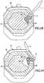
- lock 17fits into an opening in the form of through-hole 81 defined in wear member 12 and a pocket or cavity 83 defined in one side of nose 14 ( Figs. 1-2 ).
- Lock 17is movable between a hold position ( Figs. 1 , 2 and 30 ) where the lock 17 holds wear member 12 to nose 14, and a release position ( Figs. 31 and 32 ) where wear member 12 can be installed on or removed from nose 14.
- Through-hole 81preferably extends through a side facet 66 ( Figs. 1 , 2 and 12-16 ), but could be formed in other parts of the wear member.
- Through-hole 81has a generally rectangular shape with two end walls 85, 87, front wall 89 and rear wall 91, but could have other shapes.
- One end wall 85defines a pivot member 93 in the form of a rounded bulb ( Fig. 16 ).
- the bulb 93is preferably turned inward, toward nose 14, to alleviate the risk of wearing the bulb away.
- Bulb 93defines an axis that extends generally in a longitudinal direction relative to the wear assembly and is structured such that loading is minimized during use.
- the opposite end wall 87defines a stop 95 in the form of a projection extending generally toward end wall 85.
- Rear wall 91preferably includes an expanded portion 91a that extends into socket 16 to provide a larger bearing face for the lock and to move the bearing moment inward to reduce the tendency of the wear member 12 to cant on base 15 due to the lock securing only one side.
- Nose 14includes recess 94 to accommodate the presence of the inward extension of rear wall 91.
- Lock 17( Figs. 18-22 ) includes a narrow end 103, a wide end 105, a front face 107, and a rear face 109, though other shapes are possible.
- Narrow end 103is formed as a pivot member 113, which preferably defines an arcuate recess to cooperate with bulb 93 on end wall 85 to enable the lock to pivotally swing between hold and release positions.
- Pivot members 93, 113could be reversed so that the bulb is formed on lock 17 and the recess on wear member 12, or have a different construction that defines the pivot axis.
- Wide end 105includes a latch formation 115 that cooperates with end wall 87 to retain lock 17 in hold and release positions.
- pivot member 93could be formed on end wall 87 and the latch formation 115 adapted to engage end wall 85, they are preferably as illustrated to minimize obstructions with adjacent wear assemblies during installation or release.
- lock 17is composed of a body 110, a resilient member 112 and a shield 114 all bonded or otherwise secured together.
- Body 110defines latch formation 115 that engages end wall 87 and stop 95.
- Shield 114overlies resilient member 112 to engage bulb 93.
- Resilient member 112provides lock 17 with a resilient compressibility.
- Cavity 83 in nose 14is preferably defined by base walls 129, 131 collectively having a generally L-shaped configuration, a front wall 133, and a rear wall 135 ( Figs. 4 , 6 , 7 and 8 ). Since cavity 83 does not extend through nose 14, it retains more of the nose strength.
- Base wall 129provides a platform against which lock 17 can set to prevent excessive insertion.
- Base wall 131is preferably curved to follow the arcuate path of lock 17 when swung into the hold position.
- Lock 17fits into through-hole 81 such that pivot member 113 bears against bulb 93 for pivotal movement of the lock between the hold position and the release position ( Figs. 23-32 ).
- lock 17is swung about bulb 93 to fit fully within cavity 83.
- a tool Tis used to move the lock into the hold position; i.e., tool T is placed into a slot 132 ( Figs. 12 and 13 ) in bulb 93 and used to pry lock 17 into the hold position ( Figs. 23-25 ).
- the toolis able to force fingers 116 past end wall 87 adjacent stop 95 with the compression of resilient member 112.
- fingers 116opposes facet 66 in socket 16 to prevent movement of lock 17 away from the hold position.
- end wall 87operates as catch for lock 17.
- lock 17preferably has two spaced apart fingers 116, a single finger 116 could be used.
- a recess 134is preferably provided in outer surface 125 of wear member 12 to accommodate the desired movement of tool T. However, other prying arrangements could be used.
- latch formation 115includes fingers 116 that set behind facet 66 to prevent release of the lock from the assembly; resilient member 112 biases finger 116 behind facet 66 after insertion of lock 17 (although lock 17 is preferably not tight against end wall 87).
- the outer face 123 of lock 17is generally aligned with or slightly recessed relative to the outer surface 125 of wear member 12 ( Fig. 30 ). In this way, the lock is partially protected from wearing and forms no obstruction to the flow of earthen material into the bucket.
- Lock 17further includes a recess 120 along wide end 105. Notch 120 receives stop 95 to hold lock 17 in its release position ( Figs. 23 , 31 and 32 ); resilient member 112 releasably holds the lock in this position.
- a protrusion 120apreferably extends outward at the distal end of recess 120 to prevent lock 17 from moving out of through-hole 81. In the preferred construction, lock 17 never needs to be removed from through-hole 81 in wear member 12. Lock 17 is installed into wear member 12 (in the release position) at the time of manufacture and shipped to a customer ( Fig. 30a ). The customer stores the wear member with the lock in it until needed for use.
- a depression 130is preferably provided in nose 14 to accommodate passage of lock 17 in its release position during installation of the combined wear member and lock ( Figs. 4 and 7 ).
- a relief 130ais also preferable provided to permit passage of bulb 93 during installation of point. Then, the lock is swung to its hold position to secure wear member 12 to base 15 ( Fig. 30 ).
- This arrangementreduces shipping and storage costs, virtually eliminates losing the locks in storage or at the installation site in the field, and eases the installation process. Nevertheless, lock 17 could be completely removed from wear member 12 if desired for shipping, storage, replacement, installation and/or removal.
- lock 17is placed in the hold position to secure wear member 12 to base 15.
- Lock 17is preferably shipped and/or stored in combination with wear member 12 in the release position without base 15.
- Lock 17could be structured to store and/or ship in the hold position or some rearward position if desired.
- Lock 17preferably includes abutments 128 that prevent lock 17 from falling through through-hole 81 and into socket 16 when nose 14 is absent.
- Lock 17further includes notches 122, 124, 126 which are provided to aid removal of lock 17 from the assembly ( Figs. 18 and 22 ).
- a tool Tis used to engage notches 122, 124, 126 ( Figs. 26-29 ) as needed to pivot lock 17 from the hold position to the release position.
- the toolis initially placed in notch 126 ( Fig. 26 ) and moved using stop 95 as a fulcrum to bias lock 17 toward bulb 93 against the bias of resilient member 112 ( Fig. 27 ) and to swing lock 17 outward such that fingers 116 swing past end wall 87 and set outside of the through-hole 81 ( Fig. 28 ).
- tool Tis placed successively within notches 124 and 122 to swing lock 17 to the release position.
- the successive notchesare for better leverage and ease of use.
- front and rear faces 107, 109 of lock 17are generally parallel to the opposed front and rear walls 133, 135 of pocket 83. In this way, a firm engagement can be had between the lock and the pocket. Nevertheless, in an alternative construction, faces 107 and 109 of lock 17 converge toward inner side 149 to engage similarly converging walls 133, 135 of pocket 83. In this way, the lock can be more easily inserted and removed from pocket 83 as the walls do not engage until fully positioned.
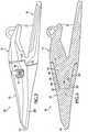
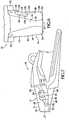
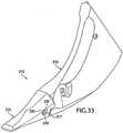
- wear assembly 210is shown as a tooth for a ripper machine ( Figs. 33-37 ).
- the wear assemblyincludes a wear member 212 in the form of a point, a base 215 adapted to be fixed to a ripper arm, and a lock 217 to secure wear member 212 to base 215.
- Base 215includes a nose 214 which is received in socket 216 in wear member 212.
- the configurations of nose 214 and socket 216are generally the same as nose 14 and socket 16 discussed above in regard to wear assembly 10. Nevertheless, there can be some changes, as illustrated, such as the omission of the formations related to the locking arrangement and the omission of side surfaces 43, 71. There can also be relative changes to the dimensions of the various surfaces.
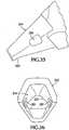
- Nose 214 and socket 216each includes a generally triangular front end 220, which transitions rearwardly into a six-faceted structure. In the illustrated example, the nose and socket do not later transition into an eight-faceted structure as in wear assembly 10 (though it could if desired).
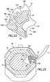
- lock 217includes a wedge 230 and a spool 231 such as disclosed in U.S. Patent No. 7,174,661 , herein incorporated by reference.
- Wedge 230has a conical shape and a thread formation in the form of a helical groove 234 ( Figs. 34 and 37 ).
- Spool 231includes a pair of arms 236 and a body 238 interconnecting the arms.
- Body 238defines a trough 240 in which is received wedge 230.
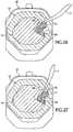
- Trough 240includes spaced helical ridges 242 for receipt within groove 234. In this way, wedge 230 is threaded to spool 231 so that it can be drawn into the assembly by turning the wedge with a wrench or other tool.
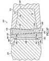
- Hole 283extends horizontally through a mid-section of nose 214 to receive lock 217 ( Fig. 33 ), but could extend vertically or diagonally.
- Wear member 212defines a pair of through-holes 281 which generally align with hole 283 when nose 214 is fully received into socket 216 ( Figs. 33-37 ).
- Through-holes 281 and hole 283collectively define an opening 285 to receive lock 217.
- Arms 236abut against the rear ends 290 of through-holes 281 while wedge 230 bears against the front wall 292 of hole 283.
- Arms 236each preferably includes a lip 294 to set within a relief 296 defined in wear member 212 to prevent inadvertent ejection of lock 217 during use ( Fig. 37 ).
- lock 17could be reversed such that the spool (without arms) engaged front wall 292 and the wedge engaged rear ends 290.
- wear member 212is placed over nose 214 so that through-holes 281 generally align with hole 283 to collectively define opening 285.
- Lock 217is placed into opening 285 with the arms 236 abutting against rear ends 290 of through-holes 281 and wedge 230 being loosely received into trough 240.
- Wedge 230is rotated such that the receipt of ridges 242 in helical groove 234 pulls the wedge farther into opening 285 until the lock has firmly secured wear member 212 to base 215.
Landscapes
- Engineering & Computer Science (AREA)
- Mining & Mineral Resources (AREA)
- Civil Engineering (AREA)
- General Engineering & Computer Science (AREA)
- Structural Engineering (AREA)
- Mechanical Engineering (AREA)
- Component Parts Of Construction Machinery (AREA)
- Earth Drilling (AREA)
- Socks And Pantyhose (AREA)
Description
- The present invention pertains to a wear assembly for securing a wear member to excavating equipment.
- Wear parts are commonly attached to excavating equipment, such as excavating buckets or cutterheads, to protect the equipment from wear and to enhance the digging operation. The wear parts may include excavating teeth, shrouds, etc. Such wear parts typically include a base, a wear member, and a lock to releasably hold the wear member to the base.
- In regard to excavating teeth, the base includes a forwardly projecting nose for supporting the wear member. The base may be formed as an integral part of the digging edge or may be formed as one or more adapters that are fixed to the digging edge by welding or mechanical attachment. The wear member is a point which fits over the nose. The point narrows to a front digging edge for penetrating and breaking up the ground. The assembled nose and point cooperatively define an opening into which the lock is received to releasably hold the point to the nose.
- Such wear members are commonly subjected to harsh conditions and heavy loading. Accordingly, the wear members wear out over a period of time and need to be replaced. Many designs have been developed in an effort to enhance the strength, stability, durability, penetration, safety, and/or ease of replacement of such wear members with varying degrees of success.
WO 02/04750 - The present invention is as defined in claim 1 below. Optional features of the invention are set out in the dependent claims.
- The present invention pertains to an improved wear assembly for securing wear members to excavating equipment for enhanced stability, strength, durability, penetration, safety, and ease of replacement.
Figure 1 is a perspective view of a wear assembly in accordance with the present invention.Figure 2 is a side view of the wear assembly.Figure 3 is a cross-sectional view of the wear assembly vertically taken along the longitudinal axis.Figure 4 is an upper perspective view of a base of the wear assembly.Figure 5 is a lower perspective view of the nose of the base.Figure 6 is a top view of the nose.Figure 7 is a side view of the base.Figure 8 is a side view of the nose.Figure9 is a front view of the base.Figure 10 is a cross-sectional view of the base taken along such section line 10-10 inFigure 9 .Figure 11 is a cross-sectional view of the base taken along such section line 11-11 inFigure 8 .Figure 12 is a perspective view of a wear member of the wear assembly.Figure 13 is an enlarged view of the part of the wear member within the circle c inFigure 12 .Figure 14 is a rear view of the wear member.Figure 15 is a side view of the wear member.Figure 16 is a cross-sectional view taken along section line 16-16 inFigure 14 .Figure 17 is a cross-sectional view taken along section line 17-17 inFigure 14 .Figures 18 and 19 are each a perspective view of a lock for the wear assembly.Figure 20 is a front view of the lock.Figure 21 is a side view of the lock.Figure 22 is a cross-sectional view taken along line 22-22 inFigure 21 .Figures 23-25 are transverse cross-section views showing the incremental installation of the lock into the wear assembly with a pry tool.Figures 26-29 are transverse cross-sectional views showing the incremental removal of the lock from the wear assembly with a pry tool.Figure 30 is an enlarged, transverse cross-sectional view of the wear assembly with the lock in the hold position in the assembly.Figure 30a is an enlarged, transverse cross-sectional view of the wear member combined with the lock in the hold position.Figure 31 is a perspective view of the wear member with the lock in the release position.Figure 32 is an enlarged transverse cross-sectional view of the lock in the release position.Figure 33 is a perspective view of a second embodiment of a wear assembly in accordance with the present invention.Figure 34 is an exploded perspective view of the second embodiment.Figure 35 is a side view of the nose of the second embodiment.Figure 36 is a rear view of the wear member of the second embodiment.Figure 37 is a partial cross-sectional view taken vertically along the longitudinal axis.- The present invention pertains to a
wear assembly 10 for releasably attaching awear member 12 to excavating equipment (not shown). In this application,wear member 12 is described in terms of a point for an excavating tooth that is attached to a lip of an excavating bucket. However, the wear member could be in the form of other kinds of wear parts (e.g., shrouds) or attached to other excavating equipment (e.g., dredge cutterheads). Moreover, relative terms such as forward, rearward, up, down, horizontal or vertical are used for convenience of explanation with reference to the orientation of the assembly inFigure 1 ; other orientations are possible. - In one embodiment (
Figs. 1-32 ), the wear member orpoint 12 is adapted to fit on anose 14. The nose is the front portion of abase 15 that is fixed to a bucket (not shown) or other equipment. Therear mounting portion 19 ofbase 15 can be fixed to the bucket in a number of common ways. In the illustrated example,base 15 includes a pair of rearward legs 21 (Figs. 1-3 ) that extend over and are welded to the lip of a bucket. Nevertheless, the base can include only one leg, be cast as part of the lip, or be mechanically fixed to the bucket lip, such as by a Whisler-style lock. When the base is secured to the lip by welding or a locking mechanism, the base is typically called an adapter. The base can also consist of a plurality of interconnected adapters.Wear member 12 is releasably secured tonose 14 by alock 17. Nose 14 includes abody 18 and a front end 20 (Figs. 3-11 ). Thefront end 20 preferably has a generally triangular shape with a horizontallower surface 22 and a pair ofinclined surfaces 24 facing upward and outward, collectively defining an inverted V-shape. The lower andupper surfaces longitudinal axis 26 of the nose. The term "substantially parallel" is intended to include parallel surfaces as well as surfaces that diverge rearwardly fromaxis 26 at a small angle (e.g., of about 1-7 degrees) for manufacturing or other purposes. A small divergence may also ease removal of the wear member from the nose. In one preferred embodiment, each stabilizingsurface axis 26.- It is common in digging operations for the teeth to be forced forward and upward through the ground. As a result, the primary directions in which excavating teeth are commonly loaded are rearward and downward.
Front face 27 ofnose 14 abutsfront surface 29 insocket 16 to primarily resist rearward loads. Upper stabilizingsurfaces 24 are substantially parallel toaxis 26 to provide stable resistance to downwardly applied vertical loads on the front end ofwear member 12. Also, due to irregularities in the ground, rocks, and other impediments, the teeth also tend to experience side loads as well as loads that shift. Upper stabilizingsurfaces 24 are inclined to resist both downward vertical loads and side loads. Loads that shift between vertical and side loads are also better resisted by the sameupper surfaces 24 to reduce shifting ofwear member 12 onnose 14, and thereby reduce wearing of the components. The larger surface area provided by both angledupper surfaces 24 as compared tolower surface 22 can also provide a benefit in resisting the expected larger downward loads. - Since vertical loading is typically greater than side loading,
upper surfaces 24 are preferably more horizontal-than-vertical, i.e., at an angle θ between 0 and 45 degrees relative tolower surface 22, and most preferably at an angle θ of about 40 degrees (Fig. 9 ). Nevertheless, inclinations outside the preferred range are possible, particularly in light duty operations or in environments where high side loading can occur.Lower surface 22 is provided to resist upward vertical loading. - A triangularly-shaped front end (along with other parts of the nose) also ensures that
wear member 12 will be mounted properly on the nose, i.e., the wear member cannot be mounted the wrong way on the nose. Moreover, since the wear member is not subject to reversible mounting, the nose and socket can be formed to optimize shape for a given application. As example, the nose may be formed with a profile for greater penetration, a shape that reduces the rate of wear on the wear member, and an efficient construction to specially suit loads and wear patterns expected in the desired digging operations. - In an effort to stabilize the mounting of the wear member, it has been known to form the front end of the nose and socket as mating parallelepipeds with rectangular shaped stabilizing surfaces. At times, the wear member can thin causing high stress which may lead to failure or wear through the wear member to expose the nose at the corners, which in either case results in the wear member needing to be replaced before the
bit portion 28 has worn away. Since downward loading is typically greater than upward loading and with the flow of earthen material into the bucket, such break through usually occurs along the top of the wear member. With an upward-pointing, triangularly-shaped front stabilizing end fornose 14,upper surfaces 24 are inclined downwardly, in a lateral direction, to shift the upper front corners of the stabilization end to a central position (Figs. 4, 5 and9 ). This reduced profile at its lateral ends, in turn, reduces the wearing and stress on the upper lateral ends of the socket and nose compared to conventional teeth. As a result, the usable lives of the wear member and the nose are Increased. In addition, the triangularfront end 20 ofnose 14 defines a smaller profile for better penetration into the ground. The use of inclined surfaces at the upper corners allows the wear member to be shaped such that more surface area is available to carry earthen materials into the bucket. - While
front stabilizing end 20 preferably has a triangular shape formed by upper andlower surfaces - Moreover, a triangular shaped
front end 20 or other front end shapes with inclined sidewalls could be used in connection with other known nose configurations. As an example only, such a front end could be used as a stabilizing front end instead of the stabilizing front end disclosed on the nose inU.S. Patent No. 5,709,043 . In addition, the front end could be reversed for digging operations where the loads and wear would be expected to be along the bottom side as opposed to the top side of the wear assembly. Pose 14 is further defined in part by anupper wall 31 and a lower wall 33 (Figs. 3 and10 ). Upper andlower walls front thrust surface 27 to form the common wedge shape to provide a compromise of strength and the ability to penetrate. However, unlike the common nose formed with front stabilizing surfaces, thecentral portion 34 ofupper wall 31 continues to converge towardlower wall 33 throughfront end 20 to thethrust surface 27 for a slimmer outer profile and enhanced penetration without sacrificing stability. This continued tapering ofupper wall 31 throughfront end 20 and the accompanying slimming of the nose is possible because of the use of the inclined stabilizingsurfaces 24 to provide the stabilizing support.- As discussed above,
upper wall 31 and alower wall 33 that are each inclined to diverge away fromaxis 26 in a rearward direction. To reduce obstructions and enhance flow of earthen material into the bucket,upper wall 31 has a more shallow inclination relative toaxis 26 thanlower wall 33. Further,nose 14 transitions rearwardly from a relatively small sizedfront end 20 withfacets Figs. 3-11 ). In the illustrated embodiment, the nose changes from a generally triangular front end into a six-faceted body, which in turn transitions into an eight-faceted body at its rear end. - In a preferred construction,
nose 14 transitions from a three or four-faceted surface at the front end (depending on whethercentral facet 34 maintains a significant width in front end 20) into a six-faceted surface intobody 18 for strength, stability and a slimmer profile.Body 18 preferably comprises an uppercentral facet 34 and a pair ofinclined side facets 36, and a lowercentral facet 38 andinclined side facets 40 to present a strong profile. The use ofcentral facets central facet 34 is preferably flat in a transverse direction with a width that expands rearwardly to ease the flow of earthen material into the bucket. The lowercentral facet 38 is also generally flat in a transverse direction, but preferably has a narrowing width in a rearward direction. This is particularly beneficial on account of the greater inclination oflower side 33 as compared toupper side 31. Whileplanar facets Lower side facets 40 are preferably substantially parallel toaxis 26 to define rear stabilizing surfaces (Figs. 5 ,7 ,8 and 9 ). As with front stabilizingsurfaces 24,rear stabilizing surfaces 40 are laterally inclined to resist both vertical and side loading. The inclination of stabilizingsurfaces 40 should be chosen as a balance between stabilizing the wear member under vertical loading and providing the assembly with sufficient overall strength. Accordingly,side facets 40 are preferably inclined relative tocentral facet 38 at an angle Φ between 105 and 180 degrees, and most preferably at an angle of about 128 degrees (Fig. 11 ). Nevertheless, stabilizingsurfaces 40 could be inclined outside of the preferred range, particularly in light duty operations or those involving high side loading. The rearward narrowing ofcentral facet 38 also maximizes the rearward expansion of stabilizingsurfaces 40 to provide greater surface area for resisting loads, particularly at the rear ofnose 14.- In a preferred embodiment, body 25 transitions into an eight-faceted structure at its rear end 41 (
Figs. 4, 5 ,7 and8 ). In the illustrated example,nose 14 further includes a pair of opposite, vertically positioned side surfaces 43 to reduce the profile of the nose for better penetration and to provide additional support to resist side loads. The use of a nose and socket which transitions through three phases, each having more facets than the more forward phases (excluding surfaces pertaining to the lock or those of ridges and grooves), provides an advantageous combination of strength and slenderness for improved operation and penetration. In a preferred example, the first front phase includes four facets, the middle phase rearward of the front stabilizing end includes six facets, and the rear phase defines eight facets rearward of the lock (though it could extend forward of the lock if desired). Alternatively, iffacet 34 does not extend through thefront end 20, then the first phase would have three facets. In either case, thefront end 20 is considered to be generally triangular. Base 15 further includessupports 42adjacent nose 14 for additional stabilization ofwear member 12 under upwardly directed loads (Figs. 4-9 ). In a preferred construction, supports 42 are substantially parallel toaxis 26 and oriented generally in a horizontal orientation, though they could be laterally inclined to resist both vertical and side loads. Onesupport 42 sets to each side ofnose 14 just below the intersection offacets surfaces 42 are laterally offset from lower stabilizing surfaces 40. This offset, juxtaposed relationship of the lower and upper stabilizingsurfaces base 15 enables the use of a more slender tooth system than ifupper facets 36 were designed to be stabilizing surfaces that, for example, mirrorlower facets 40. Sincesupports 42 provide stabilization against upward loads,upper facets 36 are inclined in both axial and lateral directions, without defining stabilization surfaces substantially parallel toaxis 26. With this construction,side facets 36 avoid extending farther upward and impeding the flow of earthen material into the bucket. Nevertheless,facets 36 could be formed as stabilizing surfaces with or withoutsupports 42, or other arrangements of stabilizing surfaces could be used. Moreover, sincesupports 42 are preferably structured to resist only vertical loading, a single support on one side could be provided if desired.Wear member 12 includes abit 28 with afront digging edge 44 and a mounting end 46 with a rearwardly-opening socket 16 (Figs. 1-3 and12-17 ).Socket 16 is preferably formed to matingly receivenose 14, although differences between the nose and socket could exist. Accordingly,socket 16 preferably includes a generally triangular-shaped stabilizingfront end 48 having a lower stabilizingsurface 52 and a pair of upper stabilizing surfaces 54 (Fig. 14 ). Stabilizing surfaces 52, 54 are substantially parallel toaxis 26. As withnose 14,socket 16 transitions into a largermain portion 56 defined by anupper side 58 and alower side 60.Upper side 58 includes atop facet 64 andside facets 66 to correspond tofacets nose 14. Likewise,lower side 60 includes abottom facet 68 andside facets 70 to correspond tofacets nose 14.Side facets 70 are also substantially parallel tolongitudinal axis 26 to bear againstside facets 40 under certain loads. Side surfaces 71 are also provided to bear against side surfaces 43.- Mounting end 46 further includes
shoulders 72 formed by an offset portion 74 ofupper side 58 that overhangs past the rear end of lower side 60 (Figs 1 ,2 ,12 and14-17 ).Shoulders 72 are substantially parallel toaxis 26 and oriented generally horizontal to bear against supports 42.Shoulders 72 are integral withupper side 58 rather than extending rearwardly like known cantilevered ears. This arrangement, then, as compared to cantilevered ears, providesshoulders 72 with greater support and requires the use of less metal. Nevertheless, it is possible to provide ears to bear against supports 42. - While any portion of the nose may at times bear loads from the wear member, stabilizing
surfaces edge 44 ofwear member 12, the wear member is urged to roll forward off the nose. For example, when a downward load L1 is applied to the top of digging edge 44 (Fig. 1 ),wear member 12 is urged to roll forward onnose 14 such thatfront stabilizing surfaces 54 insocket 16 bear against stabilizingsurfaces 24 at the front end ofnose 14. Therear end 79 oflower side 60 ofwear member 12 is also drawn upward against thelower side 33 ofnose 14 such that rear stabilizingsurfaces 70 insocket 16 bear against stabilizingsurfaces 40 ofnose 14. - The engagement of stabilizing
surfaces surfaces surfaces 40, 70 (in conjunction with stabilizingsurfaces 24, 54) are substantially parallel tolongitudinal axis 26 to minimize forward urging ofwear member 12. As a result, the wear member is stably supported on the nose to increase the strength and stability of the assembly, reduce wear, and enable the use of smaller locks. - Stabilizing surfaces 22, 42, 52, 72 function in essentially the same manner for upwardly-directed vertical loads. An upwardly directed load L2 (
Fig. 1 ) causesfront stabilizing surface 52 ofsocket 16 to bear against stabilizingsurface 22 on the front end ofnose 14. The upward rolling ofwear member 12 onnose 14 is also resisted byshoulders 72 bearing againstsupports 42 at the rear ends ofwear member 12 andnose 14. These stabilizingsurfaces surfaces - As noted above, in the illustrated embodiment, stabilizing
surfaces surfaces Fig. 1 ). For example, the application of side load L3 causes wearmember 12 to laterally cant onnose 14. The front stabilizingsurface 54 on the side L3 is applied is pushed laterally inward to bear againstfront stabilizing surface 24 onnose 14. Therear portion 79 offacet 70 on the opposite sidewall ofsocket 16 is drawn inward to bear against the correspondingfacet 40. The opposite stabilizingsurfaces - It is advantageous for the same surfaces to resist both vertical and side loading. Loads are commonly applied in shifting directions as the bucket or other excavator is forced through the ground. With the laterally inclined surfaces, the bearing engagement continues between the same surfaces even if a load shifts, for example, from more of a vertical load to more of a side load. With this arrangement, movement of the point and wearing of the components can be reduced. Stabilizing surfaces 22, 42, 52, 72 are not inclined in the preferred embodiment because the bulk of the loads are expected to be rearward and downward, and the use of horizontal stabilizing surfaces in this direction enables the design of an assembly with less depth.
- Stabilizing surfaces 22, 24, 40, 42, 52, 54, 70, 72 are preferably planar, but could have different shapes. For example, the stabilizing surfaces could be formed with broad convex or concave curves. In addition, rear stabilizing
surfaces surfaces - In one construction, lock 17 fits into an opening in the form of through-
hole 81 defined inwear member 12 and a pocket orcavity 83 defined in one side of nose 14 (Figs. 1-2 ).Lock 17 is movable between a hold position (Figs. 1 ,2 and30 ) where thelock 17 holdswear member 12 tonose 14, and a release position (Figs. 31 and 32 ) wherewear member 12 can be installed on or removed fromnose 14. - Through-
hole 81 preferably extends through a side facet 66 (Figs. 1 ,2 and12-16 ), but could be formed in other parts of the wear member. Through-hole 81 has a generally rectangular shape with twoend walls front wall 89 andrear wall 91, but could have other shapes. Oneend wall 85 defines apivot member 93 in the form of a rounded bulb (Fig. 16 ). Thebulb 93 is preferably turned inward, towardnose 14, to alleviate the risk of wearing the bulb away.Bulb 93 defines an axis that extends generally in a longitudinal direction relative to the wear assembly and is structured such that loading is minimized during use. Theopposite end wall 87 defines astop 95 in the form of a projection extending generally towardend wall 85.Rear wall 91 preferably includes an expandedportion 91a that extends intosocket 16 to provide a larger bearing face for the lock and to move the bearing moment inward to reduce the tendency of thewear member 12 to cant onbase 15 due to the lock securing only one side.Nose 14 includesrecess 94 to accommodate the presence of the inward extension ofrear wall 91. - Lock 17 (
Figs. 18-22 ) includes anarrow end 103, awide end 105, afront face 107, and arear face 109, though other shapes are possible.Narrow end 103 is formed as apivot member 113, which preferably defines an arcuate recess to cooperate withbulb 93 onend wall 85 to enable the lock to pivotally swing between hold and release positions.Pivot members lock 17 and the recess onwear member 12, or have a different construction that defines the pivot axis.Wide end 105 includes alatch formation 115 that cooperates withend wall 87 to retainlock 17 in hold and release positions. In addition, althoughpivot member 93 could be formed onend wall 87 and thelatch formation 115 adapted to engageend wall 85, they are preferably as illustrated to minimize obstructions with adjacent wear assemblies during installation or release. - In the illustrated embodiment, lock 17 is composed of a
body 110, aresilient member 112 and ashield 114 all bonded or otherwise secured together.Body 110 defineslatch formation 115 that engagesend wall 87 and stop 95.Shield 114 overliesresilient member 112 to engagebulb 93.Resilient member 112 provideslock 17 with a resilient compressibility. Cavity 83 innose 14 is preferably defined bybase walls front wall 133, and a rear wall 135 (Figs. 4 ,6 ,7 and8 ). Sincecavity 83 does not extend throughnose 14, it retains more of the nose strength.Base wall 129 provides a platform against which lock 17 can set to prevent excessive insertion.Base wall 131 is preferably curved to follow the arcuate path oflock 17 when swung into the hold position.Lock 17 fits into through-hole 81 such thatpivot member 113 bears againstbulb 93 for pivotal movement of the lock between the hold position and the release position (Figs. 23-32 ). To secure awear member 12,lock 17 is swung aboutbulb 93 to fit fully withincavity 83. In the preferred embodiment, a tool T is used to move the lock into the hold position; i.e., tool T is placed into a slot 132 (Figs. 12 and 13 ) inbulb 93 and used to prylock 17 into the hold position (Figs. 23-25 ). The tool is able to forcefingers 116past end wall 87adjacent stop 95 with the compression ofresilient member 112. In this position,fingers 116 opposesfacet 66 insocket 16 to prevent movement oflock 17 away from the hold position. As a result,end wall 87 operates as catch forlock 17. A separate structure to operate as a catch could be used but is not necessary. Whilelock 17 preferably has two spaced apartfingers 116, asingle finger 116 could be used. Arecess 134 is preferably provided inouter surface 125 ofwear member 12 to accommodate the desired movement of tool T. However, other prying arrangements could be used.- In the hold position,
front face 107 oflock 17 opposesfront wall 133 ofcavity 83, and rear face 108 oflock 17 opposesrear wall 91 of through-hole 81. In this way, wearmember 12 is securely held tobase 15. In the illustrated embodiment,latch formation 115 includesfingers 116 that set behindfacet 66 to prevent release of the lock from the assembly;resilient member 112biases finger 116 behindfacet 66 after insertion of lock 17 (althoughlock 17 is preferably not tight against end wall 87). In this position, theouter face 123 oflock 17 is generally aligned with or slightly recessed relative to theouter surface 125 of wear member 12 (Fig. 30 ). In this way, the lock is partially protected from wearing and forms no obstruction to the flow of earthen material into the bucket. Lock 17 further includes arecess 120 alongwide end 105.Notch 120 receives stop 95 to holdlock 17 in its release position (Figs. 23 ,31 and 32 );resilient member 112 releasably holds the lock in this position. Aprotrusion 120a preferably extends outward at the distal end ofrecess 120 to preventlock 17 from moving out of through-hole 81. In the preferred construction, lock 17 never needs to be removed from through-hole 81 inwear member 12.Lock 17 is installed into wear member 12 (in the release position) at the time of manufacture and shipped to a customer (Fig. 30a ). The customer stores the wear member with the lock in it until needed for use. Adepression 130 is preferably provided innose 14 to accommodate passage oflock 17 in its release position during installation of the combined wear member and lock (Figs. 4 and7 ). Arelief 130a is also preferable provided to permit passage ofbulb 93 during installation of point. Then, the lock is swung to its hold position to securewear member 12 to base 15 (Fig. 30 ). This arrangement reduces shipping and storage costs, virtually eliminates losing the locks in storage or at the installation site in the field, and eases the installation process. Nevertheless, lock 17 could be completely removed fromwear member 12 if desired for shipping, storage, replacement, installation and/or removal.- As noted above, lock 17 is placed in the hold position to secure
wear member 12 tobase 15.Lock 17 is preferably shipped and/or stored in combination withwear member 12 in the release position withoutbase 15.Lock 17 could be structured to store and/or ship in the hold position or some rearward position if desired.Lock 17 preferably includesabutments 128 that preventlock 17 from falling through through-hole 81 and intosocket 16 whennose 14 is absent. Lock 17 further includesnotches lock 17 from the assembly (Figs. 18 and22 ). Specifically, a tool T is used to engagenotches Figs. 26-29 ) as needed to pivotlock 17 from the hold position to the release position. For example, when releasinglock 17, the tool is initially placed in notch 126 (Fig. 26 ) and moved usingstop 95 as a fulcrum tobias lock 17 towardbulb 93 against the bias of resilient member 112 (Fig. 27 ) and to swinglock 17 outward such thatfingers 116 swingpast end wall 87 and set outside of the through-hole 81 (Fig. 28 ). Then tool T is placed successively withinnotches lock 17 to the release position. The successive notches are for better leverage and ease of use.- In one construction, front and rear faces 107, 109 of
lock 17 are generally parallel to the opposed front andrear walls pocket 83. In this way, a firm engagement can be had between the lock and the pocket. Nevertheless, in an alternative construction, faces 107 and 109 oflock 17 converge toward inner side 149 to engage similarly convergingwalls pocket 83. In this way, the lock can be more easily inserted and removed frompocket 83 as the walls do not engage until fully positioned. - In an alternative embodiment, wear
assembly 210 is shown as a tooth for a ripper machine (Figs. 33-37 ). The wear assembly includes awear member 212 in the form of a point, a base 215 adapted to be fixed to a ripper arm, and alock 217 to securewear member 212 tobase 215.Base 215 includes anose 214 which is received insocket 216 inwear member 212. The configurations ofnose 214 andsocket 216 are generally the same asnose 14 andsocket 16 discussed above in regard to wearassembly 10. Nevertheless, there can be some changes, as illustrated, such as the omission of the formations related to the locking arrangement and the omission of side surfaces 43, 71. There can also be relative changes to the dimensions of the various surfaces.Nose 214 andsocket 216 each includes a generally triangularfront end 220, which transitions rearwardly into a six-faceted structure. In the illustrated example, the nose and socket do not later transition into an eight-faceted structure as in wear assembly 10 (though it could if desired). - In
assembly 210,lock 217 includes awedge 230 and aspool 231 such as disclosed inU.S. Patent No. 7,174,661 , herein incorporated by reference.Wedge 230 has a conical shape and a thread formation in the form of a helical groove 234 (Figs. 34 and37 ).Spool 231 includes a pair ofarms 236 and abody 238 interconnecting the arms.Body 238 defines atrough 240 in which is receivedwedge 230.Trough 240 includes spacedhelical ridges 242 for receipt withingroove 234. In this way,wedge 230 is threaded to spool 231 so that it can be drawn into the assembly by turning the wedge with a wrench or other tool. Hole 283 extends horizontally through a mid-section ofnose 214 to receive lock 217 (Fig. 33 ), but could extend vertically or diagonally.Wear member 212 defines a pair of through-holes 281 which generally align withhole 283 whennose 214 is fully received into socket 216 (Figs. 33-37 ). Through-holes 281 andhole 283 collectively define anopening 285 to receivelock 217.Arms 236 abut against the rear ends 290 of through-holes 281 whilewedge 230 bears against thefront wall 292 ofhole 283.Arms 236 each preferably includes alip 294 to set within arelief 296 defined inwear member 212 to prevent inadvertent ejection oflock 217 during use (Fig. 37 ). As an alternative, lock 17 could be reversed such that the spool (without arms) engagedfront wall 292 and the wedge engaged rear ends 290.- In use,
wear member 212 is placed overnose 214 so that through-holes 281 generally align withhole 283 to collectively defineopening 285.Lock 217 is placed intoopening 285 with thearms 236 abutting againstrear ends 290 of through-holes 281 andwedge 230 being loosely received intotrough 240.Wedge 230 is rotated such that the receipt ofridges 242 inhelical groove 234 pulls the wedge farther intoopening 285 until the lock has firmly securedwear member 212 tobase 215.
Claims (13)
- A wear member (12) for attachment to excavating equipment comprising:a front end (28);a rear end (46);a socket (16) that opens in the rear end (46) to receive a base (15) fixed to the excavating equipment and has a longitudinal axis (26); anda plurality of first stabilizing surfaces (72) and a plurality of second stabilizing surface (70), each of the first and second stabilizing surfaces (70, 72) being near the rear end (46) and axially extending substantially parallel to the longitudinal axis (26) to bear against a complementary surface on the base (15), the first stabilizing surfaces (72) facing generally downward and the second of the stabilizing surfaces (70) facing generally upward, the first and second stabilizing surfaces (70, 72) being laterally offset from each other;characterized in that the surfaces (66) vertically opposed to the second stabilizing surfaces (70) do not axially extend substantially parallel to the longitudinal axis.
- A wear member (12) in accordance with claim 1 wherein the first stabilizing surfaces (72) are located outside the socket (16) and the second stabilizing surfaces (70) are located within the socket (16).
- A wear member (12) in accordance with claim 2 wherein the second stabilizing surfaces (70) are transversely angled relative to each other.
- A wear member (12) in accordance with claim 3 wherein the first stabilizing surfaces (72) are generally parallel to each other.
- A wear member (12) in accordance with claim 4 wherein one said first stabilizing surface (72) is located along each side of the wear member (12).
- A wear member (12) in accordance with any one of the preceding claims wherein the socket (16) includes a front portion (48) with a plurality of front stabilizing surface (52, 54) each axially extending substantially parallel to the longitudinal axis (26), and a rear portion having a first portion defining a generally hexagonal shape transverse to the longitudinal axis (26).
- A wear member (12) in accordance with claim 6 wherein the rear portion of the socket (16) rearward of the first portion has a second portion with a generally octagonal shape transverse to the longitudinal axis (26).
- A wear member (12) in accordance with any one of the preceding claims wherein the socket (16) includes a front portion (48) with a plurality of front stabilizing surface (52, 54) each axially extending substantially parallel to the longitudinal axis (26), one of the front stabilizing surfaces (52) is a generally horizontal lower surface extending laterally across substantially the entire width of the front portion (48), and two other of the front stabilizing surfaces (54) includes a pair of upper surfaces angled to form an inverted generally V-shaped configuration.
- A wear member (12) in accordance with any one of the preceding claims further including an opening (81) for receiving a lock (16) to releasably secure the wear member (12) to the base (15).
- A wear member (12) in accordance with claim 9 wherein the opening (81) communicates with the socket (16) and the wear member (12) includes a lock (17) integrally connected in the opening (81) for movement between a hold position where the lock (17) can secure the wear member (12) to the base (15) and a release position where the wear member (12) can be released from the base (15), the lock (17) and the opening (81) being cooperatively structured to releasably retain the lock (17) in each of said hold and release positions irrespective of the receipt of the base (15) in the socket (16).
- A wear member (12) in accordance with claim 10 wherein lock (17) is secured in the opening (81) for pivotal movement about a pivot axis (26).
- A wear member (12) in accordance with claim 11 wherein the pivot axis (26) extends generally in an axial direction.
- A wear assembly (10) for excavating equipment comprising:a base (15) fixed to the excavating equipment;a wear member (12) in accordance with any one of claims 1-9; and a lock (17) to releasably secure the wear member (12) to the base (15).
Priority Applications (12)
| Application Number | Priority Date | Filing Date | Title |
|---|---|---|---|
| PL15151947TPL2902552T3 (en) | 2006-03-30 | 2007-03-28 | Wear member for excavating equipment |
| PL17179237TPL3263776T3 (en) | 2006-03-30 | 2007-03-28 | Wear assembly |
| EP17179229.4AEP3249120B1 (en) | 2006-03-30 | 2007-03-28 | Wear assembly |
| PL17179229TPL3249120T3 (en) | 2006-03-30 | 2007-03-28 | Wear assembly |
| EP17178562.9AEP3249119B1 (en) | 2006-03-30 | 2007-03-28 | Wear assembly |
| EP17179241.9AEP3263777B1 (en) | 2006-03-30 | 2007-03-28 | Wear assembly |
| PL17179241TPL3263777T3 (en) | 2006-03-30 | 2007-03-28 | Wear assembly |
| EP17179237.7AEP3263776B1 (en) | 2006-03-30 | 2007-03-28 | Wear assembly |
| SI200732162TSI2902552T1 (en) | 2006-03-30 | 2007-03-28 | Wear member for excavating equipment |
| EP17179247.6AEP3263778B1 (en) | 2006-03-30 | 2007-03-28 | Wear assembly |
| PL17179247TPL3263778T3 (en) | 2006-03-30 | 2007-03-28 | Wear assembly |
| PL17178562TPL3249119T3 (en) | 2006-03-30 | 2007-03-28 | Wear assembly |
Applications Claiming Priority (3)
| Application Number | Priority Date | Filing Date | Title |
|---|---|---|---|
| US78726806P | 2006-03-30 | 2006-03-30 | |
| PCT/US2007/007872WO2007123653A2 (en) | 2006-03-30 | 2007-03-28 | Wear assembly |
| EP07754397.3AEP1999317B1 (en) | 2006-03-30 | 2007-03-28 | Wear assembly |
Related Parent Applications (2)
| Application Number | Title | Priority Date | Filing Date |
|---|---|---|---|
| EP07754397.3ADivision-IntoEP1999317B1 (en) | 2006-03-30 | 2007-03-28 | Wear assembly |
| EP07754397.3ADivisionEP1999317B1 (en) | 2006-03-30 | 2007-03-28 | Wear assembly |
Related Child Applications (10)
| Application Number | Title | Priority Date | Filing Date |
|---|---|---|---|
| EP17178562.9ADivisionEP3249119B1 (en) | 2006-03-30 | 2007-03-28 | Wear assembly |
| EP17178562.9ADivision-IntoEP3249119B1 (en) | 2006-03-30 | 2007-03-28 | Wear assembly |
| EP17179247.6ADivisionEP3263778B1 (en) | 2006-03-30 | 2007-03-28 | Wear assembly |
| EP17179247.6ADivision-IntoEP3263778B1 (en) | 2006-03-30 | 2007-03-28 | Wear assembly |
| EP17179241.9ADivisionEP3263777B1 (en) | 2006-03-30 | 2007-03-28 | Wear assembly |
| EP17179241.9ADivision-IntoEP3263777B1 (en) | 2006-03-30 | 2007-03-28 | Wear assembly |
| EP17179229.4ADivisionEP3249120B1 (en) | 2006-03-30 | 2007-03-28 | Wear assembly |
| EP17179229.4ADivision-IntoEP3249120B1 (en) | 2006-03-30 | 2007-03-28 | Wear assembly |
| EP17179237.7ADivisionEP3263776B1 (en) | 2006-03-30 | 2007-03-28 | Wear assembly |
| EP17179237.7ADivision-IntoEP3263776B1 (en) | 2006-03-30 | 2007-03-28 | Wear assembly |
Publications (2)
| Publication Number | Publication Date |
|---|---|
| EP2902552A1 EP2902552A1 (en) | 2015-08-05 |
| EP2902552B1true EP2902552B1 (en) | 2020-06-17 |
Family
ID=38625459
Family Applications (8)
| Application Number | Title | Priority Date | Filing Date |
|---|---|---|---|
| EP17179237.7AActiveEP3263776B1 (en) | 2006-03-30 | 2007-03-28 | Wear assembly |
| EP17179229.4AActiveEP3249120B1 (en) | 2006-03-30 | 2007-03-28 | Wear assembly |
| EP15151949.3AActiveEP2902553B1 (en) | 2006-03-30 | 2007-03-28 | Wear assembly |
| EP17178562.9AActiveEP3249119B1 (en) | 2006-03-30 | 2007-03-28 | Wear assembly |
| EP07754397.3AActiveEP1999317B1 (en) | 2006-03-30 | 2007-03-28 | Wear assembly |
| EP15151947.7AActiveEP2902552B1 (en) | 2006-03-30 | 2007-03-28 | Wear member for excavating equipment |
| EP17179247.6AActiveEP3263778B1 (en) | 2006-03-30 | 2007-03-28 | Wear assembly |
| EP17179241.9AActiveEP3263777B1 (en) | 2006-03-30 | 2007-03-28 | Wear assembly |
Family Applications Before (5)
| Application Number | Title | Priority Date | Filing Date |
|---|---|---|---|
| EP17179237.7AActiveEP3263776B1 (en) | 2006-03-30 | 2007-03-28 | Wear assembly |
| EP17179229.4AActiveEP3249120B1 (en) | 2006-03-30 | 2007-03-28 | Wear assembly |
| EP15151949.3AActiveEP2902553B1 (en) | 2006-03-30 | 2007-03-28 | Wear assembly |
| EP17178562.9AActiveEP3249119B1 (en) | 2006-03-30 | 2007-03-28 | Wear assembly |
| EP07754397.3AActiveEP1999317B1 (en) | 2006-03-30 | 2007-03-28 | Wear assembly |
Family Applications After (2)
| Application Number | Title | Priority Date | Filing Date |
|---|---|---|---|
| EP17179247.6AActiveEP3263778B1 (en) | 2006-03-30 | 2007-03-28 | Wear assembly |
| EP17179241.9AActiveEP3263777B1 (en) | 2006-03-30 | 2007-03-28 | Wear assembly |
Country Status (31)
| Country | Link |
|---|---|
| US (13) | US7882649B2 (en) |
| EP (8) | EP3263776B1 (en) |
| JP (6) | JP5054758B2 (en) |
| KR (4) | KR101483416B1 (en) |
| CN (5) | CN104652524B (en) |
| AP (2) | AP2725A (en) |
| AR (5) | AR060242A1 (en) |
| AU (3) | AU2007241122C1 (en) |
| BR (6) | BRPI0709884B1 (en) |
| CA (3) | CA2644577C (en) |
| CL (1) | CL2014003218A1 (en) |
| CO (1) | CO5960134A1 (en) |
| CY (2) | CY1118142T1 (en) |
| DK (2) | DK1999317T3 (en) |
| EA (1) | EA013585B1 (en) |
| EG (2) | EG25073A (en) |
| ES (8) | ES2555177T3 (en) |
| HU (2) | HUE028386T2 (en) |
| JO (1) | JO3201B1 (en) |
| LT (1) | LT2902552T (en) |
| MX (3) | MX355372B (en) |
| MY (3) | MY183755A (en) |
| NZ (4) | NZ618917A (en) |
| PE (5) | PE20130952A1 (en) |
| PL (8) | PL3263776T3 (en) |
| PT (8) | PT2902552T (en) |
| SI (2) | SI2902552T1 (en) |
| TW (2) | TWI535918B (en) |
| UA (1) | UA96594C2 (en) |
| WO (1) | WO2007123653A2 (en) |
| ZA (1) | ZA200807180B (en) |
Families Citing this family (80)
| Publication number | Priority date | Publication date | Assignee | Title |
|---|---|---|---|---|
| JP2628826B2 (en) | 1993-01-29 | 1997-07-09 | 住友ゴム工業株式会社 | Band material sticking molding method in tire molding machine |
| AU2013202342B2 (en)* | 2006-02-17 | 2013-11-07 | Esco Corporation | Wear assembly |
| PL3263776T3 (en) | 2006-03-30 | 2022-01-17 | Esco Group Llc | Wear assembly |
| EP2246488B1 (en)* | 2006-08-16 | 2019-10-02 | Caterpillar Inc. | Ground engaging tool system |
| CN101558206B (en)* | 2006-09-01 | 2011-12-14 | 麦塔洛吉尼亚股份有限公司 | Prong and fitting for a dredging machine |
| US7526886B2 (en)* | 2006-10-24 | 2009-05-05 | Esco Corporation | Wear assembly for an excavating bucket |
| US8061064B2 (en) | 2007-05-10 | 2011-11-22 | Esco Corporation | Wear assembly for excavating equipment |
| PL2865814T3 (en)* | 2007-05-10 | 2019-05-31 | Esco Group Llc | Wear assembly for excavating equipment |
| CA2612341A1 (en)* | 2007-11-27 | 2009-05-27 | Black Cat Blades Ltd. | Ground engaging tool blade |
| EA022167B1 (en)* | 2008-01-08 | 2015-11-30 | Эско Корпорейшн | Tip for an earth working roll for earth-moving machine |
| CA2721781C (en)* | 2008-04-18 | 2013-12-03 | Cqms Pty Ltd | A lock assembly for an excavator wear member |
| US20090277050A1 (en)* | 2008-05-06 | 2009-11-12 | Esco Corporation | Wear Assembly For Excavating Equipment |
| WO2010089423A1 (en)* | 2009-02-06 | 2010-08-12 | Metalogenia, S.A. | Coupling system for use between a wear element and an adaptor for excavator machines and similar, and components thereof |
| MX344454B (en)* | 2009-03-23 | 2016-12-16 | Black Cat Blades Ltd | Fully stabilized excavator tooth attachment. |
| US9359744B2 (en)* | 2009-08-05 | 2016-06-07 | H&L Tooth Company | Multipiece wear assembly |
| BR112012011448B1 (en)* | 2009-10-30 | 2019-11-05 | Esco Corp | excavation equipment wear element and assembly |
| JO3763B1 (en)* | 2010-04-20 | 2021-01-31 | Esco Group Llc | Coupling assemblies with enhanced take up |
| AU2011200650B2 (en)* | 2011-02-16 | 2015-05-14 | Castpoints Pty Ltd | Direct drill point assembly |
| JOP20200019A1 (en) | 2011-07-14 | 2017-06-16 | Esco Group Llc | Wear assembly |
| US8890672B2 (en) | 2011-08-29 | 2014-11-18 | Harnischfeger Technologies, Inc. | Metal tooth detection and locating |
| US8943717B2 (en) | 2011-10-08 | 2015-02-03 | Caterpillar Inc. | Implement tooth assembly with tip and adapter |
| US9062436B2 (en) | 2011-10-07 | 2015-06-23 | Caterpillar Inc. | Implement tooth assembly with tip and adapter |
| US9057177B2 (en) | 2011-10-08 | 2015-06-16 | Caterpillar Inc. | Implement tooth assembly with tip and adapter |
| US8943716B2 (en) | 2011-10-10 | 2015-02-03 | Caterpillar Inc. | Implement tooth assembly with tip and adapter |
| RS62977B1 (en)* | 2011-11-23 | 2022-03-31 | Esco Group Llc | Lock for a securing a wear member to ground-engaging equipment |
| FR2983880B1 (en)* | 2011-12-08 | 2014-11-21 | Afe Metal | MECHANICAL SYSTEM COMPRISING A WEAR PIECE AND A SUPPORT, AND BUCKET COMPRISING AT LEAST ONE SUCH A MECHANICAL SYSTEM |
| EP2815035B1 (en)* | 2012-02-17 | 2018-12-12 | ESCO Group LLC | Wear assembly |
| US8819967B2 (en) | 2012-03-21 | 2014-09-02 | Hensley Industries, Inc. | Adapter stabilization structure for bucket lip |
| US9746129B2 (en) | 2012-09-28 | 2017-08-29 | Momentive Performance Materials Inc. | Puck wear detection |
| EA039491B1 (en)* | 2012-10-31 | 2022-02-02 | Эско Груп Ллк | Wear member for ground-engaging equipment and wear assembly with said member |
| USD696698S1 (en)* | 2012-12-11 | 2013-12-31 | H&L Tooth Company | Wedge key |
| AU347849S (en)* | 2013-02-12 | 2013-04-02 | Cqms Pty Ltd | An excavator lip |
| AU347850S (en) | 2013-02-12 | 2013-04-02 | Cqms Pty Ltd | An excavator wear member |
| AU2013204854B2 (en) | 2013-04-12 | 2016-04-21 | Bradken Resources Pty Limited | Excavation Tooth Assembly |
| EP2829664A1 (en)* | 2013-07-22 | 2015-01-28 | Metalogenia Research & Technologies S.L. | Male and female parts for a wear assembly of an earth-moving machine's bucket |
| AU2014262221C1 (en) | 2013-11-25 | 2021-06-10 | Esco Group Llc | Wear part monitoring |
| PE20161422A1 (en)* | 2014-04-28 | 2017-01-08 | Metalogenia Res And Tech S L | TOOTH AND ADAPTER TO ATTACH THE TOOTH TO A WORK MACHINE |
| US10214879B2 (en)* | 2014-04-28 | 2019-02-26 | Metalogenia Research & Technologies S.L. | Tooth and adaptor for attachment of the tooth to a working machine |
| AU2015308757B2 (en)* | 2014-08-29 | 2020-04-09 | Esco Group Llc | Hammerless pin assembly |
| CN104612203B (en)* | 2015-02-03 | 2017-07-28 | 大连裕工耐磨技术发展有限公司 | One kind has external Quench reinforcement high abrasion excavator bucket teeth |
| US9957696B2 (en) | 2015-04-17 | 2018-05-01 | Caterpillar Inc. | Tool retention system |
| US9970181B2 (en) | 2015-04-17 | 2018-05-15 | Caterpillar Inc. | Lip for machine bucket |
| US9951500B2 (en) | 2015-04-17 | 2018-04-24 | Caterpillar Inc. | Tool retention system |
| CN104846871A (en)* | 2015-05-05 | 2015-08-19 | 柳州金特新型耐磨材料股份有限公司 | Wear-resisting bucket tooth for loader |
| US9611625B2 (en) | 2015-05-22 | 2017-04-04 | Harnischfeger Technologies, Inc. | Industrial machine component detection and performance control |
| US9670648B2 (en) | 2015-08-10 | 2017-06-06 | Caterpillar Inc. | Replaceable tip systems for a tine |
| AU2016354542B2 (en) | 2015-11-12 | 2019-03-07 | Joy Global Surface Mining Inc | Methods and systems for detecting heavy machine wear |
| US10106960B2 (en)* | 2015-11-25 | 2018-10-23 | Caterpillar Inc. | Lock assembly for ground engaging tool |
| US9840829B2 (en)* | 2015-12-01 | 2017-12-12 | Srj, Inc. | Flex pin |
| DK3452664T3 (en)* | 2016-05-05 | 2022-02-07 | Esco Group Llc | WEAR PARTS FOR EARTH MACHINING EQUIPMENT |
| US10508418B2 (en) | 2016-05-13 | 2019-12-17 | Hensley Industries, Inc. | Stabilizing features in a wear member assembly |
| CN114277881B (en) | 2016-09-09 | 2023-11-17 | 久益环球地表采矿公司 | Ground engaging tool locking system |
| US20190376712A1 (en)* | 2016-09-12 | 2019-12-12 | Technomirai Co., Ltd. | Digital smart energy saving system, method, and program |
| USD840441S1 (en) | 2016-12-15 | 2019-02-12 | Caterpillar Inc. | Adapter for a ground engaging machine implement |
| US10494794B2 (en)* | 2017-06-14 | 2019-12-03 | Caterpillar Inc. | Edge protection system for an implement |
| US10538899B2 (en)* | 2017-06-14 | 2020-01-21 | Caterpillar Inc. | Edge shroud and method for removing edge shroud from an implement |
| USD832310S1 (en) | 2017-08-30 | 2018-10-30 | Caterpillar Inc. | Adapter for a ground engaging machine implement |
| US10745891B2 (en)* | 2018-02-27 | 2020-08-18 | Komatsu Ltd. | Tooth adapter and bucket |
| CN108385768B (en)* | 2018-03-15 | 2020-11-06 | 宁波吉威熔模铸造有限公司 | Excavator bucket tooth fixing tooth seat |
| JOP20200249A1 (en)* | 2018-03-30 | 2019-09-30 | Esco Group Llc | Wear member, edge and process of installation |
| US11732445B2 (en)* | 2018-04-13 | 2023-08-22 | Caterpillar Inc. | Retention system for attaching tool bits to a blade assembly |
| USD918965S1 (en) | 2018-06-19 | 2021-05-11 | Hensley Industries, Inc. | Ground engaging wear member |
| US11926997B2 (en) | 2018-11-09 | 2024-03-12 | Talon Engineering Sdn Bhd | Locking mechanism for a wear assembly |
| CN109518755A (en)* | 2018-11-30 | 2019-03-26 | 马鞍山金顺来工业设计有限公司 | A kind of excavator bucket teeth |
| WO2020178462A1 (en) | 2019-03-01 | 2020-09-10 | Metalogenia Research & Technologies, S.L. | System for the attachment of wear elements in earth-moving machinery |
| USD888785S1 (en) | 2019-03-07 | 2020-06-30 | Caterpillar Inc. | Adapter for a ground engaging machine implement |
| USD905765S1 (en) | 2019-03-07 | 2020-12-22 | Caterpillar Inc. | Adapter for a ground engaging machine implement |
| US11492784B2 (en) | 2019-04-15 | 2022-11-08 | Hensley Industries, Inc. | Position-biased locking pin assembly for a ground engaging wear member |
| JP7160777B2 (en)* | 2019-09-13 | 2022-10-25 | 株式会社小松製作所 | Bucket tooth mounting structure and bucket tooth |
| US11634892B2 (en) | 2019-11-27 | 2023-04-25 | Hensley Industries, Inc. | Excavating tooth assembly with releasable lock pin assembly |
| CN111335377A (en)* | 2020-03-11 | 2020-06-26 | 袁军国 | Loader-digger for building site |
| WO2021246814A1 (en)* | 2020-06-05 | 2021-12-09 | 두산인프라코어 주식회사 | Tooth adapter |
| JP7450511B2 (en)* | 2020-10-07 | 2024-03-15 | 株式会社小松製作所 | Ripper point mounting structure and ripper point |
| USD945498S1 (en) | 2020-11-18 | 2022-03-08 | Caterpillar Inc. | Adapter for a ground engaging machine implement |
| USD945499S1 (en) | 2020-11-18 | 2022-03-08 | Caterpillar Inc. | Adapter for a ground engaging machine implement |
| CN112538875A (en)* | 2020-11-24 | 2021-03-23 | 李红恩 | Excavator bucket capable of quickly removing hard soil |
| BR112023017934A2 (en)* | 2021-03-12 | 2023-12-05 | Esco Group Llc | WEAR ASSEMBLY |
| RU206501U1 (en)* | 2021-04-28 | 2021-09-14 | Федеральное государственное бюджетное образовательное учреждение высшего образования "Брянский государственный аграрный университет" | TWO-STORY SOIL CUTTER |
| US20230323641A1 (en)* | 2022-04-11 | 2023-10-12 | Hensley Industries, Inc. | Excavating assembly system with collared fastening system |
| WO2025136617A1 (en)* | 2023-12-22 | 2025-06-26 | Esco Group Llc | Lock, wear member and wear assembly having a lock |
Family Cites Families (156)
| Publication number | Priority date | Publication date | Assignee | Title |
|---|---|---|---|---|
| US915809A (en) | 1908-10-30 | 1909-03-23 | Valentine C Thomas | Dipper-tooth. |
| US1375638A (en) | 1920-05-03 | 1921-04-19 | Jeffrey Mfg Co | Cutting-chain |
| US1834391A (en)* | 1930-01-29 | 1931-12-01 | Bonney Floyd Co | Replaceable excavator tooth |
| US2305653A (en) | 1941-03-14 | 1942-12-22 | Abraham W Ward | Excavator tooth |
| US2490532A (en) | 1944-02-09 | 1949-12-06 | Jr Glenway Maxon | Dump truck |
| US2397521A (en) | 1944-09-01 | 1946-04-02 | Cleveland Trencher Co | Rooter for excavators |
| US2450044A (en) | 1946-07-01 | 1948-09-28 | Bryan J Hobbs | Tool handle lock |
| GB678382A (en) | 1949-08-27 | 1952-09-03 | Frank Wade Ltd | Improvements in or relating to ploughshares |
| US2688475A (en) | 1949-10-24 | 1954-09-07 | Everett T Small | Internal lock pin for scarifier teeth |
| US2807105A (en) | 1954-01-04 | 1957-09-24 | Tooth H & L Co | Detachable retaining means for digging teeth |
| US2870552A (en) | 1955-11-04 | 1959-01-27 | Forrest W Richardson | Two-piece digging tooth |
| US2885801A (en) | 1956-03-06 | 1959-05-12 | Electric Steel Foundry Co | Tooth structure for trenchers and the like |
| US3175314A (en) | 1959-08-03 | 1965-03-30 | Caterpillar Tractor Co | Retaining pin for telescoped parts comprising separate longitudinally bowed sequentially insertable resilient members |
| US3117386A (en)* | 1961-03-07 | 1964-01-14 | Ferwerda Ray | Tooth arrangement for earth digging apparatus |
| US3079710A (en)* | 1961-06-22 | 1963-03-05 | Esco Corp | Ground-working tooth and method |
| US3197894A (en) | 1962-07-26 | 1965-08-03 | American Brake Shoe Co | Digging tooth with screws set into resilient pockets |
| US3196956A (en)* | 1962-12-21 | 1965-07-27 | American Brake Shoe Co | Digger tooth |
| GB1062752A (en) | 1963-07-08 | 1967-03-22 | Austin Hoy & Co Ltd | Improvements in cutter tools and tool-boxes therefor |
| US3225467A (en)* | 1963-07-15 | 1965-12-28 | Petersen Gerald A | Tooth for digging equipment used in compacted soil |
| US3292281A (en) | 1964-01-17 | 1966-12-20 | Petersen Anita E | Reversible tooth with snap-on holding means |
| US3334431A (en) | 1964-06-16 | 1967-08-08 | Dwight M Phillips | Digger tooth construction |
| US3397012A (en) | 1966-12-19 | 1968-08-13 | Cincinnati Mine Machinery Co | Cutter bits and means for mounting them |
| DE1652484B1 (en) | 1967-05-08 | 1972-01-20 | Deloro Ugine Carbone | Fastening device for a cutting cap which can be placed on a tool shank, in particular a cutting tool shank for coal-mining machines |
| US3469332A (en) | 1967-09-28 | 1969-09-30 | Earl W Leffingwell | Retaining means for excavating teeth |
| US3453756A (en) | 1968-03-13 | 1969-07-08 | Smith International | Reversible excavating tooth |
| US3624827A (en) | 1968-12-11 | 1971-11-30 | Caterpillar Tractor Co | Earthworking tooth and supporting adapter |
| DE2052149A1 (en) | 1969-10-25 | 1971-11-11 | Kopalnia Wegla Brunatnego Adamow, Turek (Polen) | Excavator fang |
| FR2032575A5 (en) | 1969-10-28 | 1970-11-27 | Villechenon Louis | |
| CA907661A (en) | 1969-11-19 | 1972-08-15 | Western Rock Bit Company Limited | Digger tooth retainer |
| FR2082069A6 (en) | 1970-03-02 | 1971-12-10 | Guibbert Jean | |
| US3675350A (en) | 1970-04-13 | 1972-07-11 | Amsted Ind Inc | Dipper tooth assembly |
| GB1263030A (en) | 1970-06-15 | 1972-02-09 | Louis Villechenon | Tooth-holder assembly |
| US3767266A (en) | 1970-08-10 | 1973-10-23 | Cincinnati Mine Machinery Co | Resilient retaining means for connecting work tools and work tool holders |
| ES175065Y (en) | 1971-11-27 | 1973-01-16 | Caballero Rodriguez | FASTENING DEVICE OF SOME EXCAVATOR MACHINES. |
| US3760654A (en) | 1972-01-17 | 1973-09-25 | Pennsylvania Engineering Corp | Metallurgical vessel drive |
| US3865437A (en) | 1973-08-16 | 1975-02-11 | Kennametal Inc | Rotary mining tool retaining structure |
| US3864854A (en) | 1973-10-01 | 1975-02-11 | Clifford J Evans | Digging tooth locking device |
| IT1028992B (en) | 1975-01-22 | 1979-02-10 | Mantovanibenne Spa | SUPPORT WITH TOOTH FOR SPOON OF MACHINES SUITABLE TO MOVE EARTH AND RELATIVE FIXING |
| GB1539879A (en)* | 1975-04-14 | 1979-02-07 | Automotive Prod Co Ltd | Liquid pressure apparatus |
| US4067657A (en) | 1976-02-17 | 1978-01-10 | Caterpillar Tractor Co. | Cam lock retaining means for ripper tips |
| JPS5356830A (en) | 1976-11-01 | 1978-05-23 | Takenaka Komuten Co | Method of pushing up largeesized forms |
| CA1069960A (en) | 1977-02-18 | 1980-01-15 | Esco Corporation | Excavating tooth |
| FR2381137A1 (en) | 1977-02-18 | 1978-09-15 | Esco Corp | EXCAVATOR TOOTH FOR LOADER BUCKET ON TIRES OR SIMILAR |
| JPS53137501U (en) | 1977-04-04 | 1978-10-31 | ||
| US6735890B2 (en) | 2001-07-06 | 2004-05-18 | Esco Corporation | Wear assembly |
| US4210374A (en) | 1978-03-03 | 1980-07-01 | Atlas Technologies Inc. | Set-screw bushing including integral electrical clamp |
| JPS5513265U (en) | 1978-07-13 | 1980-01-28 | ||
| US4404760A (en) | 1980-04-28 | 1983-09-20 | Esco Corporation | Excavating tooth |
| US4320924A (en) | 1980-05-16 | 1982-03-23 | Elco International | Reciprocated concrete surfacer member with shielded spring return |
| US4367602A (en) | 1981-10-13 | 1983-01-11 | Petersen Gerald A | Lock and key retainer for excavator tooth |
| DE88426T1 (en) | 1982-03-10 | 1984-02-16 | Kennametal Inc., 15650 Latrobe, Pa. | CUTTING TOOL MOUNT. |
| SE429566B (en) | 1982-03-22 | 1983-09-12 | Bofors Ab | WELDING SYSTEM FOR WORKING PARTS FOR EARTHWORKING TOOLS |
| JPS58159845U (en) | 1982-04-15 | 1983-10-25 | 三菱電機株式会社 | Power transmission stop control device |
| US4505058A (en) | 1983-01-06 | 1985-03-19 | Peterson Gerald A | Excavating tooth, holder and retainer |
| SE450504B (en)* | 1983-07-26 | 1987-06-29 | Bofors Wear Parts Ab | WRADING SYSTEM FOR EQUIPMENT TOOLS |
| US4501079A (en) | 1983-08-24 | 1985-02-26 | Esco Corporation | Two piece cutting edge construction |
| SE8405819L (en) | 1984-11-20 | 1986-05-21 | Bofors Wear Parts Ab | Wear parts system |
| US4577423A (en) | 1984-12-24 | 1986-03-25 | Esco Corporation | Excavating tooth system |
| US4611418A (en) | 1985-03-28 | 1986-09-16 | Launder Richard L | Locking mechanism for earth excavation teeth |
| US4881331A (en) | 1985-04-03 | 1989-11-21 | Gamma Lock (Proprietary) Limited | Teeth for use with earth moving equipment |
| JPS61261598A (en)* | 1985-05-14 | 1986-11-19 | リチヤ−ド ロイド ロ−ンダ− | Mount assembly for excavation tooth |
| DE3611493A1 (en) | 1986-04-05 | 1987-10-15 | Orenstein & Koppel Ag | Digging shovel for excavators |
| US4716666A (en) | 1986-09-29 | 1988-01-05 | Esco Corporation | Wear runner for excavating bucket |
| US4747495A (en)* | 1987-01-20 | 1988-05-31 | Chrysler Motors Corporation | Engine storage and transportation rack |
| US5009017A (en) | 1987-01-20 | 1991-04-23 | Caterpillar Inc. | Retaining pin having a positive keeper means |
| DE3720855C1 (en)* | 1987-03-07 | 1988-02-25 | Hoesch Ag | Excavator tooth |
| US4831346A (en)* | 1987-03-26 | 1989-05-16 | Andrew Corporation | Segmented coaxial transmission line |
| DE3720924A1 (en) | 1987-06-25 | 1989-01-12 | Hans Lederle | Endpiece of grab prong |
| JPH0223062A (en) | 1988-07-08 | 1990-01-25 | Nec Corp | Switching power supply controlling circuit |
| JPH0626070B2 (en) | 1988-10-05 | 1994-04-06 | シャープ株式会社 | Disc player |
| US4848013A (en) | 1988-10-24 | 1989-07-18 | Caterpillar Inc. | Two pin fastening assembly with interconnecting and retaining means |
| US5210965A (en) | 1990-01-23 | 1993-05-18 | Metal Parts, Inc. | Fabricated bucket tooth |
| US5074062A (en)* | 1990-09-10 | 1991-12-24 | Esco Corporation | Method of replacing a worn excavating tooth point |
| US5088214A (en) | 1991-01-17 | 1992-02-18 | Esco Corporation | Excavator wear edge |
| US5241765A (en) | 1991-01-17 | 1993-09-07 | Esco Corporation | Lock assembly for wearable structure |
| JPH0626070A (en) | 1991-11-09 | 1994-02-01 | Hitachi Constr Mach Co Ltd | Bucket |
| US5177886A (en) | 1992-03-16 | 1993-01-12 | Caterpillar Inc. | Tooth with clearances in socket |
| US5337495A (en)* | 1993-04-30 | 1994-08-16 | Pippins Sherlock K | Tooth assembly for excavating apparatus |
| DE4345100A1 (en) | 1993-12-31 | 1995-07-06 | Peddinghaus Carl Dan Gmbh | Connection system between tooth and tooth holder of dredger |
| US5423138A (en) | 1994-04-04 | 1995-06-13 | Caterpillar, Inc. | Tip to adapter interface |
| US5465512A (en) | 1994-06-28 | 1995-11-14 | Caterpillar Inc. | Implement assembly with a mechanically attached adapter |
| US5553866A (en) | 1994-11-30 | 1996-09-10 | Freudenberg-Nok General Partnership | Cartridge-type lip seal with removable spacer |
| US5561925A (en)* | 1995-07-25 | 1996-10-08 | Caterpillar Inc. | Tooth assembly and retaining mechanism |
| US5596908A (en) | 1995-08-28 | 1997-01-28 | Teleflex Incorporated | Lock for slide and lock L-arm |
| US5806216A (en) | 1995-09-29 | 1998-09-15 | Caterpillar Inc. | Base edge cover for a bucket and apparatus for retaining same |
| US5666748A (en)* | 1995-12-11 | 1997-09-16 | Esco Corporation | Wear cap and components useable therewith |
| CN1204376A (en)* | 1995-12-11 | 1999-01-06 | 埃斯科公司 | Wear member |
| AU718560B2 (en) | 1995-12-11 | 2000-04-13 | Esco Corporation | Excavating tooth |
| US5709043A (en)* | 1995-12-11 | 1998-01-20 | Esco Corporation | Excavating tooth |
| US5713145A (en) | 1996-03-12 | 1998-02-03 | Gh Hensley Industries, Inc. | Wear resistant excavating apparatus |
| ES2138311T3 (en)* | 1996-07-01 | 2000-01-01 | Metalogenia Sa | COUPLING UNION FOR TEETH OF EXCAVATOR MACHINES. |
| ATE452250T1 (en) | 1996-11-15 | 2010-01-15 | Combi Wear Parts Ab | TOOTH ARRANGEMENT |
| JPH10252106A (en) | 1997-03-14 | 1998-09-22 | Komatsu Ltd | Bucket tooth and method of attaching and detaching it |
| US5913605A (en) | 1997-09-17 | 1999-06-22 | G. H. Hensley Industries, Inc. | Rotary lock system for wear runner assembly |
| US6079132A (en) | 1997-09-26 | 2000-06-27 | H&L Tooth Co. | Excavating tooth assembly |
| JP4021527B2 (en) | 1997-10-02 | 2007-12-12 | 保夫 鈴木 | Fixing means between adapter member and tooth member attached to bucket body of excavator machine |
| EP1027504A1 (en) | 1997-10-30 | 2000-08-16 | Caterpillar Inc. | Mechanical retention system for ground engaging tools |
| WO1999023316A1 (en) | 1997-10-30 | 1999-05-14 | Bierwith Robert S | Bucket assembly with an improved lip |
| US6085448A (en) | 1997-10-30 | 2000-07-11 | Caterpillar Inc. | Mechanical retention system for ground engaging tools |
| US6030143A (en) | 1997-12-18 | 2000-02-29 | Esco Corporation | Locking pin for excavating equipment |
| US6053280A (en) | 1998-03-17 | 2000-04-25 | Wall Walker, Llc | Hanging scaffold support |
| ES2146541B1 (en)* | 1998-06-08 | 2001-04-01 | Metalogenia Sa | DEVICE FOR THE COUPLING OF EXCAVATOR TEETH. |
| ES2146174B1 (en)* | 1998-07-03 | 2002-01-16 | Metalogenia Sa | COUPLING FOR EXCAVATOR AND SIMILAR TEETH. |
| US6047487A (en) | 1998-07-17 | 2000-04-11 | H&L Tooth Co. | Multipiece excavating tooth assembly |
| US6052927A (en)* | 1998-09-21 | 2000-04-25 | Pippins; Sherlock | System and method for improving the service life of replaceable parts exposed to shock loading |
| US6108950A (en) | 1999-03-08 | 2000-08-29 | Gh Hensley Industries, Inc. | Self-adjusting tooth/adapter connection system for material displacement apparatus |
| US6119378A (en) | 1999-04-05 | 2000-09-19 | Pippins; Sherlock | Replaceable machine part retention system |
| FR2792343B1 (en) | 1999-04-19 | 2001-06-22 | Charles Pasqualini | CONNECTION DEVICE BETWEEN WEAR PARTS AT THE END OF TOOLS AND RECEPTACLES FOR USE ON PUBLIC WORKS MACHINERY AND EQUIPMENT |
| US6230676B1 (en) | 1999-04-23 | 2001-05-15 | Toledo Technologies Inc. | Interchangeable rocker arm assembly |
| ES2158805B1 (en)* | 1999-10-01 | 2002-04-01 | Metalogenia Sa | IMPROVEMENTS IN THE COUPLINGS FOR MACHINE TEETH FOR GROUND MOVEMENT. |
| USD436116S1 (en) | 1999-10-21 | 2001-01-09 | H&L Tooth Co. | Digging tooth |
| USD435567S (en) | 1999-10-21 | 2000-12-26 | H&L Tooth Co. | Digging tooth |
| USH2020H1 (en) | 1999-10-29 | 2002-05-07 | Caterpillar Inc. | Tip and adapter for an earthworking bucket |
| CA2312550C (en)* | 2000-06-27 | 2010-01-05 | Quality Steel Foundries Ltd. | Torque locking system for fastening a wear member to a support structure |
| US6477796B1 (en)* | 2000-07-06 | 2002-11-12 | Caterpillar Inc | Tooth assembly for implements |
| NL1015772C2 (en) | 2000-07-21 | 2002-01-22 | Ihc Holland Nv | Assembly of a tooth and an adapter for a soil tillage machine, such as a cutter or the like. |
| US6240663B1 (en) | 2000-09-18 | 2001-06-05 | G. H. Hensley Industries, Incorporated | Streamlined resilient connection system for attaching a wear member to an excavating lip structure |
| ES2168988B1 (en) | 2000-10-03 | 2003-12-01 | Metalogenia Sa | COUPLING SYSTEM FOR THE TEETH OF AN EXCAVATOR. |
| US6406236B1 (en) | 2001-03-12 | 2002-06-18 | Fourslides, Inc. | Panel fastener and method of manufacture thereof |
| US6430851B1 (en) | 2001-04-10 | 2002-08-13 | H&L Tooth Co. | Hammerless attachment assembly for a two-part digging tooth system |
| US6565146B2 (en) | 2001-05-29 | 2003-05-20 | Terex Corporation | Dump body for an off-highway rubber-tired haulage vehicle |
| AUPR576701A0 (en) | 2001-06-18 | 2001-07-12 | Keech Castings Australia Pty Limited | Locking assembly and method |
| US20030007831A1 (en) | 2001-07-06 | 2003-01-09 | Lian Aaron B. | Lock with internal retainer |
| US6993861B2 (en) | 2001-07-06 | 2006-02-07 | Esco Corporation | Coupling for excavating wear part |
| ATE452248T1 (en)* | 2001-07-06 | 2010-01-15 | Esco Corp | COUPLING FOR AN EXCAVATOR WEAR PART |
| US6393739B1 (en) | 2001-08-16 | 2002-05-28 | G. H. Hensley Industries, Inc. | Excavating tooth point and adapter apparatus |
| AUPR803401A0 (en) | 2001-10-02 | 2001-10-25 | Meyers, Thomas Anthony | Excavator teeth |
| USD466224S1 (en)* | 2001-10-22 | 2002-11-26 | Kraft Foods Holdings, Inc. | Facade |
| US6708431B2 (en)* | 2001-12-03 | 2004-03-23 | Hensley Industries, Inc. | Excavating tooth assembly with rotatable connector pin structure |
| US6938961B2 (en) | 2002-03-21 | 2005-09-06 | Cutting Edge Technologies, Llc | Apparatus for breaking up solid objects |
| JP2005533652A (en) | 2002-07-26 | 2005-11-10 | アプレラ コーポレイション | Microfluidic size exclusion device, system, and method |
| US6886893B1 (en)* | 2002-09-06 | 2005-05-03 | Poly-Flex, Inc. | Wheel with interlocking hub and spacer |
| ES2346698T3 (en)* | 2002-09-19 | 2010-10-19 | Esco Corporation | WEAR AND BLOCK SET FOR AN EXCAVATION SPOON. |
| AU2002951728A0 (en) | 2002-09-30 | 2002-10-17 | Cutting Edges Replacement Parts Pty Ltd | Component interlocking |
| US20040107608A1 (en)* | 2002-12-04 | 2004-06-10 | Thomas Meyers | Improvements in excavator teeth |
| AU2003264586B2 (en) | 2002-12-04 | 2009-03-26 | Cqms Pty Ltd | Improvements in excavator teeth |
| KR20050095586A (en) | 2002-12-20 | 2005-09-29 | 코닌클리즈케 필립스 일렉트로닉스 엔.브이. | Electronic device and method of manufacturing same |
| SE0203856L (en) | 2002-12-23 | 2004-02-10 | Combi Wear Parts Ab | Wear part system for detachable mounting of wear parts to a soil preparation machine tool |
| US20040118021A1 (en)* | 2002-12-23 | 2004-06-24 | Renski Williams J. | Longitudinal orientation of a retainer for a bucket tip |
| US7171771B2 (en) | 2003-04-30 | 2007-02-06 | Esco Corporation | Releasable coupling assembly |
| US7080470B2 (en)* | 2003-04-30 | 2006-07-25 | Esco Corporation | Wear assembly for excavator digging edge |
| US6865282B2 (en) | 2003-05-01 | 2005-03-08 | Richard L. Weisman | Loudspeaker suspension for achieving very long excursion |
| US7162818B2 (en) | 2003-08-04 | 2007-01-16 | Hensley Industries, Inc. | Connector pin assembly and associated apparatus |
| US20050173203A1 (en) | 2003-11-19 | 2005-08-11 | Buckner Guy B. | Brake element having integrated wear sensor |
| MXPA06006398A (en) | 2003-12-05 | 2006-08-23 | Metalogenia Sa | Wear assembly and components thereof, which is intended for machines that are used to move materials such as earth and stones. |
| ITUD20040021A1 (en) | 2004-02-10 | 2004-05-10 | Italricambi Srl | TOOTH FOR EXCAVATOR BUCKETS OR SIMILAR |
| US20050229442A1 (en) | 2004-03-30 | 2005-10-20 | Esco Corporation | Wear edge assembly |
| PT1741842E (en) | 2004-03-30 | 2010-12-07 | Metalogenia Sa | Device for removably fixing two mechanical parts to one another |
| US7121022B2 (en)* | 2004-03-31 | 2006-10-17 | Berkeley Forge And Tool, Inc. | Cam action locking assembly |
| US7032334B2 (en) | 2004-05-28 | 2006-04-25 | Trn Business Trust | System and method for coupling excavation equipment components |
| USD527029S1 (en) | 2004-06-14 | 2006-08-22 | H&L Tooth Company | Ground engaging tooth |
| ATE518993T1 (en) | 2005-11-25 | 2011-08-15 | Esti S R L | TOP ARRANGEMENT FOR LAND MOVING MACHINES |
| JOP20190303A1 (en) | 2006-02-17 | 2017-06-16 | Esco Group Llc | Wear assembly |
| PL3263776T3 (en) | 2006-03-30 | 2022-01-17 | Esco Group Llc | Wear assembly |
| PE20080597A1 (en) | 2006-04-24 | 2008-05-17 | Esco Corp | WEAR ASSEMBLY |
| EP2246488B1 (en) | 2006-08-16 | 2019-10-02 | Caterpillar Inc. | Ground engaging tool system |
- 2007
- 2007-03-28PLPL17179237Tpatent/PL3263776T3/enunknown
- 2007-03-28KRKR1020147001245Apatent/KR101483416B1/enactiveActive
- 2007-03-28PLPL17179229Tpatent/PL3249120T3/enunknown
- 2007-03-28HUHUE07754397Apatent/HUE028386T2/enunknown
- 2007-03-28SISI200732162Tpatent/SI2902552T1/enunknown
- 2007-03-28PTPT151519477Tpatent/PT2902552T/enunknown
- 2007-03-28ESES07754397.3Tpatent/ES2555177T3/enactiveActive
- 2007-03-28PLPL17179247Tpatent/PL3263778T3/enunknown
- 2007-03-28BRBRPI0709884-7Apatent/BRPI0709884B1/enactiveIP Right Grant
- 2007-03-28HUHUE15151947Apatent/HUE050494T2/enunknown
- 2007-03-28BRBR122017012699-7Apatent/BR122017012699B1/enactiveIP Right Grant
- 2007-03-28SISI200731731Tpatent/SI1999317T1/enunknown
- 2007-03-28WOPCT/US2007/007872patent/WO2007123653A2/enactiveApplication Filing
- 2007-03-28EPEP17179237.7Apatent/EP3263776B1/enactiveActive
- 2007-03-28AUAU2007241122Apatent/AU2007241122C1/enactiveActive
- 2007-03-28KRKR1020087026704Apatent/KR101514198B1/enactiveActive
- 2007-03-28CNCN201510064725.1Apatent/CN104652524B/enactiveActive
- 2007-03-28DKDK07754397.3Tpatent/DK1999317T3/enactive
- 2007-03-28NZNZ618917Apatent/NZ618917A/enunknown
- 2007-03-28NZNZ602995Apatent/NZ602995A/enunknown
- 2007-03-28CACA2644577Apatent/CA2644577C/enactiveActive
- 2007-03-28PTPT171792476Tpatent/PT3263778T/enunknown
- 2007-03-28NZNZ570870Apatent/NZ570870A/enunknown
- 2007-03-28BRBR122017012732-2Apatent/BR122017012732B1/enactiveIP Right Grant
- 2007-03-28PTPT77543973Tpatent/PT1999317E/enunknown
- 2007-03-28ESES17179247Tpatent/ES2904591T3/enactiveActive
- 2007-03-28ESES15151949Tpatent/ES2927696T3/enactiveActive
- 2007-03-28EPEP17179229.4Apatent/EP3249120B1/enactiveActive
- 2007-03-28EPEP15151949.3Apatent/EP2902553B1/enactiveActive
- 2007-03-28CNCN201310106615.8Apatent/CN103215983B/enactiveActive
- 2007-03-28MXMX2015001266Apatent/MX355372B/enunknown
- 2007-03-28USUS11/729,502patent/US7882649B2/enactiveActive
- 2007-03-28KRKR1020147024414Apatent/KR101542728B1/ennot_activeExpired - Fee Related
- 2007-03-28PTPT171792419Tpatent/PT3263777T/enunknown
- 2007-03-28ESES15151947Tpatent/ES2808623T3/enactiveActive
- 2007-03-28ESES17179229Tpatent/ES2902990T3/enactiveActive
- 2007-03-28PTPT171792294Tpatent/PT3249120T/enunknown
- 2007-03-28ESES17178562Tpatent/ES2901431T3/enactiveActive
- 2007-03-28CACA2868579Apatent/CA2868579C/enactiveActive
- 2007-03-28ESES17179241Tpatent/ES2903123T3/enactiveActive
- 2007-03-28EPEP17178562.9Apatent/EP3249119B1/enactiveActive
- 2007-03-28BRBR122017012693-8Apatent/BR122017012693B1/enactiveIP Right Grant
- 2007-03-28BRBR122017012701-2Apatent/BR122017012701B1/enactiveIP Right Grant
- 2007-03-28JPJP2009503019Apatent/JP5054758B2/enactiveActive
- 2007-03-28PLPL07754397Tpatent/PL1999317T3/enunknown
- 2007-03-28PLPL17179241Tpatent/PL3263777T3/enunknown
- 2007-03-28EPEP07754397.3Apatent/EP1999317B1/enactiveActive
- 2007-03-28PLPL15151949.3Tpatent/PL2902553T3/enunknown
- 2007-03-28CACA2968787Apatent/CA2968787C/enactiveActive
- 2007-03-28PLPL17178562Tpatent/PL3249119T3/enunknown
- 2007-03-28EPEP15151947.7Apatent/EP2902552B1/enactiveActive
- 2007-03-28MXMX2012012929Apatent/MX352042B/enunknown
- 2007-03-28PLPL15151947Tpatent/PL2902552T3/enunknown
- 2007-03-28DKDK15151947.7Tpatent/DK2902552T3/enactive
- 2007-03-28CNCN2007800081149Apatent/CN101395321B/enactiveActive
- 2007-03-28NZNZ594016Apatent/NZ594016A/enunknown
- 2007-03-28EAEA200802079Apatent/EA013585B1/enunknown
- 2007-03-28PTPT151519493Tpatent/PT2902553T/enunknown
- 2007-03-28EPEP17179247.6Apatent/EP3263778B1/enactiveActive
- 2007-03-28JOJOP/2007/0089Apatent/JO3201B1/enactive
- 2007-03-28MXMX2008012386Apatent/MX2008012386A/enactiveIP Right Grant
- 2007-03-28EPEP17179241.9Apatent/EP3263777B1/enactiveActive
- 2007-03-28APAP2011005839Apatent/AP2725A/enactive
- 2007-03-28CNCN201510063957.5Apatent/CN104594439B/enactiveActive
- 2007-03-28BRBR122017012731-4Apatent/BR122017012731B1/enactiveIP Right Grant
- 2007-03-28UAUAA200811687Apatent/UA96594C2/enunknown
- 2007-03-28ESES17179237Tpatent/ES2900345T3/enactiveActive
- 2007-03-28KRKR1020157004244Apatent/KR101607514B1/enactiveActive
- 2007-03-28LTLTEP15151947.7Tpatent/LT2902552T/enunknown
- 2007-03-28APAP2008004583Apatent/AP2367A/enactive
- 2007-03-28CNCN201510064639.0Apatent/CN104727374B/enactiveActive
- 2007-03-28PTPT171792377Tpatent/PT3263776T/enunknown
- 2007-03-28PTPT171785629Tpatent/PT3249119T/enunknown
- 2007-03-29TWTW102112679Apatent/TWI535918B/enactive
- 2007-03-29PEPE2012002062Apatent/PE20130952A1/enactiveIP Right Grant
- 2007-03-29PEPE2011000150Apatent/PE20110323A1/enactiveIP Right Grant
- 2007-03-29TWTW096111035Apatent/TWI407000B/ennot_activeIP Right Cessation
- 2007-03-29MYMYPI2010002179Apatent/MY183755A/enunknown
- 2007-03-29PEPE2019002415Apatent/PE20200050A1/enunknown
- 2007-03-29PEPE2015000147Apatent/PE20150376A1/enactiveIP Right Grant
- 2007-03-29MYMYPI2010002178Apatent/MY159429A/enunknown
- 2007-03-29MYMYPI20070494Apatent/MY165942A/enunknown
- 2007-03-29PEPE2007000360Apatent/PE20080004A1/enactiveIP Right Grant
- 2007-03-30ARARP070101358Apatent/AR060242A1/enactiveIP Right Grant
- 2007-03-30COCO07032835Apatent/CO5960134A1/enactiveIP Right Grant
- 2008
- 2008-08-20ZAZA200807180Apatent/ZA200807180B/enunknown
- 2008-09-25EGEG2008091603Apatent/EG25073A/enactive
- 2010
- 2010-08-18EGEG2010081409DApatent/EG26295A/enactive
- 2011
- 2011-01-13USUS13/005,791patent/US8122621B2/enactiveActive
- 2011-03-15AUAU2011201135Apatent/AU2011201135B2/ennot_activeCeased
- 2011-12-22JPJP2011280774Apatent/JP2012087615A/ennot_activeWithdrawn
- 2012
- 2012-02-09USUS13/369,699patent/US20120137493A1/ennot_activeAbandoned
- 2012-11-16ARARP120104325Apatent/AR089574A2/enactiveIP Right Grant
- 2012-11-16ARARP120104324Apatent/AR089179A2/enactiveIP Right Grant
- 2012-12-05USUS13/705,615patent/US8839535B2/enactiveActive
- 2012-12-05USUS13/705,562patent/US20130091684A1/ennot_activeAbandoned
- 2012-12-05USUS13/705,691patent/US8689472B2/enactiveActive
- 2013
- 2013-01-08AUAU2013200095Apatent/AU2013200095C1/ennot_activeCeased
- 2013-09-27JPJP2013201610Apatent/JP5827290B2/ennot_activeExpired - Fee Related
- 2014
- 2014-03-14USUS14/213,538patent/US9493930B2/enactiveActive
- 2014-11-26CLCL2014003218Apatent/CL2014003218A1/enunknown
- 2015
- 2015-01-26ARARP150100210Apatent/AR099183A2/enactiveIP Right Grant
- 2015-03-05ARARP150100668Apatent/AR099741A2/enactiveIP Right Grant
- 2015-03-06USUS14/641,046patent/US9650764B2/ennot_activeExpired - Fee Related
- 2015-03-06USUS14/641,059patent/US20150176258A1/ennot_activeAbandoned
- 2015-03-06USUS14/641,014patent/US20150176256A1/ennot_activeAbandoned
- 2015-03-06USUS14/640,999patent/US9816254B2/enactiveActive
- 2015-03-09USUS14/642,540patent/US20150176259A1/ennot_activeAbandoned
- 2015-04-10JPJP2015080821Apatent/JP6116610B2/enactiveActive
- 2015-04-10JPJP2015081015Apatent/JP6116611B2/enactiveActive
- 2015-04-10JPJP2015081020Apatent/JP6116612B2/enactiveActive
- 2016
- 2016-01-12CYCY20161100021Tpatent/CY1118142T1/enunknown
- 2017
- 2017-11-10USUS15/809,793patent/US10829912B2/enactiveActive
- 2020
- 2020-09-14CYCY20201100864Tpatent/CY1123537T1/enunknown
Non-Patent Citations (1)
| Title |
|---|
| None* |
Also Published As
Similar Documents
| Publication | Publication Date | Title |
|---|---|---|
| EP2902552B1 (en) | Wear member for excavating equipment | |
| AU2021250890B2 (en) | Wear assembly | |
| AU2013202355B2 (en) | Wear assembly | |
| AU2013200107A1 (en) | Wear assembly |
Legal Events
| Date | Code | Title | Description |
|---|---|---|---|
| PUAI | Public reference made under article 153(3) epc to a published international application that has entered the european phase | Free format text:ORIGINAL CODE: 0009012 | |
| 17P | Request for examination filed | Effective date:20150121 | |
| AC | Divisional application: reference to earlier application | Ref document number:1999317 Country of ref document:EP Kind code of ref document:P | |
| AK | Designated contracting states | Kind code of ref document:A1 Designated state(s):AT BE BG CH CY CZ DE DK EE ES FI FR GB GR HU IE IS IT LI LT LU LV MC MT NL PL PT RO SE SI SK TR | |
| 17P | Request for examination filed | Effective date:20160129 | |
| RBV | Designated contracting states (corrected) | Designated state(s):AT BE BG CH CY CZ DE DK EE ES FI FR GB GR HU IE IS IT LI LT LU LV MC MT NL PL PT RO SE SI SK TR | |
| RAP1 | Party data changed (applicant data changed or rights of an application transferred) | Owner name:ESCO GROUP LLC | |
| GRAP | Despatch of communication of intention to grant a patent | Free format text:ORIGINAL CODE: EPIDOSNIGR1 | |
| STAA | Information on the status of an ep patent application or granted ep patent | Free format text:STATUS: GRANT OF PATENT IS INTENDED | |
| INTG | Intention to grant announced | Effective date:20200110 | |
| GRAS | Grant fee paid | Free format text:ORIGINAL CODE: EPIDOSNIGR3 | |
| GRAA | (expected) grant | Free format text:ORIGINAL CODE: 0009210 | |
| STAA | Information on the status of an ep patent application or granted ep patent | Free format text:STATUS: THE PATENT HAS BEEN GRANTED | |
| AC | Divisional application: reference to earlier application | Ref document number:1999317 Country of ref document:EP Kind code of ref document:P | |
| AK | Designated contracting states | Kind code of ref document:B1 Designated state(s):AT BE BG CH CY CZ DE DK EE ES FI FR GB GR HU IE IS IT LI LT LU LV MC MT NL PL PT RO SE SI SK TR | |
| REG | Reference to a national code | Ref country code:GB Ref legal event code:FG4D | |
| REG | Reference to a national code | Ref country code:CH Ref legal event code:EP | |
| REG | Reference to a national code | Ref country code:IE Ref legal event code:FG4D | |
| REG | Reference to a national code | Ref country code:DE Ref legal event code:R096 Ref document number:602007060372 Country of ref document:DE | |
| REG | Reference to a national code | Ref country code:CH Ref legal event code:NV Representative=s name:E. BLUM AND CO. AG PATENT- UND MARKENANWAELTE , CH Ref country code:AT Ref legal event code:REF Ref document number:1281448 Country of ref document:AT Kind code of ref document:T Effective date:20200715 | |
| REG | Reference to a national code | Ref country code:FI Ref legal event code:FGE | |
| REG | Reference to a national code | Ref country code:NL Ref legal event code:FP | |
| REG | Reference to a national code | Ref country code:DK Ref legal event code:T3 Effective date:20200904 | |
| REG | Reference to a national code | Ref country code:PT Ref legal event code:SC4A Ref document number:2902552 Country of ref document:PT Date of ref document:20200914 Kind code of ref document:T Free format text:AVAILABILITY OF NATIONAL TRANSLATION Effective date:20200907 | |
| REG | Reference to a national code | Ref country code:SE Ref legal event code:TRGR | |
| REG | Reference to a national code | Ref country code:GR Ref legal event code:EP Ref document number:20200402598 Country of ref document:GR Effective date:20201014 | |
| REG | Reference to a national code | Ref country code:SK Ref legal event code:T3 Ref document number:E 34867 Country of ref document:SK | |
| REG | Reference to a national code | Ref country code:EE Ref legal event code:FG4A Ref document number:E019809 Country of ref document:EE Effective date:20200914 | |
| REG | Reference to a national code | Ref country code:HU Ref legal event code:AG4A Ref document number:E050494 Country of ref document:HU | |
| REG | Reference to a national code | Ref country code:ES Ref legal event code:FG2A Ref document number:2808623 Country of ref document:ES Kind code of ref document:T3 Effective date:20210301 | |
| REG | Reference to a national code | Ref country code:DE Ref legal event code:R097 Ref document number:602007060372 Country of ref document:DE | |
| PLBE | No opposition filed within time limit | Free format text:ORIGINAL CODE: 0009261 | |
| STAA | Information on the status of an ep patent application or granted ep patent | Free format text:STATUS: NO OPPOSITION FILED WITHIN TIME LIMIT | |
| REG | Reference to a national code | Ref country code:AT Ref legal event code:UEP Ref document number:1281448 Country of ref document:AT Kind code of ref document:T Effective date:20200617 | |
| 26N | No opposition filed | Effective date:20210318 | |
| PGFP | Annual fee paid to national office [announced via postgrant information from national office to epo] | Ref country code:CY Payment date:20210305 Year of fee payment:15 | |
| PG25 | Lapsed in a contracting state [announced via postgrant information from national office to epo] | Ref country code:MC Free format text:LAPSE BECAUSE OF FAILURE TO SUBMIT A TRANSLATION OF THE DESCRIPTION OR TO PAY THE FEE WITHIN THE PRESCRIBED TIME-LIMIT Effective date:20200617 | |
| PGFP | Annual fee paid to national office [announced via postgrant information from national office to epo] | Ref country code:LT Payment date:20220302 Year of fee payment:16 Ref country code:DK Payment date:20220329 Year of fee payment:16 | |
| PGFP | Annual fee paid to national office [announced via postgrant information from national office to epo] | Ref country code:SK Payment date:20220303 Year of fee payment:16 Ref country code:LV Payment date:20220303 Year of fee payment:16 Ref country code:GR Payment date:20220329 Year of fee payment:16 Ref country code:EE Payment date:20220302 Year of fee payment:16 | |
| PGFP | Annual fee paid to national office [announced via postgrant information from national office to epo] | Ref country code:SI Payment date:20220303 Year of fee payment:16 | |
| PG25 | Lapsed in a contracting state [announced via postgrant information from national office to epo] | Ref country code:CY Free format text:LAPSE BECAUSE OF NON-PAYMENT OF DUE FEES Effective date:20220328 | |
| REG | Reference to a national code | Country of ref document:DE Representative=s name:MEISSNER BOLTE PATENTANWAELTE RECHTSANWAELTE P, DE Ref country code:DE Ref legal event code:R082 Ref document number:602007060372 | |
| REG | Reference to a national code | Ref country code:DE Ref legal event code:R082 Ref document number:602007060372 Country of ref document:DE | |
| REG | Reference to a national code | Ref country code:EE Ref legal event code:MM4A Ref document number:E019809 Country of ref document:EE Effective date:20230331 | |
| REG | Reference to a national code | Ref country code:LT Ref legal event code:MM4D Effective date:20230328 | |
| REG | Reference to a national code | Ref country code:DK Ref legal event code:EBP Effective date:20230331 | |
| REG | Reference to a national code | Ref country code:SK Ref legal event code:MM4A Ref document number:E 34867 Country of ref document:SK Effective date:20230328 | |
| PG25 | Lapsed in a contracting state [announced via postgrant information from national office to epo] | Ref country code:LV Free format text:LAPSE BECAUSE OF NON-PAYMENT OF DUE FEES Effective date:20230328 | |
| REG | Reference to a national code | Ref country code:SI Ref legal event code:KO00 Effective date:20231122 | |
| PG25 | Lapsed in a contracting state [announced via postgrant information from national office to epo] | Ref country code:SK Free format text:LAPSE BECAUSE OF NON-PAYMENT OF DUE FEES Effective date:20230328 | |
| PG25 | Lapsed in a contracting state [announced via postgrant information from national office to epo] | Ref country code:GR Free format text:LAPSE BECAUSE OF NON-PAYMENT OF DUE FEES Effective date:20231009 | |
| PG25 | Lapsed in a contracting state [announced via postgrant information from national office to epo] | Ref country code:SK Free format text:LAPSE BECAUSE OF NON-PAYMENT OF DUE FEES Effective date:20230328 Ref country code:SI Free format text:LAPSE BECAUSE OF NON-PAYMENT OF DUE FEES Effective date:20230329 Ref country code:LT Free format text:LAPSE BECAUSE OF NON-PAYMENT OF DUE FEES Effective date:20230328 Ref country code:GR Free format text:LAPSE BECAUSE OF NON-PAYMENT OF DUE FEES Effective date:20231009 Ref country code:EE Free format text:LAPSE BECAUSE OF NON-PAYMENT OF DUE FEES Effective date:20230331 | |
| PG25 | Lapsed in a contracting state [announced via postgrant information from national office to epo] | Ref country code:DK Free format text:LAPSE BECAUSE OF NON-PAYMENT OF DUE FEES Effective date:20230331 | |
| PG25 | Lapsed in a contracting state [announced via postgrant information from national office to epo] | Ref country code:MT Free format text:LAPSE BECAUSE OF FAILURE TO SUBMIT A TRANSLATION OF THE DESCRIPTION OR TO PAY THE FEE WITHIN THE PRESCRIBED TIME-LIMIT Effective date:20200617 | |
| PGFP | Annual fee paid to national office [announced via postgrant information from national office to epo] | Ref country code:SE Payment date:20250312 Year of fee payment:19 | |
| PGFP | Annual fee paid to national office [announced via postgrant information from national office to epo] | Ref country code:PT Payment date:20250311 Year of fee payment:19 Ref country code:DE Payment date:20250327 Year of fee payment:19 | |
| PGFP | Annual fee paid to national office [announced via postgrant information from national office to epo] | Ref country code:RO Payment date:20250307 Year of fee payment:19 Ref country code:FI Payment date:20250325 Year of fee payment:19 Ref country code:NL Payment date:20250327 Year of fee payment:19 | |
| PGFP | Annual fee paid to national office [announced via postgrant information from national office to epo] | Ref country code:BG Payment date:20250318 Year of fee payment:19 Ref country code:LU Payment date:20250327 Year of fee payment:19 | |
| PGFP | Annual fee paid to national office [announced via postgrant information from national office to epo] | Ref country code:HU Payment date:20250306 Year of fee payment:19 | |
| PGFP | Annual fee paid to national office [announced via postgrant information from national office to epo] | Ref country code:IE Payment date:20250327 Year of fee payment:19 | |
| PGFP | Annual fee paid to national office [announced via postgrant information from national office to epo] | Ref country code:BE Payment date:20250327 Year of fee payment:19 Ref country code:AT Payment date:20250305 Year of fee payment:19 | |
| PGFP | Annual fee paid to national office [announced via postgrant information from national office to epo] | Ref country code:FR Payment date:20250325 Year of fee payment:19 Ref country code:CZ Payment date:20250307 Year of fee payment:19 Ref country code:PL Payment date:20250305 Year of fee payment:19 | |
| PGFP | Annual fee paid to national office [announced via postgrant information from national office to epo] | Ref country code:IT Payment date:20250319 Year of fee payment:19 Ref country code:GB Payment date:20250327 Year of fee payment:19 | |
| PGFP | Annual fee paid to national office [announced via postgrant information from national office to epo] | Ref country code:TR Payment date:20250311 Year of fee payment:19 | |
| PGFP | Annual fee paid to national office [announced via postgrant information from national office to epo] | Ref country code:ES Payment date:20250401 Year of fee payment:19 | |
| PGFP | Annual fee paid to national office [announced via postgrant information from national office to epo] | Ref country code:CH Payment date:20250401 Year of fee payment:19 |