EP2901960B1 - Decoupling instrument shaft roll and end effector actuation in a surgical instrument - Google Patents
Decoupling instrument shaft roll and end effector actuation in a surgical instrumentDownload PDFInfo
- Publication number
- EP2901960B1 EP2901960B1EP15157886.1AEP15157886AEP2901960B1EP 2901960 B1EP2901960 B1EP 2901960B1EP 15157886 AEP15157886 AEP 15157886AEP 2901960 B1EP2901960 B1EP 2901960B1
- Authority
- EP
- European Patent Office
- Prior art keywords
- torque
- main shaft
- end effector
- link
- assembly
- Prior art date
- Legal status (The legal status is an assumption and is not a legal conclusion. Google has not performed a legal analysis and makes no representation as to the accuracy of the status listed.)
- Active
Links
- 239000012636effectorSubstances0.000claimsdescription230
- 230000005540biological transmissionEffects0.000claimsdescription75
- 230000008878couplingEffects0.000claimsdescription63
- 238000010168coupling processMethods0.000claimsdescription63
- 238000005859coupling reactionMethods0.000claimsdescription63
- 230000004044responseEffects0.000claimsdescription44
- 230000007246mechanismEffects0.000description110
- 230000033001locomotionEffects0.000description96
- 238000000034methodMethods0.000description58
- 238000001356surgical procedureMethods0.000description18
- 238000000429assemblyMethods0.000description14
- 230000000712assemblyEffects0.000description14
- 238000002432robotic surgeryMethods0.000description12
- 238000005520cutting processMethods0.000description11
- 238000003860storageMethods0.000description8
- 230000008901benefitEffects0.000description7
- 230000006870functionEffects0.000description7
- 238000003384imaging methodMethods0.000description7
- 238000013459approachMethods0.000description6
- 230000015654memoryEffects0.000description6
- 230000008569processEffects0.000description6
- 230000009286beneficial effectEffects0.000description4
- 230000001627detrimental effectEffects0.000description4
- 238000002324minimally invasive surgeryMethods0.000description4
- 238000012546transferMethods0.000description4
- 238000010276constructionMethods0.000description3
- 238000002405diagnostic procedureMethods0.000description3
- 238000010586diagramMethods0.000description3
- 230000010354integrationEffects0.000description3
- 210000000707wristAnatomy0.000description3
- 210000001015abdomenAnatomy0.000description2
- 238000001574biopsyMethods0.000description2
- 230000008859changeEffects0.000description2
- 230000000694effectsEffects0.000description2
- 238000001839endoscopyMethods0.000description2
- 230000005764inhibitory processEffects0.000description2
- 238000002357laparoscopic surgeryMethods0.000description2
- 230000000670limiting effectEffects0.000description2
- 230000013011matingEffects0.000description2
- 238000012986modificationMethods0.000description2
- 230000004048modificationEffects0.000description2
- 230000008447perceptionEffects0.000description2
- 230000002093peripheral effectEffects0.000description2
- 238000012545processingMethods0.000description2
- 238000011084recoveryMethods0.000description2
- 230000002829reductive effectEffects0.000description2
- LQNHRNOPWKZUSN-UHFFFAOYSA-NNCC1CCC1Chemical compoundNCC1CCC1LQNHRNOPWKZUSN-UHFFFAOYSA-N0.000description1
- 210000000683abdominal cavityAnatomy0.000description1
- 238000002679ablationMethods0.000description1
- 230000009471actionEffects0.000description1
- 230000004075alterationEffects0.000description1
- 230000002547anomalous effectEffects0.000description1
- 210000004204blood vesselAnatomy0.000description1
- 238000004891communicationMethods0.000description1
- 230000006835compressionEffects0.000description1
- 238000007906compressionMethods0.000description1
- 238000002574cystoscopyMethods0.000description1
- 230000007547defectEffects0.000description1
- 230000002939deleterious effectEffects0.000description1
- 230000001419dependent effectEffects0.000description1
- 238000013461designMethods0.000description1
- 238000011846endoscopic investigationMethods0.000description1
- 238000000802evaporation-induced self-assemblyMethods0.000description1
- 238000010304firingMethods0.000description1
- 210000001035gastrointestinal tractAnatomy0.000description1
- 210000004247handAnatomy0.000description1
- 230000002401inhibitory effectEffects0.000description1
- 238000007689inspectionMethods0.000description1
- 230000002427irreversible effectEffects0.000description1
- 238000004519manufacturing processMethods0.000description1
- 230000003278mimic effectEffects0.000description1
- 238000012978minimally invasive surgical procedureMethods0.000description1
- 230000003287optical effectEffects0.000description1
- 238000012856packingMethods0.000description1
- 230000002085persistent effectEffects0.000description1
- 230000035807sensationEffects0.000description1
- 238000000926separation methodMethods0.000description1
- 239000013589supplementSubstances0.000description1
Images


Classifications
- A—HUMAN NECESSITIES
- A61—MEDICAL OR VETERINARY SCIENCE; HYGIENE
- A61B—DIAGNOSIS; SURGERY; IDENTIFICATION
- A61B34/00—Computer-aided surgery; Manipulators or robots specially adapted for use in surgery
- A61B34/70—Manipulators specially adapted for use in surgery
- A—HUMAN NECESSITIES
- A61—MEDICAL OR VETERINARY SCIENCE; HYGIENE
- A61B—DIAGNOSIS; SURGERY; IDENTIFICATION
- A61B34/00—Computer-aided surgery; Manipulators or robots specially adapted for use in surgery
- A61B34/30—Surgical robots
- A—HUMAN NECESSITIES
- A61—MEDICAL OR VETERINARY SCIENCE; HYGIENE
- A61B—DIAGNOSIS; SURGERY; IDENTIFICATION
- A61B17/00—Surgical instruments, devices or methods
- A—HUMAN NECESSITIES
- A61—MEDICAL OR VETERINARY SCIENCE; HYGIENE
- A61B—DIAGNOSIS; SURGERY; IDENTIFICATION
- A61B17/00—Surgical instruments, devices or methods
- A61B17/00234—Surgical instruments, devices or methods for minimally invasive surgery
- A—HUMAN NECESSITIES
- A61—MEDICAL OR VETERINARY SCIENCE; HYGIENE
- A61B—DIAGNOSIS; SURGERY; IDENTIFICATION
- A61B34/00—Computer-aided surgery; Manipulators or robots specially adapted for use in surgery
- A61B34/70—Manipulators specially adapted for use in surgery
- A61B34/71—Manipulators operated by drive cable mechanisms
- A—HUMAN NECESSITIES
- A61—MEDICAL OR VETERINARY SCIENCE; HYGIENE
- A61B—DIAGNOSIS; SURGERY; IDENTIFICATION
- A61B90/00—Instruments, implements or accessories specially adapted for surgery or diagnosis and not covered by any of the groups A61B1/00 - A61B50/00, e.g. for luxation treatment or for protecting wound edges
- A61B90/03—Automatic limiting or abutting means, e.g. for safety
- A—HUMAN NECESSITIES
- A61—MEDICAL OR VETERINARY SCIENCE; HYGIENE
- A61B—DIAGNOSIS; SURGERY; IDENTIFICATION
- A61B17/00—Surgical instruments, devices or methods
- A61B17/28—Surgical forceps
- A—HUMAN NECESSITIES
- A61—MEDICAL OR VETERINARY SCIENCE; HYGIENE
- A61B—DIAGNOSIS; SURGERY; IDENTIFICATION
- A61B17/00—Surgical instruments, devices or methods
- A61B17/28—Surgical forceps
- A61B17/29—Forceps for use in minimally invasive surgery
- A—HUMAN NECESSITIES
- A61—MEDICAL OR VETERINARY SCIENCE; HYGIENE
- A61B—DIAGNOSIS; SURGERY; IDENTIFICATION
- A61B17/00—Surgical instruments, devices or methods
- A61B2017/00017—Electrical control of surgical instruments
- A—HUMAN NECESSITIES
- A61—MEDICAL OR VETERINARY SCIENCE; HYGIENE
- A61B—DIAGNOSIS; SURGERY; IDENTIFICATION
- A61B17/00—Surgical instruments, devices or methods
- A61B2017/00367—Details of actuation of instruments, e.g. relations between pushing buttons, or the like, and activation of the tool, working tip, or the like
- A61B2017/00398—Details of actuation of instruments, e.g. relations between pushing buttons, or the like, and activation of the tool, working tip, or the like using powered actuators, e.g. stepper motors, solenoids
- A—HUMAN NECESSITIES
- A61—MEDICAL OR VETERINARY SCIENCE; HYGIENE
- A61B—DIAGNOSIS; SURGERY; IDENTIFICATION
- A61B17/00—Surgical instruments, devices or methods
- A61B2017/00477—Coupling
- A—HUMAN NECESSITIES
- A61—MEDICAL OR VETERINARY SCIENCE; HYGIENE
- A61B—DIAGNOSIS; SURGERY; IDENTIFICATION
- A61B17/00—Surgical instruments, devices or methods
- A61B17/28—Surgical forceps
- A61B17/29—Forceps for use in minimally invasive surgery
- A61B2017/2901—Details of shaft
- A—HUMAN NECESSITIES
- A61—MEDICAL OR VETERINARY SCIENCE; HYGIENE
- A61B—DIAGNOSIS; SURGERY; IDENTIFICATION
- A61B17/00—Surgical instruments, devices or methods
- A61B17/28—Surgical forceps
- A61B17/29—Forceps for use in minimally invasive surgery
- A61B2017/2901—Details of shaft
- A61B2017/2902—Details of shaft characterized by features of the actuating rod
- A61B2017/2903—Details of shaft characterized by features of the actuating rod transferring rotary motion
- A—HUMAN NECESSITIES
- A61—MEDICAL OR VETERINARY SCIENCE; HYGIENE
- A61B—DIAGNOSIS; SURGERY; IDENTIFICATION
- A61B17/00—Surgical instruments, devices or methods
- A61B17/28—Surgical forceps
- A61B17/29—Forceps for use in minimally invasive surgery
- A61B2017/2926—Details of heads or jaws
- A61B2017/2927—Details of heads or jaws the angular position of the head being adjustable with respect to the shaft
- A61B2017/2929—Details of heads or jaws the angular position of the head being adjustable with respect to the shaft with a head rotatable about the longitudinal axis of the shaft
- A61B2017/293—Details of heads or jaws the angular position of the head being adjustable with respect to the shaft with a head rotatable about the longitudinal axis of the shaft with means preventing relative rotation between the shaft and the actuating rod
- A—HUMAN NECESSITIES
- A61—MEDICAL OR VETERINARY SCIENCE; HYGIENE
- A61B—DIAGNOSIS; SURGERY; IDENTIFICATION
- A61B17/00—Surgical instruments, devices or methods
- A61B17/28—Surgical forceps
- A61B17/29—Forceps for use in minimally invasive surgery
- A61B2017/2926—Details of heads or jaws
- A61B2017/2932—Transmission of forces to jaw members
- A61B2017/2933—Transmission of forces to jaw members camming or guiding means
- A61B2017/2936—Pins in guiding slots
- A—HUMAN NECESSITIES
- A61—MEDICAL OR VETERINARY SCIENCE; HYGIENE
- A61B—DIAGNOSIS; SURGERY; IDENTIFICATION
- A61B17/00—Surgical instruments, devices or methods
- A61B17/28—Surgical forceps
- A61B17/29—Forceps for use in minimally invasive surgery
- A61B2017/2926—Details of heads or jaws
- A61B2017/2932—Transmission of forces to jaw members
- A61B2017/2938—Independently actuatable jaw members, e.g. two actuating rods
- A—HUMAN NECESSITIES
- A61—MEDICAL OR VETERINARY SCIENCE; HYGIENE
- A61B—DIAGNOSIS; SURGERY; IDENTIFICATION
- A61B17/00—Surgical instruments, devices or methods
- A61B17/28—Surgical forceps
- A61B17/29—Forceps for use in minimally invasive surgery
- A61B2017/2926—Details of heads or jaws
- A61B2017/2932—Transmission of forces to jaw members
- A61B2017/2943—Toothed members, e.g. rack and pinion
- A—HUMAN NECESSITIES
- A61—MEDICAL OR VETERINARY SCIENCE; HYGIENE
- A61B—DIAGNOSIS; SURGERY; IDENTIFICATION
- A61B34/00—Computer-aided surgery; Manipulators or robots specially adapted for use in surgery
- A61B34/20—Surgical navigation systems; Devices for tracking or guiding surgical instruments, e.g. for frameless stereotaxis
- A61B2034/2046—Tracking techniques
- A61B2034/2059—Mechanical position encoders
- A—HUMAN NECESSITIES
- A61—MEDICAL OR VETERINARY SCIENCE; HYGIENE
- A61B—DIAGNOSIS; SURGERY; IDENTIFICATION
- A61B34/00—Computer-aided surgery; Manipulators or robots specially adapted for use in surgery
- A61B34/30—Surgical robots
- A61B2034/301—Surgical robots for introducing or steering flexible instruments inserted into the body, e.g. catheters or endoscopes
- A—HUMAN NECESSITIES
- A61—MEDICAL OR VETERINARY SCIENCE; HYGIENE
- A61B—DIAGNOSIS; SURGERY; IDENTIFICATION
- A61B34/00—Computer-aided surgery; Manipulators or robots specially adapted for use in surgery
- A61B34/30—Surgical robots
- A61B2034/302—Surgical robots specifically adapted for manipulations within body cavities, e.g. within abdominal or thoracic cavities
- A—HUMAN NECESSITIES
- A61—MEDICAL OR VETERINARY SCIENCE; HYGIENE
- A61B—DIAGNOSIS; SURGERY; IDENTIFICATION
- A61B34/00—Computer-aided surgery; Manipulators or robots specially adapted for use in surgery
- A61B34/30—Surgical robots
- A61B2034/303—Surgical robots specifically adapted for manipulations within body lumens, e.g. within lumen of gut, spine, or blood vessels
- A—HUMAN NECESSITIES
- A61—MEDICAL OR VETERINARY SCIENCE; HYGIENE
- A61B—DIAGNOSIS; SURGERY; IDENTIFICATION
- A61B34/00—Computer-aided surgery; Manipulators or robots specially adapted for use in surgery
- A61B34/70—Manipulators specially adapted for use in surgery
- A61B34/71—Manipulators operated by drive cable mechanisms
- A61B2034/715—Cable tensioning mechanisms for removing slack
- A—HUMAN NECESSITIES
- A61—MEDICAL OR VETERINARY SCIENCE; HYGIENE
- A61B—DIAGNOSIS; SURGERY; IDENTIFICATION
- A61B90/00—Instruments, implements or accessories specially adapted for surgery or diagnosis and not covered by any of the groups A61B1/00 - A61B50/00, e.g. for luxation treatment or for protecting wound edges
- A61B90/03—Automatic limiting or abutting means, e.g. for safety
- A61B2090/031—Automatic limiting or abutting means, e.g. for safety torque limiting
- A—HUMAN NECESSITIES
- A61—MEDICAL OR VETERINARY SCIENCE; HYGIENE
- A61B—DIAGNOSIS; SURGERY; IDENTIFICATION
- A61B90/00—Instruments, implements or accessories specially adapted for surgery or diagnosis and not covered by any of the groups A61B1/00 - A61B50/00, e.g. for luxation treatment or for protecting wound edges
- A61B90/06—Measuring instruments not otherwise provided for
- A61B2090/067—Measuring instruments not otherwise provided for for measuring angles
- A—HUMAN NECESSITIES
- A61—MEDICAL OR VETERINARY SCIENCE; HYGIENE
- A61B—DIAGNOSIS; SURGERY; IDENTIFICATION
- A61B34/00—Computer-aided surgery; Manipulators or robots specially adapted for use in surgery
- A61B34/30—Surgical robots
- A61B34/32—Surgical robots operating autonomously
- A—HUMAN NECESSITIES
- A61—MEDICAL OR VETERINARY SCIENCE; HYGIENE
- A61B—DIAGNOSIS; SURGERY; IDENTIFICATION
- A61B34/00—Computer-aided surgery; Manipulators or robots specially adapted for use in surgery
- A61B34/30—Surgical robots
- A61B34/37—Leader-follower robots
Definitions
- Minimally invasive surgical techniquesare aimed at reducing the amount of extraneous tissue that is damaged during diagnostic or surgical procedures, thereby reducing patient recovery time, discomfort, and deleterious side effects.
- the average length of a hospital stay for standard surgerymay be shortened significantly using minimally invasive surgical techniques.
- patient recovery times, patient discomfort, surgical side effects, and time away from workmay also be reduced with minimally invasive surgery.
- a common form of minimally invasive surgeryis endoscopy, and a common form of endoscopy is laparoscopy, which is minimally invasive inspection and surgery inside the abdominal cavity.
- laparoscopyIn standard laparoscopic surgery, a patient's abdomen is insufflated with gas, and cannula sleeves are passed through small (approximately one-half inch or less) incisions to provide entry ports for laparoscopic instruments.
- Laparoscopic surgical instrumentsgenerally include an endoscope (e.g ., laparoscope) for viewing the surgical field and tools for working at the surgical site.
- the working toolsare typically similar to those used in conventional (open) surgery, except that the working end or end effector of each tool is separated from its handle by an extension tube (also known as, e.g., an instrument shaft or a main shaft).
- the end effectorcan include, for example, a clamp, grasper, scissor, stapler, cautery tool, linear cutter, or needle holder.
- the surgeonpasses working tools through cannula sleeves to an internal surgical site and manipulates them from outside the abdomen.
- the surgeonviews the procedure from a monitor that displays an image of the surgical site taken from the endoscope.
- Similar endoscopic techniquesare employed in, for example, arthroscopy, retroperitoneoscopy, pelviscopy, nephroscopy, cystoscopy, cisternoscopy, sinoscopy, hysteroscopy, urethroscopy, and the like.
- Minimally invasive telesurgical robotic systemsare being developed to increase a surgeon's dexterity when working on an internal surgical site, as well as to allow a surgeon to operate on a patient from a remote location (outside the sterile field).
- the surgeonis often provided with an image of the surgical site at a control console. While viewing a three dimensional image of the surgical site on a suitable viewer or display, the surgeon performs the surgical procedures on the patient by manipulating master input or control devices of the control console. Each of the master input devices controls the motion of a servo-mechanically actuated/articulated surgical instrument.
- the telesurgical systemcan provide mechanical actuation and control of a variety of surgical instruments or tools having end effectors that perform various functions for the surgeon, for example, holding or driving a needle, grasping a blood vessel, dissecting tissue, or the like, in response to manipulation of the master input devices.
- a surgical robothaving a number of robotic arms.
- Each of the robotic armshas a number of robotic joints and a mounting fixture for the attachment of a surgical instrument.
- a number of drive couplerse.g., rotary drive couplers
- the surgical instrumentincludes mechanisms that drivingly couple the input couplers with an associated motion of the surgical instrument (e.g., main shaft rotation, end effector pitch, end effector yaw, end effector jaw clamping, deployment of staples, tissue cutting, etc.).
- each of the drive couplers of the surgical robotare cable driven so as to, for example, provide for precise control over the movement of the output couplers as is possible in cable driven actuation systems.
- precise control over the associated motions of the surgical instrumentcan be achieved.
- a cable driven output couplertypically has a limited range of motion. Such a limited range of motion may not be detrimental where the output coupler is associated with a motion of the end effector that is not impacted by any other motion of the end effector. Such a limited range of motion may, however, be detrimental where the output coupler is associated with a motion of the end effector that is impacted by another motion of the end effector.
- instrument shaft rotationmay detrimentally couple with rotation of a drive shaft used to actuate an end effector mechanism (e.g., a clamping mechanism, a mechanism for the deployment of staples, a tissue cutting mechanism, etc.).
- compensating motions of the output couplers associated with the rotation of the instrument shaft and rotation of the drive shaftcan be made, such compensating motions reduce the portion of the limited range of motion of the output couplers that can be used for their primary purpose.
- Manipulation and control of these effectorsis also a particularly beneficial aspect of robotic surgical systems. For this reason, it is desirable to provide surgical tools that include mechanisms that provide three degrees of rotational movement of an end effector to mimic the natural action of a surgeon's wrist. Such mechanisms should be appropriately sized for use in a minimally invasive procedure and relatively simple in design to reduce possible points of failure. In addition, such mechanisms should provide an adequate range of motion to allow the end effector to be manipulated in a wide variety of positions.
- Non-robotic linear clamping, cutting and stapling deviceshave been employed in many different surgical procedures. For example, such a device can be used to resect a cancerous or anomalous tissue from a gastro-intestinal tract.
- Many known surgical devicesincluding known linear clamping, cutting and stapling devices, often have opposing jaws that are used to manipulate patient tissue.
- the main shaft of the instrumentmust react at least a portion of mechanical forces and/or torques delivered to the end effector, whether via compression of the main shaft to react a tensile force or via torsion of the main shaft to react a torque delivered via a drive shaft disposed within the main shaft. If the main shaft or the mechanism used to rotationally position the main shaft, is not sufficiently rigid, the main shaft may move unexpectedly in response to the reacted force or torque.
- Document EP1982567 A2discloses a surgical instrument including a first elongated member and a second elongated member.
- the first elongated member and the second elongated memberare operatively connected to each other and configured to rotate in opposite directions to substantially limit counter torque.
- Document WO2010009473 A1discloses an ablation system with a mechanism to prevent built-up of torque between a main shaft and a drive shaft.
- Surgical assemblies and related methodsare disclosed that provide for decoupling of instrument shaft roll and end effector actuation.
- a differentialis used to combine a motion associated with rotation of an instrument shaft with an input motion to generate an output motion to an actuation mechanism of an end effector supported by the distal end of the instrument shaft.
- the actuation mechanismarticulates a portion of the end effector (e.g., a gripping jaw, a mechanism for the deployment of staples, a tissue cutting mechanism, etc.).
- the differentialcan be configured such that rotation of the instrument shaft results in substantially zero articulation of the end effector portion, thereby eliminating the possibility of any detrimental coupling between instrument shaft roll and end effector
- a surgical assemblyincludes a base, an instrument shaft rotationally mounted to the base and extending between a distal end and a proximal end, an end effector supported at the distal end of the instrument shaft and including an actuation mechanism driven by a rotational motion, a drive shaft rotationally coupled with the actuation mechanism and configured to provide the rotational motion to the actuation mechanism, and a differential rotationally coupled to the drive shaft and receiving a first input motion and a second input motion.
- the differentialis configured to combine the first and second input motions to generate the rotational motion that rotates the drive shaft.
- the first input motionis rotationally coupleable to an actuation source.
- the second input motionis coupled to rotation of the instrument shaft relative to the base.
- the end effectorincludes a jaw articulated by the actuation mechanism.
- the surgical assemblycan be configured to substantially decouple actuation of the actuation mechanism from rotation of the instrument shaft.
- the differentialcan be configured such that rotation of the instrument shaft relative to the base results in substantially zero rotation of the drive shaft relative to the instrument shaft when the first input motion is zero.
- the differentialcan be implemented by using cables and pulleys.
- the differentialcan include a first cable drivingly coupling rotation of the drive shaft relative to the base to rotation of the instrument shaft relative to the base and a second cable drivingly coupled to the actuation source.
- the second cableis coupled to first and second pulley blocks having first and second pulleys, respectively, the first cable being engaged by the first and second pulleys.
- the differentialcan include a first cable drivingly coupling rotation of the drive shaft relative to the base to the actuation source and a second cable drivingly coupled to rotation of the instrument shaft relative to the base.
- the second cableis coupled to first and second pulley blocks having first and second pulleys, respectively, the first cable being engaged by the first and second pulleys.
- the differentialcan include a planetary gear box that includes a sun gear, planet gears coupled to a carrier, and a ring gear.
- the first input motionrotates the carrier
- the second input motionrotates the sun gear
- rotation of the ring gearis transferred to the drive shaft.
- the first input motioncan be transferred to the carrier through an input shaft.
- the sun gearcan rotate around the input shaft.
- the input shaftis oriented transverse to the instrument shaft.
- the surgical assemblycan include a torsion spring coupled between the base and the carrier to return the drive shaft to a predetermined rotational position relative to the instrument shaft upon a disconnection between the actuation source and the carrier.
- a methodis provided of decoupling rotation of a surgical instrument shaft from rotation of a drive shaft drivingly coupled with a mechanism of an end effector.
- the methodincludes generating a first input motion associated with a desired end effector configuration; rotating the surgical instrument shaft relative to a base, the surgical instrument shaft extending between a proximal end adjacent to the base and a distal end that supports the end effector; generating a second input motion in response to the rotation of the surgical instrument shaft relative to the base; combining the first and second input motions to generate an output motion; and rotating the drive shaft in response to the output motion.
- the first and second input motionsare combined such that no substantial rotation of the drive shaft relative to the surgical instrument shaft occurs when the first input motion is zero.
- the methodcan be implemented by using cables.
- the methodcan include moving a first cable in response to the rotation of the surgical instrument shaft relative to the base, moving a second cable, moving a first pulley and a second pulley in response to the movement of the second cable, engaging the first cable with each of the first and second pulleys, and rotating the drive shaft in response to movement of the first cable.
- the methodincludes engaging the first cable with each of the first and second pulleys over an approximately 180 degree sector of the respective pulley.
- the methodcan include moving a first cable, moving a second cable in response to the rotation of the surgical instrument shaft relative to the base, moving a first pulley and a second pulley in response to the movement of the second cable, engaging the first cable with each of the first and second pulleys, and rotating the drive shaft in response to movement of the first cable.
- the methodincludes engaging the first cable with each of the first and second pulley over an approximately 180 degree sector of the respective pulley.
- the methodcan be implemented by using a differential gear assembly.
- the methodcan include rotating a first input link of a differential gear assembly in response to the first input motion, rotating a second input link of the differential gear assembly in response to the second input motion, and rotating the drive shaft in response to rotation of an output link of the differential gear assembly.
- the differential gear assemblyincludes a planetary gear assembly having a sun gear, planet gears coupled to a carrier, and a ring gear. Any suitable coupling of the first and second input motions to the differential can be used.
- the first input motioncan rotate the carrier
- the second input motioncan rotate the sun gear
- the output motioncan be generated by rotation of the ring gear.
- the methodcan include transferring the first input motion to the carrier through an input shaft, and rotating the sun gear around the input shaft.
- the input shaftis oriented transverse to the instrument shaft.
- the methodcan include returning the end effector mechanism to a predetermined configuration upon a disconnect between an actuation source generating the first input motion and the first input link of the differential gear assembly.
- Surgical assemblies and related methodsare also disclosed that provide for the transmission of high levels of actuation torque to a rotary mechanism of an end effector supported by an independently rotatable main shaft without causing undesirable rotation of the main shaft.
- An input drive shaftis coupled with both the rotary mechanism and the main shaft via a transmission and a rotational coupling so that the main shaft is passively subjected to a counteracting torque opposite in direction to the actuation torque transmitted to the rotary mechanism so as to inhibit unintended rotation (e.g., back driving) of the main shaft.
- the disclosed assemblies and methodscan be expanded to transmit high levels of actuation torque to two or more rotary mechanisms of an end effector while passively inhibiting unintended rotation of the main shaft.
- the disclosed assemblies and methodscan be particularly advantageous when employed in minimally invasive robotic surgical assemblies and procedures.
- a minimally invasive robotic surgical assemblyincludes a base; a main shaft assembly rotationally mounted to the base, the main shaft assembly including a main shaft, an end effector supported by the main shaft, and a first end effector drive shaft drivingly coupled to the end effector; a main shaft drive rotationally driving the main shaft relative to the base; a first input drive shaft transmitting a first input torque; and a first transmission having a first input link rotationally coupled to the first drive shaft, a first output link rotationally coupled to the first end effector drive shaft, and a first base link.
- the first transmissionprovides a first gear ratio between the first input link and the first output link so as to transmit a first output torque to the main shaft assembly in response to the first input torque.
- a first end effector torqueis transmitted by the first end effector drive shaft to the end effector in response to the first output torque.
- the first base linkis rotationally coupled with the main shaft by a second gear ratio such that the first base link, in response to the first input torque, transmits a first counteracting torque to the main shaft that is opposite in direction from the first output torque.
- the first counteracting torqueinhibits rotational driving of the main shaft assembly by the first output torque.
- the first output linkcan be coupled with the first end effector drive shaft via a rotational coupling providing a non-unity gear ratio.
- the magnitude of the first counteracting torqueis at least roughly equivalent to the magnitude of the first output torque.
- the magnitude of the first counteracting torqueis within 10 percent of the magnitude of the first output torque.
- the magnitude of the first counteracting torqueis within 2 percent of the magnitude of the first output torque.
- the main shaft assemblyhas a back-driving torque threshold such that the main shaft back drives the main shaft drive when the main shaft is subject to a net torque over the back-driving torque threshold and does not back drive the main shaft drive when the main shaft is subject to a net torque under the back-driving torque threshold.
- the magnitude of the first counteracting torquecan differ from the magnitude of the first output torque by a first net torque that is less than the back-driving torque threshold.
- the first net torque magnitudeis less than 50 percent of the back-driving torque threshold. More preferably, the first net torque magnitude is less than 25 percent of the back-driving torque threshold. More preferably still, the first net torque magnitude is less than 10 percent of the back-driving torque threshold. And ideally, the first net torque magnitude is less than 2 percent of the back-driving torque threshold.
- the first transmissionincludes a first planetary gear box having a first sun gear, a first ring gear, and first planetary gears supported by a first carrier.
- the first sun gearcorresponds to the first input link
- the first carriercorresponds to the first output link
- the first ring gearcorresponds to the first base link.
- the first carriercorresponds to the first input link
- the first sun gearcorresponds to the first output link
- the first ring gearcorresponds to the first base link.
- the first sun gear or the first carriercorrespond to the first base link.
- a rotation of the main shaftinduces only a relatively small amount of rotation of the first end effector drive shaft relative to the main shaft. For example, in many embodiments a rotation of the main shaft induces a rotation of the first end effector drive shaft that is less than 10 percent of the rotation of the main shaft. And in many embodiments, the induced rotation of the first end effector drive shaft is less than 5 percent of the rotation of the main shaft.
- the surgical assemblyfurther includes a second end effector drive shaft drivingly coupled to the end effector and included in the main shaft assembly; a second input drive shaft transmitting a second input torque; and a second transmission having a second input link rotationally coupled to the second input drive shaft, a second output link rotationally coupled to the second end effector drive shaft, and a second base link.
- the second transmissionprovides a third gear ratio between the second input link and the second output link so as to transmit a second output torque to the main shaft assembly in response to the second input torque.
- a second end effector torqueis transmitted by the second end effector drive shaft to the end effector in response to the second output torque.
- the second base linkis rotationally coupled with the main shaft by a fourth gear ratio such that the second base link, in response to the second input torque, transmits a second counteracting torque to the main shaft that is opposite in direction from the second output torque.
- the second counteracting torqueinhibits rotational driving of the main shaft assembly by the second output torque.
- the second output linkcan be coupled with the second end effector drive shaft via a rotational coupling providing a non-unity gear ratio.
- the surgical assemblycan include a common drive shaft through which the first and second base links arc rotationally coupled with the main shaft.
- the magnitude of the second counteracting torqueis at least roughly equivalent to the magnitude of the second output torque.
- the magnitude of the second counteracting torqueis within 10 percent of the magnitude of the second output torque.
- the magnitude of the second counteracting torqueis within 2 percent of the magnitude of the second output torque.
- the main shaft assemblyhas a back-driving torque threshold such that the main shaft back drives the main shaft drive when the main shaft assembly is subject to a net torque over the back-driving torque threshold and does not back drive the main shaft drive when the main shaft assembly is subject to a net torque under the back-driving torque threshold.
- the magnitude of the second counteracting torquecan differ from the magnitude of the second output torque by less than the back-driving torque threshold.
- the second net torque magnitudeis less than 50 percent of the back-driving torque threshold. More preferably, the second net torque magnitude is less than 25 percent of the back-driving torque threshold. And ideally, the second net torque magnitude is less than 10 percent of the back-driving torque threshold.
- the second transmissionincludes a second planetary gear box having a second sun gear, a second ring gear, and second planetary gears supported by a second carrier.
- the second sun gearcorresponds to the second input link
- the second carriercorresponds to the second output link
- the second ring gearcorresponds to the second base link.
- the second carriercorresponds to the second input link
- the second sun gearcorresponds to the second output link
- the second ring gearcorresponds to the second base link.
- the second carrier or the second sun gearcorrespond to the second base link.
- a methodfor preventing an actuation torque transmitted to an end effector from back driving a back-drivable main shaft during surgery.
- the methodincludes rotating a first input link of a first transmission providing a first gear ratio between the first input link and a first output link of the first transmission.
- the first output linkis rotationally coupled with a main shaft assembly rotationally mounted to a base and including a main shaft and an end effector supported by the main shaft.
- a first output torqueis transmitted by the first output link to the main shaft assembly and a first end effector torque is transmitted to the end effector in response to the first output torque.
- the first output torqueis greater than a back-driving torque threshold for the main shaft assembly.
- the methodfurther includes transmitting torque from a first base link of the first transmission through a first rotational coupling between the first base link and the main shaft.
- the first rotational couplingprovides a second gear ratio between the first base link and the main shaft such that a first counteracting torque is applied to the main shaft that is opposite in direction from the first output torque.
- the first counteracting torqueinhibits rotational driving of the main shaft assembly by the first output torque.
- the magnitude of the first counteracting torquecan differ from the magnitude of the first output torque by a first net torque magnitude that is less than the back-driving torque threshold.
- the first net torque magnitudeis less than 50 percent of the back-driving torque threshold. More preferably, the first net torque magnitude is less than 25 percent of the back-driving torque threshold. And ideally, the first net torque magnitude is less than 10 percent of the back-driving torque threshold.
- the magnitude of the first counteracting torqueis at least roughly equivalent to the magnitude of the first output torque.
- the magnitude of the first counteracting torqueis within 10 percent of the magnitude of the first output torque.
- the magnitude of the first counteracting torqueis within 2 percent of the magnitude of the first output torque.
- a first end effector drive shafttransmits the first end effector torque to the end effector and a rotation of the main shaft induces only a relatively small amount of rotation of the first end effector drive shaft.
- a rotation of the main shaftinduces a rotation of the first end effector drive shaft that is less than 10 percent of the rotation of the main shaft.
- the induced rotation of the first end effector drive shaftis less than 5 percent of the rotation of the main shaft.
- the methodfurther includes rotating a second input link of a second transmission providing a third gear ratio between the second input link and a second output link of the second transmission.
- the second output linkis rotationally coupled with the main shaft assembly so that a second output torque is transmitted by the second output link to the main shaft assembly and a second end effector torque is transmitted to the end effector in response to the second output torque.
- the second output torqueis greater than the back-driving torque threshold.
- the methodfurther includes transmitting torque from a second base link of the second transmission through a second rotational coupling between the second base link and the main shaft.
- the second rotational couplingprovides a fourth gear ratio between the second base link and the main shaft such that a second counteracting torque is applied to the main shaft that is opposite in direction from the second end output torque.
- the second counteracting torqueinhibits rotational driving of the main shaft assembly by the second output torque.
- the first and second rotational couplingsshare a common drive shaft.
- FIG. 1is a plan view illustration of a Minimally Invasive Robotic Surgical (MIRS) system 10, typically used for performing a minimally invasive diagnostic or surgical procedure on a Patient 12 who is lying down on an Operating table 14.
- the systemcan include a Surgeon's Console 16 for use by a Surgeon 18 during the procedure.
- One or more Assistants 20may also participate in the procedure.
- the MIRS system 10can further include a Patient Side Cart 22 (surgical robot) and an Electronics Cart 24.
- the Patient Side Cart 22can manipulate at least one removably coupled tool assembly 26 (hereinafter simply referred to as a "tool") through a minimally invasive incision in the body of the Patient 12 while the Surgeon 18 views the surgical site through the Console 16.
- An image of the surgical sitecan be obtained by an endoscope 28, such as a stereoscopic endoscope, which can be manipulated by the Patient Side Cart 22 so as to orient the endoscope 28.
- the Electronics Cart 24can be used to process the images of the surgical site for subsequent display to the Surgeon 18 through the Surgeon's Console 16.
- the number of surgical tools 26 used at one timewill generally depend on the diagnostic or surgical procedure and the space constraints within the operating room among other factors. If it is necessary to change one or more of the tools 26 being used during a procedure, an Assistant 20 may remove the tool 26 from the Patient Side Cart 22, and replace it with another tool 26 from a tray 30 in the operating room.
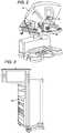
- FIG. 2is a perspective view of the Surgeon's Console 16.
- the Surgeon's Console 16includes a left eye display 32 and a right eye display 34 for presenting the Surgeon 18 with a coordinated stereo view of the surgical site that enables depth perception.
- the Console 16further includes one or more input control devices 36, which in turn cause the Patient Side Cart 22 (shown in FIG. 1 ) to manipulate one or more tools.
- the input control devices 36can provide the same degrees of freedom as their associated tools 26 (shown in FIG. 1 ) so as to provide the Surgeon with telepresence, or the perception that the input control devices 36 are integral with the tools 26 so that the Surgeon has a strong sense of directly controlling the tools 26.
- position, force, and tactile feedback sensorsmay be employed to transmit position, force, and tactile sensations from the tools 26 back to the Surgeon's hands through the input control devices 36.
- the Surgeon's Console 16is usually located in the same room as the patient so that the Surgeon may directly monitor the procedure, be physically present if necessary, and speak to an Assistant directly rather than over the telephone or other communication medium. However, the Surgeon can be located in a different room, a completely different building, or other remote location from the Patient allowing for remote surgical procedures.
- FIG. 3is a perspective view of the Electronics Cart 24.
- the Electronics Cart 24can be coupled with the endoscope 28 and can include a processor to process captured images for subsequent display, such as to a Surgeon on the Surgeon's Console, or on another suitable display located locally and/or remotely.
- the Electronics Cart 24can process the captured images so as to present the Surgeon with coordinated stereo images of the surgical site.
- Such coordinationcan include alignment between the opposing images and can include adjusting the stereo working distance of the stereoscopic endoscope.
- image processingcan include the use of previously determined camera calibration parameters so as to compensate for imaging errors of the image capture device, such as optical aberrations.
- FIG. 4diagrammatically illustrates a robotic surgery system 50 (such as MIRS system 10 of FIG. 1 ).
- a Surgeon's Console 52(such as Surgeon's Console 16 in FIG.1 ) can be used by a Surgeon to control a Patient Side Cart (Surgical Robot) 54 (such as Patent Side Cart 22 in FIG. 1 ) during a minimally invasive procedure.
- the Patient Side Cart 54can use an imaging device, such as a stereoscopic endoscope, to capture images of the procedure site and output the captured images to an Electronics Cart 56 (such as the Electronics Cart 24 in FIG. 1 ).
- the Electronics Cart 56can process the captured images in a variety of ways prior to any subsequent display.
- the Electronics Cart 56can overlay the captured images with a virtual control interface prior to displaying the combined images to the Surgeon via the Surgeon's Console 52.
- the Patient Side Cart 54can output the captured images for processing outside the Electronics Cart 56.
- the Patient Side Cart 54can output the captured images to a processor 58, which can be used to process the captured images.
- the imagescan also be processed by a combination the Electronics Cart 56 and the processor 58, which can be coupled together so as to process the captured images jointly, sequentially, and/or combinations thereof.
- One or more separate displays 60can also be coupled with the processor 58 and/or the Electronics Cart 56 for local and/or remote display of images, such as images of the procedure site, or other related images.
- FIGS. 5A and 5Bshow a Patient Side Cart 22 and a surgical tool 62, respectively.
- the surgical tool 62is an example of the surgical tools 26.
- the Patient Side Cart 22 shownprovides for the manipulation of three surgical tools 26 and an imaging device 28, such as a stereoscopic endoscope used for the capture of images of the site of the procedure. Manipulation is provided by robotic mechanisms having a number of robotic joints.
- the imaging device 28 and the surgical tools 26can be positioned and manipulated through incisions in the patient so that a kinematic remote center is maintained at the incision so as to minimize the size of the incision.
- Images of the surgical sitecan include images of the distal ends of the surgical tools 26 when they are positioned within the field-of-view of the imaging device 28.
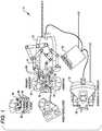
- FIG. 6Ashows a surgical tool 70 that includes a proximal chassis 72, an instrument shaft 74, and a distal end effector 76 having a jaw 78 that can be articulated to grip a patient tissue.
- the proximal chassisincludes an input coupler that is configured to interface with and be driven by an output coupler of the Patient Side Cart 22.
- the input coupleris drivingly coupled with an input link of a spring assembly 80.
- the spring assembly 80is mounted to a frame 82 of the proximal chassis 72 and includes an output link that is drivingly coupled with a drive shaft that is disposed within the instrument shaft 74.
- the drive shaftis drivingly coupled with the jaw 78.
- FIG. 6Bprovides a close-up view of the jaw 78 of the end effector 76.
- FIG. 7is an exploded perspective view of the end effector 76 of FIG. 6A , illustrating a clamping mechanism used to convert rotary motion of a drive shaft 84 into articulation of opposing clamping jaws of the end effector 76.
- the end effectorincludes an upper jaw 86, a lower jaw 88, a frame 90, a pin 92 for pivotally mounting the upper jaw 86 and the lower jaw 88 to the frame 90, and a lead screw mechanism 94 that is drivingly coupled with the drive shaft 84.
- the lead screw mechanism 94includes a lead screw 96 and a mating translating nut 98 that is advanced and retracted along a slot 100 in the frame 90 via rotation of the lead screw 96.
- the translating nut 98includes oppositely extending protrusions that interface with a slot 102 in the upper jaw 86 and with a slot 104 in the lower jaw 88, thereby causing articulation of the upper jaw 86 and the lower jaw 88 about the pin 92 when the translating nut 98 is advanced or retracted along the slot 100.
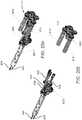
- FIG. 8A and FIG. 8Billustrate the operation of a clamping mechanism similar to the clamping mechanism of FIG. 7 .
- Rotating the drive shaft 84 in the direction showncauses a translating nut 98 to advance distally toward the pivot pin 92 by which the lower jaw 88 and the upper jaw 86 are pivotally mounted to the frame 90 of an end effector.
- a protrusion of the translating nut 98engages the slot 102 in the upper jaw 86.
- Distal advancement of the translating nut 98 toward the pivot pin 92causes the upper jaw to rotate in the direction shown, and causes the lower jaw 88 to rotate in the opposite direction, thereby opening the jaw.
- proximal advancement of the translating nut 98 away from the pivot pin 92cause the jaw to close. Accordingly, the jaw can be articulated to grip a patient tissue.
- the lead screw type clamping mechanisms shown in FIG 7, FIG. 8A, and FIG. 8Bprovide a substantial mechanical advantage, which converts a relatively low torque transmitted by the drive shaft into a relatively high clamping force. To avoid subjecting tissue to an excessive clamping force via a mechanism having such a substantial mechanical advantage, the torque transmitted into the clamping mechanism by the drive shaft can be controlled.
- the drive shaft 84can be used to actuate any suitable end effector mechanism.
- the drive shaft 84can be used to actuate mechanisms such as a tissue stapling mechanism, a tissue cutting mechanism, and in general any suitable end effector mechanism that can be actuated by a rotational input.
- FIG. 9provides an appropriate starting point for discussing decoupling of instrument shaft roll and end effector actuation in a surgical instrument.
- FIG. 9shows an end effector 110 that includes an articulated jaw 112 operable to grip an item (e.g ., patient tissue, a suture needle, etc.).
- the end effector 110includes an actuation mechanism for actuating a mechanism of the end effector 110, such as the articulated jaw 112.
- the actuation mechanismis drivingly coupled with a drive shaft 114.
- the end effector 110is supported at a distal end of an instrument shaft 116.
- the instrument shaft 116is rotatable through a range of rotation relative to a proximal chassis base that supports the instrument shaft 116.
- the drive shaft 114is rotatable through a range of rotation relative to the proximal chassis base.
- the portion of the range of rotation of the drive shaft 114 relative to the proximal chassis base that can be used to actuate the end effector jaw 112is reduced by the range of rotation of the instrument shaft 116 relative to the proximal chassis base.
- the net range of rotation of the drive shaft 114 relative to the end effector 110is equal to eight revolutions.
- FIG. 10schematically illustrates the use of a differential 118 for combining a first input motion 120 with an instrument shaft rotation 122 to generate an output motion 124 for driving an end effector actuation mechanism.
- the differential 118can be configured to counteract the above-discussed impact of instrument shaft rotation on producing a difference between the amount of rotation of the drive shaft 114 relative to the proximal chassis base and the corresponding amount of rotation of the drive shaft 114 relative to the end effector actuation mechanism.
- the differential 118can be configured to combine a first input motion 120 of two clockwise revolutions relative to the proximal chassis base with an instrument shaft motion 122 of one clockwise revolution relative to the proximal chassis base to produce an output motion 124 of three clockwise revolutions relative to the proximal chassis base, which effectively provides an output motion of two clockwise revolutions relative to the end effector.
- Such a differential configurationalso serves to counteract the above-discussed impact of instrument shaft rotation when the drive shaft 114 and the instrument shaft 116 are rotated in opposite directions.
- two clockwise revolutions of the first input motion 120 relative to the proximal chassis basecombine with one counterclockwise revolution of the instrument shaft 122 relative to the base to produce an output motion 124 of one clockwise revolution relative to the base, which effectively produces an output motion of two clockwise revolutions of the output motion relative to the end effector.
- the differentialcan also be configured to counteract the impact of instrument shaft rotation to any suitable degree.
- the differentialcan be configured to under counteract, over counteract, and even magnify the impact of the above-discussed impact of instrument shaft rotation as suitable for achieving desired operational characteristics of the surgical instrument.
- the differentialcan be implemented in any suitable way.
- the differentialcan be implemented using cables and pulleys.
- the differentialcan be implemented using gearing, such as a planetary gear box assembly.
- FIG. 11Aillustrates a cable implemented differential 130 used to decouple instrument shaft roll and end effector actuation in a robotic surgical instrument, in accordance with many embodiments.
- the differential 130includes a roll pulley 132 that is rotationally coupled with rotation of an instrument shaft relative to a proximal chassis base, an end effector actuation pulley 134 that is rotationally coupled with an actuation source, and a lead-screw drive pulley 136 that is rotationally coupled with an end effector jaw actuation mechanism.
- a first cable 138that engages both the roll pulley 132 and the lead-screw drive pulley 136 provides for rotation of the lead-screw drive pulley 136 in response to rotation of the roll pulley 132.
- a second cable 140 that engages the end effector actuation pulley 134is coupled with a first pulley block 142 and a second pulley block 144.
- the first pulley block 142includes a first moving pulley 146.
- the second pulley block 144includes a second moving pulley 148.
- the first and second moving pulleys 146, 148engage the first cable 138.
- the first cable 138engages four fixed guide pulleys.
- These fixed guide pulleysinclude a first guide pulley 150, a second guide pulley 152, a third guide pulley 154, and a fourth guide pulley 156.
- FIG. 11Bis a side view of the cable implemented differential 130.
- the roll pulley 132is rotationally coupled with rotation of the instrument shaft through a helical gear 158.
- the roll pulley 132 and the helical gear 158rotate about an axis of rotation 160.
- the instrument shaftrotates about an axis of rotation that is oriented transverse to the helical gear axis of rotation 160.
- the helical gear 158 and a mating helical gear attached to rotate with the instrument shafttransfer rotation of the instrument shaft to rotation of the roll pulley 132.
- the four fixed guide pulleys 150, 152, 154, 156serve to constrain the location of the first cable 138 both horizontally and vertically.
- the first and third guide pulleys 150, 154are positioned below the second and fourth guide pulleys 152, 156 to provide vertical separation between overlapping portions of the first cable 138.
- the first and third guide pulleys 150, 154are also positioned horizontally to provide for a 180 degree engagement between the first moving pulley 146 and the first cable 138 throughout the range of travel of the first moving pulley 146.
- the second and fourth guide pulleys 152, 156are also positioned horizontally to provide for a 180 degree engagement between the second moving pulley 148 and the first cable 138 throughout the range of travel of the second moving pulley 148.
- the cable implemented differential 130combines the motion of the roll pulley 132 and the motion of the end effector actuation pulley 134 to produce motion of the lead-screw drive pulley 136.
- rotation of the roll pulley 132produces a corresponding rotation of the lead-screw drive pulley 136, thereby resulting in no net rotation of the lead-screw drive pulley 136 relative to the end effector jaw actuation mechanism.
- FIG. 12is a perspective view of a proximal chassis of a robotic surgical instrument having a cable implemented differential 170, in accordance with many embodiments.
- the cable implemented differential 170is configured similar to the cable implemented differential 130, but includes six fixed guide pulleys 172, 174, 176, 178, 180, 182 to constrain a first cable 184 horizontally and vertically.
- any suitable cable implemented differentialcan be used.
- the first cable 138is driven by the end effector actuation pulley 134 and the second cable 140 is driven by the roll pulley 132.
- FIG. 13is a perspective view of a proximal chassis 190 of a robotic surgical instrument that includes a gear implemented differential 192, in accordance with many embodiments.
- the gear implemented differential 192includes a planetary gear assembly having a sun gear, planet gears coupled to a carrier, and a ring gear.
- the carrieris rotationally coupled with an input coupler of the proximal chassis through an input shaft.
- the input shaftis aligned with the input coupler and is transverse to the instrument shaft.
- the sun gearis rotationally coupled with rotation of the instrument shaft 116 through helical gears 194, 196. Rotations of the carrier and the sun gear result in rotation of the ring gear.
- FIG. 14shows a plan view of the proximal chassis 190 and the gear implemented differential 192.
- FIG. 15shows a side view of the proximal chassis 190 and the gear implemented differential 192.
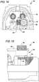
- FIG. 16 and FIG. 17are exploded views illustrating details of a gear implemented differential 210, in accordance with many embodiments.
- the gear implemented differential 210includes a planetary gear box assembly 212.
- FIG. 16shows the gear implemented differential 210 and attached input shaft and input coupler 214 displaced sideways from where they would be installed in a proximal chassis 216 of a robotic surgical instrument having an instrument shaft 116.
- An installed centerline 218 and a central axis 220 of the gear implemented differential 210illustrate the offset from the installed position.
- FIG. 17is an exploded perspective view of the gear implemented differential 210, the input shaft, and the input coupler 214.
- the differential 210includes a carrier 222 that is coupled with planet gears 224, a sun gear 226 that is rotationally driven by an input gear 228, a ring gear member 230 that has an internal ring gear and an external helical output gear 232.
- the carrier 222is rotationally coupled with and driven by an input shaft 234, which is rotationally coupled with and driven by an input coupler 214.
- the input coupler 214interfaces with and is rotationally driven by a corresponding output coupler of a robotic arm of a surgical robot when the proximal chassis 216 is mounted to the robotic arm.
- Rotation of the carrier 222results in rotation of centerlines of the planet gears 224 around the central axis 220.
- the input gear 228is rotationally coupled with rotation of the instrument shaft 116.
- the combined rotation of the sun gear 226 and the centerlines of planet gears 224 around the central axis 220results in corresponding rotation of the ring gear member 230 about the central axis 220.
- the ring gear member 230is drivingly coupled with an end effector actuation mechanism through the external helical output gear 232.
- the gear implemented differential 210includes a torsion spring 236 coupled between the carrier 222 and the proximal chassis 216.
- the torsion springreturns the carrier to a predetermined position following a disconnect between the carrier and an actuation source in the robotic arm, thereby returning the end effector actuation mechanism to a predetermined configuration.
- the gear implemented differential 210operates similar to the differential 118 discussed above. Additional gearing per known approaches can be used to account for directional and rotational speed differences between the instrument shaft 116 and the resulting output motion of the external helical output gear 232.
- the angular velocity of the ring gear member 230is a linear combination of the angular velocity of the sun gear 226 and the angular velocity of the carrier 222. Accordingly, in the gear implemented differential 210 (where the sun gear 226 is rotationally driven by rotation of the instrument shaft 116, where the carrier 222 is rotationally driven by the input coupler 214, and where the ring gear member 230 is rotationally coupled with an end effector actuation mechanism) rotation of the instrument shaft 116 results in a corresponding additional rotation of the ring gear member 230, thereby decoupling instrument shaft rotation from the actuation of the end effector actuation mechanism.
- the surgical assemblies disclosed hereincan be employed in any suitable application.
- the surgical assemblies disclosed hereincan be employed in other surgical instruments, manual or powered, hand-held or robotic, directly controlled or teleoperated, for open or minimally invasive (single or multi-port) procedures.
- An example of such instrumentsinclude those with distal components that receive torque actuating inputs (e.g ., for grip control functions, component orientation control functions, component position functions, etc .).
- Illustrative non-limiting examplesinclude teleoperated or hand-held instruments that include stapling, cutting, tissue fusing, imaging device orientation and position control, high force grasping, biopsy, and end effector and orientation control.
- FIG. 18illustrates acts of a method 250 of decoupling rotation of a surgical instrument shaft from rotation of a drive shaft drivingly coupled with a mechanism of an end effector supported by the surgical instrument shaft, in accordance with many embodiments.
- the method 250can practiced, for example, by using any suitable differential, such as any of the differential 118, the cable implemented differential 130, the cable implemented differential 170, and the gear implemented differential 192 as described above.
- the method 250includes generating a first input motion associated with a desired end effector configuration (act 252); rotating the surgical instrument shaft relative to a base, the surgical instrument shaft extending between a proximal end adjacent to the base and a distal end that supports the end effector (act 254); generating a second input motion in response to the rotation of the surgical instrument shaft relative to the base (act 256), combining the first and second input motions to generate an output motion (act 258), and rotating the drive shaft in response to the output motion (act 260).
- the first and second input motionsare combined such that no substantial rotation of the drive shaft relative to the surgical instrument occurs when the first input motion is zero.
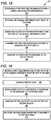
- FIG. 19illustrates acts that can be used to practice the method 250 by using a cable implemented differential, such as any of those described herein.
- the actsinclude moving a first cable in response to the rotation of the surgical instrument shaft relative to the base (act 262), moving a second cable (act 264), moving a first pulley and a second pulley in response to the movement of the second cable (act 266), engaging the first cable with each of the first and second pulleys (act 268), and rotating the drive shaft in response to movement of the first cable (act 270).
- the first cableis engaged with each of the first and second pulleys over an approximately 180 degree sector of the respective pulley.
- FIG. 20illustrates acts that can be used to practice the method 250 by using a cable implemented differential, such as any of those described herein.
- the actsinclude moving a first cable (act 272), moving a second cable in response to the rotation of the surgical instrument shaft relative to the base (act 274), moving a first pulley and a second pulley in response to the movement of the second cable (act 276), engaging the first cable with each of the first and second pulleys (act 278), and rotating the drive shaft in response to movement of the first cable (act 280).
- the first cableis engaged with each of the first and second pulleys over an approximately 180 degree sector of the respective pulley.
- FIG. 21illustrates acts that can be used to practice the method 250 by using a gear implemented differential, such as any of those described herein.
- the actsinclude rotating a first input link of a differential gear assembly in response to the first input motion (act 282), rotating a second input link of the differential gear assembly in response to the second input motion (act 284), and rotating the drive shaft in response to rotation of an output link of the differential gear assembly (act 286).
- the methods disclosed hereincan be employed in any suitable application.
- the methods disclosed hereincan be employed in surgical instruments, manual or powered, hand-held or robotic, directly controlled or teleoperated, for open or minimally invasive (single or multi-port) procedures.
- An example of such instrumentsinclude those with distal components that receive torque actuating inputs (e.g., for grip control functions, component orientation control functions, component position functions, etc .).
- Illustrative non-limiting examplesinclude teleoperated or hand-held instruments that include stapling, cutting, tissue fusing, imaging device orientation and position control, high force grasping, biopsy, and end effector and orientation control.
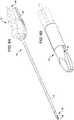
- FIG. 22diagrammatically illustrates a robotic assembly 370 having two offset drive shafts within a rotatable main shaft.
- the robotic assembly 370includes an end effector 372 that is coupled with the distal end of a rotatable main shaft 374, and an actuation assembly 376 coupled with both the main shaft 374 and the end effector 372.
- the end effector 372includes an end effector base, a first actuation mechanism 378, a second actuation mechanism 380, and a control cable mechanism(s) 382.
- the end effector baseis pivotally coupled to the rotatable main shaft 374.
- the first actuation mechanism 378 and the second actuation mechanism 380are shaft driven and can be used to actuate and/or articulate a variety of end effector features and/or devices, for example, a clamping feature, a movable cutting feature, a cutting and stapling device, or another suitable end effector feature and/or device that can be actuated and/or articulated with a shaft driven mechanism.
- the control cable mechanism(s) 382can also be used to actuate and/or articulate a variety of end effector features and/or devices, particularly those where a fast response is desired, for example, a grasping feature, a main shaft to end effector base wrist that is used to articulate the end effector base relative to the main shaft, or another suitable feature and/or device that can be actuated and/or articulated via one or more control cables.
- the end effector baseis coupled with the rotatable main shaft 374 so that a rotation of the main shaft 374 about a main shaft rotation axis produces a corresponding rotation of the end effector base.
- the ability to independently rotate the main shaft 374provides increased end effector maneuverability relative to a non rotating main shaft, which may be beneficial during certain surgical procedures, for example, during certain minimally invasive surgical procedures.
- the end effector basecan also be coupled with the rotatable main shaft 374 with a suitable wrist mechanism 384 that provides additional end effector maneuverability.
- a first drive shaft 386is mounted for rotation about a first drive shaft rotational axis that is offset from the main shaft rotation axis.
- the first drive shaft 386is operatively coupled with the first actuation mechanism 378.
- a second drive shaft 388is mounted for rotation about a second drive shaft rotational axis that is offset from the main shaft rotation axis.
- the second drive shaft 388is operatively coupled with the second actuation mechanism 380.
- the actuation assembly 376is coupled with the rotatable main shaft 374, the first drive shaft 386, the second drive shaft 388, and the control cable mechanism(s) 382.
- the rotatable main shaft 374is mounted for rotation relative to a base of the actuation assembly 376.
- the actuation assembly 376is operable to produce rotation of the rotatable main shaft 374 relative to the base.
- the actuation assembly 376is also operable to generate any combination of rotation of the rotatable main shaft 374 relative to the base, rotation of the first drive shaft 386 relative to the rotatable main shaft 374, and rotation of the second drive shaft 388 relative to the rotatable main shaft 374.
- the first actuation mechanism 378 and/or the second actuation mechanism 380can be actuated independently and/or simultaneously with rotation of the rotatable main shaft 374.
- the actuation assembly 376is configured to provide the above described functionality in which the first drive shaft 386 and the second drive shaft 388 can be independently rotated relative to the rotatable main shaft 374, even during rotation of the rotatable main shaft 374 relative to the base.
- the actuation assembly 376includes a main shaft motor 390 coupled with a main shaft encoder 392 and a main shaft interface 394, a first motor 396 coupled with a first encoder 398 and a first interface 400, a second motor 402 coupled with a second encoder 404 and a second interface 406, and a control cable motor(s) 408 coupled with a control cable encoder(s) 410 and a control cable intcrfacc(s) 412.
- the main shaft interface 394is coupled with the rotatable main shaft 374 so as to transfer rotational motion from the main shaft motor 390 to the rotatable main shaft 374.
- the main shaft motor 390can be fixedly coupled with the base so that the transferred rotational motion results in rotation of the rotatable main shaft 374 relative to the base.
- the main shaft encoder 392measures the orientation of the main shaft motor 390, the main shaft interface 394, and/or the rotatable main shaft 374 and can be coupled with a controller (not shown in FIG. 22 ) so as to provide the controller with the measured orientation.
- the first interface 400is coupled with the first drive shaft 386 so as to be operable to transfer rotational motion from the first motor 396 to the first drive shaft 386 during any orientation and/or rotational motion of the rotatable main shaft 374.
- the first encoder 398measures the orientation of the first motor 396, the first interface 400, and/or the first drive shaft 386 and can be coupled with the controller so as to provide the controller with the measured orientation.
- the second interface 406is coupled with the second drive shaft 388 so as to be operable to transfer rotational motion from the second motor 402 to the second drive shaft 388 during any orientation and/or rotational motion of the rotatable main shaft 374.
- the second encoder 404measures the orientation of the second motor 402, the second interface 406, and/or the second drive shaft 388 and can be coupled with the controller so as to provide the controller with the measured orientation.
- the control cable interface(s) 412is coupled with control cable(s) 414 that are operatively coupled with the control cable mechanism(s) 382.
- the control cable(s) 414can be routed so as to tolerate a range of rotational orientations of the rotatable main shaft 374, for example, by being routed in the vicinity of the main shaft rotational axis to minimize changes in control cable length due to rotation of the rotatable main shaft 374, and by being configured to tolerate any twisting of control cable(s) and/or twisting between control cables that may result for some rotational orientations of the main shaft 374 ( e.g ., by having a construction that tolerates cable-to-cable rubbing).
- the control cable encoder(s) 410measures the orientation of the control cable motor(s) 408 and/or the control cable interface(s) 412 and can be coupled with the controller so as to provide the controller with the measured orientation(s).
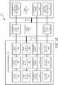
- FIG. 23is a simplified block diagram illustrating the integration of components of the robotic assembly 370 with a controller 416, in accordance with many embodiments.
- the controller 416includes at least one processor 418, which communicates with a number of peripheral devices via a bus subsystem 420. These peripheral devices typically include a storage subsystem 422.
- the storage subsystem 422maintains the basic programming and data constructs that provide the functionality of the controller 416.
- Software modules for implementing the robotic assembly functionality discussed aboveare typically stored in the storage subsystem 422.
- the storage subsystem 422typically includes a memory subsystem 424 and a file storage subsystem 426.
- the memory subsystem 424typically includes a number of memories including a main random access memory (RAM) 428 for storage of instructions and data during program execution and a read only memory (ROM) 430, in which fixed instructions are stored.
- RAMmain random access memory
- ROMread only memory
- the file storage subsystem 426provides persistent (non-volatile) storage for program and data files, and can include a hard drive, a disk drive, or other non-volatile memory such as a flash memory.
- An input devicefor example a disk drive, can be used to input the software modules discussed above. Alternatively, other known structures may alternatively be used to input the software modules, for example, a USB port.
- bus subsystemis used generically so as to include any mechanism for letting the various components and subsystems communicate with each other as intended.
- the bus subsystem 420is shown schematically as a single bus, but a typical system has a number of buses such as a local bus and one or more expansion buses (e.g., ADB, SCSI, ISA, EISA, MCA, NuBus, or PCI), as well as serial and parallel ports.
- the controller 416controls components of the robotic assembly 370 in response to assorted received signals, including signals from the input control device(s) 36 (shown in FIG. 2 ), as well as from the main shaft encoder 392, the first encoder 398, the second encoder 404, and the control cable encoder(s) 410.
- the components controlledinclude the main shaft motor 390, the first motor 396, the second motor 402, and the control cable motor(s) 408. Additional components (not shown), such as digital/analog converters can be used to interface components with the controller 416.
- FIG. 24is a simplified block diagram illustrating the integration of a robotic surgery tool 432 within a robotic surgery system, in accordance with many embodiments.
- the tool 432includes a proximal tool chassis 434 configured to be releasably mountable on a manipulator 436 having a tool interface configured to interface with the proximal tool chassis 434.
- the tool 432further includes an elongate main shaft 374 that is mounted to rotate relative to the proximal tool chassis 434 when rotated by a main shaft motor, as discussed above.
- An end effector 440is coupled with a distal end of the main shaft 374 so as to rotate along with the main shaft.
- a main control system 442is operatively coupled with the manipulator 436.
- An auxiliary control system 444can also be operatively coupled with the manipulator 436.
- the combination of the main control system 442 and the auxiliary control system 444can be used to control all possible articulations of the tool 432 via the manipulator 436.
- the auxiliary control system 444can control the drive motors for first drive shaft rotation and second drive shaft rotation.
- the main control system 442can control a drive motor for main shaft rotation and one or more control cable drive motors.
- Such an auxiliary controllercan be used to supplement existing robotic surgery system configurations so as to allow the use of the presently disclosed robotic tools having one or more offset drive shafts routed within an independently rotating main shaft.
- FIG. 25diagrammatically illustrates a surgical assembly 500, in accordance with the invention, in which drive motors used to actuate end effector rotary mechanisms are coupled with a main shaft/end effector assembly so as to avoid unintentional rotation of the main shaft/end effector assembly during actuation of the end effector rotary mechanisms.
- the surgical assembly 500includes a main shaft/end effector assembly 502 that is rotationally mounted to a base ( e.g ., manipulator 436 as illustrated in FIG.
- a main shaft drive 504that rotationally drives the main shaft/end effector assembly 502 relative to the base
- a counteracting actuation assembly 506that is rotationally coupled with the main shaft/end effector assembly 502 so as to provide actuation torques to the end effector rotary mechanisms and a counteracting torque 507 to the main shaft/end effector assembly 502.
- the main shaft/end effector assembly 502includes a main shaft 508 that is rotationally mounted to the base and rotationally driven by the main shaft drive 504, and an end effector 510 that is supported by the main shaft 508.
- the end effector 510includes a first rotary mechanism 512 and a second rotary mechanism 514.
- the first and second rotary mechanisms 512, 514can be used to articulate end effector components, for example, a clamping jaw, a stapling device, a cutting device, and the like.
- first and second rotary mechanisms 512, 514are part of the end effector 510, which is supported by the main shaft 508 of the main shaft/end effector assembly 502, when actuation torques are transmitted to the first and second rotary mechanisms 512, 514 from the external source some or all of the transmitted actuation torque may be reacted by the main shaft 508.
- the actuation torque reacted by the main shaft/end effector assembly 502is also reacted by the main shaft drive 504.
- the main shaft drive 504may be back-drivable via a torque of sufficient magnitude reacted by the main shaft/end effector assembly 502.
- the main shaft drive 504may have a back-driving torque threshold such that the main shaft/end effector assembly 502 back drives the main shaft drive when the main shaft/end effector assembly 502 is subject to a net torque (including any torque necessary to overcome friction induced restraint) over the back-driving torque threshold and does not back drive the main shaft drive when the main shaft/end effector assembly 502 is subject to a net torque under the back-driving torque threshold.
- the counteracting actuation assembly 506is the external source that generates the actuation torques that are transmitted to the first and second rotary mechanisms 512, 514.
- the counteracting actuation assembly 506also generates a balancing torque that is transmitted to the main shaft 508 so as to prevent back driving of the main shaft drive 504.
- the counteracting actuation assembly 506includes a first drive motor 516, a second drive motor 518, a first transmission 520, a first rotational coupling 522, a second transmission 524, and a second rotational coupling 526.
- the first drive motor 516is rotationally coupled with the first rotary mechanism 512 and the main shaft 508 via the first transmission 520 and the first rotational coupling 522.
- the first drive motor 516is rotationally coupled with a first input link 528 of the first transmission and transmits a first input torque to the first input link 528.
- the first transmission 520provides a first gear ratio between the first input link 528 and a first output link 530 of the first transmission 520.
- the first output link 530is rotationally coupled with the first rotary mechanism 512.
- the first rotational coupling 522is connected between a first base link 532 of the first transmission 520 and the main shaft 508.
- the first rotational coupling 522provides a second gear ratio between the first base link 532 and the main shaft 508.
- the first base link 532is not rotationally grounded (e.g., not rotationally grounded to the base to which the main shaft 508 is rotationally mounted).
- the first gear ratio provided by the first transmission 520is sufficiently greater than one so that the first output link 530 transmits a torque that exceeds the first input torque. Because the first base link 532 of the first transmission 520 is not rotationally grounded, the difference between the torque transmitted by the first output link 530 and the first input torque is balanced by a torque in the opposite direction that is transmitted from the first base link 532 to the first rotational coupling 522. In many embodiments, the first gear ratio is significantly greater than one so that the torque transmitted by the first output link 530 and the torque in the opposite direction that is transmitted from the first base link 532 to the first rotational coupling 522 have roughly equivalent magnitudes.
- the torque transmitted by the first output link 530is 9 times the first input torque.
- the torque in the opposite direction transmitted by the first base link 532 to the first rotational coupling 522has a magnitude that is 8 times the magnitude of the first input torque.
- the second gear ratio provided by the first rotational coupling 522is selected so that the torque transmitted to the main shaft 508 by the first rotational coupling 522 sufficiently balances the torque transmitted into the main shaft/end effector assembly 502 by the first output link 530 so as to inhibit rotational driving of the main shaft drive 504 by the main shaft/end effector assembly 502.
- the second gear ratiocan be selected from a range of gear ratios and still result in the inhibition of rotational driving of the main shaft drive by the main shaft/end effector assembly 502.
- the second gear ratiois selected such that the torque transmitted to the main shaft by the first rotation coupling substantially balances the torque transmitted into the main shaft/end effector assembly 502 by the first output link 530.
- the first output link 530 of the first transmission 520need not be directly rotationally coupled to the main shaft/end effector assembly 502, but instead can be coupled in a way so as to provide a non-unity gear ratio between the first output link 530 and the main shaft/end effector assembly 502. Where such a non-unity gear ratio exists, the second gear ratio provided by the first rotational coupling 522 can be configured to account for the additional non-unity gear ratio.
- the second drive motor 518is rotationally coupled with the second rotary mechanism 514 and the main shaft 508 via the second transmission 524 and the second rotational coupling 526.
- the second drive motor 518is rotationally coupled with a second input link 534 of the second transmission and transmits a second input torque to the second input link 534.
- the second transmission 524provides a third gear ratio between the second input link 534 and a second output link 536 of the second transmission 524.
- the second output link 536is rotationally coupled with the second rotary mechanism 514.
- the second rotational coupling 526is connected between a second base link 538 of the second transmission 524 and the main shaft 508.
- the second rotational coupling 526provides a fourth gear ratio between the second base link 538 and the main shaft 508.
- the second base link 538is not rotationally grounded ( e.g ., not rotationally grounded to the base to which the main shaft 508 is rotationally mounted).
- the third gear ratio provided by the second transmission 524is sufficiently greater than one so that the second output link 536 transmits a torque that exceeds the second input torque. Because the second base link 538 of the second transmission 524 is not rotationally grounded, the difference between the torque transmitted by the second output link 536 and the second input torque is balanced by a torque in the opposite direction that is transmitted from the second base link 538 to the second rotational coupling 526. In many embodiments, the third gear ratio is significantly greater than one so that the torque transmitted by the second output link 536 and the torque in the opposite direction that is transmitted from the second base link 538 to the second rotational coupling 526 have roughly equivalent magnitudes.
- the torque transmitted by the second output link 536is 9 times the second input torque.
- the torque in the opposite direction transmitted by the second base link 538 to the second rotational coupling 526has a magnitude that is 8 times the magnitude of the second input torque.
- the fourth gear ratio provided by the second rotational coupling 526is selected so that the torque transmitted to the main shaft 508 by the second rotational coupling 526 sufficiently balances the torque transmitted into the main shaft/end effector assembly 502 by the second output link 536 so as to inhibit rotational driving of the main shaft drive 504 by the main shaft/end effector assembly 502.
- the fourth gear ratiocan be selected from a range of gear ratios and still result in the inhibition of rotational driving of the main shaft drive by the main shaft/end effector assembly 502.
- the fourth gear ratiois selected such that the torque transmitted to the main shaft by the second rotation coupling substantially balances the torque transmitted into the main shaft/end effector assembly 502 by the second output link 536.
- the second output link 536 of the second transmission 524need not be directly rotationally coupled to the main shaft/end effector assembly 502, but instead can be coupled in a way so as to provide a non-unity gear ratio between the second output link 536 and the main shaft/end effector assembly 502. Where such a non-unity gear ratio exists, the fourth gear ratio provided by the second rotational coupling 524 can be configured to account for the additional non-unity gear ratio.
- the main shaft/end effector assembly 502includes a first gear assembly 540 that provides a gear ratio between the first output link 530 and a first drive shaft 542 that is rotationally coupled with the first rotary mechanism 512 and a second gear assembly 544 that provides a gear ratio between the second output link 536 and a second drive shaft 546 that is rotationally coupled with the second rotary mechanism 514.
- first gear assembly 540that provides a gear ratio between the first output link 530 and a first drive shaft 542 that is rotationally coupled with the first rotary mechanism 512
- a second gear assembly 544that provides a gear ratio between the second output link 536 and a second drive shaft 546 that is rotationally coupled with the second rotary mechanism 514.
- any torque differentials generated by non-unity gear ratios of the first and second gear assemblies 540, 544are reacted by the main shaft 508 as are the torques transmitted to the first and second rotary mechanisms 512, 514.
- the gear ratios of the first and second gear assemblies 540, 544do not impact the configuration (e.g., gear ratios) of the counteracting actuation assembly 506 with respect to the magnitude of the counteracting torque 507 used to counteract the actuation torques transmitted to the main shaft/end effector assembly 502 by the first and second output links 530, 536.
- the torque(s) transmitted into the main shaft/end effector assembly 502 via the first and second output links 530, 536can exceed the back-driving torque threshold of the main shaft drive 504 while counteracting torque transmitted to the main shaft 508 via the counteracting actuation assembly 506 inhibits rotational driving of the main shaft drive 504.
- the counteracting actuation assembly 506is configured such that the magnitude of the counteracting torque differs from the magnitude of the torque(s) transmitted into the main shaft/end effector assembly 502 by the first and second output links 530, 536 by a net torque magnitude that is less than the back-driving torque threshold for the main shaft drive 504 even when the torque transmitted into the main shaft/end effector assembly 502 by the first and second output links 530, 536 exceeds the back-driving torque threshold.
- the net torque magnitudeis less than 50 percent of the back-driving torque threshold, even when the torque transmitted into the main shaft/end effector assembly 502 by the first and second output links 530, 536 exceeds the back-driving torque threshold.
- the net torque magnitudeis less than 25 percent of the back-driving torque threshold, even when the torque transmitted into the main shaft/end effector assembly 502 by the first and second output links 530, 536 exceeds the back-driving torque threshold. More preferably still, the net torque magnitude is less than 10 percent of the back-driving torque threshold, even when the torque transmitted into the main shaft/end effector assembly 502 by the first and second output links 530, 536 exceeds the back-driving torque threshold. And ideally, the net torque magnitude is less than 2 percent of the back-driving torque threshold, even when the torque transmitted into the main shaft/end effector assembly 502 by the first and second output links 530, 536 exceeds the back-driving torque threshold.
- friction in the surgical assembly 500 that acts in restraint to rotation of the main shaft/end effector assembly 502 relative to the basemay be sufficient to prevent rotation of the main shaft/end effector assembly 502 where the net torque magnitude is less than 2 percent of the back-driving torque threshold.
- the first rotational coupling 522 and the second rotational coupling 536can share one or more common components that are rotationally coupled with the main shaft 508.
- a common drive shaftcan be rotationally coupled with the main shaft 508 to transmit counteracting torque from one or both of the base links 532, 538 to the main shaft 508.
- FIG. 26illustrates an exemplary planetary gear set 550.
- the planetary gear set 550includes a sun gear 552 that is attached to an input link 554, a ring gear 556, four planet gears 558 distributed around the sun gear 552 and rotationally coupling the sun gear 552 to the ring gear 556, and a carrier 560 that is rotationally coupled with and supports each of the planet gears 558.
- planetary gear boxesprovide suitable features that can be used, in any possible combination, as the first and second input links 528, 534, the first and second output links 530, 536, and the first and second base links 532, 538 of the first and second transmissions 520, 524.
- a sun gearcan correspond to any one of the first and second input links, the first and second output links, and the first and second base links.
- a carriercan correspond to any one of the first and second input links, the first and second output links, and the first and second base links.
- a ring gearcan correspond to any one of the first and second input links, the first and second output links, and the first and second base links.
- a sun gearcan correspond to the first/second input link
- a carriercan correspond to the first/second output link
- a ring gearcan correspond to the first/second base link.
- a sun gearcan correspond to the first/second output link
- a carriercan correspond to the first/second input link
- a ring gearcan correspond to the first/second base link.
- a carrier or a sun gearcan correspond to the first/second base link.
- FIG. 27a , through FIG. 29cillustrate an embodiment of a minimally invasive robotic surgical instrument assembly 600 in accordance with the surgical assembly 500 of FIG. 9 .
- the instrument assembly 600includes an actuation assembly 602 disposed at a proximal end of the instrument assembly.
- a main shaft 604is rotationally mounted to the actuation assembly 602.
- a first drive shaft 606 and a second drive shaft 608are mounted for rotation within the main shaft 604, and transmit torque to a first rotary mechanism and a second rotary mechanism, respectively, of an end effector (not shown) supported at a distal end of the instrument assembly.
- FIG. 11ais a perspective exterior view of the actuation assembly.
- FIG. 11bis an exploded perspective view of the instrument assembly 600 that shows a motor pack 610 decoupled from drive couplings 612 through which the first and second drive motors are rotationally coupled with the main shaft 604 and the first and second drive shafts 606, 608.
- FIG. 28ais a perspective view of internal components of the instrument assembly 600.
- FIG. 28bis an exploded perspective view illustrating the internal components of FIG. 28a in a decoupled state corresponding to FIG. 27b .
- FIG. 29ais a perspective view of the internal components of the instrument assembly 600 with a second drive motor, a second planetary gear transmission, and a second coupling shaft removed so as to not obscure the illustration of the remaining components.
- FIG. 29bis an end view of the internal components of FIG. 29a .
- FIG. 29cillustrates cross section A-A of FIG. 29b .
- the instrument assembly 600includes a first drive motor 614, a first planetary transmission 616, a second drive motor 618, a second planetary transmission 620, a first coupling shaft 622, a second coupling shaft 624, and a common feedback shaft 626. Because the first and second planetary gear transmissions 616, 618 are rotationally grounded to the main shaft 604, the first and second planetary gear transmissions 616, 618 rotate relative to the first and second drive motors 614, 618, respectively, in response to rotation of the main shaft 604.
- the first coupling shaft 622forms part of a torque path between the carrier of the first planetary transmission 616 and the first drive shaft 606.
- the first drive motor 614transmits a first input torque to a sun gear of the first planetary transmission 616.
- a carrier of the first planetary transmission 616is rotationally coupled with the first coupling shaft 622 via intermeshing pinion gears.
- the first coupling shaft 622is rotationally coupled with the first drive shaft 606 via a pair of pinion gears and a ring gear as illustrated in FIG. 29a and FIG. 29c as well as described in U.S. Provisional Application No.
- the second coupling shaft 624forms part of a torque path between the carrier of the second planetary transmission 620 and the second drive shaft 608.
- the second drive motor 618transmits a second input torque to a sun gear of the second planetary transmission 620.
- a carrier of the second planetary transmission 620is rotationally coupled with the second coupling shaft 624 via intermeshing pinion gears.
- the second coupling shaft 624is rotationally coupled with the second drive shaft 608 via a pair of pinion gears and a ring gear as described in U.S. Provisional Application No.
- the common feedback shaft 626forms part of a torque path between the base link of the first planetary transmission 616 and the main shaft 604, as well as part of a torque path between the base link of the second planetary transmission 620 and the main shaft.
- the base link for the first planetary transmission 616is rotationally coupled with the common feedback shaft 626 via a pair of pinion gears, one of which forms part of the base link of the first planetary transmission 616.
- the base link of the second planetary transmission 620is rotationally coupled with the common feedback shaft 626 via a pair of pinion gears, one of which forms part of the base link of the second planetary transmission 620.
- the common feedback shaft 626is rotationally coupled with the main shaft 604 via a pair of pinion gears, one of which is directly rotationally coupled with the main shaft.
- the main shaft 604is rotationally coupled with a main drive motor (not shown) via a pair of helical gears 628, 630.
- the common feedback shaft 626 and the base links of the first and second transmissionsare also not rotating due to being rotationally coupled with the main shaft. Because the base links of the first and second planetary transmissions are not rotationally grounded to the base of the actuation assembly, the base links are free to rotationally deflect as required to transmit counteracting torque to the main shaft in response to input torques from the drive motors, and the base links are free to rotate as dictated by the rotation of the common drive shaft as dictated by any rotation of the main shaft by the main drive motor.
- the instrument assembly 600provides numerous advantages relative to alternate approaches that were evaluated to prevent undesirable main shaft rotation due to the transmission of actuation torque to rotary mechanisms of an end effector.
- the instrument assembly 600provides for the transmission of high levels of torque to one or both of the first and second rotary mechanisms of an end effector that is supported by an independently rotatable main shaft while at the same time providing for the transmission of counteracting torque to the main shaft, which can thereby result in substantially no net torque being applied to the main shaft that might back drive a main drive motor used to rotate the main shaft.
- the transmission of the counteracting torqueis accomplished passively, thereby avoiding the use of components that would be necessary with an active approach.
- the instrument assembly 600provides continuously linear performance in both rotational directions with no possibility for sudden release of energy.
- the instrument assembly 600is compatible with realistic packing solutions considering the relatively large size of the motors and the gearboxes relative to the size of the main shaft.
- the instrument assembly 600also requires no additional power to be applied relative to comparable instrument assemblies.
- the instrument assembly 600also exhibits substantial invariance to friction, wear, backlash, manufacturing precision, and the stiffness of components used in the mechanism. Because the gearing creates a kinematically closed system between the transmissions and the main shaft, any backlash is taken up in that closed system and thus no net torque above the mechanism's calculated residual torque is ever applied to the main shaft/end effector assembly. And all of the foregoing advantages are provided in an instrument assembly that provides for free rotation of the main shaft by the main drive motor during the transmission of torque to one or both of the first and second rotary mechanisms of the end effector.
- the alternate approaches evaluatedfailed to provide one or more of the foregoing advantages.
- the alternate approaches evaluatedincluded unidirectional spur gears, non-back drivable worm gear, friction brake, main shaft rotational lock, extra power applied via the main drive motor, active compensation of main shaft rotation via the main drive motor, using an auxiliary motor to compensate for the exerted torque, and mounting the motors and gear boxes to the main shaft.
- Self locking gear conceptsin particular, suffer from a problem wherein a change in the direction of rotation while under load can cause a sudden and rapid release of mechanical energy as the gear set goes from locked to unlocked.
- a brakehas a similar defect in that release of the brake can suddenly release energy.
- FIG. 30provides reference identifications for the following discussion regarding exemplary gear ratios that can be used in the surgical assembly 500 discussed above. Because the counteracting actuation assembly 506 uses a similar configuration for coupling the first and second drive motors 516, 518 with the main shaft/end effector assembly 502, the following discussion with be presented with respect to coupling the first drive motor 516 with the main shaft/end effector assembly 502 with the understanding that the discussion is also applicable with respect to coupling the second drive motor 518 with the main shaft/end effector assembly 502.
- TcTm ⁇ P ⁇ N 1 B / N 1 A ⁇ N 1 D / N 1 C
- Tr⁇ Tm ⁇ P ⁇ 1 ⁇ N 3 B / N 3 A ⁇ N 3 D / N 3 C
- the surgical assembly 500 and the instrument assembly 600can be implemented to substantially decouple the position of the end effector drive shafts from the position of the main shaft.
- the configuration of the surgical assembly 500can be selected such that when the first and second input links 528, 534 are not rotating ( i.e., the first and second drive motors 516, 518 are not rotating), a rotation of the main shaft 508 by the main shaft drive 504 will not cause a significant amount of rotation of the first and second drive shafts 542, 546 relative to the main shaft 508.
- the induced rotation of the first and second drive shafts 542, 546can be less than 10 percent of the rotation of the main shaft 508.
- the induced rotation of the first and second drive shafts 542, 546can be less than 5 percent of the rotation of the main shaft.
- This attributeis very beneficial.
- the first and second drive motors 516, 518have limited range of motion.
- the main shaft range of motionis not limited by the limited range of motion of the first and second drive motors 516, 518.
- such decouplingis beneficial relative to the operating characteristics of the end effector with regard to the first and second rotary mechanisms 512, 514 as such decoupling prevents substantial actuation of the first and second rotary mechanisms 512, 514 in response to mere rotation of the main shaft.
- the decouplinghelps to prevent inadvertent firing of staples due to rotation of the first and second rotary mechanisms 512, 514 induced by rotation of the main shaft 508.
- the amount of rotation of the first drive shaft 542 induced by a rotation of the main shaft 508can be calculated by Equation (3).
- parameters corresponding to the second drive shaft 546can be substituted for the parameters corresponding to the first drive shaft 542 in Equation (3) to calculate the amount of rotation of the second drive shaft 546 induced by a rotation of the main shaft 508.
- Ind rotMain rot ⁇ N 3 B N 3 A ⁇ N 3 D N 3 C ⁇ P ⁇ 1 P ⁇ N 1 A N 1 B ⁇ N 1 C N 1 D ⁇ 1 N 1 F N 1 E where:
- Tables 1 through 3list gearing parameters, resulting unit torque calculations, and levels of induced rotation for an end effector drive shaft for example embodiments.
- Table 1.First Example Embodiment Parameter Description Parameter Variable Parameter Value Motor 1 output torque Tm 1 Gear ratio for planetary gearbox P1 P 25 Number of teeth for gear 1A N 1 A 32 Number of teeth for gear 1B N 1 B 40 Number of teeth for gear 1C N 1 C 23 Number of teeth for gear 1D N 1 D 55 Number of teeth for gear 1E N 1 E 43 Number of teeth for gear 1F N 1 F 13 Resulting input drive torque T C 74.7 Number of teeth for gear 3A N 3 A 50 Number of teeth for gear 3B N 3 B 64 Number of teeth for gear 3C N 3 C 23 Number of teeth for gear 3D N 3 D 55 Resulting counteracting torque Tr -73.5 Percent torque imbalance (( Tc + Tr ) / Tc) / 100 1.7 percent Ref.
- FIG. 31illustrates a method 700 for preventing an actuation torque transmitted to an end effector from back driving a back-drivable main shaft during surgery, in accordance with many embodiments.
- the above surgical assembly 500 and the instrument assembly 600 described abovecan be used to practice the method 700. And one or more of the following acts can be omitted.
- a first input link of a first transmissionis rotated so that a first output link of the first transmission transmits a first output torque to a main shaft assembly that includes a main shaft and an end effector supported by the main shaft and transmits a first end effector torque to the end effector.
- the first transmissionprovides a first gear ratio between the first input link and the first output link.
- the first output torqueis greater than a back-driving torque threshold for a main shaft drive that is operable to rotationally drive the main shaft assembly.
- act 704torque is transmitted from a first base link of the first transmission to the main shaft via a first rotational coupling.
- the first rotational couplingprovides a second gear ratio between the first base link and the main shaft such that a first counteracting torque is applied to the main shaft that is opposite in direction to the first output torque.
- the first counteracting torqueinhibits rotational driving of the main shaft assembly by the first output torque.
- the main shaft drivemay have a back-driving torque threshold such that the main shaft back drives the main shaft drive when the main shaft assembly is subject to a net torque over the back-driving torque threshold and does not back drive the main shaft drive when the main shaft assembly is subject to a net torque under the back-driving torque threshold.
- the magnitude of the first counteracting torquediffers from the magnitude of the first output torque by a first net torque magnitude that is less than 50 percent of the back-driving torque threshold. More preferably, the first net torque magnitude is less than 25 percent of the back-driving torque threshold, even when the first output torque exceeds the back-driving torque threshold.
- the first net torque magnitudeis less than 10 percent of the back-driving torque threshold, even when the first end effector torque exceeds the back-driving torque threshold. And ideally, the first net torque magnitude is less than 2 percent of the back-driving torque threshold, even when the first end effector torque exceeds the back-driving torque threshold.
- a second input link of a second transmissionis rotated so that a second output link of the second transmission transmits a second output torque to the main shaft assembly and transmits a second end effector torque to the end effector.
- the second transmissionprovides a third gear ratio between the second input link and the second output link.
- the second output torque linkis greater than the back-driving torque threshold for the main shaft drive.
- torqueis transmitted from a second base link of the second transmission to the main shaft via a second rotational coupling.
- the second rotational couplingprovides a fourth gear ratio between the second base link and the main shaft such that a second counteracting torque is applied to the main shaft that is opposite in direction to the second output torque.
- the second counteracting torqueinhibits rotational driving of the main shaft assembly by the second output torque.
- the first and second rotational couplingscan share one or more common components.
- the first and second rotational couplingscan share a common drive shaft.
Landscapes
- Health & Medical Sciences (AREA)
- Life Sciences & Earth Sciences (AREA)
- Surgery (AREA)
- Engineering & Computer Science (AREA)
- Animal Behavior & Ethology (AREA)
- Veterinary Medicine (AREA)
- Biomedical Technology (AREA)
- Heart & Thoracic Surgery (AREA)
- Medical Informatics (AREA)
- Molecular Biology (AREA)
- Nuclear Medicine, Radiotherapy & Molecular Imaging (AREA)
- General Health & Medical Sciences (AREA)
- Public Health (AREA)
- Robotics (AREA)
- Ophthalmology & Optometry (AREA)
- Oral & Maxillofacial Surgery (AREA)
- Pathology (AREA)
- Manipulator (AREA)
- Surgical Instruments (AREA)
- Endoscopes (AREA)
- Transmission Devices (AREA)
Description
- Minimally invasive surgical techniques are aimed at reducing the amount of extraneous tissue that is damaged during diagnostic or surgical procedures, thereby reducing patient recovery time, discomfort, and deleterious side effects. As a consequence, the average length of a hospital stay for standard surgery may be shortened significantly using minimally invasive surgical techniques. Also, patient recovery times, patient discomfort, surgical side effects, and time away from work may also be reduced with minimally invasive surgery.
- A common form of minimally invasive surgery is endoscopy, and a common form of endoscopy is laparoscopy, which is minimally invasive inspection and surgery inside the abdominal cavity. In standard laparoscopic surgery, a patient's abdomen is insufflated with gas, and cannula sleeves are passed through small (approximately one-half inch or less) incisions to provide entry ports for laparoscopic instruments.
- Laparoscopic surgical instruments generally include an endoscope (e.g., laparoscope) for viewing the surgical field and tools for working at the surgical site. The working tools are typically similar to those used in conventional (open) surgery, except that the working end or end effector of each tool is separated from its handle by an extension tube (also known as,e.g., an instrument shaft or a main shaft). The end effector can include, for example, a clamp, grasper, scissor, stapler, cautery tool, linear cutter, or needle holder.
- To perform surgical procedures, the surgeon passes working tools through cannula sleeves to an internal surgical site and manipulates them from outside the abdomen. The surgeon views the procedure from a monitor that displays an image of the surgical site taken from the endoscope. Similar endoscopic techniques are employed in, for example, arthroscopy, retroperitoneoscopy, pelviscopy, nephroscopy, cystoscopy, cisternoscopy, sinoscopy, hysteroscopy, urethroscopy, and the like.
- Minimally invasive telesurgical robotic systems are being developed to increase a surgeon's dexterity when working on an internal surgical site, as well as to allow a surgeon to operate on a patient from a remote location (outside the sterile field). In a telesurgery system, the surgeon is often provided with an image of the surgical site at a control console. While viewing a three dimensional image of the surgical site on a suitable viewer or display, the surgeon performs the surgical procedures on the patient by manipulating master input or control devices of the control console. Each of the master input devices controls the motion of a servo-mechanically actuated/articulated surgical instrument. During the surgical procedure, the telesurgical system can provide mechanical actuation and control of a variety of surgical instruments or tools having end effectors that perform various functions for the surgeon, for example, holding or driving a needle, grasping a blood vessel, dissecting tissue, or the like, in response to manipulation of the master input devices.
- In many existing minimally invasive telesurgical robotic systems, manipulation of the surgical instruments is provided by a surgical robot having a number of robotic arms. Each of the robotic arms has a number of robotic joints and a mounting fixture for the attachment of a surgical instrument. Integrated in with at least one of the mounting fixtures are a number of drive couplers (e.g., rotary drive couplers) that drivingly interface with corresponding input couplers of a surgical instrument. The surgical instrument includes mechanisms that drivingly couple the input couplers with an associated motion of the surgical instrument (e.g., main shaft rotation, end effector pitch, end effector yaw, end effector jaw clamping, deployment of staples, tissue cutting, etc.). In many existing minimally invasive telesurgical robotic systems, each of the drive couplers of the surgical robot are cable driven so as to, for example, provide for precise control over the movement of the output couplers as is possible in cable driven actuation systems. By precisely controlling the movement of the output couplers, precise control over the associated motions of the surgical instrument can be achieved.
- A cable driven output coupler typically has a limited range of motion. Such a limited range of motion may not be detrimental where the output coupler is associated with a motion of the end effector that is not impacted by any other motion of the end effector. Such a limited range of motion may, however, be detrimental where the output coupler is associated with a motion of the end effector that is impacted by another motion of the end effector. For example, instrument shaft rotation may detrimentally couple with rotation of a drive shaft used to actuate an end effector mechanism (e.g., a clamping mechanism, a mechanism for the deployment of staples, a tissue cutting mechanism, etc.). Although compensating motions of the output couplers associated with the rotation of the instrument shaft and rotation of the drive shaft can be made, such compensating motions reduce the portion of the limited range of motion of the output couplers that can be used for their primary purpose.
- Thus, there is believed to be a need for surgical assemblies and related methods for decoupling related motions of a surgical instrument, particularly decoupling instrument shaft roll and end effector actuation in a surgical instrument.
- Manipulation and control of these effectors is also a particularly beneficial aspect of robotic surgical systems. For this reason, it is desirable to provide surgical tools that include mechanisms that provide three degrees of rotational movement of an end effector to mimic the natural action of a surgeon's wrist. Such mechanisms should be appropriately sized for use in a minimally invasive procedure and relatively simple in design to reduce possible points of failure. In addition, such mechanisms should provide an adequate range of motion to allow the end effector to be manipulated in a wide variety of positions.
- Non-robotic linear clamping, cutting and stapling devices have been employed in many different surgical procedures. For example, such a device can be used to resect a cancerous or anomalous tissue from a gastro-intestinal tract. Many known surgical devices, including known linear clamping, cutting and stapling devices, often have opposing jaws that are used to manipulate patient tissue.
- For known devices having opposing jaws, a significant amount of mechanical power must be delivered to the end effector to effectively, for example, clamp tissue, staple tissue, cut tissue, etc.. In most cases, the main shaft of the instrument must react at least a portion of mechanical forces and/or torques delivered to the end effector, whether via compression of the main shaft to react a tensile force or via torsion of the main shaft to react a torque delivered via a drive shaft disposed within the main shaft. If the main shaft or the mechanism used to rotationally position the main shaft, is not sufficiently rigid, the main shaft may move unexpectedly in response to the reacted force or torque.
- Document
EP1982567 A2 discloses a surgical instrument including a first elongated member and a second elongated member. The first elongated member and the second elongated member are operatively connected to each other and configured to rotate in opposite directions to substantially limit counter torque. - Document
WO2010009473 A1 discloses an ablation system with a mechanism to prevent built-up of torque between a main shaft and a drive shaft. - Thus, there is also believed to be a need for a surgical assembly that transmits high actuation torque to an end effector that does not experience unintended rotation of an independently rotatable main shaft used to support the end effector due to the transmitted actuation torque.
- The present invention is defined by appended
claim 1. Specific embodiments are set forth in the dependent claims. - Surgical assemblies and related methods are disclosed that provide for decoupling of instrument shaft roll and end effector actuation. In many embodiments, a differential is used to combine a motion associated with rotation of an instrument shaft with an input motion to generate an output motion to an actuation mechanism of an end effector supported by the distal end of the instrument shaft. The actuation mechanism articulates a portion of the end effector (e.g., a gripping jaw, a mechanism for the deployment of staples, a tissue cutting mechanism, etc.). The differential can be configured such that rotation of the instrument shaft results in substantially zero articulation of the end effector portion, thereby eliminating the possibility of any detrimental coupling between instrument shaft roll and end effector
- Thus, in one aspect, a surgical assembly is provided. The surgical assembly includes a base, an instrument shaft rotationally mounted to the base and extending between a distal end and a proximal end, an end effector supported at the distal end of the instrument shaft and including an actuation mechanism driven by a rotational motion, a drive shaft rotationally coupled with the actuation mechanism and configured to provide the rotational motion to the actuation mechanism, and a differential rotationally coupled to the drive shaft and receiving a first input motion and a second input motion. The differential is configured to combine the first and second input motions to generate the rotational motion that rotates the drive shaft. The first input motion is rotationally coupleable to an actuation source. And the second input motion is coupled to rotation of the instrument shaft relative to the base. In many embodiments, the end effector includes a jaw articulated by the actuation mechanism.
- The surgical assembly can be configured to substantially decouple actuation of the actuation mechanism from rotation of the instrument shaft. For example, the differential can be configured such that rotation of the instrument shaft relative to the base results in substantially zero rotation of the drive shaft relative to the instrument shaft when the first input motion is zero.
- The differential can be implemented by using cables and pulleys. For example, the differential can include a first cable drivingly coupling rotation of the drive shaft relative to the base to rotation of the instrument shaft relative to the base and a second cable drivingly coupled to the actuation source. In many embodiments, the second cable is coupled to first and second pulley blocks having first and second pulleys, respectively, the first cable being engaged by the first and second pulleys. As another example, the differential can include a first cable drivingly coupling rotation of the drive shaft relative to the base to the actuation source and a second cable drivingly coupled to rotation of the instrument shaft relative to the base. In many embodiments, the second cable is coupled to first and second pulley blocks having first and second pulleys, respectively, the first cable being engaged by the first and second pulleys.
- The differential can include a planetary gear box that includes a sun gear, planet gears coupled to a carrier, and a ring gear. In many embodiments, the first input motion rotates the carrier, the second input motion rotates the sun gear, and rotation of the ring gear is transferred to the drive shaft. The first input motion can be transferred to the carrier through an input shaft. And the sun gear can rotate around the input shaft. In many embodiments, the input shaft is oriented transverse to the instrument shaft. The surgical assembly can include a torsion spring coupled between the base and the carrier to return the drive shaft to a predetermined rotational position relative to the instrument shaft upon a disconnection between the actuation source and the carrier.
- In another aspect, a method is provided of decoupling rotation of a surgical instrument shaft from rotation of a drive shaft drivingly coupled with a mechanism of an end effector. The method includes generating a first input motion associated with a desired end effector configuration; rotating the surgical instrument shaft relative to a base, the surgical instrument shaft extending between a proximal end adjacent to the base and a distal end that supports the end effector; generating a second input motion in response to the rotation of the surgical instrument shaft relative to the base; combining the first and second input motions to generate an output motion; and rotating the drive shaft in response to the output motion. In many embodiments, the first and second input motions are combined such that no substantial rotation of the drive shaft relative to the surgical instrument shaft occurs when the first input motion is zero.
- The method can be implemented by using cables. For example, the method can include moving a first cable in response to the rotation of the surgical instrument shaft relative to the base, moving a second cable, moving a first pulley and a second pulley in response to the movement of the second cable, engaging the first cable with each of the first and second pulleys, and rotating the drive shaft in response to movement of the first cable. In many embodiments, the method includes engaging the first cable with each of the first and second pulleys over an approximately 180 degree sector of the respective pulley. As another example, the method can include moving a first cable, moving a second cable in response to the rotation of the surgical instrument shaft relative to the base, moving a first pulley and a second pulley in response to the movement of the second cable, engaging the first cable with each of the first and second pulleys, and rotating the drive shaft in response to movement of the first cable. In many embodiments, the method includes engaging the first cable with each of the first and second pulley over an approximately 180 degree sector of the respective pulley.
- The method can be implemented by using a differential gear assembly. For example, the method can include rotating a first input link of a differential gear assembly in response to the first input motion, rotating a second input link of the differential gear assembly in response to the second input motion, and rotating the drive shaft in response to rotation of an output link of the differential gear assembly. In many embodiments, the differential gear assembly includes a planetary gear assembly having a sun gear, planet gears coupled to a carrier, and a ring gear. Any suitable coupling of the first and second input motions to the differential can be used. For example, the first input motion can rotate the carrier, the second input motion can rotate the sun gear, and the output motion can be generated by rotation of the ring gear. The method can include transferring the first input motion to the carrier through an input shaft, and rotating the sun gear around the input shaft. In many embodiments, the input shaft is oriented transverse to the instrument shaft. The method can include returning the end effector mechanism to a predetermined configuration upon a disconnect between an actuation source generating the first input motion and the first input link of the differential gear assembly.
- Surgical assemblies and related methods are also disclosed that provide for the transmission of high levels of actuation torque to a rotary mechanism of an end effector supported by an independently rotatable main shaft without causing undesirable rotation of the main shaft. An input drive shaft is coupled with both the rotary mechanism and the main shaft via a transmission and a rotational coupling so that the main shaft is passively subjected to a counteracting torque opposite in direction to the actuation torque transmitted to the rotary mechanism so as to inhibit unintended rotation (e.g., back driving) of the main shaft. The disclosed assemblies and methods can be expanded to transmit high levels of actuation torque to two or more rotary mechanisms of an end effector while passively inhibiting unintended rotation of the main shaft. The disclosed assemblies and methods can be particularly advantageous when employed in minimally invasive robotic surgical assemblies and procedures.
- According to the invention, a minimally invasive robotic surgical assembly is provided. The surgical assembly includes a base; a main shaft assembly rotationally mounted to the base, the main shaft assembly including a main shaft, an end effector supported by the main shaft, and a first end effector drive shaft drivingly coupled to the end effector; a main shaft drive rotationally driving the main shaft relative to the base; a first input drive shaft transmitting a first input torque; and a first transmission having a first input link rotationally coupled to the first drive shaft, a first output link rotationally coupled to the first end effector drive shaft, and a first base link. The first transmission provides a first gear ratio between the first input link and the first output link so as to transmit a first output torque to the main shaft assembly in response to the first input torque. A first end effector torque is transmitted by the first end effector drive shaft to the end effector in response to the first output torque. The first base link is rotationally coupled with the main shaft by a second gear ratio such that the first base link, in response to the first input torque, transmits a first counteracting torque to the main shaft that is opposite in direction from the first output torque. The first counteracting torque inhibits rotational driving of the main shaft assembly by the first output torque. The first output link can be coupled with the first end effector drive shaft via a rotational coupling providing a non-unity gear ratio.
- In many embodiments, the magnitude of the first counteracting torque is at least roughly equivalent to the magnitude of the first output torque. Preferably, the magnitude of the first counteracting torque is within 10 percent of the magnitude of the first output torque. And ideally, the magnitude of the first counteracting torque is within 2 percent of the magnitude of the first output torque.
- In many embodiments, the main shaft assembly has a back-driving torque threshold such that the main shaft back drives the main shaft drive when the main shaft is subject to a net torque over the back-driving torque threshold and does not back drive the main shaft drive when the main shaft is subject to a net torque under the back-driving torque threshold. The magnitude of the first counteracting torque can differ from the magnitude of the first output torque by a first net torque that is less than the back-driving torque threshold. Preferably, the first net torque magnitude is less than 50 percent of the back-driving torque threshold. More preferably, the first net torque magnitude is less than 25 percent of the back-driving torque threshold. More preferably still, the first net torque magnitude is less than 10 percent of the back-driving torque threshold. And ideally, the first net torque magnitude is less than 2 percent of the back-driving torque threshold.
- In many embodiments, the first transmission includes a first planetary gear box having a first sun gear, a first ring gear, and first planetary gears supported by a first carrier. In many embodiments, the first sun gear corresponds to the first input link, the first carrier corresponds to the first output link, and the first ring gear corresponds to the first base link. In many embodiments, the first carrier corresponds to the first input link, the first sun gear corresponds to the first output link, and the first ring gear corresponds to the first base link. In many embodiments, the first sun gear or the first carrier correspond to the first base link.
- In many embodiments, a rotation of the main shaft induces only a relatively small amount of rotation of the first end effector drive shaft relative to the main shaft. For example, in many embodiments a rotation of the main shaft induces a rotation of the first end effector drive shaft that is less than 10 percent of the rotation of the main shaft. And in many embodiments, the induced rotation of the first end effector drive shaft is less than 5 percent of the rotation of the main shaft.
- In many embodiments, the surgical assembly further includes a second end effector drive shaft drivingly coupled to the end effector and included in the main shaft assembly; a second input drive shaft transmitting a second input torque; and a second transmission having a second input link rotationally coupled to the second input drive shaft, a second output link rotationally coupled to the second end effector drive shaft, and a second base link. The second transmission provides a third gear ratio between the second input link and the second output link so as to transmit a second output torque to the main shaft assembly in response to the second input torque. A second end effector torque is transmitted by the second end effector drive shaft to the end effector in response to the second output torque. The second base link is rotationally coupled with the main shaft by a fourth gear ratio such that the second base link, in response to the second input torque, transmits a second counteracting torque to the main shaft that is opposite in direction from the second output torque. The second counteracting torque inhibits rotational driving of the main shaft assembly by the second output torque. The second output link can be coupled with the second end effector drive shaft via a rotational coupling providing a non-unity gear ratio. And the surgical assembly can include a common drive shaft through which the first and second base links arc rotationally coupled with the main shaft.
- In many embodiments, the magnitude of the second counteracting torque is at least roughly equivalent to the magnitude of the second output torque. Preferably, the magnitude of the second counteracting torque is within 10 percent of the magnitude of the second output torque. And ideally, the magnitude of the second counteracting torque is within 2 percent of the magnitude of the second output torque.
- In many embodiments, the main shaft assembly has a back-driving torque threshold such that the main shaft back drives the main shaft drive when the main shaft assembly is subject to a net torque over the back-driving torque threshold and does not back drive the main shaft drive when the main shaft assembly is subject to a net torque under the back-driving torque threshold. The magnitude of the second counteracting torque can differ from the magnitude of the second output torque by less than the back-driving torque threshold. Preferably, the second net torque magnitude is less than 50 percent of the back-driving torque threshold. More preferably, the second net torque magnitude is less than 25 percent of the back-driving torque threshold. And ideally, the second net torque magnitude is less than 10 percent of the back-driving torque threshold.
- In many embodiments, the second transmission includes a second planetary gear box having a second sun gear, a second ring gear, and second planetary gears supported by a second carrier. In many embodiments, the second sun gear corresponds to the second input link, the second carrier corresponds to the second output link, and the second ring gear corresponds to the second base link. In many embodiments, the second carrier corresponds to the second input link, the second sun gear corresponds to the second output link, and the second ring gear corresponds to the second base link. In many embodiments, the second carrier or the second sun gear correspond to the second base link.
- In another aspect, a method is provided for preventing an actuation torque transmitted to an end effector from back driving a back-drivable main shaft during surgery. The method includes rotating a first input link of a first transmission providing a first gear ratio between the first input link and a first output link of the first transmission. The first output link is rotationally coupled with a main shaft assembly rotationally mounted to a base and including a main shaft and an end effector supported by the main shaft. A first output torque is transmitted by the first output link to the main shaft assembly and a first end effector torque is transmitted to the end effector in response to the first output torque. The first output torque is greater than a back-driving torque threshold for the main shaft assembly. The method further includes transmitting torque from a first base link of the first transmission through a first rotational coupling between the first base link and the main shaft. The first rotational coupling provides a second gear ratio between the first base link and the main shaft such that a first counteracting torque is applied to the main shaft that is opposite in direction from the first output torque. The first counteracting torque inhibits rotational driving of the main shaft assembly by the first output torque.
- The magnitude of the first counteracting torque can differ from the magnitude of the first output torque by a first net torque magnitude that is less than the back-driving torque threshold. Preferably, the first net torque magnitude is less than 50 percent of the back-driving torque threshold. More preferably, the first net torque magnitude is less than 25 percent of the back-driving torque threshold. And ideally, the first net torque magnitude is less than 10 percent of the back-driving torque threshold.
- In many embodiments, the magnitude of the first counteracting torque is at least roughly equivalent to the magnitude of the first output torque. Preferably, the magnitude of the first counteracting torque is within 10 percent of the magnitude of the first output torque. And ideally, the magnitude of the first counteracting torque is within 2 percent of the magnitude of the first output torque.
- In many embodiments, a first end effector drive shaft transmits the first end effector torque to the end effector and a rotation of the main shaft induces only a relatively small amount of rotation of the first end effector drive shaft. For example, in many embodiments a rotation of the main shaft induces a rotation of the first end effector drive shaft that is less than 10 percent of the rotation of the main shaft. And in many embodiments, the induced rotation of the first end effector drive shaft is less than 5 percent of the rotation of the main shaft.
- In many embodiments, the method further includes rotating a second input link of a second transmission providing a third gear ratio between the second input link and a second output link of the second transmission. The second output link is rotationally coupled with the main shaft assembly so that a second output torque is transmitted by the second output link to the main shaft assembly and a second end effector torque is transmitted to the end effector in response to the second output torque. The second output torque is greater than the back-driving torque threshold. In many embodiments, the method further includes transmitting torque from a second base link of the second transmission through a second rotational coupling between the second base link and the main shaft. The second rotational coupling provides a fourth gear ratio between the second base link and the main shaft such that a second counteracting torque is applied to the main shaft that is opposite in direction from the second end output torque. The second counteracting torque inhibits rotational driving of the main shaft assembly by the second output torque. And in many embodiments, the first and second rotational couplings share a common drive shaft.
- For a fuller understanding of the nature and advantages of the present invention, reference should be made to the ensuing detailed description and accompanying drawings. Other aspects, objects and advantages of the invention will be apparent from the drawings and detailed description that follows.
FIG. 1 is a plan view of a minimally invasive robotic surgery system being used to perform a surgery, in accordance with many embodiments.FIG. 2 is a perspective view of a surgeon's control console for a robotic surgery system, in accordance with many embodiments.FIG. 3 is a perspective view of a robotic surgery system electronics cart, in accordance with many embodiments.FIG. 4 diagrammatically illustrates a robotic surgery system, in accordance with many embodiments.FIG. 5A is a front view of a patient side cart (surgical robot) of a robotic surgery system, in accordance with many embodiments.FIG. 5B is a front view of a robotic surgery tool.FIG. 6A is a perspective view of a robotic surgery tool that includes an end effector having opposing clamping jaws, in accordance with many embodiments.FIG. 6B is a close-up perspective view of the end effector ofFIG. 6A .FIG. 7 is an exploded perspective view of the end effector ofFIG. 6A , illustrating a mechanism used to convert rotary motion of a drive shaft into articulation of the opposing clamping jaws.FIGS. 8A and8B are perspective views of an end effector having opposing clamping jaws and a mechanism used to convert rotary motion of a drive shaft into articulation of the opposing clamping jaws, in accordance with many embodiments.FIG. 9 is a simplified perspective view illustrating a drive shaft drivingly coupled with an actuation mechanism of an end effector that is supported at the distal end of a rotatable instrument shaft, in accordance with many embodiments.FIG. 10 is a simplified schematic illustrating the use of a differential to combine a first input motion with instrument shaft rotation to generate an output motion used to actuate an end effector mechanism, in accordance with many embodiments.FIG. 11A is a simplified plan-view schematic illustrating a cable implemented differential used to decouple instrument shaft roll and end effector actuation in a surgical instrument, in accordance with many embodiments.FIG. 11B is a simplified side-view schematic illustrating the cable implemented differential ofFIG. 11A .FIG. 12 is a perspective view illustrating a proximal chassis of a surgical instrument having a cable-driven differential used to decouple instrument shaft roll and end effector actuation in a surgical instrument, in accordance with many embodiments.FIG. 13 is a perspective view illustrating a proximal chassis of a surgical instrument having a planetary gear box used to decouple instrument shaft roll and end effector actuation in a surgical instrument, in accordance with many embodiments.FIG. 14 is a plan view illustrating the proximal chassis of the surgical instrument ofFIG. 13 .FIG. 15 is a side view illustrating the proximal chassis of the surgical instrument ofFIG. 13 .FIG. 16 is a partially exploded perspective view illustrating a planetary gear box coupled with an input coupler of a surgical instrument, in accordance with many embodiments.FIG. 17 is an exploded perspective view of the planetary gear box and input coupler ofFIG. 16 .FIG. 18 illustrates acts of a method of decoupling rotation of a surgical instrument shaft from rotation of a drive shaft drivingly coupled with a mechanism of an end effector supported by the surgical instrument shaft, in accordance with many embodiments.FIG. 19 illustrates acts relating to a cable driven differential that can be used in the implementation of the method ofFIG. 18 , in accordance with many embodiments.FIG. 20 illustrates acts relating to another cable driven differential that can be used in the implementation of the method ofFIG. 18 , in accordance with many embodiments.FIG. 21 illustrates acts relating to a differential gear assembly that can be used in the implementation of the method ofFIG. 18 , in accordance with many embodiments.FIG. 22 diagrammatically illustrates a robotic assembly having two offset drive shafts within a rotatable main shaft, in accordance with many embodiments.FIG. 23 diagrammatically illustrates the integration of components of the robotic assembly ofFIG. 22 with a controller, in accordance with many embodiments.FIG. 24 diagrammatically illustrates a robotic tool and an associated robotic system, in accordance with many embodiments.FIG. 25 diagrammatically illustrates a surgical assembly in which drive motors are coupled with an end effector and a main shaft that supports the end effector so as to avoid unintended rotation of the main shaft, in accordance with the invention.FIG. 26 is a perspective view of a planetary gear assembly, in accordance with many embodiments.FIG. 27a is a perspective view of a minmally-invasive surgical instrument assembly that includes drive motors coupled with an independently rotatable main shaft and respective internal drive shafts so as to avoid unintended rotation of the main shaft due to actuation torques transferred to the end effector by the drive shafts, in accordance with many embodiments.FIG. 27b is an exploded perspective view of the instrument assembly ofFIG. 27a illustrating a motor pack and drive couplings that couple drive motors in the motor pack to the main shaft and to the respective internal drive shafts.FIG. 28a is a perspective view of internal components of the instrument assembly ofFIG. 27a illustrating the drive motors and components used to rotationally couple the drive motors to the main shaft and the respective internal drive shafts.FIG. 28b is an exploded perspective view illustrating the internal components ofFIG. 28a in a decoupled state corresponding toFIG. 28b .FIG. 29a is a perspective view illustrating internal components ofFIG. 29a associated with coupling one of the drive motors to the main shaft and the respective internal drive shaft.FIG. 29b is an end view of the internal components ofFIG. 29a .FIG. 29c illustrates cross section A-A ofFIG. 29b .FIG. 30 is a perspective view of internal components of the instrument assembly ofFIG. 27a illustrating the drive motors, gear boxes, and gears used to rotationally couple the drive motors to the respective internal drive shafts and the main shaft.FIG. 31 is a flow diagram of a method for preventing an actuation torque transmitted to an end effector from rotationally driving a back-drivable main shaft during surgery, in accordance with many embodiments.- In the following description, various embodiments of the present invention will be described. For purposes of explanation, specific configurations and details are set forth in order to provide a thorough understanding of the embodiments. However, it will also be apparent to one skilled in the art that the present invention may be practiced without the specific details. Furthermore, well-known features may be omitted or simplified in order not to obscure the embodiment being described.
- Referring now to the drawings, in which like reference numerals represent like parts throughout the several views,
FIG. 1 is a plan view illustration of a Minimally Invasive Robotic Surgical (MIRS)system 10, typically used for performing a minimally invasive diagnostic or surgical procedure on aPatient 12 who is lying down on an Operating table 14. The system can include a Surgeon'sConsole 16 for use by aSurgeon 18 during the procedure. One ormore Assistants 20 may also participate in the procedure. TheMIRS system 10 can further include a Patient Side Cart 22 (surgical robot) and anElectronics Cart 24. ThePatient Side Cart 22 can manipulate at least one removably coupled tool assembly 26 (hereinafter simply referred to as a "tool") through a minimally invasive incision in the body of thePatient 12 while theSurgeon 18 views the surgical site through theConsole 16. An image of the surgical site can be obtained by anendoscope 28, such as a stereoscopic endoscope, which can be manipulated by thePatient Side Cart 22 so as to orient theendoscope 28. TheElectronics Cart 24 can be used to process the images of the surgical site for subsequent display to theSurgeon 18 through the Surgeon'sConsole 16. The number ofsurgical tools 26 used at one time will generally depend on the diagnostic or surgical procedure and the space constraints within the operating room among other factors. If it is necessary to change one or more of thetools 26 being used during a procedure, anAssistant 20 may remove thetool 26 from thePatient Side Cart 22, and replace it with anothertool 26 from atray 30 in the operating room. FIG. 2 is a perspective view of the Surgeon'sConsole 16. The Surgeon'sConsole 16 includes aleft eye display 32 and aright eye display 34 for presenting theSurgeon 18 with a coordinated stereo view of the surgical site that enables depth perception. TheConsole 16 further includes one or moreinput control devices 36, which in turn cause the Patient Side Cart 22 (shown inFIG. 1 ) to manipulate one or more tools. Theinput control devices 36 can provide the same degrees of freedom as their associated tools 26 (shown inFIG. 1 ) so as to provide the Surgeon with telepresence, or the perception that theinput control devices 36 are integral with thetools 26 so that the Surgeon has a strong sense of directly controlling thetools 26. To this end, position, force, and tactile feedback sensors (not shown) may be employed to transmit position, force, and tactile sensations from thetools 26 back to the Surgeon's hands through theinput control devices 36.- The Surgeon's
Console 16 is usually located in the same room as the patient so that the Surgeon may directly monitor the procedure, be physically present if necessary, and speak to an Assistant directly rather than over the telephone or other communication medium. However, the Surgeon can be located in a different room, a completely different building, or other remote location from the Patient allowing for remote surgical procedures. FIG. 3 is a perspective view of theElectronics Cart 24. TheElectronics Cart 24 can be coupled with theendoscope 28 and can include a processor to process captured images for subsequent display, such as to a Surgeon on the Surgeon's Console, or on another suitable display located locally and/or remotely. For example, where a stereoscopic endoscope is used, theElectronics Cart 24 can process the captured images so as to present the Surgeon with coordinated stereo images of the surgical site. Such coordination can include alignment between the opposing images and can include adjusting the stereo working distance of the stereoscopic endoscope. As another example, image processing can include the use of previously determined camera calibration parameters so as to compensate for imaging errors of the image capture device, such as optical aberrations.FIG. 4 diagrammatically illustrates a robotic surgery system 50 (such asMIRS system 10 ofFIG. 1 ). As discussed above, a Surgeon's Console 52 (such as Surgeon'sConsole 16 inFIG.1 ) can be used by a Surgeon to control a Patient Side Cart (Surgical Robot) 54 (such asPatent Side Cart 22 inFIG. 1 ) during a minimally invasive procedure. ThePatient Side Cart 54 can use an imaging device, such as a stereoscopic endoscope, to capture images of the procedure site and output the captured images to an Electronics Cart 56 (such as theElectronics Cart 24 inFIG. 1 ). As discussed above, theElectronics Cart 56 can process the captured images in a variety of ways prior to any subsequent display. For example, theElectronics Cart 56 can overlay the captured images with a virtual control interface prior to displaying the combined images to the Surgeon via the Surgeon'sConsole 52. ThePatient Side Cart 54 can output the captured images for processing outside theElectronics Cart 56. For example, thePatient Side Cart 54 can output the captured images to aprocessor 58, which can be used to process the captured images. The images can also be processed by a combination theElectronics Cart 56 and theprocessor 58, which can be coupled together so as to process the captured images jointly, sequentially, and/or combinations thereof. One or moreseparate displays 60 can also be coupled with theprocessor 58 and/or theElectronics Cart 56 for local and/or remote display of images, such as images of the procedure site, or other related images.FIGS. 5A and5B show aPatient Side Cart 22 and asurgical tool 62, respectively. Thesurgical tool 62 is an example of thesurgical tools 26. ThePatient Side Cart 22 shown provides for the manipulation of threesurgical tools 26 and animaging device 28, such as a stereoscopic endoscope used for the capture of images of the site of the procedure. Manipulation is provided by robotic mechanisms having a number of robotic joints. Theimaging device 28 and thesurgical tools 26 can be positioned and manipulated through incisions in the patient so that a kinematic remote center is maintained at the incision so as to minimize the size of the incision. Images of the surgical site can include images of the distal ends of thesurgical tools 26 when they are positioned within the field-of-view of theimaging device 28.FIG. 6A shows asurgical tool 70 that includes aproximal chassis 72, an instrument shaft 74, and adistal end effector 76 having ajaw 78 that can be articulated to grip a patient tissue. The proximal chassis includes an input coupler that is configured to interface with and be driven by an output coupler of thePatient Side Cart 22. The input coupler is drivingly coupled with an input link of aspring assembly 80. Thespring assembly 80 is mounted to aframe 82 of theproximal chassis 72 and includes an output link that is drivingly coupled with a drive shaft that is disposed within the instrument shaft 74. The drive shaft is drivingly coupled with thejaw 78.FIG. 6B provides a close-up view of thejaw 78 of theend effector 76.FIG. 7 is an exploded perspective view of theend effector 76 ofFIG. 6A , illustrating a clamping mechanism used to convert rotary motion of adrive shaft 84 into articulation of opposing clamping jaws of theend effector 76. The end effector includes anupper jaw 86, alower jaw 88, aframe 90, apin 92 for pivotally mounting theupper jaw 86 and thelower jaw 88 to theframe 90, and alead screw mechanism 94 that is drivingly coupled with thedrive shaft 84. Thelead screw mechanism 94 includes alead screw 96 and amating translating nut 98 that is advanced and retracted along aslot 100 in theframe 90 via rotation of thelead screw 96. The translatingnut 98 includes oppositely extending protrusions that interface with aslot 102 in theupper jaw 86 and with aslot 104 in thelower jaw 88, thereby causing articulation of theupper jaw 86 and thelower jaw 88 about thepin 92 when the translatingnut 98 is advanced or retracted along theslot 100.FIG. 8A andFIG. 8B illustrate the operation of a clamping mechanism similar to the clamping mechanism ofFIG. 7 . Rotating thedrive shaft 84 in the direction shown causes a translatingnut 98 to advance distally toward thepivot pin 92 by which thelower jaw 88 and theupper jaw 86 are pivotally mounted to theframe 90 of an end effector. As illustrated inFIG. 8B , a protrusion of the translatingnut 98 engages theslot 102 in theupper jaw 86. Distal advancement of the translatingnut 98 toward thepivot pin 92 causes the upper jaw to rotate in the direction shown, and causes thelower jaw 88 to rotate in the opposite direction, thereby opening the jaw. Similarly, proximal advancement of the translatingnut 98 away from thepivot pin 92 cause the jaw to close. Accordingly, the jaw can be articulated to grip a patient tissue.- The lead screw type clamping mechanisms shown in
FIG 7,FIG. 8A, andFIG. 8B provide a substantial mechanical advantage, which converts a relatively low torque transmitted by the drive shaft into a relatively high clamping force. To avoid subjecting tissue to an excessive clamping force via a mechanism having such a substantial mechanical advantage, the torque transmitted into the clamping mechanism by the drive shaft can be controlled. - The
drive shaft 84 can be used to actuate any suitable end effector mechanism. For example, thedrive shaft 84 can be used to actuate mechanisms such as a tissue stapling mechanism, a tissue cutting mechanism, and in general any suitable end effector mechanism that can be actuated by a rotational input. FIG. 9 provides an appropriate starting point for discussing decoupling of instrument shaft roll and end effector actuation in a surgical instrument.FIG. 9 shows anend effector 110 that includes an articulatedjaw 112 operable to grip an item (e.g., patient tissue, a suture needle, etc.). Theend effector 110 includes an actuation mechanism for actuating a mechanism of theend effector 110, such as the articulatedjaw 112. The actuation mechanism is drivingly coupled with adrive shaft 114. Theend effector 110 is supported at a distal end of aninstrument shaft 116. Theinstrument shaft 116 is rotatable through a range of rotation relative to a proximal chassis base that supports theinstrument shaft 116. Likewise, thedrive shaft 114 is rotatable through a range of rotation relative to the proximal chassis base.- Where the
drive shaft 114 is driven independent of any tie to rotation of theinstrument shaft 116, the portion of the range of rotation of thedrive shaft 114 relative to the proximal chassis base that can be used to actuate theend effector jaw 112 is reduced by the range of rotation of theinstrument shaft 116 relative to the proximal chassis base. For example, for a range of rotation of theinstrument shaft 116 relative to the base equal to two revolutions and a range of rotation of thedrive shaft 114 relative to the base equal to ten revolutions, the net range of rotation of thedrive shaft 114 relative to theend effector 110 is equal to eight revolutions. In other words, two of the revolutions of thedrive shaft 114 relative to the base are effectively negated by the two revolutions of theinstrument shaft 116 relative to the base since these two separate two revolutions, when combined, produce zero net rotation of thedrive shaft 114 relative to the actuation mechanism of theend effector 110. FIG. 10 schematically illustrates the use of a differential 118 for combining afirst input motion 120 with aninstrument shaft rotation 122 to generate anoutput motion 124 for driving an end effector actuation mechanism. The differential 118 can be configured to counteract the above-discussed impact of instrument shaft rotation on producing a difference between the amount of rotation of thedrive shaft 114 relative to the proximal chassis base and the corresponding amount of rotation of thedrive shaft 114 relative to the end effector actuation mechanism. For example, the differential 118 can be configured to combine afirst input motion 120 of two clockwise revolutions relative to the proximal chassis base with aninstrument shaft motion 122 of one clockwise revolution relative to the proximal chassis base to produce anoutput motion 124 of three clockwise revolutions relative to the proximal chassis base, which effectively provides an output motion of two clockwise revolutions relative to the end effector. Such a differential configuration also serves to counteract the above-discussed impact of instrument shaft rotation when thedrive shaft 114 and theinstrument shaft 116 are rotated in opposite directions. For example, with such a differential configuration, two clockwise revolutions of thefirst input motion 120 relative to the proximal chassis base combine with one counterclockwise revolution of theinstrument shaft 122 relative to the base to produce anoutput motion 124 of one clockwise revolution relative to the base, which effectively produces an output motion of two clockwise revolutions of the output motion relative to the end effector.- While it is preferred that the differential be configured to substantially counteract all of the above-discussed impact of instrument shaft rotation on producing a difference between the amount of rotation of the drive shaft relative to the proximal chassis base and the corresponding amount of rotation of the drive shaft relative to the end effector actuation mechanism, the differential can also be configured to counteract the impact of instrument shaft rotation to any suitable degree. For example, the differential can be configured to under counteract, over counteract, and even magnify the impact of the above-discussed impact of instrument shaft rotation as suitable for achieving desired operational characteristics of the surgical instrument.
- The differential can be implemented in any suitable way. For example, the differential can be implemented using cables and pulleys. As another example, the differential can be implemented using gearing, such as a planetary gear box assembly.
FIG. 11A illustrates a cable implemented differential 130 used to decouple instrument shaft roll and end effector actuation in a robotic surgical instrument, in accordance with many embodiments. The differential 130 includes aroll pulley 132 that is rotationally coupled with rotation of an instrument shaft relative to a proximal chassis base, an endeffector actuation pulley 134 that is rotationally coupled with an actuation source, and a lead-screw drive pulley 136 that is rotationally coupled with an end effector jaw actuation mechanism. Afirst cable 138 that engages both theroll pulley 132 and the lead-screw drive pulley 136 provides for rotation of the lead-screw drive pulley 136 in response to rotation of theroll pulley 132. Asecond cable 140 that engages the endeffector actuation pulley 134 is coupled with afirst pulley block 142 and asecond pulley block 144. Thefirst pulley block 142 includes a first movingpulley 146. And thesecond pulley block 144 includes a second movingpulley 148. The first and second movingpulleys first cable 138.- Between the
roll pulley 132 and the lead-screw drive pulley 136, thefirst cable 138 engages four fixed guide pulleys. These fixed guide pulleys include afirst guide pulley 150, asecond guide pulley 152, athird guide pulley 154, and afourth guide pulley 156. FIG. 11B is a side view of the cable implemented differential 130. Theroll pulley 132 is rotationally coupled with rotation of the instrument shaft through ahelical gear 158. Theroll pulley 132 and thehelical gear 158 rotate about an axis ofrotation 160. The instrument shaft rotates about an axis of rotation that is oriented transverse to the helical gear axis ofrotation 160. Thehelical gear 158 and a mating helical gear attached to rotate with the instrument shaft transfer rotation of the instrument shaft to rotation of theroll pulley 132.- The four fixed guide pulleys 150, 152, 154, 156 serve to constrain the location of the
first cable 138 both horizontally and vertically. The first and third guide pulleys 150, 154 are positioned below the second and fourth guide pulleys 152, 156 to provide vertical separation between overlapping portions of thefirst cable 138. The first and third guide pulleys 150, 154 are also positioned horizontally to provide for a 180 degree engagement between the first movingpulley 146 and thefirst cable 138 throughout the range of travel of the first movingpulley 146. Likewise, the second and fourth guide pulleys 152, 156 are also positioned horizontally to provide for a 180 degree engagement between the second movingpulley 148 and thefirst cable 138 throughout the range of travel of the second movingpulley 148. - The cable implemented differential 130 combines the motion of the
roll pulley 132 and the motion of the endeffector actuation pulley 134 to produce motion of the lead-screw drive pulley 136. For example, in the absence of any rotation of the endeffector actuation pulley 134, rotation of theroll pulley 132 produces a corresponding rotation of the lead-screw drive pulley 136, thereby resulting in no net rotation of the lead-screw drive pulley 136 relative to the end effector jaw actuation mechanism. In the absence of any rotation of theroll pulley 132, rotation of the endeffector actuation pulley 134 produces a corresponding motion of the first and second movingpulleys screw pulley 136. And for simultaneous rotation of both theroll pulley 132 and the endeffector actuation pulley 134, the corresponding movements of thefirst cable 138 and thesecond cable 140 result in a rotation of the lead-screw drive pulley 136 that is a combination of the rotation of theroll pulley 132 and the endeffector actuation pulley 134. FIG. 12 is a perspective view of a proximal chassis of a robotic surgical instrument having a cable implemented differential 170, in accordance with many embodiments. The cable implemented differential 170 is configured similar to the cable implemented differential 130, but includes six fixed guide pulleys 172, 174, 176, 178, 180, 182 to constrain afirst cable 184 horizontally and vertically.- Any suitable cable implemented differential can be used. For example, in a variation of the cable implemented differential 130, the
first cable 138 is driven by the endeffector actuation pulley 134 and thesecond cable 140 is driven by theroll pulley 132. FIG. 13 is a perspective view of aproximal chassis 190 of a robotic surgical instrument that includes a gear implemented differential 192, in accordance with many embodiments. The gear implemented differential 192 includes a planetary gear assembly having a sun gear, planet gears coupled to a carrier, and a ring gear. The carrier is rotationally coupled with an input coupler of the proximal chassis through an input shaft. The input shaft is aligned with the input coupler and is transverse to the instrument shaft. The sun gear is rotationally coupled with rotation of theinstrument shaft 116 throughhelical gears helical gears output shaft 202, and a drive shaft routed internal to theinstrument shaft 116.FIG. 14 shows a plan view of theproximal chassis 190 and the gear implemented differential 192. AndFIG. 15 shows a side view of theproximal chassis 190 and the gear implemented differential 192.FIG. 16 andFIG. 17 are exploded views illustrating details of a gear implemented differential 210, in accordance with many embodiments. The gear implemented differential 210 includes a planetarygear box assembly 212.FIG. 16 shows the gear implemented differential 210 and attached input shaft andinput coupler 214 displaced sideways from where they would be installed in aproximal chassis 216 of a robotic surgical instrument having aninstrument shaft 116. An installedcenterline 218 and acentral axis 220 of the gear implemented differential 210 illustrate the offset from the installed position.FIG. 17 is an exploded perspective view of the gear implemented differential 210, the input shaft, and theinput coupler 214. The differential 210 includes acarrier 222 that is coupled withplanet gears 224, asun gear 226 that is rotationally driven by aninput gear 228, aring gear member 230 that has an internal ring gear and an externalhelical output gear 232. Thecarrier 222 is rotationally coupled with and driven by aninput shaft 234, which is rotationally coupled with and driven by aninput coupler 214. Theinput coupler 214 interfaces with and is rotationally driven by a corresponding output coupler of a robotic arm of a surgical robot when theproximal chassis 216 is mounted to the robotic arm. Rotation of thecarrier 222 results in rotation of centerlines of the planet gears 224 around thecentral axis 220. Theinput gear 228 is rotationally coupled with rotation of theinstrument shaft 116. The combined rotation of thesun gear 226 and the centerlines of planet gears 224 around thecentral axis 220 results in corresponding rotation of thering gear member 230 about thecentral axis 220. Thering gear member 230 is drivingly coupled with an end effector actuation mechanism through the externalhelical output gear 232.- The gear implemented differential 210 includes a
torsion spring 236 coupled between thecarrier 222 and theproximal chassis 216. The torsion spring returns the carrier to a predetermined position following a disconnect between the carrier and an actuation source in the robotic arm, thereby returning the end effector actuation mechanism to a predetermined configuration. - In operation, the gear implemented differential 210 operates similar to the differential 118 discussed above. Additional gearing per known approaches can be used to account for directional and rotational speed differences between the
instrument shaft 116 and the resulting output motion of the externalhelical output gear 232. - The following equation provides the relationship between rotations of the
sun gear 226, thecarrier 222, and thering gear member 230.

- NS = number of sun gear teeth
- Np = number of gear teeth on a planet gear
- ωα = anguar velocity of the ring gear member (also known as "annulus")
- ωS = angular velocity of the sun gear
- ωC = angular velocity of the carrier
- As shown in equation (1), the angular velocity of the
ring gear member 230 is a linear combination of the angular velocity of thesun gear 226 and the angular velocity of thecarrier 222. Accordingly, in the gear implemented differential 210 (where thesun gear 226 is rotationally driven by rotation of theinstrument shaft 116, where thecarrier 222 is rotationally driven by theinput coupler 214, and where thering gear member 230 is rotationally coupled with an end effector actuation mechanism) rotation of theinstrument shaft 116 results in a corresponding additional rotation of thering gear member 230, thereby decoupling instrument shaft rotation from the actuation of the end effector actuation mechanism. - The following parameters provide an example configuration of a planetary gear box of a gear implemented
differential 210.


- For zero carrier angular velocity (corresponding to no rotational input through the input coupler 214), equation (1) reduces to:

- For the above example planetary gear box parameters,n = 2, which produces the following relationship between the angular velocity of the ring gear member (ωα) and the angular velocity of the sun gear (ωS):

- To account for the difference in rotational direction between the
sun gear 226 and thering gear member 230 and to achieve an equal amount of rotation of a drive shaft rotationally coupled with an end effector actuation mechanism as that of theinstrument shaft 116, additional gearing using known approaches can be used between theinstrument shaft 116 and thesun gear 226 and/or between thering gear member 230 and the drive shaft rotationally coupled with the end effector actuation mechanism. - The surgical assemblies disclosed herein can be employed in any suitable application. For example, the surgical assemblies disclosed herein can be employed in other surgical instruments, manual or powered, hand-held or robotic, directly controlled or teleoperated, for open or minimally invasive (single or multi-port) procedures. An example of such instruments include those with distal components that receive torque actuating inputs (e.g., for grip control functions, component orientation control functions, component position functions,etc.). Illustrative non-limiting examples include teleoperated or hand-held instruments that include stapling, cutting, tissue fusing, imaging device orientation and position control, high force grasping, biopsy, and end effector and orientation control.
FIG. 18 illustrates acts of amethod 250 of decoupling rotation of a surgical instrument shaft from rotation of a drive shaft drivingly coupled with a mechanism of an end effector supported by the surgical instrument shaft, in accordance with many embodiments. Themethod 250 can practiced, for example, by using any suitable differential, such as any of the differential 118, the cable implemented differential 130, the cable implemented differential 170, and the gear implemented differential 192 as described above. Themethod 250 includes generating a first input motion associated with a desired end effector configuration (act 252); rotating the surgical instrument shaft relative to a base, the surgical instrument shaft extending between a proximal end adjacent to the base and a distal end that supports the end effector (act 254); generating a second input motion in response to the rotation of the surgical instrument shaft relative to the base (act 256), combining the first and second input motions to generate an output motion (act 258), and rotating the drive shaft in response to the output motion (act 260). In many embodiments, the first and second input motions are combined such that no substantial rotation of the drive shaft relative to the surgical instrument occurs when the first input motion is zero.FIG. 19 illustrates acts that can be used to practice themethod 250 by using a cable implemented differential, such as any of those described herein. The acts include moving a first cable in response to the rotation of the surgical instrument shaft relative to the base (act 262), moving a second cable (act 264), moving a first pulley and a second pulley in response to the movement of the second cable (act 266), engaging the first cable with each of the first and second pulleys (act 268), and rotating the drive shaft in response to movement of the first cable (act 270). In many embodiments, the first cable is engaged with each of the first and second pulleys over an approximately 180 degree sector of the respective pulley.FIG. 20 illustrates acts that can be used to practice themethod 250 by using a cable implemented differential, such as any of those described herein. The acts include moving a first cable (act 272), moving a second cable in response to the rotation of the surgical instrument shaft relative to the base (act 274), moving a first pulley and a second pulley in response to the movement of the second cable (act 276), engaging the first cable with each of the first and second pulleys (act 278), and rotating the drive shaft in response to movement of the first cable (act 280). In many embodiments, the first cable is engaged with each of the first and second pulleys over an approximately 180 degree sector of the respective pulley.FIG. 21 illustrates acts that can be used to practice themethod 250 by using a gear implemented differential, such as any of those described herein. The acts include rotating a first input link of a differential gear assembly in response to the first input motion (act 282), rotating a second input link of the differential gear assembly in response to the second input motion (act 284), and rotating the drive shaft in response to rotation of an output link of the differential gear assembly (act 286).- The methods disclosed herein can be employed in any suitable application. For example, the methods disclosed herein can be employed in surgical instruments, manual or powered, hand-held or robotic, directly controlled or teleoperated, for open or minimally invasive (single or multi-port) procedures. An example of such instruments include those with distal components that receive torque actuating inputs (e.g., for grip control functions, component orientation control functions, component position functions,etc.). Illustrative non-limiting examples include teleoperated or hand-held instruments that include stapling, cutting, tissue fusing, imaging device orientation and position control, high force grasping, biopsy, and end effector and orientation control.
FIG. 22 diagrammatically illustrates arobotic assembly 370 having two offset drive shafts within a rotatable main shaft. Therobotic assembly 370 includes anend effector 372 that is coupled with the distal end of a rotatablemain shaft 374, and an actuation assembly 376 coupled with both themain shaft 374 and theend effector 372.- The
end effector 372 includes an end effector base, afirst actuation mechanism 378, asecond actuation mechanism 380, and a control cable mechanism(s) 382. The end effector base is pivotally coupled to the rotatablemain shaft 374. Thefirst actuation mechanism 378 and thesecond actuation mechanism 380 are shaft driven and can be used to actuate and/or articulate a variety of end effector features and/or devices, for example, a clamping feature, a movable cutting feature, a cutting and stapling device, or another suitable end effector feature and/or device that can be actuated and/or articulated with a shaft driven mechanism. The control cable mechanism(s) 382 can also be used to actuate and/or articulate a variety of end effector features and/or devices, particularly those where a fast response is desired, for example, a grasping feature, a main shaft to end effector base wrist that is used to articulate the end effector base relative to the main shaft, or another suitable feature and/or device that can be actuated and/or articulated via one or more control cables. - The end effector base is coupled with the rotatable
main shaft 374 so that a rotation of themain shaft 374 about a main shaft rotation axis produces a corresponding rotation of the end effector base. As discussed above, the ability to independently rotate themain shaft 374 provides increased end effector maneuverability relative to a non rotating main shaft, which may be beneficial during certain surgical procedures, for example, during certain minimally invasive surgical procedures. The end effector base can also be coupled with the rotatablemain shaft 374 with asuitable wrist mechanism 384 that provides additional end effector maneuverability. - Two drive shafts are used to drive the end effector shaft driven actuation mechanisms. A
first drive shaft 386 is mounted for rotation about a first drive shaft rotational axis that is offset from the main shaft rotation axis. Thefirst drive shaft 386 is operatively coupled with thefirst actuation mechanism 378. Likewise, a second drive shaft 388 is mounted for rotation about a second drive shaft rotational axis that is offset from the main shaft rotation axis. The second drive shaft 388 is operatively coupled with thesecond actuation mechanism 380. - The actuation assembly 376 is coupled with the rotatable
main shaft 374, thefirst drive shaft 386, the second drive shaft 388, and the control cable mechanism(s) 382. The rotatablemain shaft 374 is mounted for rotation relative to a base of the actuation assembly 376. The actuation assembly 376 is operable to produce rotation of the rotatablemain shaft 374 relative to the base. The actuation assembly 376 is also operable to generate any combination of rotation of the rotatablemain shaft 374 relative to the base, rotation of thefirst drive shaft 386 relative to the rotatablemain shaft 374, and rotation of the second drive shaft 388 relative to the rotatablemain shaft 374. As such, thefirst actuation mechanism 378 and/or thesecond actuation mechanism 380 can be actuated independently and/or simultaneously with rotation of the rotatablemain shaft 374. - The actuation assembly 376 is configured to provide the above described functionality in which the
first drive shaft 386 and the second drive shaft 388 can be independently rotated relative to the rotatablemain shaft 374, even during rotation of the rotatablemain shaft 374 relative to the base. The actuation assembly 376 includes amain shaft motor 390 coupled with amain shaft encoder 392 and amain shaft interface 394, afirst motor 396 coupled with afirst encoder 398 and afirst interface 400, asecond motor 402 coupled with asecond encoder 404 and asecond interface 406, and a control cable motor(s) 408 coupled with a control cable encoder(s) 410 and a control cable intcrfacc(s) 412. Themain shaft interface 394 is coupled with the rotatablemain shaft 374 so as to transfer rotational motion from themain shaft motor 390 to the rotatablemain shaft 374. Themain shaft motor 390 can be fixedly coupled with the base so that the transferred rotational motion results in rotation of the rotatablemain shaft 374 relative to the base. Themain shaft encoder 392 measures the orientation of themain shaft motor 390, themain shaft interface 394, and/or the rotatablemain shaft 374 and can be coupled with a controller (not shown inFIG. 22 ) so as to provide the controller with the measured orientation. Thefirst interface 400 is coupled with thefirst drive shaft 386 so as to be operable to transfer rotational motion from thefirst motor 396 to thefirst drive shaft 386 during any orientation and/or rotational motion of the rotatablemain shaft 374. Thefirst encoder 398 measures the orientation of thefirst motor 396, thefirst interface 400, and/or thefirst drive shaft 386 and can be coupled with the controller so as to provide the controller with the measured orientation. Thesecond interface 406 is coupled with the second drive shaft 388 so as to be operable to transfer rotational motion from thesecond motor 402 to the second drive shaft 388 during any orientation and/or rotational motion of the rotatablemain shaft 374. Thesecond encoder 404 measures the orientation of thesecond motor 402, thesecond interface 406, and/or the second drive shaft 388 and can be coupled with the controller so as to provide the controller with the measured orientation. The control cable interface(s) 412 is coupled with control cable(s) 414 that are operatively coupled with the control cable mechanism(s) 382. The control cable(s) 414 can be routed so as to tolerate a range of rotational orientations of the rotatablemain shaft 374, for example, by being routed in the vicinity of the main shaft rotational axis to minimize changes in control cable length due to rotation of the rotatablemain shaft 374, and by being configured to tolerate any twisting of control cable(s) and/or twisting between control cables that may result for some rotational orientations of the main shaft 374 (e.g., by having a construction that tolerates cable-to-cable rubbing). The control cable encoder(s) 410 measures the orientation of the control cable motor(s) 408 and/or the control cable interface(s) 412 and can be coupled with the controller so as to provide the controller with the measured orientation(s). FIG. 23 is a simplified block diagram illustrating the integration of components of therobotic assembly 370 with acontroller 416, in accordance with many embodiments. Thecontroller 416 includes at least oneprocessor 418, which communicates with a number of peripheral devices via abus subsystem 420. These peripheral devices typically include astorage subsystem 422.- The
storage subsystem 422 maintains the basic programming and data constructs that provide the functionality of thecontroller 416. Software modules for implementing the robotic assembly functionality discussed above are typically stored in thestorage subsystem 422. Thestorage subsystem 422 typically includes amemory subsystem 424 and afile storage subsystem 426. - The
memory subsystem 424 typically includes a number of memories including a main random access memory (RAM) 428 for storage of instructions and data during program execution and a read only memory (ROM) 430, in which fixed instructions are stored. - The
file storage subsystem 426 provides persistent (non-volatile) storage for program and data files, and can include a hard drive, a disk drive, or other non-volatile memory such as a flash memory. An input device, for example a disk drive, can be used to input the software modules discussed above. Alternatively, other known structures may alternatively be used to input the software modules, for example, a USB port. - In this context, the term "bus subsystem" is used generically so as to include any mechanism for letting the various components and subsystems communicate with each other as intended. The
bus subsystem 420 is shown schematically as a single bus, but a typical system has a number of buses such as a local bus and one or more expansion buses (e.g., ADB, SCSI, ISA, EISA, MCA, NuBus, or PCI), as well as serial and parallel ports. - The
controller 416 controls components of therobotic assembly 370 in response to assorted received signals, including signals from the input control device(s) 36 (shown inFIG. 2 ), as well as from themain shaft encoder 392, thefirst encoder 398, thesecond encoder 404, and the control cable encoder(s) 410. The components controlled include themain shaft motor 390, thefirst motor 396, thesecond motor 402, and the control cable motor(s) 408. Additional components (not shown), such as digital/analog converters can be used to interface components with thecontroller 416. FIG. 24 is a simplified block diagram illustrating the integration of arobotic surgery tool 432 within a robotic surgery system, in accordance with many embodiments. Thetool 432 includes aproximal tool chassis 434 configured to be releasably mountable on amanipulator 436 having a tool interface configured to interface with theproximal tool chassis 434. Thetool 432 further includes an elongatemain shaft 374 that is mounted to rotate relative to theproximal tool chassis 434 when rotated by a main shaft motor, as discussed above. Anend effector 440 is coupled with a distal end of themain shaft 374 so as to rotate along with the main shaft. Amain control system 442 is operatively coupled with themanipulator 436. Anauxiliary control system 444 can also be operatively coupled with themanipulator 436. The combination of themain control system 442 and theauxiliary control system 444 can be used to control all possible articulations of thetool 432 via themanipulator 436. For example, theauxiliary control system 444 can control the drive motors for first drive shaft rotation and second drive shaft rotation. Themain control system 442 can control a drive motor for main shaft rotation and one or more control cable drive motors. Such an auxiliary controller can be used to supplement existing robotic surgery system configurations so as to allow the use of the presently disclosed robotic tools having one or more offset drive shafts routed within an independently rotating main shaft.FIG. 25 diagrammatically illustrates asurgical assembly 500, in accordance with the invention, in which drive motors used to actuate end effector rotary mechanisms are coupled with a main shaft/end effector assembly so as to avoid unintentional rotation of the main shaft/end effector assembly during actuation of the end effector rotary mechanisms. Thesurgical assembly 500 includes a main shaft/end effector assembly 502 that is rotationally mounted to a base (e.g.,manipulator 436 as illustrated inFIG. 24 ), amain shaft drive 504 that rotationally drives the main shaft/end effector assembly 502 relative to the base, and a counteractingactuation assembly 506 that is rotationally coupled with the main shaft/end effector assembly 502 so as to provide actuation torques to the end effector rotary mechanisms and a counteractingtorque 507 to the main shaft/end effector assembly 502.- The main shaft/
end effector assembly 502 includes amain shaft 508 that is rotationally mounted to the base and rotationally driven by themain shaft drive 504, and anend effector 510 that is supported by themain shaft 508. Theend effector 510 includes afirst rotary mechanism 512 and asecond rotary mechanism 514. The first and secondrotary mechanisms - Because of dimensional constraints imposed on minimally invasive surgical tools, it is desirable to provide actuation torques to the first and second
rotary mechanisms end effector assembly 502. In such a configuration, however, because the first and secondrotary mechanisms end effector 510, which is supported by themain shaft 508 of the main shaft/end effector assembly 502, when actuation torques are transmitted to the first and secondrotary mechanisms main shaft 508. The actuation torque reacted by the main shaft/end effector assembly 502 is also reacted by themain shaft drive 504. As a result, themain shaft drive 504 may be back-drivable via a torque of sufficient magnitude reacted by the main shaft/end effector assembly 502. In other words, themain shaft drive 504 may have a back-driving torque threshold such that the main shaft/end effector assembly 502 back drives the main shaft drive when the main shaft/end effector assembly 502 is subject to a net torque (including any torque necessary to overcome friction induced restraint) over the back-driving torque threshold and does not back drive the main shaft drive when the main shaft/end effector assembly 502 is subject to a net torque under the back-driving torque threshold. And it may also be desirable to avoid the use of certain mechanisms that prevent rotational driving (also known as back driving) of themain shaft drive 504 by themain shaft 508, for example, mechanisms such as torque brakes, irreversible gearing, and the like, so as to avoid the related cost, size, weight, associated detrimental characteristics, and/or expense. - In the
surgical assembly 500, the counteractingactuation assembly 506 is the external source that generates the actuation torques that are transmitted to the first and secondrotary mechanisms actuation assembly 506 also generates a balancing torque that is transmitted to themain shaft 508 so as to prevent back driving of themain shaft drive 504. The counteractingactuation assembly 506 includes afirst drive motor 516, asecond drive motor 518, afirst transmission 520, a firstrotational coupling 522, asecond transmission 524, and a secondrotational coupling 526. - The
first drive motor 516 is rotationally coupled with thefirst rotary mechanism 512 and themain shaft 508 via thefirst transmission 520 and the firstrotational coupling 522. Thefirst drive motor 516 is rotationally coupled with afirst input link 528 of the first transmission and transmits a first input torque to thefirst input link 528. Thefirst transmission 520 provides a first gear ratio between thefirst input link 528 and afirst output link 530 of thefirst transmission 520. Thefirst output link 530 is rotationally coupled with thefirst rotary mechanism 512. The firstrotational coupling 522 is connected between afirst base link 532 of thefirst transmission 520 and themain shaft 508. The firstrotational coupling 522 provides a second gear ratio between thefirst base link 532 and themain shaft 508. Thefirst base link 532 is not rotationally grounded (e.g., not rotationally grounded to the base to which themain shaft 508 is rotationally mounted). - The first gear ratio provided by the
first transmission 520 is sufficiently greater than one so that thefirst output link 530 transmits a torque that exceeds the first input torque. Because thefirst base link 532 of thefirst transmission 520 is not rotationally grounded, the difference between the torque transmitted by thefirst output link 530 and the first input torque is balanced by a torque in the opposite direction that is transmitted from thefirst base link 532 to the firstrotational coupling 522. In many embodiments, the first gear ratio is significantly greater than one so that the torque transmitted by thefirst output link 530 and the torque in the opposite direction that is transmitted from thefirst base link 532 to the firstrotational coupling 522 have roughly equivalent magnitudes. For example, in an embodiment where the first gear ratio is 9 to 1, the torque transmitted by thefirst output link 530 is 9 times the first input torque. And the torque in the opposite direction transmitted by thefirst base link 532 to the firstrotational coupling 522 has a magnitude that is 8 times the magnitude of the first input torque. - The second gear ratio provided by the first
rotational coupling 522 is selected so that the torque transmitted to themain shaft 508 by the firstrotational coupling 522 sufficiently balances the torque transmitted into the main shaft/end effector assembly 502 by thefirst output link 530 so as to inhibit rotational driving of themain shaft drive 504 by the main shaft/end effector assembly 502. Where themain shaft drive 504 has a non-zero back-driving torque threshold, the second gear ratio can be selected from a range of gear ratios and still result in the inhibition of rotational driving of the main shaft drive by the main shaft/end effector assembly 502. Ideally, the second gear ratio is selected such that the torque transmitted to the main shaft by the first rotation coupling substantially balances the torque transmitted into the main shaft/end effector assembly 502 by thefirst output link 530. And although not illustrated inFIG. 9 , thefirst output link 530 of thefirst transmission 520 need not be directly rotationally coupled to the main shaft/end effector assembly 502, but instead can be coupled in a way so as to provide a non-unity gear ratio between thefirst output link 530 and the main shaft/end effector assembly 502. Where such a non-unity gear ratio exists, the second gear ratio provided by the firstrotational coupling 522 can be configured to account for the additional non-unity gear ratio. - In a similar fashion, the
second drive motor 518 is rotationally coupled with thesecond rotary mechanism 514 and themain shaft 508 via thesecond transmission 524 and the secondrotational coupling 526. Thesecond drive motor 518 is rotationally coupled with asecond input link 534 of the second transmission and transmits a second input torque to thesecond input link 534. Thesecond transmission 524 provides a third gear ratio between thesecond input link 534 and asecond output link 536 of thesecond transmission 524. Thesecond output link 536 is rotationally coupled with thesecond rotary mechanism 514. The secondrotational coupling 526 is connected between asecond base link 538 of thesecond transmission 524 and themain shaft 508. The secondrotational coupling 526 provides a fourth gear ratio between thesecond base link 538 and themain shaft 508. Thesecond base link 538 is not rotationally grounded (e.g., not rotationally grounded to the base to which themain shaft 508 is rotationally mounted). - The third gear ratio provided by the
second transmission 524 is sufficiently greater than one so that thesecond output link 536 transmits a torque that exceeds the second input torque. Because thesecond base link 538 of thesecond transmission 524 is not rotationally grounded, the difference between the torque transmitted by thesecond output link 536 and the second input torque is balanced by a torque in the opposite direction that is transmitted from thesecond base link 538 to the secondrotational coupling 526. In many embodiments, the third gear ratio is significantly greater than one so that the torque transmitted by thesecond output link 536 and the torque in the opposite direction that is transmitted from thesecond base link 538 to the secondrotational coupling 526 have roughly equivalent magnitudes. For example, in an embodiment where the third gear ratio is 9 to 1, the torque transmitted by thesecond output link 536 is 9 times the second input torque. And the torque in the opposite direction transmitted by thesecond base link 538 to the secondrotational coupling 526 has a magnitude that is 8 times the magnitude of the second input torque. - The fourth gear ratio provided by the second
rotational coupling 526 is selected so that the torque transmitted to themain shaft 508 by the secondrotational coupling 526 sufficiently balances the torque transmitted into the main shaft/end effector assembly 502 by thesecond output link 536 so as to inhibit rotational driving of themain shaft drive 504 by the main shaft/end effector assembly 502. Where themain shaft drive 504 has a non-zero back-driving torque threshold, the fourth gear ratio can be selected from a range of gear ratios and still result in the inhibition of rotational driving of the main shaft drive by the main shaft/end effector assembly 502. Ideally, the fourth gear ratio is selected such that the torque transmitted to the main shaft by the second rotation coupling substantially balances the torque transmitted into the main shaft/end effector assembly 502 by thesecond output link 536. And although not illustrated inFIG. 25 , thesecond output link 536 of thesecond transmission 524 need not be directly rotationally coupled to the main shaft/end effector assembly 502, but instead can be coupled in a way so as to provide a non-unity gear ratio between thesecond output link 536 and the main shaft/end effector assembly 502. Where such a non-unity gear ratio exists, the fourth gear ratio provided by the secondrotational coupling 524 can be configured to account for the additional non-unity gear ratio. - While the first and
second output links rotary mechanisms end effector assembly 502 includes afirst gear assembly 540 that provides a gear ratio between thefirst output link 530 and afirst drive shaft 542 that is rotationally coupled with thefirst rotary mechanism 512 and asecond gear assembly 544 that provides a gear ratio between thesecond output link 536 and asecond drive shaft 546 that is rotationally coupled with thesecond rotary mechanism 514. For both the first andsecond gear assemblies main shaft 508. Regardless of the gear ratios provided by the first andsecond gear assemblies second gear assemblies end effector assembly 502 any torque differentials generated by non-unity gear ratios of the first andsecond gear assemblies main shaft 508 as are the torques transmitted to the first and secondrotary mechanisms second gear assemblies actuation assembly 506 with respect to the magnitude of the counteractingtorque 507 used to counteract the actuation torques transmitted to the main shaft/end effector assembly 502 by the first andsecond output links - The torque(s) transmitted into the main shaft/
end effector assembly 502 via the first andsecond output links main shaft drive 504 while counteracting torque transmitted to themain shaft 508 via the counteractingactuation assembly 506 inhibits rotational driving of themain shaft drive 504. The counteractingactuation assembly 506 is configured such that the magnitude of the counteracting torque differs from the magnitude of the torque(s) transmitted into the main shaft/end effector assembly 502 by the first andsecond output links main shaft drive 504 even when the torque transmitted into the main shaft/end effector assembly 502 by the first andsecond output links end effector assembly 502 by the first andsecond output links end effector assembly 502 by the first andsecond output links end effector assembly 502 by the first andsecond output links end effector assembly 502 by the first andsecond output links end effector assembly 502 is not rotationally coupled with the main shaft drive 504 (e.g., in a failure scenario or where the coupling between thesurgical assembly 500 and the surgical robot has not been properly established), friction in thesurgical assembly 500 that acts in restraint to rotation of the main shaft/end effector assembly 502 relative to the base may be sufficient to prevent rotation of the main shaft/end effector assembly 502 where the net torque magnitude is less than 2 percent of the back-driving torque threshold. - The first
rotational coupling 522 and the secondrotational coupling 536 can share one or more common components that are rotationally coupled with themain shaft 508. For example, a common drive shaft can be rotationally coupled with themain shaft 508 to transmit counteracting torque from one or both of the base links 532, 538 to themain shaft 508. - While any suitable type of transmission(s) can be used for the first and second transmissions, a planetary gear box can be used and can be configured to provide a suitable gear ratio. Such a planetary gear box can be configured to have a suitably small size to allow use in the counteracting
actuation assembly 506.FIG. 26 illustrates an exemplary planetary gear set 550. The planetary gear set 550 includes asun gear 552 that is attached to aninput link 554, aring gear 556, fourplanet gears 558 distributed around thesun gear 552 and rotationally coupling thesun gear 552 to thering gear 556, and acarrier 560 that is rotationally coupled with and supports each of the planet gears 558. - Moreover, planetary gear boxes provide suitable features that can be used, in any possible combination, as the first and second input links 528, 534, the first and
second output links second transmissions FIG. 27a, throughFIG. 29c illustrate an embodiment of a minimally invasive roboticsurgical instrument assembly 600 in accordance with thesurgical assembly 500 ofFIG. 9 . Accordingly, the above discussion regarding thesurgical assembly 500 applies to thesurgical instrument assembly 600 and therefore portions of the above discussion may be omitted here. Theinstrument assembly 600 includes anactuation assembly 602 disposed at a proximal end of the instrument assembly. Amain shaft 604 is rotationally mounted to theactuation assembly 602. A first driveshaft 606 and asecond drive shaft 608 are mounted for rotation within themain shaft 604, and transmit torque to a first rotary mechanism and a second rotary mechanism, respectively, of an end effector (not shown) supported at a distal end of the instrument assembly.FIG. 11a is a perspective exterior view of the actuation assembly.FIG. 11b is an exploded perspective view of theinstrument assembly 600 that shows amotor pack 610 decoupled fromdrive couplings 612 through which the first and second drive motors are rotationally coupled with themain shaft 604 and the first andsecond drive shafts FIG. 28a is a perspective view of internal components of theinstrument assembly 600. AndFIG. 28b is an exploded perspective view illustrating the internal components ofFIG. 28a in a decoupled state corresponding toFIG. 27b .FIG. 29a is a perspective view of the internal components of theinstrument assembly 600 with a second drive motor, a second planetary gear transmission, and a second coupling shaft removed so as to not obscure the illustration of the remaining components.FIG. 29b is an end view of the internal components ofFIG. 29a . AndFIG. 29c illustrates cross section A-A ofFIG. 29b . Theinstrument assembly 600 includes afirst drive motor 614, a firstplanetary transmission 616, asecond drive motor 618, a secondplanetary transmission 620, afirst coupling shaft 622, asecond coupling shaft 624, and acommon feedback shaft 626. Because the first and secondplanetary gear transmissions main shaft 604, the first and secondplanetary gear transmissions second drive motors main shaft 604.- The
first coupling shaft 622 forms part of a torque path between the carrier of the firstplanetary transmission 616 and thefirst drive shaft 606. Thefirst drive motor 614 transmits a first input torque to a sun gear of the firstplanetary transmission 616. A carrier of the firstplanetary transmission 616 is rotationally coupled with thefirst coupling shaft 622 via intermeshing pinion gears. And thefirst coupling shaft 622 is rotationally coupled with thefirst drive shaft 606 via a pair of pinion gears and a ring gear as illustrated inFIG. 29a andFIG. 29c as well as described inU.S. Provisional Application No. 61/260,919 - Likewise, the
second coupling shaft 624 forms part of a torque path between the carrier of the secondplanetary transmission 620 and thesecond drive shaft 608. Thesecond drive motor 618 transmits a second input torque to a sun gear of the secondplanetary transmission 620. A carrier of the secondplanetary transmission 620 is rotationally coupled with thesecond coupling shaft 624 via intermeshing pinion gears. And thesecond coupling shaft 624 is rotationally coupled with thesecond drive shaft 608 via a pair of pinion gears and a ring gear as described inU.S. Provisional Application No. 61/260,919 - The
common feedback shaft 626 forms part of a torque path between the base link of the firstplanetary transmission 616 and themain shaft 604, as well as part of a torque path between the base link of the secondplanetary transmission 620 and the main shaft. The base link for the firstplanetary transmission 616 is rotationally coupled with thecommon feedback shaft 626 via a pair of pinion gears, one of which forms part of the base link of the firstplanetary transmission 616. Likewise, the base link of the secondplanetary transmission 620 is rotationally coupled with thecommon feedback shaft 626 via a pair of pinion gears, one of which forms part of the base link of the secondplanetary transmission 620. Thecommon feedback shaft 626 is rotationally coupled with themain shaft 604 via a pair of pinion gears, one of which is directly rotationally coupled with the main shaft. Themain shaft 604 is rotationally coupled with a main drive motor (not shown) via a pair ofhelical gears - In operation, when the main shaft is not being rotated, the
common feedback shaft 626 and the base links of the first and second transmissions are also not rotating due to being rotationally coupled with the main shaft. Because the base links of the first and second planetary transmissions are not rotationally grounded to the base of the actuation assembly, the base links are free to rotationally deflect as required to transmit counteracting torque to the main shaft in response to input torques from the drive motors, and the base links are free to rotate as dictated by the rotation of the common drive shaft as dictated by any rotation of the main shaft by the main drive motor. - The
instrument assembly 600 provides numerous advantages relative to alternate approaches that were evaluated to prevent undesirable main shaft rotation due to the transmission of actuation torque to rotary mechanisms of an end effector. For example, theinstrument assembly 600 provides for the transmission of high levels of torque to one or both of the first and second rotary mechanisms of an end effector that is supported by an independently rotatable main shaft while at the same time providing for the transmission of counteracting torque to the main shaft, which can thereby result in substantially no net torque being applied to the main shaft that might back drive a main drive motor used to rotate the main shaft. The transmission of the counteracting torque is accomplished passively, thereby avoiding the use of components that would be necessary with an active approach. Theinstrument assembly 600 provides continuously linear performance in both rotational directions with no possibility for sudden release of energy. Theinstrument assembly 600 is compatible with realistic packing solutions considering the relatively large size of the motors and the gearboxes relative to the size of the main shaft. Theinstrument assembly 600 also requires no additional power to be applied relative to comparable instrument assemblies. Theinstrument assembly 600 also exhibits substantial invariance to friction, wear, backlash, manufacturing precision, and the stiffness of components used in the mechanism. Because the gearing creates a kinematically closed system between the transmissions and the main shaft, any backlash is taken up in that closed system and thus no net torque above the mechanism's calculated residual torque is ever applied to the main shaft/end effector assembly. And all of the foregoing advantages are provided in an instrument assembly that provides for free rotation of the main shaft by the main drive motor during the transmission of torque to one or both of the first and second rotary mechanisms of the end effector. - The alternate approaches evaluated failed to provide one or more of the foregoing advantages. The alternate approaches evaluated included unidirectional spur gears, non-back drivable worm gear, friction brake, main shaft rotational lock, extra power applied via the main drive motor, active compensation of main shaft rotation via the main drive motor, using an auxiliary motor to compensate for the exerted torque, and mounting the motors and gear boxes to the main shaft. Self locking gear concepts, in particular, suffer from a problem wherein a change in the direction of rotation while under load can cause a sudden and rapid release of mechanical energy as the gear set goes from locked to unlocked. A brake has a similar defect in that release of the brake can suddenly release energy.
FIG. 30 provides reference identifications for the following discussion regarding exemplary gear ratios that can be used in thesurgical assembly 500 discussed above. Because the counteractingactuation assembly 506 uses a similar configuration for coupling the first andsecond drive motors end effector assembly 502, the following discussion with be presented with respect to coupling thefirst drive motor 516 with the main shaft/end effector assembly 502 with the understanding that the discussion is also applicable with respect to coupling thesecond drive motor 518 with the main shaft/end effector assembly 502.- The torque transmitted into the main shaft/end effector assembly 502 (Tc) by the
first output link 530 can be calculated by Equation (1).
- Tm =
Motor 1 drive torque - P = gear ratio for planetary gearbox P1
- N1A = number of gear teeth for gear 1A
- N1B = number of gear teeth for
gear 1B - N1C = number of gear teeth for gear 1C
- N1D = number of gear teeth for
gear 1D - The counteracting torque transmitted into the main shaft 508 (Tr) via the
first base link 532 and the firstrotational coupling 522 can be calculated by Equation (2).
- N3A = number of gear teeth for gear 3A
- N3B = number of gear teeth for gear 3B
- N3C = number of gear teeth for gear 3C
- N3D = number of gear teeth for
gear 3D - In addition to providing a counteracting torque as described above, the
surgical assembly 500 and theinstrument assembly 600 can be implemented to substantially decouple the position of the end effector drive shafts from the position of the main shaft. For example, the configuration of thesurgical assembly 500 can be selected such that when the first and second input links 528, 534 are not rotating (i.e., the first andsecond drive motors main shaft 508 by themain shaft drive 504 will not cause a significant amount of rotation of the first andsecond drive shafts main shaft 508. The induced rotation of the first andsecond drive shafts main shaft 508. And in some embodiments, the induced rotation of the first andsecond drive shafts second drive motors second drive shafts main shaft 508, the main shaft range of motion is not limited by the limited range of motion of the first andsecond drive motors rotary mechanisms rotary mechanisms rotary mechanisms rotary mechanisms main shaft 508.. Moreover, in the absence of such decoupling, it might be necessary to monitor the position of themain shaft 508 and use the monitored position to generate counteracting rotations of the first andsecond drive motors second drive shafts - The amount of rotation of the
first drive shaft 542 induced by a rotation of themain shaft 508 can be calculated by Equation (3). As can be appreciated, parameters corresponding to thesecond drive shaft 546 can be substituted for the parameters corresponding to thefirst drive shaft 542 in Equation (3) to calculate the amount of rotation of thesecond drive shaft 546 induced by a rotation of themain shaft 508.
- N1E = number of gear teeth for gear 1E
- N1F = number of gear teeth for gear 1F
- Tables 1 through 3 list gearing parameters, resulting unit torque calculations, and levels of induced rotation for an end effector drive shaft for example embodiments.
Table 1. First Example Embodiment Parameter Description Parameter Variable Parameter Value Motor 1 output torque Tm 1 Gear ratio for planetary gearbox P1 P 25 Number of teeth for gear 1A N 1A 32 Number of teeth for gear 1BN1B 40 Number of teeth for gear 1C N1C 23 Number of teeth for gear 1DN1D 55 Number of teeth for gear 1E N1E 43 Number of teeth for gear 1F N1F 13 Resulting input drive torque TC 74.7 Number of teeth for gear 3A N3A 50 Number of teeth for gear 3B N3B 64 Number of teeth for gear 3C N3C 23 Number of teeth for gear 3DN3D 55 Resulting counteracting torque Tr -73.5 Percent torque imbalance ((Tc +Tr) /Tc) / 100 1.7 percent Ref. Main Shaft Rotation Main rot 520 degrees Induced End Effector Drive Shaft Rotation Indrot -25.3 degrees (4.9 percent) Table 2. Second Example Embodiment Parameter Description Parameter Variable Parameter Value Motor 1 output torque Tm 1 Gear ratio for planetary gearbox P1 P 9 Number of teeth for gear 1A N 1A 24 Number of teeth for gear 1BN 1B 54 Number of teeth for gear 1C N1C 23 Number of teeth for gear 1DN1D 55 Number of teeth for gear 1E N1E 43 Number of teeth for gear 1F N1F 13 Resulting input drive torque TC 48.4 Number of teeth for gear 3A N3A 51 Number of teeth for gear 3B N3B 61 Number of teeth for gear 3C N 3C 14 Number of teeth for gear 3DN 3D 70 Resulting counteracting torque Tr -47.8 Percent torque imbalance ((Tc +Tr) /Tc) / 100 1.2 percent Ref. Main Shaft Rotation Main rot 520 degrees Induced End Effector Drive Shaft Rotation Indrot -20.6 degrees (4.0 percent) Table 3. Third Example Embodiment Parameter Description Parameter Variable Parameter Value Motor 1 output torque Tm 1 Gear ratio for planetary gearbox P1 P 25 Number of teeth for gear 1A N1A 23 Number of teeth for gear 1BN 1B 56 Number of teeth for gear 1C N1C 23 Number of teeth for gear 1DN1D 55 Number of teeth for gear 1E N1E 43 Number of teeth for gear 1F N1F 13 Resulting input drive torque TC 145.6 Number of teeth for gear 3A N3A 51 Number of teeth for gear 3B N3B 61 Number of teeth for gear 3C N 3C 14 Number of teeth for gear 3DN 3D 70 Resulting counteracting torque Tr -143.5 Percent torque imbalance ((Tc +Tr) /Tc) / 100 1.4 percent Ref. Main Shaft Rotation Main rot 520 degrees Induced End Effector Drive Shaft Rotation Indrot -24.0 degrees (4.6 percent) FIG. 31 illustrates amethod 700 for preventing an actuation torque transmitted to an end effector from back driving a back-drivable main shaft during surgery, in accordance with many embodiments. The abovesurgical assembly 500 and theinstrument assembly 600 described above can be used to practice themethod 700. And one or more of the following acts can be omitted.- In
act 702, a first input link of a first transmission is rotated so that a first output link of the first transmission transmits a first output torque to a main shaft assembly that includes a main shaft and an end effector supported by the main shaft and transmits a first end effector torque to the end effector. The first transmission provides a first gear ratio between the first input link and the first output link. The first output torque is greater than a back-driving torque threshold for a main shaft drive that is operable to rotationally drive the main shaft assembly. - In
act 704, torque is transmitted from a first base link of the first transmission to the main shaft via a first rotational coupling. The first rotational coupling provides a second gear ratio between the first base link and the main shaft such that a first counteracting torque is applied to the main shaft that is opposite in direction to the first output torque. The first counteracting torque inhibits rotational driving of the main shaft assembly by the first output torque. - The main shaft drive may have a back-driving torque threshold such that the main shaft back drives the main shaft drive when the main shaft assembly is subject to a net torque over the back-driving torque threshold and does not back drive the main shaft drive when the main shaft assembly is subject to a net torque under the back-driving torque threshold. Preferably, the magnitude of the first counteracting torque differs from the magnitude of the first output torque by a first net torque magnitude that is less than 50 percent of the back-driving torque threshold. More preferably, the first net torque magnitude is less than 25 percent of the back-driving torque threshold, even when the first output torque exceeds the back-driving torque threshold. More preferably still, the first net torque magnitude is less than 10 percent of the back-driving torque threshold, even when the first end effector torque exceeds the back-driving torque threshold. And ideally, the first net torque magnitude is less than 2 percent of the back-driving torque threshold, even when the first end effector torque exceeds the back-driving torque threshold.
- In
act 706, a second input link of a second transmission is rotated so that a second output link of the second transmission transmits a second output torque to the main shaft assembly and transmits a second end effector torque to the end effector. The second transmission provides a third gear ratio between the second input link and the second output link. The second output torque link is greater than the back-driving torque threshold for the main shaft drive. - In
act 708, torque is transmitted from a second base link of the second transmission to the main shaft via a second rotational coupling. The second rotational coupling provides a fourth gear ratio between the second base link and the main shaft such that a second counteracting torque is applied to the main shaft that is opposite in direction to the second output torque. The second counteracting torque inhibits rotational driving of the main shaft assembly by the second output torque. - The first and second rotational couplings can share one or more common components. For example, the first and second rotational couplings can share a common drive shaft.
- Other variations are within the scope of the present invention. Thus, while the invention is susceptible to various modifications and alternative constructions, certain illustrated embodiments thereof are shown in the drawings and have been described above in detail. It should be understood, however, that there is no intention to limit the invention to the specific form or forms disclosed, but on the contrary, the intention is to cover all modifications, alternative constructions, and equivalents falling within the scope of the invention, as defined in the appended claims.
- The use of the terms "a" and "an" and "the" and similar referents in the context of describing the invention (especially in the context of the following claims) are to be construed to cover both the singular and the plural, unless otherwise indicated herein or clearly contradicted by context. The terms "comprising," "having," "including," and "containing" are to be construed as open-ended terms (i.e., meaning "including, but not limited to,") unless otherwise noted. The term "connected" is to be construed as partly or wholly contained within, attached to, or joined together, even if there is something intervening. Recitation of ranges of values herein are merely intended to serve as a shorthand method of referring individually to each separate value falling within the range, unless otherwise indicated herein, and each separate value is incorporated into the specification as if it were individually recited herein. All methods described herein can be performed in any suitable order unless otherwise indicated herein or otherwise clearly contradicted by context. The use of any and all examples, or exemplary language (e.g., "such as") provided herein, is intended merely to better illuminate embodiments of the invention and does not pose a limitation on the scope of the invention unless otherwise claimed. No language in the specification should be construed as indicating any non-claimed element as essential to the practice of the invention.
- Preferred embodiments of this invention are described herein, including the best mode known to the inventors for carrying out the invention. Variations of those preferred embodiments may become apparent to those of ordinary skill in the art upon reading the foregoing description. Moreover, any combination of the above-described elements in all possible variations thereof is encompassed by the invention unless otherwise indicated herein or otherwise clearly contradicted by context.


Claims (15)
- A minimally invasive robotic surgical assembly (500,600) comprising:a base;a main shaft assembly (502) rotationally mounted to the base, the main shaft assembly including a main shaft (508), an end effector (510) supported by the main shaft, and a first end effector drive shaft (542) drivingly coupled to the end effector;a main shaft drive (504) rotationally driving the main shaft relative to the base:a first input drive shaft transmitting a first input torque; anda first transmission (520) having a first input link (528) rotationally coupled to the first input drive shaft, a first output link (530) rotationally coupled with the first end effector drive shaft, and a first base link (532), the first transmission providing a first gear ratio between the first input link and the first output link so as to transmit a first output torque to the main shaft assembly in response to the first input torque, a first end effector torque being transmitted by the first end effector drive shaft to the end effector in response to the first output torque, the first base link rotationally coupled with the main shaft by a second gear ratio such that the first base link, in response to the first input torque, transmits a first counteracting torque to the main shaft that is opposite in direction from the first output torque such that the first counteracting torque inhibits rotational driving of the main shaft assembly by the first output torque.
- The surgical assembly of claim 1, wherein the first counteracting torque has a magnitude that is within 10 percent of a magnitude of the first output torque, and optionally wherein the magnitude of the first counteracting torque is within 2 percent of the magnitude of the first output torque.
- The surgical assembly of claim 1, wherein the first output link is coupled with the first end effector drive shaft via a rotational coupling providing a non-unity gear ratio.
- The surgical assembly of claim 1, wherein the main shaft assembly has a back-driving torque threshold such that the main shaft back drives the main shaft drive when the main shaft assembly is subject to a net torque over the back-driving torque threshold and does not back drive the main shaft drive when the main shaft assembly is subject to a net torque under the back-driving torque threshold, the first counteracting torque having a magnitude that differs from a magnitude of the first output torque by a first net torque magnitude that is less than the back-driving torque threshold.
- The surgical assembly of claim 4, wherein the first net torque magnitude is less than 50 percent of the back-driving torque threshold, and optionally wherein the first net torque magnitude is less than 25 percent of the back-driving torque threshold, and optionally wherein the first net torque magnitude is less than 10 percent of the back-driving torque threshold.
- The surgical assembly of claim 1, wherein the first transmission comprises a first planetary gear box having a first sun gear, a first ring gear, and first planetary gears supported by a first carrier, and optionally: wherein the first sun gear corresponds to the first input link, the first carrier corresponds to the first output link, and the first ring gear corresponds to the first base link; or wherein the first carrier corresponds to the first input link, the first sun gear corresponds to the first output link, and the first ring gear corresponds to the first base link; or wherein the first carrier or the first sun gear corresponds to the first base link.
- The surgical assembly of claim 1, wherein a rotation of the main shaft induces a rotation of the first end effector drive shaft that is less than 10 percent of the rotation of the main shaft, and optionally wherein the induced rotation of the first end effector drive shaft is less than 5 percent of the rotation of the main shaft.
- The surgical assembly of claim 1, further comprising:a second end effector drive shaft drivingly coupled to the end effector and included in the main shaft assembly;a second input drive shaft transmitting a second input torque; anda second transmission having a second input link rotationally coupled to the second input drive shaft, a second output link rotationally coupled to the second end effector drive shaft, and a second base link, the second transmission providing a third gear ratio between the second input link and the second output link so as to transmit a second output torque to the main shaft assembly in response to the second input torque, a second end effector torque being transmitted by the second end effector drive shaft to the end effector in response to the second output torque, the second base link rotationally coupled with the main shaft by a fourth gear ratio such that the second base link, in response to the second input torque, transmits a second counteracting torque to the main shaft that is opposite in direction from the second output torque such that the second counteracting torque inhibits rotational driving of the main shaft assembly by the second output torque.
- The surgical assembly of claim 8, wherein the second counteracting torque has a magnitude that is within 10 percent of a magnitude of the second output torque, and optionally wherein the magnitude of the second counteracting torque is within 2 percent of the magnitude of the second output torque.
- The surgical assembly of claim 8, wherein the second output link is coupled with the second end effector drive shaft via a rotational coupling providing a non-unity gear ratio.
- The surgical assembly of claim 8, comprising a common drive shaft through which the first and second base links are rotationally coupled with the main shaft.
- The surgical assembly of claim 8, wherein the main shaft assembly has a back-driving torque threshold such that the main shaft back drives the main shaft drive when the main shaft assembly is subject to a net torque over the back-driving torque threshold and does not back drive the main shaft drive when the main shaft assembly is subject to a net torque under the back-driving torque threshold, the second counteracting torque having a magnitude that differs from a magnitude of the second output torque by a second net torque magnitude that is less than the back-driving torque threshold.
- The surgical assembly of claim 12, wherein the second net torque magnitude is less than 50 percent of the back-driving torque threshold, and optionally wherein the second net torque magnitude is less than 25 percent of the back-driving torque threshold, and optionally wherein the second net torque magnitude is less than 10 percent of the back-driving torque threshold.
- The surgical assembly of claim 8, wherein the second transmission comprises a second planetary gear box having a second sun gear, a second ring gear, and second planetary gears supported by a second carrier, and optionally wherein:the second sun gear corresponds to the second input link, the second carrier corresponds to the second output link, and the second ring gear corresponds to the second base link; orthe second carrier corresponds to the second input link, the second sun gear corresponds to the second output link, and the second ring gear corresponds to the second base link; orthe second carrier or the second sun gear corresponds to the second base link.
- The surgical assembly of claim 14, wherein the first transmission comprises a first planetary gear box having a first sun gear, a first ring gear, and first planetary gears supported by a first carrier, and optionally wherein:the first sun gear corresponds to the first input link, the first carrier corresponds to the first output link, and the first ring gear corresponds to the first base link; orthe first carrier corresponds to the first input link, the first sun gear corresponds to the first output link, and the first ring gear corresponds to the first base link.
Priority Applications (1)
| Application Number | Priority Date | Filing Date | Title |
|---|---|---|---|
| EP17150467.3AEP3175814A1 (en) | 2010-11-15 | 2011-11-15 | Decoupling instrument shaft roll and end effector actuation in a surgical instrument |
Applications Claiming Priority (3)
| Application Number | Priority Date | Filing Date | Title |
|---|---|---|---|
| US41388510P | 2010-11-15 | 2010-11-15 | |
| US201161491798P | 2011-05-31 | 2011-05-31 | |
| EP11791375.6AEP2640301B1 (en) | 2010-11-15 | 2011-11-15 | Decoupling instrument shaft roll and end effector actuation in a surgical instrument |
Related Parent Applications (2)
| Application Number | Title | Priority Date | Filing Date |
|---|---|---|---|
| EP11791375.6ADivisionEP2640301B1 (en) | 2010-11-15 | 2011-11-15 | Decoupling instrument shaft roll and end effector actuation in a surgical instrument |
| EP11791375.6ADivision-IntoEP2640301B1 (en) | 2010-11-15 | 2011-11-15 | Decoupling instrument shaft roll and end effector actuation in a surgical instrument |
Related Child Applications (1)
| Application Number | Title | Priority Date | Filing Date |
|---|---|---|---|
| EP17150467.3ADivisionEP3175814A1 (en) | 2010-11-15 | 2011-11-15 | Decoupling instrument shaft roll and end effector actuation in a surgical instrument |
Publications (2)
| Publication Number | Publication Date |
|---|---|
| EP2901960A1 EP2901960A1 (en) | 2015-08-05 |
| EP2901960B1true EP2901960B1 (en) | 2017-01-25 |
Family
ID=45094783
Family Applications (3)
| Application Number | Title | Priority Date | Filing Date |
|---|---|---|---|
| EP11791375.6AActiveEP2640301B1 (en) | 2010-11-15 | 2011-11-15 | Decoupling instrument shaft roll and end effector actuation in a surgical instrument |
| EP15157886.1AActiveEP2901960B1 (en) | 2010-11-15 | 2011-11-15 | Decoupling instrument shaft roll and end effector actuation in a surgical instrument |
| EP17150467.3ACeasedEP3175814A1 (en) | 2010-11-15 | 2011-11-15 | Decoupling instrument shaft roll and end effector actuation in a surgical instrument |
Family Applications Before (1)
| Application Number | Title | Priority Date | Filing Date |
|---|---|---|---|
| EP11791375.6AActiveEP2640301B1 (en) | 2010-11-15 | 2011-11-15 | Decoupling instrument shaft roll and end effector actuation in a surgical instrument |
Family Applications After (1)
| Application Number | Title | Priority Date | Filing Date |
|---|---|---|---|
| EP17150467.3ACeasedEP3175814A1 (en) | 2010-11-15 | 2011-11-15 | Decoupling instrument shaft roll and end effector actuation in a surgical instrument |
Country Status (6)
| Country | Link |
|---|---|
| US (4) | US9095362B2 (en) |
| EP (3) | EP2640301B1 (en) |
| JP (4) | JP6063387B2 (en) |
| KR (4) | KR101894093B1 (en) |
| CN (2) | CN103209657B (en) |
| WO (1) | WO2012068156A2 (en) |
Families Citing this family (1041)
| Publication number | Priority date | Publication date | Assignee | Title |
|---|---|---|---|---|
| US8414505B1 (en) | 2001-02-15 | 2013-04-09 | Hansen Medical, Inc. | Catheter driver system |
| US11229472B2 (en) | 2001-06-12 | 2022-01-25 | Cilag Gmbh International | Modular battery powered handheld surgical instrument with multiple magnetic position sensors |
| US20070084897A1 (en) | 2003-05-20 | 2007-04-19 | Shelton Frederick E Iv | Articulating surgical stapling instrument incorporating a two-piece e-beam firing mechanism |
| US9060770B2 (en) | 2003-05-20 | 2015-06-23 | Ethicon Endo-Surgery, Inc. | Robotically-driven surgical instrument with E-beam driver |
| US8182501B2 (en) | 2004-02-27 | 2012-05-22 | Ethicon Endo-Surgery, Inc. | Ultrasonic surgical shears and method for sealing a blood vessel using same |
| US9072535B2 (en) | 2011-05-27 | 2015-07-07 | Ethicon Endo-Surgery, Inc. | Surgical stapling instruments with rotatable staple deployment arrangements |
| US11998198B2 (en) | 2004-07-28 | 2024-06-04 | Cilag Gmbh International | Surgical stapling instrument incorporating a two-piece E-beam firing mechanism |
| US8215531B2 (en) | 2004-07-28 | 2012-07-10 | Ethicon Endo-Surgery, Inc. | Surgical stapling instrument having a medical substance dispenser |
| US11890012B2 (en) | 2004-07-28 | 2024-02-06 | Cilag Gmbh International | Staple cartridge comprising cartridge body and attached support |
| US20060079879A1 (en) | 2004-10-08 | 2006-04-13 | Faller Craig N | Actuation mechanism for use with an ultrasonic surgical instrument |
| US7673781B2 (en) | 2005-08-31 | 2010-03-09 | Ethicon Endo-Surgery, Inc. | Surgical stapling device with staple driver that supports multiple wire diameter staples |
| US11484312B2 (en) | 2005-08-31 | 2022-11-01 | Cilag Gmbh International | Staple cartridge comprising a staple driver arrangement |
| US11246590B2 (en) | 2005-08-31 | 2022-02-15 | Cilag Gmbh International | Staple cartridge including staple drivers having different unfired heights |
| US10159482B2 (en) | 2005-08-31 | 2018-12-25 | Ethicon Llc | Fastener cartridge assembly comprising a fixed anvil and different staple heights |
| US7934630B2 (en) | 2005-08-31 | 2011-05-03 | Ethicon Endo-Surgery, Inc. | Staple cartridges for forming staples having differing formed staple heights |
| US9237891B2 (en) | 2005-08-31 | 2016-01-19 | Ethicon Endo-Surgery, Inc. | Robotically-controlled surgical stapling devices that produce formed staples having different lengths |
| US7669746B2 (en) | 2005-08-31 | 2010-03-02 | Ethicon Endo-Surgery, Inc. | Staple cartridges for forming staples having differing formed staple heights |
| US8800838B2 (en) | 2005-08-31 | 2014-08-12 | Ethicon Endo-Surgery, Inc. | Robotically-controlled cable-based surgical end effectors |
| US20070191713A1 (en) | 2005-10-14 | 2007-08-16 | Eichmann Stephen E | Ultrasonic device for cutting and coagulating |
| US20070106317A1 (en) | 2005-11-09 | 2007-05-10 | Shelton Frederick E Iv | Hydraulically and electrically actuated articulation joints for surgical instruments |
| US7621930B2 (en) | 2006-01-20 | 2009-11-24 | Ethicon Endo-Surgery, Inc. | Ultrasound medical instrument having a medical ultrasonic blade |
| US7753904B2 (en) | 2006-01-31 | 2010-07-13 | Ethicon Endo-Surgery, Inc. | Endoscopic surgical instrument with a handle that can articulate with respect to the shaft |
| US20110024477A1 (en) | 2009-02-06 | 2011-02-03 | Hall Steven G | Driven Surgical Stapler Improvements |
| US8161977B2 (en) | 2006-01-31 | 2012-04-24 | Ethicon Endo-Surgery, Inc. | Accessing data stored in a memory of a surgical instrument |
| US9861359B2 (en) | 2006-01-31 | 2018-01-09 | Ethicon Llc | Powered surgical instruments with firing system lockout arrangements |
| US8820603B2 (en) | 2006-01-31 | 2014-09-02 | Ethicon Endo-Surgery, Inc. | Accessing data stored in a memory of a surgical instrument |
| US8708213B2 (en) | 2006-01-31 | 2014-04-29 | Ethicon Endo-Surgery, Inc. | Surgical instrument having a feedback system |
| US8763879B2 (en) | 2006-01-31 | 2014-07-01 | Ethicon Endo-Surgery, Inc. | Accessing data stored in a memory of surgical instrument |
| US11278279B2 (en) | 2006-01-31 | 2022-03-22 | Cilag Gmbh International | Surgical instrument assembly |
| US20110295295A1 (en) | 2006-01-31 | 2011-12-01 | Ethicon Endo-Surgery, Inc. | Robotically-controlled surgical instrument having recording capabilities |
| US7845537B2 (en) | 2006-01-31 | 2010-12-07 | Ethicon Endo-Surgery, Inc. | Surgical instrument having recording capabilities |
| US11793518B2 (en) | 2006-01-31 | 2023-10-24 | Cilag Gmbh International | Powered surgical instruments with firing system lockout arrangements |
| US11224427B2 (en) | 2006-01-31 | 2022-01-18 | Cilag Gmbh International | Surgical stapling system including a console and retraction assembly |
| US20120292367A1 (en) | 2006-01-31 | 2012-11-22 | Ethicon Endo-Surgery, Inc. | Robotically-controlled end effector |
| US8186555B2 (en) | 2006-01-31 | 2012-05-29 | Ethicon Endo-Surgery, Inc. | Motor-driven surgical cutting and fastening instrument with mechanical closure system |
| US8236010B2 (en) | 2006-03-23 | 2012-08-07 | Ethicon Endo-Surgery, Inc. | Surgical fastener and cutter with mimicking end effector |
| US8992422B2 (en) | 2006-03-23 | 2015-03-31 | Ethicon Endo-Surgery, Inc. | Robotically-controlled endoscopic accessory channel |
| US8322455B2 (en) | 2006-06-27 | 2012-12-04 | Ethicon Endo-Surgery, Inc. | Manually driven surgical cutting and fastening instrument |
| US7506791B2 (en) | 2006-09-29 | 2009-03-24 | Ethicon Endo-Surgery, Inc. | Surgical stapling instrument with mechanical mechanism for limiting maximum tissue compression |
| US10130359B2 (en) | 2006-09-29 | 2018-11-20 | Ethicon Llc | Method for forming a staple |
| US10568652B2 (en) | 2006-09-29 | 2020-02-25 | Ethicon Llc | Surgical staples having attached drivers of different heights and stapling instruments for deploying the same |
| US11980366B2 (en) | 2006-10-03 | 2024-05-14 | Cilag Gmbh International | Surgical instrument |
| US8684253B2 (en) | 2007-01-10 | 2014-04-01 | Ethicon Endo-Surgery, Inc. | Surgical instrument with wireless communication between a control unit of a robotic system and remote sensor |
| US11291441B2 (en) | 2007-01-10 | 2022-04-05 | Cilag Gmbh International | Surgical instrument with wireless communication between control unit and remote sensor |
| US8652120B2 (en) | 2007-01-10 | 2014-02-18 | Ethicon Endo-Surgery, Inc. | Surgical instrument with wireless communication between control unit and sensor transponders |
| US8459520B2 (en) | 2007-01-10 | 2013-06-11 | Ethicon Endo-Surgery, Inc. | Surgical instrument with wireless communication between control unit and remote sensor |
| US8632535B2 (en) | 2007-01-10 | 2014-01-21 | Ethicon Endo-Surgery, Inc. | Interlock and surgical instrument including same |
| US20080169333A1 (en) | 2007-01-11 | 2008-07-17 | Shelton Frederick E | Surgical stapler end effector with tapered distal end |
| US11039836B2 (en) | 2007-01-11 | 2021-06-22 | Cilag Gmbh International | Staple cartridge for use with a surgical stapling instrument |
| US7673782B2 (en) | 2007-03-15 | 2010-03-09 | Ethicon Endo-Surgery, Inc. | Surgical stapling instrument having a releasable buttress material |
| US8142461B2 (en) | 2007-03-22 | 2012-03-27 | Ethicon Endo-Surgery, Inc. | Surgical instruments |
| US8057498B2 (en) | 2007-11-30 | 2011-11-15 | Ethicon Endo-Surgery, Inc. | Ultrasonic surgical instrument blades |
| US8911460B2 (en) | 2007-03-22 | 2014-12-16 | Ethicon Endo-Surgery, Inc. | Ultrasonic surgical instruments |
| US8893946B2 (en) | 2007-03-28 | 2014-11-25 | Ethicon Endo-Surgery, Inc. | Laparoscopic tissue thickness and clamp load measuring devices |
| US8931682B2 (en) | 2007-06-04 | 2015-01-13 | Ethicon Endo-Surgery, Inc. | Robotically-controlled shaft based rotary drive systems for surgical instruments |
| US11564682B2 (en) | 2007-06-04 | 2023-01-31 | Cilag Gmbh International | Surgical stapler device |
| US7753245B2 (en) | 2007-06-22 | 2010-07-13 | Ethicon Endo-Surgery, Inc. | Surgical stapling instruments |
| US8408439B2 (en) | 2007-06-22 | 2013-04-02 | Ethicon Endo-Surgery, Inc. | Surgical stapling instrument with an articulatable end effector |
| US11849941B2 (en) | 2007-06-29 | 2023-12-26 | Cilag Gmbh International | Staple cartridge having staple cavities extending at a transverse angle relative to a longitudinal cartridge axis |
| US8808319B2 (en) | 2007-07-27 | 2014-08-19 | Ethicon Endo-Surgery, Inc. | Surgical instruments |
| US8523889B2 (en) | 2007-07-27 | 2013-09-03 | Ethicon Endo-Surgery, Inc. | Ultrasonic end effectors with increased active length |
| US8430898B2 (en) | 2007-07-31 | 2013-04-30 | Ethicon Endo-Surgery, Inc. | Ultrasonic surgical instruments |
| US8512365B2 (en) | 2007-07-31 | 2013-08-20 | Ethicon Endo-Surgery, Inc. | Surgical instruments |
| US9044261B2 (en) | 2007-07-31 | 2015-06-02 | Ethicon Endo-Surgery, Inc. | Temperature controlled ultrasonic surgical instruments |
| EP2217157A2 (en) | 2007-10-05 | 2010-08-18 | Ethicon Endo-Surgery, Inc. | Ergonomic surgical instruments |
| US10010339B2 (en) | 2007-11-30 | 2018-07-03 | Ethicon Llc | Ultrasonic surgical blades |
| US8561870B2 (en) | 2008-02-13 | 2013-10-22 | Ethicon Endo-Surgery, Inc. | Surgical stapling instrument |
| US8584919B2 (en) | 2008-02-14 | 2013-11-19 | Ethicon Endo-Sugery, Inc. | Surgical stapling apparatus with load-sensitive firing mechanism |
| US8573465B2 (en) | 2008-02-14 | 2013-11-05 | Ethicon Endo-Surgery, Inc. | Robotically-controlled surgical end effector system with rotary actuated closure systems |
| US8758391B2 (en) | 2008-02-14 | 2014-06-24 | Ethicon Endo-Surgery, Inc. | Interchangeable tools for surgical instruments |
| US8657174B2 (en) | 2008-02-14 | 2014-02-25 | Ethicon Endo-Surgery, Inc. | Motorized surgical cutting and fastening instrument having handle based power source |
| US8752749B2 (en) | 2008-02-14 | 2014-06-17 | Ethicon Endo-Surgery, Inc. | Robotically-controlled disposable motor-driven loading unit |
| US7819298B2 (en) | 2008-02-14 | 2010-10-26 | Ethicon Endo-Surgery, Inc. | Surgical stapling apparatus with control features operable with one hand |
| US7866527B2 (en) | 2008-02-14 | 2011-01-11 | Ethicon Endo-Surgery, Inc. | Surgical stapling apparatus with interlockable firing system |
| JP5410110B2 (en) | 2008-02-14 | 2014-02-05 | エシコン・エンド−サージェリィ・インコーポレイテッド | Surgical cutting / fixing instrument with RF electrode |
| US11986183B2 (en) | 2008-02-14 | 2024-05-21 | Cilag Gmbh International | Surgical cutting and fastening instrument comprising a plurality of sensors to measure an electrical parameter |
| US8636736B2 (en) | 2008-02-14 | 2014-01-28 | Ethicon Endo-Surgery, Inc. | Motorized surgical cutting and fastening instrument |
| US9179912B2 (en) | 2008-02-14 | 2015-11-10 | Ethicon Endo-Surgery, Inc. | Robotically-controlled motorized surgical cutting and fastening instrument |
| US9585657B2 (en) | 2008-02-15 | 2017-03-07 | Ethicon Endo-Surgery, Llc | Actuator for releasing a layer of material from a surgical end effector |
| US20090206131A1 (en) | 2008-02-15 | 2009-08-20 | Ethicon Endo-Surgery, Inc. | End effector coupling arrangements for a surgical cutting and stapling instrument |
| US11272927B2 (en) | 2008-02-15 | 2022-03-15 | Cilag Gmbh International | Layer arrangements for surgical staple cartridges |
| US9089360B2 (en) | 2008-08-06 | 2015-07-28 | Ethicon Endo-Surgery, Inc. | Devices and techniques for cutting and coagulating tissue |
| PL3476312T3 (en) | 2008-09-19 | 2024-03-11 | Ethicon Llc | Surgical stapler with apparatus for adjusting staple height |
| US7954686B2 (en) | 2008-09-19 | 2011-06-07 | Ethicon Endo-Surgery, Inc. | Surgical stapler with apparatus for adjusting staple height |
| US9005230B2 (en) | 2008-09-23 | 2015-04-14 | Ethicon Endo-Surgery, Inc. | Motorized surgical instrument |
| US8210411B2 (en) | 2008-09-23 | 2012-07-03 | Ethicon Endo-Surgery, Inc. | Motor-driven surgical cutting instrument |
| US9386983B2 (en) | 2008-09-23 | 2016-07-12 | Ethicon Endo-Surgery, Llc | Robotically-controlled motorized surgical instrument |
| US9050083B2 (en) | 2008-09-23 | 2015-06-09 | Ethicon Endo-Surgery, Inc. | Motorized surgical instrument |
| US11648005B2 (en) | 2008-09-23 | 2023-05-16 | Cilag Gmbh International | Robotically-controlled motorized surgical instrument with an end effector |
| US8608045B2 (en) | 2008-10-10 | 2013-12-17 | Ethicon Endo-Sugery, Inc. | Powered surgical cutting and stapling apparatus with manually retractable firing system |
| US8517239B2 (en) | 2009-02-05 | 2013-08-27 | Ethicon Endo-Surgery, Inc. | Surgical stapling instrument comprising a magnetic element driver |
| RU2525225C2 (en) | 2009-02-06 | 2014-08-10 | Этикон Эндо-Серджери, Инк. | Improvement of drive surgical suturing instrument |
| US8444036B2 (en) | 2009-02-06 | 2013-05-21 | Ethicon Endo-Surgery, Inc. | Motor driven surgical fastener device with mechanisms for adjusting a tissue gap within the end effector |
| US8453907B2 (en) | 2009-02-06 | 2013-06-04 | Ethicon Endo-Surgery, Inc. | Motor driven surgical fastener device with cutting member reversing mechanism |
| US9700339B2 (en) | 2009-05-20 | 2017-07-11 | Ethicon Endo-Surgery, Inc. | Coupling arrangements and methods for attaching tools to ultrasonic surgical instruments |
| US8663220B2 (en) | 2009-07-15 | 2014-03-04 | Ethicon Endo-Surgery, Inc. | Ultrasonic surgical instruments |
| US9050093B2 (en) | 2009-10-09 | 2015-06-09 | Ethicon Endo-Surgery, Inc. | Surgical generator for ultrasonic and electrosurgical devices |
| US11090104B2 (en) | 2009-10-09 | 2021-08-17 | Cilag Gmbh International | Surgical generator for ultrasonic and electrosurgical devices |
| US10441345B2 (en) | 2009-10-09 | 2019-10-15 | Ethicon Llc | Surgical generator for ultrasonic and electrosurgical devices |
| US10172669B2 (en) | 2009-10-09 | 2019-01-08 | Ethicon Llc | Surgical instrument comprising an energy trigger lockout |
| US8220688B2 (en) | 2009-12-24 | 2012-07-17 | Ethicon Endo-Surgery, Inc. | Motor-driven surgical cutting instrument with electric actuator directional control assembly |
| US8851354B2 (en) | 2009-12-24 | 2014-10-07 | Ethicon Endo-Surgery, Inc. | Surgical cutting instrument that analyzes tissue thickness |
| US8608046B2 (en) | 2010-01-07 | 2013-12-17 | Ethicon Endo-Surgery, Inc. | Test device for a surgical tool |
| US8951272B2 (en) | 2010-02-11 | 2015-02-10 | Ethicon Endo-Surgery, Inc. | Seal arrangements for ultrasonically powered surgical instruments |
| US8486096B2 (en) | 2010-02-11 | 2013-07-16 | Ethicon Endo-Surgery, Inc. | Dual purpose surgical instrument for cutting and coagulating tissue |
| US8469981B2 (en) | 2010-02-11 | 2013-06-25 | Ethicon Endo-Surgery, Inc. | Rotatable cutting implement arrangements for ultrasonic surgical instruments |
| US8834518B2 (en) | 2010-04-12 | 2014-09-16 | Ethicon Endo-Surgery, Inc. | Electrosurgical cutting and sealing instruments with cam-actuated jaws |
| US8685020B2 (en) | 2010-05-17 | 2014-04-01 | Ethicon Endo-Surgery, Inc. | Surgical instruments and end effectors therefor |
| GB2480498A (en) | 2010-05-21 | 2011-11-23 | Ethicon Endo Surgery Inc | Medical device comprising RF circuitry |
| US8795327B2 (en) | 2010-07-22 | 2014-08-05 | Ethicon Endo-Surgery, Inc. | Electrosurgical instrument with separate closure and cutting members |
| US9192431B2 (en) | 2010-07-23 | 2015-11-24 | Ethicon Endo-Surgery, Inc. | Electrosurgical cutting and sealing instrument |
| US8783543B2 (en) | 2010-07-30 | 2014-07-22 | Ethicon Endo-Surgery, Inc. | Tissue acquisition arrangements and methods for surgical stapling devices |
| JP5827500B2 (en)* | 2010-09-01 | 2015-12-02 | デルタ工業株式会社 | Seat lifter and seat |
| US8360296B2 (en) | 2010-09-09 | 2013-01-29 | Ethicon Endo-Surgery, Inc. | Surgical stapling head assembly with firing lockout for a surgical stapler |
| US8632525B2 (en) | 2010-09-17 | 2014-01-21 | Ethicon Endo-Surgery, Inc. | Power control arrangements for surgical instruments and batteries |
| US9289212B2 (en) | 2010-09-17 | 2016-03-22 | Ethicon Endo-Surgery, Inc. | Surgical instruments and batteries for surgical instruments |
| US20120078244A1 (en) | 2010-09-24 | 2012-03-29 | Worrell Barry C | Control features for articulating surgical device |
| US8733613B2 (en) | 2010-09-29 | 2014-05-27 | Ethicon Endo-Surgery, Inc. | Staple cartridge |
| US9307989B2 (en) | 2012-03-28 | 2016-04-12 | Ethicon Endo-Surgery, Llc | Tissue stapler having a thickness compensator incorportating a hydrophobic agent |
| US9277919B2 (en) | 2010-09-30 | 2016-03-08 | Ethicon Endo-Surgery, Llc | Tissue thickness compensator comprising fibers to produce a resilient load |
| US9788834B2 (en) | 2010-09-30 | 2017-10-17 | Ethicon Llc | Layer comprising deployable attachment members |
| US12213666B2 (en) | 2010-09-30 | 2025-02-04 | Cilag Gmbh International | Tissue thickness compensator comprising layers |
| US8893949B2 (en) | 2010-09-30 | 2014-11-25 | Ethicon Endo-Surgery, Inc. | Surgical stapler with floating anvil |
| US10945731B2 (en) | 2010-09-30 | 2021-03-16 | Ethicon Llc | Tissue thickness compensator comprising controlled release and expansion |
| US11812965B2 (en) | 2010-09-30 | 2023-11-14 | Cilag Gmbh International | Layer of material for a surgical end effector |
| US9220501B2 (en) | 2010-09-30 | 2015-12-29 | Ethicon Endo-Surgery, Inc. | Tissue thickness compensators |
| US11925354B2 (en) | 2010-09-30 | 2024-03-12 | Cilag Gmbh International | Staple cartridge comprising staples positioned within a compressible portion thereof |
| US9351730B2 (en) | 2011-04-29 | 2016-05-31 | Ethicon Endo-Surgery, Llc | Tissue thickness compensator comprising channels |
| US9232941B2 (en) | 2010-09-30 | 2016-01-12 | Ethicon Endo-Surgery, Inc. | Tissue thickness compensator comprising a reservoir |
| US9629814B2 (en) | 2010-09-30 | 2017-04-25 | Ethicon Endo-Surgery, Llc | Tissue thickness compensator configured to redistribute compressive forces |
| US9386988B2 (en) | 2010-09-30 | 2016-07-12 | Ethicon End-Surgery, LLC | Retainer assembly including a tissue thickness compensator |
| RU2013119928A (en) | 2010-09-30 | 2014-11-10 | Этикон Эндо-Серджери, Инк. | A STAPLING SYSTEM CONTAINING A RETAINING MATRIX AND A LEVELING MATRIX |
| US9364233B2 (en) | 2010-09-30 | 2016-06-14 | Ethicon Endo-Surgery, Llc | Tissue thickness compensators for circular surgical staplers |
| US11298125B2 (en) | 2010-09-30 | 2022-04-12 | Cilag Gmbh International | Tissue stapler having a thickness compensator |
| US9301753B2 (en) | 2010-09-30 | 2016-04-05 | Ethicon Endo-Surgery, Llc | Expandable tissue thickness compensator |
| US9332974B2 (en) | 2010-09-30 | 2016-05-10 | Ethicon Endo-Surgery, Llc | Layered tissue thickness compensator |
| US9314246B2 (en) | 2010-09-30 | 2016-04-19 | Ethicon Endo-Surgery, Llc | Tissue stapler having a thickness compensator incorporating an anti-inflammatory agent |
| US9301752B2 (en) | 2010-09-30 | 2016-04-05 | Ethicon Endo-Surgery, Llc | Tissue thickness compensator comprising a plurality of capsules |
| US9055941B2 (en) | 2011-09-23 | 2015-06-16 | Ethicon Endo-Surgery, Inc. | Staple cartridge including collapsible deck |
| US9016542B2 (en) | 2010-09-30 | 2015-04-28 | Ethicon Endo-Surgery, Inc. | Staple cartridge comprising compressible distortion resistant components |
| US8979890B2 (en) | 2010-10-01 | 2015-03-17 | Ethicon Endo-Surgery, Inc. | Surgical instrument with jaw member |
| US8695866B2 (en) | 2010-10-01 | 2014-04-15 | Ethicon Endo-Surgery, Inc. | Surgical instrument having a power control circuit |
| EP2640301B1 (en)* | 2010-11-15 | 2016-03-30 | Intuitive Surgical Operations, Inc. | Decoupling instrument shaft roll and end effector actuation in a surgical instrument |
| US9241766B2 (en)* | 2010-12-22 | 2016-01-26 | Intuitive Surgical Operations, Inc. | Alternate instrument removal |
| US9211122B2 (en) | 2011-03-14 | 2015-12-15 | Ethicon Endo-Surgery, Inc. | Surgical access devices with anvil introduction and specimen retrieval structures |
| AU2012250197B2 (en) | 2011-04-29 | 2017-08-10 | Ethicon Endo-Surgery, Inc. | Staple cartridge comprising staples positioned within a compressible portion thereof |
| US11207064B2 (en) | 2011-05-27 | 2021-12-28 | Cilag Gmbh International | Automated end effector component reloading system for use with a robotic system |
| KR102109615B1 (en) | 2011-05-31 | 2020-05-12 | 인튜어티브 서지컬 오퍼레이션즈 인코포레이티드 | Positive control of robotic surgical instrument end effector |
| US9259265B2 (en) | 2011-07-22 | 2016-02-16 | Ethicon Endo-Surgery, Llc | Surgical instruments for tensioning tissue |
| US9044243B2 (en) | 2011-08-30 | 2015-06-02 | Ethcon Endo-Surgery, Inc. | Surgical cutting and fastening device with descendible second trigger arrangement |
| US9050084B2 (en) | 2011-09-23 | 2015-06-09 | Ethicon Endo-Surgery, Inc. | Staple cartridge including collapsible deck arrangement |
| WO2013059643A1 (en) | 2011-10-21 | 2013-04-25 | Intuitive Surgical Operations, Inc. | Grip force control for robotic surgical instrument end effector |
| US9333025B2 (en) | 2011-10-24 | 2016-05-10 | Ethicon Endo-Surgery, Llc | Battery initialization clip |
| WO2013063674A1 (en) | 2011-11-04 | 2013-05-10 | Titan Medical Inc. | Apparatus and method for controlling an end-effector assembly |
| WO2013119545A1 (en) | 2012-02-10 | 2013-08-15 | Ethicon-Endo Surgery, Inc. | Robotically controlled surgical instrument |
| US9044230B2 (en) | 2012-02-13 | 2015-06-02 | Ethicon Endo-Surgery, Inc. | Surgical cutting and fastening instrument with apparatus for determining cartridge and firing motion status |
| US9078653B2 (en) | 2012-03-26 | 2015-07-14 | Ethicon Endo-Surgery, Inc. | Surgical stapling device with lockout system for preventing actuation in the absence of an installed staple cartridge |
| BR112014024098B1 (en) | 2012-03-28 | 2021-05-25 | Ethicon Endo-Surgery, Inc. | staple cartridge |
| US9198662B2 (en) | 2012-03-28 | 2015-12-01 | Ethicon Endo-Surgery, Inc. | Tissue thickness compensator having improved visibility |
| JP6224070B2 (en) | 2012-03-28 | 2017-11-01 | エシコン・エンド−サージェリィ・インコーポレイテッドEthicon Endo−Surgery,Inc. | Retainer assembly including tissue thickness compensator |
| MX358135B (en) | 2012-03-28 | 2018-08-06 | Ethicon Endo Surgery Inc | Tissue thickness compensator comprising a plurality of layers. |
| US9439668B2 (en) | 2012-04-09 | 2016-09-13 | Ethicon Endo-Surgery, Llc | Switch arrangements for ultrasonic surgical instruments |
| US11871901B2 (en) | 2012-05-20 | 2024-01-16 | Cilag Gmbh International | Method for situational awareness for surgical network or surgical network connected device capable of adjusting function based on a sensed situation or usage |
| US20130317519A1 (en) | 2012-05-25 | 2013-11-28 | Hansen Medical, Inc. | Low friction instrument driver interface for robotic systems |
| EP3623120A1 (en) | 2012-06-01 | 2020-03-18 | Intuitive Surgical Operations Inc. | Instrument carriage assembly for surgical system |
| US9101358B2 (en) | 2012-06-15 | 2015-08-11 | Ethicon Endo-Surgery, Inc. | Articulatable surgical instrument comprising a firing drive |
| US9289256B2 (en) | 2012-06-28 | 2016-03-22 | Ethicon Endo-Surgery, Llc | Surgical end effectors having angled tissue-contacting surfaces |
| US20140005640A1 (en) | 2012-06-28 | 2014-01-02 | Ethicon Endo-Surgery, Inc. | Surgical end effector jaw and electrode configurations |
| US9028494B2 (en) | 2012-06-28 | 2015-05-12 | Ethicon Endo-Surgery, Inc. | Interchangeable end effector coupling arrangement |
| US9282974B2 (en) | 2012-06-28 | 2016-03-15 | Ethicon Endo-Surgery, Llc | Empty clip cartridge lockout |
| US9125662B2 (en) | 2012-06-28 | 2015-09-08 | Ethicon Endo-Surgery, Inc. | Multi-axis articulating and rotating surgical tools |
| US9101385B2 (en) | 2012-06-28 | 2015-08-11 | Ethicon Endo-Surgery, Inc. | Electrode connections for rotary driven surgical tools |
| JP6290201B2 (en) | 2012-06-28 | 2018-03-07 | エシコン・エンド−サージェリィ・インコーポレイテッドEthicon Endo−Surgery,Inc. | Lockout for empty clip cartridge |
| US8747238B2 (en) | 2012-06-28 | 2014-06-10 | Ethicon Endo-Surgery, Inc. | Rotary drive shaft assemblies for surgical instruments with articulatable end effectors |
| US9408606B2 (en) | 2012-06-28 | 2016-08-09 | Ethicon Endo-Surgery, Llc | Robotically powered surgical device with manually-actuatable reversing system |
| US9072536B2 (en) | 2012-06-28 | 2015-07-07 | Ethicon Endo-Surgery, Inc. | Differential locking arrangements for rotary powered surgical instruments |
| BR112014032776B1 (en) | 2012-06-28 | 2021-09-08 | Ethicon Endo-Surgery, Inc | SURGICAL INSTRUMENT SYSTEM AND SURGICAL KIT FOR USE WITH A SURGICAL INSTRUMENT SYSTEM |
| US20140005705A1 (en) | 2012-06-29 | 2014-01-02 | Ethicon Endo-Surgery, Inc. | Surgical instruments with articulating shafts |
| US20140001231A1 (en) | 2012-06-28 | 2014-01-02 | Ethicon Endo-Surgery, Inc. | Firing system lockout arrangements for surgical instruments |
| US11278284B2 (en) | 2012-06-28 | 2022-03-22 | Cilag Gmbh International | Rotary drive arrangements for surgical instruments |
| US9561038B2 (en) | 2012-06-28 | 2017-02-07 | Ethicon Endo-Surgery, Llc | Interchangeable clip applier |
| US20140005718A1 (en)* | 2012-06-28 | 2014-01-02 | Ethicon Endo-Surgery, Inc. | Multi-functional powered surgical device with external dissection features |
| US12383267B2 (en) | 2012-06-28 | 2025-08-12 | Cilag Gmbh International | Robotically powered surgical device with manually-actuatable reversing system |
| US9119657B2 (en)* | 2012-06-28 | 2015-09-01 | Ethicon Endo-Surgery, Inc. | Rotary actuatable closure arrangement for surgical end effector |
| US9393037B2 (en) | 2012-06-29 | 2016-07-19 | Ethicon Endo-Surgery, Llc | Surgical instruments with articulating shafts |
| US20140005702A1 (en) | 2012-06-29 | 2014-01-02 | Ethicon Endo-Surgery, Inc. | Ultrasonic surgical instruments with distally positioned transducers |
| US9820768B2 (en) | 2012-06-29 | 2017-11-21 | Ethicon Llc | Ultrasonic surgical instruments with control mechanisms |
| US9326788B2 (en) | 2012-06-29 | 2016-05-03 | Ethicon Endo-Surgery, Llc | Lockout mechanism for use with robotic electrosurgical device |
| US9408622B2 (en) | 2012-06-29 | 2016-08-09 | Ethicon Endo-Surgery, Llc | Surgical instruments with articulating shafts |
| US9198714B2 (en) | 2012-06-29 | 2015-12-01 | Ethicon Endo-Surgery, Inc. | Haptic feedback devices for surgical robot |
| US9226767B2 (en) | 2012-06-29 | 2016-01-05 | Ethicon Endo-Surgery, Inc. | Closed feedback control for electrosurgical device |
| US9351754B2 (en) | 2012-06-29 | 2016-05-31 | Ethicon Endo-Surgery, Llc | Ultrasonic surgical instruments with distally positioned jaw assemblies |
| EP2900158B1 (en) | 2012-09-28 | 2020-04-15 | Ethicon LLC | Multi-function bi-polar forceps |
| US9386985B2 (en) | 2012-10-15 | 2016-07-12 | Ethicon Endo-Surgery, Llc | Surgical cutting instrument |
| US9095367B2 (en) | 2012-10-22 | 2015-08-04 | Ethicon Endo-Surgery, Inc. | Flexible harmonic waveguides/blades for surgical instruments |
| US10018256B1 (en)* | 2012-10-29 | 2018-07-10 | X Development Llc | Low cost block and tackle robot transmission |
| US20140135804A1 (en) | 2012-11-15 | 2014-05-15 | Ethicon Endo-Surgery, Inc. | Ultrasonic and electrosurgical devices |
| US9522003B2 (en)* | 2013-01-14 | 2016-12-20 | Intuitive Surgical Operations, Inc. | Clamping instrument |
| US9386984B2 (en) | 2013-02-08 | 2016-07-12 | Ethicon Endo-Surgery, Llc | Staple cartridge comprising a releasable cover |
| US9468438B2 (en) | 2013-03-01 | 2016-10-18 | Eticon Endo-Surgery, LLC | Sensor straightened end effector during removal through trocar |
| BR112015021082B1 (en) | 2013-03-01 | 2022-05-10 | Ethicon Endo-Surgery, Inc | surgical instrument |
| RU2672520C2 (en) | 2013-03-01 | 2018-11-15 | Этикон Эндо-Серджери, Инк. | Hingedly turnable surgical instruments with conducting ways for signal transfer |
| US9668814B2 (en) | 2013-03-07 | 2017-06-06 | Hansen Medical, Inc. | Infinitely rotatable tool with finite rotating drive shafts |
| US9254170B2 (en)* | 2013-03-13 | 2016-02-09 | Ethicon Endo-Surgery, Inc. | Electrosurgical device with disposable shaft having modular subassembly |
| US9345481B2 (en) | 2013-03-13 | 2016-05-24 | Ethicon Endo-Surgery, Llc | Staple cartridge tissue thickness sensor system |
| US9498601B2 (en) | 2013-03-14 | 2016-11-22 | Hansen Medical, Inc. | Catheter tension sensing |
| US9629629B2 (en) | 2013-03-14 | 2017-04-25 | Ethicon Endo-Surgey, LLC | Control systems for surgical instruments |
| US9173713B2 (en) | 2013-03-14 | 2015-11-03 | Hansen Medical, Inc. | Torque-based catheter articulation |
| US10226273B2 (en) | 2013-03-14 | 2019-03-12 | Ethicon Llc | Mechanical fasteners for use with surgical energy devices |
| US9808244B2 (en) | 2013-03-14 | 2017-11-07 | Ethicon Llc | Sensor arrangements for absolute positioning system for surgical instruments |
| US9326822B2 (en) | 2013-03-14 | 2016-05-03 | Hansen Medical, Inc. | Active drives for robotic catheter manipulators |
| US20140277334A1 (en) | 2013-03-14 | 2014-09-18 | Hansen Medical, Inc. | Active drives for robotic catheter manipulators |
| US11213363B2 (en) | 2013-03-14 | 2022-01-04 | Auris Health, Inc. | Catheter tension sensing |
| EP2969409B1 (en) | 2013-03-15 | 2024-05-01 | Intuitive Surgical Operations, Inc. | Inter-operative switching of tools in a robotic surgical system |
| US20140276936A1 (en) | 2013-03-15 | 2014-09-18 | Hansen Medical, Inc. | Active drive mechanism for simultaneous rotation and translation |
| US9408669B2 (en) | 2013-03-15 | 2016-08-09 | Hansen Medical, Inc. | Active drive mechanism with finite range of motion |
| US10561470B2 (en) | 2013-03-15 | 2020-02-18 | Intuitive Surgical Operations, Inc. | Software configurable manipulator degrees of freedom |
| KR102214811B1 (en) | 2013-03-15 | 2021-02-10 | 인튜어티브 서지컬 오퍼레이션즈 인코포레이티드 | Systems and methods for using the null space to emphasize manipulator joint motion anisotropically |
| US20140276647A1 (en) | 2013-03-15 | 2014-09-18 | Hansen Medical, Inc. | Vascular remote catheter manipulator |
| US9452018B2 (en)* | 2013-03-15 | 2016-09-27 | Hansen Medical, Inc. | Rotational support for an elongate member |
| US9332984B2 (en) | 2013-03-27 | 2016-05-10 | Ethicon Endo-Surgery, Llc | Fastener cartridge assemblies |
| US9572577B2 (en) | 2013-03-27 | 2017-02-21 | Ethicon Endo-Surgery, Llc | Fastener cartridge comprising a tissue thickness compensator including openings therein |
| US9795384B2 (en) | 2013-03-27 | 2017-10-24 | Ethicon Llc | Fastener cartridge comprising a tissue thickness compensator and a gap setting element |
| BR112015026109B1 (en) | 2013-04-16 | 2022-02-22 | Ethicon Endo-Surgery, Inc | surgical instrument |
| US9826976B2 (en) | 2013-04-16 | 2017-11-28 | Ethicon Llc | Motor driven surgical instruments with lockable dual drive shafts |
| US9574644B2 (en) | 2013-05-30 | 2017-02-21 | Ethicon Endo-Surgery, Llc | Power module for use with a surgical instrument |
| US10016244B2 (en)* | 2013-08-15 | 2018-07-10 | Intuitive Surgical Operations, Inc. | Robotic instrument driven element |
| US10550918B2 (en) | 2013-08-15 | 2020-02-04 | Intuitive Surgical Operations, Inc. | Lever actuated gimbal plate |
| US10076348B2 (en) | 2013-08-15 | 2018-09-18 | Intuitive Surgical Operations, Inc. | Rotary input for lever actuation |
| US9775609B2 (en) | 2013-08-23 | 2017-10-03 | Ethicon Llc | Tamper proof circuit for surgical instrument battery pack |
| MX369362B (en) | 2013-08-23 | 2019-11-06 | Ethicon Endo Surgery Llc | Firing member retraction devices for powered surgical instruments. |
| US9814514B2 (en) | 2013-09-13 | 2017-11-14 | Ethicon Llc | Electrosurgical (RF) medical instruments for cutting and coagulating tissue |
| EP3060157B1 (en) | 2013-10-24 | 2019-12-11 | Auris Health, Inc. | System for robotic-assisted endolumenal surgery |
| US9265926B2 (en) | 2013-11-08 | 2016-02-23 | Ethicon Endo-Surgery, Llc | Electrosurgical devices |
| CN105813582B (en) | 2013-12-11 | 2019-05-28 | 柯惠Lp公司 | Wrist and jaw assemblies for robotic surgical systems |
| GB2521229A (en) | 2013-12-16 | 2015-06-17 | Ethicon Endo Surgery Inc | Medical device |
| GB2521228A (en) | 2013-12-16 | 2015-06-17 | Ethicon Endo Surgery Inc | Medical device |
| US9839428B2 (en) | 2013-12-23 | 2017-12-12 | Ethicon Llc | Surgical cutting and stapling instruments with independent jaw control features |
| US20150173756A1 (en) | 2013-12-23 | 2015-06-25 | Ethicon Endo-Surgery, Inc. | Surgical cutting and stapling methods |
| US9642620B2 (en) | 2013-12-23 | 2017-05-09 | Ethicon Endo-Surgery, Llc | Surgical cutting and stapling instruments with articulatable end effectors |
| US9724092B2 (en) | 2013-12-23 | 2017-08-08 | Ethicon Llc | Modular surgical instruments |
| US20150173749A1 (en) | 2013-12-23 | 2015-06-25 | Ethicon Endo-Surgery, Inc. | Surgical staples and staple cartridges |
| US9681870B2 (en) | 2013-12-23 | 2017-06-20 | Ethicon Llc | Articulatable surgical instruments with separate and distinct closing and firing systems |
| US9795436B2 (en) | 2014-01-07 | 2017-10-24 | Ethicon Llc | Harvesting energy from a surgical generator |
| US9962161B2 (en) | 2014-02-12 | 2018-05-08 | Ethicon Llc | Deliverable surgical instrument |
| JP6462004B2 (en) | 2014-02-24 | 2019-01-30 | エシコン エルエルシー | Fastening system with launcher lockout |
| US20140166724A1 (en) | 2014-02-24 | 2014-06-19 | Ethicon Endo-Surgery, Inc. | Staple cartridge including a barbed staple |
| EP4248901A3 (en) | 2014-03-17 | 2023-11-29 | Intuitive Surgical Operations, Inc. | System and method for breakaway clutching in an articulated arm |
| US10595836B2 (en)* | 2014-03-17 | 2020-03-24 | Intuitive Surgical Operations, Inc. | Systems and methods for confirming disc engagement |
| KR102395425B1 (en) | 2014-03-17 | 2022-05-09 | 인튜어티브 서지컬 오퍼레이션즈 인코포레이티드 | Alignment and engagement for teleoperated actuated surgical instruments |
| KR102300251B1 (en)* | 2014-03-17 | 2021-09-09 | 인튜어티브 서지컬 오퍼레이션즈 인코포레이티드 | Automatic push-out to avoid range of motion limits |
| US9554854B2 (en) | 2014-03-18 | 2017-01-31 | Ethicon Endo-Surgery, Llc | Detecting short circuits in electrosurgical medical devices |
| BR112016021943B1 (en) | 2014-03-26 | 2022-06-14 | Ethicon Endo-Surgery, Llc | SURGICAL INSTRUMENT FOR USE BY AN OPERATOR IN A SURGICAL PROCEDURE |
| US20150272580A1 (en) | 2014-03-26 | 2015-10-01 | Ethicon Endo-Surgery, Inc. | Verification of number of battery exchanges/procedure count |
| US9913642B2 (en) | 2014-03-26 | 2018-03-13 | Ethicon Llc | Surgical instrument comprising a sensor system |
| US10013049B2 (en) | 2014-03-26 | 2018-07-03 | Ethicon Llc | Power management through sleep options of segmented circuit and wake up control |
| US10004497B2 (en) | 2014-03-26 | 2018-06-26 | Ethicon Llc | Interface systems for use with surgical instruments |
| US12232723B2 (en) | 2014-03-26 | 2025-02-25 | Cilag Gmbh International | Systems and methods for controlling a segmented circuit |
| US10092310B2 (en) | 2014-03-27 | 2018-10-09 | Ethicon Llc | Electrosurgical devices |
| US10463421B2 (en) | 2014-03-27 | 2019-11-05 | Ethicon Llc | Two stage trigger, clamp and cut bipolar vessel sealer |
| US10524852B1 (en) | 2014-03-28 | 2020-01-07 | Ethicon Llc | Distal sealing end effector with spacers |
| CN106163445B (en)* | 2014-03-31 | 2019-11-29 | 直观外科手术操作公司 | Surgical instruments with switchable drives |
| US9737355B2 (en) | 2014-03-31 | 2017-08-22 | Ethicon Llc | Controlling impedance rise in electrosurgical medical devices |
| CN106163444B (en)* | 2014-04-01 | 2019-06-28 | 直观外科手术操作公司 | Control Input Accuracy of Teleoperated Surgical Instruments |
| US9913680B2 (en) | 2014-04-15 | 2018-03-13 | Ethicon Llc | Software algorithms for electrosurgical instruments |
| US20150297225A1 (en) | 2014-04-16 | 2015-10-22 | Ethicon Endo-Surgery, Inc. | Fastener cartridges including extensions having different configurations |
| BR112016023825B1 (en) | 2014-04-16 | 2022-08-02 | Ethicon Endo-Surgery, Llc | STAPLE CARTRIDGE FOR USE WITH A SURGICAL STAPLER AND STAPLE CARTRIDGE FOR USE WITH A SURGICAL INSTRUMENT |
| CN106456159B (en) | 2014-04-16 | 2019-03-08 | 伊西康内外科有限责任公司 | Fastener Cartridge Assembly and Nail Retainer Cover Arrangement |
| US10470768B2 (en) | 2014-04-16 | 2019-11-12 | Ethicon Llc | Fastener cartridge including a layer attached thereto |
| US10327764B2 (en) | 2014-09-26 | 2019-06-25 | Ethicon Llc | Method for creating a flexible staple line |
| CN106456176B (en) | 2014-04-16 | 2019-06-28 | 伊西康内外科有限责任公司 | Fastener Cartridge Including Extensions With Different Configurations |
| US9757186B2 (en) | 2014-04-17 | 2017-09-12 | Ethicon Llc | Device status feedback for bipolar tissue spacer |
| US10046140B2 (en) | 2014-04-21 | 2018-08-14 | Hansen Medical, Inc. | Devices, systems, and methods for controlling active drive systems |
| JP2017514608A (en) | 2014-05-05 | 2017-06-08 | バイカリアス サージカル インク. | Virtual reality surgical device |
| US10569052B2 (en) | 2014-05-15 | 2020-02-25 | Auris Health, Inc. | Anti-buckling mechanisms for catheters |
| US10045781B2 (en) | 2014-06-13 | 2018-08-14 | Ethicon Llc | Closure lockout systems for surgical instruments |
| US9700333B2 (en) | 2014-06-30 | 2017-07-11 | Ethicon Llc | Surgical instrument with variable tissue compression |
| US9561083B2 (en) | 2014-07-01 | 2017-02-07 | Auris Surgical Robotics, Inc. | Articulating flexible endoscopic tool with roll capabilities |
| US10285724B2 (en) | 2014-07-31 | 2019-05-14 | Ethicon Llc | Actuation mechanisms and load adjustment assemblies for surgical instruments |
| CN106659538B (en) | 2014-08-13 | 2019-05-10 | 柯惠Lp公司 | Robot-controlled gripping with mechanical advantages |
| EP3179953B1 (en)* | 2014-08-15 | 2020-03-04 | Intuitive Surgical Operations, Inc. | Force transmission mechanism for surgical instrument |
| WO2016025544A1 (en) | 2014-08-15 | 2016-02-18 | Intuitive Surgical Operations, Inc. | A surgical system with variable entry guide configurations |
| US10194976B2 (en) | 2014-08-25 | 2019-02-05 | Ethicon Llc | Lockout disabling mechanism |
| US9877776B2 (en) | 2014-08-25 | 2018-01-30 | Ethicon Llc | Simultaneous I-beam and spring driven cam jaw closure mechanism |
| US10194972B2 (en) | 2014-08-26 | 2019-02-05 | Ethicon Llc | Managing tissue treatment |
| US11311294B2 (en) | 2014-09-05 | 2022-04-26 | Cilag Gmbh International | Powered medical device including measurement of closure state of jaws |
| BR112017004361B1 (en) | 2014-09-05 | 2023-04-11 | Ethicon Llc | ELECTRONIC SYSTEM FOR A SURGICAL INSTRUMENT |
| US10135242B2 (en) | 2014-09-05 | 2018-11-20 | Ethicon Llc | Smart cartridge wake up operation and data retention |
| US10105142B2 (en) | 2014-09-18 | 2018-10-23 | Ethicon Llc | Surgical stapler with plurality of cutting elements |
| US11523821B2 (en) | 2014-09-26 | 2022-12-13 | Cilag Gmbh International | Method for creating a flexible staple line |
| CN107427300B (en) | 2014-09-26 | 2020-12-04 | 伊西康有限责任公司 | Surgical suture buttresses and auxiliary materials |
| US10076325B2 (en) | 2014-10-13 | 2018-09-18 | Ethicon Llc | Surgical stapling apparatus comprising a tissue stop |
| US9924944B2 (en) | 2014-10-16 | 2018-03-27 | Ethicon Llc | Staple cartridge comprising an adjunct material |
| EP3209238A4 (en) | 2014-10-23 | 2018-06-20 | Covidien LP | Drive unit and rack drape for robotic surgical instruments |
| US11141153B2 (en) | 2014-10-29 | 2021-10-12 | Cilag Gmbh International | Staple cartridges comprising driver arrangements |
| US10517594B2 (en) | 2014-10-29 | 2019-12-31 | Ethicon Llc | Cartridge assemblies for surgical staplers |
| US11504192B2 (en) | 2014-10-30 | 2022-11-22 | Cilag Gmbh International | Method of hub communication with surgical instrument systems |
| US9844376B2 (en) | 2014-11-06 | 2017-12-19 | Ethicon Llc | Staple cartridge comprising a releasable adjunct material |
| US10639092B2 (en) | 2014-12-08 | 2020-05-05 | Ethicon Llc | Electrode configurations for surgical instruments |
| US10736636B2 (en) | 2014-12-10 | 2020-08-11 | Ethicon Llc | Articulatable surgical instrument system |
| MX389118B (en) | 2014-12-18 | 2025-03-20 | Ethicon Llc | SURGICAL INSTRUMENT WITH AN ANVIL THAT CAN BE SELECTIVELY MOVED ON A DISCRETE, NON-MOBILE AXIS RELATIVE TO A STAPLE CARTRIDGE. |
| US10188385B2 (en) | 2014-12-18 | 2019-01-29 | Ethicon Llc | Surgical instrument system comprising lockable systems |
| US10117649B2 (en) | 2014-12-18 | 2018-11-06 | Ethicon Llc | Surgical instrument assembly comprising a lockable articulation system |
| US9844374B2 (en) | 2014-12-18 | 2017-12-19 | Ethicon Llc | Surgical instrument systems comprising an articulatable end effector and means for adjusting the firing stroke of a firing member |
| US10085748B2 (en) | 2014-12-18 | 2018-10-02 | Ethicon Llc | Locking arrangements for detachable shaft assemblies with articulatable surgical end effectors |
| US9987000B2 (en) | 2014-12-18 | 2018-06-05 | Ethicon Llc | Surgical instrument assembly comprising a flexible articulation system |
| US9844375B2 (en) | 2014-12-18 | 2017-12-19 | Ethicon Llc | Drive arrangements for articulatable surgical instruments |
| US9943309B2 (en) | 2014-12-18 | 2018-04-17 | Ethicon Llc | Surgical instruments with articulatable end effectors and movable firing beam support arrangements |
| US9848937B2 (en) | 2014-12-22 | 2017-12-26 | Ethicon Llc | End effector with detectable configurations |
| US10159524B2 (en) | 2014-12-22 | 2018-12-25 | Ethicon Llc | High power battery powered RF amplifier topology |
| US10092348B2 (en) | 2014-12-22 | 2018-10-09 | Ethicon Llc | RF tissue sealer, shear grip, trigger lock mechanism and energy activation |
| US10111699B2 (en) | 2014-12-22 | 2018-10-30 | Ethicon Llc | RF tissue sealer, shear grip, trigger lock mechanism and energy activation |
| US10245095B2 (en) | 2015-02-06 | 2019-04-02 | Ethicon Llc | Electrosurgical instrument with rotation and articulation mechanisms |
| WO2016133633A1 (en) | 2015-02-19 | 2016-08-25 | Covidien Lp | Repositioning method of input device for robotic surgical system |
| US9993258B2 (en) | 2015-02-27 | 2018-06-12 | Ethicon Llc | Adaptable surgical instrument handle |
| US10159483B2 (en) | 2015-02-27 | 2018-12-25 | Ethicon Llc | Surgical apparatus configured to track an end-of-life parameter |
| US10180463B2 (en) | 2015-02-27 | 2019-01-15 | Ethicon Llc | Surgical apparatus configured to assess whether a performance parameter of the surgical apparatus is within an acceptable performance band |
| US11154301B2 (en) | 2015-02-27 | 2021-10-26 | Cilag Gmbh International | Modular stapling assembly |
| US10245033B2 (en) | 2015-03-06 | 2019-04-02 | Ethicon Llc | Surgical instrument comprising a lockable battery housing |
| US10617412B2 (en) | 2015-03-06 | 2020-04-14 | Ethicon Llc | System for detecting the mis-insertion of a staple cartridge into a surgical stapler |
| US10687806B2 (en) | 2015-03-06 | 2020-06-23 | Ethicon Llc | Adaptive tissue compression techniques to adjust closure rates for multiple tissue types |
| US9895148B2 (en) | 2015-03-06 | 2018-02-20 | Ethicon Endo-Surgery, Llc | Monitoring speed control and precision incrementing of motor for powered surgical instruments |
| US9901342B2 (en) | 2015-03-06 | 2018-02-27 | Ethicon Endo-Surgery, Llc | Signal and power communication system positioned on a rotatable shaft |
| US10441279B2 (en) | 2015-03-06 | 2019-10-15 | Ethicon Llc | Multiple level thresholds to modify operation of powered surgical instruments |
| US9808246B2 (en) | 2015-03-06 | 2017-11-07 | Ethicon Endo-Surgery, Llc | Method of operating a powered surgical instrument |
| US9993248B2 (en) | 2015-03-06 | 2018-06-12 | Ethicon Endo-Surgery, Llc | Smart sensors with local signal processing |
| JP2020121162A (en) | 2015-03-06 | 2020-08-13 | エシコン エルエルシーEthicon LLC | Time dependent evaluation of sensor data to determine stability element, creep element and viscoelastic element of measurement |
| US9924961B2 (en) | 2015-03-06 | 2018-03-27 | Ethicon Endo-Surgery, Llc | Interactive feedback system for powered surgical instruments |
| US10045776B2 (en) | 2015-03-06 | 2018-08-14 | Ethicon Llc | Control techniques and sub-processor contained within modular shaft with select control processing from handle |
| US10548504B2 (en) | 2015-03-06 | 2020-02-04 | Ethicon Llc | Overlaid multi sensor radio frequency (RF) electrode system to measure tissue compression |
| WO2016144937A1 (en) | 2015-03-10 | 2016-09-15 | Covidien Lp | Measuring health of a connector member of a robotic surgical system |
| US10342602B2 (en) | 2015-03-17 | 2019-07-09 | Ethicon Llc | Managing tissue treatment |
| US10321950B2 (en) | 2015-03-17 | 2019-06-18 | Ethicon Llc | Managing tissue treatment |
| US10595929B2 (en) | 2015-03-24 | 2020-03-24 | Ethicon Llc | Surgical instruments with firing system overload protection mechanisms |
| US10433844B2 (en) | 2015-03-31 | 2019-10-08 | Ethicon Llc | Surgical instrument with selectively disengageable threaded drive systems |
| US10314638B2 (en) | 2015-04-07 | 2019-06-11 | Ethicon Llc | Articulating radio frequency (RF) tissue seal with articulating state sensing |
| US10117702B2 (en) | 2015-04-10 | 2018-11-06 | Ethicon Llc | Surgical generator systems and related methods |
| US10130410B2 (en) | 2015-04-17 | 2018-11-20 | Ethicon Llc | Electrosurgical instrument including a cutting member decouplable from a cutting member trigger |
| US9872725B2 (en) | 2015-04-29 | 2018-01-23 | Ethicon Llc | RF tissue sealer with mode selection |
| US10959788B2 (en) | 2015-06-03 | 2021-03-30 | Covidien Lp | Offset instrument drive unit |
| CA2987637C (en) | 2015-06-16 | 2023-10-03 | Covidien Lp | Robotic surgical system torque transduction sensing |
| US11020140B2 (en) | 2015-06-17 | 2021-06-01 | Cilag Gmbh International | Ultrasonic surgical blade for use with ultrasonic surgical instruments |
| US10154841B2 (en) | 2015-06-18 | 2018-12-18 | Ethicon Llc | Surgical stapling instruments with lockout arrangements for preventing firing system actuation when a cartridge is spent or missing |
| EP3313315B1 (en) | 2015-06-23 | 2024-04-10 | Covidien LP | Robotic surgical assemblies |
| US10357303B2 (en) | 2015-06-30 | 2019-07-23 | Ethicon Llc | Translatable outer tube for sealing using shielded lap chole dissector |
| US10898256B2 (en) | 2015-06-30 | 2021-01-26 | Ethicon Llc | Surgical system with user adaptable techniques based on tissue impedance |
| US11141213B2 (en) | 2015-06-30 | 2021-10-12 | Cilag Gmbh International | Surgical instrument with user adaptable techniques |
| US11129669B2 (en) | 2015-06-30 | 2021-09-28 | Cilag Gmbh International | Surgical system with user adaptable techniques based on tissue type |
| US11051873B2 (en) | 2015-06-30 | 2021-07-06 | Cilag Gmbh International | Surgical system with user adaptable techniques employing multiple energy modalities based on tissue parameters |
| US10034704B2 (en) | 2015-06-30 | 2018-07-31 | Ethicon Llc | Surgical instrument with user adaptable algorithms |
| US10154852B2 (en) | 2015-07-01 | 2018-12-18 | Ethicon Llc | Ultrasonic surgical blade with improved cutting and coagulation features |
| WO2017006376A1 (en) | 2015-07-09 | 2017-01-12 | 川崎重工業株式会社 | Surgical robot |
| US20170014135A1 (en)* | 2015-07-14 | 2017-01-19 | Keith Edward Martin | Surgical tool |
| US10835249B2 (en) | 2015-08-17 | 2020-11-17 | Ethicon Llc | Implantable layers for a surgical instrument |
| CN105012022B (en)* | 2015-08-19 | 2017-05-24 | 哈尔滨工业大学 | Integrated surgical instrument drive device with decoupling function |
| CN105012024B (en)* | 2015-08-19 | 2017-05-24 | 哈尔滨工业大学 | Endoscope clamping driving device |
| MX2022009705A (en) | 2015-08-26 | 2022-11-07 | Ethicon Llc | Surgical staples comprising hardness variations for improved fastening of tissue. |
| MX2018002392A (en) | 2015-08-26 | 2018-08-01 | Ethicon Llc | Staple cartridge assembly comprising various tissue compression gaps and staple forming gaps. |
| US10980538B2 (en) | 2015-08-26 | 2021-04-20 | Ethicon Llc | Surgical stapling configurations for curved and circular stapling instruments |
| RU2725081C2 (en) | 2015-08-26 | 2020-06-29 | ЭТИКОН ЭлЭлСи | Strips with surgical staples allowing the presence of staples with variable properties and providing simple loading of the cartridge |
| MX2022006189A (en) | 2015-09-02 | 2022-06-16 | Ethicon Llc | Surgical staple configurations with camming surfaces located between portions supporting surgical staples. |
| US10238390B2 (en) | 2015-09-02 | 2019-03-26 | Ethicon Llc | Surgical staple cartridges with driver arrangements for establishing herringbone staple patterns |
| CN108348133B (en) | 2015-09-09 | 2020-11-13 | 奥瑞斯健康公司 | Instrument Manipulators for Surgical Robotic Systems |
| US10238386B2 (en) | 2015-09-23 | 2019-03-26 | Ethicon Llc | Surgical stapler having motor control based on an electrical parameter related to a motor current |
| US10085751B2 (en) | 2015-09-23 | 2018-10-02 | Ethicon Llc | Surgical stapler having temperature-based motor control |
| US10076326B2 (en) | 2015-09-23 | 2018-09-18 | Ethicon Llc | Surgical stapler having current mirror-based motor control |
| US10327769B2 (en) | 2015-09-23 | 2019-06-25 | Ethicon Llc | Surgical stapler having motor control based on a drive system component |
| US10105139B2 (en) | 2015-09-23 | 2018-10-23 | Ethicon Llc | Surgical stapler having downstream current-based motor control |
| US10363036B2 (en) | 2015-09-23 | 2019-07-30 | Ethicon Llc | Surgical stapler having force-based motor control |
| AU2016326371B2 (en) | 2015-09-25 | 2020-07-23 | Covidien Lp | Robotic surgical assemblies and instrument drive connectors thereof |
| US10299878B2 (en) | 2015-09-25 | 2019-05-28 | Ethicon Llc | Implantable adjunct systems for determining adjunct skew |
| US10433846B2 (en) | 2015-09-30 | 2019-10-08 | Ethicon Llc | Compressible adjunct with crossing spacer fibers |
| US10194973B2 (en) | 2015-09-30 | 2019-02-05 | Ethicon Llc | Generator for digitally generating electrical signal waveforms for electrosurgical and ultrasonic surgical instruments |
| US10980539B2 (en) | 2015-09-30 | 2021-04-20 | Ethicon Llc | Implantable adjunct comprising bonded layers |
| US11890015B2 (en) | 2015-09-30 | 2024-02-06 | Cilag Gmbh International | Compressible adjunct with crossing spacer fibers |
| US10478188B2 (en) | 2015-09-30 | 2019-11-19 | Ethicon Llc | Implantable layer comprising a constricted configuration |
| ITUB20154977A1 (en) | 2015-10-16 | 2017-04-16 | Medical Microinstruments S R L | Medical instrument and method of manufacture of said medical instrument |
| US10959771B2 (en) | 2015-10-16 | 2021-03-30 | Ethicon Llc | Suction and irrigation sealing grasper |
| US10595930B2 (en) | 2015-10-16 | 2020-03-24 | Ethicon Llc | Electrode wiping surgical device |
| EP3878396A1 (en) | 2015-10-23 | 2021-09-15 | Covidien LP | Surgical system for detecting gradual changes in perfusion |
| US9949749B2 (en) | 2015-10-30 | 2018-04-24 | Auris Surgical Robotics, Inc. | Object capture with a basket |
| US9955986B2 (en) | 2015-10-30 | 2018-05-01 | Auris Surgical Robotics, Inc. | Basket apparatus |
| US10231793B2 (en) | 2015-10-30 | 2019-03-19 | Auris Health, Inc. | Object removal through a percutaneous suction tube |
| EP3376988B1 (en) | 2015-11-19 | 2023-08-23 | Covidien LP | Optical force sensor for robotic surgical system |
| US10179022B2 (en) | 2015-12-30 | 2019-01-15 | Ethicon Llc | Jaw position impedance limiter for electrosurgical instrument |
| US10265068B2 (en) | 2015-12-30 | 2019-04-23 | Ethicon Llc | Surgical instruments with separable motors and motor control circuits |
| US10959806B2 (en) | 2015-12-30 | 2021-03-30 | Ethicon Llc | Energized medical device with reusable handle |
| US10368865B2 (en) | 2015-12-30 | 2019-08-06 | Ethicon Llc | Mechanisms for compensating for drivetrain failure in powered surgical instruments |
| US10292704B2 (en) | 2015-12-30 | 2019-05-21 | Ethicon Llc | Mechanisms for compensating for battery pack failure in powered surgical instruments |
| US10575892B2 (en) | 2015-12-31 | 2020-03-03 | Ethicon Llc | Adapter for electrical surgical instruments |
| US11129670B2 (en) | 2016-01-15 | 2021-09-28 | Cilag Gmbh International | Modular battery powered handheld surgical instrument with selective application of energy based on button displacement, intensity, or local tissue characterization |
| US12193698B2 (en) | 2016-01-15 | 2025-01-14 | Cilag Gmbh International | Method for self-diagnosing operation of a control switch in a surgical instrument system |
| US10716615B2 (en) | 2016-01-15 | 2020-07-21 | Ethicon Llc | Modular battery powered handheld surgical instrument with curved end effectors having asymmetric engagement between jaw and blade |
| US11229471B2 (en) | 2016-01-15 | 2022-01-25 | Cilag Gmbh International | Modular battery powered handheld surgical instrument with selective application of energy based on tissue characterization |
| US11051840B2 (en) | 2016-01-15 | 2021-07-06 | Ethicon Llc | Modular battery powered handheld surgical instrument with reusable asymmetric handle housing |
| US10508720B2 (en) | 2016-01-21 | 2019-12-17 | Covidien Lp | Adapter assembly with planetary gear drive for interconnecting electromechanical surgical devices and surgical loading units, and surgical systems thereof |
| KR102760033B1 (en) | 2016-01-29 | 2025-02-03 | 인튜어티브 서지컬 오퍼레이션즈 인코포레이티드 | Systems and methods for variable speed surgical devices |
| US11213293B2 (en) | 2016-02-09 | 2022-01-04 | Cilag Gmbh International | Articulatable surgical instruments with single articulation link arrangements |
| BR112018016098B1 (en) | 2016-02-09 | 2023-02-23 | Ethicon Llc | SURGICAL INSTRUMENT |
| US10413291B2 (en) | 2016-02-09 | 2019-09-17 | Ethicon Llc | Surgical instrument articulation mechanism with slotted secondary constraint |
| US10448948B2 (en) | 2016-02-12 | 2019-10-22 | Ethicon Llc | Mechanisms for compensating for drivetrain failure in powered surgical instruments |
| US10258331B2 (en) | 2016-02-12 | 2019-04-16 | Ethicon Llc | Mechanisms for compensating for drivetrain failure in powered surgical instruments |
| US11224426B2 (en) | 2016-02-12 | 2022-01-18 | Cilag Gmbh International | Mechanisms for compensating for drivetrain failure in powered surgical instruments |
| US10555769B2 (en) | 2016-02-22 | 2020-02-11 | Ethicon Llc | Flexible circuits for electrosurgical instrument |
| EP3422990A4 (en) | 2016-03-04 | 2019-11-13 | Covidien LP | REVERSE KINEMATIC CONTROL SYSTEMS FOR SURGICAL ROBOTIC SYSTEM |
| US10350016B2 (en) | 2016-03-17 | 2019-07-16 | Intuitive Surgical Operations, Inc. | Stapler with cable-driven advanceable clamping element and dual distal pulleys |
| US10413297B2 (en) | 2016-04-01 | 2019-09-17 | Ethicon Llc | Surgical stapling system configured to apply annular rows of staples having different heights |
| JP7010838B2 (en) | 2016-04-01 | 2022-01-26 | エシコン エルエルシー | Surgical staple fasteners |
| US10531874B2 (en) | 2016-04-01 | 2020-01-14 | Ethicon Llc | Surgical cutting and stapling end effector with anvil concentric drive member |
| US11284890B2 (en) | 2016-04-01 | 2022-03-29 | Cilag Gmbh International | Circular stapling system comprising an incisable tissue support |
| US10617413B2 (en) | 2016-04-01 | 2020-04-14 | Ethicon Llc | Closure system arrangements for surgical cutting and stapling devices with separate and distinct firing shafts |
| US10420552B2 (en) | 2016-04-01 | 2019-09-24 | Ethicon Llc | Surgical stapling system configured to provide selective cutting of tissue |
| US11576562B2 (en) | 2016-04-07 | 2023-02-14 | Titan Medical Inc. | Camera positioning method and apparatus for capturing images during a medical procedure |
| WO2017181153A1 (en)* | 2016-04-14 | 2017-10-19 | Transenterix Surgical, Inc. | Electromechanical surgical system inlcuding linearly driven instrument roll |
| US11179150B2 (en) | 2016-04-15 | 2021-11-23 | Cilag Gmbh International | Systems and methods for controlling a surgical stapling and cutting instrument |
| US10405859B2 (en) | 2016-04-15 | 2019-09-10 | Ethicon Llc | Surgical instrument with adjustable stop/start control during a firing motion |
| US10492783B2 (en) | 2016-04-15 | 2019-12-03 | Ethicon, Llc | Surgical instrument with improved stop/start control during a firing motion |
| US11607239B2 (en) | 2016-04-15 | 2023-03-21 | Cilag Gmbh International | Systems and methods for controlling a surgical stapling and cutting instrument |
| US10357247B2 (en) | 2016-04-15 | 2019-07-23 | Ethicon Llc | Surgical instrument with multiple program responses during a firing motion |
| US10456137B2 (en) | 2016-04-15 | 2019-10-29 | Ethicon Llc | Staple formation detection mechanisms |
| US10426467B2 (en) | 2016-04-15 | 2019-10-01 | Ethicon Llc | Surgical instrument with detection sensors |
| US10335145B2 (en) | 2016-04-15 | 2019-07-02 | Ethicon Llc | Modular surgical instrument with configurable operating mode |
| US10828028B2 (en) | 2016-04-15 | 2020-11-10 | Ethicon Llc | Surgical instrument with multiple program responses during a firing motion |
| US10363037B2 (en) | 2016-04-18 | 2019-07-30 | Ethicon Llc | Surgical instrument system comprising a magnetic lockout |
| US20170296173A1 (en) | 2016-04-18 | 2017-10-19 | Ethicon Endo-Surgery, Llc | Method for operating a surgical instrument |
| US11317917B2 (en) | 2016-04-18 | 2022-05-03 | Cilag Gmbh International | Surgical stapling system comprising a lockable firing assembly |
| US10702329B2 (en) | 2016-04-29 | 2020-07-07 | Ethicon Llc | Jaw structure with distal post for electrosurgical instruments |
| US10987156B2 (en) | 2016-04-29 | 2021-04-27 | Ethicon Llc | Electrosurgical instrument with electrically conductive gap setting member and electrically insulative tissue engaging members |
| US10856934B2 (en) | 2016-04-29 | 2020-12-08 | Ethicon Llc | Electrosurgical instrument with electrically conductive gap setting and tissue engaging members |
| US10485607B2 (en) | 2016-04-29 | 2019-11-26 | Ethicon Llc | Jaw structure with distal closure for electrosurgical instruments |
| US10454347B2 (en) | 2016-04-29 | 2019-10-22 | Auris Health, Inc. | Compact height torque sensing articulation axis assembly |
| US10646269B2 (en) | 2016-04-29 | 2020-05-12 | Ethicon Llc | Non-linear jaw gap for electrosurgical instruments |
| US10456193B2 (en) | 2016-05-03 | 2019-10-29 | Ethicon Llc | Medical device with a bilateral jaw configuration for nerve stimulation |
| EP3463159B1 (en) | 2016-05-26 | 2024-01-03 | Covidien LP | Instrument drive units |
| EP3463143A4 (en) | 2016-05-26 | 2020-01-22 | Covidien LP | ROBOTIC SURGICAL ARRANGEMENTS |
| WO2017210497A1 (en) | 2016-06-03 | 2017-12-07 | Covidien Lp | Systems, methods, and computer-readable program products for controlling a robotically delivered manipulator |
| WO2017210500A1 (en) | 2016-06-03 | 2017-12-07 | Covidien Lp | Robotic surgical system with an embedded imager |
| CN109195543A (en) | 2016-06-03 | 2019-01-11 | 柯惠Lp公司 | Passive Shaft Systems for Robotic Surgical Systems |
| CN107735040B (en) | 2016-06-03 | 2021-06-18 | 柯惠Lp公司 | Control Arms for Robotic Surgical Systems |
| USD826405S1 (en) | 2016-06-24 | 2018-08-21 | Ethicon Llc | Surgical fastener |
| US10893863B2 (en) | 2016-06-24 | 2021-01-19 | Ethicon Llc | Staple cartridge comprising offset longitudinal staple rows |
| JP6957532B2 (en) | 2016-06-24 | 2021-11-02 | エシコン エルエルシーEthicon LLC | Staple cartridges including wire staples and punched staples |
| USD850617S1 (en) | 2016-06-24 | 2019-06-04 | Ethicon Llc | Surgical fastener cartridge |
| USD847989S1 (en) | 2016-06-24 | 2019-05-07 | Ethicon Llc | Surgical fastener cartridge |
| JP6980705B2 (en) | 2016-06-24 | 2021-12-15 | エシコン エルエルシーEthicon LLC | Stapling system for use with wire staples and punched staples |
| US10245064B2 (en) | 2016-07-12 | 2019-04-02 | Ethicon Llc | Ultrasonic surgical instrument with piezoelectric central lumen transducer |
| US10893883B2 (en) | 2016-07-13 | 2021-01-19 | Ethicon Llc | Ultrasonic assembly for use with ultrasonic surgical instruments |
| CN109414300B (en) | 2016-07-14 | 2021-11-09 | 直观外科手术操作公司 | Instrument flushing system |
| EP3484397B1 (en)* | 2016-07-14 | 2024-07-24 | Intuitive Surgical Operations, Inc. | Multi-cable medical instrument |
| WO2018013298A1 (en) | 2016-07-14 | 2018-01-18 | Intuitive Surgical Operations, Inc. | Geared grip actuation for medical instruments |
| WO2018013316A1 (en) | 2016-07-14 | 2018-01-18 | Intuitive Surgical Operations, Inc. | Geared roll drive for medical instrument |
| US10842522B2 (en) | 2016-07-15 | 2020-11-24 | Ethicon Llc | Ultrasonic surgical instruments having offset blades |
| US10376305B2 (en) | 2016-08-05 | 2019-08-13 | Ethicon Llc | Methods and systems for advanced harmonic energy |
| US10285723B2 (en) | 2016-08-09 | 2019-05-14 | Ethicon Llc | Ultrasonic surgical blade with improved heel portion |
| US10500000B2 (en) | 2016-08-16 | 2019-12-10 | Ethicon Llc | Surgical tool with manual control of end effector jaws |
| USD847990S1 (en) | 2016-08-16 | 2019-05-07 | Ethicon Llc | Surgical instrument |
| US10045827B2 (en) | 2016-08-16 | 2018-08-14 | Ethicon Llc | Methods, systems, and devices for limiting torque in robotic surgical tools |
| US10952759B2 (en) | 2016-08-25 | 2021-03-23 | Ethicon Llc | Tissue loading of a surgical instrument |
| US10736649B2 (en) | 2016-08-25 | 2020-08-11 | Ethicon Llc | Electrical and thermal connections for ultrasonic transducer |
| US11241559B2 (en) | 2016-08-29 | 2022-02-08 | Auris Health, Inc. | Active drive for guidewire manipulation |
| KR20230096148A (en)* | 2016-08-31 | 2023-06-29 | 아우리스 헬스, 인코포레이티드 | Length conservative surgical instrument |
| US10751117B2 (en) | 2016-09-23 | 2020-08-25 | Ethicon Llc | Electrosurgical instrument with fluid diverter |
| EP3534819B1 (en) | 2016-11-02 | 2024-01-03 | Intuitive Surgical Operations, Inc. | Robotic surgical stapler assembly configured to use stapler reload |
| WO2018094191A1 (en) | 2016-11-21 | 2018-05-24 | Intuitive Surgical Operations, Inc. | Cable length conserving medical instrument |
| US10603064B2 (en) | 2016-11-28 | 2020-03-31 | Ethicon Llc | Ultrasonic transducer |
| US11266430B2 (en) | 2016-11-29 | 2022-03-08 | Cilag Gmbh International | End effector control and calibration |
| US11090048B2 (en) | 2016-12-21 | 2021-08-17 | Cilag Gmbh International | Method for resetting a fuse of a surgical instrument shaft |
| US10568625B2 (en) | 2016-12-21 | 2020-02-25 | Ethicon Llc | Staple cartridges and arrangements of staples and staple cavities therein |
| US10426471B2 (en) | 2016-12-21 | 2019-10-01 | Ethicon Llc | Surgical instrument with multiple failure response modes |
| US10980536B2 (en) | 2016-12-21 | 2021-04-20 | Ethicon Llc | No-cartridge and spent cartridge lockout arrangements for surgical staplers |
| US10898186B2 (en) | 2016-12-21 | 2021-01-26 | Ethicon Llc | Staple forming pocket arrangements comprising primary sidewalls and pocket sidewalls |
| US20180168625A1 (en) | 2016-12-21 | 2018-06-21 | Ethicon Endo-Surgery, Llc | Surgical stapling instruments with smart staple cartridges |
| US10993715B2 (en) | 2016-12-21 | 2021-05-04 | Ethicon Llc | Staple cartridge comprising staples with different clamping breadths |
| US10758229B2 (en) | 2016-12-21 | 2020-09-01 | Ethicon Llc | Surgical instrument comprising improved jaw control |
| US20180168615A1 (en) | 2016-12-21 | 2018-06-21 | Ethicon Endo-Surgery, Llc | Method of deforming staples from two different types of staple cartridges with the same surgical stapling instrument |
| US10813638B2 (en) | 2016-12-21 | 2020-10-27 | Ethicon Llc | Surgical end effectors with expandable tissue stop arrangements |
| MX2019007295A (en) | 2016-12-21 | 2019-10-15 | Ethicon Llc | Surgical instrument system comprising an end effector lockout and a firing assembly lockout. |
| US11684367B2 (en) | 2016-12-21 | 2023-06-27 | Cilag Gmbh International | Stepped assembly having and end-of-life indicator |
| US10695055B2 (en) | 2016-12-21 | 2020-06-30 | Ethicon Llc | Firing assembly comprising a lockout |
| US10945727B2 (en) | 2016-12-21 | 2021-03-16 | Ethicon Llc | Staple cartridge with deformable driver retention features |
| US10485543B2 (en) | 2016-12-21 | 2019-11-26 | Ethicon Llc | Anvil having a knife slot width |
| JP2020501815A (en) | 2016-12-21 | 2020-01-23 | エシコン エルエルシーEthicon LLC | Surgical stapling system |
| JP7010956B2 (en) | 2016-12-21 | 2022-01-26 | エシコン エルエルシー | How to staple tissue |
| US10582928B2 (en) | 2016-12-21 | 2020-03-10 | Ethicon Llc | Articulation lock arrangements for locking an end effector in an articulated position in response to actuation of a jaw closure system |
| US10973516B2 (en) | 2016-12-21 | 2021-04-13 | Ethicon Llc | Surgical end effectors and adaptable firing members therefor |
| US10542982B2 (en) | 2016-12-21 | 2020-01-28 | Ethicon Llc | Shaft assembly comprising first and second articulation lockouts |
| US10687810B2 (en) | 2016-12-21 | 2020-06-23 | Ethicon Llc | Stepped staple cartridge with tissue retention and gap setting features |
| JP6983893B2 (en) | 2016-12-21 | 2021-12-17 | エシコン エルエルシーEthicon LLC | Lockout configuration for surgical end effectors and replaceable tool assemblies |
| JP7010957B2 (en) | 2016-12-21 | 2022-01-26 | エシコン エルエルシー | Shaft assembly with lockout |
| US20180168648A1 (en) | 2016-12-21 | 2018-06-21 | Ethicon Endo-Surgery, Llc | Durability features for end effectors and firing assemblies of surgical stapling instruments |
| CN110087565A (en) | 2016-12-21 | 2019-08-02 | 爱惜康有限责任公司 | Surgical stapling system |
| US11419606B2 (en) | 2016-12-21 | 2022-08-23 | Cilag Gmbh International | Shaft assembly comprising a clutch configured to adapt the output of a rotary firing member to two different systems |
| US11134942B2 (en) | 2016-12-21 | 2021-10-05 | Cilag Gmbh International | Surgical stapling instruments and staple-forming anvils |
| US10244926B2 (en) | 2016-12-28 | 2019-04-02 | Auris Health, Inc. | Detecting endolumenal buckling of flexible instruments |
| US10543048B2 (en) | 2016-12-28 | 2020-01-28 | Auris Health, Inc. | Flexible instrument insertion using an adaptive insertion force threshold |
| US11173003B2 (en)* | 2017-01-10 | 2021-11-16 | Intuitive Surgical Operations, Inc. | Systems and methods for using a robotic medical system |
| US10799308B2 (en) | 2017-02-09 | 2020-10-13 | Vicarious Surgical Inc. | Virtual reality surgical tools system |
| US11633249B2 (en)* | 2017-02-10 | 2023-04-25 | Intuitive Surgical Operations, Inc. | Assembly process for tensioning elements and related systems |
| CN110139619A (en) | 2017-02-15 | 2019-08-16 | 柯惠Lp公司 | Anti-Crush Systems and Devices for Medical Robotics Applications |
| US11033325B2 (en) | 2017-02-16 | 2021-06-15 | Cilag Gmbh International | Electrosurgical instrument with telescoping suction port and debris cleaner |
| US10357321B2 (en) | 2017-02-24 | 2019-07-23 | Intuitive Surgical Operations, Inc. | Splayed cable guide for a medical instrument |
| US10799284B2 (en) | 2017-03-15 | 2020-10-13 | Ethicon Llc | Electrosurgical instrument with textured jaws |
| US11076926B2 (en) | 2017-03-21 | 2021-08-03 | Intuitive Surgical Operations, Inc. | Manual release for medical device drive system |
| US11497546B2 (en) | 2017-03-31 | 2022-11-15 | Cilag Gmbh International | Area ratios of patterned coatings on RF electrodes to reduce sticking |
| IT201700042116A1 (en) | 2017-04-14 | 2018-10-14 | Medical Microinstruments Spa | ROBOTIC ASSEMBLY FOR SURGERY |
| US9905398B1 (en)* | 2017-04-17 | 2018-02-27 | Varian Semiconductor Equipment Associates, Inc. | System and tool for manipulating insert |
| EP3629979A4 (en) | 2017-05-24 | 2021-02-17 | Covidien LP | PRESENCE DETECTION FOR ELECTROSURGICAL TOOLS IN A ROBOTIC SYSTEM |
| JP7130003B2 (en) | 2017-05-25 | 2022-09-02 | コヴィディエン リミテッド パートナーシップ | Systems and methods for detection of objects within the field of view of an image capture device |
| US11510747B2 (en) | 2017-05-25 | 2022-11-29 | Covidien Lp | Robotic surgical systems and drapes for covering components of robotic surgical systems |
| WO2018217431A1 (en) | 2017-05-25 | 2018-11-29 | Covidien Lp | Robotic surgical system with automated guidance |
| GB2563234B (en)* | 2017-06-06 | 2021-12-08 | Cmr Surgical Ltd | Securing an interface element rail of a robotic surgical instrument interface |
| US11382638B2 (en) | 2017-06-20 | 2022-07-12 | Cilag Gmbh International | Closed loop feedback control of motor velocity of a surgical stapling and cutting instrument based on measured time over a specified displacement distance |
| US10368864B2 (en) | 2017-06-20 | 2019-08-06 | Ethicon Llc | Systems and methods for controlling displaying motor velocity for a surgical instrument |
| USD890784S1 (en) | 2017-06-20 | 2020-07-21 | Ethicon Llc | Display panel with changeable graphical user interface |
| US11653914B2 (en) | 2017-06-20 | 2023-05-23 | Cilag Gmbh International | Systems and methods for controlling motor velocity of a surgical stapling and cutting instrument according to articulation angle of end effector |
| US10779820B2 (en) | 2017-06-20 | 2020-09-22 | Ethicon Llc | Systems and methods for controlling motor speed according to user input for a surgical instrument |
| US10980537B2 (en) | 2017-06-20 | 2021-04-20 | Ethicon Llc | Closed loop feedback control of motor velocity of a surgical stapling and cutting instrument based on measured time over a specified number of shaft rotations |
| US10881396B2 (en) | 2017-06-20 | 2021-01-05 | Ethicon Llc | Surgical instrument with variable duration trigger arrangement |
| US10390841B2 (en) | 2017-06-20 | 2019-08-27 | Ethicon Llc | Control of motor velocity of a surgical stapling and cutting instrument based on angle of articulation |
| US11517325B2 (en) | 2017-06-20 | 2022-12-06 | Cilag Gmbh International | Closed loop feedback control of motor velocity of a surgical stapling and cutting instrument based on measured displacement distance traveled over a specified time interval |
| US10813639B2 (en) | 2017-06-20 | 2020-10-27 | Ethicon Llc | Closed loop feedback control of motor velocity of a surgical stapling and cutting instrument based on system conditions |
| USD879809S1 (en) | 2017-06-20 | 2020-03-31 | Ethicon Llc | Display panel with changeable graphical user interface |
| USD879808S1 (en) | 2017-06-20 | 2020-03-31 | Ethicon Llc | Display panel with graphical user interface |
| US11090046B2 (en) | 2017-06-20 | 2021-08-17 | Cilag Gmbh International | Systems and methods for controlling displacement member motion of a surgical stapling and cutting instrument |
| US10646220B2 (en) | 2017-06-20 | 2020-05-12 | Ethicon Llc | Systems and methods for controlling displacement member velocity for a surgical instrument |
| US10881399B2 (en) | 2017-06-20 | 2021-01-05 | Ethicon Llc | Techniques for adaptive control of motor velocity of a surgical stapling and cutting instrument |
| US10307170B2 (en) | 2017-06-20 | 2019-06-04 | Ethicon Llc | Method for closed loop control of motor velocity of a surgical stapling and cutting instrument |
| US10888321B2 (en) | 2017-06-20 | 2021-01-12 | Ethicon Llc | Systems and methods for controlling velocity of a displacement member of a surgical stapling and cutting instrument |
| US10327767B2 (en) | 2017-06-20 | 2019-06-25 | Ethicon Llc | Control of motor velocity of a surgical stapling and cutting instrument based on angle of articulation |
| US10624633B2 (en) | 2017-06-20 | 2020-04-21 | Ethicon Llc | Systems and methods for controlling motor velocity of a surgical stapling and cutting instrument |
| US11071554B2 (en) | 2017-06-20 | 2021-07-27 | Cilag Gmbh International | Closed loop feedback control of motor velocity of a surgical stapling and cutting instrument based on magnitude of velocity error measurements |
| US11324503B2 (en) | 2017-06-27 | 2022-05-10 | Cilag Gmbh International | Surgical firing member arrangements |
| US10856869B2 (en) | 2017-06-27 | 2020-12-08 | Ethicon Llc | Surgical anvil arrangements |
| US10772629B2 (en) | 2017-06-27 | 2020-09-15 | Ethicon Llc | Surgical anvil arrangements |
| US11090049B2 (en) | 2017-06-27 | 2021-08-17 | Cilag Gmbh International | Staple forming pocket arrangements |
| US10993716B2 (en) | 2017-06-27 | 2021-05-04 | Ethicon Llc | Surgical anvil arrangements |
| US11266405B2 (en) | 2017-06-27 | 2022-03-08 | Cilag Gmbh International | Surgical anvil manufacturing methods |
| US11246592B2 (en) | 2017-06-28 | 2022-02-15 | Cilag Gmbh International | Surgical instrument comprising an articulation system lockable to a frame |
| US11564686B2 (en) | 2017-06-28 | 2023-01-31 | Cilag Gmbh International | Surgical shaft assemblies with flexible interfaces |
| US10211586B2 (en) | 2017-06-28 | 2019-02-19 | Ethicon Llc | Surgical shaft assemblies with watertight housings |
| US10903685B2 (en) | 2017-06-28 | 2021-01-26 | Ethicon Llc | Surgical shaft assemblies with slip ring assemblies forming capacitive channels |
| US10603117B2 (en) | 2017-06-28 | 2020-03-31 | Ethicon Llc | Articulation state detection mechanisms |
| US10758232B2 (en) | 2017-06-28 | 2020-09-01 | Ethicon Llc | Surgical instrument with positive jaw opening features |
| US11026758B2 (en) | 2017-06-28 | 2021-06-08 | Auris Health, Inc. | Medical robotics systems implementing axis constraints during actuation of one or more motorized joints |
| US10716614B2 (en) | 2017-06-28 | 2020-07-21 | Ethicon Llc | Surgical shaft assemblies with slip ring assemblies with increased contact pressure |
| US11259805B2 (en) | 2017-06-28 | 2022-03-01 | Cilag Gmbh International | Surgical instrument comprising firing member supports |
| US11484310B2 (en) | 2017-06-28 | 2022-11-01 | Cilag Gmbh International | Surgical instrument comprising a shaft including a closure tube profile |
| EP3420947B1 (en) | 2017-06-28 | 2022-05-25 | Cilag GmbH International | Surgical instrument comprising selectively actuatable rotatable couplers |
| US10765427B2 (en) | 2017-06-28 | 2020-09-08 | Ethicon Llc | Method for articulating a surgical instrument |
| USD869655S1 (en) | 2017-06-28 | 2019-12-10 | Ethicon Llc | Surgical fastener cartridge |
| USD854151S1 (en) | 2017-06-28 | 2019-07-16 | Ethicon Llc | Surgical instrument shaft |
| USD906355S1 (en) | 2017-06-28 | 2020-12-29 | Ethicon Llc | Display screen or portion thereof with a graphical user interface for a surgical instrument |
| USD851762S1 (en) | 2017-06-28 | 2019-06-18 | Ethicon Llc | Anvil |
| US10258418B2 (en)* | 2017-06-29 | 2019-04-16 | Ethicon Llc | System for controlling articulation forces |
| US10398434B2 (en) | 2017-06-29 | 2019-09-03 | Ethicon Llc | Closed loop velocity control of closure member for robotic surgical instrument |
| US10898183B2 (en) | 2017-06-29 | 2021-01-26 | Ethicon Llc | Robotic surgical instrument with closed loop feedback techniques for advancement of closure member during firing |
| US10932772B2 (en) | 2017-06-29 | 2021-03-02 | Ethicon Llc | Methods for closed loop velocity control for robotic surgical instrument |
| US11007022B2 (en) | 2017-06-29 | 2021-05-18 | Ethicon Llc | Closed loop velocity control techniques based on sensed tissue parameters for robotic surgical instrument |
| US10820920B2 (en) | 2017-07-05 | 2020-11-03 | Ethicon Llc | Reusable ultrasonic medical devices and methods of their use |
| CN107260310B (en)* | 2017-07-31 | 2021-04-13 | 成都博恩思医学机器人有限公司 | Surgical instrument of surgical robot and surgical robot |
| US11471155B2 (en) | 2017-08-03 | 2022-10-18 | Cilag Gmbh International | Surgical system bailout |
| US11304695B2 (en) | 2017-08-03 | 2022-04-19 | Cilag Gmbh International | Surgical system shaft interconnection |
| US11944300B2 (en) | 2017-08-03 | 2024-04-02 | Cilag Gmbh International | Method for operating a surgical system bailout |
| US11974742B2 (en) | 2017-08-03 | 2024-05-07 | Cilag Gmbh International | Surgical system comprising an articulation bailout |
| WO2019036418A1 (en) | 2017-08-16 | 2019-02-21 | Covidien Lp | End effector including wrist assembly and monopolar tool for robotic surgical systems |
| CN107551387B (en)* | 2017-08-17 | 2020-05-15 | 济南优科医疗技术有限公司 | Multifunctional auxiliary treatment robot |
| CN111132630B (en) | 2017-09-05 | 2023-11-07 | 柯惠Lp公司 | Robotic surgical system control arm including dual encoders |
| WO2019050829A1 (en) | 2017-09-05 | 2019-03-14 | Covidien Lp | Collision handling algorithms for robotic surgical systems |
| US11583358B2 (en) | 2017-09-06 | 2023-02-21 | Covidien Lp | Boundary scaling of surgical robots |
| EP3678579A4 (en) | 2017-09-08 | 2021-06-16 | Covidien LP | Energy disconnect for robotic surgical assemblies |
| WO2019055681A1 (en) | 2017-09-14 | 2019-03-21 | Vicarious Surgical Inc. | Virtual reality surgical camera system |
| US10765429B2 (en) | 2017-09-29 | 2020-09-08 | Ethicon Llc | Systems and methods for providing alerts according to the operational state of a surgical instrument |
| USD907648S1 (en) | 2017-09-29 | 2021-01-12 | Ethicon Llc | Display screen or portion thereof with animated graphical user interface |
| USD907647S1 (en) | 2017-09-29 | 2021-01-12 | Ethicon Llc | Display screen or portion thereof with animated graphical user interface |
| US11484358B2 (en) | 2017-09-29 | 2022-11-01 | Cilag Gmbh International | Flexible electrosurgical instrument |
| US10743872B2 (en) | 2017-09-29 | 2020-08-18 | Ethicon Llc | System and methods for controlling a display of a surgical instrument |
| US10729501B2 (en) | 2017-09-29 | 2020-08-04 | Ethicon Llc | Systems and methods for language selection of a surgical instrument |
| US10796471B2 (en) | 2017-09-29 | 2020-10-06 | Ethicon Llc | Systems and methods of displaying a knife position for a surgical instrument |
| USD917500S1 (en) | 2017-09-29 | 2021-04-27 | Ethicon Llc | Display screen or portion thereof with graphical user interface |
| US11033323B2 (en) | 2017-09-29 | 2021-06-15 | Cilag Gmbh International | Systems and methods for managing fluid and suction in electrosurgical systems |
| US11490951B2 (en) | 2017-09-29 | 2022-11-08 | Cilag Gmbh International | Saline contact with electrodes |
| US11399829B2 (en) | 2017-09-29 | 2022-08-02 | Cilag Gmbh International | Systems and methods of initiating a power shutdown mode for a surgical instrument |
| CN111386085B (en) | 2017-10-02 | 2023-12-26 | 直观外科手术操作公司 | End effector force feedback to master controller |
| US10624709B2 (en)* | 2017-10-26 | 2020-04-21 | Ethicon Llc | Robotic surgical tool with manual release lever |
| EP3476306A3 (en) | 2017-10-30 | 2019-11-20 | Ethicon LLC | Surgical instrument systems comprising handle arrangements |
| US11564756B2 (en) | 2017-10-30 | 2023-01-31 | Cilag Gmbh International | Method of hub communication with surgical instrument systems |
| EP3488801B1 (en) | 2017-10-30 | 2021-07-14 | Ethicon LLC | Surgical instruments comprising a lockable end effector socket |
| WO2019089305A1 (en) | 2017-10-30 | 2019-05-09 | Ethicon Llc | Surgical suturing instrument configured to manipulate tissue using mechanical and electrical power |
| EP3476325A1 (en) | 2017-10-30 | 2019-05-01 | Ethicon LLC | Surgical suturing instrument configured to manipulate tissue using mechanical and electrical power |
| US11229436B2 (en) | 2017-10-30 | 2022-01-25 | Cilag Gmbh International | Surgical system comprising a surgical tool and a surgical hub |
| US11925373B2 (en) | 2017-10-30 | 2024-03-12 | Cilag Gmbh International | Surgical suturing instrument comprising a non-circular needle |
| EP3476333B1 (en) | 2017-10-30 | 2023-10-11 | Ethicon LLC | Surgical instrument systems comprising battery arrangements |
| EP3476303A3 (en) | 2017-10-30 | 2019-06-26 | Ethicon LLC | Reactive algorithm for surgical system |
| US11134944B2 (en) | 2017-10-30 | 2021-10-05 | Cilag Gmbh International | Surgical stapler knife motion controls |
| US11090075B2 (en) | 2017-10-30 | 2021-08-17 | Cilag Gmbh International | Articulation features for surgical end effector |
| EP3476307B1 (en) | 2017-10-30 | 2024-04-24 | Ethicon LLC | Surgical instruments comprising a biased shifting mechanism |
| US11129634B2 (en) | 2017-10-30 | 2021-09-28 | Cilag Gmbh International | Surgical instrument with rotary drive selectively actuating multiple end effector functions |
| EP3476348B1 (en) | 2017-10-30 | 2024-07-03 | Ethicon LLC | Surgical dissectors configured to apply mechanical and electrical energy |
| US11911045B2 (en) | 2017-10-30 | 2024-02-27 | Cllag GmbH International | Method for operating a powered articulating multi-clip applier |
| US11291510B2 (en) | 2017-10-30 | 2022-04-05 | Cilag Gmbh International | Method of hub communication with surgical instrument systems |
| US11311342B2 (en) | 2017-10-30 | 2022-04-26 | Cilag Gmbh International | Method for communicating with surgical instrument systems |
| US10736616B2 (en) | 2017-10-30 | 2020-08-11 | Ethicon Llc | Surgical instrument with remote release |
| US11510741B2 (en) | 2017-10-30 | 2022-11-29 | Cilag Gmbh International | Method for producing a surgical instrument comprising a smart electrical system |
| EP3476302B1 (en) | 2017-10-30 | 2025-03-19 | Ethicon LLC | Surgical suturing instrument comprising a non-circular needle |
| EP3476305B1 (en) | 2017-10-30 | 2022-09-21 | Ethicon LLC | Adaptive control programs for a surgical system comprising more than one type of cartridge |
| WO2019089296A1 (en) | 2017-10-30 | 2019-05-09 | Ethicon Llc | Surgical instrument systems comprising feedback mechanisms |
| US11026687B2 (en) | 2017-10-30 | 2021-06-08 | Cilag Gmbh International | Clip applier comprising clip advancing systems |
| EP3476331B1 (en) | 2017-10-30 | 2021-05-26 | Ethicon LLC | Surgical instrument comprising an adaptive electrical system |
| EP3476326A1 (en) | 2017-10-30 | 2019-05-01 | Ethicon LLC | Control system arrangements for a modular surgical instrument |
| EP3477654B1 (en) | 2017-10-30 | 2025-06-25 | Ethicon LLC | Electrical power output control based on mechanical forces |
| EP3476332B1 (en) | 2017-10-30 | 2024-11-13 | Ethicon LLC | Surgical dissectors and manufacturing techniques |
| EP3476301A1 (en) | 2017-10-30 | 2019-05-01 | Ethicon LLC | Surgical suturing instrument |
| US11317919B2 (en) | 2017-10-30 | 2022-05-03 | Cilag Gmbh International | Clip applier comprising a clip crimping system |
| US10932804B2 (en) | 2017-10-30 | 2021-03-02 | Ethicon Llc | Surgical instrument with sensor and/or control systems |
| EP3476339A3 (en) | 2017-10-30 | 2019-07-31 | Ethicon LLC | Surgical clip applier comprising an empty clip cartridge lockout |
| US11801098B2 (en) | 2017-10-30 | 2023-10-31 | Cilag Gmbh International | Method of hub communication with surgical instrument systems |
| US10842490B2 (en) | 2017-10-31 | 2020-11-24 | Ethicon Llc | Cartridge body design with force reduction based on firing completion |
| US10779903B2 (en) | 2017-10-31 | 2020-09-22 | Ethicon Llc | Positive shaft rotation lock activated by jaw closure |
| EP3709908B1 (en) | 2017-11-13 | 2025-06-25 | Vicarious Surgical Inc. | Virtual reality wrist assembly |
| US12029523B2 (en) | 2017-12-01 | 2024-07-09 | Covidien Lp | Drape management assembly for robotic surgical systems |
| CN111770736A (en) | 2017-12-11 | 2020-10-13 | 奥瑞斯健康公司 | Systems and methods for instrument-based insertion architectures |
| US11510736B2 (en) | 2017-12-14 | 2022-11-29 | Auris Health, Inc. | System and method for estimating instrument location |
| US10779826B2 (en) | 2017-12-15 | 2020-09-22 | Ethicon Llc | Methods of operating surgical end effectors |
| US10687813B2 (en) | 2017-12-15 | 2020-06-23 | Ethicon Llc | Adapters with firing stroke sensing arrangements for use in connection with electromechanical surgical instruments |
| US10779825B2 (en) | 2017-12-15 | 2020-09-22 | Ethicon Llc | Adapters with end effector position sensing and control arrangements for use in connection with electromechanical surgical instruments |
| US10828033B2 (en) | 2017-12-15 | 2020-11-10 | Ethicon Llc | Handheld electromechanical surgical instruments with improved motor control arrangements for positioning components of an adapter coupled thereto |
| US10743874B2 (en) | 2017-12-15 | 2020-08-18 | Ethicon Llc | Sealed adapters for use with electromechanical surgical instruments |
| US10966718B2 (en) | 2017-12-15 | 2021-04-06 | Ethicon Llc | Dynamic clamping assemblies with improved wear characteristics for use in connection with electromechanical surgical instruments |
| US10743875B2 (en) | 2017-12-15 | 2020-08-18 | Ethicon Llc | Surgical end effectors with jaw stiffener arrangements configured to permit monitoring of firing member |
| US11071543B2 (en) | 2017-12-15 | 2021-07-27 | Cilag Gmbh International | Surgical end effectors with clamping assemblies configured to increase jaw aperture ranges |
| US11197670B2 (en) | 2017-12-15 | 2021-12-14 | Cilag Gmbh International | Surgical end effectors with pivotal jaws configured to touch at their respective distal ends when fully closed |
| US10869666B2 (en) | 2017-12-15 | 2020-12-22 | Ethicon Llc | Adapters with control systems for controlling multiple motors of an electromechanical surgical instrument |
| US11033267B2 (en) | 2017-12-15 | 2021-06-15 | Ethicon Llc | Systems and methods of controlling a clamping member firing rate of a surgical instrument |
| US11006955B2 (en) | 2017-12-15 | 2021-05-18 | Ethicon Llc | End effectors with positive jaw opening features for use with adapters for electromechanical surgical instruments |
| US11020112B2 (en) | 2017-12-19 | 2021-06-01 | Ethicon Llc | Surgical tools configured for interchangeable use with different controller interfaces |
| US10835330B2 (en) | 2017-12-19 | 2020-11-17 | Ethicon Llc | Method for determining the position of a rotatable jaw of a surgical instrument attachment assembly |
| USD910847S1 (en) | 2017-12-19 | 2021-02-16 | Ethicon Llc | Surgical instrument assembly |
| US10716565B2 (en) | 2017-12-19 | 2020-07-21 | Ethicon Llc | Surgical instruments with dual articulation drivers |
| US10729509B2 (en) | 2017-12-19 | 2020-08-04 | Ethicon Llc | Surgical instrument comprising closure and firing locking mechanism |
| US11045270B2 (en) | 2017-12-19 | 2021-06-29 | Cilag Gmbh International | Robotic attachment comprising exterior drive actuator |
| US11179151B2 (en) | 2017-12-21 | 2021-11-23 | Cilag Gmbh International | Surgical instrument comprising a display |
| US11311290B2 (en) | 2017-12-21 | 2022-04-26 | Cilag Gmbh International | Surgical instrument comprising an end effector dampener |
| US11129680B2 (en) | 2017-12-21 | 2021-09-28 | Cilag Gmbh International | Surgical instrument comprising a projector |
| US12336705B2 (en) | 2017-12-21 | 2025-06-24 | Cilag Gmbh International | Continuous use self-propelled stapling instrument |
| US11076853B2 (en) | 2017-12-21 | 2021-08-03 | Cilag Gmbh International | Systems and methods of displaying a knife position during transection for a surgical instrument |
| US10898622B2 (en) | 2017-12-28 | 2021-01-26 | Ethicon Llc | Surgical evacuation system with a communication circuit for communication between a filter and a smoke evacuation device |
| US11069012B2 (en) | 2017-12-28 | 2021-07-20 | Cilag Gmbh International | Interactive surgical systems with condition handling of devices and data capabilities |
| US11179175B2 (en) | 2017-12-28 | 2021-11-23 | Cilag Gmbh International | Controlling an ultrasonic surgical instrument according to tissue location |
| US11317937B2 (en) | 2018-03-08 | 2022-05-03 | Cilag Gmbh International | Determining the state of an ultrasonic end effector |
| US11576677B2 (en) | 2017-12-28 | 2023-02-14 | Cilag Gmbh International | Method of hub communication, processing, display, and cloud analytics |
| US11096693B2 (en) | 2017-12-28 | 2021-08-24 | Cilag Gmbh International | Adjustment of staple height of at least one row of staples based on the sensed tissue thickness or force in closing |
| US11857152B2 (en) | 2017-12-28 | 2024-01-02 | Cilag Gmbh International | Surgical hub spatial awareness to determine devices in operating theater |
| US10943454B2 (en) | 2017-12-28 | 2021-03-09 | Ethicon Llc | Detection and escalation of security responses of surgical instruments to increasing severity threats |
| US20190201039A1 (en) | 2017-12-28 | 2019-07-04 | Ethicon Llc | Situational awareness of electrosurgical systems |
| CN111787865B (en) | 2017-12-28 | 2024-12-03 | 爱惜康有限责任公司 | Surgical instrument including push button circuit |
| US12062442B2 (en) | 2017-12-28 | 2024-08-13 | Cilag Gmbh International | Method for operating surgical instrument systems |
| US11291495B2 (en) | 2017-12-28 | 2022-04-05 | Cilag Gmbh International | Interruption of energy due to inadvertent capacitive coupling |
| US11786251B2 (en) | 2017-12-28 | 2023-10-17 | Cilag Gmbh International | Method for adaptive control schemes for surgical network control and interaction |
| US11166772B2 (en) | 2017-12-28 | 2021-11-09 | Cilag Gmbh International | Surgical hub coordination of control and communication of operating room devices |
| US11419667B2 (en) | 2017-12-28 | 2022-08-23 | Cilag Gmbh International | Ultrasonic energy device which varies pressure applied by clamp arm to provide threshold control pressure at a cut progression location |
| US11571234B2 (en) | 2017-12-28 | 2023-02-07 | Cilag Gmbh International | Temperature control of ultrasonic end effector and control system therefor |
| US11100631B2 (en) | 2017-12-28 | 2021-08-24 | Cilag Gmbh International | Use of laser light and red-green-blue coloration to determine properties of back scattered light |
| US11969216B2 (en) | 2017-12-28 | 2024-04-30 | Cilag Gmbh International | Surgical network recommendations from real time analysis of procedure variables against a baseline highlighting differences from the optimal solution |
| US11132462B2 (en) | 2017-12-28 | 2021-09-28 | Cilag Gmbh International | Data stripping method to interrogate patient records and create anonymized record |
| US11896322B2 (en) | 2017-12-28 | 2024-02-13 | Cilag Gmbh International | Sensing the patient position and contact utilizing the mono-polar return pad electrode to provide situational awareness to the hub |
| US11896443B2 (en) | 2017-12-28 | 2024-02-13 | Cilag Gmbh International | Control of a surgical system through a surgical barrier |
| US11364075B2 (en) | 2017-12-28 | 2022-06-21 | Cilag Gmbh International | Radio frequency energy device for delivering combined electrical signals |
| US11304699B2 (en) | 2017-12-28 | 2022-04-19 | Cilag Gmbh International | Method for adaptive control schemes for surgical network control and interaction |
| US11937769B2 (en) | 2017-12-28 | 2024-03-26 | Cilag Gmbh International | Method of hub communication, processing, storage and display |
| US11423007B2 (en) | 2017-12-28 | 2022-08-23 | Cilag Gmbh International | Adjustment of device control programs based on stratified contextual data in addition to the data |
| US10987178B2 (en) | 2017-12-28 | 2021-04-27 | Ethicon Llc | Surgical hub control arrangements |
| US11424027B2 (en) | 2017-12-28 | 2022-08-23 | Cilag Gmbh International | Method for operating surgical instrument systems |
| US10695081B2 (en) | 2017-12-28 | 2020-06-30 | Ethicon Llc | Controlling a surgical instrument according to sensed closure parameters |
| US11410259B2 (en) | 2017-12-28 | 2022-08-09 | Cilag Gmbh International | Adaptive control program updates for surgical devices |
| US11179208B2 (en) | 2017-12-28 | 2021-11-23 | Cilag Gmbh International | Cloud-based medical analytics for security and authentication trends and reactive measures |
| US12096916B2 (en) | 2017-12-28 | 2024-09-24 | Cilag Gmbh International | Method of sensing particulate from smoke evacuated from a patient, adjusting the pump speed based on the sensed information, and communicating the functional parameters of the system to the hub |
| US10944728B2 (en) | 2017-12-28 | 2021-03-09 | Ethicon Llc | Interactive surgical systems with encrypted communication capabilities |
| US11589888B2 (en) | 2017-12-28 | 2023-02-28 | Cilag Gmbh International | Method for controlling smart energy devices |
| US12376855B2 (en) | 2017-12-28 | 2025-08-05 | Cilag Gmbh International | Safety systems for smart powered surgical stapling |
| US20190201027A1 (en) | 2017-12-28 | 2019-07-04 | Ethicon Llc | Surgical instrument with acoustic-based motor control |
| US11666331B2 (en) | 2017-12-28 | 2023-06-06 | Cilag Gmbh International | Systems for detecting proximity of surgical end effector to cancerous tissue |
| US11234756B2 (en) | 2017-12-28 | 2022-02-01 | Cilag Gmbh International | Powered surgical tool with predefined adjustable control algorithm for controlling end effector parameter |
| US11273001B2 (en) | 2017-12-28 | 2022-03-15 | Cilag Gmbh International | Surgical hub and modular device response adjustment based on situational awareness |
| US10892899B2 (en) | 2017-12-28 | 2021-01-12 | Ethicon Llc | Self describing data packets generated at an issuing instrument |
| US20190201090A1 (en) | 2017-12-28 | 2019-07-04 | Ethicon Llc | Capacitive coupled return path pad with separable array elements |
| US10932872B2 (en) | 2017-12-28 | 2021-03-02 | Ethicon Llc | Cloud-based medical analytics for linking of local usage trends with the resource acquisition behaviors of larger data set |
| US11678881B2 (en) | 2017-12-28 | 2023-06-20 | Cilag Gmbh International | Spatial awareness of surgical hubs in operating rooms |
| US11308075B2 (en) | 2017-12-28 | 2022-04-19 | Cilag Gmbh International | Surgical network, instrument, and cloud responses based on validation of received dataset and authentication of its source and integrity |
| US11013563B2 (en) | 2017-12-28 | 2021-05-25 | Ethicon Llc | Drive arrangements for robot-assisted surgical platforms |
| US10755813B2 (en) | 2017-12-28 | 2020-08-25 | Ethicon Llc | Communication of smoke evacuation system parameters to hub or cloud in smoke evacuation module for interactive surgical platform |
| US11304763B2 (en) | 2017-12-28 | 2022-04-19 | Cilag Gmbh International | Image capturing of the areas outside the abdomen to improve placement and control of a surgical device in use |
| US11786245B2 (en) | 2017-12-28 | 2023-10-17 | Cilag Gmbh International | Surgical systems with prioritized data transmission capabilities |
| US11864728B2 (en) | 2017-12-28 | 2024-01-09 | Cilag Gmbh International | Characterization of tissue irregularities through the use of mono-chromatic light refractivity |
| US11051876B2 (en) | 2017-12-28 | 2021-07-06 | Cilag Gmbh International | Surgical evacuation flow paths |
| US11376002B2 (en) | 2017-12-28 | 2022-07-05 | Cilag Gmbh International | Surgical instrument cartridge sensor assemblies |
| US20190201142A1 (en) | 2017-12-28 | 2019-07-04 | Ethicon Llc | Automatic tool adjustments for robot-assisted surgical platforms |
| US11026751B2 (en) | 2017-12-28 | 2021-06-08 | Cilag Gmbh International | Display of alignment of staple cartridge to prior linear staple line |
| US11446052B2 (en) | 2017-12-28 | 2022-09-20 | Cilag Gmbh International | Variation of radio frequency and ultrasonic power level in cooperation with varying clamp arm pressure to achieve predefined heat flux or power applied to tissue |
| US20190201112A1 (en) | 2017-12-28 | 2019-07-04 | Ethicon Llc | Computer implemented interactive surgical systems |
| US11464559B2 (en) | 2017-12-28 | 2022-10-11 | Cilag Gmbh International | Estimating state of ultrasonic end effector and control system therefor |
| US11257589B2 (en) | 2017-12-28 | 2022-02-22 | Cilag Gmbh International | Real-time analysis of comprehensive cost of all instrumentation used in surgery utilizing data fluidity to track instruments through stocking and in-house processes |
| US11419630B2 (en) | 2017-12-28 | 2022-08-23 | Cilag Gmbh International | Surgical system distributed processing |
| US11147607B2 (en) | 2017-12-28 | 2021-10-19 | Cilag Gmbh International | Bipolar combination device that automatically adjusts pressure based on energy modality |
| US20190206569A1 (en) | 2017-12-28 | 2019-07-04 | Ethicon Llc | Method of cloud based data analytics for use with the hub |
| US11659023B2 (en) | 2017-12-28 | 2023-05-23 | Cilag Gmbh International | Method of hub communication |
| US11160605B2 (en) | 2017-12-28 | 2021-11-02 | Cilag Gmbh International | Surgical evacuation sensing and motor control |
| US11903601B2 (en) | 2017-12-28 | 2024-02-20 | Cilag Gmbh International | Surgical instrument comprising a plurality of drive systems |
| US10758310B2 (en) | 2017-12-28 | 2020-09-01 | Ethicon Llc | Wireless pairing of a surgical device with another device within a sterile surgical field based on the usage and situational awareness of devices |
| US10849697B2 (en) | 2017-12-28 | 2020-12-01 | Ethicon Llc | Cloud interface for coupled surgical devices |
| US11998193B2 (en) | 2017-12-28 | 2024-06-04 | Cilag Gmbh International | Method for usage of the shroud as an aspect of sensing or controlling a powered surgical device, and a control algorithm to adjust its default operation |
| US11633237B2 (en) | 2017-12-28 | 2023-04-25 | Cilag Gmbh International | Usage and technique analysis of surgeon / staff performance against a baseline to optimize device utilization and performance for both current and future procedures |
| US10918310B2 (en) | 2018-01-03 | 2021-02-16 | Biosense Webster (Israel) Ltd. | Fast anatomical mapping (FAM) using volume filling |
| US11832840B2 (en) | 2017-12-28 | 2023-12-05 | Cilag Gmbh International | Surgical instrument having a flexible circuit |
| US11464535B2 (en) | 2017-12-28 | 2022-10-11 | Cilag Gmbh International | Detection of end effector emersion in liquid |
| US11818052B2 (en) | 2017-12-28 | 2023-11-14 | Cilag Gmbh International | Surgical network determination of prioritization of communication, interaction, or processing based on system or device needs |
| US11304720B2 (en) | 2017-12-28 | 2022-04-19 | Cilag Gmbh International | Activation of energy devices |
| US11540855B2 (en) | 2017-12-28 | 2023-01-03 | Cilag Gmbh International | Controlling activation of an ultrasonic surgical instrument according to the presence of tissue |
| US11696760B2 (en) | 2017-12-28 | 2023-07-11 | Cilag Gmbh International | Safety systems for smart powered surgical stapling |
| US11278281B2 (en) | 2017-12-28 | 2022-03-22 | Cilag Gmbh International | Interactive surgical system |
| US11612444B2 (en) | 2017-12-28 | 2023-03-28 | Cilag Gmbh International | Adjustment of a surgical device function based on situational awareness |
| US10966791B2 (en) | 2017-12-28 | 2021-04-06 | Ethicon Llc | Cloud-based medical analytics for medical facility segmented individualization of instrument function |
| US11559308B2 (en) | 2017-12-28 | 2023-01-24 | Cilag Gmbh International | Method for smart energy device infrastructure |
| US11324557B2 (en) | 2017-12-28 | 2022-05-10 | Cilag Gmbh International | Surgical instrument with a sensing array |
| US11076921B2 (en) | 2017-12-28 | 2021-08-03 | Cilag Gmbh International | Adaptive control program updates for surgical hubs |
| US11529187B2 (en) | 2017-12-28 | 2022-12-20 | Cilag Gmbh International | Surgical evacuation sensor arrangements |
| US11389164B2 (en) | 2017-12-28 | 2022-07-19 | Cilag Gmbh International | Method of using reinforced flexible circuits with multiple sensors to optimize performance of radio frequency devices |
| US11056244B2 (en) | 2017-12-28 | 2021-07-06 | Cilag Gmbh International | Automated data scaling, alignment, and organizing based on predefined parameters within surgical networks |
| US12396806B2 (en) | 2017-12-28 | 2025-08-26 | Cilag Gmbh International | Adjustment of a surgical device function based on situational awareness |
| US10892995B2 (en) | 2017-12-28 | 2021-01-12 | Ethicon Llc | Surgical network determination of prioritization of communication, interaction, or processing based on system or device needs |
| US11559307B2 (en) | 2017-12-28 | 2023-01-24 | Cilag Gmbh International | Method of robotic hub communication, detection, and control |
| US11311306B2 (en) | 2017-12-28 | 2022-04-26 | Cilag Gmbh International | Surgical systems for detecting end effector tissue distribution irregularities |
| US11253315B2 (en) | 2017-12-28 | 2022-02-22 | Cilag Gmbh International | Increasing radio frequency to create pad-less monopolar loop |
| US11744604B2 (en) | 2017-12-28 | 2023-09-05 | Cilag Gmbh International | Surgical instrument with a hardware-only control circuit |
| US11832899B2 (en) | 2017-12-28 | 2023-12-05 | Cilag Gmbh International | Surgical systems with autonomously adjustable control programs |
| US12127729B2 (en) | 2017-12-28 | 2024-10-29 | Cilag Gmbh International | Method for smoke evacuation for surgical hub |
| US11266468B2 (en) | 2017-12-28 | 2022-03-08 | Cilag Gmbh International | Cooperative utilization of data derived from secondary sources by intelligent surgical hubs |
| US11109866B2 (en) | 2017-12-28 | 2021-09-07 | Cilag Gmbh International | Method for circular stapler control algorithm adjustment based on situational awareness |
| US11284936B2 (en) | 2017-12-28 | 2022-03-29 | Cilag Gmbh International | Surgical instrument having a flexible electrode |
| US11202570B2 (en) | 2017-12-28 | 2021-12-21 | Cilag Gmbh International | Communication hub and storage device for storing parameters and status of a surgical device to be shared with cloud based analytics systems |
| US11432885B2 (en) | 2017-12-28 | 2022-09-06 | Cilag Gmbh International | Sensing arrangements for robot-assisted surgical platforms |
| US11602393B2 (en) | 2017-12-28 | 2023-03-14 | Cilag Gmbh International | Surgical evacuation sensing and generator control |
| WO2019133144A1 (en) | 2017-12-28 | 2019-07-04 | Ethicon Llc | Detection and escalation of security responses of surgical instruments to increasing severity threats |
| US11304745B2 (en) | 2017-12-28 | 2022-04-19 | Cilag Gmbh International | Surgical evacuation sensing and display |
| US11969142B2 (en) | 2017-12-28 | 2024-04-30 | Cilag Gmbh International | Method of compressing tissue within a stapling device and simultaneously displaying the location of the tissue within the jaws |
| CN111556735A (en) | 2018-01-04 | 2020-08-18 | 柯惠Lp公司 | Systems and assemblies for mounting surgical accessories to robotic surgical systems and providing access therethrough |
| JP6972357B2 (en) | 2018-01-04 | 2021-11-24 | コヴィディエン リミテッド パートナーシップ | Robotic surgery system and instrument drive assembly |
| WO2019139944A1 (en)* | 2018-01-10 | 2019-07-18 | Covidien Lp | Surgical robotic arms and pulley assemblies thereof |
| CN111587095A (en) | 2018-01-10 | 2020-08-25 | 柯惠Lp公司 | Robotic surgical system and method of controlling a robotic surgical system |
| EP3740150A4 (en) | 2018-01-17 | 2021-11-03 | Auris Health, Inc. | SURGICAL ROBOTIC SYSTEMS WITH IMPROVED ROBOTIC ARMS |
| KR102048749B1 (en)* | 2018-01-24 | 2020-01-08 | 한국기계연구원 | Wire driving device, Surgical instrument and Remote surgical operating system using the same |
| US12102403B2 (en) | 2018-02-02 | 2024-10-01 | Coviden Lp | Robotic surgical systems with user engagement monitoring |
| US11497567B2 (en) | 2018-02-08 | 2022-11-15 | Intuitive Surgical Operations, Inc. | Jointed control platform |
| US11118661B2 (en) | 2018-02-12 | 2021-09-14 | Intuitive Surgical Operations, Inc. | Instrument transmission converting roll to linear actuation |
| US11189379B2 (en) | 2018-03-06 | 2021-11-30 | Digital Surgery Limited | Methods and systems for using multiple data structures to process surgical data |
| US11986233B2 (en) | 2018-03-08 | 2024-05-21 | Cilag Gmbh International | Adjustment of complex impedance to compensate for lost power in an articulating ultrasonic device |
| CN111787880A (en) | 2018-03-08 | 2020-10-16 | 柯惠Lp公司 | Surgical robot system |
| US11534196B2 (en) | 2018-03-08 | 2022-12-27 | Cilag Gmbh International | Using spectroscopy to determine device use state in combo instrument |
| US12303159B2 (en) | 2018-03-08 | 2025-05-20 | Cilag Gmbh International | Methods for estimating and controlling state of ultrasonic end effector |
| US11259830B2 (en) | 2018-03-08 | 2022-03-01 | Cilag Gmbh International | Methods for controlling temperature in ultrasonic device |
| US11471156B2 (en) | 2018-03-28 | 2022-10-18 | Cilag Gmbh International | Surgical stapling devices with improved rotary driven closure systems |
| US11219453B2 (en) | 2018-03-28 | 2022-01-11 | Cilag Gmbh International | Surgical stapling devices with cartridge compatible closure and firing lockout arrangements |
| US11589865B2 (en) | 2018-03-28 | 2023-02-28 | Cilag Gmbh International | Methods for controlling a powered surgical stapler that has separate rotary closure and firing systems |
| US11278280B2 (en) | 2018-03-28 | 2022-03-22 | Cilag Gmbh International | Surgical instrument comprising a jaw closure lockout |
| US11096688B2 (en) | 2018-03-28 | 2021-08-24 | Cilag Gmbh International | Rotary driven firing members with different anvil and channel engagement features |
| US10973520B2 (en) | 2018-03-28 | 2021-04-13 | Ethicon Llc | Surgical staple cartridge with firing member driven camming assembly that has an onboard tissue cutting feature |
| US11090047B2 (en) | 2018-03-28 | 2021-08-17 | Cilag Gmbh International | Surgical instrument comprising an adaptive control system |
| US11207067B2 (en) | 2018-03-28 | 2021-12-28 | Cilag Gmbh International | Surgical stapling device with separate rotary driven closure and firing systems and firing member that engages both jaws while firing |
| US11213294B2 (en) | 2018-03-28 | 2022-01-04 | Cilag Gmbh International | Surgical instrument comprising co-operating lockout features |
| WO2019191015A1 (en)* | 2018-03-29 | 2019-10-03 | Covidien Lp | Robotic surgical systems and instrument drive assemblies |
| US11185376B2 (en)* | 2018-04-09 | 2021-11-30 | Rowan University | Robot for placement of spinal instrumentation |
| EP3781367B1 (en) | 2018-04-20 | 2025-03-05 | Covidien LP | Methods for surgical robotic cart placement |
| US11647888B2 (en) | 2018-04-20 | 2023-05-16 | Covidien Lp | Compensation for observer movement in robotic surgical systems having stereoscopic displays |
| EP3790490A4 (en)* | 2018-05-09 | 2022-06-22 | Covidien LP | Surgical robotic systems |
| EP3830447A1 (en)* | 2018-06-01 | 2021-06-09 | Steerable Instruments NV | Tool with torque-actuated end effector |
| KR102712920B1 (en) | 2018-06-27 | 2024-10-07 | 아우리스 헬스, 인코포레이티드 | Alignment and attachment systems for medical devices |
| WO2020009830A1 (en) | 2018-07-03 | 2020-01-09 | Covidien Lp | Systems, methods, and computer-readable media for detecting image degradation during surgical procedures |
| US11259798B2 (en) | 2018-07-16 | 2022-03-01 | Intuitive Surgical Operations, Inc. | Medical devices having tissue grasping surfaces and features for manipulating surgical needles |
| US11612447B2 (en) | 2018-07-19 | 2023-03-28 | Intuitive Surgical Operations, Inc. | Medical devices having three tool members |
| US10912559B2 (en) | 2018-08-20 | 2021-02-09 | Ethicon Llc | Reinforced deformable anvil tip for surgical stapler anvil |
| US11207065B2 (en) | 2018-08-20 | 2021-12-28 | Cilag Gmbh International | Method for fabricating surgical stapler anvils |
| US11253256B2 (en) | 2018-08-20 | 2022-02-22 | Cilag Gmbh International | Articulatable motor powered surgical instruments with dedicated articulation motor arrangements |
| US11045192B2 (en) | 2018-08-20 | 2021-06-29 | Cilag Gmbh International | Fabricating techniques for surgical stapler anvils |
| US10779821B2 (en) | 2018-08-20 | 2020-09-22 | Ethicon Llc | Surgical stapler anvils with tissue stop features configured to avoid tissue pinch |
| US11291440B2 (en) | 2018-08-20 | 2022-04-05 | Cilag Gmbh International | Method for operating a powered articulatable surgical instrument |
| US20200054321A1 (en) | 2018-08-20 | 2020-02-20 | Ethicon Llc | Surgical instruments with progressive jaw closure arrangements |
| USD914878S1 (en) | 2018-08-20 | 2021-03-30 | Ethicon Llc | Surgical instrument anvil |
| US11039834B2 (en) | 2018-08-20 | 2021-06-22 | Cilag Gmbh International | Surgical stapler anvils with staple directing protrusions and tissue stability features |
| US11083458B2 (en) | 2018-08-20 | 2021-08-10 | Cilag Gmbh International | Powered surgical instruments with clutching arrangements to convert linear drive motions to rotary drive motions |
| US10842492B2 (en) | 2018-08-20 | 2020-11-24 | Ethicon Llc | Powered articulatable surgical instruments with clutching and locking arrangements for linking an articulation drive system to a firing drive system |
| US10856870B2 (en) | 2018-08-20 | 2020-12-08 | Ethicon Llc | Switching arrangements for motor powered articulatable surgical instruments |
| US11324501B2 (en) | 2018-08-20 | 2022-05-10 | Cilag Gmbh International | Surgical stapling devices with improved closure members |
| US12178528B2 (en) | 2018-09-14 | 2024-12-31 | Covidien Lp | Surgical robotic systems and methods of tracking usage of surgical instruments thereof |
| WO2020060790A1 (en)* | 2018-09-17 | 2020-03-26 | Covidien Lp | Surgical robotic systems |
| US12186040B2 (en) | 2018-09-17 | 2025-01-07 | Covidien Lp | Surgical robotic systems |
| JP7208752B2 (en)* | 2018-09-26 | 2023-01-19 | ソニー・オリンパスメディカルソリューションズ株式会社 | Medical observation system, medical observation device, and control method |
| WO2020069080A1 (en) | 2018-09-28 | 2020-04-02 | Auris Health, Inc. | Devices, systems, and methods for manually and robotically driving medical instruments |
| US11109746B2 (en) | 2018-10-10 | 2021-09-07 | Titan Medical Inc. | Instrument insertion system, method, and apparatus for performing medical procedures |
| WO2020102776A1 (en) | 2018-11-15 | 2020-05-22 | Intuitive Surgical Operations, Inc. | Surgical instrument with sensor aligned cable guide |
| US11291514B2 (en) | 2018-11-15 | 2022-04-05 | Intuitive Surgical Operations, Inc. | Medical devices having multiple blades and methods of use |
| US12048504B2 (en) | 2018-11-15 | 2024-07-30 | Intuitive Surgical Operations, Inc. | Cable drive limited slip capstan and shaft |
| US11586106B2 (en) | 2018-12-28 | 2023-02-21 | Titan Medical Inc. | Imaging apparatus having configurable stereoscopic perspective |
| JP6954937B2 (en)* | 2019-01-25 | 2021-10-27 | 株式会社メディカロイド | Surgical instruments |
| US11717355B2 (en) | 2019-01-29 | 2023-08-08 | Covidien Lp | Drive mechanisms for surgical instruments such as for use in robotic surgical systems |
| US11576733B2 (en) | 2019-02-06 | 2023-02-14 | Covidien Lp | Robotic surgical assemblies including electrosurgical instruments having articulatable wrist assemblies |
| US10898285B2 (en)* | 2019-02-15 | 2021-01-26 | Covidien Lp | Articulation mechanisms for surgical instruments such as for use in robotic surgical systems |
| EP3924151B1 (en)* | 2019-02-15 | 2023-07-12 | Covidien LP | Surgical robotic systems |
| US11484372B2 (en) | 2019-02-15 | 2022-11-01 | Covidien Lp | Articulation mechanisms for surgical instruments such as for use in robotic surgical systems |
| US11317915B2 (en) | 2019-02-19 | 2022-05-03 | Cilag Gmbh International | Universal cartridge based key feature that unlocks multiple lockout arrangements in different surgical staplers |
| US11369377B2 (en) | 2019-02-19 | 2022-06-28 | Cilag Gmbh International | Surgical stapling assembly with cartridge based retainer configured to unlock a firing lockout |
| US11464511B2 (en) | 2019-02-19 | 2022-10-11 | Cilag Gmbh International | Surgical staple cartridges with movable authentication key arrangements |
| US11331100B2 (en) | 2019-02-19 | 2022-05-17 | Cilag Gmbh International | Staple cartridge retainer system with authentication keys |
| US11357503B2 (en) | 2019-02-19 | 2022-06-14 | Cilag Gmbh International | Staple cartridge retainers with frangible retention features and methods of using same |
| WO2020197671A1 (en) | 2019-03-22 | 2020-10-01 | Auris Health, Inc. | Systems and methods for aligning inputs on medical instruments |
| US11696761B2 (en) | 2019-03-25 | 2023-07-11 | Cilag Gmbh International | Firing drive arrangements for surgical systems |
| US11147553B2 (en) | 2019-03-25 | 2021-10-19 | Cilag Gmbh International | Firing drive arrangements for surgical systems |
| US11147551B2 (en) | 2019-03-25 | 2021-10-19 | Cilag Gmbh International | Firing drive arrangements for surgical systems |
| US11172929B2 (en) | 2019-03-25 | 2021-11-16 | Cilag Gmbh International | Articulation drive arrangements for surgical systems |
| KR102281120B1 (en)* | 2019-04-10 | 2021-07-26 | 주식회사 이지엔도서지컬 | Endoscope module and modular endoscope device comprising thereof |
| US11432816B2 (en) | 2019-04-30 | 2022-09-06 | Cilag Gmbh International | Articulation pin for a surgical instrument |
| US11452528B2 (en) | 2019-04-30 | 2022-09-27 | Cilag Gmbh International | Articulation actuators for a surgical instrument |
| US11648009B2 (en) | 2019-04-30 | 2023-05-16 | Cilag Gmbh International | Rotatable jaw tip for a surgical instrument |
| US11253254B2 (en) | 2019-04-30 | 2022-02-22 | Cilag Gmbh International | Shaft rotation actuator on a surgical instrument |
| US11903581B2 (en) | 2019-04-30 | 2024-02-20 | Cilag Gmbh International | Methods for stapling tissue using a surgical instrument |
| US11426251B2 (en) | 2019-04-30 | 2022-08-30 | Cilag Gmbh International | Articulation directional lights on a surgical instrument |
| US11471157B2 (en) | 2019-04-30 | 2022-10-18 | Cilag Gmbh International | Articulation control mapping for a surgical instrument |
| US12376934B2 (en) | 2019-05-22 | 2025-08-05 | Covidien Lp | Surgical robotic arm storage assemblies and methods of replacing surgical robotic arms using the storage assemblies |
| CN113811257B (en) | 2019-06-13 | 2025-09-30 | 直观外科手术操作公司 | Medical tool with length conservation mechanism for actuating a tension band |
| USD950728S1 (en) | 2019-06-25 | 2022-05-03 | Cilag Gmbh International | Surgical staple cartridge |
| USD964564S1 (en) | 2019-06-25 | 2022-09-20 | Cilag Gmbh International | Surgical staple cartridge retainer with a closure system authentication key |
| USD952144S1 (en) | 2019-06-25 | 2022-05-17 | Cilag Gmbh International | Surgical staple cartridge retainer with firing system authentication key |
| US11612445B2 (en) | 2019-06-27 | 2023-03-28 | Cilag Gmbh International | Cooperative operation of robotic arms |
| US11547468B2 (en) | 2019-06-27 | 2023-01-10 | Cilag Gmbh International | Robotic surgical system with safety and cooperative sensing control |
| US11376082B2 (en) | 2019-06-27 | 2022-07-05 | Cilag Gmbh International | Robotic surgical system with local sensing of functional parameters based on measurements of multiple physical inputs |
| US11413102B2 (en) | 2019-06-27 | 2022-08-16 | Cilag Gmbh International | Multi-access port for surgical robotic systems |
| US11723729B2 (en) | 2019-06-27 | 2023-08-15 | Cilag Gmbh International | Robotic surgical assembly coupling safety mechanisms |
| US11607278B2 (en) | 2019-06-27 | 2023-03-21 | Cilag Gmbh International | Cooperative robotic surgical systems |
| US11219455B2 (en) | 2019-06-28 | 2022-01-11 | Cilag Gmbh International | Surgical instrument including a lockout key |
| US11291451B2 (en) | 2019-06-28 | 2022-04-05 | Cilag Gmbh International | Surgical instrument with battery compatibility verification functionality |
| US11464601B2 (en) | 2019-06-28 | 2022-10-11 | Cilag Gmbh International | Surgical instrument comprising an RFID system for tracking a movable component |
| US11627959B2 (en) | 2019-06-28 | 2023-04-18 | Cilag Gmbh International | Surgical instruments including manual and powered system lockouts |
| US11224497B2 (en) | 2019-06-28 | 2022-01-18 | Cilag Gmbh International | Surgical systems with multiple RFID tags |
| US11298127B2 (en) | 2019-06-28 | 2022-04-12 | Cilag GmbH Interational | Surgical stapling system having a lockout mechanism for an incompatible cartridge |
| US11426167B2 (en) | 2019-06-28 | 2022-08-30 | Cilag Gmbh International | Mechanisms for proper anvil attachment surgical stapling head assembly |
| US11638587B2 (en) | 2019-06-28 | 2023-05-02 | Cilag Gmbh International | RFID identification systems for surgical instruments |
| US11298132B2 (en) | 2019-06-28 | 2022-04-12 | Cilag GmbH Inlernational | Staple cartridge including a honeycomb extension |
| US11684434B2 (en) | 2019-06-28 | 2023-06-27 | Cilag Gmbh International | Surgical RFID assemblies for instrument operational setting control |
| US11051807B2 (en) | 2019-06-28 | 2021-07-06 | Cilag Gmbh International | Packaging assembly including a particulate trap |
| US11399837B2 (en) | 2019-06-28 | 2022-08-02 | Cilag Gmbh International | Mechanisms for motor control adjustments of a motorized surgical instrument |
| US11246678B2 (en) | 2019-06-28 | 2022-02-15 | Cilag Gmbh International | Surgical stapling system having a frangible RFID tag |
| US11771419B2 (en) | 2019-06-28 | 2023-10-03 | Cilag Gmbh International | Packaging for a replaceable component of a surgical stapling system |
| US11497492B2 (en) | 2019-06-28 | 2022-11-15 | Cilag Gmbh International | Surgical instrument including an articulation lock |
| US12004740B2 (en) | 2019-06-28 | 2024-06-11 | Cilag Gmbh International | Surgical stapling system having an information decryption protocol |
| US11241235B2 (en) | 2019-06-28 | 2022-02-08 | Cilag Gmbh International | Method of using multiple RFID chips with a surgical assembly |
| US11660163B2 (en) | 2019-06-28 | 2023-05-30 | Cilag Gmbh International | Surgical system with RFID tags for updating motor assembly parameters |
| US11376098B2 (en) | 2019-06-28 | 2022-07-05 | Cilag Gmbh International | Surgical instrument system comprising an RFID system |
| US11553971B2 (en) | 2019-06-28 | 2023-01-17 | Cilag Gmbh International | Surgical RFID assemblies for display and communication |
| US11478241B2 (en) | 2019-06-28 | 2022-10-25 | Cilag Gmbh International | Staple cartridge including projections |
| US11523822B2 (en) | 2019-06-28 | 2022-12-13 | Cilag Gmbh International | Battery pack including a circuit interrupter |
| US11259803B2 (en) | 2019-06-28 | 2022-03-01 | Cilag Gmbh International | Surgical stapling system having an information encryption protocol |
| US11896330B2 (en) | 2019-08-15 | 2024-02-13 | Auris Health, Inc. | Robotic medical system having multiple medical instruments |
| US12223629B2 (en) | 2019-09-11 | 2025-02-11 | Covidien Lp | Systems and methods for smoke-reduction in images |
| WO2021046752A1 (en) | 2019-09-11 | 2021-03-18 | Covidien Lp | Systems and methods for neural-network based color restoration |
| CN114423373B (en) | 2019-09-17 | 2025-03-14 | 直观外科手术操作公司 | Compact Differential Coaxial Inductive Force Sensor |
| US11737845B2 (en) | 2019-09-30 | 2023-08-29 | Auris Inc. | Medical instrument with a capstan |
| GB2588176B (en)* | 2019-10-11 | 2023-07-26 | Cmr Surgical Ltd | Controlling a surgical instrument |
| WO2021076765A1 (en) | 2019-10-17 | 2021-04-22 | Intuitive Surgical Operations, Inc. | Surgical tool with nested shaft tubes |
| US12350828B2 (en) | 2019-12-16 | 2025-07-08 | Covidien Lp | Surgical robotic systems including surgical instruments with articulation |
| US11844520B2 (en) | 2019-12-19 | 2023-12-19 | Cilag Gmbh International | Staple cartridge comprising driver retention members |
| US11529137B2 (en) | 2019-12-19 | 2022-12-20 | Cilag Gmbh International | Staple cartridge comprising driver retention members |
| US11529139B2 (en) | 2019-12-19 | 2022-12-20 | Cilag Gmbh International | Motor driven surgical instrument |
| US11911032B2 (en) | 2019-12-19 | 2024-02-27 | Cilag Gmbh International | Staple cartridge comprising a seating cam |
| US11464512B2 (en) | 2019-12-19 | 2022-10-11 | Cilag Gmbh International | Staple cartridge comprising a curved deck surface |
| US11701111B2 (en) | 2019-12-19 | 2023-07-18 | Cilag Gmbh International | Method for operating a surgical stapling instrument |
| US11931033B2 (en) | 2019-12-19 | 2024-03-19 | Cilag Gmbh International | Staple cartridge comprising a latch lockout |
| US12035913B2 (en) | 2019-12-19 | 2024-07-16 | Cilag Gmbh International | Staple cartridge comprising a deployable knife |
| US11446029B2 (en) | 2019-12-19 | 2022-09-20 | Cilag Gmbh International | Staple cartridge comprising projections extending from a curved deck surface |
| US11576672B2 (en) | 2019-12-19 | 2023-02-14 | Cilag Gmbh International | Surgical instrument comprising a closure system including a closure member and an opening member driven by a drive screw |
| US11607219B2 (en) | 2019-12-19 | 2023-03-21 | Cilag Gmbh International | Staple cartridge comprising a detachable tissue cutting knife |
| US11559304B2 (en) | 2019-12-19 | 2023-01-24 | Cilag Gmbh International | Surgical instrument comprising a rapid closure mechanism |
| US11291447B2 (en) | 2019-12-19 | 2022-04-05 | Cilag Gmbh International | Stapling instrument comprising independent jaw closing and staple firing systems |
| US11504122B2 (en) | 2019-12-19 | 2022-11-22 | Cilag Gmbh International | Surgical instrument comprising a nested firing member |
| US11304696B2 (en) | 2019-12-19 | 2022-04-19 | Cilag Gmbh International | Surgical instrument comprising a powered articulation system |
| US11234698B2 (en) | 2019-12-19 | 2022-02-01 | Cilag Gmbh International | Stapling system comprising a clamp lockout and a firing lockout |
| EP4081152A1 (en) | 2019-12-23 | 2022-11-02 | Covidien LP | System for guiding surgical procedures |
| CN110840563A (en)* | 2019-12-24 | 2020-02-28 | 锐志微创医疗科技(常州)有限公司 | An opening and closing mechanism and surgical robot |
| CN110840562A (en)* | 2019-12-24 | 2020-02-28 | 锐志微创医疗科技(常州)有限公司 | Surgical robot system |
| CN110897721A (en)* | 2019-12-24 | 2020-03-24 | 锐志微创医疗科技(常州)有限公司 | Rotation mechanism and surgical robot |
| US11452525B2 (en) | 2019-12-30 | 2022-09-27 | Cilag Gmbh International | Surgical instrument comprising an adjustment system |
| US12082808B2 (en) | 2019-12-30 | 2024-09-10 | Cilag Gmbh International | Surgical instrument comprising a control system responsive to software configurations |
| US12076006B2 (en) | 2019-12-30 | 2024-09-03 | Cilag Gmbh International | Surgical instrument comprising an orientation detection system |
| US12114912B2 (en) | 2019-12-30 | 2024-10-15 | Cilag Gmbh International | Non-biased deflectable electrode to minimize contact between ultrasonic blade and electrode |
| US11937863B2 (en) | 2019-12-30 | 2024-03-26 | Cilag Gmbh International | Deflectable electrode with variable compression bias along the length of the deflectable electrode |
| US12053224B2 (en) | 2019-12-30 | 2024-08-06 | Cilag Gmbh International | Variation in electrode parameters and deflectable electrode to modify energy density and tissue interaction |
| US12336747B2 (en) | 2019-12-30 | 2025-06-24 | Cilag Gmbh International | Method of operating a combination ultrasonic / bipolar RF surgical device with a combination energy modality end-effector |
| US12023086B2 (en) | 2019-12-30 | 2024-07-02 | Cilag Gmbh International | Electrosurgical instrument for delivering blended energy modalities to tissue |
| US11937866B2 (en) | 2019-12-30 | 2024-03-26 | Cilag Gmbh International | Method for an electrosurgical procedure |
| US11812957B2 (en) | 2019-12-30 | 2023-11-14 | Cilag Gmbh International | Surgical instrument comprising a signal interference resolution system |
| US20210196357A1 (en) | 2019-12-30 | 2021-07-01 | Ethicon Llc | Electrosurgical instrument with asynchronous energizing electrodes |
| US11779387B2 (en) | 2019-12-30 | 2023-10-10 | Cilag Gmbh International | Clamp arm jaw to minimize tissue sticking and improve tissue control |
| US11786294B2 (en) | 2019-12-30 | 2023-10-17 | Cilag Gmbh International | Control program for modular combination energy device |
| US12343063B2 (en) | 2019-12-30 | 2025-07-01 | Cilag Gmbh International | Multi-layer clamp arm pad for enhanced versatility and performance of a surgical device |
| US20210196362A1 (en) | 2019-12-30 | 2021-07-01 | Ethicon Llc | Electrosurgical end effectors with thermally insulative and thermally conductive portions |
| US11944366B2 (en) | 2019-12-30 | 2024-04-02 | Cilag Gmbh International | Asymmetric segmented ultrasonic support pad for cooperative engagement with a movable RF electrode |
| US12064109B2 (en) | 2019-12-30 | 2024-08-20 | Cilag Gmbh International | Surgical instrument comprising a feedback control circuit |
| US11986201B2 (en) | 2019-12-30 | 2024-05-21 | Cilag Gmbh International | Method for operating a surgical instrument |
| US11696776B2 (en) | 2019-12-30 | 2023-07-11 | Cilag Gmbh International | Articulatable surgical instrument |
| US11911063B2 (en) | 2019-12-30 | 2024-02-27 | Cilag Gmbh International | Techniques for detecting ultrasonic blade to electrode contact and reducing power to ultrasonic blade |
| US11786291B2 (en) | 2019-12-30 | 2023-10-17 | Cilag Gmbh International | Deflectable support of RF energy electrode with respect to opposing ultrasonic blade |
| US11684412B2 (en) | 2019-12-30 | 2023-06-27 | Cilag Gmbh International | Surgical instrument with rotatable and articulatable surgical end effector |
| US11950797B2 (en) | 2019-12-30 | 2024-04-09 | Cilag Gmbh International | Deflectable electrode with higher distal bias relative to proximal bias |
| US11660089B2 (en) | 2019-12-30 | 2023-05-30 | Cilag Gmbh International | Surgical instrument comprising a sensing system |
| US12262937B2 (en) | 2019-12-30 | 2025-04-01 | Cilag Gmbh International | User interface for surgical instrument with combination energy modality end-effector |
| US11779329B2 (en) | 2019-12-30 | 2023-10-10 | Cilag Gmbh International | Surgical instrument comprising a flex circuit including a sensor system |
| CN114901188A (en) | 2019-12-31 | 2022-08-12 | 奥瑞斯健康公司 | Dynamic pulley system |
| EP4084724A4 (en) | 2019-12-31 | 2023-12-27 | Auris Health, Inc. | ADVANCED BASKET DRIVE MODE |
| EP4110221A1 (en) | 2020-02-26 | 2023-01-04 | Covidien LP | Robotic surgical instrument including linear encoders for measuring cable displacement |
| WO2021231508A1 (en) | 2020-05-12 | 2021-11-18 | Covidien Lp | Systems and methods for image mapping and fusion during surgical procedures |
| US12030195B2 (en) | 2020-05-27 | 2024-07-09 | Covidien Lp | Tensioning mechanisms and methods for articulating surgical instruments such as for use in robotic surgical systems |
| USD966512S1 (en) | 2020-06-02 | 2022-10-11 | Cilag Gmbh International | Staple cartridge |
| USD975851S1 (en) | 2020-06-02 | 2023-01-17 | Cilag Gmbh International | Staple cartridge |
| USD967421S1 (en) | 2020-06-02 | 2022-10-18 | Cilag Gmbh International | Staple cartridge |
| USD976401S1 (en) | 2020-06-02 | 2023-01-24 | Cilag Gmbh International | Staple cartridge |
| USD975850S1 (en) | 2020-06-02 | 2023-01-17 | Cilag Gmbh International | Staple cartridge |
| USD974560S1 (en) | 2020-06-02 | 2023-01-03 | Cilag Gmbh International | Staple cartridge |
| USD975278S1 (en) | 2020-06-02 | 2023-01-10 | Cilag Gmbh International | Staple cartridge |
| USD963851S1 (en) | 2020-07-10 | 2022-09-13 | Covidien Lp | Port apparatus |
| US11871925B2 (en) | 2020-07-28 | 2024-01-16 | Cilag Gmbh International | Surgical instruments with dual spherical articulation joint arrangements |
| US11701117B2 (en)* | 2020-09-29 | 2023-07-18 | Cilag Gmbh International | Manual drive functions for surgical tool |
| US20230380918A1 (en)* | 2020-09-30 | 2023-11-30 | Shenzhen Jingfeng Medical Technology Co., Ltd. | Surgical instrument, slave operating equipment, and surgical robot |
| CN112043392B (en)* | 2020-09-30 | 2025-03-25 | 深圳市精锋医疗科技股份有限公司 | Surgical instruments, operating equipment and surgical robots |
| CN112155740A (en)* | 2020-10-16 | 2021-01-01 | 福建医科大学附属协和医院 | Abdominal surgery auxiliary robot |
| US11617577B2 (en) | 2020-10-29 | 2023-04-04 | Cilag Gmbh International | Surgical instrument comprising a sensor configured to sense whether an articulation drive of the surgical instrument is actuatable |
| USD980425S1 (en) | 2020-10-29 | 2023-03-07 | Cilag Gmbh International | Surgical instrument assembly |
| US11452526B2 (en) | 2020-10-29 | 2022-09-27 | Cilag Gmbh International | Surgical instrument comprising a staged voltage regulation start-up system |
| US11896217B2 (en) | 2020-10-29 | 2024-02-13 | Cilag Gmbh International | Surgical instrument comprising an articulation lock |
| US11779330B2 (en) | 2020-10-29 | 2023-10-10 | Cilag Gmbh International | Surgical instrument comprising a jaw alignment system |
| US11931025B2 (en) | 2020-10-29 | 2024-03-19 | Cilag Gmbh International | Surgical instrument comprising a releasable closure drive lock |
| US11844518B2 (en) | 2020-10-29 | 2023-12-19 | Cilag Gmbh International | Method for operating a surgical instrument |
| USD1013170S1 (en) | 2020-10-29 | 2024-01-30 | Cilag Gmbh International | Surgical instrument assembly |
| US12053175B2 (en) | 2020-10-29 | 2024-08-06 | Cilag Gmbh International | Surgical instrument comprising a stowed closure actuator stop |
| US11717289B2 (en) | 2020-10-29 | 2023-08-08 | Cilag Gmbh International | Surgical instrument comprising an indicator which indicates that an articulation drive is actuatable |
| US11517390B2 (en) | 2020-10-29 | 2022-12-06 | Cilag Gmbh International | Surgical instrument comprising a limited travel switch |
| US11534259B2 (en) | 2020-10-29 | 2022-12-27 | Cilag Gmbh International | Surgical instrument comprising an articulation indicator |
| CN112402016B (en)* | 2020-11-19 | 2024-04-05 | 锐志微创医疗科技(常州)有限公司 | Surgical robot terminal autorotation device and surgical robot terminal |
| USD1039143S1 (en) | 2020-11-19 | 2024-08-13 | Auris Health, Inc. | Surgical instrument handle |
| CN112294440A (en)* | 2020-11-19 | 2021-02-02 | 锐志微创医疗科技(常州)有限公司 | Surgical robot tail end opening and closing device and surgical robot tail end |
| US11744581B2 (en) | 2020-12-02 | 2023-09-05 | Cilag Gmbh International | Powered surgical instruments with multi-phase tissue treatment |
| US11653920B2 (en) | 2020-12-02 | 2023-05-23 | Cilag Gmbh International | Powered surgical instruments with communication interfaces through sterile barrier |
| US11627960B2 (en) | 2020-12-02 | 2023-04-18 | Cilag Gmbh International | Powered surgical instruments with smart reload with separately attachable exteriorly mounted wiring connections |
| US11678882B2 (en) | 2020-12-02 | 2023-06-20 | Cilag Gmbh International | Surgical instruments with interactive features to remedy incidental sled movements |
| US11944296B2 (en) | 2020-12-02 | 2024-04-02 | Cilag Gmbh International | Powered surgical instruments with external connectors |
| US11653915B2 (en) | 2020-12-02 | 2023-05-23 | Cilag Gmbh International | Surgical instruments with sled location detection and adjustment features |
| US11849943B2 (en) | 2020-12-02 | 2023-12-26 | Cilag Gmbh International | Surgical instrument with cartridge release mechanisms |
| US11737751B2 (en) | 2020-12-02 | 2023-08-29 | Cilag Gmbh International | Devices and methods of managing energy dissipated within sterile barriers of surgical instrument housings |
| US11890010B2 (en) | 2020-12-02 | 2024-02-06 | Cllag GmbH International | Dual-sided reinforced reload for surgical instruments |
| CN112587238A (en)* | 2020-12-29 | 2021-04-02 | 锐志微创医疗科技(常州)有限公司 | Surgical robot terminal |
| CN116847802A (en) | 2021-02-17 | 2023-10-03 | 奥瑞斯健康公司 | Instrument roll control |
| US11950777B2 (en) | 2021-02-26 | 2024-04-09 | Cilag Gmbh International | Staple cartridge comprising an information access control system |
| US11751869B2 (en) | 2021-02-26 | 2023-09-12 | Cilag Gmbh International | Monitoring of multiple sensors over time to detect moving characteristics of tissue |
| US11749877B2 (en) | 2021-02-26 | 2023-09-05 | Cilag Gmbh International | Stapling instrument comprising a signal antenna |
| US12324580B2 (en) | 2021-02-26 | 2025-06-10 | Cilag Gmbh International | Method of powering and communicating with a staple cartridge |
| US11950779B2 (en) | 2021-02-26 | 2024-04-09 | Cilag Gmbh International | Method of powering and communicating with a staple cartridge |
| US11701113B2 (en) | 2021-02-26 | 2023-07-18 | Cilag Gmbh International | Stapling instrument comprising a separate power antenna and a data transfer antenna |
| US11696757B2 (en) | 2021-02-26 | 2023-07-11 | Cilag Gmbh International | Monitoring of internal systems to detect and track cartridge motion status |
| US11925349B2 (en) | 2021-02-26 | 2024-03-12 | Cilag Gmbh International | Adjustment to transfer parameters to improve available power |
| US11744583B2 (en) | 2021-02-26 | 2023-09-05 | Cilag Gmbh International | Distal communication array to tune frequency of RF systems |
| US11980362B2 (en) | 2021-02-26 | 2024-05-14 | Cilag Gmbh International | Surgical instrument system comprising a power transfer coil |
| US11730473B2 (en) | 2021-02-26 | 2023-08-22 | Cilag Gmbh International | Monitoring of manufacturing life-cycle |
| US11723657B2 (en) | 2021-02-26 | 2023-08-15 | Cilag Gmbh International | Adjustable communication based on available bandwidth and power capacity |
| US11793514B2 (en) | 2021-02-26 | 2023-10-24 | Cilag Gmbh International | Staple cartridge comprising sensor array which may be embedded in cartridge body |
| US12108951B2 (en) | 2021-02-26 | 2024-10-08 | Cilag Gmbh International | Staple cartridge comprising a sensing array and a temperature control system |
| US11812964B2 (en) | 2021-02-26 | 2023-11-14 | Cilag Gmbh International | Staple cartridge comprising a power management circuit |
| CN112826594A (en)* | 2021-03-01 | 2021-05-25 | 锐志微创医疗科技(常州)有限公司 | A surgical robot end rotation device and surgical robot end mechanism |
| CN112826595A (en)* | 2021-03-01 | 2021-05-25 | 锐志微创医疗科技(常州)有限公司 | A surgical robot end pushing device and surgical robot end mechanism |
| CN112773510A (en)* | 2021-03-01 | 2021-05-11 | 锐志微创医疗科技(常州)有限公司 | Surgical robot tail end opening and closing device and surgical robot tail end mechanism |
| US11759202B2 (en) | 2021-03-22 | 2023-09-19 | Cilag Gmbh International | Staple cartridge comprising an implantable layer |
| US11723658B2 (en) | 2021-03-22 | 2023-08-15 | Cilag Gmbh International | Staple cartridge comprising a firing lockout |
| US11806011B2 (en) | 2021-03-22 | 2023-11-07 | Cilag Gmbh International | Stapling instrument comprising tissue compression systems |
| US11717291B2 (en) | 2021-03-22 | 2023-08-08 | Cilag Gmbh International | Staple cartridge comprising staples configured to apply different tissue compression |
| US11737749B2 (en) | 2021-03-22 | 2023-08-29 | Cilag Gmbh International | Surgical stapling instrument comprising a retraction system |
| US11826042B2 (en) | 2021-03-22 | 2023-11-28 | Cilag Gmbh International | Surgical instrument comprising a firing drive including a selectable leverage mechanism |
| US11826012B2 (en) | 2021-03-22 | 2023-11-28 | Cilag Gmbh International | Stapling instrument comprising a pulsed motor-driven firing rack |
| US11896218B2 (en) | 2021-03-24 | 2024-02-13 | Cilag Gmbh International | Method of using a powered stapling device |
| US11857183B2 (en) | 2021-03-24 | 2024-01-02 | Cilag Gmbh International | Stapling assembly components having metal substrates and plastic bodies |
| US11849944B2 (en) | 2021-03-24 | 2023-12-26 | Cilag Gmbh International | Drivers for fastener cartridge assemblies having rotary drive screws |
| US11944336B2 (en) | 2021-03-24 | 2024-04-02 | Cilag Gmbh International | Joint arrangements for multi-planar alignment and support of operational drive shafts in articulatable surgical instruments |
| US11849945B2 (en) | 2021-03-24 | 2023-12-26 | Cilag Gmbh International | Rotary-driven surgical stapling assembly comprising eccentrically driven firing member |
| US11786243B2 (en) | 2021-03-24 | 2023-10-17 | Cilag Gmbh International | Firing members having flexible portions for adapting to a load during a surgical firing stroke |
| US12102323B2 (en) | 2021-03-24 | 2024-10-01 | Cilag Gmbh International | Rotary-driven surgical stapling assembly comprising a floatable component |
| US11793516B2 (en) | 2021-03-24 | 2023-10-24 | Cilag Gmbh International | Surgical staple cartridge comprising longitudinal support beam |
| US11744603B2 (en) | 2021-03-24 | 2023-09-05 | Cilag Gmbh International | Multi-axis pivot joints for surgical instruments and methods for manufacturing same |
| US11832816B2 (en) | 2021-03-24 | 2023-12-05 | Cilag Gmbh International | Surgical stapling assembly comprising nonplanar staples and planar staples |
| US11786239B2 (en) | 2021-03-24 | 2023-10-17 | Cilag Gmbh International | Surgical instrument articulation joint arrangements comprising multiple moving linkage features |
| US11896219B2 (en) | 2021-03-24 | 2024-02-13 | Cilag Gmbh International | Mating features between drivers and underside of a cartridge deck |
| US11903582B2 (en) | 2021-03-24 | 2024-02-20 | Cilag Gmbh International | Leveraging surfaces for cartridge installation |
| KR102754144B1 (en)* | 2021-04-28 | 2025-01-15 | 주식회사 리브스메드 | multi-joint type surgical device |
| US12409003B2 (en) | 2021-05-14 | 2025-09-09 | Covidien Lp | Instrument cassette assemblies for robotic surgical instruments |
| US11948226B2 (en) | 2021-05-28 | 2024-04-02 | Covidien Lp | Systems and methods for clinical workspace simulation |
| US11826047B2 (en) | 2021-05-28 | 2023-11-28 | Cilag Gmbh International | Stapling instrument comprising jaw mounts |
| US12369998B2 (en) | 2021-05-28 | 2025-07-29 | Covidien Lp | Real time monitoring of a robotic drive module |
| US12358136B2 (en) | 2021-06-30 | 2025-07-15 | Cilag Gmbh International | Grasping work determination and indications thereof |
| US11974829B2 (en) | 2021-06-30 | 2024-05-07 | Cilag Gmbh International | Link-driven articulation device for a surgical device |
| US11931026B2 (en) | 2021-06-30 | 2024-03-19 | Cilag Gmbh International | Staple cartridge replacement |
| US12290319B2 (en) | 2021-09-29 | 2025-05-06 | Cilag Gmbh International | Methods for controlling cooperative surgical instruments |
| US12376910B2 (en) | 2021-09-29 | 2025-08-05 | Cilag Gmbh International | Methods for controlling cooperative surgical instruments |
| US12364545B2 (en) | 2021-09-29 | 2025-07-22 | Cilag Gmbh International | Surgical devices, systems, and methods using fiducial identification and tracking |
| US20230098670A1 (en) | 2021-09-29 | 2023-03-30 | Cilag Gmbh International | Surgical devices, systems, and methods using multi-source imaging |
| US12295667B2 (en) | 2021-09-29 | 2025-05-13 | Cilag Gmbh International | Surgical devices, systems, and methods using multi-source imaging |
| US12137986B2 (en) | 2021-09-29 | 2024-11-12 | Cilag Gmbh International | Methods for controlling cooperative surgical instruments |
| US20230102358A1 (en) | 2021-09-29 | 2023-03-30 | Cilag Gmbh International | Surgical devices, systems, and methods using fiducial identification and tracking |
| US12239317B2 (en) | 2021-10-18 | 2025-03-04 | Cilag Gmbh International | Anvil comprising an arrangement of forming pockets proximal to tissue stop |
| US11980363B2 (en) | 2021-10-18 | 2024-05-14 | Cilag Gmbh International | Row-to-row staple array variations |
| US11957337B2 (en) | 2021-10-18 | 2024-04-16 | Cilag Gmbh International | Surgical stapling assembly with offset ramped drive surfaces |
| US11877745B2 (en) | 2021-10-18 | 2024-01-23 | Cilag Gmbh International | Surgical stapling assembly having longitudinally-repeating staple leg clusters |
| US12279845B2 (en) | 2021-10-18 | 2025-04-22 | Cilag Gmbh International | Cable-driven actuation system for robotic surgical tool attachment |
| US12251105B2 (en) | 2021-10-20 | 2025-03-18 | Cilag Gmbh International | Lockout arrangements for surgical instruments |
| US12432790B2 (en) | 2021-10-28 | 2025-09-30 | Cilag Gmbh International | Method and device for transmitting UART communications over a security short range wireless communication |
| US12089841B2 (en) | 2021-10-28 | 2024-09-17 | Cilag CmbH International | Staple cartridge identification systems |
| US11937816B2 (en) | 2021-10-28 | 2024-03-26 | Cilag Gmbh International | Electrical lead arrangements for surgical instruments |
| US11957342B2 (en) | 2021-11-01 | 2024-04-16 | Cilag Gmbh International | Devices, systems, and methods for detecting tissue and foreign objects during a surgical operation |
| WO2023101948A1 (en) | 2021-11-30 | 2023-06-08 | Endoquest, Inc. | Master control systems for robotic surgical systems |
| WO2023101974A1 (en) | 2021-11-30 | 2023-06-08 | Endoquest Robotics, Inc. | Force transmission systems for robotically controlled medical devices |
| TWI850880B (en) | 2021-11-30 | 2024-08-01 | 美商安督奎斯特機器人公司 | Disposable end effectors, medical device, and operating method thereof |
| TWI838986B (en) | 2021-11-30 | 2024-04-11 | 美商安督奎斯特機器人公司 | Patient console, robotic surgical system having the same, and method for performing the same |
| EP4440481A1 (en) | 2021-11-30 | 2024-10-09 | Endoquest Robotics, Inc. | Barrier drape adapters for robotic surgical systems |
| TWI835436B (en) | 2021-11-30 | 2024-03-11 | 美商安督奎斯特機器人公司 | Steerable overtube assemblies for robotic surgical systems, control assemblies and method thereof |
| US12390294B2 (en) | 2021-12-14 | 2025-08-19 | Covidien Lp | Robotic surgical assemblies including surgical instruments having articulatable wrist assemblies |
| CN118973495A (en)* | 2022-02-08 | 2024-11-15 | 波士顿科学国际有限公司 | Medical devices, apparatus and related methods |
| US12433699B2 (en) | 2022-02-10 | 2025-10-07 | Covidien Lp | Surgical robotic systems and robotic arm carts thereof |
| USD1066379S1 (en) | 2023-01-13 | 2025-03-11 | Covidien Lp | Display screen with graphical user interface |
| USD1066378S1 (en) | 2023-01-13 | 2025-03-11 | Covidien Lp | Display screen with graphical user interface |
| USD1066380S1 (en) | 2023-01-13 | 2025-03-11 | Covidien Lp | Display screen with graphical user interface |
| USD1066405S1 (en) | 2023-01-13 | 2025-03-11 | Covidien Lp | Display screen with graphical user interface |
| USD1066381S1 (en) | 2023-01-13 | 2025-03-11 | Covidien Lp | Display screen with graphical user interface |
| USD1066383S1 (en) | 2023-01-13 | 2025-03-11 | Covidien Lp | Display screen with graphical user interface |
| USD1066404S1 (en) | 2023-01-13 | 2025-03-11 | Covidien Lp | Display screen with graphical user interface |
| USD1066382S1 (en) | 2023-01-13 | 2025-03-11 | Covidien Lp | Display screen with graphical user interface |
| USD1087135S1 (en) | 2023-08-02 | 2025-08-05 | Covidien Lp | Surgeon display screen with a graphical user interface having spent staple icon |
| USD1087995S1 (en) | 2023-08-02 | 2025-08-12 | Covidien Lp | Surgeon display screen with a transitional graphical user interface having staple firing icon |
| WO2025085388A1 (en)* | 2023-10-16 | 2025-04-24 | Intuitive Surgical Operations, Inc. | Rotary to linear force articulation members for surgical instruments |
| WO2025085389A1 (en)* | 2023-10-16 | 2025-04-24 | Intuitive Surgical Operations, Inc. | Miniature capstan actuators for surgical instruments |
Family Cites Families (42)
| Publication number | Priority date | Publication date | Assignee | Title |
|---|---|---|---|---|
| JPS5025234B1 (en)* | 1970-02-20 | 1975-08-21 | ||
| JPS4921672Y1 (en) | 1970-08-21 | 1974-06-10 | ||
| US4306570A (en) | 1980-08-20 | 1981-12-22 | Matthews Larry S | Counter rotating biopsy needle |
| US4579380A (en)* | 1983-12-06 | 1986-04-01 | Carnegie-Mellon University | Servo robot gripper |
| JPS6357189A (en)* | 1986-08-27 | 1988-03-11 | ダイキン工業株式会社 | Power transmission device in industrial robots |
| US4903536A (en) | 1988-04-21 | 1990-02-27 | Massachusetts Institute Of Technology | Compact cable transmission with cable differential |
| US5312023A (en)* | 1991-10-18 | 1994-05-17 | United States Surgical Corporation | Self contained gas powered surgical apparatus |
| US5332275A (en)* | 1991-11-27 | 1994-07-26 | Microscience Group, Inc. | Microgripper |
| US5814038A (en)* | 1995-06-07 | 1998-09-29 | Sri International | Surgical manipulator for a telerobotic system |
| US5895084A (en)* | 1997-02-19 | 1999-04-20 | Mauro; George | Cam operated microgripper |
| US20020087048A1 (en)* | 1998-02-24 | 2002-07-04 | Brock David L. | Flexible instrument |
| US6594552B1 (en) | 1999-04-07 | 2003-07-15 | Intuitive Surgical, Inc. | Grip strength with tactile feedback for robotic surgery |
| JP3680050B2 (en) | 2002-09-18 | 2005-08-10 | 株式会社東芝 | Medical manipulator and control method thereof |
| US7386365B2 (en) | 2004-05-04 | 2008-06-10 | Intuitive Surgical, Inc. | Tool grip calibration for robotic surgery |
| US7083615B2 (en) | 2003-02-24 | 2006-08-01 | Intuitive Surgical Inc | Surgical tool having electrocautery energy supply conductor with inhibited current leakage |
| DE10314827B3 (en)* | 2003-04-01 | 2004-04-22 | Tuebingen Scientific Surgical Products Gmbh | Surgical instrument used in minimal invasive surgery comprises an effector-operating gear train having a push bar displaceably arranged in a tubular shaft and lying in contact with a push bolt interacting with an engaging element |
| KR100494938B1 (en)* | 2003-07-07 | 2005-06-13 | 현대자동차주식회사 | A clamping apparatus |
| US8528565B2 (en)* | 2004-05-28 | 2013-09-10 | St. Jude Medical, Atrial Fibrillation Division, Inc. | Robotic surgical system and method for automated therapy delivery |
| US7763015B2 (en)* | 2005-01-24 | 2010-07-27 | Intuitive Surgical Operations, Inc. | Modular manipulator support for robotic surgery |
| JP2007252467A (en)* | 2006-03-22 | 2007-10-04 | Olympus Medical Systems Corp | Endoscope system and manual rotation device |
| KR101477133B1 (en)* | 2006-06-13 | 2014-12-29 | 인튜어티브 서지컬 인코포레이티드 | Minimally invasive surgical system |
| US7391173B2 (en) | 2006-06-30 | 2008-06-24 | Intuitive Surgical, Inc | Mechanically decoupled capstan drive |
| ATE440549T1 (en)* | 2006-09-08 | 2009-09-15 | Ethicon Endo Surgery Inc | SURGICAL INSTRUMENT AND ACTUATING DEVICE FOR TRANSMITTING MOTION THEREFOR |
| US7954682B2 (en)* | 2007-01-10 | 2011-06-07 | Ethicon Endo-Surgery, Inc. | Surgical instrument with elements to communicate between control unit and end effector |
| JP5090045B2 (en)* | 2007-04-03 | 2012-12-05 | テルモ株式会社 | Manipulator and control method thereof |
| US7708182B2 (en) | 2007-04-17 | 2010-05-04 | Tyco Healthcare Group Lp | Flexible endoluminal surgical instrument |
| US8409234B2 (en)* | 2007-05-25 | 2013-04-02 | Hansen Medical, Inc. | Rotational apparatus system and method for a robotic instrument system |
| CN102793571B (en) | 2007-09-21 | 2014-12-17 | 柯惠Lp公司 | Surgical device |
| AU2008302043B2 (en) | 2007-09-21 | 2013-06-27 | Covidien Lp | Surgical device |
| EP2240083B8 (en)* | 2008-01-10 | 2015-08-19 | Covidien LP | Imaging system for a surgical device |
| US20100049099A1 (en) | 2008-07-18 | 2010-02-25 | Vytronus, Inc. | Method and system for positioning an energy source |
| JP5475262B2 (en)* | 2008-10-01 | 2014-04-16 | テルモ株式会社 | Medical manipulator |
| KR101075363B1 (en)* | 2008-10-31 | 2011-10-19 | 정창욱 | Surgical Robot System Having Tool for Minimally Invasive Surgery |
| JP5431749B2 (en)* | 2009-03-04 | 2014-03-05 | テルモ株式会社 | Medical manipulator |
| US20100228250A1 (en) | 2009-03-05 | 2010-09-09 | Intuitive Surgical Operations, Inc. | Cut and seal instrument |
| US8142463B2 (en)* | 2009-03-13 | 2012-03-27 | Kyphon Sarl | Battery operated nucleus disruptor device for intervertebral disc |
| CN101920499B (en)* | 2009-06-12 | 2014-08-13 | 鸿富锦精密工业(深圳)有限公司 | Clamping device |
| KR100997196B1 (en) | 2009-08-13 | 2010-11-30 | 주식회사 이턴 | Handling device of surgical robot |
| EP2498710B1 (en)* | 2009-11-13 | 2018-05-16 | Intuitive Surgical Operations, Inc. | Motor interface for parallel drive shafts within an independently rotating member |
| EP2640301B1 (en)* | 2010-11-15 | 2016-03-30 | Intuitive Surgical Operations, Inc. | Decoupling instrument shaft roll and end effector actuation in a surgical instrument |
| US8534729B2 (en)* | 2011-08-04 | 2013-09-17 | Harris Corporation | High-force robotic gripper |
| JP5336568B2 (en) | 2011-10-28 | 2013-11-06 | テルモ株式会社 | manipulator |
- 2011
- 2011-11-15EPEP11791375.6Apatent/EP2640301B1/enactiveActive
- 2011-11-15JPJP2013539002Apatent/JP6063387B2/enactiveActive
- 2011-11-15CNCN201180053854.0Apatent/CN103209657B/enactiveActive
- 2011-11-15CNCN201610093241.4Apatent/CN105748152B/enactiveActive
- 2011-11-15EPEP15157886.1Apatent/EP2901960B1/enactiveActive
- 2011-11-15WOPCT/US2011/060849patent/WO2012068156A2/enactiveApplication Filing
- 2011-11-15USUS13/297,158patent/US9095362B2/enactiveActive
- 2011-11-15KRKR1020187012060Apatent/KR101894093B1/enactiveActive
- 2011-11-15KRKR1020197017907Apatent/KR102102708B1/enactiveActive
- 2011-11-15KRKR1020187024608Apatent/KR101993815B1/enactiveActive
- 2011-11-15KRKR1020137008318Apatent/KR101854707B1/enactiveActive
- 2011-11-15EPEP17150467.3Apatent/EP3175814A1/ennot_activeCeased
- 2011-11-15USUS13/297,168patent/US8992565B2/enactiveActive
- 2015
- 2015-02-25USUS14/631,810patent/US10368954B2/enactiveActive
- 2016
- 2016-10-28JPJP2016211705Apatent/JP6216019B2/enactiveActive
- 2017
- 2017-09-21JPJP2017181392Apatent/JP6522071B2/enactiveActive
- 2019
- 2019-04-23JPJP2019081909Apatent/JP2019141674A/enactivePending
- 2019-06-24USUS16/450,654patent/US11351002B2/enactiveActive
Non-Patent Citations (1)
| Title |
|---|
| None* |
Also Published As
| Publication number | Publication date |
|---|---|
| KR20190075179A (en) | 2019-06-28 |
| EP3175814A1 (en) | 2017-06-07 |
| JP2018020145A (en) | 2018-02-08 |
| WO2012068156A3 (en) | 2012-11-01 |
| KR101854707B1 (en) | 2018-05-04 |
| JP2017047244A (en) | 2017-03-09 |
| KR101894093B1 (en) | 2018-08-31 |
| KR20180050424A (en) | 2018-05-14 |
| JP2014512845A (en) | 2014-05-29 |
| EP2640301A2 (en) | 2013-09-25 |
| JP6216019B2 (en) | 2017-10-18 |
| JP6522071B2 (en) | 2019-05-29 |
| EP2901960A1 (en) | 2015-08-05 |
| US8992565B2 (en) | 2015-03-31 |
| CN105748152A (en) | 2016-07-13 |
| KR102102708B1 (en) | 2020-04-21 |
| US20150173732A1 (en) | 2015-06-25 |
| US10368954B2 (en) | 2019-08-06 |
| KR101993815B1 (en) | 2019-06-27 |
| CN103209657A (en) | 2013-07-17 |
| US9095362B2 (en) | 2015-08-04 |
| JP6063387B2 (en) | 2017-01-18 |
| WO2012068156A2 (en) | 2012-05-24 |
| JP2019141674A (en) | 2019-08-29 |
| CN105748152B (en) | 2018-06-26 |
| KR20130094823A (en) | 2013-08-26 |
| US20190357989A1 (en) | 2019-11-28 |
| KR20180099917A (en) | 2018-09-05 |
| US20120150192A1 (en) | 2012-06-14 |
| US11351002B2 (en) | 2022-06-07 |
| US20120150154A1 (en) | 2012-06-14 |
| EP2640301B1 (en) | 2016-03-30 |
| CN103209657B (en) | 2016-03-23 |
Similar Documents
| Publication | Publication Date | Title |
|---|---|---|
| US11351002B2 (en) | Method of decoupling rotation of a surgical instrument shaft supporting an end effector from rotation of a drive shaft drivingly coupled with a mechanism of the end effector | |
| US20250041003A1 (en) | Motor Interface for Parallel Drive Shafts Within an Independently Rotating Member |
Legal Events
| Date | Code | Title | Description |
|---|---|---|---|
| PUAI | Public reference made under article 153(3) epc to a published international application that has entered the european phase | Free format text:ORIGINAL CODE: 0009012 | |
| 17P | Request for examination filed | Effective date:20150305 | |
| AC | Divisional application: reference to earlier application | Ref document number:2640301 Country of ref document:EP Kind code of ref document:P | |
| AK | Designated contracting states | Kind code of ref document:A1 Designated state(s):AL AT BE BG CH CY CZ DE DK EE ES FI FR GB GR HR HU IE IS IT LI LT LU LV MC MK MT NL NO PL PT RO RS SE SI SK SM TR | |
| 17P | Request for examination filed | Effective date:20160203 | |
| RBV | Designated contracting states (corrected) | Designated state(s):AL AT BE BG CH CY CZ DE DK EE ES FI FR GB GR HR HU IE IS IT LI LT LU LV MC MK MT NL NO PL PT RO RS SE SI SK SM TR | |
| REG | Reference to a national code | Ref country code:DE Ref legal event code:R079 Ref document number:602011034764 Country of ref document:DE Free format text:PREVIOUS MAIN CLASS: A61B0019000000 Ipc:F16H0037080000 | |
| GRAP | Despatch of communication of intention to grant a patent | Free format text:ORIGINAL CODE: EPIDOSNIGR1 | |
| RIC1 | Information provided on ipc code assigned before grant | Ipc:A61B 34/30 20160101ALI20160623BHEP Ipc:A61B 17/29 20060101ALN20160623BHEP Ipc:F16H 37/08 20060101AFI20160623BHEP | |
| RIC1 | Information provided on ipc code assigned before grant | Ipc:F16H 37/08 20060101AFI20160627BHEP Ipc:A61B 17/29 20060101ALN20160627BHEP Ipc:A61B 34/30 20160101ALI20160627BHEP | |
| INTG | Intention to grant announced | Effective date:20160720 | |
| GRAS | Grant fee paid | Free format text:ORIGINAL CODE: EPIDOSNIGR3 | |
| GRAA | (expected) grant | Free format text:ORIGINAL CODE: 0009210 | |
| AC | Divisional application: reference to earlier application | Ref document number:2640301 Country of ref document:EP Kind code of ref document:P | |
| AK | Designated contracting states | Kind code of ref document:B1 Designated state(s):AL AT BE BG CH CY CZ DE DK EE ES FI FR GB GR HR HU IE IS IT LI LT LU LV MC MK MT NL NO PL PT RO RS SE SI SK SM TR | |
| REG | Reference to a national code | Ref country code:GB Ref legal event code:FG4D | |
| REG | Reference to a national code | Ref country code:CH Ref legal event code:EP | |
| REG | Reference to a national code | Ref country code:AT Ref legal event code:REF Ref document number:864345 Country of ref document:AT Kind code of ref document:T Effective date:20170215 | |
| REG | Reference to a national code | Ref country code:IE Ref legal event code:FG4D | |
| REG | Reference to a national code | Ref country code:SE Ref legal event code:TRGR | |
| REG | Reference to a national code | Ref country code:DE Ref legal event code:R096 Ref document number:602011034764 Country of ref document:DE | |
| RIN2 | Information on inventor provided after grant (corrected) | Inventor name:ZABINSKI, JOHN W. Inventor name:BRISSON, GABRIEL, F Inventor name:MURPHY, TODD Inventor name:DACHS II, GREGORY W Inventor name:BURBANK, WILLIAM | |
| REG | Reference to a national code | Ref country code:LT Ref legal event code:MG4D | |
| REG | Reference to a national code | Ref country code:NL Ref legal event code:MP Effective date:20170125 | |
| REG | Reference to a national code | Ref country code:AT Ref legal event code:MK05 Ref document number:864345 Country of ref document:AT Kind code of ref document:T Effective date:20170125 | |
| PG25 | Lapsed in a contracting state [announced via postgrant information from national office to epo] | Ref country code:NL Free format text:LAPSE BECAUSE OF FAILURE TO SUBMIT A TRANSLATION OF THE DESCRIPTION OR TO PAY THE FEE WITHIN THE PRESCRIBED TIME-LIMIT Effective date:20170125 | |
| PG25 | Lapsed in a contracting state [announced via postgrant information from national office to epo] | Ref country code:NO Free format text:LAPSE BECAUSE OF FAILURE TO SUBMIT A TRANSLATION OF THE DESCRIPTION OR TO PAY THE FEE WITHIN THE PRESCRIBED TIME-LIMIT Effective date:20170425 Ref country code:IS Free format text:LAPSE BECAUSE OF FAILURE TO SUBMIT A TRANSLATION OF THE DESCRIPTION OR TO PAY THE FEE WITHIN THE PRESCRIBED TIME-LIMIT Effective date:20170525 Ref country code:LT Free format text:LAPSE BECAUSE OF FAILURE TO SUBMIT A TRANSLATION OF THE DESCRIPTION OR TO PAY THE FEE WITHIN THE PRESCRIBED TIME-LIMIT Effective date:20170125 Ref country code:HR Free format text:LAPSE BECAUSE OF FAILURE TO SUBMIT A TRANSLATION OF THE DESCRIPTION OR TO PAY THE FEE WITHIN THE PRESCRIBED TIME-LIMIT Effective date:20170125 Ref country code:FI Free format text:LAPSE BECAUSE OF FAILURE TO SUBMIT A TRANSLATION OF THE DESCRIPTION OR TO PAY THE FEE WITHIN THE PRESCRIBED TIME-LIMIT Effective date:20170125 Ref country code:GR Free format text:LAPSE BECAUSE OF FAILURE TO SUBMIT A TRANSLATION OF THE DESCRIPTION OR TO PAY THE FEE WITHIN THE PRESCRIBED TIME-LIMIT Effective date:20170426 | |
| PG25 | Lapsed in a contracting state [announced via postgrant information from national office to epo] | Ref country code:RS Free format text:LAPSE BECAUSE OF FAILURE TO SUBMIT A TRANSLATION OF THE DESCRIPTION OR TO PAY THE FEE WITHIN THE PRESCRIBED TIME-LIMIT Effective date:20170125 Ref country code:PT Free format text:LAPSE BECAUSE OF FAILURE TO SUBMIT A TRANSLATION OF THE DESCRIPTION OR TO PAY THE FEE WITHIN THE PRESCRIBED TIME-LIMIT Effective date:20170525 Ref country code:BG Free format text:LAPSE BECAUSE OF FAILURE TO SUBMIT A TRANSLATION OF THE DESCRIPTION OR TO PAY THE FEE WITHIN THE PRESCRIBED TIME-LIMIT Effective date:20170425 Ref country code:LV Free format text:LAPSE BECAUSE OF FAILURE TO SUBMIT A TRANSLATION OF THE DESCRIPTION OR TO PAY THE FEE WITHIN THE PRESCRIBED TIME-LIMIT Effective date:20170125 Ref country code:ES Free format text:LAPSE BECAUSE OF FAILURE TO SUBMIT A TRANSLATION OF THE DESCRIPTION OR TO PAY THE FEE WITHIN THE PRESCRIBED TIME-LIMIT Effective date:20170125 Ref country code:PL Free format text:LAPSE BECAUSE OF FAILURE TO SUBMIT A TRANSLATION OF THE DESCRIPTION OR TO PAY THE FEE WITHIN THE PRESCRIBED TIME-LIMIT Effective date:20170125 Ref country code:AT Free format text:LAPSE BECAUSE OF FAILURE TO SUBMIT A TRANSLATION OF THE DESCRIPTION OR TO PAY THE FEE WITHIN THE PRESCRIBED TIME-LIMIT Effective date:20170125 | |
| RAP2 | Party data changed (patent owner data changed or rights of a patent transferred) | Owner name:INTUITIVE SURGICAL OPERATIONS INC. | |
| REG | Reference to a national code | Ref country code:DE Ref legal event code:R097 Ref document number:602011034764 Country of ref document:DE | |
| PG25 | Lapsed in a contracting state [announced via postgrant information from national office to epo] | Ref country code:RO Free format text:LAPSE BECAUSE OF FAILURE TO SUBMIT A TRANSLATION OF THE DESCRIPTION OR TO PAY THE FEE WITHIN THE PRESCRIBED TIME-LIMIT Effective date:20170125 Ref country code:SK Free format text:LAPSE BECAUSE OF FAILURE TO SUBMIT A TRANSLATION OF THE DESCRIPTION OR TO PAY THE FEE WITHIN THE PRESCRIBED TIME-LIMIT Effective date:20170125 Ref country code:IT Free format text:LAPSE BECAUSE OF FAILURE TO SUBMIT A TRANSLATION OF THE DESCRIPTION OR TO PAY THE FEE WITHIN THE PRESCRIBED TIME-LIMIT Effective date:20170125 Ref country code:CZ Free format text:LAPSE BECAUSE OF FAILURE TO SUBMIT A TRANSLATION OF THE DESCRIPTION OR TO PAY THE FEE WITHIN THE PRESCRIBED TIME-LIMIT Effective date:20170125 Ref country code:EE Free format text:LAPSE BECAUSE OF FAILURE TO SUBMIT A TRANSLATION OF THE DESCRIPTION OR TO PAY THE FEE WITHIN THE PRESCRIBED TIME-LIMIT Effective date:20170125 | |
| RAP2 | Party data changed (patent owner data changed or rights of a patent transferred) | Owner name:INTUITIVE SURGICAL OPERATIONS, INC. | |
| REG | Reference to a national code | Ref country code:FR Ref legal event code:PLFP Year of fee payment:7 | |
| PG25 | Lapsed in a contracting state [announced via postgrant information from national office to epo] | Ref country code:DK Free format text:LAPSE BECAUSE OF FAILURE TO SUBMIT A TRANSLATION OF THE DESCRIPTION OR TO PAY THE FEE WITHIN THE PRESCRIBED TIME-LIMIT Effective date:20170125 Ref country code:SM Free format text:LAPSE BECAUSE OF FAILURE TO SUBMIT A TRANSLATION OF THE DESCRIPTION OR TO PAY THE FEE WITHIN THE PRESCRIBED TIME-LIMIT Effective date:20170125 | |
| PLBE | No opposition filed within time limit | Free format text:ORIGINAL CODE: 0009261 | |
| STAA | Information on the status of an ep patent application or granted ep patent | Free format text:STATUS: NO OPPOSITION FILED WITHIN TIME LIMIT | |
| 26N | No opposition filed | Effective date:20171026 | |
| PG25 | Lapsed in a contracting state [announced via postgrant information from national office to epo] | Ref country code:SI Free format text:LAPSE BECAUSE OF FAILURE TO SUBMIT A TRANSLATION OF THE DESCRIPTION OR TO PAY THE FEE WITHIN THE PRESCRIBED TIME-LIMIT Effective date:20170125 | |
| PG25 | Lapsed in a contracting state [announced via postgrant information from national office to epo] | Ref country code:MC Free format text:LAPSE BECAUSE OF FAILURE TO SUBMIT A TRANSLATION OF THE DESCRIPTION OR TO PAY THE FEE WITHIN THE PRESCRIBED TIME-LIMIT Effective date:20170125 | |
| PG25 | Lapsed in a contracting state [announced via postgrant information from national office to epo] | Ref country code:LI Free format text:LAPSE BECAUSE OF NON-PAYMENT OF DUE FEES Effective date:20171130 Ref country code:CH Free format text:LAPSE BECAUSE OF NON-PAYMENT OF DUE FEES Effective date:20171130 | |
| PG25 | Lapsed in a contracting state [announced via postgrant information from national office to epo] | Ref country code:LU Free format text:LAPSE BECAUSE OF NON-PAYMENT OF DUE FEES Effective date:20171115 | |
| REG | Reference to a national code | Ref country code:BE Ref legal event code:MM Effective date:20171130 | |
| REG | Reference to a national code | Ref country code:IE Ref legal event code:MM4A | |
| PG25 | Lapsed in a contracting state [announced via postgrant information from national office to epo] | Ref country code:MT Free format text:LAPSE BECAUSE OF NON-PAYMENT OF DUE FEES Effective date:20171115 | |
| PG25 | Lapsed in a contracting state [announced via postgrant information from national office to epo] | Ref country code:IE Free format text:LAPSE BECAUSE OF NON-PAYMENT OF DUE FEES Effective date:20171115 | |
| PG25 | Lapsed in a contracting state [announced via postgrant information from national office to epo] | Ref country code:BE Free format text:LAPSE BECAUSE OF NON-PAYMENT OF DUE FEES Effective date:20171130 | |
| PG25 | Lapsed in a contracting state [announced via postgrant information from national office to epo] | Ref country code:HU Free format text:LAPSE BECAUSE OF FAILURE TO SUBMIT A TRANSLATION OF THE DESCRIPTION OR TO PAY THE FEE WITHIN THE PRESCRIBED TIME-LIMIT; INVALID AB INITIO Effective date:20111115 | |
| PG25 | Lapsed in a contracting state [announced via postgrant information from national office to epo] | Ref country code:CY Free format text:LAPSE BECAUSE OF FAILURE TO SUBMIT A TRANSLATION OF THE DESCRIPTION OR TO PAY THE FEE WITHIN THE PRESCRIBED TIME-LIMIT Effective date:20170125 | |
| PG25 | Lapsed in a contracting state [announced via postgrant information from national office to epo] | Ref country code:MK Free format text:LAPSE BECAUSE OF FAILURE TO SUBMIT A TRANSLATION OF THE DESCRIPTION OR TO PAY THE FEE WITHIN THE PRESCRIBED TIME-LIMIT Effective date:20170125 | |
| PG25 | Lapsed in a contracting state [announced via postgrant information from national office to epo] | Ref country code:TR Free format text:LAPSE BECAUSE OF FAILURE TO SUBMIT A TRANSLATION OF THE DESCRIPTION OR TO PAY THE FEE WITHIN THE PRESCRIBED TIME-LIMIT Effective date:20170125 | |
| PG25 | Lapsed in a contracting state [announced via postgrant information from national office to epo] | Ref country code:AL Free format text:LAPSE BECAUSE OF FAILURE TO SUBMIT A TRANSLATION OF THE DESCRIPTION OR TO PAY THE FEE WITHIN THE PRESCRIBED TIME-LIMIT Effective date:20170125 | |
| P01 | Opt-out of the competence of the unified patent court (upc) registered | Effective date:20230510 | |
| PGFP | Annual fee paid to national office [announced via postgrant information from national office to epo] | Ref country code:DE Payment date:20241128 Year of fee payment:14 | |
| PGFP | Annual fee paid to national office [announced via postgrant information from national office to epo] | Ref country code:GB Payment date:20241126 Year of fee payment:14 | |
| PGFP | Annual fee paid to national office [announced via postgrant information from national office to epo] | Ref country code:FR Payment date:20241126 Year of fee payment:14 | |
| PGFP | Annual fee paid to national office [announced via postgrant information from national office to epo] | Ref country code:SE Payment date:20241126 Year of fee payment:14 |