EP2901959B1 - Flexible wrist for surgical tool - Google Patents
Flexible wrist for surgical toolDownload PDFInfo
- Publication number
- EP2901959B1 EP2901959B1EP14193176.6AEP14193176AEP2901959B1EP 2901959 B1EP2901959 B1EP 2901959B1EP 14193176 AEP14193176 AEP 14193176AEP 2901959 B1EP2901959 B1EP 2901959B1
- Authority
- EP
- European Patent Office
- Prior art keywords
- wrist
- cables
- tube
- flexible
- disks
- Prior art date
- Legal status (The legal status is an assumption and is not a legal conclusion. Google has not performed a legal analysis and makes no representation as to the accuracy of the status listed.)
- Expired - Lifetime
Links
- 210000000707wristAnatomy0.000titleabstractdescription190
- 239000012636effectorSubstances0.000claimsabstractdescription40
- 230000007246mechanismEffects0.000claimsdescription18
- 239000000463materialSubstances0.000claimsdescription15
- 229920002457flexible plasticPolymers0.000claimsdescription2
- 239000011295pitchSubstances0.000description29
- 238000005452bendingMethods0.000description28
- 230000013011matingEffects0.000description18
- 238000001356surgical procedureMethods0.000description10
- 229920001971elastomerPolymers0.000description9
- 239000007787solidSubstances0.000description9
- 239000000806elastomerSubstances0.000description8
- 238000000034methodMethods0.000description7
- 238000010618wire wrapMethods0.000description6
- HLXZNVUGXRDIFK-UHFFFAOYSA-Nnickel titaniumChemical compound[Ti].[Ti].[Ti].[Ti].[Ti].[Ti].[Ti].[Ti].[Ti].[Ti].[Ti].[Ni].[Ni].[Ni].[Ni].[Ni].[Ni].[Ni].[Ni].[Ni].[Ni].[Ni].[Ni].[Ni].[Ni]HLXZNVUGXRDIFK-UHFFFAOYSA-N0.000description5
- 229910001000nickel titaniumInorganic materials0.000description5
- 229920003023plasticPolymers0.000description5
- 239000004033plasticSubstances0.000description5
- 229920001296polysiloxanePolymers0.000description5
- 210000002105tongueAnatomy0.000description5
- 230000000694effectsEffects0.000description4
- 238000001125extrusionMethods0.000description3
- 229910052751metalInorganic materials0.000description3
- 239000002184metalSubstances0.000description3
- 238000002324minimally invasive surgeryMethods0.000description3
- 210000001015abdomenAnatomy0.000description2
- 210000004204blood vesselAnatomy0.000description2
- 238000009954braidingMethods0.000description2
- 239000000919ceramicSubstances0.000description2
- 230000006835compressionEffects0.000description2
- 238000007906compressionMethods0.000description2
- 238000001839endoscopyMethods0.000description2
- 238000005516engineering processMethods0.000description2
- 239000012530fluidSubstances0.000description2
- 239000007789gasSubstances0.000description2
- 239000012212insulatorSubstances0.000description2
- 238000002357laparoscopic surgeryMethods0.000description2
- 238000011068loading methodMethods0.000description2
- 230000007935neutral effectEffects0.000description2
- 239000012811non-conductive materialSubstances0.000description2
- 230000002093peripheral effectEffects0.000description2
- BASFCYQUMIYNBI-UHFFFAOYSA-NplatinumChemical compound[Pt]BASFCYQUMIYNBI-UHFFFAOYSA-N0.000description2
- 238000011084recoveryMethods0.000description2
- 229920002379silicone rubberPolymers0.000description2
- 239000004945silicone rubberSubstances0.000description2
- XUIMIQQOPSSXEZ-UHFFFAOYSA-NSiliconChemical compound[Si]XUIMIQQOPSSXEZ-UHFFFAOYSA-N0.000description1
- 229910000831SteelInorganic materials0.000description1
- 210000000683abdominal cavityAnatomy0.000description1
- 229910052782aluminiumInorganic materials0.000description1
- XAGFODPZIPBFFR-UHFFFAOYSA-NaluminiumChemical compound[Al]XAGFODPZIPBFFR-UHFFFAOYSA-N0.000description1
- 238000013459approachMethods0.000description1
- 239000011324beadSubstances0.000description1
- 230000008901benefitEffects0.000description1
- 238000001574biopsyMethods0.000description1
- 239000004020conductorSubstances0.000description1
- 238000010276constructionMethods0.000description1
- 238000002574cystoscopyMethods0.000description1
- 230000002939deleterious effectEffects0.000description1
- 238000002405diagnostic procedureMethods0.000description1
- 238000011846endoscopic investigationMethods0.000description1
- 238000005530etchingMethods0.000description1
- 238000000605extractionMethods0.000description1
- 238000003384imaging methodMethods0.000description1
- 238000003780insertionMethods0.000description1
- 230000037431insertionEffects0.000description1
- 238000007689inspectionMethods0.000description1
- 238000009413insulationMethods0.000description1
- 230000002262irrigationEffects0.000description1
- 238000003973irrigationMethods0.000description1
- 238000002955isolationMethods0.000description1
- 230000014759maintenance of locationEffects0.000description1
- 238000004519manufacturing processMethods0.000description1
- 238000012986modificationMethods0.000description1
- 230000004048modificationEffects0.000description1
- 238000000465mouldingMethods0.000description1
- 210000001331noseAnatomy0.000description1
- 210000000056organAnatomy0.000description1
- 229910052697platinumInorganic materials0.000description1
- 229920003223poly(pyromellitimide-1,4-diphenyl ether)Polymers0.000description1
- 229920000642polymerPolymers0.000description1
- 230000002787reinforcementEffects0.000description1
- 230000004044responseEffects0.000description1
- 230000000717retained effectEffects0.000description1
- 238000002432robotic surgeryMethods0.000description1
- 238000005096rolling processMethods0.000description1
- 230000035945sensitivityEffects0.000description1
- 229910052710siliconInorganic materials0.000description1
- 239000010703siliconSubstances0.000description1
- 125000006850spacer groupChemical group0.000description1
- 239000003381stabilizerSubstances0.000description1
- 229910001220stainless steelInorganic materials0.000description1
- 239000010935stainless steelSubstances0.000description1
- 239000010959steelSubstances0.000description1
- 238000012546transferMethods0.000description1
- 238000009941weavingMethods0.000description1
- 238000003466weldingMethods0.000description1
- 238000004804windingMethods0.000description1
- 230000037303wrinklesEffects0.000description1
- 210000003857wrist jointAnatomy0.000description1
Images


Classifications
- A—HUMAN NECESSITIES
- A61—MEDICAL OR VETERINARY SCIENCE; HYGIENE
- A61B—DIAGNOSIS; SURGERY; IDENTIFICATION
- A61B34/00—Computer-aided surgery; Manipulators or robots specially adapted for use in surgery
- A61B34/30—Surgical robots
- A—HUMAN NECESSITIES
- A61—MEDICAL OR VETERINARY SCIENCE; HYGIENE
- A61B—DIAGNOSIS; SURGERY; IDENTIFICATION
- A61B1/00—Instruments for performing medical examinations of the interior of cavities or tubes of the body by visual or photographical inspection, e.g. endoscopes; Illuminating arrangements therefor
- A61B1/00147—Holding or positioning arrangements
- A61B1/00149—Holding or positioning arrangements using articulated arms
- A—HUMAN NECESSITIES
- A61—MEDICAL OR VETERINARY SCIENCE; HYGIENE
- A61B—DIAGNOSIS; SURGERY; IDENTIFICATION
- A61B1/00—Instruments for performing medical examinations of the interior of cavities or tubes of the body by visual or photographical inspection, e.g. endoscopes; Illuminating arrangements therefor
- A61B1/005—Flexible endoscopes
- A61B1/008—Articulations
- A—HUMAN NECESSITIES
- A61—MEDICAL OR VETERINARY SCIENCE; HYGIENE
- A61B—DIAGNOSIS; SURGERY; IDENTIFICATION
- A61B17/00—Surgical instruments, devices or methods
- A—HUMAN NECESSITIES
- A61—MEDICAL OR VETERINARY SCIENCE; HYGIENE
- A61B—DIAGNOSIS; SURGERY; IDENTIFICATION
- A61B17/00—Surgical instruments, devices or methods
- A61B17/04—Surgical instruments, devices or methods for suturing wounds; Holders or packages for needles or suture materials
- A61B17/06—Needles ; Sutures; Needle-suture combinations; Holders or packages for needles or suture materials
- A61B17/062—Needle manipulators
- A—HUMAN NECESSITIES
- A61—MEDICAL OR VETERINARY SCIENCE; HYGIENE
- A61B—DIAGNOSIS; SURGERY; IDENTIFICATION
- A61B17/00—Surgical instruments, devices or methods
- A61B17/28—Surgical forceps
- A61B17/29—Forceps for use in minimally invasive surgery
- A—HUMAN NECESSITIES
- A61—MEDICAL OR VETERINARY SCIENCE; HYGIENE
- A61B—DIAGNOSIS; SURGERY; IDENTIFICATION
- A61B17/00—Surgical instruments, devices or methods
- A61B17/42—Gynaecological or obstetrical instruments or methods
- A—HUMAN NECESSITIES
- A61—MEDICAL OR VETERINARY SCIENCE; HYGIENE
- A61B—DIAGNOSIS; SURGERY; IDENTIFICATION
- A61B34/00—Computer-aided surgery; Manipulators or robots specially adapted for use in surgery
- A61B34/70—Manipulators specially adapted for use in surgery
- A61B34/71—Manipulators operated by drive cable mechanisms
- A—HUMAN NECESSITIES
- A61—MEDICAL OR VETERINARY SCIENCE; HYGIENE
- A61B—DIAGNOSIS; SURGERY; IDENTIFICATION
- A61B1/00—Instruments for performing medical examinations of the interior of cavities or tubes of the body by visual or photographical inspection, e.g. endoscopes; Illuminating arrangements therefor
- A61B1/00142—Instruments for performing medical examinations of the interior of cavities or tubes of the body by visual or photographical inspection, e.g. endoscopes; Illuminating arrangements therefor with means for preventing contamination, e.g. by using a sanitary sheath
- A—HUMAN NECESSITIES
- A61—MEDICAL OR VETERINARY SCIENCE; HYGIENE
- A61B—DIAGNOSIS; SURGERY; IDENTIFICATION
- A61B1/00—Instruments for performing medical examinations of the interior of cavities or tubes of the body by visual or photographical inspection, e.g. endoscopes; Illuminating arrangements therefor
- A61B1/005—Flexible endoscopes
- A61B1/0058—Flexible endoscopes using shape-memory elements
- A—HUMAN NECESSITIES
- A61—MEDICAL OR VETERINARY SCIENCE; HYGIENE
- A61B—DIAGNOSIS; SURGERY; IDENTIFICATION
- A61B1/00—Instruments for performing medical examinations of the interior of cavities or tubes of the body by visual or photographical inspection, e.g. endoscopes; Illuminating arrangements therefor
- A61B1/012—Instruments for performing medical examinations of the interior of cavities or tubes of the body by visual or photographical inspection, e.g. endoscopes; Illuminating arrangements therefor characterised by internal passages or accessories therefor
- A61B1/018—Instruments for performing medical examinations of the interior of cavities or tubes of the body by visual or photographical inspection, e.g. endoscopes; Illuminating arrangements therefor characterised by internal passages or accessories therefor for receiving instruments
- A—HUMAN NECESSITIES
- A61—MEDICAL OR VETERINARY SCIENCE; HYGIENE
- A61B—DIAGNOSIS; SURGERY; IDENTIFICATION
- A61B17/00—Surgical instruments, devices or methods
- A61B17/068—Surgical staplers, e.g. containing multiple staples or clamps
- A—HUMAN NECESSITIES
- A61—MEDICAL OR VETERINARY SCIENCE; HYGIENE
- A61B—DIAGNOSIS; SURGERY; IDENTIFICATION
- A61B17/00—Surgical instruments, devices or methods
- A61B17/12—Surgical instruments, devices or methods for ligaturing or otherwise compressing tubular parts of the body, e.g. blood vessels or umbilical cord
- A61B17/128—Surgical instruments, devices or methods for ligaturing or otherwise compressing tubular parts of the body, e.g. blood vessels or umbilical cord for applying or removing clamps or clips
- A61B17/1285—Surgical instruments, devices or methods for ligaturing or otherwise compressing tubular parts of the body, e.g. blood vessels or umbilical cord for applying or removing clamps or clips for minimally invasive surgery
- A—HUMAN NECESSITIES
- A61—MEDICAL OR VETERINARY SCIENCE; HYGIENE
- A61B—DIAGNOSIS; SURGERY; IDENTIFICATION
- A61B18/00—Surgical instruments, devices or methods for transferring non-mechanical forms of energy to or from the body
- A61B18/04—Surgical instruments, devices or methods for transferring non-mechanical forms of energy to or from the body by heating
- A61B18/12—Surgical instruments, devices or methods for transferring non-mechanical forms of energy to or from the body by heating by passing a current through the tissue to be heated, e.g. high-frequency current
- A61B18/14—Probes or electrodes therefor
- A61B18/1442—Probes having pivoting end effectors, e.g. forceps
- A—HUMAN NECESSITIES
- A61—MEDICAL OR VETERINARY SCIENCE; HYGIENE
- A61B—DIAGNOSIS; SURGERY; IDENTIFICATION
- A61B17/00—Surgical instruments, devices or methods
- A61B17/00234—Surgical instruments, devices or methods for minimally invasive surgery
- A61B2017/00292—Surgical instruments, devices or methods for minimally invasive surgery mounted on or guided by flexible, e.g. catheter-like, means
- A61B2017/003—Steerable
- A61B2017/00305—Constructional details of the flexible means
- A61B2017/00309—Cut-outs or slits
- A—HUMAN NECESSITIES
- A61—MEDICAL OR VETERINARY SCIENCE; HYGIENE
- A61B—DIAGNOSIS; SURGERY; IDENTIFICATION
- A61B17/00—Surgical instruments, devices or methods
- A61B17/28—Surgical forceps
- A61B17/29—Forceps for use in minimally invasive surgery
- A61B2017/2901—Details of shaft
- A—HUMAN NECESSITIES
- A61—MEDICAL OR VETERINARY SCIENCE; HYGIENE
- A61B—DIAGNOSIS; SURGERY; IDENTIFICATION
- A61B34/00—Computer-aided surgery; Manipulators or robots specially adapted for use in surgery
- A61B34/30—Surgical robots
- A61B2034/305—Details of wrist mechanisms at distal ends of robotic arms
- A61B2034/306—Wrists with multiple vertebrae
Definitions
- WO 92/19147 A1discloses a method and apparatus for conducting exploratory procedures, the apparatus including a flexible steerable device which may alternately be stiffened along its entire length or a portion thereof and relaxed in order to effect movement of the device through a subject.
- EP 0 764 423 A1discloses a bendable tube comprised of pieces having connecting noses.
- US 2002/120178 A1discloses an endoscope with a guiding apparatus having a flexible and passively manipulated proximal portion and a tracking rod or guide.
- DE 42 34 833 A1discloses an endoscope having a guide tube which has a flexible part at its distal end which can be bent by a remote control.
- US 6 077 287 Adiscloses a disposable surgical instrument having a flexible actuated cable which transmits force to a movable part to effect pivotal movement of the movable part.
- US 6 270 453 B1discloses a bending device for an examining insertion tube comprising wires linking cylindrical members in tubular shape.
- the present inventionrelates generally to surgical tools and, more particularly, to flexible wrist mechanisms in surgical tools for performing robotic surgery.
- Minimally invasive medical techniquesare aimed at reducing the amount of extraneous tissue that is damaged during diagnostic or surgical procedures, thereby reducing patient recovery time, discomfort, and deleterious side effects.
- the average length of a hospital stay for a standard surgerymay also be shortened significantly using minimally invasive surgical techniques.
- an increased adoption of minimally invasive techniquescould save millions of hospital days, and millions of dollars annually in hospital residency costs alone.
- Patient recovery times, patient discomfort, surgical side effects, and time away from workmay also be reduced with minimally invasive surgery.
- the most common form of minimally invasive surgerymay be endoscopy.
- laparoscopywhich is minimally invasive inspection and surgery inside the abdominal cavity.
- the laparoscopic surgical instrumentsgenerally include a laparoscope (for viewing the surgical field) and working tools.
- the working toolsare similar to those used in conventional (open) surgery, except that the working end or end effector of each tool is separated from its handle by an extension tube.
- end effectormeans the actual working part of the surgical instrument and can include clamps, graspers, scissors, staplers, and needle holders, for example.
- the surgeonpasses these working tools or instruments through the cannula sleeves to an internal surgical site and manipulates them from outside the abdomen.
- the surgeonmonitors the procedure by means of a monitor that displays an image of the surgical site taken from the laparoscope.
- Similar endoscopic techniquesare employed in, e.g., arthroscopy, retroperitoneoscopy, pelviscopy, nephroscopy, cystoscopy, cisternoscopy, sinoscopy, hysteroscopy, urethroscopy and the like.
- MISminimally invasive surgical
- Minimally invasive telesurgical robotic systemsare being developed to increase a surgeon's dexterity when working within an internal surgical site, as well as to allow a surgeon to operate on a patient from a remote location.
- the surgeonis often provided with an image of the surgical site at a computer workstation. While viewing a three-dimensional image of the surgical site on a suitable viewer or display, the surgeon performs the surgical procedures on the patient by manipulating master input or control devices of the workstation. The master controls the motion of a servomechanically operated surgical instrument.
- the telesurgical systemcan provide mechanical actuation and control of a variety of surgical instruments or tools having end effectors such as, e.g., tissue graspers, needle drivers, or the like, that perform various functions for the surgeon, e.g., holding or driving a needle, grasping a blood vessel, or dissecting tissue, or the like, in response to manipulation of the master control devices.
- end effectorssuch as, e.g., tissue graspers, needle drivers, or the like, that perform various functions for the surgeon, e.g., holding or driving a needle, grasping a blood vessel, or dissecting tissue, or the like, in response to manipulation of the master control devices.
- Some surgical toolsemploy a roll-pitch-yaw mechanism for providing three degrees of rotational movement to an end effector around three perpendicular axes.
- the pitch and yaw rotationsare typically provided by a wrist mechanism coupled between a shaft of the tool and an end effector, and the roll rotation is typically provided by rotation of the shaft.
- the yaw and roll rotational movementsoverlap, resulting in the loss of one degree of rotational movement, referred to as a singularity.
- the present inventionis directed to alternative embodiments of a tool having a wrist mechanism that provides pitch and yaw rotation in such a way that the tool has no singularity in roll, pitch, and yaw.
- the wrist mechanismhas a flexible tubular structure which may be formed by a flexible tube or a series of disks connected to a spring or similar flexible component.
- Actuation cables or flexible wiresextend through the wrist mechanism, and are used to bend the flexible wrist in pitch and yaw rotation.
- the rotation in rollis provided by turning a tool shaft to which the wrist mechanism is attached.
- a wrist mechanismincludes a minimally invasive surgical instrument comprises an elongate shaft having a working end, a proximal end, and a shaft axis between the working end and the proximal end; and an end effector.
- a wrist memberhas a flexible tube and an inner spring which include proximal portions connected to the working end of the elongate shaft and distal portions connected to the end effector.
- the inner springis disposed inside an interior cavity of the flexible tube, and has an axis which is parallel to an axis of the flexible tube.
- a plurality of actuation cableshave distal portions connected to the end effector and extend from the distal portion through the wrist member toward the elongate shaft to proximal portions which are actuatable to bend the wrist member in pitch rotation and yaw rotation. If actuation wires are used they may also help support the end effector.
- the actuation cablesare disposed inside a hollow interior of the inner spring. At least three actuation cables are connected to the end effector. The proximal portions of the actuation cables are connected to a gimbal plate configured to actuate the actuation cables, and the gimbal plate is disposed proximal of the proximal end of the elongate shaft.
- the actuation cablesmay be disposed between the inner spring and the flexible tube.
- the flexible tubemay include interior axial slots bounded by an external surface of the inner spring to form lumens for receiving the actuation cables.
- the flexible tubemay include a plurality of transverse cut-outs which are generally transverse to the axis of the flexible tube.
- a minimally invasive surgical instrumentcomprises an elongate shaft having a working end, a proximal end, and a shaft axis between the working end and the proximal end; and an end effector.
- a wrist memberhas a flexible tube including an axis extending through an interior surrounded by a wall.
- the wall of the flexible tubeincludes a plurality of lumens oriented generally parallel to the axis of the flexible tube.
- the wrist memberhas a proximal portion connected to the working end of the elongate shaft and a distal portion connected to the end effector.
- a plurality of actuation cableshave distal portions connected to the end effector and extend from the distal portion through the lumens of the wall of the wrist member toward the elongate shaft to proximal portions which are actuatable to bend the wrist member in pitch rotation and yaw rotation.
- the wall of the flexible tubeincludes twelve lumens. Each actuation cable is looped around a distal portion of the wall of the flexible tube to extend through two adjacent lumens.
- the flexible tubeincludes a plurality of transverse cut-outs which are generally transverse to the axis of the flexible tube. An outer cover is wrapped around an external surface of the flexible tube.
- the transverse cut-outscomprise alternating layers of cut-outs each having a pair of cut-outs which are disposed opposite to one another. The cut-outs of each layer are oriented in a direction which is spaced by about 90 degrees from the cut-outs of an adjacent layer.
- the transverse cut-outsleave ribs connected between disk portions above and below the ribs. Slits extending generally along the axis of the flexible tube into the disk portions may be provided on both sides of the ribs.
- the flexible tubecomprises an inner tube having a plurality of slots oriented generally parallel to the axis of the flexible tube and an outer cover wrapped around the inner tube to form the lumens at the slots.
- the outer covercomprises an exterior spring.
- the flexible tubemay comprise a plurality of springs each disposed around one of the plurality of slots.
- An inner springmay be disposed around the interior of the flexible tube.
- a braided covermay be formed on an exterior surface of the flexible tube.
- the braided coverhas a first set of wires wound in a clockwise direction between a proximal end and a distal end of the flexible tube and a second set of wires wound in a counter-clockwise direction between the proximal end and the distal end of the flexible tube and interwoven with the first set of wires.
- the flexible tubecomprises a plurality of axial sliding members which are slidably connected with each other by an axial connection generally parallel to the axis of the flexible tube.
- the axial connectioncomprises a tongue and groove connection.
- Each axial sliding memberincludes a lumen for receiving one of the actuation cables in another version.
- the flexible tubecomprises a plurality of axial springs coupled with each other and disposed around a circumference of the flexible tube. Each axial spring has coils which overlap with coils of an adjacent axial spring to provide one of the lumens for receiving one of the actuation cables.
- the flexible tubemay comprise a wave spring having a plurality of wave spring segments which include high points and low points connected in series along the axis of the flexible tube. The high points of one wave spring segment are connected to the low points of an adjacent wave spring segment.
- a minimally invasive surgical instrumentcomprises an elongate shaft having a working end, a proximal end, and a shaft axis between the working end and the proximal end; and an end effector.
- a wrist memberhas an inner spring which includes a proximal portion connected to the working end of the elongate shaft and a distal portion connected to the end effector.
- the wrist memberhas a plurality of annular disks distributed along an axis of the inner spring. The annular disks each have an inside edge connected with the inner spring.
- a plurality of actuation cableshave distal portions connected to the end effector and extend from the distal portion through the wrist member toward the elongate shaft to proximal portions which are actuatable to bend the wrist member in pitch rotation and yaw rotation.
- the disksinclude a plurality of holes through which the actuation cables extend.
- the diskseach include a pair of inner tabs disposed opposite from one another and extending from the inside edge into a gap between coils of the inner spring. Adjacent disks are oriented with the inner tabs of one disk disposed about 90 degrees apart from the inner tabs of the adjacent disk.
- the diskseach include an outer mating surface and an inner mating surface for mating between adjacent disks, the outer mating surface of one disk mating with the inner mating surface of the adjacent disk.
- the outer mating surface and the inner mating surfaceare generally spherical in shape.
- a plurality of elastomer memberseach disposed between and connected with adjacent disks.
- a wrist coveris disposed outside of the inner spring and the annular disks.
- the wrist covercomprises a flat spiral of non-conductive material.
- the flat spiralincludes curled edges which overlap between adjacent layers of the spiral.
- the flat spiralincludes grooves oriented generally parallel to the axis of the inner spring.
- end effectorrefers to an actual working distal part that is manipulable by means of the wrist member for a medical function, e.g., for effecting a predetermined treatment of a target tissue.
- some end effectorshave a single working member such as a scalpel, a blade, or an electrode.
- Other end effectorshave a pair or plurality of working members such as forceps, graspers, scissors, or clip appliers, for example.
- the disks or vertebraeare configured to have openings which collectively define a longitudinal lumen or space along the wrist, providing a conduit for any one of a number of alternative elements or instrumentalities associated with the operation of an end effector.
- Examplesinclude conductors for electrically activated end effectors (e.g., electrosurgical electrodes; transducers, sensors, and the like); conduits for fluids, gases or solids (e.g., for suction, insufflation, irrigation, treatment fluids, accessory introduction, biopsy extraction and the like); mechanical elements for actuating moving end effector members (e.g., cables, flexible elements or articulated elements for operating grips, forceps, scissors); wave guides; sonic conduction elements; fiberoptic elements; and the like.
- Such a longitudinal conduitmay be provided with a liner, insulator or guide element such as a elastic polymer tube; spiral wire wound tube or the like.
- the terms "surgical instrument”, “instrument”, “surgical tool”, or “tool”refer to a member having a working end which carries one or more end effectors to be introduced into a surgical site in a cavity of a patient, and is actuatable from outside the cavity to manipulate the end effector(s) for effecting a desired treatment or medical function of a target tissue in the surgical site.
- the instrument or tooltypically includes a shaft carrying the end effector(s) at a distal end, and is preferably servomechanically actuated by a telesurgical system for performing functions such as holding or driving a needle, grasping a blood vessel, and dissecting tissue.
- the various embodiments of the flexible wrist described hereinare intended to be relatively inexpensive to manufacture and be capable of use for cautery, although they are not limited to use for cautery.
- the diameter of the insertable portion of the toolis small, typically about 12mm or less, and preferably about 5mm or less, so as to permit small incisions. It should be understood that while the examples described in detail illustrate this size range, the embodiments may be scaled to include larger or smaller instruments.
- Some of the wrist embodimentsemploy a series of disks or similar elements that move in a snake-like manner when bent in pitch and yaw (e.g., FIGS. 14 and 22 ).
- the disksare annular disks and may have circular inner and outer diameters.
- those wristseach include a series of disks, for example, about thirteen disks, which may be about 0.005 inch to about 0.030 inch thick, etched stainless steel disks. Thinner disks maybe used in the middle, while thicker disks are desirable for the end regions for additional strength to absorb cable forces such as those that are applied at the cable U-turns around the end disk.
- the end diskmay include a counter bore (e.g., about 0.015 inch deep) into which the center spring fits to transfer the load from the cables into compression of the center spring.
- the disksmay be threaded onto an inner spring, which acts as a lumen for pulling cables for an end effector such as a gripper, a cautery connection, or a tether to hold a tip thereon.
- the inner springalso provides axial stiffness, so that the gripper or tether forces do not distort the wrist.
- the disksinclude a pair of oppositely disposed inner tabs or tongues which are captured by the inner spring.
- the inner springis at solid height (the wires of successive helix pitches lie in contact with one another when the spring is undeflected), except at places where the tabs of the disks are inserted to create gaps in the spring.
- the disksalternate in direction of the tabs to allow for alternating pitch and yaw rotation.
- a typical inner springis made with a 0.01 inch diameter wire, and adjacent disks are spaced from one another by four spring coils. If the spring is made of edge wound flat wire (like a slinky), high axial force can be applied by the cables without causing neighboring coils to hop over each other.
- each diskhas twelve evenly spaced holes for receiving actuation cables.
- Three cablesare sufficient to bend the wrist in any desired direction, the tensions on the individual cables being coordinated to produce the desired bending motion. Due to the small wrist diameter and the moments exerted on the wrist by surgical forces, the stress in the three cables will be quite large. More than three cables are typically used to reduce the stress in each cable (including additional cables which are redundant for purposes of control). In some examples illustrated below, twelve or more cables are used (see discussion of FIG. 4 below).
- a gimbal plate or rocking platemay be used. The gimbal plate utilizes two standard inputs to manipulate the cables to bend the wrist at arbitrary angles relative to the pitch and yaw axes.
- Some wristsare formed from a tubular member that is sufficiently flexible to bend in pitch and yaw (e.g., FIGS. 2 and 4 ).
- An inner springmay be included.
- the tubular membermay include cut-outs to reduce the structural stiffness to facilitate bending (e.g., FIGS. 5 and 19 ).
- One way to make the wristis to insert wire and hypotube mandrels in the center hole and the actuation wire holes.
- a moldcan be made, and the assembly can be overmolded with a two-part platinum cure silicone rubber cured in the oven (e.g., at about 165°C).
- the mandrelsare pulled out after molding to create channels to form the center lumen and peripheral lumens for the pulling cables. In this way, the wrist has no exposed metal parts.
- the rubbercan withstand autoclave and can withstand the elongation during wrist bending, which is typically about 30% strain.
- the tubular memberincludes a plurality of axial sliding members each having a lumen for receiving an actuation cable (e.g., FIG. 8 ).
- the tubular membermay be formed by a plurality of axial springs having coils which overlap with the coils of adjacent springs to provide lumens for receiving the actuation cables (e.g., FIG. 10 ).
- the tubular membermay be formed by a stack of wave springs (e.g., FIG. 12 ).
- the lumens in the tubular membermay be formed by interiors of axial springs (e.g., FIG. 16 ).
- the exterior of the tubular membermay be braided to provide torsional stiffness (e.g., FIG. 27 ).
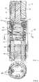
- FIG. 1shows a wrist 10 connected between a distal end effector 12 and a proximal tool shaft or main tube 14 for a surgical tool.
- the end effector 12 shownincludes grips 16 mounted on a distal clevis 18, as best seen in FIG. 2 .
- the distal clevis 18includes side access slots 20 that house distal crimps 22 of a plurality of wires or cables 24 that connect proximally to hypotubes 26, which extend through a platform or guide 30 and the interior of the tool shaft 14.
- the guide 30orients the hypotubes 26 and wire assembly, and is attached the tool shaft 14 of the instrument.
- the guide 30also initiates the rolling motion of the wrist 10 as the tool shaft 14 is moved in roll.
- the side access slots 20conveniently allow the crimps 22 to be pressed into place.
- other ways of attaching the wires 24 to the distal clevis 18, such as laser welding,may be employed in other embodiments.
- FIGS. 2 and 3show four wires 24, but a different number of wires may be used in another embodiment.
- the wires 24may be made of nitinol or other suitable materials.
- the wires 24create the joint of the wrist 10, and are rigidly attached between the distal clevis 18 and the hypotubes 26.
- a wire wrap 34is wrapped around the wires 24 similar to a coil spring and extends between the distal clevis 18 and the hypotubes 26.
- the shrink tube 36covers the wire wrap 34 and portions of the distal clevis 18 and the guide 30.
- the wire wrap 34 and shrink tube 36keep the wires 24 at fixed distances from each other when the hypotubes 26 are pushed and pulled to cause the wrist 10 to move in pitch and yaw.
- the wire wrap and shrink tubecan be configured in different ways in other embodiments (one preferred embodiment is shown in Fig. 27 and described in Section J below). For example, they can be converted into a five-lumen extrusion with the wires 24 as an internal part.
- the function of the wire wrap or an equivalent structureis to keep the wires 24 at a constant distance from the center line as the wrist 10 moves in roll, pitch, and/or yaw.
- the shrink tubecan also provide electrical isolation.
- FIG. 4shows a wrist 40 that includes a tube 42 having holes or lumens 43 distributed around the circumference to receive actuation cables or wires 44, which may be made of nitinol.
- the tube 42is flexible to permit bending in pitch and yaw by pulling the cables 44.
- the wrist 40preferably includes a rigid distal termination disk 41 (as shown in an alternative embodiment of Fig. 4B ) or other reinforcement that is substantially more rigid than the flexible tube 42 to evenly distribute cable forces to the flexible tube 42.
- the hollow center of the tube 42provides room for end effector cables such as gripping cables. There are typically at least four lumens.
- An inner spring 47may be provided.
- FIG. 4shows twelve lumens for the specific embodiment to accommodate six cables 44 making U-turns 45 at the distal end of the tube 42.
- the high number of cables usedallows the tube 42 to have a higher stiffness for the same cable pulling force to achieve the same bending in pitch and yaw.
- the use of twelve cables instead of four cablesmeans the tube 42 can be three times as stiff for the same cable pulling force.
- the use of twelve cables instead of four cableswill reduce the cable pulling force required by a factor of three.
- a reinforced distal termination plate 41may be included to distribute cable forces more smoothly over the tube 42.
- the proximal ends of the cables 44may be connected to an actuator mechanism, such as an assembly including a gimbal plate 46 that is disclosed in U.S. Patent Application No. 10/187,248, filed on June 27, 2002 .
- This mechanismfacilitates the actuation of a selected plurality of cables in a coordinated manner for control of a bendable or steerable member, such as controlling the flexible wrist bending angle and direction.
- the example of an actuator mechanism of Application No. 10/187,248can be adapted to actuate a large number of peripheral cables in a proportionate manner so as to provide a coordinated steering of a flexible member without requiring a comparably large number of linear actuators.
- a separately controlled linear actuation mechanismmay be used to tension each cable or cable pairs looped over a pulley and moved with a rotary actuator, the steering being controlled by coordinating the linear actuators.
- the tube 42typically may be made of a plastic material or an elastomer with a sufficiently low modulus of elasticity to permit adequate bending in pitch and yaw, and may be manufactured by a multi-lumen extrusion to include the plurality of lumens, e.g., twelve lumens. It is desirable for the tube to have a high bending stiffness to limit undesirable deflections such as S-shape bending, but this increases the cable forces needed for desirable bending in pitch and yaw. As discussed below, one can use a larger number of cables than necessary to manipulate the wrist in pitch and yaw (i.e., more than three cables) in order to provide sufficiently high cable forces to overcome the high bending stiffness of the tube.
- FIGS. 4A and 4Bshow schematically an example of two different cable arrangements in a wrist embodiment similar to that shown in FIG. 4 . Note that for constant total cable cross-sectional area, including cables in pairs and including a greater number of proportionately smaller cables both permit the cables to terminate at a greater lateral offset relative to the wrist centerline.
- FIGS. 4A and 4Bshow a plan view and an elevational view respectively of a wrist embodiment, split by a dividing line such that the right side of each figure shows a wrist Example 1, and the left side of each figure shows a wrist Example 2.
- the tube 42has the same outside radius R and inside radius r defining the central lumen.
- the anchor 44.5may be a swaged bead or other conventional cable anchor.
- the edges of the distal termination plate 41' at the opening of lumens 43'may be rounded to reduce stress concentration, and the loop 45 may be partially or entirely countersunk into the distal termination plate 41.
- the diameters of the sixteen cables 44'are 1 ⁇ 2 the diameters of the four cables 44, so that the total cross-sectional cable area is the same in each example.
- the employment of termination loop 45eliminates the distal volume devoted to a cable anchor 44.5, and tends to permit the cable lumen 43' to be closer to the radius R of the tube 42 than the cable lumen 43.
- the smaller diameter of each cable 44'brings the cable centerline closer to the outer edge of the cable lumen 43'.
- Both of these propertiespermit the cables in Example 2 to act about a larger moment arm L2 relative to the center of tube 42 than the corresponding moment arm L1 of Example 1.
- This greater moment arm L2permits lower cable stresses for the same overall bending moment on the tube 42 (permitting longer cable life or a broader range of optional cable materials), or alternatively, a larger bending moment for the same cable stresses (permitting greater wrist positioning stiffness).
- smaller diameter cablesmay be more flexible than comparatively thicker cables.
- a preferred embodiment of the wrist 40includes more that three cables, preferably at least 6 (e.g., three pairs of looped cables) and more preferably twelve or more.
- the anchor or termination point shown at the distal termination plate 41is exemplary, and the cables may be terminated (by anchor or loop) to bear directly on the material of the tube 42 if the selected material properties are suitable for the applied stresses.
- the cablesmay extend distally beyond the tube 42 and/or the distal termination plate 41 to terminate by connection to a more distal end effector member (not shown), the cable tension being sufficiently biased to maintain the end effector member securely connected to the wrist 40 within the operational range of wrist motion.
- the tube 50includes a plurality of cutouts 52 on two sides and alternating in two orthogonal directions to facilitate bending in pitch and yaw, respectively.
- a plurality of lumens 54are distributed around the circumference to accommodate actuation cables.
- the tube 60is formed as an outer boot wrapped around an interior spring 62 which is formed of a higher stiffness material than that for the tube 60.
- the tube 60includes interior slots 64 to receive actuation cables. Providing a separately formed flexible tube can simplify assembly. Such a tube is easier to extrude, or otherwise form, than a tube with holes for passing through cables.
- the tubealso lends itself to using actuation cables with preformed termination structures or anchors, since the cables can be put in place from the central lumen, and then the inner spring inserted inside the cables to maintain spacing and retention of the cables.
- the tube 60may be a single use component that is sterile but not necessarily autoclavable.
- FIG. 7shows a tube 70 having cutouts 72 which may be similar to the cutouts 52 in the tube 50 of FIG. 5.
- the tube 70may be made of plastic or metal.
- An outer cover 74is placed around the tube 50.
- the outer cover 74may be a Kapton cover or the like, and is typically a high modulus material with wrinkles that fit into the cutouts 72.
- FIGS. 8 and 9show a wrist 80 having a plurality of flexible, axially sliding members 82 that are connected or interlocked to each other by an axial tongue and groove connection 84 to form a tubular wrist 80.
- Each sliding member 82forms a longitudinal segment of the tube 80.
- the axial connection 84allows the sliding members 82 to slide axially relative to each other, while maintaining the lateral position of each member relative to the wrist longitudinal centerline.
- Each sliding member 82includes a hole or lumen 86 for receiving an actuation cable, which is terminated adjacent the distal end of the wrist 80.
- FIG. 9illustrates bending of the wrist 80 under cable pulling forces of the cables 90 as facilitated by sliding motion of the sliding members 82.
- the cables 90extend through the tool shaft 92 and are connected proximally to an actuation mechanism, such as a gimbal plate 94 for actuation.
- the sliding members 82bend by different amounts due to the difference in the radii of curvature for the sliding members 82during bending of the wrist 80.
- an embodiment of a wrist having axially sliding membersmay have integrated cables and sliding members, for example whereby the sliding members are integrally formed around the cables (e.g., by extrusion) as integrated sliding elements, or whereby an actuation mechanism couples to the proximal ends of the sliding members, the sliding members transmitting forces directly to the distal end of the wrist.
- FIG. 13shows a wrist 130 having a plurality of axial members 132 that are typically made of a flexible plastic material.
- the axial members 132may be co-extruded over the cables 134, so that the cables can be metal and still be isolated.
- the axial members 132may be connected to each other by an axial tongue and groove connection 136 to form a tubular wrist 130.
- the axial members 132may be allowed to slide relative to each other during bending of the wrist 130 in pitch and yaw.
- the wrist 130is similar to the wrist 80 of FIG. 8 but has a slightly different configuration and the components have different shapes.
- FIGS. 10 and 11show a wrist 100 formed by a plurality of axial springs 102 arranged around a circumference to form a tubular wrist 100.
- the springs 102are coil springs wound in the same direction or, more likely, in opposite directions.
- a cable 104extends through the overlap region of each pair of adjacent springs 102, as more clearly seen in FIG. 11 . Due to the overlap, the solid height of the wrist 100 would be twice the solid height of an individual spring 102, if the wrist is fully compressed under cable tension.
- the springs 102are typically preloaded in compression so that the cables are not slack and to increase wrist stability.
- the springsare biased to a fully compressed solid height state by cable pre-tension when the wrist is neutral or in an unbent state.
- a controlled, coordinated decrease in cable tension or cable release on one side of the wristpermits one side to expand so that the springs on one side of the wrist 100 expand to form the outside radius of the bent wrist 100.
- the wristis returned to the straight configuration upon reapplication of the outside cable pulling force.
- the springsare biased to a partially compressed state by cable pre-tension when the wrist is neutral or in an unbent state.
- a controlled, coordinated increase in cable tension or cable pulling on one side of the wristpermits that side to contract so that the springs on one side of wrist 100 shorten to form the inside radius of the bent wrist 100.
- thiscan be combined with a release of tension on the outside radius, as in the first alternative above.
- the wristis returned to the straight configuration upon restoration of the original cable pulling force.
- FIG. 12shows a wrist in the form of a wave spring 120 having a plurality of wave spring segments or components 122 which are stacked or wound to form a tubular, wave spring wrist 120.
- the wave springis formed and wound from a continuous piece of flat wire in a quasi-helical fashion, wherein the waveform is varied each cycle so that high points of one cycle contact the low points of the next.
- Such springsare commercially available, for instance, from the Smalley Spring Company. Holes are formed in the wave spring wrist 120 to receive actuation cables.
- a plurality of separate disk-like wave spring segmentsmay be strung bead-fashion on the actuator cables (retained by the cables or bonded to one another).
- the wave spring segments 122 as illustratedeach have two opposite high points and two opposite low points which are spaced by 90 degrees. This configuration facilitates bending in pitch and yaw.
- the wave spring segments 122may have other configurations such as a more dense wave pattern with additional high points and low points around the circumference of the wrist 120.
- FIG. 14shows several segments or disks 142 of the wrist 140.
- An interior spring 144is provided in the interior space of the disks 142, while a plurality of cables or wires 145 are used to bend the wrist 140 in pitch and yaw.
- the disks 142are threaded or coupled onto the inner spring 144, which acts as a lumen for pulling cables for an end effector.
- the inner spring 144provides axial stiffness, so that the forces applied through the pulling cables to the end effector do not distort the wrist 140.
- stacked solid spacerscan be used instead of the spring 144 to achieve this function.
- the disks 142each include a curved outer mating surface 146 that mates with a curved inner mating surface 148 of the adjacent disk.
- the disks 142may be made of plastic or ceramic, for example.
- the friction between the spherical mating surfaces 146, 148preferably is not strong enough to interfere with the movement of the wrist 140.
- One way to alleviate this potential problemis to select an appropriate interior spring 144 that would bear some compressive loading and prevent excessive compressive loading on the disks 142 during actuation of the cables 145 to bend the wrist 140.
- the interior spring 144may be made of silicone rubber or the like.
- An additional silicon member 150may surround the actuation cables as well.
- the separate disks 142may be replaced by one continuous spiral strip.
- each cable in the wrist 160may be housed in a spring wind 162 as illustrated in FIGS. 16 and 17 .
- An interior spring 164is also provided.
- the disks 170can be made without the annular flange and holes to receive the cables (as in the disks 142 in FIGS. 14 and 15 ).
- the solid mandrel wires 172 inside of the spring winds 162can be placed in position along the perimeters of the disks 170.
- a center wire mandrel 174is provided in the middle for winding the interior spring 164.
- the assemblycan be potted in silicone or the like, and then the mandrel wires 172, 174 can be removed.
- Some form of cover or the likecan be used to prevent the silicone from sticking to the spherical mating surfaces of the disks 170.
- the small mandrel springs 172will be wound to leave a small gap (instead of solid height) to provide room for shrinking as the wrist 160 bends.
- the siliconedesirably is bonded sufficiently well to the disks 170 to provide torsional stiffness to the bonded assembly of the disks 170 and springs 172, 174.
- the insulative silicone materialmay serve as cautery insulation for a cautery tool that incorporates the wrist 160.
- FIG. 18shows a wrist 180 having a plurality of disks 182 separated by elastomer members 184.
- the elastomer members 184may be annular members, or may include a plurality of blocks distributed around the circumference of the disks 182.
- an interior spring 186is provided in the interior space of the disks 182 and the elastomer members 184, while a plurality of cables or wires 188 are used to bend the wrist 180 in pitch and yaw.
- the disks 182are threaded or coupled onto the inner spring 184, which acts as a lumen for pulling cables for an end effector.
- the inner spring 184provides axial stiffness, so that the forces applied through the pulling cables to the end effector do not distort the wrist 180.
- the configuration of this wrist 180is more analogous to a human spine than the wrist 140.
- the elastomer members 184resiliently deform to permit bending of the wrist 180 in pitch and yaw.
- the use of the elastomer members 184eliminates the need for mating surfaces between the disks 182 and the associated frictional forces.
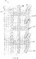
- FIG. 19shows a wrist 190 including a plurality of disks 192 supported by alternating beams or ribs 194, 196 oriented in orthogonal directions to facilitate pitch and yaw bending of the wrist 190.
- the wrist 190may be formed from a tube by removing cut-outs between adjacent disks 192 to leave alternating layers of generally orthogonal ribs 194, 196 between the adjacent disks 192.
- the disks 192have holes 198 for actuation cables to pass therethrough.
- the disks 192 and ribs 194, 196may be made of a variety of material such as steel, aluminum, nitinol, or plastic.
- the disks 202include slots 204 instead of holes for receiving the cables. Such a tube is easier to extrude than a tube with holes for passing through cables.
- a spring 206is wound over the disks 202 to support the cables.
- the wrist 210includes disks 212 supported by alternating beams or ribs 214, 216 having cuts or slits 217 on both sides of the ribs into the disks 212 to make the ribs 214, 216 longer than the spacing between the disks 212.
- This configurationmay facilitate bending with a smaller radius of curvature than that of the wrist 190 in FIG. 19 for the same wrist length, or achieve the same radius of curvature using a shorter wrist.
- a bending angle of about 15 degrees between adjacent disks 212is typical in these embodiments.
- the disks 212have holes 218 for receiving actuation cables.
- FIG. 22shows a portion of a wrist 220 including a coil spring 222 with a plurality of thin disks 224 distributed along the length of the spring 222. Only two disks 224 are seen in the wrist portion of FIG. 22 , including 224A and 224B which are oriented with tabs 226 that are orthogonal to each other, as illustrated in FIGS. 23 and 24 .
- the spring 222coils at solid height except for gaps which are provided for inserting the disks 224 therein.
- the spring 222is connected to the disks 224 near the inner edge and the tabs 226 of the disks 224.
- the disks 224may be formed by etching, and include holes 228 for receiving actuation cables.
- the tabs 226act as the fulcrum to allow the spring 222 to bend at certain points during bending of the wrist 220 in pitch and yaw.
- the disks 224may be relatively rigid in some embodiments, but may be flexible enough to bend and act as spring elements during bending of the wrist 220 in other embodiments.
- a silicone outer covermay be provided around the coil spring 222 and disks 224 as a dielectric insulator.
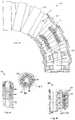
- the spring 222 and disks 224 assemblymay be protected by an outer structure formed, for example, from outer pieces or armor pieces 250 FIGS. 25 and 26 .
- Each armor piece 250includes an outer mating surface 252 and an inner mating surface 254.
- the outer mating surface 252 of one armor piece 250mates with the inner mating surface 254 of an adjacent armor piece 250.
- the armor pieces 250are stacked along the length of the spring 222, and maintain contact as they rotate from the bending of the wrist 220.
- the flexible wristdepends upon the stiffness of the various materials relative to the applied loads for accuracy. That is, the stiffer the materials used and/or the shorter the length of the wrist and/or the larger diameter the wrist has, the less sideways deflection there will be for the wrist under a given surgical force exerted. If the pulling cables have negligible compliance, the angle of the end of the wrist can be determined accurately, but there can be a wandering or sideways deflection under a force that is not counteracted by the cables. If the wrist is straight and such a force is exerted, for example, the wrist may take on an S-shape deflection. One way to counteract this is with suitable materials of sufficient stiffness and appropriate geometry for the wrist.
- Another wayis to have half of the pulling cables terminate halfway along the length of the wrist and be pulled half as far as the remaining cables, as described in U.S. Patent Application No. 10/187,248 . Greater resistance to the S-shape deflection comes at the expense of the ability to withstand moments. Yet another way to avoid the S-shape deflection is to provide a braided cover on the outside of the wrist.
- FIG. 27shows a wrist 270 having a tube 272 that is wrapped in outer wires 274.
- the wires 274are each wound to cover about 360 degree rotation between the ends of the tube 272.
- the outer wires 274can be wound to form a braided covering over the tube 272.
- two sets of wires including a right-handed set and a left-handed seti.e., one clockwise and one counter-clockwise
- the weaving or plaitingprevents the clockwise and counterclockwise wires from moving radially relative to each other.
- the torsional stiffnessis created, for example, because under twisting, one set of wires will want to grow in diameter while the other set shrinks.
- the braidingprevents one set from being different from the other, and the torsional deflection is resisted. It is desirable to make the lay length of the outer wires 274 equal to the length of the wrist 270 so that each individual wire of the braid does not have to increase in length as the wrist 270 bends in a circular arc, although the outer wires 274 will need to slide axially.
- the braidwill resist S-shape deflection of the wrist 270 because it would require the outer wires 274 to increase in length.
- the braidmay also protect the wrist from being gouged or cut acting as armor.
- the braided coveris non-conductive, it may be the outermost layer and act as an armor of the wrist 270. Increased torsional stiffness and avoidance of S-shape deflection of the wrist can also be accomplished by layered springs starting with a right hand wind that is covered by a left hand wind and then another right hand wind. The springs would not be interwoven.
- FIGS. 28 and 29show additional examples of wrist covers.
- the wrist cover 280is formed by a flat spiral of non-conductive material, such as plastic or ceramic. When the wrist is bent, the different coils of the spiral cover 280 slide over each other.
- FIG. 29shows a wrist cover 290 that includes bent or curled edges 292 to ensure overlap between adjacent layers of the spiral.
- the wrist cover 300may include ridges or grooves 302 oriented parallel to the axis of the wrist. The ridges 302 act as a spline from one spiral layer to the next, and constitute a torsional stabilizer for the wrist. Add discussion of nitinol laser cover configured like stents.
Landscapes
- Health & Medical Sciences (AREA)
- Life Sciences & Earth Sciences (AREA)
- Surgery (AREA)
- Engineering & Computer Science (AREA)
- Heart & Thoracic Surgery (AREA)
- Biomedical Technology (AREA)
- Nuclear Medicine, Radiotherapy & Molecular Imaging (AREA)
- Medical Informatics (AREA)
- Molecular Biology (AREA)
- Animal Behavior & Ethology (AREA)
- General Health & Medical Sciences (AREA)
- Public Health (AREA)
- Veterinary Medicine (AREA)
- Physics & Mathematics (AREA)
- Biophysics (AREA)
- Optics & Photonics (AREA)
- Pathology (AREA)
- Radiology & Medical Imaging (AREA)
- Robotics (AREA)
- Rehabilitation Therapy (AREA)
- Ophthalmology & Optometry (AREA)
- Reproductive Health (AREA)
- Plasma & Fusion (AREA)
- Otolaryngology (AREA)
- Vascular Medicine (AREA)
- Gynecology & Obstetrics (AREA)
- Pregnancy & Childbirth (AREA)
- Surgical Instruments (AREA)
- Manipulator (AREA)
Abstract
Description
- This application is based on and claims the benefit of
U.S. Provisional Patent Application No. 60/431,636, filed December 6, 2002 U.S. Patent Application No. 10/187,248 , entitled "Surgical Tool Having Positively Positionable Tendon-Actuated Multi-Disk Wrist Joint," filed on June 28, 2002;U.S. Patent Application No. 10/186,176 - PCT International Application No.
PCT/US98/19508 WO99/50721 U.S. Patent Application No. 09/418,726 U.S. Patent Application No. 60/111,711 U.S. Patent Application No. 09/378,173 U.S. Patent Application No. 09/398,507 , entitled "Master Having Redundant Degrees of Freedom", filed on September 17, 1999;U.S. Application No. 09/399,457 U.S. Patent Application No. 09/373,678 U.S. Patent Application No. 09/398,958 U.S. Patent No. 5,808,665 , entitled "Endoscopic Surgical Instrument and Method for Use", issued on September 15, 1998.WO 92/19147 A1 EP 0 764 423 A1 discloses a bendable tube comprised of pieces having connecting noses.US 2002/120178 A1 discloses an endoscope with a guiding apparatus having a flexible and passively manipulated proximal portion and a tracking rod or guide.DE 42 34 833 A1US 6 077 287 A discloses a disposable surgical instrument having a flexible actuated cable which transmits force to a movable part to effect pivotal movement of the movable part.US 6 270 453 B1 discloses a bending device for an examining insertion tube comprising wires linking cylindrical members in tubular shape.- The present invention relates generally to surgical tools and, more particularly, to flexible wrist mechanisms in surgical tools for performing robotic surgery.
- Advances in minimally invasive surgical technology could dramatically increase the number of surgeries performed in a minimally invasive manner. Minimally invasive medical techniques are aimed at reducing the amount of extraneous tissue that is damaged during diagnostic or surgical procedures, thereby reducing patient recovery time, discomfort, and deleterious side effects. The average length of a hospital stay for a standard surgery may also be shortened significantly using minimally invasive surgical techniques. Thus, an increased adoption of minimally invasive techniques could save millions of hospital days, and millions of dollars annually in hospital residency costs alone. Patient recovery times, patient discomfort, surgical side effects, and time away from work may also be reduced with minimally invasive surgery.
- The most common form of minimally invasive surgery may be endoscopy. Probably the most common form of endoscopy is laparoscopy, which is minimally invasive inspection and surgery inside the abdominal cavity. In standard laparoscopic surgery, a patient's abdomen is insufflated with gas, and cannula sleeves are passed through small (approximately 1/2 inch) incisions to provide entry ports for laparoscopic surgical instruments. The laparoscopic surgical instruments generally include a laparoscope (for viewing the surgical field) and working tools. The working tools are similar to those used in conventional (open) surgery, except that the working end or end effector of each tool is separated from its handle by an extension tube. As used herein, the term "end effector" means the actual working part of the surgical instrument and can include clamps, graspers, scissors, staplers, and needle holders, for example. To perform surgical procedures, the surgeon passes these working tools or instruments through the cannula sleeves to an internal surgical site and manipulates them from outside the abdomen. The surgeon monitors the procedure by means of a monitor that displays an image of the surgical site taken from the laparoscope. Similar endoscopic techniques are employed in, e.g., arthroscopy, retroperitoneoscopy, pelviscopy, nephroscopy, cystoscopy, cisternoscopy, sinoscopy, hysteroscopy, urethroscopy and the like.
- There are many disadvantages relating to current minimally invasive surgical (MIS) technology. For example, existing MIS instruments deny the surgeon the flexibility of tool placement found in open surgery. Most current laparoscopic tools have rigid shafts, so that it can be difficult to approach the worksite through the small incision. Additionally, the length and construction of many endoscopic instruments reduces the surgeon's ability to feel forces exerted by tissues and organs on the end effector of the associated tool. The lack of dexterity and sensitivity of endoscopic tools is a major impediment to the expansion of minimally invasive surgery.
- Minimally invasive telesurgical robotic systems are being developed to increase a surgeon's dexterity when working within an internal surgical site, as well as to allow a surgeon to operate on a patient from a remote location. In a telesurgery system, the surgeon is often provided with an image of the surgical site at a computer workstation. While viewing a three-dimensional image of the surgical site on a suitable viewer or display, the surgeon performs the surgical procedures on the patient by manipulating master input or control devices of the workstation. The master controls the motion of a servomechanically operated surgical instrument. During the surgical procedure, the telesurgical system can provide mechanical actuation and control of a variety of surgical instruments or tools having end effectors such as, e.g., tissue graspers, needle drivers, or the like, that perform various functions for the surgeon, e.g., holding or driving a needle, grasping a blood vessel, or dissecting tissue, or the like, in response to manipulation of the master control devices.
- Some surgical tools employ a roll-pitch-yaw mechanism for providing three degrees of rotational movement to an end effector around three perpendicular axes. The pitch and yaw rotations are typically provided by a wrist mechanism coupled between a shaft of the tool and an end effector, and the roll rotation is typically provided by rotation of the shaft. At about 90° pitch, the yaw and roll rotational movements overlap, resulting in the loss of one degree of rotational movement, referred to as a singularity.
- The present invention is directed to alternative embodiments of a tool having a wrist mechanism that provides pitch and yaw rotation in such a way that the tool has no singularity in roll, pitch, and yaw. The wrist mechanism has a flexible tubular structure which may be formed by a flexible tube or a series of disks connected to a spring or similar flexible component. Actuation cables or flexible wires (e.g., made of nitinol) extend through the wrist mechanism, and are used to bend the flexible wrist in pitch and yaw rotation. The rotation in roll is provided by turning a tool shaft to which the wrist mechanism is attached.
- In accordance with an aspect of the present invention, a wrist mechanism includes a minimally invasive surgical instrument comprises an elongate shaft having a working end, a proximal end, and a shaft axis between the working end and the proximal end; and an end effector. A wrist member has a flexible tube and an inner spring which include proximal portions connected to the working end of the elongate shaft and distal portions connected to the end effector. The inner spring is disposed inside an interior cavity of the flexible tube, and has an axis which is parallel to an axis of the flexible tube. A plurality of actuation cables (or wires) have distal portions connected to the end effector and extend from the distal portion through the wrist member toward the elongate shaft to proximal portions which are actuatable to bend the wrist member in pitch rotation and yaw rotation. If actuation wires are used they may also help support the end effector.
- In some embodiments, the actuation cables are disposed inside a hollow interior of the inner spring. At least three actuation cables are connected to the end effector. The proximal portions of the actuation cables are connected to a gimbal plate configured to actuate the actuation cables, and the gimbal plate is disposed proximal of the proximal end of the elongate shaft. The actuation cables may be disposed between the inner spring and the flexible tube. The flexible tube may include interior axial slots bounded by an external surface of the inner spring to form lumens for receiving the actuation cables. The flexible tube may include a plurality of transverse cut-outs which are generally transverse to the axis of the flexible tube.
- In accordance with another aspect of the invention, a minimally invasive surgical instrument comprises an elongate shaft having a working end, a proximal end, and a shaft axis between the working end and the proximal end; and an end effector. A wrist member has a flexible tube including an axis extending through an interior surrounded by a wall. The wall of the flexible tube includes a plurality of lumens oriented generally parallel to the axis of the flexible tube. The wrist member has a proximal portion connected to the working end of the elongate shaft and a distal portion connected to the end effector. A plurality of actuation cables have distal portions connected to the end effector and extend from the distal portion through the lumens of the wall of the wrist member toward the elongate shaft to proximal portions which are actuatable to bend the wrist member in pitch rotation and yaw rotation.
- In some embodiments, the wall of the flexible tube includes twelve lumens. Each actuation cable is looped around a distal portion of the wall of the flexible tube to extend through two adjacent lumens. The flexible tube includes a plurality of transverse cut-outs which are generally transverse to the axis of the flexible tube. An outer cover is wrapped around an external surface of the flexible tube. The transverse cut-outs comprise alternating layers of cut-outs each having a pair of cut-outs which are disposed opposite to one another. The cut-outs of each layer are oriented in a direction which is spaced by about 90 degrees from the cut-outs of an adjacent layer. The transverse cut-outs leave ribs connected between disk portions above and below the ribs. Slits extending generally along the axis of the flexible tube into the disk portions may be provided on both sides of the ribs.
- In specific embodiments, the flexible tube comprises an inner tube having a plurality of slots oriented generally parallel to the axis of the flexible tube and an outer cover wrapped around the inner tube to form the lumens at the slots. The outer cover comprises an exterior spring. The flexible tube may comprise a plurality of springs each disposed around one of the plurality of slots. An inner spring may be disposed around the interior of the flexible tube. A braided cover may be formed on an exterior surface of the flexible tube. The braided cover has a first set of wires wound in a clockwise direction between a proximal end and a distal end of the flexible tube and a second set of wires wound in a counter-clockwise direction between the proximal end and the distal end of the flexible tube and interwoven with the first set of wires.
- In some embodiments, the flexible tube comprises a plurality of axial sliding members which are slidably connected with each other by an axial connection generally parallel to the axis of the flexible tube. The axial connection comprises a tongue and groove connection. Each axial sliding member includes a lumen for receiving one of the actuation cables in another version. The flexible tube comprises a plurality of axial springs coupled with each other and disposed around a circumference of the flexible tube. Each axial spring has coils which overlap with coils of an adjacent axial spring to provide one of the lumens for receiving one of the actuation cables. The flexible tube may comprise a wave spring having a plurality of wave spring segments which include high points and low points connected in series along the axis of the flexible tube. The high points of one wave spring segment are connected to the low points of an adjacent wave spring segment.
- In accordance with another aspect of the present invention, a minimally invasive surgical instrument comprises an elongate shaft having a working end, a proximal end, and a shaft axis between the working end and the proximal end; and an end effector. A wrist member has an inner spring which includes a proximal portion connected to the working end of the elongate shaft and a distal portion connected to the end effector. The wrist member has a plurality of annular disks distributed along an axis of the inner spring. The annular disks each have an inside edge connected with the inner spring. A plurality of actuation cables have distal portions connected to the end effector and extend from the distal portion through the wrist member toward the elongate shaft to proximal portions which are actuatable to bend the wrist member in pitch rotation and yaw rotation.
- In some embodiments, the disks include a plurality of holes through which the actuation cables extend. The disks each include a pair of inner tabs disposed opposite from one another and extending from the inside edge into a gap between coils of the inner spring. Adjacent disks are oriented with the inner tabs of one disk disposed about 90 degrees apart from the inner tabs of the adjacent disk. The disks each include an outer mating surface and an inner mating surface for mating between adjacent disks, the outer mating surface of one disk mating with the inner mating surface of the adjacent disk. The outer mating surface and the inner mating surface are generally spherical in shape. A plurality of elastomer members each disposed between and connected with adjacent disks. A wrist cover is disposed outside of the inner spring and the annular disks. The wrist cover comprises a flat spiral of non-conductive material. The flat spiral includes curled edges which overlap between adjacent layers of the spiral. The flat spiral includes grooves oriented generally parallel to the axis of the inner spring.
FIG. 1 is a perspective of a surgical tool according to an embodiment of the invention;FIG. 2 is a cross-sectional view of a wrist according to an embodiment of the present invention;FIG. 3 is cross-sectional view of the wrist ofFIG. 2 along III-III;FIG. 4 is a perspective view of a wrist according to another embodiment of the invention;FIGS. 4A and 4B are, respectively, a plan view and an elevation view of a distal portion of an example of a wrist similar to that ofFIG. 4 , showing details of the cable arrangement;- FIG. 5 is a perspective view of a wrist according to another embodiment of the invention;
FIG. 6 is a plan view of a wrist according to another embodiment of the invention;FIG. 7 is a cross-sectional view of a wrist according to another embodiment of the invention;FIG. 8 is a plan view of a wrist according to another embodiment of the invention;FIG. 9 is an elevational view of the wrist ofFIG. 8 with a tool shaft and a gimbal plate;FIG. 10 is a plan view of a wrist according to another embodiment of the invention;FIG. 11 is an elevational view of the wrist ofFIG. 10 ;FIG. 12 is an elevational view of a wrist according to another embodiment of the invention;FIG. 13 is a plan view of a wrist according to another embodiment of the invention;FIG. 14 is a cross-sectional view of a portion of a wrist according to another embodiment of the invention;FIG. 15 is a partial sectional view of the wrist ofFIG. 14 in bending;FIG. 16 is a perspective view of a wrist according to another embodiment of the invention;FIG. 17 is a plan view of the wrist ofFIG. 16 ;FIG. 18 is a cross-sectional view of a portion of a wrist according to another embodiment of the invention;FIG. 19 is a perspective view of a wrist according to another embodiment of the invention;FIG. 20 is a plan view of a wrist according to another embodiment of the invention;FIG. 21 is a perspective view of a wrist according to another embodiment of the invention;FIG. 22 is a cross-sectional view of a portion of a wrist according to another embodiment of the invention;FIGS. 23 and 24 are plan views of the disks in the wrist ofFIG. 22 ;FIG. 25 is a perspective view of an outer piece for the wrist ofFIG. 22 ;FIG. 26 is a cross-sectional view of the outer piece ofFIG. 25 ;FIG. 27 is a perspective view of a wrist according to another embodiment of the invention;FIG. 28 is an cross-sectional view of a wrist cover according to an embodiment of the invention;FIG. 29 is an cross-sectional view of a wrist cover according to another embodiment of the invention; andFIG. 30 is a perspective view of a portion of a wrist cover according to another embodiment of the invention.- As used herein, "end effector" refers to an actual working distal part that is manipulable by means of the wrist member for a medical function, e.g., for effecting a predetermined treatment of a target tissue. For instance, some end effectors have a single working member such as a scalpel, a blade, or an electrode. Other end effectors have a pair or plurality of working members such as forceps, graspers, scissors, or clip appliers, for example. In certain embodiments, the disks or vertebrae are configured to have openings which collectively define a longitudinal lumen or space along the wrist, providing a conduit for any one of a number of alternative elements or instrumentalities associated with the operation of an end effector. Examples include conductors for electrically activated end effectors (e.g., electrosurgical electrodes; transducers, sensors, and the like); conduits for fluids, gases or solids (e.g., for suction, insufflation, irrigation, treatment fluids, accessory introduction, biopsy extraction and the like); mechanical elements for actuating moving end effector members (e.g., cables, flexible elements or articulated elements for operating grips, forceps, scissors); wave guides; sonic conduction elements; fiberoptic elements; and the like. Such a longitudinal conduit may be provided with a liner, insulator or guide element such as a elastic polymer tube; spiral wire wound tube or the like.
- As used herein, the terms "surgical instrument", "instrument", "surgical tool", or "tool" refer to a member having a working end which carries one or more end effectors to be introduced into a surgical site in a cavity of a patient, and is actuatable from outside the cavity to manipulate the end effector(s) for effecting a desired treatment or medical function of a target tissue in the surgical site. The instrument or tool typically includes a shaft carrying the end effector(s) at a distal end, and is preferably servomechanically actuated by a telesurgical system for performing functions such as holding or driving a needle, grasping a blood vessel, and dissecting tissue.
- The various embodiments of the flexible wrist described herein are intended to be relatively inexpensive to manufacture and be capable of use for cautery, although they are not limited to use for cautery. For MIS applications, the diameter of the insertable portion of the tool is small, typically about 12mm or less, and preferably about 5mm or less, so as to permit small incisions. It should be understood that while the examples described in detail illustrate this size range, the embodiments may be scaled to include larger or smaller instruments.
- Some of the wrist embodiments employ a series of disks or similar elements that move in a snake-like manner when bent in pitch and yaw (e.g.,
FIGS. 14 and22 ). The disks are annular disks and may have circular inner and outer diameters. Typically, those wrists each include a series of disks, for example, about thirteen disks, which may be about 0.005 inch to about 0.030 inch thick, etched stainless steel disks. Thinner disks maybe used in the middle, while thicker disks are desirable for the end regions for additional strength to absorb cable forces such as those that are applied at the cable U-turns around the end disk. The end disk may include a counter bore (e.g., about 0.015 inch deep) into which the center spring fits to transfer the load from the cables into compression of the center spring. The disks may be threaded onto an inner spring, which acts as a lumen for pulling cables for an end effector such as a gripper, a cautery connection, or a tether to hold a tip thereon. The inner spring also provides axial stiffness, so that the gripper or tether forces do not distort the wrist. In some embodiments, the disks include a pair of oppositely disposed inner tabs or tongues which are captured by the inner spring. The inner spring is at solid height (the wires of successive helix pitches lie in contact with one another when the spring is undeflected), except at places where the tabs of the disks are inserted to create gaps in the spring. The disks alternate in direction of the tabs to allow for alternating pitch and yaw rotation. A typical inner spring is made with a 0.01 inch diameter wire, and adjacent disks are spaced from one another by four spring coils. If the spring is made of edge wound flat wire (like a slinky), high axial force can be applied by the cables without causing neighboring coils to hop over each other. - In some embodiments, each disk has twelve evenly spaced holes for receiving actuation cables. Three cables are sufficient to bend the wrist in any desired direction, the tensions on the individual cables being coordinated to produce the desired bending motion. Due to the small wrist diameter and the moments exerted on the wrist by surgical forces, the stress in the three cables will be quite large. More than three cables are typically used to reduce the stress in each cable (including additional cables which are redundant for purposes of control). In some examples illustrated below, twelve or more cables are used (see discussion of
FIG. 4 below). To drive the cables, a gimbal plate or rocking plate may be used. The gimbal plate utilizes two standard inputs to manipulate the cables to bend the wrist at arbitrary angles relative to the pitch and yaw axes. - Some wrists are formed from a tubular member that is sufficiently flexible to bend in pitch and yaw (e.g.,
FIGS. 2 and4 ). An inner spring may be included. The tubular member may include cut-outs to reduce the structural stiffness to facilitate bending (e.g.,FIGS. 5 and19 ). One way to make the wrist is to insert wire and hypotube mandrels in the center hole and the actuation wire holes. A mold can be made, and the assembly can be overmolded with a two-part platinum cure silicone rubber cured in the oven (e.g., at about 165°C). The mandrels are pulled out after molding to create channels to form the center lumen and peripheral lumens for the pulling cables. In this way, the wrist has no exposed metal parts. The rubber can withstand autoclave and can withstand the elongation during wrist bending, which is typically about 30% strain. - In specific embodiments, the tubular member includes a plurality of axial sliding members each having a lumen for receiving an actuation cable (e.g.,
FIG. 8 ). The tubular member may be formed by a plurality of axial springs having coils which overlap with the coils of adjacent springs to provide lumens for receiving the actuation cables (e.g.,FIG. 10 ). The tubular member may be formed by a stack of wave springs (e.g.,FIG. 12 ). The lumens in the tubular member may be formed by interiors of axial springs (e.g.,FIG. 16 ). The exterior of the tubular member may be braided to provide torsional stiffness (e.g.,FIG. 27 ). FIG. 1 shows awrist 10 connected between adistal end effector 12 and a proximal tool shaft ormain tube 14 for a surgical tool. Theend effector 12 shown includesgrips 16 mounted on adistal clevis 18, as best seen inFIG. 2 . Thedistal clevis 18 includesside access slots 20 that housedistal crimps 22 of a plurality of wires orcables 24 that connect proximally to hypotubes 26, which extend through a platform or guide 30 and the interior of thetool shaft 14. Theguide 30 orients the hypotubes 26 and wire assembly, and is attached thetool shaft 14 of the instrument. Theguide 30 also initiates the rolling motion of thewrist 10 as thetool shaft 14 is moved in roll. Theside access slots 20 conveniently allow thecrimps 22 to be pressed into place. Of course, other ways of attaching thewires 24 to thedistal clevis 18, such as laser welding, may be employed in other embodiments.FIGS. 2 and 3 show fourwires 24, but a different number of wires may be used in another embodiment. Thewires 24 may be made of nitinol or other suitable materials. Thewires 24 create the joint of thewrist 10, and are rigidly attached between thedistal clevis 18 and thehypotubes 26. Awire wrap 34 is wrapped around thewires 24 similar to a coil spring and extends between thedistal clevis 18 and thehypotubes 26. Theshrink tube 36 covers thewire wrap 34 and portions of thedistal clevis 18 and theguide 30. Thewire wrap 34 and shrinktube 36 keep thewires 24 at fixed distances from each other when thehypotubes 26 are pushed and pulled to cause thewrist 10 to move in pitch and yaw. They also provide torsional and general stiffness to thewrist 10 to allow it to move in roll with thetool shaft 14 and to resist external forces. The wire wrap and shrink tube can be configured in different ways in other embodiments (one preferred embodiment is shown inFig. 27 and described in Section J below). For example, they can be converted into a five-lumen extrusion with thewires 24 as an internal part. The function of the wire wrap or an equivalent structure is to keep thewires 24 at a constant distance from the center line as thewrist 10 moves in roll, pitch, and/or yaw. The shrink tube can also provide electrical isolation.FIG. 4 shows awrist 40 that includes atube 42 having holes orlumens 43 distributed around the circumference to receive actuation cables orwires 44, which may be made of nitinol. Thetube 42 is flexible to permit bending in pitch and yaw by pulling thecables 44. Thewrist 40 preferably includes a rigid distal termination disk 41 (as shown in an alternative embodiment ofFig. 4B ) or other reinforcement that is substantially more rigid than theflexible tube 42 to evenly distribute cable forces to theflexible tube 42. The hollow center of thetube 42 provides room for end effector cables such as gripping cables. There are typically at least four lumens. Aninner spring 47 may be provided.FIG. 4 shows twelve lumens for the specific embodiment to accommodate sixcables 44 makingU-turns 45 at the distal end of thetube 42. The high number of cables used allows thetube 42 to have a higher stiffness for the same cable pulling force to achieve the same bending in pitch and yaw. For example, the use of twelve cables instead of four cables means thetube 42 can be three times as stiff for the same cable pulling force. Alternatively, if the stiffness of thetube 42 remains the same, the use of twelve cables instead of four cables will reduce the cable pulling force required by a factor of three. Note that although the material properties and cable stress levels may permit the U-turns 45 to bear directly on the end of thetube 42, a reinforceddistal termination plate 41 may be included to distribute cable forces more smoothly over thetube 42. The proximal ends of thecables 44 may be connected to an actuator mechanism, such as an assembly including agimbal plate 46 that is disclosed inU.S. Patent Application No. 10/187,248, filed on June 27, 2002 10/187,248 - The
tube 42 typically may be made of a plastic material or an elastomer with a sufficiently low modulus of elasticity to permit adequate bending in pitch and yaw, and may be manufactured by a multi-lumen extrusion to include the plurality of lumens, e.g., twelve lumens. It is desirable for the tube to have a high bending stiffness to limit undesirable deflections such as S-shape bending, but this increases the cable forces needed for desirable bending in pitch and yaw. As discussed below, one can use a larger number of cables than necessary to manipulate the wrist in pitch and yaw (i.e., more than three cables) in order to provide sufficiently high cable forces to overcome the high bending stiffness of the tube. FIGS. 4A and 4B show schematically an example of two different cable arrangements in a wrist embodiment similar to that shown inFIG. 4 . Note that for constant total cable cross-sectional area, including cables in pairs and including a greater number of proportionately smaller cables both permit the cables to terminate at a greater lateral offset relative to the wrist centerline.FIGS. 4A and 4B show a plan view and an elevational view respectively of a wrist embodiment, split by a dividing line such that the right side of each figure shows a wrist Example 1, and the left side of each figure shows a wrist Example 2. In each example thetube 42 has the same outside radius R and inside radius r defining the central lumen.- In Example 1, the number of
cables 44 in the wrist 40.1 is equal to four (n1 = 4) with each cable individually terminated by a distal anchor 44.5, set in a countersunk bore in thedistal termination plate 41, each cable extending through a respectivelateral cable lumen 43 in thedistal termination plate 41 and theflexible tube 42. The anchor 44.5 may be a swaged bead or other conventional cable anchor. - In Example 2, the number of cables 44' in the wrist 40.2 is equal to sixteen (n2 = 16), with the cables arranged as eight symmetrically spaced pairs of portions 44', each pair terminated by a distal "U-turn"
end loop 45 bearing on the distal termination plate 41' between adjacent cable lumens 43'. The edges of the distal termination plate 41' at the opening of lumens 43' may be rounded to reduce stress concentration, and theloop 45 may be partially or entirely countersunk into thedistal termination plate 41. The diameters of the sixteen cables 44' are ½ the diameters of the fourcables 44, so that the total cross-sectional cable area is the same in each example. - Comparing Examples 1 and 2, the employment of
termination loop 45 eliminates the distal volume devoted to a cable anchor 44.5, and tends to permit the cable lumen 43' to be closer to the radius R of thetube 42 than thecable lumen 43. In addition, the smaller diameter of each cable 44' brings the cable centerline closer to the outer edge of the cable lumen 43'. Both of these properties permit the cables in Example 2 to act about a larger moment arm L2 relative to the center oftube 42 than the corresponding moment arm L1 of Example 1. This greater moment arm L2 permits lower cable stresses for the same overall bending moment on the tube 42 (permitting longer cable life or a broader range of optional cable materials), or alternatively, a larger bending moment for the same cable stresses (permitting greater wrist positioning stiffness). In addition, smaller diameter cables may be more flexible than comparatively thicker cables. Thus a preferred embodiment of thewrist 40 includes more that three cables, preferably at least 6 (e.g., three pairs of looped cables) and more preferably twelve or more. - Note that the anchor or termination point shown at the
distal termination plate 41 is exemplary, and the cables may be terminated (by anchor or loop) to bear directly on the material of thetube 42 if the selected material properties are suitable for the applied stresses. Alternatively, the cables may extend distally beyond thetube 42 and/or thedistal termination plate 41 to terminate by connection to a more distal end effector member (not shown), the cable tension being sufficiently biased to maintain the end effector member securely connected to thewrist 40 within the operational range of wrist motion. - One way to reduce the stiffness of the tube structurally is to provide cutouts, as shown inFIG. 5. The
tube 50 includes a plurality ofcutouts 52 on two sides and alternating in two orthogonal directions to facilitate bending in pitch and yaw, respectively. A plurality oflumens 54 are distributed around the circumference to accommodate actuation cables. - In another embodiment illustrated in
FIG. 6 , thetube 60 is formed as an outer boot wrapped around aninterior spring 62 which is formed of a higher stiffness material than that for thetube 60. Thetube 60 includesinterior slots 64 to receive actuation cables. Providing a separately formed flexible tube can simplify assembly. Such a tube is easier to extrude, or otherwise form, than a tube with holes for passing through cables. The tube also lends itself to using actuation cables with preformed termination structures or anchors, since the cables can be put in place from the central lumen, and then the inner spring inserted inside the cables to maintain spacing and retention of the cables. In some cases, thetube 60 may be a single use component that is sterile but not necessarily autoclavable. FIG. 7 shows atube 70 havingcutouts 72 which may be similar to thecutouts 52 in thetube 50 ofFIG. 5. Thetube 70 may be made of plastic or metal. Anouter cover 74 is placed around thetube 50. Theouter cover 74 may be a Kapton cover or the like, and is typically a high modulus material with wrinkles that fit into thecutouts 72.FIGS. 8 and 9 show awrist 80 having a plurality of flexible, axially slidingmembers 82 that are connected or interlocked to each other by an axial tongue andgroove connection 84 to form atubular wrist 80. Each slidingmember 82 forms a longitudinal segment of thetube 80. Theaxial connection 84 allows the slidingmembers 82 to slide axially relative to each other, while maintaining the lateral position of each member relative to the wrist longitudinal centerline. Each slidingmember 82 includes a hole orlumen 86 for receiving an actuation cable, which is terminated adjacent the distal end of thewrist 80.FIG. 9 illustrates bending of thewrist 80 under cable pulling forces of thecables 90 as facilitated by sliding motion of the slidingmembers 82. Thecables 90 extend through thetool shaft 92 and are connected proximally to an actuation mechanism, such as agimbal plate 94 for actuation. The slidingmembers 82 bend by different amounts due to the difference in the radii of curvature for the sliding members 82during bending of thewrist 80. Alternatively, an embodiment of a wrist having axially sliding members may have integrated cables and sliding members, for example whereby the sliding members are integrally formed around the cables (e.g., by extrusion) as integrated sliding elements, or whereby an actuation mechanism couples to the proximal ends of the sliding members, the sliding members transmitting forces directly to the distal end of the wrist.FIG. 13 shows awrist 130 having a plurality ofaxial members 132 that are typically made of a flexible plastic material. Theaxial members 132 may be co-extruded over thecables 134, so that the cables can be metal and still be isolated. Theaxial members 132 may be connected to each other by an axial tongue andgroove connection 136 to form atubular wrist 130. Theaxial members 132 may be allowed to slide relative to each other during bending of thewrist 130 in pitch and yaw. Thewrist 130 is similar to thewrist 80 ofFIG. 8 but has a slightly different configuration and the components have different shapes.FIGS. 10 and 11 show awrist 100 formed by a plurality ofaxial springs 102 arranged around a circumference to form atubular wrist 100. Thesprings 102 are coil springs wound in the same direction or, more likely, in opposite directions. Acable 104 extends through the overlap region of each pair ofadjacent springs 102, as more clearly seen inFIG. 11 . Due to the overlap, the solid height of thewrist 100 would be twice the solid height of anindividual spring 102, if the wrist is fully compressed under cable tension. Thesprings 102 are typically preloaded in compression so that the cables are not slack and to increase wrist stability.- In one alternative, the springs are biased to a fully compressed solid height state by cable pre-tension when the wrist is neutral or in an unbent state. A controlled, coordinated decrease in cable tension or cable release on one side of the wrist permits one side to expand so that the springs on one side of the
wrist 100 expand to form the outside radius of thebent wrist 100. The wrist is returned to the straight configuration upon reapplication of the outside cable pulling force. - In another alternative, the springs are biased to a partially compressed state by cable pre-tension when the wrist is neutral or in an unbent state. A controlled, coordinated increase in cable tension or cable pulling on one side of the wrist permits that side to contract so that the springs on one side of
wrist 100 shorten to form the inside radius of thebent wrist 100. Optionally this can be combined with a release of tension on the outside radius, as in the first alternative above. The wrist is returned to the straight configuration upon restoration of the original cable pulling force. FIG. 12 shows a wrist in the form of awave spring 120 having a plurality of wave spring segments orcomponents 122 which are stacked or wound to form a tubular,wave spring wrist 120. In one embodiment, the wave spring is formed and wound from a continuous piece of flat wire in a quasi-helical fashion, wherein the waveform is varied each cycle so that high points of one cycle contact the low points of the next. Such springs are commercially available, for instance, from the Smalley Spring Company. Holes are formed in thewave spring wrist 120 to receive actuation cables. Alternatively, a plurality of separate disk-like wave spring segments may be strung bead-fashion on the actuator cables (retained by the cables or bonded to one another).- The
wave spring segments 122 as illustrated each have two opposite high points and two opposite low points which are spaced by 90 degrees. This configuration facilitates bending in pitch and yaw. Of course, thewave spring segments 122 may have other configurations such as a more dense wave pattern with additional high points and low points around the circumference of thewrist 120. FIG. 14 shows several segments ordisks 142 of thewrist 140. Aninterior spring 144 is provided in the interior space of thedisks 142, while a plurality of cables orwires 145 are used to bend thewrist 140 in pitch and yaw. Thedisks 142 are threaded or coupled onto theinner spring 144, which acts as a lumen for pulling cables for an end effector. Theinner spring 144 provides axial stiffness, so that the forces applied through the pulling cables to the end effector do not distort thewrist 140. In alternative embodiments, stacked solid spacers can be used instead of thespring 144 to achieve this function. Thedisks 142 each include a curvedouter mating surface 146 that mates with a curvedinner mating surface 148 of the adjacent disk.FIG. 15 illustrates bending of thewrist 140 with associated relative rotation between thedisks 142. Thedisks 142 may be made of plastic or ceramic, for example. The friction between the spherical mating surfaces 146, 148 preferably is not strong enough to interfere with the movement of thewrist 140. One way to alleviate this potential problem is to select an appropriateinterior spring 144 that would bear some compressive loading and prevent excessive compressive loading on thedisks 142 during actuation of thecables 145 to bend thewrist 140. Theinterior spring 144 may be made of silicone rubber or the like. Anadditional silicon member 150 may surround the actuation cables as well. In alternate embodiments, theseparate disks 142 may be replaced by one continuous spiral strip.- In alternate embodiments, each cable in the
wrist 160 may be housed in aspring wind 162 as illustrated inFIGS. 16 and 17 . Aninterior spring 164 is also provided. Thedisks 170 can be made without the annular flange and holes to receive the cables (as in thedisks 142 inFIGS. 14 and15 ). The solid mandrel wires 172 inside of the spring winds 162 can be placed in position along the perimeters of thedisks 170. A center wire mandrel 174 is provided in the middle for winding theinterior spring 164. The assembly can be potted in silicone or the like, and then the mandrel wires 172, 174 can be removed. Some form of cover or the like can be used to prevent the silicone from sticking to the spherical mating surfaces of thedisks 170. The small mandrel springs 172 will be wound to leave a small gap (instead of solid height) to provide room for shrinking as thewrist 160 bends. The silicone desirably is bonded sufficiently well to thedisks 170 to provide torsional stiffness to the bonded assembly of thedisks 170 and springs 172, 174. The insulative silicone material may serve as cautery insulation for a cautery tool that incorporates thewrist 160. FIG. 18 shows awrist 180 having a plurality ofdisks 182 separated byelastomer members 184. Theelastomer members 184 may be annular members, or may include a plurality of blocks distributed around the circumference of thedisks 182. Similar to thewrist 140 ofFIG. 14 , an interior spring 186 is provided in the interior space of thedisks 182 and theelastomer members 184, while a plurality of cables orwires 188 are used to bend thewrist 180 in pitch and yaw. Thedisks 182 are threaded or coupled onto theinner spring 184, which acts as a lumen for pulling cables for an end effector. Theinner spring 184 provides axial stiffness, so that the forces applied through the pulling cables to the end effector do not distort thewrist 180. The configuration of thiswrist 180 is more analogous to a human spine than thewrist 140. Theelastomer members 184 resiliently deform to permit bending of thewrist 180 in pitch and yaw. The use of theelastomer members 184 eliminates the need for mating surfaces between thedisks 182 and the associated frictional forces.FIG. 19 shows awrist 190 including a plurality ofdisks 192 supported by alternating beams orribs wrist 190. Thewrist 190 may be formed from a tube by removing cut-outs betweenadjacent disks 192 to leave alternating layers of generallyorthogonal ribs adjacent disks 192. Thedisks 192 haveholes 198 for actuation cables to pass therethrough. Thedisks 192 andribs wrist 200 as illustrated inFIG. 20 , thedisks 202 includeslots 204 instead of holes for receiving the cables. Such a tube is easier to extrude than a tube with holes for passing through cables. Aspring 206 is wound over thedisks 202 to support the cables.- In
FIG. 21 , thewrist 210 includesdisks 212 supported by alternating beams orribs disks 212 to make theribs disks 212. This configuration may facilitate bending with a smaller radius of curvature than that of thewrist 190 inFIG. 19 for the same wrist length, or achieve the same radius of curvature using a shorter wrist. A bending angle of about 15 degrees betweenadjacent disks 212 is typical in these embodiments. Thedisks 212 have holes 218 for receiving actuation cables. FIG. 22 shows a portion of awrist 220 including acoil spring 222 with a plurality of thin disks 224 distributed along the length of thespring 222. Only two disks 224 are seen in the wrist portion ofFIG. 22 , including 224A and 224B which are oriented withtabs 226 that are orthogonal to each other, as illustrated inFIGS. 23 and 24 . Thespring 222 coils at solid height except for gaps which are provided for inserting the disks 224 therein. Thespring 222 is connected to the disks 224 near the inner edge and thetabs 226 of the disks 224. The disks 224 may be formed by etching, and includeholes 228 for receiving actuation cables. Thetabs 226 act as the fulcrum to allow thespring 222 to bend at certain points during bending of thewrist 220 in pitch and yaw. The disks 224 may be relatively rigid in some embodiments, but may be flexible enough to bend and act as spring elements during bending of thewrist 220 in other embodiments. A silicone outer cover may be provided around thecoil spring 222 and disks 224 as a dielectric insulator. In addition, thespring 222 and disks 224 assembly may be protected by an outer structure formed, for example, from outer pieces orarmor pieces 250FIGS. 25 and 26 . Eacharmor piece 250 includes anouter mating surface 252 and aninner mating surface 254. Theouter mating surface 252 of onearmor piece 250 mates with theinner mating surface 254 of anadjacent armor piece 250. Thearmor pieces 250 are stacked along the length of thespring 222, and maintain contact as they rotate from the bending of thewrist 220.- The flexible wrist depends upon the stiffness of the various materials relative to the applied loads for accuracy. That is, the stiffer the materials used and/or the shorter the length of the wrist and/or the larger diameter the wrist has, the less sideways deflection there will be for the wrist under a given surgical force exerted. If the pulling cables have negligible compliance, the angle of the end of the wrist can be determined accurately, but there can be a wandering or sideways deflection under a force that is not counteracted by the cables. If the wrist is straight and such a force is exerted, for example, the wrist may take on an S-shape deflection. One way to counteract this is with suitable materials of sufficient stiffness and appropriate geometry for the wrist. Another way is to have half of the pulling cables terminate halfway along the length of the wrist and be pulled half as far as the remaining cables, as described in
U.S. Patent Application No. 10/187,248 . Greater resistance to the S-shape deflection comes at the expense of the ability to withstand moments. Yet another way to avoid the S-shape deflection is to provide a braided cover on the outside of the wrist. FIG. 27 shows awrist 270 having atube 272 that is wrapped inouter wires 274. Thewires 274 are each wound to cover about 360 degree rotation between the ends of thetube 272. To increase the torsional stiffness of thewrist 270 and avoid S-shape deflection of thewrist 270, theouter wires 274 can be wound to form a braided covering over thetube 272. To form the braided covering, two sets of wires including a right-handed set and a left-handed set (i.e., one clockwise and one counter-clockwise) are interwoven. The weaving or plaiting prevents the clockwise and counterclockwise wires from moving radially relative to each other. The torsional stiffness is created, for example, because under twisting, one set of wires will want to grow in diameter while the other set shrinks. The braiding prevents one set from being different from the other, and the torsional deflection is resisted. It is desirable to make the lay length of theouter wires 274 equal to the length of thewrist 270 so that each individual wire of the braid does not have to increase in length as thewrist 270 bends in a circular arc, although theouter wires 274 will need to slide axially. The braid will resist S-shape deflection of thewrist 270 because it would require theouter wires 274 to increase in length. Moreover, the braid may also protect the wrist from being gouged or cut acting as armor. If the braided cover is non-conductive, it may be the outermost layer and act as an armor of thewrist 270. Increased torsional stiffness and avoidance of S-shape deflection of the wrist can also be accomplished by layered springs starting with a right hand wind that is covered by a left hand wind and then another right hand wind. The springs would not be interwoven.- The above discloses some armors or covers for the wrists.
FIGS. 28 and 29 show additional examples of wrist covers. InFIG. 28 , the wrist cover 280 is formed by a flat spiral of non-conductive material, such as plastic or ceramic. When the wrist is bent, the different coils of the spiral cover 280 slide over each other.FIG. 29 shows awrist cover 290 that includes bent or curlededges 292 to ensure overlap between adjacent layers of the spiral. To provide torsional stiffness to the wrist, thewrist cover 300 may include ridges orgrooves 302 oriented parallel to the axis of the wrist. Theridges 302 act as a spline from one spiral layer to the next, and constitute a torsional stabilizer for the wrist. Add discussion of nitinol laser cover configured like stents. - The above-described arrangements of apparatus and methods are merely illustrative of applications of the principles of this invention and many other embodiments and modifications may be made without departing from the scope of the invention as defined in the claims. The scope of the invention should, therefore, be determined not with reference to the above description, but instead should be determined with reference to the appended claims along with their full scope of equivalents.
Claims (12)
- An apparatus comprising:a plurality of flexible axial members (82) laterally interlocked with each other to form a tube, wherein each axial member extends longitudinally from a proximal end to a distal end of the tube, and wherein the axial members are longitudinally slidable relative to each other;an elongate shaft (14) having a working end, a proximal end, and a shaft axis, the working end being coupled to a proximal end of the plurality of flexible axial members; andan end effector (12) coupled to a distal end of the plurality of flexible axial members.
- The apparatus of claim 1, wherein the plurality of flexible axial members are interlocked with each other in a tongue and groove connection.
- The apparatus of claim 1, wherein the plurality of flexible axial members are connected to each other at a distal end of the tube.
- The apparatus of claim 1, wherein the tube is bent such that a radius of curvature of a first one of the flexible axial members is different from a radius of curvature of a second one of the flexible axial members.
- The apparatus of claim 1, wherein the tube is bendable such that a radius of curvature of a first one of the flexible axial members is different from a radius of curvature of a second one of the flexible axial members.
- The apparatus of claim 1, further comprising a gimbal plate coupled to the plurality of flexible axial members.
- The apparatus of claim 1 further comprising:- an actuation mechanism at the proximal end of the elongate shaft; and
an actuation cable extending from the actuation mechanism through the elongate shaft and terminating at a particular one of the flexible axial members. - The apparatus of claim 7, wherein the actuation cable extends through and terminates at a distal end of the particular one of the flexible axial members.
- The apparatus of claim 1, further comprising an actuation mechanism coupled to longitudinally move at least one of the flexible axial members.
- The apparatus of claim 1, wherein at least one axial member comprises an integrated cable.
- The apparatus of claim 10, wherein each axial member is coextruded over an integrated cable.
- The apparatus of claim 1, the axial members comprising a flexible plastic material.
Applications Claiming Priority (4)
| Application Number | Priority Date | Filing Date | Title |
|---|---|---|---|
| US43163602P | 2002-12-06 | 2002-12-06 | |
| EP03790301AEP1575439B1 (en) | 2002-12-06 | 2003-12-02 | Flexible wrist for surgical tool |
| EP11002837.0AEP2359767B1 (en) | 2002-12-06 | 2003-12-02 | Flexible wrist for surgical tool |
| PCT/US2003/038462WO2004052171A2 (en) | 2002-12-06 | 2003-12-02 | Flexible wrist for surgical tool |
Related Parent Applications (3)
| Application Number | Title | Priority Date | Filing Date |
|---|---|---|---|
| EP11002837.0ADivisionEP2359767B1 (en) | 2002-12-06 | 2003-12-02 | Flexible wrist for surgical tool |
| EP11002837.0ADivision-IntoEP2359767B1 (en) | 2002-12-06 | 2003-12-02 | Flexible wrist for surgical tool |
| EP03790301ADivisionEP1575439B1 (en) | 2002-12-06 | 2003-12-02 | Flexible wrist for surgical tool |
Publications (2)
| Publication Number | Publication Date |
|---|---|
| EP2901959A1 EP2901959A1 (en) | 2015-08-05 |
| EP2901959B1true EP2901959B1 (en) | 2019-02-06 |
Family
ID=32507770
Family Applications (7)
| Application Number | Title | Priority Date | Filing Date |
|---|---|---|---|
| EP03790301ARevokedEP1575439B1 (en) | 2002-12-06 | 2003-12-02 | Flexible wrist for surgical tool |
| EP14193176.6AExpired - LifetimeEP2901959B1 (en) | 2002-12-06 | 2003-12-02 | Flexible wrist for surgical tool |
| EP14193159.2AExpired - LifetimeEP2901958B1 (en) | 2002-12-06 | 2003-12-02 | Flexible wrist for surgical tool |
| EP11002838.8AExpired - LifetimeEP2359768B1 (en) | 2002-12-06 | 2003-12-02 | Flexible wrist for surgical tool |
| EP11002837.0AExpired - LifetimeEP2359767B1 (en) | 2002-12-06 | 2003-12-02 | Flexible wrist for surgical tool |
| EP14193162.6AExpired - LifetimeEP2865351B1 (en) | 2002-12-06 | 2003-12-02 | Flexible wrist for surgical tool |
| EP18203019.7AWithdrawnEP3498213A3 (en) | 2002-12-06 | 2003-12-02 | Flexible wrist for surgical tool |
Family Applications Before (1)
| Application Number | Title | Priority Date | Filing Date |
|---|---|---|---|
| EP03790301ARevokedEP1575439B1 (en) | 2002-12-06 | 2003-12-02 | Flexible wrist for surgical tool |
Family Applications After (5)
| Application Number | Title | Priority Date | Filing Date |
|---|---|---|---|
| EP14193159.2AExpired - LifetimeEP2901958B1 (en) | 2002-12-06 | 2003-12-02 | Flexible wrist for surgical tool |
| EP11002838.8AExpired - LifetimeEP2359768B1 (en) | 2002-12-06 | 2003-12-02 | Flexible wrist for surgical tool |
| EP11002837.0AExpired - LifetimeEP2359767B1 (en) | 2002-12-06 | 2003-12-02 | Flexible wrist for surgical tool |
| EP14193162.6AExpired - LifetimeEP2865351B1 (en) | 2002-12-06 | 2003-12-02 | Flexible wrist for surgical tool |
| EP18203019.7AWithdrawnEP3498213A3 (en) | 2002-12-06 | 2003-12-02 | Flexible wrist for surgical tool |
Country Status (8)
| Country | Link |
|---|---|
| US (9) | US7320700B2 (en) |
| EP (7) | EP1575439B1 (en) |
| JP (12) | JP4486503B2 (en) |
| KR (4) | KR101087996B1 (en) |
| CN (2) | CN100389730C (en) |
| AT (1) | ATE551964T1 (en) |
| AU (1) | AU2003293353A1 (en) |
| WO (1) | WO2004052171A2 (en) |
Families Citing this family (385)
| Publication number | Priority date | Publication date | Assignee | Title |
|---|---|---|---|---|
| US7713190B2 (en)* | 1998-02-24 | 2010-05-11 | Hansen Medical, Inc. | Flexible instrument |
| US6626899B2 (en) | 1999-06-25 | 2003-09-30 | Nidus Medical, Llc | Apparatus and methods for treating tissue |
| US8768516B2 (en) | 2009-06-30 | 2014-07-01 | Intuitive Surgical Operations, Inc. | Control of medical robotic system manipulator about kinematic singularities |
| EP2005914B1 (en)* | 2000-07-20 | 2012-04-04 | CareFusion 2200, Inc. | Hand-actuated articulating surgical tool |
| US7766894B2 (en) | 2001-02-15 | 2010-08-03 | Hansen Medical, Inc. | Coaxial catheter system |
| US8414505B1 (en) | 2001-02-15 | 2013-04-09 | Hansen Medical, Inc. | Catheter driver system |
| US6817974B2 (en) | 2001-06-29 | 2004-11-16 | Intuitive Surgical, Inc. | Surgical tool having positively positionable tendon-actuated multi-disk wrist joint |
| US20060178556A1 (en) | 2001-06-29 | 2006-08-10 | Intuitive Surgical, Inc. | Articulate and swapable endoscope for a surgical robot |
| US7331967B2 (en)* | 2002-09-09 | 2008-02-19 | Hansen Medical, Inc. | Surgical instrument coupling mechanism |
| JP4384439B2 (en) | 2002-11-21 | 2009-12-16 | 富士機械製造株式会社 | Anti-substrate work machine, anti-substrate work system, and work head use preparation processing program for anti-substrate work machine |
| KR101087996B1 (en) | 2002-12-06 | 2011-12-01 | 인튜어티브 서지컬 인코포레이티드 | Minimally invasive surgical instruments |
| US8182417B2 (en)* | 2004-11-24 | 2012-05-22 | Intuitive Surgical Operations, Inc. | Articulating mechanism components and system for easy assembly and disassembly |
| US8562640B2 (en)* | 2007-04-16 | 2013-10-22 | Intuitive Surgical Operations, Inc. | Tool with multi-state ratcheted end effector |
| US7090637B2 (en)* | 2003-05-23 | 2006-08-15 | Novare Surgical Systems, Inc. | Articulating mechanism for remote manipulation of a surgical or diagnostic tool |
| US7410483B2 (en) | 2003-05-23 | 2008-08-12 | Novare Surgical Systems, Inc. | Hand-actuated device for remote manipulation of a grasping tool |
| US8100824B2 (en) | 2003-05-23 | 2012-01-24 | Intuitive Surgical Operations, Inc. | Tool with articulation lock |
| US8007511B2 (en) | 2003-06-06 | 2011-08-30 | Hansen Medical, Inc. | Surgical instrument design |
| US9002518B2 (en) | 2003-06-30 | 2015-04-07 | Intuitive Surgical Operations, Inc. | Maximum torque driving of robotic surgical tools in robotic surgical systems |
| US7976539B2 (en)* | 2004-03-05 | 2011-07-12 | Hansen Medical, Inc. | System and method for denaturing and fixing collagenous tissue |
| WO2005087128A1 (en) | 2004-03-05 | 2005-09-22 | Hansen Medical, Inc. | Robotic catheter system |
| US7828808B2 (en)* | 2004-06-07 | 2010-11-09 | Novare Surgical Systems, Inc. | Link systems and articulation mechanisms for remote manipulation of surgical or diagnostic tools |
| US7678117B2 (en) | 2004-06-07 | 2010-03-16 | Novare Surgical Systems, Inc. | Articulating mechanism with flex-hinged links |
| US7241290B2 (en) | 2004-06-16 | 2007-07-10 | Kinetic Surgical, Llc | Surgical tool kit |
| US8353897B2 (en)* | 2004-06-16 | 2013-01-15 | Carefusion 2200, Inc. | Surgical tool kit |
| US8075476B2 (en)* | 2004-07-27 | 2011-12-13 | Intuitive Surgical Operations, Inc. | Cannula system and method of use |
| US8057508B2 (en)* | 2004-07-28 | 2011-11-15 | Ethicon Endo-Surgery, Inc. | Surgical instrument incorporating an electrically actuated articulation locking mechanism |
| US7857183B2 (en)* | 2004-07-28 | 2010-12-28 | Ethicon Endo-Surgery, Inc. | Surgical instrument incorporating an electrically actuated articulation mechanism |
| US7410086B2 (en) | 2004-07-28 | 2008-08-12 | Ethicon Endo-Surgery, Inc. | Electroactive polymer-based actuation mechanism for circular stapler |
| US8905977B2 (en)* | 2004-07-28 | 2014-12-09 | Ethicon Endo-Surgery, Inc. | Surgical stapling instrument having an electroactive polymer actuated medical substance dispenser |
| US7879070B2 (en) | 2004-07-28 | 2011-02-01 | Ethicon Endo-Surgery, Inc. | Electroactive polymer-based actuation mechanism for grasper |
| US7407074B2 (en) | 2004-07-28 | 2008-08-05 | Ethicon Endo-Surgery, Inc. | Electroactive polymer-based actuation mechanism for multi-fire surgical fastening instrument |
| US9700334B2 (en) | 2004-11-23 | 2017-07-11 | Intuitive Surgical Operations, Inc. | Articulating mechanisms and link systems with torque transmission in remote manipulation of instruments and tools |
| US7785252B2 (en) | 2004-11-23 | 2010-08-31 | Novare Surgical Systems, Inc. | Articulating sheath for flexible instruments |
| US20060116697A1 (en)* | 2004-11-30 | 2006-06-01 | Esophyx, Inc. | Flexible transoral endoscopic gastroesophageal flap valve restoration device and method |
| US20060201130A1 (en)* | 2005-01-31 | 2006-09-14 | Danitz David J | Articulating mechanisms with joint assembly and manual handle for remote manipulation of instruments and tools |
| US7784663B2 (en)* | 2005-03-17 | 2010-08-31 | Ethicon Endo-Surgery, Inc. | Surgical stapling instrument having load sensing control circuitry |
| US9789608B2 (en) | 2006-06-29 | 2017-10-17 | Intuitive Surgical Operations, Inc. | Synthetic representation of a surgical robot |
| JP2009500086A (en) | 2005-07-01 | 2009-01-08 | ハンセン メディカル,インク. | Robotic guide catheter system |
| US8535217B2 (en)* | 2005-07-26 | 2013-09-17 | Ams Research Corporation | Methods and systems for treatment of prolapse |
| US20070066985A1 (en)* | 2005-09-16 | 2007-03-22 | Boston Scientific Scimed, Inc. | Tissue cutting devices having hemostasis capability and related methods |
| JP5072850B2 (en)* | 2005-11-02 | 2012-11-14 | インジェクティカ アーゲー | Implantable injection device |
| US9931108B2 (en)* | 2005-11-18 | 2018-04-03 | Steven Miller | System and method for influencing an anatomical structure |
| US9962066B2 (en) | 2005-12-30 | 2018-05-08 | Intuitive Surgical Operations, Inc. | Methods and apparatus to shape flexible entry guides for minimally invasive surgery |
| US7930065B2 (en) | 2005-12-30 | 2011-04-19 | Intuitive Surgical Operations, Inc. | Robotic surgery system including position sensors using fiber bragg gratings |
| GB0600170D0 (en)* | 2006-01-06 | 2006-02-15 | Oliver Crispin Robotics Ltd | Improvements in and relating to robotic arms |
| USD581050S1 (en)* | 2006-03-10 | 2008-11-18 | Medical Device Innovations Limited | Surgical instrument tip |
| USD623739S1 (en) | 2006-03-10 | 2010-09-14 | Medical Device Innovations Limited | Surgical instrument handle |
| USD622380S1 (en) | 2006-03-10 | 2010-08-24 | Medical Device Innovations Limited | Surgical instrument |
| US8105350B2 (en) | 2006-05-23 | 2012-01-31 | Cambridge Endoscopic Devices, Inc. | Surgical instrument |
| KR101477133B1 (en) | 2006-06-13 | 2014-12-29 | 인튜어티브 서지컬 인코포레이티드 | Minimally invasive surgical system |
| US7862554B2 (en) | 2007-04-16 | 2011-01-04 | Intuitive Surgical Operations, Inc. | Articulating tool with improved tension member system |
| US9561045B2 (en)* | 2006-06-13 | 2017-02-07 | Intuitive Surgical Operations, Inc. | Tool with rotation lock |
| US8409244B2 (en)* | 2007-04-16 | 2013-04-02 | Intuitive Surgical Operations, Inc. | Tool with end effector force limiter |
| US10008017B2 (en) | 2006-06-29 | 2018-06-26 | Intuitive Surgical Operations, Inc. | Rendering tool information as graphic overlays on displayed images of tools |
| US9718190B2 (en) | 2006-06-29 | 2017-08-01 | Intuitive Surgical Operations, Inc. | Tool position and identification indicator displayed in a boundary area of a computer display screen |
| US12357400B2 (en) | 2006-06-29 | 2025-07-15 | Intuitive Surgical Operations, Inc. | Synthetic representation of a surgical robot |
| US10258425B2 (en) | 2008-06-27 | 2019-04-16 | Intuitive Surgical Operations, Inc. | Medical robotic system providing an auxiliary view of articulatable instruments extending out of a distal end of an entry guide |
| ATE545374T1 (en)* | 2006-06-30 | 2012-03-15 | Bovie Medical Corp | SURGICAL INSTRUMENT WITH REMOVABLE TOOL ARRANGEMENT |
| US8029531B2 (en)* | 2006-07-11 | 2011-10-04 | Cambridge Endoscopic Devices, Inc. | Surgical instrument |
| US8973461B2 (en)* | 2006-07-31 | 2015-03-10 | Commissariat A L'energie Atomique | Jointed limb comprising fibres, and jointed structure and robot or haptic interface comprising such a jointed limb |
| US7708758B2 (en)* | 2006-08-16 | 2010-05-04 | Cambridge Endoscopic Devices, Inc. | Surgical instrument |
| US20100241136A1 (en)* | 2006-12-05 | 2010-09-23 | Mark Doyle | Instrument positioning/holding devices |
| WO2008076330A1 (en)* | 2006-12-15 | 2008-06-26 | Soteira, Inc. | Drills and methods for vertebrostenting |
| US20080249536A1 (en)* | 2007-02-15 | 2008-10-09 | Hansen Medical, Inc. | Interface assembly for controlling orientation of robotically controlled medical instrument |
| JP4975494B2 (en) | 2007-03-23 | 2012-07-11 | 富士通株式会社 | Imaging device |
| WO2008131303A2 (en) | 2007-04-20 | 2008-10-30 | Hansen Medical, Inc. | Optical fiber shape sensing systems |
| US20090138025A1 (en)* | 2007-05-04 | 2009-05-28 | Hansen Medical, Inc. | Apparatus systems and methods for forming a working platform of a robotic instrument system by manipulation of components having controllably rigidity |
| US9096033B2 (en) | 2007-06-13 | 2015-08-04 | Intuitive Surgical Operations, Inc. | Surgical system instrument sterile adapter |
| US9469034B2 (en) | 2007-06-13 | 2016-10-18 | Intuitive Surgical Operations, Inc. | Method and system for switching modes of a robotic system |
| US8620473B2 (en) | 2007-06-13 | 2013-12-31 | Intuitive Surgical Operations, Inc. | Medical robotic system with coupled control modes |
| US9869339B2 (en) | 2008-04-11 | 2018-01-16 | Flexdex, Inc. | End-effector jaw closure transmission systems for remote access tools |
| WO2009126955A2 (en) | 2008-04-11 | 2009-10-15 | The Regents Of The University Of Michigan | Minimal access tool |
| US10405936B2 (en) | 2008-04-11 | 2019-09-10 | The Regents Of The University Of Michigan | Parallel kinematic mechanisms with decoupled rotational motions |
| WO2009127236A1 (en)* | 2008-04-18 | 2009-10-22 | Fortimedix B.V. | An instrument for endoscopic applications or the like |
| RU2011102169A (en)* | 2008-06-27 | 2012-08-10 | Эллидженс Корпарейшен (Us) | FLEXIBLE Wrist ELEMENT, METHODS FOR ITS MANUFACTURE AND USE |
| US12239396B2 (en) | 2008-06-27 | 2025-03-04 | Intuitive Surgical Operations, Inc. | Medical robotic system providing an auxiliary view including range of motion limitations for articulatable instruments extending out of a distal end of an entry guide |
| US9204923B2 (en) | 2008-07-16 | 2015-12-08 | Intuitive Surgical Operations, Inc. | Medical instrument electronically energized using drive cables |
| US8968355B2 (en)* | 2008-08-04 | 2015-03-03 | Covidien Lp | Articulating surgical device |
| US8465475B2 (en) | 2008-08-18 | 2013-06-18 | Intuitive Surgical Operations, Inc. | Instrument with multiple articulation locks |
| US8161838B2 (en) | 2008-12-22 | 2012-04-24 | Intuitive Surgical Operations, Inc. | Method and apparatus for reducing at least one friction force opposing an axial force exerted through an actuator element |
| US8245594B2 (en)* | 2008-12-23 | 2012-08-21 | Intuitive Surgical Operations, Inc. | Roll joint and method for a surgical apparatus |
| US8858547B2 (en) | 2009-03-05 | 2014-10-14 | Intuitive Surgical Operations, Inc. | Cut and seal instrument |
| US8423182B2 (en) | 2009-03-09 | 2013-04-16 | Intuitive Surgical Operations, Inc. | Adaptable integrated energy control system for electrosurgical tools in robotic surgical systems |
| US12266040B2 (en) | 2009-03-31 | 2025-04-01 | Intuitive Surgical Operations, Inc. | Rendering tool information as graphic overlays on displayed images of tools |
| US9254123B2 (en) | 2009-04-29 | 2016-02-09 | Hansen Medical, Inc. | Flexible and steerable elongate instruments with shape control and support elements |
| US10080482B2 (en) | 2009-06-30 | 2018-09-25 | Intuitive Surgical Operations, Inc. | Compliant surgical device |
| US20110022078A1 (en) | 2009-07-23 | 2011-01-27 | Cameron Dale Hinman | Articulating mechanism |
| US9492927B2 (en) | 2009-08-15 | 2016-11-15 | Intuitive Surgical Operations, Inc. | Application of force feedback on an input device to urge its operator to command an articulated instrument to a preferred pose |
| ES2388867B1 (en)* | 2009-10-27 | 2013-09-18 | Universitat Politècnica De Catalunya | MINIMALLY INVASIVE LAPAROSCOPIC SURGERY CLAMPS. |
| KR102152042B1 (en) | 2009-11-13 | 2020-09-04 | 인튜어티브 서지컬 오퍼레이션즈 인코포레이티드 | Surgical tool with a compact wrist |
| EP2467065B1 (en) | 2009-11-13 | 2020-01-08 | Intuitive Surgical Operations, Inc. | End effector with redundant closing mechanisms |
| US20110118708A1 (en) | 2009-11-13 | 2011-05-19 | Intuitive Surgical Operations, Inc. | Double universal joint |
| EP2498710B1 (en) | 2009-11-13 | 2018-05-16 | Intuitive Surgical Operations, Inc. | Motor interface for parallel drive shafts within an independently rotating member |
| CN104188710B (en)* | 2009-12-10 | 2017-04-12 | 奥林巴斯株式会社 | Medical manipulator |
| US8887595B2 (en) | 2009-12-22 | 2014-11-18 | Intuitive Surgical Operations, Inc. | Instrument wrist with cycloidal surfaces |
| US10376331B2 (en)* | 2010-02-12 | 2019-08-13 | Intuitive Surgical Operations, Inc. | Sheaths for jointed instruments |
| US9089351B2 (en) | 2010-02-12 | 2015-07-28 | Intuitive Surgical Operations, Inc. | Sheath for surgical instrument |
| US20110213360A1 (en)* | 2010-02-26 | 2011-09-01 | Tyco Healthcare Group Lp | Tensioning Mechanism for Articulation Drive Cables |
| US8439912B2 (en) | 2010-02-26 | 2013-05-14 | Covidien Lp | De-tensioning mechanism for articulation drive cables |
| DE102010014435B4 (en)* | 2010-04-09 | 2015-11-19 | Olympus Winter & Ibe Gmbh | Electrosurgical laparoscopic instrument with electrical lead |
| US9033998B1 (en) | 2010-05-13 | 2015-05-19 | Titan Medical Inc. | Independent roll wrist mechanism |
| US8603077B2 (en) | 2010-05-14 | 2013-12-10 | Intuitive Surgical Operations, Inc. | Force transmission for robotic surgical instrument |
| US11278345B2 (en) | 2010-05-25 | 2022-03-22 | Covidien Lp | Accurate jaw closure force in a catheter based instrument |
| US9138284B2 (en) | 2010-07-09 | 2015-09-22 | Intuitive Surgical Operations, Inc. | Electrosurgical tool cover |
| WO2012020386A1 (en) | 2010-08-11 | 2012-02-16 | Ecole Polytechnique Federale De Lausanne (Epfl) | Mechanical positioning system for surgical instruments |
| CN105078524A (en)* | 2010-08-27 | 2015-11-25 | 伊顿株式会社 | Instrument for surgical operation |
| US9737687B2 (en) | 2010-09-22 | 2017-08-22 | The Johns Hopkins University | Cable-driven morphable manipulator |
| WO2013014621A2 (en) | 2011-07-27 | 2013-01-31 | Ecole Polytechnique Federale De Lausanne (Epfl) | Mechanical teleoperated device for remote manipulation |
| US12402960B2 (en) | 2010-10-11 | 2025-09-02 | Ecole Polytechnique Federale De Lausanne (Epfl) | Mechanical manipulator for surgical instruments |
| EP2627278B1 (en) | 2010-10-11 | 2015-03-25 | Ecole Polytechnique Fédérale de Lausanne (EPFL) | Mechanical manipulator for surgical instruments |
| US9060765B2 (en) | 2010-11-08 | 2015-06-23 | Bovie Medical Corporation | Electrosurgical apparatus with retractable blade |
| US9101379B2 (en) | 2010-11-12 | 2015-08-11 | Intuitive Surgical Operations, Inc. | Tension control in actuation of multi-joint medical instruments |
| US9055960B2 (en) | 2010-11-15 | 2015-06-16 | Intuitive Surgical Operations, Inc. | Flexible surgical devices |
| KR101075294B1 (en) | 2011-01-12 | 2011-10-19 | 정창욱 | Minimally invasive surgical instruments |
| US20120191079A1 (en) | 2011-01-20 | 2012-07-26 | Hansen Medical, Inc. | System and method for endoluminal and translumenal therapy |
| US8578810B2 (en) | 2011-02-14 | 2013-11-12 | Intuitive Surgical Operations, Inc. | Jointed link structures exhibiting preferential bending, and related methods |
| JP6518403B2 (en)* | 2011-02-18 | 2019-05-22 | インテュイティブ サージカル オペレーションズ, インコーポレイテッド | Fusion and cutting surgical instruments and related methods |
| KR101259701B1 (en) | 2011-03-24 | 2013-05-06 | 정창욱 | Instrument for Minimally Invasive Surgery Having Curved Shaft |
| EP2706932B1 (en)* | 2011-05-12 | 2018-03-28 | Imperial Innovations Limited | A surgical device |
| US9161771B2 (en) | 2011-05-13 | 2015-10-20 | Intuitive Surgical Operations Inc. | Medical instrument with snake wrist structure |
| KR101336381B1 (en)* | 2011-06-07 | 2013-12-04 | 정창욱 | Instrument for Minimally Invasive Surgery |
| US20130030363A1 (en) | 2011-07-29 | 2013-01-31 | Hansen Medical, Inc. | Systems and methods utilizing shape sensing fibers |
| US8945174B2 (en) | 2011-08-15 | 2015-02-03 | Intuitive Surgical Operations, Inc. | Medical instrument with flexible jaw mechanism |
| US20130046317A1 (en)* | 2011-08-15 | 2013-02-21 | Intuitive Surgical Operations, Inc. | Medical instrument with flexible wrist mechanism |
| KR101322030B1 (en)* | 2011-09-05 | 2013-10-28 | 주식회사 모바수 | Instrument for Minimally Invasive Surgery Having Articulation Unit Including Spherical Parts |
| US20130303944A1 (en) | 2012-05-14 | 2013-11-14 | Intuitive Surgical Operations, Inc. | Off-axis electromagnetic sensor |
| US10238837B2 (en) | 2011-10-14 | 2019-03-26 | Intuitive Surgical Operations, Inc. | Catheters with control modes for interchangeable probes |
| US9452276B2 (en) | 2011-10-14 | 2016-09-27 | Intuitive Surgical Operations, Inc. | Catheter with removable vision probe |
| US9387048B2 (en) | 2011-10-14 | 2016-07-12 | Intuitive Surgical Operations, Inc. | Catheter sensor systems |
| CN102525581B (en)* | 2011-10-25 | 2013-09-11 | 王小军 | Disposable purse-string forceps for laparoscope |
| US9211159B2 (en) | 2011-12-02 | 2015-12-15 | Ethicon Endo-Surgery, Inc. | Surgical devices with intracorporeal elbow joint |
| US9179927B2 (en) | 2011-12-02 | 2015-11-10 | Ethicon Endo-Surgery, Inc. | Surgical methods using a surgical device having a fixed angular orientation |
| US9131987B2 (en) | 2011-12-02 | 2015-09-15 | Ethicon Endo-Surgery, Inc. | Elbow assembly for surgical devices |
| US8617203B2 (en) | 2011-12-02 | 2013-12-31 | Ethicon Endo-Surgery, Inc. | Jaw assembly for surgical devices |
| US20130158525A1 (en)* | 2011-12-09 | 2013-06-20 | Adn International, Llc | Flexible channel surgical instruments |
| US8876806B2 (en) | 2012-01-09 | 2014-11-04 | Covidien Lp | Surgical instrument with articulating assembly |
| US9956042B2 (en) | 2012-01-13 | 2018-05-01 | Vanderbilt University | Systems and methods for robot-assisted transurethral exploration and intervention |
| US8419720B1 (en) | 2012-02-07 | 2013-04-16 | National Advanced Endoscopy Devices, Incorporated | Flexible laparoscopic device |
| US8556883B2 (en)* | 2012-02-27 | 2013-10-15 | Rafic Saleh | Medical surgical navigation sensor mounting system |
| WO2013146310A1 (en)* | 2012-03-28 | 2013-10-03 | テルモ株式会社 | Puncture instrument assembly |
| US9211134B2 (en) | 2012-04-09 | 2015-12-15 | Carefusion 2200, Inc. | Wrist assembly for articulating laparoscopic surgical instruments |
| WO2013158983A1 (en) | 2012-04-20 | 2013-10-24 | Vanderbilt University | Robotic device for establishing access channel |
| US9687303B2 (en) | 2012-04-20 | 2017-06-27 | Vanderbilt University | Dexterous wrists for surgical intervention |
| US9539726B2 (en)* | 2012-04-20 | 2017-01-10 | Vanderbilt University | Systems and methods for safe compliant insertion and hybrid force/motion telemanipulation of continuum robots |
| KR101405087B1 (en)* | 2012-04-27 | 2014-06-10 | 한양대학교 에리카산학협력단 | An articulation for surgical instrument |
| US11135026B2 (en) | 2012-05-11 | 2021-10-05 | Peter L. Bono | Robotic surgical system |
| CN104640514B (en) | 2012-09-17 | 2019-05-07 | 直观外科手术操作公司 | Method and system for assigning input devices to teleoperated surgical instrument functionality |
| US10864048B2 (en) | 2012-11-02 | 2020-12-15 | Intuitive Surgical Operations, Inc. | Flux disambiguation for teleoperated surgical systems |
| US10631939B2 (en) | 2012-11-02 | 2020-04-28 | Intuitive Surgical Operations, Inc. | Systems and methods for mapping flux supply paths |
| US20140148673A1 (en) | 2012-11-28 | 2014-05-29 | Hansen Medical, Inc. | Method of anchoring pullwire directly articulatable region in catheter |
| US10507066B2 (en) | 2013-02-15 | 2019-12-17 | Intuitive Surgical Operations, Inc. | Providing information of tools by filtering image areas adjacent to or on displayed images of the tools |
| US20140296869A1 (en)* | 2013-03-14 | 2014-10-02 | Intuitive Surgical Operations, Inc. | Surgical instrument shaft |
| US20140277334A1 (en) | 2013-03-14 | 2014-09-18 | Hansen Medical, Inc. | Active drives for robotic catheter manipulators |
| US9326822B2 (en) | 2013-03-14 | 2016-05-03 | Hansen Medical, Inc. | Active drives for robotic catheter manipulators |
| US9408669B2 (en) | 2013-03-15 | 2016-08-09 | Hansen Medical, Inc. | Active drive mechanism with finite range of motion |
| US20140276936A1 (en) | 2013-03-15 | 2014-09-18 | Hansen Medical, Inc. | Active drive mechanism for simultaneous rotation and translation |
| WO2014201538A1 (en) | 2013-06-19 | 2014-12-24 | Titan Medical Inc. | Articulated tool positioner and system employing same |
| JP6173089B2 (en) | 2013-07-24 | 2017-08-02 | オリンパス株式会社 | Control method for medical master-slave system |
| CN103340662B (en)* | 2013-08-02 | 2016-02-17 | 苏州天臣国际医疗科技有限公司 | Endo-GIA |
| USD749726S1 (en)* | 2013-08-15 | 2016-02-16 | Intuitive Surgical Operations, Inc. | Surgical instrument shaft with hole pattern |
| WO2015057990A1 (en) | 2013-10-18 | 2015-04-23 | Intuitive Surgical Operations, Inc. | Wrist mechanism for surgical instrument |
| US9295522B2 (en) | 2013-11-08 | 2016-03-29 | Covidien Lp | Medical device adapter with wrist mechanism |
| CN105813582B (en) | 2013-12-11 | 2019-05-28 | 柯惠Lp公司 | Wrist and jaw assemblies for robotic surgical systems |
| CN106659540B (en) | 2014-02-03 | 2019-03-05 | 迪斯塔莫申股份公司 | Mechanical teleoperated devices including interchangeable distal instruments |
| KR20230056068A (en)* | 2014-02-21 | 2023-04-26 | 인튜어티브 서지컬 오퍼레이션즈 인코포레이티드 | Articulatable members having constrained motion, and related devices and methods |
| CN111938820B (en)* | 2014-02-21 | 2024-12-10 | 直观外科手术操作公司 | Mechanical joints and related systems and methods |
| US10280951B2 (en) | 2014-03-02 | 2019-05-07 | Drexel University | Articulating devices |
| US10166061B2 (en) | 2014-03-17 | 2019-01-01 | Intuitive Surgical Operations, Inc. | Teleoperated surgical system equipment with user interface |
| US10285763B2 (en) | 2014-04-02 | 2019-05-14 | Intuitive Surgical Operations, Inc. | Actuation element guide with twisting channels |
| JP6752717B2 (en)* | 2014-04-02 | 2020-09-09 | インテュイティブ サージカル オペレーションズ, インコーポレイテッド | Working element guide with twisted passages |
| US10046140B2 (en) | 2014-04-21 | 2018-08-14 | Hansen Medical, Inc. | Devices, systems, and methods for controlling active drive systems |
| JP2017514608A (en) | 2014-05-05 | 2017-06-08 | バイカリアス サージカル インク. | Virtual reality surgical device |
| US10259129B2 (en)* | 2014-05-06 | 2019-04-16 | The Johns Hopkins University | Adjustable stiffness morphable manipulator |
| CN106659538B (en) | 2014-08-13 | 2019-05-10 | 柯惠Lp公司 | Robot-controlled gripping with mechanical advantages |
| EP3185808B1 (en) | 2014-08-27 | 2022-02-23 | DistalMotion SA | Surgical system for microsurgical techniques |
| ES2848100T3 (en) | 2014-09-04 | 2021-08-05 | Memic Innovative Surgery Ltd | Device control including mechanical arms |
| US11357483B2 (en) | 2014-09-26 | 2022-06-14 | Intuitive Surgical Operations, Inc. | Surgical instrument with flexible shaft and actuation element guide |
| WO2016097873A2 (en) | 2014-12-19 | 2016-06-23 | Distalmotion Sa | Articulated handle for mechanical telemanipulator |
| WO2016097871A1 (en) | 2014-12-19 | 2016-06-23 | Distalmotion Sa | Docking system for mechanical telemanipulator |
| WO2016097861A1 (en) | 2014-12-19 | 2016-06-23 | Distalmotion Sa | Sterile interface for articulated surgical instruments |
| EP3653145B1 (en) | 2014-12-19 | 2024-01-24 | DistalMotion SA | Reusable surgical instrument for minimally invasive procedures |
| EP3232951B1 (en) | 2014-12-19 | 2023-10-25 | DistalMotion SA | Surgical instrument with articulated end-effector |
| WO2016123147A1 (en) | 2015-01-28 | 2016-08-04 | Bovie Medical Corporation | Cold plasma electrosurgical apparatus with bent tip applicator |
| WO2016133633A1 (en) | 2015-02-19 | 2016-08-25 | Covidien Lp | Repositioning method of input device for robotic surgical system |
| WO2016144937A1 (en) | 2015-03-10 | 2016-09-15 | Covidien Lp | Measuring health of a connector member of a robotic surgical system |
| EP3282952B1 (en) | 2015-04-03 | 2019-12-25 | The Regents Of The University Of Michigan | Tension management apparatus for cable-driven transmission |
| EP3280337B1 (en) | 2015-04-09 | 2019-11-13 | DistalMotion SA | Articulated hand-held instrument |
| US10568709B2 (en) | 2015-04-09 | 2020-02-25 | Distalmotion Sa | Mechanical teleoperated device for remote manipulation |
| US10959788B2 (en) | 2015-06-03 | 2021-03-30 | Covidien Lp | Offset instrument drive unit |
| US10806531B2 (en) | 2015-06-12 | 2020-10-20 | Intuitive Surgical Operations, Inc. | User interfaces and displays for flux supply units |
| CA2987637C (en) | 2015-06-16 | 2023-10-03 | Covidien Lp | Robotic surgical system torque transduction sensing |
| EP3313315B1 (en) | 2015-06-23 | 2024-04-10 | Covidien LP | Robotic surgical assemblies |
| WO2017037532A1 (en) | 2015-08-28 | 2017-03-09 | Distalmotion Sa | Surgical instrument with increased actuation force |
| AU2016326371B2 (en) | 2015-09-25 | 2020-07-23 | Covidien Lp | Robotic surgical assemblies and instrument drive connectors thereof |
| CN108712886B (en) | 2015-10-02 | 2021-06-04 | 弗莱克斯德克斯公司 | Handle mechanism providing unlimited roll |
| US11896255B2 (en) | 2015-10-05 | 2024-02-13 | Flexdex, Inc. | End-effector jaw closure transmission systems for remote access tools |
| WO2017062516A1 (en) | 2015-10-05 | 2017-04-13 | Flexdex, Inc. | Medical devices having smoothly articulating multi-cluster joints |
| US10265058B2 (en) | 2015-10-19 | 2019-04-23 | DNP Biomed, LLC | Systems, devices, components and methods for displacing and repositioning the esophagus away from the heart during atrial ablation surgical procedures |
| US9668720B2 (en) | 2015-10-19 | 2017-06-06 | DNP Biomed, LLC | Systems, devices, components and methods for displacing and repositioning the esophagus away from the heart during atrial ablation surgical procedures |
| EP3878396A1 (en) | 2015-10-23 | 2021-09-15 | Covidien LP | Surgical system for detecting gradual changes in perfusion |
| EP3376988B1 (en) | 2015-11-19 | 2023-08-23 | Covidien LP | Optical force sensor for robotic surgical system |
| BR112018009251A2 (en)* | 2016-02-05 | 2019-04-09 | Board Of Regents Of The University Of Texas System | surgical apparatus and customized main controller for a surgical apparatus |
| KR102708262B1 (en) | 2016-02-05 | 2024-09-20 | 보드 오브 리전츠, 더 유니버시티 오브 텍사스 시스템 | The manipulatable intraruminal medical device |
| WO2017147607A1 (en) | 2016-02-25 | 2017-08-31 | Flexdex, Inc. | Parallel kinematic apparatuses |
| EP3422990A4 (en) | 2016-03-04 | 2019-11-13 | Covidien LP | REVERSE KINEMATIC CONTROL SYSTEMS FOR SURGICAL ROBOTIC SYSTEM |
| US10463438B2 (en) | 2016-03-09 | 2019-11-05 | Memic Innovative Surgery Ltd. | Modular device comprising mechanical arms |
| BR112018068122A2 (en) | 2016-03-10 | 2019-01-15 | Human Extensions Ltd | medical instrument and medical device control unit |
| US11576562B2 (en) | 2016-04-07 | 2023-02-14 | Titan Medical Inc. | Camera positioning method and apparatus for capturing images during a medical procedure |
| JP6662690B2 (en)* | 2016-04-11 | 2020-03-11 | ミズホ株式会社 | Endoscopic surgical instruments |
| WO2017181153A1 (en) | 2016-04-14 | 2017-10-19 | Transenterix Surgical, Inc. | Electromechanical surgical system inlcuding linearly driven instrument roll |
| WO2017189272A1 (en) | 2016-04-29 | 2017-11-02 | Intuitive Surgical Operations, Inc. | Compliant mechanisms having inverted tool members |
| US10603047B2 (en) | 2016-05-23 | 2020-03-31 | Mako Surgical Corp. | Medical device for cutting bone |
| EP3463143A4 (en) | 2016-05-26 | 2020-01-22 | Covidien LP | ROBOTIC SURGICAL ARRANGEMENTS |
| EP3463159B1 (en) | 2016-05-26 | 2024-01-03 | Covidien LP | Instrument drive units |
| WO2017210497A1 (en) | 2016-06-03 | 2017-12-07 | Covidien Lp | Systems, methods, and computer-readable program products for controlling a robotically delivered manipulator |
| CN107735040B (en) | 2016-06-03 | 2021-06-18 | 柯惠Lp公司 | Control Arms for Robotic Surgical Systems |
| WO2017210500A1 (en) | 2016-06-03 | 2017-12-07 | Covidien Lp | Robotic surgical system with an embedded imager |
| CN109195543A (en) | 2016-06-03 | 2019-01-11 | 柯惠Lp公司 | Passive Shaft Systems for Robotic Surgical Systems |
| US10463439B2 (en) | 2016-08-26 | 2019-11-05 | Auris Health, Inc. | Steerable catheter with shaft load distributions |
| US11241559B2 (en) | 2016-08-29 | 2022-02-08 | Auris Health, Inc. | Active drive for guidewire manipulation |
| EP3506839B1 (en)* | 2016-08-31 | 2024-07-10 | Smith & Nephew, Inc. | Articulated meniscal repair instrument |
| US10072743B1 (en) | 2016-09-02 | 2018-09-11 | Michael Brian Wittig | Rotary-to-linear transmission system |
| EP3512435B1 (en) | 2016-09-14 | 2023-11-01 | Intuitive Surgical Operations, Inc. | Joint assemblies with cross-axis flexural pivots |
| US11330964B2 (en) | 2016-10-03 | 2022-05-17 | Fortimedix Assets Ii B.V. | Bendable tube with improved elastic hinge |
| US12408984B2 (en) | 2016-11-17 | 2025-09-09 | Globus Medical, Inc. | Surgical image system and method |
| EP3576596A4 (en) | 2016-12-02 | 2021-01-06 | Vanderbilt University | STEERABLE ENDOSCOPE WITH CONTINUOUS MANIPULATOR |
| JP7112100B2 (en) | 2017-01-30 | 2022-08-03 | アピックス メディカル コーポレーション | Electrosurgical device with flexible shaft |
| US10799308B2 (en) | 2017-02-09 | 2020-10-13 | Vicarious Surgical Inc. | Virtual reality surgical tools system |
| CN110139619A (en) | 2017-02-15 | 2019-08-16 | 柯惠Lp公司 | Anti-Crush Systems and Devices for Medical Robotics Applications |
| US11779410B2 (en) | 2017-03-09 | 2023-10-10 | Momentis Surgical Ltd | Control console including an input arm for control of a surgical mechanical arm |
| US10973592B2 (en) | 2017-03-09 | 2021-04-13 | Memie Innovative Surgery Ltd. | Control console for surgical device with mechanical arms |
| US11058503B2 (en) | 2017-05-11 | 2021-07-13 | Distalmotion Sa | Translational instrument interface for surgical robot and surgical robot systems comprising the same |
| EP3629979A4 (en) | 2017-05-24 | 2021-02-17 | Covidien LP | PRESENCE DETECTION FOR ELECTROSURGICAL TOOLS IN A ROBOTIC SYSTEM |
| WO2018217431A1 (en) | 2017-05-25 | 2018-11-29 | Covidien Lp | Robotic surgical system with automated guidance |
| US11510747B2 (en) | 2017-05-25 | 2022-11-29 | Covidien Lp | Robotic surgical systems and drapes for covering components of robotic surgical systems |
| JP7130003B2 (en) | 2017-05-25 | 2022-09-02 | コヴィディエン リミテッド パートナーシップ | Systems and methods for detection of objects within the field of view of an image capture device |
| EP3629968B1 (en) | 2017-05-30 | 2024-11-20 | Apyx Medical Corporation | Electrosurgical apparatus with robotic tip |
| BR112019013585A8 (en)* | 2017-06-29 | 2023-03-07 | Univ Texas | ENDOLUMINAL SURGICAL APPLIANCE, ENDOLUMINAL SURGERY METHOD AND SURGICAL INSTRUMENT |
| CN107263528A (en)* | 2017-07-21 | 2017-10-20 | 清华大学 | The flexible joint structure of flexible arm |
| US10543605B2 (en)* | 2017-08-15 | 2020-01-28 | Avigilon Corporation | Camera on movable arm |
| WO2019036418A1 (en) | 2017-08-16 | 2019-02-21 | Covidien Lp | End effector including wrist assembly and monopolar tool for robotic surgical systems |
| GB201713277D0 (en)* | 2017-08-18 | 2017-10-04 | Rolls Royce Plc | Hyper-redundant manipulators |
| WO2019049506A1 (en)* | 2017-09-05 | 2019-03-14 | オリンパス株式会社 | Insertion section for endoscope |
| WO2019050829A1 (en) | 2017-09-05 | 2019-03-14 | Covidien Lp | Collision handling algorithms for robotic surgical systems |
| US11583358B2 (en) | 2017-09-06 | 2023-02-21 | Covidien Lp | Boundary scaling of surgical robots |
| EP3678579A4 (en) | 2017-09-08 | 2021-06-16 | Covidien LP | Energy disconnect for robotic surgical assemblies |
| US10967504B2 (en) | 2017-09-13 | 2021-04-06 | Vanderbilt University | Continuum robots with multi-scale motion through equilibrium modulation |
| WO2019055681A1 (en) | 2017-09-14 | 2019-03-21 | Vicarious Surgical Inc. | Virtual reality surgical camera system |
| US20210186637A1 (en)* | 2017-10-12 | 2021-06-24 | Nhk Spring Co., Ltd. | Bending structure and flexible tube for medical manipulator |
| CN111212611A (en)* | 2017-10-12 | 2020-05-29 | 日本发条株式会社 | Flexible tube and bending structure of medical manipulator |
| WO2019083983A2 (en) | 2017-10-23 | 2019-05-02 | Bono Peter L | Rotary oscillating/reciprocating surgical tool |
| CN107800937A (en)* | 2017-11-09 | 2018-03-13 | 信利光电股份有限公司 | A kind of multi-cam module and terminal device |
| EP3706657B1 (en) | 2017-11-10 | 2025-03-26 | Intuitive Surgical Operations, Inc. | Tension control in actuation of jointed instruments |
| EP3709908B1 (en) | 2017-11-13 | 2025-06-25 | Vicarious Surgical Inc. | Virtual reality wrist assembly |
| FR3073440B1 (en)* | 2017-11-16 | 2019-10-25 | Warein | INFLATABLE TUBE WITH VARIABLE GEOMETRY AND CONSTANT VOLUME, ROBOTIC ARM AND ROBOT |
| US12029523B2 (en) | 2017-12-01 | 2024-07-09 | Covidien Lp | Drape management assembly for robotic surgical systems |
| WO2019118336A1 (en) | 2017-12-14 | 2019-06-20 | Intuitive Surgical Operations, Inc. | Medical tools having tension bands |
| WO2019133439A1 (en) | 2017-12-29 | 2019-07-04 | The Board Of Regents Of The Unviversity Of Texas | End effector and end effector drive apparatus |
| WO2019136041A1 (en) | 2018-01-04 | 2019-07-11 | Covidien Lp | Robotic surgical instrument including high articulation wrist assembly with torque transmission and mechanical manipulation |
| CN111556735A (en) | 2018-01-04 | 2020-08-18 | 柯惠Lp公司 | Systems and assemblies for mounting surgical accessories to robotic surgical systems and providing access therethrough |
| CN111587095A (en) | 2018-01-10 | 2020-08-25 | 柯惠Lp公司 | Robotic surgical system and method of controlling a robotic surgical system |
| CA3088304A1 (en) | 2018-01-12 | 2019-07-18 | Peter L. BONO | Robotic surgical control system |
| US12102403B2 (en) | 2018-02-02 | 2024-10-01 | Coviden Lp | Robotic surgical systems with user engagement monitoring |
| US12376927B2 (en) | 2018-02-07 | 2025-08-05 | Distalmotion Sa | Surgical robot systems comprising robotic telemanipulators and integrated laparoscopy |
| AU2019218707B2 (en) | 2018-02-07 | 2024-10-24 | Distalmotion Sa | Surgical robot systems comprising robotic telemanipulators and integrated laparoscopy |
| GB201803497D0 (en)* | 2018-03-05 | 2018-04-18 | Univ Cape Town | Endoscopic device |
| US11189379B2 (en) | 2018-03-06 | 2021-11-30 | Digital Surgery Limited | Methods and systems for using multiple data structures to process surgical data |
| US12082900B2 (en) | 2018-03-07 | 2024-09-10 | Intuitive Surgical Operations, Inc. | Low-friction, small profile medical tools having easy-to-assemble components |
| US11992286B2 (en) | 2018-03-07 | 2024-05-28 | Intuitive Surgical Operations, Inc. | Low-friction medical tools having roller-assisted tension members |
| EP3761897A4 (en) | 2018-03-07 | 2021-11-24 | Intuitive Surgical Operations, Inc. | LOW-FRICTION MEDICAL TOOLS WITH SMALL PROFILE AND ASSEMBLY-FRIENDLY COMPONENTS |
| CN111787880A (en) | 2018-03-08 | 2020-10-16 | 柯惠Lp公司 | Surgical robot system |
| EP3781367B1 (en) | 2018-04-20 | 2025-03-05 | Covidien LP | Methods for surgical robotic cart placement |
| US11647888B2 (en) | 2018-04-20 | 2023-05-16 | Covidien Lp | Compensation for observer movement in robotic surgical systems having stereoscopic displays |
| CA3103224A1 (en) | 2018-06-17 | 2019-12-26 | Memic Innovative Surgery Ltd. | Surgical articulated arm |
| WO2020009830A1 (en) | 2018-07-03 | 2020-01-09 | Covidien Lp | Systems, methods, and computer-readable media for detecting image degradation during surgical procedures |
| GB2575675A (en)* | 2018-07-19 | 2020-01-22 | Imperial College Sci Tech & Medicine | A device |
| CN109015612B (en)* | 2018-08-13 | 2021-07-23 | 深圳市金伍源实业有限公司 | Thread swinging type chain robot |
| US11564691B2 (en) | 2018-08-24 | 2023-01-31 | Covidien Lp | Powered circular stapling device |
| US12178528B2 (en) | 2018-09-14 | 2024-12-31 | Covidien Lp | Surgical robotic systems and methods of tracking usage of surgical instruments thereof |
| WO2020060790A1 (en) | 2018-09-17 | 2020-03-26 | Covidien Lp | Surgical robotic systems |
| US12186040B2 (en) | 2018-09-17 | 2025-01-07 | Covidien Lp | Surgical robotic systems |
| CN112770689B (en)* | 2018-09-26 | 2024-07-19 | 奥瑞斯健康公司 | Systems and instruments for suction and irrigation |
| CN112804933B (en)* | 2018-09-26 | 2024-10-18 | 奥瑞斯健康公司 | Articulating medical device |
| US11576738B2 (en) | 2018-10-08 | 2023-02-14 | Auris Health, Inc. | Systems and instruments for tissue sealing |
| US11109746B2 (en) | 2018-10-10 | 2021-09-07 | Titan Medical Inc. | Instrument insertion system, method, and apparatus for performing medical procedures |
| NL2021823B1 (en)* | 2018-10-16 | 2020-05-13 | Fortimedix Assets Ii B V | Steerable instrument comprising a tube element |
| US11857351B2 (en) | 2018-11-06 | 2024-01-02 | Globus Medical, Inc. | Robotic surgical system and method |
| US12419713B2 (en)* | 2018-11-15 | 2025-09-23 | Intuitive Surgical Operations, Inc. | Surgical instrument with sensor aligned cable guide |
| CN109498147B (en)* | 2018-12-12 | 2021-08-06 | 上海魅丽纬叶医疗科技有限公司 | Radiofrequency ablation catheter with shape-stabilized mesh-like stent structure and its manufacturing process |
| US11586106B2 (en) | 2018-12-28 | 2023-02-21 | Titan Medical Inc. | Imaging apparatus having configurable stereoscopic perspective |
| WO2020139973A1 (en)* | 2018-12-28 | 2020-07-02 | Auris Health, Inc. | Medical instrument with articulable segment |
| US11234783B2 (en) | 2018-12-28 | 2022-02-01 | Titan Medical Inc. | Articulated tool positioner for robotic surgery system |
| US11717355B2 (en) | 2019-01-29 | 2023-08-08 | Covidien Lp | Drive mechanisms for surgical instruments such as for use in robotic surgical systems |
| US11576733B2 (en) | 2019-02-06 | 2023-02-14 | Covidien Lp | Robotic surgical assemblies including electrosurgical instruments having articulatable wrist assemblies |
| US11484372B2 (en) | 2019-02-15 | 2022-11-01 | Covidien Lp | Articulation mechanisms for surgical instruments such as for use in robotic surgical systems |
| JP7055766B2 (en) | 2019-04-11 | 2022-04-18 | 日本発條株式会社 | Flexible member |
| EP3968837B1 (en) | 2019-05-15 | 2025-02-26 | Boston Scientific Scimed, Inc. | Medical device having asymmetric bending |
| US12042209B2 (en) | 2019-05-16 | 2024-07-23 | Intuitive Surgical Operations, Inc. | Insert guide members for surgical instruments, and related devices, systems, and methods |
| US12376934B2 (en) | 2019-05-22 | 2025-08-05 | Covidien Lp | Surgical robotic arm storage assemblies and methods of replacing surgical robotic arms using the storage assemblies |
| US11123146B2 (en) | 2019-05-30 | 2021-09-21 | Titan Medical Inc. | Surgical instrument apparatus, actuator, and drive |
| CA3139541A1 (en) | 2019-05-31 | 2020-12-03 | Covidien Lp | Circular stapling device |
| DE102019121088A1 (en) | 2019-08-05 | 2021-02-11 | Karl Storz Se & Co. Kg | MEDICAL INSTRUMENT |
| WO2021044386A1 (en)* | 2019-09-07 | 2021-03-11 | Memic Innovative Surgery Ltd. | Cable and wire routing in a mechanical arm of a surgical apparatus |
| WO2021046752A1 (en) | 2019-09-11 | 2021-03-18 | Covidien Lp | Systems and methods for neural-network based color restoration |
| US12223629B2 (en) | 2019-09-11 | 2025-02-11 | Covidien Lp | Systems and methods for smoke-reduction in images |
| KR102336979B1 (en)* | 2019-09-24 | 2021-12-09 | 한국과학기술연구원 | Articulating structure having elastic member and Tube inserting device having the same |
| WO2021076765A1 (en)* | 2019-10-17 | 2021-04-22 | Intuitive Surgical Operations, Inc. | Surgical tool with nested shaft tubes |
| WO2021081184A1 (en)* | 2019-10-23 | 2021-04-29 | Canon U.S.A., Inc. | Medical apparatus with segmented bendable sections |
| US12350828B2 (en) | 2019-12-16 | 2025-07-08 | Covidien Lp | Surgical robotic systems including surgical instruments with articulation |
| EP4081152A1 (en) | 2019-12-23 | 2022-11-02 | Covidien LP | System for guiding surgical procedures |
| US11730481B2 (en) | 2020-01-06 | 2023-08-22 | Covidien Lp | Assemblies for retaining a trocar assembly |
| US11911038B2 (en) | 2020-01-13 | 2024-02-27 | Covidien Lp | Cut optimization for excessive tissue conditions |
| US11523828B2 (en) | 2020-01-28 | 2022-12-13 | Covidien Lp | Sealed reload assembly for stapling device |
| US11622767B2 (en) | 2020-02-19 | 2023-04-11 | Covidien Lp | Sealed trocar assembly for stapling device |
| EP4110221A1 (en) | 2020-02-26 | 2023-01-04 | Covidien LP | Robotic surgical instrument including linear encoders for measuring cable displacement |
| US11779343B2 (en) | 2020-02-26 | 2023-10-10 | Covidien Lp | Staple reload assembly with releasable knife |
| CN111544197B (en)* | 2020-04-20 | 2021-05-28 | 西安交通大学 | A flexible force-sensitive operating mechanism for an ophthalmic surgical robot |
| WO2021231508A1 (en) | 2020-05-12 | 2021-11-18 | Covidien Lp | Systems and methods for image mapping and fusion during surgical procedures |
| US11653925B2 (en) | 2020-05-21 | 2023-05-23 | Covidien Lp | Tissue relaxation monitoring for optimized tissue stapling |
| US11547405B2 (en) | 2020-05-22 | 2023-01-10 | Covidien Lp | Surgical stapling device |
| US12030195B2 (en) | 2020-05-27 | 2024-07-09 | Covidien Lp | Tensioning mechanisms and methods for articulating surgical instruments such as for use in robotic surgical systems |
| KR20230018456A (en) | 2020-06-02 | 2023-02-07 | 플렉스덱스 인코포레이티드 | Surgical tools and assemblies |
| WO2021257520A1 (en)* | 2020-06-16 | 2021-12-23 | Grena Usa Llc | Grip force attenuator |
| US11951026B2 (en)* | 2020-06-30 | 2024-04-09 | DePuy Synthes Products, Inc. | Implantable medical device detachment system with flexible braid section |
| USD963851S1 (en) | 2020-07-10 | 2022-09-13 | Covidien Lp | Port apparatus |
| US12123470B1 (en)* | 2020-07-15 | 2024-10-22 | United States Of America As Represented By Secretary Of The Air Force | Flexible multi-material structures |
| US11553921B2 (en) | 2020-07-15 | 2023-01-17 | Covidien Lp | Surgical stapling device with flexible shaft |
| US12338872B2 (en) | 2020-07-15 | 2025-06-24 | United States Of America As Represented By The Secretary Of The Air Force | Flexible multi-material structures |
| US11871925B2 (en)* | 2020-07-28 | 2024-01-16 | Cilag Gmbh International | Surgical instruments with dual spherical articulation joint arrangements |
| US11627966B2 (en) | 2020-08-26 | 2023-04-18 | Covidien Lp | Surgical stapling device |
| US11801054B2 (en) | 2020-09-22 | 2023-10-31 | Covidien Lp | Surgical stapler with oval tool assembly |
| CN112171700B (en)* | 2020-09-25 | 2022-03-08 | 江苏科技大学 | Self-adaptive manipulator for curved surface laminating of flexible material |
| US11712509B2 (en) | 2020-10-02 | 2023-08-01 | Covidien Lp | Seal assembly for circular stapling instrument |
| US11627967B2 (en) | 2020-11-23 | 2023-04-18 | Covidien Lp | Trans-anastomotic insertion device |
| US11685058B2 (en)* | 2020-11-23 | 2023-06-27 | Mitsubishi Electric Research Laboratories Inc. | Soft robotic tentacle gripper |
| DE102020130953A1 (en) | 2020-11-23 | 2022-05-25 | Ambu A/S | Bending section endoscope with disk for attaching a control wire |
| CN116634959B (en)* | 2020-12-08 | 2024-02-20 | 瑞德医疗机器股份有限公司 | Pliers device and base member |
| EP4262580B1 (en) | 2020-12-15 | 2025-10-08 | Covidien LP | Surgical stapling device rotatable camming element |
| US11877750B2 (en) | 2021-01-21 | 2024-01-23 | Covidien Lp | Surgical stapler with powered and manual functions |
| GB2637663A (en)* | 2021-01-26 | 2025-07-30 | Versitech Ltd | A steerable arm for use in endoscopic surgical procedures |
| US11986187B2 (en) | 2021-01-29 | 2024-05-21 | Covidien Lp | Circular stapling device with integrated visualization device |
| US11786241B2 (en) | 2021-02-16 | 2023-10-17 | Covidien Lp | Surgical stapling device including a hydraulic staple formation mechanism |
| US11885601B1 (en) | 2021-03-09 | 2024-01-30 | United States Of America As Represented By The Secretary Of The Air Force | Variable angle load transfer device |
| CN113197667B (en)* | 2021-04-22 | 2022-07-12 | 浙江大学 | A dexterous manipulator arm driven by time-sharing switching of modular joints |
| US11553920B2 (en) | 2021-05-03 | 2023-01-17 | Covidien Lp | Trocar retainer assembly for surgical stapler |
| WO2022235625A1 (en) | 2021-05-03 | 2022-11-10 | Covidien Lp | Motor position control and methods for robotic assisted sealing instrument |
| US11490894B1 (en) | 2021-05-12 | 2022-11-08 | Covidien Lp | Surgical device with grease filter |
| US12409003B2 (en) | 2021-05-14 | 2025-09-09 | Covidien Lp | Instrument cassette assemblies for robotic surgical instruments |
| US11642131B2 (en) | 2021-05-17 | 2023-05-09 | Covidien Lp | Devices and methods for shortening a rectal stump during a lower anterior resection procedure |
| US11612400B2 (en) | 2021-05-24 | 2023-03-28 | Covidien Lp | Trocar assembly with bearing assembly for load sharing |
| CN117715596A (en) | 2021-05-24 | 2024-03-15 | 柯惠有限合伙公司 | Anvil and delivery system components with automatic holding suture release |
| US11948226B2 (en) | 2021-05-28 | 2024-04-02 | Covidien Lp | Systems and methods for clinical workspace simulation |
| US12369998B2 (en) | 2021-05-28 | 2025-07-29 | Covidien Lp | Real time monitoring of a robotic drive module |
| CN113305827B (en)* | 2021-06-21 | 2021-11-30 | 西南科技大学 | Line-driven flexible mechanical arm suitable for underwater operation |
| US11737759B2 (en) | 2021-08-05 | 2023-08-29 | Covidien Lp | Surgical stapling device accommodating prolapsed tissue |
| US11883028B2 (en) | 2021-09-08 | 2024-01-30 | Covidien Lp | Systems and methods for post-operative anastomotic leak detection |
| WO2023037273A1 (en) | 2021-09-13 | 2023-03-16 | Distalmotion Sa | Instruments for surgical robotic system and interfaces for the same |
| US11717299B2 (en) | 2021-10-12 | 2023-08-08 | Covidien Lp | Surgical stapling device with probiotics |
| CN113729955A (en)* | 2021-10-18 | 2021-12-03 | 天津大学 | Drivable flexible device |
| US11787069B2 (en)* | 2021-11-01 | 2023-10-17 | Oliver Crispin Robotics Limited | Insertion tool with flexible spine |
| WO2023101974A1 (en) | 2021-11-30 | 2023-06-08 | Endoquest Robotics, Inc. | Force transmission systems for robotically controlled medical devices |
| TWI838986B (en) | 2021-11-30 | 2024-04-11 | 美商安督奎斯特機器人公司 | Patient console, robotic surgical system having the same, and method for performing the same |
| TWI850880B (en) | 2021-11-30 | 2024-08-01 | 美商安督奎斯特機器人公司 | Disposable end effectors, medical device, and operating method thereof |
| TWI835436B (en) | 2021-11-30 | 2024-03-11 | 美商安督奎斯特機器人公司 | Steerable overtube assemblies for robotic surgical systems, control assemblies and method thereof |
| WO2023101948A1 (en) | 2021-11-30 | 2023-06-08 | Endoquest, Inc. | Master control systems for robotic surgical systems |
| EP4440481A1 (en) | 2021-11-30 | 2024-10-09 | Endoquest Robotics, Inc. | Barrier drape adapters for robotic surgical systems |
| US12213674B2 (en) | 2021-12-08 | 2025-02-04 | Covidien Lp | Determination of premature staple ejection |
| US12390294B2 (en) | 2021-12-14 | 2025-08-19 | Covidien Lp | Robotic surgical assemblies including surgical instruments having articulatable wrist assemblies |
| US20250161632A1 (en)* | 2022-02-09 | 2025-05-22 | Canon U.S.A., Inc. | Medical apparatus with wire anchors and method of use thereof |
| US12433699B2 (en) | 2022-02-10 | 2025-10-07 | Covidien Lp | Surgical robotic systems and robotic arm carts thereof |
| CN114533159B (en)* | 2022-03-15 | 2025-06-27 | 海南维智博威鑫科技有限公司 | Buffer driving device and electric suture device |
| EP4302677A1 (en)* | 2022-07-08 | 2024-01-10 | Ambu A/S | A bending section for an endoscope |
| CN115778293B (en)* | 2022-11-30 | 2024-05-07 | 湖南省华芯医疗器械有限公司 | Active bending section, insertion section and endoscope |
| USD1066382S1 (en) | 2023-01-13 | 2025-03-11 | Covidien Lp | Display screen with graphical user interface |
| USD1066383S1 (en) | 2023-01-13 | 2025-03-11 | Covidien Lp | Display screen with graphical user interface |
| USD1066404S1 (en) | 2023-01-13 | 2025-03-11 | Covidien Lp | Display screen with graphical user interface |
| USD1066380S1 (en) | 2023-01-13 | 2025-03-11 | Covidien Lp | Display screen with graphical user interface |
| USD1066378S1 (en) | 2023-01-13 | 2025-03-11 | Covidien Lp | Display screen with graphical user interface |
| USD1066381S1 (en) | 2023-01-13 | 2025-03-11 | Covidien Lp | Display screen with graphical user interface |
| USD1066379S1 (en) | 2023-01-13 | 2025-03-11 | Covidien Lp | Display screen with graphical user interface |
| USD1066405S1 (en) | 2023-01-13 | 2025-03-11 | Covidien Lp | Display screen with graphical user interface |
| US11844585B1 (en) | 2023-02-10 | 2023-12-19 | Distalmotion Sa | Surgical robotics systems and devices having a sterile restart, and methods thereof |
| CN116442268A (en)* | 2023-02-24 | 2023-07-18 | 中国科学院西安光学精密机械研究所 | Self-telescopic rope-driven continuous robot |
| USD1087135S1 (en) | 2023-08-02 | 2025-08-05 | Covidien Lp | Surgeon display screen with a graphical user interface having spent staple icon |
| USD1087995S1 (en) | 2023-08-02 | 2025-08-12 | Covidien Lp | Surgeon display screen with a transitional graphical user interface having staple firing icon |
Family Cites Families (339)
| Publication number | Priority date | Publication date | Assignee | Title |
|---|---|---|---|---|
| US1418184A (en)* | 1920-08-12 | 1922-05-30 | Trunick Charles | Screw driver |
| US2815697A (en) | 1950-06-06 | 1957-12-10 | Saunders-Singer Arthur Edward | Microscope manipulators or dissection manipulators |
| US2681991A (en) | 1951-04-24 | 1954-06-22 | Houston Fearless Corp | Radar antenna equipment |
| US3060972A (en)* | 1957-08-22 | 1962-10-30 | Bausch & Lomb | Flexible tube structures |
| US2901258A (en) | 1957-09-30 | 1959-08-25 | Brandafi Gabriel | Drill press spindle |
| US3190286A (en)* | 1961-10-31 | 1965-06-22 | Bausch & Lomb | Flexible viewing probe for endoscopic use |
| US3145333A (en) | 1962-10-29 | 1964-08-18 | Pardini John Anthony | Force limiting device for motor control |
| US3266059A (en) | 1963-06-19 | 1966-08-16 | North American Aviation Inc | Prestressed flexible joint for mechanical arms and the like |
| US3268059A (en) | 1964-11-17 | 1966-08-23 | Hill William | Conveyor apparatus |
| US3288059A (en) | 1965-10-20 | 1966-11-29 | Edward R Atkinson | Color reproduction |
| US3557780A (en) | 1967-04-20 | 1971-01-26 | Olympus Optical Co | Mechanism for controlling flexure of endoscope |
| US3463329A (en) | 1967-05-18 | 1969-08-26 | Sylvania Electric Prod | Material transfer device with parallel link frame |
| US3610231A (en)* | 1967-07-21 | 1971-10-05 | Olympus Optical Co | Endoscope |
| CH482439A (en) | 1968-02-20 | 1969-12-15 | Contraves Ag | Observation device |
| US3628535A (en) | 1969-11-12 | 1971-12-21 | Nibot Corp | Surgical instrument for implanting a prosthetic heart valve or the like |
| US3818125A (en)* | 1971-10-26 | 1974-06-18 | J Butterfield | Stereo television microscope |
| US3788303A (en) | 1972-01-24 | 1974-01-29 | American Cystoscope Makers Inc | Orthogonally deflectable endoscope |
| US3923166A (en) | 1973-10-11 | 1975-12-02 | Nasa | Remote manipulator system |
| US3921445A (en) | 1973-10-15 | 1975-11-25 | Stanford Research Inst | Force and torque sensing method and means for manipulators and the like |
| JPS552966Y2 (en) | 1974-02-08 | 1980-01-24 | ||
| US3934201A (en)* | 1974-03-22 | 1976-01-20 | Majefski Richard L | Low power consumption stereo transmitter and receiver system |
| JPS52155765A (en) | 1976-06-18 | 1977-12-24 | Yachiyo Kougiyou Kenkiyuushiyo | Industrial robot |
| US4203430A (en) | 1976-12-16 | 1980-05-20 | Nagashige Takahashi | Device for controlling curvature of an end section in an endoscope |
| CH614069A5 (en)* | 1977-03-31 | 1979-10-31 | Weber Ag Fab Elektro | |
| US5133727A (en) | 1990-05-10 | 1992-07-28 | Symbiosis Corporation | Radial jaw biopsy forceps |
| US4150326A (en)* | 1977-09-19 | 1979-04-17 | Unimation, Inc. | Trajectory correlation and error detection method and apparatus |
| US4149278A (en)* | 1977-09-27 | 1979-04-17 | Nasa | Compact artificial hand |
| DE2819976C2 (en) | 1978-05-08 | 1984-03-08 | Fritz 5882 Meinerzhagen Sträter | Articulated arm with wrapped parallelogram function |
| JPS594266B2 (en)* | 1978-07-28 | 1984-01-28 | 元田電子工業株式会社 | Advanced control robot |
| ATE1489T1 (en) | 1978-09-20 | 1982-09-15 | Association Des Ouvriers En Instruments De Precision | JOINT FOR A MANIPULATOR ARM. |
| FR2462607A2 (en) | 1978-09-20 | 1981-02-13 | Ass Ouvriers Instr Precision | ARTICULATION FOR A MANIPULATOR ARM |
| GB2040134A (en) | 1978-11-09 | 1980-08-20 | Marconi Co Ltd | Stereoscopic television systems |
| US4281447A (en) | 1979-03-01 | 1981-08-04 | Mcdonnell Douglas Corporation | Detachable tool interface system for a robot |
| US4329980A (en)* | 1979-03-06 | 1982-05-18 | Olympus Optical Co., Ltd. | Flexible sheath for an endoscope |
| US4264266A (en)* | 1979-04-20 | 1981-04-28 | Tl Systems Corporation | Manipulator apparatus |
| US4349837A (en) | 1979-07-03 | 1982-09-14 | Spar Aerospace Limited | Satellite servicing |
| FR2460762A1 (en) | 1979-07-12 | 1981-01-30 | Technigaz | Tool orienting control system - effects positioning by deforming articulated parallelogram on carriage supporting tool |
| US4367998A (en)* | 1979-09-13 | 1983-01-11 | United Kingdom Atomic Energy Authority | Manipulators |
| US4332066A (en)* | 1980-01-07 | 1982-06-01 | General Dynamics Corporation | Compliance mechanism |
| DE3214615C2 (en) | 1981-04-21 | 1985-04-25 | Kabushiki Kaisha Medos Kenkyusho, Tokio/Tokyo | Curvature control arrangement for an endoscope |
| US4562463A (en) | 1981-05-15 | 1985-12-31 | Stereographics Corp. | Stereoscopic television system with field storage for sequential display of right and left images |
| US4419041A (en) | 1981-06-26 | 1983-12-06 | Rose Stanley E | Spacial mechanism and method |
| US4486928A (en) | 1981-07-09 | 1984-12-11 | Magnavox Government And Industrial Electronics Company | Apparatus for tool storage and selection |
| FR2512570A1 (en)* | 1981-09-09 | 1983-03-11 | Commissariat Energie Atomique | POST-EFFORT RETURN POSITIONING SYSTEM WITH DELAY IN TRANSMISSION AND ITS APPLICATION TO A TELEMANIPULATOR |
| JPS58126091A (en)* | 1982-01-16 | 1983-07-27 | 株式会社明電舎 | Power manipulator |
| US4636138A (en)* | 1982-02-05 | 1987-01-13 | American Robot Corporation | Industrial robot |
| US4500065A (en)* | 1982-03-01 | 1985-02-19 | Cincinnati Milacron Inc. | Releasable tool mount for manipulator |
| DE3211688C2 (en) | 1982-03-30 | 1986-10-09 | Binder, Karl-Franz, 8077 Reichertshofen | Industrial robots for manufacturing and / or assembly purposes |
| US4582067A (en)* | 1983-02-14 | 1986-04-15 | Washington Research Foundation | Method for endoscopic blood flow detection by the use of ultrasonic energy |
| DE3309737A1 (en) | 1983-03-18 | 1984-09-20 | Erno Raumfahrttechnik Gmbh, 2800 Bremen | DEVICE FOR EXACTLY POSITIONING AN OBJECT IN SPACE |
| JPS609676A (en) | 1983-06-30 | 1985-01-18 | 株式会社東芝 | Manipulator structure |
| US4512709A (en)* | 1983-07-25 | 1985-04-23 | Cincinnati Milacron Inc. | Robot toolchanger system |
| US4611888A (en) | 1983-10-17 | 1986-09-16 | Mp Video, Inc. | Coupler for surgical endoscope and video camera |
| US4622954A (en) | 1984-05-15 | 1986-11-18 | Fuji Photo Optical Co., Ltd. | Endoscope having a plate-like image sensor for forming images |
| JPS60253428A (en) | 1984-05-30 | 1985-12-14 | 住友電気工業株式会社 | Fiberscope with bending mechanism |
| US4651201A (en)* | 1984-06-01 | 1987-03-17 | Arnold Schoolman | Stereoscopic endoscope arrangement |
| DE3421452C2 (en) | 1984-06-08 | 1986-05-22 | Kuka Schweissanlagen + Roboter Gmbh, 8900 Augsburg | Device for the automatic gripping or releasing of a tool carrier in a manipulator |
| US4583117A (en)* | 1984-07-17 | 1986-04-15 | Stereographics Corporation | Stereoscopic video camera |
| US4580551A (en)* | 1984-11-02 | 1986-04-08 | Warner-Lambert Technologies, Inc. | Flexible plastic tube for endoscopes and the like |
| DE3447769A1 (en)* | 1984-12-28 | 1986-07-10 | Medicon eG, Chirurgiemechaniker-Genossenschaft, 7200 Tuttlingen | HANDLE FOR SURGICAL PURPOSES |
| IT1185800B (en) | 1985-06-11 | 1987-11-18 | D B A Spa | DEVICE TO AUTOMATICALLY CHANGE THE MEASURING TOOL INTO A MACHINE OR MEASURING ROBOT |
| JPS6233801U (en)* | 1985-08-14 | 1987-02-27 | ||
| JPS62122650A (en) | 1985-11-25 | 1987-06-03 | 富士写真光機株式会社 | Endoscope |
| FR2593106B1 (en) | 1986-01-22 | 1990-03-30 | Royer Jacques | DEVICE FOR MOVING A TOOL OR THE LIKE OVERHEAD, ESPECIALLY AROUND AN OBJECT. |
| JPS62192134A (en) | 1986-02-17 | 1987-08-22 | オリンパス光学工業株式会社 | Curved part device for endoscope |
| US4722056A (en)* | 1986-02-18 | 1988-01-26 | Trustees Of Dartmouth College | Reference display systems for superimposing a tomagraphic image onto the focal plane of an operating microscope |
| JPH085018B2 (en)* | 1986-02-26 | 1996-01-24 | 株式会社日立製作所 | Remote manipulation method and apparatus |
| EP0239409A1 (en) | 1986-03-28 | 1987-09-30 | Life Technology Research Foundation | Robot for surgical operation |
| US4766775A (en) | 1986-05-02 | 1988-08-30 | Hodge Steven W | Modular robot manipulator |
| US5078140A (en)* | 1986-05-08 | 1992-01-07 | Kwoh Yik S | Imaging device - aided robotic stereotaxis system |
| US4697577A (en) | 1986-05-22 | 1987-10-06 | Baxter Travenol Laboratories, Inc. | Scanning microtelescope for surgical applications |
| JPH0766290B2 (en)* | 1986-06-26 | 1995-07-19 | 東芝機械株式会社 | Tool path generation method |
| US4744363A (en)* | 1986-07-07 | 1988-05-17 | Hasson Harrith M | Intra-abdominal organ stabilizer, retractor and tissue manipulator |
| US4806068A (en) | 1986-09-30 | 1989-02-21 | Dilip Kohli | Rotary linear actuator for use in robotic manipulators |
| JPH0829509B2 (en) | 1986-12-12 | 1996-03-27 | 株式会社日立製作所 | Control device for manipulator |
| JPH0336331Y2 (en) | 1987-01-13 | 1991-08-01 | ||
| US5302343A (en) | 1987-02-25 | 1994-04-12 | Adir Jacob | Process for dry sterilization of medical devices and materials |
| US4873572A (en) | 1987-02-27 | 1989-10-10 | Olympus Optical Co., Ltd. | Electronic endoscope apparatus |
| SE462645B (en)* | 1987-03-31 | 1990-08-06 | Asea Ab | DEVICE FOR INDUSTRIAL ROBOTS WITH REGARD TO TOOLS |
| US4860215A (en) | 1987-04-06 | 1989-08-22 | California Institute Of Technology | Method and apparatus for adaptive force and position control of manipulators |
| US4793053A (en) | 1987-04-16 | 1988-12-27 | General Motors Corporation | Quick disconnect device |
| JPS63278674A (en) | 1987-05-11 | 1988-11-16 | Shinko Electric Co Ltd | Offset mechanism for rotating center |
| US4863133A (en) | 1987-05-26 | 1989-09-05 | Leonard Medical | Arm device for adjustable positioning of a medical instrument or the like |
| JPS63294509A (en) | 1987-05-27 | 1988-12-01 | Olympus Optical Co Ltd | Stereoscopic endoscope device |
| US4762455A (en) | 1987-06-01 | 1988-08-09 | Remote Technology Corporation | Remote manipulator |
| CA1239379A (en)* | 1987-06-15 | 1988-07-19 | Raza Alikhan | Container for packaging and counting surgical sponges |
| JPS63315026A (en)* | 1987-06-19 | 1988-12-22 | Olympus Optical Co Ltd | Curved tube for endoscope |
| US4809747A (en)* | 1987-07-31 | 1989-03-07 | General Motors Corporation | Quick disconnect device |
| US4833383A (en)* | 1987-08-13 | 1989-05-23 | Iowa State University Research Foundation, Inc. | Means and method of camera space manipulation |
| JPH045126Y2 (en)* | 1987-09-03 | 1992-02-14 | ||
| FR2620961B1 (en) | 1987-09-30 | 1990-01-19 | Euritech | TELESCOPIC HANDLING ARM |
| US4808898A (en)* | 1987-09-30 | 1989-02-28 | Keith Pearson | Gripper assembly for robot arm |
| DE3741632A1 (en) | 1987-12-05 | 1989-06-22 | Noell Gmbh | METHOD AND DEVICE FOR DETECTING AND CONTROLLING A SPACE TARGET |
| US5018266A (en)* | 1987-12-07 | 1991-05-28 | Megamation Incorporated | Novel means for mounting a tool to a robot arm |
| DE3742053C1 (en)* | 1987-12-11 | 1989-03-16 | Wolf Gmbh Richard | Holder for medical instruments |
| US4942538A (en) | 1988-01-05 | 1990-07-17 | Spar Aerospace Limited | Telerobotic tracker |
| CA1331032C (en)* | 1988-01-25 | 1994-07-26 | Thony, Franz | Apparatus for detachably connecting two parts |
| US4855822A (en) | 1988-01-26 | 1989-08-08 | Honeywell, Inc. | Human engineered remote driving system |
| US5251127A (en) | 1988-02-01 | 1993-10-05 | Faro Medical Technologies Inc. | Computer-aided surgery apparatus |
| EP0326768A3 (en)* | 1988-02-01 | 1991-01-23 | Faro Medical Technologies Inc. | Computer-aided surgery apparatus |
| US5046022A (en) | 1988-03-10 | 1991-09-03 | The Regents Of The University Of Michigan | Tele-autonomous system and method employing time/position synchrony/desynchrony |
| FR2628670B1 (en)* | 1988-03-21 | 1990-08-17 | Inst Nat Rech Inf Automat | ARTICULATED DEVICE, IN PARTICULAR FOR USE IN THE FIELD OF ROBOTICS |
| US5187796A (en)* | 1988-03-29 | 1993-02-16 | Computer Motion, Inc. | Three-dimensional vector co-processor having I, J, and K register files and I, J, and K execution units |
| US4979496A (en) | 1988-04-05 | 1990-12-25 | Fuji Photo Optical Co., Ltd. | Endoscope for bile duct and pancreatic duct |
| US5029574A (en) | 1988-04-14 | 1991-07-09 | Okamoto Industries, Inc. | Endoscopic balloon with a protective film thereon |
| US4989253A (en)* | 1988-04-15 | 1991-01-29 | The Montefiore Hospital Association Of Western Pennsylvania | Voice activated microscope |
| US4903536A (en) | 1988-04-21 | 1990-02-27 | Massachusetts Institute Of Technology | Compact cable transmission with cable differential |
| US4979949A (en) | 1988-04-26 | 1990-12-25 | The Board Of Regents Of The University Of Washington | Robot-aided system for surgery |
| US5005558A (en) | 1988-05-16 | 1991-04-09 | Kabushiki Kaisha Toshiba | Endoscope |
| JPH01316184A (en) | 1988-06-14 | 1989-12-21 | Mitsubishi Electric Corp | Industrial robot |
| GB8817672D0 (en) | 1988-07-25 | 1988-09-01 | Sira Ltd | Optical apparatus |
| US4928546A (en)* | 1988-08-17 | 1990-05-29 | Walters David A | Robotic devices |
| US4943939A (en) | 1988-08-29 | 1990-07-24 | Rocklin Hoover | Surgical instrument accounting apparatus and method |
| US4919382A (en) | 1988-09-14 | 1990-04-24 | The United States Of America As Represented By The Secretary Of The Navy | Multi-post yoke gimbal |
| FR2637370B1 (en) | 1988-10-04 | 1991-04-12 | Gir | DEVICE FOR CONTROLLING TEMPERATURES CONTAINING AT LEAST ONE SHAPE MEMORY ALLOY ELEMENT |
| US5002418A (en)* | 1988-12-09 | 1991-03-26 | Vsi Corporation | Hold down device with extended capture pawl mechanism |
| US4942539A (en) | 1988-12-21 | 1990-07-17 | Gmf Robotics Corporation | Method and system for automatically determining the position and orientation of an object in 3-D space |
| US5354314A (en) | 1988-12-23 | 1994-10-11 | Medical Instrumentation And Diagnostics Corporation | Three-dimensional beam localization apparatus and microscope for stereotactic diagnoses or surgery mounted on robotic type arm |
| US4911033A (en) | 1989-01-03 | 1990-03-27 | Ross-Hime Designs, Incorporated | Robotic manipulator |
| US4922338A (en)* | 1989-03-02 | 1990-05-01 | Arpino Ronald G | Line-of-sight inspection system |
| US4919112B1 (en) | 1989-04-07 | 1993-12-28 | Low-cost semi-disposable endoscope | |
| JPH034831A (en)* | 1989-06-01 | 1991-01-10 | Toshiba Corp | endoscope equipment |
| US5020933A (en)* | 1989-09-01 | 1991-06-04 | Andronic Devices, Ltd. | Locking mechanism for medical devices |
| US5271384A (en) | 1989-09-01 | 1993-12-21 | Mcewen James A | Powered surgical retractor |
| US5257998A (en) | 1989-09-20 | 1993-11-02 | Mitaka Kohki Co., Ltd. | Medical three-dimensional locating apparatus |
| US5273039A (en) | 1989-10-16 | 1993-12-28 | Olympus Optical Co., Ltd. | Surgical microscope apparatus having a function to display coordinates of observation point |
| DE69026196T2 (en) | 1989-11-08 | 1996-09-05 | George S Allen | Mechanical arm for an interactive, image-controlled, surgical system |
| US5260319A (en) | 1989-12-26 | 1993-11-09 | Hoechst-Roussel Pharmaceuticals Incorporated | Thienobenzoxepins and naphthothiophenes |
| US5086401A (en)* | 1990-05-11 | 1992-02-04 | International Business Machines Corporation | Image-directed robotic system for precise robotic surgery including redundant consistency checking |
| JP2987452B2 (en) | 1990-05-17 | 1999-12-06 | オリンパス光学工業株式会社 | Endoscope |
| US5018256A (en) | 1990-06-29 | 1991-05-28 | Texas Instruments Incorporated | Architecture and process for integrating DMD with control circuit substrates |
| US5060532A (en) | 1990-08-23 | 1991-10-29 | Barker Sidney L | Universal joint boom |
| JP2642776B2 (en) | 1990-09-10 | 1997-08-20 | 三田工業株式会社 | Information recording medium and information recording method |
| FR2668359B1 (en)* | 1990-10-24 | 1998-02-20 | Gen Electric Cgr | MAMMOGRAPH PROVIDED WITH A PERFECTED NEEDLE HOLDER. |
| US5209747A (en)* | 1990-12-13 | 1993-05-11 | Knoepfler Dennis J | Adjustable angle medical forceps |
| GB9028185D0 (en) | 1990-12-29 | 1991-02-13 | Well Equip Ltd | A release mechanism |
| US5217003A (en)* | 1991-03-18 | 1993-06-08 | Wilk Peter J | Automated surgical system and apparatus |
| US5217453A (en) | 1991-03-18 | 1993-06-08 | Wilk Peter J | Automated surgical system and apparatus |
| US5174300A (en) | 1991-04-04 | 1992-12-29 | Symbiosis Corporation | Endoscopic surgical instruments having rotatable end effectors |
| US5359993A (en) | 1992-12-31 | 1994-11-01 | Symbiosis Corporation | Apparatus for counting the number of times a medical instrument has been used |
| JP3058708B2 (en) | 1991-04-09 | 2000-07-04 | 松下電器産業株式会社 | Component mounting machine |
| US5339799A (en) | 1991-04-23 | 1994-08-23 | Olympus Optical Co., Ltd. | Medical system for reproducing a state of contact of the treatment section in the operation unit |
| US5251611A (en)* | 1991-05-07 | 1993-10-12 | Zehel Wendell E | Method and apparatus for conducting exploratory procedures |
| US5313306A (en)* | 1991-05-13 | 1994-05-17 | Telerobotics International, Inc. | Omniview motionless camera endoscopy system |
| US5503616A (en) | 1991-06-10 | 1996-04-02 | Endomedical Technologies, Inc. | Collapsible access channel system |
| US5279309A (en)* | 1991-06-13 | 1994-01-18 | International Business Machines Corporation | Signaling device and method for monitoring positions in a surgical operation |
| US5417210A (en)* | 1992-05-27 | 1995-05-23 | International Business Machines Corporation | System and method for augmentation of endoscopic surgery |
| US5182641A (en)* | 1991-06-17 | 1993-01-26 | The United States Of America As Represented By The Administrator Of The National Aeronautics And Space Administration | Composite video and graphics display for camera viewing systems in robotics and teleoperation |
| US5294209A (en)* | 1991-07-25 | 1994-03-15 | Yamaha Hatsudoki Kabushiki Kaisha | Tool attaching device |
| US5184601A (en)* | 1991-08-05 | 1993-02-09 | Putman John M | Endoscope stabilizer |
| CA2078295C (en) | 1991-08-05 | 1995-11-21 | John Michael Putman | Endoscope stabilizer |
| US5383888A (en) | 1992-02-12 | 1995-01-24 | United States Surgical Corporation | Articulating endoscopic surgical apparatus |
| JP3233953B2 (en) | 1991-08-07 | 2001-12-04 | オリンパス光学工業株式会社 | Catheter device |
| CA2117088A1 (en)* | 1991-09-05 | 1993-03-18 | David R. Holmes | Flexible tubular device for use in medical applications |
| US5239883A (en) | 1991-09-26 | 1993-08-31 | Rosheim Mark E | Modular robot wrist |
| JP3149219B2 (en)* | 1991-10-15 | 2001-03-26 | 旭光学工業株式会社 | Covering structure of curved part of endoscope |
| US5188610A (en) | 1991-10-18 | 1993-02-23 | Vetrisystems, Inc. | Fluid dispensing apparatus |
| DE4136861C2 (en) | 1991-11-11 | 1994-12-15 | Kernforschungsz Karlsruhe | Controllable surgical instrument |
| US5271381A (en) | 1991-11-18 | 1993-12-21 | Vision Sciences, Inc. | Vertebrae for a bending section of an endoscope |
| DE4138861A1 (en) | 1991-11-26 | 1992-10-01 | Siemens Nixdorf Inf Syst | METHOD FOR MUTUAL AUTHENTICATION OF AN ELECTRONIC PARTNER WITH A COMMUNICATION SYSTEM |
| US5235964A (en)* | 1991-12-05 | 1993-08-17 | Analogic Corporation | Flexible probe apparatus |
| US5355743A (en) | 1991-12-19 | 1994-10-18 | The University Of Texas At Austin | Robot and robot actuator module therefor |
| US5182841A (en) | 1992-01-07 | 1993-02-02 | Park James M | Hydraulic wheel cylinder tool |
| US5281220A (en)* | 1992-01-13 | 1994-01-25 | Blake Joseph W Iii | Endoscopic instrument |
| JPH05184525A (en)* | 1992-01-14 | 1993-07-27 | Olympus Optical Co Ltd | Endoscope |
| US5423648A (en) | 1992-01-21 | 1995-06-13 | Fanuc Robotics North America, Inc. | Method and system for quickly and efficiently transferring a workpiece from a first station to a second station |
| US5631973A (en) | 1994-05-05 | 1997-05-20 | Sri International | Method for telemanipulation with telepresence |
| CA2128606C (en) | 1992-01-21 | 2008-07-22 | Philip S. Green | Teleoperator system and method with telepresence |
| DE4204397C2 (en) | 1992-02-14 | 2001-08-30 | Sinz Dirk Peter | Shipping container |
| US5430643A (en) | 1992-03-11 | 1995-07-04 | The United States Of America As Represented By The Administrator Of The National Aeronautics And Space Administration | Configuration control of seven degree of freedom arms |
| US5737500A (en)* | 1992-03-11 | 1998-04-07 | California Institute Of Technology | Mobile dexterous siren degree of freedom robot arm with real-time control system |
| US5299559A (en) | 1992-03-13 | 1994-04-05 | Acuson Corporation | Endoscope with overload protective device |
| US5254130A (en)* | 1992-04-13 | 1993-10-19 | Raychem Corporation | Surgical device |
| US5620459A (en)* | 1992-04-15 | 1997-04-15 | Microsurge, Inc. | Surgical instrument |
| JPH05305052A (en)* | 1992-04-30 | 1993-11-19 | Toshiba Corp | Endoscope |
| FR2691093B1 (en)* | 1992-05-12 | 1996-06-14 | Univ Joseph Fourier | ROBOT FOR GUIDANCE OF GESTURES AND CONTROL METHOD. |
| US5321353A (en) | 1992-05-13 | 1994-06-14 | Storage Technolgy Corporation | System and method for precisely positioning a robotic tool |
| US5221283A (en)* | 1992-05-15 | 1993-06-22 | General Electric Company | Apparatus and method for stereotactic surgery |
| US5284130A (en)* | 1992-06-03 | 1994-02-08 | Ratliff Jack L | Surgical instrument positioning and securing apparatus |
| JP3257640B2 (en) | 1992-06-09 | 2002-02-18 | オリンパス光学工業株式会社 | Stereoscopic endoscope device |
| US5372147A (en) | 1992-06-16 | 1994-12-13 | Origin Medsystems, Inc. | Peritoneal distension robotic arm |
| US5657429A (en) | 1992-08-10 | 1997-08-12 | Computer Motion, Inc. | Automated endoscope system optimal positioning |
| US5515478A (en)* | 1992-08-10 | 1996-05-07 | Computer Motion, Inc. | Automated endoscope system for optimal positioning |
| US5762458A (en) | 1996-02-20 | 1998-06-09 | Computer Motion, Inc. | Method and apparatus for performing minimally invasive cardiac procedures |
| US5524180A (en) | 1992-08-10 | 1996-06-04 | Computer Motion, Inc. | Automated endoscope system for optimal positioning |
| US5754741A (en)* | 1992-08-10 | 1998-05-19 | Computer Motion, Inc. | Automated endoscope for optimal positioning |
| JP3273084B2 (en) | 1992-08-20 | 2002-04-08 | オリンパス光学工業株式会社 | Medical device holder device |
| US5312212A (en)* | 1992-09-28 | 1994-05-17 | United Technologies Corporation | Axially compliant tool holder |
| US5582576A (en) | 1992-10-28 | 1996-12-10 | Oktas General Partnership | Electronic endoscope with zoom lens system |
| US5397323A (en) | 1992-10-30 | 1995-03-14 | International Business Machines Corporation | Remote center-of-motion robot for surgery |
| US5400267A (en)* | 1992-12-08 | 1995-03-21 | Hemostatix Corporation | Local in-device memory feature for electrically powered medical equipment |
| US5427097A (en) | 1992-12-10 | 1995-06-27 | Accuray, Inc. | Apparatus for and method of carrying out stereotaxic radiosurgery and radiotherapy |
| JP3220538B2 (en) | 1992-12-24 | 2001-10-22 | オリンパス光学工業株式会社 | Stereoscopic endoscope and stereoscopic endoscope device |
| US5460168A (en) | 1992-12-25 | 1995-10-24 | Olympus Optical Co., Ltd. | Endoscope cover assembly and cover-system endoscope |
| CA2102855A1 (en) | 1992-12-29 | 1994-06-30 | Albon E. Gilbert | Jumper cable selection and routing system |
| US5313935A (en)* | 1992-12-31 | 1994-05-24 | Symbiosis Corporation | Apparatus for counting the number of times a surgical instrument has been used |
| JPH06209998A (en)* | 1993-01-21 | 1994-08-02 | Olympus Optical Co Ltd | Flexible pipe having multiple degree of freedom |
| JP2648274B2 (en) | 1993-01-28 | 1997-08-27 | 三鷹光器株式会社 | Medical position detection device |
| DE4305376C1 (en) | 1993-02-22 | 1994-09-29 | Wolf Gmbh Richard | Medical instrument shaft |
| DE9302650U1 (en) | 1993-02-24 | 1993-04-15 | Karl Storz GmbH & Co, 7200 Tuttlingen | Medical forceps |
| US5499320A (en)* | 1993-03-24 | 1996-03-12 | The United States Of America As Represented By The Administrator Of The National Aeronautics And Space Administration | Extended task space control for robotic manipulators |
| US5325886A (en) | 1993-04-05 | 1994-07-05 | Klink James E | Inflation and pressure indicator apparatus for tires |
| JPH06285010A (en) | 1993-04-07 | 1994-10-11 | Toshiba Corp | Endoscope device |
| US5325866A (en) | 1993-04-20 | 1994-07-05 | Jacek Krzyzanowski | Flexible biopsy forceps |
| GB9309142D0 (en) | 1993-05-04 | 1993-06-16 | Gyrus Medical Ltd | Laparoscopic instrument |
| EP0699053B1 (en) | 1993-05-14 | 1999-03-17 | Sri International | Surgical apparatus |
| US5791231A (en) | 1993-05-17 | 1998-08-11 | Endorobotics Corporation | Surgical robotic system and hydraulic actuator therefor |
| DE4317914A1 (en) | 1993-05-28 | 1994-12-01 | Haas Carl Gmbh & Co | Flexible endoscope tube |
| US5410944A (en)* | 1993-06-03 | 1995-05-02 | Cushman; William B. | Telescoping robot arm with spherical joints |
| AU7468494A (en) | 1993-07-07 | 1995-02-06 | Cornelius Borst | Robotic system for close inspection and remote treatment of moving parts |
| CA2103626A1 (en)* | 1993-08-09 | 1995-02-10 | Septimiu Edmund Salcudean | Motion scaling tele-operating system with force feedback suitable for microsurgery |
| US5343385A (en) | 1993-08-17 | 1994-08-30 | International Business Machines Corporation | Interference-free insertion of a solid body into a cavity |
| US5503320A (en)* | 1993-08-19 | 1996-04-02 | United States Surgical Corporation | Surgical apparatus with indicator |
| US5405344A (en) | 1993-09-30 | 1995-04-11 | Ethicon, Inc. | Articulable socket joint assembly for an endoscopic instrument for surgical fastner track therefor |
| US5625576A (en)* | 1993-10-01 | 1997-04-29 | Massachusetts Institute Of Technology | Force reflecting haptic interface |
| US5876325A (en)* | 1993-11-02 | 1999-03-02 | Olympus Optical Co., Ltd. | Surgical manipulation system |
| JP3540362B2 (en) | 1994-06-14 | 2004-07-07 | オリンパス株式会社 | Surgical manipulator control system and control method |
| US5402793A (en) | 1993-11-19 | 1995-04-04 | Advanced Technology Laboratories, Inc. | Ultrasonic transesophageal probe for the imaging and diagnosis of multiple scan planes |
| DE4340707C2 (en)* | 1993-11-30 | 1997-03-27 | Wolf Gmbh Richard | manipulator |
| AU7601094A (en) | 1993-12-15 | 1995-07-03 | Computer Motion, Inc. | Automated endoscope system for optimal positioning |
| CA2144211C (en) | 1994-03-16 | 2005-05-24 | David T. Green | Surgical instruments useful for endoscopic spinal procedures |
| JP3490135B2 (en)* | 1994-03-17 | 2004-01-26 | テルモ株式会社 | Surgical instruments |
| EP0677276B1 (en)* | 1994-04-15 | 2000-06-14 | Smith & Nephew, Inc. | Curved surgical instrument with segmented inner member |
| US5656011A (en)* | 1994-04-28 | 1997-08-12 | Epflex Feinwerktechnik Gmbh | Endoscope tube system |
| US5474566A (en) | 1994-05-05 | 1995-12-12 | United States Surgical Corporation | Self-contained powered surgical apparatus |
| US5480409A (en)* | 1994-05-10 | 1996-01-02 | Riza; Erol D. | Laparoscopic surgical instrument |
| US5454827A (en) | 1994-05-24 | 1995-10-03 | Aust; Gilbert M. | Surgical instrument |
| US5885288A (en)* | 1994-05-24 | 1999-03-23 | Endius Incorporated | Surgical instrument |
| JPH0829701A (en)* | 1994-07-18 | 1996-02-02 | Olympus Optical Co Ltd | Stereoscopic viewing endoscope system |
| US6120433A (en) | 1994-09-01 | 2000-09-19 | Olympus Optical Co., Ltd. | Surgical manipulator system |
| JPH0871072A (en) | 1994-09-01 | 1996-03-19 | Olympus Optical Co Ltd | Manipulator system for operation |
| US5742330A (en)* | 1994-11-03 | 1998-04-21 | Synthonics Incorporated | Methods and apparatus for the creation and transmission of 3-dimensional images |
| DE4442185C2 (en)* | 1994-11-26 | 2003-06-18 | Wolf Gmbh Richard | guide |
| JP3640087B2 (en)* | 1994-11-29 | 2005-04-20 | 豊田工機株式会社 | Machine Tools |
| JPH08160315A (en) | 1994-12-05 | 1996-06-21 | Asahi Optical Co Ltd | Curved part of the endoscope |
| US5868760A (en)* | 1994-12-07 | 1999-02-09 | Mcguckin, Jr.; James F. | Method and apparatus for endolumenally resectioning tissue |
| JPH08164141A (en)* | 1994-12-13 | 1996-06-25 | Olympus Optical Co Ltd | Treating tool |
| JP3539645B2 (en)* | 1995-02-16 | 2004-07-07 | 株式会社日立製作所 | Remote surgery support device |
| JP3679440B2 (en)* | 1995-02-22 | 2005-08-03 | オリンパス株式会社 | Medical manipulator |
| JPH08224241A (en)* | 1995-02-22 | 1996-09-03 | Olympus Optical Co Ltd | Medical manipulator |
| US5740699A (en)* | 1995-04-06 | 1998-04-21 | Spar Aerospace Limited | Wrist joint which is longitudinally extendible |
| US5864359A (en)* | 1995-05-30 | 1999-01-26 | Smith & Nephew, Inc. | Stereoscopic autofocusing based on comparing the left and right eye images |
| DE69637531D1 (en) | 1995-06-07 | 2008-06-26 | Stanford Res Inst Int | Surgical manipulator for a remote-controlled robot system |
| US5814038A (en) | 1995-06-07 | 1998-09-29 | Sri International | Surgical manipulator for a telerobotic system |
| US5649956A (en) | 1995-06-07 | 1997-07-22 | Sri International | System and method for releasably holding a surgical instrument |
| DE19529950C1 (en) | 1995-08-14 | 1996-11-14 | Deutsche Forsch Luft Raumfahrt | Guiding method for stereo laparoscope in minimal invasive surgery |
| US5784542A (en) | 1995-09-07 | 1998-07-21 | California Institute Of Technology | Decoupled six degree-of-freedom teleoperated robot system |
| US5747767A (en)* | 1995-09-13 | 1998-05-05 | The Esab Group, Inc. | Extended water-injection nozzle assembly with improved centering |
| US5825982A (en) | 1995-09-15 | 1998-10-20 | Wright; James | Head cursor control interface for an automated endoscope system for optimal positioning |
| DE19535179A1 (en)* | 1995-09-22 | 1997-03-27 | Wolf Gmbh Richard | Angled pipe and process for its manufacture |
| US5810715A (en)* | 1995-09-29 | 1998-09-22 | Olympus Optical Co., Ltd. | Endoscope provided with function of being locked to flexibility of insertion part which is set by flexibility modifying operation member |
| IT1277690B1 (en)* | 1995-12-22 | 1997-11-11 | Bieffe Medital Spa | VERTEBRAL SUPPORT AND IMPLEMENTATION SYSTEM IN PARTICULAR FOR SURGICAL AND DIAGNOSTIC INSTRUMENTS |
| US5619195A (en) | 1995-12-29 | 1997-04-08 | Charles D. Hayes | Multi-axial position sensing apparatus |
| US5624398A (en)* | 1996-02-08 | 1997-04-29 | Symbiosis Corporation | Endoscopic robotic surgical tools and methods |
| US5855583A (en)* | 1996-02-20 | 1999-01-05 | Computer Motion, Inc. | Method and apparatus for performing minimally invasive cardiac procedures |
| US5971976A (en) | 1996-02-20 | 1999-10-26 | Computer Motion, Inc. | Motion minimization and compensation system for use in surgical procedures |
| US6436107B1 (en) | 1996-02-20 | 2002-08-20 | Computer Motion, Inc. | Method and apparatus for performing minimally invasive surgical procedures |
| US5987726A (en) | 1996-03-11 | 1999-11-23 | Fanuc Robotics North America, Inc. | Programmable positioner for the stress-free assembly of components |
| JP3818693B2 (en)* | 1996-04-22 | 2006-09-06 | オリンパス株式会社 | Endoscope bending tube |
| US5699695A (en) | 1996-05-01 | 1997-12-23 | Virginia Tech Intellectual Properties, Inc. | Spatial, parallel-architecture robotic carpal wrist |
| US5792135A (en) | 1996-05-20 | 1998-08-11 | Intuitive Surgical, Inc. | Articulated surgical instrument for performing minimally invasive surgery with enhanced dexterity and sensitivity |
| US5797900A (en) | 1996-05-20 | 1998-08-25 | Intuitive Surgical, Inc. | Wrist mechanism for surgical instrument for performing minimally invasive surgery with enhanced dexterity and sensitivity |
| JPH10109285A (en) | 1996-10-02 | 1998-04-28 | Toshiba Mach Co Ltd | Manipulator |
| US5960125A (en) | 1996-11-21 | 1999-09-28 | Cognex Corporation | Nonfeedback-based machine vision method for determining a calibration relationship between a camera and a moveable object |
| US6331181B1 (en) | 1998-12-08 | 2001-12-18 | Intuitive Surgical, Inc. | Surgical robotic tools, data architecture, and use |
| US6132368A (en) | 1996-12-12 | 2000-10-17 | Intuitive Surgical, Inc. | Multi-component telepresence system and method |
| DE19652792C2 (en) | 1996-12-18 | 1999-05-27 | Storz Karl Gmbh & Co | Medical handling device, in particular for endoscopic applications |
| JPH10277985A (en) | 1997-01-30 | 1998-10-20 | Ntn Corp | Positioning device |
| JPH10258024A (en) | 1997-03-21 | 1998-09-29 | Olympus Optical Co Ltd | Bending tube |
| FR2762763B1 (en)* | 1997-05-05 | 1999-07-09 | Oreal | DEVICE FOR PACKAGING AND APPLYING A DELITABLE PRODUCT |
| US5899914A (en)* | 1997-06-11 | 1999-05-04 | Endius Incorporated | Surgical instrument |
| US5938678A (en) | 1997-06-11 | 1999-08-17 | Endius Incorporated | Surgical instrument |
| US5851212A (en)* | 1997-06-11 | 1998-12-22 | Endius Incorporated | Surgical instrument |
| JPH1110575A (en) | 1997-06-26 | 1999-01-19 | Toshiba Mach Co Ltd | Parallel link mechanism |
| AU9036098A (en) | 1997-08-28 | 1999-03-16 | Microdexterity Systems | Parallel mechanism |
| US6002184A (en) | 1997-09-17 | 1999-12-14 | Coactive Drive Corporation | Actuator with opposing repulsive magnetic forces |
| EP2362286B1 (en) | 1997-09-19 | 2015-09-02 | Massachusetts Institute Of Technology | Robotic apparatus |
| US6714839B2 (en) | 1998-12-08 | 2004-03-30 | Intuitive Surgical, Inc. | Master having redundant degrees of freedom |
| JP4121615B2 (en) | 1997-10-31 | 2008-07-23 | オリンパス株式会社 | Endoscope |
| US6191809B1 (en)* | 1998-01-15 | 2001-02-20 | Vista Medical Technologies, Inc. | Method and apparatus for aligning stereo images |
| EP1053071A1 (en)* | 1998-02-03 | 2000-11-22 | Hexel Corporation | Systems and methods employing a rotary track for machining and manufacturing |
| US20020087048A1 (en) | 1998-02-24 | 2002-07-04 | Brock David L. | Flexible instrument |
| JP4231568B2 (en) | 1998-03-20 | 2009-03-04 | オリンパス株式会社 | Tubular insert |
| DE19813781C2 (en) | 1998-03-27 | 2000-06-29 | Storz Karl Gmbh & Co Kg | Surgical instrument with a continuous hollow channel for a second instrument |
| JPH11299725A (en) | 1998-04-21 | 1999-11-02 | Olympus Optical Co Ltd | Hood for endoscope |
| US6053907A (en)* | 1998-08-13 | 2000-04-25 | Endius Incorporated | Surgical instruments with flexible drive shaft |
| CN2348771Y (en)* | 1998-10-21 | 1999-11-17 | 杨春华 | Flexible endoscope |
| US6174280B1 (en) | 1998-11-19 | 2001-01-16 | Vision Sciences, Inc. | Sheath for protecting and altering the bending characteristics of a flexible endoscope |
| US6398726B1 (en)* | 1998-11-20 | 2002-06-04 | Intuitive Surgical, Inc. | Stabilizer for robotic beating-heart surgery |
| US6468265B1 (en) | 1998-11-20 | 2002-10-22 | Intuitive Surgical, Inc. | Performing cardiac surgery without cardioplegia |
| US6522906B1 (en) | 1998-12-08 | 2003-02-18 | Intuitive Surgical, Inc. | Devices and methods for presenting and regulating auxiliary information on an image display of a telesurgical system to assist an operator in performing a surgical procedure |
| US6451027B1 (en)* | 1998-12-16 | 2002-09-17 | Intuitive Surgical, Inc. | Devices and methods for moving an image capture device in telesurgical systems |
| JP2000193893A (en)* | 1998-12-28 | 2000-07-14 | Suzuki Motor Corp | Bending device of insertion tube for inspection |
| US6394998B1 (en) | 1999-01-22 | 2002-05-28 | Intuitive Surgical, Inc. | Surgical tools for use in minimally invasive telesurgical applications |
| US6424885B1 (en) | 1999-04-07 | 2002-07-23 | Intuitive Surgical, Inc. | Camera referenced control in a minimally invasive surgical apparatus |
| EP1224918A3 (en)* | 1999-05-10 | 2002-12-18 | endoVia Medical Inc. | Surgical instrument |
| US6807295B1 (en) | 1999-06-29 | 2004-10-19 | Fuji Photo Film Co., Ltd. | Stereoscopic imaging apparatus and method |
| JP3806273B2 (en) | 1999-09-17 | 2006-08-09 | 株式会社ジェイテクト | 4-DOF parallel robot |
| JP4422262B2 (en) | 1999-12-14 | 2010-02-24 | オリンパス株式会社 | Endoscopic surgery system |
| US6471637B1 (en) | 1999-09-24 | 2002-10-29 | Karl Storz Imaging, Inc. | Image orientation for endoscopic video displays |
| US6312435B1 (en) | 1999-10-08 | 2001-11-06 | Intuitive Surgical, Inc. | Surgical instrument with extended reach for use in minimally invasive surgery |
| US6749560B1 (en)* | 1999-10-26 | 2004-06-15 | Circon Corporation | Endoscope shaft with slotted tube |
| US6450948B1 (en)* | 1999-11-02 | 2002-09-17 | Vista Medical Technologies, Inc. | Deflecting tip for surgical cannula |
| JP3564022B2 (en) | 1999-11-22 | 2004-09-08 | オリンパス株式会社 | Surgical surgery device |
| US6592572B1 (en) | 1999-11-22 | 2003-07-15 | Olympus Optical Co., Ltd. | Surgical operation apparatus |
| JP3765218B2 (en) | 2000-02-03 | 2006-04-12 | フジノン株式会社 | Endoscope operation wire guide device |
| JP2001276091A (en)* | 2000-03-29 | 2001-10-09 | Toshiba Corp | Medical manipulator |
| JP2001281523A (en) | 2000-03-31 | 2001-10-10 | Fuji Photo Optical Co Ltd | Controller |
| US6800056B2 (en)* | 2000-04-03 | 2004-10-05 | Neoguide Systems, Inc. | Endoscope with guiding apparatus |
| US6743239B1 (en) | 2000-05-25 | 2004-06-01 | St. Jude Medical, Inc. | Devices with a bendable tip for medical procedures |
| US6418811B1 (en) | 2000-05-26 | 2002-07-16 | Ross-Hime Designs, Inc. | Robotic manipulator |
| AU2002224519A1 (en) | 2000-07-21 | 2002-02-05 | Atropos Limited | A surgical instrument |
| JP4624572B2 (en) | 2001-01-30 | 2011-02-02 | オリンパス株式会社 | Endoscope |
| US6997931B2 (en) | 2001-02-02 | 2006-02-14 | Lsi Solutions, Inc. | System for endoscopic suturing |
| JP2002282265A (en) | 2001-03-26 | 2002-10-02 | Asahi Optical Co Ltd | Endoscope forceps |
| US6685715B2 (en) | 2001-05-02 | 2004-02-03 | Novare Surgical Systems | Clamp having bendable shaft |
| US6817974B2 (en) | 2001-06-29 | 2004-11-16 | Intuitive Surgical, Inc. | Surgical tool having positively positionable tendon-actuated multi-disk wrist joint |
| US20050182298A1 (en) | 2002-12-06 | 2005-08-18 | Intuitive Surgical Inc. | Cardiac tissue ablation instrument with flexible wrist |
| US20060199999A1 (en) | 2001-06-29 | 2006-09-07 | Intuitive Surgical Inc. | Cardiac tissue ablation instrument with flexible wrist |
| US20060178556A1 (en) | 2001-06-29 | 2006-08-10 | Intuitive Surgical, Inc. | Articulate and swapable endoscope for a surgical robot |
| AU2002322374B2 (en) | 2001-06-29 | 2006-10-26 | Intuitive Surgical, Inc. | Platform link wrist mechanism |
| JP3646163B2 (en)* | 2001-07-31 | 2005-05-11 | 国立大学法人 東京大学 | Active forceps |
| US6676684B1 (en)* | 2001-09-04 | 2004-01-13 | Intuitive Surgical, Inc. | Roll-pitch-roll-yaw surgical tool |
| US6658962B1 (en) | 2001-10-31 | 2003-12-09 | Ross-Hime Designs, Incorporated | Robotic manipulator |
| JP3831273B2 (en) | 2002-02-05 | 2006-10-11 | オリンパス株式会社 | Electronic endoscope |
| JP3766805B2 (en) | 2002-03-15 | 2006-04-19 | 株式会社日立製作所 | Surgery support device |
| KR101087996B1 (en) | 2002-12-06 | 2011-12-01 | 인튜어티브 서지컬 인코포레이티드 | Minimally invasive surgical instruments |
| JP3686947B2 (en) | 2002-12-09 | 2005-08-24 | 国立大学法人 東京大学 | High-rigid forceps tip structure for active forceps and active forceps including the same |
| US6923542B2 (en) | 2003-03-11 | 2005-08-02 | Thomas H. S. Harris | Operator supported remote camera positioning and control system with longeron based beam |
| US7090637B2 (en) | 2003-05-23 | 2006-08-15 | Novare Surgical Systems, Inc. | Articulating mechanism for remote manipulation of a surgical or diagnostic tool |
| US7432949B2 (en) | 2003-08-20 | 2008-10-07 | Christophe Remy | Mobile videoimaging, videocommunication, video production (VCVP) system |
| JP3793203B2 (en)* | 2004-02-12 | 2006-07-05 | シーレックス株式会社 | Shooting prevention security seal and shooting prevention security seal supply sheet |
| JP4365860B2 (en) | 2004-04-12 | 2009-11-18 | オリンパス株式会社 | Endoscope device |
| WO2007146984A2 (en) | 2006-06-13 | 2007-12-21 | Intuitive Surgical, Inc. | Control system configured to compensate for non-ideal actuator-to-joint linkage characteristics in a medical robotic system |
| US8527048B2 (en) | 2006-06-29 | 2013-09-03 | Cardiac Pacemakers, Inc. | Local and non-local sensing for cardiac pacing |
| CA2832243C (en) | 2011-05-16 | 2021-07-06 | Osram Sylvania Inc. | Remote configuration of lighting power supply |
| CN110268578A (en) | 2017-02-14 | 2019-09-20 | 索尼互动娱乐股份有限公司 | Electronic equipment |
| JP2019020463A (en) | 2017-07-12 | 2019-02-07 | 株式会社ジャパンディスプレイ | Display device and method of manufacturing display device |
| WO2019191144A1 (en) | 2018-03-28 | 2019-10-03 | Auris Health, Inc. | Systems and methods for registration of location sensors |
- 2003
- 2003-12-02KRKR1020107027330Apatent/KR101087996B1/ennot_activeExpired - Lifetime
- 2003-12-02CNCNB2003801033445Apatent/CN100389730C/ennot_activeExpired - Lifetime
- 2003-12-02EPEP03790301Apatent/EP1575439B1/ennot_activeRevoked
- 2003-12-02AUAU2003293353Apatent/AU2003293353A1/ennot_activeAbandoned
- 2003-12-02EPEP14193176.6Apatent/EP2901959B1/ennot_activeExpired - Lifetime
- 2003-12-02EPEP14193159.2Apatent/EP2901958B1/ennot_activeExpired - Lifetime
- 2003-12-02EPEP11002838.8Apatent/EP2359768B1/ennot_activeExpired - Lifetime
- 2003-12-02KRKR1020057010257Apatent/KR101057002B1/ennot_activeExpired - Lifetime
- 2003-12-02KRKR1020107027333Apatent/KR101026692B1/ennot_activeExpired - Lifetime
- 2003-12-02USUS10/726,795patent/US7320700B2/ennot_activeExpired - Lifetime
- 2003-12-02JPJP2004559257Apatent/JP4486503B2/ennot_activeExpired - Lifetime
- 2003-12-02EPEP11002837.0Apatent/EP2359767B1/ennot_activeExpired - Lifetime
- 2003-12-02ATAT03790301Tpatent/ATE551964T1/enactive
- 2003-12-02KRKR1020107027331Apatent/KR101118049B1/ennot_activeExpired - Lifetime
- 2003-12-02EPEP14193162.6Apatent/EP2865351B1/ennot_activeExpired - Lifetime
- 2003-12-02CNCN2007101693676Apatent/CN101181167B/ennot_activeExpired - Lifetime
- 2003-12-02WOPCT/US2003/038462patent/WO2004052171A2/enactiveApplication Filing
- 2003-12-02EPEP18203019.7Apatent/EP3498213A3/ennot_activeWithdrawn
- 2007
- 2007-04-11USUS11/733,879patent/US7862580B2/enactiveActive
- 2010
- 2010-02-08JPJP2010026006Apatent/JP5455171B2/ennot_activeExpired - Lifetime
- 2010-11-17USUS12/948,641patent/US8337521B2/ennot_activeExpired - Fee Related
- 2011
- 2011-02-03USUS13/020,625patent/US8790243B2/ennot_activeExpired - Lifetime
- 2011-02-08JPJP2011025457Apatent/JP5339472B2/ennot_activeExpired - Lifetime
- 2011-02-08JPJP2011025456Apatent/JP5437288B2/ennot_activeExpired - Lifetime
- 2012
- 2012-07-02USUS13/539,954patent/US9095317B2/ennot_activeExpired - Lifetime
- 2012-12-03USUS13/692,024patent/US8690908B2/ennot_activeExpired - Lifetime
- 2013
- 2013-01-29JPJP2013013947Apatent/JP6097085B2/ennot_activeExpired - Lifetime
- 2015
- 2015-02-24JPJP2015033633Apatent/JP2015126892A/enactivePending
- 2015-02-24JPJP2015033632Apatent/JP6155292B2/ennot_activeExpired - Lifetime
- 2015-07-06USUS14/792,378patent/US9585641B2/ennot_activeExpired - Fee Related
- 2016
- 2016-10-13JPJP2016201464Apatent/JP6305489B2/ennot_activeExpired - Lifetime
- 2016-10-13JPJP2016201465Apatent/JP2017038947A/ennot_activeWithdrawn
- 2017
- 2017-02-16USUS15/435,254patent/US10524868B2/ennot_activeExpired - Lifetime
- 2018
- 2018-06-15JPJP2018114594Apatent/JP2018140241A/enactivePending
- 2018-06-15JPJP2018114595Apatent/JP2018140242A/enactivePending
- 2019
- 2019-12-04USUS16/703,395patent/US11633241B2/ennot_activeExpired - Lifetime
- 2019-12-13JPJP2019225732Apatent/JP2020044376A/enactivePending
Non-Patent Citations (1)
| Title |
|---|
| None* |
Also Published As
Similar Documents
| Publication | Publication Date | Title |
|---|---|---|
| US11633241B2 (en) | Flexible wrist for surgical tool | |
| US20150314451A1 (en) | Tool grip calibration for robotic surgery | |
| US20050182298A1 (en) | Cardiac tissue ablation instrument with flexible wrist |
Legal Events
| Date | Code | Title | Description |
|---|---|---|---|
| PUAI | Public reference made under article 153(3) epc to a published international application that has entered the european phase | Free format text:ORIGINAL CODE: 0009012 | |
| 17P | Request for examination filed | Effective date:20141114 | |
| AC | Divisional application: reference to earlier application | Ref document number:2359767 Country of ref document:EP Kind code of ref document:P Ref document number:1575439 Country of ref document:EP Kind code of ref document:P | |
| AK | Designated contracting states | Kind code of ref document:A1 Designated state(s):AT BE BG CH CY CZ DE DK EE ES FI FR GB GR HU IE IT LI LU MC NL PT RO SE SI SK TR | |
| 17P | Request for examination filed | Effective date:20160203 | |
| RBV | Designated contracting states (corrected) | Designated state(s):AT BE BG CH CY CZ DE DK EE ES FI FR GB GR HU IE IT LI LU MC NL PT RO SE SI SK TR | |
| RAP1 | Party data changed (applicant data changed or rights of an application transferred) | Owner name:INTUITIVE SURGICAL OPERATIONS, INC. | |
| REG | Reference to a national code | Ref country code:DE Ref legal event code:R079 Ref document number:60351807 Country of ref document:DE Free format text:PREVIOUS MAIN CLASS: A61B0019000000 Ipc:A61B0034300000 | |
| GRAP | Despatch of communication of intention to grant a patent | Free format text:ORIGINAL CODE: EPIDOSNIGR1 | |
| STAA | Information on the status of an ep patent application or granted ep patent | Free format text:STATUS: GRANT OF PATENT IS INTENDED | |
| RIC1 | Information provided on ipc code assigned before grant | Ipc:A61B 1/008 20060101ALN20180612BHEP Ipc:A61B 34/30 20160101AFI20180612BHEP | |
| INTG | Intention to grant announced | Effective date:20180704 | |
| GRAS | Grant fee paid | Free format text:ORIGINAL CODE: EPIDOSNIGR3 | |
| GRAA | (expected) grant | Free format text:ORIGINAL CODE: 0009210 | |
| STAA | Information on the status of an ep patent application or granted ep patent | Free format text:STATUS: THE PATENT HAS BEEN GRANTED | |
| AC | Divisional application: reference to earlier application | Ref document number:2359767 Country of ref document:EP Kind code of ref document:P Ref document number:1575439 Country of ref document:EP Kind code of ref document:P | |
| AK | Designated contracting states | Kind code of ref document:B1 Designated state(s):AT BE BG CH CY CZ DE DK EE ES FI FR GB GR HU IE IT LI LU MC NL PT RO SE SI SK TR | |
| REG | Reference to a national code | Ref country code:GB Ref legal event code:FG4D | |
| REG | Reference to a national code | Ref country code:CH Ref legal event code:EP Ref country code:AT Ref legal event code:REF Ref document number:1094375 Country of ref document:AT Kind code of ref document:T Effective date:20190215 | |
| REG | Reference to a national code | Ref country code:DE Ref legal event code:R096 Ref document number:60351807 Country of ref document:DE | |
| REG | Reference to a national code | Ref country code:IE Ref legal event code:FG4D | |
| REG | Reference to a national code | Ref country code:NL Ref legal event code:MP Effective date:20190206 | |
| PG25 | Lapsed in a contracting state [announced via postgrant information from national office to epo] | Ref country code:FI Free format text:LAPSE BECAUSE OF FAILURE TO SUBMIT A TRANSLATION OF THE DESCRIPTION OR TO PAY THE FEE WITHIN THE PRESCRIBED TIME-LIMIT Effective date:20190206 Ref country code:PT Free format text:LAPSE BECAUSE OF FAILURE TO SUBMIT A TRANSLATION OF THE DESCRIPTION OR TO PAY THE FEE WITHIN THE PRESCRIBED TIME-LIMIT Effective date:20190606 Ref country code:SE Free format text:LAPSE BECAUSE OF FAILURE TO SUBMIT A TRANSLATION OF THE DESCRIPTION OR TO PAY THE FEE WITHIN THE PRESCRIBED TIME-LIMIT Effective date:20190206 Ref country code:NL Free format text:LAPSE BECAUSE OF FAILURE TO SUBMIT A TRANSLATION OF THE DESCRIPTION OR TO PAY THE FEE WITHIN THE PRESCRIBED TIME-LIMIT Effective date:20190206 | |
| REG | Reference to a national code | Ref country code:AT Ref legal event code:MK05 Ref document number:1094375 Country of ref document:AT Kind code of ref document:T Effective date:20190206 | |
| PG25 | Lapsed in a contracting state [announced via postgrant information from national office to epo] | Ref country code:GR Free format text:LAPSE BECAUSE OF FAILURE TO SUBMIT A TRANSLATION OF THE DESCRIPTION OR TO PAY THE FEE WITHIN THE PRESCRIBED TIME-LIMIT Effective date:20190507 Ref country code:BG Free format text:LAPSE BECAUSE OF FAILURE TO SUBMIT A TRANSLATION OF THE DESCRIPTION OR TO PAY THE FEE WITHIN THE PRESCRIBED TIME-LIMIT Effective date:20190506 | |
| PG25 | Lapsed in a contracting state [announced via postgrant information from national office to epo] | Ref country code:ES Free format text:LAPSE BECAUSE OF FAILURE TO SUBMIT A TRANSLATION OF THE DESCRIPTION OR TO PAY THE FEE WITHIN THE PRESCRIBED TIME-LIMIT Effective date:20190206 Ref country code:DK Free format text:LAPSE BECAUSE OF FAILURE TO SUBMIT A TRANSLATION OF THE DESCRIPTION OR TO PAY THE FEE WITHIN THE PRESCRIBED TIME-LIMIT Effective date:20190206 Ref country code:EE Free format text:LAPSE BECAUSE OF FAILURE TO SUBMIT A TRANSLATION OF THE DESCRIPTION OR TO PAY THE FEE WITHIN THE PRESCRIBED TIME-LIMIT Effective date:20190206 Ref country code:IT Free format text:LAPSE BECAUSE OF FAILURE TO SUBMIT A TRANSLATION OF THE DESCRIPTION OR TO PAY THE FEE WITHIN THE PRESCRIBED TIME-LIMIT Effective date:20190206 Ref country code:RO Free format text:LAPSE BECAUSE OF FAILURE TO SUBMIT A TRANSLATION OF THE DESCRIPTION OR TO PAY THE FEE WITHIN THE PRESCRIBED TIME-LIMIT Effective date:20190206 Ref country code:CZ Free format text:LAPSE BECAUSE OF FAILURE TO SUBMIT A TRANSLATION OF THE DESCRIPTION OR TO PAY THE FEE WITHIN THE PRESCRIBED TIME-LIMIT Effective date:20190206 Ref country code:SK Free format text:LAPSE BECAUSE OF FAILURE TO SUBMIT A TRANSLATION OF THE DESCRIPTION OR TO PAY THE FEE WITHIN THE PRESCRIBED TIME-LIMIT Effective date:20190206 | |
| REG | Reference to a national code | Ref country code:DE Ref legal event code:R097 Ref document number:60351807 Country of ref document:DE | |
| PLBE | No opposition filed within time limit | Free format text:ORIGINAL CODE: 0009261 | |
| STAA | Information on the status of an ep patent application or granted ep patent | Free format text:STATUS: NO OPPOSITION FILED WITHIN TIME LIMIT | |
| PG25 | Lapsed in a contracting state [announced via postgrant information from national office to epo] | Ref country code:AT Free format text:LAPSE BECAUSE OF FAILURE TO SUBMIT A TRANSLATION OF THE DESCRIPTION OR TO PAY THE FEE WITHIN THE PRESCRIBED TIME-LIMIT Effective date:20190206 | |
| 26N | No opposition filed | Effective date:20191107 | |
| PG25 | Lapsed in a contracting state [announced via postgrant information from national office to epo] | Ref country code:SI Free format text:LAPSE BECAUSE OF FAILURE TO SUBMIT A TRANSLATION OF THE DESCRIPTION OR TO PAY THE FEE WITHIN THE PRESCRIBED TIME-LIMIT Effective date:20190206 | |
| PG25 | Lapsed in a contracting state [announced via postgrant information from national office to epo] | Ref country code:TR Free format text:LAPSE BECAUSE OF FAILURE TO SUBMIT A TRANSLATION OF THE DESCRIPTION OR TO PAY THE FEE WITHIN THE PRESCRIBED TIME-LIMIT Effective date:20190206 | |
| REG | Reference to a national code | Ref country code:CH Ref legal event code:PL | |
| REG | Reference to a national code | Ref country code:BE Ref legal event code:MM Effective date:20191231 | |
| PG25 | Lapsed in a contracting state [announced via postgrant information from national office to epo] | Ref country code:MC Free format text:LAPSE BECAUSE OF FAILURE TO SUBMIT A TRANSLATION OF THE DESCRIPTION OR TO PAY THE FEE WITHIN THE PRESCRIBED TIME-LIMIT Effective date:20190206 | |
| GBPC | Gb: european patent ceased through non-payment of renewal fee | Effective date:20191202 | |
| PG25 | Lapsed in a contracting state [announced via postgrant information from national office to epo] | Ref country code:GB Free format text:LAPSE BECAUSE OF NON-PAYMENT OF DUE FEES Effective date:20191202 Ref country code:IE Free format text:LAPSE BECAUSE OF NON-PAYMENT OF DUE FEES Effective date:20191202 Ref country code:FR Free format text:LAPSE BECAUSE OF NON-PAYMENT OF DUE FEES Effective date:20191231 Ref country code:LU Free format text:LAPSE BECAUSE OF NON-PAYMENT OF DUE FEES Effective date:20191202 | |
| PG25 | Lapsed in a contracting state [announced via postgrant information from national office to epo] | Ref country code:LI Free format text:LAPSE BECAUSE OF NON-PAYMENT OF DUE FEES Effective date:20191231 Ref country code:CH Free format text:LAPSE BECAUSE OF NON-PAYMENT OF DUE FEES Effective date:20191231 Ref country code:BE Free format text:LAPSE BECAUSE OF NON-PAYMENT OF DUE FEES Effective date:20191231 | |
| PG25 | Lapsed in a contracting state [announced via postgrant information from national office to epo] | Ref country code:CY Free format text:LAPSE BECAUSE OF FAILURE TO SUBMIT A TRANSLATION OF THE DESCRIPTION OR TO PAY THE FEE WITHIN THE PRESCRIBED TIME-LIMIT Effective date:20190206 | |
| PG25 | Lapsed in a contracting state [announced via postgrant information from national office to epo] | Ref country code:HU Free format text:LAPSE BECAUSE OF FAILURE TO SUBMIT A TRANSLATION OF THE DESCRIPTION OR TO PAY THE FEE WITHIN THE PRESCRIBED TIME-LIMIT; INVALID AB INITIO Effective date:20031202 | |
| PGFP | Annual fee paid to national office [announced via postgrant information from national office to epo] | Ref country code:DE Payment date:20220527 Year of fee payment:20 | |
| P01 | Opt-out of the competence of the unified patent court (upc) registered | Effective date:20230602 | |
| P02 | Opt-out of the competence of the unified patent court (upc) changed | Effective date:20230616 | |
| REG | Reference to a national code | Ref country code:DE Ref legal event code:R071 Ref document number:60351807 Country of ref document:DE |