EP2901542B1 - Electric connection assembly for a brushless motor and system comprising such an assembly - Google Patents
Electric connection assembly for a brushless motor and system comprising such an assemblyDownload PDFInfo
- Publication number
- EP2901542B1 EP2901542B1EP13795814.6AEP13795814AEP2901542B1EP 2901542 B1EP2901542 B1EP 2901542B1EP 13795814 AEP13795814 AEP 13795814AEP 2901542 B1EP2901542 B1EP 2901542B1
- Authority
- EP
- European Patent Office
- Prior art keywords
- tracks
- connection
- assembly
- coils
- sub
- Prior art date
- Legal status (The legal status is an assumption and is not a legal conclusion. Google has not performed a legal analysis and makes no representation as to the accuracy of the status listed.)
- Active
Links
Images


Classifications
- H—ELECTRICITY
- H02—GENERATION; CONVERSION OR DISTRIBUTION OF ELECTRIC POWER
- H02K—DYNAMO-ELECTRIC MACHINES
- H02K3/00—Details of windings
- H02K3/46—Fastening of windings on the stator or rotor structure
- H02K3/50—Fastening of winding heads, equalising connectors, or connections thereto
- H—ELECTRICITY
- H02—GENERATION; CONVERSION OR DISTRIBUTION OF ELECTRIC POWER
- H02K—DYNAMO-ELECTRIC MACHINES
- H02K29/00—Motors or generators having non-mechanical commutating devices, e.g. discharge tubes or semiconductor devices
- H02K29/06—Motors or generators having non-mechanical commutating devices, e.g. discharge tubes or semiconductor devices with position sensing devices
- H02K29/08—Motors or generators having non-mechanical commutating devices, e.g. discharge tubes or semiconductor devices with position sensing devices using magnetic effect devices, e.g. Hall-plates, magneto-resistors
- H—ELECTRICITY
- H02—GENERATION; CONVERSION OR DISTRIBUTION OF ELECTRIC POWER
- H02K—DYNAMO-ELECTRIC MACHINES
- H02K3/00—Details of windings
- H02K3/02—Windings characterised by the conductor material
- H—ELECTRICITY
- H02—GENERATION; CONVERSION OR DISTRIBUTION OF ELECTRIC POWER
- H02K—DYNAMO-ELECTRIC MACHINES
- H02K3/00—Details of windings
- H02K3/46—Fastening of windings on the stator or rotor structure
- H02K3/52—Fastening salient pole windings or connections thereto
- H02K3/521—Fastening salient pole windings or connections thereto applicable to stators only
- H02K3/522—Fastening salient pole windings or connections thereto applicable to stators only for generally annular cores with salient poles
- H—ELECTRICITY
- H02—GENERATION; CONVERSION OR DISTRIBUTION OF ELECTRIC POWER
- H02K—DYNAMO-ELECTRIC MACHINES
- H02K5/00—Casings; Enclosures; Supports
- H02K5/04—Casings or enclosures characterised by the shape, form or construction thereof
- H02K5/22—Auxiliary parts of casings not covered by groups H02K5/06-H02K5/20, e.g. shaped to form connection boxes or terminal boxes
- H02K5/225—Terminal boxes or connection arrangements
- H—ELECTRICITY
- H02—GENERATION; CONVERSION OR DISTRIBUTION OF ELECTRIC POWER
- H02K—DYNAMO-ELECTRIC MACHINES
- H02K2203/00—Specific aspects not provided for in the other groups of this subclass relating to the windings
- H02K2203/09—Machines characterised by wiring elements other than wires, e.g. bus rings, for connecting the winding terminations
- H—ELECTRICITY
- H02—GENERATION; CONVERSION OR DISTRIBUTION OF ELECTRIC POWER
- H02K—DYNAMO-ELECTRIC MACHINES
- H02K2203/00—Specific aspects not provided for in the other groups of this subclass relating to the windings
- H02K2203/12—Machines characterised by the bobbins for supporting the windings
Definitions
- the present inventionrelates to the field of brushless electromagnetic motors and more specifically to the electrical connection means of these motors.
- the inventionis intended more particularly for motors having a very compact thickness, that is to say when the ratio of the diameter to the height must be optimized (typically section less than 50 mm).
- Brushless electromagnetic motorshave a set of electrical excitation coils generally configured to achieve polyphase power. In the case of three-phase motors, there are therefore 3X coils to be connected, if X is the number of coils per phase, connected in series or in parallel, in star or delta configuration.
- Multi-phase stator coils mounted in a stator coreare connected by phase by connecting rings to the coil ends of the stator coils.
- a bus bar (BB) supplied with electrical power from the outsideis stacked on the connecting rings (CR) in the axial direction of the motor and is electrically connected to the connecting rings (CR).
- the present inventionrelates to a connection solution where the output tracks are directly connected to the coils through the coil body and these tracks are indexed with respect to said bodies.
- this documentproposes a solution which has at least one additional part.
- the coil bodyis not used in the prior art since “connecting rings” are used which hook the coil connections.
- connection systemconsisting of a coil, a coil body, a first "conductor plate” and a second "conductor plate” which acts as an output.
- the space occupied by the connectorreduces the volume available for the rotor and the stator, and therefore to the detriment of the power and the electromechanical qualities of the motor or of the actuator.
- the purpose of the present inventionis to respond to the problems raised above by proposing an advantageous connection solution making it possible to bring the 3 electrical phases from a motor with X coils per phase, connected in series or parallel and in delta or star, to a connector with 3 lugs, with a limited number of parts and a very reduced overall size, both in the axial direction and in the transverse dimension .
- the inventionrelates, in its most general sense, to a system comprising on the one hand a brushless electric motor and on the other hand a complementary connection assembly, said brushless electromagnetic motor comprising a wound stator assembly with P phases and X coils (75) per phase, each coil (75) being carried by a body (76) provided with two notches (78) for connection, said set of connections being constituted by a first sub-assembly (4) formed of W tracks (1,2, 3) cut from a single conductive sheet and being essentially coplanar, - except possibly for the connecting extensions (11, 21, 31) - having connecting extensions (11, 21, 31) parallel to each other and constituting the connecting lugs making it possible to establish electrical contact with a connector for supplying the coils (75), W being an integer between P and P+1, each of the said W tracks (1,2,3) ending with at least a folded end (13a, 14a, 15a, 16a, 23a, 24a, 25a, 26a, 33a, 34a,
- said tracksare maintained by the overmolding of an insulating plastic material.
- the inventionalso aims to provide a solution for connecting a set of Y signals (for example those of Hall probes) belonging to an encoder used to detect the position of the rotor of said motor from a printed circuit to this same connector .
- the encoderis advantageously in the form of at least one magnetic circular track connected to the rotor and having alternating North-South magnetic poles associated with at least two Hall probes, positioned on a printed circuit in the axial vicinity. directly from the magnetic track and detecting the evolution of the magnetic induction generated by the magnetic track.
- the electrical management (power supply and signal reading) of the Hall probesis carried out by a set of Y plugs which start from the printed circuit and are output, outside the motor and laterally, towards a connector.
- connection assemblyfurther comprises a subset of connection tracks for connection to at least one position sensor.
- the outer trackshave recesses to allow the optimization of the cutting in a single metal sheet.
- said subset of connection tracks for connection to at least one position sensoris co-molded during the overmolding of the connection tracks of the coils.
- the surfaces of the connection notches perpendicular to the direction of insertion of the folded endhave pockets complementary to the protrusions present on the overmoulding, surrounding the corresponding folded end.
- connection sub-assembly (4)for the production of a connection assembly claimed by this patent.
- This figure 1 and the description which is made of itrelates to a “triangle” type connection mode intended for a set of 6 electric coils forming 3 electric phases by the parallel connection of the coils two by two.
- the description of the connection subassembly (4) which is made belowtherefore refers to this precise "triangle/parallel" connection, but those skilled in the art will be able to adapt the teachings below to any type of well-known connection (delta or star and series or parallel connection of the coils as per example described in the patent FR2923951 ) without departing from the scope of the invention.
- the first sub-assembly (4)is formed of three tracks (1 to 3) cut from a sheet of conductive material, preferably non-magnetic, such as brass, for example a Copper-Zinc alloy of the CuZn30 type which consists 70% copper and 30% zinc.
- a sheet of conductive materialpreferably non-magnetic, such as brass, for example a Copper-Zinc alloy of the CuZn30 type which consists 70% copper and 30% zinc.
- the cuttingcan be carried out by stamping, by jet of pure water or charged with silica, by laser or any other technique known to those skilled in the art.
- the three tracks (1 to 3)are essentially coplanar (apart possibly from the connecting extensions (11, 21, 31)), and have connecting extensions parallel to each other (11, 21, 31) extending parallel to an extension median connection (31).
- These connecting extensions (11, 21, 31)constitute the connecting lugs making it possible to establish electrical contact with a connector for supplying the coils (not shown here).
- Each track (1 to 3)is connected to four coils to form an electrical power supply phase in pairs, according to a configuration known in the state of the art.
- the first track (1)has an arcuate part (12) extending over approximately 220°, terminated by a connecting extension (11).
- the arcuate part (12)is extended in its inner part by four radial expansions (13 to 16) directed towards the center of curvature of the arcuate part (12).
- Each of these radial expansions (13 to 16)ends with a self-stripping end bent at 90° (13a to 16a) making it possible to ensure the connection to the wires of the coils by a connection of the self-stripping type (IDC, in English, for Insulation Displacement Contact ).
- IDCInsulation Displacement Contact
- the arcuate part (12)has a substantially constant radial thickness. However, it has recesses (17 to 19) in order to allow the three tracks (1, 2, 3) to be cut from the same sheet while reducing the loss of material. The depth of these recesses (17 to 19) and their angular extension is fixed in order to allow the cutting of the radial expansions of the complementary tracks (2, 3).
- the second track (2)has an arcuate part (22) extending over approximately 220°, terminated by a connecting extension (21).
- the arcuate part (22)is extended by four radial expansions (23 to 26) directed towards the center of curvature of the arcuate part (22).
- the arcuate part (22)is disposed substantially symmetrically to the first arcuate part (12), with respect to a median axis passing through the central link extension (31).
- Each of the endshas a median plane perpendicular to a radial axis passing through the center of the expansion.
- the arcuate part (22)has a first section (22a) having the same radius as the arcuate part (12) of the first track (1). This first section (22a) extends over approximately 120° and is then extended by a second section (22b) extending over approximately 100°, with a smaller radius. The two sections (22a, 22b) are connected by a radial section (22c).
- the arcuate part (22)has a substantially constant radial thickness. However, it has recesses (27, 28) in order to allow the three tracks to be cut from the same sheet, reducing the loss of material. The depth of these recesses (27, 28) and their angular extension is fixed in order to allow the cutting of the radial expansions of the complementary tracks (2, 3).
- the third track (3)has an arcuate part (32) extending over approximately 220°, terminated by a connecting extension (31).
- the arcuate part (32)has a radius substantially identical to the radius of the second section (22b) of the second track (2).
- the arcuate part (32)is extended by four radial expansions (33 to 36) directed in the opposite direction to the center of the curvature of the arcuate part (32).
- Each of these radial expansions (33 to 36)ends with a self-stripping end bent at 90° (33a to 36a) making it possible to ensure the connection to the wires of the coils by a self-stripping type connection (IDC, in English, for Insulation Displacement Contact ).
- IDCInsulation Displacement Contact
- the tracksare thus cut out from a single sheet as evidenced by the bridges (9, 10) visible in this figure but which are cut after completion of the sub-assembly (4) to isolate the tracks from each other.
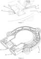
- FIG. 2presents a second sub-assembly (40) for connecting a position encoder, for example implementing Hall probes.
- Itconsists of a bundle of five conductive tracks (41 to 45) converging and supported by two insulating plates (46, 47).
- These tracks (41 to 45)are intended to be connected to an external circuit managing the power supply and the reading of the signals which pass through these tracks (41 to 45), in this case the signals from a position encoder, in the form for example of Hall probes.
- the five tracks (41 to 45)allow the connection of a ground (common), of a power supply (common) and of three probe signals (that is therefore indeed five connections necessary).
- each of the tracks (41 to 45)extends perpendicularly by a connection means, for example with one end (51 to 55) having a “needle eye” of the Press-Fit type (trade name).
- the two assemblies (4, 40)are overmolded to form a connector making it possible to provide both mechanical and electrical connection, by a system represented in picture 3 .
- the overmold (56)holds the two sub-assemblies (4, 40) together.
- One of the objects of the inventionis also to make possible different angular indexing of the two sub-assemblies (4, 40) according to the relative position of the output connectors -not shown- (for the supply of the coils of one hand and the management of Hall probes on the other hand).
- the molding (56)has projections (57), in the form of a non-limiting pin, intended to allow the indexing of the molded assembly on the coiled stator (60).
- the second sub-assembly (40)is secured at its inner end to a printed circuit (80) by a Press-fit type fixing or by welding of the ends (51 to 56).
- the printed circuit (80)also carries the Hall probes (81) intended to detect the position of the rotor of the motor (not shown).
- the stator (60) shown in figure 4consists of a stack of soft iron sheets (61) and having six wide radial teeth (62 to 67) intended to receive electric coils. Only one coil is shown here for clarity.
- the stator (60)also has spacer teeth that are narrower than the wide teeth (62 to 67). All the teeth extend radially with respect to a peripheral crown.
- This stator (60)conforms to that presented in the patent FR2899396 but is in no way limiting in the context of the present invention which is generally intended to allow the connection of all types of topologies of brushless motors whose teeth extend radially.
- Each wide tooth (62 to 67)carries a spool (75) which is installed on a spool body (76).
- These coil bodies (76)have on the one hand pockets (77) intended to allow the indexing of the sub-assemblies (4, 40) molded onto the wound stator (60) and on the other hand notches (78) intended to allow the electrical connection.
- these notches (78)are positioned the termination of an insulated electric wire which will be connected thanks to the self-stripping folded ends of the tracks (1, 2, 3).
- These notcheshave an insertion pocket opening onto a substantially rectangular cavity having two large longitudinal faces parallel to a median longitudinal plane. This median longitudinal plane and the two large faces are perpendicular to a radial axis.
- the pockets (77)can have various shapes and locations on the coil bodies (76) but must be of complementary shapes with the protrusions (57) present on the overmoulding (56).
- the pockets (77)can be chamfered to accept a tolerance in the assembly of the overmoulding (56) on the coil bodies (76).
- each wide toothcarries an electric coil wound around a coil body which has pockets and notches intended to accommodate the sub-assemblies (4, 40) for mechanical indexing and the electrical connection.
- the first connection subassembly (4)is applied to the front face of the stator (60) to ensure the mechanical connection of the assembly via the indexing of the overmoulding (56) with the pockets (62c to 67c), as represented in figure 6 .
- This tolerant indexingmakes it possible to correctly position the self-stripping folded ends (13a to 16a, 23a to 26a and 33a to 36a) of the first sub-assembly (4) and allow electrical connection inside the notches (78) of the bodies spool (76).
- FIG 7presents a detailed view of the figure 7 (according to the dotted frame of the figure 6 ) where one better appreciates the electrical connection which is made thanks to the folded end (13a) in the notch (78) permitted thanks to the mechanical indexing of the overmoulding (56) using the protrusion ( 57) which comes in the pocket (77).
- connection assembly after overmolding (84) of the assemblywhere the two sub-assemblies (4,40) allow the electrical connection of the motor coils and of the position sensor by the two female connectors of the motor (82) and sensor (83) complementary to the male connectors (not shown) in the application.
- the product thus formedallows safe electrical connections and with a minimum of parts in a limited axial space.
Landscapes
- Engineering & Computer Science (AREA)
- Power Engineering (AREA)
- Insulation, Fastening Of Motor, Generator Windings (AREA)
- Motor Or Generator Frames (AREA)
- Windings For Motors And Generators (AREA)
Description
Translated fromFrenchLa présente invention concerne le domaine des moteurs électromagnétiques sans balai et plus spécialement des moyens de connexion électriques de ces moteurs.The present invention relates to the field of brushless electromagnetic motors and more specifically to the electrical connection means of these motors.
L'invention se destine plus particulièrement à des moteurs présentant une grande compacité en épaisseur, c'est à dire lorsque le ratio du diamètre sur la hauteur doit être optimisé (typiquement section inférieure à 50 mm).The invention is intended more particularly for motors having a very compact thickness, that is to say when the ratio of the diameter to the height must be optimized (typically section less than 50 mm).
Les moteurs électromagnétiques sans balai présentent un ensemble de bobines d'excitation électrique généralement configurées pour réaliser une alimentation polyphasée. Dans le cas de moteurs triphasés, il y a donc 3X bobines à connecter, si X est le nombre de bobines par phase, reliées en série ou en parallèle, en configuration étoile ou triangle.Brushless electromagnetic motors have a set of electrical excitation coils generally configured to achieve polyphase power. In the case of three-phase motors, there are therefore 3X coils to be connected, if X is the number of coils per phase, connected in series or in parallel, in star or delta configuration.
On connaît dans l'art antérieur des solutions pour d'une part connecter les bobines entre elles et d'autre part pour sortir les 3 connexions nécessaires à l'alimentation des 3 phases. Par exemple, le
Des bobines de stator multi-phase montées dans un noyau de stator sont reliés par phase en reliant des anneaux aux extrémités de bobine des bobines de stator.Multi-phase stator coils mounted in a stator core are connected by phase by connecting rings to the coil ends of the stator coils.
Une barre de bus (BB) alimenté en énergie électrique à partir de l'extérieur est empilé sur les anneaux de liaison (CR) dans la direction axiale du moteur et est relié électriquement à des anneaux de liaison (CR).A bus bar (BB) supplied with electrical power from the outside is stacked on the connecting rings (CR) in the axial direction of the motor and is electrically connected to the connecting rings (CR).
Ce document de l'art antérieur ne divulgue pas de corps de bobine présentant deux encoches de connexion. Il ne présente pas de pistes de sortie coplanaires permettant de réaliser la connexion simple et directe avec les bobines.This prior art document does not disclose a coil body having two connection slots. It does not have coplanar output tracks allowing simple and direct connection with the coils.
Au paragraphe [0102] de ce document, on relève qu'il est prévu un « bus bar » qui est connecté sur des « connecting rings » qui elles même sont connectées aux bobines portées par des corps (qui ne semblent pas référencées dans D1 mais qui sont clairement visibles).In paragraph [0102] of this document, it is noted that a "bus bar" is provided which is connected to "connecting rings" which themselves are connected to the coils carried by the bodies (which do not seem to be referenced in D1 but which are clearly visible).
La présente invention concerne une solution de connectique où les pistes de sortie sont directement connectées aux bobines à travers le corps de bobine et ces pistes sont indexées par rapport à ces dits corps. Ainsi, ce document propose une solution qui présente au moins une pièce supplémentaire.The present invention relates to a connection solution where the output tracks are directly connected to the coils through the coil body and these tracks are indexed with respect to said bodies. Thus, this document proposes a solution which has at least one additional part.
Le corps de bobine n'est pas utilisé dans l'art antérieur puisque l'on utilise des « connectings rings » qui viennent crocheter les connexions bobine.The coil body is not used in the prior art since “connecting rings” are used which hook the coil connections.
Chacune des demandes de
Il nécessite donc un nombre important de pièces.It therefore requires a large number of parts.
De plus, l'extrémité de la piste de sortie n'est pas repliée de manière à réaliser une connexion axiale puisque c'est le fil qui sort axialement de manière à réaliser une connexion perpendiculairement (voir
Le brevet
Il n'y a donc aucune présence d'un corps de bobine qui présente une forme d'encoche complémentaire à celle de la piste de sortie. Il n'y a pas non plus, dans ce document, l'idée de réaliser des sorties coplanaires. La solution proposée n'apporte pas ses avantages de connectique simplifiée et nombre de pièces limité.There is therefore no presence of a coil body which has a notch shape complementary to that of the output track. Nor is there, in this document, the idea of making coplanar outputs. The proposed solution does not bring its advantages of simplified connections and limited number of parts.
Concernant le document
C'est l'inverse dans la présente, puisque le fil n'est pas dénudé dans les corps de bobine mais c'est la piste de sortie qui, par sa terminaison de type IDC intégrée réalise le dénudé du fil. Voir particulièrement la
Le brevet
Le brevet
Les solutions de l'art antérieur présentent un encombrement important, notamment dans la direction axiale, qui ne permet pas de réaliser des moteurs ultraplats de type « galette » et plus généralement qui augmentent le volume occupé par le moteur.The solutions of the prior art have a large bulk, in particular in the axial direction, which does not make it possible to produce ultra-flat motors of the “pancake” type and more generally which increase the volume occupied by the motor.
Lorsque l'encombrement est contraint par un espace disponible restreint, l'espace occupé par le connecteur réduit le volume disponible pour le rotor et le stator, et donc au détriment de la puissance et des qualités électromécaniques du moteur ou de l'actionneur.When the bulk is constrained by a restricted available space, the space occupied by the connector reduces the volume available for the rotor and the stator, and therefore to the detriment of the power and the electromechanical qualities of the motor or of the actuator.
La présente invention a pour but de répondre aux problèmes soulevés ci-dessus en proposant une solution de connectique avantageuse permettant de ramener les 3 phases électriques d'un moteur à X bobines par phase, connectées en série ou parallèle et en triangle ou étoile, à un connecteur ayant 3 cosses, avec un nombre limité de pièces et un encombrement très réduit, tant dans la direction axiale que dans la dimension transversale.The purpose of the present invention is to respond to the problems raised above by proposing an advantageous connection solution making it possible to bring the 3 electrical phases from a motor with X coils per phase, connected in series or parallel and in delta or star, to a connector with 3 lugs, with a limited number of parts and a very reduced overall size, both in the axial direction and in the transverse dimension .
A cet effet, l'invention concerne selon son acception la plus générale un système comprenant d'une part un moteur électrique sans balai et d'autre part un ensemble de connexion complémentaire, ledit moteur électromagnétique sans balai comprenant un ensemble statorique bobiné à P phases électriques et X bobines (75) par phase, chaque bobine (75) étant portée par un corps (76) muni de deux encoches (78) de connexion, ledit ensemble de connections étant constitué par un premier sous-ensemble (4) formé de W pistes (1,2, 3) découpées dans une seule feuille conductrice et étant essentiellement coplanaire, - hormis éventuellement les prolongements de liaison (11, 21, 31) - présentant des prolongements de liaison (11, 21, 31) parallèles entre eux et constituant les pattes de raccordement permettant d'établir un contact électrique avec un connecteur pour l'alimentation des bobines (75), W étant un nombre entier compris entre P et P+1, chacune desdites W pistes (1,2,3) se terminant par au moins une extrémité repliée (13a,14a,15a,16a, 23a, 24a, 25a, 26a, 33a, 34a, 35a, 36a) perpendiculairement au plan desdites pistes (1,2,3), la forme de ladite extrémité repliées (13a, 14a, 15a,16a) étant complémentaire à la forme de l'encoche (78) de connexion, lesdites pistes (1, 2, 3) étant réunies par une matière plastique isolante.To this end, the invention relates, in its most general sense, to a system comprising on the one hand a brushless electric motor and on the other hand a complementary connection assembly, said brushless electromagnetic motor comprising a wound stator assembly with P phases and X coils (75) per phase, each coil (75) being carried by a body (76) provided with two notches (78) for connection, said set of connections being constituted by a first sub-assembly (4) formed of W tracks (1,2, 3) cut from a single conductive sheet and being essentially coplanar, - except possibly for the connecting extensions (11, 21, 31) - having connecting extensions (11, 21, 31) parallel to each other and constituting the connecting lugs making it possible to establish electrical contact with a connector for supplying the coils (75), W being an integer between P and P+1, each of the said W tracks (1,2,3) ending with at least a folded end (13a, 14a, 15a, 16a, 23a, 24a, 25a, 26a, 33a, 34a, 35a, 36a) perpendicular to the plane of said tracks (1,2,3), the shape of said folded end (13a, 14a, 15a, 16a) being complementary to the shape of the notch (78) for connection, said tracks (1, 2, 3) being joined by an insulating plastic material.
Avantageusement, les dites pistes sont maintenues par le surmoulage d'une matière plastique isolante.Advantageously, said tracks are maintained by the overmolding of an insulating plastic material.
L'invention a aussi pour but de proposer une solution de connexion d'un ensemble de Y signaux (par exemple ceux de sondes de Hall) appartenant à un codeur servant à détecter la position au rotor dudit moteur depuis un circuit imprimé vers ce même connecteur. À cet effet, le codeur se présente avantageusement sous la forme d'au moins une piste circulaire aimantée liée au rotor et présentant des alternances de pôles magnétiques Nord-Sud associée à au moins deux sondes de Hall, positionnées sur un circuit imprimé au voisinage axial direct de la piste aimantée et détectant l'évolution de l'induction magnétique générée par la piste aimantée. La gestion électrique (alimentation et lecture des signaux) des sondes de Hall est réalisée par un ensemble de Y fiches qui partent du circuit imprimé et sont sorties, hors du moteur et latéralement, vers un connecteur.The invention also aims to provide a solution for connecting a set of Y signals (for example those of Hall probes) belonging to an encoder used to detect the position of the rotor of said motor from a printed circuit to this same connector . To this end, the encoder is advantageously in the form of at least one magnetic circular track connected to the rotor and having alternating North-South magnetic poles associated with at least two Hall probes, positioned on a printed circuit in the axial vicinity. directly from the magnetic track and detecting the evolution of the magnetic induction generated by the magnetic track. The electrical management (power supply and signal reading) of the Hall probes is carried out by a set of Y plugs which start from the printed circuit and are output, outside the motor and laterally, towards a connector.
Selon ce mode de réalisation particulier, l'ensemble de connexion selon l'invention comporte en outre un sous-ensemble de pistes de connexion pour le raccordement à au moins un capteur de position.According to this particular embodiment, the connection assembly according to the invention further comprises a subset of connection tracks for connection to at least one position sensor.
Avantageusement, les pistes extérieures présentent des décrochements pour permettre l'optimisation du découpage dans une seule feuille métallique.Advantageously, the outer tracks have recesses to allow the optimization of the cutting in a single metal sheet.
Selon un mode de mise en oeuvre préféré, ledit sous-ensemble de pistes de connexion pour le raccordement à au moins un capteur de position est co-moulé lors du surmoulage des pistes de connexion des bobines.According to a preferred embodiment, said subset of connection tracks for connection to at least one position sensor is co-molded during the overmolding of the connection tracks of the coils.
Selon un mode de réalisation particulier, les surfaces des encoches de connexion perpendiculaires à la direction d'insertion de l'extrémité repliée présentent des poches complémentaires à des excroissances présentes sur le surmoulage, entourant l'extrémité repliée correspondante.According to a particular embodiment, the surfaces of the connection notches perpendicular to the direction of insertion of the folded end have pockets complementary to the protrusions present on the overmoulding, surrounding the corresponding folded end.
L'invention sera mieux comprise à la lecture de la description qui suit, faisant référence aux dessins annexés où :
- la
figure 1 représente un premier sous-ensemble de connexion des bobines, pour former un connecteur conforme à la présente invention, - la
figure 2 représente un deuxième sous-ensemble de connexion des capteurs, pour former un connecteur conforme à la présente invention, - la
figure 3 représente un connecteur conforme à la présente invention, - la
figure 4 représente une vue isolée de l'ensemble statorique avec une seule bobine, - la
figure 5 représente une vue isolée de l'ensemble statorique complet bobiné, - la
figure 6 présente une vue du stator et de l'ensemble de connexion, - la
figure 7 présente une vue de détail de lafigure 6 , - la
figure 8 présente l'ensemble de connexion et moteur surmoulé.
- there
figure 1 represents a first coil connection subassembly, to form a connector according to the present invention, - there
figure 2 represents a second sensor connection subassembly, to form a connector according to the present invention, - there
picture 3 - there
figure 4 represents an isolated view of the stator assembly with a single coil, - there
figure 5 represents an isolated view of the complete wound stator assembly, - there
figure 6 presents a view of the stator and the connection assembly, - there
figure 7 presents a detailed view of thefigure 6 , - there
figure 8 shows the overmolded connection and motor assembly.
La
Le premier sous-ensemble (4) est formé de trois pistes (1 à 3) découpés dans une feuille d'un matériau conducteur, de préférence amagnétique, tel que du laiton, par exemple un alliage Cuivre-Zinc de type CuZn30 qui se compose de 70% de cuivre et de 30% de zinc.The first sub-assembly (4) is formed of three tracks (1 to 3) cut from a sheet of conductive material, preferably non-magnetic, such as brass, for example a Copper-Zinc alloy of the CuZn30 type which consists 70% copper and 30% zinc.
La découpe peut être réalisée par estampage, par jet d'eau pure ou chargée de silice, par laser ou tout autre technique connue de l'homme du métier.The cutting can be carried out by stamping, by jet of pure water or charged with silica, by laser or any other technique known to those skilled in the art.
Les trois pistes (1 à 3) sont essentiellement coplanaires (hormis éventuellement les prolongements de liaison (11, 21, 31)), et présentent des prolongements de liaison parallèles entre eux (11, 21, 31) s'étendant parallèlement à un prolongement de liaison médian (31). Ces prolongements de liaison (11, 21, 31) constituent les pattes de raccordement permettant d'établir un contact électrique avec un connecteur pour l'alimentation des bobines (non montrés ici).The three tracks (1 to 3) are essentially coplanar (apart possibly from the connecting extensions (11, 21, 31)), and have connecting extensions parallel to each other (11, 21, 31) extending parallel to an extension median connection (31). These connecting extensions (11, 21, 31) constitute the connecting lugs making it possible to establish electrical contact with a connector for supplying the coils (not shown here).
Chaque piste (1 à 3) est reliée à quatre bobines pour former deux à deux une phase d'alimentation électrique, selon une configuration connue dans l'état de la technique.Each track (1 to 3) is connected to four coils to form an electrical power supply phase in pairs, according to a configuration known in the state of the art.
La première piste (1) présente une partie arquée (12) s'étendant sur environ 220°, terminée par un prolongement de liaison (11). La partie arquée (12) est prolongée dans sa partie intérieure par quatre épanouissements radiaux (13 à 16) dirigés vers le centre de courbure de la partie arquée (12).The first track (1) has an arcuate part (12) extending over approximately 220°, terminated by a connecting extension (11). The arcuate part (12) is extended in its inner part by four radial expansions (13 to 16) directed towards the center of curvature of the arcuate part (12).
Chacun de ces épanouissements radiaux (13 à 16) se termine par une extrémité auto-dénudant repliée à 90° (13a à 16a) permettant d'assurer la connexion sur les fils des bobines par une connexion de type auto-dénudant (IDC, en anglais, pourInsulation Displacement Contact).Each of these radial expansions (13 to 16) ends with a self-stripping end bent at 90° (13a to 16a) making it possible to ensure the connection to the wires of the coils by a connection of the self-stripping type (IDC, in English, forInsulation Displacement Contact ).
Le positionnement angulaire de ces épanouissements radiaux (13 à 16) et des extrémités repliées correspondantes (13a à 16a) est déterminé en fonction de la position des fils de raccordement des bobines du stator.The angular positioning of these radial expansions (13 to 16) and of the corresponding folded ends (13a to 16a) is determined according to the position of the connecting wires of the stator coils.
La partie arquée (12) présente une épaisseur radiale sensiblement constante. Toutefois, elle présente des décrochements (17 à 19) afin de permettre de découper dans une même feuille les trois pistes (1, 2, 3) en réduisant la perte de matière. La profondeur de ces décrochements (17 à 19) et leur extension angulaire est fixé afin de permettre le découpage de des épanouissements radiaux des pistes complémentaires (2, 3).The arcuate part (12) has a substantially constant radial thickness. However, it has recesses (17 to 19) in order to allow the three tracks (1, 2, 3) to be cut from the same sheet while reducing the loss of material. The depth of these recesses (17 to 19) and their angular extension is fixed in order to allow the cutting of the radial expansions of the complementary tracks (2, 3).
La deuxième piste (2) présente une partie arquée (22) s'étendant sur environ 220°, terminée par un prolongement de liaison (21). La partie arquée (22) est prolongée par quatre épanouissements radiaux (23 à 26) dirigés vers le centre de courbure de la partie arquée (22). La partie arquée (22) est disposée de manière sensiblement symétrique à la première partie arquée (12), par rapport à un axe médian passant par le prolongement de liaison centrale (31).The second track (2) has an arcuate part (22) extending over approximately 220°, terminated by a connecting extension (21). The arcuate part (22) is extended by four radial expansions (23 to 26) directed towards the center of curvature of the arcuate part (22). The arcuate part (22) is disposed substantially symmetrically to the first arcuate part (12), with respect to a median axis passing through the central link extension (31).
Chacun de ces épanouissements radiaux (23 à 26) se termine par une extrémité auto-dénudant repliée à 90° (23a à 26a) permettant d'assurer la connexion sur les fils des bobines par une connexion de type auto-dénudant (IDC, en anglais, pourInsulation Displacement Contact). Chacune des extrémités présentent un plan médian perpendiculaire à un axe radial passant par le centre de l'épanouissement.Each of these radial expansions (23 to 26) ends with a self-stripping end bent at 90° (23a to 26a) making it possible to ensure the connection to the wires of the coils by a self-stripping type connection (IDC, in English, forInsulation Displacement Contact ). Each of the ends has a median plane perpendicular to a radial axis passing through the center of the expansion.
La partie arquée (22) présente un premier tronçon (22a) présentant le même rayon que la partie arquée (12) de la première piste (1). Ce premier tronçon (22a) s'étend sur environ 120° et se prolonge ensuite par un deuxième tronçon (22b) s'étendant sur environ 100°, avec un rayon inférieur. Les deux tronçons (22a, 22b) sont reliés par un tronçon radial (22c) .The arcuate part (22) has a first section (22a) having the same radius as the arcuate part (12) of the first track (1). This first section (22a) extends over approximately 120° and is then extended by a second section (22b) extending over approximately 100°, with a smaller radius. The two sections (22a, 22b) are connected by a radial section (22c).
La partie arquée (22) présente une épaisseur radiale sensiblement constante. Toutefois, elle présente des décrochements (27, 28) afin de permettre de découper dans une même feuille les trois pistes, en réduisant la perte de matière. La profondeur de ces décrochements (27, 28) et leur extension angulaire est fixé afin de permettre le découpage de des épanouissements radiaux des pistes complémentaires (2, 3).The arcuate part (22) has a substantially constant radial thickness. However, it has recesses (27, 28) in order to allow the three tracks to be cut from the same sheet, reducing the loss of material. The depth of these recesses (27, 28) and their angular extension is fixed in order to allow the cutting of the radial expansions of the complementary tracks (2, 3).
La troisième piste (3) présente une partie arquée (32) s'étendant sur environ 220°, terminée par un prolongement de liaison (31). La partie arquée (32) présente un rayon sensiblement identique au rayon du deuxième tronçon (22b) de la deuxième piste (2).The third track (3) has an arcuate part (32) extending over approximately 220°, terminated by a connecting extension (31). The arcuate part (32) has a radius substantially identical to the radius of the second section (22b) of the second track (2).
La partie arquée (32) est prolongée par quatre épanouissements radiaux (33 à 36) dirigés en direction opposée au centre de la courbure de la partie arquée (32).The arcuate part (32) is extended by four radial expansions (33 to 36) directed in the opposite direction to the center of the curvature of the arcuate part (32).
Chacun de ces épanouissements radiaux (33 à 36) se termine par une extrémité auto-dénudant repliée à 90° (33a à 36a) permettant d'assurer la connexion sur les fils des bobines par une connexion de type auto-dénudant (IDC, en anglais, pourInsulation Displacement Contact).Each of these radial expansions (33 to 36) ends with a self-stripping end bent at 90° (33a to 36a) making it possible to ensure the connection to the wires of the coils by a self-stripping type connection (IDC, in English, forInsulation Displacement Contact ).
Les pistes sont ainsi découpées dans une seule feuille comme en témoigne les ponts (9, 10) visibles sur cette figure mais qui sont coupés après réalisation du sous-ensemble (4) pour isoler les pistes les unes des autres.The tracks are thus cut out from a single sheet as evidenced by the bridges (9, 10) visible in this figure but which are cut after completion of the sub-assembly (4) to isolate the tracks from each other.
La
Il est constitué par un faisceau de cinq pistes conductrices (41 à 45) convergeant et supportés par deux platines isolantes (46, 47).It consists of a bundle of five conductive tracks (41 to 45) converging and supported by two insulating plates (46, 47).
Ces pistes (41 à 45) sont destinées à être connectées à un circuit extérieur gérant l'alimentation et la lecture des signaux qui passent par ces pistes (41 à 45), en l'occurrence les signaux d'un codeur de la position, sous forme par exemple de sondes de Hall. Par exemple, avec trois sondes de Hall, les cinq pistes (41 à 45) permettent la connexion d'une masse (commune), d'une alimentation (commune) et de trois signaux de sondes (soit donc bien cinq connexion nécessaires).These tracks (41 to 45) are intended to be connected to an external circuit managing the power supply and the reading of the signals which pass through these tracks (41 to 45), in this case the signals from a position encoder, in the form for example of Hall probes. For example, with three Hall probes, the five tracks (41 to 45) allow the connection of a ground (common), of a power supply (common) and of three probe signals (that is therefore indeed five connections necessary).
L'extrémité de chacune des pistes (41 à 45) s'étend perpendiculairement par un moyen de connexion, par exemple avec une extrémité (51 à 55) présentant un « chas d'aiguille » de type Press-Fit (nom commercial).The end of each of the tracks (41 to 45) extends perpendicularly by a connection means, for example with one end (51 to 55) having a “needle eye” of the Press-Fit type (trade name).
Les deux ensembles (4, 40) sont surmoulés pour former un connecteur permettant d'assurer la liaison à la fois mécanique et électrique, par un système représenté en
Le surmoulage (56) présente des excroissances (57), sous une forme de pion non limitative, destinées à permettre l'indexation de l'ensemble surmoulé sur le stator (60) bobiné. Le deuxième sous-ensemble (40) est solidaire sur son extrémité intérieur à un circuit imprimé (80) par une fixation de type Press-fit ou par soudure des extrémités (51 à 56). Le circuit imprimé (80) porte par ailleurs les sondes de Hall (81) destinées à détecter la position du rotor du moteur (non montré).The molding (56) has projections (57), in the form of a non-limiting pin, intended to allow the indexing of the molded assembly on the coiled stator (60). The second sub-assembly (40) is secured at its inner end to a printed circuit (80) by a Press-fit type fixing or by welding of the ends (51 to 56). The printed circuit (80) also carries the Hall probes (81) intended to detect the position of the rotor of the motor (not shown).
Le stator (60) représenté en
Chaque dent large (62 à 67) porte une bobine (75) qui est installée sur un corps de bobine (76). Ces corps de bobines (76) présentent d'une part des poches (77) destinées à permettre l'indexation des sous-ensembles (4, 40) surmoulés sur le stator (60) bobiné et d'autre part des encoches (78) destinées à permettre la connexion électrique. Dans ces encoches (78) sont positionnés la terminaison d'un fil électrique isolé qui sera connecté grâce aux extrémités repliées auto-dénudant des pistes (1, 2, 3). Ces encoches présentent une poche d'introduction s'ouvrant sur une cavité sensiblement rectangulaire présentant deux grandes faces longitudinales parallèles à un plan longitudinal médian. Ce plan longitudinal médian et les deux grandes faces sont perpendiculaires à un axe radial.Each wide tooth (62 to 67) carries a spool (75) which is installed on a spool body (76). These coil bodies (76) have on the one hand pockets (77) intended to allow the indexing of the sub-assemblies (4, 40) molded onto the wound stator (60) and on the other hand notches (78) intended to allow the electrical connection. In these notches (78) are positioned the termination of an insulated electric wire which will be connected thanks to the self-stripping folded ends of the tracks (1, 2, 3). These notches have an insertion pocket opening onto a substantially rectangular cavity having two large longitudinal faces parallel to a median longitudinal plane. This median longitudinal plane and the two large faces are perpendicular to a radial axis.
Les poches (77) peuvent présenter des formes et localisation diverses sur les corps de bobines (76) mais doivent être de formes complémentaires avec les excroissances (57) présentes sur le surmoulage (56). Avantageusement les poches (77) peuvent être chanfreinées pour accepter une tolérance dans le montage du surmoulage (56) sur les corps de bobine (76).The pockets (77) can have various shapes and locations on the coil bodies (76) but must be of complementary shapes with the protrusions (57) present on the overmoulding (56). Advantageously the pockets (77) can be chamfered to accept a tolerance in the assembly of the overmoulding (56) on the coil bodies (76).
La
Le premier sous-ensemble de connexion (4) est appliqué sur la face frontale du stator (60) pour assurer la connexion mécanique de l'ensemble via l'indexation du surmoulage (56) avec les poches (62c à 67c), comme représenté en
La
La
Le produit ainsi formé permet des connexions électriques sûres et avec un minimum de pièces dans un encombrement axial limité.The product thus formed allows safe electrical connections and with a minimum of parts in a limited axial space.
Claims (7)
- System, comprising a brushless electric motor and a complementary connection assembly, said brushless electromagnetic motor comprising a stator assembly (60) wound with P electrical phases and X coils (75) per phase, each coil (75) being carried by a body (76) provided with two connection notches (78),characterized in that said connection assembly is constituted by a first sub-assembly (4) formed by W tracks (1, 2, 3) which are cut from a single conductive sheet and are substantially coplanar, optionally apart from the connecting extensions (11, 21, 31), having connecting extensions (11, 21, 31) which are parallel to one another and constitute the attachment lugs making it possible for electrical contact to be made with a connector for powering the coils (75), W being an integer between P and P+1, each of said W tracks (1, 2, 3) terminating in at least one folded end (13a, 14a, 15a, 16a, 23a, 24a, 25a, 26a, 33a, 34a, 35a, 36a) perpendicularly to the plane of said tracks (1, 2, 3), the shape of said folded end (13a, 14a, 15a, 16a) being complementary to the shape of the connection notch (78), said tracks (1, 2, 3) being joined by an insulating plastics material.
- System according to claim 1,characterized in that said tracks (1, 2, 3) are held by the molding of an insulating plastics material.
- System according to claim 2,characterized in that it further comprises a second sub-assembly (40) of conductive tracks (41, 42, 43, 44, 45) for connection to at least one position sensor.
- System according to the preceding claim,characterized in that the second sub-assembly (40) is co-molded during the molding of the tracks (1, 2, 3) for connecting the coils.
- System according to any of claims 2 to 4,characterized in that the tracks (1, 2, 3) have a circular shape andin that there are recessed parts (17, 18, 19, 27, 28) on the outer tracks to allow cutting in a single sheet.
- System according to the preceding claim,characterized in that the molding (56) of the connection tracks (1, 2, 3) has projections (57).
- System according to the preceding claim,characterized in that the surfaces of the notches (78) for connection perpendicular to the direction of insertion of the folded end (13a, 14a, 15a, 16a) have pockets (77) which are complementary to the projections (57) of the molding (56) surrounding said corresponding folded end (13a, 14a, 15a, 16a).
Applications Claiming Priority (2)
| Application Number | Priority Date | Filing Date | Title |
|---|---|---|---|
| FR1259035AFR2996072B1 (en) | 2012-09-26 | 2012-09-26 | ELECTRICAL CONNECTION ASSEMBLY FOR BRUSHLESS MOTOR |
| PCT/FR2013/051971WO2014049218A2 (en) | 2012-09-26 | 2013-08-27 | Electrical connection assembly for brushless motor and system comprising such an assembly |
Publications (2)
| Publication Number | Publication Date |
|---|---|
| EP2901542A2 EP2901542A2 (en) | 2015-08-05 |
| EP2901542B1true EP2901542B1 (en) | 2023-03-29 |
Family
ID=47505060
Family Applications (1)
| Application Number | Title | Priority Date | Filing Date |
|---|---|---|---|
| EP13795814.6AActiveEP2901542B1 (en) | 2012-09-26 | 2013-08-27 | Electric connection assembly for a brushless motor and system comprising such an assembly |
Country Status (5)
| Country | Link |
|---|---|
| US (1) | US9812918B2 (en) |
| EP (1) | EP2901542B1 (en) |
| JP (1) | JP6416767B2 (en) |
| FR (1) | FR2996072B1 (en) |
| WO (1) | WO2014049218A2 (en) |
Families Citing this family (23)
| Publication number | Priority date | Publication date | Assignee | Title |
|---|---|---|---|---|
| JP6135982B2 (en)* | 2013-01-17 | 2017-05-31 | 日本電産株式会社 | motor |
| JP6185826B2 (en)* | 2013-11-27 | 2017-08-23 | タイコエレクトロニクスジャパン合同会社 | Motor connector and motor connector assembly |
| JP2015104284A (en)* | 2013-11-27 | 2015-06-04 | タイコエレクトロニクスジャパン合同会社 | Stator frame for motor |
| DE102014220201A1 (en)* | 2014-10-06 | 2016-04-07 | Bühler Motor GmbH | Electronically commutated DC motor, in particular for an oil pump |
| FR3030147B1 (en)* | 2014-12-11 | 2018-03-16 | Mmt Sa | ACTUATOR WITH STATORIC AND ROTORIC MODULES COATED |
| US10348158B2 (en)* | 2015-02-04 | 2019-07-09 | Makita Corporation | Power tool |
| TWI573372B (en)* | 2015-07-08 | 2017-03-01 | Motor stator structure | |
| US10910899B2 (en)* | 2016-05-11 | 2021-02-02 | Hitachi Automotive Systems, Ltd. | Rotary electric machine |
| ES2985905T3 (en) | 2016-11-22 | 2024-11-07 | Lts Device Tech Ltd | Apparatus for delivering a therapeutic substance |
| EP3580832A4 (en) | 2017-02-13 | 2021-03-03 | Milwaukee Electric Tool Corporation | Brushless direct current motor for power tools |
| US11081870B2 (en)* | 2017-03-03 | 2021-08-03 | Nidec Corporation | Bus bar unit, motor, electric power steering device |
| JP7176510B2 (en)* | 2017-03-31 | 2022-11-22 | 日本電産株式会社 | Busbar unit and motor |
| JP6305604B1 (en)* | 2017-05-12 | 2018-04-04 | 三菱電機株式会社 | Rotating electric machine |
| WO2019028048A1 (en)* | 2017-07-31 | 2019-02-07 | Pentair Flow Technologies, Llc | Ring-style terminal block and submersible pump with ring-style terminal block |
| FR3071112B1 (en) | 2017-09-12 | 2021-10-22 | Mmt ag | CONNECTION SYSTEM FOR ELECTRIC MACHINE. |
| CN108233632A (en)* | 2018-03-12 | 2018-06-29 | 何宇峰 | A plug-in signal generator |
| ES2986346T3 (en) | 2018-10-05 | 2024-11-11 | Lts Device Tech Ltd | Activation sequence |
| DE102019202911A1 (en)* | 2019-03-05 | 2020-09-10 | Zf Friedrichshafen Ag | Interconnection arrangement and stator for an electrical machine |
| FR3104340A1 (en) | 2019-12-10 | 2021-06-11 | Sonceboz Mechatronics Boncourt Sa | ELECTRIC MOTOR |
| FR3141029A1 (en)* | 2022-10-18 | 2024-04-19 | Valeo Systemes Thermiques | Connector for a printed circuit forming a heat sink and configured to allow electrical and mechanical connection. |
| FR3146718A1 (en)* | 2023-03-14 | 2024-09-20 | Faurecia Sièges d'Automobile | Actuator |
| FR3149151A1 (en)* | 2023-05-26 | 2024-11-29 | Valeo Systemes D'essuyage | Coil and stator for electric machine, electric machine and associated assembly method |
| CN116742883A (en)* | 2023-06-05 | 2023-09-12 | 鸣志电器(太仓)有限公司 | A motor with outlet wires in the same direction |
Citations (1)
| Publication number | Priority date | Publication date | Assignee | Title |
|---|---|---|---|---|
| US20100052461A1 (en)* | 2006-11-30 | 2010-03-04 | Kei Sasaki | Insulating member and stator |
Family Cites Families (40)
| Publication number | Priority date | Publication date | Assignee | Title |
|---|---|---|---|---|
| US4287446A (en) | 1979-06-27 | 1981-09-01 | Amp Incorporated | Stator for stepper motor |
| US4689023A (en) | 1985-08-27 | 1987-08-25 | The Superior Electric Company | Programmable electrical connector |
| US5770902A (en) | 1995-11-02 | 1998-06-23 | Globe Motors | Motor termination board |
| US5932942A (en) | 1997-12-16 | 1999-08-03 | Reliance Electric Industrial Company | DC motor drive with improved thermal characteristics |
| JP4224649B2 (en) | 1999-01-29 | 2009-02-18 | 株式会社 サーモセッタ | Insulated housing for three-phase AC motor |
| JP3696080B2 (en) | 2000-12-05 | 2005-09-14 | 三菱電機株式会社 | Rotating electric machine |
| DE10130117A1 (en)* | 2001-06-22 | 2003-01-30 | Minebea Co Ltd | Housing cover for an electric motor, in particular for an electronically commutated direct current motor |
| DE10152006B4 (en)* | 2001-10-22 | 2011-06-01 | Zf Sachs Ag | Stator for an electric machine |
| JP3733312B2 (en)* | 2001-10-26 | 2006-01-11 | 住友電装株式会社 | Manufacturing method of bus bar used for concentrated power distribution member of thin brushless motor for vehicle |
| JP2003294488A (en) | 2002-04-02 | 2003-10-15 | Tamagawa Seiki Co Ltd | Stator structure for resolver |
| JP3613262B2 (en)* | 2002-04-26 | 2005-01-26 | 三菱電機株式会社 | Rotating electric machine and manufacturing method thereof |
| JP3894853B2 (en) | 2002-07-11 | 2007-03-22 | 株式会社日本自動車部品総合研究所 | Rotating machine |
| JP3681366B2 (en) | 2002-08-21 | 2005-08-10 | 日立電線株式会社 | Distribution parts and manufacturing method thereof |
| DE10261611A1 (en) | 2002-12-27 | 2004-07-08 | Robert Bosch Gmbh | Connection element for a winding of an electrical machine |
| JP3903922B2 (en)* | 2003-01-27 | 2007-04-11 | 株式会社デンソー | Concentrated winding stator coil of rotating electric machine |
| JP4350972B2 (en)* | 2003-05-08 | 2009-10-28 | ヤマハモーターエレクトロニクス株式会社 | Rotating machine armature |
| JP4350974B2 (en) | 2003-05-22 | 2009-10-28 | ヤマハモーターエレクトロニクス株式会社 | Armature terminal |
| WO2004114502A1 (en) | 2003-06-20 | 2004-12-29 | Siemens Aktiengesellschaft | Electric machine comprising a circuit support |
| DE10347483A1 (en)* | 2003-09-30 | 2005-05-12 | Bosch Gmbh Robert | Electric machine |
| DE50313509D1 (en) | 2003-10-22 | 2011-04-14 | Brose Fahrzeugteile | Interconnection unit for a stator of an electric motor |
| JP4425045B2 (en) | 2004-04-14 | 2010-03-03 | 三菱電機株式会社 | Resolver |
| JP4662200B2 (en) | 2004-09-29 | 2011-03-30 | 日本電産株式会社 | Motor and busbar |
| US8035263B2 (en) | 2004-11-10 | 2011-10-11 | Ebm-Papst St. Georgen Gmbh & Co. Kg | Electric motor |
| JP4783012B2 (en) | 2004-12-28 | 2011-09-28 | 日立オートモティブシステムズ株式会社 | Electric power steering motor and manufacturing method thereof |
| US20060232143A1 (en) | 2005-04-15 | 2006-10-19 | Delaware Capital Formation | Over molded stator |
| ES2294637T5 (en) | 2005-05-23 | 2013-09-05 | Ebm Papst Mulfingen Gmbh & Co | Stator for an electric motor |
| JP4654103B2 (en) | 2005-10-05 | 2011-03-16 | 矢崎総業株式会社 | Power distribution member |
| EP1811634B1 (en)* | 2006-01-24 | 2012-04-25 | Alstom Technology Ltd | Connection arrangement for the stator winding of a turbo machine having two or more parallel circuits |
| FR2899396B1 (en) | 2006-03-30 | 2008-07-04 | Moving Magnet Tech Mmt | POLYPHASE ELECTRIC MOTOR, IN PARTICULAR FOR DRIVING PUMPS OR FANS |
| JP5041200B2 (en)* | 2006-03-30 | 2012-10-03 | アイシン精機株式会社 | Stator core and its split core |
| JP4692386B2 (en)* | 2006-05-22 | 2011-06-01 | トヨタ自動車株式会社 | Rotating machine with terminal module |
| JP5028869B2 (en)* | 2006-06-05 | 2012-09-19 | 日本電産株式会社 | Brushless motor |
| JP2008029138A (en)* | 2006-07-21 | 2008-02-07 | Showa Corp | Terminal for rotating electrical machine |
| FR2923951B1 (en)* | 2007-11-19 | 2009-11-27 | Sonceboz Automotive Sa | ELECTRICAL CONNECTION ASSEMBLY FOR MOTOR WITHOUT BRUSH. |
| DE102009004645A1 (en) | 2008-02-12 | 2009-08-13 | Ebm-Papst St. Georgen Gmbh & Co. Kg | Electronically commutated motor |
| US8154163B2 (en)* | 2008-04-15 | 2012-04-10 | Honda Motor Co., Ltd. | Electric power collection/distribution ring of rotary electric machine |
| JP2010154701A (en)* | 2008-12-26 | 2010-07-08 | Showa Corp | Terminal for rotating electrical machine |
| JP5132631B2 (en)* | 2009-05-25 | 2013-01-30 | 三菱電機株式会社 | Motor stator, motor, air conditioner, and motor manufacturing method |
| IT1397784B1 (en)* | 2010-01-15 | 2013-01-24 | Gate Srl | MANIFOLD FOR THE STATOR OF A BRUSHLESS MOTOR CURRENT CONTINUES WITH PERMANENT MAGNETS |
| JP2012110188A (en)* | 2010-11-19 | 2012-06-07 | Nippon Densan Corp | Intermediate connection member, stator, and motor |
- 2012
- 2012-09-26FRFR1259035Apatent/FR2996072B1/enactiveActive
- 2013
- 2013-08-27JPJP2015533658Apatent/JP6416767B2/enactiveActive
- 2013-08-27WOPCT/FR2013/051971patent/WO2014049218A2/enactiveApplication Filing
- 2013-08-27USUS14/431,124patent/US9812918B2/enactiveActive
- 2013-08-27EPEP13795814.6Apatent/EP2901542B1/enactiveActive
Patent Citations (1)
| Publication number | Priority date | Publication date | Assignee | Title |
|---|---|---|---|---|
| US20100052461A1 (en)* | 2006-11-30 | 2010-03-04 | Kei Sasaki | Insulating member and stator |
Also Published As
| Publication number | Publication date |
|---|---|
| WO2014049218A2 (en) | 2014-04-03 |
| JP2015530864A (en) | 2015-10-15 |
| WO2014049218A3 (en) | 2014-12-31 |
| FR2996072B1 (en) | 2016-07-29 |
| US9812918B2 (en) | 2017-11-07 |
| US20150249375A1 (en) | 2015-09-03 |
| JP6416767B2 (en) | 2018-10-31 |
| FR2996072A1 (en) | 2014-03-28 |
| EP2901542A2 (en) | 2015-08-05 |
Similar Documents
| Publication | Publication Date | Title |
|---|---|---|
| EP2901542B1 (en) | Electric connection assembly for a brushless motor and system comprising such an assembly | |
| EP2212985B1 (en) | Electrical connector assembly for a brushless motor | |
| EP2789076B1 (en) | Device for guiding a set of electrical wires for electric motor rotor | |
| EP3682531B1 (en) | Connection system for an electrical machine | |
| FR2934930A1 (en) | MOTOR FOR AN ELECTRICALLY ASSISTED STEERING DEVICE | |
| EP3057201B1 (en) | Electric motor rotor and electric motor associated | |
| EP3005535B1 (en) | Electric machine furnished with a system for guiding at least one connection wire of a measurement probe and corresponding guiding system | |
| EP3231071A1 (en) | Actuator with coated stator and rotor modules | |
| FR2932318A1 (en) | BRUSH HOLDER TIP AND ITS APPLICATION TO THE PRODUCTION OF A STARTER FOR A MOTOR VEHICLE | |
| CH699082B1 (en) | electric motor with connector. | |
| EP3718197A1 (en) | Electrical phase connector for rotary electric machine stator | |
| WO2016012329A1 (en) | Electric stepper motor | |
| JP6366849B2 (en) | Rotating electric machine and method of manufacturing rotating electric machine | |
| WO2019011759A1 (en) | Rotary electric machine provided with a stator with hairpin winding | |
| FR2995472A1 (en) | Interconnector for stator of e.g. polyphase electric machine, in electric car, has housings distributed regularly, where housings are intended to receive connections formed by legs, and ends of coil welded to legs for electric insulation | |
| WO2020174166A1 (en) | Connection device for stator | |
| WO2019180240A1 (en) | Electric connection device for a rotary electric machine | |
| WO2014102097A1 (en) | Electrical connector and electrical machine comprising such a connector | |
| EP4073908A1 (en) | Electric motor comprising a housing with a stator overmoulding and connection assemblies | |
| FR3059847A1 (en) | ROTATING ELECTRIC MACHINE HAVING LOW ACOUSTIC NOISE OF ELECTROMAGNETIC ORIGIN | |
| EP4078780A1 (en) | Stator comprising an interconnector | |
| FR3128329A1 (en) | Wound rotor for electric motor arranged to facilitate its assembly | |
| FR3019405A1 (en) | OPTIMIZED COOLING ELECTRICAL ROTATING MACHINE AND METHOD OF MAKING THERMAL INTERFACE THEREOF | |
| FR2882866A1 (en) | STATOR FOR AN ELECTRIC MOTOR, ESPECIALLY FOR A SYNCHRONOUS ELECTRIC MOTOR. | |
| FR3069111A1 (en) | ROTATING ELECTRIC MACHINE HAVING A PINK WINDING STATOR |
Legal Events
| Date | Code | Title | Description |
|---|---|---|---|
| PUAI | Public reference made under article 153(3) epc to a published international application that has entered the european phase | Free format text:ORIGINAL CODE: 0009012 | |
| 17P | Request for examination filed | Effective date:20150324 | |
| AK | Designated contracting states | Kind code of ref document:A2 Designated state(s):AL AT BE BG CH CY CZ DE DK EE ES FI FR GB GR HR HU IE IS IT LI LT LU LV MC MK MT NL NO PL PT RO RS SE SI SK SM TR | |
| AX | Request for extension of the european patent | Extension state:BA ME | |
| DAX | Request for extension of the european patent (deleted) | ||
| STAA | Information on the status of an ep patent application or granted ep patent | Free format text:STATUS: EXAMINATION IS IN PROGRESS | |
| 17Q | First examination report despatched | Effective date:20190917 | |
| GRAP | Despatch of communication of intention to grant a patent | Free format text:ORIGINAL CODE: EPIDOSNIGR1 | |
| STAA | Information on the status of an ep patent application or granted ep patent | Free format text:STATUS: GRANT OF PATENT IS INTENDED | |
| INTG | Intention to grant announced | Effective date:20221017 | |
| GRAS | Grant fee paid | Free format text:ORIGINAL CODE: EPIDOSNIGR3 | |
| GRAA | (expected) grant | Free format text:ORIGINAL CODE: 0009210 | |
| STAA | Information on the status of an ep patent application or granted ep patent | Free format text:STATUS: THE PATENT HAS BEEN GRANTED | |
| AK | Designated contracting states | Kind code of ref document:B1 Designated state(s):AL AT BE BG CH CY CZ DE DK EE ES FI FR GB GR HR HU IE IS IT LI LT LU LV MC MK MT NL NO PL PT RO RS SE SI SK SM TR | |
| REG | Reference to a national code | Ref country code:GB Ref legal event code:FG4D Free format text:NOT ENGLISH | |
| REG | Reference to a national code | Ref country code:CH Ref legal event code:EP | |
| REG | Reference to a national code | Ref country code:DE Ref legal event code:R096 Ref document number:602013083522 Country of ref document:DE | |
| REG | Reference to a national code | Ref country code:AT Ref legal event code:REF Ref document number:1557351 Country of ref document:AT Kind code of ref document:T Effective date:20230415 | |
| REG | Reference to a national code | Ref country code:IE Ref legal event code:FG4D Free format text:LANGUAGE OF EP DOCUMENT: FRENCH | |
| REG | Reference to a national code | Ref country code:LT Ref legal event code:MG9D | |
| PG25 | Lapsed in a contracting state [announced via postgrant information from national office to epo] | Ref country code:RS Free format text:LAPSE BECAUSE OF FAILURE TO SUBMIT A TRANSLATION OF THE DESCRIPTION OR TO PAY THE FEE WITHIN THE PRESCRIBED TIME-LIMIT Effective date:20230329 Ref country code:NO Free format text:LAPSE BECAUSE OF FAILURE TO SUBMIT A TRANSLATION OF THE DESCRIPTION OR TO PAY THE FEE WITHIN THE PRESCRIBED TIME-LIMIT Effective date:20230629 Ref country code:LV Free format text:LAPSE BECAUSE OF FAILURE TO SUBMIT A TRANSLATION OF THE DESCRIPTION OR TO PAY THE FEE WITHIN THE PRESCRIBED TIME-LIMIT Effective date:20230329 Ref country code:LT Free format text:LAPSE BECAUSE OF FAILURE TO SUBMIT A TRANSLATION OF THE DESCRIPTION OR TO PAY THE FEE WITHIN THE PRESCRIBED TIME-LIMIT Effective date:20230329 Ref country code:HR Free format text:LAPSE BECAUSE OF FAILURE TO SUBMIT A TRANSLATION OF THE DESCRIPTION OR TO PAY THE FEE WITHIN THE PRESCRIBED TIME-LIMIT Effective date:20230329 | |
| REG | Reference to a national code | Ref country code:NL Ref legal event code:MP Effective date:20230329 | |
| REG | Reference to a national code | Ref country code:AT Ref legal event code:MK05 Ref document number:1557351 Country of ref document:AT Kind code of ref document:T Effective date:20230329 | |
| PG25 | Lapsed in a contracting state [announced via postgrant information from national office to epo] | Ref country code:SE Free format text:LAPSE BECAUSE OF FAILURE TO SUBMIT A TRANSLATION OF THE DESCRIPTION OR TO PAY THE FEE WITHIN THE PRESCRIBED TIME-LIMIT Effective date:20230329 Ref country code:NL Free format text:LAPSE BECAUSE OF FAILURE TO SUBMIT A TRANSLATION OF THE DESCRIPTION OR TO PAY THE FEE WITHIN THE PRESCRIBED TIME-LIMIT Effective date:20230329 Ref country code:GR Free format text:LAPSE BECAUSE OF FAILURE TO SUBMIT A TRANSLATION OF THE DESCRIPTION OR TO PAY THE FEE WITHIN THE PRESCRIBED TIME-LIMIT Effective date:20230630 Ref country code:FI Free format text:LAPSE BECAUSE OF FAILURE TO SUBMIT A TRANSLATION OF THE DESCRIPTION OR TO PAY THE FEE WITHIN THE PRESCRIBED TIME-LIMIT Effective date:20230329 | |
| PG25 | Lapsed in a contracting state [announced via postgrant information from national office to epo] | Ref country code:SM Free format text:LAPSE BECAUSE OF FAILURE TO SUBMIT A TRANSLATION OF THE DESCRIPTION OR TO PAY THE FEE WITHIN THE PRESCRIBED TIME-LIMIT Effective date:20230329 Ref country code:RO Free format text:LAPSE BECAUSE OF FAILURE TO SUBMIT A TRANSLATION OF THE DESCRIPTION OR TO PAY THE FEE WITHIN THE PRESCRIBED TIME-LIMIT Effective date:20230329 Ref country code:PT Free format text:LAPSE BECAUSE OF FAILURE TO SUBMIT A TRANSLATION OF THE DESCRIPTION OR TO PAY THE FEE WITHIN THE PRESCRIBED TIME-LIMIT Effective date:20230731 Ref country code:ES Free format text:LAPSE BECAUSE OF FAILURE TO SUBMIT A TRANSLATION OF THE DESCRIPTION OR TO PAY THE FEE WITHIN THE PRESCRIBED TIME-LIMIT Effective date:20230329 Ref country code:EE Free format text:LAPSE BECAUSE OF FAILURE TO SUBMIT A TRANSLATION OF THE DESCRIPTION OR TO PAY THE FEE WITHIN THE PRESCRIBED TIME-LIMIT Effective date:20230329 Ref country code:AT Free format text:LAPSE BECAUSE OF FAILURE TO SUBMIT A TRANSLATION OF THE DESCRIPTION OR TO PAY THE FEE WITHIN THE PRESCRIBED TIME-LIMIT Effective date:20230329 | |
| PG25 | Lapsed in a contracting state [announced via postgrant information from national office to epo] | Ref country code:SK Free format text:LAPSE BECAUSE OF FAILURE TO SUBMIT A TRANSLATION OF THE DESCRIPTION OR TO PAY THE FEE WITHIN THE PRESCRIBED TIME-LIMIT Effective date:20230329 Ref country code:PL Free format text:LAPSE BECAUSE OF FAILURE TO SUBMIT A TRANSLATION OF THE DESCRIPTION OR TO PAY THE FEE WITHIN THE PRESCRIBED TIME-LIMIT Effective date:20230329 Ref country code:IS Free format text:LAPSE BECAUSE OF FAILURE TO SUBMIT A TRANSLATION OF THE DESCRIPTION OR TO PAY THE FEE WITHIN THE PRESCRIBED TIME-LIMIT Effective date:20230729 | |
| REG | Reference to a national code | Ref country code:DE Ref legal event code:R097 Ref document number:602013083522 Country of ref document:DE | |
| PG25 | Lapsed in a contracting state [announced via postgrant information from national office to epo] | Ref country code:DK Free format text:LAPSE BECAUSE OF FAILURE TO SUBMIT A TRANSLATION OF THE DESCRIPTION OR TO PAY THE FEE WITHIN THE PRESCRIBED TIME-LIMIT Effective date:20230329 Ref country code:CZ Free format text:LAPSE BECAUSE OF FAILURE TO SUBMIT A TRANSLATION OF THE DESCRIPTION OR TO PAY THE FEE WITHIN THE PRESCRIBED TIME-LIMIT Effective date:20230329 | |
| PLBE | No opposition filed within time limit | Free format text:ORIGINAL CODE: 0009261 | |
| STAA | Information on the status of an ep patent application or granted ep patent | Free format text:STATUS: NO OPPOSITION FILED WITHIN TIME LIMIT | |
| 26N | No opposition filed | Effective date:20240103 | |
| PG25 | Lapsed in a contracting state [announced via postgrant information from national office to epo] | Ref country code:MC Free format text:LAPSE BECAUSE OF FAILURE TO SUBMIT A TRANSLATION OF THE DESCRIPTION OR TO PAY THE FEE WITHIN THE PRESCRIBED TIME-LIMIT Effective date:20230329 | |
| REG | Reference to a national code | Ref country code:CH Ref legal event code:PL | |
| PG25 | Lapsed in a contracting state [announced via postgrant information from national office to epo] | Ref country code:MC Free format text:LAPSE BECAUSE OF FAILURE TO SUBMIT A TRANSLATION OF THE DESCRIPTION OR TO PAY THE FEE WITHIN THE PRESCRIBED TIME-LIMIT Effective date:20230329 | |
| PG25 | Lapsed in a contracting state [announced via postgrant information from national office to epo] | Ref country code:LU Free format text:LAPSE BECAUSE OF NON-PAYMENT OF DUE FEES Effective date:20230827 | |
| GBPC | Gb: european patent ceased through non-payment of renewal fee | Effective date:20230827 | |
| PG25 | Lapsed in a contracting state [announced via postgrant information from national office to epo] | Ref country code:LU Free format text:LAPSE BECAUSE OF NON-PAYMENT OF DUE FEES Effective date:20230827 Ref country code:CH Free format text:LAPSE BECAUSE OF NON-PAYMENT OF DUE FEES Effective date:20230831 | |
| PG25 | Lapsed in a contracting state [announced via postgrant information from national office to epo] | Ref country code:SI Free format text:LAPSE BECAUSE OF FAILURE TO SUBMIT A TRANSLATION OF THE DESCRIPTION OR TO PAY THE FEE WITHIN THE PRESCRIBED TIME-LIMIT Effective date:20230329 | |
| REG | Reference to a national code | Ref country code:BE Ref legal event code:MM Effective date:20230831 | |
| REG | Reference to a national code | Ref country code:IE Ref legal event code:MM4A | |
| PG25 | Lapsed in a contracting state [announced via postgrant information from national office to epo] | Ref country code:SI Free format text:LAPSE BECAUSE OF FAILURE TO SUBMIT A TRANSLATION OF THE DESCRIPTION OR TO PAY THE FEE WITHIN THE PRESCRIBED TIME-LIMIT Effective date:20230329 Ref country code:IT Free format text:LAPSE BECAUSE OF FAILURE TO SUBMIT A TRANSLATION OF THE DESCRIPTION OR TO PAY THE FEE WITHIN THE PRESCRIBED TIME-LIMIT Effective date:20230329 | |
| PG25 | Lapsed in a contracting state [announced via postgrant information from national office to epo] | Ref country code:IE Free format text:LAPSE BECAUSE OF NON-PAYMENT OF DUE FEES Effective date:20230827 | |
| PG25 | Lapsed in a contracting state [announced via postgrant information from national office to epo] | Ref country code:GB Free format text:LAPSE BECAUSE OF NON-PAYMENT OF DUE FEES Effective date:20230827 | |
| PG25 | Lapsed in a contracting state [announced via postgrant information from national office to epo] | Ref country code:IE Free format text:LAPSE BECAUSE OF NON-PAYMENT OF DUE FEES Effective date:20230827 Ref country code:GB Free format text:LAPSE BECAUSE OF NON-PAYMENT OF DUE FEES Effective date:20230827 | |
| PG25 | Lapsed in a contracting state [announced via postgrant information from national office to epo] | Ref country code:BE Free format text:LAPSE BECAUSE OF NON-PAYMENT OF DUE FEES Effective date:20230831 | |
| PGFP | Annual fee paid to national office [announced via postgrant information from national office to epo] | Ref country code:DE Payment date:20240821 Year of fee payment:12 | |
| PGFP | Annual fee paid to national office [announced via postgrant information from national office to epo] | Ref country code:FR Payment date:20240829 Year of fee payment:12 | |
| PG25 | Lapsed in a contracting state [announced via postgrant information from national office to epo] | Ref country code:BG Free format text:LAPSE BECAUSE OF FAILURE TO SUBMIT A TRANSLATION OF THE DESCRIPTION OR TO PAY THE FEE WITHIN THE PRESCRIBED TIME-LIMIT Effective date:20230329 | |
| PG25 | Lapsed in a contracting state [announced via postgrant information from national office to epo] | Ref country code:BG Free format text:LAPSE BECAUSE OF FAILURE TO SUBMIT A TRANSLATION OF THE DESCRIPTION OR TO PAY THE FEE WITHIN THE PRESCRIBED TIME-LIMIT Effective date:20230329 | |
| PG25 | Lapsed in a contracting state [announced via postgrant information from national office to epo] | Ref country code:CY Free format text:LAPSE BECAUSE OF FAILURE TO SUBMIT A TRANSLATION OF THE DESCRIPTION OR TO PAY THE FEE WITHIN THE PRESCRIBED TIME-LIMIT; INVALID AB INITIO Effective date:20130827 | |
| PG25 | Lapsed in a contracting state [announced via postgrant information from national office to epo] | Ref country code:HU Free format text:LAPSE BECAUSE OF FAILURE TO SUBMIT A TRANSLATION OF THE DESCRIPTION OR TO PAY THE FEE WITHIN THE PRESCRIBED TIME-LIMIT; INVALID AB INITIO Effective date:20130827 |