EP2896759B1 - Water dispensing device with spray head, particularly for sinks or similar hygienic-sanitary fixtures, with improved manoeuverability - Google Patents
Water dispensing device with spray head, particularly for sinks or similar hygienic-sanitary fixtures, with improved manoeuverabilityDownload PDFInfo
- Publication number
- EP2896759B1 EP2896759B1EP15151826.3AEP15151826AEP2896759B1EP 2896759 B1EP2896759 B1EP 2896759B1EP 15151826 AEP15151826 AEP 15151826AEP 2896759 B1EP2896759 B1EP 2896759B1
- Authority
- EP
- European Patent Office
- Prior art keywords
- dispensing
- device body
- spigot
- arm
- spray head
- Prior art date
- Legal status (The legal status is an assumption and is not a legal conclusion. Google has not performed a legal analysis and makes no representation as to the accuracy of the status listed.)
- Active
Links
Images


Classifications
- E—FIXED CONSTRUCTIONS
- E03—WATER SUPPLY; SEWERAGE
- E03C—DOMESTIC PLUMBING INSTALLATIONS FOR FRESH WATER OR WASTE WATER; SINKS
- E03C1/00—Domestic plumbing installations for fresh water or waste water; Sinks
- E03C1/02—Plumbing installations for fresh water
- E03C1/04—Water-basin installations specially adapted to wash-basins or baths
- E03C1/0404—Constructional or functional features of the spout
- E—FIXED CONSTRUCTIONS
- E03—WATER SUPPLY; SEWERAGE
- E03C—DOMESTIC PLUMBING INSTALLATIONS FOR FRESH WATER OR WASTE WATER; SINKS
- E03C1/00—Domestic plumbing installations for fresh water or waste water; Sinks
- E03C1/02—Plumbing installations for fresh water
- E03C1/04—Water-basin installations specially adapted to wash-basins or baths
- E03C2001/0414—Water-basin installations specially adapted to wash-basins or baths allowing different orientations of the spout or the outlet nozzle
Definitions
- the present inventionrelates to a water dispensing device with spray head, particularly for sinks or similar hygienic-sanitary fixtures, with improved manoeuverability.
- Water dispensing devices with spray head for sinks or similar hygienic-sanitary fixturesare known. Such devices, generally, incorporate a flow control element with a mixing cartridge, which can be manoeuvered by way of a control lever or knob associated with the device body.
- a devicewhich is provided with a longitudinally extending body that is intended to be fixed to the hygienic-sanitary fixture with one of its ends so as to rise substantially vertically from the apparatus.
- a rigid armis connected to the upper end of the device body and extends substantially at right angles to the device body and is provided with an area for coupling a flexible arm that is also connected to the upper end of the device body.
- a water passage ductthat constantly connects them, and the flexible arm has, at the end opposite to the end connected to the device body, a spray head that offers, generally, by way of a manual control, the possibility of dispensing a compact water jet or a water jet spread out in a shower.
- the spray headoffers only the possibility of dispensing a water jet spread out in a shower, and a dispensing spigot extends from the device body, below its upper end, substantially at right angles to the device body, and inside this dispensing spigot there is a corresponding water passage duct that leads to the outside through a dispensing outlet.
- valve elementbetween the water passage duct of the dispensing outlet and the water passage duct of the device body there is a valve element with which it is possible to selectively actuate the connection of the water passage duct of the device body with the water passage duct of the flexible arm or with the water passage duct of the dispensing spigot, so as to obtain the dispensing of a water jet in a shower, through the spray head, or in a compact water jet, through the dispensing outlet.
- the flexible armis pivoted to the upper end of the device body about the axis of the device body itself.
- the flexible armcan move from an inactive position, in which it is coupled, by an area thereof that is proximate to the spray head, to the end of the rigid arm opposite to the device body, to multiple positions for use, in which it is decoupled from the rigid arm and can be manoeuvered, taking advantage of its flexibility and its pivoting to the device body, in order to vary the inclination of the water jet and/or in order to bring the spray head closer to the area to be struck with the water jet.
- Documents US1530050 and WO2008/136959relate each to a water dispensing device, but they do not disclose a dispensing spigot. In these documents water is dispensed through the spray head of an arm.
- the aim of the present inventionis to solve the above-mentioned drawback, by providing a water dispensing device with spray head, particularly for sinks or similar hygienic-sanitary fixtures, which offers increased manoeuverability with respect to conventional devices.
- an object of the inventionis to provide a water dispensing device with spray head, particularly for sinks or similar hygienic-sanitary fixtures, which makes it possible to appreciably increase the range in which the spray head can be moved in order to easily reach the various regions of the hygienic-sanitary fixture with its water jet.
- Another object of the inventionis to provide a water dispensing device with spray head, particularly for sinks or similar hygienic-sanitary fixtures, in which it is possible to move the spray head away from the device body without necessarily varying the inclination of the water jet emitted by the spray head.
- Another object of the inventionis to provide a reliable device that can be produced at low cost.
- the device according to the inventioncomprises a device body 2 that can be associated, by one of its ends, with a hygienic-sanitary fixture such as a sink or the like and in which at least one duct for the passage of water 3 is defined.
- the device body 2has an elongated shape and is intended to be associated with the hygienic-sanitary fixture, not shown for the sake of simplicity, with its axis 4 substantially vertical.
- the device in questionfurther comprises a dispensing spigot 5 that is connected, by one of its ends, to the device body 2.
- the dispensing spigot 5is connected to the upper end, which is opposite to the end to be connected to the hygienic-sanitary fixture, of the device body 2 and, on the inside, a corresponding water passage duct 6 is defined which leads out through a dispensing outlet 7 that is arranged in proximity to the end of the dispensing spigot 5 that is opposite to the end connected to the device body 2.
- This water passage duct 6, which is defined inside the dispensing spigot 5,is connected to the water passage duct 3 defined inside the device body 2.
- the device in questionalso comprises an arm 8 which is associated, by one of its ends, with the dispensing spigot 5 and which terminates, at the opposite end, in a dispensing spray head 9.
- a corresponding water passage duct 10is also defined in the arm 8 which can be connected to the water passage duct 3 that is defined in the device body 2.
- the arm 8is articulated to a region of the dispensing spigot 5 which is spaced apart from the end of said dispensing spigot 5 that is connected to the device body 2.
- the device in questionis provided with means for removable retention 11 of the end of the arm 8 that is provided with the dispensing spray head 9, which are proximate to the end of the dispensing spigot 5 that is connected to the device body 2.
- the dispensing spigot 5is connected, by a first end thereof, to the device body 2, and its dispensing outlet 7 is arranged at its opposite end or second end.
- the arm 8is articulated to the dispensing spigot 5 at this second end of the dispensing spigot 5.
- the dispensing spigot 5is screwed to a collar 12 that is inserted in the upper end of the device body 2.
- the collar 12,which acts as a connection between the water passage duct 3 of the device body 2 and the water passage duct 6 of the dispensing spigot 5, is provided, on its lateral surface, with a pair of annular seats 13 inside which corresponding gaskets 14 are arranged, for example of the O-ring type, which ensure the outward seal of the water that flows through the device body 2 and through the dispensing spigot 5.
- the collar 12is retained inside the device body 2 by means of a threaded grub screw 15 that engages an anti-friction ring 33 that is inserted in an annular groove 16 defined in the lateral surface of said collar 12.
- the collar 12is axially locked inside the device body 2, it can rotate in relation to said device body 2 about an axis 17 that, preferably, coincides with the axis 4 of the device body 2. Due to this, the dispensing spigot 5, which extends preferably at right angles to the axis of the collar 12 and thus at right angles to the axis 4 of the device body 2, is pivoted to the device body 2 and can be rotated in relation to the device body 2 about the axis 17 of the collar 12 which constitutes its pivoting axis.
- the arm 8is pivoted to the dispensing spigot 5 about a pivoting axis 18 that is substantially parallel to the pivoting axis 17 of the dispensing spigot 5 to the device body 2.
- Such arm 8can move from an inactive position, in which it extends in an arc-like shape from the second end of the dispensing spigot 5 to the first end of the dispensing spigot 5 and is retained with the dispensing spray head 9 in proximity to the first end of the dispensing spigot 5 by the aforementioned removable retention means 11, to multiple positions for use, in which it is disengaged with its end provided with the dispensing spray head 9 from the first end of the dispensing spigot 5.
- the end of the arm 8 which is opposite to the end that is provided with the dispensing spray head 9,is screwed around an axially-perforated connecting element 19 that is inserted, with a portion thereof, in the dispensing spigot 5.
- the connecting element 19passes through a hole 20, which is defined in the second end of the dispensing spigot 5 and aligned with the dispensing outlet 7.
- the connecting element 19, which can be inserted into the dispensing spigot 5 through the dispensing outlet 7,has, on the portion thereof that is designed to remain inside the dispensing spigot 5, a flanging 21 that has a diameter larger than the hole 20 so that the extraction of the connecting element 19 through said hole 20 from the end opposite to the dispensing outlet 7 is prevented.
- a gasket 22that prevents leaks of water between the arm 8 and the dispensing spigot 5.
- This gasket 22is clamped by screwing the arm 8 around the connecting element 19, which constitutes the assembly of the arm 8 onto the dispensing spigot 5.
- the connecting element 19also acts as a connection between the water passage duct 6 of the dispensing spigot 5 and the water passage duct 10 of the arm 8.
- a conventional aerator 23is arranged which is not described in detail for simplicity.
- the water passage duct 10 of the arm 8is connected to the water passage duct 6 of the dispensing spigot 5 through a valve element 24 that is adapted to selectively connect the water passage duct 6 of the dispensing spigot 5 to the dispensing outlet 7 or to the water passage duct 10 of the arm 8.
- valve element 24is constituted by a conventional valve element that operates as a result of a difference in pressure upstream and downstream of the duct portion along which it is arranged.
- Such valve element 24is arranged between the dispensing outlet 7 and the connecting element 19 and its position is switched following the opening/closing of the dispensing spray head 9, as illustrated in particular in Figure 6 .
- the dispensing spray head 9, connected to the end of the arm 8 opposite to the end thereof that is connected to the dispensing spigot 5,can be constituted by a conventional spray head provided with a button 25 that controls the opening/closing thereof.
- the dispensing spray head 9is constructed in such a way that it is closed if the button 25 is not pressed.
- the means of removable retention 11 of the end of the arm 8 that is provided with the dispensing spray head 9, at the first end of the dispensing spigot 5,are of the magnetic type.
- the end of the dispensing spray head 9 which can face the dispensing spigot 5is made of ferromagnetic material, or there is a ring of ferromagnetic material around this end of the dispensing spray head 9.
- the permanent magnet 26, as illustrated,can be provided as a block arranged within a basket 27 that is accommodated inside the collar 12. Between the basket 27 and the collar 12 there are passages 28 for the water so as to ensure the connection between the water passage duct 3 of the device body 2 and the water passage duct 6 of the dispensing spigot 5, despite the presence of the permanent magnet 26, as illustrated in particular in Figure 7 .
- At least one portion 8a of the arm 8, preferably an intermediate portion of the extension thereof,is flexible.
- the device body 2there is at least one intake 29, 30 that can be connected to a water supply duct of a plumbing system, and a flow control element 31 is interposed between this intake 29, 30 and the water passage duct 3 of the device body 2.
- two intakes 29, 30are defined which can be connected respectively to a cold water supply duct and to a hot water supply duct.
- a flow control element 31Interposed between these intakes 29, 30 and the water passage duct 3 of the device body 2 there is a flow control element 31, which can be actuated by way of a knob or lever 32 and comprises a mixing cartridge, which is conventional and not shown in detail for the sake of simplicity.
- the dispensing spray head 9When the user wants to use the dispensing spray head 9 instead of the dispensing outlet 7, he or she grips the dispensing spray head 9 and, overcoming the magnetic attraction exerted by the permanent magnet 26 on the dispensing spray head 9, proceeds to orient it according to requirements, using the rotation of the arm 8 about the pivoting axis 18 relative to the dispensing spigot 5 and optionally using the rotation of the dispensing spigot 5 relative to the device body 2 about the pivoting axis 17, as well as the flexibility of the arm 8 itself.
- the useractuates the delivery of water through this dispensing spray head 9 by pressing the button 25. Opening the dispensing spray head 9 automatically results in the switching of the position of the valve element 24 which cuts the connection between the water passage duct 6 of the dispensing spigot 5 and the dispensing outlet 7 and opens the connection between said water passage duct 6 of the dispensing spigot 5 and the water passage duct of the arm 8.
- the wateris delivered through the dispensing spray head 9, as illustrated in Figure 2 .
- the device according to the inventionfully achieves the set aim since, thanks to the fact that the arm with the spray head is articulated to the dispensing spigot in a region thereof which is spaced apart from the device body, it makes it possible to move the spray head away from the device body to a larger extent than is permitted by conventional devices while offering, furthermore, the possibility of executing this operation without deforming the arm itself and thus maintain a direction of the water jet that is parallel to itself.
- the flow control elementmay not be integrated in the device but instead be associated with another part of the body of the sanitary fixture and can be of a type different from that described.
- the water passage duct that is defined in the device bodyis connected by way of a tube to the outflow duct of the flow control element which is in a position remote from the device according to the invention.
Landscapes
- Health & Medical Sciences (AREA)
- Life Sciences & Earth Sciences (AREA)
- Engineering & Computer Science (AREA)
- Hydrology & Water Resources (AREA)
- Public Health (AREA)
- Water Supply & Treatment (AREA)
- Nozzles (AREA)
Description
- The present invention relates to a water dispensing device with spray head, particularly for sinks or similar hygienic-sanitary fixtures, with improved manoeuverability.
- Water dispensing devices with spray head for sinks or similar hygienic-sanitary fixtures are known. Such devices, generally, incorporate a flow control element with a mixing cartridge, which can be manoeuvered by way of a control lever or knob associated with the device body.
- Among the various devices currently present on the market, a device is known which is provided with a longitudinally extending body that is intended to be fixed to the hygienic-sanitary fixture with one of its ends so as to rise substantially vertically from the apparatus. A rigid arm is connected to the upper end of the device body and extends substantially at right angles to the device body and is provided with an area for coupling a flexible arm that is also connected to the upper end of the device body. Inside the device body, and also inside the flexible arm, there is a water passage duct that constantly connects them, and the flexible arm has, at the end opposite to the end connected to the device body, a spray head that offers, generally, by way of a manual control, the possibility of dispensing a compact water jet or a water jet spread out in a shower.
- In another type of device, the spray head offers only the possibility of dispensing a water jet spread out in a shower, and a dispensing spigot extends from the device body, below its upper end, substantially at right angles to the device body, and inside this dispensing spigot there is a corresponding water passage duct that leads to the outside through a dispensing outlet.
- In this type of device, between the water passage duct of the dispensing outlet and the water passage duct of the device body there is a valve element with which it is possible to selectively actuate the connection of the water passage duct of the device body with the water passage duct of the flexible arm or with the water passage duct of the dispensing spigot, so as to obtain the dispensing of a water jet in a shower, through the spray head, or in a compact water jet, through the dispensing outlet.
- In these two types of devices, the flexible arm is pivoted to the upper end of the device body about the axis of the device body itself.
- In both of these types of devices, the flexible arm can move from an inactive position, in which it is coupled, by an area thereof that is proximate to the spray head, to the end of the rigid arm opposite to the device body, to multiple positions for use, in which it is decoupled from the rigid arm and can be manoeuvered, taking advantage of its flexibility and its pivoting to the device body, in order to vary the inclination of the water jet and/or in order to bring the spray head closer to the area to be struck with the water jet.
- These devices exhibit the drawback of allowing a limited manoeuverability of the spray head, since moving the spray head arranged at the end of the flexible arm away from the device body can make use of only the deformability of the flexible arm which, among other things, inevitably modifies the inclination of the water jet emitted by the spray head.
- For this reason, with these devices, it is difficult to reach regions of the hygienic-sanitary fixture which are a certain distance from the area to which the device body is fixed.
US 2007/023094 discloses a water faucet having a combination of elements as set forth in the preamble of the appendedclaim 1.- Documents
US1530050 andWO2008/136959 relate each to a water dispensing device, but they do not disclose a dispensing spigot. In these documents water is dispensed through the spray head of an arm. The aim of the present invention is to solve the above-mentioned drawback, by providing a water dispensing device with spray head, particularly for sinks or similar hygienic-sanitary fixtures, which offers increased manoeuverability with respect to conventional devices. - Within this aim, an object of the invention is to provide a water dispensing device with spray head, particularly for sinks or similar hygienic-sanitary fixtures, which makes it possible to appreciably increase the range in which the spray head can be moved in order to easily reach the various regions of the hygienic-sanitary fixture with its water jet.
- Another object of the invention is to provide a water dispensing device with spray head, particularly for sinks or similar hygienic-sanitary fixtures, in which it is possible to move the spray head away from the device body without necessarily varying the inclination of the water jet emitted by the spray head.
- Another object of the invention is to provide a reliable device that can be produced at low cost.
- In accordance with the invention, there if provided a water dispensing device with spray head, particularly for sinks or similar hygienic-sanitary fixtures, as defined in the appended claims.
- Further characteristics and advantages of the invention will become more apparent from the description of a preferred, but not exclusive, embodiment of the device according to the invention, which is illustrated by way of non-limiting example in the accompanying drawings wherein:
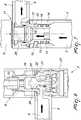
Figure 1 is a perspective view of the device according to the invention, in an active condition;Figure 2 is a perspective view of the device according to the invention, in another active condition;Figure 3 is a lateral view of the device according to the invention, in the active condition shown inFigure 1 ;Figure 4 is a rear view of the device according to the invention, in the active condition shown inFigure 1 ;Figure 5 is a cross-section ofFigure 4 along the axis V-V;Figure 6 is an enlarged detail ofFigure 5 ;Figure 7 is another enlarged detail ofFigure 5 ;Figure 8 is a plan view from above of the device according to the invention, in the active condition shown inFigure 1 ;Figure 9 is a plan view from below of the device according to the invention, in the active condition shown inFigure 1 .- With reference to the figures, the device according to the invention, generally designated by the
reference numeral 1, comprises adevice body 2 that can be associated, by one of its ends, with a hygienic-sanitary fixture such as a sink or the like and in which at least one duct for the passage ofwater 3 is defined. - Preferably, the
device body 2 has an elongated shape and is intended to be associated with the hygienic-sanitary fixture, not shown for the sake of simplicity, with its axis 4 substantially vertical. - The device in question further comprises a dispensing
spigot 5 that is connected, by one of its ends, to thedevice body 2. - Preferably, the dispensing
spigot 5 is connected to the upper end, which is opposite to the end to be connected to the hygienic-sanitary fixture, of thedevice body 2 and, on the inside, a correspondingwater passage duct 6 is defined which leads out through a dispensingoutlet 7 that is arranged in proximity to the end of the dispensingspigot 5 that is opposite to the end connected to thedevice body 2. Thiswater passage duct 6, which is defined inside the dispensingspigot 5, is connected to thewater passage duct 3 defined inside thedevice body 2. - The device in question also comprises an
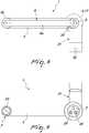
arm 8 which is associated, by one of its ends, with the dispensingspigot 5 and which terminates, at the opposite end, in a dispensingspray head 9. A correspondingwater passage duct 10 is also defined in thearm 8 which can be connected to thewater passage duct 3 that is defined in thedevice body 2. - According to the invention, the
arm 8 is articulated to a region of the dispensingspigot 5 which is spaced apart from the end of said dispensingspigot 5 that is connected to thedevice body 2. - Conveniently, the device in question is provided with means for
removable retention 11 of the end of thearm 8 that is provided with the dispensingspray head 9, which are proximate to the end of the dispensingspigot 5 that is connected to thedevice body 2. - The dispensing
spigot 5 is connected, by a first end thereof, to thedevice body 2, and its dispensingoutlet 7 is arranged at its opposite end or second end. Thearm 8 is articulated to the dispensingspigot 5 at this second end of the dispensingspigot 5. - More specifically, the dispensing
spigot 5 is screwed to acollar 12 that is inserted in the upper end of thedevice body 2. Thecollar 12, which acts as a connection between thewater passage duct 3 of thedevice body 2 and thewater passage duct 6 of the dispensingspigot 5, is provided, on its lateral surface, with a pair ofannular seats 13 inside whichcorresponding gaskets 14 are arranged, for example of the O-ring type, which ensure the outward seal of the water that flows through thedevice body 2 and through the dispensingspigot 5. Thecollar 12 is retained inside thedevice body 2 by means of a threadedgrub screw 15 that engages ananti-friction ring 33 that is inserted in anannular groove 16 defined in the lateral surface ofsaid collar 12. In this manner, although thecollar 12 is axially locked inside thedevice body 2, it can rotate in relation to saiddevice body 2 about an axis 17 that, preferably, coincides with the axis 4 of thedevice body 2. Due to this, the dispensingspigot 5, which extends preferably at right angles to the axis of thecollar 12 and thus at right angles to the axis 4 of thedevice body 2, is pivoted to thedevice body 2 and can be rotated in relation to thedevice body 2 about the axis 17 of thecollar 12 which constitutes its pivoting axis. - The
arm 8 is pivoted to the dispensingspigot 5 about apivoting axis 18 that is substantially parallel to the pivoting axis 17 of the dispensingspigot 5 to thedevice body 2.Such arm 8 can move from an inactive position, in which it extends in an arc-like shape from the second end of the dispensingspigot 5 to the first end of the dispensingspigot 5 and is retained with the dispensingspray head 9 in proximity to the first end of the dispensingspigot 5 by the aforementioned removable retention means 11, to multiple positions for use, in which it is disengaged with its end provided with the dispensingspray head 9 from the first end of the dispensingspigot 5. - More specifically, the end of the
arm 8 which is opposite to the end that is provided with the dispensingspray head 9, is screwed around an axially-perforated connectingelement 19 that is inserted, with a portion thereof, in the dispensingspigot 5. The connectingelement 19 passes through ahole 20, which is defined in the second end of the dispensingspigot 5 and aligned with the dispensingoutlet 7. The connectingelement 19, which can be inserted into the dispensingspigot 5 through the dispensingoutlet 7, has, on the portion thereof that is designed to remain inside the dispensingspigot 5, aflanging 21 that has a diameter larger than thehole 20 so that the extraction of the connectingelement 19 through saidhole 20 from the end opposite to the dispensingoutlet 7 is prevented. Conveniently arranged between theflanging 21 and the edge of thishole 20 is agasket 22 that prevents leaks of water between thearm 8 and the dispensingspigot 5. Thisgasket 22 is clamped by screwing thearm 8 around the connectingelement 19, which constitutes the assembly of thearm 8 onto the dispensingspigot 5. - The connecting
element 19 also acts as a connection between thewater passage duct 6 of the dispensingspigot 5 and thewater passage duct 10 of thearm 8. - Preferably, on the dispensing outlet 7 a
conventional aerator 23 is arranged which is not described in detail for simplicity. - Conveniently, the
water passage duct 10 of thearm 8 is connected to thewater passage duct 6 of the dispensingspigot 5 through avalve element 24 that is adapted to selectively connect thewater passage duct 6 of the dispensingspigot 5 to the dispensingoutlet 7 or to thewater passage duct 10 of thearm 8. - More specifically, the
valve element 24 is constituted by a conventional valve element that operates as a result of a difference in pressure upstream and downstream of the duct portion along which it is arranged.Such valve element 24 is arranged between the dispensingoutlet 7 and the connectingelement 19 and its position is switched following the opening/closing of the dispensingspray head 9, as illustrated in particular inFigure 6 . - The dispensing
spray head 9, connected to the end of thearm 8 opposite to the end thereof that is connected to the dispensingspigot 5, can be constituted by a conventional spray head provided with abutton 25 that controls the opening/closing thereof. The dispensingspray head 9 is constructed in such a way that it is closed if thebutton 25 is not pressed. - Advantageously, the means of
removable retention 11 of the end of thearm 8 that is provided with the dispensingspray head 9, at the first end of the dispensingspigot 5, are of the magnetic type. - More specifically, there is a
permanent magnet 26 inside the dispensingspigot 5, at its first end, and the end of the dispensingspray head 9 which can face the dispensingspigot 5 is made of ferromagnetic material, or there is a ring of ferromagnetic material around this end of the dispensingspray head 9. - The
permanent magnet 26, as illustrated, can be provided as a block arranged within a basket 27 that is accommodated inside thecollar 12. Between the basket 27 and thecollar 12 there are passages 28 for the water so as to ensure the connection between thewater passage duct 3 of thedevice body 2 and thewater passage duct 6 of the dispensingspigot 5, despite the presence of thepermanent magnet 26, as illustrated in particular inFigure 7 . - Advantageously, at least one
portion 8a of thearm 8, preferably an intermediate portion of the extension thereof, is flexible. - Conveniently, in the
device body 2 there is at least oneintake flow control element 31 is interposed between thisintake water passage duct 3 of thedevice body 2. - Preferably, in the
device body 2 twointakes intakes water passage duct 3 of thedevice body 2 there is aflow control element 31, which can be actuated by way of a knob orlever 32 and comprises a mixing cartridge, which is conventional and not shown in detail for the sake of simplicity. - The operation of the device according to the invention is as follows.
- Upon opening of the
flow control element 31, without pressing thebutton 25 arranged on the dispensingspray head 9, the water flows through thewater passage duct 3 of thedevice body 2 and through thewater passage duct 6 of the dispensingspigot 5 and exits through the dispensingoutlet 7, as shown inFigures 1 and6 . - When the user wants to use the dispensing
spray head 9 instead of the dispensingoutlet 7, he or she grips the dispensingspray head 9 and, overcoming the magnetic attraction exerted by thepermanent magnet 26 on the dispensingspray head 9, proceeds to orient it according to requirements, using the rotation of thearm 8 about the pivotingaxis 18 relative to thedispensing spigot 5 and optionally using the rotation of the dispensingspigot 5 relative to thedevice body 2 about the pivoting axis 17, as well as the flexibility of thearm 8 itself. - Once the desired position for the dispensing
spray head 9 has been reached, the user actuates the delivery of water through this dispensingspray head 9 by pressing thebutton 25. Opening the dispensingspray head 9 automatically results in the switching of the position of thevalve element 24 which cuts the connection between thewater passage duct 6 of the dispensingspigot 5 and the dispensingoutlet 7 and opens the connection between saidwater passage duct 6 of the dispensingspigot 5 and the water passage duct of thearm 8. - In this manner, the water is delivered through the dispensing
spray head 9, as illustrated inFigure 2 . - When the user releases the
button 25 of the dispensingspray head 9, the latter is closed and the position of thevalve element 24 is switched again, and once again results in the delivery of water through the dispensingoutlet 7. - In practice it has been found that the device according to the invention fully achieves the set aim since, thanks to the fact that the arm with the spray head is articulated to the dispensing spigot in a region thereof which is spaced apart from the device body, it makes it possible to move the spray head away from the device body to a larger extent than is permitted by conventional devices while offering, furthermore, the possibility of executing this operation without deforming the arm itself and thus maintain a direction of the water jet that is parallel to itself.
- The device, thus conceived, is susceptible of numerous modifications and variations, all of which are within the scope of the appended claims; thus, for example, the flow control element may not be integrated in the device but instead be associated with another part of the body of the sanitary fixture and can be of a type different from that described. In this case, the water passage duct that is defined in the device body is connected by way of a tube to the outflow duct of the flow control element which is in a position remote from the device according to the invention.
- In practice the materials employed, and the dimensions, may be any according to requirements and to the state of the art.
- Where technical features mentioned in any claim are followed by reference signs, those reference signs have been included for the sole purpose of increasing the intelligibility of the claims and accordingly, such reference signs do not have any limiting effect on the interpretation of each element identified by way of example by such reference signs.
Claims (10)
- A water dispensing device with spray head, particularly for sinks or similar hygienic-sanitary fixtures, which comprises:- a device body (2) that can be associated, by one of its ends, with a hygienic-sanitary fixture such as a sink or the like and in which at least one duct for the passage of water (3) is defined;- a dispensing spigot (5), which is connected, by one of its ends, to said device body (2); in said dispensing spigot (5) a corresponding duct for the passage of water (6) being defined which leads out through a dispensing outlet (7) and is connected to said water passage duct (3) that is defined in said device body (2);- an arm (8), which is associated, by one of its ends, with said dispensing spigot (5) and terminates in a dispensing spray head (9); in said arm (8) a corresponding water passage duct (10) being defined which can be connected to said water passage duct (3) that is defined in said device body (2);said arm (8) being articulated to a region of said dispensing spigot (5) which is spaced from the end of said dispensing spigot (5) which is connected to said device body (2);
said dispensing spigot (5) being connected, with a first end thereof, to said device body (2) and said dispensing outlet (7) being located at its opposite end or second end; said device body (2) extending around a corresponding axis (4), said dispensing spigot (5) extending substantially at right angles to said axis (4) of the device body (2) and said arm (8) being pivoted to said dispensing spigot (5) about a pivoting axis (18) that is substantially parallel to said axis (4) of the device body (2);characterized in that said arm (8) is articulated to said dispensing spigot (5) at said second end of the dispensing spigot (5) andin that said dispensing spigot (5) is pivoted, with said first end, to said device body (2) about a corresponding pivoting axis (17) that is parallel to the pivoting axis (18) of said arm (8) to said dispensing spigot (5). - The device according to claim 1,characterized in that it comprises means (11) for the removable retention of the end of said arm (8), which is provided with said dispensing spray head (9), in proximity to the end of said dispensing spigot (5) that is connected to said device body (2).
- The device according to one or more of the preceding claims,characterized in that said water passage duct (10) of said arm (8) is connected to said water passage duct (6) of said dispensing spigot (5) through a valve element (24) that is adapted to selectively connect said water passage duct (6) of the dispensing spigot (5) to said dispensing outlet (7) or to said water passage duct (10) of the arm (8).
- The device according to claim 2,characterized in that said arm (8) can move from an inactive position, in which it extends in an arc-like shape from said second end of the dispensing spigot (5) to said first end of the dispensing spigot (5) and is retained with said dispensing spray head (9) in proximity to said first end of the dispensing spigot (5) by said removable retention means (11), to multiple positions for use, in which it is disengaged with its end that is provided with said dispensing spray head (9) from said first end of the dispensing spigot (5).
- The device according to claim 4,characterized in that said removable retention means (11) are of the magnetic type.
- The device according to one or more of the preceding claims,characterized in that said arm (8) has at least one flexible portion.
- The device according to claim 3,characterized in that the position of said valve element (24) can be switched by the opening or closing of said dispensing spray head (9).
- The device according to one or more of the preceding claims,characterized in that an aerator (23) is arranged on said dispensing outlet (7).
- The device according to one or more of the preceding claims,characterized in that in said device body (2) there is at least one intake (29, 30) that can be connected to a water supply duct, a flow control element (31) being interposed between said at least one intake (29, 30) and said water passage duct (3) of the device body (2).
- The device according to claim 1,characterized in that in said device body (2) there are two intakes (29, 30) that can be connected respectively to a cold water supply duct and to a hot water supply duct, a controllable flow control element (31) being interposed between said intakes (29, 30) and said water passage duct (3) of the device body (2) and comprising a mixing cartridge.
Applications Claiming Priority (1)
| Application Number | Priority Date | Filing Date | Title |
|---|---|---|---|
| ITMI20140072 | 2014-01-21 |
Publications (2)
| Publication Number | Publication Date |
|---|---|
| EP2896759A1 EP2896759A1 (en) | 2015-07-22 |
| EP2896759B1true EP2896759B1 (en) | 2019-01-09 |
Family
ID=50336438
Family Applications (1)
| Application Number | Title | Priority Date | Filing Date |
|---|---|---|---|
| EP15151826.3AActiveEP2896759B1 (en) | 2014-01-21 | 2015-01-20 | Water dispensing device with spray head, particularly for sinks or similar hygienic-sanitary fixtures, with improved manoeuverability |
Country Status (3)
| Country | Link |
|---|---|
| EP (1) | EP2896759B1 (en) |
| ES (1) | ES2719118T3 (en) |
| TR (1) | TR201904954T4 (en) |
Cited By (4)
| Publication number | Priority date | Publication date | Assignee | Title |
|---|---|---|---|---|
| US11125365B2 (en) | 2018-02-28 | 2021-09-21 | Kohler Co. | Magnetic joint |
| US11408543B2 (en) | 2018-02-28 | 2022-08-09 | Kohler Co. | Articulating faucet |
| US12054925B2 (en) | 2018-06-04 | 2024-08-06 | Kohler Co. | Articulating faucet |
| US12220715B2 (en) | 2019-12-13 | 2025-02-11 | Kohler Co. | Dual-head shower assemblies |
Families Citing this family (13)
| Publication number | Priority date | Publication date | Assignee | Title |
|---|---|---|---|---|
| CN107642629A (en)* | 2017-10-30 | 2018-01-30 | 路达(厦门)工业有限公司 | Faucet device |
| CN110067876B (en)* | 2018-01-24 | 2024-10-15 | 厦门松霖科技股份有限公司 | Tap head |
| US10890277B2 (en) | 2018-02-28 | 2021-01-12 | Kohler Co. | Articulating faucet with progressive magnetic joint |
| CN110552401B (en) | 2018-06-04 | 2021-09-03 | 科勒公司 | Hinged water tap |
| USD914143S1 (en) | 2019-08-08 | 2021-03-23 | Kraus Usa Plumbing Llc | Faucet |
| USD914144S1 (en) | 2019-08-13 | 2021-03-23 | Kraus Usa Plumbing Llc | Faucet |
| USD913438S1 (en) | 2019-08-13 | 2021-03-16 | ICG Licensing LLC | Faucet |
| USD913439S1 (en) | 2019-08-13 | 2021-03-16 | ICG Licensing LLC | Faucet |
| USD914146S1 (en) | 2019-08-14 | 2021-03-23 | Kraus Usa Plumbing Llc | Faucet |
| USD912780S1 (en) | 2019-08-14 | 2021-03-09 | ICG Licensing LLC | Faucet |
| USD914145S1 (en) | 2019-08-14 | 2021-03-23 | Kraus Usa Plumbing Llc | Faucet |
| USD996571S1 (en) | 2020-09-24 | 2023-08-22 | Kraus Usa Plumbing Llc | Faucet |
| DE102024106320A1 (en)* | 2024-03-05 | 2025-09-11 | Grohe Ag | Sanitary fitting with a hose |
Family Cites Families (5)
| Publication number | Priority date | Publication date | Assignee | Title |
|---|---|---|---|---|
| US1530050A (en)* | 1925-03-17 | Combination faucet | ||
| KR100517231B1 (en)* | 2005-02-12 | 2005-09-28 | 정현진 | Water faucet having crown gears for angle adjustment |
| US20070023094A1 (en)* | 2005-07-29 | 2007-02-01 | Young Wu C | Faucet |
| US8061386B2 (en)* | 2007-05-07 | 2011-11-22 | Kohler Co. | Swivel joint for faucet |
| US8869821B2 (en)* | 2011-07-19 | 2014-10-28 | Vito Laera | Extendable faucet spout |
- 2015
- 2015-01-20EPEP15151826.3Apatent/EP2896759B1/enactiveActive
- 2015-01-20TRTR2019/04954Tpatent/TR201904954T4/enunknown
- 2015-01-20ESES15151826Tpatent/ES2719118T3/enactiveActive
Non-Patent Citations (1)
| Title |
|---|
| None* |
Cited By (8)
| Publication number | Priority date | Publication date | Assignee | Title |
|---|---|---|---|---|
| US11125365B2 (en) | 2018-02-28 | 2021-09-21 | Kohler Co. | Magnetic joint |
| US11408543B2 (en) | 2018-02-28 | 2022-08-09 | Kohler Co. | Articulating faucet |
| US11639762B2 (en) | 2018-02-28 | 2023-05-02 | Kohler Co. | Articulating faucet |
| US11913574B2 (en) | 2018-02-28 | 2024-02-27 | Kohler Co. | Magnetic joint |
| US12085202B2 (en) | 2018-02-28 | 2024-09-10 | Kohler Co. | Articulating faucet |
| US12320452B2 (en) | 2018-02-28 | 2025-06-03 | Kohler Co. | Magnetic joint |
| US12054925B2 (en) | 2018-06-04 | 2024-08-06 | Kohler Co. | Articulating faucet |
| US12220715B2 (en) | 2019-12-13 | 2025-02-11 | Kohler Co. | Dual-head shower assemblies |
Also Published As
| Publication number | Publication date |
|---|---|
| ES2719118T3 (en) | 2019-07-08 |
| TR201904954T4 (en) | 2019-05-21 |
| EP2896759A1 (en) | 2015-07-22 |
Similar Documents
| Publication | Publication Date | Title |
|---|---|---|
| EP2896759B1 (en) | Water dispensing device with spray head, particularly for sinks or similar hygienic-sanitary fixtures, with improved manoeuverability | |
| US8985147B2 (en) | Fine ceramic control valve | |
| US10274096B2 (en) | Touch faucet | |
| US12138217B2 (en) | Combination emergency wash and faucet unit | |
| JP6970663B2 (en) | Integrated faucet filtration system | |
| CA2859105C (en) | Integrated kitchen faucet side spray and diverter | |
| US7458112B1 (en) | Shower assembly kit with multiple functions | |
| JP7410591B2 (en) | Mixing faucet for dispensing water | |
| US8122528B2 (en) | Shower device | |
| AU2018297218B2 (en) | Integrated mixed tap water and conditioned water faucet assembly with pull out sprayer head | |
| US20080245897A1 (en) | Showerhead | |
| US20100320295A1 (en) | Shower head apparatus with adjustable flow rate arrangement | |
| US20150096116A1 (en) | Water control system having a temperature controlled tub faucet valve | |
| US20140325752A1 (en) | Plumbing Fixtures for Shower and Bathtub | |
| EP3118496B1 (en) | Distributing, opening and closing device for taps | |
| CN107023689A (en) | Devices for opening and closing faucets and regulating the flow rate of faucets in bathrooms or kitchens | |
| US20160208946A1 (en) | Electronic plumbing fixture fitting with electronic valve having low closing force | |
| US20060207667A1 (en) | Fluid distribution device | |
| US9091358B2 (en) | Flow diverter device | |
| US20160090720A1 (en) | Two-Path Water Output Device | |
| JP2016050408A (en) | Stopcock and faucet device | |
| CN207878572U (en) | It is a kind of that there is the shower bath for being switched fast switch | |
| US20180106021A1 (en) | Sink System with Faucet in Sink Cover | |
| TWM502767U (en) | Shower faucet |
Legal Events
| Date | Code | Title | Description |
|---|---|---|---|
| PUAI | Public reference made under article 153(3) epc to a published international application that has entered the european phase | Free format text:ORIGINAL CODE: 0009012 | |
| 17P | Request for examination filed | Effective date:20150120 | |
| AK | Designated contracting states | Kind code of ref document:A1 Designated state(s):AL AT BE BG CH CY CZ DE DK EE ES FI FR GB GR HR HU IE IS IT LI LT LU LV MC MK MT NL NO PL PT RO RS SE SI SK SM TR | |
| AX | Request for extension of the european patent | Extension state:BA ME | |
| 17P | Request for examination filed | Effective date:20151118 | |
| RBV | Designated contracting states (corrected) | Designated state(s):AL AT BE BG CH CY CZ DE DK EE ES FI FR GB GR HR HU IE IS IT LI LT LU LV MC MK MT NL NO PL PT RO RS SE SI SK SM TR | |
| GRAP | Despatch of communication of intention to grant a patent | Free format text:ORIGINAL CODE: EPIDOSNIGR1 | |
| STAA | Information on the status of an ep patent application or granted ep patent | Free format text:STATUS: GRANT OF PATENT IS INTENDED | |
| INTG | Intention to grant announced | Effective date:20180725 | |
| GRAS | Grant fee paid | Free format text:ORIGINAL CODE: EPIDOSNIGR3 | |
| GRAA | (expected) grant | Free format text:ORIGINAL CODE: 0009210 | |
| STAA | Information on the status of an ep patent application or granted ep patent | Free format text:STATUS: THE PATENT HAS BEEN GRANTED | |
| AK | Designated contracting states | Kind code of ref document:B1 Designated state(s):AL AT BE BG CH CY CZ DE DK EE ES FI FR GB GR HR HU IE IS IT LI LT LU LV MC MK MT NL NO PL PT RO RS SE SI SK SM TR | |
| REG | Reference to a national code | Ref country code:GB Ref legal event code:FG4D | |
| REG | Reference to a national code | Ref country code:CH Ref legal event code:EP Ref country code:AT Ref legal event code:REF Ref document number:1087457 Country of ref document:AT Kind code of ref document:T Effective date:20190115 | |
| REG | Reference to a national code | Ref country code:IE Ref legal event code:FG4D | |
| REG | Reference to a national code | Ref country code:DE Ref legal event code:R096 Ref document number:602015023032 Country of ref document:DE | |
| REG | Reference to a national code | Ref country code:NL Ref legal event code:MP Effective date:20190109 | |
| REG | Reference to a national code | Ref country code:LT Ref legal event code:MG4D | |
| PG25 | Lapsed in a contracting state [announced via postgrant information from national office to epo] | Ref country code:NL Free format text:LAPSE BECAUSE OF FAILURE TO SUBMIT A TRANSLATION OF THE DESCRIPTION OR TO PAY THE FEE WITHIN THE PRESCRIBED TIME-LIMIT Effective date:20190109 | |
| REG | Reference to a national code | Ref country code:ES Ref legal event code:FG2A Ref document number:2719118 Country of ref document:ES Kind code of ref document:T3 Effective date:20190708 | |
| REG | Reference to a national code | Ref country code:AT Ref legal event code:MK05 Ref document number:1087457 Country of ref document:AT Kind code of ref document:T Effective date:20190109 | |
| PG25 | Lapsed in a contracting state [announced via postgrant information from national office to epo] | Ref country code:PL Free format text:LAPSE BECAUSE OF FAILURE TO SUBMIT A TRANSLATION OF THE DESCRIPTION OR TO PAY THE FEE WITHIN THE PRESCRIBED TIME-LIMIT Effective date:20190109 Ref country code:LT Free format text:LAPSE BECAUSE OF FAILURE TO SUBMIT A TRANSLATION OF THE DESCRIPTION OR TO PAY THE FEE WITHIN THE PRESCRIBED TIME-LIMIT Effective date:20190109 Ref country code:FI Free format text:LAPSE BECAUSE OF FAILURE TO SUBMIT A TRANSLATION OF THE DESCRIPTION OR TO PAY THE FEE WITHIN THE PRESCRIBED TIME-LIMIT Effective date:20190109 Ref country code:NO Free format text:LAPSE BECAUSE OF FAILURE TO SUBMIT A TRANSLATION OF THE DESCRIPTION OR TO PAY THE FEE WITHIN THE PRESCRIBED TIME-LIMIT Effective date:20190409 Ref country code:SE Free format text:LAPSE BECAUSE OF FAILURE TO SUBMIT A TRANSLATION OF THE DESCRIPTION OR TO PAY THE FEE WITHIN THE PRESCRIBED TIME-LIMIT Effective date:20190109 Ref country code:PT Free format text:LAPSE BECAUSE OF FAILURE TO SUBMIT A TRANSLATION OF THE DESCRIPTION OR TO PAY THE FEE WITHIN THE PRESCRIBED TIME-LIMIT Effective date:20190509 | |
| PG25 | Lapsed in a contracting state [announced via postgrant information from national office to epo] | Ref country code:HR Free format text:LAPSE BECAUSE OF FAILURE TO SUBMIT A TRANSLATION OF THE DESCRIPTION OR TO PAY THE FEE WITHIN THE PRESCRIBED TIME-LIMIT Effective date:20190109 Ref country code:RS Free format text:LAPSE BECAUSE OF FAILURE TO SUBMIT A TRANSLATION OF THE DESCRIPTION OR TO PAY THE FEE WITHIN THE PRESCRIBED TIME-LIMIT Effective date:20190109 Ref country code:BG Free format text:LAPSE BECAUSE OF FAILURE TO SUBMIT A TRANSLATION OF THE DESCRIPTION OR TO PAY THE FEE WITHIN THE PRESCRIBED TIME-LIMIT Effective date:20190409 Ref country code:IS Free format text:LAPSE BECAUSE OF FAILURE TO SUBMIT A TRANSLATION OF THE DESCRIPTION OR TO PAY THE FEE WITHIN THE PRESCRIBED TIME-LIMIT Effective date:20190509 Ref country code:LV Free format text:LAPSE BECAUSE OF FAILURE TO SUBMIT A TRANSLATION OF THE DESCRIPTION OR TO PAY THE FEE WITHIN THE PRESCRIBED TIME-LIMIT Effective date:20190109 Ref country code:GR Free format text:LAPSE BECAUSE OF FAILURE TO SUBMIT A TRANSLATION OF THE DESCRIPTION OR TO PAY THE FEE WITHIN THE PRESCRIBED TIME-LIMIT Effective date:20190410 | |
| REG | Reference to a national code | Ref country code:CH Ref legal event code:PL | |
| PG25 | Lapsed in a contracting state [announced via postgrant information from national office to epo] | Ref country code:LU Free format text:LAPSE BECAUSE OF NON-PAYMENT OF DUE FEES Effective date:20190120 | |
| REG | Reference to a national code | Ref country code:DE Ref legal event code:R097 Ref document number:602015023032 Country of ref document:DE | |
| REG | Reference to a national code | Ref country code:BE Ref legal event code:MM Effective date:20190131 | |
| REG | Reference to a national code | Ref country code:IE Ref legal event code:MM4A | |
| PG25 | Lapsed in a contracting state [announced via postgrant information from national office to epo] | Ref country code:EE Free format text:LAPSE BECAUSE OF FAILURE TO SUBMIT A TRANSLATION OF THE DESCRIPTION OR TO PAY THE FEE WITHIN THE PRESCRIBED TIME-LIMIT Effective date:20190109 Ref country code:RO Free format text:LAPSE BECAUSE OF FAILURE TO SUBMIT A TRANSLATION OF THE DESCRIPTION OR TO PAY THE FEE WITHIN THE PRESCRIBED TIME-LIMIT Effective date:20190109 Ref country code:SK Free format text:LAPSE BECAUSE OF FAILURE TO SUBMIT A TRANSLATION OF THE DESCRIPTION OR TO PAY THE FEE WITHIN THE PRESCRIBED TIME-LIMIT Effective date:20190109 Ref country code:CZ Free format text:LAPSE BECAUSE OF FAILURE TO SUBMIT A TRANSLATION OF THE DESCRIPTION OR TO PAY THE FEE WITHIN THE PRESCRIBED TIME-LIMIT Effective date:20190109 Ref country code:AL Free format text:LAPSE BECAUSE OF FAILURE TO SUBMIT A TRANSLATION OF THE DESCRIPTION OR TO PAY THE FEE WITHIN THE PRESCRIBED TIME-LIMIT Effective date:20190109 Ref country code:MC Free format text:LAPSE BECAUSE OF FAILURE TO SUBMIT A TRANSLATION OF THE DESCRIPTION OR TO PAY THE FEE WITHIN THE PRESCRIBED TIME-LIMIT Effective date:20190109 Ref country code:AT Free format text:LAPSE BECAUSE OF FAILURE TO SUBMIT A TRANSLATION OF THE DESCRIPTION OR TO PAY THE FEE WITHIN THE PRESCRIBED TIME-LIMIT Effective date:20190109 Ref country code:DK Free format text:LAPSE BECAUSE OF FAILURE TO SUBMIT A TRANSLATION OF THE DESCRIPTION OR TO PAY THE FEE WITHIN THE PRESCRIBED TIME-LIMIT Effective date:20190109 | |
| PLBE | No opposition filed within time limit | Free format text:ORIGINAL CODE: 0009261 | |
| STAA | Information on the status of an ep patent application or granted ep patent | Free format text:STATUS: NO OPPOSITION FILED WITHIN TIME LIMIT | |
| PG25 | Lapsed in a contracting state [announced via postgrant information from national office to epo] | Ref country code:SM Free format text:LAPSE BECAUSE OF FAILURE TO SUBMIT A TRANSLATION OF THE DESCRIPTION OR TO PAY THE FEE WITHIN THE PRESCRIBED TIME-LIMIT Effective date:20190109 Ref country code:BE Free format text:LAPSE BECAUSE OF NON-PAYMENT OF DUE FEES Effective date:20190131 | |
| 26N | No opposition filed | Effective date:20191010 | |
| GBPC | Gb: european patent ceased through non-payment of renewal fee | Effective date:20190409 | |
| PG25 | Lapsed in a contracting state [announced via postgrant information from national office to epo] | Ref country code:CH Free format text:LAPSE BECAUSE OF NON-PAYMENT OF DUE FEES Effective date:20190131 Ref country code:LI Free format text:LAPSE BECAUSE OF NON-PAYMENT OF DUE FEES Effective date:20190131 | |
| PG25 | Lapsed in a contracting state [announced via postgrant information from national office to epo] | Ref country code:GB Free format text:LAPSE BECAUSE OF NON-PAYMENT OF DUE FEES Effective date:20190409 Ref country code:IE Free format text:LAPSE BECAUSE OF NON-PAYMENT OF DUE FEES Effective date:20190120 | |
| PG25 | Lapsed in a contracting state [announced via postgrant information from national office to epo] | Ref country code:SI Free format text:LAPSE BECAUSE OF FAILURE TO SUBMIT A TRANSLATION OF THE DESCRIPTION OR TO PAY THE FEE WITHIN THE PRESCRIBED TIME-LIMIT Effective date:20190109 | |
| PG25 | Lapsed in a contracting state [announced via postgrant information from national office to epo] | Ref country code:MT Free format text:LAPSE BECAUSE OF NON-PAYMENT OF DUE FEES Effective date:20190120 | |
| PG25 | Lapsed in a contracting state [announced via postgrant information from national office to epo] | Ref country code:CY Free format text:LAPSE BECAUSE OF FAILURE TO SUBMIT A TRANSLATION OF THE DESCRIPTION OR TO PAY THE FEE WITHIN THE PRESCRIBED TIME-LIMIT Effective date:20190109 | |
| PG25 | Lapsed in a contracting state [announced via postgrant information from national office to epo] | Ref country code:HU Free format text:LAPSE BECAUSE OF FAILURE TO SUBMIT A TRANSLATION OF THE DESCRIPTION OR TO PAY THE FEE WITHIN THE PRESCRIBED TIME-LIMIT; INVALID AB INITIO Effective date:20150120 | |
| PG25 | Lapsed in a contracting state [announced via postgrant information from national office to epo] | Ref country code:MK Free format text:LAPSE BECAUSE OF FAILURE TO SUBMIT A TRANSLATION OF THE DESCRIPTION OR TO PAY THE FEE WITHIN THE PRESCRIBED TIME-LIMIT Effective date:20190109 | |
| P01 | Opt-out of the competence of the unified patent court (upc) registered | Effective date:20230529 | |
| PGFP | Annual fee paid to national office [announced via postgrant information from national office to epo] | Ref country code:DE Payment date:20250120 Year of fee payment:11 | |
| PGFP | Annual fee paid to national office [announced via postgrant information from national office to epo] | Ref country code:ES Payment date:20250203 Year of fee payment:11 | |
| PGFP | Annual fee paid to national office [announced via postgrant information from national office to epo] | Ref country code:FR Payment date:20250121 Year of fee payment:11 | |
| PGFP | Annual fee paid to national office [announced via postgrant information from national office to epo] | Ref country code:IT Payment date:20250120 Year of fee payment:11 | |
| PGFP | Annual fee paid to national office [announced via postgrant information from national office to epo] | Ref country code:TR Payment date:20250110 Year of fee payment:11 |